WO2023131035A1 - Impact damage numerical simulation optimization method based on laser mapping of entity grid - Google Patents
Impact damage numerical simulation optimization method based on laser mapping of entity gridDownload PDFInfo
- Publication number
- WO2023131035A1 WO2023131035A1PCT/CN2022/143082CN2022143082WWO2023131035A1WO 2023131035 A1WO2023131035 A1WO 2023131035A1CN 2022143082 WCN2022143082 WCN 2022143082WWO 2023131035 A1WO2023131035 A1WO 2023131035A1
- Authority
- WO
- WIPO (PCT)
- Prior art keywords
- impact
- damage
- grid
- impact damage
- finite element
- Prior art date
- Legal status (The legal status is an assumption and is not a legal conclusion. Google has not performed a legal analysis and makes no representation as to the accuracy of the status listed.)
- Ceased
Links
Images


Classifications
- G—PHYSICS
- G06—COMPUTING OR CALCULATING; COUNTING
- G06F—ELECTRIC DIGITAL DATA PROCESSING
- G06F30/00—Computer-aided design [CAD]
- G06F30/20—Design optimisation, verification or simulation
- G06F30/23—Design optimisation, verification or simulation using finite element methods [FEM] or finite difference methods [FDM]
- G—PHYSICS
- G06—COMPUTING OR CALCULATING; COUNTING
- G06F—ELECTRIC DIGITAL DATA PROCESSING
- G06F30/00—Computer-aided design [CAD]
- G06F30/20—Design optimisation, verification or simulation
- G—PHYSICS
- G06—COMPUTING OR CALCULATING; COUNTING
- G06T—IMAGE DATA PROCESSING OR GENERATION, IN GENERAL
- G06T17/00—Three dimensional [3D] modelling, e.g. data description of 3D objects
- G06T17/20—Finite element generation, e.g. wire-frame surface description, tesselation
- G—PHYSICS
- G06—COMPUTING OR CALCULATING; COUNTING
- G06F—ELECTRIC DIGITAL DATA PROCESSING
- G06F2111/00—Details relating to CAD techniques
- G06F2111/10—Numerical modelling
- G—PHYSICS
- G06—COMPUTING OR CALCULATING; COUNTING
- G06F—ELECTRIC DIGITAL DATA PROCESSING
- G06F2119/00—Details relating to the type or aim of the analysis or the optimisation
- G06F2119/02—Reliability analysis or reliability optimisation; Failure analysis, e.g. worst case scenario performance, failure mode and effects analysis [FMEA]
- G—PHYSICS
- G06—COMPUTING OR CALCULATING; COUNTING
- G06F—ELECTRIC DIGITAL DATA PROCESSING
- G06F2119/00—Details relating to the type or aim of the analysis or the optimisation
- G06F2119/14—Force analysis or force optimisation, e.g. static or dynamic forces
Definitions
- the inventionbelongs to the technical field of impact damage reproduction, impact damage tolerance and maintainability evaluation of aeroengine blades, and in particular relates to a numerical simulation optimization method for impact damage based on laser mapping entity grids.
- the aero-engineDuring the take-off and landing of the aircraft, the aero-engine often inhales hard objects such as small stones, gravel and metal, and impacts the engine fan/compressor blades, causing impact damage such as pits, gaps, tears, scratches, etc. Fatigue strength decline of the blade shortens the fatigue life of the blade and makes it one of the main factors for premature fracture in the service cycle. Therefore, the impact damage tolerance and maintainability evaluation of the damaged blade must be carried out. Impact damage often has significant stress concentration and residual stress, which has a serious impact on the fatigue performance of the damaged blade.
- the surface residual stress distributioncan be obtained by measuring the residual stress measuring equipment, but it is almost impossible to directly measure the complete internal residual stress distribution.
- material impact damagesuch as ANSYS Ls-dyna or Abaqus.
- the dispersion of the actual impact processsuch as bullet attitude, bullseye position, etc.
- the nominal impact conditionsare used to do The error between the numerical simulation results and the experimental results is often large.
- the failure strain in the material modelnot only has a great influence on the numerical simulation results, but also is difficult to obtain accurately through experimental methods. Therefore, it is difficult to obtain accurate residual stress values through the existing numerical simulation methods of impact damage, and even the distribution form is far from the actual results. Therefore, the existing methods have met the requirements of impact damage fatigue performance prediction. Therefore, there is a need for a method to improve the numerical simulation accuracy of impact damage geometry and internal residual stress.
- the purpose of the present inventionis to propose a numerical simulation optimization method of impact damage based on laser mapping solid mesh according to the notch size, profile, residual stress and residual strain after impact damage as constraint variables to solve the problem of impact damage geometry and internal residual Stress numerical simulation accuracy problem.
- the present inventionprovides following technical scheme:
- a numerical simulation optimization method for impact damage based on laser mapping solid meshcomprising the following steps:
- the first stepis to use laser etching to enlarge the finite element grid scale and map it on the surface of the sample to be impacted to form a surface solid grid unit, and then use a light gas cannon to fire bullets to impact the sample grid area to obtain impact damage, and then measure Impact damage size, damage profile, surface residual strain and surface residual stress of solid mesh elements around the damage;
- the second stepis to establish a parametric impact finite element model through the finite element software, set the material model parameters of the bullet and the sample, and solve after defining the constraints to obtain the numerically simulated impact damage size, the numerically simulated impact damage profile, and the numerically simulated Surface residual strain and residual stress of surface solid mesh elements;
- the third stepis to calculate the relative error of the impact damage size, damage contour, surface residual strain and residual stress between the experimental measurement and the numerical simulation;
- the fourth stepis to judge whether the relative error in the third step is less than the expected value. If it exceeds the expected value, change the optimization variables including impact parameters, material model parameters and grid size parameters, and repeat the first to third steps until the satisfaction is obtained. Numerical simulation results for precision requirements.
- the shape and direction of the surface grid of the sample in the area to be impactedare the same as that of the solid surface grid of the sample in the finite element, both of which are quadrilateral grids, and the size is a multiple relationship; the solid grid It has line width, line interval and line direction, obtained by laser etching, and the etching depth does not exceed 0.1mm. After the etching is completed, the units of the solid grid and the intersection points of the engraved lines are numbered according to the coordinates.
- a light gas gunis used to launch a bullet with a specified shape and size at a set impact angle and impact velocity.
- the bullet shapeincludes spherical, square, and cylindrical shapes, and the impact sample entity grid area specifies a position Obtain impact damage, which includes pits and notches.
- the surface residual strain of the surface mesh unit around the impact damageis obtained by a non-contact digital image correlation measurement system by comparing the deformation of the surface mesh of the object before and after the impact; the surface mesh of the object around the impact damage
- the residual stress on the surface of the grid unitis obtained by calculating the arithmetic average of the residual stress values at each node position measured by the micro-area X-ray stress instrument; the geometric size of the impact damage is measured by a numerical optical microscope, and the size of the impact damage includes damage depth, damage length, and damage width.
- the parameterized impact finite element model of the establishmentincludes the finite element mesh model of the bullet and the sample, the attitude of the bullet, the position of the bullet relative to the sample, and the defined constraints include impact velocity and impact angle.
- the relative error of the damage profileis expressed as:
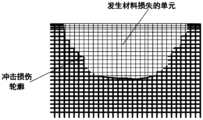
- n eis the number of finite element elements contained in the physical surface elements, is the number of deleted finite element elements within the scope of the i-th physical surface unit where material loss occurs; for the case where the solid mesh is completely lost and the corresponding finite element mesh is completely deleted, The ratio to ne is 1, and the smaller the SIM value is, the closer the residual grid profile after the numerical simulation of grid loss is to the actual impact damage profile.
- the relative errors of the residual strain and residual stress on the surface of the impact damaged grid in the case of the solid grid and the finite element gridare respectively expressed as:
- the units for surface residual strain and residual stress measurementonly include units in the band-shaped area with a radius ranging from 1 times the maximum damage depth to 2 times the maximum damage depth, and n is the number of surface units in the band-shaped area; are the residual strain and residual stress of the finite element grid unit for numerical simulation of impact damage, respectively, Respectively, the residual strain and residual stress of the test simulated impact damaged solid grid unit, ⁇ R ⁇ is the relative error of the residual strain of the impact damaged grid surface; ⁇ R ⁇ is the relative error of the residual stress of the impact damaged grid surface.
- the impact parameteris the bullet attitude parameter and the position parameter of the bullet relative to the sample
- the material model parameteris the failure strain parameter
- the grid size parameteris the ratio of the size of the grid unit on the surface of the object to the size of the finite element grid unit .
- the present inventionproposes a numerical simulation optimization method of impact damage based on laser mapping solid grid, which provides a reasonable and standardized optimization method and process for the numerical simulation calculation of impact damage of aeroengine blades.
- the core ideais to use laser mapping grid
- Associating the finite element numerical model with the real physical modelcan also avoid the problem of grid shedding caused by impact, and calibrate the numerical simulation results of the finite element method based on the measured results of the impact test.
- the present inventioncombines the impact test measurement means and the finite element analysis method, adjusts the calculation parameters and calibrates the numerical simulation results according to the relative error values of the residual contour, surface residual strain and residual stress, and can solve the accuracy problems of the impact damage geometry and internal residual stress numerical simulation. It is beneficial to further evaluate and determine the impact damage tolerance and its maintainability.
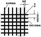
- Figure 1is a schematic diagram of the proportional relationship between the solid mesh and the finite element mesh
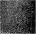
- Fig. 2is the physical picture of the solid mesh of the laser etching of the titanium alloy sample to be impacted
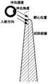
- Figure 3is a schematic diagram of the position of the impact bull's-eye
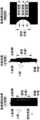
- Fig. 4is a comparison chart of the size of the impact damage obtained by the test and the size of the impact damage obtained by the digital simulation;
- Figure 5is a schematic diagram of the outline of the unit with material loss and impact damage
- Fig. 6is the regional schematic diagram of measuring surface residual strain and residual stress
- Fig. 7is a schematic diagram of bullet body posture and bullseye position adjustment.
- the present inventionis a method for numerical simulation and optimization of impact damage based on laser mapping entity grid, which includes the following steps:
- the first stepis to use laser etching to enlarge the finite element grid scale and map it on the surface of the sample to be impacted to form a surface solid grid unit, and then use a light gas gun to fire bullets to impact the sample grid area to obtain impact damage and then measure the impact Damage size (including damage depth, damage length, damage width), damage contour, surface residual strain and surface residual stress of solid grid cells around the damage.
- laser etchingto enlarge the finite element grid scale and map it on the surface of the sample to be impacted to form a surface solid grid unit
- a light gas gunto fire bullets to impact the sample grid area to obtain impact damage and then measure the impact Damage size (including damage depth, damage length, damage width), damage contour, surface residual strain and surface residual stress of solid grid cells around the damage.
- a laser marking machineis used to perform high-energy etching on the area of the sample to be impacted to obtain a solid grid.
- the etching depthdoes not exceed 0.1mm, and the units and nodes (intersection points of the engraved lines) of the solid grid are numbered according to the coordinates.
- the solid gridhas a certain line width, line interval and line direction, which is the proportional mapping of the finite element element grid, that is, the shape and direction of the grid on the surface of the sample are the same as the shape of the finite element grid on the surface of the solid model, and the size is a multiple Relationship, as shown in FIG. 1 , the size of the solid grid in this embodiment is twice the width of the laser scribe line.
- a laser marking machinewas used to perform high-energy etching on the impact area of the TC4 titanium alloy flat sample to obtain a solid grid, as shown in Figure 2.
- the second stepis to establish a parameterized impact finite element model (including the finite element mesh model of the bullet and the sample, the attitude of the bullet, and the position of the bullet relative to the sample) through the finite element software, and set the material model parameters of the bullet and the sample , define constraints (including impact velocity and impact angle) and then solve them to obtain the numerically simulated impact damage size, numerically simulated impact damage contour, and numerically simulated surface residual strain and residual stress of the surface solid mesh unit.
- a parameterized impact finite element modelincluding the finite element mesh model of the bullet and the sample, the attitude of the bullet, and the position of the bullet relative to the sample
- constraintsincluding impact velocity and impact angle
- the impact model of the sample and the bulletis modeled through the APDL module of the ANSYS software, including the geometric model of the sample, the geometric model of the bullet, the posture of the bullet (such as the position of the sides and corners of the square projectile relative to the coordinate system) and the The position where the ballistic trajectory calculated by the angle and impact velocity falls on the surface of the sample (bullseye position, as shown in Figure 3) is modeled.
- the sample modelis meshed according to the laser mapping solid mesh ratio mapping relationship in the "first step", and the mesh type is hexahedral element.
- the density of the solid gridis generally lower than that of the finite element grid.
- the size of the solid gridis 4 times the size of the finite element grid, as shown in Figure 1 .
- the finite element numerical solutionis carried out to obtain the impact Mesh residual profile, mesh surface residual strain, and surface residual stress data after loss of a damaged FE mesh.
- the third stepis to calculate the relative error of the impact damage size, damage contour, surface residual strain and residual stress between the experimental measurement and the numerical simulation; among them, the solid mesh (test) and the finite element mesh (numerical) are used to calculate the scale specifications.
- Figure 4The comparison of the size of the impact damage obtained from the test with the size of the impact damage obtained from the numerical simulation is shown in Figure 4, which includes the front view and side view of the numerical simulation results, and the front view of the test results; for the front view, there are incident side and the exit side (distinguished by the midline of the leading edge), measure the damage length l on the exit side; for the side view, the damage length l, damage depth d 1 , damage depth d 2 , damage depth d 3 .
- n eis the number of finite element elements contained in the physical surface elements, is the number of deleted finite element elements within the scope of the i-th physical surface unit where material loss occurs; for the case where the solid mesh is completely lost and the corresponding finite element mesh is completely deleted, The ratio to ne is 1, and the smaller the SIM value is, the closer the residual grid profile after the numerical simulation of grid loss is to the actual impact damage profile.
- the contours of the elements with material loss and impact damageare shown in Fig. 5.
- the units for surface residual strain and residual stress measurementonly include units in a band-shaped region with a radius ranging from 1 time of the maximum damage depth to a radius of 2 times the maximum damage depth, as shown in Figure 6, where n in the above formula is the band The number of surface units in the shape area.
- ⁇ R ⁇is the relative error of the residual strain of the impact damaged grid surface
- ⁇ R ⁇is the relative error of the residual stress of the impact damaged grid surface
- the fourth stepis to judge whether the relative error in the third step is less than the expected value. If it exceeds the expected value, change the optimization variables including impact parameters, material model parameters and grid size parameters. Repeat the above steps until the numerical simulation that meets the accuracy requirements is obtained. result.
- the relative error of the residual profile after the mesh loss of the impact damage in the third step, the residual strain of the mesh surface, and the residual stressis less than the expected value, which is 10% in this embodiment, and if it is not less than the expected value, then change
- the impact parameters of the numerical simulation in the "second step"including bullet body posture and bullseye position, as shown in Figure 7
- material model parametersincluding failure strain
- mesh size parametersincluding solid mesh size and finite element network grid size ratio
Landscapes
- Engineering & Computer Science (AREA)
- Physics & Mathematics (AREA)
- Theoretical Computer Science (AREA)
- Geometry (AREA)
- General Physics & Mathematics (AREA)
- Computer Hardware Design (AREA)
- Evolutionary Computation (AREA)
- General Engineering & Computer Science (AREA)
- Computer Graphics (AREA)
- Software Systems (AREA)
- Investigating Strength Of Materials By Application Of Mechanical Stress (AREA)
Abstract
Description
Translated fromChinese本申请要求于2022年1月5日提交中国专利局、申请号为202210006738.3、发明名称为“一种基于激光映射实体网格的冲击损伤数值模拟优化方法”的中国专利申请的优先权,其全部内容通过引用结合在本申请中。This application claims the priority of the Chinese patent application with the application number 202210006738.3 and the title of the invention "A Method for Numerical Simulation and Optimization of Impact Damage Based on Laser Mapping Solid Grid" submitted to the China Patent Office on January 5, 2022, all of which The contents are incorporated by reference in this application.
本发明属于航空发动机叶片冲击损伤再现、冲击损伤容限及维修性评估技术领域,尤其涉及一种基于激光映射实体网格的冲击损伤数值模拟优化方法。The invention belongs to the technical field of impact damage reproduction, impact damage tolerance and maintainability evaluation of aeroengine blades, and in particular relates to a numerical simulation optimization method for impact damage based on laser mapping entity grids.
飞机在起飞和降落过程中,航空发动机时常会吸入小石子、砂砾和金属等硬物,并冲击发动机风扇/压气机叶片,造成凹坑、缺口、撕裂、划痕等冲击损伤,它们是造成叶片疲劳强度衰退,缩短叶片疲劳寿命,使其在服役周期内过早断裂的主要因素之一,因此必须对损伤叶片进行冲击损伤容限和维修性评估。冲击损伤往往具有显著的应力集中和残余应力,对损伤叶片的疲劳性能具有严重的影响。During the take-off and landing of the aircraft, the aero-engine often inhales hard objects such as small stones, gravel and metal, and impacts the engine fan/compressor blades, causing impact damage such as pits, gaps, tears, scratches, etc. Fatigue strength decline of the blade shortens the fatigue life of the blade and makes it one of the main factors for premature fracture in the service cycle. Therefore, the impact damage tolerance and maintainability evaluation of the damaged blade must be carried out. Impact damage often has significant stress concentration and residual stress, which has a serious impact on the fatigue performance of the damaged blade.
目前,表面残余应力分布可通过残余应力测量设备测量获得,而目前直接测量完整的内部残余应力分布几乎不可能实现,通过腐蚀剥层法测试内部残余应力的时间成本的物质成本较高,无法满足工程需求。所以,借助于有限元软件的数值模拟方法成为有效获得材料冲击损伤内部残余应力分布的有效手段,例如ANSYS Ls-dyna或Abaqus等。但是,由于实际冲击过程具有分散性,例如子弹姿态、靶心位置等与名义试验参数具有差异,且这种差异对冲击损伤的几何形貌和残余应力具有显著的影响,所以采用名义冲击条件去做数值模拟的结果与实验结果的误差往往较大。同时,材料模型中失效应变不仅对数值模拟结果的影响较大,而且难以通过实验方法准确获得。因此,通过现有的冲击损伤数值模拟手段难以获得准确的残余应力数值,甚至分布形式与实际结果也相差甚远,所以现有手段已满足冲击损伤疲劳性能预测的要求。因此,需要一种提高冲击损伤几何和内部残余应力数值模拟精度的方法。At present, the surface residual stress distribution can be obtained by measuring the residual stress measuring equipment, but it is almost impossible to directly measure the complete internal residual stress distribution. Engineering needs. Therefore, the numerical simulation method with the help of finite element software has become an effective means to obtain the internal residual stress distribution of material impact damage, such as ANSYS Ls-dyna or Abaqus. However, due to the dispersion of the actual impact process, such as bullet attitude, bullseye position, etc., are different from the nominal test parameters, and this difference has a significant impact on the geometric shape and residual stress of the impact damage, so the nominal impact conditions are used to do The error between the numerical simulation results and the experimental results is often large. At the same time, the failure strain in the material model not only has a great influence on the numerical simulation results, but also is difficult to obtain accurately through experimental methods. Therefore, it is difficult to obtain accurate residual stress values through the existing numerical simulation methods of impact damage, and even the distribution form is far from the actual results. Therefore, the existing methods have met the requirements of impact damage fatigue performance prediction. Therefore, there is a need for a method to improve the numerical simulation accuracy of impact damage geometry and internal residual stress.
发明内容Contents of the invention
本发明的目的在于按照冲击损伤后的缺口尺寸、轮廓、残余应力和残余应 变作为约束变量,提出了一种基于激光映射实体网格的冲击损伤数值模拟优化方法,以解决冲击损伤几何和内部残余应力的数值模拟精度问题。The purpose of the present invention is to propose a numerical simulation optimization method of impact damage based on laser mapping solid mesh according to the notch size, profile, residual stress and residual strain after impact damage as constraint variables to solve the problem of impact damage geometry and internal residual Stress numerical simulation accuracy problem.
为达上述目的,本发明提供了如下技术方案:For reaching above-mentioned purpose, the present invention provides following technical scheme:
一种基于激光映射实体网格的冲击损伤数值模拟优化方法,包括如下步骤:A numerical simulation optimization method for impact damage based on laser mapping solid mesh, comprising the following steps:
第一步,使用激光刻蚀将有限元网格比例放大后映射于试样待冲击区表面形成表面实体网格单元,然后采用轻气炮发射子弹冲击试样网格区域获得冲击损伤后,测量冲击损伤尺寸、损伤轮廓、损伤周围实体网格单元的表面残余应变以及表面残余应力;The first step is to use laser etching to enlarge the finite element grid scale and map it on the surface of the sample to be impacted to form a surface solid grid unit, and then use a light gas cannon to fire bullets to impact the sample grid area to obtain impact damage, and then measure Impact damage size, damage profile, surface residual strain and surface residual stress of solid mesh elements around the damage;
第二步,通过有限元软件建立参数化的冲击有限元模型,设置子弹与试样的材料模型参数,定义约束后求解,得到数值模拟的冲击损伤尺寸、数值模拟的冲击损伤轮廓、数值模拟的表面实体网格单元的表面残余应变和残余应力;The second step is to establish a parametric impact finite element model through the finite element software, set the material model parameters of the bullet and the sample, and solve after defining the constraints to obtain the numerically simulated impact damage size, the numerically simulated impact damage profile, and the numerically simulated Surface residual strain and residual stress of surface solid mesh elements;
第三步,计算试验实测与数值模拟的冲击损伤尺寸、损伤轮廓、表面残余应变和残余应力的相对误差;The third step is to calculate the relative error of the impact damage size, damage contour, surface residual strain and residual stress between the experimental measurement and the numerical simulation;
第四步,判断第三步中相对误差是否均小于预期值,若超过预期值则改变优化变量包括冲击参数、材料模型参数及网格尺寸参数,重复第一步至第三步,直到获得满足精度要求的数值模拟结果。The fourth step is to judge whether the relative error in the third step is less than the expected value. If it exceeds the expected value, change the optimization variables including impact parameters, material model parameters and grid size parameters, and repeat the first to third steps until the satisfaction is obtained. Numerical simulation results for precision requirements.
可选地,所述第一步中,待冲击区域的试样实物表面网格形状、方向与有限元中试样实体表面网格相同,均为四边形网格,尺寸为倍数关系;实体网格具有线宽、线条间隔和线条方向,通过激光刻蚀获得,刻蚀深度不超过0.1mm,完成刻蚀后根据坐标对实体网格各单元和刻线交点进行编号。Optionally, in the first step, the shape and direction of the surface grid of the sample in the area to be impacted are the same as that of the solid surface grid of the sample in the finite element, both of which are quadrilateral grids, and the size is a multiple relationship; the solid grid It has line width, line interval and line direction, obtained by laser etching, and the etching depth does not exceed 0.1mm. After the etching is completed, the units of the solid grid and the intersection points of the engraved lines are numbered according to the coordinates.
可选地,所述第一步中,采用轻气炮以设定的冲击角度、冲击速度发射指定形状尺寸的子弹,子弹形状包括球形、方形、圆柱形,冲击试样实体网格区域指定位置获得冲击损伤,冲击损伤包括凹坑、缺口。Optionally, in the first step, a light gas gun is used to launch a bullet with a specified shape and size at a set impact angle and impact velocity. The bullet shape includes spherical, square, and cylindrical shapes, and the impact sample entity grid area specifies a position Obtain impact damage, which includes pits and notches.
可选地,所述第一步中,冲击损伤周围实物表面网格单元的表面残余应变由非接触式数字图像相关测量系统通过对比冲击前后实物表面网格的变形得到;冲击损伤周围实物表面网格单元表面残余应力由微区X射线应力仪测量各节点位置的残余应力值后求算数平均得到;通过数值光学显微镜测量冲击损伤几何尺寸,冲击损伤尺寸包括损伤深度、损伤长度、损伤宽度。Optionally, in the first step, the surface residual strain of the surface mesh unit around the impact damage is obtained by a non-contact digital image correlation measurement system by comparing the deformation of the surface mesh of the object before and after the impact; the surface mesh of the object around the impact damage The residual stress on the surface of the grid unit is obtained by calculating the arithmetic average of the residual stress values at each node position measured by the micro-area X-ray stress instrument; the geometric size of the impact damage is measured by a numerical optical microscope, and the size of the impact damage includes damage depth, damage length, and damage width.
可选地,所述第二步中,建立的参数化的冲击有限元模型包括子弹与试样 的有限元网格模型、子弹姿态、子弹相对于试样的位置,定义的约束包括冲击速度和冲击角度。Optionally, in the second step, the parameterized impact finite element model of the establishment includes the finite element mesh model of the bullet and the sample, the attitude of the bullet, the position of the bullet relative to the sample, and the defined constraints include impact velocity and impact angle.
可选地,所述第三步中,损伤轮廓的相对误差表示为:Optionally, in the third step, the relative error of the damage profile is expressed as:

其中,


可选地,所述第三步中,计算比例规格的实体网格与有限元网格两种情况下冲击损伤尺寸的相对误差表示:Optionally, in the third step, calculate the relative error representation of the impact damage size in the two cases of the solid mesh of the scale specification and the finite element mesh:

其中,


可选地,所述第三步中,实体网格与有限元网格两种情况下冲击损伤网格表面残余应变和残余应力的相对误差分别表示为:Optionally, in the third step, the relative errors of the residual strain and residual stress on the surface of the impact damaged grid in the case of the solid grid and the finite element grid are respectively expressed as:


其中,进行表面残余应变和残余应力测量的单元仅包括半径范围为1倍最大损伤深度至半径为2倍最大损伤深度带状区域内单元,n为带状区域表面单元的个数;

可选地,所述冲击参数为子弹姿态参量和子弹相对于试样的位置参量,材料模型参数为失效应变参数,网格尺寸参数为实物表面网格单元尺寸与有限元网格单元尺寸的比值。Optionally, the impact parameter is the bullet attitude parameter and the position parameter of the bullet relative to the sample, the material model parameter is the failure strain parameter, and the grid size parameter is the ratio of the size of the grid unit on the surface of the object to the size of the finite element grid unit .
本发明的有益效果是:The beneficial effects of the present invention are:
本发明提出了一种基于激光映射实体网格的冲击损伤数值模拟优化方法,为航空发动机叶片的冲击损伤数值模拟计算提供了一种合理规范的优化方法和流程,核心思想是通过激光映射网格将有限元数值模型与现实实体模型相关联,也可以避免冲击导致网格脱落问题,基于冲击试验的实测结果来校准有限元法的数值模拟结果。本发明结合冲击试验测量手段和有限元分析方法,根据残余轮廓、表面残余应变和残余应力的相对误差值调整计算参数校准数值模拟结果,可以解决冲击损伤几何和内部残余应力数值模拟的精度问题,有益于进一步评估和确定冲击损伤容限及其维修性。The present invention proposes a numerical simulation optimization method of impact damage based on laser mapping solid grid, which provides a reasonable and standardized optimization method and process for the numerical simulation calculation of impact damage of aeroengine blades. The core idea is to use laser mapping grid Associating the finite element numerical model with the real physical model can also avoid the problem of grid shedding caused by impact, and calibrate the numerical simulation results of the finite element method based on the measured results of the impact test. The present invention combines the impact test measurement means and the finite element analysis method, adjusts the calculation parameters and calibrates the numerical simulation results according to the relative error values of the residual contour, surface residual strain and residual stress, and can solve the accuracy problems of the impact damage geometry and internal residual stress numerical simulation. It is beneficial to further evaluate and determine the impact damage tolerance and its maintainability.
说明书附图Instructions attached
为了更清楚地说明本发明实施例或现有技术中的技术方案,下面将对实施例中所需要使用的附图作简单地介绍,显而易见地,下面描述中的附图仅仅是本发明的一些实施例,对于本领域普通技术人员来讲,在不付出创造性劳动的前提下,还可以根据这些附图获得其他的附图。In order to more clearly illustrate the technical solutions in the embodiments of the present invention or the prior art, the following will briefly introduce the accompanying drawings required in the embodiments. Obviously, the accompanying drawings in the following description are only some of the present invention. Embodiments, for those of ordinary skill in the art, other drawings can also be obtained based on these drawings without any creative effort.
图1为实体网格与有限元网格之间的比例关系示意图;Figure 1 is a schematic diagram of the proportional relationship between the solid mesh and the finite element mesh;
图2为钛合金试样待冲击区的激光刻蚀的实体网格实物图;Fig. 2 is the physical picture of the solid mesh of the laser etching of the titanium alloy sample to be impacted;
图3为冲击靶心位置示意图;Figure 3 is a schematic diagram of the position of the impact bull's-eye;
图4为试验所得冲击损伤的尺寸与数字模拟所得冲击损伤的尺寸对比图;Fig. 4 is a comparison chart of the size of the impact damage obtained by the test and the size of the impact damage obtained by the digital simulation;
图5为发生材料损失的单元和冲击损伤的轮廓示意图;Figure 5 is a schematic diagram of the outline of the unit with material loss and impact damage;
图6为测量表面残余应变和残余应力的区域示意图;Fig. 6 is the regional schematic diagram of measuring surface residual strain and residual stress;
图7为子弹体姿态和靶心位置调整示意图。Fig. 7 is a schematic diagram of bullet body posture and bullseye position adjustment.
下面将结合本发明实施例中的附图,对本发明实施例中的技术方案进行清 楚、完整地描述,显然,所描述的实施例仅仅是本发明一部分实施例,而不是全部的实施例。基于本发明中的实施例,本领域普通技术人员在没有做出创造性劳动前提下所获得的所有其他实施例,都属于本发明保护的范围。The technical solutions in the embodiments of the present invention will be clearly and completely described below in conjunction with the accompanying drawings in the embodiments of the present invention. Obviously, the described embodiments are only some of the embodiments of the present invention, not all of them. Based on the embodiments of the present invention, all other embodiments obtained by persons of ordinary skill in the art without making creative efforts belong to the protection scope of the present invention.
本发明为一种基于激光映射实体网格的冲击损伤数值模拟优化方法,包括如下步骤:The present invention is a method for numerical simulation and optimization of impact damage based on laser mapping entity grid, which includes the following steps:
第一步,使用激光刻蚀将有限元网格比例放大后映射于试样待冲击区表面形成表面实体网格单元,然后采用轻气炮发射子弹冲击试样网格区域获得冲击损伤后测量冲击损伤尺寸(包括损伤深度、损伤长度、损伤宽度)、损伤轮廓、损伤周围实体网格单元的表面残余应变以及表面残余应力。The first step is to use laser etching to enlarge the finite element grid scale and map it on the surface of the sample to be impacted to form a surface solid grid unit, and then use a light gas gun to fire bullets to impact the sample grid area to obtain impact damage and then measure the impact Damage size (including damage depth, damage length, damage width), damage contour, surface residual strain and surface residual stress of solid grid cells around the damage.
其中,利用激光打标机对试样待冲击区进行高能刻蚀得到实体网格,刻蚀深度不超过0.1mm,并根据坐标对实体网格各单元和节点(刻线交点)进行编号。其中实体网格具有一定的线宽、线条间隔和线条方向,为有限元单元网格的比例映射,即试样实物表面网格形状、方向与实体模型表面有限元网格形状相同,尺寸为倍数关系,如图1所示,本实施例中实体网格的尺寸为激光刻线宽度的2倍。利用激光打标机对TC4钛合金平板试样待冲击区进行高能刻蚀得到实体网格,如图2所示。Among them, a laser marking machine is used to perform high-energy etching on the area of the sample to be impacted to obtain a solid grid. The etching depth does not exceed 0.1mm, and the units and nodes (intersection points of the engraved lines) of the solid grid are numbered according to the coordinates. The solid grid has a certain line width, line interval and line direction, which is the proportional mapping of the finite element element grid, that is, the shape and direction of the grid on the surface of the sample are the same as the shape of the finite element grid on the surface of the solid model, and the size is a multiple Relationship, as shown in FIG. 1 , the size of the solid grid in this embodiment is twice the width of the laser scribe line. A laser marking machine was used to perform high-energy etching on the impact area of the TC4 titanium alloy flat sample to obtain a solid grid, as shown in Figure 2.
然后采用轻气炮发射300m/s典型冲击速度、直径2mm的球形GCr13轴承钢子弹,以60°最危险冲击角度冲击前缘平板试样的待冲击区,获得缺口型冲击损伤,通过数字光学显微镜测量包括损伤深度、损伤长度、损伤宽度等的缺口损伤几何尺寸;根据步骤“第一步”对实体网格单元编号,使用数字光学显微镜观测并记录缺口损伤区域损失的实体网格编号和缺口损伤区域实体网格损失后的网格残余轮廓;通过非接触式数字图像相关测量系统对比冲击前后实体网格的变形得到缺口周围剩余网格的表面残余应变;由微区X射线应力仪测得实体网格的表面残余应力。Then use a light gas gun to launch a spherical GCr13 bearing steel bullet with a typical impact velocity of 300m/s and a diameter of 2mm, and impact the area to be impacted on the front flat plate sample at the most dangerous impact angle of 60° to obtain notched impact damage. Through a digital optical microscope Measure the geometric dimensions of the notch damage, including damage depth, damage length, and damage width; number the solid grid units according to the step "first step", and use a digital optical microscope to observe and record the solid grid number and notch damage of the notch damage area loss The grid residual profile after the loss of the solid grid in the region; the surface residual strain of the remaining grid around the gap is obtained by comparing the deformation of the solid grid before and after the impact with a non-contact digital image correlation measurement system; the solid The surface residual stress of the mesh.
第二步,通过有限元软件建立参数化的冲击有限元模型(包括子弹与试样的有限元网格模型、子弹姿态、子弹相对于试样的位置),设置子弹与试样的材料模型参数,定义约束(包括冲击速度和冲击角度)后求解,得到数值模拟的冲击损伤尺寸、数值模拟的冲击损伤轮廓、数值模拟的表面实体网格单元的表面残余应变和残余应力。The second step is to establish a parameterized impact finite element model (including the finite element mesh model of the bullet and the sample, the attitude of the bullet, and the position of the bullet relative to the sample) through the finite element software, and set the material model parameters of the bullet and the sample , define constraints (including impact velocity and impact angle) and then solve them to obtain the numerically simulated impact damage size, numerically simulated impact damage contour, and numerically simulated surface residual strain and residual stress of the surface solid mesh unit.
其中,通过ANSYS软件APDL模块对试样和子弹进行冲击模型的建模,包括试样几何模型、子弹几何模型、子弹姿态(如方块弹体的边与角相对坐标系的位置)以及根据子弹冲击角度和冲击速度计算得到的弹道轨迹落于试样表面的位置(靶心位置,如图3所示)进行建模。根据“第一步”中激光映射实体网格比例映射关系对试样模型进行网格划分,网格类型为六面体单元。通常由于激光刻线具有一定的宽度,所以实体网格的密度一般低于有限元网格的密度,本实施例中实体网格的尺寸为有限元网格尺寸的4倍,如图1所示。采用BAMMAN粘塑性本构模型(该模型能较好的模拟大应变、高应变率下金属塑性变形及失效过程)并设置材料模型参数(包括失效应变εf),进行有限元数值求解,得到冲击损伤的有限元网格损失后的网格残余轮廓、网格表面残余应变以及表面残余应力数据。Among them, the impact model of the sample and the bullet is modeled through the APDL module of the ANSYS software, including the geometric model of the sample, the geometric model of the bullet, the posture of the bullet (such as the position of the sides and corners of the square projectile relative to the coordinate system) and the The position where the ballistic trajectory calculated by the angle and impact velocity falls on the surface of the sample (bullseye position, as shown in Figure 3) is modeled. The sample model is meshed according to the laser mapping solid mesh ratio mapping relationship in the "first step", and the mesh type is hexahedral element. Usually, because the laser scribe line has a certain width, the density of the solid grid is generally lower than that of the finite element grid. In this embodiment, the size of the solid grid is 4 times the size of the finite element grid, as shown in Figure 1 . Using the BAMMAN viscoplastic constitutive model (this model can better simulate the plastic deformation and failure process of metal under large strain and high strain rate) and setting material model parameters (including failure strain εf ), the finite element numerical solution is carried out to obtain the impact Mesh residual profile, mesh surface residual strain, and surface residual stress data after loss of a damaged FE mesh.
第三步,计算试验实测与数值模拟的冲击损伤尺寸、损伤轮廓、表面残余应变和残余应力的相对误差;其中,计算比例规格的实体网格(试验)与有限元网格(数值)两种情况下冲击损伤的尺寸的相对误差表示:The third step is to calculate the relative error of the impact damage size, damage contour, surface residual strain and residual stress between the experimental measurement and the numerical simulation; among them, the solid mesh (test) and the finite element mesh (numerical) are used to calculate the scale specifications. The relative error in the size of the impact damage in the case expresses:

其中,


实体网格(试验)与有限元网格(数值)两种情况下冲击损伤网格损失后的残余轮廓的相对误差表示为:The relative error of the residual profile after impact damage mesh loss for both cases of solid mesh (experimental) and finite element mesh (numerical) is expressed as:

其中,


实体网格(试验)与有限元网格(数值)两种情况下冲击损伤网格表面残余应变和残余应力的相对误差分别表示为:The relative errors of the residual strain and residual stress on the surface of the impact damaged mesh under the two cases of solid mesh (test) and finite element mesh (numerical value) are expressed as:


其中,由于越靠近损伤底部表面材料发生挤出和堆积的情况越严重,同时越远离损伤底部冲击所产生的残余应力越小,所以选择进行表面残余应变和残余应力测试的区域是有限的,本实施例中进行表面残余应变和残余应力测量的单元仅包括半径范围为1倍最大损伤深度至半径为2倍最大损伤深度带状区域内单元,如图6所示,上式中n为该带状区域表面单元的个数。


第四步,判断第三步中相对误差是否均小于预期值,若超过预期值则改变优化变量包括冲击参数、材料模型参数及网格尺寸参数,重复上述步骤,直到获得满足精度要求的数值模拟结果。The fourth step is to judge whether the relative error in the third step is less than the expected value. If it exceeds the expected value, change the optimization variables including impact parameters, material model parameters and grid size parameters. Repeat the above steps until the numerical simulation that meets the accuracy requirements is obtained. result.
其中,判断第三步中冲击损伤的网格损失后的残余轮廓、网格表面残余应变和残余应力相对误差是否均小于预期值,本实施例中为10%,若未小于预期值,则改变“第二步”中数值模拟的冲击参数(包括子弹体姿态和靶心位置,如图7所示)、材料模型参数(包括失效应变)及网格尺寸参量(包括实体网格尺寸与有限元网格尺寸的比值)重复上述步骤,直到获得满足精度要求的数值模拟结果。Among them, it is judged whether the relative error of the residual profile after the mesh loss of the impact damage in the third step, the residual strain of the mesh surface, and the residual stress is less than the expected value, which is 10% in this embodiment, and if it is not less than the expected value, then change The impact parameters of the numerical simulation in the "second step" (including bullet body posture and bullseye position, as shown in Figure 7), material model parameters (including failure strain) and mesh size parameters (including solid mesh size and finite element network grid size ratio) repeat the above steps until the numerical simulation results that meet the accuracy requirements are obtained.
本说明书中各个实施例采用递进的方式描述,每个实施例重点说明的都是与其他实施例的不同之处,各个实施例之间相同相似部分互相参见即可。Each embodiment in this specification is described in a progressive manner, each embodiment focuses on the difference from other embodiments, and the same and similar parts of each embodiment can be referred to each other.
本文中应用了具体个例对本发明的原理及实施方式进行了阐述,以上实施例的说明只是用于帮助理解本发明的方法及其核心思想;同时,对于本领域的一般技术人员,依据本发明的思想,在具体实施方式及应用范围上均会有改变之处。综上所述,本说明书内容不应理解为对本发明的限制。In this paper, specific examples have been used to illustrate the principle and implementation of the present invention. The description of the above embodiments is only used to help understand the method of the present invention and its core idea; meanwhile, for those of ordinary skill in the art, according to the present invention Thoughts, there will be changes in specific implementation methods and application ranges. In summary, the contents of this specification should not be construed as limiting the present invention.
Claims (9)
Translated fromChinese


Priority Applications (1)
| Application Number | Priority Date | Filing Date | Title |
|---|---|---|---|
| US18/275,730US20240126948A1 (en) | 2022-01-05 | 2022-12-29 | Numerical simulation optimization method of impact damage based on laser mapped solid mesh |
Applications Claiming Priority (2)
| Application Number | Priority Date | Filing Date | Title |
|---|---|---|---|
| CN202210006738.3ACN114492113B (en) | 2022-01-05 | 2022-01-05 | Impact damage numerical simulation optimization method based on laser mapping solid grids |
| CN202210006738.3 | 2022-01-05 |
Publications (1)
| Publication Number | Publication Date |
|---|---|
| WO2023131035A1true WO2023131035A1 (en) | 2023-07-13 |
Family
ID=81510220
Family Applications (1)
| Application Number | Title | Priority Date | Filing Date |
|---|---|---|---|
| PCT/CN2022/143082CeasedWO2023131035A1 (en) | 2022-01-05 | 2022-12-29 | Impact damage numerical simulation optimization method based on laser mapping of entity grid |
Country Status (3)
| Country | Link |
|---|---|
| US (1) | US20240126948A1 (en) |
| CN (1) | CN114492113B (en) |
| WO (1) | WO2023131035A1 (en) |
Cited By (3)
| Publication number | Priority date | Publication date | Assignee | Title |
|---|---|---|---|---|
| CN114492113A (en)* | 2022-01-05 | 2022-05-13 | 南京航空航天大学 | A Numerical Simulation and Optimization Method of Impact Damage Based on Laser Mapping Solid Mesh |
| CN117150825A (en)* | 2023-10-31 | 2023-12-01 | 北京理工大学 | A method to obtain the maximum vulnerability direction of armored targets |
| CN119618866A (en)* | 2024-11-11 | 2025-03-14 | 郑州飞机装备有限责任公司 | A virtual impact test method for paint coating of suspended launch device |
Families Citing this family (10)
| Publication number | Priority date | Publication date | Assignee | Title |
|---|---|---|---|---|
| CN115203992A (en)* | 2022-05-20 | 2022-10-18 | 中国航空制造技术研究院 | A Prediction Method of Laser Shock Induced Residual Stress |
| CN114969989B (en)* | 2022-07-31 | 2022-09-30 | 中国飞机强度研究所 | Method for analyzing and evaluating impact damage of composite material component in driving state of airplane |
| CN116428127A (en)* | 2023-04-13 | 2023-07-14 | 南京航空航天大学 | Wind power blade damage state evaluation method and system based on grid distortion analysis |
| CN116593289A (en)* | 2023-05-15 | 2023-08-15 | 南京航空航天大学 | A method for determining plastic strain of titanium alloy high temperature tensile notched specimen |
| CN116822083A (en)* | 2023-06-27 | 2023-09-29 | 上海交通大学 | Numerical simulation and reproduction method and system for impact damage of heavy-load bearings |
| CN118484981B (en)* | 2024-07-11 | 2024-11-15 | 浙江大学 | Fiber reinforced composite material impact-resistant full-flow automatic calculation method and device |
| CN119198168B (en)* | 2024-11-26 | 2025-02-25 | 江西飞行学院 | A test method and device for array high-energy laser countermeasure against UAV |
| CN119762571B (en)* | 2025-03-05 | 2025-06-03 | 哪吒智慧科技(上海)股份有限公司 | Container damage quantification method, device, equipment and medium based on perspective transformation |
| CN119885778A (en)* | 2025-03-25 | 2025-04-25 | 中国人民解放军海军工程大学 | Strong light element thermal damage simulation method based on surface absorptivity |
| CN120509267A (en)* | 2025-07-21 | 2025-08-19 | 中国航发湖南动力机械研究所 | A method, device, equipment and medium for quickly selecting the impact-resistant structure of a front wall panel |
Citations (5)
| Publication number | Priority date | Publication date | Assignee | Title |
|---|---|---|---|---|
| WO2017012184A1 (en)* | 2015-07-21 | 2017-01-26 | 江苏大学 | Variable-light-spot multilayer staggered laser shock homogeneous enhancement method for blades |
| CN107633115A (en)* | 2017-08-22 | 2018-01-26 | 东南大学 | The Finite Element Method of multiple spot laser impact forming |
| CN108984984A (en)* | 2018-09-05 | 2018-12-11 | 哈尔滨工程大学 | A kind of ultrasonic implement treatment melts the analysis method of forming metal component residual stress influence on selective laser |
| CN111046490A (en)* | 2019-11-27 | 2020-04-21 | 南京航空航天大学 | Grid size inversion method in foreign object damage gap analysis |
| CN114492113A (en)* | 2022-01-05 | 2022-05-13 | 南京航空航天大学 | A Numerical Simulation and Optimization Method of Impact Damage Based on Laser Mapping Solid Mesh |
Family Cites Families (1)
| Publication number | Priority date | Publication date | Assignee | Title |
|---|---|---|---|---|
| CN109815521B (en)* | 2018-12-03 | 2021-04-16 | 南京航空航天大学 | Method for evaluating FOD resistance of aero-engine blade |
- 2022
- 2022-01-05CNCN202210006738.3Apatent/CN114492113B/enactiveActive
- 2022-12-29WOPCT/CN2022/143082patent/WO2023131035A1/ennot_activeCeased
- 2022-12-29USUS18/275,730patent/US20240126948A1/enactivePending
Patent Citations (5)
| Publication number | Priority date | Publication date | Assignee | Title |
|---|---|---|---|---|
| WO2017012184A1 (en)* | 2015-07-21 | 2017-01-26 | 江苏大学 | Variable-light-spot multilayer staggered laser shock homogeneous enhancement method for blades |
| CN107633115A (en)* | 2017-08-22 | 2018-01-26 | 东南大学 | The Finite Element Method of multiple spot laser impact forming |
| CN108984984A (en)* | 2018-09-05 | 2018-12-11 | 哈尔滨工程大学 | A kind of ultrasonic implement treatment melts the analysis method of forming metal component residual stress influence on selective laser |
| CN111046490A (en)* | 2019-11-27 | 2020-04-21 | 南京航空航天大学 | Grid size inversion method in foreign object damage gap analysis |
| CN114492113A (en)* | 2022-01-05 | 2022-05-13 | 南京航空航天大学 | A Numerical Simulation and Optimization Method of Impact Damage Based on Laser Mapping Solid Mesh |
Non-Patent Citations (2)
| Title |
|---|
| YAN HE: "Study on Fatigue Properties of TC17 Titanium Alloy Treated by Laser Shock Peening Based on Finite Element Analysis Method", HOT WORKING TECHNOLOGY, vol. 45, no. 4, 3 March 2016 (2016-03-03), pages 126 - 131, XP093076918, DOI: 10.14158/j.cnki.1001-3814.2016.04.038* |
| ZIANG LIU, SHI WEI, WANG CHENG: "Study on Numerical Simulation of Residual Stresses Induced by Laser Shock Processing", JIGUANG JISHU - LASER TECHNOLOGY, JIGUANGJISHU BIANWEIHUI, CN, vol. 41, no. 1, 25 January 2017 (2017-01-25), CN , pages 1 - 5, XP093076914, ISSN: 1001-3806, DOI: 10.7510/jgjs.issn.1001-3806.2017.01.001* |
Cited By (5)
| Publication number | Priority date | Publication date | Assignee | Title |
|---|---|---|---|---|
| CN114492113A (en)* | 2022-01-05 | 2022-05-13 | 南京航空航天大学 | A Numerical Simulation and Optimization Method of Impact Damage Based on Laser Mapping Solid Mesh |
| CN114492113B (en)* | 2022-01-05 | 2024-06-11 | 南京航空航天大学 | Impact damage numerical simulation optimization method based on laser mapping solid grids |
| CN117150825A (en)* | 2023-10-31 | 2023-12-01 | 北京理工大学 | A method to obtain the maximum vulnerability direction of armored targets |
| CN117150825B (en)* | 2023-10-31 | 2024-02-13 | 北京理工大学 | A method to obtain the maximum vulnerability direction of armored targets |
| CN119618866A (en)* | 2024-11-11 | 2025-03-14 | 郑州飞机装备有限责任公司 | A virtual impact test method for paint coating of suspended launch device |
Also Published As
| Publication number | Publication date |
|---|---|
| CN114492113A (en) | 2022-05-13 |
| US20240126948A1 (en) | 2024-04-18 |
| CN114492113B (en) | 2024-06-11 |
Similar Documents
| Publication | Publication Date | Title |
|---|---|---|
| WO2023131035A1 (en) | Impact damage numerical simulation optimization method based on laser mapping of entity grid | |
| US10330564B2 (en) | System and method for predicting distortion of a workpiece resulting from a peening machine process | |
| JP4699344B2 (en) | Equipment maintenance planning method for plant equipment | |
| CN112989659B (en) | Method for establishing surface crack strength factor database based on point weight function method | |
| CN110765674B (en) | Pneumatic optical effect calculation method and system | |
| US6470756B1 (en) | System and method for measuring residual stress | |
| CN118905468A (en) | Intelligent laser cutting regulation and control method and system | |
| CN118857961A (en) | A method for determining equivalent mechanical parameters of jointed and fissured rock mass | |
| CN120197449A (en) | Method, device, equipment and medium for constructing physical digital twin model of steel structure | |
| CN108693030A (en) | The prediction of fatigue behaviour method of FOD notch types damage | |
| CN118898124B (en) | Strain field correction method and device based on finite element proxy model | |
| CN115481461A (en) | Structural wind pressure statistic prediction method based on deep learning | |
| CN118898216A (en) | A near-field sonic boom prediction method, system and storage medium for supersonic civil aircraft | |
| Heinze et al. | The impact of geometric scatter on high-cycle-fatigue of compressor blades | |
| CN116739226A (en) | A wind tunnel test data quality assessment method based on error propagation | |
| US12019430B2 (en) | Metal additive manufacturing qualification test artifact | |
| CN115455833A (en) | A Representation Method of Aerodynamic Uncertainty Considering Classification | |
| Chernoray et al. | Effect of geometry deviations on the aerodynamic performance of an outlet guide vane cascade | |
| Liu et al. | Correction of model deformation effects for a supercritical wing in transonic wind tunnel | |
| CN119692780B (en) | A building safety performance evaluation method and system | |
| CN119538675B (en) | Residual life prediction method applied to hot end part of aero-engine | |
| CN119692208B (en) | Deformed steel structure deformation evaluation method based on monitoring point data association | |
| CN119026428B (en) | A water conservancy project monitoring method and system | |
| CN108520153A (en) | Accelerate the quantitative verification method of degradation model and reliability appraisal result accuracy | |
| Liu et al. | Ispravak učinaka deformacije modela za superkritično krilo u transoničkom vjetrenom tunelu |
Legal Events
| Date | Code | Title | Description |
|---|---|---|---|
| WWE | Wipo information: entry into national phase | Ref document number:18275730 Country of ref document:US | |
| 121 | Ep: the epo has been informed by wipo that ep was designated in this application | Ref document number:22918476 Country of ref document:EP Kind code of ref document:A1 | |
| NENP | Non-entry into the national phase | Ref country code:DE | |
| 122 | Ep: pct application non-entry in european phase | Ref document number:22918476 Country of ref document:EP Kind code of ref document:A1 |