WO2023123576A1 - Base station and cleaning apparatus - Google Patents
Base station and cleaning apparatusDownload PDFInfo
- Publication number
- WO2023123576A1 WO2023123576A1PCT/CN2022/072453CN2022072453WWO2023123576A1WO 2023123576 A1WO2023123576 A1WO 2023123576A1CN 2022072453 WCN2022072453 WCN 2022072453WWO 2023123576 A1WO2023123576 A1WO 2023123576A1
- Authority
- WO
- WIPO (PCT)
- Prior art keywords
- box
- cyclone
- base station
- box body
- fan
- Prior art date
- Legal status (The legal status is an assumption and is not a legal conclusion. Google has not performed a legal analysis and makes no representation as to the accuracy of the status listed.)
- Ceased
Links
Images


Classifications
- A—HUMAN NECESSITIES
- A47—FURNITURE; DOMESTIC ARTICLES OR APPLIANCES; COFFEE MILLS; SPICE MILLS; SUCTION CLEANERS IN GENERAL
- A47L—DOMESTIC WASHING OR CLEANING; SUCTION CLEANERS IN GENERAL
- A47L11/00—Machines for cleaning floors, carpets, furniture, walls, or wall coverings
- A47L11/24—Floor-sweeping machines, motor-driven
Definitions
- the present applicationrelates to the technical field of cleaning equipment, in particular to a base station and cleaning equipment using the base station.
- the cleaning equipment in the related artincludes a cleaning device and a base station.
- the cleaning devicecan be used to collect solid or liquid garbage on the ground, and the base station can be used to further collect and temporarily store the garbage collected by the cleaning device.
- the garbage collected by the cleaning equipmentis generally mixed with sewage, and then enters into the base station during the process of being transferred and collected by the base station. Afterwards, after the sewage stays in the follow-up air duct in the base station for a long time, it is prone to mildew and odor, or enters into the fan of the base station and affects the working life of the fan.
- the main purpose of this applicationis to provide a base station, which can effectively separate the sewage mixed in the garbage collected from the cleaning device, and reduce the occurrence of mildew after the water vapor stays in the follow-up air duct in the base station for a long time. It may cause peculiar smell and enter the fan of the base station to affect the working life of the fan.
- the base station proposed in this applicationincludes:
- the first boxthe first box is provided with a sewage inlet, and the sewage inlet is used for solid-liquid mixed garbage to enter;
- the second boxis connected to the first box, and the second box is used for liquid garbage in the first box to enter;
- a fanthe fan is connected to the cyclone separator, and the fan is used to drive the external airflow into the first box through the sewage inlet, and can enter the fan after passing through the cyclone separator, The solid-liquid mixed garbage enters the first box through the sewage inlet.
- the first boxis arranged in the second box, and the second box is provided with a sewage outlet at a position corresponding to the sewage inlet, and the sewage outlet is used for supplying
- the solid-liquid mixed garbageenters the sewage inlet
- the first box bodyis also provided with a transition port that communicates with the second box body, and the transition port is used for the liquid garbage in the first box body and Air flow enters the second box;
- Both the cyclone separator and the blowerare arranged outside the second box, and the cyclone separator communicates with the second box.
- the cyclone separator and the fanare arranged on the same side of the second box in the horizontal direction, and the cyclone separator and the fan are distributed sequentially in the vertical direction;
- the base stationfurther includes a sewage suction pipe, the sewage suction pipe is arranged outside the second box, and one end of the sewage suction pipe communicates with the sewage outlet.
- the base stationfurther includes a first filter element, and the first filter element is disposed at the transition port.
- the top wall of the second boxis provided with an air flow channel, and the channel outlet of the air flow channel is connected to the cyclone separator;
- the front side wall of the first box bodyis provided with the sewage inlet, and the bottom wall, rear side wall, left side wall and right side wall of the first box body are all provided with the passage opening, so that The air flow flows out from the transition openings on the bottom wall, rear side wall, left side wall and right side wall of the first box and then flows to the front side, then flows upward into the air flow channel and exits from the channel. into the cyclone separator;
- the number of the first filter elementsis multiple, and each of the first filter elements is arranged outside the transition port on the same wall of the first box body, and a plurality of the first filter elements
- the sum of the overflow areasis not less than the area of the sewage inlet.
- the upper end of the first boxis open, and the top wall of the second box covers the opening of the first box;
- the second boxcommunicates with the cyclone separator through a connecting pipe.
- a mesh bagis provided in the first box, an opening is formed at one end of the mesh bag, and one end of the mesh bag with an opening is installed on the sewage inlet of the first box body place.
- one end of the mesh bag having an openingis clamped and fixed to the first box body.
- the cyclone separatorcomprises:
- An outer casingan accommodating cavity is formed inside the outer casing, an air inlet and an air outlet communicating with the accommodating cavity are also provided in the outer casing, the air inlet is connected to the first box body, the the air outlet is connected to the fan;
- the cyclone partis arranged in the accommodating cavity, the cyclone part includes a plurality of cyclone cones and a cyclone cover, and the plurality of cyclone cones are arranged around the circumference of the outer shell, and The ends with larger cross-sections of the plurality of cyclone cones are all facing upwards, and the cyclone cover is located at the upper end of the plurality of cyclone cones;
- the upper wall surface of the cyclone cover and part of the cavity wall of the accommodating cavityform an air outlet cavity, and the cyclone cover is provided with a plurality of gas outlets, and each of the gas outlets is connected to the outlet cavity and the air outlet.
- One of the cyclone cones, the cyclone coveris also pierced with an air outlet pipe connected to the air outlet chamber, the air outlet pipe extends downwards and is located between a plurality of the cyclone cones, the lower end of the air outlet pipe connected to the air outlet.
- the cyclone partfurther includes a plurality of pre-swirling structures, each of which is set corresponding to one of the cyclone cones, and the pre-swirling structures include an outer ring, an inner ring and a deflector, One end of the outer ring having an opening is arranged on the upper end of the cyclone cone, the inner ring is arranged inside the outer ring, and is enclosed with the outer ring to form an air gap communicating with the cyclone cone, The inner ring is also connected to the air passage port; the guide vane is arranged in the air passage gap, and is connected to the inner ring and the outer ring to form an integrated structure, and the guide vane is along the The circumferential direction of the pre-rotation structure is arranged in a helical extension;
- a second filter elementis provided in the air outlet chamber, the second filter element is arranged in a ring shape, and surrounds the outside of the air outlet pipe and is located inside a plurality of the air outlets;
- the cyclone separatoralso includes an inner casing, the inner casing is an annular structure with openings at both ends, and the inner casing surrounds the outer sides of a plurality of the cyclone cone barrels; the inner casing body separates the accommodating cavity at the side of the cyclone cover facing the cyclone cone to form an inner cavity and an outer cavity surrounding the inner cavity, and the side circumference of the inner casing
- the surfaceis provided with filter holes connecting the outer cavity and the inner cavity.
- the fanhas an air inlet of the fan, and a third filter element is arranged at the air inlet of the fan.
- the applicationalso proposes a cleaning device, comprising:
- the base stationincludes a first box, a second box, a cyclone separator and a fan
- the first boxis provided with a sewage inlet, and the sewage inlet is used for solid-liquid mixed garbage to enter;
- the The second boxcommunicates with the first box, and the second box is used for the liquid garbage in the first box to enter;
- the cyclone separatorcommunicates with the first box;
- the fan Connected to the cyclone separatorthe fan is used to drive the external airflow into the first box from the sewage inlet, and can enter the fan after passing through the cyclone separator, so that the solid-liquid mixture Garbage enters the first box through the sewage inlet.
- the blowerWhen the base station of the technical solution of the present application collects dust and sucks the cleaning device, the blower is activated to drive the external airflow into the first box through the dirt inlet, and enter the blower after passing through the cyclone separator. At this time, a negative pressure is formed at the dust inlet of the first box to suck the solid-liquid mixed garbage collected in the dirt collection box of the cleaning device. After the solid-liquid mixture enters the first box with the airflow, the solid garbage can stay in the box for collection, while the liquid garbage can enter the second box for collection, thus realizing the preliminary separation of solid garbage and liquid garbage . Afterwards, the airflow can enter the cyclone separator.
- the airflowrotates at a high speed in the cyclone separator to generate centrifugal force.
- centrifugal forcewater vapor and some water vapor and dust mixed in the airflow can be thrown to the airflow channel in the cyclone separator. Collect on the side wall or bottom wall; or fully vaporize the water vapor, so as to realize the separation of water vapor, airflow and dust again.
- the base station in this solutioncan collect solid garbage through the first box, collect liquid garbage through the second box, and separate and collect water vapor and dust through the cyclone separator during operation, thus realizing
- the base stationcan effectively separate the sewage mixed with the garbage collected from the cleaning device, so that the base station only has air in the follow-up air duct after the cyclone separator, thereby reducing the water vapor after a long time staying in the follow-up air duct in the base station.
- Mildewmay cause peculiar smell, and may enter the fan of the base station and affect the working life of the fan.
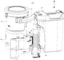
- FIG. 1is a schematic structural diagram of an embodiment of a base station of the present application
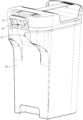
- FIG. 2is a schematic diagram of the structure of the base station of the present application without the body;
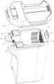
- FIG. 3is a schematic cross-sectional view of the base station of the present application without the body;
- Fig. 4is a schematic diagram of the assembly structure of the first box body and the second box body in Fig. 2;
- Fig. 5is a perspective view schematic diagram of the explosion structure of the second box body in Fig. 4;
- Fig. 6is another perspective schematic view of the explosive structure of the second box in Fig. 4;
- Fig. 7is a schematic diagram of the exploded structure of the first box and the second box in Fig. 5;
- Fig. 8is a schematic diagram of the exploded structure of the first box in Fig. 7;
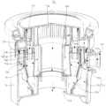
- Fig. 9is a schematic sectional view of the cyclone separator in Fig. 2;
- Fig. 10is a structural schematic view of a cyclone part in Fig. 9;
- Fig. 11is a schematic view of the structure of the cyclone part in Fig. 9;
- Fig. 12is a schematic diagram of the explosion structure of the cyclone part in Fig. 10;
- Fig. 13is a structural schematic diagram of the pre-swirl structure of the cyclone part in Fig. 12 .
- connectionand “fixation” should be understood broadly, for example, “fixation” can be a fixed connection, a detachable connection, or an integral body; It can be a mechanical connection or an electrical connection; it can be a direct connection or an indirect connection through an intermediary, and it can be an internal communication between two elements or an interaction relationship between two elements, unless otherwise clearly defined.
- fixingcan be a fixed connection, a detachable connection, or an integral body; It can be a mechanical connection or an electrical connection; it can be a direct connection or an indirect connection through an intermediary, and it can be an internal communication between two elements or an interaction relationship between two elements, unless otherwise clearly defined.
- the base station 100includes a first box 30 , a second box 50 , a cyclone separator 70 and a fan 90 .
- the first box body 30is provided with a sewage inlet 31, and the sewage inlet port 31 is used for entering solid-liquid mixed garbage;
- the second box body 50is connected to the first box body 30, and the second box body 50 is used for supplying the first box body
- the liquid garbage in 30enters;
- the cyclone separator 70is connected to the first box body 30;
- the fan 90is connected to the cyclone separator 70, and the fan 90 is used to drive the external air flow into the first box body 30 from the sewage inlet 31, and can After passing through the cyclone separator 70, it enters the fan 90, so that the solid-liquid mixed garbage enters the first box body 30 through the sewage inlet 31.
- the base station 100may further include an organic body 10, and the body 10 may be roughly in the shape of a cuboid, so that its shape is relatively regular and easy to process and shape.
- the first box body 30 , the second box body 50 , the cyclone separator 70 and the fan 90can all be installed in the machine body 10 , so that various components of the base station 100 can be assembled to form a whole.
- the side wall of the lower end of the body 10can be recessed to form a docking cavity 11 for the entry and docking of a cleaning device (also called a sweeping robot or a floor washing machine, etc.), and then the base station 100 can be docked in the docking cavity 11
- the cleaning device in the base stationperforms dust collection and suction, that is, the dirt inlet 31 of the base station 100 is connected with the dust collection box in the cleaning device, and at the same time, the fan 90 of the base station 100 is started for suction.
- the first box body 30can be used for accommodating the mixed solid-liquid garbage (that is, the mixture of solid garbage and liquid garbage) entering from the dirt inlet 31, so as to realize the preliminary transfer of the garbage in the dust box of the cleaning device.
- the first box body 30can be roughly square in shape, so that its shape is relatively regular and convenient for processing and molding.
- the present applicationis not limited thereto, and in other embodiments, the first box body 30 may also have a circular structure or other shapes.
- the second box body 50can be used for the liquid garbage in the first box body 30 to enter, so that the solid-liquid mixed garbage in the first box body 30 only stays in solid garbage, thereby realizing the collection of solid garbage in the first box body 30 Internal and liquid garbage are collected in the second box body 50 to complete the preliminary separation of solid garbage and liquid garbage.
- the second box body 50can also be roughly square, so that its shape is relatively regular and convenient for processing and manufacturing.
- the second box body 50may also have a circular structure or other shapes.
- the cyclone separator 70can be used to communicate with the first box body 30, so that the airflow after passing through the first box body 30 can pass through the cyclone separator 70 subsequently.
- the cyclone separator 70can make the incoming air flow rotate at a high speed to generate a centrifugal force, by which the water vapor or dust mixed in the air flow can be thrown to the side wall or the bottom wall of the air flow passage 53 of the cyclone separator 70, so as to Realize the separation of water vapor and dust entrained in the airflow.
- the fan 90can be used to provide airflow power, and the airflow driven outside can pass through the cyclone separator 70 of the first box 30 and the fan 90 in sequence, and finally the fan 90 is discharged to the outside, and the negative pressure is generated at the sewage inlet 31. Suction of solid-liquid mixed garbage in the dust collection box of the cleaning device.
- the blower fan 90can be activated to drive the external airflow into the first box body 30 from the sewage inlet 31, and then enter the fan after passing through the cyclone separator 70. Within 90. At this time, a negative pressure is formed at the dust inlet of the first box body 30 to suck the solid-liquid mixed garbage collected in the dirt collection box of the cleaning device. After that, after the solid-liquid mixture enters the first box body 30 with the airflow, the solid garbage can stay in the box body for collection, and the liquid garbage can enter the second box body 50 for collection, thereby realizing the preliminary collection of solid garbage and Liquid waste is separated.
- the airflowcan enter the cyclone separator 70.
- the airflowrotates at a high speed in the cyclone separator 70 to generate centrifugal force.
- centrifugal forcewater vapor and some water vapor and dust mixed in the airflow can be thrown into the cyclone separator 70.
- the side wall or the bottom wall of the airflow channel 53is collected; or the water vapor is fully vaporized, thereby realizing the separation of water vapor, airflow and dust again.
- the base station 100 in this solutioncan collect solid waste through the first box 30, liquid garbage through the second box 50, and separate and collect water vapor and dust through the cyclone separator 70 during operation.
- the base station 100can effectively separate the sewage mixed in the garbage collected by the cleaning device, so that the base station 100 only has air in the subsequent air duct after the cyclone separator 70, thereby reducing the water vapor in the base station 100.
- mildewwill occur to produce peculiar smell, and it may enter into the fan 90 of the base station 100 and affect the working life of the fan 90.
- the first box body 30is arranged in the second box body 50, and the second box body 50 is provided with a sewage outlet at a position corresponding to the sewage inlet port 31. 51.
- the sewage outlet 51is used for solid-liquid mixed garbage to enter the sewage inlet 31.
- the first box body 30is also provided with a transition port 33 connected to the second box body 50.
- the transition port 33is used for the first box body The liquid garbage and airflow in 30 enter into the second box body 50;
- the first box body 30is arranged in the second box body 50, and the cyclone separator 70 and the fan 90 are all arranged outside the second box body 50 (that is, the cyclone separator 70 passes through the second box body 50 is indirectly connected to the first box body 30), so that while ensuring that the installation between the two is relatively compact, it also ensures that the second box body 50 has a relatively large accommodating space. A relatively large holding capacity for liquid waste can be guaranteed. At the same time, such an arrangement does not require waterproof protection for the fan 90 , which is beneficial to improving the convenience of manufacturing the base station 100 .
- the side wall of the first box body 30 provided with the sewage inlet 31can abut against the side wall of the second box body 50 provided with the sewage outlet 51, so that the communication between the sewage outlet 51 and the sewage inlet 31 can be relatively convenient.
- the first box body 30may have a gap with the entire inner bottom wall of the second box body 50 so as to form a space for collecting liquid garbage.
- the first box body 30may also have a gap with a part of the inner bottom wall of the second box body 50, and at this time, another part of the inner bottom wall of the second box body 50 that is not in contact with the first box body 30 may be formed as a depression. Space for collecting liquid waste.
- the present applicationis not limited thereto.
- the cyclone separator 70 in this applicationmay also be directly arranged in the first box body 30.
- the first box body 30is separated and formed for The space for accommodating the cyclone separator 70 is sufficient, and the space can also be connected to the second box body 50, so that the airflow can enter the first box body again after passing through the first box body 30 and the second box body 50 in sequence 30 for accommodating the cyclone separator 70 and enters the cyclone separator 70.
- the first box body 30may also be arranged outside the second box body 50 similarly to the cyclone separator 70 and the fan 90 . At this time, the cyclone separator 70 may be directly connected to the first box body 30 .
- the cyclone separator 70 and the fan 90are arranged on the same side of the second box body 50 in the horizontal direction, and the cyclone separator 70 and the fan 90 are distributed sequentially in the up and down direction .
- the cyclone separator 70 and the fan 90are arranged on the same side of the second box body 50 and arranged in a stacked manner. At this time, the cyclone separator 70 and the blower fan 90 can also be distributed more compactly, which is conducive to further improving the compactness of the installation of the first box body 30, the second box body 50, the cyclone separator 70 and the blower fan 90.
- the overall volume of the base station 100is reduced.
- the present applicationis not limited thereto. In other embodiments, when there is a relatively large accommodation space in the body 10 of the base station 100, the cyclone separator 70 and the fan 90 may also be arranged in a horizontal direction. set side by side.
- the base station 100further includes a sewage suction pipe 60, which is arranged outside the second box body 50, and one end of the sewage suction pipe 60 is connected to Sewage outlet 51.
- the dirt suction pipe 60is set so that the end of the dirt suction pipe 60 away from the dirt outlet 51 can be used to communicate with the dust collection box of the cleaning device, thereby improving the connection between the dust collection box of the cleaning device and the base station 100.
- the convenience of connectingat the same time, the structure of the sewage suction pipe 60 is relatively simple, which can simplify the communication channel between the base station 100 and the cleaning device.
- the sewage outlet 51may be arranged above the second box body 50 to further increase the holding capacity of the second box body 50 for liquid garbage. At this time, the sewage suction pipe 60 may be extended in the vertical direction.
- the sewage suction pipe 60can be detachably connected to the outside of the sewage outlet 51, or part of the structure of the sewage suction pipe 60 can be detachably inserted into the sewage outlet. within 51.
- the base station 100further includes a first filter 331 , and the first filter 331 is disposed at the transition opening 33 .
- the solid-liquid mixed garbage in the first box body 30can be filtered and intercepted through the first filter element 331, so that the solid garbage can be retained in the first box body 30, while the liquid garbage and the air flow can be filtered and intercepted. Pass through the transition port 33 .
- the area of the transition port 33can be set relatively large to facilitate processing, and the first filter element 331 can be a filter screen or a filter element directly on the market. Purchased components are beneficial to improve the convenience of manufacturing the base station 100 .
- the present applicationis not limited thereto.
- the first filter element 331when the area of the transition opening 33 is relatively small, the first filter element 331 is not provided at this time, and the first filter element 331 is directly passed through the transition opening. 33 is also possible to filter and intercept.
- the shape of the relief opening 33can be rectangular or rectangular, so as to improve the convenience of processing and forming the relief opening 33 .
- the quantity of the crossing opening 33can be one, also can be two or more etc. certainly.
- the top wall of the second box body 50is provided with an air flow channel 53 , and the channel outlet 54 of the air flow channel 53 communicates with Cyclone separator 70;
- the front side wall of the first box body 30is provided with a sewage inlet 31, and the bottom wall of the first box body 30 and the rear side wall, left side wall and right side wall of the first box body 30 are all provided with a Allow the opening 33, so that the air flow flows out from the opening 33 on the bottom wall, the rear side wall, the left side wall and the right side wall of the first box body 30 and then flows to the front side, and then flows upwards into the air flow passage 53 and is passed through the passage.
- the outlet 54enters the cyclone separator 70; the number of the first filter element 331 is multiple, and each first filter element 331 is arranged outside the transition port 33 on the same wall surface of the first box body 30, and the plurality of first filter elements 331
- the sum of the flow areas of a filter element 331is not less than the area of the dirt inlet 31 .
- the bottom wall, the rear side wall, the left side wall and the right side wall of the first box body 30are all provided with a gap 33 (wherein, the front, rear, left, and right sides of the first box body 30 are in relative positional relationship, That is to say, the bottom wall of the first box body 30 and the side wall not provided with the sewage inlet 31 are both provided with a relief port 33 ), so that the number of the relief ports 33 is relatively large.
- the liquid garbage and the airflow in the first box body 30can pass through multiple directions towards the bottom wall of the first box body 30 and the side wall of the first box body 30 that is not provided with the sewage inlet 31, thereby facilitating The dust collection efficiency of the base station 100 to the cleaning device is greatly improved.
- the air flow channel 53is arranged on the top wall of the second box body 50, so that the air flow can flow upwards after flowing out from the transition port 33 of the first box body 30, and the liquid rubbish can flow upward after passing through the first box body 30. Let the port 33 flow out and drop down, which is beneficial to the separation between the airflow and the liquid waste and further improves the holding capacity of the second box 50 for the liquid waste.
- the channel outlet 54 of the air flow channel 53 and the sewage outlet 51are arranged on the same side, in other words, the channel outlet 54 is arranged on the front side of the second box body 50, so that the air flow can flow from the first box body 30 After the bottom wall and the side wall let the mouth 33 flow out, it can flow to one side of the airflow channel 53 in a circuitous manner.
- the specific airflow flow pathcan be combined with reference to the flow direction indicated by the dashed arrow in FIG. 3 and FIG.
- the airflowis from the first The bottom wall, the rear side wall, the left side wall and the right side wall of a box body 30 flow out of the transition port 33 and then flow forward, then flow upward and pass through the first box body 30 corresponding to the airflow of the second box body 50
- the channel 53avoids the opening 34 and enters the airflow channel 53 , and finally flows out of the second box body 50 through the channel outlet 54 of the airflow channel 53 and enters the subsequent cyclone separator 70 .
- the circuitous flow of the airflowprolongs the flow path of the airflow, so that the airflow and the liquid garbage have sufficient separation time, thereby further improving the separation effect between the airflow and the liquid garbage.
- each first filter element 331is located outside the transition opening 33 on the same wall surface of the first casing 30, so that there are two transition openings 33 or more on the same wall surface on the first casing 30 When passing through the opening 33, only one first filter 331 can be installed to cover two or more openings 33 on the wall at the same time, which is beneficial to improve the installation efficiency.
- the first filter element 331is also arranged on the outer wall of the first box body 30, so that the installation is not limited by the inner space of the first box body 30, which is beneficial to further improve the convenience of installation.
- the sum of the flow areas of the plurality of first filter elements 331is not less than the area of the dirt inlet 31, which is also conducive to improving the efficiency of the airflow flowing out from the first box body 30, thereby improving the dust collection and suction of the cleaning device by the base station 100. Pollution efficiency.
- the present applicationis not limited thereto, and in other embodiments, it is also possible for one first filter element 331 to cover only one transition port 33 .
- first box body 30can also be provided with a relief port 33 only on the bottom wall, or only the side wall is provided with a relief port 33, which can ensure that the liquid garbage and air flow in the first box body 30 can Just pass through and enter the second box body 50 .
- the upper end of the first box body 30is open, and the top wall of the second box body 50 covers the opening of the first box body 30 . mouth.
- the upper end of the first box body 30is set in an open shape, so that the first box body 30 only has a bottom wall and side walls surrounding the bottom wall.
- the structure of the first box body 30is relatively simple, which is beneficial to improve the convenience of processing and forming the first box body 30 .
- such settingcan also facilitate the user to take out and clean up the solid waste stagnated in the first box body 30 .
- the top wall of the second box body 50can be opened so that the first box body 30 is exposed when the second box body 50 is opened.
- the present applicationis not limited thereto.
- the first box body 30may also have a top wall, and in order to facilitate the removal of solid waste in the first box body 30, the first box body 30 The top wall of the box body 30 may be provided with an opening for taking out the garbage.
- the second tank 50communicates with the cyclone separator 70 through a connecting pipe 55 .
- the second box body 50 and the cyclone separator 70are respectively connected through opposite ends of the connecting pipe 55, so that the second box body 50 and the air separation can be communicated more conveniently.
- the installation of the second box body 50 and the cyclone separator 70 at their respective preset installation positionsis not affected by the communication relationship between the two.
- the end of the connecting pipe 55 away from the cyclone separator 70communicates with the channel outlet 54 of the air flow channel 53 .
- the airflow in the airflow channel 53enters the connecting pipe 55 after flowing out of the second box body 50 from the channel outlet 54 , and then enters the cyclone separator 70 through the end of the connecting pipe 55 away from the channel outlet 54 .
- the end of the connecting pipe 55 far away from the cyclone separator 70may be connected to the outside of the channel outlet 54 , and of course the part of the end of the connecting pipe 55 away from the cyclone separator 70 may be directly inserted into the channel outlet 54 .
- a net bag 35is provided in the first box body 30 , and one end of the net bag 35 is formed with an opening. There are 31 sewage inlets.
- the net bag 35can also filter and intercept the solids in the solid-liquid mixed garbage entering from the sewage inlet 31, which is beneficial to further improve the effect of filtering and intercepting solid garbage.
- the usercan also directly take out the net bag 35, so that the collected solid waste can be quickly taken out more conveniently, which is beneficial to improve The user's experience in using the base station 100 .
- one end of the mesh bag 35 with an openingis clamped and fixed to the first box body 30 .
- the mesh bag 35is clamped and fixed with the first box body 30, so that the connection relationship between the two is simplified, which is conducive to improving the convenience of installing and removing the mesh bag 35 in the first box body 30 . Simultaneously, when the net bag 35 is taken off, the net bag 35 will not be damaged, which is beneficial to ensure that the net bag 35 can stably collect and accommodate solid waste.
- the mesh bag 35may also be fixed in the first box body 30 by bonding or other methods.
- the cyclone separator 70includes an outer casing 71 and a cyclone portion 73.
- An accommodating chamber 711is formed in the outer casing 71.
- the outer casing 71is also provided with a communication chamber.
- the cyclone part 73is arranged in the accommodation chamber 711, and the cyclone part 73 includes a plurality of Cyclone cone barrel 731 and cyclone cover body 733, a plurality of cyclone cone barrels 731 are arranged around the circumference of the outer shell 71, and the larger ends of the cross-sections of the plurality of cyclone cone barrels 731 are all facing upward, and the cyclone cover body 733 is located
- the upper end of a plurality of cyclone cone barrels 731; the upper wall of the cyclone cover 733 and the part of the cavity wall of the accommodating cavity 711form an air outlet cavity 735, and the cyclone cover 733 is provided with a plurality of air passages 737, and each air passage 737 is Connected to the outlet chamber 735 and a
- the cyclone portion 73includes a plurality of cyclone cone barrels 731, so that the airflow can pass through the plurality of cyclone cone barrels 731 for cyclone separation at the same time, which is beneficial to improve the detection of the inclusions in the airflow. Separation efficiency of water vapor and dust inside. And a plurality of cyclone cone barrels 731 are arranged around, and the air outlet pipe 739 passes through the middle of the plurality of cyclone cone barrels 731 to exhaust downwards.
- the air outlet 715is also correspondingly arranged on the bottom wall of the outer casing 71, thereby facilitating The communication between the cyclone separator 70 and the blower fan 90 distributed sequentially in the up and down direction is to improve the compactness of the distribution between them.
- the cyclone part 73may also include only one cyclone cone 731, and the air outlet 715 at this time may be arranged on the top of the outer shell 71. wall or sidewall.
- the cyclone part 73also includes a plurality of pre-rotation structures 74, each pre-rotation structure 74 is set corresponding to a cyclone cone 731, and the pre-rotation structure 74 includes an outer ring 741, an inner ring 743 and a flow guide Sheet 747, the end that outer ring 741 has opening is arranged on the upper end of cyclone cone barrel 731, and inner ring 743 is arranged in the outer ring 741, and surrounds with outer ring 741 to form the air gap 745 that communicates with cyclone cone barrel 731, the inner ring 743 is also connected to the air passage port 737; the deflector 747 is located in the air passage gap 745 (that is, between the outer ring 741 and the inner ring 743), and is connected to the inner ring 743 and the outer ring 741 to form an integrated structure.
- the flow sheet 747extends helically along the circumferential direction of the pre-rotation structure
- both the inner ring 743 and the outer ring 741are cylindrical structures with openings at both ends, and are nested with each other. And one end of the outer ring 741 is arranged on the upper end of the cyclone cone 731 to facilitate the communication between the air gap 745 between the outer ring 741 and the inner ring 743 and the cyclone cone 731 .
- the air gap 745is formed through the gap between the outer ring 741 and the inner ring 743 , so that the cyclone part 73 can realize the air intake from the top of the cyclone part 73 downward.
- the airflowcan be fed downwards in the circumferential direction of the cyclone part 73 , which is beneficial to increase the intake air volume and improve the separation efficiency of the airflow by the cyclone part 73 .
- the airflow entering the air gap 745can be better guided by the deflector 747 to ensure that the airflow can perform high-speed rotational movement in the cyclone part 73, thereby improving the separation effect of the cyclone part 73 on the airflow.
- the outer ring 741 and the inner ring 743are connected by a deflector 747 , so that the outer ring 741 and the inner ring 743 form an integral structure.
- every two adjacent cyclone cones 731 in the plurality of cyclone cones 731may also have a connection relationship so that the plurality of cyclone cones 731 are connected into an integral structure
- in the plurality of pre-swirling structures 74may also be Every two adjacent outer rings 741 have a connection relationship so that multiple pre-rotation structures are connected into an integral structure, so as to further improve the convenience of assembling the cyclone part 73 .
- the pre-swirling structure 74only has the inner ring 743 and the deflector 747, and it is also possible for the deflector 747 to be arranged between the inner ring 743 and the cyclone cone 731 .
- a second filter element 736is provided in the air outlet chamber 735, and the second filter element 736 is arranged in a ring shape, and surrounds the outside of the air outlet pipe 739 and is located at a plurality of air outlets The inside of the 737.
- the airflow in the air outlet chamber 735can be further filtered through the filter element, which is beneficial to further improve the separation effect on the water vapor and dust mixed in the airflow.
- the second filter element 736may be a filter net or a filter element.
- the cyclone separator 70also includes an inner casing 75, the inner casing 75 is an annular structure with openings at both ends, and the inner casing 75 surrounds the outside of a plurality of cyclone cone barrels 731; the inner casing The body 75 divides the space of the accommodating cavity 711 at the side of the cyclone cover 733 facing the cyclone cone 731 to form an inner cavity 751 and an outer cavity 753 surrounding the inner cavity 751.
- the side peripheral surface of the inner casing 75is provided with There is a filter hole 755 connecting the outer cavity 753 and the inner cavity 751 .
- the airflow entering the accommodating cavity 711 from the air inlet 713needs to pass through the filter hole 755 of the inner housing 75 before entering the cyclone portion 73 .
- the arrangement of a plurality of filter holes 755 on the inner casing 75has a preliminary filtering effect on relatively large particles of garbage mixed in the airflow, so that the relatively large particles of garbage can be collected in the outer cavity 753, thereby realizing cyclone
- the separator 70pre-filters before the cyclone 73.
- the fan 90has a fan inlet 91 , and a third filter 719 is provided at the fan inlet 91 .
- the setting of the third filter element 719can further intercept and filter the airflow entering the fan 90 , so that water vapor and dust can be further prevented from entering the fan 90 .
- the third filter element 719may be a filter net or a filter element.
- the fan 90also has a fan outlet 93 , the fan inlet 91 can be arranged on the upper surface of the fan 90 , and the fan outlet 93 is arranged on the side surface of the fan 90 .
- the present applicationalso proposes a cleaning device, which includes a cleaning device and a base station 100.
- a cleaning devicewhich includes a cleaning device and a base station 100.
- the base station 100refers to the above-mentioned embodiments. Since this cleaning device adopts all the technical solutions of all the above-mentioned embodiments, it has at least the above-mentioned implementation All the beneficial effects brought by the technical solution of the example will not be repeated here.
- the cleaning devicemay also be called a sweeping robot or a washing machine.
Landscapes
- Cyclones (AREA)
Abstract
Description
Translated fromChinese优先权信息priority information
本申请要求于2021年12月30日申请的、申请号为202111662738.0以及202123439208.8的中国专利申请的优先权,其全部内容通过引用结合在本申请中。This application claims the priority of the Chinese patent applications with application numbers 202111662738.0 and 202123439208.8 filed on December 30, 2021, the entire contents of which are incorporated in this application by reference.
本申请涉及清洁设备技术领域,特别涉及一种基站和应用该基站的清洁设备。The present application relates to the technical field of cleaning equipment, in particular to a base station and cleaning equipment using the base station.
相关技术中的清洁设备包括有清洁装置和基站,该清洁装置可以用于对地面上固体垃圾或者液体垃圾进行收集,而基站可以用于对清洁装置所收集到的垃圾进行进一步地收集暂存。然而,由于清洁设备所收集的垃圾中一般夹杂有污水,并在被基站转移收集的过程中随之进入至基站内。之后该污水在基站内的后续风道内长时间滞留后容易发生霉变而产生异味,或者进入到基站的风机内而影响风机的工作寿命。The cleaning equipment in the related art includes a cleaning device and a base station. The cleaning device can be used to collect solid or liquid garbage on the ground, and the base station can be used to further collect and temporarily store the garbage collected by the cleaning device. However, because the garbage collected by the cleaning equipment is generally mixed with sewage, and then enters into the base station during the process of being transferred and collected by the base station. Afterwards, after the sewage stays in the follow-up air duct in the base station for a long time, it is prone to mildew and odor, or enters into the fan of the base station and affects the working life of the fan.
申请内容application content
本申请的主要目的是提供一种基站,旨在使其能够对从清洁装置所收集到的垃圾中夹杂的污水进行有效的分离出来,降低水汽在基站内的后续风道内长时间滞留后发生霉变而产生异味,和进入到基站的风机内而影响风机的工作寿命的可能。The main purpose of this application is to provide a base station, which can effectively separate the sewage mixed in the garbage collected from the cleaning device, and reduce the occurrence of mildew after the water vapor stays in the follow-up air duct in the base station for a long time. It may cause peculiar smell and enter the fan of the base station to affect the working life of the fan.
为实现上述目的,本申请提出的基站包括:In order to achieve the above purpose, the base station proposed in this application includes:
第一箱体,所述第一箱体设有进污口,所述进污口用于供固液混合垃圾进入;The first box, the first box is provided with a sewage inlet, and the sewage inlet is used for solid-liquid mixed garbage to enter;
第二箱体,所述第二箱体连通于所述第一箱体,所述第二箱体用于供所述第一箱体内的液体垃圾进入;a second box, the second box is connected to the first box, and the second box is used for liquid garbage in the first box to enter;
气旋分离器,所述气旋分离器连通于所述第一箱体;以及a cyclone separator, the cyclone separator communicated with the first box; and
风机,所述风机连通于所述气旋分离器,所述风机用于驱使外界气流由所述进污口进入所述第一箱体内,并可经所述气旋分离器后进入所述风机内,以使固液混合垃圾由所述进污口进入所述第一箱体内。A fan, the fan is connected to the cyclone separator, and the fan is used to drive the external airflow into the first box through the sewage inlet, and can enter the fan after passing through the cyclone separator, The solid-liquid mixed garbage enters the first box through the sewage inlet.
在一实施例中,所述第一箱体设于所述第二箱体内,所述第二箱体在对应所述进污口的位置设有过污口,所述过污口用于供固液混合垃圾进入所述进污口,所述第一箱体还设有连通所述第二箱体的过让口,所述过让口用于供所述第一箱体内的液体垃圾和气流进入所述第二箱体内;In one embodiment, the first box is arranged in the second box, and the second box is provided with a sewage outlet at a position corresponding to the sewage inlet, and the sewage outlet is used for supplying The solid-liquid mixed garbage enters the sewage inlet, and the first box body is also provided with a transition port that communicates with the second box body, and the transition port is used for the liquid garbage in the first box body and Air flow enters the second box;
所述气旋分离器和所述风机均设于所述第二箱体之外,且所述气旋分离器连通于所述第二箱体。Both the cyclone separator and the blower are arranged outside the second box, and the cyclone separator communicates with the second box.
在一实施例中,所述气旋分离器和所述风机设于所述第二箱体于水平方向上的同一侧,且所述气旋分离器和所述风机在上下方向上依次分布;In one embodiment, the cyclone separator and the fan are arranged on the same side of the second box in the horizontal direction, and the cyclone separator and the fan are distributed sequentially in the vertical direction;
且/或,所述基站还包括吸污管,所述吸污管设于所述第二箱体的外侧,且所述吸污管的一端连通于所述过污口。And/or, the base station further includes a sewage suction pipe, the sewage suction pipe is arranged outside the second box, and one end of the sewage suction pipe communicates with the sewage outlet.
在一实施例中,所述基站还包括第一过滤件,所述第一过滤件设于所述过让口。In one embodiment, the base station further includes a first filter element, and the first filter element is disposed at the transition port.
在一实施例中,所述第二箱体的顶壁设有气流通道,所述气流通道的通道出口连通于所述气旋分离器;In one embodiment, the top wall of the second box is provided with an air flow channel, and the channel outlet of the air flow channel is connected to the cyclone separator;
所述第一箱体的前侧壁设有所述进污口,所述第一箱体的底壁、后侧壁、左侧壁以及右侧壁均设有所述过让口,以使气流从所述第一箱体的底壁、后侧壁、左侧壁以及右侧壁上的所述过让口流出后流向前侧,之后向上流入所述气流通道内而由所述通道出口进入所述气旋分离器内;The front side wall of the first box body is provided with the sewage inlet, and the bottom wall, rear side wall, left side wall and right side wall of the first box body are all provided with the passage opening, so that The air flow flows out from the transition openings on the bottom wall, rear side wall, left side wall and right side wall of the first box and then flows to the front side, then flows upward into the air flow channel and exits from the channel. into the cyclone separator;
所述第一过滤件的数量为多个,每一个所述第一过滤件设于所述第一箱体的同壁面上 的所述过让口之外,且多个所述第一过滤件的过流面积的总和不小于所述进污口的面积。The number of the first filter elements is multiple, and each of the first filter elements is arranged outside the transition port on the same wall of the first box body, and a plurality of the first filter elements The sum of the overflow areas is not less than the area of the sewage inlet.
在一实施例中,所述第一箱体的上端呈敞口状设置,所述第二箱体的顶壁遮盖所述第一箱体的敞口;In one embodiment, the upper end of the first box is open, and the top wall of the second box covers the opening of the first box;
且/或,所述第二箱体和所述气旋分离器之间通过连接管连通。And/or, the second box communicates with the cyclone separator through a connecting pipe.
在一实施例中,所述第一箱体内设有网袋,所述网袋的一端形成有开口,所述网袋具有开口的一端安装于所述第一箱体的所述进污口处。In one embodiment, a mesh bag is provided in the first box, an opening is formed at one end of the mesh bag, and one end of the mesh bag with an opening is installed on the sewage inlet of the first box body place.
在一实施例中,所述网袋具有开口的一端卡接固定于所述第一箱体。In one embodiment, one end of the mesh bag having an opening is clamped and fixed to the first box body.
在一实施例中,所述气旋分离器包括:In one embodiment, the cyclone separator comprises:
外壳体,所述外壳体内形成有容置腔,所述外壳体还设有连通所述容置腔的进气口和出气口,所述进气口连通于所述第一箱体,所述出气口连通于所述风机;和An outer casing, an accommodating cavity is formed inside the outer casing, an air inlet and an air outlet communicating with the accommodating cavity are also provided in the outer casing, the air inlet is connected to the first box body, the the air outlet is connected to the fan; and
气旋部,所述气旋部设于所述容置腔内,所述气旋部包括多个气旋锥桶和气旋盖体,多个所述气旋锥桶沿所述外壳体的周向环绕设置,且多个所述气旋锥桶的横截面较大的一端均朝向上设置,所述气旋盖体位于多个所述气旋锥桶的上端;a cyclone part, the cyclone part is arranged in the accommodating cavity, the cyclone part includes a plurality of cyclone cones and a cyclone cover, and the plurality of cyclone cones are arranged around the circumference of the outer shell, and The ends with larger cross-sections of the plurality of cyclone cones are all facing upwards, and the cyclone cover is located at the upper end of the plurality of cyclone cones;
所述气旋盖体的上壁面和所述容置腔的部分腔壁围合形成出气腔,所述气旋盖体设有多个过气口,每一个所述过气口均连通于所述出气腔和一个所述气旋锥桶,所述气旋盖体还穿设有连通于所述出气腔的出气管,所述出气管向下延伸而位于多个所述气旋锥桶之间,所述出气管下端连通于所述出气口。The upper wall surface of the cyclone cover and part of the cavity wall of the accommodating cavity form an air outlet cavity, and the cyclone cover is provided with a plurality of gas outlets, and each of the gas outlets is connected to the outlet cavity and the air outlet. One of the cyclone cones, the cyclone cover is also pierced with an air outlet pipe connected to the air outlet chamber, the air outlet pipe extends downwards and is located between a plurality of the cyclone cones, the lower end of the air outlet pipe connected to the air outlet.
在一实施例中,所述气旋部还包括多个预旋结构,每一个所述预旋结构对应一个所述气旋锥桶设置,所述预旋结构包括外环、内环以及导流片,所述外环具有开口的一端设于所述气旋锥桶的上端,所述内环设于所述外环内,并和所述外环围合形成连通所述气旋锥桶的过气间隙,所述内环还连通于所述过气口;所述导流片设于所述过气间隙内,并连接于所述内环和所述外环而形成为一体结构,所述导流片沿所述预旋结构的周向呈螺旋延伸设置;In one embodiment, the cyclone part further includes a plurality of pre-swirling structures, each of which is set corresponding to one of the cyclone cones, and the pre-swirling structures include an outer ring, an inner ring and a deflector, One end of the outer ring having an opening is arranged on the upper end of the cyclone cone, the inner ring is arranged inside the outer ring, and is enclosed with the outer ring to form an air gap communicating with the cyclone cone, The inner ring is also connected to the air passage port; the guide vane is arranged in the air passage gap, and is connected to the inner ring and the outer ring to form an integrated structure, and the guide vane is along the The circumferential direction of the pre-rotation structure is arranged in a helical extension;
且/或,所述出气腔内设有第二过滤件,所述第二过滤件呈环形状设置,并环绕于所述出气管的外侧和位于多个所述过气口的内侧;And/or, a second filter element is provided in the air outlet chamber, the second filter element is arranged in a ring shape, and surrounds the outside of the air outlet pipe and is located inside a plurality of the air outlets;
且/或,所述气旋分离器还包括内壳体,所述内壳体为两端具有开口的环形结构,所述内壳体环绕于多个所述气旋锥桶的外侧;所述内壳体将所述容置腔位于所述气旋盖体面向所述气旋锥桶的一侧的空间分隔形成内腔体和环绕于所述内腔体的外腔体,所述内壳体的侧周面设有连通所述外腔体和所述内腔体的过滤孔。And/or, the cyclone separator also includes an inner casing, the inner casing is an annular structure with openings at both ends, and the inner casing surrounds the outer sides of a plurality of the cyclone cone barrels; the inner casing body separates the accommodating cavity at the side of the cyclone cover facing the cyclone cone to form an inner cavity and an outer cavity surrounding the inner cavity, and the side circumference of the inner casing The surface is provided with filter holes connecting the outer cavity and the inner cavity.
在一实施例中,所述风机具有风机进风口,所述风机进风口处设有第三过滤件。In one embodiment, the fan has an air inlet of the fan, and a third filter element is arranged at the air inlet of the fan.
本申请还提出一种清洁设备,包括:The application also proposes a cleaning device, comprising:
清洁装置;和cleaning device; and
基站,所述基站包括第一箱体、第二箱体、气旋分离器以及风机,所述第一箱体设有进污口,所述进污口用于供固液混合垃圾进入;所述第二箱体连通于所述第一箱体,所述第二箱体用于供所述第一箱体内的液体垃圾进入;所述气旋分离器连通于所述第一箱体;所述风机连通于所述气旋分离器,所述风机用于驱使外界气流由所述进污口进入所述第一箱体内,并可经所述气旋分离器后进入所述风机内,以使固液混合垃圾由所述进污口进入所述第一箱体内。The base station, the base station includes a first box, a second box, a cyclone separator and a fan, the first box is provided with a sewage inlet, and the sewage inlet is used for solid-liquid mixed garbage to enter; the The second box communicates with the first box, and the second box is used for the liquid garbage in the first box to enter; the cyclone separator communicates with the first box; the fan Connected to the cyclone separator, the fan is used to drive the external airflow into the first box from the sewage inlet, and can enter the fan after passing through the cyclone separator, so that the solid-liquid mixture Garbage enters the first box through the sewage inlet.
本申请的技术方案的基站在对清洁装置进行集尘抽污时,启动风机可以驱使驱使外界气流由进污口进入第一箱体内,并可经气旋分离器后进入风机内。此时,第一箱体的进尘口处形成负压而可以对清洁装置的集污盒内所收集到的固液混合垃圾进行抽吸。之后在固液混合物随气流进入到第一箱体内后,固体垃圾能够滞留于箱体内进行收集,而液体垃圾能够进入到第二箱体内进行收集,从而实现了初步对固体垃圾和液体垃圾进行分离。之后气流能够进入到气旋分离器内,此时气流在气旋分离器内作高速旋转而产生离心力,通过该离心力可以将水汽和一些夹杂于气流内的水汽和灰尘甩到气旋分离器内的气流通道的 侧壁或者底壁上进行收集;或者是将水汽充分汽化掉,从而实现了再次对水汽、气流以及灰尘进行分离。When the base station of the technical solution of the present application collects dust and sucks the cleaning device, the blower is activated to drive the external airflow into the first box through the dirt inlet, and enter the blower after passing through the cyclone separator. At this time, a negative pressure is formed at the dust inlet of the first box to suck the solid-liquid mixed garbage collected in the dirt collection box of the cleaning device. After the solid-liquid mixture enters the first box with the airflow, the solid garbage can stay in the box for collection, while the liquid garbage can enter the second box for collection, thus realizing the preliminary separation of solid garbage and liquid garbage . Afterwards, the airflow can enter the cyclone separator. At this time, the airflow rotates at a high speed in the cyclone separator to generate centrifugal force. Through this centrifugal force, water vapor and some water vapor and dust mixed in the airflow can be thrown to the airflow channel in the cyclone separator. Collect on the side wall or bottom wall; or fully vaporize the water vapor, so as to realize the separation of water vapor, airflow and dust again.
因此,本方案中的基站在工作时可以通过第一箱体对固体垃圾进行收集、通过第二箱体对液体垃圾进行收集、以及通过气旋分离器对水汽和灰尘进行再次分离收集,如此实现了基站能够对从清洁装置所收集到的垃圾中夹杂的污水进行有效的分离出来,使得基站在气旋分离器之后的后续风道内仅具有空气,从而降低水汽在基站内的后续风道内长时间滞留后发生霉变而产生异味,和进入到基站的风机内而影响风机的工作寿命的可能。Therefore, the base station in this solution can collect solid garbage through the first box, collect liquid garbage through the second box, and separate and collect water vapor and dust through the cyclone separator during operation, thus realizing The base station can effectively separate the sewage mixed with the garbage collected from the cleaning device, so that the base station only has air in the follow-up air duct after the cyclone separator, thereby reducing the water vapor after a long time staying in the follow-up air duct in the base station. Mildew may cause peculiar smell, and may enter the fan of the base station and affect the working life of the fan.
为了更清楚地说明本申请实施例或现有技术中的技术方案,下面将对实施例或现有技术描述中所需要使用的附图作简单地介绍,显而易见地,下面描述中的附图仅仅是本申请的一些实施例,对于本领域普通技术人员来讲,在不付出创造性劳动的前提下,还可以根据这些附图示出的结构获得其他的附图。In order to more clearly illustrate the technical solutions in the embodiments of the present application or the prior art, the following will briefly introduce the drawings that need to be used in the description of the embodiments or the prior art. Obviously, the accompanying drawings in the following description are only These are some embodiments of the present application, and those skilled in the art can also obtain other drawings according to the structures shown in these drawings without creative effort.
图1为本申请基站一实施例的结构示意图;FIG. 1 is a schematic structural diagram of an embodiment of a base station of the present application;
图2为本申请基站去掉机体的结构示意图;FIG. 2 is a schematic diagram of the structure of the base station of the present application without the body;
图3为本申请基站去掉机体的一剖面示意图;FIG. 3 is a schematic cross-sectional view of the base station of the present application without the body;
图4为图2中的第一箱体和第二箱体的组装结构示意图;Fig. 4 is a schematic diagram of the assembly structure of the first box body and the second box body in Fig. 2;
图5为图4中第二箱体的爆炸结构的一视角示意图;Fig. 5 is a perspective view schematic diagram of the explosion structure of the second box body in Fig. 4;
图6为图4中第二箱体的爆炸结构的另一视角示意图;Fig. 6 is another perspective schematic view of the explosive structure of the second box in Fig. 4;
图7为图5中第一箱体和第二箱体的爆炸结构示意图;Fig. 7 is a schematic diagram of the exploded structure of the first box and the second box in Fig. 5;
图8为图7中第一箱体的爆炸结构示意图;Fig. 8 is a schematic diagram of the exploded structure of the first box in Fig. 7;
图9为图2中气旋分离器的一剖面示意图;Fig. 9 is a schematic sectional view of the cyclone separator in Fig. 2;
图10为图9中气旋部一视角的结构示意图;Fig. 10 is a structural schematic view of a cyclone part in Fig. 9;
图11为图9中气旋部一视角的结构示意图;Fig. 11 is a schematic view of the structure of the cyclone part in Fig. 9;
图12为图10中气旋部的爆炸结构示意图;Fig. 12 is a schematic diagram of the explosion structure of the cyclone part in Fig. 10;
图13为图12中气旋部的预旋结构的结构示意图。Fig. 13 is a structural schematic diagram of the pre-swirl structure of the cyclone part in Fig. 12 .
附图标号说明:Explanation of reference numbers:
本申请目的的实现、功能特点及优点将结合实施例,参照附图做进一步说明。The realization, functional features and advantages of the present application will be further described in conjunction with the embodiments and with reference to the accompanying drawings.
下面将结合本申请实施例中的附图,对本申请实施例中的技术方案进行清楚、完整地描述,显然,所描述的实施例仅仅是本申请的一部分实施例,而不是全部的实施例。基于本申请中的实施例,本领域普通技术人员在没有作出创造性劳动前提下所获得的所有其他实施例,都属于本申请保护的范围。The following will clearly and completely describe the technical solutions in the embodiments of the present application with reference to the accompanying drawings in the embodiments of the present application. Obviously, the described embodiments are only part of the embodiments of the present application, not all of them. Based on the embodiments in this application, all other embodiments obtained by persons of ordinary skill in the art without creative efforts fall within the protection scope of this application.
需要说明,本申请实施例中所有方向性指示(诸如上、下、左、右、前、后……)仅用于解释在某一特定姿态(如附图所示)下各部件之间的相对位置关系、运动情况等,如果该特定姿态发生改变时,则该方向性指示也相应地随之改变。It should be noted that all directional indications (such as up, down, left, right, front, back...) in the embodiments of the present application are only used to explain the relationship between the components in a certain posture (as shown in the drawings). Relative positional relationship, movement conditions, etc., if the specific posture changes, the directional indication will also change accordingly.
在本申请中,除非另有明确的规定和限定,术语“连接”、“固定”等应做广义理解,例如,“固定”可以是固定连接,也可以是可拆卸连接,或成一体;可以是机械连接,也可以是电连接;可以是直接相连,也可以通过中间媒介间接相连,可以是两个元件内部的连通或两个元件的相互作用关系,除非另有明确的限定。对于本领域的普通技术人员而言,可以根据具体情况理解上述术语在本申请中的具体含义。In this application, unless otherwise clearly specified and limited, the terms "connection" and "fixation" should be understood broadly, for example, "fixation" can be a fixed connection, a detachable connection, or an integral body; It can be a mechanical connection or an electrical connection; it can be a direct connection or an indirect connection through an intermediary, and it can be an internal communication between two elements or an interaction relationship between two elements, unless otherwise clearly defined. Those of ordinary skill in the art can understand the specific meanings of the above terms in this application according to specific situations.
另外,在本申请中涉及“第一”、“第二”等的描述仅用于描述目的,而不能理解为指示或暗示其相对重要性或者隐含指明所指示的技术特征的数量。由此,限定有“第一”、“第二”的特征可以明示或者隐含地包括至少一个该特征。另外,各个实施例之间的技术方案可以相互结合,但是必须是以本领域普通技术人员能够实现为基础,当技术方案的结合出现相互矛盾或无法实现时应当认为这种技术方案的结合不存在,也不在本申请要求的保护范围之内。In addition, the descriptions involving "first", "second" and so on in the present application are only for the purpose of description, and should not be understood as indicating or implying their relative importance or implicitly specifying the quantity of the indicated technical features. Thus, the features defined as "first" and "second" may explicitly or implicitly include at least one of these features. In addition, the technical solutions of the various embodiments can be combined with each other, but it must be based on the realization of those skilled in the art. When the combination of technical solutions is contradictory or cannot be realized, it should be considered that the combination of technical solutions does not exist , nor within the scope of protection required by the present application.
请结合参考图1至图3,本申请提出一种基站100。在本申请的一实施例中,该基站100包括第一箱体30、第二箱体50、气旋分离器70以及风机90。第一箱体30设有进污口31,进污口31用于供固液混合垃圾进入;第二箱体50连通于第一箱体30,第二箱体50用于供第一箱体30内的液体垃圾进入;气旋分离器70连通于第一箱体30;风机90连通于气旋分离器70,风机90用于驱使外界气流由进污口31进入第一箱体30内,并可经气旋分离器70后进入风机90内,以使固液混合垃圾由进污口31进入第一箱体30内。Please refer to FIG. 1 to FIG. 3 in combination. This application proposes a
在本申请的一实施例中,该基站100还可以包括有机体10,该机体10可以大致呈长方体结构,以使其形状相对较为规则而便于加工成型。此时,第一箱体30、第二箱体50、气旋分离器70以及风机90可以均安装于该机体10内,以便基站100的各个零部件可以组装形成一个整体。同时,该机体10的下端的侧壁可以凹陷形成一对接腔11,以供清洁装置(也可以称呼为扫地机器人或者洗地机等)的进入停靠,之后基站100可以对停靠在该对接腔11内的清洁装置进行集尘抽污,即基站100的进污口31与清洁装置内的集尘盒相连通,同时启动基站100的风机90进行抽吸。第一箱体30可以用于容置由进污口31进入的固液混合垃圾(即固体垃圾和液体垃圾混合物),实现将清洁装置的集尘盒内的垃圾的初步转移。其中,该第一箱体30可以大致为方形结构,以使其形状相对较为规则而便于加工成型制造。当然,本申请不限于此,于其他实施例中,该第一箱体30也可以为圆形结构或者其他形状结构等。第二箱体50可以用于供第一箱体30内的液体垃圾进入,使得第一箱体30内的固液混合垃圾仅滞留下固体垃圾,从而实现将固体垃圾收集于第一箱体30内、液体垃圾收集于第二箱体50内而完成固体垃圾和液体垃圾的初步分离。其中,该第二箱体50也可以大致为方形结构,以使其形状相对较为规则而便于加工成型制造。当然,本申请不限于此,于其他实施例中,该第二箱体50也可以为圆形结构或者其他形状结构等。气旋分离器70可以用于连通于第一箱体30,使得经过第一箱体30后的气流在 后续中可以经过气旋分离器70。而气旋分离器70可以使得进入的气流作高速旋转运动而产生离心力,通过该离心力可以将夹杂于气流内的水汽或者灰尘甩至气旋分离器70的气流通道53的侧壁或者底壁上,以实现对气流内夹杂的水汽和灰尘进行分离。其中,气旋分离器70的气旋分离原理为现有技术,故在此对气旋分离器70的具体结构不作详述。风机90可以用于提供气流动力,驱使外界的气流可以依次经过第一箱体30气旋分离器70以及风机90,最后由风机90再排出至外界,并使得进污口31处产生负压而实现对清洁装置的集尘盒内的固液混合垃圾的抽吸。In an embodiment of the present application, the
本申请的技术方案的基站100在对清洁装置进行集尘抽污时,启动风机90可以驱使驱使外界气流由进污口31进入第一箱体30内,并可经气旋分离器70后进入风机90内。此时,第一箱体30的进尘口处形成负压而可以对清洁装置的集污盒内所收集到的固液混合垃圾进行抽吸。之后在固液混合物随气流进入到第一箱体30内后,固体垃圾能够滞留于箱体内进行收集,而液体垃圾能够进入到第二箱体50内进行收集,从而实现了初步对固体垃圾和液体垃圾进行分离。之后气流能够进入到气旋分离器70内,此时气流在气旋分离器70内作高速旋转而产生离心力,通过该离心力可以将水汽和一些夹杂于气流内的水汽和灰尘甩到气旋分离器70内的气流通道53的侧壁或者底壁上进行收集;或者是将水汽充分汽化掉,从而实现了再次对水汽、气流以及灰尘进行分离。When the
因此,本方案中的基站100在工作时可以通过第一箱体30对固体垃圾进行收集、通过第二箱体50对液体垃圾进行收集、以及通过气旋分离器70对水汽和灰尘进行再次分离收集,如此实现了基站100能够对从清洁装置所收集到的垃圾中夹杂的污水进行有效的分离出来,使得基站100在气旋分离器70之后的后续风道内仅具有空气,从而降低水汽在基站100内的后续风道内长时间滞留后发生霉变而产生异味,和进入到基站100的风机90内而影响风机90的工作寿命的可能。Therefore, the
请结合参考图2至图7,在本申请的一实施例中,第一箱体30设于第二箱体50内,第二箱体50在对应进污口31的位置设有过污口51,过污口51用于供固液混合垃圾进入进污口31,第一箱体30还设有连通第二箱体50的过让口33,过让口33用于供第一箱体30内的液体垃圾和气流进入第二箱体50内;气旋分离器70和风机90均设于第二箱体50之外,且气旋分离器70连通于第二箱体50。Please refer to FIG. 2 to FIG. 7. In one embodiment of the present application, the
在本实施例中,将第一箱体30设置在第二箱体50内,而气旋分离器70和风机90均设置在第二箱体50之外(即气旋分离器70通过第二箱体50间接的连通于第一箱体30),使得在保证几者之间可以安装的相对较为紧凑的同时,也较大幅度的保证了第二箱体50内具有相对较大的容置空间而可以保证对液体垃圾具有相对较大的容纳量。同时,如此设置也无需对风机90进行防水保护,从而有利于提高该基站100制造的便利性。其中,第一箱体30设有进污口31的侧壁可以抵接第二箱体50设有过污口51的侧壁,以便过污口51和进污口31两者连通的可以较为便利。同时,第一箱体30可以与第二箱体50的整个内底壁均具有间隙,以便形成用于收集液体垃圾的空间。当然,第一箱体30也可以是与第二箱体50的部分内底壁具有间隙,此时第二箱体50的未抵接于第一箱体30的另一部分内底壁可以凹陷形成用于收集液体垃圾的空间。另外,需要说明的是,本申请不限于此,于其他实施例中,本申请中气旋分离器70也可以是直接设置在第一箱体30内,此时第一箱体30分隔形成用于容置该气旋分离器70的空间即可,同时空间还可以连通于第二箱体50,以便气流在依次经过第一箱体30和第二箱体50后,可以再次进入到第一箱体30的用于容置气旋分离器70的空间内而进入到气旋分离器70内。而在另一实施例中,第一箱体30也可以是类似气旋分离器70和风机90而设置在第二箱体50的外面。此时,气旋分离器70可以直接连通于第一箱体30。In this embodiment, the
请参考图2,在本申请的一实施例中,气旋分离器70和风机90设于第二箱体50于水平方向上的同一侧,且气旋分离器70和风机90在上下方向上依次分布。Please refer to Fig. 2, in one embodiment of the present application, the
在本实施例中,将气旋分离器70和风机90设置在第二箱体50的同一侧,并呈堆叠分布。此时,该气旋分离器70和风机90也可以分布的较为紧凑,从而有利于进一步地提高第一箱体30、第二箱体50、气旋分离器70以及风机90安装的紧凑性,以边缩小基站100的整体体积。当然,需要说明的是,本申请不限于此,于其他实施例中,在基站100的机体10内具有相对较大的容置空间时,该气旋分离器70和风机90也可以是在水平方向上呈并排设置。In this embodiment, the
请结合参考图2和图3,在本申请的一实施例中,基站100还包括吸污管60,吸污管60设于第二箱体50的外侧,且吸污管60的一端连通于过污口51。Please refer to FIG. 2 and FIG. 3 in combination. In an embodiment of the present application, the
在本实施例中,吸污管60的设置,使得通过吸污管60远离过污口51的一端可以用于连通于清洁装置的集尘盒,从而能够提高清洁装置的集尘盒与基站100相连通的便利性。同时,该吸污管60的结构又相对较为简单,能够简化基站100和清洁装置相连通的通道。其中,过污口51可以是设置第二箱体50的上方,以进一步地提高第二箱体50对液体垃圾的容纳量。此时,该吸污管60可以是在上下方向延伸设置。进一步地,为了提高后期清洗或者维修更换的便利性,该吸污管60可以是可拆卸地连通于过污口51的外侧,或者是吸污管60的部分结构可拆卸插设于过污口51内。In this embodiment, the
请结合参考图3、图7以及图8,在本申请的一实施例中,基站100还包括第一过滤件331,第一过滤件331设于过让口33。Please refer to FIG. 3 , FIG. 7 and FIG. 8 in combination. In an embodiment of the present application, the
在本实施例中,通过第一过滤件331可以对第一箱体30内的固液混合垃圾进行过滤拦截,使得固体垃圾可以被滞留于第一箱体30内,而液体垃圾和气流均可以通过该过让口33。此时,由于采用了第一过滤件331进行过滤拦截,使得该过让口33的面积可以设置的相对较大而便于加工,同时第一过滤件331可以为滤网或者滤芯等在市场上直接购买的零部件,从而有利于提高对该基站100制造的便利性。当然,需要说明的是,本申请不限于此,于其他实施例中,在过让口33的面积设置的相对较小时,此时未设置有第一过滤件331,并直接通过该过让口33进行过滤拦截也是可以的。另外,过让口33的形状可以长方形或者长方形,以提高对过让口33加工成型的便利性。而过让口33的数量可以为一个,当然也可以为两个或者更多个等。In this embodiment, the solid-liquid mixed garbage in the
请结合参考图3、图5、图6、图7以及图8,在本申请的一实施例中,第二箱体50的顶壁设有气流通道53,气流通道53的通道出口54连通于气旋分离器70;第一箱体30的前侧壁设有进污口31,第一箱体30的底壁和第一箱体30后侧壁、左侧壁以及右侧壁均设有过让口33,以使气流从第一箱体30的底壁、后侧壁、左侧壁以及右侧壁上的过让口33流出后流向前侧,之后向上流入气流通道53内而由通道出口54进入气旋分离器70内;第一过滤件331的数量为多个,每一个第一过滤件331设于第一箱体30的同壁面上的过让口33之外,且多个第一过滤件331的过流面积的总和不小于进污口31的面积。Please refer to FIG. 3 , FIG. 5 , FIG. 6 , FIG. 7 and FIG. 8 . In one embodiment of the present application, the top wall of the
在本实施例中,第一箱体30的底壁和后侧壁、左侧壁以及右侧壁均设有过让口33(其中,第一箱体30的前后左右为相对的位置关系,即表示第一箱体30的底壁和未设有进污口31的侧壁均设有过让口33),使得该过让口33的数量相对较多。此时,第一箱体30内的液体垃圾和气流可以从朝向第一箱体30的底壁和第一箱体30未设有进污口31的侧壁的多个方向通过,从而有利于大幅度的提高基站100对清洁装置的集尘抽污效率。同时,将气流通道53设置在第二箱体50的顶壁,使得气流在从第一箱体30的过让口33流出后可以朝上流动,而液体垃圾在从第一箱体30的过让口33流出后可以朝下掉落,从而有利于气流和液体垃圾之间的分离和进一步地提高该第二箱体50对液体垃圾的容纳量。另外,将气流通道53的通道出口54和过污口51设置在同一侧,换句话说也就是将通道出口54设置在第二箱体50的前侧,能够使得气流在从第一箱体30的底壁和侧壁上过让口33流出后可以呈迂回式流向气流通道53的一侧,具体气流流动路径可以结合参考图3和图8中的虚线箭头所示意的流向:气流在从第一箱体30的底壁、后侧壁、左侧壁以及右侧壁 上的过让口33流出后朝前流动,之后朝上流动并经过第一箱体30对应第二箱体50的气流通道53所设置的避让口34而进入到气流通道53内,最后再由气流通道53的通道出口54流出第二箱体50而进入到后续的气旋分离器70内。此时,气流呈迂回式的流动延长了气流流动路径,使得气流和液体垃圾有较为充分的分离时间,从而进一步地提高气流和液体垃圾之间的分离效果。当然,需要说明的是,本申请不限于此,于其他实施例中,第二箱体50的一侧壁设有与第二箱体50连通的气流通道53也是可以的。而每一个第一过滤件331设于第一箱体30的同壁面上的过让口33之外,使得在第一箱体30上同一壁面上在具有两个过让口33或者更多个过让口33时,也是仅需通过安装一个第一过滤件331即可对该壁面上两个或者更多个过让口33同时进行覆盖,从而有利于提高安装效率。并且,第一过滤件331还是设置在第一箱体30的外壁面上的,使得在安装时不受第一箱体30的内部空间的限制,从而有利于进一步地提高安装的便利性。而多个第一过滤件331的过流面积的总和不小于进污口31的面积,也有利于提高气流在从第一箱体30流出的效率,进而提高基站100对清洁装置的集尘抽污效率。进一步地,需要说明的是,本申请不限于此,于其他实施例中,一个第一过滤件331仅覆盖一个过让口33也是可以的。另外,该第一箱体30也可以是仅底壁上设置有过让口33,亦或者是仅侧壁设置有过让口33,能够保证该第一箱体30内的液体垃圾和气流可以通过而进入到第二箱体50内即可。In this embodiment, the bottom wall, the rear side wall, the left side wall and the right side wall of the
请结合参考图3、图5以及图7,在本申请的一实施例中,第一箱体30的上端呈敞口状设置,第二箱体50的顶壁遮盖第一箱体30的敞口。Please refer to FIG. 3 , FIG. 5 and FIG. 7 . In one embodiment of the present application, the upper end of the
在本实施例中,第一箱体30的上端呈敞口状设置,使得该第一箱体30仅具有底壁和环绕于该底壁上的侧壁组成。此时的第一箱体30的结构相对较为简单,从而有利于提高该第一箱体30的加工成型的便利性。同时,如此设置也可以便于用户将滞留在第一箱体30内的固体垃圾进行取出清理。此时,该第二箱体50的顶壁可以是呈可打开设置,以便在打开该第二箱体50裸露出第一箱体30。另外,需要说明的是,本申请不限于此,于其他实施例中,第一箱体30也可以是具有顶壁,而为了便于该第一箱体30内的固体垃圾可以取出,该第一箱体30的顶壁可以开设有用于对垃圾进行取出的开口。In this embodiment, the upper end of the
请结合参考图2和图3,在本申请的一实施例中,第二箱体50和气旋分离器70之间通过连接管55连通。Please refer to FIG. 2 and FIG. 3 together. In an embodiment of the present application, the
在本实施例中,通过连接管55的相对两端分别连通第二箱体50和气旋分离器70,使得第二箱体50和气流分离可以连通的更加方便。同时,也可以第二箱体50和气旋分离器70两者在各自预设安装位置上的安装而不受两者的连通关系的影响。其中,在第二箱体50的顶壁设有气流通道53时,该连接管55远离气旋分离器70的一端连通于该气流通道53的通道出口54。也即,气流通道53内的气流在从通道出口54流出第二箱体50后,进入到连接管55内,之后再通过连接管55远离通道出口54的一端进入到气旋分离器70内。而连接管55远离气旋分离器70的一端可以是连通在通道出口54的外侧,当然也可以是连接管55远离气旋分离器70的一端的部分结构直接插入通道出口54内。In this embodiment, the
请参考图3,在本申请的一实施例中,第一箱体30内设有网袋35,网袋35的一端形成有开口,网袋35具有开口的一端安装于第一箱体30的进污口31处。Please refer to FIG. 3 , in one embodiment of the present application, a
在本实施例中,通过该网袋35也可以对由进污口31进入的固液混合垃圾中的固体进行过滤拦截,从而有利于进一步地提高对固体垃圾过滤拦截效果。同时,在需要对位于第一箱体30内的固体垃圾进行清理时,用户也可以是直接将该网袋35取出,即可较为便捷的将所收集到的固体垃圾快速取出,从而有利于提高该用户对该基站100的使用体验。In this embodiment, the
在本申请的一实施例中,网袋35具有开口的一端卡接固定于第一箱体30。In an embodiment of the present application, one end of the
在本实施例中,网袋35与第一箱体30相卡接固定,使得简化两者之间的连接关系,从而有利于提高网袋35在第一箱体30内安装和拆除的便利性。同时,在对网袋35取下时,也不会对该网袋35造成损坏而有利于保证该网袋35对固体垃圾进行稳定的收集容置。 当然,需要说明的是,本申请不限于此,于其他实施例中,网袋35也可以是通过粘接固定或者是其他方式固定于第一箱体30内。In this embodiment, the
请结合参考图3和图9,在本申请的一实施例中,气旋分离器70包括外壳体71和气旋部73,外壳体71内形成有容置腔711,外壳体71还设有连通容置腔711的进气口713和出气口715,进气口713连通于第一箱体30,出气口715连通于风机90;气旋部73设于容置腔711内,气旋部73包括多个气旋锥桶731和气旋盖体733,多个气旋锥桶731沿外壳体71的周向环绕设置,且多个气旋锥桶731的横截面较大的一端均朝向上设置,气旋盖体733位于多个气旋锥桶731的上端;气旋盖体733的上壁面和容置腔711的部分腔壁围合形成出气腔735,气旋盖体733设有多个过气口737,每一个过气口737均连通于出气腔735和一个气旋锥桶731,气旋盖体733还穿设有连通于出气腔735的出气管739,出气管739向下延伸而位于多个气旋锥桶731之间,出气管739下端连通于出气口715。Please refer to FIG. 3 and FIG. 9 in combination. In one embodiment of the present application, the
请结合参考图9至图13,在本实施例中,气旋部73包括多个气旋锥桶731,使得气流可以同时通过该多个气旋锥桶731进行气旋分离,从而有利于提高对夹杂于气流内的水汽和灰尘的分离效率。而多个气旋锥桶731呈环绕设置,出气管739穿过多个气旋锥桶731的中间向下排气,此时出气口715也对应设置在外壳体71的底壁上,从而有利于在上下方向上依次分布的气旋分离器70和风机90之间的连通,以提高几者之间分布的紧凑性。当然,需要说明的是,本申请不限于此,于其他实施例中,该气旋部73也可以是仅包括有一个气旋锥桶731,此时的出气口715可以是设置在外壳体71的顶壁或者侧壁上。Please refer to FIG. 9 to FIG. 13 in combination. In this embodiment, the
在本申请的一实施例中,气旋部73还包括多个预旋结构74,每一个预旋结构74对应一个气旋锥桶731设置,预旋结构74包括外环741、内环743以及导流片747,外环741具有开口的一端设于气旋锥桶731的上端,内环743设于外环741内,并和外环741围合形成连通气旋锥桶731的过气间隙745,内环743还连通于过气口737;导流片747设于过气间隙745内(也即外环741和内环743之间),并连接于内环743和外环741而形成为一体结构,导流片747沿预旋结构74的周向呈螺旋延伸设置。In an embodiment of the present application, the
在本实施例中,内环743、外环741均为两端具有开口的筒状结构,并相互套设设置。而外环741的一端设置在气旋锥桶731的上端,以便于外环741和内环743之间的过气间隙745与气旋锥桶731的连通。其中,通过外环741和内环743之间的间隙形成过气间隙745,可以实现气旋部73从的顶部向下进气。此时气流可以在气旋部73的周向方向上均向下进气,从而有利于提高进气量,以提高气旋部73对气流的分离效率。而通过导流片747可以对进入到过气间隙745内的气流进行较好的引导而保证了气流在气旋部73内后可以进行高速旋转运动,从而提高了气旋部73对气流的分离效果。另外,通过导流片747连接外环741和内环743,使得该外环741和内环743形成为一体结构。如此可以提高该预旋结构74安装的便利性,同时也增强了该预旋结构74的整体强度。进一步地,多个气旋锥桶731中也可以每相邻的两个气旋锥桶731均具有连接关系而使得多个气旋锥桶731连接成一整体结构,而多个预旋结构74中也可以是每相邻的两个外环741均具有连接关系而使得多个预旋结构连接成一整体结构,以进一步地提高气旋部73组装的便利性。另外,需要说明的是,于其他实施例中,该预旋结构74仅具有内环743和导流片747,而导流片747设于该内环743和气旋锥桶731之间也是可以的。In this embodiment, both the
请参考图9,在本申请的一实施例中,出气腔735内设有第二过滤件736,第二过滤件736呈环形状设置,并环绕于出气管739的外侧和位于多个过气口737的内侧。Please refer to FIG. 9 , in an embodiment of the present application, a
在本实施例中,通过该过滤件可以对出气腔735内的气流进行进一步地过滤,从而有利于进一步地提高对夹杂于气流内的水汽和灰尘的分离效果。其中,该第二过滤件736可以为滤网或者滤芯。In this embodiment, the airflow in the
在本申请的一实施例中,气旋分离器70还包括内壳体75,内壳体75为两端具有开口的环形结构,内壳体75环绕于多个气旋锥桶731的外侧;内壳体75将容置腔711位于气 旋盖体733面向气旋锥桶731的一侧的空间分隔形成内腔体751和环绕于内腔体751的外腔体753,内壳体75的侧周面设有连通外腔体753和内腔体751的过滤孔755。In an embodiment of the present application, the
在本实施例中,由进气口713进入到容置腔711内的气流,需要经过内壳体75的过滤孔755,之后才能进入到气旋部73内。而内壳体75上多个过滤孔755的设置对夹杂于气流中的颗粒相对较大的垃圾具有初步过滤作用,使得该颗粒相对较大的垃圾可以收集在外腔体753内,从而实现了气旋分离器70在气旋部73之前的预先过滤。In this embodiment, the airflow entering the accommodating cavity 711 from the
请参考图3,在本申请的一实施例中,风机90具有风机进风口91,风机进风口91处设有第三过滤件719。Please refer to FIG. 3 , in an embodiment of the present application, the
在本实施例中,该第三过滤件719的设置,可以对要进入风机90的气流进一步再次拦截过滤,如此可以更进一步地避免水汽和灰尘进入到风机90内。其中,该第三过滤件719可以为滤网或者滤芯。而风机90还具有风机出风口93,此时该风机进风口91可以设置在风机90的上表面,风机出风口93设置在风机90的侧周面。In this embodiment, the setting of the
本申请还提出一种清洁设备,该清洁设备包括清洁装置和基站100,该基站100的具体结构参照上述实施例,由于本清洁设备采用了上述所有实施例的全部技术方案,因此至少具有上述实施例的技术方案所带来的所有有益效果,在此不再一一赘述。其中,清洁装置也可以称呼为扫地机器人或者洗地机等。The present application also proposes a cleaning device, which includes a cleaning device and a
以上仅为本申请的优选实施例,并非因此限制本申请的专利范围,凡是在本申请的申请构思下,利用本申请说明书及附图内容所作的等效结构变换,或直接/间接运用在其他相关的技术领域均包括在本申请的专利保护范围内。The above are only preferred embodiments of the present application, and are not intended to limit the patent scope of the present application. Under the application concept of the present application, the equivalent structural transformation made by using the description of the application and the contents of the accompanying drawings, or directly/indirectly used in other All relevant technical fields are included in the scope of patent protection of this application.
Claims (12)
Translated fromChineseApplications Claiming Priority (4)
| Application Number | Priority Date | Filing Date | Title |
|---|---|---|---|
| CN202123439208.8 | 2021-12-30 | ||
| CN202111662738.0 | 2021-12-30 | ||
| CN202123439208.8UCN217137910U (en) | 2021-12-30 | 2021-12-30 | Base station and cleaning equipment |
| CN202111662738.0ACN114176464A (en) | 2021-12-30 | 2021-12-30 | Base station and cleaning equipment |
Publications (1)
| Publication Number | Publication Date |
|---|---|
| WO2023123576A1true WO2023123576A1 (en) | 2023-07-06 |
Family
ID=86997291
Family Applications (1)
| Application Number | Title | Priority Date | Filing Date |
|---|---|---|---|
| PCT/CN2022/072453CeasedWO2023123576A1 (en) | 2021-12-30 | 2022-01-18 | Base station and cleaning apparatus |
Country Status (1)
| Country | Link |
|---|---|
| WO (1) | WO2023123576A1 (en) |
Cited By (1)
| Publication number | Priority date | Publication date | Assignee | Title |
|---|---|---|---|---|
| CN117678937A (en)* | 2023-12-29 | 2024-03-12 | 深圳市优必选科技股份有限公司 | Filtering dust collecting device and cleaning robot |
Citations (6)
| Publication number | Priority date | Publication date | Assignee | Title |
|---|---|---|---|---|
| CN208876393U (en)* | 2018-05-14 | 2019-05-21 | 珠海格力电器股份有限公司 | Cyclone separation device and dust collector |
| US20200359868A1 (en)* | 2018-12-25 | 2020-11-19 | Beijing Xiangjie Science And Technology Co., Ltd. | Dust suction and charging device for floor sweeping robot, and dust suction and charging method thereof |
| CN112716387A (en)* | 2021-01-22 | 2021-04-30 | 珠海市一微半导体有限公司 | Dust absorption basic station, cleaning robot and cleaning system |
| CN112869650A (en)* | 2021-03-11 | 2021-06-01 | 苏州三六零机器人科技有限公司 | Base station and cleaning device |
| CN112869658A (en)* | 2021-03-11 | 2021-06-01 | 苏州三六零机器人科技有限公司 | Air duct assembly and cleaning device |
| CN113616120A (en)* | 2021-09-15 | 2021-11-09 | 深圳万拓科技创新有限公司 | A dust collection station |
- 2022
- 2022-01-18WOPCT/CN2022/072453patent/WO2023123576A1/ennot_activeCeased
Patent Citations (6)
| Publication number | Priority date | Publication date | Assignee | Title |
|---|---|---|---|---|
| CN208876393U (en)* | 2018-05-14 | 2019-05-21 | 珠海格力电器股份有限公司 | Cyclone separation device and dust collector |
| US20200359868A1 (en)* | 2018-12-25 | 2020-11-19 | Beijing Xiangjie Science And Technology Co., Ltd. | Dust suction and charging device for floor sweeping robot, and dust suction and charging method thereof |
| CN112716387A (en)* | 2021-01-22 | 2021-04-30 | 珠海市一微半导体有限公司 | Dust absorption basic station, cleaning robot and cleaning system |
| CN112869650A (en)* | 2021-03-11 | 2021-06-01 | 苏州三六零机器人科技有限公司 | Base station and cleaning device |
| CN112869658A (en)* | 2021-03-11 | 2021-06-01 | 苏州三六零机器人科技有限公司 | Air duct assembly and cleaning device |
| CN113616120A (en)* | 2021-09-15 | 2021-11-09 | 深圳万拓科技创新有限公司 | A dust collection station |
Cited By (1)
| Publication number | Priority date | Publication date | Assignee | Title |
|---|---|---|---|---|
| CN117678937A (en)* | 2023-12-29 | 2024-03-12 | 深圳市优必选科技股份有限公司 | Filtering dust collecting device and cleaning robot |
Similar Documents
| Publication | Publication Date | Title |
|---|---|---|
| US12171385B2 (en) | Base station and cleaning equipment | |
| US9089248B2 (en) | Fan motor apparatus having diffuser unit for vacuum cleaner | |
| KR100662641B1 (en) | Cyclone dust collector and vacuum cleaner having same | |
| CN110151053B (en) | First air guide body and air-dust separation device and vacuum cleaner used therein | |
| WO2022188213A1 (en) | Base station and cleaning device | |
| WO2007041947A1 (en) | Cyclone separating device of a cleaner | |
| CN110772168B (en) | Cleaning equipment and vacuum cleaners | |
| KR20100093448A (en) | Fan motor apparatus having diffuser unit for vacuum cleaner | |
| CN109674395B (en) | Filtering component and dust collector | |
| WO2017035935A1 (en) | Cyclone separation device, dust collection assembly and dust collector | |
| US12059120B2 (en) | Cyclonic separation device and application thereof | |
| WO2023123576A1 (en) | Base station and cleaning apparatus | |
| WO2021103688A1 (en) | Vacuum cleaner and separation mechanism | |
| CN217137910U (en) | Base station and cleaning equipment | |
| WO2015180319A1 (en) | Cyclone separation device, dust collector, surface cleaning device, and cyclone separation method | |
| CN211324705U (en) | Cleaning equipment and dust collector | |
| TWM520349U (en) | Cyclone dust collector | |
| CN108714002A (en) | A kind of dust catcher and its dirt cup component | |
| CN108125619A (en) | A kind of dust and gas separator and the dust catcher using the device | |
| WO2021103689A1 (en) | Vacuum cleaner, cyclone separation mechanism, and dust collecting structure | |
| CN204971110U (en) | Dust -collecting box and dust catcher of multistage dust absorption | |
| CN211633085U (en) | Cyclone separation device and dust collector | |
| CN211460035U (en) | Dust collector and separating mechanism | |
| CN209301001U (en) | Dust collector host and dust catcher | |
| CN114176464A (en) | Base station and cleaning equipment |
Legal Events
| Date | Code | Title | Description |
|---|---|---|---|
| 121 | Ep: the epo has been informed by wipo that ep was designated in this application | Ref document number:22912884 Country of ref document:EP Kind code of ref document:A1 | |
| NENP | Non-entry into the national phase | Ref country code:DE | |
| 122 | Ep: pct application non-entry in european phase | Ref document number:22912884 Country of ref document:EP Kind code of ref document:A1 | |
| 122 | Ep: pct application non-entry in european phase | Ref document number:22912884 Country of ref document:EP Kind code of ref document:A1 | |
| 32PN | Ep: public notification in the ep bulletin as address of the adressee cannot be established | Free format text:NOTING OF LOSS OF RIGHTS PURSUANT TO RULE 112(1) EPC (EPO FORM 1205A DATED 18/02/2025) |