WO2023115334A1 - Wearable lower limb weight-bearing power-assisted exoskeleton robot with hip and knee active drive - Google Patents
Wearable lower limb weight-bearing power-assisted exoskeleton robot with hip and knee active driveDownload PDFInfo
- Publication number
- WO2023115334A1 WO2023115334A1PCT/CN2021/140098CN2021140098WWO2023115334A1WO 2023115334 A1WO2023115334 A1WO 2023115334A1CN 2021140098 WCN2021140098 WCN 2021140098WWO 2023115334 A1WO2023115334 A1WO 2023115334A1
- Authority
- WO
- WIPO (PCT)
- Prior art keywords
- knee joint
- hip
- module
- knee
- thigh
- Prior art date
- Legal status (The legal status is an assumption and is not a legal conclusion. Google has not performed a legal analysis and makes no representation as to the accuracy of the status listed.)
- Ceased
Links
Images


Classifications
- B—PERFORMING OPERATIONS; TRANSPORTING
- B25—HAND TOOLS; PORTABLE POWER-DRIVEN TOOLS; MANIPULATORS
- B25J—MANIPULATORS; CHAMBERS PROVIDED WITH MANIPULATION DEVICES
- B25J9/00—Programme-controlled manipulators
Definitions
- the inventionrelates to the field of robots, in particular to a wearable hip-knee active-driven lower limb load-assisted exoskeleton robot.
- Exoskeleton robot technologyis a comprehensive technology that integrates sensing, control, information, fusion, and mobile computing to provide operators with a wearable mechanical mechanism.
- Exoskeleton robotsare used to provide assistance to the human body, and have outstanding development prospects in enhancing human skills and assisting movement, and have increasingly become the focus of research in the field of robotics.
- the present inventionrelates to a wearable lower extremity load-bearing exoskeleton, which provides support and assistance when the human body is walking with a load. Similar structures are also mentioned in the US13139933 patent.
- the US15349602 patentdescribes a non-powered load-bearing exoskeleton structure for supporting the human body, which consists of a bionic spine, waist, legs and feet, without external drive or elastic energy storage devices.
- the bionic spineis fixed to the human body through mechanical structure and binding.
- the bionic spinecarries heavy loads.
- the waistis used to connect the bionic spine and legs.
- the leg structureis fixed on the thigh through binding.
- the exoskeletonBear the weight of the load and reduce the damage caused by heavy objects to the human body.
- the exoskeletonis not equipped with a drive structure, so it cannot provide effective assistance and support during walking.
- US14634403 patentdiscloses an exoskeleton structure for supporting body weight and assisting human walking. It uses a motor placed on the back to drive a steel cable to drive a knee joint with a three-hinge structure to achieve flexion, extension and flexion of the knee joint and hip joint. .
- the knee joint structureis relatively active and passive, it cannot provide effective assistance when carrying heavy loads.
- US15604891 patentdiscloses an exoskeleton structure for supporting body weight and assisting human walking.
- the knee jointis composed of multiple sheet-like structure hinges and is driven by a motor. At this time, the knee joint is prone to hinge failure and cannot provide effective assistance.
- CN201811252375.1discloses a load-bearing exoskeleton that actively assists the knee joint.
- the motordrives the rope through the back to provide active assist when the human knee joint is extended, providing additional torque for the human body and assisting the human body to walk. But the exoskeleton cannot effectively transfer weight to the ground.
- CN201920639613.8discloses a hip and knee power-assisted exoskeleton, which drives the ball wire structure through a motor to realize power-assisted hip and knee joints and assists human walking. At the same time, the exoskeleton will affect the free movement of the knee joint, which will easily make the human body lose its balance.
- the purpose of the present inventionis to provide a wearable hip-knee active-driven lower limb load-assisted exoskeleton robot, which can be worn on the bodies of users of different shapes with a simplified and lightweight structure, so as to increase wearing comfort and provide reliable support and Assist, and can provide effective support and assistance without affecting the knee joint.
- a wearable hip-knee active-driven lower limb load-assisted exoskeleton robotincluding a back support device, a hip joint, a hip joint driving module, two knee joint driving modules, two Upper Leg, Two Lower Legs, Two Ankles, Two Foot Units and Control Module:
- the lower end of the back supporting deviceis connected to the hip joint, and the driving module of the hip joint is connected to the hip joint; the upper end of the thigh is connected to the driving module of the hip joint, and a knee joint medial device is arranged therein; the lower leg The lower end is connected to the ankle joint and the plantar device in turn, and the knee joint outer device is arranged in it; the knee joint inner device is connected to the knee joint outer device to form a knee joint; the knee joint driving module is arranged on the thigh, which can The adjustment is connected to the lower leg;
- the control moduleis respectively connected to the hip joint driving module and the knee joint driving module, and the lower leg is adjusted by controlling the knee joint driving module to realize walking assistance.
- the back support deviceincludes a support module, an integrated strap, an integrated lumbar pad, and a hip connector; the support module is arranged in a vertical direction, and its bottom is connected to the hip connector through a first connecting part; the The integrated back strap is fixedly connected to the support module, the integrated lumbar pad is fixedly connected to the hip connector, and the integrated back strap and the integrated lumbar pad are arranged on the same side;
- the support moduleincludes an inner support rod, an outer support rod, a first size adjustment module and a backpack support; the inner support rod is inserted into the outer support rod, and the first size adjustment module is fixedly connected to the outer support rod and the inner support rod, and the first size adjustment module adjusts the length of the support module along the vertical direction by adjusting the fixed positions of the outer support rod and the inner support rod; the backpack bracket is correspondingly connected to the integrated strap.
- front, back, left, and right directions of the human bodyare defined as the front, rear, left, and right directions of the lower limb weight-assisted exoskeleton robot;
- the hip jointis connected to the hip joint, including two lumbar bars symmetrically arranged on the left and right sides of the hip joint, two waist depth adjustment units, two second connection parts and several second size adjustment modules;
- the end of the lumbar bar close to the hip linkis inserted into the hip link, and a second size adjustment module is respectively provided at the connection between the hip link and the two lumbar bars, and the second size adjustment module is used to adjust the waist bar The fixed relative position with the hip joint, and then adjust the width of the waist surrounded by the lumbar bar and the hip joint;
- the waist depth adjustment unitincludes a waist depth adjustment block and a rotating block; one end of the waist depth adjustment block is inserted into the end of the waist bar away from the hip connector, and the other end is connected to the rotating block through a straight pin; the rotating The bottom of the block is connected to the hip joint drive module through the second connection part; the connection between the two waist bars and the waist depth adjustment block is respectively provided with a second size adjustment module, and the second size adjustment module is used to adjust the waist bar and the waist depth adjustment block.
- the fixed relative position of the waist depth adjustment blockcan further adjust the waist depth surrounded by the waist bar and the waist depth adjustment block.
- the hip joint drive moduleincludes a motor inner shell, a first motor frame, and a motor frame outer cover sequentially connected from inside to outside, and a first drive motor connected between the first motor frame and the motor frame outer cover , the side of the first driving motor close to the motor inner shell is rotatably connected to the second connecting portion.
- the two thigh partsare arranged symmetrically along the left and right directions, and each also includes a thigh shell, a thigh inner shell, a thigh rod, a thigh binding plate and two third size adjustment modules;
- the thigh rodis vertically arranged, Its upper end is inserted into the first motor frame, and its lower end is hinged to the knee joint inner device, and a third size adjustment module is provided at the connection between the thigh bar and the first motor frame, and the third size adjustment module is used to adjust the thigh bar and the first motor frame.
- the relative position of a motor frameis fixed, and then the length of the thigh along the vertical direction is adjusted;
- the thigh binding plateis arranged on the side of the thigh bar close to the human body, and is used for binding and connecting with the thigh of the human body;
- the inner thigh shellis fixedly connected to the thigh bar, the outer thigh shell is buckled and connected to the inner thigh shell, and an installation chamber is formed between the inner thigh shell and the outer thigh shell; the knee joint drive module is arranged in the installation chamber;
- the two shanksare arranged symmetrically along the left and right directions, and each also includes a shank slot, a shank rod, an upper shell of the shank, an upper inner shell of the shank, a lower shell of the shank, a lower inner shell of the shank, a shank binding plate and two fourth Size adjustment module; the upper end of the shank slot is hinged to the outside device of the knee joint, the shank bar is inserted into the shank slot from the bottom end of the shank slot, and a fourth size adjustment module is provided at the joint between the shank bar and the shank slot.
- the fourth size adjustment moduleis used to adjust the fixed relative position of the calf bar and the calf slot, and then adjust the length of the calf along the vertical direction;
- the calf binding plateis arranged on the outside device of the knee joint and the calf slot Near the side of the human body, it is used to bind and connect with the lower leg of the human body;
- the upper shell of the calf and the upper inner shell of the calfare fastened and arranged on the outside of the knee joint outer device, and are respectively connected to the outer knee device;
- the lower leg shellis fixedly connected to the calf bar and the lower inner shell of the calf respectively,
- the lower shell of the lower legis connected with the lower inner shell of the lower leg, and the rear cover is arranged on the outside of the lower leg rod.
- the lower end of the knee joint medial device close to the calfis set as an arc-shaped transition structure, and the arc-shaped transition structure is provided with a first through hole along the left and right direction, and a deep groove ball bearing is arranged in the first through hole ;
- the upper end of the outer knee joint device away from the lower leg slotis provided with a card slot for installation, and the card slot is adapted to the arc transition structure at the lower end of the medial knee device provided on the same side, and the card slot is along the left and right direction
- the two side wallsare provided with a second through hole corresponding to the first through hole; the second through hole is connected to the first through hole through a hinge pin;
- a knee joint limiting blockis provided at the bottom of the installation card slot, and the knee joint limiting block is used to limit the relative rotation angle of the knee joint outer device and the knee joint inner device.
- the knee joint drive moduleincludes a second motor frame, a second drive motor, a motor drive unit, plug screws, pulleys, elastic elements and ropes;
- the second motor frameis fixedly connected to the thigh bar, the second driving motor is installed on the second motor frame, and the motor driving unit is drivingly connected to the second driving motor; one end of the plug screw is fixedly connected to the The output end and the other end of the second drive motor are plugged into the pulley, and the plug screw is eccentrically arranged at the output end of the second drive motor; one end of the elastic element is connected to the pulley, and the other end is connected to the rope, and the rope is away from the elastic The end of the element is connected to the knee lateral device;
- the inner device of the knee jointis away from the outer device of the knee joint, and the rope stretches the elastic element; when the knee joint is reset, the elastic element drives the rope to realize passive power assistance;
- the second drive motorWhen the second drive motor works, it rotates in one direction to complete a gait cycle assist, and makes the pulley have a highest point and a lowest point on the output surface of the second drive motor; the knee joint is from a bent state to an upright position
- the second drive motorrotates in one direction so that the pulley moves from the lowest point to the highest point; when the knee joint is upright, the pulley is at the highest point, and the rope stretches the elastic element to realize active power assistance; the knee joint moves from the upright state to the highest point.
- the second drive motorrotates in one direction to move the pulley from the highest point to the lowest point; when the knee joint is bent, the pulley is at the lowest point, and the elastic element is loosened by the rope to realize active power assistance.
- the ankle jointis arranged symmetrically along the left and right directions, including a calf connecting rod, a rotary hinge, a foot side support block and a support block shell, and a plantar pressure measuring device for measuring plantar pressure;
- the shank connecting rodis arranged in the vertical direction, the upper end of the shank connecting rod is fixedly connected to the shank rod, and the lower end is hinged to the rotary hinge along the left and right or front and rear directions;
- the left and right directionsare hinged with the foot-side support block;
- the support block outer shellis arranged on the outside of the foot-side support block;
- the calf connecting rodhas degrees of freedom to rotate relative to the foot-side support block along the inward/outward extension and flexion/extension/bending directions;
- the plantar pressure measuring deviceis set as a plantar pressure measuring piece, which is fixedly connected to the foot side support block, and its measuring surface is located above the plantar device; the plantar pressure measuring piece has elastic deformation to make it It measures the degree of freedom with which the surface fits on the upper surface of the plantar device.
- the two plantar devicesare respectively connected to the ankle joints on the same side thereof, and are used to adjust and fix the human foot, and each includes a supporting steel sheet, a rubber pad and a fifth size adjustment module;
- the supporting steel sheetis inserted into the rubber pad along the horizontal direction, and the supporting steel sheet and the rubber pad together form the sole at the bottom of the foot-side support block; the support steel sheet is fixedly connected to the foot-side support block, and the plantar pressure measuring sheet The measuring surface is located above the rubber pad; the fifth size adjustment module includes an energy buckle and a nylon toothed belt, the energy buckle is fixed to the rubber pad, one end of the nylon toothed belt is fixed to the foot side support block, and the other end goes in and out The energy buckle can adjust the tightness of the sole and the side support block.
- first size adjustment modulethe second size adjustment module, the third size adjustment module and the fourth size adjustment module have the same structure, and all include an upper clip, an adjustment rod and a lower clip;
- the upper clampis fixedly connected to the lower clamp, and the lower clamp is used for detachable connection to a structure that can be adjusted in size;
- the adjustment rodis clamped and arranged between the upper clamp and the lower clamp, and its axial two The ends are respectively connected to the upper clip and the lower clip;
- the end of the adjustment rod connected to the lower clampis defined as the adjustment end, and the adjustment section passes through the lower clamp and protrudes from the lower clamp, so as to be inserted into the preset adjustment hole on the structure that can be adjusted in size.
- the wearable hip-knee actively driven lower limb weight-assisted exoskeleton robot disclosed by the present inventionincludes a back support device, a hip joint connected to the lower end of the back support device, a hip joint drive module connected to the hip joint, and two upper ends connected to the hip joint
- the thigh part of the driving module, two calf parts, two ankle joints and two plantar devices successively connected at the lower end of the calf part, two knees arranged on the thigh part and adjustablely connected to the calf partA joint driving module, and a control module connected to the hip joint driving module and the knee joint driving module, wherein the thigh is provided with a knee joint inner device, the lower leg is provided with a knee joint outer device, and the knee joint inner device is connected to the knee joint
- the outer deviceconstitutes the knee joint; the control module adjusts the lower leg by controlling the knee joint drive module, which can provide effective support and assistance without affecting the knee joint activities and realize walking assistance.
- the knee joint driving module of the present inventionis provided with a second drive motor, a plug screw connected to the output end of the motor, a pulley arranged on the plug screw, an elastic element connected to the pulley, and a pin for connecting the elastic element and the lower leg
- the ropethrough the deformation of the elastic element, realizes the active assist of the second drive motor in the working state and the passive assist in the non-working state.
- the human knee jointcan still move normally without loss of Balance creates danger.
- the second drive motor in the knee joint drive moduleonly needs to rotate in one direction to complete the power assist of the gait cycle, without the need for the motor to rotate back and forth, avoiding the loss caused by the repeated start of the motor.
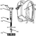
- Fig. 1is a schematic structural diagram of a lower limb weight-assisted exoskeleton robot provided by an embodiment of the present invention
- Fig. 2is an exploded schematic view of the back support device of the robot provided by the embodiment of the present invention
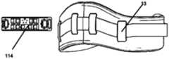
- Fig. 3is an exploded schematic view of the integrated waist pad of the robot provided by the embodiment of the present invention.
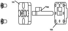
- Fig. 4is an exploded schematic diagram of the size adjustment module of the robot provided by the embodiment of the present invention.
- FIG. 5is a schematic diagram of an exploded hip joint of a robot provided by an embodiment of the present invention.
- FIG. 6is an exploded schematic diagram of a control module of a robot provided by an embodiment of the present invention.
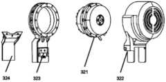
- FIG. 7is a schematic diagram of a hip joint drive module of a robot provided by an embodiment of the present invention.
- Fig. 8is an exploded schematic diagram of the thigh of the robot provided by the embodiment of the present invention.
- Fig. 9is an exploded schematic diagram of the knee joint driving module of the robot provided by the embodiment of the present invention.
- Fig. 10is a schematic diagram of knee joint bending of a robot provided by an embodiment of the present invention.
- Fig. 11is an exploded schematic diagram of the lower leg of the robot provided by the embodiment of the present invention.
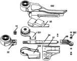
- Fig. 12is an exploded schematic diagram of the ankle joint of the robot provided by the embodiment of the present invention.
- 1-back support device111-outer support rod, 112-inner support rod, 113-first connecting part, 114-hip connector, 115-backpack bracket; 12-integrated shoulder strap; 13-integrated waist pad; 15 -Size adjustment mechanism, 151-upper clip, 152-adjustment rod, 153-lower clip; 2-hip joint, 211-waist rod, 212-waist depth adjustment block, 213-rotation block, 214-second connecting part , 215-load platform; 22-control module, 221-backboard, 222-main control box, 223-battery, 224-aviation plug; 3-thigh, 32-hip drive module, 321-first drive motor , 322-motor frame outer cover, 323-first motor frame, 324-motor inner shell; 33-knee drive module, 331-second motor frame, 332-thigh shell, 333-thigh inner shell, 334-second drive Motor, 335-plug screw, 336-pulley, 337-elastic element,
- the present inventionprovides a hip-knee active-driven lower-limb weight-bearing exoskeleton robot that can be worn on the body of users of different shapes. Effective support and assistance without affecting the knee joint activities.
- the wearable hip-knee active-driven lower limb weight-assisted exoskeleton robotincludes a back support device 1, a hip joint 2, a hip joint drive module 32, two knee joint drive modules 33, two thigh parts 3, Two lower legs 4 , two ankle joints 5 , two plantar devices and a control module 22 .
- the lower end of the back support device 1is connected to the hip joint 2, and the hip joint driving module 32 is drivingly connected to the hip joint 2; the upper end of the thigh 3 is connected to the hip joint driving module 32, and a knee joint medial device 36 is arranged therein;
- the lower end of the part 4is sequentially connected to the ankle joint 5 and the plantar device, and a knee joint lateral device 41 is arranged therein;
- the knee joint medial device 36is connected to the knee joint lateral device 41 to form a knee joint;
- the knee joint driving module 33is arranged on the thigh 3, which can be adjusted to be connected to the lower leg 4;
- the control module 22is respectively connected to the hip joint driving module 32 and the knee joint driving module 33, by controlling the knee joint driving module 33 to adjust the lower leg 4 to realize walking assistance.
- the knee joint driving module 33is internally provided with an elastic component connected to the calf 4, and the motor rotates to drive the elastic component to deform and pull the calf 4, so as to realize active assist when the knee joint is bent or upright.
- the motor in the knee joint driving module 33is not working, the deformation of the elastic component is used to passively assist the knee joint in its reset.
- the back support device 1includes a support module, an integrated back strap 12, an integrated lumbar pad 13 and a hip connector 114; wherein, the support module is arranged in the vertical direction, and its bottom passes through the first
- the connecting part 113is connected to the hip connector 114; the integrated back strap 12 is fixedly connected to the support module, and the integrated waist pad 13 is fixedly connected to the hip connector 114, and the integrated strap 12 and the integrated lumbar pad 13 are arranged on the same side.
- the support moduleincludes an outer support rod 111, an inner support rod 112 inserted in the outer support rod 111, a first size adjustment module and a backpack bracket 115, and the first size adjustment module is fixedly connected to the outer support rod 111 and the inner support rod 111.
- the support rod 112, and the first size adjustment moduleadjusts the length of the support module along the vertical direction by adjusting the fixed position of the outer support rod 111 and the inner support rod 112; 12 is fixedly connected with the support module, and then the human body fixes the robot on the upper body by carrying the integrated back strap 12 and the integrated waist pad 13.
- the first connecting part 113is a connecting piece, the upper end of the connecting piece is hinged to the inner support rod 112 , and the lower end is hinged to the hip connector 114 .
- the hip joint 2is connected to the hip connector 114, including two waist rods 211 symmetrically arranged on the left and right sides of the hip connector 114 , two waist depth adjustment units, two second connection parts 214 and several second size adjustment modules.
- the waist depth adjustment unitincludes a waist depth adjustment block 212 and a rotating block 213, and the waist depth adjustment block 212, one end is inserted in the end of the waist rod 211 away from the hip connector 114, the other end is connected to the rotating block 213 through a cylindrical pin, and the bottom of the rotating block 213 is connected to the hip joint driving module 32 through the second connecting part 214; two waist rods 211 and the waist depth adjustment block 212 are respectively provided with a second size adjustment module, the second size adjustment module is used to adjust the fixed relative position of the waist bar 211 and the waist depth adjustment block 212,
- the application of the second size adjustment module on the hip joint 2helps the robot to be suitable for the waist size of users with different shapes; at the same time, the rotation block 213 is pinned to the waist depth adjustment block 212 through a cylindrical pin, and the rotation block 213 can be wound around the joint Rotation, simulating the rotation of the lower body of the human body from the hip joint 2 position.
- the hip joint 2is also provided with a load platform 215 for load-bearing, and the load platform 215 is arranged on the opposite side of the integrated lumbar pad installation side on the hip connector 114, that is, the back position; the load platform 215 is arranged as A flat plate structure, the control module 22 is detachably mounted on the bottom of the load platform 215 .
- several recovery springsare designed to store the load platform 215 in the embodiment.
- the side of the load platform 215 close to the hip connector 114is provided with a mounting groove that is sunken toward the interior of the plate, and a number of spring mounting positions are arranged in the mounting groove, and the recovery springs are arranged in the spring mounting positions one by one, and the recovery springs are located in the spring mounting positions.
- Compressed statewhen the load platform 215 is not in use, the plate surface is attached to the integrated strap 12 under the action of the recovery spring.
- the hip joint drive module 32includes a motor inner shell 324 , a first motor frame 323 , a motor frame outer cover 322 and a first drive motor 321 , and a motor frame outer cover 322 and a first motor frame 323 sequentially connected from inside to outside. Snap-fit installation forms an installation space for the first drive motor 321 , the first drive motor 321 is installed in the space, and the side of the first drive motor 321 close to the motor inner shell 324 is rotatably connected to the second connecting portion 214 .
- the second connecting part 214is designed as a hip-drive motor connector, and the rotating block 213 of the connector is rotatably connected by a hinge pin, and under the action of the first driving motor 321, the hip-drive motor connector can be driven to rotate around the rotating block 213 Swing back and forth, simulating the back and forth swing of the lower body of the human body from the hip joint 2 position.
- the two thigh parts 3are arranged symmetrically along the left and right directions, and each also includes a thigh shell 332, a thigh inner shell 333, a thigh bar 34, a thigh binding plate 37 and two third size adjustment modules .
- the thigh bar 34is vertically arranged, its upper end is plugged into the first motor frame 323, and its lower end is hinged to the knee joint inner side device 36, and the connection between the thigh bar 34 and the first motor frame 323 is provided with a third size adjustment Module, the third size adjustment module is used to adjust the fixed relative position of the thigh bar 34 and the first motor frame 323, and then adjust the length of the thigh portion 3 along the vertical direction.
- the inner thigh shell 333is fixedly connected to the thigh bar 34, the outer thigh shell 332 is fastened and connected to the inner thigh shell 333, and an installation chamber is formed between the inner thigh shell 333 and the outer thigh shell 332, and the knee joint driving module 33 is arranged in the modified installation chamber indoor.
- the two calf parts 4are arranged symmetrically along the left and right directions, both of which also include a calf slot 42, a calf rod 43, an upper calf shell 46, an upper inner shell 47 of the calf, a lower shell 48 of the calf, a lower inner shell 49 of the calf, and a binding plate for the calf 410 and two fourth size adjustment modules.
- the upper end of the lower leg slot 42is hinged to the knee joint outer device 41.
- the lower leg slot 42forms a certain angle with the knee joint outer device 41, which conforms to the shape of the lower leg of the human body.
- the calf bar 43is plugged into the calf slot 42 from the bottom of the calf slot 42, and a fourth size adjustment module is arranged at the connection between the calf bar 43 and the calf slot 42, and the fourth size adjustment module is used to adjust the calf bar 43
- the relative position fixed with the shank slot 42can further adjust the length of the shank 4 along the vertical direction.
- the calf upper shell 46 and the calf upper inner shell 47are fastened on the outside of the knee joint outer device 41 and connected to the knee joint outer device 41 respectively.
- the lower shell 48 of the lower legis fixedly connected to the lower inner shell 49 of the lower leg bar 43 and the lower leg respectively.
- a closed spaceis formed between the lower inner shells 49 of the shanks, and the closed space is used to install some wires, sensors, etc.; for example, a node plate 45 connected to the shank bar 43 is set in this space, and the wires and IMU sensors, etc., can pass through the node The board 45 is transferred in transit.
- the illustrated robotfixes the thigh 3 and the calf 4 to the human body respectively through the thigh binding plate 37 and the calf binding plate 410; during design, the thigh binding plate 37 is arranged on the side of the thigh bar 34 close to the human body, and the calf is tied to the human body.
- the binding plate 410is arranged on the side of the knee joint outer device 41 and the calf slot 42 close to the human body, and both the thigh binding plate 37 and the calf binding plate 410 are bound to the human body with binding belts.
- the lower end of the knee joint medial device 36 close to the lower leg 4is arranged as an arc-shaped transition structure, and the arc-shaped transition structure is provided with a first through hole along the left and right directions, and the inside of the first through hole
- a deep groove ball bearing 362is provided;
- the upper end of the knee joint outer device 41 away from the calf slot 42is provided with a mounting card slot, which is adapted to the arc transition structure at the lower end of the knee joint medial device 36 arranged on the same side, and
- the two side walls of the installation card slot along the left and right directionsare provided with a second through hole corresponding to the first through hole; the second through hole and the first through hole are connected by a hinge pin; the knee joint simulates the bending of the human knee joint at the hinge and upright.
- a knee joint limiter 44is provided at the bottom of the installation slot of the knee joint outer device 41, and the knee joint limiter 44 is used to limit the knee joint outer device 41 and the knee joint inner device. 36 relative rotation angle.
- the knee joint drive module 33includes a second motor frame 331, a second drive motor 334, a motor drive unit 35, plug screws 335, pulleys 336, elastic elements 337 and ropes 338.
- the second motor frame 331is fixedly connected to the thigh bar 34
- the second drive motor 334is installed on the second motor frame 331
- the motor drive unit 35is driven and connected to the second drive motor 334; in order to reduce the motor drive unit 35
- the motor drive unit 35is fixed on the thigh bar 34 by a fixing plate and located in the installation chamber, and the motor drive unit 35 is connected to the first drive motor 321 and the second drive motor 334 at the same time.
- one end of the plug screw 335is fixedly connected to the output end of the second drive motor 334, and the other end is plugged into the pulley 336, and the plug screw 335 is eccentrically arranged at the output end of the second drive motor 334; the elastic element 337 One end is connected to the pulley 336 , the other end is connected to the rope 338 , and the end of the rope 338 away from the elastic element 337 is connected to the knee joint lateral device 41 .
- the knee joint inner device 36is away from the knee joint outer device 41, and the rope 338 stretches the elastic element 337; when the knee joint is reset, the elastic element 337 drives the rope 338 to quickly return to the upright state , to achieve passive assistance.
- the second drive motor 334When the second drive motor 334 is working, it rotates in one direction to complete a gait cycle assist, and makes the pulley 336 have a highest point and a lowest point on the output surface of the second drive motor 334; the knee joint is from a bent state to an upright state During conversion, the second drive motor 334 unidirectionally rotates to make the pulley 336 move from the lowest point to the highest point; when the knee joint is upright, the pulley 336 is at the highest point, and the rope 338 stretches the elastic element 337 to realize active power assistance; When the bending state changes, the second drive motor 334 rotates in one direction to move the pulley 336 from the highest point to the lowest point; when the knee joint is bent, the pulley 336 is at the lowest point, and the rope 338 relaxes the elastic element 337 to realize active power assistance.
- the second drive motor 334has been rotating in one direction, and the pulley 336 can alternately reach the lowest point and the highest point.
- the rotation direction of the motor 334changes frequently, which can effectively reduce the requirements of the system on the second driving motor 334 .
- the knee joint drive module 33realizes knee joint power assistance through the elastic element 337.
- the control module 22 disclosed in the embodiment of the present applicationis composed of a backplane 221, a main control box 222, a battery 223 and an aviation plug 224;
- the board 121is mounted on the side away from the load platform 215 and the main control box 222 is fastened and installed, and the back plate 121 is connected to the battery 223 on the side away from the load platform 215, and the battery 223 is fastened and installed on the main control box 222 above it;
- the battery 223is used to supply power to the main control box 222 , and the main control box 222 is communicatively connected to the hip joint driving module 32 and the knee joint driving module 33 .
- the ankle joint 5is arranged symmetrically along the left and right directions, and includes a shank connecting rod 511 , a rotating hinge 512 , a foot side support block 513 and a supporting block shell 514 ;
- the upper end of the rod 511is fixedly connected to the calf rod 43, and the lower end is hinged to the rotary hinge 512 along the left-right or front-to-back direction;
- the rotary hinge 512is arranged above the foot-side support block 513, and its lower end is hinged to the foot-side support block 513 along the front-to-back or left-right direction;
- the support block housing 514is covered on the outside of the foot side support block 513 and fixed by threads;
- the calf connecting rod 511has degrees of freedom to rotate relative to the foot side support block 513 along the directions of inward/outward extension and flexion/curvature.
- Plantar pressure measurementis set to plantar pressure measuring piece 515, and plantar pressure measuring piece 515 is connected to foot side support block 513, generally adopts screw thread to fix, and its measuring surface is positioned at the top of plantar device; Plantar pressure measuring piece 515 has Elastic deformation occurs so that the measuring surface fits the degree of freedom on the upper surface of the sole device 52 .
- the two plantar devicesare respectively connected to the ankle joint 5 arranged on the same side thereof, and are used to adjust and fix the human foot, and both include a supporting steel sheet 521, a rubber pad 522 and a fifth size adjustment module; specifically For, the support steel sheet 521 is inserted into the rubber pad 522 along the horizontal direction, and the support steel sheet 521 and the rubber pad 522 together form the sole at the bottom of the foot side support block 513; the support steel sheet 521 is screwed to the foot side support block 513, The measuring surface of the plantar pressure measuring sheet 515 is located above the rubber pad 522; the fifth size adjustment module includes an energy buckle 523 and a nylon toothed belt 524, and the energy buckle 523 is affixed to the rubber pad 522, and if screwed, one end of the nylon toothed belt 524 It is screwed to the foot side support block 513, and the other end goes in and out of the energy buckle 523 to realize the fixation and size adjustment between the sole and the foot side
- the deformation signal of the plantar pressure measuring sheet 515can be converted to obtain the current user's pedaling pressure, which can be used for product testing.
- the first size adjustment module, the second size adjustment module, the third size adjustment module and the fourth size adjustment modulehave the same structure, and all adopt the upper clip 151, the adjustment rod 152 and the lower clip 153 constitute the size adjustment mechanism 15.
- the upper clip 151is fixedly connected to the lower clip 153
- the lower clip 153is used to be detachably connected to a structure that can be adjusted in size
- the adjustment rod 152is clamped and arranged between the upper clip 151 and the lower clip 153 , and its axial ends are respectively connected to the upper clamping piece 151 and the lower clamping piece 153 .
- the adjustment sectionruns through the lower clip 153 and protrudes from the lower clip 153, so that it can be inserted into the preset adjustment hole on the structure that can be adjusted in size .
- the structure that can be adjusted in sizeincludes the connection between the hip joint 2 and the waist bar 211 and the hip connector 114, the connection between the waist bar 211 and the waist depth adjustment block 212, the connection between the first motor frame 323 and the thigh bar 34, The connection between the lower leg slot 42 and the lower leg rod 43 .
- the two parts that need to be adjusted in size at the jointare part one and part two, then part one and part two are provided with a number of adjustment holes.
- the two adjustment holes on part one and part tworealize fibers, and then the lower clip 153 is detachably connected to part one and/or part two.
- the method used in this embodimentis to design a magnet on the lower clip 153, and realize the detachable connection through the magnetic attraction, that is, the lower clip 153 is connected to the outer support rod 111, the hip connector 114, the waist rod 211, and the first motor frame 323. Or the shank slot 42 is magnetically connected; necessarily, the structure connected with the lower clip 153 needs to be magnetic.
- the lower limb weight-assisted exoskeleton robot of the present inventionfully simplifies the driving mechanism at the hip and knee joints, and can be worn on the bodies of users of different shapes to increase wearing comfort; for the knee joint, the driving mechanism is connected to the calf by designing an elastic component
- the part 4provides support and assistance to the lower leg 4, the assistance is reliable and does not affect the free movement of the knee joint, the degree of freedom is higher, the use is more convenient, and the market application prospect is wider.
Landscapes
- Engineering & Computer Science (AREA)
- Robotics (AREA)
- Mechanical Engineering (AREA)
- Rehabilitation Tools (AREA)
- Manipulator (AREA)
Abstract
Description
Translated fromChinese本发明涉及机器人领域,具体涉及一种穿戴式髋膝主动驱动的下肢负重助力外骨骼机器人。The invention relates to the field of robots, in particular to a wearable hip-knee active-driven lower limb load-assisted exoskeleton robot.
外骨骼机器人技术是融合传感、控制、信息、融合、移动计算,为操作者提供一种可穿戴的机械机构的综合技术。外骨骼机器人用于为人体提供助力,在增强人体技能、辅助运动方面有着突出的发展前景,日益成为机器人领域的研究重点。本发明涉及一种可穿戴的下肢负重助力外骨骼,当人体负重行走时提供支持和助力,类似结构在US13139933专利里也有所提及。Exoskeleton robot technology is a comprehensive technology that integrates sensing, control, information, fusion, and mobile computing to provide operators with a wearable mechanical mechanism. Exoskeleton robots are used to provide assistance to the human body, and have outstanding development prospects in enhancing human skills and assisting movement, and have increasingly become the focus of research in the field of robotics. The present invention relates to a wearable lower extremity load-bearing exoskeleton, which provides support and assistance when the human body is walking with a load. Similar structures are also mentioned in the US13139933 patent.
当人体处于背负重物状态,尤其是在背负重物长时间行走时,其身体肌肉和骨骼容易疲劳和损伤。长期处于这样的状态下容易引肌肉骨骼疾病。When the human body is in a state of carrying heavy objects, especially when walking for a long time with heavy objects on its back, its body muscles and bones are prone to fatigue and damage. Being in this state for a long time can easily lead to musculoskeletal diseases.
US15349602专利描述了一种用于支撑人体的无动力负重外骨骼结构,该结构由仿生脊柱、腰部、腿部和足部组成,无外部驱动或弹储能装置。仿生脊柱通过机械结构与绑缚与人体的固定,仿生脊柱背负重物,腰部用于连接仿生脊柱和腿部,腿部结构通过绑缚固定在大腿上,当身体背负重物时,有外骨骼承担负载重量,减轻重物对人体造成的伤害。然而该外骨骼并未安装驱动结构,故无法在行走中提供有效的助力及支撑。The US15349602 patent describes a non-powered load-bearing exoskeleton structure for supporting the human body, which consists of a bionic spine, waist, legs and feet, without external drive or elastic energy storage devices. The bionic spine is fixed to the human body through mechanical structure and binding. The bionic spine carries heavy loads. The waist is used to connect the bionic spine and legs. The leg structure is fixed on the thigh through binding. When the body is carrying heavy objects, there is an exoskeleton Bear the weight of the load and reduce the damage caused by heavy objects to the human body. However, the exoskeleton is not equipped with a drive structure, so it cannot provide effective assistance and support during walking.
US15339293和US13639984专利中也描述了类似的结构,但两者同样无法在行走中提供有效的助力及支撑。Similar structures are also described in US15339293 and US13639984 patents, but both cannot provide effective power assistance and support during walking.
US14634403专利公开了一种用于支撑身体重量并辅助人体行走的外骨骼结构,其通过安放在背部的电机带动钢绳来驱动三铰链结构的膝关节,实现膝关节、髋关节的屈伸和屈曲运动。但因膝关节结构较为主被动混合式,无法在背负重物时提供有效助力。US14634403 patent discloses an exoskeleton structure for supporting body weight and assisting human walking. It uses a motor placed on the back to drive a steel cable to drive a knee joint with a three-hinge structure to achieve flexion, extension and flexion of the knee joint and hip joint. . However, because the knee joint structure is relatively active and passive, it cannot provide effective assistance when carrying heavy loads.
US15604891专利公开了一种用于支撑身体重量并辅助人体行走的外骨骼结构,其中膝关有多个片状结构铰链组成,并由电机驱动,同样的该膝关节结构较为复杂,在背负重物时膝关节容易出现铰链无法闭合情况,无法提供有效助力。US15604891 patent discloses an exoskeleton structure for supporting body weight and assisting human walking. The knee joint is composed of multiple sheet-like structure hinges and is driven by a motor. At this time, the knee joint is prone to hinge failure and cannot provide effective assistance.
CN201811252375.1公开了一种膝关节主动助力的负重外骨骼,通过背部驱动电机驱动绳索,在人体膝关节伸时提供主动助力,为人体提供额外的扭矩,辅助人体行走。但该外骨骼无法将有效将重量传递至地面。CN201811252375.1 discloses a load-bearing exoskeleton that actively assists the knee joint. The motor drives the rope through the back to provide active assist when the human knee joint is extended, providing additional torque for the human body and assisting the human body to walk. But the exoskeleton cannot effectively transfer weight to the ground.
CN201920639613.8公开了一种髋关节、膝关节助力外骨骼,通过电机驱动滚珠丝结构实现髋关节、膝关节助力,辅助人体行走。同时该外骨骼会影响膝关节自由运动,容易使人体失去平衡。CN201920639613.8 discloses a hip and knee power-assisted exoskeleton, which drives the ball wire structure through a motor to realize power-assisted hip and knee joints and assists human walking. At the same time, the exoskeleton will affect the free movement of the knee joint, which will easily make the human body lose its balance.
发明内容Contents of the invention
本发明目的在于提供一种穿戴式髋膝主动驱动的下肢负重助力外骨骼机器人,以精简轻便的结构,可贴合地穿戴于不同体形用户的身体上,增加穿戴舒适性,提供可靠的支撑和助力,并能够在提供有效的支撑及助力等情况下不影响膝关节。The purpose of the present invention is to provide a wearable hip-knee active-driven lower limb load-assisted exoskeleton robot, which can be worn on the bodies of users of different shapes with a simplified and lightweight structure, so as to increase wearing comfort and provide reliable support and Assist, and can provide effective support and assistance without affecting the knee joint.
为达成上述目的,本发明提出如下技术方案:一种穿戴式髋膝主动驱动的下肢负重助力外骨骼机器人,包括背部支撑装置、髋关节、髋关节驱动模块、两个膝关节驱动模块、两个大腿部、两个小腿部、两个踝关节、两个足底装置和控制模块:In order to achieve the above purpose, the present invention proposes the following technical solution: a wearable hip-knee active-driven lower limb load-assisted exoskeleton robot, including a back support device, a hip joint, a hip joint driving module, two knee joint driving modules, two Upper Leg, Two Lower Legs, Two Ankles, Two Foot Units and Control Module:
所述背部支撑装置下端连接于髋关节,所述髋关节驱动模块驱动连接于髋关节;所述大腿部上端连接于髋关节驱动模块,其内设置有膝关节内侧装置;所述小腿部下端依次连接于踝关节和足底装置,其内设置有膝关节外侧装置;所述膝关节内侧装置连接于膝关节外侧装置构成膝关节;所述膝关节驱动模块设置在大腿部上,可调节连接于小腿部;The lower end of the back supporting device is connected to the hip joint, and the driving module of the hip joint is connected to the hip joint; the upper end of the thigh is connected to the driving module of the hip joint, and a knee joint medial device is arranged therein; the lower leg The lower end is connected to the ankle joint and the plantar device in turn, and the knee joint outer device is arranged in it; the knee joint inner device is connected to the knee joint outer device to form a knee joint; the knee joint driving module is arranged on the thigh, which can The adjustment is connected to the lower leg;
所述控制模块分别连接于髋关节驱动模块和膝关节驱动模块,通过控制膝关节驱动模块调节小腿部,实现行走助力。The control module is respectively connected to the hip joint driving module and the knee joint driving module, and the lower leg is adjusted by controlling the knee joint driving module to realize walking assistance.
进一步的,所述背部支撑装置包括支撑模块、一体式背带、一体化腰垫和髋连接件;所述支撑模块沿竖直方向布置,其底部经第一连接部连接于髋连接件;所述一体式背带固连于支撑模块,所述一体化腰垫固连于髋连接件,并且一体式背带和一体化腰垫同侧布置;Further, the back support device includes a support module, an integrated strap, an integrated lumbar pad, and a hip connector; the support module is arranged in a vertical direction, and its bottom is connected to the hip connector through a first connecting part; the The integrated back strap is fixedly connected to the support module, the integrated lumbar pad is fixedly connected to the hip connector, and the integrated back strap and the integrated lumbar pad are arranged on the same side;
所述支撑模块包括内支撑杆、外支撑杆、第一尺寸调节模块和背包支架;所述内支撑杆插设于外支撑杆中,所述第一尺寸调节模块固连外支撑杆和内支撑杆,并且第一尺寸调节模块通过调节外支撑杆和内支撑杆的固定位置调节支撑模块沿竖直方向的长度;所述背包支架对应固连于所述一体式背带。The support module includes an inner support rod, an outer support rod, a first size adjustment module and a backpack support; the inner support rod is inserted into the outer support rod, and the first size adjustment module is fixedly connected to the outer support rod and the inner support rod, and the first size adjustment module adjusts the length of the support module along the vertical direction by adjusting the fixed positions of the outer support rod and the inner support rod; the backpack bracket is correspondingly connected to the integrated strap.
进一步的,定义人体的前后左右方向为所述下肢负重助力外骨骼机器人的前后左右方向;Further, the front, back, left, and right directions of the human body are defined as the front, rear, left, and right directions of the lower limb weight-assisted exoskeleton robot;
所述髋关节连接于髋连接件,包括对称设置在髋连接件左右侧的两根腰杆、两个腰深调节单元、两个第二连接部和若干第二尺寸调节模块;The hip joint is connected to the hip joint, including two lumbar bars symmetrically arranged on the left and right sides of the hip joint, two waist depth adjustment units, two second connection parts and several second size adjustment modules;
所述腰杆靠近髋连接件的端部插设于髋连接件,所述髋连接件与两根腰杆连接处分别设置有一第二尺寸调节模块,该第二尺寸调节模块用于调节腰杆与髋连接件固定的相对位置,进而调节腰杆与髋连接件围成的腰部宽度;The end of the lumbar bar close to the hip link is inserted into the hip link, and a second size adjustment module is respectively provided at the connection between the hip link and the two lumbar bars, and the second size adjustment module is used to adjust the waist bar The fixed relative position with the hip joint, and then adjust the width of the waist surrounded by the lumbar bar and the hip joint;
所述腰深调节单元包括腰深调节块和旋转块;所述腰深调节块一端插设于腰杆远离髋连接件的端部,另一端经圆柱销连接于所述旋转块;所述旋转块底部经第二连接部连接于髋关节驱动模块;所述两根腰杆上与腰深调节块的连接处分别设置有一第二尺寸调节模块,该第二尺寸调节模块用于调节腰杆与腰深调节块固定的相对位置,进而调节腰杆与腰深调节块围成的腰部深度。The waist depth adjustment unit includes a waist depth adjustment block and a rotating block; one end of the waist depth adjustment block is inserted into the end of the waist bar away from the hip connector, and the other end is connected to the rotating block through a straight pin; the rotating The bottom of the block is connected to the hip joint drive module through the second connection part; the connection between the two waist bars and the waist depth adjustment block is respectively provided with a second size adjustment module, and the second size adjustment module is used to adjust the waist bar and the waist depth adjustment block. The fixed relative position of the waist depth adjustment block can further adjust the waist depth surrounded by the waist bar and the waist depth adjustment block.
进一步的,所述髋关节驱动模块包括自内向外依次连接的电机内壳、第一电机架和电机架外罩,以及连接设置在所述第一电机架和电机架外罩之间的第一驱动电机,所述第一驱动电机靠近电机内壳的一侧转动连接于第二连接部。Further, the hip joint drive module includes a motor inner shell, a first motor frame, and a motor frame outer cover sequentially connected from inside to outside, and a first drive motor connected between the first motor frame and the motor frame outer cover , the side of the first driving motor close to the motor inner shell is rotatably connected to the second connecting portion.
进一步的,所述两个大腿部沿左右方向对称设置,均还包括大腿外壳、大腿内壳、大腿杆、大腿绑缚板和两个第三尺寸调节模块;所述大腿杆竖向设置,其上端插接于第一电机架、下端铰接于膝关节内侧装置,并且大腿杆与第一电机架的连接处设置有一第三尺寸调节模块,该第三尺寸调节模块用于调节大腿杆与第一电机架固定的相对位置,进而调节大腿部沿竖直方向的长度;所述大腿绑缚板设置在大腿杆靠近人体侧,用于与人体的大腿部绑缚连接;Further, the two thigh parts are arranged symmetrically along the left and right directions, and each also includes a thigh shell, a thigh inner shell, a thigh rod, a thigh binding plate and two third size adjustment modules; the thigh rod is vertically arranged, Its upper end is inserted into the first motor frame, and its lower end is hinged to the knee joint inner device, and a third size adjustment module is provided at the connection between the thigh bar and the first motor frame, and the third size adjustment module is used to adjust the thigh bar and the first motor frame. The relative position of a motor frame is fixed, and then the length of the thigh along the vertical direction is adjusted; the thigh binding plate is arranged on the side of the thigh bar close to the human body, and is used for binding and connecting with the thigh of the human body;
所述大腿内壳固接于大腿杆,大腿外壳扣合连接于大腿内壳,并且大腿内壳与大腿外壳之间形成一安装腔室;所述膝关节驱动模块设置在所述安装腔室内;The inner thigh shell is fixedly connected to the thigh bar, the outer thigh shell is buckled and connected to the inner thigh shell, and an installation chamber is formed between the inner thigh shell and the outer thigh shell; the knee joint drive module is arranged in the installation chamber;
所述两个小腿部沿左右方向对称设置,均还包括小腿插槽、小腿杆、小腿上外壳、小腿上内壳、小腿下外壳、小腿下内壳、小腿绑缚板和两个第四尺寸调节模块;所述小腿插槽上端铰接于膝关节外侧装置,所述小腿杆自小腿插槽底端插接于小腿插槽,并且小腿杆与小腿插槽的连接处设置有一第四尺寸调节模块,该第四尺寸调节模块用于调节小腿杆与小腿插槽固定的相对位置,进而调节小腿部沿竖直方向的长度;所述小腿绑缚板设置在膝关节外侧装置及小腿插槽靠近人体侧,用于与人体的小腿部绑缚连接;The two shanks are arranged symmetrically along the left and right directions, and each also includes a shank slot, a shank rod, an upper shell of the shank, an upper inner shell of the shank, a lower shell of the shank, a lower inner shell of the shank, a shank binding plate and two fourth Size adjustment module; the upper end of the shank slot is hinged to the outside device of the knee joint, the shank bar is inserted into the shank slot from the bottom end of the shank slot, and a fourth size adjustment module is provided at the joint between the shank bar and the shank slot. module, the fourth size adjustment module is used to adjust the fixed relative position of the calf bar and the calf slot, and then adjust the length of the calf along the vertical direction; the calf binding plate is arranged on the outside device of the knee joint and the calf slot Near the side of the human body, it is used to bind and connect with the lower leg of the human body;
所述小腿上外壳、小腿上内壳扣合设置在所述膝关节外侧装置外侧,并分别连接于所述膝关节外侧装置;所述小腿下外壳分别固连于小腿杆和小腿下内壳,并且小腿下外壳与小腿下内壳连接后罩设在所述小腿杆外侧。The upper shell of the calf and the upper inner shell of the calf are fastened and arranged on the outside of the knee joint outer device, and are respectively connected to the outer knee device; the lower leg shell is fixedly connected to the calf bar and the lower inner shell of the calf respectively, And the lower shell of the lower leg is connected with the lower inner shell of the lower leg, and the rear cover is arranged on the outside of the lower leg rod.
进一步的,所述膝关节内侧装置靠近小腿部的下端设置为弧形过渡结构,所述弧形过渡结构沿左右方向设置有第一贯通孔,并且第一贯通孔内设置有深沟球轴承;所述膝关节外侧装置远离小腿插槽的上端设置有安装卡槽,所述安装卡槽适配于同侧设置的膝关节内侧装置下端的弧形过渡结构,并且安装卡槽沿左右方向的两侧壁设置有位置对应于第一贯通孔的第二贯通孔;所述第二贯通孔和第一贯通孔经铰接销连接;Further, the lower end of the knee joint medial device close to the calf is set as an arc-shaped transition structure, and the arc-shaped transition structure is provided with a first through hole along the left and right direction, and a deep groove ball bearing is arranged in the first through hole ; The upper end of the outer knee joint device away from the lower leg slot is provided with a card slot for installation, and the card slot is adapted to the arc transition structure at the lower end of the medial knee device provided on the same side, and the card slot is along the left and right direction The two side walls are provided with a second through hole corresponding to the first through hole; the second through hole is connected to the first through hole through a hinge pin;
所述安装卡槽底部设置有一膝关节限位块,所述膝关节限位块用于限制膝关节外侧装置和膝关节内侧装置的相对转动角度。A knee joint limiting block is provided at the bottom of the installation card slot, and the knee joint limiting block is used to limit the relative rotation angle of the knee joint outer device and the knee joint inner device.
进一步的,所述膝关节驱动模块包含第二电机架、第二驱动电机、电机驱动单元、塞打螺丝、滑轮、弹性元件和绳索;Further, the knee joint drive module includes a second motor frame, a second drive motor, a motor drive unit, plug screws, pulleys, elastic elements and ropes;
所述第二电机架固连于大腿杆,所述第二驱动电机安装在第二电机架上,所述电机驱动单元驱动连接于第二驱动电机;所述塞打螺丝一端固连于所述第二驱动电机的输出端、另一端插接于滑轮,塞打螺丝在所述第二驱动电机的输出端偏心设置;所述弹性元件一端连接于滑轮、另一端连接于绳索,并且绳索远离弹性元件的端部连接于膝关节外侧装置;The second motor frame is fixedly connected to the thigh bar, the second driving motor is installed on the second motor frame, and the motor driving unit is drivingly connected to the second driving motor; one end of the plug screw is fixedly connected to the The output end and the other end of the second drive motor are plugged into the pulley, and the plug screw is eccentrically arranged at the output end of the second drive motor; one end of the elastic element is connected to the pulley, and the other end is connected to the rope, and the rope is away from the elastic The end of the element is connected to the knee lateral device;
当第二驱动电机不工作,所述膝关节弯曲时,膝关节内侧装置远离膝关节外侧装置,绳索拉伸弹性元件;所述膝关节复位时,弹性元件带动绳索实现被动助力;When the second drive motor is not working and the knee joint is bent, the inner device of the knee joint is away from the outer device of the knee joint, and the rope stretches the elastic element; when the knee joint is reset, the elastic element drives the rope to realize passive power assistance;
当第二驱动电机工作,其单方向旋转一周完成一个步态周期的助力,并且使得所述滑轮在第二驱动电机的输出面存在一最高点及最低点;所述膝关节由弯曲状态向直立状态变换时,第二驱动电机单向旋转使得滑轮由最低点向最高点移动;所述膝关节直立时,滑轮位于最高点,绳索拉伸弹性元件实现主动助力;所述膝关节由直立状态向弯曲状态变换时,第二驱动电机单向旋转使得滑轮由最高点向最低点移动;所述膝关节弯曲时,滑轮位于最低点,绳索放松弹性元件实现主动助力。When the second drive motor works, it rotates in one direction to complete a gait cycle assist, and makes the pulley have a highest point and a lowest point on the output surface of the second drive motor; the knee joint is from a bent state to an upright position When the state changes, the second drive motor rotates in one direction so that the pulley moves from the lowest point to the highest point; when the knee joint is upright, the pulley is at the highest point, and the rope stretches the elastic element to realize active power assistance; the knee joint moves from the upright state to the highest point. When the bending state changes, the second drive motor rotates in one direction to move the pulley from the highest point to the lowest point; when the knee joint is bent, the pulley is at the lowest point, and the elastic element is loosened by the rope to realize active power assistance.
进一步的,所述踝关节沿左右方向对称设置,包括小腿连接杆、旋转铰链、足侧支撑块和支撑块外壳,以及用于测量足底压力的足底压力测量装置;Further, the ankle joint is arranged symmetrically along the left and right directions, including a calf connecting rod, a rotary hinge, a foot side support block and a support block shell, and a plantar pressure measuring device for measuring plantar pressure;
所述小腿连接杆沿竖直方向设置,小腿连接杆上端固接于小腿杆、下端沿左右或前后方向铰接于旋转铰链;所述旋转铰链设置在足侧支撑块的上方,其下端沿前后或左右方向与足侧支撑块铰接;所述支撑块外壳罩设在足侧支撑块外侧;所述小腿连接杆具有相对足侧支撑块沿内/外展和屈伸/曲方向旋转的自由度;The shank connecting rod is arranged in the vertical direction, the upper end of the shank connecting rod is fixedly connected to the shank rod, and the lower end is hinged to the rotary hinge along the left and right or front and rear directions; The left and right directions are hinged with the foot-side support block; the support block outer shell is arranged on the outside of the foot-side support block; the calf connecting rod has degrees of freedom to rotate relative to the foot-side support block along the inward/outward extension and flexion/extension/bending directions;
所述足底压力测量装置设置为足底压力测量片,足底压力测量片固连于足侧支撑块,其测量面位于足底装置的上方;所述足底压力测量片具有发生弹性形变使其测量面贴合于足底装置上表面的自由度。The plantar pressure measuring device is set as a plantar pressure measuring piece, which is fixedly connected to the foot side support block, and its measuring surface is located above the plantar device; the plantar pressure measuring piece has elastic deformation to make it It measures the degree of freedom with which the surface fits on the upper surface of the plantar device.
进一步的,所述两个足底装置分别对应连接于与其同侧设置的踝关节,用于调节固定人体足部,均包括支撑钢片、橡胶垫和第五尺寸调节模块;Further, the two plantar devices are respectively connected to the ankle joints on the same side thereof, and are used to adjust and fix the human foot, and each includes a supporting steel sheet, a rubber pad and a fifth size adjustment module;
所述支撑钢片沿水平方向插入橡胶垫中,支撑钢片与橡胶垫共同构成位于足侧支撑块底部的鞋底;所述支撑钢片固连于足侧支撑块,所述足底压力测量片的测量面位于橡胶垫上方;所述第五尺寸调节模块包括能量扣和尼龙齿带,所述能量扣固接于橡胶垫,所述尼龙齿带一端固接于足侧支撑块,另一端出入能量扣,实现对鞋底和足侧支撑块松紧调节。The supporting steel sheet is inserted into the rubber pad along the horizontal direction, and the supporting steel sheet and the rubber pad together form the sole at the bottom of the foot-side support block; the support steel sheet is fixedly connected to the foot-side support block, and the plantar pressure measuring sheet The measuring surface is located above the rubber pad; the fifth size adjustment module includes an energy buckle and a nylon toothed belt, the energy buckle is fixed to the rubber pad, one end of the nylon toothed belt is fixed to the foot side support block, and the other end goes in and out The energy buckle can adjust the tightness of the sole and the side support block.
进一步的,所述第一尺寸调节模块、第二尺寸调节模块、第三尺寸调节模块和第四尺寸调节模块结构相同,均包括上夹片、调节杆和下夹片;Further, the first size adjustment module, the second size adjustment module, the third size adjustment module and the fourth size adjustment module have the same structure, and all include an upper clip, an adjustment rod and a lower clip;
所述上夹片固连于下夹片,下夹片用于可拆卸连接于可进行尺寸调节的结构;所述调节杆夹持设置于上夹片与下夹片之间,其轴向两端分别连接于上夹片和下夹片;The upper clamp is fixedly connected to the lower clamp, and the lower clamp is used for detachable connection to a structure that can be adjusted in size; the adjustment rod is clamped and arranged between the upper clamp and the lower clamp, and its axial two The ends are respectively connected to the upper clip and the lower clip;
定义调节杆连接于下夹片的端部为调节端,则所述调节段贯穿下夹片且凸出于下夹片,以便插设于可进行尺寸调节的结构上预设的调节孔。The end of the adjustment rod connected to the lower clamp is defined as the adjustment end, and the adjustment section passes through the lower clamp and protrudes from the lower clamp, so as to be inserted into the preset adjustment hole on the structure that can be adjusted in size.
由以上技术方案可知,本发明的技术方案获得了如下有益效果:As can be seen from the above technical solutions, the technical solution of the present invention has obtained the following beneficial effects:
本发明公开的穿戴式髋膝主动驱动的下肢负重助力外骨骼机器人,包括背部支撑装置、连接于背部支撑装置下端的髋关节、连接于髋关节的髋关节驱动模块、两个上端连接于髋关节驱动模块的大腿部、两个小腿部、在小腿部下端依次连接的两个踝关节和两个足底装置、两个设置在大腿部上、可调节连接于小腿部的膝关节驱动模块,以及连接于髋关节驱动模块和膝关节驱动模块的控制模块,其中,大腿部设置有膝关节内侧装置,小腿部设置有膝关节外侧装置,膝关节内侧装置连接于膝关节外侧装置构成膝关节;控制模块通过控制膝关节驱动模块调节小腿部,能够在提供有效的支撑及助力等情况下不影响膝关节活动,实现行走助力。The wearable hip-knee actively driven lower limb weight-assisted exoskeleton robot disclosed by the present invention includes a back support device, a hip joint connected to the lower end of the back support device, a hip joint drive module connected to the hip joint, and two upper ends connected to the hip joint The thigh part of the driving module, two calf parts, two ankle joints and two plantar devices successively connected at the lower end of the calf part, two knees arranged on the thigh part and adjustablely connected to the calf part A joint driving module, and a control module connected to the hip joint driving module and the knee joint driving module, wherein the thigh is provided with a knee joint inner device, the lower leg is provided with a knee joint outer device, and the knee joint inner device is connected to the knee joint The outer device constitutes the knee joint; the control module adjusts the lower leg by controlling the knee joint drive module, which can provide effective support and assistance without affecting the knee joint activities and realize walking assistance.
本发明的膝关节驱动模块设置第二驱动电机、连接于第该电机输出端的塞打螺丝、设置在塞打螺丝上的滑轮、连接于滑轮的弹性元件和用于连接弹性元件和小腿部的绳索,通过弹性元件的形变实现第二驱动电机在工作状态下的主动助力、在不工作状态下的被动助力,当机器人与人体步态不一致时,人体膝关节仍可正常活动,不会因失去平衡造成危险。同时,膝关节驱动模块中第二 驱动电机只需单向旋转完成步态周期的助力,无需电机往复旋转,避免电机重复启动造成的耗损。The knee joint driving module of the present invention is provided with a second drive motor, a plug screw connected to the output end of the motor, a pulley arranged on the plug screw, an elastic element connected to the pulley, and a pin for connecting the elastic element and the lower leg The rope, through the deformation of the elastic element, realizes the active assist of the second drive motor in the working state and the passive assist in the non-working state. When the gait of the robot is inconsistent with that of the human body, the human knee joint can still move normally without loss of Balance creates danger. At the same time, the second drive motor in the knee joint drive module only needs to rotate in one direction to complete the power assist of the gait cycle, without the need for the motor to rotate back and forth, avoiding the loss caused by the repeated start of the motor.
应当理解,前述构思以及在下面更加详细地描述的额外构思的所有组合只要在这样的构思不相互矛盾的情况下都可以被视为本公开的发明主题的一部分。It should be understood that all combinations of the foregoing concepts, as well as additional concepts described in more detail below, may be considered part of the inventive subject matter of the present disclosure, provided such concepts are not mutually inconsistent.
结合附图从下面的描述中可以更加全面地理解本发明教导的前述和其他方面、实施例和特征。本发明的其他附加方面例如示例性实施方式的特征和/或有益效果将在下面的描述中显见,或通过根据本发明教导的具体实施方式的实践中得知。The foregoing and other aspects, embodiments and features of the present teachings can be more fully understood from the following description when taken in conjunction with the accompanying drawings. Other additional aspects of the invention, such as the features and/or advantages of the exemplary embodiments, will be apparent from the description below, or learned by practice of specific embodiments in accordance with the teachings of the invention.
附图不意在按比例绘制。在附图中,在各个图中示出的每个相同或近似相同的组成部分可以用相同的标号表示。为了清晰起见,在每个图中,并非每个组成部分均被标记。现在,将通过例子并参考附图来描述本发明的各个方面的实施例,其中:The figures are not intended to be drawn to scale. In the drawings, each identical or nearly identical component that is illustrated in various figures may be represented by a like reference numeral. For purposes of clarity, not every component may be labeled in every drawing. Embodiments of the various aspects of the invention will now be described by way of example with reference to the accompanying drawings, in which:
图1为本发明实施例提供的下肢负重助力外骨骼机器人的结构示意图;Fig. 1 is a schematic structural diagram of a lower limb weight-assisted exoskeleton robot provided by an embodiment of the present invention;
图2为本发明实施例提供的机器人的背部支撑装置分解示意图;Fig. 2 is an exploded schematic view of the back support device of the robot provided by the embodiment of the present invention;
图3为本发明实施例提供的机器人的一体式腰垫分解示意图;Fig. 3 is an exploded schematic view of the integrated waist pad of the robot provided by the embodiment of the present invention;
图4为本发明实施例提供的机器人的尺寸调节模块分解示意图;Fig. 4 is an exploded schematic diagram of the size adjustment module of the robot provided by the embodiment of the present invention;
图5为本发明实施例提供的机器人的髋关节分解示意图;5 is a schematic diagram of an exploded hip joint of a robot provided by an embodiment of the present invention;
图6为本发明实施例提供的机器人的控制模块分解示意图;6 is an exploded schematic diagram of a control module of a robot provided by an embodiment of the present invention;
图7为本发明实施例提供的机器人的髋关节驱动模块示意图;7 is a schematic diagram of a hip joint drive module of a robot provided by an embodiment of the present invention;
图8为本发明实施例提供的机器人的大腿部分解示意图;Fig. 8 is an exploded schematic diagram of the thigh of the robot provided by the embodiment of the present invention;
图9为本发明实施例提供的机器人的膝关节驱动模块分解示意图;Fig. 9 is an exploded schematic diagram of the knee joint driving module of the robot provided by the embodiment of the present invention;
图10为本发明实施例提供的机器人的膝关节弯曲示意图;Fig. 10 is a schematic diagram of knee joint bending of a robot provided by an embodiment of the present invention;
图11为本发明实施例提供的机器人的小腿部分解示意图;Fig. 11 is an exploded schematic diagram of the lower leg of the robot provided by the embodiment of the present invention;
图12为本发明实施例提供的机器人的踝关节分解示意图。Fig. 12 is an exploded schematic diagram of the ankle joint of the robot provided by the embodiment of the present invention.
图中,各标记的具体意义为:In the figure, the specific meaning of each mark is:
1-背部支撑装置,111-外支撑杆,112-内支撑杆,113-第一连接部,114-髋连接件,115-背包支架;12-一体化背带;13-一体化腰垫;15-尺寸调节机构,151-上夹片,152-调节杆,153-下夹片;2-髋关节,211-腰杆,212-腰深调节块,213-旋转块,214-第二连接部,215-负载平台;22-控制模块,221-背板,222-主控盒, 223-电池,224-航空插头;3-大腿部,32-髋关节驱动模块,321-第一驱动电机,322-电机架外罩,323-第一电机架,324-电机内壳;33-膝关节驱动模块,331-第二电机架,332-大腿外壳,333-大腿内壳,334-第二驱动电机,335-塞打螺丝,336-滑轮,337-弹性元件,338-绳索;34-大腿杆,35-电机驱动单元,36-膝关节内侧装置,362-深沟球轴承,37-大腿绑缚板;4-小腿部,41-膝关节外侧装置,42-小腿插槽,43-小腿杆,44-膝关节限位块,45-节点板,46-小腿上外壳,47-小腿上内壳,48-小腿下外壳,49-小腿下内壳,410-小腿绑缚板;5-踝关节,511-小腿连接杆,512-旋转铰链,513-足侧支撑块,514-支撑块外壳,515-足底压力测量片;52-鞋底,521-支撑钢片,522-橡胶垫,523-能量扣,524-尼龙齿带。1-back support device, 111-outer support rod, 112-inner support rod, 113-first connecting part, 114-hip connector, 115-backpack bracket; 12-integrated shoulder strap; 13-integrated waist pad; 15 -Size adjustment mechanism, 151-upper clip, 152-adjustment rod, 153-lower clip; 2-hip joint, 211-waist rod, 212-waist depth adjustment block, 213-rotation block, 214-second connecting part , 215-load platform; 22-control module, 221-backboard, 222-main control box, 223-battery, 224-aviation plug; 3-thigh, 32-hip drive module, 321-first drive motor , 322-motor frame outer cover, 323-first motor frame, 324-motor inner shell; 33-knee drive module, 331-second motor frame, 332-thigh shell, 333-thigh inner shell, 334-second drive Motor, 335-plug screw, 336-pulley, 337-elastic element, 338-rope; 34-thigh rod, 35-motor drive unit, 36-knee joint medial device, 362-deep groove ball bearing, 37-thigh tie Binding plate; 4-calf, 41-outer knee device, 42-calf slot, 43-calf rod, 44-knee limit block, 45-gusset plate, 46-calf upper shell, 47-calf upper Inner shell, 48-calf lower shell, 49-calf lower inner shell, 410-calf binding plate; 5-ankle joint, 511-calf connecting rod, 512-rotary hinge, 513-foot support block, 514-support block Shell, 515-plantar pressure measuring piece; 52-sole, 521-support steel sheet, 522-rubber pad, 523-energy buckle, 524-nylon toothed belt.
为使本发明实施例的目的、技术方案和优点更加清楚,下面将结合本发明实施例的附图,对本发明实施例的技术方案进行清楚、完整地描述。显然,所描述的实施例是本发明的一部分实施例,而不是全部的实施例。基于所描述的本发明的实施例,本领域普通技术人员在无需创造性劳动的前提下所获得的所有其他实施例,都属于本发明保护的范围。除非另作定义,此处使用的技术术语或者科学术语应当为本发明所属领域内具有一般技能的人士所理解的通常意义。In order to make the purpose, technical solutions and advantages of the embodiments of the present invention clearer, the technical solutions of the embodiments of the present invention will be clearly and completely described below in conjunction with the drawings of the embodiments of the present invention. Apparently, the described embodiments are some, not all, embodiments of the present invention. Based on the described embodiments of the present invention, all other embodiments obtained by persons of ordinary skill in the art without creative work shall fall within the protection scope of the present invention. Unless otherwise defined, the technical terms or scientific terms used herein shall have the usual meanings understood by those skilled in the art to which the present invention belongs.
本发明专利申请说明书以及权利要求书中使用的“第一”、“第二”以及类似的词语并不表示任何顺序、数量或者重要性,而只是用来区分不同的组成部分。同样,除非上下文清楚地指明其它情况,否则单数形式的“一个”“一”或者“该”等类似词语也不表示数量限制,而是表示存在至少一个。“包括”或者“包含”等类似的词语意指出现在“包括”或者“包含”前面的元件或者物件涵盖出现在“包括”或者“包含”后面列举的特征、整体、步骤、操作、元素和/或组件,并不排除一个或多个其它特征、整体、步骤、操作、元素、组件和/或其集合的存在或添加。“上”“下”“左”“右”等仅用于表示相对位置关系,当被描述对象的绝对位置改变后,则该相对位置关系也可能相应地改变。"First", "second" and similar words used in the specification and claims of the patent application of the present invention do not indicate any order, quantity or importance, but are only used to distinguish different components. Likewise, unless the context clearly dictates otherwise, words such as "a", "an" or "the" in the singular do not imply a limitation of number, but rather indicate that there is at least one. "comprises" or "comprises" and similar words mean that the elements or items presented before "comprises" or "comprises" include the features, integers, steps, operations, elements and/or items listed after "comprises" or "comprises" or component, does not preclude the existence or addition of one or more other features, integers, steps, operations, elements, components and/or collections thereof. "Up", "Down", "Left" and "Right" are only used to indicate relative positional relationship. When the absolute position of the described object changes, the relative positional relationship may also change accordingly.
基于现有技术公开的外骨骼助力结构,由于膝关节的结构设计不同需要配置不同的驱动结构,因此常出现外骨骼工作时无法提供有效助力的情况;并且,常用驱动机构由电机带动,而为实现驱动机构带动膝关节贴合人体的往复屈伸,电机需要经常重启往复旋转,进而造成电机迅速耗损。为了克服现有技术的不足,本发明提供一种可贴合地穿戴于不同体形用户身体上的髋膝主动驱动的下肢负重助力外骨骼机器人,通过弹性元件和滑轮配合实现弹性助力,不仅能够提供有效的支撑及助力,且不影响膝关节活动。Based on the exoskeleton power-assisted structure disclosed in the prior art, because the structural design of the knee joint requires different driving structures, it often occurs that the exoskeleton cannot provide effective power assistance during work; To realize the reciprocating flexion and extension of the knee joint that is driven by the drive mechanism to fit the human body, the motor needs to be restarted and reciprocated to rotate frequently, resulting in rapid wear and tear of the motor. In order to overcome the deficiencies of the prior art, the present invention provides a hip-knee active-driven lower-limb weight-bearing exoskeleton robot that can be worn on the body of users of different shapes. Effective support and assistance without affecting the knee joint activities.
下面结合附图所示的具体实施例,对本发明公开的穿戴式髋膝主动驱动的下肢负重助力外骨骼机器人作进一步具体介绍。In the following, the wearable hip-knee actively driven lower limb weight-assisted exoskeleton robot disclosed in the present invention will be further specifically introduced in combination with the specific embodiments shown in the accompanying drawings.
结合图1所示,穿戴式髋膝主动驱动的下肢负重助力外骨骼机器人包括背部支撑装置1、髋关节2、髋关节驱动模块32、两个膝关节驱动模块33、两个大腿部3、两个小腿部4、两个踝关节5、两个足底装置和控制模块22。安装时,背部支撑装置1下端连接髋关节2,髋关节驱动模块32驱动连接于髋关节2;大腿部3上端连接于髋关节驱动模块32,其内设置有膝关节内侧装置36;小腿部4下端依次连接于踝关节5和足底装置,其内设置有膝关节外侧装置41;膝关节内侧装置36连接于膝关节外侧装置41构成膝关节;膝关节驱动模块33设置在大腿部3上,可调节连接于小腿部4;控制模块22分别连接于髋关节驱动模块32和膝关节驱动模块33,通过控制膝关节驱动模块33调节小腿部4,实现行走助力。As shown in Figure 1, the wearable hip-knee active-driven lower limb weight-assisted exoskeleton robot includes a
具体实施时,膝关节驱动模块33内部设置连接于小腿部4的弹性组件,通过电机转动带动弹性组件形变牵引小腿部4,在膝关节弯曲或直立时实现主动助力。同时,当膝关节驱动模块33中的电机不工作时,通过弹性组件的形变在膝关节复位时被动助力。During specific implementation, the knee
结合图2和图3所示,所述背部支撑装置1包括支撑模块、一体式背带12、一体化腰垫13和髋连接件114;其中,支撑模块沿竖直方向布置,其底部经第一连接部113连接于髋连接件114;一体式背带12固连于支撑模块,一体化腰垫13固连于髋连接件114,并且一体式背带12和一体化腰垫13同侧布置。本实施例中,支撑模块包括外支撑杆111、插设于外支撑杆111中的内支撑杆112、第一尺寸调节模块和背包支架115,第一尺寸调节模块固连外支撑杆111和内支撑杆112,并且第一尺寸调节模块通过调节外支撑杆111和内支撑杆112的固定位置调节支撑模块沿竖直方向的长度;背包支架115对应固连于一体式背带12,将一体式背带12与支撑模块固连,进而人体通过背负一体式背带12和一体式腰垫13将机器人固定在上半身。附图中,第一连接部113为连接片,连接片上端铰接于内支撑杆112、下端铰接于髋连接件114。As shown in FIG. 2 and FIG. 3 , the
结合图5所示,定义人体的前后左右方向为下肢负重助力外骨骼机器人的前后左右方向;髋关节2连接于髋连接件114,包括对称设置在髋连接件114左右侧的两根腰杆211、两个腰深调节单元、两个第二连接部214和若干第二尺寸调节模块。安装时,腰杆211靠近髋连接件114的端部插设于髋连接件114,髋连接件114与两根腰杆211连接处分别设置有一第二尺寸调节模块,该第二尺 寸调节模块用于调节腰杆211与髋连接件114固定的相对位置,进而调节腰杆211与髋连接件114围成的腰部宽度;腰深调节单元包括腰深调节块212和旋转块213,腰深调节块212一端插设于腰杆211远离髋连接件114的端部,另一端经圆柱销连接于旋转块213,旋转块213底部经第二连接部214连接于髋关节驱动模块32;两根腰杆211上与腰深调节块212的连接处分别设置有一第二尺寸调节模块,该第二尺寸调节模块用于调节腰杆211与腰深调节块212固定的相对位置,进而调节腰杆211与腰深调节块212围成的腰部深度。As shown in FIG. 5 , define the front, rear, left, and right directions of the human body as the front, rear, left, and right directions of the lower limb weight-assisted exoskeleton robot; the
第二尺寸调节模块在髋关节2上的应用,助益于本机器人适用于不同形体用户的腰部尺寸;同时旋转块213通过圆柱销与腰深调节块212销接,旋转块213可绕连接处转动,模拟人体下半身自髋关节2位置的转动。The application of the second size adjustment module on the
图示的实施例中,髋关节2还设置有用于负重的负载平台215,该负载平台215设置在髋连接件114上一体式腰垫安装侧的相对侧,即背部位置;负载平台215设置为一平板结构,控制模块22可拆卸安装在负载平台215的底部。为减小负载平台215在不使用时的占用空间,实施例设计了若干回收弹簧收纳负载平台215。具体的,负载平台215靠近髋连接件114的侧边设置有一向平板内部凹陷的安装槽,安装槽内设置有若干弹簧安装位,回收弹簧一一对应设置在弹簧安装位内,并且回收弹簧处于压缩状态;负载平台215不使用时在回收弹簧的作用下板面贴合于一体式背带12。In the illustrated embodiment, the
结合图7所示,髋关节驱动模块32包括自内向外依次连接的电机内壳324、第一电机架323、电机架外罩322和第一驱动电机321,电机架外罩322和第一电机架323扣合安装,其间形成第一驱动电机321安装空间,第一驱动电机321安装在该空间内,并且第一驱动电机321靠近电机内壳324的一侧转动连接于第二连接部214。实施例中,第二连接部214即设计为髋驱动电机连接件,该连接件旋转块213通过铰接销转动连接,在第一驱动电机321的作用下可带动髋驱动电机连接件绕旋转块213前后摆动,模拟人体下半身自髋关节2位置的前后摆动。As shown in FIG. 7 , the hip
结合图8和图11所示,两个大腿部3沿左右方向对称设置,均还包括大腿外壳332、大腿内壳333、大腿杆34、大腿绑缚板37和两个第三尺寸调节模块。如图示,大腿杆34竖向设置,其上端插接于第一电机架323、下端铰接于膝关节内侧装置36,并且大腿杆34与第一电机架323的连接处设置有一第三尺寸调节模块,该第三尺寸调节模块用于调节大腿杆34与第一电机架323固定的相对位置,进而调节大腿部3沿竖直方向的长度。As shown in Fig. 8 and Fig. 11, the two
大腿内壳333固接于大腿杆34,大腿外壳332扣合连接于大腿内壳333,并且大腿内壳333与大腿外壳332之间形成一安装腔室,膝关节驱动模块33设置在改安装腔室内。The
两个小腿部4沿左右方向对称设置,均还包括小腿插槽42、小腿杆43、小腿上外壳46、小腿上内壳47、小腿下外壳48、小腿下内壳49、小腿绑缚板410和两个第四尺寸调节模块。安装时,小腿插槽42上端铰接于膝关节外侧装置41,实施例中,小腿插槽42与膝关节外侧装置41成一定夹角,贴合人体小腿外形。小腿杆43自小腿插槽42底端插接于小腿插槽42,并且小腿杆43与小腿插槽42的连接处设置有一第四尺寸调节模块,该第四尺寸调节模块用于调节小腿杆43与小腿插槽42固定的相对位置,进而调节小腿部4沿竖直方向的长度。The two
另外,为避免灰尘等进入膝关节,影响膝关节的正常转动,将小腿上外壳46、小腿上内壳47扣合设置在膝关节外侧装置41外侧,并分别连接于膝关节外侧装置41。同时,安装时将小腿下外壳48分别固连于小腿杆43和小腿下内壳49,小腿下外壳48与小腿下内壳49连接后罩设在小腿杆43外侧,进而在小腿下外壳48与小腿下内壳49之间形成一闭合空间,该闭合空间用于安装部分导线、传感器等;例如在该空间内设置一连接于小腿杆43的节点板45,导线和IMU传感器等可通过该节点板45进行中转传送。In addition, in order to prevent dust and the like from entering the knee joint and affecting the normal rotation of the knee joint, the calf
图示的机器人通过大腿绑缚板37和小腿绑缚板410将大腿部3、小腿部4分别与人体固定;设计时,大腿绑缚板37设置在大腿杆34靠近人体侧,小腿绑缚板410设置在膝关节外侧装置41及小腿插槽42靠近人体侧,并且大腿绑缚板37和小腿绑缚板410均采用绑缚带与人体绑缚。The illustrated robot fixes the
进一步结合图8和图9所示,膝关节内侧装置36靠近小腿部4的下端设置为弧形过渡结构,该弧形过渡结构沿左右方向设置有第一贯通孔,并且第一贯通孔内设置有深沟球轴承362;膝关节外侧装置41远离小腿插槽42的上端设置有安装卡槽,该安装卡槽适配于同侧设置的膝关节内侧装置36下端的弧形过渡结构,并且安装卡槽沿左右方向的两侧壁设置有位置对应于第一贯通孔的第二贯通孔;第二贯通孔和第一贯通孔经铰接销连接;膝关节在铰接处模拟人体膝关节的弯曲和直立。Further combined with Fig. 8 and Fig. 9, the lower end of the knee joint
为避免膝关节发生超过人体极限的弯曲,膝关节外侧装置41的安装卡槽底部设置有一膝关节限位块44,该膝关节限位块44用于限制膝关节外侧装置41和膝关节内侧装置36的相对转动角度。In order to prevent the knee joint from bending beyond the limit of the human body, a knee joint limiter 44 is provided at the bottom of the installation slot of the knee joint
结合图9和图10所示,膝关节驱动模块33包含第二电机架331、第二驱动 电机334、电机驱动单元35、塞打螺丝335、滑轮336、弹性元件337和绳索338。组装时,第二电机架331固连于大腿杆34,第二驱动电机334安装在第二电机架331上,并且电机驱动单元35驱动连接于第二驱动电机334;为减小电机驱动单元35安装时占用的空间,电机驱动单元35采用一固定板固定在大腿杆34上、位于安装腔室内,并且电机驱动单元35同时连接于第一驱动电机321和第二驱动电机334。9 and 10, the knee
如图9所示,塞打螺丝335一端固连于第二驱动电机334的输出端、另一端插接于滑轮336,塞打螺丝335在第二驱动电机334的输出端偏心设置;弹性元件337一端连接于滑轮336、另一端连接于绳索338,并且绳索338远离弹性元件337的端部连接于膝关节外侧装置41。As shown in Figure 9, one end of the
膝关节组装并连接好膝关节驱动模块33后,工作过程如下:After the knee joint is assembled and connected to the knee
当第二驱动电机334不工作,膝关节弯曲时,膝关节内侧装置36远离膝关节外侧装置41,绳索338拉伸弹性元件337;膝关节复位时,弹性元件337带动绳索338快速恢复至直立状态,实现被动助力。当第二驱动电机334工作,其单方向旋转一周完成一个步态周期的助力,并且使得滑轮336在第二驱动电机334的输出面存在一最高点及最低点;膝关节由弯曲状态向直立状态变换时,第二驱动电机334单向旋转使得滑轮336由最低点向最高点移动;膝关节直立时,滑轮336位于最高点,绳索338拉伸弹性元件337实现主动助力;膝关节由直立状态向弯曲状态变换时,第二驱动电机334单向旋转使得滑轮336由最高点向最低点移动;膝关节弯曲时,滑轮336位于最低点,绳索338放松弹性元件337实现主动助力。When the
在膝关节驱动模块33实现的一整个步态周期内第二驱动电机334一直单向旋转,滑轮336便可交替到达最低点和最高点,与现有技术的其他驱动方案不同,无需第二驱动电机334频繁变换旋转方向,可有效降低系统对第二驱动电机334的要求。膝关节驱动模块33通过弹性元件337实现膝关节助力,当驱动与人体步态不一致时,人体膝关节仍可正常活动,不会因失去平衡造成危险。During the entire gait cycle realized by the knee
结合图6所示,本申请实施例公开的控制模块22由背板221、主控盒222、电池223和航空插头224组成;具体结构为:背板221与负载平台215板面螺栓固定,背板121远离负载平台215侧的上方和主控盒222扣合安装,背板121远离负载平台215侧的下方连接电池223,电池223与其上方的主控盒222扣合安装;航空插头224电连接于电池223,用于向主控盒222供电,主控盒222通信连接于髋关节驱动模块32和膝关节驱动模块33。As shown in Figure 6, the
结合图12所示,踝关节5沿左右方向对称设置,包括小腿连接杆511、旋转铰链512、足侧支撑块513和支撑块外壳514;其中,小腿连接杆511沿竖直方向设置,小腿连接杆511上端固接于小腿杆43、下端沿左右或前后方向铰接于旋转铰链512;旋转铰链512设置在足侧支撑块513的上方,其下端沿前后或左右方向与足侧支撑块513铰接;支撑块外壳514罩设在足侧支撑块513外侧,并采用螺纹固定;小腿连接杆511具有相对足侧支撑块513沿内/外展和屈伸/曲方向旋转的自由度。足底压力测量设置为足底压力测量片515,足底压力测量片515固连于足侧支撑块513,一般采用螺纹固定,其测量面位于足底装置的上方;足底压力测量片515具有发生弹性形变使其测量面贴合于足底装置52上表面的自由度。As shown in FIG. 12 , the
如图12所示,两个足底装置分别对应连接于与其同侧设置的踝关节5,用于调节固定人体足部,均包括支撑钢片521、橡胶垫522和第五尺寸调节模块;具体为,支撑钢片521沿水平方向插入橡胶垫522中,支撑钢片521与橡胶垫522共同构成位于足侧支撑块513底部的鞋底;支撑钢片521采用螺纹固接于足侧支撑块513,足底压力测量片515的测量面位于橡胶垫522上方;第五尺寸调节模块包括能量扣523和尼龙齿带524,能量扣523固接于橡胶垫522,如采用螺纹固定,尼龙齿带524一端采用螺纹固接于足侧支撑块513,另一端出入能量扣523,实现对鞋底和足侧支撑块513之间的固定和尺寸调节。当足底压力测量片515受到上方人体脚部向下踩踏的压力发生形变,贴合于橡胶垫522表面,足底压力测量片515的形变信号经过转换即能获得当前用户踩踏的压力,可以用于产品测试。As shown in Figure 12, the two plantar devices are respectively connected to the ankle joint 5 arranged on the same side thereof, and are used to adjust and fix the human foot, and both include a supporting
结合附图所示的实施例,第一尺寸调节模块、第二尺寸调节模块、第三尺寸调节模块和第四尺寸调节模块结构相同,均采用由上夹片151、调节杆152和下夹片153构成的尺寸调节机构15。具体的,上夹片151固连于下夹片153,下夹片153用于可拆卸连接于可进行尺寸调节的结构;调节杆152夹持设置于上夹片151与下夹片153之间,其轴向两端分别连接于上夹片151和下夹片153。In conjunction with the embodiment shown in the drawings, the first size adjustment module, the second size adjustment module, the third size adjustment module and the fourth size adjustment module have the same structure, and all adopt the
定义调节杆152连接于下夹片153的端部为调节端,则调节段贯穿下夹片153且凸出于下夹片153,以便插设于可进行尺寸调节的结构上预设的调节孔。Define the end of the
实施例中,可进行尺寸调节的结构包括髋关节2要腰杆211与髋连接件114连接处、腰杆211与腰深调节块212连接处、第一电机架323与大腿杆34连接处、小腿插槽42与小腿杆43连接处。假设需要进行连接处尺寸调节的两个零件为零件一和零件二,则零件一和零件二上均设置有若干调节孔,连接时,将 调节杆152的调节段插设于选定长度对应的零件一和零件二上的两个调节孔实现纤维,再将下夹片153与零件一和/或零件二可拆卸连接。本实施例采用的方式是,在下夹片153上设计磁石,通过磁吸作用实现可拆卸连接,即下夹片153与外支撑杆111、髋连接件114、腰杆211、第一电机架323或小腿插槽42磁吸连接;必然的,与下夹片153连接的结构需要具有磁性。In the embodiment, the structure that can be adjusted in size includes the connection between the
本发明的下肢负重助力外骨骼机器人充分精简髋、膝关节处的驱动机构,贴合地穿戴于不同体形用户的身体上,增加穿戴舒适性;对于膝关节,驱动机构通过设计弹性组件连接小腿部4对小腿部4提供支撑和助力,助力可靠并且不影响膝关节的自由活动,自由度更高,使用更方便,市场应用前景更广泛。The lower limb weight-assisted exoskeleton robot of the present invention fully simplifies the driving mechanism at the hip and knee joints, and can be worn on the bodies of users of different shapes to increase wearing comfort; for the knee joint, the driving mechanism is connected to the calf by designing an elastic component The
虽然本发明已以较佳实施例揭露如上,然其并非用以限定本发明。本发明所属技术领域中具有通常知识者,在不脱离本发明的精神和范围内,当可作各种的更动与润饰。因此,本发明的保护范围当视权利要求书所界定者为准。Although the present invention has been disclosed above with preferred embodiments, it is not intended to limit the present invention. Those skilled in the art of the present invention may make various changes and modifications without departing from the spirit and scope of the present invention. Therefore, the scope of protection of the present invention should be defined by the claims.
Claims (10)
Translated fromChinesePriority Applications (1)
| Application Number | Priority Date | Filing Date | Title |
|---|---|---|---|
| PCT/CN2021/140098WO2023115334A1 (en) | 2021-12-21 | 2021-12-21 | Wearable lower limb weight-bearing power-assisted exoskeleton robot with hip and knee active drive |
Applications Claiming Priority (1)
| Application Number | Priority Date | Filing Date | Title |
|---|---|---|---|
| PCT/CN2021/140098WO2023115334A1 (en) | 2021-12-21 | 2021-12-21 | Wearable lower limb weight-bearing power-assisted exoskeleton robot with hip and knee active drive |
Publications (1)
| Publication Number | Publication Date |
|---|---|
| WO2023115334A1true WO2023115334A1 (en) | 2023-06-29 |
Family
ID=86900912
Family Applications (1)
| Application Number | Title | Priority Date | Filing Date |
|---|---|---|---|
| PCT/CN2021/140098CeasedWO2023115334A1 (en) | 2021-12-21 | 2021-12-21 | Wearable lower limb weight-bearing power-assisted exoskeleton robot with hip and knee active drive |
Country Status (1)
| Country | Link |
|---|---|
| WO (1) | WO2023115334A1 (en) |
Cited By (8)
| Publication number | Priority date | Publication date | Assignee | Title |
|---|---|---|---|---|
| CN117462371A (en)* | 2023-12-28 | 2024-01-30 | 中国科学院自动化研究所 | A two-degree-of-freedom motion-assisted knee joint exoskeleton robot |
| CN117919061A (en)* | 2024-03-25 | 2024-04-26 | 中国科学院长春光学精密机械与物理研究所 | Lower limb exoskeleton based on active rigidity-variable joint |
| CN118044926A (en)* | 2024-03-29 | 2024-05-17 | 北京精博现代假肢矫形器技术有限公司 | Modular artificial limb movable part structure linkage device |
| CN118717483A (en)* | 2024-06-14 | 2024-10-01 | 中国科学院深圳先进技术研究院 | Lower limb powered exoskeleton device for rehabilitation assistance |
| CN119347731A (en)* | 2024-12-24 | 2025-01-24 | 杭州智元研究院有限公司 | Active lower limb four-link heterogeneous exoskeleton and use method thereof |
| CN119454412A (en)* | 2024-12-26 | 2025-02-18 | 中国人民解放军陆军军医大学第一附属医院 | A wearable walking aid with gait analysis function |
| CN119795135A (en)* | 2024-12-30 | 2025-04-11 | 上海理工大学 | Active-passive hybrid drive flexible lower limb exoskeleton system and coordinated control method |
| CN120131389A (en)* | 2025-05-14 | 2025-06-13 | 浙江大学 | A high-degree-of-freedom multi-directional exoskeleton power-assisting device |
Citations (5)
| Publication number | Priority date | Publication date | Assignee | Title |
|---|---|---|---|---|
| CN103054692A (en)* | 2013-01-29 | 2013-04-24 | 苏州大学 | Wearable lower limb exoskeleton walking-assisted robot |
| US20190001493A1 (en)* | 2017-06-30 | 2019-01-03 | Hyundai Motor Company | Multi-bar linkage, lower-limb exoskeleton robot using the same, and method of controlling the same |
| CN109730904A (en)* | 2019-02-19 | 2019-05-10 | 刘坤 | A wearable rest exoskeleton |
| CN112936228A (en)* | 2021-02-08 | 2021-06-11 | 延边大学 | Lower limb exoskeleton robot |
| CN112999018A (en)* | 2021-03-29 | 2021-06-22 | 迈宝智能科技(苏州)有限公司 | Active-passive switching wearable lower limb load exoskeleton |
- 2021
- 2021-12-21WOPCT/CN2021/140098patent/WO2023115334A1/ennot_activeCeased
Patent Citations (5)
| Publication number | Priority date | Publication date | Assignee | Title |
|---|---|---|---|---|
| CN103054692A (en)* | 2013-01-29 | 2013-04-24 | 苏州大学 | Wearable lower limb exoskeleton walking-assisted robot |
| US20190001493A1 (en)* | 2017-06-30 | 2019-01-03 | Hyundai Motor Company | Multi-bar linkage, lower-limb exoskeleton robot using the same, and method of controlling the same |
| CN109730904A (en)* | 2019-02-19 | 2019-05-10 | 刘坤 | A wearable rest exoskeleton |
| CN112936228A (en)* | 2021-02-08 | 2021-06-11 | 延边大学 | Lower limb exoskeleton robot |
| CN112999018A (en)* | 2021-03-29 | 2021-06-22 | 迈宝智能科技(苏州)有限公司 | Active-passive switching wearable lower limb load exoskeleton |
Cited By (10)
| Publication number | Priority date | Publication date | Assignee | Title |
|---|---|---|---|---|
| CN117462371A (en)* | 2023-12-28 | 2024-01-30 | 中国科学院自动化研究所 | A two-degree-of-freedom motion-assisted knee joint exoskeleton robot |
| CN117462371B (en)* | 2023-12-28 | 2024-04-05 | 中国科学院自动化研究所 | A two-degree-of-freedom motion-assisted knee exoskeleton robot |
| CN117919061A (en)* | 2024-03-25 | 2024-04-26 | 中国科学院长春光学精密机械与物理研究所 | Lower limb exoskeleton based on active rigidity-variable joint |
| CN117919061B (en)* | 2024-03-25 | 2024-05-31 | 中国科学院长春光学精密机械与物理研究所 | Lower limb exoskeleton based on active rigidity-variable joint |
| CN118044926A (en)* | 2024-03-29 | 2024-05-17 | 北京精博现代假肢矫形器技术有限公司 | Modular artificial limb movable part structure linkage device |
| CN118717483A (en)* | 2024-06-14 | 2024-10-01 | 中国科学院深圳先进技术研究院 | Lower limb powered exoskeleton device for rehabilitation assistance |
| CN119347731A (en)* | 2024-12-24 | 2025-01-24 | 杭州智元研究院有限公司 | Active lower limb four-link heterogeneous exoskeleton and use method thereof |
| CN119454412A (en)* | 2024-12-26 | 2025-02-18 | 中国人民解放军陆军军医大学第一附属医院 | A wearable walking aid with gait analysis function |
| CN119795135A (en)* | 2024-12-30 | 2025-04-11 | 上海理工大学 | Active-passive hybrid drive flexible lower limb exoskeleton system and coordinated control method |
| CN120131389A (en)* | 2025-05-14 | 2025-06-13 | 浙江大学 | A high-degree-of-freedom multi-directional exoskeleton power-assisting device |
Similar Documents
| Publication | Publication Date | Title |
|---|---|---|
| WO2023115334A1 (en) | Wearable lower limb weight-bearing power-assisted exoskeleton robot with hip and knee active drive | |
| CN112999018B (en) | Active-passive switching wearable lower limb load exoskeleton | |
| CN109223456B (en) | Lower limb exoskeleton robot system based on man-machine terminal interaction | |
| EP3954351B1 (en) | Ankle-assisted exoskeleton device | |
| CN109662869B (en) | Wearable flexible lower limb power-assisted robot | |
| CN114260879B (en) | Wearable hip-knee active-driven lower limb load assisting exoskeleton robot | |
| CN103610568B (en) | Human-simulated external skeleton robot assisting lower limbs | |
| CN106901947B (en) | Wearable lower limb exoskeleton assisted walking robot mechanism | |
| CN108095976B (en) | Bionic knee joint rehabilitation training device with passive rebound function | |
| CN105686927B (en) | Collapsible mobile lower limb exoskeleton | |
| CN109623782B (en) | Wearable power-assisted exoskeleton robot | |
| CN109044742B (en) | Rehabilitation type lower limb exoskeleton | |
| CN112972211A (en) | Lower limb exoskeleton device | |
| CN203436523U (en) | Ten-freedom-degree lower limb walking-assisting device | |
| CN206837089U (en) | A kind of flexible wearable lower limb assistance exoskeleton clothes | |
| CN107174490A (en) | A kind of portable device for healing and training | |
| CN112192549A (en) | Enhanced lower limb exoskeleton robot system | |
| CN108161909A (en) | A kind of bionical lower limb exoskeleton robot carried for auxiliary | |
| CN115302489A (en) | Instantaneous center adjustable variable-rigidity flexible knee joint exoskeleton | |
| CN216731801U (en) | Active and passive combination of wearable lower limb assist exoskeleton device | |
| CN215689599U (en) | Lower extremity exoskeleton device | |
| CN205459236U (en) | Collapsible portable low limbs ectoskeleton | |
| CN112515921B (en) | A flexible lower limb rehabilitation robot for assisting stroke patients to restore gait | |
| WO2022204843A1 (en) | Active and passive switchable wearable lower limb load-bearing exoskeleton | |
| CN207915460U (en) | A kind of bionical lower limb exoskeleton robot for assisting carrying |
Legal Events
| Date | Code | Title | Description |
|---|---|---|---|
| 121 | Ep: the epo has been informed by wipo that ep was designated in this application | Ref document number:21968487 Country of ref document:EP Kind code of ref document:A1 | |
| NENP | Non-entry into the national phase | Ref country code:DE | |
| 122 | Ep: pct application non-entry in european phase | Ref document number:21968487 Country of ref document:EP Kind code of ref document:A1 |