WO2023112539A1 - Robot device and robot system - Google Patents
Robot device and robot systemDownload PDFInfo
- Publication number
- WO2023112539A1 WO2023112539A1PCT/JP2022/041127JP2022041127WWO2023112539A1WO 2023112539 A1WO2023112539 A1WO 2023112539A1JP 2022041127 WJP2022041127 WJP 2022041127WWO 2023112539 A1WO2023112539 A1WO 2023112539A1
- Authority
- WO
- WIPO (PCT)
- Prior art keywords
- robot
- joint
- surgical tool
- link
- force
- Prior art date
- Legal status (The legal status is an assumption and is not a legal conclusion. Google has not performed a legal analysis and makes no representation as to the accuracy of the status listed.)
- Ceased
Links
Images


Classifications
- A—HUMAN NECESSITIES
- A61—MEDICAL OR VETERINARY SCIENCE; HYGIENE
- A61B—DIAGNOSIS; SURGERY; IDENTIFICATION
- A61B34/00—Computer-aided surgery; Manipulators or robots specially adapted for use in surgery
- A61B34/30—Surgical robots
- A61B34/37—Leader-follower robots
- A—HUMAN NECESSITIES
- A61—MEDICAL OR VETERINARY SCIENCE; HYGIENE
- A61B—DIAGNOSIS; SURGERY; IDENTIFICATION
- A61B34/00—Computer-aided surgery; Manipulators or robots specially adapted for use in surgery
- A61B34/20—Surgical navigation systems; Devices for tracking or guiding surgical instruments, e.g. for frameless stereotaxis
- A—HUMAN NECESSITIES
- A61—MEDICAL OR VETERINARY SCIENCE; HYGIENE
- A61B—DIAGNOSIS; SURGERY; IDENTIFICATION
- A61B34/00—Computer-aided surgery; Manipulators or robots specially adapted for use in surgery
- A61B34/30—Surgical robots
- A—HUMAN NECESSITIES
- A61—MEDICAL OR VETERINARY SCIENCE; HYGIENE
- A61B—DIAGNOSIS; SURGERY; IDENTIFICATION
- A61B34/00—Computer-aided surgery; Manipulators or robots specially adapted for use in surgery
- A61B34/30—Surgical robots
- A61B34/35—Surgical robots for telesurgery
- A—HUMAN NECESSITIES
- A61—MEDICAL OR VETERINARY SCIENCE; HYGIENE
- A61B—DIAGNOSIS; SURGERY; IDENTIFICATION
- A61B90/00—Instruments, implements or accessories specially adapted for surgery or diagnosis and not covered by any of the groups A61B1/00 - A61B50/00, e.g. for luxation treatment or for protecting wound edges
- A61B90/90—Identification means for patients or instruments, e.g. tags
- B—PERFORMING OPERATIONS; TRANSPORTING
- B25—HAND TOOLS; PORTABLE POWER-DRIVEN TOOLS; MANIPULATORS
- B25J—MANIPULATORS; CHAMBERS PROVIDED WITH MANIPULATION DEVICES
- B25J19/00—Accessories fitted to manipulators, e.g. for monitoring, for viewing; Safety devices combined with or specially adapted for use in connection with manipulators
- B—PERFORMING OPERATIONS; TRANSPORTING
- B25—HAND TOOLS; PORTABLE POWER-DRIVEN TOOLS; MANIPULATORS
- B25J—MANIPULATORS; CHAMBERS PROVIDED WITH MANIPULATION DEVICES
- B25J3/00—Manipulators of leader-follower type, i.e. both controlling unit and controlled unit perform corresponding spatial movements
- B—PERFORMING OPERATIONS; TRANSPORTING
- B25—HAND TOOLS; PORTABLE POWER-DRIVEN TOOLS; MANIPULATORS
- B25J—MANIPULATORS; CHAMBERS PROVIDED WITH MANIPULATION DEVICES
- B25J9/00—Programme-controlled manipulators
- B25J9/10—Programme-controlled manipulators characterised by positioning means for manipulator elements
- A—HUMAN NECESSITIES
- A61—MEDICAL OR VETERINARY SCIENCE; HYGIENE
- A61B—DIAGNOSIS; SURGERY; IDENTIFICATION
- A61B34/00—Computer-aided surgery; Manipulators or robots specially adapted for use in surgery
- A61B34/30—Surgical robots
- A61B2034/302—Surgical robots specifically adapted for manipulations within body cavities, e.g. within abdominal or thoracic cavities
- A—HUMAN NECESSITIES
- A61—MEDICAL OR VETERINARY SCIENCE; HYGIENE
- A61F—FILTERS IMPLANTABLE INTO BLOOD VESSELS; PROSTHESES; DEVICES PROVIDING PATENCY TO, OR PREVENTING COLLAPSING OF, TUBULAR STRUCTURES OF THE BODY, e.g. STENTS; ORTHOPAEDIC, NURSING OR CONTRACEPTIVE DEVICES; FOMENTATION; TREATMENT OR PROTECTION OF EYES OR EARS; BANDAGES, DRESSINGS OR ABSORBENT PADS; FIRST-AID KITS
- A61F9/00—Methods or devices for treatment of the eyes; Devices for putting in contact-lenses; Devices to correct squinting; Apparatus to guide the blind; Protective devices for the eyes, carried on the body or in the hand
- A61F9/007—Methods or devices for eye surgery
Definitions
- the present disclosurerelates to a robot device and a robot system.
- Patent Literature 1discloses a device connected to a micropositioning arm and to which a surgical tool is connected.
- One aspect of the present disclosureprovides a robotic device and a robotic arm system capable of facilitating alignment of surgical tools.
- a robotic deviceincludes a first robot including a base and a distal end, and a surgical instrument supported by the distal end of the first robot and inserted into a patient's body. and a second robot supporting the first robot, the first robot being configured to be manipulated by a user by applying force directly to the first robot.
- a robotic systemincludes a robotic device and a support device, wherein the robotic device includes a first robot including a base and a distal end, and a distal end of the first robot. and a second robot supported by and supporting a surgical instrument to be inserted into the patient's body, the first robot being operable by a user to directly apply force to the first robot.
- the assisting deviceassists the user in manipulating the first robot for aligning the insertion point of the surgical tool and the remote motion center of the surgical tool.
- FIG. 1is a diagram showing an example of a schematic configuration of a robot system 1 according to an embodiment
- FIG. FIG. 2is a diagram showing an example of placement of the robot apparatus 2 with respect to a patient
- FIG. 2is a diagram showing an example of a schematic configuration of a robot R1
- FIG. 4is a diagram schematically showing an example of transmission of braking force by a transmission 7
- FIG. 10is a diagram showing an example of detecting a positional deviation between an insertion point I of a surgical instrument T and a remote motion center RCM;
- FIG. 10is a diagram showing an example of detecting a positional deviation between an insertion point I of a surgical instrument T and a remote motion center RCM; 4 is a diagram showing an example of marking on the surgical instrument T; FIG. 10 is a flow chart showing an example of alignment between an insertion point I of a surgical instrument T and a remote motion center RCM using a marker M.
- FIG.It is a figure which shows typically the example of a schematic structure of the support arm apparatus 20 which concerns on embodiment. It is a figure which shows typically the example of a schematic structure of the support arm apparatus 20 which concerns on embodiment. It is a figure which shows typically the example of a schematic structure of 22 A of connection mechanisms which concern on a modification.
- connection mechanism 22Bwhich concerns on a modification. It is a figure which shows typically the example of a schematic structure of 22 C of connection mechanisms based on a modification. It is a figure which shows the example of schematic structure of the parallel link mechanism 21 and connection mechanism 22 which concern on a modification. It is a figure which shows the example of schematic structure of the parallel link mechanism 21 and connection mechanism 22 which concern on a modification. 4 is a diagram showing an example of assembly of the parallel link mechanism 21 and the connection mechanism 22; FIG. It is a figure which shows the example of schematic structure of the assembled parallel link mechanism 21 and the connection mechanism 22.
- FIG. 3is a diagram showing an example of a schematic configuration of a robot R1 and a robot R2; 1 is a diagram showing an example of a schematic configuration of a robot device 2; FIG. 1 is a diagram showing an example of a schematic configuration of a robot device 2; FIG. It is a schematic diagram which shows the example of a schematic structure of a retraction
- FIG. 22is a diagram for explaining forces applied to each part in the configuration shown in FIG. 21; 4A and 4B are diagrams for explaining the principle of operation of the retraction mechanism 101; FIG. 4A and 4B are diagrams for explaining the principle of operation of the retraction mechanism 101; FIG. 4A and 4B are diagrams for explaining the principle of operation of the retraction mechanism 101; FIG. 4A and 4B are diagrams for explaining the principle of operation of the retraction mechanism 101; FIG.
- FIG. 4A and 4Bare diagrams for explaining the principle of operation of the retraction mechanism 101;
- FIG. 4A and 4Bare diagrams for explaining the principle of operation of the retraction mechanism 101;
- FIG. 10is a diagram for explaining an example of operation during active saving;
- FIG. 10is a diagram for explaining an example of operation during active saving;
- FIG. 11is a diagram for explaining an example of operation during passive evacuation;
- FIG. 11is a diagram for explaining an example of operation during passive evacuation;
- an industrial robotis configured as a system in which a force sensor is attached to the robot arm and moves passively when a human touches it. be.
- the risk of the robot going out of control due to the failure of the force sensor and the increase in the size of the arm structureare obstacles, and it cannot be used in medical treatment as it is.
- a usersuch as a doctor can directly apply force to the robot to operate it.
- the robotcan be moved to an arbitrary position, pose, etc., or can be made stationary. Positioning of the surgical tool by direct teaching, for example, positioning of the insertion point of the surgical tool and the center of remote movement can be easily performed.
- FIG. 1is a diagram showing an example of a schematic configuration of a robot system 1 according to an embodiment.
- the robot system 1is used for surgery.
- a case where the surgery is ophthalmic surgerywill be described as an example.
- the patient's eye to be operated onis referred to as eye E and is illustrated.
- An operator(physician or the like) is referred to as a user U and illustrated.
- FIG. 1schematically shows a portion of the user's U hand.
- the robot system 1includes a robot device 2, a microscope MC, a monitor 3, a robot R3, and a support device 8.
- the microscope MCobserves the operative field.
- the field of view of the microscope MCcan include the eyeball E, the surgical tool T inside the eyeball E, and the like.
- the monitor 3displays an observation image (operative field image) of the microscope MC.
- the user Uobserves the operative field by looking at the observation image of the microscope MC displayed on the monitor 3 or looking directly at the eyepiece of the microscope MC.
- Surgeryproceeds through operations using visual feedback of the relative positional relationship between the surgical tool T reflected in the surgical field and the robot device 2 at hand.
- the robot device 2is a robot placed near the patient (patient-side robot) and includes two robots connected in series.
- the first robotis shown as robot R1.
- a second robotis shown and referred to as robot R2.
- Robot R1is located farther from the patient than robot R2.
- Robot R2is supported by robot R1 so that it is positioned closer to the patient than robot R1.
- the robot device 2can also be called a support arm device or the like.
- a base position (base surface) that serves as a reference for the spatial coordinates of the robot device 2is schematically illustrated as MechanicalGND.
- the robot R1is configured to be operated by the user U by directly applying force.
- Robot R1does not include actuators, motors, force sensors, and the like.
- the operation of the robot R1 by the user Uis also referred to as manual operation of the robot R1.
- the user Umanually operates the robot R1 by holding and moving the robot R1.
- the robot R1has 3 or more degrees of freedom.
- robot R1has three translational degrees of freedom and three rotational degrees of freedom.
- the translational axes of robot R1are indicated as Xi-, Yi-, and Zi-axes.
- the axes of rotation of robot R1are shown as the ri, pi and yi axes.
- the robot R2is configured so that the user U can operate it without directly applying force.
- the robot R2is configured including actuators and the like.
- the robot R2is configured to actively move (is driven) according to the amount of displacement of the robot R3 provided at a position distant from the robot R2.
- the user Uremotely controls the robot R2 by operating the robot R3.
- the robot R2supports the surgical tool T.
- the surgical instrument Tis inserted into the patient's body, the eyeball E in this example.
- the robot R2supports the surgical tool T so that the surgical tool T has a remote center of motion RCM.
- robot R2has a parallel linkage and its pivot point (pivot position) is the remote center of motion RCM.
- Robot R2has one or more degrees of freedom.
- robot R2has three degrees of freedom and is pivotable.
- the pivotal axes of robot R2are indicated as the Xe, Ye and Ze axes.
- the robot R2moves the surgical tool T within the eyeball E with the remote motion center RCM as the center of rotation.
- the robot R2Since the robot R2 is moved by precision actuators, etc., it can be operated with higher precision (for example, about 10 ⁇ m) than the manually operated robot R1. In this sense, the robot R1 can be called a coarse motion robot, and the robot R2 can also be called a fine motion robot. A drape for covering the clean area may be fixed to the robot R1.
- the user Umanually moves the robot R1 so as to insert the surgical tool T into the eyeball E.
- the insertion position of the surgical instrument T in the eyeball Eis referred to as an insertion point I and illustrated.
- the user Umanually moves the robot R1 so as to align the insertion point I and the remote motion center RCM. As shown in FIG. 1, the operation proceeds with the insertion point I of the surgical instrument T and the remote motion center RCM overlapping (in the same position).
- Robot R2is configured to be remotely controllable.
- the user Uremotely controls the robot R2 by operating the robot R3, as described above.
- the axes of robot R3 that correspond to robot R2are illustrated as the Xu, Yu and Zu axes.
- the robot R2 and the robot R3are bilaterally controlled using, for example, two-way communication so that the amounts of displacement and forces in each correspond.
- a relative positional relationshipmay be scaled between the robots R2 and R3.
- motion scalingis used so that the physical displacement of robot R2 is smaller than the physical displacement of robot R3 (1/K times). be done. Fine remote control of the robot R2 via the robot R3 becomes possible, making remote surgery easier.
- the user U who operates the robot R1 of the robot device 2 and the user U who operates the robot R3may be the same or different.
- FIG. 2is a diagram showing an example of placement of the robot device 2 with respect to the patient.
- the robot device 2is arranged such that the robot R1 is fixed to an arc-shaped rail provided on a pedestal near the patient's head, and the robot R2 is positioned near the eyeball E of the patient.
- the robot R1 of the robot device 2will be further described with reference to FIG.
- FIG. 3is a diagram showing an example of the schematic configuration of the robot R1.
- Robot R1includes a base portion 4 , a distal end portion 5 , a locking mechanism 6 and a transmission 7 .
- the base portion 4includes a translation mechanism 41 so as to have translational degrees of freedom.
- the translational degrees of freedomare three translational degrees of freedom.
- the translation mechanism 41is a parallel link mechanism having three translational degrees of freedom in the vertical direction (Z-axis direction) and horizontal direction (XY plane direction).
- the base portion 4includes a counterweight 42 in its lower portion.
- the counterweight 42improves the balance of the robot R1, thereby providing a self-weight compensation function to the robot R1.
- a self weight compensation functionis provided so that all the axes of the robot device 2 can keep their positions.
- the distal end 5supports the robot R1 (Fig. 1).
- Distal end 5includes a rotation mechanism 51 so as to have rotational freedom.
- the rotational degrees of freedommay be, for example, two or more, and in this example the rotational degrees of freedom are three rotational degrees of freedom.
- Examples of the rotating mechanism 51are a gimbal mechanism, a ball joint mechanism, and the like.
- the robot R2may be detachably attached to the distal end portion 5 (for example, the rotating mechanism 51). By attaching and detaching different robots R2 to and from the same robot R1, the robot R1 can be repeatedly used (reused), while the robot R2 can be made disposable.
- the lock mechanism 6is provided on the base portion 4 and generates a braking force so as to lock each joint that controls the degree of freedom of the robot R1.
- Each joint and the lock mechanism 6may correspond to each other on a one-to-one basis.
- Each jointcan be individually locked (lock ON) or unlocked (lock OFF).
- the lock mechanism 6includes, for example, an electromagnetic brake.
- the electromagnetic brakemay unlock the joint when current or voltage is applied, and lock the joint when no current or voltage is applied. By turning off the power of the lock mechanism 6, the joint is locked.
- the power of the locking mechanism 6is manually turned on or off by the user U, for example.
- the lock mechanism 6may have a spindle that rotates according to the angle of the joint.
- An angle sensor(potentiometer, encoder, etc.) may be fixed in series with the support shaft. Such an angle sensor enables joint angle detection. Since there is no need to attach the angle sensor directly to the joint, the advantages of miniaturization and weight reduction can be obtained, and the number of electrical wiring can be reduced.
- the position and orientation of the distal end portion 5 from the base portion 4are calculated by solving the kinematics using the detection result of the angle sensor (for example, by forward kinematics calculation). Spatial coordinates of the distal end (arm distal end) of the robot R2 and the surgical tool T with respect to the reference position of the robot device 2 can be calculated.
- the control of the lock mechanism 6may be performed by the user U, for example, by pedal operation or the like, or may be performed automatically.
- the locking and unlocking of the translational movement of the base part 4 and the locking and unlocking of the rotational movement of the distal end part 5can be controlled separately.
- the lock mechanism 6 that is lockedalso serves as a torque limiter that passively moves when the user U strongly pushes the robot R1 manually. For example, it is possible to switch from robotic surgery to manual surgery in an emergency.
- the transmission 7is provided on the base portion 4 and transmits the braking force from the lock mechanism 6 to the corresponding joints. Description will also be made with reference to FIG.
- FIG. 4is a diagram schematically showing an example of transmission of braking force by the transmission 7.
- FIG. 3Some joints of the translational mechanism 41 (FIG. 3) of the base part 4 are directly provided with the locking mechanism 6, so transmission of the braking force by the transmission 7 is unnecessary.
- a lock mechanism 6is exemplified as a lock mechanism 6a and a lock mechanism 6f.
- the braking force of the lock mechanism 6is transmitted via the transmission 7 to joints that are not directly provided with the lock mechanism 6 .
- Such a lock mechanism 6is exemplified as a lock mechanism 6b.
- the lock mechanism 6amay be attached directly, or may be attached via a speed reducer (or a speed increaser).
- the locking mechanism 6is not directly provided at the joint of the distal end portion 5 , and the braking force of the locking mechanism 6 is transmitted via the transmission 7 .
- Joints 52c to 52eare exemplified as the joints of the distal end portion 5 .
- lock mechanisms 6c to 6eare exemplified. Braking forces of the lock mechanisms 6c to 6e are transmitted to the joints 52b to 52e via the transmissions 7b to 7e.
- the base portion 4can be translated.
- the user Ucan, for example, directly hold the distal end 5 and move or rotate it.
- the transmission 7does not include a driving force transmission system using gears. Accordingly, the overall size and weight of the robot R1 can be reduced.
- the transmission 7uses wires, wire ropes, belts, steel belts, hydraulics, pneumatics, dielectric elastomers, shape memory alloys, etc. to transmit the braking force from the locking mechanism 6 to the joints.
- the transmission 7is a wire transmission that uses a wire to transmit the braking force from the locking mechanism 6 to the joint.
- a wire ropeis fixed to the joint, and the joint is connected to the lock mechanism 6 via the wire rope.
- a wire drive systemallows switching between locking and unlocking of three translational axes and three rotational axes.
- the user Umanually operates the robot R1 by gripping the base portion 4 of the robot R1 and translating it, or gripping the distal end portion 5 of the robot R1 and rotating it. .
- the user Ucan move the robot R2 (FIG. 1) supported by the distal end portion 5, and thus the surgical tool T connected to the robot R2, to an arbitrary position or make it stationary.
- the robot device 2As the robot device 2 is made lighter and smaller, it becomes easier to handle the robot device 2, including manual operation of the robot R1.
- the robot R1 of the robot device 2can have a size that can be held and operated by the user U with one hand, for example, a palm size of 20 cm or less.
- the robot R1is even smaller than the robot R2, and may have a size of, for example, a tennis ball of 7 cm or less.
- the robot R1which is a coarse motion robot
- the scale of coarse motionis also small, and vibration noise is reduced.
- the resonant frequency corresponding to vibration noiseis inversely proportional to mass.
- the massAs the scale of coarse motion becomes smaller, the mass also becomes smaller and thus the resonance frequency increases. Vibration noise is relatively small.
- the link lengthis shortened, the swing width due to vibration is relatively reduced.
- the robot apparatus 2by manually operating the robot R1 by the user U, it is possible to easily align the insertion point I of the surgical tool T and the remote motion center RCM, for example.
- Some more specific advantagesare described. For example, since the robot R1 does not have a motor or a force sensor, it is possible to reduce the risk of runaway or failure.
- the entire robot device 2(entire robot arm) can be made smaller and lighter, the force required for the user U to hold and move it can be reduced. For example, it becomes easier to operate.
- a braking force from the lock mechanism 6 provided on the base portion 4is transmitted through the transmission 7 .
- the configuration of the distal end portion 5, that is, the configuration of the patient side around the surgical fieldcan be simplified. This reduces the risk of interference with the surgical tool T during surgery and obstruction of the field of view of the microscope MC, and can reduce the size of the clean area, which is highly advantageous in terms of operation.
- a similar effectcan be obtained by providing the transmission 7 on the base portion 4 as well.
- Locking and unlocking by the lock mechanism 6can be actively switched. This reduces the need for the user U to spend a lot of time moving the insertion point I of the surgical tool T, which is often required during surgery.
- the macro positioning arm disclosed in Patent Document 1has a configuration including an electric degree of freedom.
- a motor, an encoder, a force sensor, and the likeare required to control the motorized degree of freedom, which increases the size and weight of the device, and also increases manufacturing costs.
- the arm of Patent Document 1uses a rack-and-pinion transmission, and there is also the problem of backlash. Since the structural weight increases, the actuator output increases. For example, such problems are addressed by the robot apparatus 2 according to the embodiment.
- the locking mechanism 6is provided on the base part 4 away from the patient, not on the distal end part 5 located near the patient.
- the distal end 5can be made compact, thereby avoiding problems such as interference with other surgical instruments T, occlusions obstructing the surgical field, and contact with the patient.
- the support device 8will be described with reference to FIG. 1 again.
- the support device 8supports the operation of the robot R1 by the user U for aligning the insertion point I of the surgical tool T and the remote motion center RCM.
- the support device 8may be realized by running software on a general-purpose computer, or may be realized by dedicated hardware.
- the support device 8acquires necessary information from other elements of the robot system 1 through communication or the like. For example, information about the state of the robot device 2, an image captured by the microscope MC, and the like are acquired.
- the support device 8notifies the user U of the positional deviation between the insertion point I of the surgical tool T and the remote motion center RCM.
- the method of notificationis not particularly limited, but for example, display by a display provided in the support device 8, sound output by a speaker, or the like may be used.
- a monitor 3may be used as the display.
- the support device 8detects the positional deviation between the insertion point I and the remote motion center RCM. Some examples of detection techniques are described.
- the support device 8may detect the positional deviation between the insertion point I of the surgical tool T and the remote motion center RCM based on the change in the observed image of the microscope MC when the surgical tool T is rotated. Description will be made with reference to FIG.
- FIG. 5is a diagram showing an example of detection of positional deviation between the insertion point I of the surgical instrument T and the remote motion center RCM.
- the location of the remote center of motion RCMis offset from the location of the insertion point I.
- An object O(for example, some living tissue) is positioned within the field of view F of the microscope MC, and the object O is included in the observed image.
- the surgical instrument Trotates as indicated by the arrow in FIG. 5B
- the insertion point Imoves due to positional deviation between the insertion point I and the remote motion center RCM, and the eyeball E rotates.
- the position of the object O in the observed image of the microscope MCalso moves. By detecting this movement, the positional deviation between the insertion point I and the remote motion center RCM is detected.
- the support device 8may detect the positional deviation between the insertion point I of the surgical tool T and the remote motion center RCM based on the reaction force from the insertion point I of the surgical tool T in the rotation of the surgical tool T. Description will be made with reference to FIG.
- FIG. 6is a diagram showing an example of detecting a positional deviation between the insertion point I of the surgical tool T and the remote motion center RCM.
- the position of the remote motion center RCM of the surgical tool Tis shifted from the position of the insertion point I.
- FIG. 6Bwhen the surgical instrument T rotates, the insertion point I moves due to positional deviation between the insertion point I and the remote motion center RCM, and the eyeball E rotates.
- an action torque t e and a reaction torque t rare generated.
- the reaction torque tris based on the reaction force from the insertion point I applied to the drive shaft when the surgical tool T rotates.
- the movement of the insertion point Ithat is, the positional deviation between the insertion point I and the remote motion center RCM is detected.
- the detection results of the resistance values of actuators provided at the joints of the robot R2may be used.
- a markermay be provided at a position corresponding to the remote motion center RCM of the surgical tool T (the surgical tool T may be marked). Description will be made with reference to FIG.
- FIG. 7is a diagram showing an example of marking on the surgical instrument T.
- the surgical tool Thas a marker M.
- the marker Mis a physical marker provided at a position corresponding to the remote motion center RCM of the surgical tool T.
- FIG. The marker Mmay be, for example, recognizable (visible, etc.) by the user U, or may be recognizable by the support device 8 based on an image captured by a camera or the like provided in the support device 8 .
- the marker Mmay be configured to have a different color, shape, etc. from other portions of the surgical tool T, for example.
- the user Ucan manually operate the robot R1 while checking the position of the marker M. This facilitates alignment between the insertion point I of the surgical tool T and the remote motion center RCM. Further, the assistance device 8 may notify the user U that the position of the marker M has coincided with the remote center of motion RCM. Description will be made with reference to FIG.
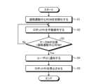
- FIG. 8is a flowchart showing an example of alignment between the insertion point I of the surgical tool T and the remote motion center RCM using the marker M.
- step S1the remote motion center RCM is initialized.
- the support device 8grasps the position of the remote motion center RCM in the surgical tool T when the surgical tool T is connected to the robot R2. For example, the position of the remote motion center RCM in the captured image of the camera provided in the support device 8 is registered.
- step S2the user U manually operates the robot R1.
- the user Umanually operates the robot R1 so that the remote motion center RCM is positioned outside the eyeball E (for example, in a state immediately before insertion).
- the user Umanually operates the robot R1 so as to insert the surgical tool T into the eyeball E.
- a marker Mthat is, a remote motion center RCM of the surgical tool T approaches the insertion point I.
- the support device 8monitors the positional relationship between the insertion point I of the surgical tool T and the marker M.
- step S3the support device 8 determines whether or not the position of the marker M matches the remote motion center RCM. If they match (step S3: Yes), the process proceeds to step S4. Otherwise (step S3: No), the process returns to step S2.
- step S4the support device 8 notifies the user U that the insertion point I of the surgical tool T and the remote motion center RCM have coincided.
- step S5the user U stops the robot R1.
- the lock mechanism 6locks all joints.
- the robot R1is fixed while the insertion point I of the surgical tool T and the remote motion center RCM are aligned.
- the marker M provided on the surgical tool T and the support device 8are used to assist the user U in aligning the insertion point I of the surgical tool T with the remote motion center RCM. can be done.
- the robot device 2includes a robot R1 (first robot) and a robot R2 (second robot).
- Robot R1includes a base portion 4 and a distal end portion 5 .
- the robot R2is supported by the distal end portion 5 of the robot R1 and supports a surgical instrument T inserted into the patient's body (for example, the eyeball E).
- the robot R1is configured to be operated (manually operated) by the user U by directly applying force to the robot R1.
- the user Ucan easily align the surgical tool T by manually operating the robot R1.
- the robot R1may include the locking mechanism 6 that locks the joints. This allows switching between locking and unlocking of the joints. For example, it is possible to reduce the need for the user U to spend a lot of time moving the insertion point I of the surgical tool T, which must be frequently performed during surgery.
- the lock mechanism 6may include an electromagnetic brake that unlocks the joint when voltage is applied and locks the joint when voltage is not applied. As a result, it is possible to reduce the risk of the robot device 2 running out of control due to, for example, a power outage.
- the lock mechanism 6may be provided on the base portion 4 as described with reference to FIG. Thereby, the configuration of the distal end portion 5 can be simplified.
- the robot R1includes the transmission 7 that transmits the braking force from the lock mechanism 6 to the joints.
- At least one of hydraulics, pneumatics, dielectric elastomers and shape memory alloysmay be used to transfer the braking force from locking mechanism 6 to the joint. This makes it possible to reduce the size and weight of the device as compared with the case of using a driving force transmission system using gears, for example.
- the transmission 7may be provided on the base portion 4 . Thereby, the configuration of the distal end portion 5 can be simplified.
- the base portion 4may have three translational degrees of freedom, and the distal end portion 5 may have two or more rotational degrees of freedom.
- the robot R1by giving the robot R1 a large number of degrees of freedom by means of the base portion 4 and the distal end portion 5, it is easy to move the robot R1 to a position or to give the robot R1 an arbitrary posture. I will be able to do it.
- the robot R2may be detachably attached to the distal end portion 5 (for example, the rotation mechanism 51) of the robot R1.
- the robot R1can be used repeatedly, and the robot R2 can be made disposable.
- the robot R2may be configured to be remotely operable. This makes remote surgery possible.
- the surgical tool Tmay have a marker M physically provided at a position corresponding to the remote motion center RCM of the surgical tool T. This facilitates alignment between the insertion point I of the surgical tool T and the remote motion center RCM.
- the robot R1has a size that allows the user U to hold and operate it with one hand, and the robot R2 may be smaller than the robot R1.
- the robot device 2By configuring the robot device 2 with such small-sized robots R1 and R2, handling of the robot device 2 including manual operation of the robot R1 can be facilitated.
- the robot system 1 described with reference to FIGS. 1, 5 to 8, etc.is also one of the disclosed technologies.
- the robot system 1includes the robot device 2 and the support device 8 described above.
- the support device 8supports the operation of the robot R1 by the user U for aligning the insertion point I of the surgical tool T and the remote motion center RCM of the surgical tool T.
- FIG.For example, the support device 8 notifies the user U of the positional deviation between the insertion point I of the surgical tool T and the remote motion center RCM.
- the support device 8detects the positional deviation between the insertion point I of the surgical tool T and the remote motion center RCM based on the change in the observation image of the microscope MC that observes the surgical field while the surgical tool T is rotating. good.
- the support device 8may detect the positional deviation between the insertion point I of the surgical tool T and the remote motion center RCM based on the reaction force from the insertion point I of the surgical tool T when the surgical tool T is rotated. . This makes it easier to align the insertion point I of the surgical tool T with the remote motion center RCM.
- the support device 8includes the insertion point I of the surgical tool T and the marker M physically provided on the surgical tool T at a position corresponding to the remote motion center RCM.
- the user Umay be notified that the positions of are matched. In this way, it is also possible to assist the user U in operating the robot R1.
- the robot system 1is an ophthalmic surgery support robot system, and includes a fine motion robot (robot R2), a coarse motion robot arm (robot R1) that supports the fine motion robot (robot R2) in series at the distal end 5, may be provided.
- a fine motion robotrobot R2
- the operatormay manually move the position/orientation of the coarse motion robot arm or stop it.
- the coarse robot armmay have a joint lock ON/OFF mechanism (for example, the lock mechanism 6).
- the coarse motion robot armmay have a self-weight compensation function (for example, the counterweight 42 provided on the base portion 4).
- the coarse motion robot armmay be a passive robot arm having at least three degrees of freedom in position and orientation.
- the coarse robotic armmay have a compact and lightweight structure.
- the joint rotation angles of the coarse robot armmay be measured by sensors, and the position/orientation of the distal end of the arm from the base may be calculated by solving the kinematics.
- the coarse robotic armmay have rotational degrees of freedom at its distal end (eg distal end 5) by means of a gimbal or ball joint (eg rotation mechanism 51).
- a fine motion robotmay be an active robot arm with a mechanical remote center of rotation.
- the robot R2has at least one degree of freedom, has a remote center of rotation (remote center of motion RCM), and may be actively driven.
- Robot R2may have a compact and lightweight structure.
- the robot R2has a parallel link mechanism.
- a slider mechanism that linearly moves the surgical instrument in the insertion direction from the base of the parallel link mechanismmay be connected to the parallel link mechanism.
- a configuration without a slider mechanismis also possible.
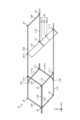
- a robot R2 capable of linearly moving a surgical instrument in the insertion direction from the root of a parallel link mechanism without using a slider mechanismis called a support arm device 20, and will be described with reference to FIGS. 9 to 13.
- the coordinate system for the support arm device 20 shown in FIGS. 9 to 13may be defined separately from the coordinate system for the robot R2 shown in FIG. 1 and the like described above.
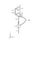
- FIG. 9 and 10are diagrams schematically showing an example of a schematic configuration of the support arm device 20.
- FIG. 9an XYZ coordinate system is shown.
- the X-axis direction, Y-axis direction, and Z-axis directioncorrespond to the front-rear direction, lateral direction, and vertical direction of the support arm device 20 .
- FIG. 9schematically shows the general configuration of the support arm device 20 when viewed from the side (in the positive direction of the Y-axis).
- FIG. 10schematically shows some elements of the support arm device 20 when viewed from the front (in the negative direction of the X-axis).
- the elements indicated by dashed linesare positioned behind (on the negative side of the X-axis) the elements indicated by solid lines.
- the support arm device 20supports the surgical instrument T on the distal end side (X-axis positive direction side).
- the support arm device 20includes a parallel link mechanism 21 , a connection mechanism 22 and a support member 23 .
- the parallel link mechanism 21extends in the XZ plane direction (the surface direction of the first plane). That is, the parallel link mechanism 21 has two degrees of freedom in the X-axis direction and Z-axis direction. There is no degree of freedom in the Y-axis direction.
- the parallel link mechanism 21is configured including multiple joints and multiple links.
- FIG. 9illustrates joints J1 to J9 as a plurality of joints of the parallel link mechanism 21.
- the joint J1 and the joint J2are arranged at the base of the parallel link mechanism 21 (of the support arm device 20).
- the base of the parallel link mechanism 21is the end of the parallel link mechanism 21 opposite to the distal end side.
- the joint J1 and the joint J2are rotationally driven by an actuator (not shown) or the like. Mechanical parts such as actuators are collectively arranged at the base of the parallel link mechanism 21 .
- Each of the multiple linksextends in the XZ plane direction and is connected between joints.
- link L12is connected between joint J1 and joint J2.
- Link L13is connected between joint J1 and joint J3.
- Link L24is connected between joint J2 and joint J4.
- Link L34is connected between joint J3 and joint J4.
- Link L35is connected between joint J3 and joint J5.
- Link L46is connected between joint J4 and joint J6.
- Link L57is connected between joint J5 and joint J7.
- Link L58is connected between joint J5 and joint J8.
- Link L79is connected between joint J7 and joint J9.
- Link L89is connected between joint J8 and joint J9.
- the parallel link mechanism 21includes three parallel link mechanisms, a parallel link mechanism located on the root side, a parallel link mechanism located on the distal end side, and a parallel link mechanism connected therebetween.
- the parallel link mechanism positioned on the root sideincludes joints J1 to J4, link L12, link L13, link L24 and link L34.
- the parallel link mechanism located on the distal end sideincludes joint J5, joints J7 to J9, link L57, link L58, link L79 and link L89.
- a parallel link mechanism connected between themincludes joints J3 to J6, link L34, link L35, link L46 and link L58.
- the link L89is a link (support link) that supports the surgical instrument T on the distal end side.
- the link L89is connected to the surgical tool T via the support member 23 and supports the surgical tool T.
- the link L89, the support member 23, and the surgical instrument Textend in the insertion direction of the surgical instrument T into the body.
- the link L57is a link (opposing link) that faces the link L89, and extends in the insertion direction of the surgical instrument T similarly to the link L89. In the inserting direction of the surgical instrument T, the surgical instrument T, the link L89 and the link L57 are translated together.
- the joint J5is a joint (first joint) connected to one end of the link L57.
- Joint J7is a joint (second joint) connected to the other end of link L57.
- the joint J1is a joint (third joint) arranged at the base of the parallel link mechanism 21 together with the joint J2 and driven to rotate.
- the surgical tool Tcan be moved in the XZ plane direction from the base of the parallel link mechanism 21.
- rotation from the rootcan cause the surgical tool T to pivot or move in the direction of insertion.
- the support arm device 20supports the surgical tool T so that the surgical tool T has a remote motion center RCM. Specifically, the support arm device 20 supports the surgical tool T so that the intersection of the straight line connecting the joints J1 and J2 and the surgical tool T is set at the remote motion center RCM. In the example shown in FIG. 9, the remote motion center RCM of the surgical tool T is located at the same position as the joints J1 and J2 in the Z-axis direction.
- connection mechanism 22is connected to the joints of the parallel link mechanism 21 so as to linearly move the surgical instrument T from the base of the parallel link mechanism 21 in the insertion direction.
- the connection mechanism 22is connected between joint J7 and joint J1.
- the connection mechanism 22deforms in the plane direction of the second plane that intersects the XZ plane so that the joint J7 moves relative to the joint J1 in the extending direction of the link L57 (that is, the insertion direction of the surgical instrument T).
- the second planeshall be the YZ plane orthogonal to the XZ plane, unless otherwise specified.
- connection mechanism 22is deformed on the YZ plane so that the joint J5, the joint J7, the joint J1 and the connection mechanism 22 are positioned on the YZ plane. That is, the connection mechanism 22 deforms such that the YZ plane passing through the joints J5, J7 and J1 is constrained.
- connection mechanism 22includes a link mechanism that rotates on the YZ plane.
- the surgical instrument Tmoves in the insertion direction according to the deformation of the connection mechanism 22 .
- the amount of movement of the surgical tool Talso changes according to the amount of deformation of the connection mechanism 22 .
- connection mechanism 22includes a link mechanism that deforms to have a V shape on the YZ plane.
- a joint 22J, a link 22L1 and a link 22L2are exemplified as elements of the link mechanism of the connection mechanism 22.
- FIG. A link 22L1, a joint 22J and a link 22L2are connected in this order between the joint J7 and the joint J1.
- the joint J7moves closer to the joint J1.
- the joint J7moves downward, that is, in the direction in which the surgical instrument T is inserted.
- the link L57 and the joint J5move in the same direction together with the joint J7, and the link L89 facing the link L57 also moves in the same direction.
- the surgical instrument T supported by the link L89 via the support member 23moves in the advancing direction of its insertion.
- the joint J7moves away from the joint J1.
- the joint J2advances in the Y-axis negative direction
- the joint J7moves upward, that is, in the backward direction of insertion of the surgical instrument T.
- the link L57 and the joint J5move in the same direction together with the joint J7, and the link L89 facing the link L57 also moves in the same direction.
- the surgical instrument T supported by the link L89 via the support member 23moves in the backward direction of its insertion.
- connection mechanism 22For example, by utilizing the deformation of the connection mechanism 22 as described above, the joint J7 and the link L57 can be moved parallel to the insertion direction of the surgical instrument T. As a result, it is possible to linearly move the surgical instrument T in the insertion direction from the base of the parallel link mechanism 21 .
- the parallel link mechanism 21has no degree of freedom in the Y-axis direction, so even if the connection mechanism 22 is deformed, the joints J5, J7, and J1 do not move in the Y-axis direction. Also, since the connecting mechanism 22 deforms on the YZ plane rather than the XZ plane, even if the connecting mechanism 22 deforms, the joints J5, J7, and J1 do not move in the X-axis direction. As a result, the three joints J5, J7 and J1 are aligned on the same straight line when viewed on the XZ plane. is located. By satisfying this condition, the intersection of the surgical tool T and the straight line connecting the joints J1 and J2 is set as the remote motion center RCM.
- the surgical instrument Tcan be linearly moved in the insertion direction from the base of the parallel link mechanism 21 in which the rotationally driven joint J1 is arranged. can be operated. For example, large sliding friction that occurs in a slider mechanism does not occur. It also increases the possibility of simplifying the structure, facilitating miniaturization, and reducing inertia.
- the support arm device 20can be made compact by folding the connection mechanism 22 (in the above case, its link mechanism). Furthermore, the movable range of the surgical instrument T in the insertion direction can be easily widened compared to when a slider mechanism is used. This is because, in the case of a slider mechanism, countermeasures such as lengthening the slider are required, but this is often difficult due to size restrictions and the like.
- connection mechanism 22Several modifications of the connection mechanism 22 will be described with reference to FIGS. 11 to 13.
- FIG. 11Several modifications of the connection mechanism 22 will be described with reference to FIGS. 11 to 13.
- FIG. 11is a diagram schematically showing an example of a schematic configuration of a connection mechanism 22A according to a modification.
- the illustrated connection mechanism 22Aincludes a link mechanism that deforms to have a plurality of V-shapes on the YZ plane.
- the joint 22AJ1, the joint 22AJ2 and the joint 22AJ3, the link 22AL1, the link 22AL2, the link 22AL3 and the link 22AL4are exemplified.
- a link 22AL1, a joint 22AJ1, a link 22AL2, a joint 22AJ2, a link 22AL3, a joint 22AJ3 and a link 22AL4are connected in this order between the joint J7 and the joint J1.
- joints located on the positive side of the Y-axis and joints located on the negative side of the Y-axisare alternately arranged.
- the joints 22AJ1, 22AJ2, and 22AJ3are positioned on the positive Y-axis side.
- the joint 22AJ2is located on the Y-axis negative direction side.
- Such joints and linksallow deformation to have multiple V-shapes. It can be folded more compactly than when deformed to have a single V shape (Fig. 10). It also increases the possibility that the range of motion will be further expanded.
- FIG. 12is a diagram schematically showing an example of a schematic configuration of a connection mechanism 22B according to a modification.
- the illustrated connection mechanism 22Bincludes an elastic body that elastically deforms on the ZY plane. Examples of elastic bodies are leaf springs and the like.
- the connection mechanism 22Bincludes a leaf spring that deforms to have a U shape on the ZY plane.
- the connection mechanism 22Balso functions in the same manner as the connection mechanism 22 (FIG. 10) and the connection mechanism 22A (FIG. 11) described so far.
- FIG. 13is a diagram schematically showing an example of a schematic configuration of a connection mechanism 22C according to a modification.
- the illustrated connection mechanism 22Cincludes an elastic body that deforms to rotate one or more turns on the YZ plane.
- the connection mechanism 22Calso functions in the same manner as the connection mechanism 22 (FIG. 10) and the connection mechanism 22A (FIG. 11) described so far. Note that the elastic body may be deformed so as to be wound up or unrolled on the YZ plane.
- the second plane that intersects the XZ planeis the YZ plane that is orthogonal to the XY plane
- the second planedoes not have to be orthogonal to the XY plane.
- Various planes other than the XY planecan be the second plane.
- the parallel link mechanism 21 and the connection mechanism 22can also be assembled like origami. Such modifications will be described with reference to FIGS. 14 to 17.
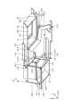
- FIG. 14is a diagrammatic representation of the parallel link mechanism 21 and the connection mechanism 22.
- FIG. 14 and 15are diagrams showing examples of schematic configurations of the parallel link mechanism 21 and the connection mechanism 22 according to the modification.
- the parallel link mechanism 21 and the connection mechanism 22are configured using a plate-like member that can be bent so as to have a hinge structure.
- a bent portion of the plate memberfunctions as a joint.
- the portion connecting the folded portionsfunctions as a link.
- the portion of the plate member corresponding to the jointwill be simply referred to as a joint portion or the like.
- a portion of the plate member corresponding to the linkis also simply called a link portion or the like.
- the joint portion of the plate-shaped memberis configured to be flexible and elastically deformable (for example, it has a hinge structure).
- the joint partis softer than the link part.
- the link portionhas a higher stiffness than the joint portion.
- the thickness of the joint portionmay be smaller than the thickness of the link portion.
- the joint portionmay have one or more pores (pores). By having a smaller thickness or having holes, the joint portion is softer than the link portion and is easier to bend.
- the plate-shaped memberexamples include carbon, iron, and the like.
- the plate membermay be constructed of a composite material. In that case, different materials may be used for the joint portion and the link portion.
- the joint portionis made of a softer material (for example, a material having a different Young's modulus, etc.) than the link portion. Examples of materials for such articulations are polyimide, rubber, silicone, elastomers, and the like.
- the joint J1is composed of a joint J1-1 and a joint J1-2 located at different positions in the X-axis direction.
- the joint J1-2is located on the opposite side of the joint J1 with the joint J1-1 interposed therebetween.
- the joint J1-1 and the joint J2are the drive shafts, and the intersection of the straight line connecting the joint J1-1 and the joint J2 and the surgical tool T (FIG. 1, etc.) is set as the remote motion center RCM.
- a connecting mechanism 22is connected between the joint J1-2 and the joint J7.
- the position of the joint J1-1may be any position between the joints J1-2 and J2.
- the joint J5is composed of a joint J5-1 and a joint J5-2 located at different positions in the X-axis direction.
- Joint J5-2is located on the opposite side of joint J6 across joint J5-1.
- Joint J5-2is a joint (first joint) connected to one end of link L57.
- the link L57is a link that faces the link L89 (opposing link) and moves in parallel together with the link L89.
- the position of joint J5-1may be any position between joint J5-2 and joint J6.
- the portion between the joints J1-2 and J2 in the parallel link mechanism 21 and the portion between the joints J5-2 and J6are connected.
- Examples of elements used for this connectioninclude joint J10, joint J11, joint J12, link L1011 and link L1112.
- the joint J10is provided between the joint J12-1 and the joint J2.
- the joint J12is provided between the joint J5-2 and the joint J6.
- a link L1011, a joint J11 and a link L1112are connected in this order between the joint J10 and the joint J12.
- the plate-shaped members that constitute the parallel link mechanism 21 and the connection mechanism 22are a plurality of plate-shaped members that are partially glued together. As an example, a configuration in which two plate members are pasted together to assemble the parallel link mechanism 21 and the connection mechanism 22 will be described with reference to FIGS. 16 and 17.
- FIG. 16a configuration in which two plate members are pasted together to assemble the parallel link mechanism 21 and the connection mechanism 22 will be described with reference to FIGS. 16 and 17.
- FIG. 16A and 16Bare diagrams showing an example of assembly of the parallel link mechanism 21 and the connection mechanism 22.
- the plate-like member P1corresponds to the upper side (Z-axis positive direction side) of the parallel link mechanism 21 and the connection mechanism 22 .
- the plate member P2corresponds to the lower side (Z-axis negative direction side) of the parallel link mechanism 21 and the connection mechanism 22 .
- the joints and links corresponding to the plate-like member P1 and the plate-like member P2are as indicated by reference numerals in FIG.
- Each of the plate-like member P1 and the plate-like member P2has a lamination portion C1, a lamination portion C2, and a lamination portion C3.
- the bonded portion C1is connected to the joint J4.
- the bonded portion C2is connected to the joint 22J.
- the bonded portion C3is connected to the joint J11.
- FIG. 17is a diagram showing an example of a schematic configuration of the assembled parallel link mechanism 21 and connection mechanism 22.
- FIG. 17In a state in which each part of the plate-like member P1 and the plate-like member P2 is bent, the laminating portions C1 to C3 are laminated to each other.
- the laminated portion C1, the laminated portion C2, and the laminated portion C3 of the plate-like member P1 and the laminated portion C1, the laminated portion C2, and the laminated portion C3 of the plate-shaped member P2are joined in a state of being in surface contact with each other.
- the joining meansis not particularly limited, an adhesive or the like may be used, for example.
- the support arm device 20 including the parallel link mechanism 21 and the connection mechanism 22 as described aboveis specified, for example, as follows.
- the support arm device 20includes a bendable plate member that constitutes the parallel link mechanism 21 and the connection mechanism 22.
- the bent portions (joint portions) of the plate members )function as joints, and the portions (link portions) connecting the bent portions of the plate member function as links.
- the surgical instrument Tis moved from the base of the parallel link mechanism 21 in which the rotationally driven joint J1-1 is arranged.
- Linear motioncan be performed in the insertion direction.
- the thickness of the linkcan be reduced by using the plate member. Accordingly, for example, the operation area of the parallel link mechanism 21 is expanded. It is also possible to reduce the weight of the parallel link mechanism 21 and the connection mechanism 22 as a whole. Since the function of the joint is realized by the bent portion of the plate-like member, it is possible to avoid rattling that may occur when bearings or the like are used, for example. Since backlash does not occur, it is possible to improve the control accuracy of the rotational position accordingly.
- the bent portions (joint portions) of the plate-like memberare elastically deformable, and the portions (link portions) connecting the bent portions in the plate-like member may have higher rigidity than the bent portions.
- a plate-like membercan be used to realize joint and link functions.
- the plate-like memberincludes a plurality of plate-like members (for example, plate It may be a shaped member P1 or a plate-shaped member P2).
- the parallel link mechanism 21 and the connection mechanism 22can be easily manufactured simply by sticking plate members together.
- FIG. 18is a diagram showing an example of the schematic configuration of the robot R1 and the robot R2.
- the robot R2which is the support arm device 20 made up of a plate member as described above, is used while being supported by the distal end portion 5 of the robot R1.
- Robot R1has 6 degrees of freedom, ie, 3 degrees of freedom in translation at the base portion 4 and 3 degrees of freedom in rotation at the distal end portion 5 has been described as an example.
- the degrees of freedom of the robot R1are not limited to six.
- Robot R1may have less than 6 degrees of freedom or more than 6 degrees of freedom.
- robot R1may have 5 or more degrees of freedom.
- the degree of freedom of the robot R2is not limited to three.
- the robot R2may have one or more degrees of freedom.
- robot R2may have, for example, four degrees of freedom or less.
- the four degrees of freedominclude, for example, two degrees of freedom in the parallel link mechanism of the robot R2 and one degree of freedom in the insertion direction of the surgical tool T, as well as one degree of freedom in rotation of the surgical tool T such as forceps around the long axis. .
- the degrees of freedom of the robot R2By setting the degrees of freedom of the robot R2 to 4 or less, it is possible to prevent the degrees of freedom from becoming too redundant.
- the surgical tool Tdoes not change its shape even if it rotates in the long axis direction, such as an injection needle, one degree of freedom in rotation is not necessary, and the robot R2 has three or less degrees of freedom. good.
- surgical tools Tmay be used as the surgical tool T.
- surgical instruments Tare forceps, electric scalpels, injection needles, endoscope probes, and the like.
- the surgical tool Twhich is forceps
- FIG. 1the surgical tool T, which is an injection needle, will be described with reference to FIG. 19 as well.
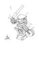
- FIG. 19is a diagram showing an example of the schematic configuration of the robot device 2.
- the surgical tool T supported by the robot R2 of the robot device 2is an injection needle. Since the injection needle only needs to move in the longitudinal direction, the robot R2 may have only one degree of freedom in the insertion direction of the surgical tool T.
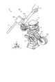
- a retraction mechanismmay be provided between the robot R1 and the robot R2. Description will be made with reference to FIGS. 20 to 32. FIG.
- FIG. 20is a diagram showing an example of a schematic configuration of the robot device 2.
- the robot device 2further includes a retraction mechanism 101 .
- the retraction mechanism 101is provided between the robot R1 and the robot R2.
- the retracting mechanism 101is configured to retract the surgical tool T away from the surgical site when the robot R2 supporting the surgical tool T runs out of control.
- the savingmay be an active saving performed by a user's operation, or a passive saving performed automatically without a user's operation.
- Various known mechanisms configured to perform such retractionmay be used as the retraction mechanism 101 .
- the retraction mechanism 101may be configured to achieve both active retraction and passive retraction by combining the nonlinear characteristics of the magnet attraction force and the linear characteristics of the spring elasticity. A specific description will be given.
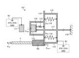
- FIG. 21is a schematic diagram showing a schematic configuration example of the retraction mechanism 101.
- FIG. FIG. 22is a diagram for explaining the force applied to each part in the configuration shown in FIG. 21.
- the robot R1corresponds to mechanical GND.
- the retraction mechanism 101includes a first member 118 , a second member 110 , a third member 115 , magnets 111 and 112 , springs 113 and 116 , and a link mechanism 117 .
- the magnet 111is referred to as the fixed magnet 111 and the magnet 112 is referred to as the biasing magnet 112 in order to distinguish between the magnets 111 and 112 .
- the fixed magnet 111 and the biasing magnet 112for example, a first mechanism that biases the first member 118 in the first direction (the direction from the biasing magnet 112 toward the fixed magnet 111).
- the second member 110 and the spring 113constitute, for example, a second mechanism that biases the first member 118 in a second direction opposite to the first direction.
- the spring 116constitutes a third mechanism that biases the first member 118 in the second direction through the second member 110 and the biasing magnet 112 .
- the fixed magnet 111 and the third member 115are fixed in the system of the retraction mechanism 101 (mechanical GND).
- the fixed magnet 111 and the third member 115are fixed to the tip of the arm of the robot R1 on which the retraction mechanism 101 is mounted.
- the second member 110is arranged so that a position a predetermined distance away from the third member 115 is the reference position. In other words, the second member 110 is separated from the third member 115 by the clearance distance while in contact with the fixed magnet 111 .
- the second member 110is urged in the direction opposite to the fixed magnet 111 (rightward in the drawing) by a spring 116 having one end fixed to the third member 115 .
- the spring 116may be various springs such as, for example, a coil spring or a leaf spring.
- the spring 116is not limited to a metal spring such as a coil spring or a leaf spring, and may be, for example, a comb spring, an air spring, a liquid spring, or the like.
- various elastic bodiessuch as a diaphragm may be used for the spring 116 .
- a robot R2is fixed to the second member 110 to support a surgical tool T for treating a patient.
- the surgical tool T and the robot R2may be simply referred to as the surgical tool T hereinafter.
- the direction in which the surgical instrument T is attached to the second member 110may be, for example, the opposite direction (leftward in the drawing) to the direction in which the second member 110 is biased by the spring 116 (rightward in the drawing).
- the biasing magnet 112is arranged to face the fixed magnet 111 with the second member 110 interposed therebetween. At this time, the biasing magnet 112 is arranged so that its magnetization direction is the direction (horizontal direction in the drawing) in which it exerts an attractive force with the fixed magnet 111 .
- This biasing magnet 112is fixed to the first member 118 .
- the first member 118is biased by a spring 113 having one end fixed to the second member 110 in a direction (rightward in the drawing) opposite to the attracting direction between the fixed magnet 111 and the biasing magnet 112 .
- the spring 113may be made of various elastic bodies such as a coil spring or a leaf spring. In this case, the elastic force of the spring 113 and the elastic force of the spring 116 may have characteristics with different inclinations or characteristics with the same inclination.
- the spring 113 and/or the spring 116is an elastic body having an elastic characteristic in which the magnitude of the force linearly changes according to the position of the first member 118 with respect to the fixed magnet 111. is exemplified, but it is not limited to this, and an elastic body having elastic characteristics in which the magnitude of force changes non-linearly may be used.
- the second member 110has a force (restoring force) k A ⁇ x A (a leftward force in the drawing) that is pushed toward the fixed magnet 111 side by the biasing magnet 112 . ) and a force (restoring force) k B ⁇ x B (rightward force in the drawing) pulled by the spring 116 to the side opposite to the fixed magnet 111 .
- the spring 113will also be referred to as a spring A
- the spring 116will also be referred to as a spring B.
- kAis the spring constant of spring A
- kBis the spring constant of spring B
- ⁇ xAis the amount of displacement of spring A from its natural length
- ⁇ xBis the amount of displacement of spring B from its natural length.
- the force applied to the first member 118 by the fixed magnet 111, the biasing magnet 112, and the spring A supported by the second member 110(which is referred to as force f11) is the force between the fixed magnet 111 and the biasing magnet 112.
- force f11the force applied to the first member 118 by the fixed magnet 111, the biasing magnet 112, and the spring A supported by the second member 110
- force f11the force between the fixed magnet 111 and the biasing magnet 112.
- force f12the force applied to the second member 110 by the fixed magnet 111, the biasing magnet 112, and the spring B supported by the third member 115 (this force is referred to as force f12) is the force between the fixed magnet 111 and the biasing magnet 112.
- the link mechanism 117may be, for example, a thread, a wire, a rod-shaped member, or the like. However, not limited to these, for example, pneumatic pressure, hydraulic pressure, link, shape memory, soft actuator, etc., which can remotely apply a traction force to the first member 118 (more specifically, the biasing magnet 112) If so, various changes may be made.
- the first member 118is omitted and the spring 113 and link mechanism 117 are directly attached to the biasing magnet 112 .
- the spring 113is also referred to as a spring A
- the spring 116is also referred to as a spring B
- the fixed magnet 111is also referred to as a magnet B
- the biasing magnet 112is also referred to as a magnet A.
- a system 1that initiates a retraction operation (active retraction operation) triggered by the fact that the traction force (internal force) fs of the link mechanism 117 reaches a first threshold value;
- a system 2that initiates a retraction operation (passive retraction operation) triggered by the fact that the external force ft applied to the surgical tool T reaches a second threshold value.
- m1is the mass of the second member 110
- mAis the mass of the biasing magnet 112 (magnet A)
- mBis the mass of the stationary magnet 111 (magnet B)
- NAis the mass of the system 1.
- the normal force received by magnet A from second member 110is normal force received by magnet A from second member 110.
- NBis the normal force received by magnet A from second member 110 in system 2.
- f magis magnet AB.
- ftmay be the acting force (external force) at the distal end of the surgical instrument T, and fs may be the pulling force (internal force) of the link mechanism 117 .
- the equation of motion of the magnet A(the biasing magnet 112, corresponding to the first member 118) can be expressed by the following equation (1)
- the equation of motion of the second member 110can be represented by the following equation (2).
- the attractive force f mag between the fixed magnet 111 and the biasing magnet 112varies depending on the position of the biasing magnet 112 or the first member 118 with respect to the fixed magnet 111. It has characteristics that change non-linearly. Specifically, the attractive force f mag has a characteristic of decreasing exponentially (nonlinearly) in inverse proportion to the distance between the magnets.
- Kis a constant
- d0is the distance between the magnets (equivalent to the thickness of the second member 110) when the biasing magnet 112 is closest to the fixed magnet 111
- dis the distance that the biasing magnet 112 moves away from the stationary magnet 111 .
- the biasing magnet 112is moved from the fixed magnet 111 to a distance (d 0 +d) where the attractive force f mag (d) between the magnets becomes smaller than the restoring force k A ⁇ x A of the spring 113 .
- the restraint of the urging magnet 112 by the fixed magnet 111is released, and the first member 118 suddenly moves toward the third member 115 by the restoring force k A ⁇ x BA of the spring 113 and the pulling force f s of the link mechanism 117 . do.
- the second member 110moves a clearance distance (for example, 5 mm) between the second member 110 and the third member 115, and comes into contact with the third member 115 and stops.
- a clearance distancefor example, 5 mm
- FIGS. 30 and 31are diagrams for explaining an operation example at the time of passive evacuation according to this embodiment.
- the biasing magnet 112is moved from the fixed magnet 111 to a distance (d 0 +d) where the attractive force f mag (d) between the magnets becomes smaller than the restoring force k B ⁇ x B of the spring 116 .
- the restraint of the biasing magnet 112 by the fixed magnet 111is released, and the second member 110 suddenly moves due to the restoring force k B ⁇ x B of the spring 116 and the force f s +f t applied to the surgical instrument T and the link mechanism 117 . to the direction of the third member 115 (passive retraction).
- the second member 110moves a clearance distance (for example, 5 mm) between the second member 110 and the third member 115, and comes into contact with the third member 115 and stops.
- a clearance distancefor example, 5 mm
- the system 1 that implements active evacuation and the system 2 that implements passive evacuationare different systems. Therefore, it is possible to automatically execute each by using forces of different magnitudes as triggers. For example, it is possible to achieve both active retraction using an ergonomically appropriate operating force and passive retraction using an operating force corresponding to an external force.
- Robot R1may have five or more degrees of freedom.
- Robot R2may have up to four degrees of freedom.
- Robot R2may also include actuators and be actively driven. For example, by using such robots R1 and R2, it is possible to prevent the degrees of freedom from becoming excessively redundant while ensuring the necessary motions.
- the robot device 2includes the safety retraction mechanism 101 and the like provided between the robots R1 and R2, and the retraction mechanism includes the first member 118, a second member 110; a first mechanism for stopping the first member 118 by urging the first member 118 toward the second member 110; A second mechanism for unstopping member 118 and a third mechanism for unstopping first member 118 by the first mechanism in response to a force applied to second member 110 may be included. As a result, it becomes possible to perform the retraction operation safely.
- the surgical tool Tmay include an injection needle. Such positioning of the surgical tool T is also possible.
- a first robotincluding a base and a distal end; a second robot supported by the distal end of the first robot and supporting a surgical instrument to be inserted into a patient's body; with The first robot is configured to be operated by a user by directly applying force to the first robot.
- robotic device(2)
- the first robotincludes a locking mechanism that locks joints, The robot device according to (1).
- the locking mechanismincludes an electromagnetic brake that unlocks the joint when voltage is applied and locks the joint when voltage is not applied.
- the locking mechanismis provided on the base portion, The robot device according to (2) or (3).
- the first robotincludes a transmission that transmits braking force from the locking mechanism to the joint;
- the transmissionuses at least one of wires, wire ropes, belts, steel belts, hydraulics, pneumatics, dielectric elastomers, and shape memory alloys to transmit the braking force from the locking mechanism to the joint.
- the robot deviceaccording to any one of (2) to (4). (6) wherein the transmission is provided on the base portion;
- the base portionhas three translational degrees of freedom; the distal end has two or more rotational degrees of freedom;
- the second robotis removably attached to the distal end of the first robot;
- the second robotis configured to be remotely operable;
- the surgical toolhas a marker physically provided at a position corresponding to the remote center of motion of the surgical tool;
- the first robothas a size that can be held and operated by a user with one hand, the second robot is smaller than the first robot;
- the surgical instrumentis inserted into the patient's eyeball,
- the first robothas 5 or more degrees of freedom,
- the second robothas 4 or less degrees of freedom, the second robot includes an actuator and is actively driven;
- a retraction mechanism provided between the first robot and the second robotis a first member; a second member; a first mechanism for stopping the first member by biasing the first member toward the second member; a second mechanism that releases the stop of the first member by the first mechanism according to the force applied to the first member; a third mechanism that releases the stop of the first member by the first mechanism according to the force applied to the second member; including, The robot device according to any one of (1) to (13).
- the surgical instrumentincludes an injection needle, The robot device according to any one of (1) to (14).
- a robotic devicea support device; with The robotic device is a first robot including a base and a distal end; a second robot supported by the distal end of the first robot and supporting a surgical instrument to be inserted into a patient's body; including The first robot is configured to be operated by a user by directly applying force to the first robot, The support device supports the operation of the first robot by the user for aligning an insertion point of the surgical tool and a remote motion center of the surgical tool. robot system.
- the support devicenotifies the user of a positional deviation between the insertion point of the surgical tool and the center of remote movement of the surgical tool.
- the robot systemaccording to (16).
- the support devicedetects a positional deviation between the insertion point of the surgical tool and a remote motion center of the surgical tool based on a change in an observation image of a microscope that observes the surgical field when the surgical tool is rotated.
- the robot system according to (16).(19) The support device detects a positional deviation between the insertion point of the surgical tool and a remote motion center of the surgical tool based on a reaction force from the insertion point of the surgical tool when the surgical tool is rotated.
- the support devicenotifies the user U that the position of the insertion point of the surgical tool and a marker physically provided at a position corresponding to the center of remote movement on the surgical tool match.
- the parallel link mechanismis a support link on the distal end side that supports a surgical instrument to be inserted into the patient's body; a counter link facing the support link; a first joint connected to one end of the opposing link; a second joint connected to the other end of the opposing link; a third joint that is arranged at the end opposite to the distal end side and that is rotationally driven; including The connecting mechanism is connected between the second joint and the third joint such that the second joint moves relative to the third joint in the extending direction of the opposing link.
- the robot devicedeforms in the planar direction of a second plane that intersects the first plane;
- the robot deviceany one of (1) to (20).
- (22)A bendable plate-shaped member that constitutes the parallel link mechanism and the connection mechanism, The bent portion of the plate member functions as a joint, A portion connecting the bent portions of the plate member functions as a link, The robot device according to (21).
- (23)The bent portion of the plate member is elastically deformable, A portion connecting the bent portions in the plate-like member has higher rigidity than the bent portion,
- the robot device22).
- the plate-shaped memberis a plurality of plate-shaped members that are partially bonded to each other, The robot device according to (22).
Landscapes
- Engineering & Computer Science (AREA)
- Health & Medical Sciences (AREA)
- Surgery (AREA)
- Life Sciences & Earth Sciences (AREA)
- Robotics (AREA)
- Heart & Thoracic Surgery (AREA)
- Nuclear Medicine, Radiotherapy & Molecular Imaging (AREA)
- Biomedical Technology (AREA)
- Medical Informatics (AREA)
- Molecular Biology (AREA)
- Animal Behavior & Ethology (AREA)
- General Health & Medical Sciences (AREA)
- Public Health (AREA)
- Veterinary Medicine (AREA)
- Mechanical Engineering (AREA)
- Oral & Maxillofacial Surgery (AREA)
- Pathology (AREA)
- Manipulator (AREA)
Abstract
Description
Translated fromJapanese本開示は、ロボット装置及びロボットシステムに関する。The present disclosure relates to a robot device and a robot system.
例えば特許文献1は、マイクロ位置決めアームに接続されるとともに術具が接続された装置を開示する。For example,
例えば、体内への術具の挿入点と遠隔運動中心(RCM:Remote Center of Motion)との位置合わせが必要になる。遠隔運動中心に限らず、術具の位置合わせ技術について検討の余地がある。For example, it is necessary to align the insertion point of the surgical instrument into the body and the remote center of motion (RCM). There is room for examination of positioning techniques for surgical tools, not limited to the remote motion center.
本開示の一側面は、術具の位置合わせを容易にすることが可能なロボット装置及びロボットアームシステムを提供する。One aspect of the present disclosure provides a robotic device and a robotic arm system capable of facilitating alignment of surgical tools.
本開示の一側面に係るロボット装置は、ベース部及び遠位端部を含む第1のロボットと、第1のロボットの遠位端部に支持されるとともに、患者の体内に挿入される術具を支持する第2のロボットと、を備え、第1のロボットは、ユーザが第1のロボットに直接的に力を加えて操作するように構成される。A robotic device according to one aspect of the present disclosure includes a first robot including a base and a distal end, and a surgical instrument supported by the distal end of the first robot and inserted into a patient's body. and a second robot supporting the first robot, the first robot being configured to be manipulated by a user by applying force directly to the first robot.
本開示の一側面に係るロボットシステムは、ロボット装置と、支援装置と、を備え、ロボット装置は、ベース部及び遠位端部を含む第1のロボットと、第1のロボットの遠位端部に支持されるとともに、患者の体内に挿入される術具を支持する第2のロボットと、を含み、第1のロボットは、ユーザが第1のロボットに直接的に力を加えて操作するように構成され、支援装置は、術具の挿入点と術具の遠隔運動中心とを位置合わせするためのユーザによる第1のロボットの操作を支援する。A robotic system according to one aspect of the present disclosure includes a robotic device and a support device, wherein the robotic device includes a first robot including a base and a distal end, and a distal end of the first robot. and a second robot supported by and supporting a surgical instrument to be inserted into the patient's body, the first robot being operable by a user to directly apply force to the first robot. The assisting device assists the user in manipulating the first robot for aligning the insertion point of the surgical tool and the remote motion center of the surgical tool.
以下に、本開示の実施形態について図面に基づいて詳細に説明する。なお、以下の各実施形態において、同一の要素には同一の符号を付することにより重複する説明を省略する。Below, embodiments of the present disclosure will be described in detail based on the drawings. In addition, in each of the following embodiments, the same reference numerals are given to the same elements to omit redundant description.
以下に示す項目順序に従って本開示を説明する。
0.序
1.実施形態
2.変形例
3.効果の例
4.ロボットR2(支持アーム装置)の構成例
5.ロボット装置2の変形例
6.退避機構の実施形態
7.効果の例The present disclosure will be described according to the order of items shown below.
0.
0.序
例えば低侵襲手術においては、体内への術具の挿入点を容易且つ任意に移動させる必要がある。手技の場合には、顕微鏡画像を元に医師が手術を行うが、挿入点は視野外のため、大凡の位置をイメージしながらの手技になる。とくに眼科では、強膜(白目部)に開けられた挿入点に力が加わった場合、裂孔を引き起こすリスクがある。医師は、術具の挿入点の位置を不動点に合わせた状態で、術具先端をμmオーダで精密に操作する必要がある。手振れ等により、挿入点経由で振動が眼球に加わりターゲットが揺れるため、精密な術具先端操作の支障となる難しさがある。手術ロボットを用いる場合は、挿入点を遠隔運動中心(ピボット回転における不動点)に設定する必要がある。挿入点の移動と静止をするうえで、挿入点と遠隔運動中心を正確に位置合わせすることが困難であった。0. Introduction For example, in minimally invasive surgery, it is necessary to easily and arbitrarily move the insertion point of a surgical instrument into the body. In the case of a procedure, a doctor performs surgery based on a microscope image, but since the insertion point is outside the field of view, the procedure is performed while imagining a rough position. Especially in ophthalmology, when force is applied to the insertion point opened in the sclera (white part of the eye), there is a risk of causing a tear. The doctor needs to precisely manipulate the tip of the surgical instrument on the order of μm while the position of the insertion point of the surgical instrument is aligned with the fixed point. Due to camera shake or the like, vibrations are applied to the eyeball via the insertion point, causing the target to sway. When using a surgical robot, it is necessary to set the insertion point to the center of remote motion (fixed point in pivot rotation). Accurate alignment of the insertion point and the remote motion center was difficult in moving and resting the insertion point.
手技の場合、術者自身が手で術具を保持する必要があり、挿入点と遠隔運動中心とを手動で位置合わせする。手術ロボットの場合は、遠隔運動中心に設定すべき挿入点の位置情報をロボットに正確に知らせることが難しい。操作者がロボットアームに直接触れて、ダイレクトティーチングで挿入点を設定する方法があるが、産業用ロボットでは力センサをロボットアームに装着し、人が接触した時に受動的に動作するシステムとして構成される。力センサの故障によるロボットの暴走リスクやアーム構造の大型化が障壁となり、医療でそのまま用いることは出来ない。もしくは、モータ電流値をもとに力推定を行う方法があるが、安定性・信頼性の面でリスクがある。とくにマイクロサージェリのような微細作業が要求される診療科では、数mmの微小な位置ずれが患者組織に有害事象を引き起こす可能性がある。In the case of the procedure, the operator himself needs to hold the surgical instrument by hand, and manually align the insertion point and the remote motion center. In the case of a surgical robot, it is difficult to accurately inform the robot of the positional information of the insertion point to be set at the remote motion center. Although there is a method in which the operator directly touches the robot arm and sets the insertion point by direct teaching, an industrial robot is configured as a system in which a force sensor is attached to the robot arm and moves passively when a human touches it. be. The risk of the robot going out of control due to the failure of the force sensor and the increase in the size of the arm structure are obstacles, and it cannot be used in medical treatment as it is. Alternatively, there is a method of estimating the force based on the motor current value, but there are risks in terms of stability and reliability. Especially in clinical departments requiring fine work such as microsurgery, even a minute displacement of several millimeters may cause an adverse event in the patient's tissue.
手術中に視野変更等が行われる場合も少なくない。その際は、術具の挿入点を移動させる必要がある。改めて術具の挿入点と遠隔運動中心との位置合わせを行わなければならない。例えば、正確な3次元の位置情報をロボットに教えたり、画像情報から挿入点の空間的な位置を自動検出したりすることが考えられる。ただし、ロボット、患者及びカメラ等の間の相対的な空間座標が必要になり、再現性や精度を上げることが困難で、リスクを伴う。It is not uncommon for the field of view to be changed during surgery. In that case, it is necessary to move the insertion point of the surgical instrument. The insertion point of the surgical instrument and the center of remote motion must be aligned again. For example, it is conceivable to teach a robot accurate three-dimensional position information, or to automatically detect the spatial position of an insertion point from image information. However, relative spatial coordinates among the robot, patient, camera, etc. are required, which makes it difficult to improve reproducibility and accuracy, and involves risks.
開示される技術によれば、医師等のユーザは、ロボットに触れる等して直接的に力を加えて操作することが可能である。ロボットが任意の位置、姿勢等になるように動かしたり静止させたりすることができる。ダイレクトティーチングによる術具の位置合わせ、例えば術具の挿入点と遠隔運動中心との位置合わせを容易に行うことができる。According to the disclosed technology, a user such as a doctor can directly apply force to the robot to operate it. The robot can be moved to an arbitrary position, pose, etc., or can be made stationary. Positioning of the surgical tool by direct teaching, for example, positioning of the insertion point of the surgical tool and the center of remote movement can be easily performed.
1.実施形態
図1は、実施形態に係るロボットシステム1の概略構成の例を示す図である。ロボットシステム1は、手術に用いられる。以下では、手術が眼科手術である場合を例に挙げて説明する。手術対象の患者の眼球を、眼球Eと称し図示する。術者(医師等)を、ユーザUと称し図示する。図1には、ユーザUの手の部分が模式的に示される。1. Embodiment FIG. 1 is a diagram showing an example of a schematic configuration of a
ロボットシステム1は、ロボット装置2と、顕微鏡MCと、モニタ3と、ロボットR3と、支援装置8とを含む。先に顕微鏡MC及びモニタ3について述べると、顕微鏡MCは、術野を観察する。顕微鏡MCの視野は、眼球E及び眼球E内の術具T等を含み得る。モニタ3は、顕微鏡MCの観察画像(術野画像)を表示する。ユーザUは、モニタ3に表示された顕微鏡MCの観察画像を見たり、顕微鏡MCの接眼レンズを直視したりすることにより、術野を観察する。術野に映る術具Tと手元のロボット装置2との相対的な位置関係のビジュアルフィードバックを利用した操作により、手術が進められる。The
ロボット装置2は、患者の近くに配置されるロボット(患者側のロボット)であり、互いに直列に連結された2つのロボットを含んで構成される。第1のロボットを、ロボットR1と称し図示する。第2のロボットを、ロボットR2と称し図示する。ロボットR1は、ロボットR2よりも患者の遠くに位置する。ロボットR2は、ロボットR1よりも患者の近くに位置するように、ロボットR1によって支持される。ロボット装置2は、支持アーム装置等とも呼べる。ロボット装置2の空間座標の基準となるベース位置(ベース面)が、MechanicalGNDとして模式的に図示される。The
ロボットR1は、ユーザUが直接的に力を加えて操作するように構成される。ロボットR1は、アクチュエータ、モータ、力センサ等を含まない。ユーザUによるロボットR1の操作を、ロボットR1の手動操作ともいう。例えば、ユーザUは、ロボットR1を把持して動かすことによって、ロボットR1を手動操作する。The robot R1 is configured to be operated by the user U by directly applying force. Robot R1 does not include actuators, motors, force sensors, and the like. The operation of the robot R1 by the user U is also referred to as manual operation of the robot R1. For example, the user U manually operates the robot R1 by holding and moving the robot R1.
ロボットR1は、3以上の自由度を有する。この例では、ロボットR1は、並進3自由度及び回転3自由度を有する。図1において、ロボットR1の並進軸が、Xi軸、Yi軸及びZi軸として示される。ロボットR1の回転軸が、ri軸、pi軸及びyi軸として示される。多くの自由度をロボットR1に持たせることで、ロボットR1を任意の位置に移動させたり、任意の姿勢にしたりすることが容易になる。The robot R1 has 3 or more degrees of freedom. In this example, robot R1 has three translational degrees of freedom and three rotational degrees of freedom. In FIG. 1, the translational axes of robot R1 are indicated as Xi-, Yi-, and Zi-axes. The axes of rotation of robot R1 are shown as the ri, pi and yi axes. By giving the robot R1 a large number of degrees of freedom, it becomes easy to move the robot R1 to an arbitrary position or take an arbitrary posture.
ロボットR2は、ユーザUが直接的に力を加えずとも操作できるように構成される。ロボットR2は、アクチュエータ等を含んで構成される。例えば、ロボットR2は、ロボットR2から離れた位置に設けられたロボットR3の変位量に応じて能動的に動く(駆動される)ように構成される。ユーザUは、ロボットR3を操作することによって、ロボットR2を遠隔操作する。The robot R2 is configured so that the user U can operate it without directly applying force. The robot R2 is configured including actuators and the like. For example, the robot R2 is configured to actively move (is driven) according to the amount of displacement of the robot R3 provided at a position distant from the robot R2. The user U remotely controls the robot R2 by operating the robot R3.
ロボットR2は、術具Tを支持する。術具Tは、患者の体内、この例では眼球E内に挿入される。ロボットR2は、術具Tに遠隔運動中心RCMを有するように、術具Tを支持する。この例では、ロボットR2は、平行リンク機構を備え、そのピボット点(ピボット位置)が遠隔運動中心RCMになる。The robot R2 supports the surgical tool T. The surgical instrument T is inserted into the patient's body, the eyeball E in this example. The robot R2 supports the surgical tool T so that the surgical tool T has a remote center of motion RCM. In this example, robot R2 has a parallel linkage and its pivot point (pivot position) is the remote center of motion RCM.
ロボットR2は、1以上の自由度を有する。この例では、ロボットR2は、3自由度を有し、また、ピボット移動可能である。図1において、ロボットR2のピボット回動軸が、Xe軸、Ye軸及びZe軸として示される。ロボットR2は、遠隔運動中心RCMを回転中心として、眼球E内で術具Tを移動させる。"Robot R2 has one or more degrees of freedom." In this example, robot R2 has three degrees of freedom and is pivotable. In FIG. 1, the pivotal axes of robot R2 are indicated as the Xe, Ye and Ze axes. The robot R2 moves the surgical tool T within the eyeball E with the remote motion center RCM as the center of rotation.
ロボットR2は、精密なアクチュエータ等によって動くので、手動操作されるロボットR1よりも、高精度な(例えば10μm程度の)操作が可能である。この意味において、ロボットR1は粗動ロボットと呼べ、ロボットR2は微動ロボットとも呼べる。なお、ロボットR1には、清潔領域をカバーするためのドレープが固定されてもよい。Since the robot R2 is moved by precision actuators, etc., it can be operated with higher precision (for example, about 10 μm) than the manually operated robot R1. In this sense, the robot R1 can be called a coarse motion robot, and the robot R2 can also be called a fine motion robot. A drape for covering the clean area may be fixed to the robot R1.
ユーザUは、術具Tを眼球Eに挿入するように、ロボットR1を手動で移動させる。眼球Eにおける術具Tの挿入位置を、挿入点Iと称し図示する。ユーザUは、挿入点Iと遠隔運動中心RCMとを位置合わせするように、ロボットR1を手動で移動させる。図1に示されるように、術具Tの挿入点Iと遠隔運動中心RCMとが重なった(同じ位置にある)状態で、手術が進められる。The user U manually moves the robot R1 so as to insert the surgical tool T into the eyeball E. The insertion position of the surgical instrument T in the eyeball E is referred to as an insertion point I and illustrated. The user U manually moves the robot R1 so as to align the insertion point I and the remote motion center RCM. As shown in FIG. 1, the operation proceeds with the insertion point I of the surgical instrument T and the remote motion center RCM overlapping (in the same position).
ロボットR2は、遠隔操作可能に構成される。図1に示される例では、上述のように、ユーザUは、ロボットR3を操作することによって、ロボットR2を遠隔操作する。ロボットR2に対応するロボットR3の軸が、Xu軸、Yu軸及びZu軸として図示される。ロボットR2及びロボットR3は、例えば、双方向通信を利用して、それぞれにおける変位量や力が対応するようにバイラテラル制御される。Robot R2 is configured to be remotely controllable. In the example shown in FIG. 1, the user U remotely controls the robot R2 by operating the robot R3, as described above. The axes of robot R3 that correspond to robot R2 are illustrated as the Xu, Yu and Zu axes. The robot R2 and the robot R3 are bilaterally controlled using, for example, two-way communication so that the amounts of displacement and forces in each correspond.
ロボットR2とロボットR3との間で、相対的な位置関係のスケーリングが行われてよい。図1に示される例では、ロボットR2の物理的な変位量がロボットR3の物理的な変位量よりも小さくなるように(1/K倍になるように)、モーションスケーリング(Motion Scaling)が用いられる。ロボットR3を介したロボットR2の微細な遠隔操作が可能になり、遠隔手術が行い易くなる。A relative positional relationship may be scaled between the robots R2 and R3. In the example shown in FIG. 1, motion scaling is used so that the physical displacement of robot R2 is smaller than the physical displacement of robot R3 (1/K times). be done. Fine remote control of the robot R2 via the robot R3 becomes possible, making remote surgery easier.
なお、ロボット装置2のロボットR1を操作するユーザUと、ロボットR3を操作するユーザUとは、同じであってもよいし、異なっていてもよい。The user U who operates the robot R1 of the
図2は、患者に対するロボット装置2の配置の例を示す図である。ロボット装置2は、ロボットR1が患者の頭部付近の台座に設けられた円弧形状を有するレールに固定され、ロボットR2が患者の眼球Eの近くに位置するように配置される。ロボット装置2のロボットR1について、図3を参照してさらに説明する。FIG. 2 is a diagram showing an example of placement of the
図3は、ロボットR1の概略構成の例を示す図である。ロボットR1は、ベース部4と、遠位端部5と、ロック機構6と、トランスミッション7とを含む。FIG. 3 is a diagram showing an example of the schematic configuration of the robot R1. Robot R1 includes a
ベース部4は、並進自由度を有するように、並進機構41を含む。この例では、並進自由度は、並進3自由度である。並進機構41は、鉛直方向(Z軸方向)及び水平方向(XY平面方向)の並進3自由度を有する平行リンク機構である。The
ベース部4は、下方部分にカウンターウェイト42を含む。カウンターウェイト42は、ロボットR1のバランスを向上させ、それによって自重補償機能をロボットR1に与える。例えば、ロボット装置2のすべての軸がその場をキープできるような自重補償機能が与えられる。The
遠位端部5は、ロボットR1(図1)を支持する。遠位端部5は、回転自由度を有するように、回転機構51を含む。回転自由度は例えば2以上であってよく、この例では、回転自由度は、回転3自由度である。回転機構51の例は、ジンバル機構、ボールジョイント機構等である。The
ロボットR2は、遠位端部5(例えば回転機構51)に対して着脱可能に取り付けられてよい。同じロボットR1に対して異なるロボットR2を着脱することで、ロボットR1を繰り返し用いる(再利用する)ことができ、一方で、ロボットR2をディスポ―サブルにすることができる。The robot R2 may be detachably attached to the distal end portion 5 (for example, the rotating mechanism 51). By attaching and detaching different robots R2 to and from the same robot R1, the robot R1 can be repeatedly used (reused), while the robot R2 can be made disposable.
ロック機構6は、ベース部4に設けられ、ロボットR1の自由度を司る各関節をロックするように、制動力を発生する。各関節と、ロック機構6とは、一対一に対応してよい。各関節を個別にロック(ロックON)したりアンロック(ロックOFF)したりすることができる。ロック機構6は、例えば電磁ブレーキを含んで構成される。電磁ブレーキは、電流が流れていたり電圧が加えられたりしているときに関節をアンロックし、電流が流れていなかったり電圧が加えられていなかったりするときに関節をロックしてよい。ロック機構6の電源をオフにすることで、関節がロックされる。ロック機構6の電源は、例えばユーザUが手動でオン又はオフにする。The
ロック機構6は、関節の角度に応じて回転する支軸を有してよい。支軸に対して、直列に角度センサ(ポテンショメータ、エンコーダ等)が固定されてよい。このような角度センサにより、関節角度の検出が可能になる。関節に直接角度センサを取り付ける必要がない分、小型化、軽量化のメリットが得られ、また、電気配線の数量の低減等も可能になる。角度センサの検出結果を利用して運動力学を解くことで(例えば順運動学による計算により)、ベース部4からの遠位端部5の位置、姿勢が算出される。ロボット装置2の基準位置に対するロボットR2の先端(アーム先端)や術具Tの空間座標を計算することができる。The
各ロック機構6の個別制御が可能である。ロック機構6の制御は、ユーザUが例えばペダル操作等により行ってもよいし、自動で行われてもよい。ベース部4の並進移動のロック及びアンロック、並びに遠位端部5の回転移動のロック及びアンロックを別々に制御することができる。Individual control of each
ロック機構6の電源がオフのときには、ロック機構6によるロックがオンの状態になる。突然の停電が発生した時等でも、ロボット装置2が暴走するリスクが低減又は回避される。ロックがオンになっているロック機構6は、ユーザUがロボットR1を手動で強く推した時に受動的に動くトルクリミッタ的な役割も兼ねる。例えば、緊急時にロボット手術から手技に切り替えることができる。When the power of the
トランスミッション7は、ベース部4に設けられ、ロック機構6からの制動力を、対応する関節に伝達する。図4も参照して説明する。The
図4は、トランスミッション7による制動力の伝達の例を模式的に示す図である。ベース部4の並進機構41(図3)のいくつかの関節にはロック機構6が直接設けられ、従ってトランスミッション7による制動力の伝達は不要である。そのようなロック機構6が、ロック機構6a及びロック機構6fとして例示される。並進機構41の関節のうち、ロック機構6が直接には設けられない関節には、ロック機構6の制動力が、トランスミッション7を介して伝達される。そのようなロック機構6が、ロック機構6bとして例示される。ロック機構6aは直接的に取り付けられてもよいし、減速機(又は増速機)を介して取り付けられてもよい。FIG. 4 is a diagram schematically showing an example of transmission of braking force by the
遠位端部5の関節には、ロック機構6は直接には設けられず、ロック機構6の制動力は、トランスミッション7を介して伝達される。遠位端部5の関節として、関節52c~関節52eが例示される。対応するロック機構6として、ロック機構6c~ロック機構6eが例示される。ロック機構6c~ロック機構6eの制動力が、トランスミッション7b~トランスミッション7eを介して、関節52b~関節52eに伝達される。The
例えば、ロック機構6c~ロック機構6eによるロックをオンにし、ロック機構6a、ロック機構6b及びロック機構6fによるロックをオフにすることで、遠位端部5の回転移動をロックしつつ、ベース部4を並進移動させることができる。ユーザUは、例えば遠位端部5を直接的に保持して移動させたり回転させたりすることができる。For example, by turning on the locking by the locking
トランスミッション7は、歯車による駆動力伝達系は含まない。その分、ロボットR1全体を小型化、軽量化することができる。例えば、トランスミッション7は、ワイヤ、ワイヤロープ、ベルト、スチールベルト、油圧、空圧、誘電エラストマー、形状記憶合金等を用いて、ロック機構6からの制動力を関節に伝達する。図3に示される例では、トランスミッション7は、ワイヤを用いてロック機構6からの制動力を関節に伝達するワイヤトランスミッションである。関節にワイヤロープが固定され、ワイヤロープを介して、関節がロック機構6に連結される。ワイヤ駆動方式で、並進3軸と回転3軸のロック及びアンロックの切り替えることができる。The
図3に戻り、ユーザUは、ロボットR1のベース部4を把持して並進移動させたり、ロボットR1の遠位端部5を把持して回転移動させたりすることにより、ロボットR1を手動操作する。これにより、ユーザUは、遠位端部5に支持されたロボットR2(図1)、ひいてはロボットR2に接続された術具Tを、任意の位置に移動させたり静止させたりすることができる。Returning to FIG. 3, the user U manually operates the robot R1 by gripping the
ロボット装置2の軽量化、小型化が図られている分、ロボットR1の手動操作をはじめとしたロボット装置2の扱いが容易になる。ロボット装置2のロボットR1は、ユーザUが片手で把持して操作できる程度のサイズ、例えば20cm以下の手のひらサイズを有し得る。ロボットR1は、ロボットR2よりもさらに小型化されており、例えば7cm以下のテニスボール程度のサイズを有し得る。As the
粗動ロボットであるロボットR1が小さいので、粗動のスケールも小さくり、振動ノイズが低減される。振動ノイズに対応する共振周波数は、質量に反比例することが知られている。粗動のスケールが小さくなると、質量も小さくなるので、共振周波数は大きくなる。振動ノイズは相対的に小さくなる。また、リンク長が短くなることにより、振動による揺れ幅が相対的に小さくなる。Since the robot R1, which is a coarse motion robot, is small, the scale of coarse motion is also small, and vibration noise is reduced. It is known that the resonant frequency corresponding to vibration noise is inversely proportional to mass. As the scale of coarse motion becomes smaller, the mass also becomes smaller and thus the resonance frequency increases. Vibration noise is relatively small. In addition, since the link length is shortened, the swing width due to vibration is relatively reduced.
以上で説明したロボット装置2によれば、ユーザUがロボットR1を手動操作することで、例えば術具Tの挿入点Iと遠隔運動中心RCMとの位置合わせを容易に行うことができる。より具体的ないくつかの利点について説明する。例えば、ロボットR1がモータや力センサを備えていないので、暴走リスクや故障リスクを低減することができる。According to the
ロボット装置2全体(ロボットアーム全体)を小型化、軽量化できるので、ユーザUが手で持って動かす際に要する力を軽減できる。例えば操作が軽くなる。Since the entire robot device 2 (entire robot arm) can be made smaller and lighter, the force required for the user U to hold and move it can be reduced. For example, it becomes easier to operate.
ベース部4に設けられたロック機構6からの制動力が、トランスミッション7を介して伝達される。ロック機構6がベース部4に設けられることで、遠位端部5の構成すなわち術野周辺の患者側の構成を簡素化することができる。手術時の術具Tとの干渉や顕微鏡MCの視野の阻害リスクを低減し、清潔領域を小型に抑えることできるため運用上メリットが高い。トランスミッション7もベース部4に設けられることによっても、同様の効果が得られる。A braking force from the
ロック機構6によるロック及びアンロックを能動的に切り替えることができる。術中に度々行う必要がある術具Tの挿入点Iの移動にユーザUが多くの時間を費やす必要性が低減される。Locking and unlocking by the
例えば特許文献1に開示されるマクロ位置決めアームは、電動自由度を含む構成となっている。この場合、電動自由度の制御のために、モータ、エンコーダ、力センサ等が必要になり、装置が大型化し、重量も大きくなり、さらには製造上のコストもかかる。また、特許文献1のアームは、ラックアンドピニオンのトランスミッションを利用しており、バックラッシュの問題もある。構造的に重量が増えるため、アクチュエータ出力が大きくなる。例えばこのような問題が、実施形態に係るロボット装置2によって対処される。For example, the macro positioning arm disclosed in
ロック機構6は、患者付近に位置する遠位端部5ではなく、患者から離れたベース部4に設けられる。遠位端部5をコンパクトにすることができ、それによって、例えば他の術具Tとの干渉、術野を遮るオクルージョンや患者との接触といった問題を防ぐことが出来る。The
再び図1を参照して、支援装置8について説明する。支援装置8は、術具Tの挿入点Iと遠隔運動中心RCMとを位置合わせするためのユーザUによるロボットR1の操作を支援する。支援装置8は、例えば汎用のコンピュータ上でソフトウェアを動作させることで実現されてもよいし、専用のハードウェアで実現されてもよい。支援装置8は、ロボットシステム1の他の要素から、必要な情報を通信等によって取得する。例えば、ロボット装置2の状態に関する情報、顕微鏡MCの撮像画像等が取得される。The
支援装置8は、術具Tの挿入点Iと遠隔運動中心RCMとの位置ずれをユーザUに通知する。通知の手法はとくに限定されないが、例えば支援装置8が備えるディスプレイによる表示、スピーカによる音出力等が用いられてよい。ディスプレイとして、モニタ3が用いられてもよい。The
支援装置8は、挿入点Iと遠隔運動中心RCMとの位置ずれを検出する。検出手法のいくつかの例について説明する。The
支援装置8は、術具Tの回転時における顕微鏡MCの観察画像の変化に基づいて、術具Tの挿入点Iと遠隔運動中心RCMとの位置ずれを検出してよい。図5を参照して説明する。The
図5は、術具Tの挿入点Iと遠隔運動中心RCMとの位置ずれの検出の例を示す図である。図示されるように、遠隔運動中心RCMの位置が、挿入点Iの位置からずれている。顕微鏡MCの視野F内に物体O(例えば何らかの生体組織)が位置しており、観察画像には物体Oが含まれる。図5の(B)において矢印で示されるように術具Tが回転すると、挿入点Iと遠隔運動中心RCMとの位置ずれに起因して挿入点Iが移動し、眼球Eが回転する。顕微鏡MCの観察画像内の物体Oの位置も移動する。この移動を検出することで、挿入点Iと遠隔運動中心RCMとの位置ずれが検出される。FIG. 5 is a diagram showing an example of detection of positional deviation between the insertion point I of the surgical instrument T and the remote motion center RCM. As shown, the location of the remote center of motion RCM is offset from the location of the insertion point I. An object O (for example, some living tissue) is positioned within the field of view F of the microscope MC, and the object O is included in the observed image. When the surgical instrument T rotates as indicated by the arrow in FIG. 5B, the insertion point I moves due to positional deviation between the insertion point I and the remote motion center RCM, and the eyeball E rotates. The position of the object O in the observed image of the microscope MC also moves. By detecting this movement, the positional deviation between the insertion point I and the remote motion center RCM is detected.
支援装置8は、術具Tの回転自における術具Tの挿入点Iからの反力に基づいて、術具Tの挿入点Iと遠隔運動中心RCMとの位置ずれを検出してよい。図6を参照して説明する。The
図6は、術具Tの挿入点Iと遠隔運動中心RCMとの位置ずれの検出の例を示す図である。図示されるように、術具Tの遠隔運動中心RCMの位置が、挿入点Iの位置からずれている。図6の(B)において矢印で示されるように、術具Tが回転すると、挿入点Iと遠隔運動中心RCMとの位置ずれに起因して挿入点Iが移動し、眼球Eが回転する。これに伴い、作用トルクte及び反作用トルクtrが生じる。反作用トルクtrは、術具Tの回転時に駆動軸に加わる挿入点Iからの反力に基づく。この反作用トルクtrの発生を検出、例えば計測や推定することで、挿入点Iの移動、すなわち挿入点Iと遠隔運動中心RCMとの位置ずれが検出される。例えば、ロボットR2の関節に設けられたアクチュエータの抵抗値の検出結果等が用いられてよい。FIG. 6 is a diagram showing an example of detecting a positional deviation between the insertion point I of the surgical tool T and the remote motion center RCM. As illustrated, the position of the remote motion center RCM of the surgical tool T is shifted from the position of the insertion point I. As shown in FIG. As indicated by the arrow in FIG. 6B, when the surgical instrument T rotates, the insertion point I moves due to positional deviation between the insertion point I and the remote motion center RCM, and the eyeball E rotates. Along with this, an action torque te and a reaction torque tr are generated. The reaction torquetr is based on the reaction force from the insertion point I applied to the drive shaft when the surgical tool T rotates. By detecting, for example, measuring or estimating the generation of this reaction torquetr , the movement of the insertion point I, that is, the positional deviation between the insertion point I and the remote motion center RCM is detected. For example, the detection results of the resistance values of actuators provided at the joints of the robot R2 may be used.
2.変形例
開示される技術は、上記の実施形態に限定されない。いくつかの変形例について述べる。例えば、術具Tの遠隔運動中心RCMに対応する位置にマーカが設けられてよい(術具Tがマーキングされてよい)。図7を参照して説明する。2. Modifications The technology disclosed is not limited to the above embodiments. Some modifications will be described. For example, a marker may be provided at a position corresponding to the remote motion center RCM of the surgical tool T (the surgical tool T may be marked). Description will be made with reference to FIG.
図7は、術具Tのマーキングの例を示す図である。術具Tは、マーカMを有する。マーカMは、術具Tの遠隔運動中心RCMに対応する位置に設けられた物理的なマーカである。マーカMは、例えばユーザUが認識(視認等)可能なものであってよう、また、支援装置8が備えるカメラ等の撮像画像に基づいて支援装置8が認識可能なものであってよい。マーカMは、例えば術具Tにおける他の部分と異なる色、形状等を有するように構成されてよい。FIG. 7 is a diagram showing an example of marking on the surgical instrument T. FIG. The surgical tool T has a marker M. As shown in FIG. The marker M is a physical marker provided at a position corresponding to the remote motion center RCM of the surgical tool T. FIG. The marker M may be, for example, recognizable (visible, etc.) by the user U, or may be recognizable by the
ユーザUは、マーカMの位置を確認しながらロボットR1を手動操作することができる。これにより、術具Tの挿入点Iと遠隔運動中心RCMとの位置合わせが行い易くなる。さらに、支援装置8が、マーカMの位置が遠隔運動中心RCMと一致したことをユーザUに通知してよい。図8を参照して説明する。The user U can manually operate the robot R1 while checking the position of the marker M. This facilitates alignment between the insertion point I of the surgical tool T and the remote motion center RCM. Further, the
図8は、マーカMを利用した術具Tの挿入点Iと遠隔運動中心RCMとの位置合わせの例を示すフローチャートである。FIG. 8 is a flowchart showing an example of alignment between the insertion point I of the surgical tool T and the remote motion center RCM using the marker M.
ステップS1において、遠隔運動中心RCMが初期化(Initialize)される。ロボットR2に術具Tが接続された状態での術具Tにおける遠隔運動中心RCMの位置が、支援装置8において把握される。例えば支援装置8が備えるカメラの撮像画像における遠隔運動中心RCMの位置が登録される。In step S1, the remote motion center RCM is initialized. The
ステップS2において、ユーザUは、ロボットR1を手動操作する。例えば、まず、ユーザUは、遠隔運動中心RCMが眼球Eの外側に位置するように(例えば挿入直前の状態になるように)、ロボットR1を手動操作する。その後、ユーザUは、術具Tを眼球Eに挿入するように、ロボットR1を手動操作する。術具TのマーカM(すなわち遠隔運動中心RCM)が、挿入点Iに近づく。支援装置8では、術具Tの挿入点I及びマーカMの位置関係がモニタリングされる。In step S2, the user U manually operates the robot R1. For example, first, the user U manually operates the robot R1 so that the remote motion center RCM is positioned outside the eyeball E (for example, in a state immediately before insertion). After that, the user U manually operates the robot R1 so as to insert the surgical tool T into the eyeball E. A marker M (that is, a remote motion center RCM) of the surgical tool T approaches the insertion point I. The
ステップS3において、支援装置8は、マーカMの位置が遠隔運動中心RCMと一致するか否かを判断する。一致する場合(ステップS3:Yes)、ステップS4に処理が進められる。そうでない場合(ステップS3:No)、ステップS2に処理が戻される。In step S3, the
ステップS4において、支援装置8は、術具Tの挿入点Iと遠隔運動中心RCMとが一致したことをユーザUに通知する。In step S4, the
ステップS5において、ユーザUは、ロボットR1を停止させる。例えば、ロック機構6によってすべての関節がロックされる。術具Tの挿入点Iと遠隔運動中心RCMとが位置合わせされた状態で、ロボットR1が固定される。In step S5, the user U stops the robot R1. For example, the
例えば以上のようにして、術具Tに設けられたマーカM、さらには支援装置8を利用して、ユーザUによる術具Tの挿入点Iと遠隔運動中心RCMとの位置合わせを支援することができる。For example, as described above, the marker M provided on the surgical tool T and the
上記実施形態では、手術が眼科手術である場合を例に挙げて説明した。ただし、開示される技術は、眼科手術以外の手術に適用されてもよい。In the above embodiment, the case where the surgery is ophthalmic surgery has been described as an example. However, the technology disclosed may be applied to surgery other than ophthalmic surgery.
3.効果の例
以上で説明した技術は、例えば次のように特定される。開示される技術の1つは、ロボット装置2である。図1~図3等を参照して説明したように、ロボット装置2は、ロボットR1(第1のロボット)と、ロボットR2(第2のロボット)と、を備える。ロボットR1は、ベース部4及び遠位端部5を含む。ロボットR2は、ロボットR1の遠位端部5に支持されるとともに、患者の体内(例えば眼球E内)に挿入される術具Tを支持する。ロボットR1は、ユーザUがロボットR1に直接的に力を加えて操作(手動操作)するように構成される。3. Example of Effect The technology described above is specified as follows, for example. One of the disclosed technologies is the
上記のロボット装置2によれば、ユーザUがロボットR1を手動操作することで、術具Tの位置合わせを容易に行うことができる。According to the
図3等を参照して説明したように、ロボットR1は、関節をロックするロック機構6を含んでよい。これにより、関節のロック及びアンロックの切り替えが可能になる。例えば術中に度々行う必要がある術具Tの挿入点Iの移動にユーザUが多くの時間を費やす必要性を低減することができる。As described with reference to FIG. 3 and the like, the robot R1 may include the
図3等を参照して説明したように、ロック機構6は、電圧が加わるときに関節をアンロックし電圧が加わらないときに関節をロックする電磁ブレーキを含んでよい。これにより、例えば停電発生等に起因するロボット装置2の暴走リスクを低減することができる。As described with reference to FIG. 3 and the like, the
図3等を参照して説明したように、ロック機構6は、ベース部4に設けられてよい。これにより、遠位端部5の構成を簡素化することができる。The
図3及び図4等を参照して説明したように、ロボットR1は、ロック機構6からの制動力を関節に伝達するトランスミッション7を含み、トランスミッション7は、ワイヤ、ワイヤロープ、ベルト、スチールベルト、油圧、空圧、誘電エラストマー及び形状記憶合金の少なくとも1つを用いて、ロック機構6からの制動力を関節に伝達してよい。これにより、例えば歯車による駆動力伝達系を用いる場合よりも、装置の小型化したり軽量化したりすることが可能になる。As described with reference to FIGS. 3 and 4, the robot R1 includes the
図3等を参照して説明したように、トランスミッション7は、ベース部4に設けられてよい。これにより、遠位端部5の構成を簡素化することができる。As described with reference to FIG. 3 and the like, the
図1及び図3等を参照して説明したように、ベース部4は、並進3自由度を有し、遠位端部5は、回転2自由度以上を有してよい。例えばこのようなベース部4及び遠位端部5によって多くの自由度をロボットR1に持たせることで、ロボットR1を位置に移動させたり、ロボットR1に任意の姿勢を持たせたりすることが容易に行えるようになる。As described with reference to FIGS. 1 and 3, the
図3等を参照して説明したように、ロボットR2は、ロボットR1の遠位端部5(例えば回転機構51)に対して着脱可能に取り付けられてよい。これにより、ロボットR1を繰り返し用いたり、ロボットR2をディスポ―サブルにしたりすることができる。As described with reference to FIG. 3 and the like, the robot R2 may be detachably attached to the distal end portion 5 (for example, the rotation mechanism 51) of the robot R1. As a result, the robot R1 can be used repeatedly, and the robot R2 can be made disposable.
図1等を参照して説明したように、ロボットR2は、遠隔操作可能に構成されてよい。これにより、遠隔手術が可能になる。As described with reference to FIG. 1 and the like, the robot R2 may be configured to be remotely operable. This makes remote surgery possible.
図7等を参照して説明したように、術具Tは、術具Tの遠隔運動中心RCMに対応する位置に物理的に設けられたマーカMを有してよい。これにより、術具Tの挿入点Iと遠隔運動中心RCMとの位置合わせが行い易くなる。As described with reference to FIG. 7 and the like, the surgical tool T may have a marker M physically provided at a position corresponding to the remote motion center RCM of the surgical tool T. This facilitates alignment between the insertion point I of the surgical tool T and the remote motion center RCM.
図1及び図3等を参照して説明したように、ロボットR1は、ユーザUが片手で把持して操作することのできる大きさを有し、ロボットR2は、ロボットR1よりも小さくてよい。このような小型のロボットR1及びロボットR2によってロボット装置2が構成されることで、ロボットR1の手動操作をはじめとしたロボット装置2の扱いを容易化することができる。As described with reference to FIGS. 1 and 3, the robot R1 has a size that allows the user U to hold and operate it with one hand, and the robot R2 may be smaller than the robot R1. By configuring the
図1、図5~図8等を参照して説明したロボットシステム1も、開示される技術の1つである。ロボットシステム1は、これまで説明したロボット装置2と、支援装置8と、を備える。支援装置8は、術具Tの挿入点Iと術具Tの遠隔運動中心RCMとを位置合わせするためのユーザUによるロボットR1の操作を支援する。例えば、支援装置8は、術具Tの挿入点Iと遠隔運動中心RCMとの位置ずれをユーザUに通知する。その場合、支援装置8は、術具Tの回転時に術野を観察する顕微鏡MCの観察画像の変化に基づいて、術具Tの挿入点Iと遠隔運動中心RCMとの位置ずれを検出してよい。或いは、支援装置8は、術具Tの回転時における術具Tの挿入点Iからの反力に基づいて、術具Tの挿入点Iと遠隔運動中心RCMとの位置ずれを検出してよい。これにより、術具Tの挿入点Iと遠隔運動中心RCMとの位置合わせをさらに容易に行うことができる。The
図7及び図8等を参照して説明したように、支援装置8は、術具Tの挿入点Iと、術具Tにおいて遠隔運動中心RCMに対応する位置に物理的に設けられたマーカMとの位置が一致したことをユーザUに通知してよい。このようにしてユーザUによるロボットR1の操作を支援することも可能である。As described with reference to FIGS. 7 and 8, the
開示される技術は、以下のように特定することもできる。例えば、ロボットシステム1は、眼科手術支援ロボットシステムであり、微動ロボット(ロボットR2)と、微動ロボット(ロボットR2)を直列に遠位端部5で支持する粗動ロボットアーム(ロボットR1)と、を備えてよい。The disclosed technology can also be specified as follows. For example, the
粗動ロボットアームは、術者(ユーザU)が手動で位置・姿勢を移動・静止してよい。粗動ロボットアームは、関節ロックのON/OFF機構(例えばロック機構6)を有してよい。粗動ロボットアームは、自重補償機能(例えばベース部4に設けられたカウンターウェイト42)を有してよい。粗動ロボットアームは、少なくとも3自由度以上の位置、姿勢の自由度を有する受動ロボットアームであってよい。粗動ロボットアームは、小型軽量な構造を有してよい。粗動ロボットアームの関節回転角度は、センサによって計測され、運動学を解くことによって,ベースからのアーム遠位端の位置・姿勢が算出されてよい。粗動ロボットアームは,遠位端(例えば遠位端部5)にジンバルまたはボールジョイント(例えば回転機構51)による回転自由度を有してよい。The operator (user U) may manually move the position/orientation of the coarse motion robot arm or stop it. The coarse robot arm may have a joint lock ON/OFF mechanism (for example, the lock mechanism 6). The coarse motion robot arm may have a self-weight compensation function (for example, the
微動ロボットは,機構的な遠隔回転中心を有する能動ロボットアームであってよい。ロボットR2は、少なくとも1自由度以上の自由度を有し,遠隔回転中心(遠隔運動中心RCM)を具備し、能動的に駆動されてよい。ロボットR2は、小型軽量な構造を有してよい。A fine motion robot may be an active robot arm with a mechanical remote center of rotation. The robot R2 has at least one degree of freedom, has a remote center of rotation (remote center of motion RCM), and may be actively driven. Robot R2 may have a compact and lightweight structure.
なお、本開示に記載された効果は、あくまで例示であって、開示された内容に限定されない。他の効果があってもよい。It should be noted that the effects described in this disclosure are merely examples and are not limited to the disclosed content. There may be other effects.
4.ロボットR2(支持アーム装置)の構成例
先にも述べたように、ロボットR2は、平行リンク機構を有する。平行リンク機構の根本から術具を挿入方向に直動動作させるスライダ機構が、平行リンク機構に接続されてよい。スライダ機構を用いない構成も可能である。スライダ機構を用いずに平行リンク機構の根本から術具を挿入方向に直動動作させることが可能なロボットR2を、支持アーム装置20と称し、図9~図13を参照して説明する。なお、図9~図13に示される支持アーム装置20に関する座標系は、先に説明した図1等に示されるロボットR2に関する座標系とは別に定められたものであってよい。4. Configuration Example of Robot R2 (Support Arm Device) As described above, the robot R2 has a parallel link mechanism. A slider mechanism that linearly moves the surgical instrument in the insertion direction from the base of the parallel link mechanism may be connected to the parallel link mechanism. A configuration without a slider mechanism is also possible. A robot R2 capable of linearly moving a surgical instrument in the insertion direction from the root of a parallel link mechanism without using a slider mechanism is called a
図9及び図10は、支持アーム装置20の概略構成の例を模式的に示す図である。図9において、XYZ座標系が示される。X軸方向、Y軸方向及びZ軸方向は、支持アーム装置20の前後方向、横方向及び上下方向に対応する。図9には、横方から(Y軸正方向に)みたときの支持アーム装置20の概略構成が模式的に示される。図10には、前方から(X軸負方向に)みたときの支持アーム装置20のいくつかの要素が模式的に示される。破線で示される要素は、実線で示される要素の後方(X軸負方向側)に位置している。9 and 10 are diagrams schematically showing an example of a schematic configuration of the
図9に示されるように、支持アーム装置20は、遠位端側(X軸正方向側)において、術具Tを支持する。支持アーム装置20は、平行リンク機構21と、接続機構22と、支持部材23とを含む。As shown in FIG. 9, the
平行リンク機構21は、XZ平面方向(第1の平面の面方向)に延在する。すなわち、平行リンク機構21は、X軸方向の自由度及びZ軸方向の自由度の2自由度を有する。Y軸方向には自由度は無い。The
平行リンク機構21は、複数の関節及び複数のリンクを含んで構成される。図9には、平行リンク機構21の複数の関節として、関節J1~関節J9が例示される。このうち、関節J1及び関節J2は、平行リンク機構21の(支持アーム装置20の)根本に配置される。平行リンク機構21の根本は、平行リンク機構21の遠位端側とは反対側の端部である。関節J1及び関節J2は、図示しないアクチュエータ等によって、回転駆動される。アクチュエータ等の機械部品は、平行リンク機構21の根本に集約して配置される。The
複数のリンクそれぞれは、XZ平面方向に延在し、関節どうしの間に接続される。図9に示される例では、リンクL12は、関節J1と関節J2との間に接続される。リンクL13は、関節J1と関節J3との間に接続される。リンクL24は、関節J2と関節J4との間に接続される。リンクL34は、関節J3と関節J4との間に接続される。リンクL35は、関節J3及び関節J5との間に接続される。リンクL46は、関節J4と関節J6との間に接続される。リンクL57は、関節J5と関節J7との間に接続される。リンクL58は、関節J5と関節J8との間に接続される。リンクL79は、関節J7と関節J9との間に接続される。リンクL89は、関節J8と関節J9との間に接続される。Each of the multiple links extends in the XZ plane direction and is connected between joints. In the example shown in FIG. 9, link L12 is connected between joint J1 and joint J2. Link L13 is connected between joint J1 and joint J3. Link L24 is connected between joint J2 and joint J4. Link L34 is connected between joint J3 and joint J4. Link L35 is connected between joint J3 and joint J5. Link L46 is connected between joint J4 and joint J6. Link L57 is connected between joint J5 and joint J7. Link L58 is connected between joint J5 and joint J8. Link L79 is connected between joint J7 and joint J9. Link L89 is connected between joint J8 and joint J9.
なお、図9では、Y軸方向において他の要素と異なる位置に位置するいくつかのリンクの部分が、関節を迂回するように描かれる。It should be noted that in FIG. 9, some link portions located at positions different from other elements in the Y-axis direction are drawn so as to bypass the joints.
平行リンク機構21は、根本側に位置する平行リンク機構、遠位端側に位置する平行リンク機構、及び、それらの間に接続された平行リンク機構の3つの平行リンク機構を含む。根本側に位置する平行リンク機構は、関節J1~関節J4、リンクL12、リンクL13、リンクL24及びリンクL34を含んで構成される。遠位端側に位置する平行リンク機構は、関節J5、関節J7~関節J9、リンクL57、リンクL58、リンクL79及びリンクL89を含んで構成される。それらの間に接続された平行リンク機構は、関節J3~関節J6、リンクL34、リンクL35、リンクL46及びリンクL58を含んで構成される。The
図示される平行リンク機構21の動作自体は、当業者は理解できるので、以下では、平行リンク機構21のいくつかの特徴的な部分について説明する。A person skilled in the art can understand the operation of the illustrated
リンクL89は、遠位端側で術具Tを支持するリンク(支持リンク)である。この例では、リンクL89は、支持部材23を介して術具Tに接続され、術具Tを支持する。リンクL89、支持部材23及び術具Tは、体内への術具Tの挿入方向に延在する。リンクL57は、リンクL89に対向するリンク(対向リンク)であり、リンクL89と同様に、術具Tの挿入方向に延在する。術具Tの挿入方向において、術具T、リンクL89及びリンクL57は、一緒に平行移動する。The link L89 is a link (support link) that supports the surgical instrument T on the distal end side. In this example, the link L89 is connected to the surgical tool T via the
関節J5は、リンクL57の一端に接続された関節(第1の関節)である。関節J7は、リンクL57の他端に接続された関節(第2の関節)である。The joint J5 is a joint (first joint) connected to one end of the link L57. Joint J7 is a joint (second joint) connected to the other end of link L57.
関節J1は、先にも述べたように、関節J2とともに平行リンク機構21の根本に配置され回転駆動される関節(第3の関節)である。関節J1及び関節J2を回転させることで、平行リンク機構21の根本から、術具TをXZ平面方向に動かすことができる。例えば、根本からの回転により、術具Tをピボット動作させたり挿入方向に移動させたりすることができる。As described above, the joint J1 is a joint (third joint) arranged at the base of the
支持アーム装置20は、術具Tが遠隔運動中心RCMを有するように、術具Tを支持する。具体的に、支持アーム装置20は、関節J1及び関節J2を結ぶ直線と術具Tとの交点が遠隔運動中心RCMに設定されるように、術具Tを支持する。図9に示される例では、術具Tの遠隔運動中心RCMは、Z軸方向において、関節J1及び関節J2と同じ位置に位置している。The
接続機構22は、平行リンク機構21の根本から術具Tを挿入方向に直動動作させるように、平行リンク機構21の関節に接続される。この例では、接続機構22は、関節J7と関節J1との間に接続される。接続機構22は、リンクL57の延在方向(すなわち術具Tの挿入方向)において、関節J7が関節J1に対して移動するように、XZ平面と交差する第2の平面の面方向に変形する。以下、とくに説明がある場合を除き、第2の平面は、XZ平面と直交するYZ平面であるものとする。The
接続機構22は、関節J5、関節J7、関節J1及び接続機構22がYZ平面に位置するように、YZ平面上で変形する。すなわち、接続機構22は、関節J5、関節J7及び関節J1を通るYZ平面が拘束されるように変形する。The
一実施形態において、接続機構22は、YZ平面上で回動するリンク機構を含む。接続機構22の変形に応じて、術具Tが挿入方向に移動する。接続機構22の変形量に応じて、術具Tの移動量も変化する。In one embodiment, the
図9及び図10に示される例では、とくに図10に示されるように、接続機構22は、YZ平面上でV字形状を有するように変形するリンク機構を含む。接続機構22のリンク機構の要素として、関節22J、リンク22L1及びリンク22L2が例示される。関節J7と関節J1との間に、リンク22L1、関節22J及びリンク22L2がこの順に接続される。In the example shown in FIGS. 9 and 10, as shown in FIG. 10 in particular, the
関節22Jが関節J1及び関節J2から離れるにつれて、関節J7が関節J1に近づくように移動する。図10に示される例では、関節J2がY軸正方向に進むにつれて、関節J7が下方すなわち術具Tの挿入の進行方向に移動する。関節J7とともにリンクL57や関節J5も同じ方向に移動し、リンクL57に対向するリンクL89も同じ方向に移動する。支持部材23を介してリンクL89によって支持された術具Tが、その挿入の進行方向に移動する。As the joint 22J moves away from the joints J1 and J2, the joint J7 moves closer to the joint J1. In the example shown in FIG. 10, as the joint J2 advances in the Y-axis positive direction, the joint J7 moves downward, that is, in the direction in which the surgical instrument T is inserted. The link L57 and the joint J5 move in the same direction together with the joint J7, and the link L89 facing the link L57 also moves in the same direction. The surgical instrument T supported by the link L89 via the
反対に、関節22Jが関節J1及び関節J7に近づくにつれて、関節J7が関節J1から離れるように移動する。図10に示される例では、関節J2がY軸負方向に進むにつれて、関節J7が上方すなわち術具Tの挿入の後退方向に移動する。関節J7とともにリンクL57や関節J5も同じ方向に移動し、リンクL57に対向するリンクL89も同じ方向に移動する。支持部材23を介してリンクL89によって支持された術具Tが、その挿入の後退方向に移動する。Conversely, as the joint 22J approaches the joints J1 and J7, the joint J7 moves away from the joint J1. In the example shown in FIG. 10, as the joint J2 advances in the Y-axis negative direction, the joint J7 moves upward, that is, in the backward direction of insertion of the surgical instrument T. As shown in FIG. The link L57 and the joint J5 move in the same direction together with the joint J7, and the link L89 facing the link L57 also moves in the same direction. The surgical instrument T supported by the link L89 via the
例えば上述のような接続機構22の変形を利用することで、関節J7やリンクL57を術具Tの挿入方向と平行に移動させることができる。これにより、平行リンク機構21の根本から、術具Tを挿入方向に直動動作させることが可能になる。For example, by utilizing the deformation of the
先に述べたように、平行リンク機構21ではY軸方向に自由度が無いので、接続機構22が変形しても、関節J5、関節J7及び関節J1はY軸方向には移動しない。また、接続機構22は、XZ平面ではなくYZ平面上で変形するので、接続機構22が変形しても、関節J5、関節J7及び関節J1はX軸方向には移動しない。その結果、関節J5、関節J7及び関節J1の3つの関節は、XZ平面で平面視したときに同一直線上をとおり、また、YZ平面上に、関節J5、関節J7、関節J1及び接続機構22が位置する。この条件が満たされることで、関節J1及び関節J2を結ぶ直線と術具Tとの交点が、遠隔運動中心RCMに設定される。As described above, the
以上で説明した支持アーム装置20によれば、接続機構22の変形を利用することで、回転駆動される関節J1が配置された平行リンク機構21の根本から、術具Tを挿入方向に直動動作させることができる。例えば、スライダ機構で生じるような大きな摺動摩擦は生じない。構造を簡素化し、小型化を容易にしたり、慣性を小さくしたりできる可能性も高まる。According to the
また、接続機構22(上記の場合はそのリンク機構)を折り畳むことで支持アーム装置20をコンパクトにすることができる。さらに、スライダ機構を用いる場合よりも、術具Tの挿入方向における可動範囲を広げやすくなる。スライダ機構の場合には、スライダを長くする等の対応が必要になるが、サイズ制限等から困難な場合が少なくないからである。Also, the
接続機構22のいくつかの変形例について、図11~図13を参照して説明する。Several modifications of the
図11は、変形例に係る接続機構22Aの概略構成の例を模式的に示す図である。例示される接続機構22Aは、YZ平面上で複数のV字形状を有するように変形するリンク機構を含む。FIG. 11 is a diagram schematically showing an example of a schematic configuration of a
接続機構22Aのリンク機構の要素として、関節22AJ1、関節22AJ2及び関節22AJ3、リンク22AL1、リンク22AL2、リンク22AL3及びリンク22AL4が例示される。関節J7と関節J1との間に、リンク22AL1、関節22AJ1、リンク22AL2、関節22AJ2、リンク22AL3、関節22AJ3及びリンク22AL4がこの順に接続される。As elements of the link mechanism of the
Z軸方向において、Y軸正方向側に位置する関節と、Y軸負方向側に位置する関節とが交互に配置される。この例では、関節22AJ1、関節22AJ2及び関節22AJ3のうち、関節22AJ1及び関節22AJ3が、Y軸正方向側に位置する。関節22AJ2が、Y軸負方向側に位置する。このような関節及びリンクによって、複数のV字形状を有するような変形が可能である。1つのV字形状(図10)を有するように変形する場合よりも、さらにコンパクトに折り畳むことが可能になる。可動範囲がさらに広がる可能性も高まる。In the Z-axis direction, joints located on the positive side of the Y-axis and joints located on the negative side of the Y-axis are alternately arranged. In this example, among the joints 22AJ1, 22AJ2, and 22AJ3, the joints 22AJ1 and 22AJ3 are positioned on the positive Y-axis side. The joint 22AJ2 is located on the Y-axis negative direction side. Such joints and links allow deformation to have multiple V-shapes. It can be folded more compactly than when deformed to have a single V shape (Fig. 10). It also increases the possibility that the range of motion will be further expanded.
図12は、変形例に係る接続機構22Bの概略構成の例を模式的に示す図である。例示される接続機構22Bは、ZY平面上で弾性変形する弾性体を含む。弾性体の例は、板バネ等である。接続機構22Bは、ZY平面上でU字形状を有するように変形する板バネを含む。接続機構22Bも、これまで説明した接続機構22(図10)や接続機構22A(図11)と同様に機能する。FIG. 12 is a diagram schematically showing an example of a schematic configuration of a
図13は、変形例に係る接続機構22Cの概略構成の例を模式的に示す図である。例示される接続機構22Cは、YZ平面上で1回転以上回転するように変形する弾性体を含む。接続機構22Cも、これまで説明した接続機構22(図10)や接続機構22A(図11)と同様に機能する。なお、弾性体は、YZ平面上で巻き取られたり繰り出されたりするように変形してもよい。FIG. 13 is a diagram schematically showing an example of a schematic configuration of a
上記実施形態では、XZ平面(第1の平面)と交差する第2の平面が、XY平面と直交するYZ平面である場合を例に挙げて説明した。ただし、第2の平面は、XY平面と直交していなくともよい。XY平面以外のさまざまな平面が、第2の平面となり得る。In the above embodiment, the case where the second plane that intersects the XZ plane (first plane) is the YZ plane that is orthogonal to the XY plane has been described as an example. However, the second plane does not have to be orthogonal to the XY plane. Various planes other than the XY plane can be the second plane.
上記の平行リンク機構21及び接続機構22を、折り紙のように組み立てることもできる。そのような変形例について、図14~図17を参照して説明する。The
図14及び図15は、変形例に係る平行リンク機構21及び接続機構22の概略構成の例を示す図である。平行リンク機構21及び接続機構22は、ヒンジ構造を有するように折り曲げ可能な板状部材を用いて構成される。板状部材における折り曲げ部分が、関節として機能する。折り曲げ部分どうしを接続する部分が、リンクとして機能する。以下、板状部材において関節に対応する部分を、単に関節部分等ともいう。板状部材においてリンクに対応する部分を、単にリンク部分等ともいう。14 and 15 are diagrams showing examples of schematic configurations of the
板状部材の関節部分は、可撓性を有し弾性変形可能に構成される(例えばヒンジ構造を有する)。関節部分は、リンク部分よりも柔らかい。反対にいうと、リンク部分は、関節部分よりも高い剛性を有する。The joint portion of the plate-shaped member is configured to be flexible and elastically deformable (for example, it has a hinge structure). The joint part is softer than the link part. Conversely, the link portion has a higher stiffness than the joint portion.
例えば、関節部分の厚さは、リンク部分の厚さよりも小さくてよい。関節部分は、1つ以上の孔(微細孔)を有してもよい。厚さが小さかったり孔を有していたりすることで、関節部分がリンク部分よりも柔らかくなり、折り曲げやすくなる。For example, the thickness of the joint portion may be smaller than the thickness of the link portion. The joint portion may have one or more pores (pores). By having a smaller thickness or having holes, the joint portion is softer than the link portion and is easier to bend.
板状部材の材料の例は、カーボン、鉄等である。一実施形態において、板状部材は、複合材料で構成されてよい。その場合、関節部分とリンク部分とで異なる材料が用いられてよい。関節部分は、リンク部分よりも柔らかい材料(例えば異なるヤング率等を有する材料)で構成される。そのような関節部分の材料の例は、ポリイミド、ゴム、シリコーン、エラストマー等である。Examples of materials for the plate-shaped member are carbon, iron, and the like. In one embodiment, the plate member may be constructed of a composite material. In that case, different materials may be used for the joint portion and the link portion. The joint portion is made of a softer material (for example, a material having a different Young's modulus, etc.) than the link portion. Examples of materials for such articulations are polyimide, rubber, silicone, elastomers, and the like.
この例では、関節J1は、X軸方向の異なる位置に位置する関節J1-1及び関節J1-2によって構成される。関節J1-2は、関節J1-1を挟んで関節J1とは反対側に位置する。関節J1-1と関節J2が駆動軸であり、関節J1-1及び関節J2を結ぶ直線と術具T(図1等)との交点が遠隔運動中心RCMに設定される。関節J1-2と関節J7との間に、接続機構22が接続される。関節J1-1の位置は、関節J1-2と関節J2との間の任意の位置であってよい。In this example, the joint J1 is composed of a joint J1-1 and a joint J1-2 located at different positions in the X-axis direction. The joint J1-2 is located on the opposite side of the joint J1 with the joint J1-1 interposed therebetween. The joint J1-1 and the joint J2 are the drive shafts, and the intersection of the straight line connecting the joint J1-1 and the joint J2 and the surgical tool T (FIG. 1, etc.) is set as the remote motion center RCM. A connecting
この例では、関節J5は、X軸方向において異なる位置に位置する関節J5-1及び関節J5-2によって構成される。関節J5-2は、関節J5-1を挟んで関節J6とは反対側に位置する。関節J5-2が、リンクL57の一端に接続された関節(第1の関節)である。先にも述べたように、リンクL57は、リンクL89に対向するリンク(対向リンク)であり、リンクL89と一緒に平行移動する。関節J5-1の位置は、関節J5-2と関節J6との間の任意の位置であってよい。In this example, the joint J5 is composed of a joint J5-1 and a joint J5-2 located at different positions in the X-axis direction. Joint J5-2 is located on the opposite side of joint J6 across joint J5-1. Joint J5-2 is a joint (first joint) connected to one end of link L57. As described above, the link L57 is a link that faces the link L89 (opposing link) and moves in parallel together with the link L89. The position of joint J5-1 may be any position between joint J5-2 and joint J6.
平行リンク機構21における関節J1-2及び関節J2の間の部分と、関節J5-2及び関節J6の間の部分とが接続される。この接続に用いられる要素として、関節J10、関節J11、関節J12、リンクL1011及びリンクL1112が例示される。The portion between the joints J1-2 and J2 in the
関節J10は、関節J12-1と関節J2との間に設けられる。関節J12は、関節J5-2と関節J6との間に設けられる。関節J10と関節J12との間に、リンクL1011、関節J11及びリンクL1112がこの順に接続される。これらの要素は、この後で説明する板状部材の張り合わせの観点で設けられるものであり、平行リンク機構21の移動を妨げるものではない。The joint J10 is provided between the joint J12-1 and the joint J2. The joint J12 is provided between the joint J5-2 and the joint J6. A link L1011, a joint J11 and a link L1112 are connected in this order between the joint J10 and the joint J12. These elements are provided from the standpoint of lamination of plate-like members, which will be described later, and do not hinder the movement of the
平行リンク機構21及び接続機構22を構成する板状部材は、互いの一部が張り合わされた複数の板状部材である。一例として、2枚の板状部材を張り合わせて平行リンク機構21及び接続機構22を組み立てる構成について、図16及び図17を参照して説明する。The plate-shaped members that constitute the
図16は、平行リンク機構21及び接続機構22の組み立ての例を示す図である。板状部材P1及び板状部材P2の2枚の板状部材が用いられる。板状部材P1は、平行リンク機構21及び接続機構22の上側(Z軸正方向側)の部分に対応する。板状部材P2は、平行リンク機構21及び接続機構22の下側(Z軸負方向側)の部分に対応する。板状部材P1及び板状部材P2に対応する関節及びリンクは、図16の符号に示されるとおりである。16A and 16B are diagrams showing an example of assembly of the
板状部材P1及び板状部材P2それぞれは、張り合わせ部C1、張り合わせ部C2及び張り合わせ部C3を有する。張り合わせ部C1は、関節J4に連接される。張り合わせ部C2は、関節22Jに連接される。張り合わせ部C3は、関節J11に連接される。Each of the plate-like member P1 and the plate-like member P2 has a lamination portion C1, a lamination portion C2, and a lamination portion C3. The bonded portion C1 is connected to the joint J4. The bonded portion C2 is connected to the joint 22J. The bonded portion C3 is connected to the joint J11.
図17は、組み立てられた平行リンク機構21及び接続機構22の概略構成の例を示す図である。板状部材P1及び板状部材P2の各部分を折り曲げた状態で、それぞれの張り合わせ部C1~張り合わせ部C3が互いに張り合わされる。この例では、板状部材P1の張り合わせ部C1、張り合わせ部C2及び張り合わせ部C3と、板状部材P2の張り合わせ部C1、張り合わせ部C2及び張り合わせ部C3とが、互いに面接触した状態で接合される。接合の手段はとくに限定されないが、例えば接着剤等が用いられてよい。FIG. 17 is a diagram showing an example of a schematic configuration of the assembled
上記のような平行リンク機構21及び接続機構22を備える支持アーム装置20は、例えば次のように特定される。図14及び図15等を参照して説明したように、支持アーム装置20は、平行リンク機構21及び接続機構22を構成する折り曲げ可能な板状部材を備え、板状部材の折り曲げ部分(関節部分)が、関節として機能し、板状部材において折り曲げ部分どうしを接続する部分(リンク部分)が、リンクとして機能する。The
上記の支持アーム装置20においても、これまで説明したように、接続機構22の変形を利用することで、回転駆動される関節J1-1が配置された平行リンク機構21の根本から術具Tを挿入方向に直動動作させることができる。また、板状部材を用いることで、リンクの厚さを小さくすることができる。その分、例えば平行リンク機構21の稼働領域が広がる。平行リンク機構21及び接続機構22全体を軽量化することもできる。関節の機能が板状部材の折り曲げ部分によって実現されるので、例えばベアリング等を用いた場合に生じうるガタツキを回避することができる。バックラッシュが生じないので、その分、回転位置の制御精度を向上させることもできる。In the above-described
板状部材の折り曲げ部分(関節部分)は、弾性変形可能であり、板状部材において折り曲げ部分どうしを接続する部分(リンク部分)は、折り曲げ部分よりも高い剛性を有してよい。例えばこのような板状部材を用いて関節及びリンクの機能を実現することができる。The bent portions (joint portions) of the plate-like member are elastically deformable, and the portions (link portions) connecting the bent portions in the plate-like member may have higher rigidity than the bent portions. For example, such a plate-like member can be used to realize joint and link functions.
図16及び図17等を参照して説明したように、板状部材は、互いの一部(例えば張り合わせ部C1、張り合わせ部C2、張り合わせ部C3)が張り合わされた複数の板状部材(例えば板状部材P1、板状部材P2)であってよい。板状部材を張り合わせるだけで平行リンク機構21及び接続機構22を簡単に製造することができる。As described with reference to FIGS. 16 and 17 and the like, the plate-like member includes a plurality of plate-like members (for example, plate It may be a shaped member P1 or a plate-shaped member P2). The
図18は、ロボットR1及びロボットR2の概略構成の例を示す図である。上述のように板状部材で構成された支持アーム装置20であるロボットR2が、ロボットR1の遠位端部5に支持されて用いられる。FIG. 18 is a diagram showing an example of the schematic configuration of the robot R1 and the robot R2. The robot R2, which is the
5.ロボット装置2の変形例
上記実施形態では、ロボットR1が6自由度、すなわちベース部4における並進3自由度及び遠位端部5における回転3自由度を有する場合を例に挙げて説明した。ただし、ロボットR1の自由度は6に限定されない。ロボットR1は6よりも少ない自由度を有してもよいし、6よりも多い自由度を有してよい。一実施形態において、ロボットR1は5以上の自由度を有してよい。5. Modified Example of
上記実施形態では、ロボットR2が3自由度を有する場合を例に挙げて説明した。ただし、ロボットR2の自由度は3に限定されない。下限値については、先にも述べたように、ロボットR2は1以上の自由度を有してよい。上限値について述べると、ロボットR2は例えば4以下の自由度を有してよい。4自由度は、例えば、ロボットR2の平行リンク機構における2自由度及び術具Tの挿入方向における1自由度の他に、鉗子等の術具Tの長軸周りの回転における1自由度を含む。ロボットR2の自由度を4以下とすることで、自由度が冗長になり過ぎることを防ぐことができる。また、術具Tが注射針等のように長軸方向に回転しても形状が変わらないものであれば、回転における1自由度は不要であり、ロボットR2の自由度は3以下であってよい。In the above embodiment, the case where the robot R2 has three degrees of freedom has been described as an example. However, the degree of freedom of the robot R2 is not limited to three. As for the lower limit, as mentioned above, the robot R2 may have one or more degrees of freedom. Regarding the upper limit, robot R2 may have, for example, four degrees of freedom or less. The four degrees of freedom include, for example, two degrees of freedom in the parallel link mechanism of the robot R2 and one degree of freedom in the insertion direction of the surgical tool T, as well as one degree of freedom in rotation of the surgical tool T such as forceps around the long axis. . By setting the degrees of freedom of the robot R2 to 4 or less, it is possible to prevent the degrees of freedom from becoming too redundant. In addition, if the surgical tool T does not change its shape even if it rotates in the long axis direction, such as an injection needle, one degree of freedom in rotation is not necessary, and the robot R2 has three or less degrees of freedom. good.
術具Tとして、さまざまな術具が用いられてよい。術具Tの例は、鉗子、電気メス、注射針、内視鏡プローブ等である。例えば、鉗子である術具Tは、先に説明した図1に描かれる。注射針である術具Tについて、図19も参照して説明する。Various surgical tools may be used as the surgical tool T. Examples of surgical instruments T are forceps, electric scalpels, injection needles, endoscope probes, and the like. For example, the surgical tool T, which is forceps, is depicted in FIG. 1 previously described. The surgical tool T, which is an injection needle, will be described with reference to FIG. 19 as well.
図19は、ロボット装置2の概略構成の例を示す図である。この例では、ロボット装置2が備えるロボットR2が支持する術具Tは、注射針である。注射針は、長軸方向にのみ移動すればよいので、ロボットR2は、術具Tの挿入方向に1自由度を有するだけでもよい。FIG. 19 is a diagram showing an example of the schematic configuration of the
6.退避機構の実施形態
一実施形態において、ロボットR1とロボットR2との間に、退避機構が設けられてもよい。図20~図32を参照して説明する。6. Retraction Mechanism Embodiment In one embodiment, a retraction mechanism may be provided between the robot R1 and the robot R2. Description will be made with reference to FIGS. 20 to 32. FIG.
図20は、ロボット装置2の概略構成の例を示す図である。この例では、ロボット装置2は、退避機構101をさらに含む。退避機構101は、ロボットR1とロボットR2との間に設けられる。例えば、退避機構101は、術具Tを支持するロボットR2が暴走等した場合に、術具Tを術部から遠ざかる方向に退避させるように構成される。退避は、ユーザ操作によって行われる能動的退避であってもよいし、ユーザ操作を介さずに自動的に行われる受動的退避であってもよい。このような退避を行えるように構成された種々の公知の機構が、退避機構101として用いられてよい。FIG. 20 is a diagram showing an example of a schematic configuration of the
また、退避機構101は、磁石吸着力の非線形的特性とバネ弾性の線形的特性とを組み合わせることで、能動的退避と受動的退避とを両立するように構成されてよい。具体的に説明する。In addition, the
図21は、退避機構101の概略構成例を示す模式図である。図22は、図21に示す構成において各部に与えられる力を説明するための図である。図21において、ロボットR1は、メカニカルGNDに相当する。退避機構101は、第1部材118、第2部材110と、第3部材115と、磁石111及び112と、バネ113及び116と、リンク機構117とを備える。なお、以下の説明において、磁石111と磁石112とを区別するため、磁石111を固定磁石111と称し、磁石112を付勢磁石112と称する。FIG. 21 is a schematic diagram showing a schematic configuration example of the
上記構成において、固定磁石111及び付勢磁石112、例えば、第1部材118を第1方向(付勢磁石112から固定磁石111へ向かう方向)に付勢する第1機構を構成する。また、第2部材110及びバネ113は、例えば、第1部材118を第1方向とは反対の第2方向に付勢する第2機構を構成する。さらに、バネ116は、第2部材110及び付勢磁石112を介することで、第1部材118を第2方向に付勢する第3機構を構成する。In the above configuration, the fixed
固定磁石111と第3部材115とは、退避機構101の系において固定されている(メカニカルGND)。例えば、固定磁石111及び第3部材115は、退避機構101を実装するロボットR1のアーム先端に固定されている。The fixed
第2部材110は、第3部材115から所定距離離れた位置が基準位置となるように配置される。言い換えれば、第2部材110は、固定磁石111と当接している状態で第3部材115からクリアランス距離離間している。The
この第2部材110は、一方の端が第3部材115に固定されたバネ116によって固定磁石111と反対方向(図面中右向き)へ付勢されている。このバネ116は、例えば、コイルバネや板バネ等、種々のバネであってよい。また、バネ116は、コイルバネや板バネ等の金属バネに限定されず、例えば、コムバネや空気バネや液体バネ等であってもよい。その他、バネ116には、ダイヤフラム等、種々の弾性体が用いられてもよい。The
また、第2部材110には、患者に対して処置を施すための術具Tを支持するロボットR2が固定されている。なお、以下では、術具T及びロボットR2をまとめて単に術具Tという場合もある。第2部材110に対して術具Tが取り付けられる向きは、例えば、バネ116によって第2部材110が付勢される方向(図面中右向き)と反対の方向(図面中左向き)であってよい。A robot R2 is fixed to the
付勢磁石112は、第2部材110を挟んで固定磁石111と対向するように配置される。その際、付勢磁石112は、その磁化方向が固定磁石111と吸着力を発揮する向き(図面中横方向)となるように配置される。The biasing
この付勢磁石112は、第1部材118に固定されている。第1部材118は、一方の端が第2部材110に固定されたバネ113によって固定磁石111及び付勢磁石112間による吸着方向と反対方向(図面中右向き)へ付勢されている。バネ113は、バネ116と同様に、例えば、コイルバネや板バネ等の種々の弾性体が用いられてもよい。その際、バネ113の弾性力とバネ116の弾性力とは、異なる傾きを持つ特性であってよいし、同じ傾きを持つ特性であってもよい。また、本実施形態では、バネ113及び/又はバネ116として、固定磁石111に対する第1部材118の位置に応じて力の大きさが線形的に変化する弾性特性を備えた弾性体を使用した場合を例示したが、これに限定されず、力の大きさが非線形的に変化する弾性特性を備えた弾性体が使用されてもよい。This biasing
以上のような構成とした場合、図22に示すように、第2部材110には、付勢磁石112によって固定磁石111側へ押される力(復元力)kAΔxA(図面中左向きの力)と、バネ116によって固定磁石111と反対側へ引っ張られる力(復元力)kBΔxB(図面中右向きの力)とが与えられることとなる。なお、以下の説明において、バネ113をバネAとも称し、バネ116をバネBとも称する。また、kAはバネAのバネ定数、kBはバネBのバネ定数、ΔxAはバネAの自然長からの変位量、ΔxBはバネBの自然長からの変位量である。In the above configuration, as shown in FIG. 22, the
したがって、固定磁石111及び付勢磁石112と第2部材110に支持されたバネAとによって第1部材118に掛かる力(これを力f11とする)は、固定磁石111と付勢磁石112との間の吸着力fmag(図面中左向きの力)と、バネAが第1部材118を引っ張る力kAΔxA(図面中右向きの力)との合計値(f11=fmag-kAΔxA)となる。Therefore, the force applied to the
また、固定磁石111及び付勢磁石112と第3部材115に支持されたバネBとによって第2部材110に掛かる力(これを力f12とする)は、固定磁石111と付勢磁石112との間の吸着力fmag(図面中左向きの力)と、バネBによって第2部材110を引っ張る力kBΔxB(図面中右向きの力)との合計値(f12=fmag-kBΔxB)となる。Further, the force applied to the
説明を図21に戻す。付勢磁石112が固定された第1部材118には、一方の端が術者の操作によって移動する第1部材118に取り付けられたリンク機構117の他方の端が固定される。リンク機構117は、例えば、糸やワイヤや棒状の部材等であってよい。ただし、これらに限定されず、例えば、空圧、油圧、リンク、形状記憶、ソフトアクチュエータ等、第1部材118(より具体的には、付勢磁石112)に対して遠隔から牽引力を与えられる構成であれば、種々変更されてよい。Return the explanation to FIG. To the
リンク機構117による牽引力fs(図面中右向きの力)が術者による通常の操作力の範囲内である場合、言い換えれば、リンク機構117による牽引力fsが固定磁石111及び付勢磁石112間の吸着力fmagとバネAによる復元力kAΔxAとの合計の力f11(=fmag-kAΔxA)以下である場合(fs≦fmag-kAΔxA)、術者は、リンク機構117を操作することで、第2部材110に取り付けられた術具Tを操作することが可能である。When the pulling force fs (rightward force in the drawing) by the
退避機構101の動作原理を説明する。なお、ここでは、説明の明確化のため、本実施形態に係る退避機構101の構成を図23のように簡略化する。The operating principle of the
図23に例示される簡略化された退避機構101では、第1部材118が省略されて、バネ113及びリンク機構117が直接、付勢磁石112に取り付けられている。また、以下の説明において、バネ113をバネA、バネ116をバネBともいい、固定磁石111を磁石B、付勢磁石112を磁石Aともいう。In the
このような構成では、図24に示すような、リンク機構117の牽引力(内力)fsが第1の閾値に達したことをトリガーとして退避動作(能動的退避動作)を開始する系1と、図25に示すような、術具Tに印加された外力ftが第2の閾値に達したことをトリガーとして退避動作(受動的退避動作)を開始する系2とが形成されている。In such a configuration, as shown in FIG. 24, a
なお、以下の説明において、m1は第2部材110の質量、mAは付勢磁石112(磁石A)の質量、mBは固定磁石111(磁石B)の質量、NAは系1では磁石Aが第2部材110から受ける垂直抗力、系2では第2部材110が磁石Bから受ける垂直抗力、NBは系2において磁石Aが第2部材110から受ける垂直抗力、fmagは磁石AB間の磁力(吸着力)、ftは術具Tの先端での作用力(外力)、fsはリンク機構117の牽引力(内力)であってよい。In the following description,m1 is the mass of the
このことから、図24に示される系1において、磁石A(付勢磁石112。第1部材118に相当)の運動方程式は、以下の式(1)で表すことができ、図25に示す系2において、第2部材110の運動方程式は、以下の式(2)で表すことができる。
上記運動方程式(1)及び(2)より、系1及び系2の両方が静止するための静止条件は、以下の式(3)~式(5)のように求めることができる。
一方、上記運動方程式(1)より、系1において能動的退避が開始されるための退避条件は、以下の式(6)で表され、上記運動方程式(2)より、系2において受動的退避が開始されるための退避条件は、以下の式(7)で表されることとなる。
ここで、ΔxA>ΔxBとなるようにバネA及びバネBそれぞれの初期位置(静止時の自然長からの変位量)を調整することで、以下の式(8)のように、系1の退避条件を満たすための力(能動的退避のトリガーとなる力=fmag-kAΔxA)を、系2の退避条件を満たすための力(受動的退避のトリガーとなる力=fmag-kBΔxB)よりも小さくすることが可能となる。
例えば、能動的退避のトリガーとなる力(=fmag-kAΔxA)が0.1N、受動的退避のトリガーとなる力(=fmag-kBΔxB)が0.9Nとなるように設計した場合、図26に示すように、リンク機構117に0.1N以上の牽引力fsが与えられた場合に能動的退避が実行され、術具Tに0.9N以上の外力ftが与えられた場合に受動的退避が実行されるように設計することができる。For example, the force that triggers active evacuation (=fmag -kA ΔxA ) is 0.1N, and the force that triggers passive evacuation (=fmag -kB ΔxB ) is 0.9N. 26, when a traction forcefs of 0.1 N or more is applied to the
また、図27及び以下の式(9)に示すように、固定磁石111と付勢磁石112との吸着力fmagは、固定磁石111に対する付勢磁石112又は第1部材118の位置に応じて非線形的に変化する特性を有する。具体的には、吸着力fmagは、磁石間の距離に反比例して指数関数的(非線形的)に小さくなる特性を有する。なお、式(9)において、Kは定数であり、d0は付勢磁石112が固定磁石111に最接近した際の磁石間の距離(第2部材110の厚さに相当)であり、dは付勢磁石112が固定磁石111から遠ざかる方向に移動した距離である。
次に、リンク機構117に所定の値よりも大きな内力(牽引力fs)が加わった場合に術具Tを自動的に退避させる場合(能動的退避)の動作例について説明する。図28及び図29は、本実施形態に係る能動的退避時の動作例を説明するための図である。Next, an operation example of automatically retracting the surgical instrument T when an internal force (traction force fs ) greater than a predetermined value is applied to the link mechanism 117 (active retraction) will be described. 28 and 29 are diagrams for explaining an example of the operation during active evacuation according to this embodiment.
上述の退避条件の式(6)より、リンク機構117に力f11(=fmag-kAΔxA)よりも大きな牽引力fsが加わると、第1部材118が固定磁石111から遠ざかる方向へ移動を開始する。その際、第2部材110は、バネ116により第3部材115側へ引っ張られているため、第1部材118の移動とともに第3部材115側へ移動する。According to formula (6) of the retraction condition described above, when a pulling force fs larger than the force f11 (=fmag −kA ΔxA ) is applied to the
つづいて、図29に示すように、磁石間の吸着力fmag(d)がバネ113の復元力kAΔxAよりも小さくなる距離(d0+d)まで付勢磁石112が固定磁石111から遠ざかると、固定磁石111による付勢磁石112の拘束が解かれ、第1部材118がバネ113の復元力kAΔxBA及びリンク機構117の牽引力fsにより急激に第3部材115の方向へ移動する。それにより、付勢磁石112による第2部材110の支持が解放されるため、第2部材110が術具Tごとバネ116の復元力kBΔxBにより第3部材115の方向へ急激に移動する(能動的退避)。Subsequently, as shown in FIG. 29, the biasing
その後、第2部材110は、第2部材110と第3部材115との間のクリアランス距離(例えば、5mm)を移動し、第3部材115に当接して停止する。After that, the
このように、本実施形態に係る退避機構101では、リンク機構117に予め設計しておいた力(f11=fmag-kAΔxA)よりも大きな牽引力fsが加わった場合、すなわち、術具Tを操作する術者が故意または過失により予め設計しておいた力(f11=fmag-kAΔxA)よりも大きな牽引力fsをリンク機構117に発生させた場合、固定磁石111によるロックを解除して自動的に術具Tを安全な方向へ退避させることが可能である。As described above, in the
つづいて、術具Tに設定値よりも大きな外力ftが加わった場合に術具Tを自動的に退避させる場合(受動的退避)の動作例について説明する。図30及び図31は、本実施形態に係る受動的退避時の動作例を説明するための図である。Next, an operation example in which the surgical tool T is automatically retracted (passive retraction) when an external forceft larger than the set value is applied to the surgical tool T will be described. 30 and 31 are diagrams for explaining an operation example at the time of passive evacuation according to this embodiment.
上述の退避条件の式(7)より、術具T及びリンク機構117に力f12(=fmag-kBΔxB)よりも大きな力fs+ftが加わると、第2部材110が固定磁石111から遠ざかる方向へ移動を開始する。その際、付勢磁石112は、バネ113で付勢された第1部材118により第2部材110と当接しているため、第2部材110の移動とともに第3部材115側へ移動する。According to the retraction condition formula (7) described above, when a force fs +ft larger than the force f12 (=fmag -kB ΔxB ) is applied to the surgical instrument T and the
つづいて、図31に示すように、磁石間の吸着力fmag(d)がバネ116の復元力kBΔxBよりも小さくなる距離(d0+d)まで付勢磁石112が固定磁石111から遠ざかると、固定磁石111による付勢磁石112の拘束が解かれ、第2部材110がバネ116の復元力kBΔxBと術具T及びリンク機構117に与えられた力fs+ftにより急激に第3部材115の方向へ移動する(受動的退避)。Subsequently, as shown in FIG. 31, the biasing
その後、第2部材110は、第2部材110と第3部材115との間のクリアランス距離(例えば、5mm)を移動し、第3部材115に当接して停止する。After that, the
このように、本実施形態に係る退避機構101では、術具T及びリンク機構117に予め設計しておいた力(f12=fmag-kBΔxB)よりも大きな力fs+ftが加わった場合、固定磁石111によるロックを解除して自動的に術具Tを安全な方向へ退避させることが可能である。Thus, in the
上記の退避機構101では、能動的退避を実現する系1と受動的退避を実現する系2とが異なる系で構成されている。そのため、大きさの異なる力をトリガーとしてそれぞれを自動的に実行することが可能となる。例えば、人間工学上適切な操作力による能動的退避と、外力に応じた操作力による受動的退避とを両立させることが可能となる。In the
7.効果の例
開示される技術は、次のように特定されてもよい。ロボットR1は、5以上の自由度を有してよい。ロボットR2は、4以下の自由度を有してよい。また、ロボットR2は、アクチュエータを含み、能動的に駆動されてよい。例えばこのようなロボットR1及びロボットR2を用いることで、必要な動作を確保しつつ、自由度が冗長になり過ことを防ぐことができる。7. Example Effect The disclosed technology may be specified as follows. Robot R1 may have five or more degrees of freedom. Robot R2 may have up to four degrees of freedom. Robot R2 may also include actuators and be actively driven. For example, by using such robots R1 and R2, it is possible to prevent the degrees of freedom from becoming excessively redundant while ensuring the necessary motions.
図20~図32等を参照して説明したように、ロボット装置2は、ロボットR1とロボットR2との間に設けられた安全退避機構101等を備え、退避機構は、第1部材118と、第2部材110と、第1部材118を第2部材110へ付勢することで第1部材118を停止させる第1機構と、第1部材118に加わる力に応じて、第1機構による第1部材118の停止を解除する第2機構と、第2部材110に加わる力に応じて、第1機構による第1部材118の停止を解除する第3機構と、を含んでよい。これにより、安全に退避動作を行うことが可能になる。As described with reference to FIGS. 20 to 32 and the like, the
図20等を参照して説明したように、術具Tは、注射針を含んでよい。このような術具Tの位置合わせも可能である。As described with reference to FIG. 20 and the like, the surgical tool T may include an injection needle. Such positioning of the surgical tool T is also possible.
以上、本開示の実施形態について説明したが、本開示の技術的範囲は、上述の実施形態そのままに限定されるものではなく、本開示の要旨を逸脱しない範囲において種々の変更が可能である。また、異なる実施形態及び変形例にわたる構成要素を適宜組み合わせてもよい。Although the embodiments of the present disclosure have been described above, the technical scope of the present disclosure is not limited to the embodiments described above, and various modifications are possible without departing from the gist of the present disclosure. Moreover, you may combine the component over different embodiment and modifications suitably.
なお、本技術は以下のような構成も取ることができる。
(1)
ベース部及び遠位端部を含む第1のロボットと、
前記第1のロボットの前記遠位端部に支持されるとともに、患者の体内に挿入される術具を支持する第2のロボットと、
を備え、
前記第1のロボットは、ユーザが前記第1のロボットに直接的に力を加えて操作するように構成される、
ロボット装置。
(2)
前記第1のロボットは、関節をロックするロック機構を含む、
(1)に記載のロボット装置。
(3)
前記ロック機構は、電圧が加わるときに前記関節をアンロックし電圧が加わらないときに前記関節をロックする電磁ブレーキを含む、
(2)に記載のロボット装置。
(4)
前記ロック機構は、前記ベース部に設けられる、
(2)又は(3)に記載のロボット装置。
(5)
前記第1のロボットは、前記ロック機構からの制動力を前記関節に伝達するトランスミッションを含み、
前記トランスミッションは、ワイヤ、ワイヤロープ、ベルト、スチールベルト、油圧、空圧、誘電エラストマー及び形状記憶合金の少なくとも1つを用いて、前記ロック機構からの制動力を前記関節に伝達する、
(2)~(4)のいずれかに記載のロボット装置。
(6)
前記トランスミッションは、前記ベース部に設けられる、
(5)に記載のロボット装置。
(7)
前記ベース部は、並進3自由度を有し、
前記遠位端部は、回転2自由度以上を有する、
(1)~(6)のいずれかに記載のロボット装置。
(8)
前記第2のロボットは、前記第1のロボットの前記遠位端部に対して着脱可能に取り付けられる、
(1)~(7)のいずれかに記載のロボット装置。
(9)
前記第2のロボットは、遠隔操作可能に構成される、
(1)~(8)のいずれかに記載のロボット装置。
(10)
前記術具は、前記術具の遠隔運動中心に対応する位置に物理的に設けられたマーカを有する、
(1)~(9)のいずれかに記載のロボット装置。
(11)
前記第1のロボットは、ユーザが片手で把持して操作することのできる大きさを有し、
前記第2のロボットは、前記第1のロボットよりも小さい、
(1)~(10)のいずれかに記載のロボット装置。
(12)
前記術具は、前記患者の眼球内に挿入される、
(1)~(11)のいずれかに記載のロボット装置。
(13)
前記第1のロボットは、5以上の自由度を有し、
前記第2のロボットは、4以下の自由度を有し、
前記第2のロボットは、アクチュエータを含み、能動的に駆動される、
(1)~(12)のいずれかに記載のロボット装置。
(14)
前記第1のロボットと前記第2のロボットとの間に設けられた退避機構を備え、
前記退避機構は、
第1部材と、
第2部材と、
前記第1部材を前記第2部材へ付勢することで前記第1部材を停止させる第1機構と、
前記第1部材に加わる力に応じて、前記第1機構による前記第1部材の停止を解除する第2機構と、
前記第2部材に加わる力に応じて、前記第1機構による前記第1部材の停止を解除する第3機構と、
を含む、
(1)~(13)のいずれかに記載のロボット装置。
(15)
前記術具は、注射針を含む、
(1)~(14)のいずれかに記載のロボット装置。
(16)
ロボット装置と、
支援装置と、
を備え、
前記ロボット装置は、
ベース部及び遠位端部を含む第1のロボットと、
前記第1のロボットの前記遠位端部に支持されるとともに、患者の体内に挿入される術具を支持する第2のロボットと、
を含み、
前記第1のロボットは、ユーザが前記第1のロボットに直接的に力を加えて操作するように構成され、
前記支援装置は、前記術具の挿入点と前記術具の遠隔運動中心とを位置合わせするための前記ユーザによる前記第1のロボットの操作を支援する、
ロボットシステム。
(17)
前記支援装置は、前記術具の前記挿入点と前記術具の遠隔運動中心との位置ずれを前記ユーザに通知する、
(16)に記載のロボットシステム。
(18)
前記支援装置は、前記術具の回転時に術野を観察する顕微鏡の観察画像の変化に基づいて、前記術具の前記挿入点と前記術具の遠隔運動中心との位置ずれを検出する、
(16)に記載のロボットシステム。
(19)
前記支援装置は、前記術具の回転時における前記術具の挿入点からの反力に基づいて、前記術具の前記挿入点と前記術具の遠隔運動中心との位置ずれを検出する、
(16)に記載のロボットシステム。
(20)
前記支援装置は、前記術具の前記挿入点と、前記術具において遠隔運動中心に対応する位置に物理的に設けられたマーカとの位置が一致したことをユーザUに通知する、
(16)に記載のロボットシステム。
(21)
第1の平面の面方向に延在する平行リンク機構と、
前記平行リンク機構に接続された接続機構と、
を備え、
前記平行リンク機構は、
遠位端側で、患者の体内に挿入される術具を支持する支持リンクと、
前記支持リンクに対向する対向リンクと、
前記対向リンクの一端に接続された第1の関節と、
前記対向リンクの他端に接続された第2の関節と、
前記遠位端側とは反対側の端部である根本に配置され回転駆動される第3の関節と、
を含み、
前記接続機構は、前記第2の関節と前記第3の関節との間に接続され、前記対向リンクの延在方向において、前記第2の関節が前記第3の関節に対して移動するように、前記第1の平面と交差する第2の平面の面方向に変形する、
(1)~(20)のいずれかに記載のロボット装置。
(22)
前記平行リンク機構及び前記接続機構を構成する折り曲げ可能な板状部材を備え、
前記板状部材の折り曲げ部分が、関節として機能し、
前記板状部材において折り曲げ部分どうしを接続する部分が、リンクとして機能する、
(21)に記載のロボット装置。
(23)
前記板状部材の折り曲げ部分は、弾性変形可能であり、
前記板状部材において折り曲げ部分どうしを接続する部分は、前記折り曲げ部分よりも高い剛性を有する、
(22)に記載のロボット装置。
(24)
前記板状部材は、互いの一部が張り合わされた複数の板状部材である、
(22)に記載のロボット装置。Note that the present technology can also take the following configuration.
(1)
a first robot including a base and a distal end;
a second robot supported by the distal end of the first robot and supporting a surgical instrument to be inserted into a patient's body;
with
The first robot is configured to be operated by a user by directly applying force to the first robot.
robotic device.
(2)
The first robot includes a locking mechanism that locks joints,
The robot device according to (1).
(3)
The locking mechanism includes an electromagnetic brake that unlocks the joint when voltage is applied and locks the joint when voltage is not applied.
The robot device according to (2).
(4)
The locking mechanism is provided on the base portion,
The robot device according to (2) or (3).
(5)
the first robot includes a transmission that transmits braking force from the locking mechanism to the joint;
The transmission uses at least one of wires, wire ropes, belts, steel belts, hydraulics, pneumatics, dielectric elastomers, and shape memory alloys to transmit the braking force from the locking mechanism to the joint.
The robot device according to any one of (2) to (4).
(6)
wherein the transmission is provided on the base portion;
The robot device according to (5).
(7)
the base portion has three translational degrees of freedom;
the distal end has two or more rotational degrees of freedom;
The robot device according to any one of (1) to (6).
(8)
the second robot is removably attached to the distal end of the first robot;
The robot device according to any one of (1) to (7).
(9)
wherein the second robot is configured to be remotely operable;
The robot device according to any one of (1) to (8).
(10)
the surgical tool has a marker physically provided at a position corresponding to the remote center of motion of the surgical tool;
The robot device according to any one of (1) to (9).
(11)
The first robot has a size that can be held and operated by a user with one hand,
the second robot is smaller than the first robot;
The robot device according to any one of (1) to (10).
(12)
The surgical instrument is inserted into the patient's eyeball,
The robot device according to any one of (1) to (11).
(13)
The first robot has 5 or more degrees of freedom,
The second robot has 4 or less degrees of freedom,
the second robot includes an actuator and is actively driven;
The robot device according to any one of (1) to (12).
(14)
A retraction mechanism provided between the first robot and the second robot,
The retraction mechanism is
a first member;
a second member;
a first mechanism for stopping the first member by biasing the first member toward the second member;
a second mechanism that releases the stop of the first member by the first mechanism according to the force applied to the first member;
a third mechanism that releases the stop of the first member by the first mechanism according to the force applied to the second member;
including,
The robot device according to any one of (1) to (13).
(15)
The surgical instrument includes an injection needle,
The robot device according to any one of (1) to (14).
(16)
a robotic device;
a support device;
with
The robotic device is
a first robot including a base and a distal end;
a second robot supported by the distal end of the first robot and supporting a surgical instrument to be inserted into a patient's body;
including
The first robot is configured to be operated by a user by directly applying force to the first robot,
The support device supports the operation of the first robot by the user for aligning an insertion point of the surgical tool and a remote motion center of the surgical tool.
robot system.
(17)
The support device notifies the user of a positional deviation between the insertion point of the surgical tool and the center of remote movement of the surgical tool.
The robot system according to (16).
(18)
The support device detects a positional deviation between the insertion point of the surgical tool and a remote motion center of the surgical tool based on a change in an observation image of a microscope that observes the surgical field when the surgical tool is rotated.
The robot system according to (16).
(19)
The support device detects a positional deviation between the insertion point of the surgical tool and a remote motion center of the surgical tool based on a reaction force from the insertion point of the surgical tool when the surgical tool is rotated.
The robot system according to (16).
(20)
The support device notifies the user U that the position of the insertion point of the surgical tool and a marker physically provided at a position corresponding to the center of remote movement on the surgical tool match.
The robot system according to (16).
(21)
a parallel link mechanism extending in the planar direction of the first plane;
a connection mechanism connected to the parallel link mechanism;
with
The parallel link mechanism is
a support link on the distal end side that supports a surgical instrument to be inserted into the patient's body;
a counter link facing the support link;
a first joint connected to one end of the opposing link;
a second joint connected to the other end of the opposing link;
a third joint that is arranged at the end opposite to the distal end side and that is rotationally driven;
including
The connecting mechanism is connected between the second joint and the third joint such that the second joint moves relative to the third joint in the extending direction of the opposing link. , deforms in the planar direction of a second plane that intersects the first plane;
The robot device according to any one of (1) to (20).
(22)
A bendable plate-shaped member that constitutes the parallel link mechanism and the connection mechanism,
The bent portion of the plate member functions as a joint,
A portion connecting the bent portions of the plate member functions as a link,
The robot device according to (21).
(23)
The bent portion of the plate member is elastically deformable,
A portion connecting the bent portions in the plate-like member has higher rigidity than the bent portion,
The robot device according to (22).
(24)
The plate-shaped member is a plurality of plate-shaped members that are partially bonded to each other,
The robot device according to (22).
1 ロボットシステム
2 ロボット装置
3 モニタ
4 ベース部
41 並進機構
42 カウンターウェイト
5 遠位端部
51 回転機構
6 ロック機構
7 トランスミッション
8 支援装置
MC 顕微鏡
E 眼球
F 視野
I 挿入点
M マーカ
O 物体
RCM 遠隔運動中心(ピボット回転における不動点)
R1 ロボット
R2 ロボット
R3 ロボット
T 術具
U ユーザ
20 支持アーム装置
21 平行リンク機構
22 接続機構
22J 関節
22L1 リンク
22L2 リンク
22A 接続機構
22AJ1 関節
22AL1 リンク
22AL2 リンク
22AL3 リンク
22AJ3 関節
22AL4 リンク
22B 接続機構
22C 接続機構
23 支持部材
C1 張り合わせ部
C2 張り合わせ部
C3 張り合わせ部
J1 関節
J2 関節
J3 関節
J4 関節
J5 関節
J6 関節
J7 関節
J8 関節
J9 関節
J10 関節
J11 関節
J12 関節
L12 リンク
L13 リンク
L24 リンク
L34 リンク
L35 リンク
L46 リンク
L57 リンク
L58 リンク
L79 リンク
L89 リンク
L1011 リンク
L1112 リンク
P1 板状部材
P2 板状部材
101 退避機構
110 第2部材
111 磁石(固定磁石)
112 磁石(付勢磁石)
113 バネ
115 第3部材
116 バネ
117 リンク機構
118 第1部材1
R1 robot R2 robot R3 robot T surgical
112 magnet (biasing magnet)
113
Claims (20)
Translated fromJapanese前記第1のロボットの前記遠位端部に支持されるとともに、患者の体内に挿入される術具を支持する第2のロボットと、
を備え、
前記第1のロボットは、ユーザが前記第1のロボットに直接的に力を加えて操作するように構成される、
ロボット装置。a first robot including a base and a distal end;
a second robot supported by the distal end of the first robot and supporting a surgical instrument to be inserted into a patient's body;
with
The first robot is configured to be operated by a user by directly applying force to the first robot.
robotic device.
請求項1に記載のロボット装置。The first robot includes a locking mechanism that locks joints,
The robot device according to claim 1.
請求項2に記載のロボット装置。The locking mechanism includes an electromagnetic brake that unlocks the joint when voltage is applied and locks the joint when voltage is not applied.
The robot device according to claim 2.
請求項2に記載のロボット装置。The locking mechanism is provided on the base portion,
The robot device according to claim 2.
前記トランスミッションは、ワイヤ、ワイヤロープ、ベルト、スチールベルト、油圧、空圧、誘電エラストマー及び形状記憶合金の少なくとも1つを用いて、前記ロック機構からの制動力を前記関節に伝達する、
請求項2に記載のロボット装置。the first robot includes a transmission that transmits braking force from the locking mechanism to the joint;
The transmission uses at least one of wires, wire ropes, belts, steel belts, hydraulics, pneumatics, dielectric elastomers, and shape memory alloys to transmit the braking force from the locking mechanism to the joint.
The robot device according to claim 2.
請求項5に記載のロボット装置。wherein the transmission is provided on the base portion;
The robot device according to claim 5.
前記遠位端部は、回転2自由度以上を有する、
請求項1に記載のロボット装置。the base portion has three translational degrees of freedom;
the distal end has two or more rotational degrees of freedom;
The robot device according to claim 1.
請求項1に記載のロボット装置。the second robot is removably attached to the distal end of the first robot;
The robot device according to claim 1.
請求項1に記載のロボット装置。wherein the second robot is configured to be remotely operable;
The robot device according to claim 1.
請求項1に記載のロボット装置。the surgical tool has a marker physically provided at a position corresponding to the remote center of motion of the surgical tool;
The robot device according to claim 1.
前記第2のロボットは、前記第1のロボットよりも小さい、
請求項1に記載のロボット装置。The first robot has a size that can be held and operated by a user with one hand,
the second robot is smaller than the first robot;
The robot device according to claim 1.
請求項1に記載のロボット装置。The surgical instrument is inserted into the patient's eyeball,
The robot device according to claim 1.
前記第2のロボットは、4以下の自由度を有し、
前記第2のロボットは、アクチュエータを含み、能動的に駆動される、
請求項1に記載のロボット装置。The first robot has 5 or more degrees of freedom,
The second robot has 4 or less degrees of freedom,
the second robot includes an actuator and is actively driven;
The robot device according to claim 1.
前記退避機構は、
第1部材と、
第2部材と、
前記第1部材を前記第2部材へ付勢することで前記第1部材を停止させる第1機構と、
前記第1部材に加わる力に応じて、前記第1機構による前記第1部材の停止を解除する第2機構と、
前記第2部材に加わる力に応じて、前記第1機構による前記第1部材の停止を解除する第3機構と、
を含む、
請求項1に記載のロボット装置。A retraction mechanism provided between the first robot and the second robot,
The retraction mechanism is
a first member;
a second member;
a first mechanism for stopping the first member by biasing the first member toward the second member;
a second mechanism that releases the stop of the first member by the first mechanism according to the force applied to the first member;
a third mechanism that releases the stop of the first member by the first mechanism according to the force applied to the second member;
including,
The robot device according to claim 1.
請求項1に記載のロボット装置。The surgical instrument includes an injection needle,
The robot device according to claim 1.
支援装置と、
を備え、
前記ロボット装置は、
ベース部及び遠位端部を含む第1のロボットと、
前記第1のロボットの前記遠位端部に支持されるとともに、患者の体内に挿入される術具を支持する第2のロボットと、
を含み、
前記第1のロボットは、ユーザが前記第1のロボットに直接的に力を加えて操作するように構成され、
前記支援装置は、前記術具の挿入点と前記術具の遠隔運動中心とを位置合わせするための前記ユーザによる前記第1のロボットの操作を支援する、
ロボットシステム。a robotic device;
a support device;
with
The robotic device is
a first robot including a base and a distal end;
a second robot supported by the distal end of the first robot and supporting a surgical instrument to be inserted into a patient's body;
including
The first robot is configured to be operated by a user by directly applying force to the first robot,
The support device supports the operation of the first robot by the user for aligning an insertion point of the surgical tool and a remote motion center of the surgical tool.
robot system.
請求項16に記載のロボットシステム。The support device notifies the user of a positional deviation between the insertion point of the surgical tool and the center of remote movement of the surgical tool.
The robot system according to claim 16.
請求項16に記載のロボットシステム。The support device detects a positional deviation between the insertion point of the surgical tool and a remote motion center of the surgical tool based on a change in an observation image of a microscope that observes the surgical field when the surgical tool is rotated.
The robot system according to claim 16.
請求項16に記載のロボットシステム。The support device detects a positional deviation between the insertion point of the surgical tool and a remote motion center of the surgical tool based on a reaction force from the insertion point of the surgical tool when the surgical tool is rotated.
The robot system according to claim 16.
請求項16に記載のロボットシステム。The support device notifies the user U that the position of the insertion point of the surgical tool and a marker physically provided at a position corresponding to the center of remote movement on the surgical tool match.
The robot system according to claim 16.
Priority Applications (1)
| Application Number | Priority Date | Filing Date | Title |
|---|---|---|---|
| US18/716,391US20250041006A1 (en) | 2021-12-13 | 2022-11-04 | Robot device and robot system |
Applications Claiming Priority (4)
| Application Number | Priority Date | Filing Date | Title |
|---|---|---|---|
| JP2021201493 | 2021-12-13 | ||
| JP2021-201493 | 2021-12-13 | ||
| JP2022077437 | 2022-05-10 | ||
| JP2022-077437 | 2022-05-10 |
Publications (1)
| Publication Number | Publication Date |
|---|---|
| WO2023112539A1true WO2023112539A1 (en) | 2023-06-22 |
Family
ID=86774474
Family Applications (1)
| Application Number | Title | Priority Date | Filing Date |
|---|---|---|---|
| PCT/JP2022/041127CeasedWO2023112539A1 (en) | 2021-12-13 | 2022-11-04 | Robot device and robot system |
Country Status (2)
| Country | Link |
|---|---|
| US (1) | US20250041006A1 (en) |
| WO (1) | WO2023112539A1 (en) |
Cited By (2)
| Publication number | Priority date | Publication date | Assignee | Title |
|---|---|---|---|---|
| CN117679244A (en)* | 2024-02-04 | 2024-03-12 | 北京衔微医疗科技有限公司 | Remote movement center mechanism and intraocular surgery robot |
| CN119428897A (en)* | 2024-11-08 | 2025-02-14 | 吉林大学 | A super-elastic memory alloy rod-triggered spherical robot with a coronavirus-like appearance |
Citations (2)
| Publication number | Priority date | Publication date | Assignee | Title |
|---|---|---|---|---|
| EP3771446A1 (en)* | 2019-07-30 | 2021-02-03 | Katholieke Universiteit Leuven KU Leuven Research & Development | Mechanical remote motion constraining mechanism |
| JP2021166718A (en)* | 2015-10-16 | 2021-10-21 | メディカル・マイクロインストゥルメンツ・ソチエタ・ペル・アツィオーニMedical Microinstruments S.P.A. | Surgical instrument |
- 2022
- 2022-11-04WOPCT/JP2022/041127patent/WO2023112539A1/ennot_activeCeased
- 2022-11-04USUS18/716,391patent/US20250041006A1/enactivePending
Patent Citations (2)
| Publication number | Priority date | Publication date | Assignee | Title |
|---|---|---|---|---|
| JP2021166718A (en)* | 2015-10-16 | 2021-10-21 | メディカル・マイクロインストゥルメンツ・ソチエタ・ペル・アツィオーニMedical Microinstruments S.P.A. | Surgical instrument |
| EP3771446A1 (en)* | 2019-07-30 | 2021-02-03 | Katholieke Universiteit Leuven KU Leuven Research & Development | Mechanical remote motion constraining mechanism |
Cited By (3)
| Publication number | Priority date | Publication date | Assignee | Title |
|---|---|---|---|---|
| CN117679244A (en)* | 2024-02-04 | 2024-03-12 | 北京衔微医疗科技有限公司 | Remote movement center mechanism and intraocular surgery robot |
| CN117679244B (en)* | 2024-02-04 | 2024-04-30 | 北京衔微医疗科技有限公司 | Remote movement center mechanism and intraocular surgery robot |
| CN119428897A (en)* | 2024-11-08 | 2025-02-14 | 吉林大学 | A super-elastic memory alloy rod-triggered spherical robot with a coronavirus-like appearance |
Also Published As
| Publication number | Publication date |
|---|---|
| US20250041006A1 (en) | 2025-02-06 |
Similar Documents
| Publication | Publication Date | Title |
|---|---|---|
| US7625383B2 (en) | Surgical manipulator | |
| US8306656B1 (en) | Method and system for performing medical procedure | |
| US11154373B2 (en) | Control of computer-assisted tele-operated systems | |
| US7892243B2 (en) | Surgical manipulator | |
| Seibold et al. | Prototype of instrument for minimally invasive surgery with 6-axis force sensing capability | |
| JP2022037183A (en) | Method of manufacturing medical instrument | |
| EP1133265B1 (en) | Surgical manipulator | |
| Kwon et al. | Microsurgical telerobot system | |
| US8864752B2 (en) | Control system configured to compensate for non-ideal actuator-to-joint linkage characteristics in a medical robotic system | |
| US20190094084A1 (en) | Fluid pressure based end effector force transducer | |
| JP2019177148A (en) | Constant force spring with active bias | |
| CN111084661A (en) | Operation support device, method of controlling the same, and recording medium | |
| WO2023112539A1 (en) | Robot device and robot system | |
| KR102792239B1 (en) | Dual brake setup joint | |
| JP2009539509A (en) | Surgical manipulator with right angle pulley drive mechanism | |
| JP2020065910A (en) | Surgery assistance apparatus | |
| EP2754405A1 (en) | A device for maneuvering endoscope | |
| JP2020065904A (en) | Surgery support device | |
| EP1843713A1 (en) | Robotized system for the control and micrometric actuation of an endoscope | |
| US20240189051A1 (en) | Controlled resistance in backdrivable joints | |
| WO2023112540A1 (en) | Support arm device and robot device | |
| WO2023112732A1 (en) | Robot system and coordinate registration method | |
| CN119947671A (en) | Instrument repositioning for computer-assisted systems | |
| WO2025057608A1 (en) | Coupling device and medical robot device |
Legal Events
| Date | Code | Title | Description |
|---|---|---|---|
| 121 | Ep: the epo has been informed by wipo that ep was designated in this application | Ref document number:22907072 Country of ref document:EP Kind code of ref document:A1 | |
| WWE | Wipo information: entry into national phase | Ref document number:18716391 Country of ref document:US | |
| NENP | Non-entry into the national phase | Ref country code:DE | |
| 122 | Ep: pct application non-entry in european phase | Ref document number:22907072 Country of ref document:EP Kind code of ref document:A1 | |
| NENP | Non-entry into the national phase | Ref country code:JP |