WO2023109633A1 - Microneedle patch, microneedle mold and manufacturing method - Google Patents
Microneedle patch, microneedle mold and manufacturing methodDownload PDFInfo
- Publication number
- WO2023109633A1 WO2023109633A1PCT/CN2022/137461CN2022137461WWO2023109633A1WO 2023109633 A1WO2023109633 A1WO 2023109633A1CN 2022137461 WCN2022137461 WCN 2022137461WWO 2023109633 A1WO2023109633 A1WO 2023109633A1
- Authority
- WO
- WIPO (PCT)
- Prior art keywords
- microneedle
- mold
- protrusion
- molding cavity
- base layer
- Prior art date
- Legal status (The legal status is an assumption and is not a legal conclusion. Google has not performed a legal analysis and makes no representation as to the accuracy of the status listed.)
- Ceased
Links
Images


Classifications
- A—HUMAN NECESSITIES
- A61—MEDICAL OR VETERINARY SCIENCE; HYGIENE
- A61M—DEVICES FOR INTRODUCING MEDIA INTO, OR ONTO, THE BODY; DEVICES FOR TRANSDUCING BODY MEDIA OR FOR TAKING MEDIA FROM THE BODY; DEVICES FOR PRODUCING OR ENDING SLEEP OR STUPOR
- A61M37/00—Other apparatus for introducing media into the body; Percutany, i.e. introducing medicines into the body by diffusion through the skin
Definitions
- the inventionbelongs to the technical field of microneedles, and in particular relates to a microneedle patch, a microneedle mold and a preparation method.
- metal injection needleshave been widely used in the medical industry as a mainstream device for drug injection, but the pain and fear brought about by the use of metal injection needles are difficult for some people (especially children) to accept. With the advancement and development of science and technology, microneedle patches for drug injection have come out.
- Microneedle patchesgenerally include a base layer and microneedles disposed on the base layer, and the microneedles are dissolvable. When in use, press the side of the microneedle patch where the microneedles are set on the skin until the microneedles penetrate into the skin and the base layer is attached to the skin. Due to the short length of the microneedle, the process of microneedle puncture into the skin will not cause nerve damage and pain to the patient, which is gradually recognized by the public.
- the peripheral surface of the existing microneedlesis a non-smooth surface to improve the gripping force between the microneedles and the skin, so that the microneedles can be stably embedded in the skin until the microneedles dissolve, thereby improving the microneedle effect of drug administration.
- the microneedlesare inserted into the skin, because the skin has elasticity and rigidity at the same time, the microneedles and the skin cannot fit well, and the skin tends to apply force to the non-smooth surface of the microneedles, and the microneedles are squeezed out, resulting in Poor anchoring in the skin.
- the present inventionprovides a microneedle patch, a microneedle mold and a preparation method, which solve the problems in the prior art that the microneedles are not stable in the skin after being pierced into the skin, and are easy to be squeezed out by the skin .
- a microneedle patchcomprising a base layer and a first microneedle disposed on the base layer, at least one first microneedle, the first microneedle comprising a microneedle body and at least one fixing portion disposed on the microneedle body
- the fixing partincludes a protrusion, the protrusion extends along the radial direction of the first microneedle from the needle tip to the direction of the base layer, and has a tip away from the microneedle main body.
- the first microneedlescontain drug ingredients, and the first microneedles are capable of dissolving in the skin.
- the base layeris torn off; the number of protrusions is ⁇ 2, and the horizontal projected area and volume of the plurality of protrusions increase sequentially along the direction extending from the needle base of the first microneedle to the needle tip.
- the angle between the extension direction of the protrusion and the axis of the microneedle bodyis ⁇ , 15° ⁇ 75°, more preferably, 30° ⁇ 60°.
- the protrusionsinclude the first protrusion, the second protrusion and the third protrusion in sequence along the direction in which the needle seat of the microneedle extends to the needle tip; the extension of the first protrusion
- the included angle between the direction and the axis of the microneedle bodyis 45°
- the angle between the extension direction of the second protrusion and the axis of the microneedle bodyis 30°
- the protrusionssequentially include a first protrusion and a second protrusion; the circumferential sidewall of the first protrusion extends vertically, or is arranged obliquely toward the direction close to the main body of the microneedle; The circumferential side wall of the second protrusion extends vertically, or is arranged obliquely in a direction away from the microneedle body, and abuts against the circumferential side wall of the molding cavity of the mold; when there are three protrusions, the protrusions include the first For the protrusion, the second protrusion and the third protrusion, the circumferential side wall of the first protrusion extends vertically; the circumferential side wall of the second protrusion extends vertically, or is arranged obliquely toward the direction close to the microneedle main body; The peripheral side wall of the third protrusion extends vertically, or is arranged obliquely away from the micron
- the horizontal projection of the needle base of the first microneedleis fan-shaped and the main body of the microneedle is a cone with a fan-shaped horizontal projection, and the protrusion is located on the edge connecting the tip of the fan-shaped plane on the micro-needle main body, and the protrusions on the micro-needle main body have the same direction;
- the main body of the microneedleis a cone with an elliptical fan-shaped horizontal projection, and the protrusion is arranged on the edge where the main body of the microneedle connects the tip of the bottom surface of the elliptical fan, and is located on the short axis side of the horizontal projection of the main body of the microneedle; or, the main body of the microneedle is a pyramid , the protrusions are located on the ribs of the microneedle body.
- the specific microneedle patchalso includes a second microneedle, at least one first microneedle and at least one second microneedle arranged at intervals form a microneedle unit, the microneedle patch includes at least one microneedle unit, and the second microneedle is For the microneedle without the fixing part, the second microneedle is located on the side of the first microneedle without the fixing part.
- the junction of the first microneedle and the base layeris provided with a stress point structure for tearing and separating the first microneedle from the base layer; Substrate vias.
- the stress point structurealso includes a guide port; the guide port is located at the junction of the needle seat of the first microneedle and the base through hole, and the guide port is located on the circumferential side wall of the needle seat or the base layer.
- the minimum length of the line connecting the guide ports on both sides of the first microneedleis greater than the maximum length of the second microneedle parallel to the line of the guide port.
- the first microneedle and its adjacent base through holesare a set of stress units, and at least one set of stress units are arranged at intervals on the base layer, the base layer and the first microneedle
- the needleis separated by the stress point structure to form a crack, and the crack intersects on the base layer between two adjacent groups of stress units; or, when the microneedle unit is inserted into the skin and the base layer is torn off, the microneedle unit and its adjacent base layer pass through
- the holesare a group of stress units, and at least one group of stress units is arranged at intervals on the base layer.
- the stress point structurealso includes a guide port; the crack formed by the separation of the base layer and the microneedle unit extends from the first microneedle to the second microneedle along the guide port, and extends along the circumferential side wall of the needle seat of the second microneedle , so that the second microneedle is separated from the base layer.
- the extension line of the guide portintersects or is tangent to the circumferential side wall of the needle seat of the second microneedle.
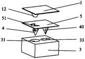
- a microneedle moldwhich is used to manufacture microneedle stickers, includes an upper mold and a lower mold from top to bottom, the upper mold and the lower mold are detachably connected, the upper mold includes an upper mold bottom plate, and at least one inner mold is arranged at the bottom of the upper mold bottom plate mold; the top of the lower mold is provided with at least one first molding cavity, and each first molding cavity corresponds to at least one inner mold setting, and the first molding cavity accommodates the inner mold; the inner mold includes an inner mold body and at least one inner mold body arranged on the inner mold body 1 groove, the groove is used to form a protrusion on the peripheral surface of the first microneedle; the space formed by the first molding cavity and the inner mold is used to shape the first microneedle.
- the inner moldis provided with a guide mouth mold, so that after the first microneedle is formed, a guide mouth is formed on the microneedle with protrusions.
- the guide opening moldis a protrusion arranged on the main body of the inner mold close to the end face of the largest diameter and extending along the circumference, so as to form a guide opening on the first microneedle provided with the protrusion.
- the length of the connecting line at both ends of the open end of the maximum diameter end face of the inner mold body provided with the guide mouth moldis greater than the two guide mouths on the microneedle and the two joints of the outer circumferential side wall of the needle seat on the microneedle with protrusions.
- the length of the junction connection lineis greater than the two guide mouths on the microneedle and the two joints of the outer circumferential side wall of the needle seat on the microneedle with protrusions.
- the direction from the end with the smallest diameter to the end with the largest diameter of the inner mold bodyis the Y direction, and the groove extends along the Y direction.
- the number of groovesis at least two, and along the opposite direction of the Y direction, the volume of the grooves increases sequentially, so that the volume of the corresponding protrusions in the molded microneedles increases sequentially.
- the microneedle moldalso includes a middle plate, the middle plate is located between the upper mold and the lower mold, the middle plate is provided with a middle plate through hole extending up and down, the middle plate through hole accommodates the inner mold, and the middle plate through hole is used to form the base layer, the base The bottom layer and the microneedles form a microneedle patch.
- the top of the lower moldis also provided with at least one second molding cavity.
- the microneedle moldWhen the microneedle mold is closed, there is no inner mold in the second molding cavity; the space in the second molding cavity is used for molding the second microneedle without protrusions.
- the first molding cavity, the inner mold fitted with the first molding cavity, and the second molding cavityform a microneedle mold unit.
- the microneedle mold unitis used to form the microneedle unit.
- the second molding cavityis located at the first One side of the inner mold fitted with a molding cavity is provided with a groove.
- At least one upper mold bottom plate through holeis arranged on the upper mold bottom plate, and each upper mold bottom plate through hole is arranged adjacent to the corresponding inner mold, and is arranged on the same side as the groove on the inner mold; when the inner mold is located in the first molding cavity , along the direction in which the lower mold extends to the upper mold, the space formed by the first molding cavity and the inner mold extends linearly and penetrates through the bottom plate of the upper mold to form a through hole in the bottom plate of the upper mold.
- the radius of the first forming cavityis R 1
- the radius of the second forming cavityis r 1
- 0.17R 1 ⁇ r 1 ⁇ 0.59R 1is 0.17R 1 ⁇ r 1 ⁇ 0.59R 1 .
- the distance from the center of the first molding cavity of the microneedle mold unit to the center of the first molding cavity of the adjacent microneedle unitis L 1 , 3R 1 ⁇ L 1 ⁇ 6R 1 .
- a preparation method of a microneedle patchis prepared by a microneedle mold, and the preparation method comprises the following steps:
- the configuration liquidinto the microneedle forming cavity formed by the upper mold and the lower mold; dry at 4-30°C and 20%-60% humidity for 1-3h to dry and form the microneedle; wherein, the microneedle forming cavity At least a first molding cavity is included, the first molding cavity accommodates an inner mold on the upper mold, and the inner mold is used for molding protrusions on the first microneedles.
- injecting the configuration liquid into the microneedle forming cavity formed by the upper mold and the lower moldincludes the following steps:
- step S2also includes: setting the middle plate between the upper mold and the lower mold, and the middle plate through hole on the middle plate accommodates the inner mold, injects the configuration liquid into the middle plate through hole, and the middle plate through hole
- the configuration liquidis dried to form the base layer; the configuration liquid in the space formed by the first molding cavity and the inner mold is dried and formed with raised microneedles; the dried microneedles with protrusions are pulled out of the first molding cavity;
- the base layeris lifted from the side where the protrusions are not provided on the microneedles to the side where the protrusions are provided on the microneedles, so that the microneedles with protrusions It is separated from the first molding cavity to form a microneedle patch.
- step S2also includes: drying and forming the microneedles with protrusions; pulling out the dried microneedles with protrusions from the first molding cavity; pulling out the microneedles with protrusions from the first molding cavity At the same time, stick the viscous base layer on the top of the lower mold, so that the viscous base layer sticks to the end of the microneedle away from the needle tip, and set the protrusion along the side of the microneedle that is not provided with the protrusion. Lifting the viscous base layer from the raised side to separate the raised microneedles from the first molding cavity to form a microneedle patch.
- the microneedle patch of the present inventionincludes a base layer and a microneedle arranged on the base layer.
- the protrusionextends from the needle tip to the direction of the base layer along the radial direction of the microneedle, so as to After the microneedle punctures and enters the skin, the microneedle is anchored in the skin through the protrusion, which increases the gripping force between the microneedle and the skin, prevents the microneedle from being pushed away from the skin due to elastic deformation of the skin, and achieves continuous and precise drug delivery , and guarantee the effect of administration.
- the protrusions and/or needle points on the microneedles protruding from the needle baseare embedded in the skin, which enhances the adhesion between the microneedles and the skin, so that the microneedles can be punctured immediately after being inserted into the skin. Tear off the base layer to improve the comfort and aesthetics of the microneedle patch, especially when children, pets, and mentally ill patients scratch or lick the base layer during medication, so as to avoid the microneedle from falling off.
- the gripping force between the microneedles and the skinis increased, which can ensure that the microneedles do not move along with the base layer and detach from the skin when the base layer is removed.
- the microneedle patchWhen using the microneedle patch, after the microneedle is inserted into the skin, hold the base layer with your hand, and lift up the base layer along the direction from the side where the microneedle is provided with the fixing part to the side where the fixing part is not provided. Since the junction of the microneedle and the base layer is provided with a stress point structure for tearing and separating the microneedle and the base layer, there is a large stress concentration phenomenon at the stress point structure. When the base layer is torn off, the base layer at the stress point structure will The critical stress for breaking and separating the microneedles is relatively small, so the base layer can be separated from the microneedles under the action of a small external force to tear off the base layer.
- the microneedle mold of the present inventionincludes an upper mold and a lower mold sequentially from top to bottom, the upper mold and the lower mold are detachably connected, the upper mold includes an upper mold bottom plate, and at least one inner mold is arranged at the bottom of the upper mold bottom plate. At least one first molding cavity is arranged on the top of the lower mold, and each first molding cavity is provided corresponding to at least one inner mold, and the first molding cavity accommodates the inner mold. Grooves are arranged on the inner mold to form protrusions on the peripheral surface of the microneedles. The space formed by the first molding cavity and the inner mold is used for molding microneedles. After the microneedles are formed, the upper mold and the lower mold are separated first, and then the microneedles are taken out from the first molding cavity, so as to avoid damage to the protrusions on the microneedles during demoulding.
- Fig. 1is the schematic diagram of microneedle patch of the present invention
- Fig. 2is the schematic diagram that the main body of the microneedle in the microneedle patch of the present invention is a fan-shaped microneedle in horizontal projection;
- Fig. 3is the extended schematic diagram of tearing off the crack when the microneedle paste of the present invention is torn off the base layer;
- Fig. 4is the front view of Fig. 2;
- Fig. 5is the top view of Fig. 2;
- Figure 6is a diagram of the dissolved state after the microneedle is inserted into the skin
- FIG. 7is a schematic diagram of a microneedle in which the main body of the microneedle is a triangular pyramid in the microneedle patch of the present invention
- Fig. 8is the front view of Fig. 7;
- Fig. 9is a schematic diagram of the microneedle body in the microneedle patch of the present invention as a combination of a cone and a cylinder (four protrusions are arranged on the microneedle body, and two protrusions are arranged opposite to each other along the circumferential side wall of the microneedle body) ;
- Figure 10is a top view of Figure 9;
- Figure 11is a schematic diagram of a microneedle body in the microneedle patch of the present invention as a combination of a cone and a cylinder (8 protrusions are arranged on the microneedle body, and two protrusions are symmetrically arranged along the circumferential side wall of the microneedle body) ;
- Fig. 12is a schematic diagram of another viewing angle of Fig. 11;
- Fig. 13is a schematic diagram of another viewing angle of Fig. 11;
- Figure 14is a top view of Figure 11;
- Fig. 15is the front view of Fig. 11;
- Fig. 16is a microneedle schematic diagram in which the main body of the microneedle is a quadrangular pyramid in the microneedle patch of the present invention
- Fig. 17is the front view of Fig. 16;
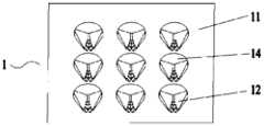
- Figure 18is a schematic diagram of setting a microneedle unit on the base layer
- Fig. 19is the front view of Fig. 18;
- Fig. 20is a schematic diagram of the tearing crack extension of the microneedle sticking of the present invention when the base layer is torn off (the microneedle units are arranged at intervals in multiple rows and rows);
- Fig. 21is a schematic diagram of the tearing crack extension of the microneedle sticking of the present invention when the base layer is torn off (the microneedle units are arranged at intervals);
- Figure 22is a schematic diagram of a microneedle patch with a guide port arranged on the base layer
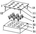
- Fig. 23is an exploded view of the microneedle mold and the formed microneedle patch of the present invention.
- Fig. 24is a schematic diagram of an internal mold for forming a microneedle whose horizontal projection of the needle base and the microneedle main body is fan-shaped;
- Fig. 25is a sectional view of the inner mold of the microneedle for forming the needle seat and the horizontal projection of the microneedle main body in a fan-shaped shape;
- Fig. 26is a schematic diagram of a microneedle mold comprising an upper mold with a through hole on the bottom plate of the upper mold and a microneedle formed by the microneedle mold;
- Fig. 27is a schematic diagram of an upper die provided with a through hole in the upper die bottom plate
- Fig. 28is an exploded view of a microneedle whose main body is a triangular pyramid and a microneedle mold for forming the microneedle in the present invention
- Figure 29is a schematic diagram of the inner mold in Figure 28;
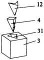
- Fig. 30is an exploded view of a microneedle whose main body is a quadrangular pyramid and a microneedle mold for forming the microneedle in the present invention
- Figure 31is a schematic diagram of the internal mold in Figure 30;
- Figure 32is an exploded view of the microneedle in Figure 9 and the microneedle mold used to shape the microneedle;
- Figure 33is a sectional view of the inner mold in Figure 32;
- Figure 34is a schematic diagram of the internal mold in the microneedle mold for forming the microneedle in Figure 11;
- Figure 35is a schematic diagram of the microneedle and the internal mold fitting in which the horizontal projection of the needle seat and the microneedle main body is fan-shaped;
- Figure 36is an exploded view of a microneedle patch with a microneedle unit arranged on the base layer and a microneedle mold for forming the microneedle patch;
- Fig. 37is the dimensional indication figure of the inner mold in Fig. 25;
- Fig. 38is the experimental data of the penetration force and pull-out force of the first microneedle piercing into the skin in the embodiment with different first protrusions, second protrusions and third protrusions and the comparative example.
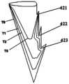
- T0the state when the first microneedle just pierced into the skin
- the side of the first microneedle with protrusionsis facing the side without protrusions, or the side of the first microneedle with protrusions extends toward the second microneedle in the same microneedle unit direction.
- the prior artincludes the following two methods:
- the first methodis: the base layer is an adhesive tape to ensure that after the microneedles are inserted into the skin, the base layer can remain adhered to the skin surface, so as to achieve continuous force on the microneedles, and tear off the base layer after the microneedles dissolve .
- the base layeris an adhesive tape to ensure that after the microneedles are inserted into the skin, the base layer can remain adhered to the skin surface, so as to achieve continuous force on the microneedles, and tear off the base layer after the microneedles dissolve .
- people who are allergic to adhesivescannot use this type of microneedle patch, and children or other special patients, pets, etc. cannot achieve the drug delivery effect of microneedles due to the peeling off of the base layer due to scratching.
- the second methodis: through formula control, the root of the microneedle connecting the microneedle and the base is provided with an easy-to-break layer that is easy to dissolve relative to the drug-containing ingredients.
- the dissolution rate of the water-soluble microneedle material in the skinis also extremely slow, and the dissolution time of the easy fracture is relatively long. Therefore, the practical feasibility of making the base layer easy to tear after dissolution by the microneedle is limited.
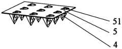
- This embodimentprovides a microneedle patch, which includes a base layer 5 and at least one microneedle, and at least one microneedle is arranged on the bottom of the base layer 5 .
- the microneedlesthemselves carry the drug ingredients and dissolve in the skin.
- the microneedleincludes a first microneedle 4
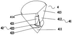
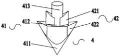
- the first microneedle 4includes a microneedle body 41 .
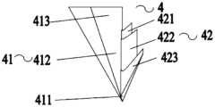
- the microneedle body 41sequentially includes a needle tip 411 , a middle portion 412 and a needle seat 413 .
- the needle base 413is connected to the base layer 5 .
- the circumferential direction of the microneedle body 41is provided with a fixed portion with a non-smooth surface, and the fixed portion includes the portion of the protrusion 42 and/or the needle point 411 that protrudes from the needle seat 413 in the circumferential direction, or is arranged on the microneedle body 41 and when the microneedle sticks Any form of protrusion that can be anchored in the skin after entering the skin.
- at least one protrusion 42is provided in the circumferential direction of the middle portion 412 .
- the microneedle main body 41 and the protrusion 42are integrally formed by a mold, of course, they can also be prepared by 3D printing, centrifugation, pulling and other methods.
- the protrusion 42is pyramid-shaped, the protrusion 42 extends radially along the microneedle body 41 , and has a tip far away from the microneedle body 41 .
- the first microneedle 4has the following advantages:
- the first microneedle 4punctures and enters the skin, the first microneedle 4 is anchored in the skin through the protrusion 42 and/or the part of the needle point 411 protruding from the needle seat 413, which increases the grip between the first microneedle 4 and the skin force to prevent the first microneedle 4 from being pushed away from the skin due to elastic deformation of the skin, to achieve continuous and precise drug delivery, and to ensure the drug delivery effect.
- the protrusion 42 on the first microneedle 4 and the needle point 411 protruding from the needle base 413are embedded in the skin to enhance the gripping force between the first microneedle 4 and the skin.
- the first microneedle 4after the first microneedle 4 is pierced into the skin, when an external force is applied to tear and remove the base layer 5, the first microneedle 4 can still be embedded in the skin and avoid being dragged out of the skin, so that the microneedle patch can be immediately torn off
- the base layer 5improves the comfort and aesthetics of the microneedle patch, especially when children, pets, and mentally ill patients scratch or lick the base layer 5 during medication, so as to prevent the first microneedle 4 from falling off.
- a protrusion 42is provided in the middle part 412 of the microneedle body 41, since the protrusion 42 is located in the middle part of the microneedle body 41 412, which can avoid the weak area of the needle tip 411 on the microneedle main body 41, ensure the strength of the first microneedle 4, and prevent the failure of the first microneedle 4 caused by the fracture of the needle tip 411 due to insufficient strength when the first microneedle 4 penetrates into the skin.
- the protrusion 42is arranged at the middle part 412 of the microneedle main body 41 to form a channel when the needle tip 411 penetrates and enters the skin. Since there are no other structures on the needle tip 411, the penetration resistance is small and the skin recovers from deformation. It has a certain hysteresis, so it can guide the first microneedle 4 and the protrusion 42 to enter the skin smoothly, avoiding or reducing the occurrence or probability of the protrusion 42 breaking during the process of puncturing and entering the skin, thereby ensuring After the first microneedle 4 completely enters the skin, the first microneedle 4 can be stably embedded in the skin due to the elasticity of the skin and the characteristic of recovery after deformation.
- the protrusion 42extends from the needle tip 411 to the direction of the base layer 5 at the middle part 412, so that the protrusion 42 forms a barb-like structure, and the first microneedle 4 can be stably anchored in the skin, thereby increasing the size of the first microneedle. 4 Grip with the skin.
- the angle ⁇ between the extension direction of the protrusion 42 and the axis of the microneedle body 41is preferably 15° ⁇ 75°, more preferably 30° ° ⁇ 60°, so that after the first microneedle 4 is inserted into the skin, the protrusion 42 can be effectively inserted into the skin for the second time, so that the skin is anchored between the microneedle main body 41 and the protrusion 42, and the skin is strengthened.
- the gripping force between the first microneedle 4 and the skinthereby increasing the resistance between the first microneedle 4 and the skin, ensuring that the fitting resistance (grip force) between the first microneedle 4 and the skin is greater than that of the base layer 5 and the skin.
- the peeling force of the first microneedle 4 fracture separationprevents the first microneedle 4 from being dragged out by the base layer 5 when the base layer 5 is torn off and detached from the skin; or, after the microneedle patch adheres to the skin, due to excessive skin secretions
- the microneedle 4is squeezed out by the skin, or when the base layer is a non-adhesive base layer, the microneedle 4 is squeezed into the skin and then squeezed out by the skin. So as to meet the microneedle 4 usage needs of people who are allergic to the viscous basal layer.
- the included angle ⁇ >75°the resistance of the first microneedle 4 into the skin is large, and the needle is easy to break, and when the first microneedle 4 is inserted into the skin, because the skin has elasticity and rigidity at the same time, the first microneedle 4. It cannot fit well with the skin, and the skin is easy to slip out from between the microneedle body 41 and the protrusion 42.
- the secondary insertion effect of the protrusion 42 in the skinis poor, and the anchoring of the first microneedle 4 in the skin poor effect.
- the microneedle main body 41can be in various shapes, including a cone with a fan-shaped horizontal projection, a pyramid with an elliptical fan-shaped horizontal projection, a triangular pyramid, a quadrangular pyramid, and other shapes.
- the specific arrangement of the protrusion 42 on the microneedle body 41 of several shapesis as follows:
- the protrusion 42is located on the microneedle main body 41 and connected On the edge of the fan-shaped plane tip, on the one hand, the resistance when the first microneedle 4 is pierced into the skin is reduced; The deformation of the skin in the contact area is small, and the skin and the protrusion 42 on the first microneedle 4 can fit together relatively well, thereby promoting the anchoring effect between the protrusion 42 and the skin.
- the number of protrusions 42is at least one, preferably 2-3, and the protrusions 42 are arranged along the edges of the microneedle main body 41 connecting the fan-shaped flat tip in turn. . If only one protrusion 42 is provided, as the first microneedle 4 penetrates into the skin, the protrusion 42 dissolves, and the stable skin gripping force between the first microneedle 4 and the skin cannot be continuously maintained, and the first microneedle 4 easily pushed out by the skin.
- the horizontal projected area and volume of the plurality of protrusions 42increase sequentially, so as to increase and continuously realize the first microneedle. Gripping force between the microneedle 4 and the skin.
- the protrusions 42include a first protrusion 421 and a second protrusion 422 in sequence.
- the shape of the protrusion 42is set so as not to affect the demoulding. Specifically:
- the circumferential sidewall of the first protrusion 421extends vertically, or is inclined toward the direction close to the microneedle body 41, and the circumferential sidewall of the second protrusion 422 extends vertically, or abuts against the periphery of the molding cavity of the mold. Towards the side wall, so as to prevent the first protrusion 421 from affecting the demoulding of the second protrusion 422 .
- the protrusions 42include the first protrusion 421, the second protrusion 422 and other protrusions 42, the third protrusion in turn. from 423.
- the shape of the protrusion 42is set so as not to affect the demoulding. Specifically:
- the circumferential sidewall of the first protrusion 421extends vertically.
- the peripheral sidewalls of the second protrusion 422 and other protrusions 42 located between the first protrusion 421 and the third protrusion 423extend vertically, or are arranged obliquely towards the direction close to the microneedle body 41 .
- the peripheral sidewall of the third protrusion 423extends vertically, or abuts against the peripheral sidewall of the molding cavity of the mould.
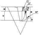
- the protrusion 42sequentially includes a first protrusion 421, a second protrusion 422 and a third protrusion 423, and the first protrusion 421, the second protrusion 422 and the The horizontal projected area and volume of the third protrusion 423 increase sequentially.
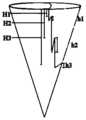
- the vertical distance H1 between the tip of the first protrusion 421 and the base layer 5is 100 ⁇ m to 130 ⁇ m, and the height h1 from the base of the first protrusion 421 to the tip is 30 ⁇ m;
- the vertical distance H2 between the 5is 250 ⁇ m to 350 ⁇ m, the height h2 from the base of the second protrusion 422 to the tip is 100 ⁇ m;
- the vertical distance H3 between the tip of the third protrusion 423 and the base layer 5is 250 mm to 450 mm, from The height h3 from the base of the third protrusion 423 to the tip is 50 ⁇ m.
- the included angle between the extension direction of the first protrusion 421 and the axis of the microneedle body 41is 45°, and the extension direction of the second protrusion 422 and the microneedle axis
- the included angle between the axes of the needle main body 41is 30°, and the included angle between the extending direction of the third protrusion 423 and the axis of the microneedle main body 41 (the vertical line passing through the needle tip 411) is 60° .
- the angle between the extending direction of the third protrusion 423 and the axis of the microneedle body 41is 60°, and the height h3 from the base to the tip is 50 ⁇ m.
- the angle between the extending direction of the second protrusion 422 and the axis of the microneedle main body 41is 30°, the height h2 from the base to the tip is 100 ⁇ m, the gap between the skin and the skin is relatively small, and the fit is relatively good.
- the second protrusion 422is easy to be inserted into the skin twice, and strengthens the resistance between the first microneedle 4 and the skin, so that the first microneedle 4 can stay in the skin, and when the first microneedle 4 is inserted into the skin and the skin recovers After the deformation, the gap between the skin and the third protrusion 423 and the first protrusion 421 on the first microneedle 4 is relatively reduced, and the degree of fit is better, and the second penetration into the skin can be better realized, so that the first microneedle 4 The microneedles 4 are stably embedded in the skin.
- the dissolution rateis relatively slow, so the volume of the first protrusion 421 should not be too large.
- Fig. 38is the experimental data of the penetration force and pull-out force of the first microneedle 4 piercing the skin in the embodiment and the comparative embodiment where the first protrusion 421, the second protrusion 422 and the third protrusion 423 are different.
- the crushing force of the first microneedle 4 of the present inventionthat is, the maximum resistance value that the first microneedle 4 can withstand when piercing the skin is ⁇ 0.1N, and the first microneedle 4 can penetrate the skin completely and smoothly.
- the pull-out force after the first microneedle 4 is pierced into the skinis the gripping force between the first microneedle 4 and the skin after being pierced into the skin ⁇ 0.06N, and the tearing and separation force of the base layer 5 and the first microneedle 4 ⁇ 0.06N, to ensure that the first microneedles 4 can be stably embedded in the skin when the base layer 5 is torn off after the first microneedles 4 are pierced into the skin.
- the first protrusion 421is located in the stratum corneum, and it is generally believed that the skin moisture content near the stratum corneum is low, so The dissolution speed of the first protrusion 421 fitted here is relatively slow, and the first protrusion 421 can provide skin gripping force for a longer period of time even though its volume is the smallest.
- the second protrusion 422 and the third protrusion 423are all embedded below the stratum corneum, where the skin moisture content is higher, and the dissolution rate of the second protrusion 422 and the third protrusion 423 is faster, because the second protrusion
- the volume of the third protrusion 422is smaller than that of the third protrusion 423 , therefore, the dissolution time of the third protrusion 423 is longer than that of the second protrusion 422 .
- the skinhas the strongest rebound force, and the second protrusion 422 and the third protrusion 423 can provide stronger skin gripping force to counteract the skin rebound force, so that the first microneedle The needle 4 is stably fitted in the skin.
- the microneedle main body 41, the second protrusion 422 and the third protrusion 423dissolve, and the gripping force of the first microneedle 4 on the skin weakens. At this time, the deformation of the skin decreases and the rebound force weakens. .
- the third protrusion 423can still play a certain gripping force without completely dissolving, and the degree of dissolution of the first protrusion 421 is small, the first protrusion 421 and the third protrusion 423 It can still provide sufficient skin gripping force to ensure that the first microneedles 4 are stably embedded in the skin and avoid being pushed out by the skin.
- the microneedle main body 41is a cone shaped as an elliptical fan in horizontal projection: the protrusion 42 is located on the edge of the microneedle main body 41 connecting the tip of the elliptical fan-shaped bottom surface, and is located at the level of the microneedle main body 41 The minor axis side of the projection.
- the volume of the first microneedle 4 in this embodimentis increased to increase the drug loading capacity of the first microneedle 4 to meet the dosage form requirements of different medicines.
- the difference between this embodiment and Embodiment 1is that the microneedle body 41 is a triangular pyramid: the protrusion 42 is located on the edge of the microneedle body 41 to reduce the penetration of the first microneedle 4 into the skin time resistance.
- the protrusion 42is located on the edge perpendicular to the base layer 5 to further reduce the resistance when the first microneedle 4 penetrates the skin.
- the difference between this embodiment and Embodiment 1is that the microneedle body 41 is a quadrangular pyramid: the protrusion 42 is located on the edge of the microneedle body 41 to reduce the penetration of the first microneedle 4 into the skin time resistance.
- the protrusion 42is located on the edge perpendicular to the base layer 5 to further reduce the resistance when the first microneedle 4 penetrates the skin.
- the difference between this embodiment and Embodiment 1is that the microneedle body 41 is a combination of a cone and a cylinder, the tip 411 of the microneedle body 41 is a cone, and the middle part 412 and the needle seat 413 are cylinders .
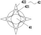
- the number of protrusions 42 of the first microneedle 4is four, and preferably, two protrusions 42 are arranged opposite to each other along the circumferential sidewall of the middle part 412 of the microneedle body 41 .
- the protrusions 42 arranged on the peripheral side wall of the middle part 412 of the microneedle body 41are symmetrically arranged, and are respectively the first protrusion 421 and the second protrusion 422, along the needle seat 413 of the first microneedle 4 toward the needle tip. 411 direction, the horizontal projected area and volume of the first protrusion 421 are smaller than the second protrusion 422 .
- the vertical distance H1 between the tip of the first protrusion 421 and the base layeris 50 ⁇ m, and the height h1 from the base of the first protrusion 421 to the tip is 50 ⁇ m; the vertical distance between the tip of the second protrusion 422 and the base layer The distance H2 is 200 ⁇ m, and the height h2 from the base of the second protrusion 422 to the tip is 30 ⁇ m.
- the angle ⁇ 1 between the extension direction of the first protrusion 421 and the axis of the microneedle body 41(that is, the vertical line passing through the needle tip 411) is 45°, and the angle ⁇ 1 between the extension direction of the second protrusion 422 and the axis of the microneedle body 41 The angle ⁇ 2 is 75°. Because the middle part 412 of the microneedle main body 41 of this embodiment is symmetrically provided with the first protrusion 421 and the second protrusion 422 on the circumferential side wall, the first microneedle 4 is stuck in the skin after the first microneedle 4 is inserted into the skin.
- the microneedle 4pierces the stratum corneum under the action of external force, and when the skin deformation recovers, the secondary insertion effect of the protrusion 42 in the skin is good.
- the first microneedle 4has a strong anchoring effect and can be stably embedded in the skin.
- One microneedle 4can be made relatively short to prevent the first microneedle 4 from piercing into the dermis and realize painless administration.
- the first microneedle 4is a combination of a cone and a cylinder, the structure close to the needle seat 413 is a cylinder with a small volume.
- the first microneedle 4When the first microneedle 4 is pierced into the skin, it can be immediately The basal layer is torn off so that the main body of the conical part of the first microneedle 4 can be completely embedded in the skin, so that the components of the first microneedle 4 can be effectively absorbed and the drug administered accurately.
- human skinis an anisotropic material, such as human torso skin
- the transverse elasticityis weak and the stress is large, while the longitudinal elasticity is strong and the stress is small.
- the difference between the longitudinal and transverse stress valuescan be nearly doubled.
- the greater stress of the skincan provide support for the insertion of the first microneedle 4 to facilitate the insertion of the first microneedle 4 .
- the first microneedle 4 in the present embodimentis arranged on both sides of the microneedle main body 41 because of the protrusion 42, and the microneedle main body 41 is flat. The direction of the long axis of the trunk or the extension direction of the limbs is pierced into.
- the flat first microneedle 4 in this embodimentcan push the first microneedle 4 under the action of a smaller external force.
- the needle 4is pierced into the skin to reduce the pain of the skin.
- the difference between this embodiment and Embodiment 5is that the microneedle body 41 is a combination of a cone and a cylinder, the tip 411 of the microneedle body 41 is a cone, and the middle part 412 and the needle seat 413 are cylinders , the number of protrusions 42 of the first microneedle 4 is eight.
- four groups of protrusions 42are arranged symmetrically along the circumferential sidewall of the middle part 412 of the microneedle body 41, and each group of protrusions 42 includes two protrusions arranged along the axis of the microneedle body 41 (a vertical line passing through the needle tip 41). Raised 42.
- each grouppreferably along the needle seat 413 of the first microneedle 4 toward the needle tip 411, each group includes two protrusions 42, and the horizontal projected area and volume of the two adjacent protrusions 42 increase, In order to increase and continuously realize the gripping force between the first microneedle 4 and the skin.
- two protrusions 42 arranged in each groupare respectively the first protrusion 421 and the second protrusion 422.
- the seat 413faces the direction of the needle tip 411 , and the horizontal projected area and volume of the first protrusion 421 are smaller than the second protrusion 422 .
- the vertical distance H1 between the tip of the first protrusion 421 and the base layeris 45 ⁇ m, and the height h1 from the base of the first protrusion 421 to the tip is 30 ⁇ m; the vertical distance between the tip of the second protrusion 422 and the base layer
- the distance H2is 100 ⁇ m, and the height h2 from the base of the second protrusion 422 to the tip is 100 ⁇ m.
- the angle ⁇ 1 between the extension direction of the first protrusion 421 and the axis of the microneedle body 41(the vertical line passing through the needle tip 411) is 45°, and the angle between the extension direction of the second protrusion 422 and the axis of the microneedle body 41 ⁇ 2 is 75°.
- the four groups of protrusions 42 arranged symmetrically on the side wall of the microneedle main body 41 in this embodimentinclude the first protrusion 421 and the second protrusion 422 respectively, after the first microneedle 4 is inserted into the skin, due to the large elasticity of the skin , the first microneedle 4 is pressed into the skin and pierces the stratum corneum under the action of external force, and the skin deformation recovers after the external force is released, but since the first microneedle 4 has 4 groups of 8 in total arranged along the microneedle body 41 circumferential direction Protrusion 42, the secondary insertion effect of protrusion 42 in the skin is better, the anchoring effect of the first microneedle 4 is stronger, and can be stably fitted in the skin, so the first microneedle 4 can be made shorter to avoid The first microneedle 4 is pierced into the dermis to realize painless administration, and is more suitable for children, pets and other people who are easy to break free.
- the structure close to the needle seat 413is a cylinder with a small volume.
- the base layercan be torn off immediately to The main body of the conical part of the first microneedle 4 is completely embedded in the skin, and the components of the first microneedle 4 are effectively absorbed and the drug is administered precisely.
- the difference between this embodiment and Embodiment 1is that the microneedles are attached to the junction of the base layer 5 and the first microneedles 4 to provide a stress point structure.
- the stress point structureincludes a base through hole 51 disposed on the same side as the protrusion 42 on the first microneedle 4 on the base layer 5 .
- the maximum length of the base through hole 51is greater than the maximum length of the first microneedle 4, so that when the base layer 5 is torn off, the The cracks can extend around the two sides of the first microneedle 4 and then intersect.
- the base through hole 51is a major arc
- the projection of the first microneedles 4 on the base layer 5is a minor arc.
- the base layer 5is grasped by hand, and the protrusion 42 is provided along the side of the first microneedle 4 without the protrusion 42 Lift the base layer 5 in one side direction.
- a protrusion 42is provided toward the first microneedle 4 along the side where the first microneedle 4 is not provided with the protrusion 42
- One sideis demolded, and the microneedle sticker is separated from the mold to ensure that the first microneedle 4 is intact.
- the first microneedle 4In the process of tearing off the base layer 5, because the protrusion 42 is provided on the first microneedle 4, the first microneedle 4 is grasped in the skin through the protrusion 42, which satisfies the fit between the first microneedle 4 and the skin
- the base layer 5can be completely separated from the first microneedle 4 , which improves the tearability of the base layer 5 .
- the base layer 5can be torn off immediately after the first microneedle 4 is inserted into the skin, and only the first microneedle 4 remains in the skin, thereby improving the comfort and aesthetics of the microneedle patch, and avoiding children, Pets and mentally ill patients scratch or lick the basal layer 5 during medication, which causes the first microneedle 4 to fall off.
- the difference between this embodiment and embodiment 1is that the microneedles are attached to the connection between the base layer 5 and the first microneedles 4 to set a stress point structure.
- the stress point structureincludes a substrate through-hole 51 disposed on the base layer 5 and a guide port 414 disposed on the needle seat 413 of the first microneedle 4 .
- the guide port 414is located at the junction of both sides of the needle seat 413 of the microneedle and the base through hole 51 , and the guide port 414 is located on the circumferential side wall of the needle seat 413 .
- the first microneedle 4 and its adjacent base through hole 51form a group of stress units, and at least one group of stress units are arranged at intervals on the base layer 5.
- the tearing external forceacts on the base layer 5 and is transmitted to the guide opening 414 through the base layer 5 .
- the guide port 414reduces the critical separation force between the base layer 5 and the needle base 413 of the first microneedle 4, and when the base layer 5 is torn off when the microneedle is applied, the guide port 414 can guide the base layer 5 and the first microneedle 4.
- the tear-off crack between the microneedles 4extends along the crack 6 . Since the protrusion 42 provided on the first microneedle 4 makes the first microneedle 4 stably fit in the skin, in the process of tearing off the base layer 5, the external force and the fitting force between the first microneedle 4 and the skin Under the action of the combined force, the crack 6 generated between the base layer 5 and the first microneedle 4 can accurately extend from the guide port 414 along the circumferential side wall of the needle seat 413 of the first microneedle 4, and in the adjacent two groups The intersections between the stress units on the base layer 5 form a meeting point 60 , so that the first microneedles 4 are completely separated from the base layer 5 .
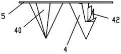
- the microneedle patchincludes at least one microneedle unit, and each microneedle unit includes at least one first microneedle 4 and second microneedle 40 arranged at intervals, as shown in Figures 18-21 shown.
- the first microneedle 4is a microneedle with protrusions 42
- the second microneedle 40is a microneedle without protrusions 42 .
- the second microneedle 40 without the protrusion 42can increase the drug loading of the microneedle patch, and the first microneedle 4 with the protrusion 42 can increase the gripping force with the skin , to meet the needs of microneedle patches with large drug loading and stable grip on the skin.
- the second microneedle 40is located on the side of the first microneedle 4 without the protrusion 42, and the minimum length of the line connecting the guide ports 414 on both sides of the first microneedle 4 is greater than that of the second microneedle 4.
- the guide port 414is located on the circumferential side wall of the needle seat 413 of the first microneedle 4, and the extension line of the guide port 414 on both sides of the first microneedle 4 is aligned with the circumferential side wall of the needle seat 413 of the second microneedle 40. intersect or tangent.
- the extension lines of the guide openings 414 on both sides of the first microneedle 4are tangent to the circumferential sidewall of the seat 413 of the second microneedle 40 .
- the microneedle main body 41is set to be horizontally projected into a fan shape, the junction point between the guide ports 414 on both sides of the needle holder 413 and the needle holder 413 is A, and the distance between the two junction points A and the center line of the first microneedle 4 is respectively The included angle is 120°-150°, the radius of the first microneedle 4 is R, and the radius of the second microneedle 40 is r, then 0.17R ⁇ r ⁇ 0.59R.
- the multiple microneedle unitsare arranged on the base layer 5 at intervals in multiple rows and columns, and the protrusions 42 of the first microneedle 4 extend in the same direction, as shown in the figure 20 shown.
- the base layer 5is torn off along the side where the first microneedle 4 is provided with the protrusion 42 to the direction in which the second microneedle 40 is provided in the same microneedle unit, that is, the X direction, and the crack 6 is along the The extending direction of the joint point A extends, meets at the gap with the adjacent microneedle unit, and forms a meeting point 60 .
- the distance from the center of the first microneedle 4 of the microneedle unit to the center of the first microneedle 4 of the adjacent microneedle unitis L, 3R ⁇ L ⁇ 6R, so as to ensure that the intersection point 60 formed by the crack 6 is located between the two microneedle units, the base layer 5 can be effectively torn off, and the microneedle unit is stably embedded in the skin without being dragged by the base layer 5 and leaving the skin. To achieve effective and precise drug delivery.
- the base layer 5has sufficient strength.
- the strength of the needle-free area of the base layer 5(that is, the area where no microneedles are set) It is enough to tear off the base layer 5 at one time, which can effectively avoid the need to tear off the base layer 5 multiple times due to the breakage of the needle-free area of the base layer 5 .
- the injection amount of the raw material solution of the base layer 5is controlled, so that the thickness of the base layer 5 at the junction with the needle seat 413 is smaller than that of the base layer in the needle-free region due to the shrinkage of the raw material liquid after the second microneedle 40 is dried.
- the second microneedle 40is not provided with a protrusion 42, because the first microneedle 4 is provided with a protrusion 42, the first microneedle 40
- the microneedle 4fits stably with the skin, and the crack 6 generated when the base layer 5 is torn off surrounds the microneedle unit and meets at the gap between the adjacent microneedle units, so that the second microneedle 40 can be stably fitted into the skin.
- the base layer 5can be separated along the circumferential side wall of the second microneedle 40, and finally realizes that the microneedle unit is stably embedded in the skin Medium, effective and precise drug delivery.
- the grip force between the first microneedle 4 or the microneedle unit and the skinis improved by the protrusion 42 on the first microneedle 4, so as to avoid microneedle sticking.
- the base layer 5is torn off immediately after being attached to the skin, the first microneedles 4 or the second microneedles 40 are taken out by the base layer 5, which greatly shortens the time required for the base layer 5 to be attached to the skin when the microneedle patch is used. It takes time, and then improves the use comfort of the microneedle patch, which is convenient for children who are sensitive to the base layer 5 or use it.
- Embodiment 9The difference between this embodiment and Embodiment 9 is that the microneedle units are arranged at random intervals, as shown in FIG. 21 , increasing the density of microneedle units in the microneedle patch and increasing the amount of drug loaded in the microneedle patch.
- the difference between this embodiment and Embodiment 1is that the microneedle is attached to the connection between the base layer 5 and the first microneedle 4 to set a stress point structure.
- the stress point structureincludes a substrate through hole 51 disposed on the base layer 5 and a guide port 414 disposed at the junction of the base 413 of the first microneedle 4 and the base layer 5 , and the guide port 414 is located on the base layer 5 .
- the first incision line 4141 and the second incision line 4142 communicating with the substrate through hole 51are set on the base layer 5 near the junction of the base through hole 51 and the needle seat 413, the base through hole 51, the first incision line 4141
- the base area surrounded by the second cutting line 4142forms the guide opening 414 .
- One end of the first incision line 4141communicates with the base through hole 51 , and the other end communicates with the second incision line 4142 .
- the second incision line 4142forms a certain angle with the first incision line 4141, so that the extension lines of the second incision line 4142 on both sides of the needle base 413 can intersect at the base layer between the stress unit and the adjacent stress unit 5 on.
- the tearing external forceacts on the base layer 5 and is transmitted to the guide port 414 through the base layer 5 .
- the guide port 414reduces the critical separation force between the base layer 5 and the needle base 413 of the first microneedle 4, and when the base layer 5 is torn off when the microneedle is applied, the guide port 414 can guide the base layer 5 and the first microneedle 4.
- the tearing cracks between the microneedles 4extend along the second cutting line 4142 and meet at the base layer between two adjacent stress units.
- this embodimentalso provides a microneedle mold for manufacturing the above-mentioned microneedle patch.
- the microneedle mold of this embodimentincludes an upper mold 1 and a lower mold 3 from top to bottom, and the upper mold 1 and the lower mold 3 are detachably connected.
- the upper mold 1includes an upper mold bottom plate 11 , and at least one inner mold 12 is arranged on the bottom of the upper mold bottom plate 11 .
- At least one groove 122is provided on the inner mold 12 to form at least one protrusion 42 on the middle part 412 of the first microneedle 4 .
- the molded first microneedle 4 with a non-smooth surfacecan be easily taken out of the microneedle mold.
- the protrusion 42can be formed on the microneedle, thereby improving the gripping force of the microneedle on the skin during use.
- At least one first molding cavity 31is arranged on the top of the lower mold 3 .
- Each first molding cavity 31is provided corresponding to at least one inner mold 12 , and the first molding cavity 31 accommodates the inner mold 12 .
- the space formed by the first forming cavity 31 and the inner mold 12is used for forming the first microneedle 4 .
- At least one protrusion 42is formed on the middle part 412 of the first microneedle 4.
- the upper mold 1 and the lower mold 3are separated first, and then the second microneedle 4 is separated.
- a microneedle 4is taken out from the first molding cavity 31 to prevent the protrusion 42 on the first microneedle 4 or the part of the needle point 411 protruding from the middle part 412 from being damaged during the demoulding process.
- the inner mold 12includes an inner membrane main body 120 , a groove 122 provided on the inner mold main body 120 and a guide mouth mold 123 .
- the guide mouth mold 123is a protrusion disposed on the end face of the inner mold main body 120 with the largest diameter and extending along the circumferential direction.
- the inner mold main body 120is provided with the length of the connection line at the two ends of the open end of the largest diameter end surface of the guide mouth mold 123 greater than the length of the connection line between the two guide ports 414 on the first microneedle 4 and the junction point of the outer peripheral side wall of the needle holder 413. length.
- the end face of the largest diameter of the inner mold main body 120is a superior arc
- the end face of the largest diameter of the first microneedle 4is an inferior arc, so that when the microneedle paste base layer 5 is torn off, the tear crack can surround the two sides of the first microneedle 4. Intersect after side extension.
- the direction from the end with a smaller diameter to the end with a larger diameter of the inner mold main body 120is the Y direction, and the groove 122 extends along the Y direction.
- the angle between the extending direction of the groove 122 and the axis of the inner mold 12is ⁇ , preferably 15° ⁇ 75°, more preferably 30° ⁇ 60°.
- the number of grooves 122is at least one, and along the opposite direction of the Y direction, the volume of the grooves 122 increases sequentially, so that the corresponding protrusions in the formed first microneedles 4
- the volume of 42increases sequentially.
- the number of the grooves 122is at least 2, more preferably 3, namely the first groove 1221 , the second groove 1222 and the third groove 1223 .
- the distance G1 between the bottom of the first groove 1221 and the larger-diameter end surface of the inner mold 12is 100 ⁇ m to 130 ⁇ m, and the vertical extension distance g1 of the first groove 1221 is 30 ⁇ m; the bottom of the second groove 1222 and the inner mold
- the distance G2 between the larger diameter end face of 12is 250 ⁇ m to 350 ⁇ m, the vertical extension distance g2 of the second groove 1222 is 100 ⁇ m;
- the distance G3 between the bottom of the third groove 1223 and the larger diameter end surface of the inner mold 12is 250 mm to 450 mm,
- the vertical extension distance g3 of the third groove 1223is 50 mm.
- the angle ⁇ 1 between the extension direction of the first groove 1221 and the axis of the inner mold 12is 45°
- the angle ⁇ 2 between the extension direction of the second groove 1222 and the axis of the inner mold 12is 30°
- the third groove 1223The included angle ⁇ 3 between the extension direction and the axis of the inner mold 12 is 60°.
- the section of the inner mold main body 120is provided with a groove 122 as a vertical wall with a draft slope, so that the inner mold 12 is pulled out from the first molding cavity 31 when the first microneedle 4 is prepared, and the protrusion is ensured. From 42 intact, to ensure the yield of the product.
- the groove 122includes a first groove 1221 and a second groove 1222: the first groove 1221 is used to form the first protrusion 421 on the first microneedle 4, and the second groove 1222 is used to form the second protrusion 422 to form two protrusions 42 in the Y direction of the first microneedle 4, on this basis, the inner mold main body 120 is formed between the end of the first molding cavity 31 and the first molding cavity 31 The third protrusion 423 forms three protrusions 42 in the Y direction of the first microneedle 4 .
- the groove 122includes a first groove 1221, a second groove 1222 and a third groove 1223: the first groove 1221 is used to form the first protrusion 421 on the first microneedle 4, and the second groove 1222 It is used to form the second protrusion 422 , and the third groove 1223 is used to form the third protrusion 423 to form three protrusions 42 in the Y direction of the first microneedle 4 .
- a fourth protrusioncan also be formed between the end of the inner mold body 120 near the end of the first molding cavity 31 and the first molding cavity 31 .
- the specific structure of the microneedle mold used to form the first microneedle 4 in the shape shown in Figure 2 in Example 1is as follows:
- the first molding cavity 31 of the lower mold 3is conical.
- the first molding cavity 31 of the lower mold 3is a cone with an elliptical horizontal projection.
- the first molding cavity 31 of the lower mold 3is a triangular pyramid.
- the first molding cavity 31 of the lower mold 3is a quadrangular pyramid.
- the horizontal projection of the inner mold 12is a circle or an ellipse.
- the first molding cavity 31 of the lower mold 3is conical.
- the horizontal projection of the inner mold 12is an ellipse
- the first molding cavity 31 of the lower mold 3is in the shape of an ellipse cone.
- the lower mold 3is injection molded from Polydimethylsiloxane, and the thickness of the lower mold 3 is preferably 5000 ⁇ m.
- the first molding cavity 31 of the lower mold 3is treated by Teflon spraying process to prevent the first molding cavity 31 from sticking to the first microneedle 4 so as to facilitate the separation of the first microneedle 4 and the first molding cavity 31 .
- the bottom of the upper mold 1is provided with a positioning plunger 13
- the top of the lower mold 3is provided with a positioning groove 32 corresponding to the positioning plunger 13.
- the pre-positioning between the positioning insert rod 13 of the upper mold 1 and the positioning groove 32 of the lower mold 3is used to ensure that each inner mold 12 of the upper mold 1 corresponds to each first molding cavity of the lower mold 3 31.
- the end of the positioning plunger 13 close to the upper die 1is cylindrical, and the end away from the upper die 1 is conical, so that the positioning plunger 13 can be inserted into the positioning groove 32 .
- the shape of the positioning groove 32is matched with the positioning insertion rod 13 , so that the positioning insertion rod 13 can be precisely and stably engaged with the positioning groove 32 .
- the height of the positioning plunger 13is 600 ⁇ m, and the diameter of the conical end is 300 ⁇ m.
- the four positioning inserts 13 and four positioning slots 32are provided, the four positioning inserts 13 are respectively located at the four ends of the upper mold bottom plate 11, and the four positioning slots 32 are respectively located at the four ends of the lower mold 3 top place, so that the upper mold 1 is stably assembled on the lower mold 3.
- this embodimentalso provides a preparation method for the microneedle patch, including the following two methods:
- the first microneedle 4is formed first, and then prepared into a microneedle patch. Including the following steps:
- A1Combine the upper mold 1 and the lower mold 3, insert the inner mold 12 into the first molding cavity 31, and inject the configuration liquid into the space formed by the first molding cavity 31 and the inner mold 12.
- A2The upper mold 1 and the lower mold 3 are separated, the base layer 5 is attached to the dried and formed first microneedle 4, and the first microneedle 4 is pulled out.
- the integrated molding methodis adopted, that is, the first microneedles 4 and the first base layer 5 are integrally formed into a microneedle patch. Including the following steps:
- B1inject configuration liquid into the first molding cavity 31 , and then combine the upper mold 1 and the lower mold 3 to insert the inner mold 12 into the first molding cavity 31 .
- the drying conditions in steps A2 and B2are: drying at 4-30° C. and 20%-60% humidity for 1-3 hours.
- step B2the dried and formed first microneedle 4 is pulled out along the side where the first microneedle 4 is provided with the protrusion 42 .
- the base layer 5 of the molded microneedle patchforms base through holes 51 corresponding to the positions where the inner mold 12 is provided.
- the microneedle mold provided in this embodimentis used to form the base layer 5 of the complete plate and set at least one microneedle patch composed of the first microneedle 4, the first microneedle 4 is set At least one protrusion 42 .
- the positioning plunger 13 of this embodimentWhen the positioning plunger 13 of this embodiment is inserted into and abuts against the bottom of the positioning groove 32 , there is a gap between the upper mold 1 and the lower mold 3 .
- the gapis used for air circulation to speed up the drying of the configuration liquid in the first molding cavity 31 Shaped into the speed of the first microneedle 4.
- the gap between the upper mold 1 and the lower mold 3is 1-10mm, more preferably, the gap is 5mm.
- this embodimentalso provides a preparation method of a microneedle patch, which adopts a two-step forming microneedle patch, that is, the first microneedle 4 is formed first, and then prepared into a microneedle patch. Specific steps are as follows:
- C2Inject the dispensing liquid into the first molding cavity 31 by high-pressure injection, and scrape the dispensing liquid along the top of the lower mold 3, so that each first molding cavity 31 is filled with the dispensing liquid;
- step C4drying at 4°C and 20% humidity for 1 hour.
- the microneedle mold provided by this embodimentis used to form a microneedle patch composed of a base layer 5 of a complete plate and at least one first microneedle 4, At least one protrusion 42 is provided on the first microneedle 4 .
- the upper mold bottom plate 11 in this embodimentis provided with at least one upper mold bottom plate through hole 14, at least one upper mold bottom plate through hole 14 is arranged at intervals, the upper mold bottom plate through hole 14 and the inner mold 12 are adjacently arranged, and the upper mold bottom plate through hole 14 is arranged on the same side as the groove 122 on the corresponding inner mold 12.
- the space formed by the first molding cavity 31 and at least one inner mold 12extends linearly and runs through the upper mold bottom plate 11 Afterwards, the through hole 14 of the bottom plate of the upper mold is formed.
- the positioning plunger 13 and the positioning groove 32when the positioning plunger 13 is inserted into and abuts against the bottom of the positioning groove 32, the upper mold 1 abuts the lower mold 3, and the configuration liquid in the first molding cavity 31 passes through The through hole 14 of the upper mold base plate is ventilated and dried.
- this embodimentalso provides a preparation method of the microneedle patch, which adopts a two-step forming microneedle patch: that is, the first microneedle 4 is formed first, and then prepared into a microneedle patch.
- the configuration liquidcovers the surface of the microneedle mold and is centrifuged.
- the configuration liquidis injected into the first molding cavity 31 from the through hole 14 of the bottom plate of the upper die 1, and scraped along the top of the upper die 1 with a scraper to make each first
- the molding cavity 31is filled with configuration liquid;
- D6Attach the viscous base layer 5 to the top of the lower mold 3, so that the viscous base layer 5 sticks to the end of the needle seat 413 of the first microneedle 4 away from the end of the needle tip 411, and the first microneedle Lift the base layer 5 from the side of the needle 4 without the protrusion 42 to the side of the first microneedle 4 provided with the protrusion 42 , so as to separate the formed first microneedle 4 from the first molding cavity 31 .
- the drying conditions in step D4are: 1.5 hours at 25° C. and 45% humidity.
- the microneedle mold provided by this embodimentis used to form a microneedle patch composed of a base layer 5 provided with a base through hole 51 and at least one first microneedle 4. , at least one protrusion 42 is provided on the first microneedle 4 .
- the microneedle mold of this embodimentalso includes a middle plate 2, the middle plate 2 is located between the upper mold 1 and the lower mold 3, and the middle plate 2 is detachably connected with the upper mold 1 and the lower mold 3 respectively.
- the middle plate 2is provided with a middle plate through hole 21 , and the middle plate through hole 21 is used for accommodating the inner mold 12 and for forming the base layer 5 with the base through hole 51 .
- a positioning hole 22is provided on the middle plate 2 , and the positioning hole 22 corresponds to the positioning insertion rod 13 and the positioning groove 32 .
- the middle board 2is made of other types of plastics such as PET (polyethylene terephthalate), and the thickness of the middle board 2 is preferably 0.1-2 mm.
- the structures of the positioning plunger 13 of the upper mold 1 and the positioning groove 32 of the lower mold 3 in this embodimentare consistent with those in Embodiment 11.
- this embodimentalso provides a preparation method of the microneedle patch, which adopts a one-step forming microneedle patch, and the specific method is as follows:
- E1Mix sodium hyaluronate and functional materials into a configuration liquid, and defoam
- E3Inject the dispensing liquid into the first molding cavity 31 by high-pressure injection, and scrape it flat along the middle plate 2 with a scraper, so that the dispensing liquid fills the through hole 21 of the middle plate;
- E4Insert the positioning insert rod 13 of the upper mold 1 into the positioning groove 32 of the lower mold 3, and insert at least one inner mold 12 on the upper mold 1 into the first molding cavity 31 on the lower mold 3;
- E6pull the inner mold 12 out of the first molding cavity 31, separate the middle plate 2 and the lower mold 3, and form a base through hole 51 at a position corresponding to the inner mold 12 on the base layer 5;
- E7lift the base layer 5 from the side of the first microneedle 4 where the protrusion 42 is not provided to the side where the first microneedle 4 is provided with the protrusion 42, so as to separate the first microneedle 4 from the first molding cavity 31, Formed into microneedle patches.
- step E5the drying conditions in step E5 are: 4°C, 60% humidity for 3 hours.
- the inner mold 12 of the upper mold 1is first pulled out from the first molding cavity 31 of the lower mold 3. At this time, a base through hole 51 is formed on the base layer 5 of the microneedle patch.
- the first microneedle 4 of the protrusion 42is still located in the first molding cavity 31 , and there is a gap between the side of the microneedle body 41 where the protrusion 42 is disposed and the first molding cavity 31 .
- the base layer 5is uncovered along the direction from the side where the first microneedle 4 is not provided with the protrusion 42 to the side where the protrusion 42 is provided.
- the first microneedles 4are integrally molded on the base layer 5 , therefore, the first microneedles 4 are separated from the first molding cavity 31 together with the base layer 5 , and the demoulding operation is completed. Since the base layer 5 is far away from the side of the protrusion 42, it is complete without hollowing out, and there is no stress concentration. There is a gap on the side where the protrusion 42 is provided, and the separation resistance of the first microneedle 4 and the lower mold 3 is small. When the first microneedle 4 is demoulded, the base layer 5 can be removed from the silicone mold together with the first microneedle 4 smoothly. Detachment completes demoulding, the process is convenient, the needle is not easy to break, and the yield rate is high.
- the inner mold 12is provided with a guide mouth mold 123, so that after the first microneedle 4 is formed, the connection between the first microneedle 4 and the base layer 5, and the first microneedle 4 A guide port 414 is formed thereon.
- the guide mouth mold 123is a protrusion arranged on the end face of the inner mold main body 120 with a larger diameter and extending along its circumference.
- the length of the connecting line between the two endpoints of the open end of the largest diameter end face of the guide port mold 123is greater than the length of the connecting line between the two guide ports 414 on the first microneedle 4 and the two junction points of the circumferential side wall of the needle seat 413 respectively, thereby The tearing cracks generated when the base layer 5 is torn off can extend around the two sides of the first microneedle 4 and intersect.
- the microneedle mold in this embodimentis used to form a microneedle with a base layer 5 with a complete plate body and a first microneedle 4 with at least one protrusion 42. Needle stickers.
- the microneedle mold of this embodimentincludes an upper mold 1 and a lower mold 3 from top to bottom, and the upper mold 1 and the lower mold 3 are detachably connected.
- the upper mold 1includes an upper mold bottom plate 11 , and at least one inner mold 12 is arranged on the bottom of the upper mold bottom plate 11 .
- At least one first molding cavity 31is arranged on the top of the lower mold 3 .
- Each molding cavity 31corresponds to an inner mold 12 , and the first molding cavity 31 accommodates the inner mold 12 .
- the inner mold 12is provided with a cavity 121 extending up and down.
- the cavity 121communicates with the first molding cavity 31 .
- the cavity 121includes at least one groove 122 .
- the space formed by the inner mold 12 and the first forming cavity 31is used for forming the first microneedle 4 , so as to form the first microneedle 4 in the space.
- the upper mold 1is separated from the lower mold 3, and then the sticky base layer 5 is attached to the top of the lower mold 3, so that the sticky base layer 5 adheres to the first microneedle
- the needle base 413 of 4is away from one end of the needle point 411, and the first microneedle 4 is taken out from the first molding cavity 31, so as to prevent the protrusion 42 on the first microneedle 4 from being damaged during the demoulding process.
- the cavity 121includes two grooves 122, and the two grooves 122 are arranged oppositely, so as to form two oppositely arranged protrusions 42 on the first microneedle 4, or, the cavity 121 includes four grooves.
- the groove 122is formed on the first microneedle 4 to form four protrusions 42 arranged at intervals along its circumference.
- the horizontal projection of the inner mold 12is circular or elliptical.
- the first molding cavity 31 of the lower mold 3is conical.
- the horizontal projection of the inner mold 12is an ellipse
- the first molding cavity 31 of the lower mold 3is in the shape of an ellipse cone.
- the positioning insert rod 13 in this embodimentis inserted into the positioning groove 32 , the upper mold 1 abuts against the lower mold 3 , and the configuration liquid in the first molding cavity 31 is ventilated and dried through the cavity 121 .
- this embodimentalso provides a preparation method of microneedle patch, which is used for two-step forming microneedle patch, the specific method is as follows:
- the configuration liquidcovers the surface of the microneedle mold, centrifuged, the configuration liquid is injected into the first molding cavity 31 from the cavity 121 of the inner mold 12, and the top of the upper mold 1 is scraped with a scraper to make each first molding cavity 31
- the interioris filled with configuration liquid
- F6attach the base layer 5 to the top of the lower mold 3, lift the base layer 5 from the side where the first microneedle 4 is not provided with the protrusion 42 to the side where the first microneedle 4 is provided with the protrusion 42, so as to The formed first microneedle 4 is separated from the first forming cavity 31 .
- the drying conditions in step F4are: 1.5 hours at 25° C. and 45% humidity.
- At least one second molding cavity 33is also provided on the top of the lower mold 3 of the microneedle mold in this embodiment.
- the microneedle moldis closed, there is no inner mold 12 in the second molding cavity 33 , so as to form the second microneedle 40 in the second forming cavity 33, as shown in FIG. 36 .
- At least one first molding cavity 31 and at least one second molding cavity 33are arranged on the lower mold 3 at intervals.
- the inner mold 12 with the groove 122is fitted in the first molding cavity 31
- the second molding cavity 33has no inner mold 12 .
- the first molding cavity 31 , the inner mold 12 fitted with the first molding cavity 31 , and the second molding cavity 33form a microneedle mold unit.
- the second molding cavity 33is arranged on one side of the first molding cavity 31, and when the upper mold 1 and the lower mold 3 are engaged, the second molding cavity 33 is provided with a groove at the inner mold 12 where the first molding cavity 31 is fitted. 122 side.
- each corresponding microneedle unitincludes a first microneedle 4 and a second microneedle 40 arranged at intervals.
- the first microneedle 4is provided with a protrusion 42
- the second microneedle 40is a microneedle without a protrusion 42 .
- the second microneedle 40is located on the side of the first microneedle 4 without the protrusion 42 .
- each microneedle unitis arranged in the same direction on the base layer 5 of the microneedle sticker, and the protrusions 42 of the first microneedle 40 face the same direction.
- the inner mold 12is provided with a guide port mold 123
- the guide mouth mold 123is a protrusion arranged on the end surface of the inner mold main body 120 with a larger diameter and extending along the circumferential direction.
- the length of the connecting line between the two ends of the open end of the largest diameter end surface of the guide port mold 123is greater than the length of the connecting line between the two guide ports 414 on the first microneedle 4 and the two joint points of the peripheral side wall of the needle holder 413 respectively.
- the length of the connecting line between the two guide openings 414 on the first microneedle 4 and the circumferential side wall of the needle seat 413is longer than that of the connecting line between the end surface of the second molding cavity 33 and the two connecting points in the same direction.
- the extension line of the guide port mold 123is tangent to the circumference of the second molding cavity 33 end faces, so that the guide port 414 is positioned on the circumferential sidewall of the needle seat 413 of the first microneedle 4, and the extension line of the guide port mold 123 is in line with the second microneedle.
- the circumferential side walls of the hub 413 of the needle 40are tangential.
- the microneedle patch prepared by the mold unit set abovecan make the tearing crack generated at the stress point structure extend along the extension direction of the guide port 414 during the process of tearing off the base layer 5 after the microneedle is inserted into the skin , and is tangent to the circumferential sidewall of the second microneedle 40, under the continued action of the tearing external force, the tearing crack surrounds the microneedle unit and intersects at the gap between the adjacent microneedle units, so as to avoid tearing When removing the base layer 5, the second microneedle 40 is taken out. And, the tear crack area formed by each stress point structure is far away from the adjacent microneedle unit, in order to avoid in the process of tearing off the base layer 5, adjacent microneedle units are interfered, and it is convenient to tear off the base layer 5 .
- the radius of the first forming cavity 31is R 1
- the radius of the second forming cavity 33is r 1
- 0.17R 1 ⁇ r 1 ⁇ 0.59R 1is 0.17R 1 ⁇ r 1 ⁇ 0.59R 1 .
- the first molding cavity 31is conical, with a maximum radius of R 1 , along the line connecting the first molding cavity 31 and the second molding cavity 33, from the center of the first molding cavity 31 of the microneedle mold unit to the adjacent
- the distance between the center of the first molding cavity 31 of the microneedle unitis L 1 , 3R 1 ⁇ L 1 ⁇ 6R 1 .
- the base layer 5 of the microneedle patch prepared by the microneedle mold unithas sufficient strength, the microneedle patch is applied on the skin, and after the microneedles are pierced into the skin, no microneedles are set on the base layer 5 when the base layer 5 is torn off.
- the intensity of the regionis enough to tear off the base layer 5 at one time, which can effectively avoid the need to tear off the base layer 5 multiple times due to the fracture of the area where the microneedles are not provided on the base layer 5 .
Landscapes
- Health & Medical Sciences (AREA)
- Engineering & Computer Science (AREA)
- Dermatology (AREA)
- Medical Informatics (AREA)
- Anesthesiology (AREA)
- Biomedical Technology (AREA)
- Heart & Thoracic Surgery (AREA)
- Hematology (AREA)
- Life Sciences & Earth Sciences (AREA)
- Animal Behavior & Ethology (AREA)
- General Health & Medical Sciences (AREA)
- Public Health (AREA)
- Veterinary Medicine (AREA)
- Media Introduction/Drainage Providing Device (AREA)
Abstract
Description
Translated fromChinese本发明属于微针技术领域,具体涉及一种微针贴、微针模具及制备方法。The invention belongs to the technical field of microneedles, and in particular relates to a microneedle patch, a microneedle mold and a preparation method.
近百年来,金属注射针作为药物注射的主流器具被广泛应用于医疗行业,但金属注射针使用时带来的疼痛和恐惧,让部分人(尤其是儿童)难以接受。随着科技的进步和发展,用于药物注射的微针贴问世。For nearly a hundred years, metal injection needles have been widely used in the medical industry as a mainstream device for drug injection, but the pain and fear brought about by the use of metal injection needles are difficult for some people (especially children) to accept. With the advancement and development of science and technology, microneedle patches for drug injection have come out.
微针贴普遍包括基底层和设置于基底层上的微针,微针可溶解。使用时,将微针贴设置微针的一侧按压于皮肤上,至微针穿刺入皮肤且基底层贴合于皮肤。由于微针的长度较短,微针穿刺入皮肤的过程中不会造成患者神经损伤及疼痛,进而逐渐被公众认可。Microneedle patches generally include a base layer and microneedles disposed on the base layer, and the microneedles are dissolvable. When in use, press the side of the microneedle patch where the microneedles are set on the skin until the microneedles penetrate into the skin and the base layer is attached to the skin. Due to the short length of the microneedle, the process of microneedle puncture into the skin will not cause nerve damage and pain to the patient, which is gradually recognized by the public.
为实现将微针稳定嵌入皮肤,现有的微针的周向表面为非平滑表面,以提高微针与皮肤的抓持力,使微针稳定嵌入皮肤中直至微针溶解,进而提高微针的给药效果。当微针扎入皮肤后,因为皮肤同时具有弹性和刚性,微针与皮肤无法很好的贴合,皮肤易于向微针的非光滑表面施力,而将微针挤出,导致微针在皮肤中的锚固效果差。In order to stably embed the microneedles into the skin, the peripheral surface of the existing microneedles is a non-smooth surface to improve the gripping force between the microneedles and the skin, so that the microneedles can be stably embedded in the skin until the microneedles dissolve, thereby improving the microneedle effect of drug administration. When the microneedles are inserted into the skin, because the skin has elasticity and rigidity at the same time, the microneedles and the skin cannot fit well, and the skin tends to apply force to the non-smooth surface of the microneedles, and the microneedles are squeezed out, resulting in Poor anchoring in the skin.
发明内容Contents of the invention
为了解决上述技术问题,本发明提供了一种微针贴、微针模具及制备方法,其解决现有技术中微针扎入皮肤后在皮肤中嵌合不稳定,易于被皮肤挤出的问题。In order to solve the above-mentioned technical problems, the present invention provides a microneedle patch, a microneedle mold and a preparation method, which solve the problems in the prior art that the microneedles are not stable in the skin after being pierced into the skin, and are easy to be squeezed out by the skin .
为了实现上述目的,本发明采用以下的技术方案:In order to achieve the above object, the present invention adopts the following technical solutions:
一种微针贴,其包括基底层和设置于基底层上的第一微针,第一微针至少一个,第一微针包括微针主体和设置在微针主体上的至少1个固定部,固定部包括凸起,凸起沿着第一微针的径向由针尖向基底层的方向延伸,且具有远离微针主体的尖端。A microneedle patch comprising a base layer and a first microneedle disposed on the base layer, at least one first microneedle, the first microneedle comprising a microneedle body and at least one fixing portion disposed on the microneedle body The fixing part includes a protrusion, the protrusion extends along the radial direction of the first microneedle from the needle tip to the direction of the base layer, and has a tip away from the microneedle main body.
第一微针包含药物成分,且第一微针能够在皮肤中溶解。The first microneedles contain drug ingredients, and the first microneedles are capable of dissolving in the skin.
第一微针扎入皮肤后撕除基底层;凸起的数量≥2个,沿着第一微针的针座向针尖延伸的方向,多个凸起的水平投影面积及体积依次增大。具体的,凸起的延伸方向与微针主体的轴线间的夹角为α,15°≤α≤75°,更优选的,30°≤α≤60°。After the first microneedle is inserted into the skin, the base layer is torn off; the number of protrusions is ≥2, and the horizontal projected area and volume of the plurality of protrusions increase sequentially along the direction extending from the needle base of the first microneedle to the needle tip. Specifically, the angle between the extension direction of the protrusion and the axis of the microneedle body is α, 15°≤α≤75°, more preferably, 30°≤α≤60°.
具体的,凸起的数量为3个时,沿着微针的针座向针尖延伸的方向,凸起依次包括第一凸起、第二凸起和第三凸起;第一凸起的延伸方向与微针主体轴线间的夹角为45°,第二凸起的延伸方向与微针主体轴线间的夹角为30°,第三凸起的延伸方向与微针主体轴线间的夹角60°。Specifically, when the number of protrusions is 3, the protrusions include the first protrusion, the second protrusion and the third protrusion in sequence along the direction in which the needle seat of the microneedle extends to the needle tip; the extension of the first protrusion The included angle between the direction and the axis of the microneedle body is 45°, the angle between the extension direction of the second protrusion and the axis of the microneedle body is 30°, and the angle between the extension direction of the third protrusion and the axis of the
具体的,凸起的数量为2个时,凸起依次包括第一凸起和第二凸起;第一凸起的周向侧壁竖直延伸,或者向靠近微针主体的方向倾斜设置;第二凸起的周向侧壁竖直延伸,或者向远离微针主体的方向倾斜设置,且抵靠在模具成型腔的周向侧壁;凸起为3个时,凸起依次包括第一凸起、第二凸起和第三凸起,第一凸起的周向侧壁竖直延伸;第二凸起的周向侧壁竖直延伸,或者向靠近微针主体的方向倾斜设置;第三凸起的周向侧壁竖直延伸,或者向远离微针主体的方向倾斜设置,且抵靠在模具成型腔的周向侧壁。Specifically, when the number of protrusions is 2, the protrusions sequentially include a first protrusion and a second protrusion; the circumferential sidewall of the first protrusion extends vertically, or is arranged obliquely toward the direction close to the main body of the microneedle; The circumferential side wall of the second protrusion extends vertically, or is arranged obliquely in a direction away from the microneedle body, and abuts against the circumferential side wall of the molding cavity of the mold; when there are three protrusions, the protrusions include the first For the protrusion, the second protrusion and the third protrusion, the circumferential side wall of the first protrusion extends vertically; the circumferential side wall of the second protrusion extends vertically, or is arranged obliquely toward the direction close to the microneedle main body; The peripheral side wall of the third protrusion extends vertically, or is arranged obliquely away from the microneedle main body, and abuts against the peripheral side wall of the molding cavity of the mold.
第一微针的针座的水平投影呈扇形且微针主体为水平投影呈扇形的锥体,凸起位于微针主体上连接扇形平面尖端的棱上,微针主体上的凸起朝向相同;或,微针主体为水平投影呈椭圆扇形的椎体,凸起设置于微针主体连接椭圆扇形底面尖端的棱上,且位于微针主体水平投影的短轴侧;或,微针主体为棱锥,凸起位于微针主体的棱上。The horizontal projection of the needle base of the first microneedle is fan-shaped and the main body of the microneedle is a cone with a fan-shaped horizontal projection, and the protrusion is located on the edge connecting the tip of the fan-shaped plane on the micro-needle main body, and the protrusions on the micro-needle main body have the same direction; Or, the main body of the microneedle is a cone with an elliptical fan-shaped horizontal projection, and the protrusion is arranged on the edge where the main body of the microneedle connects the tip of the bottom surface of the elliptical fan, and is located on the short axis side of the horizontal projection of the main body of the microneedle; or, the main body of the microneedle is a pyramid , the protrusions are located on the ribs of the microneedle body.
具体的的微针贴还包括第二微针,间隔设置的至少一个第一微针和至少一个第二微针构成一个微针单元,微针贴包括至少一个微针单元,第二微针为不设有固定部的微针,第二微针位于第一微针不设固定部 的一侧。The specific microneedle patch also includes a second microneedle, at least one first microneedle and at least one second microneedle arranged at intervals form a microneedle unit, the microneedle patch includes at least one microneedle unit, and the second microneedle is For the microneedle without the fixing part, the second microneedle is located on the side of the first microneedle without the fixing part.
第一微针与基底层的连接处设有用于将第一微针与基底层撕扯分离的应力点结构;应力点结构包括设置于基底层上且与第一微针上的固定部同侧的基底通孔。The junction of the first microneedle and the base layer is provided with a stress point structure for tearing and separating the first microneedle from the base layer; Substrate vias.
应力点结构还包括导向口;导向口位于第一微针的针座与基底通孔的接合处,且导向口位于针座的周向侧壁或者基底层上。The stress point structure also includes a guide port; the guide port is located at the junction of the needle seat of the first microneedle and the base through hole, and the guide port is located on the circumferential side wall of the needle seat or the base layer.
第一微针两侧的导向口连线的最小长度大于第二微针在平行导向口连线方向上的最大长度。The minimum length of the line connecting the guide ports on both sides of the first microneedle is greater than the maximum length of the second microneedle parallel to the line of the guide port.
第一微针扎入皮肤后且撕除基底层时,第一微针及其相邻基底通孔为一组应力单元,在基底层上间隔设置至少一组应力单元,基底层和第一微针由应力点结构分离形成裂痕,裂痕交汇于相邻两组应力单元之间的基底层上;或,微针单元扎入皮肤后且撕除基底层时,微针单元及其相邻基底通孔为一组应力单元,在基底层上间隔设置至少一组应力单元,微针扎入皮肤后撕除基底层时,基底层和微针单元由应力点结构分离形成的裂痕交汇于相邻两组微针单元的间隙处。After the first microneedle is pierced into the skin and the base layer is torn off, the first microneedle and its adjacent base through holes are a set of stress units, and at least one set of stress units are arranged at intervals on the base layer, the base layer and the first microneedle The needle is separated by the stress point structure to form a crack, and the crack intersects on the base layer between two adjacent groups of stress units; or, when the microneedle unit is inserted into the skin and the base layer is torn off, the microneedle unit and its adjacent base layer pass through The holes are a group of stress units, and at least one group of stress units is arranged at intervals on the base layer. When the microneedle is inserted into the skin and the base layer is torn off, the cracks formed by the separation of the stress point structure between the base layer and the microneedle unit intersect at two adjacent points. The gap between the group of microneedle units.
应力点结构还包括导向口;基底层和微针单元分离形成的裂痕沿着导向口由第一微针延伸至第二微针,并沿着第二微针的针座的周向侧壁延伸,以使第二微针与基底层分离。The stress point structure also includes a guide port; the crack formed by the separation of the base layer and the microneedle unit extends from the first microneedle to the second microneedle along the guide port, and extends along the circumferential side wall of the needle seat of the second microneedle , so that the second microneedle is separated from the base layer.
导向口的延长线与第二微针的针座的周向侧壁相交或相切。The extension line of the guide port intersects or is tangent to the circumferential side wall of the needle seat of the second microneedle.
一种微针模具,应用于制造微针贴,由上至下依次包括上模和下模,上模和下模可拆卸连接,上模包括上模底板,上模底板的底部设置至少一个内模;下模的顶部设置至少一个第一成型腔,每个第一成型腔对应至少一个内模设置,第一成型腔容纳内模;内模包括内模主体和设置于内模主体上的至少1个凹槽,凹槽用以在第一微针的周向表面形成凸起;第一成型腔与内模围合成的空间用于成型第一微针。A microneedle mold, which is used to manufacture microneedle stickers, includes an upper mold and a lower mold from top to bottom, the upper mold and the lower mold are detachably connected, the upper mold includes an upper mold bottom plate, and at least one inner mold is arranged at the bottom of the upper mold bottom plate mold; the top of the lower mold is provided with at least one first molding cavity, and each first molding cavity corresponds to at least one inner mold setting, and the first molding cavity accommodates the inner mold; the inner mold includes an inner mold body and at least one inner mold body arranged on the
内模上设有导向口模具,以在第一微针成型后,在设有凸起的微针上形成导向口。The inner mold is provided with a guide mouth mold, so that after the first microneedle is formed, a guide mouth is formed on the microneedle with protrusions.
导向口模具为设置在内模主体靠近最大直径端面且沿周向延伸的突起,以在设有凸起的第一微针上形成导向口。The guide opening mold is a protrusion arranged on the main body of the inner mold close to the end face of the largest diameter and extending along the circumference, so as to form a guide opening on the first microneedle provided with the protrusion.
内模主体设有导向口模具的最大直径端面的开放端的两端连接线的长度大于微针上的两个导向口与设有凸起的微针上的针座外周向侧壁接合处的两个接合点连接线的长度。The length of the connecting line at both ends of the open end of the maximum diameter end face of the inner mold body provided with the guide mouth mold is greater than the two guide mouths on the microneedle and the two joints of the outer circumferential side wall of the needle seat on the microneedle with protrusions. The length of the junction connection line.
内模主体直径最小的一端向直径最大的一端的方向为Y方向,凹槽沿着Y方向延伸。The direction from the end with the smallest diameter to the end with the largest diameter of the inner mold body is the Y direction, and the groove extends along the Y direction.
凹槽的数量至少为2个,沿着Y方向的相反方向,凹槽的体积依次增大,以使成型出的微针中相应的凸起的体积依次增大。The number of grooves is at least two, and along the opposite direction of the Y direction, the volume of the grooves increases sequentially, so that the volume of the corresponding protrusions in the molded microneedles increases sequentially.
微针模具还包括中板,中板位于上模和下模之间,中板设有上下延伸的中板通孔,中板通孔容纳内模,中板通孔用以形成基底层,基底层和微针形成微针贴。The microneedle mold also includes a middle plate, the middle plate is located between the upper mold and the lower mold, the middle plate is provided with a middle plate through hole extending up and down, the middle plate through hole accommodates the inner mold, and the middle plate through hole is used to form the base layer, the base The bottom layer and the microneedles form a microneedle patch.
下模的顶部还设置至少一个第二成型腔,在微针模具合模时,第二成型腔内无内模;第二成型腔内的空间用于成型未设置凸起的第二微针。The top of the lower mold is also provided with at least one second molding cavity. When the microneedle mold is closed, there is no inner mold in the second molding cavity; the space in the second molding cavity is used for molding the second microneedle without protrusions.
第一成型腔、与第一成型腔嵌合的内模、第二成型腔形成微针模具单元,微针模具单元用于成型微针单元,微针模具合模时,第二成型腔位于第一成型腔所嵌合的内模设有凹槽的一侧。The first molding cavity, the inner mold fitted with the first molding cavity, and the second molding cavity form a microneedle mold unit. The microneedle mold unit is used to form the microneedle unit. When the microneedle mold is closed, the second molding cavity is located at the first One side of the inner mold fitted with a molding cavity is provided with a groove.
上模底板上设置至少一个上模底板通孔,每个上模底板通孔与对应的内模相邻设置,且与内模上的凹槽同侧设置;内模位于第一成型腔内时,沿下模向上模延伸的方向,第一成型腔与内模围合成的空间呈线性延伸并贯穿上模底板后形成上模底板通孔。At least one upper mold bottom plate through hole is arranged on the upper mold bottom plate, and each upper mold bottom plate through hole is arranged adjacent to the corresponding inner mold, and is arranged on the same side as the groove on the inner mold; when the inner mold is located in the first molding cavity , along the direction in which the lower mold extends to the upper mold, the space formed by the first molding cavity and the inner mold extends linearly and penetrates through the bottom plate of the upper mold to form a through hole in the bottom plate of the upper mold.
第一成型腔半径为R1,第二成型腔半径为r1,则0.17R1≤r1≤0.59R1。The radius of the first forming cavity is R1 , and the radius of the second forming cavity is r1 , then 0.17R1 ≤r1 ≤0.59R1 .
沿第一成型腔与第二成型腔圆心连线方向,微针模具单元的第一成型腔圆心至相邻微针单元的第一成型腔圆心的距离为L1,3R1≤L1≤6R1。Along the line connecting the center of the first molding cavity and the second molding cavity, the distance from the center of the first molding cavity of the microneedle mold unit to the center of the first molding cavity of the adjacent microneedle unit is L1 , 3R1 ≤L 1 ≤ 6R1 .
一种微针贴的制备方法,通过微针模具制备,制备方法包括如下步骤:A preparation method of a microneedle patch is prepared by a microneedle mold, and the preparation method comprises the following steps:
向由上模和下模形成的微针成型腔内注入配置液;在4-30℃,20%-60%的湿度条件下干燥1-3h,以干 燥成型微针;其中,微针成型腔至少包括第一成型腔,第一成型腔容纳上模上的内模,内模用于在第一微针上成型凸起。Inject the configuration liquid into the microneedle forming cavity formed by the upper mold and the lower mold; dry at 4-30°C and 20%-60% humidity for 1-3h to dry and form the microneedle; wherein, the microneedle forming cavity At least a first molding cavity is included, the first molding cavity accommodates an inner mold on the upper mold, and the inner mold is used for molding protrusions on the first microneedles.
进一步的,向由上模和下模形成的微针成型腔内注入配置液,包括如下步骤:Further, injecting the configuration liquid into the microneedle forming cavity formed by the upper mold and the lower mold includes the following steps:
S1:向第一成型腔内注入配置液;S1: Inject configuration liquid into the first molding cavity;
S2:组合上模和下模,使内模插入第一成型腔;或者,S2: Combining the upper mold and the lower mold so that the inner mold is inserted into the first molding cavity; or,
S1、组合上模和下模,使内模插入第一成型腔;S1. Combine the upper mold and the lower mold, so that the inner mold is inserted into the first molding cavity;
S2、向第一成型腔与内模围合成的空间内注入配置液。S2. Inject configuration liquid into the space formed by the first molding cavity and the inner mold.
其中,步骤S2中还包括:将中板设置于上模和下模之间,且中板上的中板通孔容纳内模,向中板通孔内注入配置液,中板通孔内的配置液干燥成型基底层;第一成型腔与内模围合成的空间内的配置液干燥并成型设有凸起的微针;将干燥的设有凸起的微针拔出第一成型腔;将设有凸起的微针拔出第一成型腔时,沿着微针未设置凸起的一侧向微针设置凸起的一侧揭起基底层,以将设有凸起的微针和第一成型腔分离,以成型为微针贴。Wherein, step S2 also includes: setting the middle plate between the upper mold and the lower mold, and the middle plate through hole on the middle plate accommodates the inner mold, injects the configuration liquid into the middle plate through hole, and the middle plate through hole The configuration liquid is dried to form the base layer; the configuration liquid in the space formed by the first molding cavity and the inner mold is dried and formed with raised microneedles; the dried microneedles with protrusions are pulled out of the first molding cavity; When the microneedles with protrusions are pulled out of the first molding cavity, the base layer is lifted from the side where the protrusions are not provided on the microneedles to the side where the protrusions are provided on the microneedles, so that the microneedles with protrusions It is separated from the first molding cavity to form a microneedle patch.
其中,步骤S2中还包括:干燥并成型设有凸起的微针;将干燥的设有凸起的微针拔出第一成型腔;将设有凸起的微针拔出第一成型腔时,将黏性的基底层贴附于下模的顶部,以使黏性的基底层粘住微针远离针尖一端的端部,沿着微针未设置凸起的一侧向微针设置凸起的一侧揭起黏性的基底层,以将设有凸起的微针和第一成型腔分离,以成型为微针贴。Wherein, step S2 also includes: drying and forming the microneedles with protrusions; pulling out the dried microneedles with protrusions from the first molding cavity; pulling out the microneedles with protrusions from the first molding cavity At the same time, stick the viscous base layer on the top of the lower mold, so that the viscous base layer sticks to the end of the microneedle away from the needle tip, and set the protrusion along the side of the microneedle that is not provided with the protrusion. Lifting the viscous base layer from the raised side to separate the raised microneedles from the first molding cavity to form a microneedle patch.
本发明的有益效果为:The beneficial effects of the present invention are:
1、本发明的微针贴,包括基底层和设置于基底层上的微针,通过在微针上设置凸起,凸起沿着微针的径向由针尖向基底层的方向延伸,以使微针穿刺并进入皮肤后,微针通过凸起锚固于皮肤中,增大了微针与皮肤的抓持力,防止微针因皮肤弹性形变推挤而脱离皮肤,实现持续、精准给药,并保证给药效果。1. The microneedle patch of the present invention includes a base layer and a microneedle arranged on the base layer. By setting a protrusion on the microneedle, the protrusion extends from the needle tip to the direction of the base layer along the radial direction of the microneedle, so as to After the microneedle punctures and enters the skin, the microneedle is anchored in the skin through the protrusion, which increases the gripping force between the microneedle and the skin, prevents the microneedle from being pushed away from the skin due to elastic deformation of the skin, and achieves continuous and precise drug delivery , and guarantee the effect of administration.
使用时将微针扎入皮肤后,微针上的凸起和/或针尖突出于针座的部分嵌入皮肤中,增强微针与皮肤的粘附力,从而实现微针扎入皮肤后能够立即撕除基底层,提高微针贴使用时的舒适度和美观性,特别是儿童、宠物、精神病患者用药过程中存在抓挠或舔舐基底层的情况,而避免导致微针脱落。在撕扯去除基底层的过程中,由于凸起锚固于皮肤中,微针与皮肤的抓持力增加,能够确保在去除基底层时,微针不随基底层一并移动而脱离皮肤。After the microneedles are inserted into the skin during use, the protrusions and/or needle points on the microneedles protruding from the needle base are embedded in the skin, which enhances the adhesion between the microneedles and the skin, so that the microneedles can be punctured immediately after being inserted into the skin. Tear off the base layer to improve the comfort and aesthetics of the microneedle patch, especially when children, pets, and mentally ill patients scratch or lick the base layer during medication, so as to avoid the microneedle from falling off. In the process of tearing and removing the base layer, since the protrusions are anchored in the skin, the gripping force between the microneedles and the skin is increased, which can ensure that the microneedles do not move along with the base layer and detach from the skin when the base layer is removed.
2、在微针贴使用时,微针扎入皮肤后,手抓持基底层,沿微针设置固定部一侧向未设置固定部一侧的方向揭起基底层。由于微针与基底层的连接处设有用于将微针与基底层撕扯分离的应力点结构,应力点结构处存在较大的应力集中现象,撕除基底层时,应力点结构处的基底层与微针断裂分离的临界应力较小,因此在较小的外力作用下即可实现将基底层与微针断裂分离以撕除基底层。2. When using the microneedle patch, after the microneedle is inserted into the skin, hold the base layer with your hand, and lift up the base layer along the direction from the side where the microneedle is provided with the fixing part to the side where the fixing part is not provided. Since the junction of the microneedle and the base layer is provided with a stress point structure for tearing and separating the microneedle and the base layer, there is a large stress concentration phenomenon at the stress point structure. When the base layer is torn off, the base layer at the stress point structure will The critical stress for breaking and separating the microneedles is relatively small, so the base layer can be separated from the microneedles under the action of a small external force to tear off the base layer.
3、本发明的微针模具由上至下依次包括上模和下模,上模和下模可拆卸连接,上模包括上模底板,上模底板的底部设置至少一个内模。下模的顶部设置至少一个第一成型腔,每个第一成型腔对应至少一个内模设置,第一成型腔容纳内模。内模上设置凹槽,以在微针的周向表面形成凸起。第一成型腔与内模围合成的空间用于成型微针。微针成型后,先将上模与下模分离,再将微针由第一成型腔内取出,以避免微针上的凸起在脱模过程中损坏。3. The microneedle mold of the present invention includes an upper mold and a lower mold sequentially from top to bottom, the upper mold and the lower mold are detachably connected, the upper mold includes an upper mold bottom plate, and at least one inner mold is arranged at the bottom of the upper mold bottom plate. At least one first molding cavity is arranged on the top of the lower mold, and each first molding cavity is provided corresponding to at least one inner mold, and the first molding cavity accommodates the inner mold. Grooves are arranged on the inner mold to form protrusions on the peripheral surface of the microneedles. The space formed by the first molding cavity and the inner mold is used for molding microneedles. After the microneedles are formed, the upper mold and the lower mold are separated first, and then the microneedles are taken out from the first molding cavity, so as to avoid damage to the protrusions on the microneedles during demoulding.
图1为本发明的微针贴的示意图;Fig. 1 is the schematic diagram of microneedle patch of the present invention;
图2为本发明的微针贴中的微针主体为水平投影呈扇形的微针的示意图;Fig. 2 is the schematic diagram that the main body of the microneedle in the microneedle patch of the present invention is a fan-shaped microneedle in horizontal projection;
图3为本发明的微针贴在撕除基底层时撕除裂纹的延伸示意图;Fig. 3 is the extended schematic diagram of tearing off the crack when the microneedle paste of the present invention is torn off the base layer;
图4为图2的主视图;Fig. 4 is the front view of Fig. 2;
图5为图2的俯视图;Fig. 5 is the top view of Fig. 2;
图6为微针扎入皮肤后的溶解状态图;Figure 6 is a diagram of the dissolved state after the microneedle is inserted into the skin;
图7为本发明的微针贴中微针主体为三棱锥的微针示意图;7 is a schematic diagram of a microneedle in which the main body of the microneedle is a triangular pyramid in the microneedle patch of the present invention;
图8为图7的主视图;Fig. 8 is the front view of Fig. 7;
图9为本发明的微针贴中微针主体为圆锥和圆柱的结合体的示意图(微针主体上设置4个凸起,沿微针主体的周向侧壁相对设置各两个凸起);Fig. 9 is a schematic diagram of the microneedle body in the microneedle patch of the present invention as a combination of a cone and a cylinder (four protrusions are arranged on the microneedle body, and two protrusions are arranged opposite to each other along the circumferential side wall of the microneedle body) ;
图10为图9的俯视图;Figure 10 is a top view of Figure 9;
图11为本发明的微针贴中微针主体为圆锥和圆柱的结合体的示意图(微针主体上设置8个凸起,沿微针主体的周向侧壁对称设置各两个凸起);Figure 11 is a schematic diagram of a microneedle body in the microneedle patch of the present invention as a combination of a cone and a cylinder (8 protrusions are arranged on the microneedle body, and two protrusions are symmetrically arranged along the circumferential side wall of the microneedle body) ;
图12为图11的另一视角的示意图;Fig. 12 is a schematic diagram of another viewing angle of Fig. 11;
图13为图11的另一视角的示意图;Fig. 13 is a schematic diagram of another viewing angle of Fig. 11;
图14为图11的俯视图;Figure 14 is a top view of Figure 11;
图15为图11的主视图;Fig. 15 is the front view of Fig. 11;
图16为本发明的微针贴中微针主体为四棱锥的微针示意图;Fig. 16 is a microneedle schematic diagram in which the main body of the microneedle is a quadrangular pyramid in the microneedle patch of the present invention;
图17为图16的主视图;Fig. 17 is the front view of Fig. 16;
图18为基底层上设置微针单元的示意图;Figure 18 is a schematic diagram of setting a microneedle unit on the base layer;
图19为图18的主视图;Fig. 19 is the front view of Fig. 18;
图20为本发明的微针贴在撕除基底层时撕除裂纹延伸示意图(微针单元以多排多列的方式间隔设置);Fig. 20 is a schematic diagram of the tearing crack extension of the microneedle sticking of the present invention when the base layer is torn off (the microneedle units are arranged at intervals in multiple rows and rows);
图21为本发明的微针贴在撕除基底层时撕除裂纹延伸示意图(微针单元间隔错落设置);Fig. 21 is a schematic diagram of the tearing crack extension of the microneedle sticking of the present invention when the base layer is torn off (the microneedle units are arranged at intervals);
图22为导向口设置于基底层上的微针贴的示意图;Figure 22 is a schematic diagram of a microneedle patch with a guide port arranged on the base layer;
图23为本发明的微针模具及其所成型微针贴的分解视图;Fig. 23 is an exploded view of the microneedle mold and the formed microneedle patch of the present invention;
图24为用于成型针座及微针主体的水平投影均呈扇形的微针的内模的示意图;Fig. 24 is a schematic diagram of an internal mold for forming a microneedle whose horizontal projection of the needle base and the microneedle main body is fan-shaped;
图25为用于成型针座及微针主体的水平投影均呈扇形的微针的内模的剖视图;Fig. 25 is a sectional view of the inner mold of the microneedle for forming the needle seat and the horizontal projection of the microneedle main body in a fan-shaped shape;
图26为包括设有上模底板通孔的上模的微针模具及微针模具所成型微针的示意图;Fig. 26 is a schematic diagram of a microneedle mold comprising an upper mold with a through hole on the bottom plate of the upper mold and a microneedle formed by the microneedle mold;
图27为设有上模底板通孔的上模的示意图;Fig. 27 is a schematic diagram of an upper die provided with a through hole in the upper die bottom plate;
图28为本发明中微针主体为三棱锥的微针及用于成型该微针的微针模具的分解视图;Fig. 28 is an exploded view of a microneedle whose main body is a triangular pyramid and a microneedle mold for forming the microneedle in the present invention;
图29为图28中的内模的示意图;Figure 29 is a schematic diagram of the inner mold in Figure 28;
图30为本发明中微针主体为四棱锥的微针及用于成型该微针的微针模具的分解视图;Fig. 30 is an exploded view of a microneedle whose main body is a quadrangular pyramid and a microneedle mold for forming the microneedle in the present invention;
图31为图30中的内模的示意图;Figure 31 is a schematic diagram of the internal mold in Figure 30;
图32为图9中的微针及用于成型该微针的微针模具的分解视图;Figure 32 is an exploded view of the microneedle in Figure 9 and the microneedle mold used to shape the microneedle;
图33为图32中的内模的剖视图;Figure 33 is a sectional view of the inner mold in Figure 32;
图34为用于成型图11中的微针的微针模具中内模的示意图;Figure 34 is a schematic diagram of the internal mold in the microneedle mold for forming the microneedle in Figure 11;
图35为针座及微针主体水平投影均呈扇形的微针与内模嵌合示意图;Figure 35 is a schematic diagram of the microneedle and the internal mold fitting in which the horizontal projection of the needle seat and the microneedle main body is fan-shaped;
图36为基底层上设置微针单元的微针贴及用于成型该微针贴的微针模具的分解视图;Figure 36 is an exploded view of a microneedle patch with a microneedle unit arranged on the base layer and a microneedle mold for forming the microneedle patch;
图37为图25中的内模的尺寸标示图;Fig. 37 is the dimensional indication figure of the inner mold in Fig. 25;
图38为第一凸起、第二凸起和第三凸起不同的实施例及对比实施例中第一微针扎入皮肤的扎入力和拔出力实验数据。Fig. 38 is the experimental data of the penetration force and pull-out force of the first microneedle piercing into the skin in the embodiment with different first protrusions, second protrusions and third protrusions and the comparative example.
附图标记说明Explanation of reference signs
1、上模;11、上模底板;12、内模;120、内模主体;121、空腔;122、凹槽;123、导向口模具;1221、第一凹槽;1222、第二凹槽;1223、第三凹槽;13、定位插杆;14、上模底板通孔;2、中板;21、中板通孔;22、定位孔;3、下模;31、第一成型腔;32、定位槽;33、第二成型腔;4、第一微针;40、第二微针;41、微针主体;411、针尖;412、中部;413、针座;414、导向口;4141、第一切开线;4142、第二切开线;42、凸起;421、第一凸起;422、第二凸起;423、第三凸起;5、基底层;51、基底通孔;6、裂痕、60、交汇点;A、接合点;1, upper mold; 11, upper mold bottom plate; 12, inner mold; 120, inner mold main body; 121, cavity; 122, groove; 123, guide mouth mold; 1221, first groove; 1222, second concave Groove; 1223, the third groove; 13, positioning insert rod; 14, the through hole of the bottom plate of the upper mold; 2, the middle plate; 21, the through hole of the middle plate; 22, the positioning hole; 3, the lower mold; 31, the first forming Cavity; 32, positioning groove; 33, second molding cavity; 4, first microneedle; 40, second microneedle; 41, microneedle main body; 411, needle tip; 412, middle part; 413, needle seat; 414, guide Mouth; 4141, first incision line; 4142, second incision line; 42, protrusion; 421, first protrusion; 422, second protrusion; 423, third protrusion; 5, base layer; 51 , substrate through hole; 6, crack, 60, intersection point; A, joint point;
T0、第一微针刚扎入皮肤时的状态;T0, the state when the first microneedle just pierced into the skin;
T1、第一微针扎入皮肤20分钟后的状态;T1, the state after the first microneedle was inserted into the skin for 20 minutes;
T2、第一微针扎入皮肤40分钟后的状态;T2, the state after the first microneedle was inserted into the skin for 40 minutes;
T3、第一微针扎入皮肤60分钟后的状态;T3, the state after the first microneedle was inserted into the skin for 60 minutes;
X:第一微针上设有凸起的一侧朝向未设置凸起的一侧的方向,或者,第一微针设有凸起一侧向同一微针单元中设有第二微针延伸的方向。X: The side of the first microneedle with protrusions is facing the side without protrusions, or the side of the first microneedle with protrusions extends toward the second microneedle in the same microneedle unit direction.
以下结合特定的具体实例说明本发明的实施方式,本领域技术人员可由本说明书所揭露的内容轻易地了解本发明的其他优点与功效。本发明还可以通过另外不同的具体实施方式加以实施或应用,本说明书中的各项细节也可以基于不同观点与应用,在没有背离本发明的精神下进行各种修饰或改变。Embodiments of the present invention are described below in conjunction with specific examples, and those skilled in the art can easily understand other advantages and effects of the present invention from the content disclosed in this specification. The present invention can also be implemented or applied through other different specific implementation modes, and various modifications or changes can be made to the details in this specification based on different viewpoints and applications without departing from the spirit of the present invention.
在进一步描述本发明具体实施方式之前,应理解,本发明的保护范围不局限于下述特定的具体实施方案;还应当理解,本发明实施例中使用的术语是为了描述特定的具体实施方案,而不是为了限制本发明的保护范围。Before further describing the specific embodiments of the present invention, it should be understood that the protection scope of the present invention is not limited to the following specific specific embodiments; it should also be understood that the terms used in the examples of the present invention are to describe specific specific embodiments, It is not intended to limit the protection scope of the present invention.
为实现将微针稳定嵌入皮肤,现有技术中包括如下两种方式:In order to stably embed microneedles into the skin, the prior art includes the following two methods:
第一种方式为:基底层为黏性胶带,保证微针扎入皮肤后,基底层可维持粘合在皮肤表面,从而实现对微针的持续给力,并在微针溶解后撕去基底层。但对粘胶过敏的人无法使用该类型微针贴,并且儿童或其他特殊患者、宠物等因抓挠导致基底层脱落而无法实现微针的给药效果。The first method is: the base layer is an adhesive tape to ensure that after the microneedles are inserted into the skin, the base layer can remain adhered to the skin surface, so as to achieve continuous force on the microneedles, and tear off the base layer after the microneedles dissolve . However, people who are allergic to adhesives cannot use this type of microneedle patch, and children or other special patients, pets, etc. cannot achieve the drug delivery effect of microneedles due to the peeling off of the base layer due to scratching.
第二种方式为:通过配方控制,在微针与基底连接的微针根部设置相对于含药成分易溶解的易断层,但由于微针靠近基底层的根部靠近皮肤的角质层,即使是遇水即溶的微针材料在皮肤中的溶解速率也极慢,易断层溶断时间较长,因此通过微针溶解后使基底层易撕的实操可行性受限。The second method is: through formula control, the root of the microneedle connecting the microneedle and the base is provided with an easy-to-break layer that is easy to dissolve relative to the drug-containing ingredients. The dissolution rate of the water-soluble microneedle material in the skin is also extremely slow, and the dissolution time of the easy fracture is relatively long. Therefore, the practical feasibility of making the base layer easy to tear after dissolution by the microneedle is limited.
实施例1Example 1
本实施例提供一种微针贴,微针贴包括基底层5和至少一个微针,至少一个微针布置在基底层5的底部。微针自身承载药物成分,且可在皮肤中溶解。This embodiment provides a microneedle patch, which includes a
进一步,如图1-21所示,微针包括第一微针4,第一微针4包括微针主体41。在竖直方向上,微针主体41依次包括针尖411、中部412和针座413。针座413与基底层5连接。微针主体41的周向设置非平滑表面的固定部,固定部包括凸起42和/或针尖411的周向突出于针座413的部分,或者设置于微针主体41上且当微针扎入皮肤后能锚固于皮肤中的任一形式的突起。本实施例中,中部412的周向设置至少一个凸起42。微针主体41和凸起42由模具一体成型,当然也可以是由3D打印、离心、拉升等方法制备而成。凸起42为棱锥状,凸起42沿着微针主体41径向延伸,具有远离微针主体41的尖端。Further, as shown in FIGS. 1-21 , the microneedle includes a
因为,当第一微针4位于皮肤中时,需要考虑第一微针4是否能够在其完全溶解之时,仍然保留在皮肤中所需位置,因此,通过上述设置来增加第一微针4对于皮肤的抓持力。Because, when the
具体地,第一微针4具有如下优势:Specifically, the
第一微针4穿刺并进入皮肤后,第一微针4通过凸起42和/或针尖411突出于针座413的部分锚固于皮肤中,增大了第一微针4与皮肤的抓持力,防止第一微针4因皮肤弹性形变推挤而脱离皮肤,实现持续、精准给药,并保证给药效果。After the
使用时将第一微针4扎入皮肤后,第一微针4上的凸起42和针尖411突出于针座413的部分嵌入皮肤中,增强第一微针4与皮肤的抓持力,从而在第一微针4扎入皮肤后,施加外力撕扯去除基底层5时,第一微针4仍能嵌合在皮肤中而避免被从皮肤中拖拽出来,实现微针贴立即撕除基底层5,提高微针贴使用时的舒适度和美观性,特别是儿童、宠物、精神病患者用药过程中存在抓挠或舔舐基底层5的情况,而避免导致第一微针4脱落。After the
为增强第一微针4的强度,减小第一微针4扎入皮肤的阻力,优选地,在微针主体41的中部412设置凸起42,由于凸起42位于微针主体41的中部412,能够避开微针主体41上针尖411的薄弱区域,保证第一微针4强度,避免第一微针4扎入皮肤时因强度不够出现针尖411断裂而导致第一微针4失效。另一方面,将凸起42设置在微针主体41的中部412,以在针尖411穿刺并进入皮肤的过程中形成通道,由于针尖411上无其它结构,刺入阻力小,且因皮肤恢复形变具有一定的滞后性,故可引导第一微针4及凸起42顺利进入皮肤中,避免或减小凸起42在穿刺并进入皮肤的过程中发生断裂的问题的发生或发生几率, 进而保证第一微针4完全进入皮肤后,因皮肤具有弹性,形变后会恢复的特性而使第一微针4能够稳定嵌合在皮肤中。In order to enhance the strength of the
优选地,凸起42在中部412由针尖411向基底层5的方向延伸,以使凸起42形成倒刺状结构,第一微针4可稳定锚固于皮肤中,进而增大第一微针4与皮肤的抓持力。如图2和图4所示,凸起42的延伸方向与微针主体41的轴线(经过针尖411的竖直线)间的夹角α优选为15°≤α≤75°,更优选为30°≤α≤60°,使第一微针4扎入皮肤后凸起42在皮肤中能有效的二次扎入皮肤中,从而使微针主体41与凸起42之间锚固住皮肤,增强第一微针4与皮肤的抓持力,从而增加第一微针4与皮肤之间的阻力,保证满足第一微针4与皮肤间的嵌合阻力(抓持力)>基底层5与第一微针4断裂分离的剥离力,防止撕除基底层5时第一微针4被基底层5一同拖带出来而脱离皮肤;或者,微针贴粘附于皮肤后,由于皮肤分泌物过多导致黏性的基底层不能很好粘附于皮肤上时,微针4被皮肤挤出,又或者基底层为无黏性的基底层时,微针4扎入皮肤后被皮肤挤出,从而满足对黏性的基底层过敏人群的微针4使用需求。Preferably, the
当夹角α>75°时,第一微针4扎入皮肤过程中阻力大,容易断针,且当第一微针4扎入皮肤后,因为皮肤同时具有弹性和刚度,第一微针4与皮肤无法很好的贴合,皮肤易于从微针主体41与凸起42之间滑出,凸起42在皮肤中的二次扎入效果差,第一微针4在皮肤中的锚固效果差。当夹角α<15°时,微针主体41与凸起42之间与皮肤的接触面积太小,第一微针4与皮肤之间的阻力小,容易滑出皮肤中,无法实现凸起42在皮肤中的二次扎入,使第一微针4在皮肤中的锚固效果差。When the included angle α>75°, the resistance of the
进一步,如图2-17所示,微针主体41可以为多种形状,包括水平投影呈扇形的锥体、水平投影呈椭圆扇形的椎体、三棱锥和四棱锥等其他形状。Further, as shown in Fig. 2-17, the microneedle
为更好的解释说明,作为示例,如下为第一微针4中,几种形状的微针主体41上设置凸起42的具体设置方式:For better explanation, as an example, in the
如图2、4-6所示,当第一微针4的针座413的水平投影呈扇形且微针主体41为水平投影呈扇形的锥体时:凸起42位于微针主体41上连接扇形平面尖端的棱上,一方面减小第一微针4刺入皮肤时的阻力,另一方面第一微针4扎入皮肤后扇形区域接触的皮肤形变大,而连接扇形平面尖端的棱接触区域的皮肤形变较小,皮肤与第一微针4上的凸起42可以比较好的贴合,促进凸起42与皮肤的锚固作用。As shown in Figures 2 and 4-6, when the horizontal projection of the
进一步,沿针座413向针尖411延伸的方向,凸起42的数量至少为1个,优选设置2-3个,且凸起42依次沿着微针主体41上连接扇形平面尖端的棱上设置。若只设置1个凸起42,随着第一微针4扎入皮肤中凸起42溶解,则第一微针4与皮肤之间无法持续保持稳定的皮肤抓持力,第一微针4容易被皮肤推挤出来。而凸起42数量越多则单个凸起42的体积越小,凸起42越容易被溶解而失去与皮肤的抓持力作用。Further, along the direction in which the
当凸起42的数量为2个以上时,沿着第一微针4的针座413向针尖411方向,多个凸起42水平投影面积及体积依次增大,以增大并持续实现第一微针4与皮肤间的抓持力。When the number of
需要说明的是,当第一微针4沿针座413向针尖411延伸的方向设置两个凸起42时,凸起42依次包括第一凸起421和第二凸起422。凸起42的形状设置为不影响脱模。具体为:It should be noted that when the
第一凸起421的周向侧壁竖直延伸,或者向靠近微针主体41的方向倾斜设置,第二凸起422的周向侧壁竖直延伸,或者抵靠在模具的成型腔的周向侧壁,以避免第一凸起421影响第二凸起422的脱模。The circumferential sidewall of the
当第一微针4沿针座413向针尖411延伸的方向设置大于两个凸起42时,凸起42依次包括第一凸起421、第二凸起422及其他凸起42、第三凸起423。凸起42的形状设置为不影响脱模。具体为:When the
第一凸起421的周向侧壁竖直延伸。位于第一凸起421和第三凸起423之间的第二凸起422及其他凸起42的周向侧壁竖直延伸,或者向靠近微针主体41的方向倾斜设置。第三凸起423的周向侧壁竖直延伸,或者抵靠在模具的成型腔的周向侧壁。通过上述设置,以避免凸起42间影响脱模。The circumferential sidewall of the
优选地,沿针座413向针尖411延伸的方向,凸起42依次包括第一凸起421、第二凸起422和第三凸起423,且第一凸起421、第二凸起422和第三凸起423的水平投影面积及体积依次增大。Preferably, along the direction in which the
优选地,第一凸起421的尖端与基底层5的垂直距离H1为100μm~130μm,从第一凸起421的基部到刺尖的高度h1为30μm;第二凸起422的尖端与基底层5间的垂直距离H2为250μm~350μm,从第二凸起422的基部到刺尖的高度h2为100μm;第三凸起423的尖端与基底层5间的垂直距离H3为250mm~450mm,从第三凸起423的基部到刺尖的高度h3为50μm。Preferably, the vertical distance H1 between the tip of the
如图4所示,优选地,第一凸起421的延伸方向与微针主体41轴线(经过针尖411的竖直线)间的夹角为45°,第二凸起422的延伸方向与微针主体41轴线(经过针尖411的竖直线)间的夹角为30°,第三凸起423的延伸方向与微针主体41轴线(经过针尖411的竖直线)间的夹角60°。因为皮肤具有弹性及刚度第一微针4与皮肤无法紧密贴合,第三凸起423延伸方向与微针主体41轴线间的夹角60°,从基部到刺尖的高度h3为50μm,第一微针4扎入皮肤后与皮肤之间存在一定间隙,第一凸起421与皮肤之间的二次扎入效果较弱;但第二凸起422延伸方向与微针主体41轴线间的夹角为30°,从基部到刺尖的高度h2为100μm,与皮肤之间的间隙相对较小,贴合度相对较好,当皮肤恢复形变预将第一微针4挤出时,第二凸起422易与皮肤产生二次扎入,加强第一微针4与皮肤的阻力,使第一微针4可以停留在皮肤中,且当第一微针4扎入皮肤且皮肤恢复一定形变后,皮肤与第一微针4上的第三凸起423和第一凸起421的间隙相对减小,贴合度较好,可较好实现二次扎入皮肤中,从而使第一微针4稳定的嵌合在皮肤中。此外,因第一微针4扎入皮肤后第一凸起421位于皮肤角质层,溶解速度较慢,因此第一凸起421的体积不宜过大。As shown in Fig. 4, preferably, the included angle between the extension direction of the
图38为第一凸起421、第二凸起422和第三凸起423不同的实施例及对比实施例中,第一微针4扎入皮肤的扎入力和拔出力实验数据。Fig. 38 is the experimental data of the penetration force and pull-out force of the
具体地,本发明第一微针4的压溃力即第一微针4扎入皮肤时能承受的最大阻力值≥0.1N,第一微针4可完整顺利刺入皮肤。而第一微针4扎入皮肤后的拔出力即第一微针4与扎入皮肤后与皮肤间的抓持力≥0.06N,基底层5与第一微针4撕裂分离的力<0.06N,保证第一微针4扎入皮肤后撕扯去除基底层5时,第一微针4能稳定的嵌合于皮肤中。Specifically, the crushing force of the
如图6所示,通过上述设置的凸起42,以使第一微针4穿刺并进入皮肤后,第一凸起421位于角质层中,通常认为,角质层附近的皮肤含水量低,因此,嵌合此处的第一凸起421溶解速度较慢,第一凸起421虽体积最小但仍可以提供更长时间的皮肤抓持力。第二凸起422和第三凸起423均嵌合在角质层下方,此处的皮肤含水量较高,第二凸起422和第三凸起423的溶解速度较快,由于第二凸起422的体积小于第三凸起423的体积,因此,第三凸起423的溶解时间长于第二凸起422。在第一微针4进入皮肤后的初始阶段,皮肤反弹力最强,第二凸起422和第三凸起423可以提供较强的皮肤抓持力以抵消皮肤反弹力,进而使第一微针4稳定嵌合在皮肤内。随着时间的推移,微针主体41、第二凸起422和第三凸起423溶解,第一微针4对皮肤的抓持力减弱,此时,皮肤的形变量减小且反弹力减弱。当第二凸起422基本完全溶解,第三凸起423未完全溶解仍能起一定的抓持力,且第一凸起421的溶解程度较小,第一凸起421和第三凸起423仍然可以提供足够的皮肤抓持力,以保证第一微针4稳定的嵌合在皮肤内部,避免被皮肤推挤出。As shown in Fig. 6, after the
实施例2Example 2
本实施例与实施例1的区别点在于微针主体41为水平投影为椭圆扇形的椎体:凸起42位于微针主体41上连接椭圆扇形底面尖端的棱上,且位于微针主体41水平投影的短轴侧。The difference between this embodiment and
与实施例1相比,本实施例第一微针4增大了体积,以增加第一微针4的载药量,满足不同药品对剂型的需求。Compared with Example 1, the volume of the
实施例3Example 3
如图7-8所示,本实施例与实施例1的区别点在于微针主体41为三棱锥:凸起42位于微针主体41的棱上,以减小第一微针4刺入皮肤时的阻力。当设置一个凸起42时,凸起42位于垂直于基底层5的棱上,以进一步减小第一微针4刺入皮肤时的阻力。As shown in Figures 7-8, the difference between this embodiment and
实施例4Example 4
如图16-17所示,本实施例与实施例1的区别点在于微针主体41为四棱锥:凸起42位于微针主体41的棱上,以减小第一微针4刺入皮肤时的阻力。当设置一个凸起42时,凸起42位于垂直于基底层5的棱上,以进一步减小第一微针4刺入皮肤时的阻力。As shown in Figures 16-17, the difference between this embodiment and
实施例5Example 5
如图9-10所示,本实施例与实施例1的区别在于微针主体41为圆锥和圆柱的结合体,微针主体41的针尖411为圆锥体,中部412和针座413为圆柱体。第一微针4的凸起42数量为4个,优选地,沿微针主体41的中部412的周向侧壁相对设置各两个凸起42。As shown in Figures 9-10, the difference between this embodiment and
如图9-10所示,当凸起42的数量为4个且分别沿着微针主体41中部412周向侧壁相对设置各两个凸起42时,沿着第一微针4的针座413向针尖411的方向,相邻两个凸起42的水平投影面积及体积增大,以增大并持续实现第一微针4与皮肤间的抓持力。As shown in Figures 9-10, when the number of
优选地,设置于微针主体41中部412周向侧壁的凸起42为对称设置,分别为第一凸起421、第二凸起422,沿着第一微针4的针座413向针尖411方向,第一凸起421水平投影面积及体积小于第二凸起422。Preferably, the
优选地,第一凸起421的尖端与基底层的垂直距离H1为50μm,从第一凸起421的基部到刺尖的高度h1为50μm;第二凸起422的尖端与基底层间的垂直距离H2为200μm,从第二凸起422的基部到刺尖的高度h2为30μm。第一凸起421的延伸方向与微针主体41轴线(即经过针尖411的竖直线)间的夹角α1为45°,第二凸起422的延伸方向与微针主体41轴线间的夹角α2为75°。因为该实施例微针主体41中部412周向侧壁对称设置第一凸起421和第二凸起422,第一微针4扎入皮肤后在皮肤中,由于皮肤的弹性较好,第一微针4在外力作用下刺穿角质层,当皮肤形变恢复,凸起42在皮肤中的二次扎入效果好,第一微针4锚固作用强,能稳定嵌合在皮肤中,因此第一微针4可以做的比较短,避免第一微针4扎入真皮层,实现无痛给药。本实施例中,另一方面因第一微针4为圆锥和圆柱的结合体,靠近针座413的结构为圆柱体,体积较小,当第一微针4扎入皮肤后,可即刻将基底层撕除从而实现将第一微针4圆锥部分的主体完整包埋于皮肤中,实现第一微针4成分的有效吸收,精准给药。Preferably, the vertical distance H1 between the tip of the
此外,因人体皮肤为各向异性材料,例如人体躯干皮肤,横向与纵向的弹性有明细差异,横向弹性弱而应力大,纵向弹性强而应力小,纵横向应力值可以相差将近一倍。皮肤的应力较大可以为第一微针4扎入提供支撑,以利于第一微针4扎入。本实施例中的第一微针4由于凸起42设置于微针主体41的两侧,微针主体41呈扁平状,当第一微针4扎入皮肤时,沿着第一微针4的长轴方向与躯干或四肢延展方向扎入,因躯干或四肢延展方向的皮肤应力较大,本实施例中扁平状的第一微针4在更小的外力作用下便可将第一微针4扎入皮肤中,降低皮肤的疼痛感。In addition, because human skin is an anisotropic material, such as human torso skin, there is a detailed difference in horizontal and vertical elasticity. The transverse elasticity is weak and the stress is large, while the longitudinal elasticity is strong and the stress is small. The difference between the longitudinal and transverse stress values can be nearly doubled. The greater stress of the skin can provide support for the insertion of the
实施例6Example 6
如图11-15所示,本实施例与实施例5的区别在于微针主体41为圆锥和圆柱的结合体,微针主体41的针尖411为圆锥体,中部412和针座413为圆柱体,第一微针4的凸起42数量为8个。优选地,沿微针主体41中部412的周向侧壁对称设置4组凸起42,每组凸起42包括沿微针主体41轴线(经过针尖41的竖直线)方向设置的各两个凸起42。As shown in Figures 11-15, the difference between this embodiment and
如图11-15所示,优选沿着第一微针4的针座413向针尖411方向,每组包括2个凸起42,相邻的2个凸起42水平投影面积及体积增大,以增大并持续实现第一微针4与皮肤间的抓持力。沿着第一微针4的针座413向针尖411的方向,每组设置的2个凸起42,分别为第一凸起421、第二凸起422,沿着第一微针4的针座413向针尖411的方向,第一凸起421的水平投影面积及体积小于第二凸起422。As shown in Figures 11-15, preferably along the
优选地,第一凸起421的尖端与基底层的垂直距离H1为45μm,从第一凸起421的基部到刺尖的高度h1为30μm;第二凸起422的尖端与基底层间的垂直距离H2为100μm,从第二凸起422的基部到刺尖的高度h2为100μm。第一凸起421的延伸方向与微针主体41轴线(经过针尖411的竖直线)间的夹角α1为45°,第二凸起422的延伸方向与微针主体41轴线间的夹角α2为75°。因为该实施例微针主体41中部412周向侧壁对称设置的4组凸起42分别包括第一凸起421和第二凸起422,第一微针4扎入皮肤后由于皮肤的弹性大,第一微针4在外力作用下压入皮肤并刺穿角质层,外力作用解除后皮肤形变恢复,但由于第一微针4具有沿着微针主体41周向设置的4组共8个凸起42,凸起42在皮肤中的二次扎入效果更好,第一微针4锚固作用更强,能稳定嵌合在皮肤中,因此第一微针4可以做的更短,避免第一微针4扎入真皮层,实现无痛给药,更适合于儿童、宠物等易挣脱人群。另一方面因第一微针4为圆锥和圆柱的结合体,靠近针座413的结构为圆柱体,体积较小,当第一微针4扎入皮肤后,可即刻将基底层撕除从而实现将第一微针4圆锥部分的主体完整包埋于皮肤中,实现第一微针4成分的有效吸收,精准给药。Preferably, the vertical distance H1 between the tip of the
实施例7Example 7
如图18、19所示,本实施例与实施例1的区别点在于,微针贴在基底层5与第一微针4连接处设置应力点结构。本实施例中,应力点结构包括设置于基底层5上与第一微针4上的凸起42同侧设置的基底通孔51。沿平行于基底层5与第一微针4的两个连接点的连线的方向,基底通孔51的最大长度大于第一 微针4的最大长度,从而使基底层5撕除时,撕除裂纹可围绕第一微针4的两侧延伸后相交。优选,基底通孔51为优弧,第一微针4在基底层5上的投影为劣弧。As shown in FIGS. 18 and 19 , the difference between this embodiment and
如图1-21所示,在微针贴使用时,第一微针4扎入皮肤后,手抓持基底层5,沿第一微针4设置凸起42一侧向未设置凸起42一侧的方向揭起基底层5。由于基底通孔51与第一微针4的针座413的连接处形成的应力点结构处存在较大的应力集中现象,撕除基底层5时,应力点结构处的基底层5与第一微针4断裂分离的临界应力较小,因此在较小的外力作用下即可实现将基底层5与第一微针4断裂分离以撕除基底层5。为提高第一微针4成型时的良品率,采用模具内注入成型液以成型微针贴时,沿着第一微针4未设置凸起42一侧向第一微针4设置凸起42一侧脱模,将微针贴与模具分离,保证第一微针4完整无损。As shown in Figure 1-21, when the microneedle patch is used, after the
在撕除基底层5的过程中,因第一微针4上设置凸起42,使第一微针4通过凸起42抓持于皮肤中,满足第一微针4与皮肤间的嵌合阻力(抓持力)>基底层5与第一微针4断裂分离的剥离力,实现第一微针4稳定的嵌合在皮肤中,而沿平行于基底层5与第一微针4的两个连接点的连线方向,基底通孔51最大尺寸大于第一微针4的最大长度,应力点结构处的基底层5与第一微针4断裂分离后产生的撕除裂纹将围绕第一微针4的两侧延伸后相交,即可将基底层5与第一微针4彻底分离,提高了基底层5的易撕性。本申请中,第一微针4扎入皮肤后可立即撕除基底层5,仅将第一微针4留存于皮肤中,进而提高了微针贴使用的舒适度和美观性,避免儿童、宠物、精神病患者用药过程中存在抓挠或舔舐基底层5的情况,而导致第一微针4脱落。In the process of tearing off the
实施例8Example 8
如图2、3和5所示,本实施例与实施例1的区别点在于,微针贴在基底层5与第一微针4连接处设置应力点结构。应力点结构包括设置于基底层5的基底通孔51及设置于第一微针4的针座413上的导向口414。导向口414位于微针的针座413两侧与基底通孔51的接合处,且导向口414位于针座413的周向侧壁上。第一微针4及其相邻的基底通孔51形成一组应力单元,基底层5上间隔设置至少一组应力单元,如图3所示,当第一微针4扎入皮肤后,沿着X方向撕扯去除基底层5时,撕扯外力作用于基底层5上并通过基底层5传递至导向口414。导向口414降低了基底层5与第一微针4的针座413之间的临界分离力,且在使用微针贴并撕除基底层5时,导向口414可引导基底层5与第一微针4间的撕除裂纹沿裂痕6延伸。由于第一微针4上设置的凸起42使第一微针4稳定的嵌合于皮肤中,在撕除基底层5的过程中,并在外力及第一微针4与皮肤的嵌合力的合力作用下,基底层5与第一微针4间产生的裂痕6能够精准的由导向口414沿着第一微针4的针座413的周向侧壁延伸,并在相邻两组应力单元之间的基底层5上交汇为交汇点60,使第一微针4与基底层5彻底分离。As shown in FIGS. 2 , 3 and 5 , the difference between this embodiment and
实施例9Example 9
本实施例与实施例8的区别点在于,微针贴包括至少一个微针单元,每个微针单元包括间隔设置的至少一个第一微针4和第二微针40,如图18-21所示。第一微针4为设有凸起42的微针,第二微针40为不设有凸起42的微针。本实施例的微针单元中,不设凸起42的第二微针40能够增加微针贴的载药量,设置凸起42的第一微针4能够增大与皮肤间的抓持力,满足载药量大且与皮肤稳定抓持的微针贴的需求。The difference between this embodiment and Embodiment 8 is that the microneedle patch includes at least one microneedle unit, and each microneedle unit includes at least one
具体地,在基底层5上,第二微针40位于第一微针4不设凸起42的一侧,且第一微针4两侧的导向口414连线的最小长度大于第二微针40沿平行于两个导向口414连线方向上的最大长度。导向口414位于第一微针4的针座413的周向侧壁上,且第一微针4两侧的导向口414的延长线与第二微针40的针座413的周向侧壁相交或者相切。优选的,第一微针4两侧的导向口414的延长线与第二微针40的针座413的周向侧壁相切。优选的,将微针主体41设置为水平投影为扇形,针座413两侧导向口414与针座413的接合点为A,两个接合点A分别与第一微针4圆心连线间的夹角为120°-150°,第一微针4半径为R,第二微针40半径为r,则0.17R≤r≤0.59R。Specifically, on the
微针贴上设有多个微针单元时,多个微针单元以多排多列的方式间隔设置在基底层5上,第一微针4的凸起42向相同的方向延伸,如图20所示。当微针扎入皮肤后,沿着第一微针4设有凸起42一侧向同一微针单元中设有第二微针40的方向即X方向撕除基底层5,裂痕6沿着接合点A的延伸方向延伸,交汇于与相邻微针单元的间隙处,且形成交汇点60。沿第一微针4与第二微针40圆心连线方向,微针单元的第一微针4圆心至与其相邻的微针单元的第一微针4圆心的距离为L,3R≤L≤6R,从而保证裂痕6所形成交汇点60位于两个微针单元之间,基底层5可有效撕除,而微针单元则稳定嵌合在皮肤中不被基底 层5拖带而离开皮肤,实现有效而精准的给药。此外,基底层5具有足够的强度,微针贴贴敷于皮肤上,且微针扎入皮肤中后,撕除基底层5时基底层5无针区域(即未设置微针的区域)强度足够可一次撕除基底层5,可有效避免因基底层5无针区域断裂而需多次撕除基底层5。When the microneedle is pasted with multiple microneedle units, the multiple microneedle units are arranged on the
进一步地,微针制备时控制基底层5原料液的注入量,使第二微针40干燥后由于原料液干燥收缩,与针座413连接处的基底层5的厚度小于无针区域的基底层5的厚度,故在微针扎入皮肤后,撕除基底层5时,虽然第二微针40上不设有凸起42,但是因第一微针4上设有凸起42,第一微针4与皮肤稳定嵌合,且撕除基底层5时所产生的裂痕6围绕微针单元且交汇于与其相邻的微针单元的间隙处,使第二微针40可稳定嵌合于皮肤中,而与第二微针40相连处的基底层5的厚度较小,基底层5可沿着第二微针40的周向侧壁分离,最终实现微针单元稳定的嵌合在皮肤中,有效而精准给药。Further, when the microneedle is prepared, the injection amount of the raw material solution of the
在微针贴上设置第一微针4或者微针单元时,通过第一微针4上的凸起42提高了第一微针4或者微针单元与皮肤的抓持力,避免微针贴贴附在皮肤后且立即撕开基底层5时,第一微针4或者第二微针40被基底层5带出,大幅缩短了微针贴使用时基底层5贴附在皮肤时的所需时间,进而提高了微针贴的使用舒适性,便于对基底层5敏感或者幼儿使用。When the
实施例10Example 10
本实施例与实施例9的区别点在于微针单元间隔错落设置,如图21所示,增加微针贴中的微针单元密度,提高微针贴载药量。The difference between this embodiment and
实施例11Example 11
如图22所示,本实施例与实施例1的区别点在于,微针贴在基底层5与第一微针4连接处设置应力点结构。应力点结构包括设置于基底层5的基底通孔51及设置于第一微针4的针座413与基底层5接合处的导向口414,且导向口414位于基底层5上。在基底通孔51与针座413连接处附近的基底层5上设置与基底通孔51连通的第一切开线4141和第二切开线4142,基底通孔51、第一切开线4141和第二切开线4142围成的基底区域形成导向口414。第一切开线4141一端与基底通孔51连通,另一端与第二切开线4142连通。第二切开线4142与第一切开线4141成一定夹角,使针座413两侧的第二切开线4142的延长线可相交于该应力单元与相邻应力单元之间的基底层5上。As shown in FIG. 22 , the difference between this embodiment and
当微针贴的第一微针4扎入皮肤后,沿着X方向撕扯去除基底层5时,撕扯外力作用于基底层5上并通过基底层5传递至导向口414。导向口414降低了基底层5与第一微针4的针座413之间的临界分离力,且在使用微针贴并撕除基底层5时,导向口414可引导基底层5与第一微针4间的撕除裂纹沿第二切开线4142延伸,并交汇于相邻两个应力单元之间的基底层。When the
实施例12Example 12
如图23-37所示,本实施例还提供一种用于制造上述微针贴的微针模具。As shown in Figures 23-37, this embodiment also provides a microneedle mold for manufacturing the above-mentioned microneedle patch.
本实施例的微针模具由上至下依次包括上模1和下模3,上模1和下模3可拆卸连接。上模1包括上模底板11,上模底板11的底部设置至少一个内模12。内模12上设置至少一个凹槽122,以在第一微针4中部412上形成至少一个凸起42。The microneedle mold of this embodiment includes an
由于内模12的设置,使得成型后的具有非平滑表面的第一微针4能够轻松从微针模具中取出。Due to the setting of the
进一步地,可以通过在该内模12内部设置凹槽122,使得微针上能够成型凸起42,从而提高了使用过程中微针对皮肤的抓持力。Further, by setting the
下模3的顶部设置至少一个第一成型腔31。每个第一成型腔31对应至少一个内模12设置,第一成型腔31容纳内模12。第一成型腔31与内模12围合成的空间用于成型第一微针4。At least one
通过在内模12上设置凹槽122,以在第一微针4中部412上形成至少一个凸起42,第一微针4成型后,先将上模1与下模3分离,再将第一微针4由第一成型腔31内取出,以避免第一微针4上的凸起42或者针尖411突出于中部412的部分在脱模过程中损坏。By setting the
图25为内模截面图,具体地,内模12包括内膜主体120、设置于内模主体120上的凹槽122及导向口模具123。导向口模具123为设置于内模主体120最大直径端面上沿周向延伸的突起。内模主体120设有导向口模具123最大直径端面的开放端的两端连接线的长度大于第一微针4上的两个导向口414的与针座413外周向侧壁的接合点连接线的长度。优选的,内模主体120最大直径端面为优弧,第一微针4的最大直径端面为劣弧,从而使微针贴基底层5撕除时撕除裂纹可围绕第一微针4的两侧延伸后相交。25 is a cross-sectional view of the inner mold. Specifically, the
内模主体120直径较小的一端朝向直径较大的一端的方向为Y方向,则凹槽122沿着Y方向延伸。凹槽122的延伸方向与内模12的轴线间的夹角为θ,优选为15°≤θ≤75°,更优选为30°≤θ≤60°。The direction from the end with a smaller diameter to the end with a larger diameter of the inner mold
进一步,如图25所示,凹槽122的数量至少为1个,沿着Y方向的相反方向,凹槽122的体积依次增大,以使成型出的第一微针4中相应的凸起42的体积依次增大。Further, as shown in FIG. 25, the number of
优选地,凹槽122的数量至少为2个,更优选为3个,分别为第一凹槽1221,第二凹槽1222和第三凹槽1223。Preferably, the number of the
优选地,第一凹槽1221的底部与内模12较大直径端面的距离G1为100μm~130μm,第一凹槽1221的竖直延伸距离g1为30μm;第二凹槽1222的底部与内模12较大直径端面的距离G2为250μm~350μm,第二凹槽1222的竖直延伸距离g2为100μm;第三凹槽1223的底部与内模12较大直径端面的距离G3为250mm~450mm,第三凹槽1223的竖直延伸距离g3为50mm。第一凹槽1221的延伸方向与内模12轴线间的夹角θ1为45°,第二凹槽1222的延伸方向与内模12轴线间的夹角θ2为30°,第三凹槽1223的延伸方向与内模12轴线间的夹角θ3为60°。沿Y方向,内模主体120设置凹槽122的断面为具有拔模斜度的竖直壁,从而便于制备第一微针4时内模12从第一成型腔31中拔出,而保证凸起42完整无损,保证产品的良品率。Preferably, the distance G1 between the bottom of the
当凹槽122包括第一凹槽1221和第二凹槽1222时:第一凹槽1221用于成型第一微针4上的第一凸起421,第二凹槽1222用于成型第二凸起422,以在第一微针4的Y方向上成型出两个凸起42,在此基础上,内模主体120靠近第一成型腔31一端的端部与第一成型腔31之间成型第三凸起423,以在第一微针4的Y方向上成型出三个凸起42。When the
当凹槽122包括第一凹槽1221、第二凹槽1222和第三凹槽1223时:第一凹槽1221用于成型第一微针4上的第一凸起421,第二凹槽1222用于成型第二凸起422,第三凹槽1223用于成型第三凸起423,以在第一微针4的Y方向上成型出三个凸起42。当然,内模主体120靠近第一成型腔31一端的端部与第一成型腔31之间还可以成型出第四凸起。When the
进一步,为更好的解释说明,作为示例,如下为用于成型实施例1中如图2所列出形状的第一微针4的微针模具的具体结构:Further, for better explanation, as an example, the specific structure of the microneedle mold used to form the
当微针主体41为水平投影呈扇形的锥体时,下模3的第一成型腔31为圆锥形。When the microneedle
当微针主体41为水平投影呈椭圆扇形的椎体时,下模3的第一成型腔31为水平投影为椭圆形的圆锥体。When the
当第一微针4的微针主体41为三棱锥时,下模3的第一成型腔31为三棱锥。When the microneedle
当第一微针4的微针主体41为四棱锥时,下模3的第一成型腔31为四棱锥。When the
当第一微针4的微针主体41为圆锥和圆柱的结合体时,内模12的水平投影为圆形或椭圆形。其中,当内模12的水平投影为圆形时,下模3的第一成型腔31为圆锥状。当内模12的水平投影为椭圆形时,下模3的第一成型腔31为椭圆锥状。When the
具体地,下模3由聚二甲基硅氧烷(Polydimethylsiloxane)注塑成型,下模3的厚度优选为5000μm。下模3的第一成型腔31经特氟龙喷涂工艺处理,避免第一成型腔31同第一微针4粘连,以便于第一微针4与第一成型腔31分离。Specifically, the
进一步,为便于上模1和下模3的组合,上模1的底部设置定位插杆13,下模3的顶部设置与定位插杆13相对应适配的定位槽32。Further, in order to facilitate the combination of the
制备微针贴时,通过上模1的定位插杆13和下模3的定位槽32间的预定位,以确保上模1的每个内模12对应下模3的每个第一成型腔31,提高内模12和第一成型腔31的定位精度,避免上模1和下模3对位接合时因定位偏差而导致下模3受损,进而影响第一微针4的制备精度。When preparing microneedle stickers, the pre-positioning between the
具体地,定位插杆13靠近上模1的一端为圆柱状,远离上模1的一端为圆锥状,以便于定位插杆13插入定位槽32内。定位槽32的形状和定位插杆13相匹配,以使定位插杆13能够和定位槽32精密且稳定的接合。通过设置定位插杆13和定位槽32,避免在制备第一微针4的过程中在外力作用下导致上模1和下模3错位,进而改变内模12和第一成型腔31围合成的空间的形状,导致第一微针4的制备精度较低。Specifically, the end of the
优选地,定位插杆13的高度为600μm,圆锥状一端的直径为300μm。Preferably, the height of the
优选地,设置四个定位插杆13和四个定位槽32,四个定位插杆13分别位于上模底板11的四个端点处,四个定位槽32分别位于下模3顶部的四个端点处,以使上模1稳定组合在下模3上。Preferably, four positioning inserts 13 and four
进一步,本实施例还提供微针贴的制备方法,包括如下两种方式:Further, this embodiment also provides a preparation method for the microneedle patch, including the following two methods:
当成型后的基底层5为完整板体时,采用两步式成型法,即先成型出第一微针4,再制备为微针贴。包括如下步骤:When the formed
A1:组合上模1和下模3,将内模12插入第一成型腔31,并向第一成型腔31与内模12围合成的空间内注入配置液。A1: Combine the
A2:分离上模1和下模3,基底层5附着在干燥成型后的第一微针4上,将第一微针4拔出。A2: The
当成型后的基底层5为镂空板体,即基底层5上设有基底通孔51时,采用一体成型法,即第一微针4和第一基底层5一体成型为微针贴。包括如下步骤:When the formed
B1:向第一成型腔31内注入配置液,之后组合上模1和下模3,使内模12插入第一成型腔31。B1: inject configuration liquid into the
B2:分离上模1和下模3,将干燥成型的第一微针4拔出。B2: Separate the
具体地,步骤A2和B2中的干燥条件均为:在4-30℃,20%-60%的湿度条件下干燥1-3h。步骤B2将干燥成型的第一微针4沿着第一微针4设有凸起42一侧拔出。Specifically, the drying conditions in steps A2 and B2 are: drying at 4-30° C. and 20%-60% humidity for 1-3 hours. In step B2, the dried and formed
因内模12设置于上模1上,成型后的微针贴,其基底层5上对应于设有内模12的位置形成基底通孔51。Since the
实施例13Example 13
在实施例12的基础上,本实施例提供的微针模具,用于成型完整板体的基底层5和设置至少一个第一微针4组合成的微针贴,第一微针4上设置至少一个凸起42。On the basis of
本实施例的定位插杆13插入并抵接定位槽32的底部时,上模1与下模3间存在间隙。当上模1上的内模12位于下模3上的第一成型腔31内且成型第一微针4时,该间隙用于供空气流通,以加快第一成型腔31内的配置液干燥成型为第一微针4的速度。When the
优选地,上模1与下模3间的间隙为1-10mm,更优选地,间隙为5mm。Preferably, the gap between the
进一步,本实施例还提供微针贴的制备方法,采用两步式成型微针贴,即先成型出第一微针4,再制备为微针贴。具体步骤如下:Further, this embodiment also provides a preparation method of a microneedle patch, which adopts a two-step forming microneedle patch, that is, the
C1:将透明质酸钠和功效材料混合为配置液,脱泡;C1: Mix sodium hyaluronate and functional materials into a configuration solution, and defoam;
C2:将配置液高压喷射注入第一成型腔31内,沿下模3的顶部刮平配置液,以使每个第一成型腔31内布满配置液;C2: Inject the dispensing liquid into the
C3:将上模1的定位插杆13插入下模3的定位槽32内,并将上模1上的内模12插入下模3上的第一成型腔31内;C3: Insert the
C4:干燥并成型出第一微针4;C4: drying and forming the
C5:分离上模1和下模3;C5: Separate the
C6:将具有黏性的基底层5贴附于下模3的顶部,以使黏性的基底层5粘住第一微针4的针座413远离针尖411一端端部,并将第一微针4和第一成型腔31分离。C6: Attach the
优选地,步骤C4中:在4℃,20%的湿度条件下干燥1h。Preferably, in step C4: drying at 4°C and 20% humidity for 1 hour.
实施例14Example 14
如图26-27所示,在实施例13的基础上,本实施例提供的微针模具,用于成型完整板体的基底层5和至少一个第一微针4组合成的微针贴,第一微针4上设置至少一个凸起42。As shown in Figures 26-27, on the basis of
本实施例中的上模底板11设置至少一个上模底板通孔14,至少一个上模底板通孔14间隔设置,上模底板通孔14和内模12相邻设置,且上模底板通孔14与对应内模12上的凹槽122同侧设置。The upper
当至少一个内模12位于第一成型腔31内时,沿下模3向上模1延伸的方向,第一成型腔31与至少一个内模12围合成的空间呈线性延伸并贯穿上模底板11后形成该上模底板通孔14。When at least one
进一步,本实施例中定位插杆13和定位槽32,当定位插杆13插入并抵接定位槽32的底部时,上模1抵靠下模3,第一成型腔31内的配置液通过上模底板通孔14进行通风干燥。Further, in this embodiment, the
进一步,本实施例还提供微针贴的制备方法,采用两步式成型微针贴:即先成型出第一微针4,再制备为微针贴。Further, this embodiment also provides a preparation method of the microneedle patch, which adopts a two-step forming microneedle patch: that is, the
具体步骤如下:Specific steps are as follows:
D1:将透明质酸钠和功效材料混合为配置液,脱泡;D1: Mix sodium hyaluronate and functional materials into a configuration liquid, and defoam;
D2:将上模1的定位插杆13插入下模3的定位槽32内,并将上模1上的至少一个内模12插入下模3上的第一成型腔31内;D2: Insert the
D3:配置液覆盖微针模具表面,离心,配置液由上模1的上模底板通孔14注入第一成型腔31内,用刮刀沿上模1的顶部刮平,以使每个第一成型腔31内均布满配置液;D3: The configuration liquid covers the surface of the microneedle mold and is centrifuged. The configuration liquid is injected into the
D4:干燥并成型出第一微针4;D4: drying and forming the
D5:将内模12拔出第一成型腔31;D5: pulling the
D6:将黏性的基底层5贴附于下模3的顶部,以使黏性的基底层5粘住第一微针4的针座413远离针尖411一端的端部,并由第一微针4未设置凸起42的一侧向第一微针4设置凸起42的一侧揭起基底层5,以将成型后的第一微针4和第一成型腔31分离。D6: Attach the
优选地,步骤D4中的干燥条件为:25℃,45%的湿度条件下干燥1.5h。Preferably, the drying conditions in step D4 are: 1.5 hours at 25° C. and 45% humidity.
实施例15Example 15
如图23所示,在实施例12的基础上,本实施例提供的微针模具,用于成型设有基底通孔51的基底层5和至少一个第一微针4组合成的微针贴,第一微针4上设置至少一个凸起42。As shown in Figure 23, on the basis of
本实施例的微针模具还包括中板2,中板2位于上模1和下模3之间,中板2分别与上模1和下模3可拆卸连接。中板2上设置中板通孔21,中板通孔21用于容纳内模12,且用于成型设有基底通孔51的基底层5。The microneedle mold of this embodiment also includes a
具体地,中板2上设置定位孔22,定位孔22与定位插杆13和定位槽32相对应。Specifically, a
具体地,中板2由PET(聚对苯二甲酸乙二醇酯)等其它种类的塑料制作而成,中板2的厚度优选为0.1-2mm。Specifically, the
进一步,本实施例中上模1的定位插杆13和下模3的定位槽32的结构与实施例11中的一致。Further, the structures of the
进一步,本实施例还提供微针贴的制备方法,采用一步式成型微针贴,具体方法如下:Further, this embodiment also provides a preparation method of the microneedle patch, which adopts a one-step forming microneedle patch, and the specific method is as follows:
E1:将透明质酸钠和功效材料混合为配置液,脱泡;E1: Mix sodium hyaluronate and functional materials into a configuration liquid, and defoam;
E2:将中板2和下模3组合;E2: Combine the
E3:将配置液高压喷射注入第一成型腔31内,用刮刀沿中板2刮平,以使配置液布满中板通孔21;E3: Inject the dispensing liquid into the
E4:将上模1的定位插杆13插入下模3的定位槽32内,并将上模1上的至少一个内模12插入下模3上的第一成型腔31内;E4: Insert the
E5:干燥并成型出顶部设置基底层5的第一微针4;E5: drying and forming the
E6:将内模12拔出第一成型腔31,将中板2和下模3分离,基底层5上对应于内模12的位置处形成基底通孔51;E6: pull the
E7:由第一微针4未设置凸起42的一侧向第一微针4设置凸起42的一侧揭起基底层5,以将第一微针4和第一成型腔31分离,以成型为微针贴。E7: lift the
具体地,步骤E5中的干燥条件为:4℃,60%的湿度条件下干燥3h。Specifically, the drying conditions in step E5 are: 4°C, 60% humidity for 3 hours.
上述微针贴的制备过程中,先将上模1的内模12由下模3的第一成型腔31内拔出,此时,微针贴的基底层5上形成基底通孔51,设置凸起42的第一微针4仍位于第一成型腔31内,微针主体41设置凸起42的一侧与第一成型腔31间存在间隙。第一微针4脱模时,沿第一微针4未设置凸起42一侧向设置凸起42一侧的方向揭开基底层5。第一微针4一体成型于基底层5上,因此,第一微针4随基底层5一并从第一成型腔31中脱离,完成脱模操作。由于基底层5远离凸起42一侧,完整无镂空,无应力集中现象,基底层5与第一微针4结合强度高,而下模3与第一微针4在靠近第一微针4设有凸起42一侧存在空隙,第一微针4与下模3分离的阻力小,第一微针4脱模时,基底层5可连同第一微针4一起从硅胶摸具中顺利脱离,完成脱模,过程方便,不易断针,良品率高。In the preparation process of the above-mentioned microneedle patch, the
如图24-25所示,进一步,内模12上设置导向口模具123,以在第一微针4成型后,第一微针4与基底层5的连接处,且在第一微针4上形成导向口414。导向口模具123为设置于内模主体120直径较大端面上且沿其周向延伸的突起。导向口模具123最大直径端面的开放端的两个端点间连线长度大于第一微针 4上两个导向口414分别与针座413的周向侧壁的两个接合点的连接线长度,从而再撕除基底层5时所产生的撕除裂纹可围绕第一微针4的两侧延伸后相交。As shown in Figures 24-25, further, the
实施例16Example 16
如图32-34所示,在实施例2的基础上,本实施例中的微针模具用于成型具有完整板体的基底层5以及设置至少一个凸起42的第一微针4的微针贴。As shown in Figures 32-34, on the basis of
本实施例的微针模具由上至下依次包括上模1和下模3,上模1和下模3可拆卸连接。上模1包括上模底板11,上模底板11的底部设置至少一个内模12。下模3的顶部设置至少一个第一成型腔31。每个成型腔31对应一个内模12,第一成型腔31容纳内模12。内模12设置上下贯通的空腔121,空腔121连通第一成型腔31,空腔121包括至少一个凹槽122。内模12和第一成型腔31围合成的空间用于成型第一微针4,以在空间内成型第一微针4。The microneedle mold of this embodiment includes an
第一微针4成型后,先将上模1与下模3分离,再采用黏性的基底层贴5附于下模3的顶部,以使黏性的基底层5粘住第一微针4的针座413远离针尖411的一端端部,并将第一微针4由第一成型腔31内取出,以避免第一微针4上的凸起42在脱模过程中损坏。After the
优选地,空腔121内包括两个凹槽122,两个凹槽122相对设置,以在第一微针4上成型出两个相对设置凸起42,或者,空腔121内包括四个凹槽122,以在第一微针4上成型出四个沿其周向间隔布置的凸起42。Preferably, the
优选地,内模12的水平投影为圆形或椭圆形。当内模12的水平投影为圆形时,下模3的第一成型腔31为圆锥状。当内模12的水平投影为椭圆形时,下模3的第一成型腔31为椭圆锥状。Preferably, the horizontal projection of the
进一步,本实施例中的定位插杆13插入定位槽32内时,上模1抵靠下模3,第一成型腔31内的配置液通过空腔121进行通风干燥。Further, when the
进一步,本实施例还提供微针贴的制备方法,用于两步式成型微针贴,具体方法如下:Further, this embodiment also provides a preparation method of microneedle patch, which is used for two-step forming microneedle patch, the specific method is as follows:
F1:将透明质酸钠和功效材料混合为配置液;F1: Mix sodium hyaluronate and functional materials into a configuration liquid;
F2:将上模1的定位插杆13插入下模3的定位槽32内,并将上模1上的内模12插入下模3上的第一成型腔31内;F2: Insert the
F3:配置液覆盖微针模具表面,离心,配置液由内模12的空腔121注入第一成型腔31内,用刮刀沿上模1的顶部刮平,以使每个第一成型腔31内均布满配置液;F3: The configuration liquid covers the surface of the microneedle mold, centrifuged, the configuration liquid is injected into the
F4:干燥并成型出第一微针4;F4: drying and forming the
F5:将内模12拔出第一成型腔31;F5: Pull the
F6:将基底层5贴附于下模3的顶部,由第一微针4未设置凸起42的一侧向第一微针4设置凸起42的一侧揭起基底层5,以将成型后的第一微针4和第一成型腔31分离。F6: attach the
优选地,步骤F4中的干燥条件为:25℃,45%的湿度条件下干燥1.5h。Preferably, the drying conditions in step F4 are: 1.5 hours at 25° C. and 45% humidity.
实施例17Example 17
在实施例15的基础上,本实施例中的微针模具的下模3的顶部还设置至少一个第二成型腔33,在微针模具合模时,第二成型腔33内无内模12,以在第二成型腔33内成型出第二微针40,如图36所示。On the basis of Embodiment 15, at least one
本实施例中,至少一个第一成型腔31和至少一个第二成型腔33间隔布置于下模3上。上模1与下模3嵌合时,具有凹槽122的内模12嵌合于第一成型腔31中,第二成型腔33中无内模12。第一成型腔31、与第一成型腔31嵌合的内模12、第二成型腔33形成微针模具单元。第二成型腔33设置于第一成型腔31一侧,且当上模1和下模3嵌合时,第二成型腔33位于第一成型腔31所嵌合的内模12设有凹槽122的一侧。In this embodiment, at least one
优选地,多个微针模具单元以多排多列的方式布置,当上模1和下模3嵌合时,每一内模12的凹槽122朝向相同方向延伸,以形成具有多个微针单元的微针贴,相应的每个微针单元包括间隔设置的第一微针4和第二微针40。第一微针4上设有凸起42,第二微针40为不设有凸起42的微针。第二微针40位于第一微针4不设凸起42的一侧。各个微针单元在微针贴的基底层5上的排布方向相同,第一微针40的凸起42向相同的方向地的,微针模具单元中,内模12上设置有导向口模具123,导向口模具123为设置于内模主体120直径较大端面上沿周向延伸的突起。导向口模具123最大直径端面的开放端的两个端点间连线长度大于第一微针4上两个导向口414分别与针座413的周向侧壁的两个接合点的连接线长度。第一微 针4上两个导向口414分别与针座413的周向侧壁结合处的两个接合点的连接线长度大于第二成型腔33端面与两个接合点的连接线同向的两端连线的最大长度。导向口模具123延长线与第二成型腔33端面的周向相切,从而使导向口414位于第一微针4的针座413的周向侧壁,且导向口模具123的延长线与第二微针40的针座413的周向侧壁相切。经上述设置的模具单元制备而成的微针贴,能够使微针扎入皮肤后撕除基底层5的过程中,由应力点结构处产生的撕除裂纹沿着导向口414的延伸方向延伸,并与第二微针40的周向侧壁相切,在撕除外力的继续作用下,撕除裂纹围绕微针单元且交汇于与其相邻的微针单元的间隙处,以避免在撕除基底层5时将第二微针40带出。并且,每一应力点结构所形成的撕除裂纹区域远离相邻的微针单元,以避免在撕除基底层5的过程中,对相邻微针单元产生干扰,并便于撕除基底层5。Preferably, a plurality of microneedle mold units are arranged in multiple rows and columns. When the
更优选地,第一成型腔31半径为R1,第二成型腔33半径为r1,则0.17R1≤r1≤0.59R1。More preferably, the radius of the first forming
更优选地,第一成型腔31为锥形,最大半径为R1,沿第一成型腔31与第二成型腔33圆心连线方向,微针模具单元的第一成型腔31圆心至相邻微针单元的第一成型腔31圆心的距离为L1,3R1≤L1≤6R1。该微针模具单元制备的微针贴的基底层5具有足够的强度,微针贴贴敷于皮肤上,微针扎入皮肤中后,撕除基底层5时基底层5上未设置微针的区域的强度足够可一次撕除基底层5,可有效避免因基底层5上未设置微针的区域断裂而需多次撕除基底层5。More preferably, the
尽管上面已经示出和描述了本发明的实施例,可以理解的是,上述实施例是示例性的,不能理解为对本发明的限制,本领域的普通技术人员在本发明的范围内可以对上述实施例进行改动、修改、替换和变型。Although the embodiments of the present invention have been shown and described above, it can be understood that the above embodiments are exemplary and should not be construed as limiting the present invention, those skilled in the art can make the above-mentioned The embodiments are subject to alterations, modifications, substitutions and variations.
Claims (29)
Translated fromChineseApplications Claiming Priority (6)
| Application Number | Priority Date | Filing Date | Title |
|---|---|---|---|
| CN202111532220.5ACN114228054B (en) | 2021-12-14 | 2021-12-14 | Microneedle mould and preparation method of microneedle patch |
| CN202111532216.9ACN114209975B (en) | 2021-12-14 | 2021-12-14 | Microneedle patch with easily torn substrate |
| CN202111530647.1 | 2021-12-14 | ||
| CN202111530647.1ACN114432587B (en) | 2021-12-14 | 2021-12-14 | Microneedle patch |
| CN202111532216.9 | 2021-12-14 | ||
| CN202111532220.5 | 2021-12-14 |
Publications (1)
| Publication Number | Publication Date |
|---|---|
| WO2023109633A1true WO2023109633A1 (en) | 2023-06-22 |
Family
ID=86774881
Family Applications (1)
| Application Number | Title | Priority Date | Filing Date |
|---|---|---|---|
| PCT/CN2022/137461CeasedWO2023109633A1 (en) | 2021-12-14 | 2022-12-08 | Microneedle patch, microneedle mold and manufacturing method |
Country Status (1)
| Country | Link |
|---|---|
| WO (1) | WO2023109633A1 (en) |
Cited By (1)
| Publication number | Priority date | Publication date | Assignee | Title |
|---|---|---|---|---|
| GB2622416B (en)* | 2022-09-15 | 2025-04-02 | Ndm Tech Ltd | Skin preparation device |
Citations (9)
| Publication number | Priority date | Publication date | Assignee | Title |
|---|---|---|---|---|
| CN101238998A (en)* | 1999-11-15 | 2008-08-13 | 维尔克工业有限公司 | Skin attachment member |
| CN101518457A (en)* | 2008-02-20 | 2009-09-02 | Tyco医疗健康集团 | Composite barb medical device and method |
| CN204890945U (en)* | 2015-08-24 | 2015-12-23 | 苏州先蚕丝绸生物科技有限公司 | Silk fibroin slowly -releasing micropin |
| CN106808162A (en)* | 2017-02-21 | 2017-06-09 | 中山大学 | A kind of microneedle array electrode and preparation method thereof |
| US20200129748A1 (en)* | 2018-10-29 | 2020-04-30 | Rutgers, The State University Of New Jersey | 3d printed microneedle assemblies |
| US20200368512A1 (en)* | 2018-01-02 | 2020-11-26 | Evonik Corporation | Microneedle delivery system with anchor |
| CN114209975A (en)* | 2021-12-14 | 2022-03-22 | 优微(珠海)生物科技有限公司 | Microneedle patch with easily torn substrate |
| CN114228054A (en)* | 2021-12-14 | 2022-03-25 | 优微(珠海)生物科技有限公司 | Microneedle mould and preparation method of microneedle patch |
| CN114432587A (en)* | 2021-12-14 | 2022-05-06 | 优微(珠海)生物科技有限公司 | Microneedle patch |
- 2022
- 2022-12-08WOPCT/CN2022/137461patent/WO2023109633A1/ennot_activeCeased
Patent Citations (9)
| Publication number | Priority date | Publication date | Assignee | Title |
|---|---|---|---|---|
| CN101238998A (en)* | 1999-11-15 | 2008-08-13 | 维尔克工业有限公司 | Skin attachment member |
| CN101518457A (en)* | 2008-02-20 | 2009-09-02 | Tyco医疗健康集团 | Composite barb medical device and method |
| CN204890945U (en)* | 2015-08-24 | 2015-12-23 | 苏州先蚕丝绸生物科技有限公司 | Silk fibroin slowly -releasing micropin |
| CN106808162A (en)* | 2017-02-21 | 2017-06-09 | 中山大学 | A kind of microneedle array electrode and preparation method thereof |
| US20200368512A1 (en)* | 2018-01-02 | 2020-11-26 | Evonik Corporation | Microneedle delivery system with anchor |
| US20200129748A1 (en)* | 2018-10-29 | 2020-04-30 | Rutgers, The State University Of New Jersey | 3d printed microneedle assemblies |
| CN114209975A (en)* | 2021-12-14 | 2022-03-22 | 优微(珠海)生物科技有限公司 | Microneedle patch with easily torn substrate |
| CN114228054A (en)* | 2021-12-14 | 2022-03-25 | 优微(珠海)生物科技有限公司 | Microneedle mould and preparation method of microneedle patch |
| CN114432587A (en)* | 2021-12-14 | 2022-05-06 | 优微(珠海)生物科技有限公司 | Microneedle patch |
Cited By (1)
| Publication number | Priority date | Publication date | Assignee | Title |
|---|---|---|---|---|
| GB2622416B (en)* | 2022-09-15 | 2025-04-02 | Ndm Tech Ltd | Skin preparation device |
Similar Documents
| Publication | Publication Date | Title |
|---|---|---|
| KR101832716B1 (en) | Micro needle device and it's manufacturing method which can control drug quantity and dosing speed | |
| CN104117137B (en) | Unloaded medicine microneedle array and preparation method thereof in a kind of capsule-type | |
| JP5476062B2 (en) | Transdermal device | |
| US20200121901A1 (en) | Microneedle patch and production method therefor | |
| CN107343984B (en) | Method for manufacturing medical micro-needle patch | |
| CN107398008B (en) | Method for manufacturing microneedle patch | |
| KR20170135773A (en) | Micro needle device which can control drug quantity and dosing speed | |
| BR112015014969B1 (en) | MICROSTRUCTURE APPARATUS AND METHOD OF MANUFACTURING A MICROSTRUCTURE APPARATUS | |
| KR101628342B1 (en) | Micro needle device and it's manufacturing method which can control drug quantity and insertion depth | |
| CN110430916A (en) | The applicator of water-soluble film-like preparation | |
| JP6572394B2 (en) | Manufacturing method of microneedle | |
| EP3456505B1 (en) | Method for fabricating mold having recessed pattern and method for producing patterned sheet | |
| CN114228054B (en) | Microneedle mould and preparation method of microneedle patch | |
| WO2023109633A1 (en) | Microneedle patch, microneedle mold and manufacturing method | |
| KR101868872B1 (en) | Micro-needle and manufacturing method thereof | |
| CN114432587B (en) | Microneedle patch | |
| WO2019070077A1 (en) | Injection syringe cap and injector | |
| CN216804236U (en) | Microneedle mould | |
| CN215084195U (en) | percutaneous delivery device | |
| CN113082500B (en) | Percutaneous delivery device and method of manufacture | |
| CN217526091U (en) | Microneedle patch with easily torn substrate | |
| CN114209975B (en) | Microneedle patch with easily torn substrate | |
| CN212261909U (en) | Patch for treating corn | |
| CN114901320A (en) | Assemblies and methods for making wound dressings | |
| CN219462306U (en) | A microneedle transdermal drug delivery device |
Legal Events
| Date | Code | Title | Description |
|---|---|---|---|
| 121 | Ep: the epo has been informed by wipo that ep was designated in this application | Ref document number:22906381 Country of ref document:EP Kind code of ref document:A1 | |
| NENP | Non-entry into the national phase | Ref country code:DE | |
| 122 | Ep: pct application non-entry in european phase | Ref document number:22906381 Country of ref document:EP Kind code of ref document:A1 | |
| 122 | Ep: pct application non-entry in european phase | Ref document number:22906381 Country of ref document:EP Kind code of ref document:A1 |