WO2023109334A1 - Visual deep ablation catheter - Google Patents
Visual deep ablation catheterDownload PDFInfo
- Publication number
- WO2023109334A1 WO2023109334A1PCT/CN2022/128639CN2022128639WWO2023109334A1WO 2023109334 A1WO2023109334 A1WO 2023109334A1CN 2022128639 WCN2022128639 WCN 2022128639WWO 2023109334 A1WO2023109334 A1WO 2023109334A1
- Authority
- WO
- WIPO (PCT)
- Prior art keywords
- catheter
- electrode
- sheath
- ablation
- tissue
- Prior art date
- Legal status (The legal status is an assumption and is not a legal conclusion. Google has not performed a legal analysis and makes no representation as to the accuracy of the status listed.)
- Ceased
Links
Images


Classifications
- A—HUMAN NECESSITIES
- A61—MEDICAL OR VETERINARY SCIENCE; HYGIENE
- A61B—DIAGNOSIS; SURGERY; IDENTIFICATION
- A61B18/00—Surgical instruments, devices or methods for transferring non-mechanical forms of energy to or from the body
- A61B18/04—Surgical instruments, devices or methods for transferring non-mechanical forms of energy to or from the body by heating
- A61B18/12—Surgical instruments, devices or methods for transferring non-mechanical forms of energy to or from the body by heating by passing a current through the tissue to be heated, e.g. high-frequency current
- A61B18/14—Probes or electrodes therefor
- A61B18/1492—Probes or electrodes therefor having a flexible, catheter-like structure, e.g. for heart ablation
- A—HUMAN NECESSITIES
- A61—MEDICAL OR VETERINARY SCIENCE; HYGIENE
- A61B—DIAGNOSIS; SURGERY; IDENTIFICATION
- A61B34/00—Computer-aided surgery; Manipulators or robots specially adapted for use in surgery
- A61B34/20—Surgical navigation systems; Devices for tracking or guiding surgical instruments, e.g. for frameless stereotaxis
- A—HUMAN NECESSITIES
- A61—MEDICAL OR VETERINARY SCIENCE; HYGIENE
- A61B—DIAGNOSIS; SURGERY; IDENTIFICATION
- A61B18/00—Surgical instruments, devices or methods for transferring non-mechanical forms of energy to or from the body
- A61B2018/00315—Surgical instruments, devices or methods for transferring non-mechanical forms of energy to or from the body for treatment of particular body parts
- A61B2018/00345—Vascular system
- A61B2018/00351—Heart
- A—HUMAN NECESSITIES
- A61—MEDICAL OR VETERINARY SCIENCE; HYGIENE
- A61B—DIAGNOSIS; SURGERY; IDENTIFICATION
- A61B18/00—Surgical instruments, devices or methods for transferring non-mechanical forms of energy to or from the body
- A61B2018/00571—Surgical instruments, devices or methods for transferring non-mechanical forms of energy to or from the body for achieving a particular surgical effect
- A61B2018/00595—Cauterization
- A—HUMAN NECESSITIES
- A61—MEDICAL OR VETERINARY SCIENCE; HYGIENE
- A61B—DIAGNOSIS; SURGERY; IDENTIFICATION
- A61B18/00—Surgical instruments, devices or methods for transferring non-mechanical forms of energy to or from the body
- A61B2018/00636—Sensing and controlling the application of energy
- A61B2018/00773—Sensed parameters
- A61B2018/00875—Resistance or impedance
- A—HUMAN NECESSITIES
- A61—MEDICAL OR VETERINARY SCIENCE; HYGIENE
- A61B—DIAGNOSIS; SURGERY; IDENTIFICATION
- A61B18/00—Surgical instruments, devices or methods for transferring non-mechanical forms of energy to or from the body
- A61B18/04—Surgical instruments, devices or methods for transferring non-mechanical forms of energy to or from the body by heating
- A61B18/12—Surgical instruments, devices or methods for transferring non-mechanical forms of energy to or from the body by heating by passing a current through the tissue to be heated, e.g. high-frequency current
- A61B18/14—Probes or electrodes therefor
- A61B2018/1405—Electrodes having a specific shape
- A61B2018/1407—Loop
- A—HUMAN NECESSITIES
- A61—MEDICAL OR VETERINARY SCIENCE; HYGIENE
- A61B—DIAGNOSIS; SURGERY; IDENTIFICATION
- A61B18/00—Surgical instruments, devices or methods for transferring non-mechanical forms of energy to or from the body
- A61B18/04—Surgical instruments, devices or methods for transferring non-mechanical forms of energy to or from the body by heating
- A61B18/12—Surgical instruments, devices or methods for transferring non-mechanical forms of energy to or from the body by heating by passing a current through the tissue to be heated, e.g. high-frequency current
- A61B18/14—Probes or electrodes therefor
- A61B2018/1467—Probes or electrodes therefor using more than two electrodes on a single probe
- A—HUMAN NECESSITIES
- A61—MEDICAL OR VETERINARY SCIENCE; HYGIENE
- A61B—DIAGNOSIS; SURGERY; IDENTIFICATION
- A61B34/00—Computer-aided surgery; Manipulators or robots specially adapted for use in surgery
- A61B34/20—Surgical navigation systems; Devices for tracking or guiding surgical instruments, e.g. for frameless stereotaxis
- A61B2034/2046—Tracking techniques
- A61B2034/2051—Electromagnetic tracking systems
Definitions
- the inventionrelates to the field of medical electrophysiological catheter technology and cardiac electrophysiological ablation, in particular to a visualized deep ablation catheter.
- Radiofrequency ablation and pulsed electric field ablationcan be applied to tissue ablation. Radiofrequency ablation is a commonly used safety method, but it is easy to cause scab carbonization and other problems when it is applied in a closed tissue. Therefore, it is necessary to use perfusion to cool the electrode.
- pulsed electric fieldAs an efficient and safe ablation energy source, pulsed electric field has been studied by scholars at home and abroad. In recent years, pulsed electric field technology has made great progress, especially in the field of tumor ablation.
- Pulsed electric field technologyis to apply a brief high voltage to the tissue to generate a local high electric field of hundreds of volts per centimeter, which destroys the cell membrane by creating pores in the cell membrane. An applied electric field at the membrane greater than the cellular threshold causes the pore not to close, and this electroporation is irreversible, thereby allowing the exchange of biomolecular material across the membrane, resulting in necrosis or apoptosis.
- the present inventionprovides a positioning navigation
- the ablation catheteraccurately and safely delivers the electrode to the target tissue area for ablation under the abutment detection, which can realize the deep ablation of the myocardium, as well as the shape detection, positioning, and adhering detection of the ablation catheter.
- the catheter and the sheathare used separately and independently, which is not convenient for the operator to operate.
- the movement of the catheter relative to the sheathis more flexible. It is aimed at treating deep lesions inside the tissue.
- the distance between the catheter and the sheathThe accuracy of the relative position between them is not enough.
- the sheathis only used as a catheter access, and a large number of X-rays are needed to realize the positioning and shape detection of the sheath and catheter. To increase the radiation exposure of the surgeon and the patient, a more accurate and convenient positioning and detection method is needed. Conduits and detection methods for morphological detection.
- the pressure detection methodneeds to obtain more accurate pressure values and based on The calculation of the pressure value is extremely costly, and when the catheter has multiple electrodes, usually the catheter has a three-dimensional structure, and the pressure value between the electrodes and the tissue cannot fully reflect the degree of adhesion between the catheter and the tissue. And the possibility cannot be provided by means of pressure detection.
- the current ablation methodhas a single energy selection, and one catheter can only use one ablation energy mode, so it is necessary to provide a catheter that can perform radiofrequency ablation and high-voltage pulse ablation at the same time.
- the present inventionimproves the sheath tube and catheter, and proposes a visualized depth ablation catheter.
- a visualized depth ablation catheterincluding a catheter and a sheath installed outside the catheter, and also includes a handle assembly and an axially moving driving part installed in the handle assembly, and the axially moving driving part is inside the handle assembly Capable of a helical motion and drives the catheter in motion.
- the cathetermoves along the length of the sheath in the sheath, it is free to move under human control. How much the catheter moves relative to the sheath depends on the operator's hand feeling, and the control accuracy is limited.
- the An axial movement driving partis set in the handle assembly at the end of the catheter, and the relative movement of the catheter in the sheath is limited by the axial movement driving part. Movement for precise control of the relative position between the catheter and the sheath.
- the catheteris also provided with a curved control component
- the sheath headis provided with a traction component
- the curved control componentis fixedly connected with the traction component
- the curved control componentis placed on the sheath The tube moves along the length direction, so that the traction member drives the sheath tube to bend.
- the curved control part on the cathetermoves in the length direction of the sheath, so that the relative position between the curved control part and the traction part on the head end of the sheath is shortened, but the curved control part is fixedly connected with the traction part, so Under the pressure of the relative distance shortening, the sheath bends.
- the sheathincludes an adjustable curved body section 15 of the sheath, a curved sliding block 103 and a rotating curved knob 101, the curved sliding block 103 is connected to the traction assembly 14 through a traction wire 141, the The traction assembly 14 is fixed on the inner wall of the distal end of the sheath, and the curved sliding block 103 engages with the rotating curved knob 101 through external threads and internal threads,
- the curved sliding block (103)is driven by the rotating curved knob (101) to approach the traction assembly (14) along the traction wire (141), so that the sheath can adjust the curved body section (15 )bending.
- the curved sliding block 103is engaged with the rotating curved knob 101 through external threads and internal threads, so when the rotating curved knob 101 rotates around the axis of the sheath tube, the curved sliding block 103 does not rotate, but Under the limiting action of the thread, it moves along the length direction of the sheath tube.
- magnetic positioning sensorsare provided at both ends of the adjustable sheath tube body section 15, and a plurality of electrodes are provided on the axial direction of the adjustable tube body section 15 of the sheath tube.
- the coordinates of the positioning sensor and the electrodesdetermine the bending shape of the adjustable elbow body section 15 of the sheath tube.
- the axial movement driving partincludes a screw-in motion mechanism 104
- the catheteris fixed on the screw-in motion mechanism 104
- the engagement of the said screw-in movement mechanism 104makes a helical movement relative to the said screw-in fixing structure 105 .
- the screw-in fixed structure 105Since the engagement relationship between the thread and the thread groove is definite, when the screw-in kinematic mechanism 104 stops moving, the screw-in fixed structure 105 has a locking effect on the screw-in kinematic mechanism 104, which will not cause the screw-in kinematic mechanism 104 to slide freely. Moreover, it can accurately calculate the distance that the screw-in motion mechanism 104 rotates once and the catheter moves in the length direction of the sheath tube driven by the screw-in motion mechanism 104, which improves the accuracy of controlling the relative positional relationship between the catheter and the sheath tube.
- a helical wire 6is also included, the helical wire 6 is helical and engaged with the screw-in fixing structure 105 for providing power and/or transmitting signals to the positioning sensor and electrodes on the catheter.
- the helical wirerotates synchronously with the screw-in motion mechanism 104 according to the orbit of the screw-in fixed structure 105, and will not The rotation of the screw-in movement mechanism 104 causes the wire to be entangled in the sheath or even breaks the wire.
- the helical wirehas better ductility. The retraction and compression of the mechanism 104 facilitates the storage of the wires.
- the adhering state of the electrode and the tissuecan be judged, and the specific steps are:
- the electrodeis in contact with the tissue or inside the tissue; if the difference is within the second threshold range, the electrode is in the blood.
- step S1specifically includes the following steps: using high-frequency acquisition signals to measure the impedance value between the electrode on the catheter and the external reference electrode 171 outside the human body to obtain the impedance value Rb at high frequency; and using low-frequency Collect signals to measure the impedance value between the same electrode and the external reference electrode 171 outside the human body to obtain the impedance value Ra at low frequency, and the difference between the impedance value Ra at the low frequency and the impedance value Rb at the high frequency is ⁇ ;
- step S2if 0 ⁇ 10 ⁇ , the electrode is in the blood; if 10 ⁇ 100 ⁇ , the electrode is adjacent to the tissue or inside the tissue.
- multiple electrodes including electrodes of the ablation headare provided on the catheter, and the multiple electrodes are used to output radio frequency energy or high-voltage pulse signals.
- the electrode of the ablation headhas a pointed shape, which is used to enter and fix the catheter electrode into the tissue, and a plurality of electrodes are arranged in the axial direction of the catheter, and the electrode between the ablation head and the first electrode is The spacing is in the range of 0.5-3mm.
- the sheath tube and the catheterare integrated.
- the relative movement of the catheter in the sheath tubeis limited by the axial movement of the driving part in the handle assembly. Therefore, the movement of the catheter relative to the sheath tube can be Under more precise control, for the treatment of deep lesions inside the tissue, the relative position between the catheter and the sheath can be precisely controlled to achieve precise treatment of the lesions.
- the impedance values of the multiple electrodesare obtained through the multiple electrodes on the catheter, and the impedance values are judged by the threshold value, so as to accurately judge the degree of adhesion between the electrodes and the tissue.
- a plurality of electrodesare arranged on the catheter, and the distance between the electrodes is considered. Under the high-voltage pulse, due to the reasonable setting of the distance between the electrodes, ionization will not be caused. Therefore, the electrodes on the catheter can perform radio frequency Ablation, high-voltage pulse ablation can also be achieved.
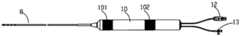
- FIG. 1is an overall schematic diagram of a visualized depth ablation catheter in Embodiment 1 of the present invention
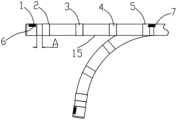
- Fig. 2is a schematic diagram of the adjustable bend section of the sheath in Example 1 of the present invention
- Fig. 3is a cross-sectional view of the adjustable bend section of the sheath in Example 1 of the present invention.
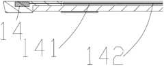
- Fig. 4is a partial enlarged view of the cross-sectional view of the adjustable bend section of the sheath in Example 1 of the present invention
- FIG. 5is an overall schematic diagram of the internal catheter in Embodiment 1 of the present invention.
- FIG. 6is a schematic cross-sectional view of the internal catheter in Embodiment 1 of the present invention.
- Fig. 7is a schematic diagram of the internal circulation function of the internal catheter in Example 1 of the present invention.
- Fig. 8is a schematic diagram of the catheter in the sheath in Example 1 of the present invention.
- Fig. 9is a schematic diagram of the catheter extending out of the sheath in Example 1 of the present invention.
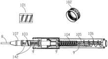
- Fig. 10is a schematic diagram of the interior of the handle assembly in Embodiment 1 of the present invention.
- Fig. 11is a partially enlarged view of the internal schematic diagram of the handle assembly in Embodiment 1 of the present invention.
- Embodiment 12is a schematic diagram of an external reference electrode in Embodiment 1 of the present invention.
- FIG. 13is a schematic diagram of the relationship between impedance and frequency in Embodiment 1 of the present invention.
- Fig. 14is a first application schematic diagram of a visualized depth ablation catheter in Embodiment 1 of the present invention.
- Fig. 15is a second application schematic diagram of a visualized depth ablation catheter in Embodiment 1 of the present invention.
- Fig. 16is a third application schematic diagram of a visualized depth ablation catheter in Embodiment 1 of the present invention.
- Fig. 17is a flowchart of the application of a visualized depth ablation catheter in Embodiment 1 of the present invention.
- Sheath tube head electrode2. Sheath tube electrode 2, 3. Sheath tube electrode 3, 4. Sheath tube electrode 4, 5. Sheath tube electrode 5, 6. Sheath tube head end positioning sensor, 7. Sheath rear end positioning sensor, 8. Adjustable curved sheath tube body, 9. Catheter, 91. Ablation head electrode, 92. Catheter positioning sensor, 93. Ablation electrode a, 94. Ablation electrode b, 95. Braided spiral wire , 96. Support pipe body, 97. Outer pipe body, 98. End pipe body, 99. Coolant channel, 10. Handle assembly, 101. Curved knob, 102. Screw-in mechanism knob, 103. Curved sliding block, 104. Screw-in motion mechanism, 105.
- Screw-in fixing mechanism106.
- Spiral wire107. Handle mandrel, 11. Organization, 12. Connector, 13. Tee, 14. Traction component, 141. Traction steel wire, 142 .Traction channel tube, 15. Adjustable elbow body section of sheath tube, 16. Sheath tube lumen, 17. Human body, 171.
- External reference electrodeA. Electrode spacing, B. Positioning sensor spacing, 18. Electrode close to tissue Or the resistance value measured at different frequencies inside the tissue, 19. The resistance value measured by the electrode at different frequencies in the blood.
- a visualized deep ablation catheteris composed of an adjustable curved sheath with a tube body 8, a handle assembly 10, a connector 12, and a tee 13, and an appropriate amount of heparin is injected into the tee at the handle end of the sheath Physiological saline, so that the inner catheter can pass freely in the sheath tube more smoothly and prevent thrombus, the sheath tube body distal end is provided with the sheath tube adjustable elbow body section 15, and the sheath tube adjustable elbow body section 15 is in the
- the curved shapecan be realized under the control of the handle assembly 10, and the principle of the adjustable curved pipe body section 15 of the sheath to realize the curved shape can be seen in Fig. 1, Fig.
- the insideis provided with an internal thread, and the internal thread inside the curved knob 101 cooperates with the external thread of the curved sliding block 103.
- the curved sliding blockwill be driven to move axially (the axial movement refers to the The length direction of the sheath moves, the same below), and then the traction assembly 14 moves axially, so that the adjustable elbow body section 15 of the sheath bends.
- the head end and the rear end of the adjustable curved sheathare respectively provided with a positioning sensor
- the head end of the adjustable curved sheathis provided with a positioning sensor 6
- the rear end of the adjustable curved sheathis provided with a positioning sensor 7,
- the positioning sensors 6 and 7are magnetic positioning sensors, and the coordinates of the positioning sensors 6 and 7 can be obtained in real time in the magnetic field area. After the coordinates of the positioning sensors 6 and 7 are determined, the bending shape of the adjustable curved sheath can be fitted according to the curve characteristics, And then display its bending shape on the device in real time.
- Another method for obtaining the bending shape of the adjustable curved sheathis to obtain the coordinates of the positioning sensors 6 and 7 in real time in the magnetic field area, and then obtain the position of the head and tail of the adjustable curved sheath. Since the adjustable curved sheath is also provided with The sheath tube electrode 2, the sheath tube electrode 3, the sheath tube electrode 4 and the sheath tube electrode 5, and these electrodes are arranged along the axial direction of the adjustable curved sheath tube, and are distributed between the head and tail ends of the adjustable curved sheath tube, therefore, can Through the electric field positioning of the sheath tube electrode 2, the sheath tube electrode 3, the sheath tube electrode 4 and the sheath tube electrode 5, the position of the electrodes is obtained, and the coordinates of the positioning sensors 6 and 7 acquired by the magnetic positioning sensor and the position of the sheath tube electrode positioned by the electric field Coordinates are combined, and the curved shape of the adjustable curved sheath is obtained through multi-point positioning.
- the positioning sensor 6 and the positioning sensor 7are respectively provided with a sheath head electrode 1 and a sheath electrode 5, since the positioning sensor 6 and the positioning sensor 7 can respectively determine their absolute coordinates T1 (x1, y1, z1) and T5 (x5, y5, z5), because the position of the sheath tip electrode 1 and the positioning sensor 6 is fixed, and the position of the sheath tube electrode 5 and the positioning sensor 7 is fixed, so the absolute coordinates of the positioning sensor 6 and the positioning sensor 7 are also the coordinates of the sheath tip electrode 1 and the sheath
- the absolute position coordinates of the tube electrode 5 and the absolute position coordinates of the sheath head electrode 1 and the sheath electrode 5are respectively T1' (x1, y1, z1) and T5' (x5, y5, z5).
- the sheath head electrode 1 and the sheath electrode 2, the sheath electrode 3, the sheath electrode 4, and the sheath electrode 5can display their relative position coordinates in real time under the electric field, Q1 (x, y, z), Q2 ( x, y, z), Q3(x, y, z), Q4(x, y, z), Q5(x, y, z), the basic principle of the relative position coordinates under the action of the electric field is, when set on the human body A voltage is applied between at least one pair of external reference electrodes. According to the relationship between the potential difference and the distance position, the position of the electrode (sheath electrode) in the electric field formed by the external reference electrode can determine its position in the electric field.
- the external reference electrodeis in space.
- the upper 3 pairscorrespond to the X-axis, Y-axis and Z-axis respectively, so the position coordinates of the electrodes in the electric field can be determined, so the relative positional relationship between the electrodes on the sheath can be determined, because the positioning sensor on the sheath can determine the electrode of the sheath head 1 and the absolute position of the sheath electrode 5, the relative position relationship of the electrode on the sheath is determined, so the absolute coordinates of all electrodes on the sheath can be deduced, and the bending shape of the sheath is obtained by connecting all coordinate points. Theoretically, the denser the electrode distribution on the sheath, the more accurate the curved shape.
- a hollow head electrodeis provided at the head end of the adjustable curved sheath tube, and a plurality of ring electrodes are sequentially arranged along the axial direction of the adjustable curved sheath tube.
- the sheath tube electrode 2 and the sheath tubeThe distance A between the tube head electrodes 1 is set in the range of 0.5-1.5mm, through the sheath tube electrode 2 and the sheath tube tip electrode 1, the intracavity electrophysiological map can be detected in real time in the heart to determine the specific position reached by the sheath tube tip, Since the electrophysiological signals at different parts of the cavity are different and have significant differences, as long as the electrophysiological signals between the electrodes can be accurately collected, the position of the sheath tip can be determined through the electrophysiological signals, and the electrophysiological signals collected between the electrodes The distance between the electrodes should be small enough and the distance should be fixed. This design is conducive to the accurate detection of local electrophysiological waveforms and avoids the interference of large-scale
- the adjustable elbow body section 15 of the sheath tubeis a flexible braided tube body, which can be bent and straightened freely under the control of the handle assembly 10, and cooperates with the magnetic positioning sensors 6 and 7 at the head and tail ends and the ring electrodes along the axial direction of the sheath tube , Physical model components and mapping can be performed under the 3D mapping system.
- a sheath lumen 16is provided inside the sheath for the catheter to move inside, and its material is preferably polytetrafluoroethylene with high lubricity.
- the sheath tube wallis also provided with a traction channel tube 142, and a traction assembly 14 is fixedly arranged on the sheath tube wall at the far end of the sheath tube.
- One end of the traction steel wire 141is fixedly connected with the traction assembly 14, and the other end of the traction steel wire is connected to the curved sliding
- the block 103is fixedly connected, driven by the axial movement of the curved sliding block 103, the traction steel wire 141 moves axially in the traction channel pipe 142, the traction steel wire 141 pulls the traction assembly 14, and under the tension of the traction steel wire 141 pulling the traction assembly 14 , the sheath bends or straightens accordingly.
- the position relationship diagram of the traction steel wire 141, the traction channel tube 142 and the traction assembly 14is shown in Fig. 4, which is an enlarged view of the cross section of the adjustable bend section of the sheath.
- an axially movable catheteris arranged in the body section 15 of the adjustable elbow of the sheath, and the catheter can be ablated by applying a pulsed electric field, or using radiofrequency energy for ablation.
- the tip of the catheteris provided with an ablation tip electrode 91, and the ablation tip electrode 91 is pointed.
- the tip of the ablation electrodeis fixed inside the tissue through the tip-shaped ablation tip electrode 91, as shown in Figures 5 and 6
- the outer surface of the ablation head electrodecan be in the form of a helical screw or a helical wire.
- the ablation head electrode 91is made of medical-grade stainless steel and has sufficient rigidity. After the ablation head electrode 91, the ablation electrode a93 and the ablation electrode b94 are arranged in sequence along the catheter axis. The ablation head electrode 91, the ablation electrode a93 and the ablation electrode b94 are all connected by independent electrode wires.
- the ablation head electrode 91 and the ablation electrode a93 and the ablation electrode b94are linearly distributed on the catheter with a distance of 0.50-3.0 mm.
- the ablation head electrode 91forms a bipolar electric field with the two rear-end electrodes a93 and ablation electrode b94 for tissue ablation.
- a bipolar electric fieldcan also be formed between the two electrodes 93 and 94 for tissue ablation, that is to say, any combination of bipolar discharges can be made between the ablation head electrode 91 and the two rear electrodes 93 and 94.
- the electrode lengthis 1-3mm.
- the ablation head electrode 91 and the two rear electrodes 93 and 94can both collect electrophysiological waveforms in the cavity.
- a magnetic positioning sensor 92is installed inside the ablation head electrode, and its position can be displayed in real time under the three-dimensional mapping system. Further, since the positional relationship between the ablation head electrode and the rear-end electrode is fixed, and the positional relationship with the magnetic positioning sensor is fixed, the intracavity electrophysiological waveform and magnetic positioning collected by the ablation head electrode 91 and the two rear-end electrodes 93 and 94 The coordinates of the sensor 92 can obtain the position and shape of the catheter head in real time, and accurately display the position and shape of the ablation head electrode 91 and the two electrodes 93 and 94 at the rear end on the system equipment.
- the positioning sensor 92 on the catheter and the positioning sensor 6 of the sheath bodycan determine their positional relationship B in real time, so the physical positional relationship between the catheter and the sheath can be displayed in real time on the system equipment , and then determine whether the ablation head electrode and other electrodes are out of the sheath.
- the catheterUnder the control of the screw-in mechanism knob 102 on the handle assembly 10, the catheter is advanced while rotating inside the sheath tube.
- the screw-in mechanism knob 102is provided with a screw-in fixing structure 105
- the screw-in fixing structure 105has an internal thread
- the screw-in movement mechanism 104is provided with an external thread
- the screw-in fixing structure 105has an internal thread and a screw-in fixing structure 105.
- the external thread on the screw-in motion mechanism 104is matched, the screw-in motion mechanism 104 moves under the limit of the screw-in fixed structure 105, the tube body of the catheter 9 is fixed on the axial direction of the screw-in motion mechanism 104, when the screw-in motion mechanism is manipulated
- the screw-in mechanism knob 102drives the internal screw-in movement mechanism 104 to perform a spiral movement on the screw-in fixing structure 105, and then the catheter performs a spiral feed movement in the sheath along the length direction of the sheath.
- the screw-in fixed structure 105plays a locking role on the screw-in kinematic mechanism 104, It is convenient to precisely control the moving process of the catheter 9 .
- the limiting effect of the screw-in fixing structure 105 on the screw-in motion mechanism 104is conducive to the stable entry of the ablation head electrode of the catheter 9 into the tissue and avoiding extensive trauma.
- the tail end of the catheter 9is connected with a helical wire 106 for
- the reason why the helical wire 106 is helicalis that when the catheter rotates and moves axially in the sheath, the wire should be rotated and stretched accordingly, and the wire is set to
- the helical shapeprevents the wire from being twisted during rotation, and the helical shape can be stretched and compressed, which is convenient to be stored and fixed inside the handle assembly.
- the traction steel wire 141enters the inside of the handle mandrel 107, the handle mandrel 107 is fixedly arranged inside the handle, the traction steel wire 141 is fixed on the curved sliding block 103, and the curved sliding block 103 can Move axially on the handle mandrel 107, the curved sliding block 103 has an external thread, which is matched with the curved knob 101, and the internal thread of the curved knob 101 is engaged with the external thread on the curved sliding block 103.
- the shape knob 101When the shape knob 101 rotates, it will drive the sliding block 103 to move axially on the handle mandrel 107, and then control the movement of the traction steel wire 141, so as to achieve the bending control of the sheath tube.
- the catheter 9moves in the adjustable curved sheath body 8, the catheter 9 passes through the handle mandrel 107 and the curved sliding block 103, but is not fixedly connected with the handle mandrel 107 and the curved sliding block 103, the catheter 9 It can freely rotate in the handle mandrel 107 and the curved sliding block 103 .
- Conduit 9enters in screw-in kinematic mechanism 104 by handle mandrel 107 and is fixed on its afterbody, and screw-in kinematic mechanism 104 is cylinder, has external thread, can be screwed into fixing mechanism 105 (has internal thread, and is fixed on handle Inside) rotates and moves axially, and the screw-in kinematic mechanism 104 also engages with the screw-in mechanism knob 102.
- the screw-in mechanism knob 102has an internal thread, and the screw-in kinematic mechanism 104 can be driven to move axially when the screw-in mechanism knob 102 rotates , to control the axial movement of the catheter 9 relative to the sheath.
- the sheathis fixed on the handle mandrel 107 and is relatively independent from the catheter 9, and the catheter 9 can move independently in the sheath.
- the ablation head electrode and the electrode of the catheterare arranged on the end tube body of the catheter.
- the material of the cathetercan be polyimide or polyether ether ketone.
- a braided helical wire 95is arranged on the proximal end of the end tube body, and the braided helical wire 95 is made of metal stainless steel or nickel-titanium alloy wire It is used to increase the torque of the tube body without affecting the elasticity of the tube body.
- a support tube body 96is arranged inside.
- the support tube body 96can be a plastic tube body such as polyimide.
- an outer tube body 97is arranged on the outside of the braided helical wire 95.
- the outer tube body 97is used to protect the tube body.
- the material of the outer tube body 97can be made of polyurethane.
- the cathetercan perform both radiofrequency ablation and high-voltage pulsed electric field ablation, in which high-voltage pulsed electric field ablation is to apply a short high voltage to the tissue to generate a local high electric field of hundreds of volts per centimeter on the tissue, and the local high electric field passes through the cell membrane Pores are created to disrupt cell membranes.
- An applied electric field at the membrane greater than the cellular thresholdcauses the pore not to close, and this electroporation is irreversible, thereby allowing the exchange of biomolecular material across the membrane, resulting in necrosis or apoptosis.
- a certain distance Dis required between the electrodes of the ablation head and between the electrodes.
- the electric field strength and distribution of the electrodeshave a significant relationship with the electrode spacing and the cross-sectional area of the electrodes.
- High-voltage pulse ablationneeds to be considered when designing the electrodes.
- Electrode diameter, spacing, field strength and effective depth under specific energycan reach effective depth without ionization.
- the electric field strengthis the largest on the surface of the electrode and gradually decays outwards. At the same time, the field strength gradually decays from the electrode to the center of the electrode.
- the field strength analysis of different spacingis carried out.
- the field strength at the center of the electrodesdecreases with the increase of the spacing, and the field strength at the edge of the electrodes decreases with the increase of the spacing, and there is no change after reaching a certain distance.
- the field strength analysis of different electrode cross-sectional areasis carried out.
- the field strength in the center of the electrodesincreases with the increase of the cross-sectional area, but the change is significant.
- the field strength at the edge of the electrodesincreases with the increase of the cross-sectional area.
- the designselects the electrode diameter with uniform field strength distribution, the electrode diameter Preferably 1-2mm.
- the amplitude of the pulse electric fieldis set between 500V-4000V, which can be set according to the desired effect.
- the pulsed electric fieldis used to precisely ablate the lesion tissue and avoid damage to the surrounding blood vessels and conduction tissue.
- the cathetercan also use radio frequency energy, as shown in Figure 7, the ablation head electrode 91 and the back-end electrodes 93 and 94 can be used as ablation electrodes for radio frequency discharge ablation, in order to achieve high-voltage pulse discharge At the same time, radio frequency ablation discharge can also be performed, and the insulation strength between the ablation head electrode 91 and the back-end electrodes 93 and 94 should be sufficient and sufficient, at least able to withstand a DC voltage of 4000V. Due to the ablation inside the tissue, open perfusion ablation cannot be performed, so an internal circulating cooling liquid is required for ablation.
- radiofrequency ablationis selected when large-area destructive ablation is required, and high-voltage pulsed electric field ablation is often used when single-point ablation is required.
- the quality of the ablation effecthas a great relationship with the degree of contact between the ablation electrode and the tissue. Therefore, the detection of the degree of contact has also been improved in the technical solution.
- the external reference electrode 171is applied on the torso of the human body 17, the impedance value can be measured in real time between the electrode on the catheter and the external reference electrode 171, and the distance between the ablation head electrode on the catheter and the external reference electrode 171 Impedance values can also be measured in real time.
- the impedance of human muscle tissueis sensitive to the influence of frequency, and the impedance varies greatly at different frequencies, while the impedance of electrodes in blood is less affected by frequency.
- the electrode and ablationcan be determined in real time according to the difference in impedance affected by frequency.
- the position of the electrode in the tissuemay be close to the tissue, or inside the tissue, or in the blood.
- the reliability and safety of ablationcan be improved.
- adopt high-frequency acquisition signal and low-frequency acquisition signal to measure the impedance of electrode simultaneouslyobtain the impedance value Ra under the low frequency and the impedance value Rb under the high frequency, judge according to the difference of impedance value Ra and impedance value Rb The position of the measuring electrode where the signal is acquired.
- the impedance between the measuring electrode and the external reference electrodeis collected at the same time, and the impedance values Ra and Rb are obtained.
- the specific application frequencycan be set according to the actual application requirements.
- the Ra-Rb value in the bloodis ⁇ , and the ⁇ value is 0-100 ⁇ .
- the specific valueis determined according to the actual measurement and statistics of the specific application environment and frequency. If 0 ⁇ 10 ⁇ , the electrode is in the blood; if 10 ⁇ 100 ⁇ , the electrode is adjacent to the tissue or inside the tissue.
- the ablation electrodeWhen the electrode tail at the head end of the sheath is attached to the tissue, the ablation electrode is easily scratched and the internal tissue is easily scratched. Since the electrode tail of the ablation head has no support, it cannot be smoothly screwed into the tissue. Therefore, before the ablation head electrode is screwed into the tissue, it is necessary to determine whether the ablation electrode and the ablation head electrode are inside the blood or the tissue, so as to determine whether the ablation electrode is screwed in. Since the detection is the impedance between all electrodes and the external reference electrode 107, there is the same reference electrode, the impedance detection data is accurate, and the position of each electrode or the ablation head electrode and the tissue can be accurately measured, so as to prevent the electrode from being out of position. Ineffective ablation is caused by the internal discharge of the tissue, and the safety risk caused by the electrode of the ablation head passing through the muscle tissue to the other side for ablation can be avoided.
- Figure 14-16shows the schematic diagram of the sheath and the catheter used together.
- the head of the sheathis perpendicular to the expected tissue surface and stably abuts it. If it is not abutted, readjust the sheath The position of the head end and the tissue is stable. If it is stable, use the electrode at the head end of the sheath to detect whether the anatomical position is safe. If it is safe, control the catheter in the sheath to extend out of the sheath and enter the tissue.
Landscapes
- Health & Medical Sciences (AREA)
- Surgery (AREA)
- Engineering & Computer Science (AREA)
- Life Sciences & Earth Sciences (AREA)
- Biomedical Technology (AREA)
- Public Health (AREA)
- Nuclear Medicine, Radiotherapy & Molecular Imaging (AREA)
- Veterinary Medicine (AREA)
- General Health & Medical Sciences (AREA)
- Heart & Thoracic Surgery (AREA)
- Medical Informatics (AREA)
- Molecular Biology (AREA)
- Animal Behavior & Ethology (AREA)
- Physics & Mathematics (AREA)
- Otolaryngology (AREA)
- Plasma & Fusion (AREA)
- Cardiology (AREA)
- Robotics (AREA)
- Surgical Instruments (AREA)
Abstract
Description
Translated fromChinese本发明涉及医用电生理导管技术和心脏电生理消融领域,特别是涉及一种可视化深度消融导管。The invention relates to the field of medical electrophysiological catheter technology and cardiac electrophysiological ablation, in particular to a visualized deep ablation catheter.
射频消融与脉冲电场消融可被应用于组织消融,射频消融是作为一种常用的安全手段,但应用在密闭的组织内部时容易形成组织结痂碳化等问题,因此需要借助灌注冷却电极的方式。脉冲电场作为一种高效、安全的消融能量源一直在被国内外学者研究,近年来脉冲电场技术取得了巨大进展尤其是在肿瘤消融领域,将脉冲电场消融原理应用于心脏消融领域也是目前国内外研究的方向。脉冲电场技术是将短暂的高电压施加到组织可以产生每厘米数百伏特的局部高电场,局部高电场通过在细胞膜中产生孔隙来破坏细胞膜。在膜处所施加的电场大于细胞阈值使得孔隙不闭合,这种电穿孔是不可逆的,由此允许生物分子材料穿过膜进行交换,从而导致细胞坏死或凋亡。Radiofrequency ablation and pulsed electric field ablation can be applied to tissue ablation. Radiofrequency ablation is a commonly used safety method, but it is easy to cause scab carbonization and other problems when it is applied in a closed tissue. Therefore, it is necessary to use perfusion to cool the electrode. As an efficient and safe ablation energy source, pulsed electric field has been studied by scholars at home and abroad. In recent years, pulsed electric field technology has made great progress, especially in the field of tumor ablation. Direction of the research. Pulsed electric field technology is to apply a brief high voltage to the tissue to generate a local high electric field of hundreds of volts per centimeter, which destroys the cell membrane by creating pores in the cell membrane. An applied electric field at the membrane greater than the cellular threshold causes the pore not to close, and this electroporation is irreversible, thereby allowing the exchange of biomolecular material across the membrane, resulting in necrosis or apoptosis.
但对于在组织内部较深的病灶位置,现在无论是射频技术、冷冻技术、以及脉冲电场均无法达到深度消融,且在消融中还会将正常组织进行消融,因此本发明提供一种在定位导航与贴靠检测下精确、安全将电极递送至目标组织区域进行消融的消融导管,能实现心肌的深度消融,以及消融导管的形态检测、定位、贴靠检测等功能。However, for the deep lesion position inside the tissue, neither radio frequency technology, freezing technology, nor pulsed electric field can achieve deep ablation, and normal tissue will be ablated during the ablation, so the present invention provides a positioning navigation The ablation catheter accurately and safely delivers the electrode to the target tissue area for ablation under the abutment detection, which can realize the deep ablation of the myocardium, as well as the shape detection, positioning, and adhering detection of the ablation catheter.
目前,导管的设计存在以下问题:At present, the design of the catheter has the following problems:
1、传统消融导管中,导管与鞘管为分开独立使用,不便于术者操作,导管相对于鞘管的运动较为灵活,针对于对组织内部且较深的病灶进行处理,导管与鞘管之间的相对位置的精度不够。1. In the traditional ablation catheter, the catheter and the sheath are used separately and independently, which is not convenient for the operator to operate. The movement of the catheter relative to the sheath is more flexible. It is aimed at treating deep lesions inside the tissue. The distance between the catheter and the sheath The accuracy of the relative position between them is not enough.
2.目前鞘管仅作为导管通路,需要借助大量X射线,才能实现鞘管和导管的定位和形态检测,增加术者与患者射线曝光量,需要一种更为准确和便捷的能实现定位和形态检测的导管和检测方法。2. At present, the sheath is only used as a catheter access, and a large number of X-rays are needed to realize the positioning and shape detection of the sheath and catheter. To increase the radiation exposure of the surgeon and the patient, a more accurate and convenient positioning and detection method is needed. Conduits and detection methods for morphological detection.
3、在偏心外膜以及组织内部且较深的病灶,传统消融方式难以到达其深度位置,影响消融的效果,且会损伤周围健康组织,在获取导管鞘管定位和形态的前提下,需要实现导管和组织的贴靠检测组件和方法。目前电极在组织内或血液内与组织贴靠情况采用电生理波形进行判断,由于电生理信号在传输过程中易受干扰,因此该方式存在不准确性。现有技术中还有检测导管和组织贴靠的压力,通过检测导管和组织贴靠的压力来判断导管与组织之间的贴靠程度,但是采用压力检测方式需要获取较为精确的压力值以及基于该压力值进行计算,实现的成本极高,且当导管有多个电极时,通常导管为立体结构,电极与组织之间的压力值无法完全反应出导管与组织的贴靠程度。并且无法通过压力检测方式提供可能性。3. For eccentric adventitia and deep lesions inside the tissue, traditional ablation methods are difficult to reach the deep position, which will affect the effect of ablation and damage the surrounding healthy tissue. On the premise of obtaining the positioning and shape of the catheter sheath, it is necessary to achieve Catheter and tissue abutment detection assembly and method. Currently, electrophysiological waveforms are used to judge the adhesion of electrodes to tissues in tissue or blood. Since electrophysiological signals are susceptible to interference during transmission, this method is inaccurate. In the prior art, there is also detection of the pressure between the catheter and the tissue, and the degree of adhesion between the catheter and the tissue can be judged by detecting the pressure of the catheter and the tissue. However, the pressure detection method needs to obtain more accurate pressure values and based on The calculation of the pressure value is extremely costly, and when the catheter has multiple electrodes, usually the catheter has a three-dimensional structure, and the pressure value between the electrodes and the tissue cannot fully reflect the degree of adhesion between the catheter and the tissue. And the possibility cannot be provided by means of pressure detection.
4.目前的消融方式能量选择单一,一根导管仅能使用一种消融能量模式,需要提供可以同时进行射频消融和高压脉冲消融的导管。4. The current ablation method has a single energy selection, and one catheter can only use one ablation energy mode, so it is necessary to provide a catheter that can perform radiofrequency ablation and high-voltage pulse ablation at the same time.
发明内容Contents of the invention
本发明为了克服上述问题,对鞘管和导管进行改进,提出了一种可视化深度消融导管。In order to overcome the above problems, the present invention improves the sheath tube and catheter, and proposes a visualized depth ablation catheter.
为了实现上述发明目的,本发明提供了以下技术方案:In order to realize the above-mentioned purpose of the invention, the present invention provides the following technical solutions:
一种可视化深度消融导管,包括导管和安装在所述导管外的鞘管,还包括手柄组件和安装在所述手柄组件内的轴向移动驱动部件,所述轴向移动驱动部件在手柄组件内能够做螺旋运动,并驱动所述导管运动。A visualized depth ablation catheter, including a catheter and a sheath installed outside the catheter, and also includes a handle assembly and an axially moving driving part installed in the handle assembly, and the axially moving driving part is inside the handle assembly Capable of a helical motion and drives the catheter in motion.
现有技术中,虽然导管在鞘管沿鞘管长度方向移动,但是都是人为控制的自由移动,导管相对于鞘管移动多少全靠操作人员的手感,控制精度有限,在本方案中,在导管末端手柄组件内设置了轴向移动驱动部件,导管在鞘管中的相对运动受到轴向移动驱动部件的限制,通过轴向移动驱动部件在手柄组件内的螺旋运动驱动导管沿鞘管长度方向移动,便于精确控制导管与鞘管之间的相对位置。In the prior art, although the catheter moves along the length of the sheath in the sheath, it is free to move under human control. How much the catheter moves relative to the sheath depends on the operator's hand feeling, and the control accuracy is limited. In this solution, the An axial movement driving part is set in the handle assembly at the end of the catheter, and the relative movement of the catheter in the sheath is limited by the axial movement driving part. Movement for precise control of the relative position between the catheter and the sheath.
作为优选方案,所述导管上还设置有弯型控制部件,鞘管头端上设置有牵引部件,所述弯型控制部件与所述牵引部件固定连接,所述弯型控制部件在所述鞘管长度方向上移动,使得所述牵引部件带动所述鞘管弯曲。As a preferred solution, the catheter is also provided with a curved control component, and the sheath head is provided with a traction component, the curved control component is fixedly connected with the traction component, and the curved control component is placed on the sheath The tube moves along the length direction, so that the traction member drives the sheath tube to bend.
导管上的弯型控制部件在所述鞘管长度方向上移动,使得弯型控制部件与鞘管头端上的牵引部件之间的相对位置缩短,但是弯型控制部件与牵引部件固定连接,所以在相对距离缩短的压力下,鞘管发生弯曲。The curved control part on the catheter moves in the length direction of the sheath, so that the relative position between the curved control part and the traction part on the head end of the sheath is shortened, but the curved control part is fixedly connected with the traction part, so Under the pressure of the relative distance shortening, the sheath bends.
作为优选方案,所述鞘管包括鞘管可调弯管体段15、弯型滑动块103和旋转弯型旋钮101,所述弯型滑动块103与牵引组件14通过牵引钢丝141连接,所述牵引组件14固定在所述鞘管远端的内壁上,所述弯型滑动块103与所述旋转弯型旋钮101通过外螺纹和内螺纹啮合,As a preferred solution, the sheath includes an adjustable
所述弯型滑动块(103)在所述旋转弯型旋钮(101)的带动下沿牵引钢丝(141)靠近所述牵引组件(14),使得所述鞘管可调弯管体段(15)弯曲。The curved sliding block (103) is driven by the rotating curved knob (101) to approach the traction assembly (14) along the traction wire (141), so that the sheath can adjust the curved body section (15 )bending.
弯型滑动块103与所述旋转弯型旋钮101通过外螺纹和内螺纹啮合,因此,当旋转弯型旋钮101以鞘管轴心为中心旋转时,弯型滑动块103并不旋转,而是在螺纹的限位作用下,沿着鞘管长度方向移动。The curved sliding
作为优选方案,所述鞘管可调弯管体段15的两端设置有磁定位传感器,并且所述鞘管可调弯管体段15的轴向上设置有多个电极,通过所述磁定位传感器的坐标以及所述电极的坐标,确定鞘管可调弯管体段15的弯曲形态。As a preferred solution, magnetic positioning sensors are provided at both ends of the adjustable sheath
作为优选方案,所述轴向移动驱动部件包括旋入运动机构104,所述导管固定在所述旋入运动机构104上,还包括固定在鞘管内的旋入固定结构105,通过螺纹和螺纹槽的啮合实现所述旋入运动机构104相对于所述旋入固定结构105做螺旋运动。As a preferred solution, the axial movement driving part includes a screw-in
由于螺纹和螺纹槽的啮合关系是确定的,当旋入运动机构104停止移动时,旋入固定结构105对旋入运动机构104有锁定的作用,不会造成旋入运动机构104的自由滑动,并且,可以准确计算出旋入运动机构104旋转一周,旋入运动机构104带动导管在鞘管长度方向上移动的距离,提高了导管和鞘管之间相对位置关系控制的精准度。Since the engagement relationship between the thread and the thread groove is definite, when the screw-in
作为优选方案,还包括螺旋导线6,所述螺旋导线6为螺旋状,与所述旋入固定结构105相啮合,用于给所述导管上的定位传感器和电极提供电源和/或传输信号。As a preferred solution, a
由于需要采集导管上的数据,因此,需要在导管上设置导线,将导线设置为螺旋状,一方面,螺旋导线按照旋入固定结构105的轨道与旋入运动机构104同步旋转,不会因为旋入运动机构104的旋转而使导线在鞘管内发生缠绕甚至拧断导线,另一方面,螺旋状的导线延展性更好,随着旋入运动机构104的推进而拉伸,随着旋入运动机构104的退后而压缩,便于导线的收纳。Due to the need to collect data on the catheter, it is necessary to set a wire on the catheter and set the wire in a helical shape. On the one hand, the helical wire rotates synchronously with the screw-in
作为优选方案,通过获取所述导管上的电极的阻抗值,可以判断电极与组织的贴靠状态,具体步骤为:As a preferred solution, by obtaining the impedance value of the electrode on the catheter, the adhering state of the electrode and the tissue can be judged, and the specific steps are:
S1,获取不同频率下所述导管上电极与人体外的外部参考电极之间的阻抗值,并计算不同频率下阻抗值的差值;S1, obtaining the impedance value between the electrode on the catheter and the external reference electrode outside the human body at different frequencies, and calculating the difference of the impedance value at different frequencies;
S2,若所述差值在第一阈值范围,则电极与组织贴靠或者电极在组织内部,若所述差值在第二阈值范围,则电极在血液中。S2. If the difference is within the first threshold range, the electrode is in contact with the tissue or inside the tissue; if the difference is within the second threshold range, the electrode is in the blood.
作为优选的具体方案,步骤S1具体包括以下步骤:采用高频采集信号测量所述导管上电极与人体外的外部参考电极171之间的阻抗值,得到高频下的阻抗值Rb;并且采用低频采集信号测量同一电极与人体外的外部参考电极171之间的阻抗值,得到低频下的阻抗值Ra,所述低频下的阻抗值Ra与所述高频下的阻抗值Rb之间的差值为α;As a preferred specific solution, step S1 specifically includes the following steps: using high-frequency acquisition signals to measure the impedance value between the electrode on the catheter and the
相应的,步骤S2中,若0≤α≤10Ω,则所述电极在血液中;若10<α≤100Ω,所述电极在与组织贴靠或在组织内部。Correspondingly, in step S2, if 0≤α≤10Ω, the electrode is in the blood; if 10<α≤100Ω, the electrode is adjacent to the tissue or inside the tissue.
作为优选方案,所述导管上设置了包括消融头电极在内的多个电极,所述多个电极用于输出射频能量或者高压脉冲信号。As a preferred solution, multiple electrodes including electrodes of the ablation head are provided on the catheter, and the multiple electrodes are used to output radio frequency energy or high-voltage pulse signals.
作为优选方案,所述消融头电极呈尖端状,用于将导管电极进入组织内部并固定,并且所述导管的轴向上设置了多个电极,所述消融头电极与第一个电极之间的间距为在0.5-3mm的范围内。As a preferred solution, the electrode of the ablation head has a pointed shape, which is used to enter and fix the catheter electrode into the tissue, and a plurality of electrodes are arranged in the axial direction of the catheter, and the electrode between the ablation head and the first electrode is The spacing is in the range of 0.5-3mm.
与现有技术相比,本发明的有益效果:Compared with prior art, the beneficial effect of the present invention:
1、本发明中的消融导管,将鞘管和导管进行了一体化设计,导管在鞘管中的相对运动受到手柄组件内轴向移动驱动部件的限制,因此,导管相对于鞘管的运动可以受到更精确的控制,针对于对组织内部且较深的病灶进行处理,能精确控制导管与鞘管之间的相对位置,以实现对病灶的精确处理。1. In the ablation catheter of the present invention, the sheath tube and the catheter are integrated. The relative movement of the catheter in the sheath tube is limited by the axial movement of the driving part in the handle assembly. Therefore, the movement of the catheter relative to the sheath tube can be Under more precise control, for the treatment of deep lesions inside the tissue, the relative position between the catheter and the sheath can be precisely controlled to achieve precise treatment of the lesions.
2、不仅通过鞘管可调弯段首尾端的磁定位传感器获取鞘管可调弯段的首位位置信息,还通过导管上的多个电极,确定鞘管和导管的弯曲形态。通过磁定位传感器的定位和电极的定位相结合的方式,实时准确地获取导管的形态和位置。2. Not only obtain the first position information of the adjustable bending section of the sheath through the magnetic positioning sensor at the head and tail of the adjustable bending section of the sheath, but also determine the bending shape of the sheath and the catheter through multiple electrodes on the catheter. Through the combination of the positioning of the magnetic positioning sensor and the positioning of the electrodes, the shape and position of the catheter can be accurately obtained in real time.
3、本发明的方案中,通过导管上的多个电极,获取多个电极的阻抗值,通过阈值对阻抗值进行判断,从而准确判断出电极与组织贴靠的程度。3. In the solution of the present invention, the impedance values of the multiple electrodes are obtained through the multiple electrodes on the catheter, and the impedance values are judged by the threshold value, so as to accurately judge the degree of adhesion between the electrodes and the tissue.
4.在导管上布设了多个电极,并且考虑了电极间的间距,在高压脉冲下,由于电极间的间距做了合理设置,不会造成电离现象,所以,导管上的电极既可以进行射频消融,也可以实现高压脉冲消融。4. A plurality of electrodes are arranged on the catheter, and the distance between the electrodes is considered. Under the high-voltage pulse, due to the reasonable setting of the distance between the electrodes, ionization will not be caused. Therefore, the electrodes on the catheter can perform radio frequency Ablation, high-voltage pulse ablation can also be achieved.
图1为本发明实施例1中一种可视化深度消融导管整体示意图;FIG. 1 is an overall schematic diagram of a visualized depth ablation catheter in Embodiment 1 of the present invention;
图2为本发明实施例1中鞘管可调弯段示意图;Fig. 2 is a schematic diagram of the adjustable bend section of the sheath in Example 1 of the present invention;
图3为本发明实施例1中鞘管可调弯段剖面图;Fig. 3 is a cross-sectional view of the adjustable bend section of the sheath in Example 1 of the present invention;
图4为本发明实施例1中鞘管可调弯段剖面图的部分放大图;Fig. 4 is a partial enlarged view of the cross-sectional view of the adjustable bend section of the sheath in Example 1 of the present invention;
图5为本发明实施例1中内部导管整体示意图;5 is an overall schematic diagram of the internal catheter in Embodiment 1 of the present invention;
图6为本发明实施例1中内部导管剖面示意图;6 is a schematic cross-sectional view of the internal catheter in Embodiment 1 of the present invention;
图7为本发明实施例1中内部导管具有内循环功能示意图;Fig. 7 is a schematic diagram of the internal circulation function of the internal catheter in Example 1 of the present invention;
图8为本发明实施例1中导管在鞘管内示意图;Fig. 8 is a schematic diagram of the catheter in the sheath in Example 1 of the present invention;
图9为本发明实施例1中导管伸出鞘管示意图;Fig. 9 is a schematic diagram of the catheter extending out of the sheath in Example 1 of the present invention;
图10为本发明实施例1中手柄组件内部示意图;Fig. 10 is a schematic diagram of the interior of the handle assembly in Embodiment 1 of the present invention;
图11为本发明实施例1中手柄组件内部示意图的部分放大图;Fig. 11 is a partially enlarged view of the internal schematic diagram of the handle assembly in Embodiment 1 of the present invention;
图12为本发明实施例1中外部参考电极示意图;12 is a schematic diagram of an external reference electrode in Embodiment 1 of the present invention;
图13为本发明实施例1中阻抗与频率关系示意图;13 is a schematic diagram of the relationship between impedance and frequency in Embodiment 1 of the present invention;
图14为本发明实施例1中一种可视化深度消融导管应用示意图一;Fig. 14 is a first application schematic diagram of a visualized depth ablation catheter in Embodiment 1 of the present invention;
图15为本发明实施例1中一种可视化深度消融导管应用示意图二;Fig. 15 is a second application schematic diagram of a visualized depth ablation catheter in Embodiment 1 of the present invention;
图16为本发明实施例1中一种可视化深度消融导管应用示意图三;Fig. 16 is a third application schematic diagram of a visualized depth ablation catheter in Embodiment 1 of the present invention;
图17为本发明实施例1中一种可视化深度消融导管应用流程图。Fig. 17 is a flowchart of the application of a visualized depth ablation catheter in Embodiment 1 of the present invention.
附图标记:1.鞘管头电极、2.鞘管电极2、3.鞘管电极3、4.鞘管电极4、5.鞘管电极5、6.鞘管头端定位传感器、7.鞘管后端定位传感器、8.可调弯鞘管管体、9.导管、91.消融头电极、92.导管定位传感器、93.消融电极a、94.消融电极b、95.编织螺旋丝、96.支撑管体、97.外管体、98.末端管体、99.冷却液通道、10.手柄组件、101.弯型旋钮、102.旋入机构旋钮、103.弯型滑动块、104.旋入运动机构、105.旋入固定机构、106.螺旋导线、107.手柄芯轴、11.组织、12.连接器、13.三通、14.牵引组件、141.牵引钢丝、142.牵引通道管、15.鞘管可调弯管体段、16.鞘管腔道、17.人体、171.外部参考电极、A.电极间距、B.定位传感器间距、18.电极贴靠组织或在组织内部不同频率下测量的阻值、19.电极在血液中不同频率下测量的阻值。Reference signs: 1. Sheath tube head electrode, 2.
下面结合试验例及具体实施方式对本发明作进一步的详细描述。但不应将此理解为本发明上述主题的范围仅限于以下的实施例,凡基于本发明内容所实现的技术均属于本发明的范围。The present invention will be further described in detail below in conjunction with test examples and specific embodiments. However, it should not be understood that the scope of the above subject matter of the present invention is limited to the following embodiments, and all technologies realized based on the content of the present invention belong to the scope of the present invention.
实施例1Example 1
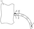
如图1、图2所示,一种可视化深度消融导管由可调弯鞘管有管体8、手柄组件10、连接器12、三通13组成,鞘管手柄端的三通内注入适量的肝素化生理盐水,以使内部导管能更佳顺畅的在鞘管内自由穿行并防止血栓,鞘管管体远端设置有鞘管可调弯管体段15,鞘管可调弯管体段15在手柄组件10控制下可实现弯型,鞘管可调弯管体段15实现弯型的原理具体参见图1、图7和图9,弯型滑动块103与牵引组件14连接,弯型旋钮101内部设置有内螺纹,弯型旋钮101内部的内螺纹与弯型滑动块103的外螺纹配合,当操控旋转弯型旋钮101时,将带动弯型滑动块进行轴向运动(轴向运动指沿鞘管长度方向上运动,下同),进而使牵引组件14轴向运动,使鞘管可调弯管体段15弯曲。As shown in Figure 1 and Figure 2, a visualized deep ablation catheter is composed of an adjustable curved sheath with a tube body 8, a
如图2所示,可调弯鞘管头端与后端分别设置有定位传感器,可调弯鞘管的头端设置了定位传感器6,可调弯鞘管的后端设置了定位传感器7,定位传感器6和7为磁定位传感 器,在磁场区域内可实时获取定位传感器6和7的坐标,在确定定位传感器6和7的坐标后可以根据曲线特性拟合可调弯鞘管的弯曲形态,进而实时在设备上显示其弯曲形态。As shown in Figure 2, the head end and the rear end of the adjustable curved sheath are respectively provided with a positioning sensor, the head end of the adjustable curved sheath is provided with a
另一种可调弯鞘管的弯曲形态获取方法为,在磁场区域内实时获取定位传感器6和7的坐标,就得到了可调弯鞘管首尾的位置,由于可调弯鞘管还设置了鞘管电极2、鞘管电极3、鞘管电极4和鞘管电极5,并且这些电极沿可调弯鞘管的轴向设置,分布在可调弯鞘管的首尾端之间,因此,可以通过鞘管电极2、鞘管电极3、鞘管电极4和鞘管电极5的电场定位,获取电极的位置,将磁定位传感器获取的定位传感器6和7的坐标和电场定位的鞘管电极的坐标相结合,通过多点定位就获取了该可调弯鞘管的弯曲形态。定位传感器6与定位传感器7上分别设置有鞘管头电极1与鞘管电极5,由于定位传感器6与定位传感器7可以实时分别确定其绝对坐标T1(x1,y1,z1)与T5(x5,y5,z5),由于鞘管头电极1与定位传感器6位置固定,鞘管电极5与定位传感器7位置固定,因此定位传感器6与定位传感器7的绝对坐标也即是鞘管头电极1与鞘管电极5的绝对位置坐标,鞘管头电极1与鞘管电极5的绝对位置坐标,分别为T1’(x1,y1,z1)与T5’(x5,y5,z5)。由于鞘管头电极1与鞘管电极2、鞘管电极3、鞘管电极4、鞘管电极5在电场下可实时显示其相对位置坐标,分别为Q1(x,y,z)、Q2(x,y,z)、Q3(x,y,z)、Q4(x,y,z)、Q5(x,y,z),电场作用下的相对位置坐标基本原理为,在设置在人体上的至少一对外部参考电极之间加载电压,根据电势差与距离位置关系,电极(鞘管电极)在外部参考电极形成的电场中的位置可以确定其在电场中的位置,外部参考电极为在空间上3对,分别对应X轴Y轴Z轴,因此就可以确定电极在电场中位置坐标,因此可以确定鞘管上电极之间的相对位置关系,由于鞘管上定位传感器可以确定鞘管头电极1与鞘管电极5绝对位置,鞘管上电极相对位置关系确定,因此可以推导出鞘管上所有电极绝对坐标,将所有坐标点连线即为鞘管的弯曲形态。理论上鞘管上的电极分布越密集弯曲形态越准确。Another method for obtaining the bending shape of the adjustable curved sheath is to obtain the coordinates of the
进一步的,如图2所示,可调弯鞘管的鞘管头端设置中空的头电极,沿可调弯鞘管的轴向依次设置多个环电极,特别的,鞘管电极2与鞘管头电极1之间的间距A设置在0.5-1.5mm范围内,通过鞘管电极2与鞘管头电极1可以在心内实时检测腔内电生理图以确定鞘管头端达到的具体位置,由于腔内不同部位上的电生理信号不同且具有显著的差异,因此只要能精确采集到电极之间电生理信号即可通过电生理信号判定鞘管头端到达的位置,电极之间采集电生理信号时电极间距应足够小且间距固定,这样设计以利于精确检测局部电生理波形,避免大范围的远场电生理波形干扰。Further, as shown in FIG. 2, a hollow head electrode is provided at the head end of the adjustable curved sheath tube, and a plurality of ring electrodes are sequentially arranged along the axial direction of the adjustable curved sheath tube. In particular, the sheath tube electrode 2 and the sheath tube The distance A between the tube head electrodes 1 is set in the range of 0.5-1.5mm, through the sheath tube electrode 2 and the sheath tube tip electrode 1, the intracavity electrophysiological map can be detected in real time in the heart to determine the specific position reached by the sheath tube tip, Since the electrophysiological signals at different parts of the cavity are different and have significant differences, as long as the electrophysiological signals between the electrodes can be accurately collected, the position of the sheath tip can be determined through the electrophysiological signals, and the electrophysiological signals collected between the electrodes The distance between the electrodes should be small enough and the distance should be fixed. This design is conducive to the accurate detection of local electrophysiological waveforms and avoids the interference of large-scale far-field electrophysiological waveforms.
鞘管可调弯管体段15为柔性的编织管体,在手柄组件10控制下可自由弯曲伸直,配合头端与尾端的磁定位传感器6和7以及沿鞘管轴向上的环电极,在三维标测系统下可进行物理模型构件与标测。如图3所示,鞘管内部设置有鞘管腔道16,用于导管在其内部活动,其材料优选为润滑性较高的聚四氟乙烯。鞘管壁上还设置有牵引通道管142,在鞘管远端的鞘管壁上固定设置了牵引组件14,牵引钢丝141的一端与牵引组件14固定连接,牵引钢丝的另一端与弯型滑动块103固定连接,在弯型滑动块103轴向移动的带动下,牵引钢丝141在牵引通道管142内轴向移动,牵引钢丝141拉动牵引组件14,在牵引钢丝141拉动牵引组件14的拉力下,鞘管随着弯曲或伸直。牵引钢丝141、牵引通道管142和牵引组件14的位置关系图详见图4,鞘管可调弯段剖面图的放大图。The adjustable
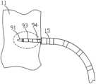
如图5-10,鞘管可调弯管体段15内设置有可轴向移动的导管,导管可应用脉冲电场进行消融,也可以使用射频能量进行消融。As shown in Fig. 5-10, an axially movable catheter is arranged in the
导管头端设置有消融头电极91,消融头电极91呈尖端状,当导管进入组织内部时,通过尖端状的消融头电极91将消融电极的头端固定在组织内部,如图5和图6所示,消融头电极的外表面可以为螺旋状的螺钉形式也可以为螺旋丝形式,消融头电极91为符合医用级不锈钢制成,并具有足够的刚性。消融头电极91后沿着导管轴向上还依次设置消融电极a93、消融电极b94,消融头电极91以及消融电极a93和消融电极b94均有独立的电极导线连接,消融头电极91以及消融电极a93和消融电极b94呈线性分布在导管上,其间距为0.50-3.0mm,使用高压脉冲放电时,消融头电极91与后端两个电极a93和消融电极b94形成双极电场进行组织消融,后端两个电极93和94之间也可以形成双极电场进行组织消融,也即是说,消融头电极91与后端两个电极93和94三个电极之间可以任意组合双极放电,消融头电极长度为1-3mm。消融头电极91与后端两个电极93和94均可以采集腔内电生理波形,消融头电极内部设置有磁定位传感器92,在三维标测系统下,可实时显示其位置。进一步的,由于消融头电极及后端电极位置关系固定,且与磁定位传感器之间位置关系固定,通过消融头电极91与后端两个电极93和94采集的腔内电生理波形以及磁定位传感器92的坐标,可以实时获取导管头端的位置及形态,并在系统设备上精确显示消融头电极91及后端两个电极93和94的位置及形态。The tip of the catheter is provided with an
另外,如图9所示,导管上的定位传感器92与鞘管管体的定位传感器6能实时确定其位置关系B,所以可以在系统设备上能实时显示导管与鞘管之间的物理位置关系,进而判断消融头电极以及其它电极是否出鞘。In addition, as shown in Figure 9, the
在手柄组件10上的旋入机构旋钮102控制下,导管在鞘管内部一边旋转一边进给。Under the control of the screw-in
如图10所示,旋入机构旋钮102内部设置有旋入固定结构105,旋入固定结构105有内螺纹,旋入运动机构104上设置有外螺纹,旋入固定结构105的内螺纹与旋入运动机构104上的外螺纹相配合,旋入运动机构104在旋入固定结构105的限位下运动,导管9的管体固定在旋入运动机构104的轴向上,当操控旋入机构旋钮102时,旋入机构旋钮102带动内部的旋入运动机构104在旋入固定结构105上螺旋运动,进而使导管在鞘管内沿鞘管长度方向做螺旋进给运动。当旋入运动机构104相对于旋入固定结构105停止运动时,由于旋入运动机构104和旋入固定结构105的啮合关系,旋入固定结构105对旋入运动机构104起到了锁定的作用,便于精确控制导管9的移动进程。旋入固定结构105对旋入运动机构104的限位作用有利于导管9的消融头电极稳定的进入组织内部且避免大范围的创伤,导管9的尾端连接有螺旋导线106,螺旋导线106用于给导管前端的磁定位传感器和电极供电,以及传输通信信号,螺旋导线106呈螺旋状原因在于,当导管在鞘管内进行旋转轴向运动,导线相应的要旋转且拉伸,将导线设置为螺旋形状使得导线在旋转中不至于被拧断,并且螺旋状可进行拉伸和压缩,便于收纳在手柄组件内部并固定。As shown in Figure 10 , the screw-in
结合图10和图11,可以看到,牵引钢丝141进入手柄芯轴107内部,手柄芯轴107固定的设置在手柄内部,牵引钢丝141固定在弯型滑动块103上,弯型滑动块103可以在手柄芯轴107上轴向移动,弯型滑动块103上有外螺纹,与弯型旋钮101配合,弯型旋钮101内部由内螺纹与弯型滑动块103上的外螺纹啮合配合,在弯型旋钮101旋转时将带动滑动块103在手柄芯轴107上轴向移动,进而控制牵引钢丝141移动,达到鞘管弯型控制。导管9在可调弯鞘管管体8中运动,导管9从手柄芯轴107和弯型滑动块103中穿过,但是并没有与手柄芯轴107和弯型滑动块103固定连接,导管9可以在手柄芯轴107和弯型滑动块103中自由转动。手柄 芯轴107固定在在手柄内部,因此,手柄芯轴107和弯型滑动块103并不会因为导管9的转动而转动,弯型滑动块103的移动和导管9的转动互不干涉,互不影响。导管9通过手柄芯轴107进入到旋入运动机构104中并固定在其尾部,旋入运动机构104为圆柱体,具有外螺纹,可以在旋入固定机构105(具有内螺纹,并固定在手柄内部)上旋转轴向移动,旋入运动机构104还与旋入机构旋钮102进行齿轮啮合,旋入机构旋钮102具有内螺纹,旋入机构旋钮102旋转时可以带动旋入运动机构104轴向运动,控制导管9相对于鞘管的轴向移动。鞘管固定在手柄芯轴107上,与导管9相对独立,导管9在鞘管内可以独立运动。10 and 11, it can be seen that the
导管的消融头电极与电极设置在导管的末端管体上,为了使管体具有足够刚性便于支撑消融头电极与电极,导管的材料可以为聚酰亚胺或者聚醚醚酮。如图5和6所示,为提升导管扭矩与刚性,便于控制导管沿鞘管长度方向移动,末端管体近端上设置有编织螺旋丝95,编织螺旋丝95为金属不锈钢或镍钛合金丝制成,用于增加管体扭矩且不影响管体弹性,内部设置有支撑管体96,支撑管体96可以为聚酰亚胺等塑料管体,管体内部用于通过电极的导线与磁定位传感器的导线,编织螺旋丝95的外部设置有外管体97,外管体97用于保护管体,外管体97材料可以为聚氨酯材质制成。The ablation head electrode and the electrode of the catheter are arranged on the end tube body of the catheter. In order to make the tube body rigid enough to support the ablation head electrode and the electrode, the material of the catheter can be polyimide or polyether ether ketone. As shown in Figures 5 and 6, in order to improve the torque and rigidity of the catheter and facilitate the control of the catheter moving along the length of the sheath, a braided
导管既可以进行射频消融,也可以进行高压脉冲电场消融,其中高压脉冲电场消融是将短暂的高电压施加到组织,在组织上产生每厘米数百伏特的局部高电场,局部高电场通过在细胞膜中产生孔隙来破坏细胞膜。在膜处所施加的电场大于细胞阈值使得孔隙不闭合,这种电穿孔是不可逆的,由此允许生物分子材料穿过膜进行交换,从而导致细胞坏死或凋亡。高压脉冲电场消融,消融头电极与电极之间,以及电极之间需要一定距离D,电极的电场强度及分布与电极间距、电极截面积有显著关系,采用高压脉冲消融,在电极设计时需考虑电极直径、间距以及特定能量下的场强及有效深度,在确保不电离的情况下能达到有效深度。电场强度在电极表面最大,向外逐渐衰减,同时场强由电极向电极中心逐渐衰减,为保证在深度上有足够场强且电极中间的电场强度有效,因此需对电极的间距与面积进行分析确定最佳参数值。过大的间距无法形成连续的消融带,过小的间距场强集中易发生电离现象,间距优选为0.5-3mm。The catheter can perform both radiofrequency ablation and high-voltage pulsed electric field ablation, in which high-voltage pulsed electric field ablation is to apply a short high voltage to the tissue to generate a local high electric field of hundreds of volts per centimeter on the tissue, and the local high electric field passes through the cell membrane Pores are created to disrupt cell membranes. An applied electric field at the membrane greater than the cellular threshold causes the pore not to close, and this electroporation is irreversible, thereby allowing the exchange of biomolecular material across the membrane, resulting in necrosis or apoptosis. For high-voltage pulse electric field ablation, a certain distance D is required between the electrodes of the ablation head and between the electrodes. The electric field strength and distribution of the electrodes have a significant relationship with the electrode spacing and the cross-sectional area of the electrodes. High-voltage pulse ablation needs to be considered when designing the electrodes. Electrode diameter, spacing, field strength and effective depth under specific energy can reach effective depth without ionization. The electric field strength is the largest on the surface of the electrode and gradually decays outwards. At the same time, the field strength gradually decays from the electrode to the center of the electrode. In order to ensure that there is sufficient field strength in the depth and the electric field strength in the middle of the electrode is effective, it is necessary to analyze the spacing and area of the electrodes. Determine optimal parameter values. If the spacing is too large, a continuous ablation zone cannot be formed, and if the spacing is too small, the concentration of the field intensity is likely to cause ionization, and the spacing is preferably 0.5-3 mm.
在电压、电极、介质相同情况下进行不同间距的场强分析,电极间中心的场强随间距增大而降低,电极边缘的场强随间距增大而降低,达到一定距离后无变化。在电压、电极间距、介质相同情况下进行不同电极截面积的场强分析,电极间中心的场强度随截面积增大而增大,但变化显著,电极边缘的场强随截面积增大而降低,达到一定值后变化不显著,电极截面积越小,强电场在电极边缘集中易发生电离问题,电极截面积越大场强分布越均匀,设计选择场强分布均匀的电极直径,电极直径优选为1-2mm。脉冲电场的幅值设定为500V-4000V之间,可以根据需求的效果进行设定。脉冲电场用于精确消融病灶组织,避免损伤周围血管及传导组织。Under the condition of the same voltage, electrodes, and medium, the field strength analysis of different spacing is carried out. The field strength at the center of the electrodes decreases with the increase of the spacing, and the field strength at the edge of the electrodes decreases with the increase of the spacing, and there is no change after reaching a certain distance. Under the condition of the same voltage, electrode spacing, and medium, the field strength analysis of different electrode cross-sectional areas is carried out. The field strength in the center of the electrodes increases with the increase of the cross-sectional area, but the change is significant. The field strength at the edge of the electrodes increases with the increase of the cross-sectional area. Decrease, the change is not significant after reaching a certain value, the smaller the electrode cross-sectional area, the strong electric field is prone to ionization problems when concentrated at the edge of the electrode, the larger the electrode cross-sectional area, the more uniform the field strength distribution, the design selects the electrode diameter with uniform field strength distribution, the electrode diameter Preferably 1-2mm. The amplitude of the pulse electric field is set between 500V-4000V, which can be set according to the desired effect. The pulsed electric field is used to precisely ablate the lesion tissue and avoid damage to the surrounding blood vessels and conduction tissue.
除了上述采用高压脉冲电场进行消融以外,导管还可以使用射频能量,如图7所示,消融头电极91与后端电极93和94均可以作为消融电极进行射频放电消融,为实现高压脉冲放电的同时也能进行射频消融放电,消融头电极91与后端电极93和94之间的绝缘强度应足够且充分,至少能承受直流4000V电压。由于在组织内部消融,无法进行开放式灌注消融,因此需要进行内部循环冷却液体进行消融,由于内部循环冷却液体的加入,因此可以增加消融射频能量的输出以及避免电极附近温度过高而导致的组织碳化问题。通常情况下, 当需要大面积损毁性消融时选择射频消融,而需要单点消融多采用高压脉冲电场消融。In addition to the above ablation using high-voltage pulse electric field, the catheter can also use radio frequency energy, as shown in Figure 7, the
消融效果的好坏,与消融电极与组织的贴靠程度有很大的关系,因此,技术方案中对贴靠程度的检测也做了改进。如图12、13所示,外部参考电极171敷贴在人体17的躯干上,导管上的电极与外部参考电极171之间可以实时测量阻抗值,导管上的消融头电极与外部参考电极171之间也可以实时测量阻抗值。实际测量情况下,人体肌肉组织阻抗受频率影响较敏感,不同频率下阻抗差异较大,而电极在血液中阻抗受频率影响较小,因此可以根据阻抗受频率影响的大小差异实时确定电极与消融头电极在组织中的位置,电极在组织中的位置可能是贴靠组织,或者是在组织内部,或者是在血液中。通过上述方法可以提升消融的可靠与安全性。本发明的方法中,同时采用高频采集信号和低频采集信号测量电极的阻抗,得到低频下的阻抗值Ra和高频下的阻抗值Rb,根据阻抗值Ra和阻抗值Rb的差值判断被采集信号的测量电极的位置。如分别在1KHZ与30KHZ的采集信号下同时采集测量电极与外部参考电极之间的阻抗,得到阻抗值Ra与Rb,具体应用频率可以根据实际应用需求设定。在血液中Ra-Rb值为α,α值为0-100Ω,具体数值根据具体应用环境及频率实际测量与统计确定。若0≤α≤10Ω,则所述电极在血液中;若10<α≤100Ω,所述电极在与组织贴靠或在组织内部。The quality of the ablation effect has a great relationship with the degree of contact between the ablation electrode and the tissue. Therefore, the detection of the degree of contact has also been improved in the technical solution. As shown in Figures 12 and 13, the
当鞘管头端电极尾有贴靠组织便伸出消融电极容易划伤内部组织且由于消融头电极尾部无支撑,无法顺利旋入组织内部。因此,在消融头电极旋入组织内部之前,需要判断消融电极以及消融头电极是在血液或组织内部,以便判断是否进行消融电极旋入。由于检测的是所有电极与外部参考电极107的之间阻抗,因此,有同一个参考电极,阻抗检测数据准确,可准确的测出每个电极或消融头电极与组织位置情况,避免电极未在组织内部放电形成无效消融,并且可以避免消融头电极穿过肌肉组织达到另一侧消融形成安全风险。When the electrode tail at the head end of the sheath is attached to the tissue, the ablation electrode is easily scratched and the internal tissue is easily scratched. Since the electrode tail of the ablation head has no support, it cannot be smoothly screwed into the tissue. Therefore, before the ablation head electrode is screwed into the tissue, it is necessary to determine whether the ablation electrode and the ablation head electrode are inside the blood or the tissue, so as to determine whether the ablation electrode is screwed in. Since the detection is the impedance between all electrodes and the
进一步的,图14-16给出了鞘管和导管配合使用的示意图,首先,在三维导航下,将鞘管头端与预期组织表面垂直并稳定贴靠,未贴靠,则重新调整鞘管头端与组织的位置,实现稳定贴靠,若稳定贴靠,利用鞘管头端的电极检测解剖位置是否安全,若安全,则操控鞘管内的导管伸出鞘管并进入组织内部,同时还检测导管上的电极是否完全在组织内部,如果没有,则调整消融头电极进入组织内部,如果在组织内部,就进行放电消融以及电生理检查,最后导管撤回鞘管完成消融。该可视化深度消融导管应用的流程图如图17所示。Further, Figure 14-16 shows the schematic diagram of the sheath and the catheter used together. First, under the three-dimensional navigation, the head of the sheath is perpendicular to the expected tissue surface and stably abuts it. If it is not abutted, readjust the sheath The position of the head end and the tissue is stable. If it is stable, use the electrode at the head end of the sheath to detect whether the anatomical position is safe. If it is safe, control the catheter in the sheath to extend out of the sheath and enter the tissue. Whether the electrode on the catheter is completely inside the tissue, if not, adjust the ablation head electrode to enter the tissue, if it is inside the tissue, perform discharge ablation and electrophysiological examination, and finally withdraw the catheter to the sheath to complete the ablation. The flowchart of the application of the visualized depth ablation catheter is shown in FIG. 17 .
以上显示和描述了本发明的基本原理和主要特征及本发明的优点,对于本领域技术人员而言,显然在不背离本发明的精神或基本特征的情况下,能够以其他的具体形式实现本发明。因此,无论从哪一点来看,均应将实施例看作是示范性的,而且是非限制性的,本发明的范围由所附权利要求而不是上述说明限定,因此旨在将落在权利要求的等同要件的含义和范围内的所有变化囊括在本发明内。不应将权利要求中的任何附图标记视为限制所涉及的权利要求。The basic principles and main features of the present invention and the advantages of the present invention have been shown and described above. For those skilled in the art, it is obvious that the present invention can be realized in other specific forms without departing from the spirit or basic features of the present invention. invention. Accordingly, the embodiments should be regarded in all points of view as exemplary and not restrictive, the scope of the invention being defined by the appended claims rather than the foregoing description, and it is therefore intended that the scope of the invention be defined by the appended claims rather than by the foregoing description. All changes within the meaning and range of equivalents of the elements are embraced in the present invention. Any reference sign in a claim should not be construed as limiting the claim concerned.
此外,应当理解,虽然本说明书按照实施方式加以描述,但并非实施方式仅包含一个独立的技术方案,说明书的这种叙述方式仅仅是为清楚起见,本领域技术人员应当将说明书作为一个整体,实施例中的技术方案也可以经适当组合,形成本领域技术人员可以理解的其他实施方式。In addition, it should be understood that although this description is described according to an implementation mode, it does not mean that the implementation mode only includes an independent technical solution. This description in the description is only for clarity. The technical solutions in the examples can also be properly combined to form other implementations that can be understood by those skilled in the art.
Claims (10)
Translated fromChineseApplications Claiming Priority (2)
| Application Number | Priority Date | Filing Date | Title |
|---|---|---|---|
| CN202111518293.9 | 2021-12-13 | ||
| CN202111518293.9ACN114209417B (en) | 2021-12-13 | 2021-12-13 | Visualized Deep Ablation Catheter |
Publications (1)
| Publication Number | Publication Date |
|---|---|
| WO2023109334A1true WO2023109334A1 (en) | 2023-06-22 |
Family
ID=80701320
Family Applications (1)
| Application Number | Title | Priority Date | Filing Date |
|---|---|---|---|
| PCT/CN2022/128639CeasedWO2023109334A1 (en) | 2021-12-13 | 2022-10-31 | Visual deep ablation catheter |
Country Status (2)
| Country | Link |
|---|---|
| CN (1) | CN114209417B (en) |
| WO (1) | WO2023109334A1 (en) |
Cited By (2)
| Publication number | Priority date | Publication date | Assignee | Title |
|---|---|---|---|---|
| CN117797382A (en)* | 2024-01-26 | 2024-04-02 | 湖南省中医药研究院 | Cardiovascular intervention treatment auxiliary device |
| CN118593114A (en)* | 2024-06-05 | 2024-09-06 | 广州大麦生物科技有限公司 | Ablation electrode control method based on parameter simulation and ablation electrode |
Families Citing this family (5)
| Publication number | Priority date | Publication date | Assignee | Title |
|---|---|---|---|---|
| CN114209417B (en)* | 2021-12-13 | 2024-11-26 | 四川锦江电子医疗器械科技股份有限公司 | Visualized Deep Ablation Catheter |
| CN114795453A (en)* | 2022-04-11 | 2022-07-29 | 上海市胸科医院 | Radio frequency ablation catheter kit, use method thereof, radio frequency ablation device and radio frequency ablation system |
| CN115886986A (en)* | 2022-12-20 | 2023-04-04 | 杭州睿笛生物科技有限公司 | A pulse electric field ablation pen for surgical atrial fibrillation ablation |
| CN117064507A (en)* | 2023-06-30 | 2023-11-17 | 唐瑜珅 | Multipurpose electrode for positioning, guiding and puncturing |
| CN119745515A (en)* | 2024-12-25 | 2025-04-04 | 深圳爱博合创医疗机器人有限公司 | Early warning method, device, equipment and storage medium for abnormal sheath state of interventional robot |
Citations (11)
| Publication number | Priority date | Publication date | Assignee | Title |
|---|---|---|---|---|
| US6258064B1 (en)* | 1999-10-04 | 2001-07-10 | Syntheon, Llc | Helically advanceable endoscopic needle device |
| US6272371B1 (en)* | 1997-01-03 | 2001-08-07 | Biosense Inc. | Bend-responsive catheter |
| US20090118727A1 (en)* | 2007-11-05 | 2009-05-07 | Robert Pearson | Ablation devices and methods of using the same |
| CN204484301U (en)* | 2015-02-27 | 2015-07-22 | 四川锦江电子科技有限公司 | A kind of controlled multi-electrode ablating device |
| CN105873536A (en)* | 2013-11-20 | 2016-08-17 | 波士顿科学医学有限公司 | Ablation medical devices and methods for making and using ablation medical devices |
| CN107157577A (en)* | 2016-03-07 | 2017-09-15 | 四川锦江电子科技有限公司 | A kind of large area discharge ablating device |
| CN107157571A (en)* | 2016-03-07 | 2017-09-15 | 四川锦江电子科技有限公司 | A kind of interpolar discharge ablating device |
| CN110537970A (en)* | 2018-05-29 | 2019-12-06 | 韦伯斯特生物官能(以色列)有限公司 | Tissue based frequency response touch detection |
| CN111012450A (en)* | 2019-12-24 | 2020-04-17 | 四川锦江电子科技有限公司 | Guide sheath tube and guide tube for atrial septal puncture and oval fossa detection method |
| CN111068162A (en)* | 2019-12-24 | 2020-04-28 | 四川锦江电子科技有限公司 | Catheter in-and-out sheath detection component, method, electrophysiological catheter, and introducer sheath |
| CN114209417A (en)* | 2021-12-13 | 2022-03-22 | 四川锦江电子科技有限公司 | Visual depth ablation catheter |
Family Cites Families (4)
| Publication number | Priority date | Publication date | Assignee | Title |
|---|---|---|---|---|
| CN103830001B (en)* | 2012-11-23 | 2016-12-21 | 四川锦江电子科技有限公司 | Controllable bending spiral ablation catheter |
| CN110292464B (en)* | 2018-03-22 | 2025-03-25 | 杭州启明医疗器械股份有限公司 | Adjustable bend interventional valve delivery system |
| CN111388085B (en)* | 2020-03-27 | 2021-04-09 | 四川锦江电子科技有限公司 | Cardiac pulse multipolar ablation catheter |
| CN112451083B (en)* | 2020-11-27 | 2022-02-01 | 四川锦江电子科技有限公司 | Multipolar catheter that melts and subassembly thereof |
- 2021
- 2021-12-13CNCN202111518293.9Apatent/CN114209417B/enactiveActive
- 2022
- 2022-10-31WOPCT/CN2022/128639patent/WO2023109334A1/ennot_activeCeased
Patent Citations (11)
| Publication number | Priority date | Publication date | Assignee | Title |
|---|---|---|---|---|
| US6272371B1 (en)* | 1997-01-03 | 2001-08-07 | Biosense Inc. | Bend-responsive catheter |
| US6258064B1 (en)* | 1999-10-04 | 2001-07-10 | Syntheon, Llc | Helically advanceable endoscopic needle device |
| US20090118727A1 (en)* | 2007-11-05 | 2009-05-07 | Robert Pearson | Ablation devices and methods of using the same |
| CN105873536A (en)* | 2013-11-20 | 2016-08-17 | 波士顿科学医学有限公司 | Ablation medical devices and methods for making and using ablation medical devices |
| CN204484301U (en)* | 2015-02-27 | 2015-07-22 | 四川锦江电子科技有限公司 | A kind of controlled multi-electrode ablating device |
| CN107157577A (en)* | 2016-03-07 | 2017-09-15 | 四川锦江电子科技有限公司 | A kind of large area discharge ablating device |
| CN107157571A (en)* | 2016-03-07 | 2017-09-15 | 四川锦江电子科技有限公司 | A kind of interpolar discharge ablating device |
| CN110537970A (en)* | 2018-05-29 | 2019-12-06 | 韦伯斯特生物官能(以色列)有限公司 | Tissue based frequency response touch detection |
| CN111012450A (en)* | 2019-12-24 | 2020-04-17 | 四川锦江电子科技有限公司 | Guide sheath tube and guide tube for atrial septal puncture and oval fossa detection method |
| CN111068162A (en)* | 2019-12-24 | 2020-04-28 | 四川锦江电子科技有限公司 | Catheter in-and-out sheath detection component, method, electrophysiological catheter, and introducer sheath |
| CN114209417A (en)* | 2021-12-13 | 2022-03-22 | 四川锦江电子科技有限公司 | Visual depth ablation catheter |
Cited By (2)
| Publication number | Priority date | Publication date | Assignee | Title |
|---|---|---|---|---|
| CN117797382A (en)* | 2024-01-26 | 2024-04-02 | 湖南省中医药研究院 | Cardiovascular intervention treatment auxiliary device |
| CN118593114A (en)* | 2024-06-05 | 2024-09-06 | 广州大麦生物科技有限公司 | Ablation electrode control method based on parameter simulation and ablation electrode |
Also Published As
| Publication number | Publication date |
|---|---|
| CN114209417B (en) | 2024-11-26 |
| CN114209417A (en) | 2022-03-22 |
Similar Documents
| Publication | Publication Date | Title |
|---|---|---|
| WO2023109334A1 (en) | Visual deep ablation catheter | |
| AU2018211348B2 (en) | Catheter system and methods of medical uses of same, including diagnostic and treatment uses for the heart | |
| US8540710B2 (en) | Methods and apparatuses for tissue treatment | |
| CN111388084B (en) | Pulsed electric field ablation catheter | |
| US7306593B2 (en) | Prediction and assessment of ablation of cardiac tissue | |
| EP2409643B1 (en) | Human cavity wall three-dimensional measure method, instrument and system | |
| US20040181217A1 (en) | Infusion array ablation apparatus | |
| US20140364848A1 (en) | System for optimized coupling of ablation catheters to body tissues and evaulation of lesions formed by the catheters | |
| EP3181046A1 (en) | Sheath visualization method by means of impedance localization and magnetic information | |
| EP2394598B1 (en) | Energy applicator temperature monitoring for assessing ablation size | |
| CN206167034U (en) | Many needle points extension radiofrequency ablation electrode needle | |
| CN118452983A (en) | Ultrasound data visualization device | |
| EP3434214B1 (en) | Tissue thickness using pulsed power | |
| CN117281609A (en) | Tissue impedance monitoring ablation catheter device and prediction method of ablation damage | |
| US20230050489A1 (en) | Method for Renal Denervation | |
| CN116983074B (en) | Ablation auxiliary equipment and ablation system | |
| CN219109713U (en) | Medical catheter needle-out length detection device and medical system | |
| CN117918944A (en) | Medical catheter needle-out length detection device and medical system | |
| CN221490171U (en) | Myocardial tissue impedance monitoring ablation catheter device | |
| US10231783B2 (en) | Energy-based surgical instrument including integrated nerve detection system | |
| CN213488934U (en) | Ultrasonic bronchofiberscope | |
| US10543041B2 (en) | Energy-based surgical instrument including integrated nerve detection system | |
| WO2025010320A1 (en) | Devices, systems, and methods for imaging lesions | |
| IL314520A (en) | Impedance-Based Navigation of Sheath |
Legal Events
| Date | Code | Title | Description |
|---|---|---|---|
| 121 | Ep: the epo has been informed by wipo that ep was designated in this application | Ref document number:22906086 Country of ref document:EP Kind code of ref document:A1 | |
| NENP | Non-entry into the national phase | Ref country code:DE | |
| 122 | Ep: pct application non-entry in european phase | Ref document number:22906086 Country of ref document:EP Kind code of ref document:A1 |