WO2023096391A1 - Display device having variable screen size - Google Patents
Display device having variable screen sizeDownload PDFInfo
- Publication number
- WO2023096391A1 WO2023096391A1PCT/KR2022/018775KR2022018775WWO2023096391A1WO 2023096391 A1WO2023096391 A1WO 2023096391A1KR 2022018775 WKR2022018775 WKR 2022018775WWO 2023096391 A1WO2023096391 A1WO 2023096391A1
- Authority
- WO
- WIPO (PCT)
- Prior art keywords
- sliding
- bar
- frame
- present
- center
- Prior art date
- Legal status (The legal status is an assumption and is not a legal conclusion. Google has not performed a legal analysis and makes no representation as to the accuracy of the status listed.)
- Ceased
Links
Images


Classifications
- G—PHYSICS
- G06—COMPUTING OR CALCULATING; COUNTING
- G06F—ELECTRIC DIGITAL DATA PROCESSING
- G06F1/00—Details not covered by groups G06F3/00 - G06F13/00 and G06F21/00
- G06F1/16—Constructional details or arrangements
- G06F1/1613—Constructional details or arrangements for portable computers
- G06F1/1633—Constructional details or arrangements of portable computers not specific to the type of enclosures covered by groups G06F1/1615 - G06F1/1626
- G06F1/1637—Details related to the display arrangement, including those related to the mounting of the display in the housing
- G06F1/1652—Details related to the display arrangement, including those related to the mounting of the display in the housing the display being flexible, e.g. mimicking a sheet of paper, or rollable
- F—MECHANICAL ENGINEERING; LIGHTING; HEATING; WEAPONS; BLASTING
- F16—ENGINEERING ELEMENTS AND UNITS; GENERAL MEASURES FOR PRODUCING AND MAINTAINING EFFECTIVE FUNCTIONING OF MACHINES OR INSTALLATIONS; THERMAL INSULATION IN GENERAL
- F16M—FRAMES, CASINGS OR BEDS OF ENGINES, MACHINES OR APPARATUS, NOT SPECIFIC TO ENGINES, MACHINES OR APPARATUS PROVIDED FOR ELSEWHERE; STANDS; SUPPORTS
- F16M11/00—Stands or trestles as supports for apparatus or articles placed thereon ; Stands for scientific apparatus such as gravitational force meters
- F16M11/02—Heads
- F16M11/04—Means for attachment of apparatus; Means allowing adjustment of the apparatus relatively to the stand
- G—PHYSICS
- G06—COMPUTING OR CALCULATING; COUNTING
- G06F—ELECTRIC DIGITAL DATA PROCESSING
- G06F1/00—Details not covered by groups G06F3/00 - G06F13/00 and G06F21/00
- G06F1/16—Constructional details or arrangements
- G—PHYSICS
- G06—COMPUTING OR CALCULATING; COUNTING
- G06F—ELECTRIC DIGITAL DATA PROCESSING
- G06F1/00—Details not covered by groups G06F3/00 - G06F13/00 and G06F21/00
- G06F1/16—Constructional details or arrangements
- G06F1/1613—Constructional details or arrangements for portable computers
- G06F1/1615—Constructional details or arrangements for portable computers with several enclosures having relative motions, each enclosure supporting at least one I/O or computing function
- G06F1/1624—Constructional details or arrangements for portable computers with several enclosures having relative motions, each enclosure supporting at least one I/O or computing function with sliding enclosures, e.g. sliding keyboard or display
- G—PHYSICS
- G09—EDUCATION; CRYPTOGRAPHY; DISPLAY; ADVERTISING; SEALS
- G09F—DISPLAYING; ADVERTISING; SIGNS; LABELS OR NAME-PLATES; SEALS
- G09F9/00—Indicating arrangements for variable information in which the information is built-up on a support by selection or combination of individual elements
- G09F9/30—Indicating arrangements for variable information in which the information is built-up on a support by selection or combination of individual elements in which the desired character or characters are formed by combining individual elements
- G09F9/301—Indicating arrangements for variable information in which the information is built-up on a support by selection or combination of individual elements in which the desired character or characters are formed by combining individual elements flexible foldable or roll-able electronic displays, e.g. thin LCD, OLED
Definitions
- the present inventionrelates to a display device having a variable screen size, and more specifically, in a rollable display device in which a display screen is widened or narrowed while rolling, an X bar deformed by a construction line of a main bar and a sub bar is installed to display a wide display. It relates to a display device in which the size of a screen that implements a screen is variable.
- a mobile terminalmay be configured to perform various functions. Examples of such various functions include a data and voice communication function, a function of taking pictures or videos through a camera, a function of recording voice, a function of playing music files through a speaker system, and a function of displaying images or videos.
- Some mobile terminalsinclude an additional function for playing games, and some other mobile terminals are implemented as multimedia devices. Moreover, recent mobile terminals can watch video or television programs by receiving broadcast or multicast signals.
- a display module in a mobile terminaldisplays information processed in the mobile terminal. For example, when the mobile terminal is in a call mode, a UI (User Interface) or GUI (Graphic User Interface) related to a call is displayed.
- UIUser Interface
- GUIGraphic User Interface
- the display moduleincludes a liquid crystal display, a thin film transistor-liquid crystal display, an organic light-emitting diode, a flexible display, and a 3D display. ) and the like.
- transitional formwill be used a lot until the flexible display is developed and used in earnest, and this form will not be significantly different from the current terminal structure.
- a flexible display currently being developedis used in a mobile terminal, there is a need to describe its use form and its protection method.
- Patent documents similar to the hinge structure for a mobile communication device in which a flexible display panel according to the present invention is installedinclude Publication No. 10-2015-0096827, (Invention Title Hinge Device and Foldable Display Device Having the Same).
- An object of the present inventionis to provide a display device having a variable screen size that implements a wide display screen by installing a deformed X bar in a construction line of a main bar and a sub bar inside a rollable display device in which a display screen is widened or narrowed while rolling.
- a display device having a variable screen sizeincludes a fixed frame; a sliding frame moving while sliding along the fixed frame; And a sliding control unit for controlling a sliding distance of the sliding frame connected to the fixed frame and the sliding frame and installed along the fixed frame,
- the sliding control unitis connected so that the center of each of the pair of main bars rotates with each other, and one end of each of the main bars is connected to each other to form a second rotation point, and the multiple ends are connected to the center bar of the fixed frame. It is connected to rotate and constitutes a third rotation point, characterized in that it consists of a sub bar having a length of 1/2 of the main bar,
- the sliding frameincludes a sliding bar sliding on the sliding frame and a fixed bar
- each of the main bars constituting the sliding control unitis connected to the sliding bar, and the center portion of the first rotation point and the second rotation point connected to each other in the shape of an X of each main bar are connected to the fixed bar,
- the sliding control unitsimultaneously controls the moving distance and speed of the sliding frame moving along both side rails of the fixed frame and the sliding bar moving along the sliding frame,
- a panel holderis installed between the sliding frame and the fixed frame to prevent sagging of the flexible display panel.
- a display device having a variable screen sizeincludes a pair of left and right fixed frames; a central bar fixedly connecting the pair of left and right fixing frames;
- the two-way sliding control unitis connected to the center bar connected in an X shape to the center bar and the left and right ends of the center bar connected in an X shape and the main bar connected in an X shape to form a second rotation point characterized in that,
- the sliding frameincludes a sliding bar sliding in the sliding frame and a fixed bar, and the other end of each of the main bars constituting the bi-directional sliding control unit is connected to the sliding bar,
- the bi-directional sliding control unitsimultaneously controls the movement distance and speed of each of the sliding frames moving along both side rails of the left and right fixed frames and the sliding bar moving along the sliding frame,
- the center of the pair of center bars connected to each otheris connected to the center bar of the fixing frame to form a third rotation point, and in a state where they are connected to each other, an elastic device is connected to each center bar to provide elastic force in opposite directions to each center bar. Characterized in that this is applied,
- a panel holder for preventing sagging of the flexible display panelis installed between each of the sliding frame and the fixed frame.
- a deformed X bar composed of a main bar and a sub baris installed inside a rollable display device in which the display screen is widened or narrowed while rolling, so that a wide display screen is realized. there is.
- the screen sizecan be wider than in the case of a hinge consisting of one X bar, 2
- the hingeis composed of 2 X bars
- the display productcannot handle the overall weight and the frame itself has a problem of tilting.
- the effect of supporting the unfolded part in a straight lineis achieved.
- center bar of the present inventionis composed of 1 and 1/2 bars on the left and right, there is a problem in supporting the sliding frame without being separated from or shaken on the fixed frame even when the wider panel and display panel are fully unfolded There are no advantages.
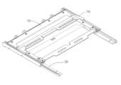
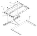
- FIG. 1is a perspective view of a state in which a sliding bar is installed in a sliding frame of a display device having a variable screen size according to the present invention.
- FIG. 2is a perspective view showing a state in which a sliding frame according to the present invention is combined with a fixed frame.
- FIG 3is a perspective view showing a state in which a sliding frame according to the present invention is coupled to a fixed frame.
- Figure 4is a perspective view showing a state in which the sliding control unit for controlling the movement of the sliding bar and sliding frame according to the present invention is installed.
- FIG. 5is a perspective view showing a sliding control unit of the present invention installed in a display device having a variable screen size according to the present invention.
- FIG. 6is a plan view showing a state in which the sliding bar and the sliding frame according to the present invention are all folded on the center bar of the fixed frame.
- FIG. 7is a plan view showing a state during which the sliding bar and the sliding frame according to the present invention are spread away from the central bar of the fixed frame.
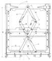
- FIG. 8is a plan view showing a state in which the sliding bar and the sliding frame according to the present invention are fully spread on the central bar of the fixed frame.
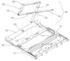
- FIG. 9is a perspective view illustrating a state in which a flexible display is installed to be connected to a sliding bar according to the present invention.
- FIG. 10is a perspective view showing a state in which a sliding control unit is installed according to another embodiment of the present invention.
- FIG. 11is a perspective view showing how an elastic part of a sliding control unit is assembled according to another embodiment of the present invention.
- FIG. 12is a partially enlarged view showing the operation of the elastic part of the sliding control unit according to another embodiment of the present invention.
- FIG. 13is a perspective view illustrating a state in which a pair of panel holders are installed on the front frame of the fixed frame of the present invention.
- FIG. 14is a perspective view showing a state in which the panel holder of the present invention is installed in the panel holder connection part.
- 15is a perspective view showing a state in which the panel holder connection part of the present invention is fixedly installed to the sliding frame of the present invention.
- FIG. 16is a perspective view showing a state in which the panel holder of the present invention is installed in the panel holder connection part installed in the front frame and the sliding frame of the fixed frame.
- FIG. 17is a perspective view showing a state in which a pair of central bars constituting a bi-directional sliding control unit according to the present invention are coupled.
- Figure 18is a perspective view showing a state in which a bi-directional sliding control unit for controlling the movement of the sliding bar and sliding frame respectively installed in the left and right directions according to the present invention is installed.
- FIG. 19is a perspective view showing a state in which a flexible display panel is installed in a state in which bi-directional sliding controllers are installed in the left and right sliding bars and the sliding frame according to the present invention.
- 20is a perspective view showing a state in which bi-directional sliding controllers are installed on the left and right sliding bars and the sliding frame according to the present invention and a flexible display panel is installed in a completely folded state.
- FIG. 21is a perspective view illustrating a state in which all flexible display panels are connected to the fully folded bi-directional sliding control unit shown in FIG. 20 .
- FIG. 22is a perspective view illustrating a state in which a side surface corresponding to a lower surface of a display device is covered by a cover in a state in which a flexible display panel is connected to a fully folded bi-directional sliding controller of a display device according to the present invention.
- FIG. 23is a perspective view showing a state in which a bi-directional sliding control unit exposed on a lower surface of a display device having a variable screen size according to the present invention is covered by a cover.
- FIG. 24is a perspective view showing a state in which a bidirectional sliding controller exposed on a lower surface of a display device having a variable screen size according to the present invention is covered by a cover.
- FIG. 1is a perspective view of a state in which a sliding bar is installed in a sliding frame of a display device having a variable screen size according to the present invention.
- a display device having a variable screen sizeincludes a U-shaped sliding frame 10, and the sliding frame 10 of the present invention includes the sliding frame 10 of the present invention A fixed bar 20 fixed to the sliding bar 16 and the sliding frame 10 moving along the left and right sides of the is installed.
- FIG. 2is a perspective view showing a state in which a sliding frame according to the present invention is combined with a fixed frame.
- 3is a perspective view showing a state in which a sliding frame according to the present invention is coupled to a fixed frame.
- the left and right side parts of the sliding frame 10 according to the present inventionare slid and fitted into the left and right side parts of the fixed frame 30 .
- the sliding frame 10 of the present inventionis configured to slide along the fixed frame 30 .
- Figure 4is a perspective view showing a state in which the sliding control unit for controlling the movement of the sliding bar and sliding frame according to the present invention is installed.
- 5is a perspective view showing a sliding control unit of the present invention installed in a display device having a variable screen size according to the present invention.
- the sliding control unit 40is installed at the center of the fixed frame 30 It is installed while connecting the fixed bar 20 and the sliding bar 16 of the bar 32 and the sliding frame 10, respectively.
- the sliding control unit 40 according to the present inventionincludes the sliding frame 10 moving along both side rails of the fixed frame 30 according to the present invention and the sliding moving along both side rails of the sliding frame 10 according to the present invention The moving distance and speed of each bar (16) are controlled at the same time.
- the central bar 32 according to the present inventionis installed to connect the ends of the side rails to each other in the fixing frame 30 of the present invention.
- the sliding control unit 40 of the present inventionis configured so that the middle points of each of the main bars 42 having the same length are connected in an X shape connected to each other to rotate (the first rotation point 44), respectively.
- each end of a pair of sub-bars 46 having a length of 1/2 of the length of the main bar 42is connected to rotate (the second rotation point 45), and , the other ends of the two sub-bars 46 are configured to be connected to the central portion of the central bar 32 (the third rotation point 48) so that they can rotate with each other.
- a first connection point 43is configured at the other end of each main bar 42 of the present invention, and each first connection point 43 is a rail composed of a groove in the longitudinal direction of the sliding bar 16 of the present invention Connected to the groove 116, the first connection point 43 of each main bar 42 is configured to slide left and right along the rail groove 116 of the sliding bar 16.
- the first connection point 43 of the present invention and the rail groove 116 of the sliding bar 16are connected to each other by rivets or the like.
- a second connection point 49is formed at the center between the first rotation point 44 and the second rotation point 45 of each main bar 42 of the present invention.
- the second connection point 49 of each main bar 42 of the present inventionis a rail groove 120 formed as a groove in the longitudinal direction of the fixing bar 20 of the sliding frame 10 of the present invention It is connected to and is configured to slide along the rail groove 120.
- connection point 49 and the rail groove 120 of the present inventionare connected to each other by rivets or the like.
- the third rotation point 48in which the pair of sub-bars 46 of the present invention are rotatably connected to each other, is rotatably connected to the center point 132 configured at the center of the center bar 32 installed in the fixed frame 30 do.
- the first connection point 43 and the second connection point 49 of each main bar 42 according to the present inventionare the rail groove 116 of the sliding bar 16 and the fixed bar of the sliding frame 10 ( 20), and the moving distance per unit time of the sliding bar 16 and the sliding frame 10 based on the center point 132 of the fixed frame 30 of the present invention is controlled by the sliding control unit 40.
- FIG. 6is a plan view showing a state in which the sliding bar and the sliding frame according to the present invention are all folded on the center bar of the fixed frame.
- the sliding frame 10is folded toward the center bar 32 of the present invention based on the center bar 32 of the fixed frame 30 of the present invention, in the sliding frame 10 of the present invention
- the sliding bar 16is also fully folded toward the center bar 32.
- the sliding control unit 40 of the present inventionis also completely folded.
- FIG. 7is a plan view showing a state during which the sliding bar and the sliding frame according to the present invention are spread away from the central bar of the fixed frame.
- the sliding frame 10 of the present inventionslides along the fixed frame 30 in a direction away from the central bar 32, and at the same time, the sliding bar 16 of the present invention slides along the sliding frame 10 It moves while sliding in the sliding frame 10 in the same direction as the moving direction in the fixed frame 30 .
- the distance that the sliding bar 16 of the present invention moves per unit time in the sliding frame 10is configured to be the same as the distance that the sliding frame 10 of the present invention moves per unit time in the fixed frame 30.
- the distance that the sliding bar 16 moves per unit time based on the center point 132 of the center bar 32 of the present inventionis 2 of the distance that the fixed bar 20 of the sliding frame 10 of the present invention moves per unit time It is made to double.
- FIG. 8is a plan view showing a state in which the sliding bar and the sliding frame according to the present invention are fully spread on the central bar of the fixed frame.
- the sliding control unit 40is fully extended from the center point 132, and the sliding bar 16 and the sliding frame 10 of the present invention connected to the sliding control unit 40 are connected to the center bar 32 ) is configured to expand as much as possible.
- the display device having a variable screen sizeconnects the central portions of the length of a pair of main bars 42 to rotate with each other, and 1/2 of the main bar 42 is attached to the end of each main bar 42.
- the flexible display panelis configured to spread wider by the sliding controller 40 connected to the sub-bar 46 having a length so as to be rotatable.
- FIG. 9is a perspective view illustrating a state in which a flexible display is installed to be connected to a sliding bar according to the present invention.
- the non-variable portion of the flexible display panel 4is fixedly attached to the upper surface of the display device having a variable screen size according to the present invention.
- the sliding bar 16 of the present invention located at the bottom of the display device of the present inventionis installed so that the end of the variable-size portion of the flexible display panel 4 is connected.
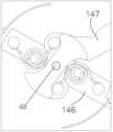
- FIG. 10is a perspective view showing a state in which a sliding control unit is installed according to another embodiment of the present invention.
- the sliding control unit 140according to another embodiment of the present invention is connected to the center bar 32 of the fixed frame 30, the fixed bar 20 and the sliding bar 16 of the sliding frame 10 It is connected.
- An elastic part 90is formed at a portion where the pair of sub-bars 146 and 147 of the present invention are connected to the center point 132 of the center bar 32.
- the elastic part 90 of the present inventionhas the role of allowing the sliding control part 140 to be unfolded and folded by the user up to a certain distance (critical point) by the elastic force, and to be automatically expanded or folded by the elastic force when the distance of the critical point is exceeded.
- FIG. 11is a perspective view showing how an elastic part of a sliding control unit is assembled according to another embodiment of the present invention.
- the central portions of the two main bars 42are rotatably connected to each other, and the ends of each main bar 42
- the sub-bars 146 and 147are rotatably connected to each other, and the other ends of the sub-bars are rotatably connected to each other.
- An elastic part 90configured to connect a pair of torsion springs 92 to each other is configured at a portion where the pair of sub-bars 146 and 147 of the present invention are connected to each other.
- FIG. 12is a partially enlarged view showing the operation of the elastic part of the sliding control unit according to another embodiment of the present invention.
- a pair of torsion springs 92 constituting the elastic part 90 of the present inventionconnects a pair of sub-bars 146 and 147 so that the pair of sub-bars 146 and 147 are folded or When unfolded, elastic force is applied.
- 13is a perspective view illustrating a state in which a pair of panel holders are installed on the front frame of the fixed frame of the present invention.
- 14is a perspective view showing a state in which the panel holder of the present invention is installed in the panel holder connection part.
- 15is a perspective view showing a state in which the panel holder connection part of the present invention is fixedly installed to the sliding frame of the present invention.
- 16is a perspective view showing a state in which the panel holder of the present invention is installed in the panel holder connection part installed in the front frame and the sliding frame of the fixed frame.
- the ends of a pair of panel holders 75are connected to the central portion of the front portion 35 of the fixing frame 30 according to the present invention.
- the other end of the panel holder 75 of the present inventionis inserted into the two sliding grooves 68 of the panel holder connection part 66 installed on the lower surface of the front part 15 of the sliding frame 10, respectively.
- a pair of panel holders 75 of the present inventionsupport the unfolded state of the flexible display panel 4 of the present invention when the flexible display panel 4 having a plurality of joints 6 installed on the lower surface slides and operates. play a role in making
- FIG. 17is a perspective view showing a state in which a pair of central bars constituting a bi-directional sliding control unit according to the present invention are coupled.
- central portions of a pair of central bars 82 and 83 located at the center of the bi-directional sliding control unit 240 according to the present inventionare connected to rotate with each other.
- the pair of center bars 82 of the present inventionare connected to each other by a pair of torsion springs 92, and when the pair of center bars 82 and 83 are folded or unfolded, an elastic force is applied, and a semi-automatic bi-directional sliding control unit ( 240) is configured to be unfolded or folded.
- Figure 18is a perspective view showing a state in which a bi-directional sliding control unit for controlling the movement of the sliding bar and sliding frame respectively installed in the left and right directions according to the present invention is installed.
- 19is a perspective view showing a state in which a flexible display panel is installed in a state in which bi-directional sliding controllers are installed in the left and right sliding bars and the sliding frame according to the present invention.
- a sliding hinge unitfor implementing a bi-directional rollable display device in which a display panel slides left and right simultaneously according to another embodiment of the present invention is fixed to a pair facing each other according to the present invention.
- the frames 30are connected to each other by the central bar 32, and the sliding frame 10 of the present invention is slid and installed on both side rails of the left and right fixed frames 30, and the bi-directional sliding control unit 240 is left and right It is installed while connecting each of the fixed bars 20 and each of the sliding bars 16 of the central bar 32 and the sliding frames 10 on the left and right, respectively, connecting the fixed frame 30 of the fixed frame.
- the bidirectional sliding control unit 240is each sliding frame 10 moving along both side rails of the left and right fixed frames 30 according to the present invention and both sides of each sliding frame 10 of the present invention The moving distance and speed of each sliding bar 16 moving along the side rail are simultaneously controlled.
- the central bar 32 according to the present inventionis installed to connect the ends of the side rails of the left and right fixed frames 30 of the present invention to each other.
- the bidirectional sliding control unit 240 of the present inventionincludes two pairs of main bars 42 (first rotation point 44) connected to each other in an X shape and a pair of central bars 82 connected to each other in an X shape. , 83) (the third rotation point 48) are configured to be connected to each other. (2nd turning point (45))
- Each pair of main bars 42 according to the present inventionare connected to each other so that they can rotate in the shape of an X, and a pair of central bars 82 and 83 at the center of the bi-directional sliding control unit 240 of the present invention are mutually X Located in a state connected to rotate in a letter shape, one end of each pair of main bars 42 connected in an X shape is connected to both ends of the central bars 82 and 82, respectively. (2nd turning point (45))
- the second rotation point 48 to which the pair of center bars 82 and 83, which become the second rotation point 48, are connected in an X shapeis connected to the middle part 132 of the center bar 32 of the present invention It is composed so that
- a first connection point 43is configured at the other end of each main bar 42 of the present invention, and each first connection point 43 is a rail groove configured as a groove in the longitudinal direction of the sliding bar 16 of the present invention 116, the first connection point 43 of each main bar 42 is configured to slide left and right along the rail groove 116 of the sliding bar 16.
- the first connection point 43 of the present invention and the rail groove 116 of the sliding bar 16are connected to each other by rivets or the like.
- a second connection point 49is formed at the center of the first rotation point 44 and the second rotation point 45 of each main bar 42 of the present invention.
- each main bar 42 of the present inventionis connected to the rail groove 120 formed as a groove in the fixing bar 20 of the sliding frame 10 of the present invention, and the rail groove 120 It is configured to slide along.
- connection point 49 and the rail groove 120 of the present inventionare connected to each other by rivets or the like.
- the third rotation point 48in which the pair of sub-bars 46 of the present invention are rotatably connected to each other, is rotatably connected to the center point 132 configured at the center of the center bar 32 installed in the fixed frame 30 do.
- the first connection point 43 and the second connection point 49 of each main bar 42 according to the present inventionare the rail groove 116 of the sliding bar 16 and the fixed bar of the sliding frame 10 ( 20), and the movement distance per unit time of the sliding bar 16 and the sliding frame 10 based on the central point 132 of the fixed frame 30 of the present invention is controlled by the bidirectional sliding control unit 240. .
- FIG. 20is a perspective view showing a state in which bi-directional sliding controllers are installed on the left and right sliding bars and the sliding frame according to the present invention and a flexible display panel is installed in a completely folded state.
- FIG. 21is a perspective view illustrating a state in which all flexible display panels are connected to the fully folded bi-directional sliding control unit shown in FIG. 20 .
- the non-sliding part of the flexible display panel 4is fixedly installed on the upper surface of the display device according to the present invention in a state in which the bidirectional sliding control unit 240 according to the present invention is completely folded. .
- Both ends of the flexible display panel 4 of the present inventionare fixedly attached to each sliding bar 16 .
- 22is a perspective view illustrating a state in which a side surface corresponding to a lower surface of a display device is covered by a cover in a state in which a flexible display panel is connected to a fully folded bi-directional sliding controller of a display device according to the present invention.
- 23is a perspective view showing a state in which a bi-directional sliding control unit exposed on a lower surface of a display device having a variable screen size according to the present invention is covered by a cover.
- 24is a perspective view showing a state in which a bidirectional sliding controller exposed on a lower surface of a display device having a variable screen size according to the present invention is covered by a cover.
- the flexible display panel 4 exposed on the lower surface of the display device according to the present inventionis covered by a partial cover 8, and the display according to the present invention is covered by a body cover 9
- the deviceis assembled so that the lower surface is covered.
Landscapes
- Engineering & Computer Science (AREA)
- Theoretical Computer Science (AREA)
- Physics & Mathematics (AREA)
- General Physics & Mathematics (AREA)
- General Engineering & Computer Science (AREA)
- Computer Hardware Design (AREA)
- Human Computer Interaction (AREA)
- Mathematical Physics (AREA)
- Mechanical Engineering (AREA)
- Devices For Indicating Variable Information By Combining Individual Elements (AREA)
Abstract
Description
Translated fromKorean본 발명은 화면의 크기가 가변하는 디스플레이장치에 관한 것으로, 더욱 자세히 설명하면, 디스플레이화면이 롤링하면서 넓혀지거나 좁혀지는 롤러블 디스플레이 장치의 내부에 메인바와 서브바로 구성선 변형된 X 바가 설치되어 넓은 디스플레이 화면을 구현하는 화면의 크기가 가변되는 디스플레이장치에 관한 것이다.The present invention relates to a display device having a variable screen size, and more specifically, in a rollable display device in which a display screen is widened or narrowed while rolling, an X bar deformed by a construction line of a main bar and a sub bar is installed to display a wide display. It relates to a display device in which the size of a screen that implements a screen is variable.
이동 단말기는 다양한 기능을 수행할 수 있도록 구성될 수 있다. 그러한 다양한 기능들의 예로 데이터 및 음성통신 기능, 카메라를 통해 사진이나 동영상을 촬영하는 기능, 음성 저장 기능, 스피커 시스템을 통한 음악 파일의 재생기능, 이미지나 비디오의 디스플레이 기능 등이 있다.A mobile terminal may be configured to perform various functions. Examples of such various functions include a data and voice communication function, a function of taking pictures or videos through a camera, a function of recording voice, a function of playing music files through a speaker system, and a function of displaying images or videos.
일부 이동 단말기는 게임을 실행할 수 있는 추가적 기능을 포함하고, 다른 일부 이동 단말기는 멀티미디어 기기로서 구현되기도 한다. 더욱이 최근의 이동단말기는 방송이나 멀티캐스트(multicast) 신호를 수신하여 비디오나 텔레비전 프로그램을 시청할 수 있다.Some mobile terminals include an additional function for playing games, and some other mobile terminals are implemented as multimedia devices. Moreover, recent mobile terminals can watch video or television programs by receiving broadcast or multicast signals.
상기 기능에 부가하여 현재 이동 단말기의 기능을 지지하고 증대하기 위한 노력들이 계속되고 있다. 상술한 노력은 이동 단말기를 형성하는 구조적인 구성요소의 변화 및 개량뿐만 아니라 소프트웨어나 하드웨어의 추가 및 개량도 포함한다.Efforts are ongoing to support and augment the capabilities of current mobile terminals in addition to the above capabilities. The above efforts include not only changes and improvements in structural elements forming the mobile terminal, but also addition and improvement of software or hardware.
일반적으로 이동 단말기에서 디스플레이 모듈은 이동 단말기에서 처리되는 정보를 표시한다. 예를 들어 이동 단말기가 통화 모드인 경우 통화와 관련된 UI(User Interface) 또는 GUI(Graphic User Interface)를 표시한다.In general, a display module in a mobile terminal displays information processed in the mobile terminal. For example, when the mobile terminal is in a call mode, a UI (User Interface) or GUI (Graphic User Interface) related to a call is displayed.
그리고 이동 단말기가 화상 통화 모드 또는 촬영 모드인 경우 촬영 또는/및 수신된 영상 또는 UI, GUI 를 표시한다. 상기 디스플레이 모듈은 액정 디스플레이 (liquid crystal display), 박막 트랜지스터 액정 디스플레이 (thin film transistor-liquid crystal display), 유기 발광 다이오드(organic light-emitting diode), 플렉시블 디스플레이(flexible display), 3차원 디스플레이(3D display) 등으로 구성될 수 있다.In addition, when the mobile terminal is in a video call mode or a shooting mode, a photographed or/and received video, UI, or GUI is displayed. The display module includes a liquid crystal display, a thin film transistor-liquid crystal display, an organic light-emitting diode, a flexible display, and a 3D display. ) and the like.
그 중에서 플렉시블 디스플레이(flexible display)(또는 플렉시블 LCD)는 모양을 마음대로 변형할 수 있다는 장점 때문에 현재 그 연구가 본격화되고 있다. 하지만, 현재 공상영화에서 보여주는 것처럼 완전히 종이와 같은 디스플레이를 두루마리처럼 가지고 다니기까지는 앞으로 많은 시간이 걸릴 것으로 보여진다.Among them, a flexible display (or flexible LCD) is currently being researched in earnest because of the advantage of being able to change its shape at will. However, it seems that it will take a lot of time in the future to carry a completely paper-like display like a scroll, as shown in current science fiction films.
따라서, 플렉시블 디스플레이의 개발이 진행되어 사용이 본격적으로 활성화되기 전까지는 과도기적 형태가 많이 사용될 것이며 이 형태는 현재의 단말기 구조와 크게 다르지 않을 것이다. 또한, 현재 개발되고 있는 플렉시블 디스플레이가 이동 단말기에 사용될 때 그 사용 형태 및 그 보호방법에 대하여 기술할 필요성이 대두된다.Therefore, the transitional form will be used a lot until the flexible display is developed and used in earnest, and this form will not be significantly different from the current terminal structure. In addition, when a flexible display currently being developed is used in a mobile terminal, there is a need to describe its use form and its protection method.
본 발명에 따른 연성디스플레이 패널이 설치되는 모바일 통신장치용 힌지구조와 유사한 특허문헌으로는 공개번호 10-2015-0096827, (발명의 명칭 힌지장치 및 이를 구비하는 폴더블 디스플레이 장치) 가 있다.Patent documents similar to the hinge structure for a mobile communication device in which a flexible display panel according to the present invention is installed include Publication No. 10-2015-0096827, (Invention Title Hinge Device and Foldable Display Device Having the Same).
본 발명은 디스플레이화면이 롤링하면서 넓혀지거나 좁혀지는 롤러블 디스플레이 장치의 내부에 메인바와 서브바로 구성선 변형된 X 바가 설치되어 넓은 디스플레이 화면을 구현하는 화면의 크기가 가변되는 디스플레이장치를 제공하는 것을 목적으로 한다.An object of the present invention is to provide a display device having a variable screen size that implements a wide display screen by installing a deformed X bar in a construction line of a main bar and a sub bar inside a rollable display device in which a display screen is widened or narrowed while rolling. to be
상기의 목적을 달성하기 위하여, 본 발명에 따른 화면의 크기가 가변하는 디스플레이장치는 고정프레임; 상기 고정프레임을 따라 슬라이딩하면서 움직이는 슬라이딩프레임; 및 상기 고정프레임과 상기 슬라이딩 프레임에 연결되어 설치되는 상기 슬라이딩프레임이 상기 고정프레임을 따라 슬라이딩하는 거리를 제어하는 슬라이딩 제어부를 포함하고,In order to achieve the above object, a display device having a variable screen size according to the present invention includes a fixed frame; a sliding frame moving while sliding along the fixed frame; And a sliding control unit for controlling a sliding distance of the sliding frame connected to the fixed frame and the sliding frame and installed along the fixed frame,
상기 슬라이딩제어부는 한쌍의 메인바의 각각의 중심이 서로 회전하도록 연결된 X 바와, 상기 각각의 메인바의 일단부와 회전하도록 각각 연결되어 제 2 회전점을 구성하고, 다단부는 상기 고정프레임의 중심바와 회전하도록 연결되어 제 3 회전점을 구성하고, 상기 메인바의 1/2 의 길이를 가지는 서브바로 이루어진 것을 특징으로 하고,The sliding control unit is connected so that the center of each of the pair of main bars rotates with each other, and one end of each of the main bars is connected to each other to form a second rotation point, and the multiple ends are connected to the center bar of the fixed frame. It is connected to rotate and constitutes a third rotation point, characterized in that it consists of a sub bar having a length of 1/2 of the main bar,
상기 슬라이딩 프레임은 상기 슬라이딩 프레임에서 슬라이딩하는 슬라이딩바 와 고정되어 있는 고정바를 포함하고,The sliding frame includes a sliding bar sliding on the sliding frame and a fixed bar,
상기 슬라이딩제어부를 구성하는 상기 각각의 메인바의 타단부는 상기 슬라이딩바에 연결되고, 상기 각각의 메인바가 X 자로 서로 연결된 제 1 회전점과 상기 제 2 회전점 의 중심부분은 상기 고정바와 연결되고,The other end of each of the main bars constituting the sliding control unit is connected to the sliding bar, and the center portion of the first rotation point and the second rotation point connected to each other in the shape of an X of each main bar are connected to the fixed bar,
상기 슬라이딩제어부는 상기 고정프레임의 양쪽 측면레일을 따라 이동하는 상기 슬라이딩프레임과 상기 슬라이딩 프레임을 따라 이동하는 슬라이딩바의 각각의 이동거리와 속도를 동시에 제어하는 것을 특징으로 하고,The sliding control unit simultaneously controls the moving distance and speed of the sliding frame moving along both side rails of the fixed frame and the sliding bar moving along the sliding frame,
상기 한쌍의 서브바가 상기 고정프레임의 중심바에 서로 연결되어 제 3 회전점에 서로 연결된 상태에서 상기 각각의 서브바에는 탄성장치가 연결되어 상기 각각의 서브바에 서로 반대방향으로 탄성력이 가해지는 것을 특징으로 하고,In a state in which the pair of sub-bars are connected to the center bar of the fixing frame and connected to each other at the third rotation point, an elastic device is connected to each of the sub-bars, so that elastic force is applied to each of the sub-bars in opposite directions. do,
상기 슬라이딩프레임과 상기 고정프레임 사이에는 플렉서블디스플레이 패널의 처짐을 방지하는 패널거치대가 설치되는 것을 특징으로 하고,It is characterized in that a panel holder is installed between the sliding frame and the fixed frame to prevent sagging of the flexible display panel.
다른 실시예에 따른 화면의 크기가 가변되는 디스플레이장치는, 좌우 한쌍의 고정프레임; 상기 좌우 한쌍의 고정프레임을 고정되게 연결하는 중심바;A display device having a variable screen size according to another embodiment includes a pair of left and right fixed frames; a central bar fixedly connecting the pair of left and right fixing frames;
상기 각각의 고정프레임을 따라 슬라이딩하면서 움직이는 각각의 슬라이딩프레임; 및 상기 각각의 고정프레임과 상기 각각의 슬라이딩 프레임에 연결되게 설치되는 상기 각각의 슬라이딩프레임이 상기 각각의 고정프레임을 따라 상기 중심바의 중심부를 중심으로 좌우로 슬라이딩하는 거리를 제어하는 양방향 슬라이딩 제어부를 포함하고, 상기 양방향 슬라이딩제어부는 상기 중심바에 X 자모양으로 연결된 중심이 연결된 중앙바와 상기 X 자 모양으로 연결된 중앙바의 좌우 일단부와 X 자 모양으로 연결된 메인바가 연결되어 제 2 회전점을 구성하는 것을 특징으로 하고,Each sliding frame moving while sliding along each of the fixed frames; and a bi-directional sliding controller for controlling a distance at which each of the sliding frames installed to be connected to each of the fixed frames and each of the sliding frames slide left and right around the center of the center bar along each of the fixed frames. The two-way sliding control unit is connected to the center bar connected in an X shape to the center bar and the left and right ends of the center bar connected in an X shape and the main bar connected in an X shape to form a second rotation point characterized in that,
상기 슬라이딩 프레임은 상기 슬라이딩 프레임에서 슬라이딩하는 슬라이딩바 와 고정되어 있는 고정바를 포함하고, 상기 양방향 슬라이딩제어부를 구성하는 상기 각각의 메인바의 타단부는 상기 슬라이딩바에 연결되고,The sliding frame includes a sliding bar sliding in the sliding frame and a fixed bar, and the other end of each of the main bars constituting the bi-directional sliding control unit is connected to the sliding bar,
상기 각각의 메인바가 X 자로 서로 연결된 각각의 제 1 회전점과 상기 제 2 회전점의 중심부분은 상기 각각의 고정바와 연결되고,The center portions of each of the first rotation points and the second rotation points of each of the main bars connected to each other in the shape of an X are connected to the respective fixing bars,
상기 양방향 슬라이딩제어부는 상기 좌우 고정프레임의 양쪽 측면레일을 따라 이동하는 상기 각각의 슬라이딩프레임과 상기 슬라이딩 프레임을 따라 이동하는 슬라이딩바의 각각의 이동거리와 속도를 동시에 제어하는 것을 특징으로 하고,The bi-directional sliding control unit simultaneously controls the movement distance and speed of each of the sliding frames moving along both side rails of the left and right fixed frames and the sliding bar moving along the sliding frame,
상기 한쌍의 중앙바가 서로 연결된 중심이 상기 고정프레임의 중심바에 서로 연결되어 제 3 회전점을 구성하고 서로 연결된 상태에서 상기 각각의 중앙바에는 탄성장치가 연결되어 상기 각각의 중앙바에 서로 반대방향으로 탄성력이 가해지는 것을 특징으로 하고,The center of the pair of center bars connected to each other is connected to the center bar of the fixing frame to form a third rotation point, and in a state where they are connected to each other, an elastic device is connected to each center bar to provide elastic force in opposite directions to each center bar. Characterized in that this is applied,
상기 각각의 슬라이딩프레임과 상기 고정프레임 사이에는 플렉서블디스플레이 패널의 처짐을 방지하는 패널거치대가 설치되는 것을 특징으로 한다.It is characterized in that a panel holder for preventing sagging of the flexible display panel is installed between each of the sliding frame and the fixed frame.
본 발명에 따른 화면의 크기가 가변하는 디스플레이장치에 의하면, 디스플레이화면이 롤링하면서 넓혀지거나 좁혀지는 롤러블 디스플레이 장치의 내부에 메인바와 서브바로 구성된 변형된 X 바가 설치되어 넓은 디스플레이 화면을 구현하는 효과가 있다.According to the display device having a variable screen size according to the present invention, a deformed X bar composed of a main bar and a sub bar is installed inside a rollable display device in which the display screen is widened or narrowed while rolling, so that a wide display screen is realized. there is.
디스플레이장치의 내부에 1개의 X 바 (bar) 와 X 바의 길이의 1/2 에 해당하는 서브바를 함께 구성하여 1 개의 X 바로 힌지가 구성되는 경우보다 화면의 크기가 더 넓이질 수 있고, 2 개의 X 바로 구성되는 경우보다 제품을 신뢰성을 높일 수 있는 효과가 있다. 2 개의 X 바로 힌지가 구성이 되면 디스플레이 제품이 전체적인 무게를 감당하지 못하고 프레임자체가 기울어지는 문제점이 발생하였으나, 1 과 1/2 의 바(bar) 로 구성된 힌지의 사용으로 디스플레이 패널을 더 넓게 사용하면서 제품의 전부 펼쳐진 상태에서도 펼쳐진 부분의 충분히 일직선으로 지탱하는 효과가 달성이 된다.By configuring one X bar inside the display device and a sub bar corresponding to 1/2 the length of the X bar, the screen size can be wider than in the case of a hinge consisting of one X bar, 2 There is an effect of increasing the reliability of the product compared to the case of consisting of two X bars. When the hinge is composed of 2 X bars, the display product cannot handle the overall weight and the frame itself has a problem of tilting. Even in the fully unfolded state of the product, the effect of supporting the unfolded part in a straight line is achieved.
그리고, 본 발명의 중심바를 중심으로 좌우로 1과 1/2바 (bar) 로 구성하게 하여 더 넓은 패널과 디스플레이 패널이 전부 펼쳐진 상태에서도 슬라이딩프레임이 고정프레임상에서 이격되거나 흔들림이 없이 지탱하는데 문제가 없는 장점이 있다.In addition, since the center bar of the present invention is composed of 1 and 1/2 bars on the left and right, there is a problem in supporting the sliding frame without being separated from or shaken on the fixed frame even when the wider panel and display panel are fully unfolded There are no advantages.
도 1 은 본 발명에 따른 화면의 크기가 가변하는 디스플레이장치의 슬라이딩프레임에 슬라이딩바가 설치된 모습의 사시도이다.1 is a perspective view of a state in which a sliding bar is installed in a sliding frame of a display device having a variable screen size according to the present invention.
도 2 는 본 발명에 따른 슬라이딩 프레임이 고정프레임과 결합하는 모습을 도시한 사시도이다.2 is a perspective view showing a state in which a sliding frame according to the present invention is combined with a fixed frame.
도 3 은 본 발명에 따른 슬라이딩 프레임이 고정프레임에 결합된 모습을 도시한 사시도이다.3 is a perspective view showing a state in which a sliding frame according to the present invention is coupled to a fixed frame.
도 4 는 본 발명에 따른 슬라이딩바 및 슬라이딩프레임의 이동을 제어하는 슬라이딩 제어부가 설치되는 모습을 도시한 사시도이다.Figure 4 is a perspective view showing a state in which the sliding control unit for controlling the movement of the sliding bar and sliding frame according to the present invention is installed.
도 5 는 본 발명에 따른 화면의 크기가 가변하는 디스플레이장치에 본 발명의 슬라이딩제어부가 설치된 모습을 도시한 사시도이다.5 is a perspective view showing a sliding control unit of the present invention installed in a display device having a variable screen size according to the present invention.
도 6 은 본 발명에 따른 슬라이딩바 및 슬라이딩프레임이 고정프레임의 중심바에 전부 접혀져 있는 모습을 도시한 평면도이다.6 is a plan view showing a state in which the sliding bar and the sliding frame according to the present invention are all folded on the center bar of the fixed frame.
도 7 은 본 발명에 따른 슬라이딩바 및 슬라이딩프레임이 고정프레임의 중심바에 멀어지게 펼쳐지는 도중의 모습을 도시한 평면도이다.7 is a plan view showing a state during which the sliding bar and the sliding frame according to the present invention are spread away from the central bar of the fixed frame.
도 8 은 본 발명에 따른 슬라이딩바 및 슬라이딩프레임이 고정프레임의 중심바에 전부 펼쳐져 있는 모습을 도시한 평면도이다.8 is a plan view showing a state in which the sliding bar and the sliding frame according to the present invention are fully spread on the central bar of the fixed frame.
도 9 는 본 발명에 따른 슬라이딩바에 플렉서블 디스플레이가 연결되게 설치된 모습을 도시한 사시도이다.9 is a perspective view illustrating a state in which a flexible display is installed to be connected to a sliding bar according to the present invention.
도 10 은 본 발명의 다른 실시예에 따른 슬라이딩제어부가 설치된 모습을 도시한 사시도이다.10 is a perspective view showing a state in which a sliding control unit is installed according to another embodiment of the present invention.
도 11 은 본 발명의 다른 실시예에 따른 슬라이딩제어부의 탄성부가 조립되는 모습을 도시한 사시도이다.11 is a perspective view showing how an elastic part of a sliding control unit is assembled according to another embodiment of the present invention.
도 12 는 본 발명의 다른 실시예에 따른 슬라이딩제어부의 탄성부가 동작하는 모습을 도시한 부분확대도이다.12 is a partially enlarged view showing the operation of the elastic part of the sliding control unit according to another embodiment of the present invention.
도 13 은 본 발명의 고정프레임의 정면프레임에 한쌍의 패널거치대가 설치되는 모습을 도시한 사시도이다.13 is a perspective view illustrating a state in which a pair of panel holders are installed on the front frame of the fixed frame of the present invention.
도 14 는 본 발명의 패널거치대가 패널거치대 연결부에 설치되는 모습을 도시한 사시도이다.14 is a perspective view showing a state in which the panel holder of the present invention is installed in the panel holder connection part.
도 15 는 본 발명의 패널거치대 연결부가 본 발명의 슬라이딩프레임에 고정되게 설치되는 모습을 도시한 사시도이다.15 is a perspective view showing a state in which the panel holder connection part of the present invention is fixedly installed to the sliding frame of the present invention.
도 16 은 본 발명의 패널거치대가 고정프레임의 정면프레임과 슬라이딩프레임에 설치된 패널거치대 연결부에 설치된 모습을 도시한 사시도이다.16 is a perspective view showing a state in which the panel holder of the present invention is installed in the panel holder connection part installed in the front frame and the sliding frame of the fixed frame.
도 17 은 본 발명에 따른 양방향 슬라이딩 제어부를 구성하는 한쌍의 중앙바가 결합하는 모습을 도시한 사시도이다.17 is a perspective view showing a state in which a pair of central bars constituting a bi-directional sliding control unit according to the present invention are coupled.
도 18 본 발명에 따른 좌우 방향으로 각각 설치된 슬라이딩바 및 슬라이딩프레임의 이동을 제어하는 양방향 슬라이딩 제어부가 설치되는 모습을 도시한 사시도이다. Figure 18 is a perspective view showing a state in which a bi-directional sliding control unit for controlling the movement of the sliding bar and sliding frame respectively installed in the left and right directions according to the present invention is installed.
도 19 는 본 발명에 따른 좌우 슬라이딩바 및 슬라이딩 프레임에 양방향 슬라이딩 제어부가 설치된 상태에서 플렉서블 디스플레이 패널이 설치된 모습을 도시한 사시도이다.19 is a perspective view showing a state in which a flexible display panel is installed in a state in which bi-directional sliding controllers are installed in the left and right sliding bars and the sliding frame according to the present invention.
도 20 은 본 발명에 따른 좌우 슬라이딩바 및 슬라이딩 프레임에 양방향 슬라이딩 제어부가 설치되고 전부 접혀진 상태에서 플렉서블 디스플레이 패널이 설치되는 모습을 도시한 사시도이다.20 is a perspective view showing a state in which bi-directional sliding controllers are installed on the left and right sliding bars and the sliding frame according to the present invention and a flexible display panel is installed in a completely folded state.
도 21 은 도 20 에 도시된 전부 접혀진 양방향 슬라이딩 제어부에 플렉서블 디스플레이 패널이 전부 연결된 상태를 도시한 사시도이다.FIG. 21 is a perspective view illustrating a state in which all flexible display panels are connected to the fully folded bi-directional sliding control unit shown in FIG. 20 .
도 22 는 본 발명에 따른 디스플레이장치의 전부 접혀진 양방향 슬라이딩 제어부에 플렉서블 디스플레이 패널이 연결된 상태에서 디스플레이장치의 하부면과 대응하는 측면을 커버에 의해 덮는 모습을 도시한 사시도이다.22 is a perspective view illustrating a state in which a side surface corresponding to a lower surface of a display device is covered by a cover in a state in which a flexible display panel is connected to a fully folded bi-directional sliding controller of a display device according to the present invention.
도 23 은 본 발명에 따른 화면의 크기가 가변하는 디스플레이장치의 하부면에 노출된 양방향 슬라이딩 제어부를 커버에 의해 덮혀지는 모습을 도시한 사시도이다.23 is a perspective view showing a state in which a bi-directional sliding control unit exposed on a lower surface of a display device having a variable screen size according to the present invention is covered by a cover.
도 24 는 본 발명에 따른 화면의 크기가 가변하는 디스플레이장치의 하부면에 노출된 양방향 슬라이딩 제어부가 커버에 의해 덮혀진 모습을 도시한 사시도이다.24 is a perspective view showing a state in which a bidirectional sliding controller exposed on a lower surface of a display device having a variable screen size according to the present invention is covered by a cover.
도 1 은 본 발명에 따른 화면의 크기가 가변하는 디스플레이장치의 슬라이딩프레임에 슬라이딩바가 설치된 모습의 사시도이다.1 is a perspective view of a state in which a sliding bar is installed in a sliding frame of a display device having a variable screen size according to the present invention.
도 1 을 참조하면, 본 발명에 따른 화면의 크기가 가변하는 디스플레이장치는, ㄷ 자 모양의 슬라이딩프레임 (10) 을 포함하고, 본 발명의 슬라이딩프레임 (10) 에는 본 발명의 슬라이딩프레임 (10) 의 좌우측면을 따라 이동하는 슬라이딩바 (16) 와 슬라이딩프레임 (10) 에 고정되는 고정바 (20) 가 설치된다.Referring to FIG. 1, a display device having a variable screen size according to the present invention includes a U-shaped sliding
도 2 는 본 발명에 따른 슬라이딩 프레임이 고정프레임과 결합하는 모습을 도시한 사시도이다. 도 3 은 본 발명에 따른 슬라이딩 프레임이 고정프레임에 결합된 모습을 도시한 사시도이다.2 is a perspective view showing a state in which a sliding frame according to the present invention is combined with a fixed frame. 3 is a perspective view showing a state in which a sliding frame according to the present invention is coupled to a fixed frame.
도 2 및 도 3 을 참조하면, 본 발명에 따른 슬라이딩프레임 (10) 의 좌우측면부가 고정프레임 (30) 의 좌우측면부에 슬라이딩하면서 끼워진다.Referring to FIGS. 2 and 3 , the left and right side parts of the sliding
본 발명의 슬라이딩프레임 (10) 은 고정프레임 (30) 을 따라 슬라이딩하도록 구성된다.The sliding
도 4 는 본 발명에 따른 슬라이딩바 및 슬라이딩프레임의 이동을 제어하는 슬라이딩 제어부가 설치되는 모습을 도시한 사시도이다. 도 5 는 본 발명에 따른 화면의 크기가 가변하는 디스플레이장치에 본 발명의 슬라이딩제어부가 설치된 모습을 도시한 사시도이다.Figure 4 is a perspective view showing a state in which the sliding control unit for controlling the movement of the sliding bar and sliding frame according to the present invention is installed. 5 is a perspective view showing a sliding control unit of the present invention installed in a display device having a variable screen size according to the present invention.
도 4 및 도 5 를 참조하면, 본 발명에 따른 고정프레임 (30) 의 양쪽 측면레일에 본 발명의 슬라이딩프레임 (10) 이 슬라이딩되어 설치된 상태에서 슬라이딩제어부 (40) 가 고정프레임 (30) 의 중심바 (32) 와 슬라이딩프레임 (10) 의 고정바 (20) 및 슬라이딩바 (16) 를 각각 연결하면서 설치된다.4 and 5, in a state in which the sliding
본 발명에 따른 슬라이딩제어부 (40) 는 본 발명에 따른 고정프레임 (30) 의 양쪽 측면레일을 따라 이동하는 슬라이딩프레임 (10) 과 본 발명의 슬라이딩 프레임 (10) 의 양쪽 측면레일을 따라 이동하는 슬라이딩바 (16) 각각의 이동거리와 속도를 동시에 제어한다.The sliding
본 발명에 따른 중심바 (32) 는 본 발명의 고정프레임 (30) 에서 측면레일의 단부를 서로 연결하게 설치된다.The
본 발명의 슬라이딩 제어부 (40) 는 2 개의 동일한 길이를 가지는 각각의 메인바 (42) 의 정 가운데 지점이 서로 회전하도록 연결된 X 자 모양으로 연결되게 구성 (제 1 회전점 (44)) 되고, 각각의 메인바 (42) 의 한쪽 단부에는 메인바 (42) 의 길이의 1/2 의 길이를 가지는 한쌍의 서브바 (46) 의 각각의 일단부가 회전하도록 연결 (제 2 회전점 (45)) 되고, 2 개의 서브바 (46) 의 다른쪽 단부는 서로 회전할 수 있도록 함께 중심바 (32) 의 가운데 부분에 연결 (제 3 회전점 (48)) 되게 구성된다.The sliding
본 발명의 각각의 메인바 (42) 의 다른 쪽 단부에는 제 1 연결점 (43) 이 구성되고, 각각의 제 1 연결점 (43) 은 본 발명의 슬라이딩바 (16) 의 길이방향으로 홈으로 구성된 레일홈 (116) 과 연결되어 각각의 메인바 (42) 의 제 1 연결점 (43) 이 슬라이딩바 (16) 의 레일홈 (116) 을 따라 좌우로 슬라이딩하게 구성된다.A
본 발명의 제 1 연결점 (43) 과 슬라이딩바 (16) 의 레일홈 (116) 은 서로 리벳 등에 의해 연결된다.The
본 발명의 각각의 메인바 (42) 의 제 1 회전점 (44) 과 제 2 회전점 (45) 사이의 중심에는 제 2 연결점 (49) 이 구성된다.A
본 발명의 각각의 메인바 (42) 의 제 2 연결점 (49) 은 본 발명의 슬라이딩프레임 (10) 의 고정바 (20) 에 고정바 (20) 의 길이방향으로 홈으로 형성된 레일홈 (120) 에 연결되고, 레일홈 (120) 을 따라 슬라이딩하게 구성된다.The
본 발명의 제 2 연결점 (49) 과 레일홈 (120) 은 리벳 등에 의해 서로 연결된다.The
본 발명의 한쌍의 서브바 (46) 가 서로 회전가능하도록 연결된 제 3 회전점 (48) 은 고정프레임 (30) 에 설치된 중심바 (32) 의 중심에 구성되는 중심점 (132) 과 회전가능하도록 연결된다.The
본 발명에 따른 각각의 메인바 (42) 의 제 1 연결점 (43) 과 제 2 연결점 (49) 은 본 발명의 슬라이딩바 (16) 의 레일홈 (116) 및 슬라이딩 프레임 (10) 의 고정바 (20) 와 연결되고, 본 발명의 고정프레임 (30) 의 중심점 (132) 을 기준으로 슬라이딩바 (16) 와 슬라이딩프레임 (10) 의 단위시간단 이동거리가 슬라이딩제어부 (40) 에 의해 제어된다.The
도 6 은 본 발명에 따른 슬라이딩바 및 슬라이딩프레임이 고정프레임의 중심바에 전부 접혀져 있는 모습을 도시한 평면도이다.6 is a plan view showing a state in which the sliding bar and the sliding frame according to the present invention are all folded on the center bar of the fixed frame.
도 6 을 참조하면, 본 발명의 고정프레임 (30) 의 중심바 (32) 를 기준으로 본 발명의 중심바 (32) 쪽으로 슬라이딩프레임 (10) 이 접혀지고, 본 발명의 슬라이딩프레임 (10) 에서 슬라이딩바 (16) 도 중심바 (32) 쪽으로 전부 접혀진다.6, the sliding
본 발명의 슬라이딩제어부 (40) 도 완전히 접혀진 상태가 된다.The sliding
도 7 은 본 발명에 따른 슬라이딩바 및 슬라이딩프레임이 고정프레임의 중심바에 멀어지게 펼쳐지는 도중의 모습을 도시한 평면도이다.7 is a plan view showing a state during which the sliding bar and the sliding frame according to the present invention are spread away from the central bar of the fixed frame.
도 7 을 참조하면, 본 발명의 슬라이딩프레임 (10) 이 중심바 (32) 에서 멀어지는 방향으로 고정프레임 (30) 을 따라 슬라이딩하고, 동시에 본 발명의 슬라이딩바 (16) 가, 슬라이딩프레임 (10) 이 고정프레임 (30) 에서 이동하는 방향과 동일한 방향으로 슬라이딩프레임 (10) 에서 슬라이딩하면서 이동한다.7, the sliding
본 발명의 슬라이딩바 (16) 가 슬라이딩프레임 (10) 에서 단위시간당 이동한 거리는 본 발명의 슬라이딩프레임 (10) 이 고정프레임 (30) 에서 단위시간당 이동한 거리와 동일하게 구성된다.The distance that the sliding
따라서 본 발명의 중심바 (32) 의 중심점 (132) 을 기준으로 슬라이딩바 (16) 가 단위시간당 이동한 거리는 본 발명의 슬라이딩프레임 (10) 의 고정바 (20) 가 단위시간당 이동한 거리의 2배가 되도록 구성된다.Therefore, the distance that the sliding
도 8 은 본 발명에 따른 슬라이딩바 및 슬라이딩프레임이 고정프레임의 중심바에 전부 펼쳐져 있는 모습을 도시한 평면도이다.8 is a plan view showing a state in which the sliding bar and the sliding frame according to the present invention are fully spread on the central bar of the fixed frame.
도 8 을 참조하면, 본 발명에 따른 슬라이딩제어부 (40) 가 중심점 (132) 으로부터 최대한 펼쳐지게 되면서 슬라이딩제어부 (40) 와 연결된 본 발명의 슬라이딩바 (16) 와 슬라이딩프레임 (10) 이 중심바 (32) 에서 최대한 펼쳐지게 구성된다.Referring to FIG. 8, the sliding
본 발명에 따른 화면의 크기가 가변하는 디스플레이장치는 한쌍의 메인바 (42) 의 길이 중심부분을 서로 회전하도록 연결하고, 각각의 메인바 (42) 의 단부에 메인바 (42) 의 1/2 길이를 가지는 서브바 (46) 를 회전가능하도록 연결된 슬라이딩제어부 (40) 에 의해 플렉서블 디스플레이 패널이 더 넓게 펼쳐지도록 구성한다.The display device having a variable screen size according to the present invention connects the central portions of the length of a pair of
도 9 는 본 발명에 따른 슬라이딩바에 플렉서블 디스플레이가 연결되게 설치된 모습을 도시한 사시도이다.9 is a perspective view illustrating a state in which a flexible display is installed to be connected to a sliding bar according to the present invention.
도 9 를 참조하면, 본 발명에 따른 화면의 크기가 가변하는 디스플레이장치의 상부면에 플렉서블 디스플레이패널 (4) 의 크기가 가변되지 않는 부분이 고정되게 부착이 된다.Referring to FIG. 9 , the non-variable portion of the
본 발명의 디스플레이장치의 하부에 위치하는 본 발명의 슬라이딩바 (16) 에는 플렉서블 디스플레이패널 (4) 의 크기가 가변되는 부분의 단부가 연결되게 설치된다.The sliding
도 10 은 본 발명의 다른 실시예에 따른 슬라이딩제어부가 설치된 모습을 도시한 사시도이다.10 is a perspective view showing a state in which a sliding control unit is installed according to another embodiment of the present invention.
도 10 을 참조하면, 본 발명의 다른 실시예에 따른 슬라이딩제어부 (140) 가 고정프레임 (30) 의 중심바 (32) 와 슬라이딩프레임 (10) 의 고정바 (20) 및 슬라이딩바 (16) 에 연결되어 있다.Referring to FIG. 10, the sliding
본 발명의 한쌍의 서브바 (146, 147) 가 중심바 (32) 의 중심점 (132) 에 서로 연결된 부분에 탄성부 (90) 가 구성되어 있다.An
본 발명의 탄성부 (90) 는 탄성력에 의해 슬라이딩제어부 (140) 가 일정거리 (임계점) 까지는 사용자에 의해 펼쳐지거자 접혀지게 하고 상기 임계점의 거리를 넘어서면 자동적으로 탄성력에 의해 펼쳐지거나 접혀지도록 하는 역할을 한다.The
도 11 은 본 발명의 다른 실시예에 따른 슬라이딩제어부의 탄성부가 조립되는 모습을 도시한 사시도이다.11 is a perspective view showing how an elastic part of a sliding control unit is assembled according to another embodiment of the present invention.
도 11 을 참조하면, 본 발명의 다른 실시예에 따른 슬라이딩제어부 (140) 를 구성하기 위하여 2 개의 메인바 (42) 의 중앙부분이 서로 회전가능하도록 연결되고, 각각의 메인바 (42) 의 단부에 서브바 (146, 147) 이 회전가능하도록 연결되고, 서브바의 다른쪽 단부가 서로 회전하도록 연결된다.Referring to FIG. 11, in order to configure the sliding
본 발명의 한쌍의 서브바 (146, 147) 가 서로 연결된 부분에 한쌍의 토션스프링 (92) 이 서로 연결되게 구성된 탄성부 (90) 가 구성된다.An
도 12 는 본 발명의 다른 실시예에 따른 슬라이딩제어부의 탄성부가 동작하는 모습을 도시한 부분확대도이다.12 is a partially enlarged view showing the operation of the elastic part of the sliding control unit according to another embodiment of the present invention.
도 12 를 참조하면, 본 발명의 탄성부 (90) 를 구성하는 한쌍의 토션스프링 (92) 이 한쌍의 서브바 (146, 147) 를 연결하여 한쌍의 서브바 (146, 147) 가 서로 접혀지거나 펼쳐질때 탄성력이 가해진다.12, a pair of torsion springs 92 constituting the
도 13 은 본 발명의 고정프레임의 정면프레임에 한쌍의 패널거치대가 설치되는 모습을 도시한 사시도이다. 도 14 는 본 발명의 패널거치대가 패널거치대 연결부에 설치되는 모습을 도시한 사시도이다. 도 15 는 본 발명의 패널거치대 연결부가 본 발명의 슬라이딩프레임에 고정되게 설치되는 모습을 도시한 사시도이다. 도 16 은 본 발명의 패널거치대가 고정프레임의 정면프레임과 슬라이딩프레임에 설치된 패널거치대 연결부에 설치된 모습을 도시한 사시도이다.13 is a perspective view illustrating a state in which a pair of panel holders are installed on the front frame of the fixed frame of the present invention. 14 is a perspective view showing a state in which the panel holder of the present invention is installed in the panel holder connection part. 15 is a perspective view showing a state in which the panel holder connection part of the present invention is fixedly installed to the sliding frame of the present invention. 16 is a perspective view showing a state in which the panel holder of the present invention is installed in the panel holder connection part installed in the front frame and the sliding frame of the fixed frame.
도 13 내지 도 16 을 참조하면, 본 발명에 따른 고정프레임 (30) 의 전면부 (35) 의 가운데 부분에 한쌍의 패널거치대 (75) 의 단부를 연결한다.13 to 16, the ends of a pair of
본 발명의 패널거치대 (75) 의 다른쪽 단부는 슬라이딩프레임 (10) 의 전면부 (15) 의 밑면에 설치되는 패널거치대 연결부 (66) 의 2 개의 슬라이딩홈 (68) 에 슬라이딩하도록 각각 끼워진다.The other end of the
본 발명의 한쌍의 패널거치대 (75) 는 하부면에 다수개의 관절 (6) 들이 설치되는 플렉서블 디스플레이패널 (4) 이 슬라이딩하면서 동작할 때, 본 발명의 플렉서블 디스플레이패널 (4) 이 펼쳐진 상태가 지지되도록 하는 역할을 한다.A pair of
도 17 은 본 발명에 따른 양방향 슬라이딩 제어부를 구성하는 한쌍의 중앙바가 결합하는 모습을 도시한 사시도이다.17 is a perspective view showing a state in which a pair of central bars constituting a bi-directional sliding control unit according to the present invention are coupled.
도 17 을 참조하면, 본 발명에 따른 양방향 슬라이딩 제어부 (240) 의 중앙에 위치하는 한쌍의 중앙바 (82, 83) 의 가운데 부분은 서로 회전하도록 연결된다.Referring to FIG. 17 , central portions of a pair of
본 발명의 한쌍의 중앙바 (82) 는 한쌍의 토션스프링 (92) 에 의해 서로 연결되고, 한쌍의 중앙바 (82, 83) 가 서로 접혀지거나 펼쳐질때 탄성력이 가해지고, 반자동으로 양방향 슬라이딩 제어부 (240) 가 펼쳐지거나 접혀지게 구성된다.The pair of center bars 82 of the present invention are connected to each other by a pair of torsion springs 92, and when the pair of center bars 82 and 83 are folded or unfolded, an elastic force is applied, and a semi-automatic bi-directional sliding control unit ( 240) is configured to be unfolded or folded.
도 18 본 발명에 따른 좌우 방향으로 각각 설치된 슬라이딩바 및 슬라이딩프레임의 이동을 제어하는 양방향 슬라이딩 제어부가 설치되는 모습을 도시한 사시도이다. 도 19 는 본 발명에 따른 좌우 슬라이딩바 및 슬라이딩 프레임에 양방향 슬라이딩 제어부가 설치된 상태에서 플렉서블 디스플레이 패널이 설치된 모습을 도시한 사시도이다.Figure 18 is a perspective view showing a state in which a bi-directional sliding control unit for controlling the movement of the sliding bar and sliding frame respectively installed in the left and right directions according to the present invention is installed. 19 is a perspective view showing a state in which a flexible display panel is installed in a state in which bi-directional sliding controllers are installed in the left and right sliding bars and the sliding frame according to the present invention.
도 18 내지 도 19 를 참조하면, 본 발명의 다른 실시예에 따른 좌우로 디스플레이패널이 동시에 슬라이딩하는 양방향 롤러블타입의 디스플레이장치를 구현하기 위한 슬라이딩힌지부는, 본 발명에 따른 서로 마주보는 한쌍의 고정프레임 (30) 을 중심바 (32) 에 의해 서로 연결하고, 좌우의 고정프레임 (30) 의 양쪽 측면레일에 본 발명의 슬라이딩프레임 (10) 이 슬라이딩되어 설치된 상태에서 양방향 슬라이딩제어부 (240) 가 좌우의 고정프레임 (30) 를 고정되게 연결하는 중심바 (32) 와 좌우의 슬라이딩프레임 (10) 의 각각의 고정바 (20) 및 각각의 슬라이딩바 (16) 를 각각 연결하면서 설치된다.18 to 19, a sliding hinge unit for implementing a bi-directional rollable display device in which a display panel slides left and right simultaneously according to another embodiment of the present invention is fixed to a pair facing each other according to the present invention. The
본 발명에 따른 양방향 슬라이딩제어부 (240) 는 본 발명에 따른 좌우의 고정프레임 (30) 의 양쪽 측면레일을 따라 이동하는 각각의 슬라이딩프레임 (10) 과 본 발명의 각각의 슬라이딩 프레임 (10) 의 양쪽 측면레일을 따라 이동하는 각각의 슬라이딩바 (16) 각각의 이동거리와 속도를 동시에 제어한다.The bidirectional sliding
본 발명에 따른 중심바 (32) 는 본 발명의 좌우 고정프레임 (30) 의 측면레일의 단부를 서로 연결하게 설치된다.The
본 발명의 양방향 슬라이딩제어부 (240) 는 동일한 길이를 가지고 X 자 모양으로 서로 연결된 2쌍의 메인바 (42) (제 1 회전점 (44)) 와 X 자 모양으로 서로 연결된 한쌍의 중앙바 (82, 83) (제 3 회전점 (48)) 가 서로 연결되게 구성된다. (제 2 회전점 (45))The bidirectional sliding
본 발명에 따른 각각의 한쌍의 메인바 (42) 는 서로 X 가 모양으로 회전할 수 있도록 연결되고, 본 발명의 양방향 슬라이딩제어부 (240) 의 중앙에 한쌍의 중앙바 (82, 83) 가 서로 X 자 모양으로 회전하도록 연결된 상태로 위치하고, X 자 모양으로 연결된 각각의 한쌍의 메인바 (42) 의 일단부가 각각 중앙바 (82, 82) 의 양쪽 단부와 각각 연결된다. (제 2 회전점 (45))Each pair of
본 발명에서 제 2 회전점 (48) 이 되는 한쌍의 중앙바 (82, 83) 가 X 자로 연결되는 제 2 회전점 (48) 은 본 발명의 중심바 (32) 의 가운데 부분 (132) 에 연결되게 구성된다.In the present invention, the
본 발명의 각각의 메인바 (42) 의 타단부에는 제 1 연결점 (43) 이 구성되고, 각각의 제 1 연결점 (43) 은 본 발명의 슬라이딩바 (16) 의 길이방향으로 홈으로 구성된 레일홈 (116) 과 연결되어 각각의 메인바 (42) 의 제 1 연결점 (43) 이 슬라이딩바 (16) 의 레일홈 (116) 을 따라 좌우로 슬라이딩하게 구성된다.A
본 발명의 제 1 연결점 (43) 과 슬라이딩바 (16) 의 레일홈 (116) 은 서로 리벳 등에 의해 연결된다.The
본 발명의 각각의 메인바 (42) 의 제 1 회전점 (44) 과 제 2 회전점 (45) 의 중앙에는 제 2 연결점 (49) 이 구성된다.A
본 발명의 각각의 메인바 (42) 의 제 2 연결점 (49) 은 본 발명의 슬라이딩프레임 (10) 의 고정바 (20) 에 홈으로 형성된 레일홈 (120) 에 연결되고, 레일홈 (120) 을 따라 슬라이딩하게 구성된다.The
본 발명의 제 2 연결점 (49) 과 레일홈 (120) 은 리벳 등에 의해 서로 연결된다.The
본 발명의 한쌍의 서브바 (46) 가 서로 회전가능하도록 연결된 제 3 회전점 (48) 은 고정프레임 (30) 에 설치된 중심바 (32) 의 중심에 구성되는 중심점 (132) 과 회전가능하도록 연결된다.The
본 발명에 따른 각각의 메인바 (42) 의 제 1 연결점 (43) 과 제 2 연결점 (49) 은 본 발명의 슬라이딩바 (16) 의 레일홈 (116) 및 슬라이딩 프레임 (10) 의 고정바 (20) 와 연결되고, 본 발명의 고정프레임 (30) 의 중심점 (132) 을 기준으로 슬라이딩바 (16) 와 슬라이딩프레임 (10) 의 단위시간단 이동거리가 양방향 슬라이딩제어부 (240) 에 의해 제어된다.The
도 20 은 본 발명에 따른 좌우 슬라이딩바 및 슬라이딩 프레임에 양방향 슬라이딩 제어부가 설치되고 전부 접혀진 상태에서 플렉서블 디스플레이 패널이 설치되는 모습을 도시한 사시도이다. 도 21 은 도 20 에 도시된 전부 접혀진 양방향 슬라이딩 제어부에 플렉서블 디스플레이 패널이 전부 연결된 상태를 도시한 사시도이다.20 is a perspective view showing a state in which bi-directional sliding controllers are installed on the left and right sliding bars and the sliding frame according to the present invention and a flexible display panel is installed in a completely folded state. FIG. 21 is a perspective view illustrating a state in which all flexible display panels are connected to the fully folded bi-directional sliding control unit shown in FIG. 20 .
도 20 내지 도 21 을 참조하면, 본 발명에 따른 양방향 슬라이딩 제어부 (240) 가 완전히 접혀진 상태에서 본 발명에 따른 디스플레이장치의 상부면에 플렉서블 디스플레이패널 (4) 에서 슬라이딩되지 않는 부분은 고정되게 설치된다.20 to 21, the non-sliding part of the
본 발명의 플렉서블 디스플레이패널 (4) 의 양쪽 단부는 각각의 슬라이딩바 (16) 에 고정되게 부착이 된다.Both ends of the
도 22 는 본 발명에 따른 디스플레이장치의 전부 접혀진 양방향 슬라이딩 제어부에 플렉서블 디스플레이 패널이 연결된 상태에서 디스플레이장치의 하부면과 대응하는 측면을 커버에 의해 덮는 모습을 도시한 사시도이다. 도 23 은 본 발명에 따른 화면의 크기가 가변하는 디스플레이장치의 하부면에 노출된 양방향 슬라이딩 제어부를 커버에 의해 덮혀지는 모습을 도시한 사시도이다. 도 24 는 본 발명에 따른 화면의 크기가 가변하는 디스플레이장치의 하부면에 노출된 양방향 슬라이딩 제어부가 커버에 의해 덮혀진 모습을 도시한 사시도이다.22 is a perspective view illustrating a state in which a side surface corresponding to a lower surface of a display device is covered by a cover in a state in which a flexible display panel is connected to a fully folded bi-directional sliding controller of a display device according to the present invention. 23 is a perspective view showing a state in which a bi-directional sliding control unit exposed on a lower surface of a display device having a variable screen size according to the present invention is covered by a cover. 24 is a perspective view showing a state in which a bidirectional sliding controller exposed on a lower surface of a display device having a variable screen size according to the present invention is covered by a cover.
도 22 내지 도 24 를 참조하면, 본 발명에 따른 디스플레이장치의 하부면에 노출된 플렉서블디스플레이패널 (4) 이 부분커버 (8) 에 의해 덮혀지고, 바디커버 (9) 에 의해 본 발명에 따른 디스플레이장치의 하부면이 덮혀지게 조립된다.22 to 24, the
상기에서 본 발명의 바람직한 실시예가 특정 용어들을 사용하여 기술되었지만, 그러한 기술은 오로지 설명을 하기 위한 것이며, 다음의 청구범위의 기술적 사상 및 범위로부터 이탈되지 않고서 여러가지 변경 및 변화가 가해질 수 있는 것은 자명한 일이다. 이와 같이 변형된 실시예들은 본 발명의 사상 및 범위로부터 개별적으로 이해되어져서는 않되며, 본 발명에 첨부된 청구범위 안에 속한다고 해야 할 것이다.Although the preferred embodiments of the present invention have been described above using specific terms, such description is only for explanation, and it is obvious that various changes and changes can be made without departing from the spirit and scope of the following claims. It's a thing. Such modified embodiments should not be understood individually from the spirit and scope of the present invention, and should be said to fall within the scope of the claims appended to the present invention.
Claims (8)
Translated fromKoreanApplications Claiming Priority (2)
| Application Number | Priority Date | Filing Date | Title |
|---|---|---|---|
| KR10-2021-0163850 | 2021-11-24 | ||
| KR20210163850 | 2021-11-24 |
Publications (1)
| Publication Number | Publication Date |
|---|---|
| WO2023096391A1true WO2023096391A1 (en) | 2023-06-01 |
Family
ID=86540089
Family Applications (1)
| Application Number | Title | Priority Date | Filing Date |
|---|---|---|---|
| PCT/KR2022/018775CeasedWO2023096391A1 (en) | 2021-11-24 | 2022-11-24 | Display device having variable screen size |
Country Status (2)
| Country | Link |
|---|---|
| KR (1) | KR20230076801A (en) |
| WO (1) | WO2023096391A1 (en) |
Citations (6)
| Publication number | Priority date | Publication date | Assignee | Title |
|---|---|---|---|---|
| CN102402912B (en)* | 2011-12-30 | 2014-06-04 | 南京洛普股份有限公司 | Concealed type light-emitting diode (LED) curtain display screen |
| CN106559530A (en)* | 2016-12-30 | 2017-04-05 | 深圳天珑无线科技有限公司 | The opening-closing structure and mobile terminal of flexible screen |
| US20200103069A1 (en)* | 2017-03-29 | 2020-04-02 | Lumi Legend Corporation | Lifting display screen hanger |
| CN111309103A (en)* | 2020-03-23 | 2020-06-19 | 合肥联宝信息技术有限公司 | Electronic equipment |
| CN113099007A (en)* | 2021-04-13 | 2021-07-09 | 维沃移动通信有限公司 | Electronic device |
| KR20210117862A (en)* | 2020-03-20 | 2021-09-29 | (주)에이유플렉스 | Display Device with Sliding feature |
Family Cites Families (1)
| Publication number | Priority date | Publication date | Assignee | Title |
|---|---|---|---|---|
| KR101875855B1 (en) | 2014-02-17 | 2018-07-06 | 삼성전자주식회사 | Hinge apparatus and foldable display apparatus having the same |
- 2022
- 2022-11-24WOPCT/KR2022/018775patent/WO2023096391A1/ennot_activeCeased
- 2022-11-24KRKR1020220159842Apatent/KR20230076801A/enactivePending
Patent Citations (6)
| Publication number | Priority date | Publication date | Assignee | Title |
|---|---|---|---|---|
| CN102402912B (en)* | 2011-12-30 | 2014-06-04 | 南京洛普股份有限公司 | Concealed type light-emitting diode (LED) curtain display screen |
| CN106559530A (en)* | 2016-12-30 | 2017-04-05 | 深圳天珑无线科技有限公司 | The opening-closing structure and mobile terminal of flexible screen |
| US20200103069A1 (en)* | 2017-03-29 | 2020-04-02 | Lumi Legend Corporation | Lifting display screen hanger |
| KR20210117862A (en)* | 2020-03-20 | 2021-09-29 | (주)에이유플렉스 | Display Device with Sliding feature |
| CN111309103A (en)* | 2020-03-23 | 2020-06-19 | 合肥联宝信息技术有限公司 | Electronic equipment |
| CN113099007A (en)* | 2021-04-13 | 2021-07-09 | 维沃移动通信有限公司 | Electronic device |
Also Published As
| Publication number | Publication date |
|---|---|
| KR20230076801A (en) | 2023-05-31 |
Similar Documents
| Publication | Publication Date | Title |
|---|---|---|
| WO2020009549A1 (en) | Hinge structure for terminal folded in two opposing directions | |
| WO2019112274A1 (en) | Infolding type hinge structure in which flexible display panel is installed | |
| WO2020046025A2 (en) | Infolding-type hinge structure having flexible display panel installed thereon | |
| WO2021085985A1 (en) | Foldable hinge for display apparatus | |
| WO2021141201A1 (en) | Display apparatus | |
| WO2016199975A1 (en) | Flexible hinge device having interlocking structure | |
| WO2022154445A1 (en) | Hinge for foldable display device, having anti-clearance structure | |
| WO2020022758A2 (en) | Hinge structure for foldable device having flexible display panel installed thereon | |
| WO2021137456A1 (en) | Display apparatus | |
| WO2021091331A1 (en) | In-folding type hinge for foldable display device | |
| WO2020032729A1 (en) | Hinge for foldable display device | |
| WO2021187899A1 (en) | Hinge structure for in-folding type display device | |
| WO2019190213A1 (en) | Infolding-type hinge structure having flexible display panel installed therein | |
| WO2021187960A1 (en) | Display device having sliding function | |
| WO2017057783A1 (en) | Expandable screen type mobile terminal that is reversely folded | |
| WO2021141209A1 (en) | Display apparatus | |
| WO2022108401A1 (en) | High-load hinge structure for in-folding type display device | |
| WO2018070778A1 (en) | Hinge structure of foldable display device | |
| WO2020138988A1 (en) | In-folding-type hinge structure having flexible display panel mounted thereon | |
| WO2020246811A1 (en) | Elastic driving body | |
| WO2020230956A1 (en) | Portable electronic device having rollable display structure | |
| WO2013062224A1 (en) | Terminal having an adjustable area | |
| WO2011093552A1 (en) | Portable terminal equipped with hinge module having double rotary shafts | |
| WO2023096391A1 (en) | Display device having variable screen size | |
| WO2021025441A1 (en) | Foldable hinge module installed in foldable display device |
Legal Events
| Date | Code | Title | Description |
|---|---|---|---|
| 121 | Ep: the epo has been informed by wipo that ep was designated in this application | Ref document number:22899073 Country of ref document:EP Kind code of ref document:A1 | |
| NENP | Non-entry into the national phase | Ref country code:DE | |
| 122 | Ep: pct application non-entry in european phase | Ref document number:22899073 Country of ref document:EP Kind code of ref document:A1 |