WO2023073994A1 - Electric motor drive device and refrigeration cycle application device - Google Patents
Electric motor drive device and refrigeration cycle application deviceDownload PDFInfo
- Publication number
- WO2023073994A1 WO2023073994A1PCT/JP2021/040278JP2021040278WWO2023073994A1WO 2023073994 A1WO2023073994 A1WO 2023073994A1JP 2021040278 WJP2021040278 WJP 2021040278WWO 2023073994 A1WO2023073994 A1WO 2023073994A1
- Authority
- WO
- WIPO (PCT)
- Prior art keywords
- electric motor
- torque
- load
- command value
- value
- Prior art date
- Legal status (The legal status is an assumption and is not a legal conclusion. Google has not performed a legal analysis and makes no representation as to the accuracy of the status listed.)
- Ceased
Links
Images


Classifications
- H—ELECTRICITY
- H02—GENERATION; CONVERSION OR DISTRIBUTION OF ELECTRIC POWER
- H02P—CONTROL OR REGULATION OF ELECTRIC MOTORS, ELECTRIC GENERATORS OR DYNAMO-ELECTRIC CONVERTERS; CONTROLLING TRANSFORMERS, REACTORS OR CHOKE COILS
- H02P21/00—Arrangements or methods for the control of electric machines by vector control, e.g. by control of field orientation
- H02P21/14—Estimation or adaptation of machine parameters, e.g. flux, current or voltage
- H02P21/20—Estimation of torque
- F—MECHANICAL ENGINEERING; LIGHTING; HEATING; WEAPONS; BLASTING
- F25—REFRIGERATION OR COOLING; COMBINED HEATING AND REFRIGERATION SYSTEMS; HEAT PUMP SYSTEMS; MANUFACTURE OR STORAGE OF ICE; LIQUEFACTION SOLIDIFICATION OF GASES
- F25B—REFRIGERATION MACHINES, PLANTS OR SYSTEMS; COMBINED HEATING AND REFRIGERATION SYSTEMS; HEAT PUMP SYSTEMS
- F25B49/00—Arrangement or mounting of control or safety devices
- F25B49/02—Arrangement or mounting of control or safety devices for compression type machines, plants or systems
- F25B49/025—Motor control arrangements
- H—ELECTRICITY
- H02—GENERATION; CONVERSION OR DISTRIBUTION OF ELECTRIC POWER
- H02P—CONTROL OR REGULATION OF ELECTRIC MOTORS, ELECTRIC GENERATORS OR DYNAMO-ELECTRIC CONVERTERS; CONTROLLING TRANSFORMERS, REACTORS OR CHOKE COILS
- H02P21/00—Arrangements or methods for the control of electric machines by vector control, e.g. by control of field orientation
- H02P21/14—Estimation or adaptation of machine parameters, e.g. flux, current or voltage
- H02P21/18—Estimation of position or speed
- H—ELECTRICITY
- H02—GENERATION; CONVERSION OR DISTRIBUTION OF ELECTRIC POWER
- H02P—CONTROL OR REGULATION OF ELECTRIC MOTORS, ELECTRIC GENERATORS OR DYNAMO-ELECTRIC CONVERTERS; CONTROLLING TRANSFORMERS, REACTORS OR CHOKE COILS
- H02P21/00—Arrangements or methods for the control of electric machines by vector control, e.g. by control of field orientation
- H02P21/22—Current control, e.g. using a current control loop
- H—ELECTRICITY
- H02—GENERATION; CONVERSION OR DISTRIBUTION OF ELECTRIC POWER
- H02P—CONTROL OR REGULATION OF ELECTRIC MOTORS, ELECTRIC GENERATORS OR DYNAMO-ELECTRIC CONVERTERS; CONTROLLING TRANSFORMERS, REACTORS OR CHOKE COILS
- H02P23/00—Arrangements or methods for the control of AC motors characterised by a control method other than vector control
- H02P23/04—Arrangements or methods for the control of AC motors characterised by a control method other than vector control specially adapted for damping motor oscillations, e.g. for reducing hunting
- F—MECHANICAL ENGINEERING; LIGHTING; HEATING; WEAPONS; BLASTING
- F25—REFRIGERATION OR COOLING; COMBINED HEATING AND REFRIGERATION SYSTEMS; HEAT PUMP SYSTEMS; MANUFACTURE OR STORAGE OF ICE; LIQUEFACTION SOLIDIFICATION OF GASES
- F25B—REFRIGERATION MACHINES, PLANTS OR SYSTEMS; COMBINED HEATING AND REFRIGERATION SYSTEMS; HEAT PUMP SYSTEMS
- F25B2600/00—Control issues
- F25B2600/02—Compressor control
- F25B2600/021—Inverters therefor
- F—MECHANICAL ENGINEERING; LIGHTING; HEATING; WEAPONS; BLASTING
- F25—REFRIGERATION OR COOLING; COMBINED HEATING AND REFRIGERATION SYSTEMS; HEAT PUMP SYSTEMS; MANUFACTURE OR STORAGE OF ICE; LIQUEFACTION SOLIDIFICATION OF GASES
- F25B—REFRIGERATION MACHINES, PLANTS OR SYSTEMS; COMBINED HEATING AND REFRIGERATION SYSTEMS; HEAT PUMP SYSTEMS
- F25B2600/00—Control issues
- F25B2600/02—Compressor control
- F25B2600/025—Compressor control by controlling speed
- F25B2600/0253—Compressor control by controlling speed with variable speed
- H—ELECTRICITY
- H02—GENERATION; CONVERSION OR DISTRIBUTION OF ELECTRIC POWER
- H02P—CONTROL OR REGULATION OF ELECTRIC MOTORS, ELECTRIC GENERATORS OR DYNAMO-ELECTRIC CONVERTERS; CONTROLLING TRANSFORMERS, REACTORS OR CHOKE COILS
- H02P2207/00—Indexing scheme relating to controlling arrangements characterised by the type of motor
- H02P2207/05—Synchronous machines, e.g. with permanent magnets or DC excitation
- Y—GENERAL TAGGING OF NEW TECHNOLOGICAL DEVELOPMENTS; GENERAL TAGGING OF CROSS-SECTIONAL TECHNOLOGIES SPANNING OVER SEVERAL SECTIONS OF THE IPC; TECHNICAL SUBJECTS COVERED BY FORMER USPC CROSS-REFERENCE ART COLLECTIONS [XRACs] AND DIGESTS
- Y02—TECHNOLOGIES OR APPLICATIONS FOR MITIGATION OR ADAPTATION AGAINST CLIMATE CHANGE
- Y02B—CLIMATE CHANGE MITIGATION TECHNOLOGIES RELATED TO BUILDINGS, e.g. HOUSING, HOUSE APPLIANCES OR RELATED END-USER APPLICATIONS
- Y02B30/00—Energy efficient heating, ventilation or air conditioning [HVAC]
- Y02B30/70—Efficient control or regulation technologies, e.g. for control of refrigerant flow, motor or heating
Definitions
- the present disclosurerelates to an electric motor drive device that drives an electric motor and a refrigeration cycle application device.
- Patent Literature 1discloses a technique in which a motor control device performs control such that the pulsating component of the q-axis current command, that is, the AC component, becomes zero by integral control, thereby efficiently driving the motor.
- the present disclosurehas been made in view of the above, and aims to obtain an electric motor drive device capable of reducing loss generated in a compressor including an electric motor and reducing power consumption in a refrigeration cycle application device including the compressor. aim.
- the electric motor drive devicesupplies an alternating current voltage with a variable frequency and voltage value to the electric motor whose speed changes due to periodic load fluctuations caused by the load of the compressor. and a controller for controlling the inverter.
- the control deviceincludes a frequency estimating unit that estimates a frequency estimated value indicating the rotation state of the electric motor, a speed control unit that generates a first torque current command value based on a deviation between the frequency estimated value and the frequency command value, a load torque estimator for estimating the load torque applied to the electric motor; a compensation value calculator for calculating, based on the load torque, a torque current compensation value for accelerating operation of the electric motor in a period including a timing when the load torque is maximized; an adder that generates a second torque current command value based on the one torque current command value and the torque current compensation value.
- the electric motor drive devicehas the effect of reducing loss generated in a compressor including an electric motor and reducing power consumption in a refrigeration cycle application device including the compressor.
- FIG. 2is a diagram schematically showing the loss generated in the compressor in the cross-sectional view taken along the line 2B-2B shown in FIG.
- FIG. 2is a diagram schematically showing the process of drawing, compressing, and discharging refrigerant in the cylinder of the compressor according to the present embodiment
- FIG. 2is a diagram showing the timing of the load torque in the electric motor of the compressor, the pressure in the compression chamber of the compressor, and the loss generated in the compressor according to the present embodiment
- 1is a diagram showing a configuration example of an electric motor drive device according to the present embodiment;
- FIG. 2is a diagram showing a configuration example of an inverter included in the electric motor drive device according to the present embodiment
- FIG. 2is a diagram showing a configuration example of a control device included in the electric motor drive device according to the present embodiment
- FIG. 3is a diagram showing a configuration example of a voltage command value calculation unit included in the control device according to the present embodiment
- FIG. 4is a diagram showing an example of a disturbance observer configured by the load torque estimator of the electric motor drive device according to the present embodiment
- FIG 3is a diagram showing an example of the load torque estimated by the load torque estimator of the electric motor drive device according to the present embodiment, the compression chamber pressure of the compressor, and the torque current compensation value generated by the compensation value calculator; A diagram showing an operation example of a control device included in the electric drive device according to the present embodiment.
- Flowchart showing the operation of the control device provided in the electric motor drive device according to the present embodimentA diagram showing an example of a hardware configuration for realizing a control device provided in the electric motor drive device according to the present embodiment.
- FIG. 1is a diagram showing a configuration example of a refrigeration cycle equipment 900 according to the present embodiment.
- a refrigeration cycle application device 900includes an electric motor drive device 200 .
- the refrigerating cycle applicable equipment 900can be applied to products equipped with a refrigerating cycle, such as air conditioners, refrigerators, freezers, and heat pump water heaters.
- the electric motor drive device 200operates the refrigeration cycle applied equipment 900 by driving the electric motor 7 built in the compressor 904 .
- a refrigeration cycle application device 900includes a compressor 904 incorporating an electric motor 7, a four-way valve 902, an indoor heat exchanger 906, an expansion valve 908, and an outdoor heat exchanger 910, which are attached via refrigerant pipes 912. there is Inside the compressor 904 , a compression mechanism 924 that compresses refrigerant and an electric motor 7 that operates the compression mechanism 924 are provided.
- the refrigerating cycle applied equipment 900can perform heating operation or cooling operation by switching operation of the four-way valve 902 .
- Compression mechanism 924is driven by electric motor 7 whose speed is controlled.
- the refrigerantis pressurized by the compression mechanism 924 and sent out through the four-way valve 902, the indoor heat exchanger 906, the expansion valve 908, the outdoor heat exchanger 910, and the four-way valve 902. Return to compression mechanism 924 .
- the refrigerantis pressurized by the compression mechanism 924 and sent through the four-way valve 902, the outdoor heat exchanger 910, the expansion valve 908, the indoor heat exchanger 906, and the four-way valve 902. Return to compression mechanism 924 .
- the indoor heat exchanger 906acts as a condenser to release heat, and the outdoor heat exchanger 910 acts as an evaporator to absorb heat.
- the outdoor heat exchanger 910acts as a condenser to release heat, and the indoor heat exchanger 906 acts as an evaporator to absorb heat.
- the expansion valve 908reduces the pressure of the refrigerant to expand it.
- Compressor 904is driven by electric motor 7 whose speed is controlled.
- FIG. 2is a cross-sectional view showing an outline of the configuration of compressor 904 provided in refrigeration cycle equipment 900 according to the present embodiment.
- FIG. 3is a diagram schematically showing a loss generated in compressor 904 in a cross-sectional view taken along line 2B-2B shown in FIG. 2 of compressor 904 provided in refrigerating cycle equipment 900 according to the present embodiment.
- the compressor 904is a closed rotary compressor, and includes a compressor shell 922 forming a closed container and a compression mechanism 924 arranged inside the compressor shell 922 .
- compressor 904refrigerant is introduced from suction pipe 926 into compression mechanism 924 and discharged from discharge pipe 928 .
- Compressor shell 922is supported by support member 930 .
- Compression mechanism 924includes a cylinder 932 and a rotary piston 934 disposed within cylinder 932 .
- the electric motor 7is arranged within the compressor shell 922 and includes a rotor 7a and a stator 7b that rotatably holds the rotor 7a.
- Rotor 7 ais coupled to shaft 936 .
- the shaft 936is rotatably held with respect to a frame (not shown) by bearings (not shown).
- the frameis fixed to compressor shell 922 .
- Shaft 936is coupled to rotary piston 934 . Rotation of the rotor 7 a of the electric motor 7 is transmitted to the rotary piston 934 via the shaft 936 .
- the speed of the electric motor 7changes due to periodic load fluctuations caused by the load of the compressor 904 .
- a suction port 942 and a discharge port 944are formed in the cylinder 932 .
- a vane 946is provided within the cylinder 932 .
- the suction port 942is connected to the suction pipe 926 .
- the discharge port 944is connected to the discharge pipe 928 .
- the suction port 942 and the discharge port 944are conceptually illustrated, and their respective positions do not necessarily represent their actual positions accurately.
- the vanes 946are biased toward the center of the cylinder 932 so that they can move in the radial direction of the cylinder 932 while sliding on the peripheral surface of the rotary piston 934 .
- rotary piston 934rotates in the direction indicated by arrow RP.
- vaporized refrigerantis sucked from the suction port 942 , the refrigerant is compressed, and the refrigerant liquefied by the compression is discharged from the discharge port 944 .
- a discharge overshoot losswhich is a mechanical loss, occurs at the timing when the discharge valve 947 opens.
- the pressure applied to rotary piston 934changes during a series of suction, compression, and discharge steps. This change in pressure results in a change in the load torque T load applied to the electric motor 7 of the compressor 904 .
- FIG. 4is a diagram schematically showing the process of drawing, compressing, and discharging refrigerant in cylinder 932 of compressor 904 according to the present embodiment.
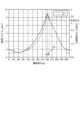
- FIG. 5is a diagram showing timings of load torque T load in electric motor 7 of compressor 904, compression chamber pressure P c of compressor 904, and loss generated in compressor 904 according to the present embodiment.
- the mechanical angles shown in FIG. 4correspond to the mechanical angles of the horizontal axis shown in FIG.
- the horizontal axisindicates the mechanical angle of one cycle of the electric motor 7
- the vertical axisindicates the load torque standard waveform, that is, the load torque T load in the electric motor 7 and the compression chamber pressure P c of the compressor 904 .
- FIG. 5the horizontal axis indicates the mechanical angle of one cycle of the electric motor 7
- the vertical axisindicates the load torque standard waveform, that is, the load torque T load in the electric motor 7 and the compression chamber pressure P c of the compressor 904 .
- the refrigerantis sucked into the suction chamber 935 of the cylinder 932 .
- the rotary piston 934rotates in the order of FIG. 4(a), FIG. 4(b), FIG. 4(c), and FIG. be.
- the refrigerantis newly sucked into the suction chamber 935 and the refrigerant filled in the portion indicated by the excluded volume is compressed in the compression chamber 945 .
- the rotary piston 934rotates in the order shown in FIGS. 4(b) and 4(c), and the discharge valve 947 opens to discharge the compressed refrigerant.
- the period of FIG. 4(c)is the period of (A) shown in FIG. 5, which is the timing at which the ejection overshoot loss occurs.
- electric motor drive device 200drives electric motor 7 and controls electric motor 7 to reduce discharge overshoot loss that occurs in compressor 904 .
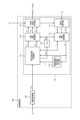
- FIG. 6is a diagram showing a configuration example of the electric motor drive device 200 according to this embodiment.
- FIG. 7is a diagram showing a configuration example of inverter 30 included in electric motor drive device 200 according to the present embodiment.
- Electric motor drive device 200is connected to AC power supply 1 and electric motor 7 .
- the electric motor drive device 200rectifies the AC voltage supplied from the AC power supply 1 , converts it to AC voltage again, supplies the AC voltage to the electric motor 7 , and drives the electric motor 7 .
- Electric motor drive device 200includes reactor 2 , rectifier circuit 3 , smoothing capacitor 5 , inverter 30 , bus voltage detector 10 , bus current detector 40 , and controller 100 .
- the rectifier circuit 3includes four diodes D1, D2, D3 and D4.
- the four diodes D1-D4are bridge-connected to form a diode bridge circuit.
- the rectifier circuit 3rectifies the AC voltage supplied from the AC power supply 1 by a diode bridge circuit composed of four diodes D1 to D4.
- one end of the input terminalis connected to the AC power supply 1 through the reactor 2 , and the other end of the input terminal is connected to the AC power supply 1 .
- an output terminalis connected to a smoothing capacitor 5 .
- a smoothing capacitor 5smoothes the output voltage of the rectifier circuit 3 .
- One electrode of the smoothing capacitor 5is connected to the first output terminal of the rectifier circuit 3 and the high potential side, ie, the positive side DC bus 12a.
- the other electrode of the smoothing capacitor 5is connected to the second output terminal of the rectifier circuit 3 and the low potential side, that is, the negative DC bus 12b.
- the voltage smoothed by the smoothing capacitor 5is called a bus voltage Vdc .
- DC buses 12 a and 12 bare lines that connect output terminals of rectifier circuit 3 , electrodes of smoothing capacitor 5 , and input terminals of inverter main circuit 310 .
- Inverter 30receives the voltage across smoothing capacitor 5, that is, bus voltage Vdc , generates a three-phase AC voltage with a variable frequency and voltage value, and supplies it to electric motor 7 via output lines 331-333.
- the inverter 30includes an inverter main circuit 310 and a drive circuit 350, as shown in FIG. Input terminals of the inverter main circuit 310 are connected to the DC buses 12a and 12b.
- the inverter main circuit 310includes switching elements 311-316. Freewheeling rectifying elements 321 to 326 are connected in anti-parallel to the switching elements 311 to 316, respectively.
- the drive circuit 350generates drive signals Sr1-Sr6 based on PWM (Pulse Width Modulation) signals Sm1-Sm6 output from the control device 100.
- PWMPulse Width Modulation
- the drive circuit 350controls on/off of the switching elements 311-316 by the drive signals Sr1-Sr6.
- the inverter 30can supply the three-phase AC voltage with variable frequency and variable voltage to the electric motor 7 via the output lines 331 to 333 .
- the PWM signals Sm1 to Sm6are signals having a logic circuit signal level, that is, a magnitude of 0V to 5V.
- the PWM signals Sm1 to Sm6are signals having the ground potential of the control device 100 as a reference potential.
- the driving signals Sr1 to Sr6are signals having voltage levels necessary to control the switching elements 311 to 316, eg, -15V to +15V.
- the drive signals Sr1 to Sr6are signals having the potential of the negative terminal, that is, the emitter terminal of the corresponding switching element as a reference potential.
- the electric motor 7is, for example, a three-phase permanent magnet synchronous motor. In this embodiment, it is assumed that the electric motor 7 drives a load element whose load torque T load periodically fluctuates, specifically the compressor 904 . In the following description, the electric motor 7 may be called a motor.
- Bus voltage detector 10detects the voltage between DC buses 12a and 12b as bus voltage Vdc .
- the bus voltage detection unit 10includes, for example, a voltage dividing circuit that divides voltage with series-connected resistors.
- the bus voltage detection unit 10converts the detected bus voltage V dc into a voltage suitable for processing in the control device 100 using a voltage dividing circuit, for example, a voltage of 5 V or less, and converts it into a voltage detection signal that is an analog signal. Output to the control device 100 .
- the voltage detection signal output from the bus voltage detection unit 10 to the control device 100is converted from an analog signal to a digital signal by an AD (Analog to Digital) conversion unit (not shown) in the control device 100, and internal processing in the control device 100 used for
- ADAnalog to Digital
- the bus current detector 40includes a shunt resistor inserted in the DC bus 12b.
- Bus current detection unit 40detects the current input to inverter 30 as DC current Idc using a shunt resistor.
- the bus current detector 40outputs the detected DC current Idc to the controller 100 as a current detection signal, which is an analog signal.
- a current detection signal output from the bus current detector 40 to the controller 100is converted from an analog signal to a digital signal by an AD converter (not shown) in the controller 100 and used for internal processing in the controller 100 .
- the control device 100generates PWM signals Sm1 to Sm6 to control the inverter 30.
- Control device 100outputs PWM signals Sm1 to Sm6 to inverter 30 to control inverter 30 .
- control device 100controls inverter 30 to change the angular frequency ⁇ and the voltage value of the output voltage of inverter 30 .
- the angular frequency ⁇ of the output voltage of the inverter 30is represented by the same symbol ⁇ as the angular frequency of the output voltage, and determines the rotational angular velocity of the electric motor 7 in electrical angle.
- the rotational angular velocitymay be simply referred to as rotational speed
- the angular frequencymay simply be referred to as frequency.
- the control device 100generates an excitation current command value i ⁇ * based on the phase currents i u , iv , and i w flowing through the electric motor 7 , and generates a ⁇ -axis voltage command value V ⁇ based on the excitation current command value i ⁇ * . * is generated. Further, the control device 100 calculates the first torque current command value i ⁇ * such that the estimated frequency value ⁇ est of the electric motor 7 matches the frequency command value ⁇ e * , and the first torque current command value i ⁇ A second torque current command value i ⁇ ** corrected for * is calculated, and a ⁇ -axis voltage command value V ⁇ * is generated based on the second torque current command value i ⁇ ** .
- Control device 100controls inverter 30 based on ⁇ -axis voltage command value V ⁇ * and ⁇ -axis voltage command value V ⁇ * .
- control device 100performs control in a rotating coordinate system having ⁇ -axes and ⁇ -axes.
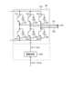
- FIG. 8is a diagram showing a configuration example of the control device 100 included in the electric motor drive device 200 according to the present embodiment.
- the control device 100includes an operation control section 102 and an inverter control section 110 .
- the operation control unit 102receives command information Q e from the outside and generates a frequency command value ⁇ e * based on the command information Q e .
- the control device 100controls the operation of each part of the air conditioner based on the command information Qe .
- the command information Qeincludes, for example, a temperature detected by a temperature sensor (not shown), information indicating a set temperature instructed by a remote controller (not shown), operation mode selection information, operation start and operation end instruction information, and the like. is.
- the operation modesare, for example, heating, cooling, and dehumidification.
- the operation control unit 102may be outside the control device 100 . That is, control device 100 may be configured to acquire frequency command value ⁇ e * from the outside.
- Inverter control unit 110includes current restoration unit 111, three-phase two-phase conversion unit 112, voltage command value calculation unit 115, two-phase three-phase conversion unit 116, PWM signal generation unit 117, and electric phase calculation unit 118. and an excitation current command value generator 119 .
- a current restoration unit 111restores the phase currents i u , iv , and i w flowing through the electric motor 7 based on the DC current I dc detected by the bus current detection unit 40 .
- Current restoration unit 111samples DC current Idc detected by bus current detection unit 40 at timing determined based on PWM signals Sm1 to Sm6 generated by PWM signal generation unit 117, thereby obtaining phase current i u , i v , i w can be recovered.
- the three-phase to two-phase conversion unit 112converts the phase currents i u , iv , and i w restored by the current restoration unit 111 to the ⁇ -axis using the electric phase ⁇ e generated by the electric phase calculation unit 118 described later.
- An excitation current i ⁇ that is a current and a torque current i ⁇ that is a ⁇ -axis current, that is,are converted into current values of the ⁇ - ⁇ axis.
- the excitation current command value generation unit 119generates the excitation current command value i ⁇ * in the above-described rotating coordinate system. Specifically, the excitation current command value generation unit 119 obtains the optimum excitation current command value i ⁇ * for driving the electric motor 7 with the highest efficiency based on the torque current i ⁇ . Based on the torque current i ⁇ , the excitation current command value generation unit 119 generates the current phase ⁇ m and An exciting current command value i ⁇ * is output.
- the excitation current command value generator 119obtains the excitation current command value i ⁇ * based on the torque current i ⁇ , but this is an example and the present invention is not limited to this. Even if the excitation current command value generator 119 obtains the excitation current command value i ⁇ * based on the excitation current i ⁇ , the frequency command value ⁇ e * , etc., the same effect can be obtained.
- the voltage command value calculation unit 115uses the frequency command value ⁇ e * obtained from the operation control unit 102, the excitation current i ⁇ and the torque current i ⁇ obtained from the three-phase two-phase conversion unit 112, and the excitation current command value generation unit Based on the excitation current command value i ⁇ * obtained from 119, the ⁇ -axis voltage command value V ⁇ * and the ⁇ -axis voltage command value V ⁇ * are generated. Furthermore, the voltage command value calculation unit 115 calculates the frequency estimated value ⁇ est based on the ⁇ -axis voltage command value V ⁇ * , the ⁇ -axis voltage command value V ⁇ * , the excitation current i ⁇ , and the torque current i ⁇ . to estimate A detailed operation of voltage command value calculation unit 115 will be described later.
- the electric phase calculator 118calculates the electric phase ⁇ e by integrating the estimated frequency value ⁇ est acquired from the voltage command value calculator 115 .
- Two-to-three phase converter 116converts ⁇ -axis voltage command value V ⁇ * and ⁇ -axis voltage command value V ⁇ * obtained from voltage command value calculator 115, that is, voltage command values in a two-phase coordinate system, to electrical phase calculation.
- the electric phase ⁇ e acquired from the unit 118the three-phase voltage command values Vu * , Vv * , Vw * , which are the output voltage command values in the three-phase coordinate system, are converted.
- PWM signal generation unit 117converts three-phase voltage command values V u * , V v * , V w * acquired from two-to-three phase conversion unit 116 and bus voltage V dc detected by bus voltage detection unit 10 to The comparison generates PWM signals Sm1-Sm6.
- the PWM signal generator 117can also stop the electric motor 7 by not outputting the PWM signals Sm1 to Sm6.
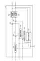
- FIG. 9is a diagram showing a configuration example of voltage command value calculation section 115 included in control device 100 according to the present embodiment.
- Voltage command value calculation unit 115includes frequency estimation unit 501, speed control unit 502, load torque estimation unit 503, compensation value calculation unit 504, addition unit 505, subtraction units 506 and 507, and excitation current control unit. 508 and a torque current control unit 509 .
- a frequency estimator 501estimates a frequency estimation value ⁇ est that indicates the rotation state of the electric motor 7 . Specifically, the frequency estimator 501 supplies the electric motor 7 with the excitation current i ⁇ , the torque current i ⁇ , the ⁇ -axis voltage command value V ⁇ * , and the ⁇ -axis voltage command value V ⁇ * . Estimate the frequency of the applied voltage and output it as the frequency estimate ⁇ est .
- the speed control unit 502generates a first torque current command value i ⁇ * based on the frequency command value ⁇ e * obtained from the operation control unit 102 and the frequency estimated value ⁇ est obtained from the frequency estimating unit 501 . do.
- the speed control unit 502uses a controller such as a proportional integral (PI) controller based on the difference between the frequency command value ⁇ e * and the frequency estimated value ⁇ est to obtain the frequency estimated value ⁇ est generates a first torque current command value i ⁇ * that matches the frequency command value ⁇ e * .
- PIproportional integral
- the load torque estimator 503estimates the load torque T load applied to the electric motor 7 based on the excitation current i ⁇ , the torque current i ⁇ , and the estimated frequency ⁇ est obtained from the frequency estimator 501 .
- a compensation value calculation unit 504calculates a torque current compensation value i ⁇ _trq * that reduces the discharge overshoot loss generated in the electric motor 7 with respect to the load torque T load estimated by the load torque estimation unit 503 .
- a detailed method of generating torque current compensation value i ⁇ _trq * in compensation value calculation section 504will be described later.
- Addition unit 505adds torque current compensation value i ⁇ _trq * to first torque current command value i ⁇ * .
- Addition unit 505outputs (i ⁇ * +i ⁇ _trq * ) obtained by adding torque current compensation value i ⁇ _trq * to first torque current command value i ⁇ * as second torque current command value i ⁇ ** .
- the subtraction unit 506calculates the difference (i ⁇ * ⁇ i ⁇ ) of the excitation current i ⁇ with respect to the excitation current command value i ⁇ * .
- the subtraction unit 507calculates the difference (i ⁇ ** - i ⁇ ) of the torque current i ⁇ with respect to the second torque current command value i ⁇ **.
- An excitation current control unit 508performs a proportional integral operation on the difference (i ⁇ * ⁇ i ⁇ ) calculated by the subtraction unit 506 to bring the difference (i ⁇ * ⁇ i ⁇ ) close to zero. Generate the value V ⁇ * .
- the excitation current control unit 508generates the ⁇ -axis voltage command value V ⁇ * in this manner, thereby performing control for matching the excitation current i ⁇ with the excitation current command value i ⁇ * .
- a torque current control unit 509performs a proportional integral operation on the difference (i ⁇ ** - i ⁇ ) calculated by the subtraction unit 507 to bring the difference (i ⁇ ** - i ⁇ ) close to zero.
- a voltage command value V ⁇ *is generated.
- the torque current control unit 509performs control to match the torque current i ⁇ with the second torque current command value i ⁇ ** .
- the proportional gain Kp_ ⁇ of the excitation current control unit 508is expressed by ⁇ cc ⁇ L ⁇
- the integral gain Ki_ ⁇is expressed using the phase resistance R of the electric motor 7 ( R/L ⁇ ) ⁇ Kp_ ⁇ .
- the proportional gain Kp_ ⁇ of the torque current control unit 509is expressed by ⁇ cc ⁇ L ⁇
- the integral gain Ki_ ⁇is expressed by (R/L ⁇ ) ⁇ Kp_ ⁇ using the phase resistance R of the electric motor 7 .
- the voltage command value calculation unit 115can shorten the time for the exciting current i ⁇ to follow the exciting current command value i ⁇ * .
- the time for the torque current i ⁇ to follow the value i ⁇ *can be shortened.
- the current control response ⁇ cccannot be infinitely increased, and must be set to a value that is relatively small with respect to the control cycle.
- motor drive device 200is configured to restore phase currents i u , iv , and i w from DC current I dc on the input side of inverter 30 , but is not limited to this.
- Electric motor drive device 200may include current detectors in output lines 331, 332, and 333 of inverter 30 to detect phase currents iu , iv , and iw . In this case, the electric motor drive device 200 may use the current value detected by the current detector instead of the current restored by the current restoration section 111 .
- the switching elements 311 to 316 of the inverter main circuit 310are assumed to be IGBTs (Insulated Gate Bipolar Transistors), MOSFETs (Metal Oxide Semiconductor Field Effect Transistors), etc., but switching can be performed. Any element may be used as long as it is a suitable element.
- the switching elements 311 to 316are MOSFETs
- the MOSFETshave parasitic diodes due to their structure, so the same effect can be obtained without connecting the rectifying elements 321 to 326 for freewheeling in anti-parallel. can be done.
- the materials constituting the switching elements 311 to 316not only silicon (Si) but also wide bandgap semiconductors such as silicon carbide (SiC), gallium nitride (GaN), and diamond are used. Loss can be reduced.
- the electric motor driving device 200controls to accelerate the electric motor 7 at the timing when the discharge overshoot loss occurs.
- the electric motor drive device 200can operate the compressor 904 with high efficiency while reducing the discharge overshoot loss of the compressor 904 .
- a specific control method in electric motor drive device 200will be described. is not limited to
- the load torque estimator 503uses a disturbance observer to estimate the load torque T load .
- the load torque T loadcan be derived as the following equation (1) from the equation of motion using the output torque T m , the rotational angular velocity ⁇ m , and the inertia J m of the load.
- the equation (1)can be expressed as an arithmetic expression of the disturbance observer like the equation (2).
- the estimated value of the load torque T loadis T load ⁇
- the Laplace operatoris s.
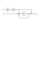
- FIG. 10is a diagram showing an example of a disturbance observer configured by load torque estimation section 503 of electric motor drive device 200 according to the present embodiment.
- the load torque estimator 503can obtain the load torque estimated value T load ⁇ , which is the estimated value of the load torque T load .
- the output torque Tmis represented by the formula (4).
- Pmis the number of pole pairs of the motor 7
- ⁇ fis the magnetic flux of the motor 7
- Ldis the d-axis inductance
- Lqis the q-axis inductance.
- the load torque estimator 503can calculate the output torque Tm , for example, by storing these parameters in advance.
- Load torque estimator 503outputs load torque estimated value T load ⁇ to compensation value calculator 504 as estimated load torque T load .
- FIG. 11shows load torque T load estimated by load torque estimating section 503 of electric motor drive device 200 according to the present embodiment, compression chamber pressure P c of compressor 904, and torque current generated by compensation value computing section 504.
- FIG. 4is a diagram showing an example of compensation value i ⁇ _trq * ;
- compensation value calculator 504calculates torque current compensation value i ⁇ _trq Generate and output.
- the adding section 505adds the torque current compensation value i ⁇ _trq * to the first torque current command value i ⁇ * to generate the second torque current command value i ⁇ ** .
- the control device 100adds the torque current compensation value i ⁇ _trq * during the period (A) including the timing at which the load torque T load peaks and the discharge valve 947 opens, thereby causing rapid acceleration.
- the electric motor 7, that is, the compressor 904is driven as follows.
- the limit value of the torque current compensation value i ⁇ _trq * generated by the compensation value calculation unit 504is represented by Equation (5). That is, the limit value i ⁇ _trq * _lim of the torque current compensation value i ⁇ _trq * is a value obtained by subtracting the first torque current command value i ⁇ * from the overall limit value i ⁇ _lim * of the torque current i ⁇ .
- the torque current compensation value i ⁇ _trq *may be just above the limit as shown in FIG. 11(a), or may have some margin as shown in FIG. 11(b). Also, there is no particular limitation on the slope of increasing the torque current compensation value i ⁇ _trq * . As a result, the control device 100 can shorten the time during which the discharge overshoot loss occurs, and can reduce the discharge overshoot loss.
- the speedis equal to the speed command value on average outside the period of (A) in FIG. There is no problem even if the first torque current command value i ⁇ * is adjusted so as to follow.
- the control device 100should set the timing of switching the torque current compensation value i ⁇ _trq * in the period (A) shown in FIG. is not limited to the timing shown in .
- the electric motor drive device 200is used in the refrigeration cycle application equipment 900 including the compressor 904, and depending on the type of refrigerant compressed by the compressor 904, the value of the torque current compensation value i ⁇ _trq * , the torque current compensation value i Since the mechanical loss changes depending on the period during which the value of ⁇ _trq * is increased or decreased, the optimum torque current compensation value i ⁇ _trq * differs under each condition.
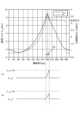
- FIG. 12is a diagram showing an operation example of control device 100 included in electric motor drive device 200 according to the present embodiment.
- FIG. 12(a)shows the rotation speed of the electric motor 7 when the rotation speed of the electric motor 7 is changed as in the present embodiment and when the rotation speed of the electric motor 7 is not changed as a comparative example. Further, FIG. 12(a) shows a component obtained by differentiating the rotation speed when the rotation speed of the electric motor 7 is changed as in the present embodiment.
- FIG. 12(b)shows the discharge overshoot loss when the rotation speed of the electric motor 7 is changed as in this embodiment and when the rotation speed of the electric motor 7 is not changed as a comparative example.
- the horizontal axesboth indicate time.
- the control device 100adds the torque current compensation values i ⁇ _trq * in the period of (A) of FIGS. An effect of suppressing loss can be obtained.
- the refrigerant used in the refrigeration cycle applied device 900 according to the present embodimentis not particularly limited, and may be a so-called old refrigerant or a new refrigerant.
- Old refrigerantsare, for example, refrigerants such as R410 and R32.
- the new refrigerantsare, for example, refrigerants such as trifluoroethylene (HFO1123), trifluoromethane (CF31), propane (R290).
- FIG. 13is a flowchart showing the operation of control device 100 included in electric motor drive device 200 according to the present embodiment.
- the flowchart shown in FIG. 13specifically shows the operation of the voltage command value calculation unit 115 .
- the frequency estimator 501estimates a frequency estimation value ⁇ est which is the current speed of the electric motor 7 and indicates the rotation state (step S1).
- the speed control unit 502generates the first torque current command value i ⁇ * based on the deviation between the frequency estimated value ⁇ est of the electric motor 7 and the frequency command value ⁇ e * (step S2).
- the load torque estimator 503estimates the load torque T load applied to the electric motor 7 (step S3).
- the compensation value calculation unit 504calculates a torque current compensation value i ⁇ _trq * that accelerates the electric motor 7 one or more times during one cycle of the mechanical angle of the electric motor 7 (step S4).
- the adder 505generates a second torque current command value i ⁇ ** based on the first torque current command value i ⁇ * and the torque current compensation value i ⁇ _trq * (step S5).
- the subtractor 506calculates the difference (i ⁇ * ⁇ i ⁇ ) between the excitation current command value i ⁇ * and the excitation current i ⁇ (step S6).
- the subtraction unit 507calculates the difference (i ⁇ ** - i ⁇ ) between the second torque current command value i ⁇ ** and the torque current i ⁇ (step S7).
- the excitation current control unit 508generates the ⁇ -axis voltage command value V ⁇ * based on the difference (i ⁇ * ⁇ i ⁇ ) calculated by the subtraction unit 506 (step S8).
- Torque current control unit 509generates ⁇ -axis voltage command value V ⁇ * based on the difference (i ⁇ ** - i ⁇ ) calculated by subtraction unit 507 (step S9).
- the compensation value calculation unit 504calculates a torque current compensation value i ⁇ _trq * for accelerating the electric motor 7 in a period including the timing when the load torque T load reaches a maximum so as to reduce the discharge overshoot loss of the compressor 904. Calculate.
- the period including the timing at which the load torque T load becomes maximumis the period (A) shown in FIG.
- the compensation value calculation unit 504calculates the torque current compensation value i ⁇ _trq * so as to accelerate the electric motor 7 when the load torque T load exceeds the threshold. At this time, the compensation value calculation unit 504 calculates the threshold value based on the load torque T load estimated in the previous control. Compensation value calculation section 504 may use the latest load torque T load as the load torque T load estimated in the previous control , or use the average value of the load torque T load for a plurality of times including the latest. good too.
- the compensation value calculation unit 504may accelerate the electric motor 7 based on the mechanical angle corresponding to the estimated load torque T load to calculate the torque current compensation value i ⁇ _trq * . Further, the compensation value calculation unit 504 calculates the torque current compensation value i ⁇ _trq * so as to accelerate the electric motor 7 based on the above threshold and the mechanical angle corresponding to the estimated load torque T load . good too. Further, the compensation value calculation unit 504 may keep the magnitude of the acceleration constant during the period in which the electric motor 7 is accelerated, or may change the magnitude of the acceleration according to the estimated load torque T load or the like. good.
- FIG. 14is a diagram showing an example of a hardware configuration for realizing control device 100 provided in electric motor drive device 200 according to the present embodiment.
- Control device 100is implemented by processor 91 and memory 92 .
- the processor 91is a CPU (Central Processing Unit, central processing unit, processing unit, arithmetic unit, microprocessor, microcomputer, processor, DSP (Digital Signal Processor)), or a system LSI (Large Scale Integration).
- the memory 92includes RAM (Random Access Memory), ROM (Read Only Memory), flash memory, EPROM (Erasable Programmable Read Only Memory), EEPROM (registered trademark) (Electrically Erasable Programmable Read Non-volatile or volatile such as Only Memory)
- RAMRandom Access Memory
- ROMRead Only Memory
- flash memoryflash memory
- EPROMErasable Programmable Read Only Memory
- EEPROMregistered trademark
- a semiconductor memorycan be exemplified.
- the memory 92is not limited to these, and may be a magnetic disk, an optical disk, a compact disk, a mini disk, or a DVD (Digital Versatile Disc).
- the control device 100estimates the load torque T load of the electric motor 7, and the load torque T load is A torque current command value is controlled so as to accelerate in a period including the largest mechanical angle, and discharge overshoot loss is reduced.
- the electric motor drive device 200can reduce loss generated in the compressor 904 including the electric motor 7 and reduce power consumption in the refrigeration cycle application equipment 900 including the compressor 904 .
- the electric motor drive device 200reduces the mechanical loss due to the overshoot loss that occurs at the timing when the discharge valve 947 opens, thereby increasing the efficiency of the refrigerating cycle device 900. driving can be realized.
- Electric motor drive device 200can apply the above-described control according to the present embodiment even when compressor 904 used in refrigeration cycle applied equipment 900 is a twin rotary compressor, a scroll compressor, or the like.
- the compensation value calculation unit 504calculates the torque current compensation value i ⁇ _trq * that accompanies the acceleration operation of the electric motor 7 according to the number of load fluctuations that occur during one rotation of the electric motor 7 .
- the motor drive device 200can be applied to any control system that has a speed controller and a current controller in control means for driving the motor 7 .
- the electric motor drive device 200 of the present embodimentis suitable for the refrigeration cycle application equipment 900 that switches the windings of the electric motor 7 for use.
- an air conditioneris given as an example of the refrigeration cycle application equipment 900, the present embodiment is not limited to this, and can be applied to refrigerators, freezers, heat pump water heaters, and the like, for example.
Landscapes
- Engineering & Computer Science (AREA)
- Power Engineering (AREA)
- Physics & Mathematics (AREA)
- Mechanical Engineering (AREA)
- Thermal Sciences (AREA)
- General Engineering & Computer Science (AREA)
- Control Of Ac Motors In General (AREA)
Abstract
Description
Translated fromJapanese本開示は、電動機を駆動する電動機駆動装置および冷凍サイクル適用機器に関する。The present disclosure relates to an electric motor drive device that drives an electric motor and a refrigeration cycle application device.
負荷トルクが機械角の1周期または複数周期で変化する圧縮機などの負荷の場合、電動機駆動装置から電動機に供給される電流も負荷トルクの脈動に応じて変動する。そのため、電動機駆動装置は、電動機に供給する電流の振幅値の変動が小さくなるように電流の振幅値を制御することによって、高効率な運転が可能となる。特許文献1には、モータ制御装置が、積分制御によりq軸電流指令の脈動成分、すなわち交流成分がゼロになるように制御し、効率良くモータを駆動する技術が開示されている。In the case of a load such as a compressor whose load torque changes in one or more cycles of the mechanical angle, the current supplied from the motor drive device to the motor also fluctuates according to the pulsation of the load torque. Therefore, the electric motor driving device can operate with high efficiency by controlling the amplitude value of the current so that the fluctuation of the amplitude value of the electric current supplied to the electric motor is reduced.
しかしながら、上記従来の技術によれば、モータに流れる電流による銅損の損失は小さくなる可能性はあるが、圧縮機などの負荷を含めた装置全体での効率は考慮されていない。そのため、圧縮機などの負荷を含めた装置全体では、高効率な運転にならない可能性がある、という問題があった。However, according to the conventional technology described above, although there is a possibility that the copper loss caused by the current flowing in the motor can be reduced, the efficiency of the entire device, including the load such as the compressor, is not taken into consideration. Therefore, there is a problem that the entire device including the load such as the compressor may not operate with high efficiency.
本開示は、上記に鑑みてなされたものであって、電動機を含む圧縮機で発生する損失を低減し、圧縮機を備える冷凍サイクル適用機器において消費電力を低減可能な電動機駆動装置を得ることを目的とする。The present disclosure has been made in view of the above, and aims to obtain an electric motor drive device capable of reducing loss generated in a compressor including an electric motor and reducing power consumption in a refrigeration cycle application device including the compressor. aim.
上述した課題を解決し、目的を達成するために、本開示に係る電動機駆動装置は、圧縮機の負荷による周期的な負荷変動によって速度変化が生じる電動機に、周波数および電圧値が可変の交流電圧を供給するインバータと、インバータを制御する制御装置と、を備える。制御装置は、電動機の回転状態を示す周波数推定値を推定する周波数推定部と、周波数推定値と周波数指令値との偏差に基づいて、第1のトルク電流指令値を生成する速度制御部と、電動機にかかる負荷トルクを推定する負荷トルク推定部と、負荷トルクに基づいて、負荷トルクが最大となるタイミングを含む期間において電動機を加速運転させるトルク電流補償値を演算する補償値演算部と、第1のトルク電流指令値とトルク電流補償値とに基づいて、第2のトルク電流指令値を生成する加算部と、を備える。In order to solve the above-described problems and achieve the object, the electric motor drive device according to the present disclosure supplies an alternating current voltage with a variable frequency and voltage value to the electric motor whose speed changes due to periodic load fluctuations caused by the load of the compressor. and a controller for controlling the inverter. The control device includes a frequency estimating unit that estimates a frequency estimated value indicating the rotation state of the electric motor, a speed control unit that generates a first torque current command value based on a deviation between the frequency estimated value and the frequency command value, a load torque estimator for estimating the load torque applied to the electric motor; a compensation value calculator for calculating, based on the load torque, a torque current compensation value for accelerating operation of the electric motor in a period including a timing when the load torque is maximized; an adder that generates a second torque current command value based on the one torque current command value and the torque current compensation value.
本開示に係る電動機駆動装置は、電動機を含む圧縮機で発生する損失を低減し、圧縮機を備える冷凍サイクル適用機器において消費電力を低減できる、という効果を奏する。The electric motor drive device according to the present disclosure has the effect of reducing loss generated in a compressor including an electric motor and reducing power consumption in a refrigeration cycle application device including the compressor.
以下に、本開示の実施の形態に係る電動機駆動装置および冷凍サイクル適用機器を図面に基づいて詳細に説明する。A motor drive device and a refrigeration cycle application device according to an embodiment of the present disclosure will be described below in detail based on the drawings.
実施の形態.
図1は、本実施の形態に係る冷凍サイクル適用機器900の構成例を示す図である。冷凍サイクル適用機器900は、電動機駆動装置200を備える。冷凍サイクル適用機器900は、空気調和機、冷蔵庫、冷凍庫、ヒートポンプ給湯器といった冷凍サイクルを備える製品に適用することが可能である。電動機駆動装置200は、圧縮機904に内蔵される電動機7を駆動することによって、冷凍サイクル適用機器900を動作させる。Embodiment.
FIG. 1 is a diagram showing a configuration example of a refrigeration cycle equipment 900 according to the present embodiment. A refrigeration cycle application device 900 includes an electric
冷凍サイクル適用機器900は、電動機7を内蔵した圧縮機904と、四方弁902と、室内熱交換器906と、膨張弁908と、室外熱交換器910とが冷媒配管912を介して取り付けられている。圧縮機904の内部には、冷媒を圧縮する圧縮機構924と、圧縮機構924を動作させる電動機7とが設けられている。冷凍サイクル適用機器900は、四方弁902の切替動作により暖房運転又は冷房運転をすることができる。圧縮機構924は、可変速制御される電動機7によって駆動される。A refrigeration cycle application device 900 includes a
暖房運転時には、実線矢印で示すように、冷媒が圧縮機構924で加圧されて送り出され、四方弁902、室内熱交換器906、膨張弁908、室外熱交換器910及び四方弁902を通って圧縮機構924に戻る。冷房運転時には、破線矢印で示すように、冷媒が圧縮機構924で加圧されて送り出され、四方弁902、室外熱交換器910、膨張弁908、室内熱交換器906及び四方弁902を通って圧縮機構924に戻る。During heating operation, as indicated by solid line arrows, the refrigerant is pressurized by the
暖房運転時には、室内熱交換器906が凝縮器として作用して熱放出を行い、室外熱交換器910が蒸発器として作用して熱吸収を行う。冷房運転時には、室外熱交換器910が凝縮器として作用して熱放出を行い、室内熱交換器906が蒸発器として作用し、熱吸収を行う。膨張弁908は、冷媒を減圧して膨張させる。圧縮機904は、可変速制御される電動機7によって駆動される。During heating operation, the
電動機駆動装置200が駆動する対象の電動機7を内蔵する圧縮機904の構成について説明する。図2は、本実施の形態に係る冷凍サイクル適用機器900が備える圧縮機904の構成の概略を示す断面図である。図3は、本実施の形態に係る冷凍サイクル適用機器900が備える圧縮機904の図2に示す2B-2B線による断面図において圧縮機904で発生する損失を模式的に示す図である。圧縮機904は、密閉式のロータリ圧縮機であり、密閉容器を構成する圧縮機シェル922と、圧縮機シェル922内に配置された圧縮機構924と、を備える。圧縮機904において、冷媒は、吸入配管926から圧縮機構924内に導かれ、吐出配管928から吐出される。圧縮機シェル922は、支持部材930に支持されている。圧縮機構924は、シリンダ932と、シリンダ932内に配置されたロータリピストン934と、を備える。The configuration of the
電動機7は、圧縮機シェル922内に配置されており、回転子7aと、回転子7aを回転可能に保持する固定子7bと、を備える。回転子7aは、シャフト936に結合されている。シャフト936は、図示しない軸受けにより、図示しないフレームに対して回転可能に保持されている。該フレームは、圧縮機シェル922に固定されている。シャフト936は、ロータリピストン934に結合されている。電動機7の回転子7aの回転は、シャフト936を介して、ロータリピストン934に伝達される。本実施の形態において、電動機7は、圧縮機904の負荷による周期的な負荷変動によって速度変化が生じることになる。The
シリンダ932には、吸込み口942と、吐出口944と、が形成されている。シリンダ932内には、ベーン946が設けられている。吸込み口942は、吸入配管926に接続されている。吐出口944は、吐出配管928に接続されている。なお、図3において、吸込み口942および吐出口944は概念的に図示されており、各々の位置は必ずしも実際の位置を正確に表すものではない。ベーン946は、シリンダ932の中心に向かって付勢されており、ロータリピストン934の周面上を摺動しつつ、シリンダ932の径方向に移動することができるようになっている。A
シャフト936が回転すると、ロータリピストン934が矢印RPで示す方向に回転する。その結果、シリンダ932では、吸込み口942から気化した冷媒が吸い込まれ、冷媒が圧縮され、圧縮により液化された冷媒が吐出口944から吐出される。図3に示すように、シリンダ932では、吐出弁947が開くタイミングでメカロスとなる吐出オーバーシュート損失が発生する。シリンダ932では、吸込み、圧縮、および吐出の一連の工程においてロータリピストン934に掛かる圧力が変化する。この圧力の変化が、圧縮機904の電動機7にかかる負荷トルクTloadの変化となる。As
図4は、本実施の形態に係る圧縮機904のシリンダ932における冷媒の吸込み、圧縮、および吐出の工程を模式的に示す図である。図5は、本実施の形態に係る圧縮機904の電動機7における負荷トルクTload、圧縮機904の圧縮室圧力Pc、および圧縮機904で発生する損失のタイミングを示す図である。図4に示す機械角は、図5に示す横軸の機械角に対応している。図5において、横軸は電動機7の1周期の機械角を示し、縦軸は負荷トルク標準波形、すなわち電動機7における負荷トルクTload、および圧縮機904の圧縮室圧力Pcを示している。図4(a)において、シリンダ932の吸入室935に冷媒が吸入される。シリンダ932では、図4(a)から、図4(b)、図4(c)、図4(d)の順にロータリピストン934が回転することによって、排除容積で示される部分に冷媒が充填される。次の図4(a)のタイミングにおいて、新たに吸入室935に冷媒が吸入されるとともに、排除容積で示される部分に充填された冷媒が圧縮室945において圧縮される。シリンダ932では、図4(b)、図4(c)の順にロータリピストン934が回転し、吐出弁947が開くことによって、圧縮された冷媒が吐出される。図4(c)の期間が図5に示す(A)の期間であり、吐出オーバーシュート損失が発生するタイミングである。FIG. 4 is a diagram schematically showing the process of drawing, compressing, and discharging refrigerant in
上記のように、電動機7が圧縮機シェル922内に配置されているので、電動機7は圧縮機904の一部であり、電動機7は、圧縮機904の圧縮機構924を駆動するものであると見ることもできる。以下に詳しく述べるように、本実施の形態において、電動機駆動装置200は、電動機7を駆動するものであり、電動機7を制御することによって、圧縮機904で発生する吐出オーバーシュート損失を低減する。Since the
電動機駆動装置200の構成について説明する。図6は、本実施の形態に係る電動機駆動装置200の構成例を示す図である。図7は、本実施の形態に係る電動機駆動装置200が備えるインバータ30の構成例を示す図である。電動機駆動装置200は、交流電源1および電動機7に接続される。電動機駆動装置200は、交流電源1から供給される交流電圧を整流し、再度交流電圧に変換して電動機7に供給して、電動機7を駆動する。電動機駆動装置200は、リアクタ2と、整流回路3と、平滑コンデンサ5と、インバータ30と、母線電圧検出部10と、母線電流検出部40と、制御装置100と、を備える。The configuration of the electric
整流回路3は、4つのダイオードD1,D2,D3,D4を備える。4つのダイオードD1~D4は、ブリッジ接続され、ダイオードブリッジ回路を構成する。整流回路3は、4つのダイオードD1~D4から構成されるダイオードブリッジ回路によって、交流電源1から供給される交流電圧を整流する。整流回路3において、入力端子の一端はリアクタ2を介して交流電源1に接続され、入力端子の他端は交流電源1に接続されている。また、整流回路3において、出力端子は平滑コンデンサ5に接続されている。The
平滑コンデンサ5は、整流回路3の出力電圧を平滑する。平滑コンデンサ5の一方の電極は、整流回路3の第1の出力端子、および高電位側、すなわち正側の直流母線12aに接続されている。平滑コンデンサ5の他方の電極は、整流回路3の第2の出力端子、および低電位側、すなわち負側の直流母線12bに接続されている。平滑コンデンサ5で平滑された電圧を母線電圧Vdcと称する。直流母線12a,12bは、整流回路3の出力端子、平滑コンデンサ5の電極、およびインバータ主回路310の入力端子を結ぶ線である。A smoothing
インバータ30は、平滑コンデンサ5の両端電圧、すなわち母線電圧Vdcを受けて、周波数および電圧値が可変の3相交流電圧を発生して、出力線331~333を介して電動機7に供給する。インバータ30は、図7に示すように、インバータ主回路310と、駆動回路350と、を備える。インバータ主回路310の入力端子は、直流母線12a,12bに接続されている。インバータ主回路310は、スイッチング素子311~316を備える。スイッチング素子311~316の各々には、還流用の整流素子321~326が逆並列接続されている。
駆動回路350は、制御装置100から出力されるPWM(Pulse Width Modulation)信号Sm1~Sm6に基づいて、駆動信号Sr1~Sr6を生成する。駆動回路350は、駆動信号Sr1~Sr6によってスイッチング素子311~316のオンオフを制御する。これにより、インバータ30は、周波数可変かつ電圧可変の3相交流電圧を、出力線331~333を介して電動機7に供給することができる。The
PWM信号Sm1~Sm6は、論理回路の信号レベル、すなわち0V~5Vの大きさを持つ信号である。PWM信号Sm1~Sm6は、制御装置100の接地電位を基準電位とする信号である。一方、駆動信号Sr1~Sr6は、スイッチング素子311~316を制御するのに必要な電圧レベル、例えば、-15V~+15Vの大きさを持つ信号である。駆動信号Sr1~Sr6は、それぞれ対応するスイッチング素子の負側の端子、すなわちエミッタ端子の電位を基準電位とする信号である。The PWM signals Sm1 to Sm6 are signals having a logic circuit signal level, that is, a magnitude of 0V to 5V. The PWM signals Sm1 to Sm6 are signals having the ground potential of the
電動機7は、例えば、3相永久磁石同期電動機である。本実施の形態では、電動機7は、負荷トルクTloadが周期的に変動する負荷要素、具体的には圧縮機904を駆動することを想定している。以降の説明において、電動機7のことをモータと称することがある。The
母線電圧検出部10は、直流母線12a,12b間の電圧を母線電圧Vdcとして検出する。母線電圧検出部10は、例えば、直列接続された抵抗で分圧する分圧回路を備える。母線電圧検出部10は、検出した母線電圧Vdcを、分圧回路を用いて制御装置100での処理に適した電圧、例えば、5V以下の電圧に変換し、アナログ信号である電圧検出信号として制御装置100に出力する。母線電圧検出部10から制御装置100に出力される電圧検出信号は、制御装置100内の図示しないAD(Analog to Digital)変換部によってアナログ信号からデジタル信号に変換され、制御装置100での内部処理に用いられる。
母線電流検出部40は、直流母線12bに挿入されたシャント抵抗を備える。母線電流検出部40は、シャント抵抗を用いて、インバータ30に入力される電流を直流電流Idcとして検出する。母線電流検出部40は、検出した直流電流Idcを、アナログ信号である電流検出信号として制御装置100に出力する。母線電流検出部40から制御装置100に出力される電流検出信号は、制御装置100内の図示しないAD変換部によってアナログ信号からデジタル信号に変換され、制御装置100での内部処理に用いられる。The
制御装置100は、インバータ30を制御するため、PWM信号Sm1~Sm6を生成する。制御装置100は、PWM信号Sm1~Sm6をインバータ30に出力して、インバータ30を制御する。具体的には、制御装置100は、インバータ30を制御して、インバータ30の出力電圧の角周波数ωおよび電圧値を変化させる。The
インバータ30の出力電圧の角周波数ωは、出力電圧の角周波数と同じ符号ωで表されるものであって、電動機7の電気角での回転角速度を定めるものである。電動機7の機械角での回転角速度ωmは、電動機7の電気角での回転角速度ωを極対数Pmで割ったものに等しい。従って、電動機7の機械角での回転角速度ωmと、インバータ30の出力電圧の角周波数ωとの間には、ωm=ω/Pmの関係がある。以降の説明において、回転角速度を単に回転速度と称し、角周波数を単に周波数と称することがある。The angular frequency ω of the output voltage of the
制御装置100は、電動機7に流れる相電流iu,iv,iwに基づいて励磁電流指令値iγ*を生成し、励磁電流指令値iγ*に基づいてγ軸電圧指令値Vγ*を生成する。また、制御装置100は、電動機7の周波数推定値ωestを周波数指令値ωe*に一致させるように第1のトルク電流指令値iδ*を算出し、第1のトルク電流指令値iδ*を補正した第2のトルク電流指令値iδ**を算出し、第2のトルク電流指令値iδ**に基づいてδ軸電圧指令値Vδ*を生成する。制御装置100は、γ軸電圧指令値Vγ*およびδ軸電圧指令値Vδ*に基づいてインバータ30を制御する。このように、本実施の形態において、制御装置100は、γ軸およびδ軸を有する回転座標系において制御を行う。The
制御装置100の構成について説明する。図8は、本実施の形態に係る電動機駆動装置200が備える制御装置100の構成例を示す図である。制御装置100は、運転制御部102と、インバータ制御部110と、を備える。The configuration of the
運転制御部102は、外部から指令情報Qeを受け、指令情報Qeに基づいて、周波数指令値ωe*を生成する。周波数指令値ωe*は、電動機7の回転速度の指令値である回転角速度指令値ωm*に極対数Pmを乗算する、すなわちωe*=ωm*×Pmによって求めることができる。The
制御装置100は、冷凍サイクル適用機器900として空気調和機を制御する場合、指令情報Qeに基づいて空気調和機の各部の動作を制御する。指令情報Qeは、例えば、図示しない温度センサで検出された温度、図示しない操作部であるリモコンから指示される設定温度を示す情報、運転モードの選択情報、運転開始及び運転終了の指示情報などである。運転モードとは、例えば、暖房、冷房、除湿などである。なお、運転制御部102については、制御装置100の外部にあってもよい。すなわち、制御装置100は、外部から周波数指令値ωe*を取得する構成であってもよい。When controlling an air conditioner as the refrigeration cycle applied equipment 900, the
インバータ制御部110は、電流復元部111と、3相2相変換部112と、電圧指令値演算部115と、2相3相変換部116と、PWM信号生成部117と、電気位相演算部118と、励磁電流指令値生成部119と、を備える。
電流復元部111は、母線電流検出部40で検出された直流電流Idcに基づいて電動機7に流れる相電流iu,iv,iwを復元する。電流復元部111は、母線電流検出部40で検出された直流電流Idcを、PWM信号生成部117で生成されたPWM信号Sm1~Sm6に基づいて定められるタイミングでサンプリングすることによって、相電流iu,iv,iwを復元することができる。A
3相2相変換部112は、電流復元部111で復元された相電流iu,iv,iwを、後述する電気位相演算部118で生成された電気位相θeを用いて、γ軸電流である励磁電流iγ、およびδ軸電流であるトルク電流iδ、すなわちγ-δ軸の電流値に変換する。The three-phase to two-
励磁電流指令値生成部119は、前述の回転座標系における励磁電流指令値iγ*を生成する。具体的には、励磁電流指令値生成部119は、トルク電流iδに基づいて、電動機7を駆動するために最も効率が良くなる最適な励磁電流指令値iγ*を求める。励磁電流指令値生成部119は、トルク電流iδに基づいて、出力トルクTmが規定された値以上または最大になる、すなわち電流値が規定された値以下または最小になる電流位相βmとなる励磁電流指令値iγ*を出力する。なお、ここでは、励磁電流指令値生成部119が、トルク電流iδに基づいて励磁電流指令値iγ*を求めているが、一例であり、これに限定されない。励磁電流指令値生成部119は、励磁電流iγ、周波数指令値ωe*などに基づいて励磁電流指令値iγ*を求めても、同様の効果を得ることができる。The excitation current command
電圧指令値演算部115は、運転制御部102から取得した周波数指令値ωe*と、3相2相変換部112から取得した励磁電流iγおよびトルク電流iδと、励磁電流指令値生成部119から取得した励磁電流指令値iγ*とに基づいて、γ軸電圧指令値Vγ*およびδ軸電圧指令値Vδ*を生成する。さらに、電圧指令値演算部115は、γ軸電圧指令値Vγ*と、δ軸電圧指令値Vδ*と、励磁電流iγと、トルク電流iδとに基づいて、周波数推定値ωestを推定する。電圧指令値演算部115の詳細な動作については後述する。The voltage command
電気位相演算部118は、電圧指令値演算部115から取得した周波数推定値ωestを積分することで、電気位相θeを演算する。The
2相3相変換部116は、電圧指令値演算部115から取得したγ軸電圧指令値Vγ*およびδ軸電圧指令値Vδ*、すなわち2相座標系の電圧指令値を、電気位相演算部118から取得した電気位相θeを用いて、3相座標系の出力電圧指令値である3相電圧指令値Vu*,Vv*,Vw*に変換する。Two-to-three
PWM信号生成部117は、2相3相変換部116から取得した3相電圧指令値Vu*,Vv*,Vw*と、母線電圧検出部10で検出された母線電圧Vdcとを比較することによって、PWM信号Sm1~Sm6を生成する。なお、PWM信号生成部117は、PWM信号Sm1~Sm6を出力しないようにすることによって、電動機7を停止することも可能である。PWM
電圧指令値演算部115の構成および動作について詳細に説明する。図9は、本実施の形態に係る制御装置100が備える電圧指令値演算部115の構成例を示す図である。電圧指令値演算部115は、周波数推定部501と、速度制御部502と、負荷トルク推定部503と、補償値演算部504と、加算部505と、減算部506,507と、励磁電流制御部508と、トルク電流制御部509と、を備える。The configuration and operation of the voltage command
周波数推定部501は、電動機7の回転状態を示す周波数推定値ωestを推定する。具体的には、周波数推定部501は、励磁電流iγと、トルク電流iδと、γ軸電圧指令値Vγ*と、δ軸電圧指令値Vδ*とに基づいて、電動機7に供給される電圧の周波数を推定し、周波数推定値ωestとして出力する。A frequency estimator 501 estimates a frequency estimation value ωest that indicates the rotation state of the
速度制御部502は、運転制御部102から取得した周波数指令値ωe*と、周波数推定部501から取得した周波数推定値ωestとに基づいて、第1のトルク電流指令値iδ*を生成する。速度制御部502は、例えば、周波数指令値ωe*と周波数推定値ωestとの差分に基づいて、比例積分(PI:Proportional Integral)制御器などの制御器を用いて、周波数推定値ωestが周波数指令値ωe*に一致するような第1のトルク電流指令値iδ*を生成する。The speed control unit 502 generates a first torque current command value iδ* based on the frequency command value ω e* obtained from the
負荷トルク推定部503は、励磁電流iγと、トルク電流iδと、周波数推定部501から取得した周波数推定値ωestとに基づいて、電動機7にかかる負荷トルクTloadを推定する。The load torque estimator 503 estimates the load torque Tload applied to the
補償値演算部504は、負荷トルク推定部503で推定された負荷トルクTloadに対して電動機7で発生する吐出オーバーシュート損失を低減するようなトルク電流補償値iδ_trq*を演算する。補償値演算部504における詳細なトルク電流補償値iδ_trq*の生成方法については後述する。A compensation value calculation unit 504 calculates a torque current compensation value iδ_trq* that reduces the discharge overshoot loss generated in the
加算部505は、第1のトルク電流指令値iδ*にトルク電流補償値iδ_trq*を加算する。加算部505は、第1のトルク電流指令値iδ*にトルク電流補償値iδ_trq*を加算した(iδ*+iδ_trq*)を第2のトルク電流指令値iδ**として出力する。
減算部506は、励磁電流指令値iγ*に対する励磁電流iγの差分(iγ*-iγ)を算出する。減算部507は、第2のトルク電流指令値iδ**に対するトルク電流iδの差分(iδ**-iδ)を算出する。The
励磁電流制御部508は、減算部506で算出された差分(iγ*-iγ)に対して比例積分演算を行って、差分(iγ*-iγ)をゼロに近付けるγ軸電圧指令値Vγ*を生成する。励磁電流制御部508は、このようにしてγ軸電圧指令値Vγ*を生成することで、励磁電流iγを励磁電流指令値iγ*に一致させるための制御を行う。An excitation
トルク電流制御部509は、減算部507で算出された差分(iδ**-iδ)に対して比例積分演算を行って、差分(iδ**-iδ)をゼロに近付けるδ軸電圧指令値Vδ*を生成する。トルク電流制御部509は、このようにしてδ軸電圧指令値Vδ*を生成することで、トルク電流iδを第2のトルク電流指令値iδ**に一致させるための制御を行う。A torque
電圧指令値演算部115において電流制御応答をωccとすると、励磁電流制御部508の比例ゲインKp_γは、ωcc・Lγで表され、積分ゲインKi_γは電動機7の相抵抗Rを用いて(R/Lγ)・Kp_γで表される。また、トルク電流制御部509の比例ゲインKp_δは、ωcc・Lδで表され、積分ゲインKi_δは電動機7の相抵抗Rを用いて(R/Lδ)・Kp_δで表される。電圧指令値演算部115は、電流制御応答ωccの値を大きくすることによって、励磁電流指令値iγ*に励磁電流iγが追従する時間を短くすることができ、第1のトルク電流指令値iδ*にトルク電流iδが追従する時間を短くすることができる。ただし、電流制御応答ωccは無限大に大きくすることができるわけではなく、制御周期に対してある程度小さい値を設定する必要がある。Assuming that the current control response in the voltage command
なお、本実施の形態では、電動機駆動装置200は、インバータ30の入力側の直流電流Idcから相電流iu,iv,iwを復元する構成としているが、これに限定されない。電動機駆動装置200は、インバータ30の出力線331,332,333に電流検知器を設けて相電流iu,iv,iwを検出してもよい。この場合、電動機駆動装置200は、電流検知器で検出された電流値を、電流復元部111で復元された電流の代わりに用いればよい。In the present embodiment,
電動機駆動装置200において、インバータ主回路310のスイッチング素子311~316としては、IGBT(Insulated Gate Bipolar Transistor)、MOSFET(Metal Oxide Semiconductor Field Effect Transistor)などを想定しているが、スイッチングを行うことが可能な素子であれば、どのようなものを用いてもよい。なお、電動機駆動装置200では、スイッチング素子311~316がMOSFETの場合、MOSFETは構造上寄生ダイオードを有するため、環流用の整流素子321~326を逆並列接続しなくても同様の効果を得ることができる。In the
スイッチング素子311~316を構成する材料については、ケイ素(Si)だけでなく、ワイドバンドギャップ半導体である炭化ケイ素(SiC)、窒化ガリウム(GaN)、ダイヤモンド等を用いたもので構成することにより、損失をより少なくすることが可能となる。As for the materials constituting the switching
つづいて、電動機駆動装置200が、圧縮機904で発生する吐出オーバーシュート損失を低減させる冷凍サイクル適用機器900の高効率な運転方法について説明する。図4および図5に示すように、圧縮機904の電動機7では、機械角位相240度付近で最も負荷トルクTloadが大きくなっており、このタイミングで圧縮機904の吐出弁947が開くことが分かる。吐出弁947が開くタイミングで電動機7を一定速で制御、すなわち、負荷トルクTloadに対して出力トルクTmが一致した状態にしてしまうと、圧縮機904において、吐出オーバーシュート損失が大きく発生してしまう。Next, a highly efficient operation method of the refrigerating cycle equipment 900 in which the electric
上記の内容から、電動機駆動装置200は、吐出オーバーシュート損失が発生するタイミングでは電動機7を加速させるように制御する。これにより、電動機駆動装置200は、圧縮機904の吐出オーバーシュート損失を低減しつつ、圧縮機904を高効率に運転することが可能であると考えられる。以降では、電動機駆動装置200における具体的な制御方法について説明するが、電動機駆動装置200が圧縮機904の吐出オーバーシュート損失を低減しつつ、圧縮機904を高効率に運転する制御方法は、これに限定されるものではない。From the above contents, the electric
まず、電動機駆動装置200の制御装置100において、負荷トルク推定部503が負荷トルクTloadを推定する方法について説明する。負荷トルク推定部503は、負荷トルクTloadの推定のため、外乱オブザーバを利用する。負荷トルクTloadは、出力トルクTm、回転角速度ωm、負荷のイナーシャJmを用いると、運動方程式により以下の式(1)として導出できる。First, a method of estimating the load torque Tload by the load torque estimator 503 in the

よって、外乱オブザーバの極をk[rad/s]とおくと、式(1)は式(2)のような外乱オブザーバの演算式として表現できる。なお、負荷トルクTloadの推定値をTload^とし、ラプラス演算子をsとする。Therefore, if the pole of the disturbance observer is set to k [rad/s], the equation (1) can be expressed as an arithmetic expression of the disturbance observer like the equation (2). Note that the estimated value of the load torque Tload is Tload ^, and the Laplace operator is s.

したがって、式(2)の微分項sを消去するため、式(3)のように展開することによって、図10に示す負荷トルクTload推定のための外乱オブザーバを構成できる。図10は、本実施の形態に係る電動機駆動装置200の負荷トルク推定部503で構成される外乱オブザーバの例を示す図である。負荷トルク推定部503は、図10に示す外乱オブザーバを用いることで、負荷トルクTloadの推定値である負荷トルク推定値Tload^を求めることができる。Therefore, in order to eliminate the differential term s in Equation (2), the disturbance observer for estimating the load torque Tload shown in FIG. 10 can be configured by developing Equation (3). FIG. 10 is a diagram showing an example of a disturbance observer configured by load torque estimation section 503 of electric

なお、出力トルクTmは、式(4)で表される。式(4)において、Pmは電動機7の極対数であり、φfは電動機7の磁束であり、Ldはd軸インダクタンスであり、Lqはq軸インダクタンスである。負荷トルク推定部503は、例えば、これらのパラメータを予め保持しておくことで、出力トルクTmを算出することができる。負荷トルク推定部503は、負荷トルク推定値Tload^を、推定した負荷トルクTloadとして補償値演算部504に出力する。Note that the output torqueTm is represented by the formula (4). In equation (4),Pm is the number of pole pairs of the

図11は、本実施の形態に係る電動機駆動装置200の負荷トルク推定部503で推定された負荷トルクTload、圧縮機904の圧縮室圧力Pc、および補償値演算部504が生成するトルク電流補償値iδ_trq*の例を示す図である。負荷トルク推定部503が図11に記載のような負荷トルクTloadの波形を推定した場合、補償値演算部504は、下段の(a)または(b)に示すトルク電流補償値iδ_trq*を生成して出力する。制御装置100において、加算部505は、第1のトルク電流指令値iδ*にトルク電流補償値iδ_trq*を加算し、第2のトルク電流指令値iδ**を生成する。FIG. 11 shows load torque Tload estimated by load torque estimating section 503 of electric
制御装置100は、図11に示すように、負荷トルクTloadがピークとなり、吐出弁947が開くタイミングを含む(A)の期間でトルク電流補償値iδ_trq*を足し合わせることで、急加速させるように電動機7、すなわち圧縮機904を駆動する。As shown in FIG. 11, the
なお、補償値演算部504が生成するトルク電流補償値iδ_trq*のリミット値は、式(5)で表される。すなわち、トルク電流補償値iδ_trq*のリミット値iδ_trq*_limは、トルク電流iδの全体のリミット値iδ_lim*から第1のトルク電流指令値iδ*を減算した値である。Note that the limit value of the torque current compensation value iδ_trq* generated by the compensation value calculation unit 504 is represented by Equation (5). That is, the limit value iδ_trq* _lim of the torque current compensation value iδ_trq* is a value obtained by subtracting the first torque current command value iδ* from the overall limit value iδ _lim* of the torque current iδ .
iδ_trq*_lim=iδ_lim*-iδ* …(5)iδ_trq* _lim=iδ _lim* −iδ* (5)
トルク電流補償値iδ_trq*は、図11に示す(a)のようにリミットぎりぎりであってもよいし、(b)のようにある程度余裕を持たせてもよい。また、トルク電流補償値iδ_trq*を増加させる傾きについても特に制限はない。これにより、制御装置100は、吐出オーバーシュート損失が発生する時間を短くすることが可能となり、吐出オーバーシュート損失を低減することが可能となる。The torque current compensation value iδ_trq* may be just above the limit as shown in FIG. 11(a), or may have some margin as shown in FIG. 11(b). Also, there is no particular limitation on the slope of increasing the torque current compensation value iδ_trq* . As a result, the
制御装置100は、電動機7が停止してしまうようなトルク電流補償値iδ_trq*を生成することは適切ではないが、図11の(A)の期間外で速度が平均的に速度指令値に追従するように第1のトルク電流指令値iδ*を調整しても何ら問題ない。Although it is not appropriate for the
制御装置100は、図11に示す(A)の期間においてトルク電流補償値iδ_trq*を切り替えるタイミングについて、図示しない制御器の制御遅れなどを考慮してタイミングを設定するべきものであり、図11に示したタイミングに限定されない。The
なお、電動機駆動装置200では、圧縮機904を備える冷凍サイクル適用機器900で使用され、圧縮機904が圧縮する冷媒の種類などによっては、トルク電流補償値iδ_trq*の値、トルク電流補償値iδ_trq*において値を増減する期間などに応じてメカロスが変化するため、各条件において最適なトルク電流補償値iδ_trq*の値は異なる。Note that the electric
図12は、本実施の形態に係る電動機駆動装置200が備える制御装置100の動作例を示す図である。図12(a)は、本実施の形態のように電動機7の回転速度を変化させた場合、および比較例として電動機7の回転速度を変化させない場合の電動機7の回転速度を示している。また、図12(a)は、本実施の形態のように電動機7の回転速度を変化させた場合の回転速度を微分した成分を示している。図12(b)は、本実施の形態のように電動機7の回転速度を変化させた場合、および比較例として電動機7の回転速度を変化させない場合の吐出オーバーシュート損失を示している。図12(a)および図12(b)において、横軸はいずれも時間を示している。制御装置100は、図11および図12の(A)の期間でトルク電流補償値iδ_trq*を足し合わせて圧縮機904を急加速させることで、図12(b)に示すように吐出オーバーシュート損失を抑制する効果を得ることができる。なお、本実施の形態に係る冷凍サイクル適用機器900で使用される冷媒については特に限定されず、いわゆる旧冷媒であってもよいし、新冷媒であってもよい。旧冷媒とは、例えば、R410、R32などの冷媒である。新冷媒とは、例えば、トリフルオロエチレン(HFO1123)、トリフルオロメタン(CF31)、プロパン(R290)などの冷媒である。FIG. 12 is a diagram showing an operation example of
電動機駆動装置200が備える制御装置100の動作を、フローチャートを用いて説明する。図13は、本実施の形態に係る電動機駆動装置200が備える制御装置100の動作を示すフローチャートである。図13に示すフローチャートは、具体的には、電圧指令値演算部115の動作を示すものである。The operation of the
制御装置100において、周波数推定部501は、電動機7の現在速度であって、回転状態を示す周波数推定値ωestを推定する(ステップS1)。速度制御部502は、電動機7の周波数推定値ωestと周波数指令値ωe*との偏差に基づいて、第1のトルク電流指令値iδ*を生成する(ステップS2)。負荷トルク推定部503は、電動機7にかかる負荷トルクTloadを推定する(ステップS3)。補償値演算部504は、負荷トルクTloadに基づいて、電動機7の機械角1周期中において電動機7を1回以上加速させるトルク電流補償値iδ_trq*を演算する(ステップS4)。加算部505は、第1のトルク電流指令値iδ*とトルク電流補償値iδ_trq*とに基づいて、第2のトルク電流指令値iδ**を生成する(ステップS5)。減算部506は、励磁電流指令値iγ*と励磁電流iγとの差分(iγ*-iγ)を算出する(ステップS6)。減算部507は、第2のトルク電流指令値iδ**とトルク電流iδとの差分(iδ**-iδ)を算出する(ステップS7)。励磁電流制御部508は、減算部506で算出された差分(iγ*-iγ)に基づいて、γ軸電圧指令値Vγ*を生成する(ステップS8)。トルク電流制御部509は、減算部507で算出された差分(iδ**-iδ)に基づいて、δ軸電圧指令値Vδ*を生成する(ステップS9)。In the
また、補償値演算部504は、圧縮機904の吐出オーバーシュート損失が低減するように、負荷トルクTloadが最大となるタイミングを含む期間において電動機7を加速運転させるトルク電流補償値iδ_trq*を演算する。負荷トルクTloadが最大となるタイミングを含む期間とは図11に示す(A)の期間である。Further, the compensation value calculation unit 504 calculates a torque current compensation value iδ_trq* for accelerating the
例えば、補償値演算部504は、負荷トルクTloadが閾値を超えた場合に電動機7を加速運転させるようにトルク電流補償値iδ_trq*を演算する。このとき、補償値演算部504は、前回までの制御において推定された負荷トルクTloadに基づいて、閾値を算出する。補償値演算部504は、前回までの制御において推定された負荷トルクTloadとして、直近の負荷トルクTloadを用いてもよいし、直近を含む複数回分の負荷トルクTloadの平均値を用いてもよい。For example, the compensation value calculation unit 504 calculates the torque current compensation value iδ_trq* so as to accelerate the
なお、補償値演算部504は、推定された負荷トルクTloadに対応する機械角に基づいて、電動機7を加速運転させ、トルク電流補償値iδ_trq*を演算してもよい。また、補償値演算部504は、前述の閾値と、推定された負荷トルクTloadに対応する機械角とに基づいて、電動機7を加速運転させるようにトルク電流補償値iδ_trq*を演算してもよい。また、補償値演算部504は、電動機7を加速運転させる期間において、加速度の大きさを一定にしてもよいし、推定された負荷トルクTloadなどに応じて加速度の大きさを変更させてもよい。Note that the compensation value calculation unit 504 may accelerate the
つづいて、電動機駆動装置200が備える制御装置100のハードウェア構成について説明する。図14は、本実施の形態に係る電動機駆動装置200が備える制御装置100を実現するハードウェア構成の一例を示す図である。制御装置100は、プロセッサ91およびメモリ92により実現される。Next, the hardware configuration of the
プロセッサ91は、CPU(Central Processing Unit、中央処理装置、処理装置、演算装置、マイクロプロセッサ、マイクロコンピュータ、プロセッサ、DSP(Digital Signal Processor)ともいう)、またはシステムLSI(Large Scale Integration)である。メモリ92は、RAM(Random Access Memory)、ROM(Read Only Memory)、フラッシュメモリー、EPROM(Erasable Programmable Read Only Memory)、EEPROM(登録商標)(Electrically Erasable Programmable Read Only Memory)といった不揮発性または揮発性の半導体メモリを例示できる。またメモリ92は、これらに限定されず、磁気ディスク、光ディスク、コンパクトディスク、ミニディスク、またはDVD(Digital Versatile Disc)でもよい。The processor 91 is a CPU (Central Processing Unit, central processing unit, processing unit, arithmetic unit, microprocessor, microcomputer, processor, DSP (Digital Signal Processor)), or a system LSI (Large Scale Integration). The memory 92 includes RAM (Random Access Memory), ROM (Read Only Memory), flash memory, EPROM (Erasable Programmable Read Only Memory), EEPROM (registered trademark) (Electrically Erasable Programmable Read Non-volatile or volatile such as Only Memory) A semiconductor memory can be exemplified. Moreover, the memory 92 is not limited to these, and may be a magnetic disk, an optical disk, a compact disk, a mini disk, or a DVD (Digital Versatile Disc).
以上説明したように、本実施の形態によれば、冷凍サイクル適用機器900に搭載される電動機駆動装置200において、制御装置100は、電動機7の負荷トルクTloadを推定し、負荷トルクTloadが最も大きくなる機械角を含む期間において加速させるようにトルク電流指令値を制御し、吐出オーバーシュート損失を低減させる。これにより、電動機駆動装置200は、電動機7を含む圧縮機904で発生する損失を低減し、圧縮機904を備える冷凍サイクル適用機器900において消費電力を低減させることができる。電動機駆動装置200は、冷凍サイクル適用機器900が備える圧縮機904がロータリ圧縮機の場合において、吐出弁947が開くタイミングで発生するオーバーシュート損失によるメカロスを低減させ、冷凍サイクル適用機器900の高効率な運転を実現することができる。As described above, according to the present embodiment, in the electric
なお、本実施の形態では、圧縮機904がシングルロータリ圧縮機の場合を例にして高効率な運転を行う場合について説明したが、これに限定されない。電動機駆動装置200は、冷凍サイクル適用機器900で使用される圧縮機904がツインロータリ圧縮機、スクロール圧縮機などの場合においても、上記で説明した本実施の形態による制御を適用することができる。この場合、補償値演算部504は、電動機7の1回転中に生じる負荷変動の数に応じた電動機7の加速運転を伴うトルク電流補償値iδ_trq*を演算する。電動機駆動装置200は、電動機7を駆動する制御手段において、速度制御器および電流制御器を持つ制御系であれば適用が可能である。In the present embodiment, the case where the
以上のように、本実施の形態の電動機駆動装置200は、電動機7の巻線を切り替えて使用するような、冷凍サイクル適用機器900に適している。冷凍サイクル適用機器900の一例として空気調和機を挙げたが、本実施の形態はこれに限定されず、例えば、冷蔵庫、冷凍庫、ヒートポンプ給湯器などにも適用できる。As described above, the electric
以上の実施の形態に示した構成は、一例を示すものであり、別の公知の技術と組み合わせることも可能であるし、実施の形態同士を組み合わせることも可能であるし、要旨を逸脱しない範囲で、構成の一部を省略、変更することも可能である。The configurations shown in the above embodiments are only examples, and can be combined with other known techniques, or can be combined with other embodiments, without departing from the scope of the invention. It is also possible to omit or change part of the configuration.
1 交流電源、2 リアクタ、3 整流回路、5 平滑コンデンサ、7 電動機、7a 回転子、7b 固定子、10 母線電圧検出部、30 インバータ、40 母線電流検出部、100 制御装置、102 運転制御部、110 インバータ制御部、111 電流復元部、112 3相2相変換部、115 電圧指令値演算部、116 2相3相変換部、117 PWM信号生成部、118 電気位相演算部、119 励磁電流指令値生成部、200 電動機駆動装置、310 インバータ主回路、311~316 スイッチング素子、321~326 整流素子、331~333 出力線、350 駆動回路、501 周波数推定部、502 速度制御部、503 負荷トルク推定部、504 補償値演算部、505 加算部、506,507 減算部、508 励磁電流制御部、509 トルク電流制御部、900 冷凍サイクル適用機器、902 四方弁、904 圧縮機、906 室内熱交換器、908 膨張弁、910 室外熱交換器、912 冷媒配管、922 圧縮機シェル、924 圧縮機構、926 吸入配管、928 吐出配管、930 支持部材、932 シリンダ、934 ロータリピストン、935 吸入室、936 シャフト、942 吸込み口、944 吐出口、945 圧縮室、946 ベーン、947 吐出弁、D1~D4 ダイオード。1 AC power supply, 2 reactor, 3 rectifier circuit, 5 smoothing capacitor, 7 electric motor, 7a rotor, 7b stator, 10 bus voltage detection unit, 30 inverter, 40 bus current detection unit, 100 control device, 102 operation control unit, 110 inverter control unit, 111 current restoration unit, 112 three-phase two-phase conversion unit, 115 voltage command value calculation unit, 116 two-phase three-phase conversion unit, 117 PWM signal generation unit, 118 electric phase calculation unit, 119 excitation current command value Generation unit 200 Motor drive device 310 Inverter main circuit 311 to 316 Switching elements 321 to 326 Rectifier elements 331 to 333 Output line 350 Drive circuit 501 Frequency estimation unit 502 Speed control unit 503 Load torque estimation unit , 504 compensation value calculation unit, 505 addition unit, 506, 507 subtraction unit, 508 excitation current control unit, 509 torque current control unit, 900 refrigeration cycle application equipment, 902 four-way valve, 904 compressor, 906 indoor heat exchanger, 908 Expansion valve, 910 outdoor heat exchanger, 912 refrigerant piping, 922 compressor shell, 924 compression mechanism, 926 suction piping, 928 discharge piping, 930 support member, 932 cylinder, 934 rotary piston, 935 suction chamber, 936 shaft, 942 suction Mouth, 944 discharge port, 945 compression chamber, 946 vane, 947 discharge valve, D1-D4 diode.
Claims (5)
Translated fromJapanese前記インバータを制御する制御装置と、
を備え、
前記制御装置は、
前記電動機の回転状態を示す周波数推定値を推定する周波数推定部と、
前記周波数推定値と周波数指令値との偏差に基づいて、第1のトルク電流指令値を生成する速度制御部と、
前記電動機にかかる負荷トルクを推定する負荷トルク推定部と、
前記負荷トルクに基づいて、前記負荷トルクが最大となるタイミングを含む期間において前記電動機を加速運転させるトルク電流補償値を演算する補償値演算部と、
前記第1のトルク電流指令値と前記トルク電流補償値とに基づいて、第2のトルク電流指令値を生成する加算部と、
を備える電動機駆動装置。an inverter that supplies an AC voltage with a variable frequency and voltage value to an electric motor whose speed changes due to periodic load fluctuations caused by the load of the compressor;
a control device that controls the inverter;
with
The control device is
a frequency estimator for estimating a frequency estimation value indicating the rotation state of the electric motor;
a speed control unit that generates a first torque current command value based on the deviation between the frequency estimated value and the frequency command value;
a load torque estimator for estimating the load torque applied to the electric motor;
a compensation value calculation unit that calculates a torque current compensation value for accelerating operation of the electric motor in a period including a timing at which the load torque is maximized, based on the load torque;
an adder that generates a second torque current command value based on the first torque current command value and the torque current compensation value;
A motor drive device comprising:
請求項1に記載の電動機駆動装置。The compensation value calculation unit calculates the torque current compensation value so as to accelerate the electric motor when the load torque exceeds a threshold.
The electric motor drive device according to claim 1.
請求項1または2に記載の電動機駆動装置。The compensation value calculation unit calculates the torque current compensation value that accompanies acceleration operation of the electric motor according to the number of load fluctuations that occur during one rotation of the electric motor.
3. The electric motor driving device according to claim 1 or 2.
請求項1から3のいずれか1つに記載の電動機駆動装置。The refrigerant used in the refrigeration cycle application equipment including the compressor and compressed by the compressor is trifluoroethylene, trifluoromethane, or propane.
The electric motor driving device according to any one of claims 1 to 3.
Priority Applications (4)
| Application Number | Priority Date | Filing Date | Title |
|---|---|---|---|
| JP2023556096AJPWO2023073994A1 (en) | 2021-11-01 | 2021-11-01 | |
| PCT/JP2021/040278WO2023073994A1 (en) | 2021-11-01 | 2021-11-01 | Electric motor drive device and refrigeration cycle application device |
| US18/689,621US20250015740A1 (en) | 2021-11-01 | 2021-11-01 | Motor driving device and refrigeration cycle-incorporating device |
| CN202180103691.6ACN118160212A (en) | 2021-11-01 | 2021-11-01 | Motor drive device and refrigeration cycle application equipment |
Applications Claiming Priority (1)
| Application Number | Priority Date | Filing Date | Title |
|---|---|---|---|
| PCT/JP2021/040278WO2023073994A1 (en) | 2021-11-01 | 2021-11-01 | Electric motor drive device and refrigeration cycle application device |
Publications (1)
| Publication Number | Publication Date |
|---|---|
| WO2023073994A1true WO2023073994A1 (en) | 2023-05-04 |
Family
ID=86159660
Family Applications (1)
| Application Number | Title | Priority Date | Filing Date |
|---|---|---|---|
| PCT/JP2021/040278CeasedWO2023073994A1 (en) | 2021-11-01 | 2021-11-01 | Electric motor drive device and refrigeration cycle application device |
Country Status (4)
| Country | Link |
|---|---|
| US (1) | US20250015740A1 (en) |
| JP (1) | JPWO2023073994A1 (en) |
| CN (1) | CN118160212A (en) |
| WO (1) | WO2023073994A1 (en) |
Families Citing this family (1)
| Publication number | Priority date | Publication date | Assignee | Title |
|---|---|---|---|---|
| WO2023073870A1 (en)* | 2021-10-28 | 2023-05-04 | 三菱電機株式会社 | Power conversion device, motor driving device, and refrigeration-cycle application instrument |
Citations (4)
| Publication number | Priority date | Publication date | Assignee | Title |
|---|---|---|---|---|
| JP2001037281A (en)* | 1999-05-18 | 2001-02-09 | Matsushita Electric Ind Co Ltd | Motor torque control device |
| JP2012090494A (en)* | 2010-10-22 | 2012-05-10 | Daikin Ind Ltd | Motor control method |
| WO2015015881A1 (en)* | 2013-07-29 | 2015-02-05 | 三菱電機株式会社 | Heat pump device |
| JP2019140807A (en)* | 2018-02-09 | 2019-08-22 | 三菱重工サーマルシステムズ株式会社 | Motor controller and motor control method |
- 2021
- 2021-11-01WOPCT/JP2021/040278patent/WO2023073994A1/ennot_activeCeased
- 2021-11-01JPJP2023556096Apatent/JPWO2023073994A1/janot_activeWithdrawn
- 2021-11-01USUS18/689,621patent/US20250015740A1/enactivePending
- 2021-11-01CNCN202180103691.6Apatent/CN118160212A/ennot_activeWithdrawn
Patent Citations (4)
| Publication number | Priority date | Publication date | Assignee | Title |
|---|---|---|---|---|
| JP2001037281A (en)* | 1999-05-18 | 2001-02-09 | Matsushita Electric Ind Co Ltd | Motor torque control device |
| JP2012090494A (en)* | 2010-10-22 | 2012-05-10 | Daikin Ind Ltd | Motor control method |
| WO2015015881A1 (en)* | 2013-07-29 | 2015-02-05 | 三菱電機株式会社 | Heat pump device |
| JP2019140807A (en)* | 2018-02-09 | 2019-08-22 | 三菱重工サーマルシステムズ株式会社 | Motor controller and motor control method |
Also Published As
| Publication number | Publication date |
|---|---|
| US20250015740A1 (en) | 2025-01-09 |
| JPWO2023073994A1 (en) | 2023-05-04 |
| CN118160212A (en) | 2024-06-07 |
Similar Documents
| Publication | Publication Date | Title |
|---|---|---|
| JP2002247876A (en) | Inverter device, compressor control device, refrigeration / air conditioning device control device, motor control method, compressor, refrigeration / air conditioning device | |
| CN107925373B (en) | Power conversion device and heat pump device | |
| JP6410939B2 (en) | Motor control device, compressor, and air conditioner | |
| WO2020170379A1 (en) | Motor driving device and refrigeration circuit application equipment | |
| WO2023073994A1 (en) | Electric motor drive device and refrigeration cycle application device | |
| JP7361933B2 (en) | Electric motor drive equipment and refrigeration cycle application equipment | |
| JP7166468B2 (en) | Motor drive device and refrigeration cycle application equipment | |
| JP7115360B2 (en) | electric compressor | |
| US20240405694A1 (en) | Power converting apparatus, motor drive unit, and refrigeration cycle-incorporating device | |
| WO2020095377A1 (en) | Load driving device, refrigeration cycle device, and air conditioner | |
| JP7542751B2 (en) | Power conversion devices, motor drive devices and refrigeration cycle application devices | |
| JP7566174B2 (en) | Power conversion devices, motor drive devices and refrigeration cycle application devices | |
| JP6490540B2 (en) | Rotation position detection device, air conditioner, and rotation position detection method | |
| JP6846939B2 (en) | Motor control device, rotary compressor system and motor control method | |
| WO2023105761A1 (en) | Power conversion device, electric motor drive device, and refrigeration cycle-applicable apparatus | |
| JP7308949B2 (en) | Motor drive device and refrigeration cycle application equipment | |
| JP7330401B2 (en) | Power conversion device, motor drive device and refrigeration cycle application equipment | |
| JP7595807B2 (en) | Motor drive device and refrigeration cycle device | |
| WO2023095311A1 (en) | Power conversion device, electric motor drive device, and refrigeration-cycle-applicable apparatus | |
| KR20090049854A (en) | Electric motor controller of air conditioner | |
| JP7361948B2 (en) | Electric motor drive equipment, refrigeration cycle equipment, and air conditioners | |
| JP7325671B2 (en) | Power conversion device, motor drive device and refrigeration cycle application equipment | |
| JP2010288348A (en) | Synchronous motor control device and refrigeration device and air conditioner using the same | |
| WO2024069704A1 (en) | Electric power conversion device, motor drive device, and refrigeration cycle application device | |
| WO2024075163A1 (en) | Electric power conversion device, motor drive device, and refrigeration cycle application device |
Legal Events
| Date | Code | Title | Description |
|---|---|---|---|
| 121 | Ep: the epo has been informed by wipo that ep was designated in this application | Ref document number:21962532 Country of ref document:EP Kind code of ref document:A1 | |
| WWE | Wipo information: entry into national phase | Ref document number:2023556096 Country of ref document:JP | |
| WWE | Wipo information: entry into national phase | Ref document number:18689621 Country of ref document:US | |
| WWE | Wipo information: entry into national phase | Ref document number:202180103691.6 Country of ref document:CN | |
| NENP | Non-entry into the national phase | Ref country code:DE | |
| 122 | Ep: pct application non-entry in european phase | Ref document number:21962532 Country of ref document:EP Kind code of ref document:A1 |