WO2023068554A1 - Electronic device comprising foldable display - Google Patents
Electronic device comprising foldable displayDownload PDFInfo
- Publication number
- WO2023068554A1 WO2023068554A1PCT/KR2022/013592KR2022013592WWO2023068554A1WO 2023068554 A1WO2023068554 A1WO 2023068554A1KR 2022013592 WKR2022013592 WKR 2022013592WWO 2023068554 A1WO2023068554 A1WO 2023068554A1
- Authority
- WO
- WIPO (PCT)
- Prior art keywords
- metal plate
- housing
- hinge
- protrusion
- electronic device
- Prior art date
- Legal status (The legal status is an assumption and is not a legal conclusion. Google has not performed a legal analysis and makes no representation as to the accuracy of the status listed.)
- Ceased
Links
Images


Classifications
- G—PHYSICS
- G06—COMPUTING OR CALCULATING; COUNTING
- G06F—ELECTRIC DIGITAL DATA PROCESSING
- G06F1/00—Details not covered by groups G06F3/00 - G06F13/00 and G06F21/00
- G06F1/16—Constructional details or arrangements
- G06F1/1613—Constructional details or arrangements for portable computers
- G06F1/1633—Constructional details or arrangements of portable computers not specific to the type of enclosures covered by groups G06F1/1615 - G06F1/1626
- G06F1/1637—Details related to the display arrangement, including those related to the mounting of the display in the housing
- G06F1/1643—Details related to the display arrangement, including those related to the mounting of the display in the housing the display being associated to a digitizer, e.g. laptops that can be used as penpads
- F—MECHANICAL ENGINEERING; LIGHTING; HEATING; WEAPONS; BLASTING
- F16—ENGINEERING ELEMENTS AND UNITS; GENERAL MEASURES FOR PRODUCING AND MAINTAINING EFFECTIVE FUNCTIONING OF MACHINES OR INSTALLATIONS; THERMAL INSULATION IN GENERAL
- F16C—SHAFTS; FLEXIBLE SHAFTS; ELEMENTS OR CRANKSHAFT MECHANISMS; ROTARY BODIES OTHER THAN GEARING ELEMENTS; BEARINGS
- F16C11/00—Pivots; Pivotal connections
- F16C11/04—Pivotal connections
- G—PHYSICS
- G06—COMPUTING OR CALCULATING; COUNTING
- G06F—ELECTRIC DIGITAL DATA PROCESSING
- G06F1/00—Details not covered by groups G06F3/00 - G06F13/00 and G06F21/00
- G06F1/16—Constructional details or arrangements
- G06F1/1613—Constructional details or arrangements for portable computers
- G06F1/1633—Constructional details or arrangements of portable computers not specific to the type of enclosures covered by groups G06F1/1615 - G06F1/1626
- G06F1/1637—Details related to the display arrangement, including those related to the mounting of the display in the housing
- G06F1/1652—Details related to the display arrangement, including those related to the mounting of the display in the housing the display being flexible, e.g. mimicking a sheet of paper, or rollable
- G—PHYSICS
- G06—COMPUTING OR CALCULATING; COUNTING
- G06F—ELECTRIC DIGITAL DATA PROCESSING
- G06F1/00—Details not covered by groups G06F3/00 - G06F13/00 and G06F21/00
- G06F1/16—Constructional details or arrangements
- G06F1/1613—Constructional details or arrangements for portable computers
- G06F1/1633—Constructional details or arrangements of portable computers not specific to the type of enclosures covered by groups G06F1/1615 - G06F1/1626
- G06F1/1656—Details related to functional adaptations of the enclosure, e.g. to provide protection against EMI, shock, water, or to host detachable peripherals like a mouse or removable expansions units like PCMCIA cards, or to provide access to internal components for maintenance or to removable storage supports like CDs or DVDs, or to mechanically mount accessories
- G—PHYSICS
- G06—COMPUTING OR CALCULATING; COUNTING
- G06F—ELECTRIC DIGITAL DATA PROCESSING
- G06F1/00—Details not covered by groups G06F3/00 - G06F13/00 and G06F21/00
- G06F1/16—Constructional details or arrangements
- G06F1/1613—Constructional details or arrangements for portable computers
- G06F1/1633—Constructional details or arrangements of portable computers not specific to the type of enclosures covered by groups G06F1/1615 - G06F1/1626
- G06F1/1675—Miscellaneous details related to the relative movement between the different enclosures or enclosure parts
- G06F1/1681—Details related solely to hinges
- H—ELECTRICITY
- H04—ELECTRIC COMMUNICATION TECHNIQUE
- H04M—TELEPHONIC COMMUNICATION
- H04M1/00—Substation equipment, e.g. for use by subscribers
- H04M1/02—Constructional features of telephone sets
- H—ELECTRICITY
- H05—ELECTRIC TECHNIQUES NOT OTHERWISE PROVIDED FOR
- H05K—PRINTED CIRCUITS; CASINGS OR CONSTRUCTIONAL DETAILS OF ELECTRIC APPARATUS; MANUFACTURE OF ASSEMBLAGES OF ELECTRICAL COMPONENTS
- H05K5/00—Casings, cabinets or drawers for electric apparatus
- H05K5/02—Details
- H05K5/03—Covers
Definitions
- Various embodiments disclosed in this documentrelate to an electronic device including a foldable display.
- an electronic devicemay include a foldable display.
- an electronic device including a foldable displaymay secure portability by reducing the display by folding a housing and a display of the electronic device in half.
- an electronic device including a foldable displaymay provide convenience to a user by providing a wide screen as the housing and the display are unfolded.
- An electronic device including a foldable displaymay provide a display that is folded or unfolded based on a folding axis.
- a wrinkled lattice structuremay be formed in a region adjacent to the folding axis of the foldable display (hereinafter referred to as “folding part”), and the thickness of the folding part of the foldable display may be formed thin.
- the folding portionmay be vulnerable to external impact. For example, when an electronic device receives an external shock, shear motion or torsion may occur in the housing and the display based on a folding axis. As the display shears or twists, the folding portion of the display may be damaged.
- the electronic devicemay further include a cover panel.
- the thickness of the folding portion of the displaymay increase.
- the folding radius of the electronic devicemay be limited.
- the cover panelmay receive deformation stress. Such deformation stress may cause wrinkles on the cover panel or the display when the electronic device is unfolded. Therefore, when wrinkles are generated on the display, the visibility of the electronic device may be impaired.
- an additional adhesive layer for attaching the cover panelmay be required, which may increase the cost of manufacturing the electronic device.
- the embodiments disclosed in this documentcan solve at least the above-mentioned problems and / or disadvantages and provide effects described below. Accordingly, the embodiments disclosed in this document can provide a foldable display with improved durability by reducing the shearing behavior or distortion of the folding axis of the display despite an external impact.
- An electronic deviceincludes a housing including a first housing and a second housing, a first area disposed in front of the first housing, and a second area disposed in front of the second housing.
- a foldable displayincluding a foldable display, a hinge structure connecting the first housing and the second housing such that the second housing is rotatable about a first axis with respect to the first housing, and disposed on a rear surface of the foldable display.
- a first metal platedisposed on a rear surface of the first region and covering at least a portion of the first housing and a portion of the hinge structure; and a first metal plate disposed on a rear surface of the second region.
- the first metal plateis recessed from a first edge of the first metal plate adjacent to the first axis. 1 recess, and a first protrusion spaced apart from the first recess and extending from the first edge, wherein the second metal plate includes a second edge of the second metal plate adjacent to the first axis. a second recess recessed from and accommodating the first protrusion when the housing is unfolded; and a second protrusion extending from the second edge and being drawn into the first recess when the housing is unfolded.
- the first metal plateis recessed from a first edge of the first metal plate adjacent to the first axis. 1 recess, and a first protrusion spaced apart from the first recess and extending from the first edge
- the second metal plateincludes a second edge of the second metal plate adjacent to the first axis. a second recess recessed from and accommodating the first protrusion when the housing is unfolded; and a second protrusion extending from the second edge and being drawn into the first
- An electronic deviceincludes a housing including a first housing and a second housing, a first area disposed in front of the first housing, and a second area disposed in front of the second housing.
- a foldable displaycomprising a, a hinge structure connecting the first housing and the second housing such that the second housing is rotatable with respect to the first housing about a first axis, the hinge structure is centered on the first axis a hinge gear that enables the second housing to rotate and a hinge module connected to the hinge gear, and a metal plate disposed on a rear surface of the foldable display, wherein the metal plate is a rear surface of the first region A first metal plate disposed on and covering at least a portion of the first housing and a portion of the hinge structure, and disposed on a rear surface of the second region and covering at least a portion of the second housing and a portion of the hinge structure.
- the first metal plateincludes a first recess recessed from a first edge of the first metal plate adjacent to the first shaft, and spaced apart from the first recess from the first edge; and a first protrusion extending, wherein the second metal plate is recessed from a second edge of the second metal plate adjacent to the first axis and receives the first protrusion when the housing is unfolded.
- the electronic devicemay include a second hinge module including a first hinge module protrusion overlapping the second protrusion and a second hinge module recess overlapping the second recess when viewed from the front of the electronic device.
- the electronic devicesince the electronic device includes the metal plate formed on the rear surface of the display, the possibility of shearing or distortion of the display may be reduced. Through this, an electronic device with improved durability may be provided to a user.
- the electronic devicemay include a display having a reduced thickness of a folding portion by omitting a cover panel or including a cover panel having a reduced thickness. Due to this, the electronic device may include a display whose folding angle is not limited.
- an electronic device having improved visibilitymay be provided by reducing wrinkles on a cover panel or a display.
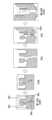
- FIG. 1is a diagram illustrating a first state (eg, an unfolded state) of an electronic device according to an embodiment.
- FIG. 2is a diagram illustrating a second state (eg, a folded state) of an electronic device according to an embodiment.
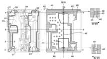
- FIG. 3is an exploded perspective view of an electronic device according to an exemplary embodiment
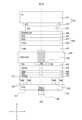
- FIG. 4is a view illustrating a front surface of a metal plate of an electronic device according to an exemplary embodiment.
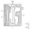
- 5Ais a cross-sectional view of an electronic device taken along line A-A', according to an exemplary embodiment.
- FIG. 5Bis a diagram illustrating a cross-section of the electronic device of FIG. 4 taken along line BB′ according to an embodiment.
- 5Cis a cross-sectional view of the electronic device of FIG. 4 taken along line C-C′ according to an embodiment.
- FIG. 6is a cross-sectional view of the electronic device of FIG. 4 taken along line A-A' according to another embodiment.
- FIG. 7is a view illustrating a front surface of a metal plate of an electronic device according to another embodiment.
- FIG. 8is a view illustrating a front surface of a hinge plate of an electronic device according to an exemplary embodiment.
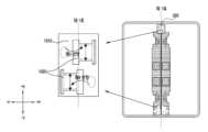
- 9Ais a diagram illustrating a hinge structure of an electronic device according to an embodiment.
- 9Bis a diagram illustrating a hinge module of a hinge structure according to an embodiment.
- FIG. 10is a diagram illustrating a hinge bracket of an electronic device according to an embodiment.
- FIG. 11is a diagram illustrating a hinge bracket of an electronic device according to an embodiment.
- FIG. 12is a diagram illustrating a hinge bracket of an electronic device according to an embodiment.
- FIG. 13is a view illustrating a protruding portion of a metal plate according to an exemplary embodiment.
- FIG. 14is a diagram illustrating a protrusion of an electronic device according to another embodiment.
- 15is a view illustrating a front surface of a metal plate of an electronic device according to an embodiment.
- 16is a diagram illustrating a protrusion of an electronic device according to another embodiment.
- 17is a diagram illustrating an electronic device in a network environment according to an embodiment.
- FIG. 1is a diagram illustrating a first state of an electronic device according to an embodiment.
- FIG. 2is a diagram illustrating a second state of an electronic device according to an embodiment.
- the electronic device 100is provided by a housing 110, a hinge cover 230 covering a foldable portion of the housing 110, and the housing 110.
- a flexible or foldable display 200(hereinafter referred to as “main display” 200) disposed within the formed space may be included.
- the surface on which the main display 200 is disposedis defined as the first surface or the front surface 101 of the electronic device 100 .
- the surface opposite to the front surface 101is defined as the second surface or the rear surface 102 of the electronic device 100 .
- a surface surrounding the space between the front surface 101 and the rear surface 102is defined as a third surface or side surface 103 of the electronic device 100 .
- the housing 110may include a foldable housing.
- the housing 110may include a first housing 111 , a second housing 112 , a first rear cover 180 , and a second rear cover 190 .
- the housing 110 of the electronic device 100is not limited to the shape and combination shown in FIGS. 1 and 2 , and may be implemented by other shapes or combinations and/or combinations of parts.
- the first housing 111 and the first rear cover 180may be integrally formed
- the second housing 112 and the second rear cover 190may be integrally formed.
- the unfolded state of the electronic device 100may mean an unfolded state 100A or a first state 100A.
- the unfolded state of the first housing 111 and the second housing 112may correspond to the unfolded state 100A or the first state 100A.
- the electronic device 100may mean a folded state 100B or a second state 100B.
- a folded state in which the second housing 1112 rotates relative to the first housing 111may correspond to a folded state 100B or a second state 100B.
- the first housing 111 and the second housing 112form different angles or distances depending on whether the electronic device 100 is in an expanded state, a folded state, or an intermediate state.
- the first housing 111 and the second housing 112are disposed on both sides around a folding axis (hereinafter referred to as “first axis”), and have a generally symmetrical shape with respect to the first axis.
- first axisa folding axis
- the first housing 111 and the second housing 112may have an asymmetrical shape in some areas.
- the second housing 112may further include a universal serial bus (USB) hole 151 .
- USBuniversal serial bus
- the first housing 111 and the second housing 112may include a part having a shape symmetrical to each other and a part having a shape asymmetrical to each other.
- the main display 200may be symmetrically disposed across the first housing 111 and the second housing 112 .
- At least a portion of the first housing 111 and the second housing 112may be formed of a metal material or a non-metal material having a rigidity of a size selected to support the main display 200 .
- the first rear cover 180may be disposed on one side of the first shaft on the back of the electronic device.
- the first rear cover 180may have a substantially rectangular periphery, and the periphery may be covered by the first housing 111 .
- the second rear cover 190may be disposed on the other side of the first shaft on the rear surface of the electronic device, and its edge may be wrapped by the second housing 112 .
- first rear cover 180 and the second rear cover 190may have substantially symmetrical shapes around a first axis.
- the first rear cover 180 and the second rear cover 190do not necessarily have symmetrical shapes, and in another embodiment, the electronic device 100 includes various shapes of the first rear cover 180 and A second rear cover 190 may be included.
- the first rear cover 180, the second rear cover 190, the first housing 111, and the second housing 112are various parts (eg, printed circuit) of the electronic device 100
- a space in which a substrate or a battery) can be disposedmay be formed.
- one or more componentsmay be disposed or visually exposed on the rear surface of the electronic device 100 .
- a portion of the sub display 220may be visually exposed through the first rear area 181 of the first rear cover 180 .
- the sub display 220may be disposed on the entire first rear area 231 of the first rear cover 180 .
- one or more parts or sensorsmay be visually exposed through the second rear area 232 of the second rear cover 190 .
- the sensormay include a proximity sensor and/or a rear camera 280 .
- the main display 200may be disposed on a space formed by the housing 110 .
- the main display 200is seated on a recess formed by the housing 110 and may form most of the front surface 101 of the electronic device 100 .
- the front surface 101 of the electronic device 100may include the main display 200, a partial area of the first housing 111 adjacent to the main display 200, and a partial area of the second housing 112.
- the rear surface 102 of the electronic device 100includes a first rear cover 180, a partial area of the first housing 111 adjacent to the first rear cover 180, a second rear cover 190, and a second A partial area of the second housing 112 adjacent to the rear cover 190 may be included.
- the main display 200may refer to a display in which at least a partial area may be transformed into a flat or curved surface.
- the main display 200includes a folding area 203 and a first display area 201 disposed on one side (the left side of the folding area 203 shown in FIG. 1) based on the folding area 203. and a second display area 202 disposed on the other side (right side of the folding area 203 shown in FIG. 1).
- the division of regions of the main display 200 shown in FIG. 1is exemplary, and the main display 200 may be divided into a plurality of (eg, four or more or two) regions according to a structure or function.
- the area of the main display 200may be divided by the folding area 203 extending parallel to the y-axis or the first axis (folding axis), but in another embodiment Areas of the main display 200 may be divided based on another folding area (eg, a folding area parallel to the x-axis) or another folding axis (eg, a folding axis parallel to the x-axis).
- the first display area 201 and the second display area 202may have generally symmetrical shapes around the folding area 203 .
- the second display area 202may include the camera hole 150, but may have a shape symmetrical to that of the first display area 201 in other areas.
- the first display area 201 and the second display area 202may include portions having symmetrical shapes and portions having shapes asymmetrical to each other.
- the camera hole 150may be visually exposed to the outside of the electronic device 100 . According to another embodiment, the camera hole 150 may be disposed below the main display 200 and not visually exposed.
- the first housing 111 and the second housing 112form an angle of 180 degrees and move in the same direction. can be placed facing up.
- the surface of the first display area 201 of the main display 200 and the surface of the second display area 202form 180 degrees to each other and may face the same direction (eg, the front direction of the electronic device).
- the folding area 203may form the same plane as the first display area 201 and the second display area 202 .
- the first housing 111 and the second housing 112may face each other.
- the surface of the first display area 201 of the main display 200 and the surface of the second display area 202form a narrow angle (eg, between 0 degrees and 10 degrees) and may face each other.
- At least a portion of the folding region 203may be formed of a curved surface having a predetermined curvature.
- the first housing 111 and the second housing 112may be disposed at a certain angle to each other.
- the surface of the first display area 201 of the main display 200 and the surface of the second display area 202may form an angle greater than that of the folded state and smaller than that of the unfolded state.
- At least a portion of the folding region 203may be formed of a curved surface having a predetermined curvature, and the curvature at this time may be smaller than that in a folded state.
- FIG. 3is an exploded perspective view of an electronic device according to an exemplary embodiment
- the electronic device 100includes a display unit 20, a bracket assembly 30, a board unit 400, a first housing 111, a second housing 112, and a first housing 111. It may include a first rear cover 180 and a second rear cover 190 .
- the display unit 20may be referred to as a display module or a display assembly.
- the display unit 20may include a main display 200 and one or more plates or layers (not shown) on which the main display 200 is seated.
- the platemay be disposed between the main display 200 and the bracket assembly 30 .
- the main display 200may be disposed on at least a part of one side of the plate (eg, the upper side with respect to FIG. 3 ).
- the platemay be formed in a shape corresponding to that of the main display 200 .
- the bracket assembly 30includes a bracket 310 including a first bracket 311 and a second bracket 312, a hinge structure 300 disposed between the first bracket 311 and the second bracket 312, A hinge cover 330 covering the hinge structure 300 when viewed from the outside, and a wiring member 343 (eg, a flexible printed circuit board (FPC)) crossing the first bracket 311 and the second bracket 312 , or a flexible printed circuit board (FPCB)).
- a wiring member 343eg, a flexible printed circuit board (FPC)
- the bracket assembly 30may be formed within the housing 110 .
- the first bracket 311may be formed within the first housing 111 and the second bracket 312 may be formed within the second housing 112 .
- the hinge cover 330may be disposed between the first housing 111 and the second housing 112 to cover internal parts (eg, the hinge structure 300). can In one embodiment, the hinge cover 330, depending on the state (flat state 100A or folded state 100B) of the electronic device 100, the first housing 111 and It may be covered by a part of the second housing 112 or exposed to the outside.
- the hinge cover 330when the electronic device 100 is in an unfolded state 100A, the hinge cover 330 may not be exposed because it is covered by the first housing 111 and the second housing 112. there is.
- the hinge cover 330when the electronic device 100 is in a folded state 100B (eg, a fully folded state), the hinge cover 330 includes the first housing 111 and the second 2 may be exposed to the outside between the housings 112.
- the hinge cover 330is the first housing 111 And between the second housing 112 may be partially exposed to the outside.
- the exposed areamay be smaller than the completely folded state.
- the hinge cover 330may include a curved surface.
- the bracket assembly 30may be disposed between the main display 200 and the substrate unit 400 .
- the first bracket 311may be disposed between the first display area 201 of the main display 200 and the first substrate 401 .
- the second bracket 312may be disposed between the second display area 202 of the main display 200 and the second substrate 402 .
- the wiring member 343 and the hinge structure 300may be disposed inside the bracket assembly 30 .
- the wiring member 343may be disposed in a direction (eg, an x-axis direction) crossing the first bracket 311 and the second bracket 312 .
- the wiring member 343is disposed in a direction (eg, the x-axis direction) perpendicular to the folding axis (eg, the y-axis or the folding axis (first axis) of FIG. 2 ) of the folding area 203 of the electronic device 100. It can be.
- the substrate unit 400may include a first substrate 401 disposed on the side of the first bracket 311 and a second substrate 402 disposed on the side of the second bracket 312.
- the first substrate 401 and the second substrate 402include a bracket assembly 30, a first housing 111, a second housing 112, a first rear cover 180 and a second rear cover 190. ) can be placed inside the space formed by
- components for realizing various functions of the electronic device 100may be mounted on the first board 401 and the second board 402 .
- the first substrate 401may be formed of a plurality of substrates.
- the first substrate 401may be formed in a form in which a plurality of substrates are separated.
- the first board 401may be formed by being separated into a first printed circuit board 403 and a second printed circuit board 404 .
- the first housing 111 and the second housing 112may be assembled to each other to be coupled to both sides of the bracket assembly 30 while the display unit 20 is coupled to the bracket assembly 30 .
- the first housing 111 and the second housing 112can be coupled to the bracket assembly 30 by sliding on both sides of the bracket assembly 30 .
- the first housing 111may include a first rotation support surface 113
- the second housing 112may include a second rotation support surface corresponding to the first rotation support surface 113 ( 114) may be included.
- the first rotation support surface 113 and the second rotation support surface 114may include a curved surface corresponding to the curved surface included in the hinge cover 330 .
- the first rotation support surface 113 and the second rotation support surface 114when the electronic device 100 is in an unfolded state (100A) (eg, the electronic device of FIG. 1), the hinge cover 330 is covered so that the hinge cover 330 is not exposed or minimally exposed to the back of the electronic device 100 . Meanwhile, the first rotation support surface 113 and the second rotation support surface 114 are attached to the hinge cover 330 when the electronic device 100 is in a folded state 100B (eg, the electronic device of FIG. 2 ).
- the hinge cover 330may be maximally exposed to the rear surface of the electronic device 100 by rotating along the included curved surface.
- the electronic device 100may further include a first battery 451, a second battery 452, and a speaker module 453.
- the first battery 451 and the second battery 452may be mounted inside the housing 110 of the electronic device 100 and not exposed to the outside.
- the first battery 451may be mounted inside the first housing 111 .
- the second battery 452may be mounted inside the second housing 112 .
- the first battery 451 and the second battery 452are a wiring member 343 (eg, a flexible printed circuit board) disposed between the first housing 111 and the second housing 112. can be electrically connected by
- the speaker module 453may be disposed inside the first housing 111 .
- the speaker module 453may be disposed in a region adjacent to the first battery 451 inside the first housing 111 .
- the speaker module 453may not be exposed to the outside of the electronic device 100 .
- the speaker module 453may be mounted on the second printed circuit board 404 of the first board 401 .
- FIG. 4is a view illustrating a front surface of a metal plate of an electronic device according to an exemplary embodiment.
- the electronic device 100may include a bracket 310 and a metal plate 410 formed in a housing 110 and a hinge structure 300 . According to an embodiment, the electronic device 100 may further include a main display ( 200 in FIG. 3 ).
- the bracket 310may include a first bracket 311 and a second bracket 312 .
- the first bracket 311may be formed within the first housing 111 and the second bracket 312 may be formed within the second housing 112 .
- first bracket 311 and the second bracket 312may be connected by a hinge structure 300 .
- the hinge structure 300may be disposed between the first bracket 311 and the second bracket 312 to physically connect the first bracket 311 and the second bracket 312 .
- the bracket 310may include a front part 313 and a side part 314 facing the front of the electronic device 100 .
- a metal plate 410may be disposed on the front portion 313 of the bracket 310.
- the metal plate 410may be attached to a waterproof tape 500 disposed on the front portion 313 of the bracket 310 and described below.
- the main display 200may be disposed on the metal plate 410 .
- the front portion 313 of the bracket 310may support the metal plate 410 and the main display 200 .
- the side portion 314 of the bracket 310may be surrounded by the housing 110.
- the side portion 314 of the first bracket 311may be surrounded by the first housing 111 and the side portion 314 of the second bracket 312 may be surrounded by the second housing 112 .
- the housing 110may surround and form a part of the main display 200 disposed on the front portion 313 of the bracket 310 .
- the housing 110 of the electronic device 100 including the foldable main display 200 and The main display 200may be attached and not fixed.
- the housing 110 surrounding a part of the main display 200may surround the main display 200 while being spaced apart from the side of the main display 200 by a predetermined distance.
- the foldable main display 200may not collide with the housing 110 when folded.
- the foldable main display 200may slip toward the housing 110 when folded, the main display 200 does not collide with the housing 110. may not be
- a shearing behaviormay occur in the main display 200 due to an external impact.
- the shearing behaviormay be reduced by a protrusion 420 of a metal plate 410 disposed under the main display 200 and described below.
- a waterproof structuremay be formed in the bracket 130.
- a waterproof tape 550may be attached to the bracket 310 to form a waterproof structure.
- first waterproof tape 551may be attached to the inside of the first bracket 311 and the second waterproof tape 552 may be attached to the inside of the second bracket 312 .
- the first bracket 311 and the first metal plate 411 disposed on the front surface of the first bracket 311come into close contact with each other by means of the first waterproof tape 551, thereby forming a waterproof structure.
- the second bracket 312 and the second metal plate 412 disposed on the front surface of the second bracket 312come into close contact with each other by the second waterproof tape 552 to form a waterproof structure.
- the first waterproof tape 551 of the first bracket 311 and the second waterproof tape 552 of the second bracket 312may not be formed symmetrically with respect to the first axis.
- the first waterproof tape 551 and the second waterproof tape 552may be differently disposed according to positions of components mounted inside the first bracket 311 and the second bracket 312 .
- the metal plate 410may be disposed on the rear surface of the main display 200 .
- the metal plate 410may be disposed between the main display 200 and the bracket 310 .
- the metal plate 410may include a first metal plate 411 and a second metal plate 412 .
- the first metal plate 411may be disposed on the rear surface of the first display area 201 of the main display 200 .
- the first metal plate 411may be disposed on the first housing 111 .
- the first metal plate 411may cover at least a portion of the first housing 111 .
- the second metal plate 412may be disposed on the rear surface of the second display area 202 of the main display 200 .
- the second metal plate 412may be disposed on the second housing 112 .
- the second metal plate 412may cover at least a portion of the second housing 112 .
- the first metal plate 411 and the second metal plate 412may cover a portion of the hinge structure 300 .
- the first metal plate 411when viewed from the front surface 101 of the electronic device 100, the first metal plate 411 may cover a portion of the hinge structure 300 adjacent to the first housing 111, and the second metal plate 411 may The plate 412 may cover a portion of the hinge structure 300 adjacent to the second housing 112 .
- the metal plate 410may include a plurality of edges 440 .
- the first metal plate 411may include a first edge 441 and the second metal plate 412 may include a second edge 442 .
- first edge 441 of the first metal plate 411 and the second edge 442 of the second metal plate 412may correspond to edges adjacent to the first axis.
- the first edge 441 and the second edge 442correspond to edges extending along a direction (eg, +y direction or -y direction) toward the first axis of the electronic device 100. It can be.
- the first edge 441 and the second edge 442may correspond to edges facing each other when the electronic device 100 is in an unfolded state 100A.
- a first axismay be formed between the first edge 441 and the second edge 442 .
- the metal plate 410may include at least one protrusion 420 and at least one recess 430 .
- the at least one protrusion 420 and the at least one recess 430may be a first edge 441 of the first metal plate 411 or a second edge of the second metal plate 412 ( 442) can be formed.
- first recess 431 and the first protrusion 421may be formed at the first edge 441 of the first metal plate 411 , and the second edge of the second metal plate 412 may be formed.
- a second recess 432 and a second protrusion 422may be formed in 442 .
- the first protrusion 421 of the first metal plate 411may extend from the first edge 441 of the first metal plate 411 .
- the first protrusion 421may be formed to extend from one area of the first edge 441 of the first metal plate 411 .
- the first protrusion 421may be formed in a region of the first metal plate 411 adjacent to the first end of the first edge 441 .
- the first protrusion 421may be formed in a region of the first edge 441 adjacent to the third edge 443 .
- the first protrusion 421may protrude in a second direction (eg, +x direction) perpendicular to the first axis.
- a second directioneg, +x direction
- the first protrusion 421may protrude and extend toward the second metal plate 412 in a second direction (eg, a +x direction).
- the second protrusion 422 of the second metal plate 412may extend from the second edge 442 of the second metal plate 412 .
- the second protrusion 422may protrude toward a third direction (eg, -x direction) opposite to the second direction (eg, +x direction).
- the second protrusion 422may protrude and extend toward the first metal plate 411 in a third direction (eg, -x direction).
- the first recess 431 of the first metal plate 411may be recessed from the first edge 441 .
- the first recess 431may be formed by being depressed in a region of the first edge 441 adjacent to the second end of the first edge 441 .
- the first recess 431may be formed by being depressed in a region of the first edge 441 adjacent to the fourth edge 444 .
- the first recess 431may be formed to be depressed in the third direction (eg, -x direction).
- the second recess 432 of the second metal plate 412may be recessed from the second edge 442 .
- the second recess 432may be formed by being depressed in a region of the second edge 442 adjacent to the first end of the second edge 442 .
- the second recess 432may be formed by being depressed in a region of the second edge 442 adjacent to the fifth edge 445 .
- the second recess 432may be recessed in the second direction (eg, +x direction).
- the first recess 431when the electronic device 100 is in the unfolded first state 100A, the first recess 431 may be depressed in a direction opposite to that of the second metal plate 412, The second recess 432 may be depressed in a direction opposite to that of the first metal plate 411 .
- the first protrusion 421may be formed to be spaced apart from the first recess 431, and the second protrusion 422 may be spaced apart from the second recess 432. can be formed
- the first protrusion 421may be formed in a region of the first edge 441 adjacent to the third edge 443 of the first metal plate 411, and the first recess 431 may be It may be formed in one area of the first edge 441 adjacent to the fourth edge 444 of the first metal plate 411 .
- the second protrusion 422may be formed in a region of the second edge 442 adjacent to the sixth edge 446 of the second metal plate 412, and the second recess 432 may be formed in one area of the second edge 442 adjacent to the fifth edge 445 of the second metal plate 412 .
- the third edge 443 of the first metal plate 411 and the fifth edge 445 of the second metal plate 412may correspond to the top edge of the electronic device 100 .
- the fourth edge 444 of the first metal plate 411 and the sixth edge 446 of the second metal plate 412may correspond to the lower edge of the electronic device 100. there is.
- the first protrusion 421when the electronic device 100 is in an unfolded state 100A, the first protrusion 421 may be recessed into the second recess 432, and the second protrusion 422 may be recessed into the first recess 432. It may be sunk into the seth 431 .
- the first recess 431 and the second recess 432may form a space capable of accommodating the second protrusion 422 and the first protrusion 421 .
- the electronic device 100is in an unfolded state 100A, the first metal plate 411 and the second metal plate (412) can be combined.
- the protrusion 420is accommodated in the corresponding recess 430 and the first metal plate 411 and the second metal plate 412 are coupled, thereby reducing the metal plate 410 by an external impact.
- the shear behavior or twist in the first axial direction (eg, +y direction or -y direction) of the metal plate 410is not formed or the first metal plate 411 and the second metal plate 412 are not coupled. may be less than if it were not.
- the shear behavior or twist of the metal plate 410decreases, the shear behavior or twist of the main display 200 disposed on the metal plate 410 in the first axial direction may also decrease.
- the electronic device 100can secure durability.
- 5Ais a cross-sectional view of an electronic device taken along line A-A', according to an exemplary embodiment.
- the electronic device 100may include a main display 200, a metal plate 410, a bracket 310, and/or a hinge structure 300. According to an embodiment, the electronic device 100 may further include a waterproof tape 550.
- the main display 200may include a plurality of layers.
- the main display 200includes a cover glass 510, a display panel 520 disposed adjacent to one surface of the cover glass 510, and/or a display panel 520 below the display panel 520. It may include a dielectric layer structure 530 disposed on.
- the main display 200is not limited to the above structure.
- some componentseg, the thermoplastic material 540
- other componentsmay be added.
- the main display 200may further include an adhesive for bonding the plurality of layers described above.
- the adhesivemay include pressure sensitive adhesive (PSA), but is not limited thereto.
- the adhesivemay include optically clear adhesive (OCA), thermally reactive adhesive, and/or double-sided tape in addition to PSA.
- the cover glass 510may include a film layer 511 and/or a transparent plate 512 .
- at least a portion of the film layer 511may be exposed to the outside through the front surface 101 of the electronic device 100 .
- the transparent plate 512may correspond to ultra-thin tempered glass, but is not limited thereto.
- the film layer 511 and the transparent plate 512may be bonded by an adhesive.
- the film layer 511 and the transparent plate 512have ductility and may be folded or bent.
- the film layer 511may be referred to as a polarization film, but is not limited thereto.
- the main display 200may include a display panel 520 disposed under the cover glass 510 .
- the display panel 520may be attached to the cover glass 510 by the first adhesive layer 561 .
- the display panel 520may include a panel 521 and/or a plastic film 522 disposed under the panel 521 .
- the panel 521may be attached to the transparent plate 512 by an adhesive (eg, PSA).
- the plastic film 522may be referred to as a polarization film.
- the panel 521may be implemented as a touch panel on which electrodes for receiving touch input, fingerprint recognition, or pen input are disposed.
- the panel 521may include an organic light emitting diodes (OLED) panel, a liquid crystal display (LCD), or a quantum, dot, light-emitting diodes (QLED) panel.
- the display panel 520includes a plurality of pixels for displaying an image, and one pixel may include a plurality of sub-pixels.
- one pixelmay include three colors of red sub-pixels, green sub-pixels, and blue sub-pixels.
- one pixelmay be formed in an RGBG pentile method including one red subpixel, two green subpixels, and one blue subpixel.
- the main display 200may include a dielectric layer structure 530 disposed below the display panel 520 .
- the dielectric layer structure 530may be attached to the display panel 520 by the second adhesive layer 562 (eg, PSA).
- the adhesive layermay be formed in a region corresponding to the dielectric layer structure 530 .
- the adhesive layer 531may be disposed to be formed on an inner region of an edge of the dielectric layer structure 530 .
- the dielectric layer structure 530may include a lattice pattern.
- the dielectric layer structure 530may include a grid pattern formed in a region adjacent to the first axis.
- the dielectric layer structure 530since the dielectric layer structure 530 includes a lattice pattern, as the electronic device 100 is folded (eg, the second state 100B) or unfolded (eg, the first state 100A), The dielectric layer structure 530 and the layers attached to the dielectric layer structure 530 (eg, the cover glass 510 and/or the metal plate 410) may also be folded or unfolded.
- the dielectric layer structure 530may include a material for securing rigidity and a material for reducing weight. According to an embodiment, the dielectric layer structure 530 may have a structure in which a layer for securing rigidity and a layer formed of a lightweight material are stacked. According to an embodiment, due to the materials included in the dielectric layer structure 530, the main display 200 can secure rigidity. According to an embodiment, as at least a portion of the dielectric layer structure 530 is formed of a lightweight material, the weight of the main display 200 may be reduced.
- the main display 200may further include a thermoplastic material 540 (eg, thermoplastic polyurethane (TPU)) disposed below the dielectric layer structure 530 .
- a thermoplastic material 540eg, thermoplastic polyurethane (TPU)
- the main display 200further includes the thermoplastic material 540, damage applied to the display panel 520, the dielectric layer structure 530, and the metal plate 410 can be prevented.
- the main display 200further includes the thermoplastic material 540 , bubbles generated between a plurality of layers disposed on the main display 200 may be prevented.
- the metal plate 410may be disposed below the main display 200 .
- the metal plate 410may be disposed below the dielectric layer structure 530 and/or the thermoplastic material 540 of the main display 200 .
- the metal plate 410may be formed by being disconnected from a region corresponding to the first axis.
- the first metal plate 411 and the second metal plate 412may be separately disposed based on the first axis.
- the first metal plate 411 and the second metal plate 412are disconnected and disposed with respect to the first axis, so that when the electronic device 100 is folded or unfolded, the metal plate ( 410) can be folded or unfolded.
- a portion of the metal plate 410may be formed transverse to the folding axis by including ductility.
- a region corresponding to the first axis of the flexible metal plate 410may be formed as flexible, and the remaining region may be formed as a metal member.
- the metal plate 410may be referred to as a shielding layer.
- the metal plate 410may reduce noise by shielding magnetic force due to peripheral electronic components in addition to signals input from the electronic pen.
- the metal plate 410may be formed of a metal member.
- the metal plate 410may be formed of a copper alloy, but is not limited thereto.
- the metal plate 410may be formed of stainless use steel (SUS).
- the first metal plate 411may include a first protrusion 421 .
- the first protrusion 421 of the first metal plate 411is formed, so that when viewed on a first plane (eg, xz plane), the second axis (eg, xz plane) of the first metal plate 411 is formed.
- the first length L1 in the x-axis directionmay be longer than the second length L2 of the second metal plate 412 in the second axial direction.
- the first metal plate 411has a first axis relative to the first axis when viewed from a first plane (eg, an xz plane). It may be formed by protruding in two directions (eg, +x direction).
- the second metal plate 412is provided with a second recess (432 in FIG. 4 ) accommodating the first protrusion 421 , so that the second metal plate 412 is formed in a first plane (eg, an xz plane). When viewed, it may be formed spaced apart in a second direction (eg, +x direction) based on the first axis.
- the second length L2 of the second metal plate 412is the first length of the first metal plate 411 ( L1) may be formed longer.
- the first metal plate 411moves in a third direction (eg, -x direction) based on the first axis. It can be formed spaced apart.
- the protrusion 420 and the recess 430are formed on the metal plate 410, so that when the electronic device 100 is in an unfolded state (100A, first state), the first metal plate ( 411) and the second metal plate 412 may be coupled.
- each of the protrusions 420is drawn into the corresponding recess 430, so that the first metal plate ( 411) and the second metal plate 412 may be coupled and fixed in the first axis direction (eg, +y direction or -y direction).
- the first axial direction (eg, +y direction or -y direction) of the metal plate 410 by external impact direction) or torsionmay be reduced.
- the shear behavior or twist of the metal plate 410decreases, the first axis direction (eg, +y direction or -y direction) of the main display 200 disposed on the metal plate 410 ), the shear behavior or torsion may also be reduced. Accordingly, durability of the main display 200 may be increased.
- the main display 200may omit the cover panel or include a cover panel having a thin thickness. .
- the production cost and production time of the electronic device 100can be reduced.
- the visibility of the main display 200 of the electronic device 100may be improved by reducing wrinkles of the folding portion of the main display 200 due to the thin cover panel.
- the bracket 310may be disposed below the metal plate 410 .
- the first bracket 311may be disposed below the first metal plate 411 and the second bracket 312 may be disposed below the second metal plate 412 .
- the bracket 310may be disposed under the cover glass 510 or the display panel 520 and extend to the side.
- the bracket 310may be formed to surround a portion of a side surface of the cover glass 510 or the display panel 520 .
- the bracket 310may extend apart from the side surface of the cover glass 510 or the display panel 520 with a predetermined gap.
- the bracket 310may be formed to be spaced apart from the side of the main display 200 with a predetermined gap.
- the bracket 310forms a certain gap with the side surface of the cover glass 510 or the display panel 520, when the electronic device 100 is folded, the side surface of the main display 200 and the bracket The collision of (310) can be prevented.
- the main display 200may slip to the side and may not collide with the bracket 310 despite the main display 200 slipping.
- the formation of the bracket 310 on the side of the main display 200has been described as an example, but is not limited thereto.
- the housing 110may be formed with a predetermined gap on the side of the main display 200 .
- another configurationmay be added between the bracket 310 and the metal plate 410.
- a waterproof tape 550may be further added between the bracket 310 and the metal plate 410 .
- the brackets 310may be disposed in both directions around the hinge structure 300 .
- the first bracket 311may be disposed in a third direction (eg, -x direction) with respect to the hinge structure 300
- the second bracket 312may be disposed with respect to the hinge structure 300. It may be disposed in the second direction (eg, +x direction).
- the metal plate 410may be attached on the bracket 310 by an adhesive part.
- the adhesive portionmay correspond to a waterproof member (hereinafter, “waterproof tape 550”), but is not limited thereto.
- the bonding portionmay correspond to a waterproof bond.
- the waterproof tape 550may be disposed between the metal plate 410 and the bracket 310.
- the first waterproof tape 551may be disposed between the first metal plate 411 and the first bracket 311
- the second waterproof tape 552may be disposed between the second metal plate 412 and the first bracket 311. 2 may be disposed between the brackets (312).
- the first waterproof tape 551may be disposed below the first metal plate 411
- the second waterproof tape 552may be disposed below the second metal plate 412 .
- the waterproof tape 550may be disposed in a first area adjacent to the first axis and in a second area spaced apart from the first area and adjacent to the ends of the bracket 310 and the metal plate 410. .
- a portion of the waterproof tape 550may be adjacent to the hinge structure 300 and another portion of the waterproof tape 550 may be disposed spaced apart from the hinge structure 300 .
- the first waterproof tape 551 disposed under the first metal plate 411includes a first area adjacent to the first axis and spaced apart from the first area and adjacent to the end of the first metal plate 411. It can be placed in the second area.
- the first waterproof tape 551 disposed under the second metal plate 412may include a first area adjacent to the first axis and spaced apart from the first area and an end of the first metal plate 411. It may be disposed in the second area adjacent to.
- the waterproof tape 550is disposed so that the waterproof function of the electronic device 100 as well as the main display 200 and/or the metal plate 410 is protected on the bracket 310. can be fixed.
- the shear behavior of the main display 200is such that the waterproof tape 550 is applied only to the second region spaced apart from the first axis. If formed, it may occur larger.
- the shear behavior of the main display 200is formed as a single housing. may occur in larger cases.
- the increase in the shear behavior of the main display 200 by the separated housing 110 and the waterproof tape 550is caused by the protrusion 420 and the recess 430 on the metal plate 410. formation can be reduced.
- the metal plate 410caused by an external impact Shear behavior or twist in the first axis direction (eg, +y direction or -y direction) of may be reduced.
- the shearing behavior or twisting of the metal plate 410 in the first axis directiondecreases.
- the shearing behavior or twisting of the main display 200may decrease.
- the hinge structure 300may be disposed in an area corresponding to the first axis.
- the hinge structure 300may be disposed on the folding unit.
- the first axismay refer to a central axis of the hinge structure 300, but is not limited thereto.
- the first axismay be an axis partially spaced from the center of the hinge structure 300 in a second direction (eg, +x direction) or a third direction (eg, -x direction).
- the electronic device 100may be folded or unfolded by the hinge structure 300 around the first axis.
- the second housing 112may rotate with respect to the first housing 111 of the electronic device 100 by the hinge structure 300 around the first axis.
- hinge structure 300will be described later in FIGS. 8, 9A, 9B, and 10 to 13.
- FIG. 5Bis a diagram illustrating a cross-section of the electronic device of FIG. 4 taken along line BB′ according to an embodiment.
- the electronic device 100 of FIG. 5Bmay further include a lower material 571 unlike the electronic device 100 of the AA' section of FIG. 5A.
- plane B-B' in FIG. 5Bcorresponds to the center area of the hinge structure 300 through which the wiring member (343 in FIG. 3 ) passes, and thus, plane A-A' in FIG. 5A Unlike the metal plate 410 , the metal plate 410 of FIG. 5B may not include the protrusion 420 and the recess 430 .
- a waterproof tape 550 and a lower material 571may be further disposed between the metal plate 410 and the bracket 310 .
- the waterproof tape 550may be disposed in a first area adjacent to the first axis and in a second area spaced apart from the first area and adjacent to ends of the bracket 310 and the metal plate 410 .
- the lower material 571may be disposed in an area more adjacent to the first axis than the first area.
- the lower material 571may be disposed below the metal plate 410 .
- the lower material 570may include a first lower material 571 and a second lower material 572, and the first lower material 571 is below the first metal plate 411. and the second lower material 572 may be disposed below the second metal plate 412 .
- the first lower material 571may correspond to a shielding sheet, and the shielding sheet may be formed in a partial area under the metal plate 410 corresponding to the hinge structure 300 .
- the lower material 571has been described as being applicable to a shielding sheet, but is not limited thereto.
- the lower material 571may correspond to graphite or cushion.
- 5Cis a cross-sectional view of the electronic device of FIG. 4 taken along line C-C′ according to an embodiment.
- the protrusion 420 on the metal plate 410 of FIG. 5Cmay be formed in a direction opposite to that of the protrusion 420 on the metal plate 410 of FIG. 5A.
- the protrusion 420 of the second metal plate 412 of FIG. 5Cmay be formed toward a third direction (eg, -x direction).
- the electronic device 100 of FIG. 5Cmay include only one first lower material 571 unlike the electronic device 100 of FIG. 5B having a BB′ cross section.
- a lower material 570 and a waterproof tape 550may be formed below the first metal plate 411, but the lower material 570 is omitted below the second metal plate 412. and only the waterproof tape 550 may be formed.
- a first lower material 571 and a first waterproof tape 551may be disposed below the first metal plate 411, and a second waterproof tape ( 552) may be placed.
- the first waterproof tape 551 at the C-C' cross sectionmay be formed in one line. there is.
- the second waterproof tape 552may be formed in one or more lines.
- the first waterproof tape 551 disposed below the first metal plate 411is thicker than the second waterproof tape 552 disposed below the second metal plate 412. It can be. According to one embodiment, as the thickness of the first waterproof tape 551 is thicker than the thickness of the second waterproof tape 552, one line of the first waterproof tape ( 551), the first metal plate 411 may be fixed on the first bracket 311 with substantially the same adhesive strength as that of the second metal plate 412.
- the lower material 570 of FIG. 5cmay be substantially the same as the lower material 570 of FIG. 5b.
- the electronic device 100includes a cover panel, a damping layer, and/or A digitizer may be further included.
- FIG. 6is a cross-sectional view of the electronic device of FIG. 4 taken along line A-A' according to another embodiment.
- the main display 200 of FIG. 6is the main display further including the damping layer 630, the cover panel 610, and/or the digitizer 620 in the main display 200 of FIGS. 5A to 5C. (200) may be applicable.
- a damping layer 630may be formed under the cover glass 510 .
- the damping layer 630may be disposed between the cover glass 510 and the display panel 520 .
- the damping layer 630may be attached to the cover glass 510 by the first adhesive layer 561, and the panel 521 of the display panel 520 by the second adhesive layer 651 (PSA2). ) can be attached.
- the cover panel 610may be disposed below the display panel 520 . According to an embodiment, the cover panel 610 may be attached to the dielectric layer structure 530 by an adhesive (eg, PSA).
- PSAan adhesive
- the cover panel 610may be disposed across the first axis.
- the cover panel 610may be formed in a region corresponding to the dielectric layer structure 530, but is not limited thereto.
- the cover panel 610may be disposed to be formed on an inner region of an edge of the dielectric layer structure 530 .
- one area of the cover panel 610 corresponding to the first axishas a thinner thickness in one direction (eg, z direction) than another area of the cover panel 610 spaced apart from the first axis. can be formed According to an embodiment, the thickness of one area of the cover panel 610 corresponding to the first axis is formed thin, so that the main display 200 can be folded or unfolded.
- the cover panel 610may increase the rigidity of the main display 200 .
- the cover panel 610may block propagation of the shearing or distortion to the display panel 520 .
- shearing or distortion of the display panel 520is prevented, thereby increasing the rigidity of the main display 200 .
- the electronic device 100 of FIG. 6may include a cover panel 610 whose thickness is reduced compared to an electronic device that does not include the protrusion 420 and the recess 430 .
- the first metal plate 411 and the second metal plate 412are formed in the first state 100A by the protrusion 420 and the recess 430 . ) is coupled, shear behavior or distortion of the metal plate 410 in the first axial direction (eg, +y direction or -y direction) due to external impact may be reduced.
- the electronic device 100since the shearing behavior or distortion is reduced by the metal plate 410 having the protrusion 420 and the recess 430, the electronic device 100 has the protrusion 420 and the recess 430. It may further include a cover panel 610 whose thickness is reduced compared to the electronic device that does not include it.
- the thickness of the cover panel 610by reducing the thickness of the cover panel 610, cost and time for producing the electronic device 100 can be saved, and the electronic device 100 has a wrinkle-improved main display 200.
- cost and time for producing the electronic device 100can be saved, and the electronic device 100 has a wrinkle-improved main display 200.
- the thermoplastic material 540 of FIG. 6may be formed under a portion of the dielectric layer structure 530 corresponding to the first axis. In one example, the thermoplastic material 540 may be disposed under the lattice pattern of the dielectric layer structure 530 .
- the digitizer 620may be disposed under the dielectric layer structure 530 or the thermoplastic material 540 .
- digitizer 620may be attached to dielectric layer structure 530 by third adhesive layer 652 .
- a region of the digitizer 620 corresponding to the first axismay be formed by being disconnected.
- the first area of the digitizer 620may be disposed on the first metal plate 411 and the second area of the digitizer 620 may be disposed on the second metal plate 412 .
- the digitizer 620since the digitizer 620 is formed separately in an area corresponding to the first axis, when the electronic device 100 is folded or unfolded, the digitizer 620 can be folded or unfolded without damage.
- the digitizer 620is a device capable of detecting an input for an x position and/or a y position, and may detect a magnetic field type input device (eg, an electronic pen).
- a magnetic field type input deviceeg, an electronic pen
- at least one processoreg, the processor 1720 of FIG. 17
- the digitizer 620may generate an electromagnetic field.
- an electromagnetic induction phenomenonoccurs and a resonant circuit of the electronic pen may generate current.
- the resonant circuit of the electronic penmay form a magnetic field using the generated current.
- At least one processormay detect the location by scanning the strength of the magnetic field applied from the electronic pen to the digitizer 620 over the entire area. At least one processor may perform an operation based on the detected location.
- a shielding sheet 640(eg, copper sheet, Cu sheet) may be formed under the digitizer 620 .
- the shielding sheet 640may be formed in an area corresponding to the digitizer 620 .
- the shielding sheet 640may be formed separately in an area corresponding to the first axis.
- the shielding sheet 640may be attached to the metal plate 410 by the fourth adhesive layer 653 .
- the metal plate 410 of FIG. 6may be substantially the same as the metal plate 410 of FIGS. 4 and 5A to 5C.
- FIG. 7is a view illustrating a front surface of a metal plate of an electronic device according to another embodiment.
- the electronic device 100 of FIG. 7may correspond to the electronic device 100 omitting the waterproof tape 550 of FIGS. 5A to 5C or FIG. 6 .
- the dielectric layer structure 530may be attached to the bracket 310 by the fourth adhesive layer 720 .
- the fourth adhesive layer 720may be disposed on the edges of the dielectric layer structure 530 and the bracket 310 .
- the fourth adhesive layer 720may be disposed on a region on the bracket 310 spaced apart from the first axis.
- the fourth adhesive layer 720since the fourth adhesive layer 720 is spaced apart from the first axis, a space may be formed between the dielectric layer structure 530, the bracket 310, and the hinge structure 300. In other words, according to an embodiment, the fourth adhesive layer 720 is spaced apart from the first axis, so that the fourth adhesive layer 720, the dielectric layer structure 530, the bracket 310, and the hinge structure 300 are surrounded.
- the thermoplastic material 540, the metal plate 410, and the cushion member 730may be disposed in the space.
- thermoplastic material 540a thermoplastic material 540, a metal plate 410, and/or a cushion member 730 may be disposed in the space.
- thermoplastic material 540may be disposed under the dielectric layer structure 530 .
- a metal plate 710may be disposed below the thermoplastic material 540 .
- the metal plate 710 of FIG. 7may correspond to substantially the same plate as the metal plate 410 of FIG. 4 . That is, the description of the metal plate 410 of FIG. 4 may also be applied to the metal plate 710 of FIG. 7 .
- thermoplastic material 740 and the metal plate 710 of FIG. 7are similar to the thermoplastic material 540 and the metal plate 410 of FIGS. 4, 5A to 5C, and 6 described above. Substantially the same thermoplastic material and metal plate may correspond.
- the metal plate 410 of FIG. 7includes a protrusion and a recess, so that the metal plate 410 and the main display 200 due to external impact are moved in the first axis direction (eg, +y direction or -y direction). y-direction), shearing behavior or twisting can be prevented.
- a cushion member 730may be disposed below the metal plate 410 .
- each cushion member 730may be disposed between the metal plate 410 , the hinge structure 300 and the bracket 310 .
- the cushion member 730may be formed by being disconnected from a region corresponding to the first axis. According to an embodiment, since the cushion member 730 is formed by being disconnected in an area corresponding to the first axis, the cushion member 730 may be folded or unfolded based on the first axis.
- the cushion member 730is disposed below the metal plate 410, so that the electronic device 100 is connected to the metal plate 410 and the hinge structure ( 300) can be prevented from colliding.
- the cover glass 510may further include a polarizer 750.
- the polarizer 750may be disposed between the transparent plate 512 and the panel 525 .
- the polarizer 750may be attached to the transparent plate 512 by an adhesive layer (eg, PSA).
- FIG. 8is a view illustrating a front surface of a hinge plate of an electronic device according to an exemplary embodiment.
- the electronic device 100includes a housing 110 constituting the exterior of the electronic device 100, a bracket 310 disposed in the housing 110 and mounting a plurality of electronic components, and the electronic device 100 ) It may include a hinge structure 300 for rotating the housing 110.
- the hinge structure 300may be disposed in an area corresponding to a first axis (eg, a folding axis).
- a first axiseg, a folding axis
- the central axis of the hinge structure 300may correspond to the first axis, but is not limited thereto.
- the hinge structure 300may be folded or unfolded around a first axis. Through this, the electronic device 100 may switch between a folded state 100B and an unfolded state 100A.
- the hinge structure 300may be connected to the first housing 111 and the second housing 112 .
- the hinge structure 300may connect the first housing 111 and the second housing 112 such that the second housing 112 is rotatable about a first shaft with respect to the first housing 111 .
- the hinge structure 300may be connected to a first bracket 311 fixed in the first housing 111 and a second bracket 312 fixed in the second housing 112 .
- the hinge structure 300is connected to the first bracket With respect to (311)
- the second bracket 312may be rotatable around the first axis.
- the bracket 310 including the first bracket 311 and the second bracket 312may be disposed on both sides of the hinge structure 300 within the housing 110 .
- the first bracket 311is disposed in a third direction (eg, -x direction) with respect to the hinge structure 300
- the second bracket 312is disposed in a second direction (eg, +x direction) can be placed in
- a first battery 451 and/or a speaker module 453may be disposed in the first bracket 311, and a second battery 452 may be mounted in the second bracket 312. It can be.
- the bracket 310may be physically connected to the hinge structure 300 described above. Therefore, according to one embodiment, the bracket 310 by the hinge structure 300 can be rotated based on the first axis.
- the second bracket 312may be rotatable about the first axis with respect to the first bracket 311 by the hinge structure 300 .
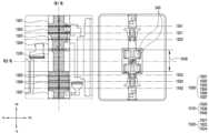
- 9Ais a diagram illustrating a hinge structure of an electronic device according to an embodiment.
- the hinge structure 300 of the electronic device 100includes a hinge module 920 connected to the first housing 111 and the second housing 112, and the electronic device 100 can be folded or unfolded. At least one hinge gear 910 that rotates so as to rotate, a hinge plate 960 covering at least a portion of the hinge module 920 and the hinge gear 910, and supporting at least one component of the hinge structure 300 A fixing screw 990 coupling the hinge cover 330 and/or the hinge gear 910 and the hinge module 920 and the hinge cover 330 may be included.
- the hinge cover 330may support the hinge module 920 and the hinge gear 910 .
- the hinge module 920 and the hinge gear 910are disposed on the hinge cover 330, so that the hinge cover 330 includes the hinge module 920 and the hinge gear 910. can support
- one surface of the hinge cover 330may be exposed to the outside when the electronic device 100 is in the second state 100B.
- one surface of the hinge cover 330is exposed to the outside between the first housing 111 and the second housing 112.
- the hinge cover 330may be formed of a conductive member.
- the hinge cover 330may be formed of a metal member (stainless use steel). However, it is not limited thereto, and a part of the hinge cover 330 may include a non-conductive member.
- At least one hinge gear 910may correspond to a component that determines an angle at which the electronic device 100 is folded or unfolded.
- At least one hinge gear 910may be disposed in an area corresponding to the first axis. According to an embodiment, by rotating the hinge gear 910, the electronic device 100 may switch between a folded state 100B and an unfolded state 100A.
- At least one hinge gear 910may be formed symmetrically up and down with respect to the second axis.
- the first hinge gear 911may be disposed in a direction from the second axis of the electronic device 100 to the top of the electronic device 100 (eg, +y direction).
- the first hinge gear 911may be disposed in a region on the first axis adjacent to the camera hole ( 150 in FIG. 1 ).
- the second hinge gear 912may be disposed in a direction from the second axis of the electronic device 100 to the bottom of the electronic device 100 (eg, -y direction).
- the second hinge gear 912may be disposed in a region on the first axis adjacent to the USB hole (eg, the USB hole 151 of FIG. 1 ).
- the first hinge gear 911 and the second hinge gear 912may be fixed on the hinge cover 330 by a fixing screw 990 .
- the hinge plate 960may correspond to a plate disposed on front surfaces of the hinge gear 910 , the hinge module 920 , and the hinge cover 330 .
- a portion of hinge plate 960may be disposed on hinge gear 910 .
- a portion of the hinge plate 960may be disposed on substantially the same plane as the hinge gear 910 (eg, an xy plane), but is not limited thereto.
- a portion of the hinge plate 960may be disposed on the hinge gear 910 forming a plurality of layers.
- the hinge plate 960may be disposed in front of the hinge gear 910 and the hinge cover 330 to protect the hinge gear 910 and/or the hinge cover 330 .
- the hinge module 920may be connected to the hinge gear 910.
- a part of the hinge module 920may be folded or unfolded around the first axis by being physically connected to the hinge gear 910 .
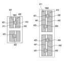
- 9Bis a diagram illustrating a hinge module of a hinge structure according to an embodiment.
- FIG. 9Bis a view showing only the hinge module 920 of the hinge structure 300 .
- the hinge module 920may include a first hinge module 921 , a second hinge module 922 , a third hinge module 923 , and a fourth hinge module 924 .
- the first hinge module 921 and the second hinge module 922may be disposed in an upper area of the electronic device 100 .
- the first hinge module 921 and the second hinge module 922may be disposed in one area on the first axis adjacent to the camera hole ( 150 in FIG. 1 ) of the electronic device 100 .
- the third hinge module 923 and the fourth hinge module 924may be disposed in a lower area of the electronic device 100 .
- the third hinge module 923 and the fourth hinge module 924may be disposed in one area on the first axis adjacent to the USB hole ( 151 in FIG. 1 ) of the electronic device 100 .
- the hinge module 920may be formed left-right symmetrically with respect to the first axis.
- the first hinge module 921 and the third hinge module 923may be disposed in a second direction (eg, +x direction) with respect to the first axis.
- the second hinge module 922 and the fourth hinge module 924may be disposed in a third direction (eg, -x direction) with respect to the first axis.
- first hinge module 921 and the second hinge module 922may be formed symmetrically with respect to the first axis
- the third hinge module 923 and the fourth hinge module 924may be formed left-right symmetrically with respect to the first axis.
- the hinge module 920may be formed vertically symmetrically with respect to the second axis.
- the third hinge module 923 and the fourth hinge module 924may be formed symmetrically with the first hinge module 921 and the second hinge module 922 with respect to the second axis. there is.
- first hinge module 921 and a portion of the second hinge module 922may be formed asymmetrically with respect to the first axis.
- first hinge module protrusion 941may be formed in the first hinge module 921
- second hinge module recess 952may be formed in the second hinge module 922 .
- a part of the first hinge module 921may be formed asymmetrically with a part of the third hinge module 923 based on the second axis.
- the first hinge module protrusion 941may be formed on a part of the first hinge module 921
- the first hinge module recess 951may be formed on a part of the second hinge module 922. .
- a part of the hinge module 920may be connected to the housing 110 of the electronic device 100.
- the first hinge module 921 and the third hinge module 923may be connected to the first housing 111 or the first bracket 311 fixed within the first housing 111 .
- connection relationship between the hinge module 920 and the housing 110has been described only for the first hinge module 921, but is not limited thereto.
- a part of the second hinge module 922is connected to the first hinge gear 911, and another part of the second hinge module 922 is connected to the second housing 112 or the second bracket 312. can be connected
- connection relationship between the hinge module 920 and the housing 110may also be applied to the third hinge module 923 and the fourth hinge module 924 .
- the hinge gear 910 and the hinge module 920are connected, as the hinge gear 910 rotates based on the first axis, the hinge module 920 can rotate based on the first axis. .
- the hinge module 920may include at least one hinge module protrusion 940 and at least one hinge module recess 950 .
- the first hinge module 921may include a first hinge module protrusion 941 extending toward the second hinge module 922 when the electronic device 100 is in the unfolded state 100A.
- the second hinge module 922is depressed in a direction opposite to the direction in which the first hinge module 921 is located when the electronic device 100 is in an unfolded state (100A), and the first hinge module protrusion and a second hinge module recess 952 for receiving 941 .
- the hinge module 920 in which the hinge module protrusion 940 and the hinge module recess 950 are formedhas been described as the first hinge module 921 and the second hinge module 922, but is not limited thereto.
- the third hinge module 923may include a first hinge module recess 951 and the fourth hinge module 924 may include a second hinge module protrusion 942 .
- the hinge module 920when viewed from the front surface 101 of the electronic device 100, may overlap a portion of the metal plate 410.
- the first hinge module 921is a first hinge module protrusion 941 overlapping the first protrusion 421 of the first metal plate 411 when viewed from the front surface 101 of the electronic device 100.
- the second hinge module 922may include a second hinge module recess overlapping the second recess 432 of the second metal plate 412 when viewed from the front surface 101 of the electronic device 100 ( 952) may be included.
- the third hinge module 923overlaps the first recess 431 of the first metal plate 411 when viewed from the front surface 101 of the electronic device 100. Seth 951 may be included.
- the fourth hinge module 924is a second hinge module protrusion overlapping the second protrusion 422 of the second metal plate 412 when viewed from the front surface 101 of the electronic device 100 ( 942) may be included.
- the hinge module protrusion 940 and the hinge module recess 950may be formed in numbers and shapes corresponding to those of the protrusion 420 and the recess 430 of the metal plate 410 .
- the first hinge module 921 and/or the third hinge module 923have A first hinge module protrusion 941 and/or a third hinge module protrusion (not shown) may be formed.
- the hinge module protrusion 940 and the hinge module recess 950are further formed so that the metal plate 410 and the hinge module 920 due to external impact are moved in the first axial direction (eg, + The shear behavior or twisting in the y direction or -y direction) can be reduced.
- the electronic device 100can prevent the main display 200 from being damaged.
- the cover panel (cover panel 610 of FIG. 6 ) of the electronic device 100may be omitted. According to one embodiment, as the cover panel 610 is omitted, cost and time for producing the electronic device 100 can be saved.
- FIG. 10is a diagram illustrating a hinge bracket of an electronic device according to an embodiment.
- the hinge structure 300may further include a hinge bracket 1010.
- the hinge bracket 1010may be disposed on the rear surface of the hinge module 920 when the electronic device 100 is in an unfolded state 100A.
- the hinge bracket 1010is the back surface of the first hinge module 921 and the second hinge module 922 and/or the third hinge module 923 ) and the rear surface of the fourth hinge module 924.
- the hinge bracket 1010is the hinge module of the hinge module 920.
- a guide hall 1020 for guiding the protruding portion 940 and the protruding portion 420 of the metal plate 410 to rotate in a certain directionmay be formed.
- the metal plate 410 and/or the hinge module 920may rotate in a third direction (eg, clockwise direction) or a fourth direction (eg, counterclockwise direction) of FIG. 10 .
- the protruding portion 420 or the hinge module protruding portion 940is drawn into the guide hole 1020 to form the third direction. It can rotate in a certain direction.
- the guide hole 1020is the first protrusion 421 drawn into the guide hole 1020.
- the first hinge module protrusion 941may be guided to rotate constantly in the third direction.
- the metal plate 410 and/or the hinge module 920has been described as rotating in the third direction, it is not limited thereto and the metal plate 410 and/or the hinge module 920 may rotate in the fourth direction.
- the guide hole 1020extends through the protrusion 420 and/or the hinge drawn into the guide hole 1020.
- the module protrusion 940may be guided to rotate constantly in the fourth direction.
- the electronic device 100when switching from the first state 100A to the second state 100B, protrudes 420 and It is possible to prevent the hinge module protrusion 940 from colliding with other electronic components.
- FIG. 11is a diagram illustrating a hinge bracket of an electronic device according to an embodiment.
- the hinge module 920may be disposed on the front side of the hinge bracket 1010.
- the hinge module 920may be disposed facing the hinge bracket 1010 .
- the hinge module 920is disposed perpendicular to the hinge bracket 1010 or toward the second direction (eg, -z direction). It can be.
- the third hinge module 923faces the second direction (eg, +x direction) and the fourth hinge module 924 faces the third direction (eg, -x direction) can be placed.
- the angle between the hinge module 920 and the hinge bracket 1010gradually increases and It can rotate based on 1 axis.
- the third hinge module 923may further include a third hinge module protrusion 943
- the fourth hinge module 924may include a fourth hinge module 924 accommodating the third hinge module protrusion 943. It may further include a hinge module recess 954.
- the third hinge module protrusion 943 of the third hinge module 923is the fourth hinge module of the fourth hinge module 924. It may be received in recess 954 .
- the third hinge module protrusion 943 of the third hinge module 923may enter the guide hole 1020 formed in the hinge bracket 1010. there is.
- the third hinge module protrusion 943 of the third hinge module 923extends in the third direction. (clockwise). According to an embodiment, while the third hinge module protrusion 943 moves in the third direction (clockwise direction), the third hinge module protrusion 943 enters the guide hole 1020 of the hinge bracket 1010. and can move uniformly in the third direction along the guide hole 1020.
- the third hinge module protrusion 943may remain inserted into the guide hole 1020 .
- the electronic device 100since the guide hole 1020 is formed, when the electronic device 100 switches from the first state 100A to the second state 100B, the electronic device 100 includes the protruding portion 420 and It is possible to prevent the hinge module protrusion 940 from colliding with other electronic components.
- the protruding portion 420 and the hinge module protruding portion 940are accommodated in the guide hole 1020, so that the electronic device 100 is made of metal. It is possible to prevent the plate 410 from shaking in the first axial direction (eg, +y direction or -y direction) in the second state 100B.
- a portion of the first hinge area 1110 adjacent to the third hinge module protrusion 943 of the hinge module 920is spaced apart from the third hinge module protrusion 943 of the hinge module 920. 2 may be formed thicker than the hinge region 1120 .
- a portion of the first hinge region 1110 of the hinge module 920may have a first thickness
- the second hinge region 1120may have a second thickness.
- the first thicknessmay be greater than the second thickness.
- a first thickness of a part of the first hinge region 1110 of the hinge module 920is formed to be thicker than a second thickness of the second hinge region 1120 of the hinge module 920, thereby providing an electronic device. Damage to the third hinge module protrusion 943 of 100 can be prevented.
- FIG. 12is a diagram illustrating a hinge bracket of an electronic device according to an embodiment.
- the hinge module protrusion 940 of the module 920may be accommodated in the guide hole 1020 .
- the third hinge module 923 and the fourth hinge module 924may rotate based on the first axis.
- the third hinge module 923 and the fourth hinge module 924rotate about the first axis
- the third hinge module 923 and the fourth hinge module 924The angle formed by this may be formed from 180 degrees to 0 degrees.
- the angle formed by the third hinge module 923 and the fourth hinge module 924may be 120 degrees, 90 degrees, or 45 degrees, but is not limited thereto.
- an angle between the third hinge module 923 and the fourth hinge module 924may be 30 degrees.
- the third hinge module protrusion 943 of the third hinge module 923may be inserted into the guide hole 1020 of the hinge bracket 1010.
- the third hinge module protrusion 943 of the third hinge module 923extends to the second hinge module of the fourth hinge module 924. Can be accommodated in seth 952.
- the third hinge module protrusion 943 of the third hinge module 923is hinge bracket It can be introduced into the guide hole 1020 of 1010 and rotated constantly in the direction of rotation.
- the guide hole 1020 of the hinge bracket 1010may guide the third hinge module protrusion 943 to rotate constantly in the direction in which it rotates.
- the third hinge module 923 and the fourth hinge module 924may be disposed facing each other, and the third hinge module 923
- the third hinge module protrusion 943may be inserted into the guide hole 1020 of the hinge bracket 1010 .
- the hinge module protrusion 940 accommodated in the guide hole 1020 of the hinge bracket 1010has been described as the third hinge module protrusion 943 in FIG. 12 , but this is only an example for convenience. It is not limited to the third hinge module protrusion 943 .
- the at least one hinge module protrusion 940 formed on the first hinge module 921, the second hinge module 922, and/or the fourth hinge module protrusion 944may cause the electronic device 100 to unfold. It can be accommodated in the guide hole 1020 of the hinge bracket 1010 as it is converted from the state 100A to the folded state 100B.
- the hinge module protrusion 940 of the hinge module 920is accommodated in the guide hole 1020, but is not limited thereto, and the protrusion 420 of the metal plate 410 May be accommodated in the guide hole (1020).
- FIG. 13is a view illustrating a protruding portion of a metal plate according to an exemplary embodiment.
- the protrusion 420 of the metal plate 410may have a first height H and a first width W.
- the first height H of the protrusion 420may mean a length extending in the first axial direction (eg, +y direction or -y direction). According to an embodiment, the first height H of the protrusion 420 may mean a length extending in the second axial direction (eg, +x direction or -x direction).
- the first height H of the protrusion 420may be longer than the first width W of the protrusion 420 .
- the protruding portion 420when the first height H is equal to or longer than the first width W, the protruding portion 420 may not be separated from the metal plate 410 even when an external impact is received. In other words, according to an embodiment, since the first height H is equal to or longer than the first width W, durability of the protrusion 420 may be increased.
- the protrusion 420 having a first height H equal to or longer than the first width Whas stronger durability than a protrusion having a first height H shorter than the first width W. can be secured
- FIG. 14is a diagram illustrating a protrusion of an electronic device according to another embodiment.
- the protrusion 420 of the metal plate 410may be formed in various shapes. According to one embodiment, the protrusion 420 may be formed in a rectangular-shaped shape, but is not limited thereto. For example, the protrusion 420 may be formed in a semicircle-shaped or triangle-shaped shape.
- the protrusion 420may be formed in a trapezoidal-shape.
- the protrusion 420may extend from one point of the edge 440 of the metal plate 410 .
- the protrusion 420includes a first corner 1431 extending from a point of the edge 440, a second corner 1432 opposite to the first corner 1431 and a second axis, and/or a third edge 1433 connecting the first edge 1431 and the second edge 1432 .
- the first edge 1431may extend from a point of the edge 440 toward the second axis. According to an embodiment, the first edge 1431 may be formed symmetrically with the second edge 1432 based on the second axis. According to an embodiment, the third corner 1433 may correspond to a corner parallel to the edge 440 of the metal plate 410 .
- the first edge 1431 and the second edge 1432 of the protrusion 420form a constant angle with respect to the first axis, extend toward the second axis, and may be connected to the third edge 1433. .
- the first edge 1431 and the second edge 1432may extend with a certain slope and be connected to the third edge 1433 .
- the recess 430 in which the protrusion 420 is accommodated.may also be formed with a gradient.
- the fourth edge 1434 of the recess 430 facing the first edge 1431 of the protrusion 420 and the fifth edge of the recess 430 facing the second edge 1432 ( 1435)may be formed with a slope corresponding to the slope of the first corner 1431 and the second corner 1432.
- the durability of the protrusion 420is increased. can do.
- 15is a view illustrating a front surface of a metal plate of an electronic device according to an embodiment.
- the metal plate 410may include a plurality of first regions 1500 and the hinge structure 300 may include a plurality of second regions 1510 .
- the plurality of first regions 1500may refer to regions in which the protrusion 420 and the recess 430 are formed on the metal plate 410 .
- the plurality of second regions 1510may refer to regions in which a plurality of components of the hinge structure 300 (eg, hinge gears 910 in FIGS. 9A to 9B ) are formed. .
- the electronic device 100may include a hinge structure 300 disposed in an area corresponding to the first axis and a flexible printed circuit board (FPCB) 343 passing through the hinge structure 300.
- FPCBflexible printed circuit board
- the second plurality of areas 1510 of the hinge structure 300include a screw fastening area 1520 where a screw connecting the hinge structure 300 and the bracket 310 is fastened, and the electronic device 100 It may include a central area 1530 through which the FPCB 343 passes, and/or a hinge gear area 1540 where the hinge gear 910 is disposed.
- the FPCB 343electrically connects a first electronic component (not shown) disposed inside the first housing 111 and a second electronic component disposed inside the second housing 112.
- the FPCB 343passes through the center area 1530 of the hinge structure 300 and connects the first electronic component disposed inside the first housing 111 and the second housing 112.
- a second electronic component disposed thereinmay be electrically connected.
- the central area 1530 of the hinge structure 300may correspond to an area corresponding to the second axis, but is not limited thereto.
- the hinge gear area 1540includes a first hinge gear area 1541 where the first hinge gear 911 is disposed and a second hinge gear area 1542 where the second hinge gear 912 is disposed.
- the first hinge gear region 1541may be formed in one region of the hinge structure 300 positioned in a first direction (eg, +y direction) with respect to the second axis.
- the second hinge gear area 1542is formed in one area of the hinge structure 300 located in a second direction (eg, -y direction) opposite to the first direction with respect to the second axis. It can be.
- the first hinge gear region 1511may be formed symmetrically with the second hinge gear region 1512 with respect to the second axis, but is not limited thereto.
- the screw fastening area 1520is adjacent to the first hinge gear area 1511 and includes a first screw fastening area 1521 where a screw is fastened, a first screw fastening area 1521 and a central area 1530.
- a fourth screw fastening area 1524 adjacent to the hinge gear area 1512 and into which a screw is fastenedmay be included.
- the first screw fastening region 1521 and/or the second screw fastening region 1522are of the hinge structure 300 positioned in a first direction (eg, +y direction) based on the second axis. It can be formed in one area.
- the third screw fastening region 1523 and/or the fourth screw fastening region 1524are of the hinge structure 300 positioned in a second direction (eg, -y direction) with respect to the second axis. It can be formed in one area.
- first screw fastening region 1521 and the fourth screw fastening region 1524may be formed symmetrically with respect to the second axis, and the second screw fastening region 1522 and the third screw fastening region 1522 may be formed symmetrically with respect to the second axis.
- 1523may be formed symmetrically with respect to the second axis, but is not limited thereto.
- the protrusion 420 and the recess 430 of FIG. 4may be formed in the first plurality of regions 1500 of the metal plate 410 .
- the plurality of first regions 1500 formed on the metal plate 410may be formed to be spaced apart from the plurality of second regions 1510 formed on the hinge structure 300 .
- the first plurality of regions 1500includes a first region 1501 formed between the hinge gear region 1540 of the hinge structure 300 and the side surface 103 of the electronic device 100 and the second region 1501. 7 areas 1507 may be included.
- the first region 1501may be spaced apart from the first hinge gear region 1511 and formed between the first hinge gear region 1511 and the side surface 103 of the electronic device 100 .
- the seventh region 1507is spaced apart from the second hinge gear region 1512 and may be formed between the second hinge gear region 1512 and the side surface of the housing 110 .
- the first region 1501 and/or the seventh region 1507may be formed in an area adjacent to an edge of the metal plate 410 .
- the plurality of first regions 1500 of the metal plate 410include a second region 1502 formed between the first hinge gear region 1541 and the first screw fastening region 1521, A third region 1503 formed between the first screw fastening region 1521 and the second screw fastening region 1522, and a fourth region 1504 formed between the second screw fastening region 1522 and the central region 1530. ), a fifth region 1505 formed between the third screw fastening region 1523 and the fourth screw fastening region 1524, and/or the fourth screw fastening region 1520 and the second hinge gear region 1542 A sixth region 1506 formed therebetween may be further included.
- first hinge gear region 1541may be formed between the first region 1501 and the second region 1502
- second hinge gear region 1542may be formed between the sixth region 1506 and the second region 1506.
- 7may be formed between regions 1507 .
- the protrusion 420 and the recess 430 of FIG. 4may be formed in at least one of the first to seventh areas 1501 to 1507 .
- the protrusion 420 and the recess 430may be formed in the first region 1501 , the second region 1502 , and/or the third region 1503 .
- the protrusion 420 and the recess 430may be formed in the first region 1501 and the seventh region 1507 .
- At least one protrusion 420 and a recess 430are formed in the first plurality of regions 1500 of the metal plate 410 to prevent the metal plate 410 from being damaged by an external impact. Shearing behavior or twist in one axial direction (eg, +y direction or -y direction) may be reduced compared to the case where the protrusion 420 and the recess 430 are formed in a single area.
- the shearing behavior or twisting of the metal plate 410may also be reduced. According to an embodiment, as the shearing behavior or twist of the main display 200 is reduced, damage to the area corresponding to the first axis of the main display 200 can be prevented.
- 16is a diagram illustrating a protrusion of an electronic device according to another embodiment.
- a plurality of protrusions 420 and a plurality of recesses 430may be formed in the metal plate 410 .
- the first metal plate 411may include a first protrusion 421 and a first recess 431
- the second metal plate 412may include the second protrusion 421. 422 and a second recess 432 .
- Protrusion 420 and recess 430 of FIG. 1601may be substantially the same as protrusion 420 and recess 430 of FIG. 4 .
- the first metal plate 411includes a third recess 433 and a first recess 431 adjacent to the first protrusion 421 and depressed from the first edge 441 . ) and may further include a third protrusion 423 extending from the first edge 441 .
- the second metal plate 412extends from the second edge 442 and enters the fourth protrusion 424 introduced into the third recess 433 and the second edge 442. and a fourth recess 434 into which the third protrusion 423 is inserted when the housing 110 is unfolded.
- the number of protrusions 420 and recesses 430 formed on the metal plate 410is not limited thereto.
- the first metal plate 411may further include a fifth protrusion (not shown), and the second metal plate 412 may further include a sixth protrusion (not shown).
- the plurality of protrusions and the plurality of recessesmay be formed in at least one of the plurality of first regions 1500 of FIG. 15 .
- the first protrusion 421, the second recess 432, the fourth protrusion 424, and the third recess 433are formed in the first region 1501, and the seventh region 1507 ) may be formed with a third protrusion 423 , a fourth recess 434 , a first recess 431 , and a second protrusion 422 .
- the regions where the plurality of protrusions and the plurality of recesses are formedhave been described as the first region 1501 and the seventh region 1507, but are not limited thereto.
- a protrusion 420 and a recess 430may be further formed in the second region 1502 .
- the shear behavior or twist of the metal plate 410 in the first axial direction due to external impactis caused by the protrusion 420.
- the recess 430may be less than when formed singly.
- the shearing behavior or twisting of the metal plate 410decreases, the shearing behavior or twisting of the main display 200 disposed on the metal plate 410 in the first axial direction decreases.
- 17is a diagram illustrating an electronic device in a network environment according to an embodiment.
- FIG. 17is a block diagram of an electronic device 1701 (electronic device 100 of FIG. 1 ) in a network environment 1700 according to various embodiments.
- an electronic device 1701communicates with an electronic device 1702 through a first network 1798 (eg, a short-distance wireless communication network) or through a second network 1799. It may communicate with the electronic device 1704 or the server 1708 through (eg, a long-distance wireless communication network). According to an embodiment, the electronic device 1701 may communicate with the electronic device 1704 through the server 1708.
- a first network 1798eg, a short-distance wireless communication network
- the server 1708eg, a long-distance wireless communication network
- the electronic device 1701may communicate with the electronic device 1704 through the server 1708.
- the electronic device 1701includes a processor 1720, a memory 1730, an input module 1750, a sound output module 1755, a display module 1760, an audio module 1770, a sensor module ( 1776), interface 1777, connection terminal 1778, haptic module 1779, camera module 1780, power management module 1788, battery 1789, communication module 1790, subscriber identification module 1796 , or an antenna module 1797.
- a processor 1720e.g, a memory 1730, an input module 1750, a sound output module 1755, a display module 1760, an audio module 1770, a sensor module ( 1776), interface 1777, connection terminal 1778, haptic module 1779, camera module 1780, power management module 1788, battery 1789, communication module 1790, subscriber identification module 1796 , or an antenna module 1797.
- at least one of these componentseg, the connection terminal 1778
- some of these componentseg, sensor module 17
- the processor 1720for example, executes software (eg, the program 1740) to cause at least one other component (eg, hardware or software component) of the electronic device 1701 connected to the processor 1720. It can control and perform various data processing or calculations. According to one embodiment, as at least part of data processing or operation, the processor 1720 transfers commands or data received from other components (e.g., sensor module 1776 or communication module 1790) to volatile memory 1732. , processing commands or data stored in the volatile memory 1732 , and storing resultant data in the non-volatile memory 1734 .
- softwareeg, the program 1740
- the processor 1720transfers commands or data received from other components (e.g., sensor module 1776 or communication module 1790) to volatile memory 1732. , processing commands or data stored in the volatile memory 1732 , and storing resultant data in the non-volatile memory 1734 .
- the processor 1720may include a main processor 1721 (eg, a central processing unit or an application processor) or a secondary processor 1723 (eg, a graphic processing unit, a neural network processing unit ( NPU: neural processing unit (NPU), image signal processor, sensor hub processor, or communication processor).
- a main processor 1721e.g, a central processing unit or an application processor
- a secondary processor 1723e.g, a graphic processing unit, a neural network processing unit ( NPU: neural processing unit (NPU), image signal processor, sensor hub processor, or communication processor.
- NPUneural network processing unit
- the co-processor 1723may use less power than the main processor 1721 or be set to be specialized for a designated function.
- the auxiliary processor 1723may be implemented separately from or as part of the main processor 1721 .
- the secondary processor 1723may, for example, take the place of the main processor 1721 while the main processor 1721 is inactive (eg, sleep), or when the main processor 1721 is active (eg, running an application). ) state, together with the main processor 1721, at least one of the components of the electronic device 1701 (eg, the display module 1760, the sensor module 1776, or the communication module 1790) It is possible to control at least some of the related functions or states.
- the auxiliary processor 1723eg, an image signal processor or a communication processor
- the auxiliary processor 1723may include a hardware structure specialized for processing an artificial intelligence model.
- AI modelscan be created through machine learning. Such learning may be performed, for example, in the electronic device 1701 itself where artificial intelligence is performed, or may be performed through a separate server (eg, the server 1708).
- the learning algorithmmay include, for example, supervised learning, unsupervised learning, semi-supervised learning or reinforcement learning, but in the above example Not limited.
- the artificial intelligence modelmay include a plurality of artificial neural network layers.
- Artificial neural networksinclude deep neural networks (DNNs), convolutional neural networks (CNNs), recurrent neural networks (RNNs), restricted Boltzmann machines (RBMs), deep belief networks (DBNs), bidirectional recurrent deep neural networks (BRDNNs), It may be one of deep Q-networks or a combination of two or more of the foregoing, but is not limited to the foregoing examples.
- the artificial intelligence modelmay include, in addition or alternatively, a software structure in addition to a hardware structure.
- the memory 1730may store various data used by at least one component (eg, the processor 1720 or the sensor module 1776) of the electronic device 1701 .
- the datamay include, for example, input data or output data for software (eg, the program 1740) and commands related thereto.
- the memory 1730may include a volatile memory 1732 or a non-volatile memory 1734 .
- the program 1740may be stored as software in the memory 1730, and may include, for example, an operating system 1742, middleware 1744, or an application 1746.
- the input module 1750may receive a command or data to be used by a component (eg, the processor 1720) of the electronic device 1701 from an outside of the electronic device 1701 (eg, a user).
- the input module 1750may include, for example, a microphone, a mouse, a keyboard, a key (eg, a button), or a digital pen (eg, a stylus pen).
- the sound output module 1755may output sound signals to the outside of the electronic device 1701 .
- the sound output module 1755may include, for example, a speaker or receiver.
- the speakercan be used for general purposes such as multimedia playback or recording playback.
- a receivermay be used to receive an incoming call. According to one embodiment, the receiver may be implemented separately from the speaker or as part of it.
- the display module 1760can visually provide information to the outside of the electronic device 1701 (eg, a user).
- the display module 1760may include, for example, a display, a hologram device, or a projector and a control circuit for controlling the device.
- the display module 1760may include a touch sensor configured to detect a touch or a pressure sensor configured to measure the intensity of force generated by the touch.
- the audio module 1770may convert sound into an electrical signal or vice versa. According to an embodiment, the audio module 1770 acquires sound through the input module 1750, the sound output module 1755, or an external electronic device connected directly or wirelessly to the electronic device 1701 (eg: Sound may be output through the electronic device 1702 (eg, a speaker or a headphone).
- the audio module 1770acquires sound through the input module 1750, the sound output module 1755, or an external electronic device connected directly or wirelessly to the electronic device 1701 (eg: Sound may be output through the electronic device 1702 (eg, a speaker or a headphone).
- the sensor module 1776detects an operating state (eg, power or temperature) of the electronic device 1701 or an external environmental state (eg, a user state), and generates an electrical signal or data value corresponding to the detected state. can do.
- the sensor module 1776may include, for example, a gesture sensor, a gyro sensor, an air pressure sensor, a magnetic sensor, an acceleration sensor, a grip sensor, a proximity sensor, a color sensor, an IR (infrared) sensor, a bio sensor, It may include a temperature sensor, humidity sensor, or light sensor.
- the interface 1777may support one or more specified protocols that may be used to directly or wirelessly connect the electronic device 1701 to an external electronic device (eg, the electronic device 1702).
- the interface 1777may include, for example, a high definition multimedia interface (HDMI), a universal serial bus (USB) interface, an SD card interface, or an audio interface.
- HDMIhigh definition multimedia interface
- USBuniversal serial bus
- SD card interfaceSecure Digital Card
- connection terminal 1778may include a connector through which the electronic device 1701 may be physically connected to an external electronic device (eg, the electronic device 1702).
- the connection terminal 1778may include, for example, an HDMI connector, a USB connector, an SD card connector, or an audio connector (eg, a headphone connector).
- the haptic module 1779may convert electrical signals into mechanical stimuli (eg, vibration or movement) or electrical stimuli that a user can perceive through tactile or kinesthetic senses.
- the haptic module 1779may include, for example, a motor, a piezoelectric element, or an electrical stimulation device.
- the camera module 1780may capture still images and moving images. According to one embodiment, the camera module 1780 may include one or more lenses, image sensors, image signal processors, or flashes.
- the power management module 1788may manage power supplied to the electronic device 1701 .
- the power management module 1788may be implemented as at least part of a power management integrated circuit (PMIC), for example.
- PMICpower management integrated circuit
- the battery 1789may supply power to at least one component of the electronic device 1701 .
- the battery 1789may include, for example, a non-rechargeable primary battery, a rechargeable secondary battery, or a fuel cell.
- the communication module 1790is a direct (eg, wired) communication channel or a wireless communication channel between the electronic device 1701 and an external electronic device (eg, the electronic device 1702, the electronic device 1704, or the server 1708). Establishment and communication through the established communication channel may be supported.
- the communication module 1790may include one or more communication processors that operate independently of the processor 1720 (eg, an application processor) and support direct (eg, wired) communication or wireless communication.
- the communication module 1790is a wireless communication module 1792 (eg, a cellular communication module, a short-range wireless communication module, or a global navigation satellite system (GNSS) communication module) or a wired communication module 1794 (eg, a cellular communication module).
- GNSSglobal navigation satellite system
- a corresponding communication moduleis a first network 1798 (eg, a short-range communication network such as Bluetooth, wireless fidelity direct, or infrared data association (IrDA)) or a second network 1799 (eg, It may communicate with the external electronic device 1704 through a legacy cellular network, a 5G network, a next-generation communication network, the Internet, or a telecommunications network such as a computer network (eg, a LAN or WAN).
- a first network 1798eg, a short-range communication network such as Bluetooth, wireless fidelity direct, or infrared data association (IrDA)
- a second network 1799eg, It may communicate with the external electronic device 1704 through a legacy cellular network, a 5G network, a next-generation communication network, the Internet, or a telecommunications network such as a computer network (eg, a LAN or WAN).
- a computer networkeg, a LAN or WAN
- the wireless communication module 1792uses subscriber information (eg, International Mobile Subscriber Identifier (IMSI)) stored in the subscriber identification module 1796 within a communication network such as the first network 1798 or the second network 1799.
- subscriber informationeg, International Mobile Subscriber Identifier (IMSI)
- IMSIInternational Mobile Subscriber Identifier
- the electronic device 1701may be identified or authenticated.
- the wireless communication module 1792may support a 5G network after a 4G network and a next-generation communication technology, such as NR access technology (new radio access technology).
- NR access technologiesinclude high-speed transmission of high-capacity data (enhanced mobile broadband (eMBB)), minimization of terminal power and access of multiple terminals (massive machine type communications (mMTC)), or high reliability and low latency (ultra-reliable and low latency (URLLC)).
- eMBBenhanced mobile broadband
- mMTCmassive machine type communications
- URLLCultra-reliable and low latency
- -latency communicationscan be supported.
- the wireless communication module 1792may support a high frequency band (eg, mmWave band) to achieve a high data rate, for example.
- the wireless communication module 1792uses various technologies for securing performance in a high frequency band, such as beamforming, massive multiple-input and multiple-output (MIMO), and full-dimensional multiplexing. Technologies such as input/output (FD-MIMO: full dimensional MIMO), array antenna, analog beamforming, or large scale antenna may be supported.
- the wireless communication module 1792may support various requirements defined for the electronic device 1701, an external electronic device (eg, the electronic device 1704), or a network system (eg, the second network 1799).
- the wireless communication module 1792is configured to achieve peak data rate (eg, 20 Gbps or more) for realizing eMBB, loss coverage (eg, 164 dB or less) for realizing mMTC, or realizing URLLC.
- peak data rateeg, 20 Gbps or more
- loss coverageeg, 164 dB or less
- URLLCrealizing URLLC.
- U-plane latencyeg, downlink (DL) and uplink (UL) 0.5 ms or less, or round trip 1 ms or less
- DLdownlink
- ULuplink
- round trip 1 ms or lesscan be supported.
- the antenna module 1797may transmit or receive signals or power to the outside (eg, an external electronic device).
- the antenna module 1797may include an antenna including a radiator formed of a conductor or a conductive pattern formed on a substrate (eg, PCB).
- the antenna module 1797may include a plurality of antennas (eg, an array antenna). In this case, at least one antenna suitable for a communication scheme used in a communication network such as the first network 1798 or the second network 1799 is selected from the plurality of antennas by, for example, the communication module 1790. can be chosen A signal or power may be transmitted or received between the communication module 1790 and an external electronic device through the selected at least one antenna.
- antenna module 1797may be additionally formed as a part of the antenna module 1797 in addition to the radiator.
- RFICradio frequency integrated circuit
- the antenna module 1797may form a mmWave antenna module.
- the mmWave antenna moduleincludes a printed circuit board, an RFIC disposed on or adjacent to a first surface (eg, a lower surface) of the printed circuit board and capable of supporting a designated high frequency band (eg, mmWave band); and a plurality of antennas (eg, array antennas) disposed on or adjacent to a second surface (eg, a top surface or a side surface) of the printed circuit board and capable of transmitting or receiving signals of the designated high frequency band.
- a first surfaceeg, a lower surface
- a designated high frequency bandeg, mmWave band
- a plurality of antennaseg, array antennas
- peripheral deviceseg, a bus, general purpose input and output (GPIO), serial peripheral interface (SPI), or mobile industry processor interface (MIPI)
- signale.g. commands or data
- commands or datamay be transmitted or received between the electronic device 1701 and the external electronic device 1704 through the server 1708 connected to the second network 1799.
- Each of the external electronic devices 1702 or 1704may be the same as or different from the electronic device 1701 .
- all or part of operations executed in the electronic device 1701may be executed in one or more external electronic devices 1702 , 1704 , or 1708 .
- the electronic device 1701when the electronic device 1701 needs to perform a certain function or service automatically or in response to a request from a user or another device, the electronic device 1701 instead of executing the function or service by itself.
- one or more external electronic devicesmay be requested to perform the function or at least part of the service.
- One or more external electronic devices receiving the requestmay execute at least a part of the requested function or service or an additional function or service related to the request, and deliver the execution result to the electronic device 1701 .
- the electronic device 1701may provide the result as at least part of a response to the request as it is or after additional processing.
- cloud computingdistributed computing, mobile edge computing (MEC), or client-server computing technology may be used.
- the electronic device 1701may provide an ultra-low latency service using, for example, distributed computing or mobile edge computing.
- the external electronic device 1704may include an internet of things (IoT) device.
- Server 1708may be an intelligent server using machine learning and/or neural networks.
- the external electronic device 1704 or server 1708may be included in the second network 1799.
- the electronic device 1701may be applied to intelligent services (eg, smart home, smart city, smart car, or health care) based on 5G communication technology and IoT-related technology.
- an electronic deviceincludes a housing including a first housing and a second housing, a folder including a first area disposed in front of the first housing, and a second area disposed in front of the second housing.
- a hinge structureconnecting the first housing and the second housing so that the second housing is rotatable about a first axis with respect to the first housing, and a metal plate disposed on a rear surface of the foldable display.
- the first metal plateis disposed on the rear surface of the first region and covers at least a portion of the first housing and a portion of the hinge structure, and the second housing is disposed on a rear surface of the second region.
- the first metal platehas a first recess recessed from a first edge of the first metal plate adjacent to the first axis. ), and a first protrusion spaced apart from the first recess and extending from the first edge, wherein the second metal plate is recessed from a second edge of the second metal plate adjacent to the first shaft and the housing It may include a second recess accommodating the first protrusion when the housing is unfolded, and a second protrusion extending from the second edge and entering the first recess when the housing is unfolded.
- the first protrusionhas a first height extending in the first axis direction and a first width extending in a second axis direction perpendicular to the first axis, wherein the first height is the first Can be longer than 1 wide.
- the first metal platemay include a third recess adjacent to the first protrusion of the first metal plate and recessed from the first edge of the first metal plate; A third protrusion adjacent to the first recess and extending from the first edge may be further included.
- the second metal platemay include a fourth protrusion extending from the second edge of the second metal plate and inserted into the third recess of the first metal plate when the housing is unfolded; and A fourth recess inserted from the second edge and accommodating the third protrusion of the first metal plate when the housing is unfolded may further include a fourth recess.
- the hinge structurefurther includes a hinge bracket disposed on a rear surface of the hinge module of the hinge structure when the housing is unfolded, and the hinge bracket is when the housing is folded.
- a guide hole into which the first protrusion of the first metal plate and the second protrusion of the second metal plate are insertedmay be formed.
- the devicefurther includes a flexible printed circuit board (FPCB) electrically connecting a first electronic component disposed inside the first housing and a second electronic component disposed inside the second housing
- the hinge structuremay include a center area through which the FPCB passes, and the first protrusion of the first metal plate and the second recess of the second metal plate may be spaced apart from each other in the center area.
- the first protrusion of the first metal plateis formed in a first region adjacent to a first end of the first edge, and the first recess of the first metal plate is opposite to the first end. It may be formed in a second region adjacent to the second end of the first edge.
- the hinge structureincludes a hinge gear that enables the second housing to rotate about the first axis, and the first metal plate is distinguished from the first protrusion and the first
- the second metal platefurther includes a third protrusion extending from one edge and a third recess distinct from the first recess and extending from the first edge, wherein the second metal plate includes a fourth protrusion received in the third recess and a third region that is distinct from the second recess and further includes a fourth recess accommodating the third projection, wherein the third projection and the fourth recess are spaced apart from the hinge gear and the first region; can be formed in
- the hinge gearmay be disposed between the first area and the third area.
- the first protrusionis a first corner extending from a point of the first edge of the first metal plate toward a second axis perpendicular to the first axis, and the first protrusion is based on the second axis.
- a second edgesymmetrical to the first edge, and a third edge connecting one end of the first edge and one end of the second edge, wherein the first edge and the second edge have a constant angle with respect to the first axis. and may extend toward the second axis.
- the first protrusionmay be formed in a rectangular shape.
- the first protrusion of the first metal platemay extend in a first direction perpendicular to the first axis and in a second direction in which the second metal plate is located when the housing is unfolded.
- a waterproof member disposed between the hinge structure and the metal platemay be further included.
- the foldable displaymay further include a cover panel.
- a digitizer disposed between the foldable display and the metal platemay be further included.
- an electronic deviceincludes a housing including a first housing and a second housing, a folder including a first area disposed in front of the first housing, and a second area disposed in front of the second housing.
- a displaya hinge structure connecting the first housing and the second housing so that the second housing is rotatable with respect to the first housing around a first axis, the hinge structure comprising the second housing around the first axis
- a housingincludes a rotatable hinge gear and a hinge module connected to the hinge gear, and a metal plate disposed on a rear surface of the foldable display, wherein the metal plate is disposed on a rear surface of the first region and the A first metal plate covering at least a portion of the first housing and a portion of the hinge structure, and a second metal plate disposed on a rear surface of the second region and covering at least a portion of the second housing and a portion of the hinge structure
- the first metal plateincludes a first recess recessed from a first edge of the first metal plate adjacent
- a second recess including a protrusionwherein the second metal plate is recessed from a second edge of the second metal plate adjacent to the first axis and receives the first protrusion when the housing is unfolded; and a second protrusion that extends from the second edge and is inserted into the first recess when the housing is unfolded, wherein the hinge module is disposed on a rear surface of the first metal plate and viewed from the front of the electronic device.
- the second hinge modulemay include a first hinge module protrusion overlapping the second protrusion and a second hinge module recess overlapping the second recess.
- the first protrusionhas a first height extending in the first axis direction and a first width extending in a second axis direction perpendicular to the first axis, wherein the first height is the first Can be longer than 1 wide.
- the first metal platemay include a third recess adjacent to the first protrusion of the first metal plate and recessed from the first edge of the first metal plate; A third protrusion adjacent to the first recess and extending from the first edge may be further included.
- the hinge structurefurther includes a hinge bracket disposed on a rear surface of the hinge module of the hinge structure when the housing is unfolded, and the hinge bracket is when the housing is folded.
- a guide hole into which the first protrusion of the first metal plate and the second protrusion of the second metal plate are insertedmay be formed.
- the first protrusion of the first metal plateis formed in a first region adjacent to a first end of the first edge, and the first recess of the first metal plate is opposite to the first end. It may be formed in a second region adjacent to the second end of the first edge.
- Electronic devicesmay be devices of various types.
- the electronic devicemay include, for example, a portable communication device (eg, a smart phone), a computer device, a portable multimedia device, a portable medical device, a camera, a wearable device, or a home appliance.
- a portable communication deviceeg, a smart phone
- a computer devicee.g., a smart phone
- a portable multimedia devicee.g., a portable medical device
- a camerae.g., a portable medical device
- a camerae.g., a portable medical device
- a camerae.g., a camera
- a wearable devicee.g., a smart bracelet
- first, second, or first or secondarymay simply be used to distinguish that component from other corresponding components, and may refer to that component in other respects (eg, importance or order) is not limited.
- a (eg, first) componentis said to be “coupled” or “connected” to another (eg, second) component, with or without the terms “functionally” or “communicatively.”
- the certain componentmay be connected to the other component directly (eg by wire), wirelessly, or through a third component.
- moduleused in various embodiments of this document may include a unit implemented in hardware, software, or firmware, and is interchangeably interchangeable with terms such as, for example, logic, logic blocks, components, or circuits.
- a modulemay be an integrally constructed component or a minimal unit of components or a portion thereof that performs one or more functions.
- the modulemay be implemented in the form of an application-specific integrated circuit (ASIC).
- ASICapplication-specific integrated circuit
- a storage mediumeg, internal memory 1736 or external memory 1738
- a machineeg, electronic device 1701
- a processoreg, the processor 1720
- a deviceeg, the electronic device 1701
- the one or more instructionsmay include code generated by a compiler or code executable by an interpreter.
- the device-readable storage mediummay be provided in the form of a non-transitory storage medium.
- the storage mediumis a tangible device and does not contain a signal (eg, electromagnetic wave), and this term is used when data is stored semi-permanently in the storage medium. It does not discriminate when it is temporarily stored.
- a signaleg, electromagnetic wave
- the method according to various embodiments disclosed in this documentmay be included and provided in a computer program product.
- Computer program productsmay be traded between sellers and buyers as commodities.
- a computer program productis distributed in the form of a machine-readable storage medium (e.g. CD-ROM (compact disc read only memory)), or through an application store (e.g. Play StoreTM) or on two user devices ( It can be distributed (eg downloaded or uploaded) online, directly between smart phones.
- a machine-readable storage mediume.g. CD-ROM (compact disc read only memory)
- an application storee.g. Play StoreTM
- Itcan be distributed (eg downloaded or uploaded) online, directly between smart phones.
- at least part of the computer program productmay be temporarily stored or temporarily created in a device-readable storage medium such as a manufacturer's server, an application store server, or a relay server's memory.
- each component (eg, module or program) of the components described abovemay include a single object or a plurality of objects, and some of the multiple objects may be separately disposed in other components. .
- one or more components or operations among the aforementioned componentsmay be omitted, or one or more other components or operations may be added.
- a plurality of componentseg modules or programs
- the integrated componentmay perform one or more functions of each of the plurality of components identically or similarly to those performed by a corresponding component of the plurality of components prior to the integration. .
- operations performed by modules, programs, or other componentsare executed sequentially, in parallel, iteratively, or heuristically, or one or more of the operations are executed in a different order, omitted, or , or one or more other operations may be added.
Landscapes
- Engineering & Computer Science (AREA)
- Computer Hardware Design (AREA)
- Theoretical Computer Science (AREA)
- General Engineering & Computer Science (AREA)
- Human Computer Interaction (AREA)
- Physics & Mathematics (AREA)
- General Physics & Mathematics (AREA)
- Microelectronics & Electronic Packaging (AREA)
- Mechanical Engineering (AREA)
- Signal Processing (AREA)
- Casings For Electric Apparatus (AREA)
- Telephone Set Structure (AREA)
Abstract
Description
Translated fromKorean본 문서에서 개시되는 다양한 실시 예들은, 폴더블 디스플레이를 포함하는 전자 장치에 관한 것이다.Various embodiments disclosed in this document relate to an electronic device including a foldable display.
디스플레이를 포함하는 전자 장치의 경우, 디스플레이가 커질수록 전자 장치의 하우징의 크기도 커져야 하는 한계가 있었다. 따라서 이러한 한계를 극복하면서 휴대성과 편리성 등 고객의 욕구를 충족시킬 수 있는 디스플레이 전자 장치가 개발되고 있다.In the case of an electronic device including a display, there is a limit in that the size of a housing of the electronic device must increase as the display increases. Accordingly, display electronic devices capable of meeting customer needs such as portability and convenience while overcoming these limitations are being developed.
대표적인 예로, 전자 장치는 폴더블 디스플레이(foldable display)를 포함할 수 있다. 예를 들어, 폴더블 디스플레이를 포함하는 전자 장치는 전자 장치의 하우징 및 디스플레이가 반으로 접힘으로써 디스플레이의 축소를 통한 휴대성을 확보할 수 있다. 또한 폴더블 디스플레이를 포함하는 전자 장치는 하우징 및 디스플레이가 펼쳐짐으로써 사용자에게 넓은 화면의 제공을 통한 편리성을 제공할 수 있다.As a representative example, an electronic device may include a foldable display. For example, an electronic device including a foldable display may secure portability by reducing the display by folding a housing and a display of the electronic device in half. In addition, an electronic device including a foldable display may provide convenience to a user by providing a wide screen as the housing and the display are unfolded.
폴더블 디스플레이를 포함하는 전자 장치는 폴딩 축을 기준으로 접히거나 펼쳐지는 디스플레이를 제공할 수 있다. 접혀지거나 펼쳐지는 디스플레이를 제공하기 위해 폴더블 디스플레이의 폴딩 축과 인접한 일 영역(이하 “폴딩 부”)에 주름진 레티스(lattice) 구조가 형성될 수 있으며, 폴더블 디스플레이의 폴딩 부의 두께가 얇게 형성될 수 있다.An electronic device including a foldable display may provide a display that is folded or unfolded based on a folding axis. In order to provide a folded or unfolded display, a wrinkled lattice structure may be formed in a region adjacent to the folding axis of the foldable display (hereinafter referred to as “folding part”), and the thickness of the folding part of the foldable display may be formed thin. can
다만, 레티스 구조 및 디스플레이의 두께가 얇게 형성됨에 따라 폴딩 부는 외부의 충격에 취약할 수 있다. 예를 들어, 전자 장치가 외부에서 충격을 받은 경우 폴딩 축을 기준으로 하우징 및 디스플레이에는 전단 거동(shear motion) 또는 비틀림(torsion)이 발생할 수 있다. 디스플레이의 전단 거동 또는 비틀림이 발생함에 따라 디스플레이의 폴딩 부가 손상될 수 있다.However, as the thickness of the lattice structure and the display is formed thin, the folding portion may be vulnerable to external impact. For example, when an electronic device receives an external shock, shear motion or torsion may occur in the housing and the display based on a folding axis. As the display shears or twists, the folding portion of the display may be damaged.
이를 극복하기 위해, 전자 장치는 커버 패널(cover panel)을 더 포함할 수 있다. 다만 디스플레이의 내구성을 확보하기 위해 전자 장치가 두꺼운 커버 패널을 포함하는 경우, 디스플레이의 폴딩 부의 두께가 증가할 수 있다. 폴딩 부의 두께가 증가하는 경우 전자 장치의 폴딩 반경이 제한될 수 있다.To overcome this, the electronic device may further include a cover panel. However, when the electronic device includes a thick cover panel to ensure durability of the display, the thickness of the folding portion of the display may increase. When the thickness of the folding portion increases, the folding radius of the electronic device may be limited.
또한, 전자 장치가 접힌 상태에서 커버 패널은 변형 응력을 받을 수 있다. 이러한 변형 응력은 전자 장치가 펼쳐진 상태에서 커버 패널 또는 디스플레이에 주름을 발생시킬 수 있다. 따라서, 디스플레이에 주름이 발생된 경우 전자 장치의 시인성이 저해될 수 있다.Also, when the electronic device is in a folded state, the cover panel may receive deformation stress. Such deformation stress may cause wrinkles on the cover panel or the display when the electronic device is unfolded. Therefore, when wrinkles are generated on the display, the visibility of the electronic device may be impaired.
이외에도 커버 패널을 부착하기 위한 추가 점착층이 요구될 수 있으며, 이로 인해 전자 장치를 제조하는 비용이 증가할 수 있다.In addition, an additional adhesive layer for attaching the cover panel may be required, which may increase the cost of manufacturing the electronic device.
본 문서에서 개시되는 다양한 실시 예들은 적어도 상기 언급된 문제 및/또는 단점을 해결하고 후술하는 효과를 제공할 수 있다. 따라서, 본 문서에 개시되는 실시예들은 외부의 충격에도 불구하고 디스플레이의 폴딩 축의 전단 거동 또는 비틀림을 감소시켜 내구성이 향상된 폴더블 디스플레이를 제공할 수 있다.Various embodiments disclosed in this document can solve at least the above-mentioned problems and / or disadvantages and provide effects described below. Accordingly, the embodiments disclosed in this document can provide a foldable display with improved durability by reducing the shearing behavior or distortion of the folding axis of the display despite an external impact.
본 문서에 개시되는 다양한 실시 예에 따른 전자 장치는 제1 하우징 및 제2 하우징을 포함하는 하우징, 상기 제1 하우징의 전면에 배치되는 제1 영역 및 상기 제2 하우징의 전면에 배치되는 제2 영역을 포함하는 폴더블 디스플레이, 상기 제1 하우징에 대해 상기 제2 하우징이 제1 축을 중심으로 회전 가능하도록 상기 제1 하우징 및 상기 제2 하우징을 연결하는 힌지 구조물, 및 상기 폴더블 디스플레이의 배면에 배치되는 메탈 플레이트를 포함하고, 상기 메탈 플레이트는 상기 제1 영역의 배면에 배치되고 상기 제1 하우징의 적어도 일부 및 상기 힌지 구조물의 일부를 커버하는 제1 메탈 플레이트, 및 상기 제2 영역의 배면에 배치되고 상기 제2 하우징의 적어도 일부 및 상기 힌지 구조물의 일부를 커버하는 제2 메탈 플레이트를 포함하고, 상기 제1 메탈 플레이트는 상기 제1 축에 인접한 상기 제1 메탈 플레이트의 제1 가장자리로부터 함몰되는 제1 리세스(recess), 및 상기 제1 리세스와 이격되고 상기 제1 가장자리에서부터 연장되는 제1 돌출부를 포함하고, 상기 제2 메탈 플레이트는 상기 제1 축에 인접한 상기 제2 메탈 플레이트의 제2 가장자리로부터 함몰되고 상기 하우징이 펼쳐졌을(unfolded) 때 상기 제1 돌출부를 수용하는 제2 리세스, 및 상기 제2 가장자리에서부터 연장되고 상기 하우징이 펼쳐졌을 때 상기 제1 리세스에 인입되는 제2 돌출부를 포함할 수 있다.An electronic device according to various embodiments disclosed in this document includes a housing including a first housing and a second housing, a first area disposed in front of the first housing, and a second area disposed in front of the second housing. A foldable display including a foldable display, a hinge structure connecting the first housing and the second housing such that the second housing is rotatable about a first axis with respect to the first housing, and disposed on a rear surface of the foldable display. a first metal plate disposed on a rear surface of the first region and covering at least a portion of the first housing and a portion of the hinge structure; and a first metal plate disposed on a rear surface of the second region. and a second metal plate covering at least a portion of the second housing and a portion of the hinge structure, wherein the first metal plate is recessed from a first edge of the first metal plate adjacent to the first axis. 1 recess, and a first protrusion spaced apart from the first recess and extending from the first edge, wherein the second metal plate includes a second edge of the second metal plate adjacent to the first axis. a second recess recessed from and accommodating the first protrusion when the housing is unfolded; and a second protrusion extending from the second edge and being drawn into the first recess when the housing is unfolded. can include
본 문서에 개시되는 다양한 실시 예에 따른 전자 장치는 제1 하우징 및 제2 하우징을 포함하는 하우징, 상기 제1 하우징의 전면에 배치되는 제1 영역 및 상기 제2 하우징의 전면에 배치되는 제2 영역을 포함하는 폴더블 디스플레이, 상기 제1 하우징에 대해 상기 제2 하우징이 제1 축을 중심으로 회전 가능하도록 상기 제1 하우징 및 상기 제2 하우징을 연결하는 힌지 구조물, 상기 힌지 구조물은 상기 제1 축을 중심으로 상기 제2 하우징이 회전 가능하게 하는 힌지 기어 및 상기 힌지 기어와 연결된 힌지 모듈을 포함하고, 및 상기 폴더블 디스플레이의 배면에 배치되는 메탈 플레이트를 포함하고, 상기 메탈 플레이트는 상기 제1 영역의 배면에 배치되고 상기 제1 하우징의 적어도 일부 및 상기 힌지 구조물의 일부를 커버하는 제1 메탈 플레이트, 및 상기 제2 영역의 배면에 배치되고 상기 제2 하우징의 적어도 일부 및 상기 힌지 구조물의 일부를 커버하는 제2 메탈 플레이트를 포함하고, 상기 제1 메탈 플레이트는 상기 제1 축에 인접한 상기 제1 메탈 플레이트의 제1 가장자리로부터 함몰되는 제1 리세스, 및 상기 제1 리세스와 이격되고 상기 제1 가장자리에서부터 연장되는 제1 돌출부를 포함하고, 상기 제2 메탈 플레이트는 상기 제1 축에 인접한 상기 제2 메탈 플레이트의 제2 가장자리로부터 함몰되고 상기 하우징이 펼쳐졌을(unfolding) 때 상기 제1 돌출부를 수용하는 제2 리세스, 및 상기 제2 가장자리에서부터 연장되고 상기 하우징이 펼쳐졌을 때 상기 제1 리세스에 인입되는 제2 돌출부를 포함하고, 상기 힌지 모듈은 상기 제1 메탈 플레이트의의 배면에 배치되고 전자 장치의 전면에서 보았을 때, 상기 제1 돌출부와 중첩되는 제1 힌지 모듈 돌출부 및 제1 리세스와 중첩되는 제2 힌지 모듈 리세스를 포함하는 제1 힌지 모듈, 및 상기 제2 메탈 플레이트의 배면에 배치되고 상기 전자 장치의 전면에서 보았을 때, 상기 제2 돌출부와 중첩되는 제1 힌지 모듈 돌출부 및 상기 제2 리세스와 중첩되는 제2 힌지 모듈 리세스를 포함하는 제2 힌지 모듈을 포함할 수 있다.An electronic device according to various embodiments disclosed in this document includes a housing including a first housing and a second housing, a first area disposed in front of the first housing, and a second area disposed in front of the second housing. A foldable display comprising a, a hinge structure connecting the first housing and the second housing such that the second housing is rotatable with respect to the first housing about a first axis, the hinge structure is centered on the first axis a hinge gear that enables the second housing to rotate and a hinge module connected to the hinge gear, and a metal plate disposed on a rear surface of the foldable display, wherein the metal plate is a rear surface of the first region A first metal plate disposed on and covering at least a portion of the first housing and a portion of the hinge structure, and disposed on a rear surface of the second region and covering at least a portion of the second housing and a portion of the hinge structure. a second metal plate, wherein the first metal plate includes a first recess recessed from a first edge of the first metal plate adjacent to the first shaft, and spaced apart from the first recess from the first edge; and a first protrusion extending, wherein the second metal plate is recessed from a second edge of the second metal plate adjacent to the first axis and receives the first protrusion when the housing is unfolded. 2 recesses, and a second protrusion that extends from the second edge and is inserted into the first recess when the housing is unfolded, wherein the hinge module is disposed on a rear surface of the first metal plate, and the electronic device When viewed from the front, a first hinge module including a first hinge module protrusion overlapping the first protrusion and a second hinge module recess overlapping the first recess, and disposed on a rear surface of the second metal plate, The electronic device may include a second hinge module including a first hinge module protrusion overlapping the second protrusion and a second hinge module recess overlapping the second recess when viewed from the front of the electronic device.
본 문서에 개시되는 다양한 실시 예에 따르면, 전자 장치가 디스플레이의 배면에 형성된 메탈 플레이트를 포함함으로써, 디스플레이의 전단 거동 또는 뒤틀림이 발생할 가능성이 감소할 수 있다. 이를 통해, 사용자에게 내구성이 향상된 전자 장치가 제공될 수 있다.According to various embodiments disclosed in this document, since the electronic device includes the metal plate formed on the rear surface of the display, the possibility of shearing or distortion of the display may be reduced. Through this, an electronic device with improved durability may be provided to a user.
또한 다양한 실시 예에 따르면, 전자 장치가 커버 패널을 생략하거나 두께가 감소한 커버 패널을 포함함으로써, 전자 장치는 폴딩 부의 두께를 감소한 디스플레이를 포함할 수 있다. 이로 인해, 전자 장치는 폴딩 각도가 제한되지 않는 디스플레이를 포함할 수 있다.Also, according to various embodiments of the present disclosure, the electronic device may include a display having a reduced thickness of a folding portion by omitting a cover panel or including a cover panel having a reduced thickness. Due to this, the electronic device may include a display whose folding angle is not limited.
또한 다양한 실시 예에 따르면, 커버 패널 또는 디스플레이의 주름의 발생이 감소함으로써 시인성이 향상된 전자 장치가 제공될 수 있다.Also, according to various embodiments of the present disclosure, an electronic device having improved visibility may be provided by reducing wrinkles on a cover panel or a display.
이 외에, 본 문서를 통해 직접적 또는 간접적으로 파악되는 다양한 효과들이 제공될 수 있다.In addition to this, various effects identified directly or indirectly through this document may be provided.
도 1은 일 실시 예에 따른, 전자 장치의 제1 상태(예: 펼침 상태)를 도시한 도면이다.1 is a diagram illustrating a first state (eg, an unfolded state) of an electronic device according to an embodiment.
도 2는 일 실시 예에 따른, 전자 장치의 제2 상태(예: 접힌 상태)를 도시한 도면이다.2 is a diagram illustrating a second state (eg, a folded state) of an electronic device according to an embodiment.
도 3은 일 실시 예에 따른, 전자 장치의 분해 사시도이다.3 is an exploded perspective view of an electronic device according to an exemplary embodiment;
도 4는 일 실시 예에 따른, 전자 장치의 메탈 플레이트의 전면을 도시한 도면이다.4 is a view illustrating a front surface of a metal plate of an electronic device according to an exemplary embodiment.
도 5a는 일 실시 예에 따른, 전자 장치의 A-A'의 단면을 도시한 도면이다.5A is a cross-sectional view of an electronic device taken along line A-A', according to an exemplary embodiment.
도 5b는 일 실시 예에 따른, 도 4의 전자 장치의 B-B'의 단면을 도시한 도면이다.FIG. 5B is a diagram illustrating a cross-section of the electronic device of FIG. 4 taken along line BB′ according to an embodiment.
도 5c는 일 실시 예에 따른, 도 4의 전자 장치의 C-C'의 단면을 도시한 도면이다.5C is a cross-sectional view of the electronic device of FIG. 4 taken along line C-C′ according to an embodiment.
도 6은 다른 일 실시 예에 따른, 도 4의 전자 장치의 A-A'의 단면을 도시한 도면이다.FIG. 6 is a cross-sectional view of the electronic device of FIG. 4 taken along line A-A' according to another embodiment.
도 7은 다른 일 실시 예에 따른, 전자 장치의 메탈 플레이트의 전면을 도시한 도면이다.7 is a view illustrating a front surface of a metal plate of an electronic device according to another embodiment.
도 8은 일 실시 예에 따른, 전자 장치의 힌지 플레이트의 전면을 도시한 도면이다.8 is a view illustrating a front surface of a hinge plate of an electronic device according to an exemplary embodiment.
도 9a는 일 실시 예에 따른, 전자 장치의 힌지 구조물을 도시한 도면이다.9A is a diagram illustrating a hinge structure of an electronic device according to an embodiment.
도 9b는 일 실시 예에 따른, 힌지 구조물의 힌지 모듈을 도시한 도면이다.9B is a diagram illustrating a hinge module of a hinge structure according to an embodiment.
도 10은 일 실시 예에 따른, 전자 장치의 힌지 브라켓을 도시한 도면이다.10 is a diagram illustrating a hinge bracket of an electronic device according to an embodiment.
도 11은 일 실시 예에 따른, 전자 장치의 힌지 브라켓을 도시한 도면이다.11 is a diagram illustrating a hinge bracket of an electronic device according to an embodiment.
도 12는 일 실시 예에 따른, 전자 장치의 힌지 브라켓을 도시한 도면이다.12 is a diagram illustrating a hinge bracket of an electronic device according to an embodiment.
도 13은 일 실시 예에 따른, 메탈 플레이트의 돌출부를 도시한 도면이다.13 is a view illustrating a protruding portion of a metal plate according to an exemplary embodiment.
도 14는 다른 일 실시 예에 따른, 전자 장치의 돌출부를 도시한 도면이다.14 is a diagram illustrating a protrusion of an electronic device according to another embodiment.
도 15는 일 실시 예에 따른, 전자 장치의 메탈 플레이트의 전면을 도시한 도면이다.15 is a view illustrating a front surface of a metal plate of an electronic device according to an embodiment.
도 16은 다른 일 실시 예에 따른, 전자 장치의 돌출부를 도시한 도면이다.16 is a diagram illustrating a protrusion of an electronic device according to another embodiment.
도 17은 일 실시 예에 따른 네트워크 환경 내의 전자 장치를 도시한 도면이다.17 is a diagram illustrating an electronic device in a network environment according to an embodiment.
도면의 설명과 관련하여, 동일 또는 유사한 구성요소에 대해서는 동일 또는 유사한 참조 부호가 사용될 수 있다.In connection with the description of the drawings, the same or similar reference numerals may be used for the same or similar elements.
첨부된 도면을 참조한 다음의 설명은 청구범위 및 그 균등물에 의해 정의된 바와 같은 본 개시의 다양한 실시예의 포괄적인 이해를 돕기 위해 제공될 수 있다. 다양한 특정 세부 사항은 본원 발명의 이해를 돕기 위한것으로 예시적인 것으로 이해될 수 있다. 따라서, 본 기술분야의 통상의 지식을 가진 자는 본 발명의 범위 및 사상을 벗어나지 않는 범위 내에서 본 명세서에 기술된 다양한 실시예의 다양한 변경 및 수정이 이루어질 수 있음을 인식할 수 있다. 또한, 명료함과 간결함을 위해 본 널리 알려진 기능 및 구성에 대한 설명은 생략할 수 있다.The following description with reference to the accompanying drawings may be provided to facilitate a comprehensive understanding of various embodiments of the present disclosure as defined by the claims and equivalents thereof. Numerous specific details are intended to aid in the understanding of the present invention and are to be regarded as illustrative. Accordingly, those skilled in the art may recognize that various changes and modifications may be made to the various embodiments described in this specification without departing from the scope and spirit of the present invention. In addition, for clarity and conciseness, descriptions of well-known functions and configurations may be omitted.
아래의 설명 및 특허 청구범위에서 사용된 용어 및 단어는 문헌상의 의미에 한정되지 않으며, 본 발명의 명확하고 일관된 이해를 가능하게 하기 위해 발명자가 사용한 것에 불과할 수 있다. 따라서, 본 발명의 다양한 실시예에 대한 다음의 설명은 첨부된 청구범위 및 그 균등물에 의해 정의된 바와 같은 본 발명을 제한하기 위한 것이 아니라 단지 예시의 목적으로 제공된다는 것이 당업자에게 명백할 수 있다.Terms and words used in the following description and claims are not limited to their meaning in the literature and may only be used by the inventors to enable a clear and consistent understanding of the present invention. Accordingly, it may be apparent to those skilled in the art that the following description of various embodiments of the present invention is provided for purposes of illustration only and not limitation of the present invention as defined by the appended claims and equivalents thereof. .
도 1은 일 실시 예에 따른, 전자 장치의 제1 상태를 도시한 도면이다.1 is a diagram illustrating a first state of an electronic device according to an embodiment.
도 2는 일 실시 예에 따른, 전자 장치의 제2 상태를 도시한 도면이다.2 is a diagram illustrating a second state of an electronic device according to an embodiment.
도 1 및 도 2를 참조하면, 일 실시 예에서, 전자 장치(100)는, 하우징(110), 하우징(110)의 접힘 가능한 부분을 커버하는 힌지 커버(230), 및 하우징(110)에 의해 형성된 공간 내에 배치된 플렉서블(flexible) 또는 폴더블(foldable) 디스플레이(200)(이하, 줄여서, “메인 디스플레이”(200))를 포함할 수 있다. 본 문서에서는 메인 디스플레이(200)가 배치된 면을 제1 면 또는 전자 장치(100)의 전면(101)으로 정의한다. 그리고, 전면(101)의 반대 면을 제2 면 또는 전자 장치(100)의 후면(102)으로 정의한다. 또한 전면(101)과 후면(102) 사이의 공간을 둘러싸는 면을 제3 면 또는 전자 장치(100)의 측면(103)으로 정의한다.1 and 2, in one embodiment, the
일 실시 예에 따르면, 하우징(110)은 폴더블(foldable) 하우징을 포함할 수 있다. 일 실시 예에서, 하우징(110)은, 제1 하우징(111), 제2 하우징(112), 제1 후면 커버(180), 및 제2 후면 커버(190)를 포함할 수 있다. 전자 장치(100)의 하우징(110)은 도 1 및 2에 도시된 형태 및 결합으로 제한되지 않으며, 다른 형상이나 부품의 조합 및/또는 결합에 의해 구현될 수 있다. 예를 들어, 다른 실시 예에서는, 제1 하우징(111)과 제1 후면 커버(180)가 일체로 형성될 수 있고, 제2 하우징(112)과 제2 후면 커버(190)가 일체로 형성될 수 있다.According to one embodiment, the
일 실시 예에 따르면, 전자 장치(100)가 펼쳐진 상태를 펼침 상태(100A) 또는 제1 상태(100A)를 의미할 수 있다. 예를 들어, 제1 하우징(111)과 제2 하우징(112)이 펼쳐진 상태는 펼침 상태(100A) 또는 제1 상태(100A)에 해당될 수 있다. 또한 전자 장치(100)가 접힌 상태(100B) 또는 제2 상태(100B)를 의미할 수 있다. 예를 들어, 제1 하우징(111)에 대해 제2 하우징(1112)이 회전하여 접혀진 상태는 접힌 상태(100B) 또는 제2 상태(100B)에 해당될 수 있다.According to an embodiment, the unfolded state of the
일 실시 예에 따르면, 제1 하우징(111) 및 제2 하우징(112)은 전자 장치(100)의 상태가 펼침 상태인지, 접힘 상태인지, 또는 중간 상태인지 여부에 따라 서로 이루는 각도나 거리가 달라질 수 있다.According to an embodiment, the
도시된 실시 예에서, 제1 하우징(111)과 제2 하우징(112)은 폴딩 축(이하, “제1 축”)을 중심으로 양측에 배치되고, 상기 제1 축에 대하여 전체적으로 대칭인 형상을 가질 수 있다. 다만, 제1 하우징(111)과 제2 하우징(112)은 일부 영역에서는 비대칭적인 형상을 갖을 수 있다. 예를 들어, 제2 하우징(112)은, 제1 하우징(111)과 달리, USB( universal serial bus) 홀(151)을 더 포함할 수 있다. 다시 말해서, 제1 하우징(111)과 제2 하우징(112)은 서로 대칭적인 형상을 갖는 부분과, 서로 비대칭적인 형상을 갖는 부분을 포함할 수 있다.In the illustrated embodiment, the
일 실시 예에 따르면, 메인 디스플레이(200)는 제1 하우징(111)과 제2 하우징(112)에 걸쳐 대칭적으로 배치될 수 있다.According to one embodiment, the
일 실시 예에서, 제1 하우징(111) 및 제2 하우징(112)의 적어도 일부는 메인 디스플레이(200)를 지지하기 위해 선택된 크기의 강성을 갖는 금속 재질이나 비금속 재질로 형성될 수 있다.In one embodiment, at least a portion of the
일 실시 예에서, 제1 후면 커버(180)는 상기 전자장치의 후면에 상기 제1 축의 일편에 배치될 수 있다. 예를 들어, 제1 후면 커버(180)는 실질적으로 직사각형인 가장자리(periphery)를 가질 수 있으며, 제1 하우징(111)에 의해 상기 가장자리가 감싸질 수 있다. 유사하게, 상기 제2 후면 커버(190)는 상기 전자장치의 후면의 상기 제1 축의 다른 편에 배치되고, 제2 하우징(112)에 의해 그 가장자리가 감싸질 수 있다.In one embodiment, the first
도시된 실시 예에서, 제1 후면 커버(180) 및 제2 후면 커버(190)는 제1 축을 중심으로 실질적으로 대칭적인 형상을 가질 수 있다. 다만, 제1 후면 커버(180) 및 제2 후면 커버(190)가 반드시 상호 대칭적인 형상을 가지는 것은 아니며, 다른 실시 예에서, 전자 장치(100)는 다양한 형상의 제1 후면 커버(180) 및 제2 후면 커버(190)를 포함할 수 있다.In the illustrated embodiment, the first
일 실시 예에서, 제1 후면 커버(180), 제2 후면 커버(190), 제1 하우징(111), 및 제2 하우징(112)은 전자 장치(100)의 다양한 부품들(예: 인쇄회로기판, 또는 배터리)이 배치될 수 있는 공간을 형성할 수 있다. 일 실시 예에서, 전자 장치(100)의 후면에는 하나 이상의 부품(components)이 배치되거나 시각적으로 노출될 수 있다. 예를 들어, 제1 후면 커버(180)의 제1 후면 영역(181)을 통해 서브 디스플레이(220)의 일부가 시각적으로 노출될 수 있다. 또 다른 일 실시 예에 따르면, 서브 디스플레이(220)는 제1 후면 커버(180)의 제1 후면 영역(231)의 전체에 배치될 수 있다.In one embodiment, the first
다른 실시 예에서, 제2 후면 커버(190)의 제2 후면 영역(232)을 통해 하나 이상의 부품 또는 센서가 시각적으로 노출될 수 있다. 다양한 실시 예에서 상기 센서는 근접 센서 및/또는 후면 카메라(280)를 포함할 수 있다.In another embodiment, one or more parts or sensors may be visually exposed through the second
상기 메인 디스플레이(200)는, 상기 하우징(110)에 의해 형성된 공간 상에 배치될 수 있다. 예를 들어, 메인 디스플레이(200)는 하우징(110)에 의해 형성되는 리세스(recess) 상에 안착되며, 전자 장치(100)의 전면(101)의 대부분을 형성할 수 있다.The
따라서, 전자 장치(100)의 전면(101)은 메인 디스플레이(200) 및 메인 디스플레이(200)에 인접한 제1 하우징(111)의 일부 영역 및 제2 하우징(112)의 일부 영역을 포함할 수 있다. 그리고, 전자 장치(100)의 후면(102)은 제1 후면 커버(180), 제1 후면 커버(180)에 인접한 제1 하우징(111)의 일부 영역, 제2 후면 커버(190) 및 제2 후면 커버(190)에 인접한 제2 하우징(112)의 일부 영역을 포함할 수 있다.Accordingly, the
상기 메인 디스플레이(200)는, 적어도 일부 영역이 평면 또는 곡면으로 변형될 수 있는 디스플레이를 의미할 수 있다. 일 실시 예에서, 메인 디스플레이(200)는 폴딩 영역(203), 폴딩 영역(203)을 기준으로 일측(도 1에 도시된 폴딩 영역(203)의 좌측)에 배치되는 제1 디스플레이 영역(201) 및 타측(도 1에 도시된 폴딩 영역(203)의 우측)에 배치되는 제2 디스플레이 영역(202)을 포함할 수 있다.The
도 1에 도시된 메인 디스플레이(200)의 영역 구분은 예시적인 것이며, 메인 디스플레이(200)는 구조 또는 기능에 따라 복수 (예를 들어, 4개 이상 혹은 2개)의 영역으로 구분될 수도 있다. 일례로, 도 1에 도시된 실시 예에서는 y축에 평행하게 연장되는 폴딩 영역(203) 또는 제1 축(폴딩 축)에 의해 메인 디스플레이(200)의 영역이 구분될 수 있으나, 다른 실시 예에서 메인 디스플레이(200)는 다른 폴딩 영역(예: x 축에 평행한 폴딩 영역) 또는 다른 폴딩 축(예: x 축에 평행한 폴딩 축)을 기준으로 영역이 구분될 수도 있다.The division of regions of the
일 실시 예에서, 제1 디스플레이 영역(201)과 제2 디스플레이 영역(202)은 폴딩 영역(203)을 중심으로 전체적으로 대칭인 형상을 가질 수 있다. 다만, 제2 디스플레이 영역(202)은, 제1 디스플레이 영역(201)과 달리, 카메라 홀(150)을 포함할 수 있으나, 이외의 영역에서는 상기 제1 디스플레이 영역(201)과 대칭적인 형상을 가질 수 있다. 다시 말해서, 제1 디스플레이 영역(201)과 제2 디스플레이 영역(202)은 서로 대칭적인 형상을 갖는 부분과, 서로 비대칭적인 형상을 갖는 부분을 포함할 수 있다.In one embodiment, the
일 실시 예에 따르면, 카메라 홀(150)은 전자 장치(100)의 외부로 시각적으로 노출될 수 있다. 또 다른 일 실시 예에 따르면, 카메라 홀(150)은 메인 디스플레이(200)의 하부에 배치되어 시각적으로 노출되지 않을 수 있다.According to an embodiment, the
이하, 전자 장치(100)의 상태(예: 펼침 상태(flat state)(100A) 및 접힘 상태(folded state)(100B))에 따른 제1 하우징(111) 및 제2 하우징(112)의 동작과 메인 디스플레이(200)의 각 영역을 설명한다.Hereinafter, operations of the
일 실시 예에서, 전자 장치(100)가 펼침 상태(flat state)(100A)(예: 도 1)인 경우, 제1 하우징(111) 및 제2 하우징(112)은 180도의 각도를 이루며 동일 방향을 향하도록 배치될 수 있다. 메인 디스플레이(200)의 제1 디스플레이 영역(201)의 표면과 제2 디스플레이 영역(202)의 표면은 서로 180도를 형성하며, 동일한 방향(예: 전자 장치의 전면 방향)을 향할 수 있다. 폴딩 영역(203)은 제1 디스플레이 영역(201) 및 제2 디스플레이 영역(202)과 동일 평면을 형성할 수 있다.In one embodiment, when the
일 실시 예에서, 전자 장치(100)가 접힘 상태(100B)(예: 도 2)인 경우, 제1 하우징(111) 및 제2 하우징(112)은 서로 마주보게 배치될 수 있다. 메인 디스플레이(200)의 제1 디스플레이 영역(201)의 표면과 제2 디스플레이 영역(202)의 표면은 서로 좁은 각도(예: 0도에서 10도 사이)를 형성하며, 서로 마주볼 수 있다. 폴딩 영역(203)은 적어도 일부가 소정의 곡률을 가지는 곡면으로 이루어질 수 있다.In one embodiment, when the
일 실시 예에서, 전자 장치(100)가 중간 상태(folded state) 인 경우, 제1 하우징(111) 및 제2 하우징(112)은 서로 소정의 각도(a certain angle)로 배치될 수 있다. 메인 디스플레이(200)의 제1 디스플레이 영역(201)의 표면과 제2 디스플레이 영역(202)의 표면은 접힘 상태보다 크고 펼침 상태보다 작은 각도를 형성할 수 있다. 폴딩 영역(203)은 적어도 일부가 소정의 곡률을 가지는 곡면으로 이루어질 수 있으며, 이 때의 곡률은 접힘 상태(folded state)인 경우보다 작을 수 있다.In one embodiment, when the
도 3은 일 실시 예에 따른, 전자 장치의 분해 사시도이다.3 is an exploded perspective view of an electronic device according to an exemplary embodiment;
도 3을 참조하면, 일 실시 예에서, 전자 장치(100)는 디스플레이부(20), 브라켓 어셈블리(30), 기판부(400), 제1 하우징(111), 제2 하우징(112), 제1 후면 커버(180), 및 제2 후면 커버(190)를 포함할 수 있다. 본 문서에서, 디스플레이부(display unit)(20)는 디스플레이 모듈(module) 또는 디스플레이 어셈블리(assembly)로 불릴 수 있다.Referring to FIG. 3 , in one embodiment, the
디스플레이부(20)는 메인 디스플레이(200)와, 메인 디스플레이(200)가 안착되는 하나 이상의 플레이트 또는 층(미도시)을 포함할 수 있다. 일 실시 예에서, 플레이트는 메인 디스플레이(200)와 브라켓 어셈블리(30) 사이에 배치될 수 있다. 플레이트의 일면(예: 도 3을 기준으로 상부면)의 적어도 일부에는 메인 디스플레이(200)가 배치될 수 있다. 플레이트는 메인 디스플레이(200)와 대응되는 형상으로 형성될 수 있다.The
브라켓 어셈블리(30)는 제1 브라켓(311)과 제2 브라켓(312)을 포함하는 브라켓(310), 제1 브라켓(311) 및 제2 브라켓(312) 사이에 배치되는 힌지 구조물(300), 힌지 구조물(300)을 외부에서 볼 때 커버하는 힌지 커버(330), 및 제1 브라켓(311)과 제2 브라켓(312)을 가로지르는 배선 부재(343)(예: 연성 인쇄 회로 기판(FPC), 또는 flexible printed circuit board(FPCB))를 포함할 수 있다.The
일 실시 예에 따르면, 브라켓 어셈블리(30)는 하우징(110) 내에 형성될 수 있다. 예를 들어, 제1 브라켓(311)은 제1 하우징(111)내에 형성되고 제2 브라켓(312)은 제2 하우징(112)내에 형성될 수 있다.According to one embodiment, the
도 3를 참조하면, 힌지 커버(330)는, 제1 하우징(111)과 제2 하우징(112) 사이에 배치되어, 내부 부품(예를 들어, 힌지 구조물(300))을 가릴 수 있도록 구성될 수 있다. 일 실시 예에서, 힌지 커버(330)는, 상기 전자 장치(100)의 상태(펼침 상태(flat state)(100A) 또는 접힘 상태(folded state)(100B)에 따라, 제1 하우징(111) 및 제2 하우징(112)의 일부에 의해 가려지거나, 외부로 노출될 수 있다.Referring to FIG. 3 , the
일례로, 도 2에 도시된 바와 같이 전자 장치(100)가 펼침 상태(100A)인 경우, 힌지 커버(330)는 제1 하우징(111) 및 제2 하우징(112)에 의해 가려져 노출되지 않을 수 있다. 일례로, 도 3에 도시된 바와 같이 전자 장치(100)가 접힘 상태(100B)(예: 완전 접힘 상태(fully folded state))인 경우, 힌지 커버(330)는 제1 하우징(111) 및 제2 하우징(112) 사이에서 외부로 노출될 수 있다. 일례로, 제1 하우징(111) 및 제2 하우징(112)이 소정의 각도를 이루는(folded with a certain angle) 중간 상태(intermediate state)인 경우, 힌지 커버(330)는 제1 하우징(111) 및 제2 하우징(112)의 사이에서 외부로 일부 노출될 수 있다. 다만 이 경우 노출되는 영역은 완전히 접힌 상태보다 적을 수 있다.For example, as shown in FIG. 2 , when the
일 실시 예에서, 힌지 커버(330)는 곡면을 포함할 수 있다.In one embodiment, the
일 실시 예에서, 메인 디스플레이(200)와 기판부(400) 사이에, 상기 브라켓 어셈블리(30)가 배치될 수 있다. 일례로, 제1 브라켓(311)은, 메인 디스플레이(200)의 제1 디스플레이 영역(201) 및 제1 기판(401) 사이에 배치될 수 있다. 제2 브라켓(312)은, 메인 디스플레이(200)의 제2 디스플레이 영역(202) 및 제2 기판(402) 사이에 배치될 수 있다.In one embodiment, the
일 실시 예에서, 브라켓 어셈블리(30)의 내부에는 배선 부재(343)와 힌지 구조물(300)의 적어도 일부가 배치될 수 있다. 배선 부재(343)는 제1 브라켓(311)과 제2 브라켓(312)을 가로지르는 방향(예: x축 방향)으로 배치될 수 있다. 배선 부재(343)는 전자 장치(100)의 폴딩 영역(203)의 폴딩 축(예: y축 또는 도 2의 폴딩 축(제1 축))에 수직한 방향(예: x축 방향)으로 배치될 수 있다.In one embodiment, at least a portion of the
상기 기판부(400)는, 위에서 언급된 바와 같이, 제1 브라켓(311) 측에 배치되는 제1 기판(401)과 제2 브라켓(312) 측에 배치되는 제2 기판(402)을 포함할 수 있다. 상기 제1 기판(401)과 제2 기판(402)은, 브라켓 어셈블리(30), 제1 하우징(111), 제2 하우징(112), 제1 후면 커버(180) 및 제2 후면 커버(190)에 의해 형성되는 공간의 내부에 배치될 수 있다. 일 실시 예에 따르면, 제1 기판(401)과 제2 기판(402)에는 전자 장치(100)의 다양한 기능을 구현하기 위한 부품들이 실장될 수 있다.As mentioned above, the
일 실시 예에 따르면, 제1 기판(401)은 복수의 기판으로 형성될 수 있다.According to one embodiment, the
일 실시 예에 따르면, 제1 기판(401)은 복수의 기판이 분리된 형태로 형성될 수 있다. 예를 들어, 제1 기판(401)은 제1 인쇄 회로 기판(403), 제2 인쇄 회로 기판(404)으로 분리되어 형성될 수 있다. 상기 제1 하우징(111) 및 제2 하우징(112)은 브라켓 어셈블리(30)에 디스플레이부(20)가 결합된 상태에서, 브라켓 어셈블리(30)의 양측으로 결합되도록 서로 조립될 수 있다. 후술하는 바와 같이, 제1 하우징(111)과 제2 하우징(112)은 브라켓 어셈블리(30)의 양 측에서 슬라이딩 되어 브라켓 어셈블리(30)와 결합될 수 있다.According to an embodiment, the
일 실시 예에서, 제1 하우징(111)은 제1 회전 지지면(113)을 포함할 수 있고, 제2 하우징(112)은 제1 회전 지지면(113)에 대응되는 제2 회전 지지면(114)을 포함할 수 있다. 제1 회전 지지면(113)과 제2 회전 지지면(114)은 힌지 커버(330)에 포함된 곡면과 대응되는 곡면을 포함할 수 있다.In one embodiment, the
일 실시 예에서, 제1 회전 지지면(113)과 제2 회전 지지면(114)은, 전자 장치(100)가 펼침 상태(100A)(예: 도 1의 전자 장치)인 경우, 상기 힌지 커버(330)를 덮어 힌지 커버(330)가 전자 장치(100)의 후면으로 노출되지 않거나 최소한으로 노출될 수 있다. 한편, 제1 회전 지지면(113)과 제2 회전 지지면(114)은, 전자 장치(100)가 접힘 상태(100B)(예: 도 2의 전자 장치)인 경우, 힌지 커버(330)에 포함된 곡면을 따라 회전하여 힌지 커버(330)가 전자 장치(100)의 후면으로 최대한 노출될 수 있다.In one embodiment, the first
일 실시 예에 따르면, 전자 장치(100)는 제1 배터리(451), 제2 배터리(452), 및 스피커 모듈(453)을 더 포함할 수 있다.According to an embodiment, the
일 실시 예에 따르면, 제1 배터리(451) 및 제2 배터리(452)는 전자 장치(100)의 하우징(110)의 내부에 실장되어 외부에 노출되지 않을 수 있다. 예를 들어, 제1 배터리(451)는 제1 하우징(111)의 내부에 실장 될 수 있다. 또한 제2 배터리(452)는 제2 하우징(112)의 내부에 실장 될 수 있다.According to an embodiment, the
일 실시 예에 따르면, 제1 배터리(451) 및 제2 배터리(452)는 제1 하우징(111)과 제2 하우징(112)사이에 배치되는 배선 부재(343)(예: 연성 인쇄 회로 기판)에 의하여 전기적으로 연결될 수 있다.According to one embodiment, the
일 실시 예에 따르면, 스피커 모듈(453)은 제1 하우징(111)의 내부에 배치될 수 있다. 예를 들어, 스피커 모듈(453)은 제1 하우징(111)의 내부에서 제1 배터리(451)와 인접한 일 영역에 배치될 수 있다. 일 실시 예에 따르면, 스피커 모듈(453)은 전자 장치(100)의 외부로 노출되지 않을 수 있다. 일 실시 예에 따르면, 스피커 모듈(453)은 제1 기판(401)의 제2 인쇄 회로 기판(404)에 실장 될 수 있다.According to one embodiment, the
도 4는 일 실시 예에 따른, 전자 장치의 메탈 플레이트의 전면을 도시한 도면이다.4 is a view illustrating a front surface of a metal plate of an electronic device according to an exemplary embodiment.
도 4를 참고하면, 전자 장치(100)는 하우징(110)내에 형성된 브라켓(310) 및 메탈 플레이트(410), 및 힌지 구조물(300)을 포함할 수 있다. 일 실시 예에 따르면, 전자 장치(100)는 메인 디스플레이(도 3의 200)를 더 포함할 수 있다.Referring to FIG. 4 , the
일 실시 예에 따르면, 브라켓(310)은 제1 브라켓(311), 및 제2 브라켓(312)을 포함할 수 있다. 일 예에서, 제1 브라켓(311)은 제1 하우징(111)내에 형성될 수 있으며, 제2 브라켓(312)은 제2 하우징(112)내에 형성될 수 있다.According to one embodiment, the
일 실시 예에 따르면, 제1 브라켓(311) 및 제2 브라켓(312)은 힌지 구조물(300)에 의해 연결될 수 있다. 예를 들어, 힌지 구조물(300)은 제1 브라켓(311)과 제2 브라켓(312)사이에 배치되어 제1 브라켓(311)과 제2 브라켓(312)을 물리적으로 연결할 수 있다.According to one embodiment, the
일 실시 예에 따르면, 브라켓(310)은 전자 장치(100)의 전면을 향하는 전면부(313) 및 측면부(314)를 포함할 수 있다.According to an embodiment, the
일 실시 예에 따르면, 브라켓(310)의 전면부(313)에는 메탈 플레이트(410)가 배치될 수 있다. 예를 들어, 브라켓(310)의 전면부(313) 상에 배치된 후술하는 방수 테이프(500)에 메탈 플레이트(410)가 부착될 수 있다. 또한, 일 실시 예에 따르면, 메탈 플레이트(410)상에는 메인 디스플레이(200)가 배치될 수 있다. 다시 말해서 일 실시 예에 따르면, 브라켓(310)의 전면부(313)는 메탈 플레이트(410) 및 메인 디스플레이(200)를 지지할 수 있다.According to one embodiment, a metal plate 410 may be disposed on the
일 실시 예에 따르면, 브라켓(310)의 측면부(314)는 하우징(110)에 의해 둘러싸일 수 있다. 예를 들어, 제1 브라켓(311)의 측면부(314)는 제1 하우징(111)에 둘러싸이고, 제2 브라켓(312)의 측면부(314)는 제2 하우징(112)에 둘러 싸일 수 있다.According to one embodiment, the
일 실시 예에 따르면, 하우징(110)은 브라켓(310)의 전면부(313)에 배치되는 메인 디스플레이(200)의 일부를 둘러싸며 형성할 수 있다.According to one embodiment, the
일 실시 예에 따르면, 하우징과 디스플레이가 부착되어 고정되는 바 타입(bar-type)의 전자 장치와 달리, 폴더블 형태의 메인 디스플레이(200)를 포함하는 전자 장치(100)의 하우징(110)과 메인 디스플레이(200)는 부착되어 고정되지 않을 수 있다. 예를 들어, 메인 디스플레이(200)의 일부를 둘러싸는 하우징(110)은 메인 디스플레이(200)의 측면과 일정한 거리 이격되며 메인 디스플레이(200)를 둘러쌀 수 있다.According to an embodiment, unlike a bar-type electronic device in which a housing and a display are attached and fixed, the
일 실시 예에 따르면, 하우징(110)이 메인 디스플레이(200)의 측면과 일정한 거리 이격되어 형성됨에 따라, 폴더블 형태의 메인 디스플레이(200)는 폴딩 시 하우징(110)과 충돌되지 않을 수 있다. 다시 말해서 일 실시 예에 따르면, 폴더블 형태의 메인 디스플레이(200)는 폴딩 시 하우징(110)을 향하여 슬립(slip)이 할 수 있음에도 불구하고, 메인 디스플레이(200)는 하우징(110)과 충돌되지 않을 수 있다.According to an embodiment, since the
일 실시 예에 따르면, 메인 디스플레이(200)가 하우징(110)에 부착되지 않음에 따라, 외부의 충격에 의해 메인 디스플레이(200)에는 전단거동이 발생할 수 있다.According to an embodiment, since the
일 실시 예에 따르면, 상기 전단 거동은 메인 디스플레이(200)의 아래에 배치된 후술하는 메탈 플레이트(410)의 돌출부(420)에 의해 감소될 수 있다.According to an embodiment, the shearing behavior may be reduced by a
일 실시 예에 따르면, 브라켓(130)에는 방수 구조가 형성될 수 있다. 일 예에서, 브라켓(310)에는 방수 테이프(550)가 부착되어 방수 구조를 형성할 수 있다.According to one embodiment, a waterproof structure may be formed in the bracket 130. In one example, a
예를 들어, 제1 브라켓(311)의 내부에는 제1 방수 테이프(551)가 부착될 수 있으며, 제2 브라켓(312)의 내부에는 제2 방수 테이프(552)가 부착될 수 있다.For example, the first
일 실시 예에 따르면, 제1 방수 테이프(551)에 의해 제1 브라켓(311)과 제1 브라켓(311)의 전면에 배치되는 제1 메탈 플레이트(411)가 밀접 접촉됨으로써 방수 구조가 형성될 수 있다. 또한 일 실시 예에 따르면, 제2 방수 테이프(552)에 의해 제2 브라켓(312)과 제2 브라켓(312)의 전면에 배치되는 제2 메탈 플레이트(412)가 밀접 접촉됨으로써 방수 구조가 형성될 수 있다.According to an embodiment, the
일 실시 예에 따르면, 제1 브라켓(311)의 제1 방수 테이프(551)와 제2 브라켓(312)의 제2 방수 테이프(552)는 제1 축을 기준으로 대칭으로 형성되지 않을 수 있다. 예를 들어, 제1 방수 테이프(551) 및 제2 방수 테이프(552)는 제1 브라켓(311) 및 제2 브라켓(312)의 내부에 실장된 부품의 위치에 따라 다르게 배치될 수 있다.According to an embodiment, the first
일 실시 예에 따르면, 메탈 플레이트(410)는 메인 디스플레이(200)의 배면에 배치될 수 있다. 예를 들어, 메탈 플레이트(410)는 메인 디스플레이(200)와 브라켓(310)사이에 배치될 수 있다.According to one embodiment, the metal plate 410 may be disposed on the rear surface of the
일 실시 예에 따르면, 메탈 플레이트(410)는 제1 메탈 플레이트(411), 및 제2 메탈 플레이트(412)를 포함할 수 있다.According to one embodiment, the metal plate 410 may include a
일 실시 예에 따르면, 제1 메탈 플레이트(411)는 메인 디스플레이(200)의 제1 디스플레이 영역(201)의 배면에 배치될 수 있다. 다시 말해서, 일 실시 예에 따르면, 제1 메탈 플레이트(411)는 제1 하우징(111) 상에 배치될 수 있다. 예컨대, 제1 메탈 플레이트(411)는 제1 하우징(111)의 적어도 일부를 덮을(cover) 수 있다.According to an embodiment, the
일 실시 예에 따르면, 제2 메탈 플레이트(412)는 메인 디스플레이(200)의 제2 디스플레이 영역(202)의 배면에 배치될 수 있다. 다시 말해서, 일 실시 예에 따르면, 제2 메탈 플레이트(412)는 제2 하우징(112)상에 배치될 수 있다. 예컨대, 제2 메탈 플레이트(412)는 제2 하우징(112)의 적어도 일부를 덮을 수 있다.According to an embodiment, the
일 실시 예에 따르면, 제1 메탈 플레이트(411), 및 제2 메탈 플레이트(412)는 힌지 구조물(300)의 일부를 커버할 수 있다. 예를 들어, 전자 장치(100)의 전면(101)에서 보았을 때, 제1 메탈 플레이트(411)는 제1 하우징(111)과 인접한 힌지 구조물(300)의 일부를 커버할 수 있으며, 제2 메탈 플레이트(412)는 제2 하우징(112)과 인접한 힌지 구조물(300)의 일부를 커버할 수 있다.According to one embodiment, the
일 실시 예에 따르면, 메탈 플레이트(410)는 복수의 가장자리(440)를 포함할 수 있다. 예를 들어, 제1 메탈 플레이트(411)는 제1 가장자리(441)를 포함할 수 있으며, 제2 메탈 플레이트(412)는 제2 가장자리(442)를 포함할 수 있다.According to one embodiment, the metal plate 410 may include a plurality of edges 440 . For example, the
일 실시 예에 따르면, 제1 메탈 플레이트(411)의 제1 가장자리(441) 및 제2 메탈 플레이트(412)의 제2 가장자리(442)는 제1 축과 인접한 가장자리에 해당될 수 있다.According to an embodiment, the
일 실시 예에 따르면, 제1 가장자리(441), 및 제2 가장자리(442)는 전자 장치(100)의 제1 축을 향하는 방향(예: +y 방향 또는 -y방향)을 따라 연장되는 가장자리에 해당될 수 있다.According to an embodiment, the
일 실시 예에 따르면, 제1 가장자리(441)와 제2 가장자리(442)는 전자 장치(100)가 펼침 상태(100A)일 때 서로 대면하는 가장자리에 해당될 수 있다. 일 실시 예에 따르면, 제1 가장자리(441)와 제2 가장자리(442)의 사이에는 제1 축이 형성될 수 있다.According to an embodiment, the
일 실시 예에 따르면, 메탈 플레이트(410)는 적어도 하나의 돌출부(protrusion)(420), 및 적어도 하나의 리세스(recess)(430)를 포함할 수 있다. 일 실시 예에 따르면, 적어도 하나의 돌출부(420) 및 적어도 하나의 리세스(430)는 제1 메탈 플레이트(411)의 제1 가장자리(441) 또는 제2 메탈 플레이트(412)의 제2 가장자리(442)에 형성될 수 있다.According to one embodiment, the metal plate 410 may include at least one
예를 들어, 제1 메탈 플레이트(411)의 제1 가장자리(441)에는 제1 리세스(431) 및 제1 돌출부(421)가 형성될 수 있으며, 제2 메탈 플레이트(412)의 제2 가장자리(442)에는 제2 리세스(432) 및 제2 돌출부(422)가 형성될 수 있다.For example, the
일 실시 예에 따르면, 제1 메탈 플레이트(411)의 제1 돌출부(421)는 제1 메탈 플레이트(411)의 제1 가장자리(441)에서부터 연장되어 형성될 수 있다. 일 예에서, 제1 돌출부(421)는 제1 메탈 플레이트(411)의 제1 가장자리(441)의 일 영역에서 연장되어 형성될 수 있다. 예를 들어, 제1 돌출부(421)는 제1 가장자리(441)의 제1 단과 인접한 제1 메탈 플레이트(411)의 일 영역에 형성될 수 있다.According to an embodiment, the
다시 말해서 일 실시 예에 따르면, 제1 돌출부(421)는 제3 가장자리(443)와 인접한 제1 가장자리(441)의 일 영역에서 형성될 수 있다.In other words, according to an embodiment, the
일 실시 예에 따르면, 제1 돌출부(421)는 상기 제1 축에 수직한 제2 방향(예: +x 방향)을 향하여 돌출될 수 있다. 예를 들어, 펼침 상태(100A)에서 제1 돌출부(421)는 제2 메탈 플레이트(412)를 향하여 제2 방향(예: +x 방향)으로 돌출되어 연장될 수 있다.According to an embodiment, the
일 실시 예에 따르면, 제2 메탈 플레이트(412)의 제2 돌출부(422)는 제2 메탈 플레이트(412)의 제2 가장자리(442)에서부터 연장되어 형성될 수 있다. 예를 들어, 제2 돌출부(422)는 상기 제2 방향(예: +x 방향)에 반대되는 제3 방향(예: -x 방향)을 향하여 돌출될 수 있다. 예를 들어, 펼침 상태(100A)에서 제2 돌출부(422)는 제1 메탈 플레이트(411)를 향하여 제3 방향(예: -x 방향)으로 돌출되어 연장될 수 있다.According to an embodiment, the
일 실시 예에 따르면, 제1 메탈 플레이트(411)의 제1 리세스(431)는 제1 가장자리(441)로부터 함몰(recessed)될 수 있다. 일 예에서, 제1 리세스(431)는 제1 가장자리(441)의 제2 단과 인접한 제1 가장자리(441)의 일 영역에 함몰되어 형성될 수 있다. 다시 말해서 예를 들어, 제1 리세스(431)는 제4 가장자리(444)와 인접한 제1 가장자리(441)의 일 영역에서 함몰되어 형성될 수 있다.According to an embodiment, the
일 실시 예에 따르면, 제1 리세스(431)는 상기 제3 방향(예: -x 방향)으로 함몰되는 형태로 형성될 수 있다.According to an embodiment, the
일 실시 예에 따르면, 제2 메탈 플레이트(412)의 제2 리세스(432)는 제2 가장자리(442)로부터 함몰될 수 있다. 일 예에서, 제2 리세스(432)는 제2 가장자리(442)의 제1 단과 인접한 제2 가장자리(442)의 일 영역에 함몰되어 형성될 수 있다. 다시 말해서 예를 들어, 제2 리세스(432)는 제5 가장자리(445)와 인접한 제2 가장자리(442)의 일 영역에서 함몰되어 형성될 수 있다.According to one embodiment, the
일 실시 예에 따르면, 제2 리세스(432)는 상기 제2 방향(예: +x 방향)으로 함몰될 수 있다. 다시 말해서 일 실시 예에 따르면, 전자 장치(100)가 펼쳐진 제1 상태(100A)일 때, 제1 리세스(431)는 제2 메탈 플레이트(412)와 반대되는 방향으로 함몰될 수 있으며, 제2 리세스(432)는 제1 메탈 플레이트(411)와 반대되는 방향으로 함몰될 수 있다.According to an embodiment, the
도 4를 참고하면, 일 실시 예에 따른 제1 돌출부(421)는 제1 리세스(431)와 이격되어 형성될 수 있으며, 제2 돌출부(422)는 제2 리세스(432)와 이격되어 형성될 수 있다.Referring to FIG. 4 , according to an embodiment, the
예를 들어, 제1 돌출부(421)는 제1 메탈 플레이트(411)의 제3 가장자리(443)와 인접한 제1 가장자리(441)의 일 영역에 형성될 수 있으며, 제1 리세스(431)는 제1 메탈 플레이트(411)의 제4 가장자리(444)와 인접한 제1 가장자리(441)의 일 영역에 형성될 수 있다.For example, the
또한 예를 들어, 제2 돌출부(422)는 제2 메탈 플레이트(412)의 제6 가장자리(446)와 인접한 제2 가장자리(442)의 일 영역에 형성될 수 있으며, 제2 리세스(432)는 제2 메탈 플레이트(412)의 제5 가장자리(445)와 인접한 제2 가장자리(442)의 일 영역에 형성될 수 있다.Also, for example, the
일 실시 예에 따르면, 제1 메탈 플레이트(411)의 제3 가장자리(443) 및 제2 메탈 플레이트(412)의 제5 가장자리(445)는 전자 장치(100)의 상단 가장자리에 해당될 수 있다. 또한, 일 실시 예에 따르면, 제1 메탈 플레이트(411)의 제4 가장자리(444) 및 제2 메탈 플레이트(412)의 제6 가장자리(446)는 전자 장치(100)의 하단 가장자리에 해당될 수 있다.According to an embodiment, the
일 실시 예에 따르면, 전자 장치(100)가 펼침 상태(100A)일 때, 제1 돌출부(421)는 제2 리세스(432)에 함몰될 수 있으며, 제2 돌출부(422)는 제1 리세스(431)에 함몰될 수 있다.According to an embodiment, when the
일 실시 예에 따르면, 제1 리세스(431) 및 제2 리세스(432)는 제2 돌출부(422) 및 제1 돌출부(421)를 수용할 수 있는 공간을 형성할 수 있다.According to an embodiment, the
일 실시 예에 따르면, 상기 공간에 제2 돌출부(422) 및 제1 돌출부(421)가 인입됨으로써, 전자 장치(100)가 펼침 상태(100A)에서 제1 메탈 플레이트(411)와 제2 메탈 플레이트(412)는 결합될 수 있다.According to an embodiment, as the
일 실시 예에 따르면, 돌출부(420)가 대응되는 리세스(430)에 수용되어 제1 메탈 플레이트(411)와 제2 메탈 플레이트(412)가 결합됨으로써, 외부의 충격에 의한 메탈 플레이트(410)의 제1 축 방향(예: +y방향 또는 -y방향)으로의 전단 거동 또는 비틀림이 메탈 플레이트(410)가 형성되지 않거나 제1 메탈 플레이트(411)와 제2 메탈 플레이트(412)가 결합되지 않은 경우보다 감소할 수 있다.According to an embodiment, the
일 실시 예에 따르면, 메탈 플레이트(410)의 전단 거동 또는 비틀림이 감소함에 따라, 메탈 플레이트(410) 상에 배치된 메인 디스플레이(200)의 상기 제1 축 방향에 대한 전단 거동 또는 비틀림도 감소할 수 있다.According to an embodiment, as the shear behavior or twist of the metal plate 410 decreases, the shear behavior or twist of the
일 실시 예에 따르면, 메인 디스플레이(200)의 전단 거동 또는 뒤틀림이 감소함으로써, 메인 디스플레이(200)가 외부의 충격에 의해 파손되는 것이 방지될 수 있다. 이를 통해, 전자 장치(100)는 내구성을 확보할 수 있다.According to an embodiment, by reducing the shearing behavior or distortion of the
메탈 플레이트(410)의 돌출부(420)와 리세스(430)와 관련된 구체적인 실시예는 도 5a 내지 도 5c, 및 도 6에서 후술하기로 한다.A specific embodiment related to the
도 5a는 일 실시 예에 따른, 전자 장치의 A-A'의 단면을 도시한 도면이다.5A is a cross-sectional view of an electronic device taken along line A-A', according to an exemplary embodiment.
일 실시 예에 따르면, 전자 장치(100)는 메인 디스플레이(200), 메탈 플레이트(410), 브라켓(310), 및/또는 힌지 구조물(300)을 포함할 수 있다. 일 실시 예에 따르면, 전자 장치(100)는 방수 테이프(550)를 더 포함할 수 있다.According to an embodiment, the
일 실시 예에 따르면, 메인 디스플레이(200)(또는, 메인 디스플레이 구조)는 복수 개의 레이어들(layers)을 포함할 수 있다. 일 실시 예에 따르면, 메인 디스플레이(200)는 커버 글라스(510), 커버 글라스(510)의 일면과 인접하게 배치되는 디스플레이 패널(display panel)(520), 및/또는 디스플레이 패널(520)의 아래에 배치되는 유전층 구조(530)를 포함할 수 있다.According to an embodiment, the main display 200 (or main display structure) may include a plurality of layers. According to an embodiment, the
다만, 일 실시 예에 따르면, 메인 디스플레이(200)는 상술한 구조에 한정되지 않는다. 예를 들어, 일부 구성(예: 열 가소성 소재(540))이 생략될 수 있고, 다른 구성이 추가될 수 있다.However, according to one embodiment, the
일 실시 예에 따르면, 메인 디스플레이(200)는 상술한 복수 개의 레이어들을 결합시키기 위한 접착제를 더 포함할 수 있다. 일 실시 예에 따르면, 상기 접착제는 PSA(pressure sensitive adhesive)를 포함할 수 있으나, 이에 한정되지 않는다. 예를 들어, 접착제는 PSA 이외에도 OCA(optically clear adhesive), 열 반응 접착제, 및/또는 양면 테이프를 포함할 수 있다.According to one embodiment, the
일 실시 예에 따르면, 커버 글라스(510)는 필름층(511) 및/또는 투명판(512)을 포함할 수 있다. 일 실시 예에서, 필름층(511)은 전자 장치(100)의 전면(101)을 통해 적어도 일부가 외부로 노출될 수 있다. 투명판(512)은 초박막 강화 유리에 해당될 수 있으나 이에 한정하지 않는다.According to one embodiment, the
일 실시 예에 따르면, 필름층(511)과 투명판(512)은 접착제에 의해 결합될 수 있다. 일 실시 예에 따르면, 필름층(511)과 투명판(512)은 연성을 가지고 접히거나, 휘어질 수 있다. 예를 들어, 필름층(511)은 편광 필름(polarization film)으로 참조될 수 있으나, 이에 한정되는 것은 아니다.According to one embodiment, the
일 실시 예에 따르면, 메인 디스플레이(200)는 커버 글라스(510)의 아래에 배치되는 디스플레이 패널(520)을 포함할 수 있다. 일 실시 예에 따르면, 디스플레이 패널(520)은 제1 접착층(561)에 의해 커버 글라스(510)에 부착될 수 있다.According to one embodiment, the
일 실시 예에 따르면, 디스플레이 패널(520)은 패널(521) 및/또는 패널(521)의 아래에 배치되는 플라스틱 필름(522)을 포함할 수 있다. 일 실시 예에 따르면, 패널(521)은 접착제(예: PSA)에 의하여 투명판(512)과 부착될 수 있다.According to an embodiment, the
일 실시 예에 따르면, 플라스틱 필름(522)은 편광 필름(polarization film)으로 참조될 수 있다.According to one embodiment, the
일 실시 예에 따르면, 패널(521)은 터치 입력, 지문 인식, 또는 펜 입력을 수시한기 위한 전극들이 배치되는 터치 패널로 구현될 수 있다. 일 실시 예에 따르면, 패널(521)은 OLED(organic light emitting diodes) 패널, LCD(liquid crystal display), 또는 QLED(quantum dot light-emitting diodes) 패널을 포함할 수 있다. 예를 들어, 디스플레이 패널(520)은 화상을 표시하기 위한 복수의 픽셀을 포함하며, 하나의 픽셀은 복수의 서브 픽셀을 포함할 수 있다. 예를 들어, 하나의 픽셀은 3색의 레드(red) 서브 픽셀, 그린(green) 서브 픽셀, 및 블루(blue) 서브 픽셀을 포함할 수 있다. 다른 예를 들면, 하나의 픽셀은 1개의 레드(red) 서브 픽셀, 2개의 그린(green) 서브 픽셀, 및 1개의 블루(blue) 서브 픽셀을 포함하는, RGBG 펜타일 방식으로 형성될 수 있다.According to an embodiment, the
일 실시 예에 따르면, 메인 디스플레이(200)는 디스플레이 패널(520)의 아래에 배치되는 유전층 구조(530)를 포함할 수 있다. 일 실시 예에 따르면, 제2 접착층(562)(예: PSA)에 의해 유전층 구조(530)는 디스플레이 패널(520)에 부착될 수 있다. 일 실시 예에 따르면, 접착층은 유전층 구조(530)와 대응되는 영역에 형성될 수 있다. 또 다른 실시 예에 따르면, 접착층(531)은 유전층 구조(530)의 가장자리의 내측 영역에 형성되도록 배치될 수 있다.According to an embodiment, the
일 실시 예에 따르면, 유전층 구조(530)의 적어도 일부는 격자 패턴(lattice pattern)을 포함할 수 있다. 예를 들어, 유전층 구조(530)는 제1 축과 인접한 일 영역에 형성된 격자 패턴을 포함할 수 있다. 일 실시 예에 따르면, 유전층 구조(530)가 격자 패턴을 포함함으로써, 전자 장치(100)가 접히거나(예: 제2 상태(100B)) 펼쳐짐에 따라(예: 제1 상태(100A)), 유전층 구조(530) 및 유전층 구조(530)와 부착된 레이어(예: 커버 글라스(510), 및 또는 메탈 플레이트(410))도 접히거나 펼쳐질 수 있다.According to an embodiment, at least a portion of the
일 실시 예에 따르면, 유전층 구조(530)는 강성을 확보하기 위한 소재 및 경량화 소재를 포함할 수 있다. 일 실시 예에 따르면, 유전층 구조(530)는 강성을 확보하기 위한 레이어와 경량화 소재로 형성된 레이어가 적층된 구조를 가질 수 있다. 일 실시 예에 따르면, 유전층 구조(530)에 포함된 상기 소재들로 인해, 메인 디스플레이(200)는 강성을 확보할 수 있다. 일 실시 예에 따르면, 유전층 구조(530)의 적어도 일부가 경량화 소재로 형성됨에 따라, 메인 디스플레이(200)의 무게가 감소될 수 있다.According to an embodiment, the
일 실시 예에 따르면, 메인 디스플레이(200)는 유전층 구조(530)의 아래에 배치되는 열 가소성 소재(540)(예: TPU(thermoplastic poly urethane))를 더 포함할 수 있다. 일 실시 예에 따르면, 메인 디스플레이(200)가 열 가소성 소재(540)를 더 포함함으로써, 디스플레이 패널(520), 유전층 구조(530) 및 메탈 플레이트(410)에 가해지는 손상을 방지할 수 있다. 예를 들어, 메인 디스플레이(200)가 열 가소성 소재(540)를 더 포함함으로써, 메인 디스플레이(200)에 배치되는 복수개의 레이어들 사이에 발생하는 기포를 방지할 수 있다.According to an embodiment, the
일 실시 예에 따르면, 메탈 플레이트(410)는 메인 디스플레이(200)의 아래에 배치될 수 있다. 예를 들어, 메탈 플레이트(410)는 메인 디스플레이(200)의 유전층 구조(530) 및/또는 열 가소성 소재(540)의 아래에 배치될 수 있다.According to one embodiment, the metal plate 410 may be disposed below the
일 실시 예에 따르면, 메탈 플레이트(410)는 제1 축과 대응되는 영역에서 단절되어 형성될 수 있다. 예를 들어, 제1 축을 기준으로 제1 메탈 플레이트(411)와 제2 메탈 플레이트(412)는 구분되어 배치될 수 있다. 일 실시 예에 따르면, 제1 메탈 플레이트(411)와 제2 메탈 플레이트(412)가 제1 축을 기준으로 단절되어 배치됨으로써, 전자 장치(100)가 접히거나 펼쳐질 때, 각 상태에 따라 메탈 플레이트(410)가 접히거나 펼쳐 질 수 있다.According to an embodiment, the metal plate 410 may be formed by being disconnected from a region corresponding to the first axis. For example, the
또 다른 실시 예에 따르면, 메탈 플레이트(410)의 일부는 연성을 포함함으로써 폴딩 축을 가로질러 형성될 수 있다. 예를 들어, 상기 연성은 메탈 플레이트(410)의 제1 축과 대응되는 영역은 연성으로 형성되며, 나머지 영역은 금속 부재로 형성될 수 있다.According to another embodiment, a portion of the metal plate 410 may be formed transverse to the folding axis by including ductility. For example, a region corresponding to the first axis of the flexible metal plate 410 may be formed as flexible, and the remaining region may be formed as a metal member.
일 실시 예에 따르면, 메탈 플레이트(410)는 차폐층(shielding layer)으로 참조될 수 있다. 일 실시 예에 따른 메탈 플레이트(410)는 전자 펜으로부터 입력되는 신호 이외에 주변 전자 부품들로 인한 자력을 차폐함으로써, 노이즈(noise)를 감소시킬 수 있다.According to one embodiment, the metal plate 410 may be referred to as a shielding layer. The metal plate 410 according to an embodiment may reduce noise by shielding magnetic force due to peripheral electronic components in addition to signals input from the electronic pen.
일 실시 예에 따르면, 메탈 플레이트(410)는 금속 부재로 형성될 수 있다. 예를 들어, 메탈 플레이트(410)는 동합금(copper alloy)으로 형성될 수 있으나, 이에 한정하지 않는다. 예를 들어, 메탈 플레이트(410)는 SUS(stainless use steel)로 형성될 수 있다.According to one embodiment, the metal plate 410 may be formed of a metal member. For example, the metal plate 410 may be formed of a copper alloy, but is not limited thereto. For example, the metal plate 410 may be formed of stainless use steel (SUS).
도 4 및 도 5a를 참고하면, 일 실시 예에 따른, 제1 메탈 플레이트(411)는 제1 돌출부(421)를 포함할 수 있다. 일 실시 예에 따르면, 제1 메탈 플레이트(411)의 제1 돌출부(421)가 형성됨으로써, 제1 평면(예: xz평면)상에서 보았을 때, 제1 메탈 플레이트(411)의 제2 축(예: x축) 방향의 제1 길이(L1)는 제2 메탈 플레이트(412)의 상기 제2 축 방향의 제2 길이(L2)보다 길게 형성될 수 있다.Referring to FIGS. 4 and 5A , according to an exemplary embodiment, the
도 5a를 참고하면, 일 실시 예에 따르면, 제1 메탈 플레이트(411)는 제1 돌출부(421)가 형성됨에 따라, 제1 평면(예: xz평면)에서 보았을 때 상기 제1 축을 기준으로 제2 방향(예: +x방향)으로 돌출되어 형성될 수 있다. 또한, 일 실시 예에 따르면, 제2 메탈 플레이트(412)는 제1 돌출부(421)를 수용하는 제2 리세스(도 4의 432)가 형성됨에 따라, 제1 평면(예: xz평면)에서 보았을 때 제1 축을 기준으로 제2 방향(예: +x방향)으로 이격되어 형성될 수 있다.Referring to FIG. 5A , according to an embodiment, as the
다만, 제1 메탈 플레이트(411)에 대한 제2 메탈 플레이트(412)의 길이는 제1 돌출부(421)에 대해서만 설명하였으나, 이에 한정하지 않는다.However, the length of the
예를 들어, 제2 메탈 플레이트(412)의 제2 돌출부(422)가 형성됨에 따라, 제2 메탈 플레이트(412)의 제2 길이(L2)는 제1 메탈 플레이트(411)의 제1 길이(L1)보다 길게 형성될 수 있다. 또한 일 실시 예에 따르면, 제2 메탈 플레이트(412)의 제2 돌출부(422)가 형성됨에 따라, 제1 메탈 플레이트(411)는 제1 축을 기준으로 제3 방향(예: -x방향)으로 이격되어 형성될 수 있다.For example, as the
일 실시 예에 따르면, 메탈 플레이트(410)상에 돌출부(420) 및 리세스(430)가 형성됨으로써, 전자 장치(100)가 펼침 상태(100A, 제1 상태)일 때, 제1 메탈 플레이트(411)와 제2 메탈 플레이트(412)는 결합될 수 있다.According to an embodiment, the
다시 말해서, 일 실시 예에 따르면, 전자 장치(100)가 펼침 상태(100A, 제1 상태)일 때, 각각의 돌출부(420)가 대응되는 리세스(430)에 인입됨으로써, 제1 메탈 플레이트(411)와 제2 메탈 플레이트(412)는 결합되어 제1 축 방향(예: +y방향 또는 -y방향)으로 고정될 수 있다.In other words, according to an embodiment, when the
일 실시 예에 따르면, 제1 메탈 플레이트(411)와 제2 메탈 플레이트(412)가 결합됨에 따라, 외부의 충격에 의한 메탈 플레이트(410)의 제1 축 방향(예: +y방향 또는 -y방향)으로의 전단 거동 또는 비틀림이 감소할 수 있다.According to an embodiment, as the
일 실시 예에 따르면, 메탈 플레이트(410)의 전단 거동 또는 비틀림이 감소함에 따라, 메탈 플레이트(410)상에 배치된 메인 디스플레이(200)의 제1 축 방향(예: +y방향 또는 -y방향)으로의 전단 거동 또는 비틀림도 감소할 수 있다. 따라서, 메인 디스플레이(200)의 내구성이 증가할 수 있다.According to an embodiment, as the shear behavior or twist of the metal plate 410 decreases, the first axis direction (eg, +y direction or -y direction) of the
따라서, 일 실시 예에 따르면, 메탈 플레이트(410)의 구조에 의한 메인 디스플레이(200)의 내구성이 증가함에 따라, 메인 디스플레이(200)는 커버 패널을 생략하거나 두께가 얇은 커버 패널을 포함할 수 있다. 커버 패널이 생략되거나 두께가 얇은 커버 패널을 포함함으로써, 전자 장치(100)의 생산비용 및 생산시간이 절약될 수 있다.Accordingly, according to an embodiment, as the durability of the
또한, 일 실시 예에 따르면, 두께가 얇은 커버 패널로 인해 메인 디스플레이(200)의 폴딩 부의 주름이 감소함으로써, 전자 장치(100)의 메인 디스플레이(200)의 시인성이 개선될 수 있다.Also, according to an embodiment, the visibility of the
일 실시 예에 따르면, 브라켓(310)은 메탈 플레이트(410)의 아래에 배치될 수 있다. 예를 들어, 제1 브라켓(311)은 제1 메탈 플레이트(411)의 아래에 배치될 수 있으며, 제2 브라켓(312)은 제2 메탈 플레이트(412)의 아래에 배치될 수 있다.According to one embodiment, the
일 실시 예에 따르면, 브라켓(310)은 커버 글라스(510) 또는 디스플레이 패널(520) 아래에 배치되어 측면까지 연장되어 형성될 수 있다. 예를 들어, 브라켓(310)은 커버 글라스(510) 또는 디스플레이 패널(520)의 측면의 일부를 둘러싸며 형성될 수 있다.According to one embodiment, the
일 실시 예에 따르면, 브라켓(310)은 커버 글라스(510) 또는 디스플레이 패널(520)의 측면과 일정한 갭을 가지고 이격되어 연장될 수 있다. 다시 말해서, 브라켓(310)은 메인 디스플레이(200)의 측면과 일정한 갭을 가지고 이격되어 형성될 수 있다.According to one embodiment, the
일 실시 예에 따르면, 브라켓(310)이 커버 글라스(510) 또는 디스플레이 패널(520)의 측면과 일정한 갭을 형성함에 따라, 전자 장치(100)가 폴딩 될 때 메인 디스플레이(200)의 측면과 브라켓(310)의 충돌을 방지할 수 있다. 다시 말해서, 전자 장치(100)가 폴딩 될 때, 메인 디스플레이(200)는 측면으로 슬립(slip)될 수 있으며, 메인 디스플레이(200)가 슬립됨에도 불구하고 브라켓(310)과 충돌되지 않을 수 있다.According to an embodiment, as the
일 실시 예에 따르면, 메인 디스플레이(200)의 측면에 브라켓(310)이 형성되는 것을 예시로 들어 설명하였으나, 이에 한정하지 않는다. 예를 들어, 메인 디스플레이(200)의 측면에는 하우징(110)이 일정한 갭을 가지고 형성될 수 있다.According to one embodiment, the formation of the
일 실시 예에서, 브라켓(310)과 메탈 플레이트(410) 사이에는 다른 구성이 추가될 수 있다. 예를 들어, 브라켓(310)과 메탈 플레이트(410)사이에는 방수 테이프(550)가 더 추가될 수 있다.In one embodiment, another configuration may be added between the
일 실시 예에 따르면, 브라켓(310)은 힌지 구조물(300)을 중심으로 양 방향에 배치될 수 있다. 예를 들어, 제1 브라켓(311)은 힌지 구조물(300)을 기준으로 제3 방향(예: -x방향)에 배치될 수 있으며, 제2 브라켓(312)은 힌지 구조물(300)을 기준으로 제2 방향(예: +x방향)에 배치될 수 있다.According to one embodiment, the
일 실시 예에 따르면, 메탈 플레이트(410)는 접착부에 의해 브라켓(310)상에 부착될 수 있다. 일 실시 예에 따르면, 접착부는 방수 부재(이하, “방수 테이프(550)”)에 해당될 수 있으나, 이에 한정하지 않는다. 예를 들어, 접착부는 방수 본드에 해당될 수 있다.According to one embodiment, the metal plate 410 may be attached on the
일 실시 예 따르면, 방수 테이프(550)는 메탈 플레이트(410)와 브라켓(310)의 사이에 배치될 수 있다. 예를 들어, 제1 방수 테이프(551)는 제1 메탈 플레이트(411)와 제1 브라켓(311) 사이에 배치될 수 있으며, 제2 방수 테이프(552)는 제2 메탈 플레이트(412)와 제2 브라켓(312) 사이에 배치될 수 있다. 다시 말해서, 제1 방수 테이프(551)는 제1 메탈 플레이트(411) 아래에 배치될 수 있으며, 제2 방수 테이프(552)는 제2 메탈 플레이트(412) 아래에 배치될 수 있다.According to one embodiment, the
일 실시 예에 따르면, 방수 테이프(550)는 제1 축으로부터 인접한 제1 영역 및 상기 제1 영역과 이격되어 브라켓(310) 및 메탈 플레이트(410)의 끝단과 인접한 제2 영역에 배치될 수 있다. 다시 말해서, 일 실시 예에 따르면, 방수 테이프(550)의 일부는 힌지 구조물(300)로부터 인접하고, 방수 테이프(550)의 다른 일부는 힌지 구조물(300)로부터 이격되어 배치될 수 있다.According to one embodiment, the
예를 들어, 제1 메탈 플레이트(411) 아래에 배치된 제1 방수 테이프(551)는 제1 축과 인접한 제1 영역 및 상기 제1 영역과 이격되고 제1 메탈 플레이트(411)의 끝단과 인접한 제2 영역에 배치될 수 있다. 또한, 예를 들어, 제2 메탈 플레이트(412) 아래에 배치된 제1 방수 테이프(551)는 제1 축과 인접한 제1 영역 및 상기 제1 영역과 이격되고 제1 메탈 플레이트(411)의 끝단과 인접한 제2 영역에 배치될 수 있다.For example, the first
일 실시 예에 따르면, 방수 테이프(550)가 배치됨으로써 방수 테이프(550)는 전자 장치(100)의 방수 기능뿐 아니라 메인 디스플레이(200) 및/또는 메탈 플레이트(410)를 브라켓(310)상에 고정시킬 수 있다.According to an embodiment, the
일 실시 예에 따르면, 방수 테이프(550)가 제1 축과 인접한 상기 제1 영역에도 형성됨에 따라 메인 디스플레이(200)의 전단 거동은 제1 축과 이격된 제2 영역에만 방수 테이프(550)가 형성되는 경우 보다 크게 발생할 수 있다.According to an embodiment, as the
또한 일 실시 예에 따르면, 제1 하우징(111) 및 제2 하우징(112) 이 메인 디스플레이(200)의 아래에서 분리되어 형성됨에 따라, 메인 디스플레이(200)의 전단거동은 단일의 하우징으로 형성되는 경우보다 크게 발생할 수 있다.Also, according to one embodiment, as the
일 실시 예에 따르면, 분리된 하우징(110) 및 방수 테이프(550)에 의한 메인 디스플레이(200)의 전단 거동의 증가하는 것은 메탈 플레이트(410)상에 돌출부(420)와 리세스(430)가 형성됨으로써 감소할 수 있다.According to an embodiment, the increase in the shear behavior of the
다시 말해서, 각각의 돌출부(420)가 대응되는 리세스(430)에 인입되어 제1 메탈 플레이트(411)와 제2 메탈 플레이트(412)가 결합됨에 따라, 외부의 충격에 의한 메탈 플레이트(410)의 제1 축 방향(예: +y방향 또는 -y방향)으로의 전단 거동 또는 비틀림이 감소할 수 있다.In other words, as each
일 실시 예에 따르면, 메탈 플레이트(410)의 상기 제1 축 방향으로의 전단 거동 또는 비틀림이 감소함에 따라, 메인 디스플레이(200)의 전단 거동 또는 비틀림이 감소할 수 있다.According to an embodiment, as the shearing behavior or twisting of the metal plate 410 in the first axis direction decreases, the shearing behavior or twisting of the
일 실시 예에 따르면, 힌지 구조물(300)은 제1 축과 대응되는 영역에 배치될 수 있다. 다시 말해서, 일 실시 예에 따르면, 힌지 구조물(300)은 폴딩 부에 배치될 수 있다. 일 실시 예에 따르면, 제1 축은 힌지 구조물(300)의 중심축을 의미할 수 있으나, 이를 한정하지 않는다. 예를 들어, 상기 제1 축은 힌지 구조물(300)의 중심으로부터 제2 방향(예: +x방향) 또는 제3 방향(예: -x방향)으로 일부 이격 된 축일 수 있다.According to one embodiment, the
일 실시 예에 따르면, 상기 제1 축이 힌지 구조물(300)의 일 영역의 축에 해당됨으로써, 전자 장치(100)는 제1 축을 중심으로 힌지 구조물(300)에 의해 접히거나 펼쳐질 수 있다. 다시 말해서, 전자 장치(100)의 제1 하우징(111)에 대해 제2 하우징(112)이 제1 축을 중심으로 힌지 구조물(300)에 의해 회전할 수 있다.According to an embodiment, since the first axis corresponds to an axis of one region of the
힌지 구조물(300)에 관한 구체적인 실시예는 도 8, 도 9A, 9B, 및 도 10 내지 도 13에서 후술하기로 한다.Specific embodiments of the
도 5b는 일 실시 예에 따른, 도 4의 전자 장치의 B-B'의 단면을 도시한 도면이다.FIG. 5B is a diagram illustrating a cross-section of the electronic device of FIG. 4 taken along line BB′ according to an embodiment.
일 실시 예에 따르면, 도 5b의 전자 장치(100)는 도 5a의 A-A' 단면의 전자 장치(100)와 달리 하부 자재(571)를 더 포함할 수 있다.According to an embodiment, the
일 실시 예에 따르면, 도 5b의 B-B'면은 배선 부재(도 3의 343)가 통과하는 힌지 구조물(300)의 중앙 영역(center area)에 해당됨에 따라, 도 5a의 A-A' 단면의 메탈 플레이트(410)와 달리 도 5b의 메탈 플레이트(410)는 돌출부(420) 및 리세스(430)를 포함하지 않을 수 있다.According to one embodiment, plane B-B' in FIG. 5B corresponds to the center area of the
일 실시 예에 따르면, 메탈 플레이트(410)와 브라켓(310) 사이에는 방수 테이프(550) 및 하부 자재(571)가 더 배치될 수 있다. 예를 들어, 방수 테이프(550)는 제1 축으로부터 인접한 제1 영역과 제1 영역으로부터 이격되어 브라켓(310) 및 메탈 플레이트(410)의 끝단과 인접한 제2 영역에 배치될 수 있다.According to one embodiment, a
또한 일 실시 예에 따르면, 하부 자재(571)는 상기 제1 영역보다 제1 축으로 더 인접한 영역에 배치될 수 있다.Also, according to one embodiment, the
일 실시 예에 따르면, 하부 자재(571)는 메탈 플레이트(410)의 하부에 배치될 수 있다. 일 실시 예에 따르면, 하부 자재(570)는 제1 하부 자재(571) 및 제2 하부 자재(572)를 포함할 수 있으며, 제1 하부 자재(571)는 제1 메탈 플레이트(411)의 아래에 배치될 수 있으며 제2 하부 자재(572)는 제2 메탈 플레이트(412)의 아래에 배치될 수 있다.According to one embodiment, the
일 실시 예에 따르면, 제1 하부 자재(571)는 차폐 시트에 해당될 수 있으며, 상기 차폐 시트는 힌지 구조물(300)과 대응되는 메탈 플레이트(410) 아래의 일부 영역에 형성될 수 있다.According to one embodiment, the first
일 실시 예에 따르면, 하부 자재(571)는 차폐 시트에 해당될 수 있는 것으로 설명하였으나, 이에 한정하지 않는다. 예를 들어, 하부 자재(571)는 그래파이트(graphite) 또는 쿠션(cushion)에 해당될 수 있다.According to one embodiment, the
도 5c는 일 실시 예에 따른, 도 4의 전자 장치의 C-C'의 단면을 도시한 도면이다.5C is a cross-sectional view of the electronic device of FIG. 4 taken along line C-C′ according to an embodiment.
일 실시 예에 따르면, 도 5c의 메탈 플레이트(410)상의 돌출부(420)는 도 5a의 메탈 플레이트(410)상의 돌출부(420)와 반대되는 방향으로 형성될 수 있다. 예를 들어, 도 5c의 제2 메탈 플레이트(412)의 돌출부(420)는 제3 방향(예: -x방향)을 향하여 형성될 수 있다.According to an embodiment, the
일 실시 예에 따르면, 도 5c의 전자 장치(100)는 도 5b의 B-B' 단면의 전자 장치(100)와 달리 하나의 제1 하부 자재(571)만을 포함할 수 있다.According to an embodiment, the
일 실시 예에 따르면, 제1 메탈 플레이트(411)의 아래에는 하부 자재(570) 및 방수 테이프(550)가 형성될 수 있으나, 제2 메탈 플레이트(412)의 아래에는 하부 자재(570)가 생략되고 방수 테이프(550)만이 형성될 수 있다. 예를 들어, 제1 메탈 플레이트(411)의 아래에는 제1 하부 자재(571) 및 제1 방수 테이프(551)가 배치될 수 있으며, 제2 메탈 플레이트(412)의 아래에는 제2 방수 테이프(552)가 배치될 수 있다.According to an embodiment, a lower material 570 and a
일 실시 예에 따르면, 제1 메탈 플레이트(411)의 아래에 제1 하부 자재(571)가 형성됨에 따라, C-C'단면에서의 제1 방수 테이프(551)는 하나의 라인으로 형성될 수 있다. 일 실시 예에 따르면, 제2 메탈 플레이트(412)의 아래에 하부 자재(570)가 생략됨에 따라, 제2 방수 테이프(552)는 하나 이상의 라인으로 형성될 수 있다.According to one embodiment, as the first
일 실시 예에 따르면, 제1 메탈 플레이트(411)의 아래에 배치되는 제1 방수 테이프(551)는 제2 메탈 플레이트(412)의 아래에 배치되는 제2 방수 테이프(552)보다 두께가 두껍게 형성될 수 있다. 일 실시 예에 따르면, 제1 방수 테이프(551)의 두께가 제2 방수 테이프(552)의 두께보다 두껍게 형성됨에 따라, 제1 메탈 플레이트(411)의 아래에 하나의 라인의 제1 방수 테이프(551)가 형성됨에도 불구하고 제1 메탈 플레이트(411)는 제2 메탈 플레이트(412)와 실질적으로 동일한 접착력으로 제1 브라켓(311)상에 고정될 수 있다.According to an embodiment, the first
일 실시 예에 따르면, 도 5c의 하부 자재(570)는 도 5b의 하부 자재(570)와 실질적으로 동일할 수 있다.According to one embodiment, the lower material 570 of FIG. 5c may be substantially the same as the lower material 570 of FIG. 5b.
도 5a, 도 5b, 및 도 5c를 참고하면, 커버 패널, 댐핑 레이어(damping layer) 및/또는 디지타이져가 미도시되어 있으나, 전자 장치(100)는 커버 패널, 댐핑 레이어(damping layer) 및/또는 디지타이져를 더 포함할 수 있다.Referring to FIGS. 5A, 5B, and 5C , although a cover panel, a damping layer, and/or a digitizer are not shown, the
커버 패널, 댐핑 레이어(damping layer), 및/또는 디지타이져를 포함하는 실시예는 도 6에서 상세히 후술하기로 한다.An embodiment including a cover panel, a damping layer, and/or a digitizer will be described later in detail with reference to FIG. 6 .
도 6은 다른 일 실시 예에 따른, 도 4의 전자 장치의 A-A'의 단면을 도시한 도면이다.FIG. 6 is a cross-sectional view of the electronic device of FIG. 4 taken along line A-A' according to another embodiment.
도 6을 참고하면, 도 6의 메인 디스플레이(200)는 도 5A 내지 도 5C 의 메인 디스플레이(200)에서 댐핑 레이어(630), 커버 패널(610) 및/또는 디지타이져(620)를 더 포함한 메인 디스플레이(200)에 해당될 수 있다.Referring to FIG. 6, the
일 실시 예에 따르면, 커버 글라스(510)의 아래에는 댐핑 레이어(630)가 형성될 수 있다. 일 예에서, 댐핑 레이어(630)는 커버 글라스(510)와 디스플레이 패널(520)사이에 배치될 수 있다. 일 실시 예에 따르면, 댐핑 레이어(630)는 제1 접착층(561)에 의해 커버 글라스(510)에 부착될 수 있으며, 제2 접착층(651, PSA2)에 의해 디스플레이 패널(520)의 패널(521)과 부착될 수 있다.According to one embodiment, a damping
일 실시 예에 따르면, 커버 패널(610)은 디스플레이 패널(520)의 아래에 배치될 수 있다. 일 실시 예에 따르면, 커버 패널(610)은 접착제(예: PSA)에 의하여 유전층 구조(530)와 부착될 수 있다.According to one embodiment, the
일 실시 예에 따르면, 커버 패널(610)은 제1 축에 걸쳐 배치될 수 있다. 예를 들어, 커버 패널(610)은 유전층 구조(530)와 대응되는 영역에 형성될 수 있으나 이에 한정하지 않는다. 예를 들면, 커버 패널(610)은 유전층 구조(530)의 가장자리의 내측 영역에 형성되도록 배치될 수 있다.According to one embodiment, the
일 실시 예에 따르면, 제1 축과 대응되는 커버 패널(610)의 일 영역은 제1 축으로부터 이격된 커버 패널(610)의 다른 영역보다, 일 방향(예: z방향)으로의 두께가 얇게 형성될 수 있다. 일 실시 예에 따르면, 제1 축과 대응되는 커버 패널(610)의 일 영역의 두께가 얇게 형성됨으로써, 메인 디스플레이(200)는 접히거나 펼쳐질 수 있다.According to an embodiment, one area of the
커버 패널(610)은 메인 디스플레이(200)의 강성을 증가시킬 수 있다. 예를 들어, 메인 디스플레이(200)의 하부에서 전단 거동 또는 뒤틀림이 발생된 경우, 커버 패널(610)은 하부의 전단 거동 또는 뒤틀림이 디스플레이 패널(520)까지 전파되는 것을 차단할 수 있다. 일 실시 예에 따르면, 디스플레이 패널(520)의 전단 거동 또는 뒤틀림이 방지됨으로써, 메인 디스플레이(200)의 강성이 증가할 수 있다.The
일 실시 예에 따르면, 도 6의 전자 장치(100)는 돌출부(420) 및 리세스(430)를 포함하지 않는 전자 장치보다 두께가 감소한 커버 패널(610)을 포함할 수 있다.According to an embodiment, the
예를 들어, 도 4, 및 도 5a 내지 도 5c를 참고하면, 돌출부(420) 및 리세스(430)에 의해 제1 상태(100A)에서 제1 메탈 플레이트(411)와 제2 메탈 플레이트(412)가 결합됨으로써, 외부의 충격에 의한 메탈 플레이트(410)의 제1 축 방향(예: +y방향 또는 -y방향)으로의 전단 거동 또는 뒤틀림이 감소할 수 있다.For example, referring to FIGS. 4 and 5A to 5C , the
일 실시 예에 따르면, 돌출부(420) 및 리세스(430)가 형성된 메탈 플레이트(410)에 의해 전단 거동 또는 뒤틀림이 감소함으로써, 전자 장치(100)는 돌출부(420) 및 리세스(430)를 포함하지 않는 전자 장치보다 두께가 감소한 커버 패널(610)을 더 포함할 수 있다.According to an embodiment, since the shearing behavior or distortion is reduced by the metal plate 410 having the
일 실시 예에 따르면, 커버 패널(610)의 두께가 감소함으로써, 전자 장치(100)를 생산하는 비용 및 시간이 절약될 수 있으며, 전자 장치(100)는 주름이 개선된 메인 디스플레이(200)를 포함할 수 있다.According to an embodiment, by reducing the thickness of the
일 실시 예에 따르면, 도 5a의 열 가소성 소재(540)와 달리 도 6의 열 가소성 소재(540)는 제1 축과 대응되는 유전층 구조(530)의 일부 영역의 아래에 형성될 수 있다. 일 예에서, 열 가소성 소재(540)는 유전층 구조(530)의 격자 패턴의 아래에 배치될 수 있다.According to an embodiment, unlike the
일 실시 예에 따르면, 디지타이져(620)는 유전층 구조(530) 또는 열 가소성 소재(540)의 아래에 배치될 수 있다. 예를 들어, 디지타이져(620)는 제3 접착층(652)에 의해 유전층 구조(530)에 부착될 수 있다.According to one embodiment, the
일 실시 예에 따르면, 제1 축과 대응되는 디지타이져(620)의 일영역은 단절되어 형성될 수 있다. 예를 들어, 디지타이져(620)의 제1 영역은 제1 메탈 플레이트(411) 상에 배치될 수 있으며, 디지타이져(620)의 제2 영역은 제2 메탈 플레이트(412) 상에 배치될 수 있다.According to an embodiment, a region of the
일 실시 예에 따르면, 디지타이져(620)가 제1 축과 대응되는 영역에서 구분되어 형성됨으로써, 전자 장치(100)가 접히거나 펼쳐질 때, 디지타이져(620)는 파손 없이 접히거나 펼쳐질 수 있다.According to an embodiment, since the
일 실시 예에 따르면, 디지타이져(620)는 x 위치 및/또는 y 위치에 대한 입력을 감지할 수 있는 장치로서, 자기장 방식의 입력 장치(예: 전자 펜)을 검출할 수 있다. 예를 들어, 적어도 하나의 프로세서(예: 도 17의 프로세서(1720))는 디지타이져(620)로 전류를 제공하고, 디지타이져(620)는 전자기장을 발생시킬 수 있다. 전자 펜이 디지타이져(620)의 전자기장에 접근하게 되면 전자기 유도 현상이 일어나고 전자 펜의 공진 회로는 전류를 발생시킬 수 있다. 전자 펜의 공진 회로는 발생한 전류를 이용하여 자기장을 형성할 수 있다. 적어도 하나의 프로세서는 전자 펜으로부터 디지타이져(620)로 인가되는 자기장의 강도를 전 영역에 걸쳐 스캔하여 위치를 검출할 수 있다. 적어도 하나의 프로세서는 검출한 위치에 기반한 동작을 수행할 수 있다.According to an embodiment, the
일 실시 예에 따르면, 디지타이져(620)아래에는 차폐 시트(640, 예: copper sheet, Cu sheet)가 형성될 수 있다. 일 실시 예에 따르면, 차폐 시트(640)는 디지타이져(620)와 대응되는 영역에 형성될 수 있다. 예를 들어, 디지타이져(620)가 제1 축과 대응되는 영역에서 구분되어 형성됨에 따라, 차폐 시트(640)는 제1 축과 대응되는 영역에서 구분되어 형성될 수 있다.According to one embodiment, a shielding sheet 640 (eg, copper sheet, Cu sheet) may be formed under the
일 실시 예에 따르면, 차폐 시트(640)는 제4 접착층(653)에 의해 메탈 플레이트(410)와 부착될 수 있다.According to one embodiment, the shielding
일 실시 예에 따르면, 도 6의 메탈 플레이트(410)는 도 4, 및 도 5a 내지 도 5c의 메탈 플레이트(410)와 실질적으로 동일할 수 있다.According to an embodiment, the metal plate 410 of FIG. 6 may be substantially the same as the metal plate 410 of FIGS. 4 and 5A to 5C.
도 7은 다른 일 실시 예에 따른, 전자 장치의 메탈 플레이트의 전면을 도시한 도면이다.7 is a view illustrating a front surface of a metal plate of an electronic device according to another embodiment.
도 7을 참고하면, 도 7의 전자 장치(100)는 도 5a 내지 도 5c 또는 도 6의 방수 테이프(550)를 생략한 전자 장치(100)에 해당될 수 있다.Referring to FIG. 7 , the
일 실시 예에 따르면, 유전층 구조(530)는 제4 접착층(720)에 의해 브라켓(310)에 부착될 수 있다. 일 실시 예에 따르면, 제4 접착층(720)은 유전층 구조(530)와 브라켓(310)의 가장자리에 배치될 수 있다. 예를 들어, 제4 접착층(720)은 제1 축으로부터 이격된 브라켓(310)상의 일 영역에 배치될 수 있다.According to one embodiment, the
일 실시 예에 따르면, 제4 접착층(720)이 제1 축으로부터 이격되어 배치됨으로써, 유전층 구조(530)와 브라켓(310) 및 힌지 구조물(300) 사이에는 공간이 형성될 수 있다. 다시 말해서, 일 실시 예에 따르면, 제4 접착층(720)이 제1 축으로부터 이격되어 배치됨으로써, 제4 접착층(720), 유전층 구조(530), 브라켓(310) 및 힌지 구조물(300)이 둘러싸는 공간에는 열 가소성 소재(540), 메탈 플레이트(410), 및 쿠션 부재(730)가 배치될 수 있다.According to an embodiment, since the fourth
일 실시 예에 따르면, 상기 공간에는 열 가소성 소재(540), 메탈 플레이트(410), 및/또는 쿠션 부재(730)가 배치될 수 있다.According to one embodiment, a
일 실시 예에 따르면, 열 가소성 소재(540)는 유전층 구조(530)의 하부에 배치될 수 있다. 일 실시 예에 따르면, 열 가소성 소재(540)의 아래에는 메탈 플레이트(710)가 배치될 수 있다.According to an embodiment, the
일 실시 예에 따르면, 도 7의 메탈 플레이트(710)는 도 4의 메탈 플레이트(410)와 실질적으로 동일한 플레이트에 해당될 수 있다. 즉 도 4의 메탈 플레이트(410)에 대한 설명은 도 7의 메탈 플레이트(710)에도 적용될 수 있다.According to an embodiment, the metal plate 710 of FIG. 7 may correspond to substantially the same plate as the metal plate 410 of FIG. 4 . That is, the description of the metal plate 410 of FIG. 4 may also be applied to the metal plate 710 of FIG. 7 .
일 실시 예에 따르면, 도 7의 열 가소성 소재(740) 및 메탈 플레이트(710)는 전술한 도 4, 도 5a 내지 도 5c, 및 도 6의 열 가소성 소재(540) 및 메탈 플레이트(410)와 실질적으로 동일한 열 가소성 소재 및 메탈 플레이트에 해당될 수 있다.According to one embodiment, the
예를 들어, 도 7의 메탈 플레이트(410)는 돌출부 및 리세스를 포함함으로써, 외부의 충격에 의한 메탈 플레이트(410) 및 메인 디스플레이(200)가 제1 축 방향(예: +y방향 또는 -y방향)으로 전단 거동 되거나 뒤틀리는 것을 방지할 수 있다.For example, the metal plate 410 of FIG. 7 includes a protrusion and a recess, so that the metal plate 410 and the
일 실시 예에 따르면, 메탈 플레이트(410)의 아래에는 쿠션 부재(730)가 배치될 수 있다. 예를 들어, 각각의 쿠션 부재(730)는 메탈 플레이트(410)와 힌지 구조물(300) 및 브라켓(310) 사이에 배치될 수 있다.According to an embodiment, a
일 실시 예에 따르면, 쿠션 부재(730)는 제1 축과 대응되는 영역에서 단절되어 형성될 수 있다. 일 실시 예에 따르면, 쿠션 부재(730)가 제1 축과 대응되는 영역에서 단절되어 형성함으로써, 쿠션 부재(730)는 제1 축을 기준으로 접히거나 펼쳐질 수 있다.According to one embodiment, the
일 실시 예에 따르면, 메탈 플레이트(410)의 아래에 쿠션 부재(730)가 배치됨으로써, 전자 장치(100)가 접히거나 펼쳐지는 과정에서 전자 장치(100)는 메탈 플레이트(410)와 힌지 구조물(300)이 충돌되는 것을 방지할 수 있다.According to an embodiment, the
일 실시 예에 따르면, 커버 글라스(510)는 편광판(750)을 더 포함할 수 있다. 예를 들어, 편광판(750)은 투명판(512)과 패널(525) 사이에 배치될 수 있다. 일 실시 예에 따르면, 편광판(750)은 접착층(예: PSA)에 의해 투명판(512)과 부착될 수 있다.According to an embodiment, the
도 8은 일 실시 예에 따른, 전자 장치의 힌지 플레이트의 전면을 도시한 도면이다.8 is a view illustrating a front surface of a hinge plate of an electronic device according to an exemplary embodiment.
일 실시 예에 따르면, 전자 장치(100)는 전자 장치(100)의 외관을 구성하는 하우징(110), 하우징(110)내에 배치되고 복수의 전자 부품이 실장되는 브라켓(310) 및 전자 장치(100)의 하우징(110)을 회전시키는 힌지 구조물(300)을 포함할 수 있다.According to an embodiment, the
일 실시 예에 따른, 힌지 구조물(300)은 제1 축(예: 폴딩 축)과 대응되는 일 영역에 배치될 수 있다. 예를 들어, 힌지 구조물(300)의 중심축은 상기 제1 축에 해당될 수 있으나 이에 한정하지 않는다. 예컨대, 힌지 구조물(300)은 제1 축을 중심으로 접히거나 펼쳐질 수 있다. 이를 통해, 전자 장치(100)는 접힌 상태(100B) 및 펼친 상태(100A) 사이에서 전환될 수 있다.According to an embodiment, the
일 실시 예에 따르면, 힌지 구조물(300)은 제1 하우징(111) 및 제2 하우징(112)과 연결할 수 있다. 예를 들어, 힌지 구조물(300)은 제1 하우징(111)에 대해 제2 하우징(112)이 제1 축을 회전 가능하도록 제1 하우징(111) 및 제2 하우징(112)을 연결할 수 있다.According to one embodiment, the
일 실시 예에 따르면, 힌지 구조물(300)은 제1 하우징(111) 내에 고정되어 있는 제1 브라켓(311) 및 제2 하우징(112) 내에 고정되어 있는 제2 브라켓(312)과 연결될 수 있다. 예를 들어, 힌지 구조물(300)이 제1 하우징(111) 내의 제1 브라켓(311) 및 제2 하우징(112)내의 제2 브라켓(312)과 연결됨으로써, 힌지 구조물(300)은 제1 브라켓(311)에 대해 제2 브라켓(312)이 제1 축을 중심으로 회전 가능 하도록 할 수 있다.According to one embodiment, the
일 실시 예에 따르면, 제1 브라켓(311) 및 제2 브라켓(312)을 포함하는 브라켓(310)은 하우징(110) 내에서 힌지 구조물(300)을 기준으로 양측에 배치될 수 있다. 예를 들어, 제1 브라켓(311)은 힌지 구조물(300)을 기준으로 제3 방향(예: -x방향)에 배치되고, 제2 브라켓(312)은 제2 방향(예: +x방향)에 배치될 수 있다. 일 실시 예에 따르면, 제1 브라켓(311) 내에는 제1 배터리(451) 및/또는 스피커 모듈(453)이 배치될 수 있으며, 제2 브라켓(312) 내에는 제2 배터리(452)가 실장 될 수 있다.According to one embodiment, the
일 실시 예에 따른, 브라켓(310)은 전술한 힌지 구조물(300)과 물리적으로 연결될 수 있다. 따라서, 일 실시 예에 따르면, 힌지 구조물(300)에 의해서 브라켓(310)은 제1 축을 기준으로 회전할 수 있다. 예를 들어, 힌지 구조물(300)에 의해서, 제1 브라켓(311)에 대해 제2 브라켓(312)은 제1 축을 중심으로 회전 가능할 수 있다.According to one embodiment, the
도 9a는 일 실시 예에 따른, 전자 장치의 힌지 구조물을 도시한 도면이다.9A is a diagram illustrating a hinge structure of an electronic device according to an embodiment.
도 9a를 참고하면, 전자 장치(100)의 힌지 구조물(300)은 제1 하우징(111) 및 제2 하우징(112)과 연결되는 힌지 모듈(920), 전자 장치(100)가 접히거나 펼칠 수 있도록 회전하는 적어도 하나의 힌지 기어(910), 힌지 모듈(920)과 힌지 기어(910)의 적어도 일부를 덮는(cover) 힌지 플레이트(960), 힌지 구조물(300)의 적어도 하나의 구성을 지지하는 힌지 커버(330) 및/또는 힌지 기어(910) 및 힌지 모듈(920)과 힌지 커버(330)를 결합시키는 고정 스크류(990)를 포함할 수 있다.Referring to FIG. 9A , the
일 실시 예에 따르면, 힌지 커버(330)는 힌지 모듈(920) 및 힌지 기어(910)를 지지할 수 있다. 예를 들어, 힌지 커버(330) 상에 힌지 모듈(920)의 적어도 일부 및 힌지 기어(910)의 적어도 일부가 배치되어, 힌지 커버(330)는 힌지 모듈(920) 및 힌지 기어(910)를 지지할 수 있다.According to one embodiment, the
일 실시 예에 따르면, 힌지 커버(330)의 일면은 전자 장치(100)가 제2 상태(100B)일 때 외부로 노출될 수 있다. 예를 들어, 제1 하우징(111)에 대해 제2 하우징(112)이 접혔을 때, 힌지 커버(330)의 일면은 제1 하우징(111)과 제2 하우징(112) 사이에서 외부로 노출될 수 있다.According to an embodiment, one surface of the
일 실시 예에 따르면, 힌지 커버(330)의 적어도 일부는 도전성 부재로 형성될 수 있다. 예를 들어, 힌지 커버(330)는 금속 부재(stainless use steel)로 형성될 수 있다. 다만, 이에 한정하지 않으며, 힌지 커버(330)의 일부는 비도전성 부재를 포함할 수 있다.According to an embodiment, at least a portion of the
일 실시 예에 따르면, 적어도 하나의 힌지 기어(910)는 전자 장치(100)가 접히거나 펼쳐지는 각도를 결정하는 구성요소에 해당될 수 있다.According to an embodiment, at least one hinge gear 910 may correspond to a component that determines an angle at which the
일 실시 예에 따르면, 적어도 하나의 힌지 기어(910)는 제1 축과 대응되는 영역에 배치될 수 있다. 일 실시 예에 따르면, 힌지 기어(910)가 회전함으로써, 전자 장치(100)는 접힌 상태(100B) 및 펼친 상태(100A)로 전환할 수 있다.According to an embodiment, at least one hinge gear 910 may be disposed in an area corresponding to the first axis. According to an embodiment, by rotating the hinge gear 910, the
일 실시 예에 따르면, 적어도 하나의 힌지 기어(910)는 제2 축을 기준으로 상하 대칭으로 형성될 수 있다. 예를 들어, 제1 힌지 기어(911)는 전자 장치(100)의 제2 축으로부터 전자 장치(100)의 상단 방향(예: +y 방향)에 배치될 수 있다. 예를 들어, 제1 힌지 기어(911)는 카메라 홀(도 1의 150)과 인접한 제1 축 상의 일 영역에 배치될 수 있다.According to an embodiment, at least one hinge gear 910 may be formed symmetrically up and down with respect to the second axis. For example, the
또 다른 예를 들어, 제2 힌지 기어(912)는 전자 장치(100)의 제2 축으로부터 전자 장치(100)의 하단 방향(예: -y방향)에 배치될 수 있다. 예를 들어, 제2 힌지 기어(912)는 USB 홀(예: 도 1의 USB 홀(151))과 인접한 제1 축 상의 일 영역에 배치될 수 있다.As another example, the
일 실시 예에 따르면, 제1 힌지 기어(911) 및 제2 힌지 기어(912)는 고정 스크류(990)에 의해 힌지 커버(330)상에 고정될 수 있다.According to one embodiment, the
일 실시 예에 따르면, 힌지 플레이트(960)는 힌지 기어(910), 힌지 모듈(920), 및 힌지 커버(330)의 전면에 배치되는 플레이트에 해당될 수 있다. 예를 들어, 힌지 플레이트(960)의 일부는 힌지 기어(910) 상에 배치될 수 있다. 또한, 힌지 플레이트(960)의 일부는 힌지 기어(910)와 실질적으로 동일한 평면(예: xy평면)상에 배치될 수 있으나, 이에 한정하지 않는다. 예를 들어, 힌지 플레이트(960)의 일부는 복수의 레이어를 형성하며 힌지 기어(910) 상에 배치될 수 있다.According to one embodiment, the
일 실시 예에 따르면, 힌지 플레이트(960)는 힌지 기어(910) 및 힌지 커버(330)의 전면에 배치됨으로써, 힌지 기어(910) 및/또는 힌지 커버(330)를 보호할 수 있다.According to an embodiment, the
일 실시 예에 따르면, 힌지 모듈(920)은 힌지 기어(910)와 연결될 수 있다. 예를 들어, 힌지 모듈(920)의 일부는 힌지 기어(910)와 물리적으로 연결됨으로써 제1 축을 중심으로 접히거나 펼쳐질 수 있다.According to one embodiment, the
도 9b는 일 실시 예에 따른, 힌지 구조물의 힌지 모듈을 도시한 도면이다.9B is a diagram illustrating a hinge module of a hinge structure according to an embodiment.
일 실시 예에 따르면, 도 9b는 힌지 구조물(300)의 힌지 모듈(920)만을 도시한 도면이다.According to one embodiment, FIG. 9B is a view showing only the
일 실시 예에 따르면, 힌지 모듈(920)은 제1 힌지 모듈(921), 제2 힌지 모듈(922), 제3 힌지 모듈(923), 및 제4 힌지 모듈(924)을 포함할 수 있다.According to an embodiment, the
일 실시 예에 따르면, 제1 힌지 모듈(921) 및 제2 힌지 모듈(922)은 전자 장치(100)의 상단 영역에 배치될 수 있다. 예를 들어, 제1 힌지 모듈(921) 및 제2 힌지 모듈(922)은 전자 장치(100)의 카메라 홀(도 1의 150)과 인접한 제1 축 상의 일영역에 배치될 수 있다.According to an embodiment, the
일 실시 예에 따르면, 제3 힌지 모듈(923) 및 제4 힌지 모듈(924)은 전자 장치(100)의 하단 영역에 배치될 수 있다. 예를 들어, 제3 힌지 모듈(923) 및 제4 힌지 모듈(924)은 전자 장치(100)의 USB 홀(도 1의 151)과 인접한 제1 축 상의 일영역에 배치될 수 있다.According to an embodiment, the
일 실시 예에 따르면, 힌지 모듈(920)은 제1 축을 기준으로 좌우 대칭으로 형성될 수 있다. 예를 들어, 제1 힌지 모듈(921) 및 제3 힌지 모듈(923)은 제1 축을 기준으로 제2 방향(예: +x방향)에 배치될 수 있다. 일 실시 예에 따르면, 제2 힌지 모듈(922) 및 제4 힌지 모듈(924)은 제1 축을 기준으로 제3 방향(예: -x방향)에 배치될 수 있다.According to one embodiment, the
다시 말해서, 일 실시 예에 따르면, 제1 힌지 모듈(921)과 제2 힌지 모듈(922)은 제1 축을 기준으로 좌우 대칭으로 형성될 수 있으며, 제3 힌지 모듈(923)과 제4 힌지 모듈(924)은 제1 축을 기준으로 좌우 대칭으로 형성될 수 있다.In other words, according to an embodiment, the
일 실시 예에 따르면, 힌지 모듈(920)은 제2 축을 기준으로 상하 대칭으로 형성될 수 있다.According to one embodiment, the
또한, 일 실시 예에 따르면, 제3 힌지 모듈(923) 및 제4 힌지 모듈(924)은 제2 축을 기준으로 제1 힌지 모듈(921) 및 제2 힌지 모듈(922)과 대칭으로 형성될 수 있다.Also, according to an embodiment, the
힌지 모듈(920)이 제1 축 및 제2 축을 기준으로 대칭되는 것으로 설명하였으나, 이에 한정하지 않는다. 예를 들어, 제1 힌지 모듈(921)의 일부는 제2 힌지 모듈(922)의 일부와 제1 축을 기준으로 비대칭으로 형성될 수 있다. 예를 들어, 제1 힌지 모듈(921)에는 제1 힌지 모듈 돌출부(941)가 형성되고, 제2 힌지 모듈(922)에는 제2 힌지 모듈 리세스(952)가 형성될 수 있다.Although the
또한, 일 실시 예에 따르면, 제1 힌지 모듈(921)의 일부는 제3 힌지 모듈(923)의 일부와 제2 축을 기준으로 비대칭으로 형성될 수 있다. 예를 들어, 제1 힌지 모듈(921)의 일부에는 제1 힌지 모듈 돌출부(941)가 형성되고, 제2 힌지 모듈(922)의 일부에는 제1 힌지 모듈 리세스(951)가 형성될 수 있다.Also, according to an embodiment, a part of the
일 실시 예에 따르면, 힌지 모듈(920)의 일부는 전자 장치(100)의 하우징(110)과 연결될 수 있다. 예를 들어, 제1 힌지 모듈(921) 및 제3 힌지 모듈(923)은 제1 하우징(111) 또는 제1 하우징(111) 내에 고정되어 있는 제1 브라켓(311)과 연결될 수 있다.According to an embodiment, a part of the
힌지 모듈(920)과 하우징(110)에 대한 연결 관계는 제1 힌지 모듈(921)에 대해서만 설명하였으나, 이에 한정하지 않는다. 예를 들어, 제2 힌지 모듈(922)의 일부는 제1 힌지 기어(911)와 연결되고, 제2 힌지 모듈(922)의 다른 일부는 제2 하우징(112) 또는 제2 브라켓(312)과 연결될 수 있다.The connection relationship between the
일 실시 예에 따르면, 힌지 모듈(920)과 하우징(110)에 대한 연결 관계는 제3 힌지 모듈(923) 및 제4 힌지 모듈(924)에도 적용될 수 있다.According to an embodiment, the connection relationship between the
일 실시 예에 따르면, 힌지 기어(910)와 힌지 모듈(920)이 연결됨으로써, 힌지 기어(910)가 제1 축을 기준으로 회동함에 따라 힌지 모듈(920)은 제1 축을 기준으로 회동할 수 있다.According to an embodiment, since the hinge gear 910 and the
일 실시 예에 따르면, 힌지 모듈(920)은 적어도 하나의 힌지 모듈 돌출부(940) 및 적어도 하나의 힌지 모듈 리세스(950)를 포함할 수 있다. 예를 들어, 제1 힌지 모듈(921)은 전자 장치(100)가 펼침 상태(100A)일 때 제2 힌지 모듈(922)을 향하여 연장되는 제1 힌지 모듈 돌출부(941)를 포함할 수 있다. 일 실시 예에 따르면, 제2 힌지 모듈(922)은 전자 장치(100)가 펼침 상태(100A)일 때 제1 힌지 모듈(921)이 위치하는 방향과 반대되는 방향으로 함몰되고 제1 힌지 모듈 돌출부(941)를 수용하는 제2 힌지 모듈 리세스(952)를 포함할 수 있다.According to one embodiment, the
일 실시 예에 따르면, 힌지 모듈 돌출부(940) 및 힌지 모듈 리세스(950)가 형성되는 힌지 모듈(920)은 제1 힌지 모듈(921) 및 제2 힌지 모듈(922)로 설명하였으나 이에 한정하지 않는다. 예를 들어, 제3 힌지 모듈(923)은 제1 힌지 모듈 리세스(951)를 포함할 수 있으며, 제4 힌지 모듈(924)은 제2 힌지 모듈 돌출부(942)를 포함할 수 있다.According to an embodiment, the
일 실시 예에 따르면, 전자 장치(100)의 전면(101)에서 보았을 때, 힌지 모듈(920)은 메탈 플레이트(410)의 일부와 중첩될 수 있다. 예를 들어, 제1 힌지 모듈(921)은, 전자 장치(100)의 전면(101)에서 보았을 때 제1 메탈 플레이트(411)의 제1 돌출부(421)와 중첩되는 제1 힌지 모듈 돌출부(941)를 포함할 수 있다. 예를 들어, 제2 힌지 모듈(922)은 전자 장치(100)의 전면(101)에서 보았을 때 제2 메탈 플레이트(412)의 제2 리세스(432)와 중첩되는 제2 힌지 모듈 리세스(952)를 포함할 수 있다.According to an embodiment, when viewed from the
일 실시 예에 따르면, 제3 힌지 모듈(923)은 전자 장치(100)의 전면(101)에서 보았을 때 제1 메탈 플레이트(411)의 제1 리세스(431)와 중첩되는 제1 힌지 모듈 리세스(951)를 포함할 수 있다. 일 실시 예에 따르면, 제4 힌지 모듈(924)은 전자 장치(100)의 전면(101)에서 보았을 때 제2 메탈 플레이트(412)의 제2 돌출부(422)와 중첩되는 제2 힌지 모듈 돌출부(942)를 포함할 수 있다.According to an embodiment, the
일 실시 예에 따르면, 힌지 모듈 돌출부(940) 및 힌지 모듈 리세스(950)는 메탈 플레이트(410)의 돌출부(420) 및 리세스(430)와 대응되는 개수 및 형상으로 형성될 수 있다. 예를 들어, 제1 메탈 플레이트(411)에 제1 돌출부(421) 및/또는 제3 돌출부(423)가 형성된 경우, 제1 힌지 모듈(921) 및/또는 제3 힌지 모듈(923)에는 제1 힌지 모듈 돌출부(941) 및/또는 제3 힌지 모듈 돌출부(미도시)가 형성될 수 있다.According to an embodiment, the hinge module protrusion 940 and the hinge module recess 950 may be formed in numbers and shapes corresponding to those of the
일 실시 예에 따르면, 힌지 모듈 돌출부(940) 및 힌지 모듈 리세스(950)가 더 형성됨으로써, 외부의 충격에 의한 메탈 플레이트(410) 및 힌지 모듈(920)이 제1 축 방향(예: +y방향 또는 -y방향)으로의 전단 거동 또는 비틀리는 것이 감소할 수 있다.According to an embodiment, the hinge module protrusion 940 and the hinge module recess 950 are further formed so that the metal plate 410 and the
일 실시 예에 따르면, 메탈 플레이트(410) 및 힌지 모듈(920)의 전단 거동 또는 비틀림이 감소함에 따라, 메탈 플레이트(410)상의 메인 디스플레이(200)로의 전단 거동 또는 비틀림이 전달되는 것이 감소할 수 있다. 일 실시 예에 따르면, 메인 디스플레이(200)로의 전단 거동 또는 비틀림이 감소함에 따라, 전자 장치(100)는 메인 디스플레이(200)가 파손되는 것을 방지할 수 있다.According to an embodiment, as the shear behavior or twist of the metal plate 410 and the
또한, 일 실시 예에 따르면, 메인 디스플레이(200)의 내구성이 확보됨에 따라, 전자 장치(100)에서 커버 패널(도 6의 커버패널(610))이 생략될 수 있다. 일 실시 예에 따르면, 커버 패널(610)이 생략됨에 따라, 전자 장치(100)를 생산하는 비용 및 시간이 절약될 수 있다.Also, according to an embodiment, as the durability of the
도 10은 일 실시 예에 따른, 전자 장치의 힌지 브라켓을 도시한 도면이다.10 is a diagram illustrating a hinge bracket of an electronic device according to an embodiment.
일 실시 예에 따르면, 힌지 구조물(300)은 힌지 브라켓(1010)을 더 포함할 수 있다. 일 실시 예에 따르면, 힌지 브라켓(1010)은 전자 장치(100)가 펼침 상태(100A)일 때 힌지 모듈(920)의 배면에 배치될 수 있다.According to one embodiment, the
예를 들어, 전자 장치(100)가 펼침 상태(100A)일 때, 힌지 브라켓(1010)은 제1 힌지 모듈(921) 및 제2 힌지 모듈(922)의 배면 및/또는 제3 힌지 모듈(923) 및 제4 힌지 모듈(924)의 배면에 배치될 수 있다.For example, when the
일 실시 예에 따르면, 힌지 모듈(920) 및/또는 메탈 플레이트(410)가 힌지 기어(910)에 의해 제1 축을 기준으로 회동할 때, 힌지 브라켓(1010)은 힌지 모듈(920)의 힌지 모듈 돌출부(940) 및 메탈 플레이트(410)의 돌출부(420)가 인입되어 일정한 방향으로 회동할 수 있도록 가이드하는 가이드 홀(guide hall)(1020)을 형성할 수 있다.According to one embodiment, when the
예를 들어, 메탈 플레이트(410) 및/또는 힌지 모듈(920)은 도 10의 제3 방향(예: 시계 방향) 또는 제4 방향(예: 반시계 방향)으로 회동할 수 있다. 일 실시 예에 따르면, 메탈 플레이트(410) 및/또는 힌지 모듈(920)이 제3 방향으로 회동할 때, 돌출부(420) 또는 힌지 모듈 돌출부(940)는 가이드 홀(1020)에 인입되어 제3 방향으로 일정하게 회동할 수 있다. 예를 들어, 제1 메탈 플레이트(411) 및/또는 제3 힌지 모듈(923)이 제3 방향으로 회동할 때, 가이드 홀(1020)은 가이드 홀(1020)에 인입되는 제1 돌출부(421) 및/또는 제1 힌지 모듈 돌출부(941)가 제3 방향으로 일정하게 회동할 수 있도록 가이드 할 수 있다.For example, the metal plate 410 and/or the
메탈 플레이트(410) 및/또는 힌지 모듈(920)은 제3 방향으로 회동하는 것으로 설명하였으나, 이에 한정하지 않으며 메탈 플레이트(410) 및/또는 힌지 모듈(920)은 제4 방향으로 회동할 수 있다. 일 실시 예에 따르면, 메탈 플레이트(410) 및/또는 힌지 모듈(920)이 제4 방향으로 회동함에 따라, 가이드 홀(1020)은 가이드 홀(1020)에 인입되는 돌출부(420) 및/또는 힌지 모듈 돌출부(940)가 제4 방향으로 일정하게 회동할 수 있도록 가이드 할 수 있다.Although the metal plate 410 and/or the
일 실시 예에 따르면, 가이드 홀(1020)이 형성된 힌지 브라켓(1010)을 포함함으로써, 전자 장치(100)는 제1 상태(100A)에서 제2 상태(100B)로 전환할 때 돌출부(420) 및 힌지 모듈 돌출부(940)가 다른 전자 부품과 충돌되는 것을 방지할 수 있다.According to an embodiment, by including the
힌지 브라켓(1010)의 가이드 홀(1020)과 돌출부(420)에 관한 구체적인 실시예는 도 11 내지 도 12에서 상세히 후술하기로 한다.A specific embodiment of the
도 11은 일 실시 예에 따른, 전자 장치의 힌지 브라켓을 도시한 도면이다.11 is a diagram illustrating a hinge bracket of an electronic device according to an embodiment.
도 11을 참고하면, 일 실시 예에 따른 전자 장치(100)가 제1 상태(100A) 및 제2 상태(100B)일 때 가이드 홀(1020)과 힌지 모듈 돌출부(940)의 관계를 확인할 수 있다.Referring to FIG. 11 , when the
일 실시 예에 따르면, 힌지 브라켓(1010)의 전면에 힌지 모듈(920)이 배치될 수 있다. 예를 들어, 전자 장치(100)가 제1 상태(100A) 일 때, 힌지 모듈(920)은 힌지 브라켓(1010)과 마주보며 배치될 수 있다. 또한, 일 실시 예에 따르면, 전자 장치(100)가 제2 상태(100B)일 때, 힌지 모듈(920)은 힌지 브라켓(1010)과 수직 또는 제2 방향(예: -z방향)을 향하여 배치될 수 있다. 또한, 일 실시 예에 따르면, 제3 힌지 모듈(923)은 제2 방향(예: +x방향)을 향하고 제4 힌지 모듈(924)은 제3 방향(예: -x방향)을 향하여 마주보며 배치될 수 있다.According to one embodiment, the
일 실시 예에 따르면, 전자 장치(100)가 제1 상태(100A)에서 제2 상태(100B)로 전환될 때, 힌지 모듈(920)은 힌지 브라켓(1010)과 이루는 각도가 점진적으로 증가하며 제1 축을 기준으로 회동할 수 있다.According to an embodiment, when the
일 실시 예에 따르면, 제3 힌지 모듈(923)은 제3 힌지 모듈 돌출부(943)를 더 포함할 수 있으며, 제4 힌지 모듈(924)은 제3 힌지 모듈 돌출부(943)를 수용하는 제4 힌지 모듈 리세스(954)를 더 포함할 수 있다.According to an embodiment, the
일 실시 예에 따르면, 전자 장치(100)가 제1 상태(100A)일 때, 제3 힌지 모듈(923)의 제3 힌지 모듈 돌출부(943)는 제4 힌지 모듈(924)의 제4 힌지 모듈 리세스(954)에 수용될 수 있다. 또한, 전자 장치(100)가 제2 상태(100B)일 때, 제3 힌지 모듈(923)의 제3 힌지 모듈 돌출부(943)는 힌지 브라켓(1010)에 형성된 가이드 홀(1020)에 인입될 수 있다.According to an embodiment, when the
일 실시 예에 따르면, 전자 장치(100)가 제1 상태(100A)에서 제2 상태(100B)로 전환될 때, 제3 힌지 모듈(923)의 제3 힌지 모듈 돌출부(943)는 제3 방향(시계 방향)으로 이동할 수 있다. 일 실시 예에 따르면, 제3 힌지 모듈 돌출부(943)가 제3 방향(시계 방향)으로 이동하는 과정에서, 제3 힌지 모듈 돌출부(943)는 힌지 브라켓(1010)의 가이드 홀(1020)에 인입되어 가이드 홀(1020)을 따라 제3 방향으로 일정하게 이동할 수 있다.According to an embodiment, when the
일 실시 예에 따르면, 제2 상태(100A)에서 제3 힌지 모듈 돌출부(943)는 가이드 홀(1020)에 인입된 상태로 유지될 수 있다.According to an embodiment, in the
일 실시 예에 따르면, 가이드 홀(1020)이 형성됨으로써, 전자 장치(100)가 제1 상태(100A)에서 제2 상태(100B)로 전환할 때, 전자 장치(100)는 돌출부(420) 및 힌지 모듈 돌출부(940)가 다른 전자 부품과 충돌되는 것을 방지할 수 있다.According to an embodiment, since the
또한, 일 실시 예에 따르면, 전자 장치(100)가 제2 상태(100B)일 때 돌출부(420) 및 힌지 모듈 돌출부(940)가 가이드 홀(1020)에 수용됨으로써, 전자 장치(100)는 메탈 플레이트(410)가 제2 상태(100B)에서 제1 축 방향(예: +y방향 또는 -y방향)으로 흔들리는 것을 방지할 수 있다.Also, according to an embodiment, when the
일 실시 예에 따르면, 힌지 모듈(920)의 제3 힌지 모듈 돌출부(943)와 인접한 제1 힌지 영역(1110)의 일부는 힌지 모듈(920)의 제3 힌지 모듈 돌출부(943)와 이격된 제2 힌지 영역(1120)보다 두껍게 형성될 수 있다. 예를 들어, 힌지 모듈(920)의 제1 힌지 영역(1110)의 일부는 제1 두께를 가질 수 있으며, 제2 힌지 영역(1120)은 제2 두께를 가질 수 있다. 일 실시 예에 따르면, 제1 두께는 제2 두께보다 두꺼울 수 있다.According to an embodiment, a portion of the
일 실시 예에 따르면, 힌지 모듈(920)의 제1 힌지 영역(1110)의 일부의 제1 두께가 힌지 모듈(920)의 제2 힌지 영역(1120)의 제2 두께보다 두껍게 형성됨으로써, 전자 장치(100)의 제3 힌지 모듈 돌출부(943)가 파손되는 것이 방지될 수 있다.According to an embodiment, a first thickness of a part of the
도 12는 일 실시 예에 따른, 전자 장치의 힌지 브라켓을 도시한 도면이다.12 is a diagram illustrating a hinge bracket of an electronic device according to an embodiment.
도 12을 참고하면, 전자 장치(100)가 펼침 상태(100A)에서 접힌 상태(100B)로 전환됨에 따라, 가이드 홀(1020)에 수용되는 메탈 플레이트(410)의 돌출부(420) 및/또는 힌지 모듈(920)의 힌지 모듈 돌출부(940)는 가이드 홀(1020)에 수용될 수 있다.Referring to FIG. 12 , as the
일 실시 예에 따르면, 힌지 기어(910)가 회전함에 따라, 제3 힌지 모듈(923) 및 제4 힌지 모듈(924)은 제1 축을 기준으로 회동할 수 있다.According to an embodiment, as the hinge gear 910 rotates, the
일 실시 예에 따른 도 12를 참고하면, 제3 힌지 모듈(923)과 제4 힌지 모듈(924)이 제1 축을 기준으로 회동함에 따라 제3 힌지 모듈(923)과 제4 힌지 모듈(924)이 이루는 각도는 180도 내지 0도로 형성될 수 있다. 예를 들어, 제3 힌지 모듈(923)과 제4 힌지 모듈(924)이 이루는 각도는 120도, 90도, 또는 45도 일 수 있으나, 이에 한정하지 않는다. 예를 들어, 제3 힌지 모듈(923)과 제4 힌지 모듈(924)이 이루는 각도는 30도 일 수 있다.Referring to FIG. 12 according to an embodiment, as the
일 실시 예에 따르면, 제3 힌지 모듈(923)과 제4 힌지 모듈(924)이 이루는 각도가 180도에서 0도로 변화함에 따라 제3 힌지 모듈(923)의 제3 힌지 모듈 돌출부(943)는 힌지 브라켓(1010)의 가이드 홀(1020)에 인입될 수 있다.According to an embodiment, as the angle formed by the
일 실시 예에 따르면, 펼침 상태(100A, 제1 상태) 또는 180도에서, 제3 힌지 모듈(923)의 제3 힌지 모듈 돌출부(943)는 제4 힌지 모듈(924)의 제2 힌지 모듈 리세스(952)에 수용될 수 있다.According to one embodiment, in the unfolded state (100A, the first state) or 180 degrees, the third
일 실시 예에 따르면, 펼침 상태(100A, 제1 상태) 또는 180도에서 접힌 상태(100B) 또는 0도로 변화함에 따라, 제3 힌지 모듈(923)의 제3 힌지 모듈 돌출부(943)는 힌지 브라켓(1010)의 가이드 홀(1020)에 인입되어 회전하는 방향으로 일정하게 회동할 수 있다. 다시 말해서, 일 실시 예에 따르면 힌지 브라켓(1010)의 가이드 홀(1020)은 제3 힌지 모듈 돌출부(943)가 회전하는 방향으로 일정하게 회동할 수 있도록 가이드 할 수 있다.According to one embodiment, as it changes from an unfolded state (100A, first state) or 180 degrees to a folded state (100B) or 0 degrees, the third
일 실시 예에 따르면, 접힌 상태(100B, 제2 상태) 또는 0도에서, 제3 힌지 모듈(923) 및 제4 힌지 모듈(924)은 마주보며 배치될 수 있으며, 제3 힌지 모듈(923)의 제3 힌지 모듈 돌출부(943)는 힌지 브라켓(1010)의 가이드 홀(1020)에 인입될 수 있다.According to one embodiment, in the folded state (100B, the second state) or at 0 degrees, the
일 실시 예에 따르면, 도 12에서 힌지 브라켓(1010)의 가이드 홀(1020)에 수용되는 힌지 모듈 돌출부(940)를 제3 힌지 모듈 돌출부(943)로 설명하였으나, 이는 편의를 위한 일 예시일 뿐이고 제3 힌지 모듈 돌출부(943)로 한정하지 않는다. 예를 들어, 제1 힌지 모듈(921), 제2 힌지 모듈(922), 및/또는 제4 힌지 모듈 돌출부(944)에 형성된 적어도 하나의 힌지 모듈 돌출부(940)는 전자 장치(100)가 펼침 상태(100A)에서 접힌 상태(100B)로 전환됨에 따라 힌지 브라켓(1010)의 가이드 홀(1020)에 수용될 수 있다.According to one embodiment, the hinge module protrusion 940 accommodated in the
또한, 일 실시 예에 따르면, 힌지 모듈(920)의 힌지 모듈 돌출부(940)가 가이드 홀(1020)에 수용되는 것을 예시로 설명하였으나, 이에 한정하지 않으며, 메탈 플레이트(410)의 돌출부(420)가 가이드 홀(1020)에 수용될 수 있다.In addition, according to one embodiment, it has been described as an example that the hinge module protrusion 940 of the
도 13은 일 실시 예에 따른, 메탈 플레이트의 돌출부를 도시한 도면이다.13 is a view illustrating a protruding portion of a metal plate according to an exemplary embodiment.
도 13을 참고하면, 메탈 플레이트(410)의 돌출부(420)는 제1 높이(H)와 제1 너비(W)를 가질 수 있다.Referring to FIG. 13 , the
일 실시 예에 따르면, 돌출부(420)의 제1 높이(H)는 제1 축 방향(예: +y 방향 또는 -y방향)으로 연장되는 길이를 의미할 수 있다. 일 실시 예에 따르면, 돌출부(420)의 제1 높이(H)는 제2 축 방향(예: +x방향 또는 -x방향)으로 연장되는 길이를 의미할 수 있다.According to an embodiment, the first height H of the
일 실시 예에 따르면, 돌출부(420)의 제1 높이(H)는 돌출부(420)의 제1 너비(W)보다 길게 형성될 수 있다.According to an embodiment, the first height H of the
일 실시 예에 따르면, 제1 높이(H)가 제1 너비(W)보다 같거나 길게 형성된 경우, 돌출부(420)는 외부에서 충격을 받더라도 메탈 플레이트(410)상에서 이탈되지 않을 수 있다. 다시 말해서, 일 실시 예에 따르면, 제1 높이(H)가 제1 너비(W)보다 같거나 길게 형성됨으로써, 돌출부(420)의 내구성이 증가할 수 있다.According to an embodiment, when the first height H is equal to or longer than the first width W, the protruding
일 실시 예에 따르면, 제1 높이(H)가 제1 너비(W)보다 같거나 길게 형성된 돌출부(420)는 제1 높이(H)가 제1 너비(W)보다 짧게 형성된 돌출부보다 강한 내구성을 확보할 수 있다.According to an embodiment, the
도 14는 다른 일 실시 예에 따른, 전자 장치의 돌출부를 도시한 도면이다.14 is a diagram illustrating a protrusion of an electronic device according to another embodiment.
도 14를 참고하면, 메탈 플레이트(410)의 돌출부(420)는 다양한 형상으로 형성될 수 있다. 일 실시 예에 따르면, 돌출부(420)는 직사각형(rectangular-shaped)형상으로 형성될 수 있으나, 이에 한정하지 않는다. 예를 들어, 돌출부(420)는 반원 형상(semicircle-shaped) 또는 삼각형 형상(triangle-shaped)으로 형성될 수 있다.Referring to FIG. 14 , the
또는 일 실시 예에 따르면, 돌출부(420)는 사다리꼴 형상(trapezoidal-shape)으로 형성될 수 있다. 예를 들어, 돌출부(420)는 메탈 플레이트(410)의 가장자리(440)의 일 지점에서 연장될 수 있다. 일 실시 예에 따르면, 돌출부(420)는 가장자리(440)의 일 지점에서 연장되는 제1 모서리(1431), 상기 제1 모서리(1431)와 제2 축을 기준으로 반대되는 제2 모서리(1432), 및/또는 제1 모서리(1431)와 제2 모서리(1432)를 연결하는 제3 모서리(1433)를 포함할 수 있다.Alternatively, according to one embodiment, the
일 실시 예에 따르면, 제1 모서리(1431)는 가장자리(440)의 일 지점에서 제2 축을 향하여 연장될 수 있다. 일 실시 예에 따르면, 제1 모서리(1431)는 제2 축을 기준으로 제2 모서리(1432)와 대칭으로 형성될 수 있다. 일 실시 예에 따르면, 제3 모서리(1433)는 메탈 플레이트(410)의 가장자리(440)와 평행한 모서리에 해당될 수 있다.According to an embodiment, the
일 실시 예에 따르면, 돌출부(420)의 제1 모서리(1431) 및 제2 모서리(1432)는 제1 축을 기준으로 일정한 각도를 이루며 제2 축을 향하여 연장되고 제3 모서리(1433)와 연결될 수 있다. 다시 말해서, 제1 모서리(1431) 및 제2 모서리(1432)는 일정한 기울기를 가지고 연장되어 제3 모서리(1433)와 연결될 수 있다.According to one embodiment, the
일 실시 예에 따르면, 돌출부(420)의 제1 모서리(1431)와 제2 모서리(1432)가 기울기를 가지고 제3 모서리(1433)와 연결됨에 따라, 돌출부(420)가 수용되는 리세스(430)의 경계면도 기울기를 이루며 형성될 수 있다. 예를 들어, 돌출부(420)의 제1 모서리(1431)와 마주보는 리세스(430)의 제4 모서리(1434) 및 제2 모서리(1432)와 마주보는 리세스(430)의 제5 모서리(1435)는 제1 모서리(1431) 및 제2 모서리(1432)가 가지는 기울기와 대응되는 기울기로 형성될 수 있다.According to one embodiment, as the
일 실시 예에 따르면, 제1 모서리(1431), 제2 모서리(1432), 제4 모서리(1434), 및 제5 모서리(1435)가 일정한 기울기를 가지고 형성됨으로써, 돌출부(420)의 내구성이 증가할 수 있다.According to one embodiment, since the
도 15는 일 실시 예에 따른, 전자 장치의 메탈 플레이트의 전면을 도시한 도면이다.15 is a view illustrating a front surface of a metal plate of an electronic device according to an embodiment.
도 15를 참조하면, 메탈 플레이트(410)는 제1 복수의 영역(1500)을 포함하고, 힌지 구조물(300)은 제2 복수의 영역(1510)을 포함할 수 있다.Referring to FIG. 15 , the metal plate 410 may include a plurality of
일 실시 예에 따르면, 제1 복수의 영역(1500)은 메탈 플레이트(410)상에서 돌출부(420) 및 리세스(430)가 형성되는 영역을 의미할 수 있다. 또한, 일 실시 예에 따르면, 제2 복수의 영역(1510)은 힌지 구조물(300)의 복수의 구성(예: 힌지 기어(도 9a 내지 도 9b의 910))가 형성되는 영역을 의미할 수 있다.According to an embodiment, the plurality of
일 실시 예에 따르면, 전자 장치(100)는 제1 축과 대응되는 영역에 배치되는 힌지 구조물(300), 힌지 구조물(300)을 통과하는 FPCB(flexible printed circuit board, 343)를 포함할 수 있다.According to an embodiment, the
일 실시 예에 따르면, 힌지 구조물(300)의 제2 복수의 영역(1510)은 힌지 구조물(300)과 브라켓(310)을 연결시키는 스크류가 체결되는 스크류 체결 영역(1520), 전자 장치(100)의 FPCB(343)가 통과하는 중앙 영역(1530), 및/또는 힌지 기어(910)가 배치되는 힌지 기어 영역(1540)을 포함할 수 있다.According to an embodiment, the second plurality of areas 1510 of the
일 실시 예에 따르면, FPCB(343)는 제1 하우징(111)의 내부에 배치된 제1 전자 부품(미도시)과 제2 하우징(112)의 내부에 배치된 제2 전자 부품을 전기적으로 연결할 수 있다. 예를 들어, FPCB(343)는 힌지 구조물(300)의 중앙 영역(center area)(1530)를 통과하여 제1 하우징(111)의 내부에 배치된 제1 전자 부품과 제2 하우징(112)의 내부에 배치된 제2 전자 부품을 전기적으로 연결할 수 있다. 일 실시 예에 따르면, 힌지 구조물(300)의 중앙 영역(1530)은 제2 축과 대응되는 영역에 해당될 수 있으나, 이에 한정하지 않는다.According to an embodiment, the
일 실시 예에 따르면, 힌지 기어 영역(1540)은 제1 힌지 기어(911)가 배치되는 제1 힌지 기어 영역(1541), 제2 힌지 기어(912)가 배치되는 제2 힌지 기어 영역(1542)을 포함할 수 있다.According to an embodiment, the
일 실시 예에 따르면, 제1 힌지 기어 영역(1541)은 제2 축을 기준으로 제1 방향(예: +y방향)에 위치하는 힌지 구조물(300)의 일 영역에 형성될 수 있다. 일 실시 예에 따르면, 제2 힌지 기어 영역(1542)은 제2 축을 기준으로 상기 제1 방향에 반대되는 제2 방향(예: -y방향)에 위치하는 힌지 구조물(300)의 일 영역에 형성될 수 있다.According to an embodiment, the first
일 실시 예에 따르면, 제1 힌지 기어 영역(1511)은 제2 축을 기준으로 제2 힌지 기어 영역(1512)과 대칭으로 형성될 수 있으나, 이에 한정하지 않는다.According to one embodiment, the first hinge gear region 1511 may be formed symmetrically with the second hinge gear region 1512 with respect to the second axis, but is not limited thereto.
일 실시 예에 따르면, 스크류 체결 영역(1520)은 제1 힌지 기어 영역(1511)과 인접하고 스크류가 체결되는 제1 스크류 체결 영역(1521), 제1 스크류 체결 영역(1521)과 중앙 영역(1530)사이에 스크류가 체결되는 제2 스크류 체결 영역(1522), 제4 스크류 체결 영역(1524)과 중앙 영역(1530) 사이에 스크류가 체결되는 제3 스크류 체결 영역(1523), 및/또는 제2 힌지 기어 영역(1512)과 인접하고 스크류가 체결되는 제4 스크류 체결 영역(1524)을 포함할 수 있다.According to an embodiment, the
일 실시 예에 따르면, 제1 스크류 체결 영역(1521) 및/또는 제2 스크류 체결 영역(1522)은 제2 축을 기준으로 제1 방향(예: +y방향)에 위치하는 힌지 구조물(300)의 일 영역에 형성될 수 있다. 일 실시 예에 따르면, 제3 스크류 체결 영역(1523) 및/또는 제4 스크류 체결 영역(1524)은 제2 축을 기준으로 제2 방향(예: -y방향)에 위치하는 힌지 구조물(300)의 일 영역에 형성될 수 있다.According to one embodiment, the first
일 실시 예에 따르면, 제1 스크류 체결 영역(1521)과 제4 스크류 체결 영역(1524)은 제2 축을 기준으로 대칭으로 형성될 수 있으며, 제2 스크류 체결 영역(1522)과 제3 스크류 체결 영역(1523)은 제2 축을 기준으로 대칭으로 형성될 수 있으나, 이에 한정하지 않는다.According to an embodiment, the first
일 실시 예에 따르면, 메탈 플레이트(410)의 제1 복수의 영역(1500)에는 도 4의 돌출부(420) 및 리세스(430)가 형성될 수 있다.According to an embodiment, the
일 실시 예에 따르면, 메탈 플레이트(410)에 형성되는 제1 복수의 영역(1500)은 힌지 구조물(300)에 형성된 제2 복수의 영역(1510)과 이격되어 형성될 수 있다.According to an embodiment, the plurality of
일 실시 예에 따르면, 제1 복수의 영역(1500)은 힌지 구조물(300)의 힌지 기어 영역(1540)과 전자 장치(100)의 측면(103)사이에 형성되는 제1 영역(1501) 및 제7 영역(1507)을 포함할 수 있다. 예를 들어, 제1 영역(1501)은 제1 힌지 기어 영역(1511)으로부터 이격되며 제1 힌지 기어 영역(1511)과 전자 장치(100)의 측면(103)사이에서 형성될 수 있다. 일 실시 예에 따르면, 제7 영역(1507)은 제2 힌지 기어 영역(1512)으로 부터 이격되며, 제2 힌지 기어 영역(1512)과 하우징(110)의 측면 사이에 형성될 수 있다.According to an embodiment, the first plurality of
다시 말해서, 일 실시 예에 따르면, 제1 영역(1501) 및/또는 제7 영역(1507)은 메탈 플레이트(410)의 가장자리와 인접한 일 영역에 형성될 수 있다.In other words, according to an embodiment, the
일 실시 예에 따르면, 메탈 플레이트(410)의 제1 복수의 영역(1500)은 제1 힌지 기어 영역(1541)과 제1 스크류 체결 영역(1521) 사이에 형성되는 제2 영역(1502), 제1 스크류 체결 영역(1521)과 제2 스크류 체결 영역(1522) 사이에 형성되는 제3 영역(1503), 제2 스크류 체결 영역(1522)과 중앙 영역(1530) 사이에 형성되는 제4 영역(1504), 제3 스크류 체결 영역(1523)과 제4 스크류 체결 영역(1524) 사이에 형성되는 제5 영역(1505), 및/또는 제 4 스크류 체결 영역(1520)과 제2 힌지 기어 영역(1542)사이에 형성되는 제6 영역(1506)을 더 포함할 수 있다.According to an embodiment, the plurality of
예를 들어, 제1 힌지 기어 영역(1541)은 제1 영역(1501)과 제2 영역(1502) 사이에 형성될 수 있으며, 제2 힌지 기어 영역(1542)은 제6 영역(1506)과 제7 영역(1507) 사이에 형성될 수 있다.For example, the first
일 실시 예에 따르면, 제1 영역(1501) 내지 제7 영역(1507) 중 적어도 어느 하나의 영역에는 도 4의 돌출부(420) 및 리세스(430)가 형성될 수 있다. 예를 들어, 돌출부(420) 및 리세스(430)는 제1 영역(1501), 제2 영역(1502) 및/또는 제3 영역(1503)에 형성될 수 있다. 다른 예를 들면, 돌출부(420) 및 리세스(430)는 제1 영역(1501) 및 제7 영역(1507)에 형성될 수 있다.According to an embodiment, the
일 실시 예에 따르면, 메탈 플레이트(410)의 제1 복수의 영역(1500)에 적어도 하나의 돌출부(420) 및 리세스(430)가 형성됨으로써, 외부의 충격에 의한 메탈 플레이트(410)의 제1 축 방향(예: +y방향 또는 -y방향)으로의 전단 거동 또는 비틀림은 단일의 영역에 돌출부(420) 및 리세스(430)가 형성된 경우보다 감소할 수 있다.According to an embodiment, at least one
일 실시 예에 따르면, 메탈 플레이트(410)의 전단 거동 또는 비틀림이 감소함에 따라 메탈 플레이트(410)상에 배치되는 메인 디스플레이(200)의 전단 거동 또는 비틀림도 감소할 수 있다. 일 실시 예에 따르면, 메인 디스플레이(200)의 전단 거동 또는 비틀림이 감소함에 따라, 메인 디스플레이(200)의 제1 축과 대응되는 영역에서의 파손이 방지될 수 있다.According to an embodiment, as the shearing behavior or twisting of the metal plate 410 is reduced, the shearing behavior or twisting of the
도 16은 다른 일 실시 예에 따른, 전자 장치의 돌출부를 도시한 도면이다.16 is a diagram illustrating a protrusion of an electronic device according to another embodiment.
도 16를 참고하면, 메탈 플레이트(410)에는 복수의 돌출부(420) 및 복수의 리세스(430)가 형성될 수 있다.Referring to FIG. 16 , a plurality of
일 실시 예에 따른 도 1601을 참고하면, 제1 메탈 플레이트(411)는 제1 돌출부(421) 및 제1 리세스(431)를 포함할 수 있으며, 제2 메탈 플레이트(412)는 제2 돌출부(422) 및 제2 리세스(432)를 포함할 수 있다.Referring to FIG. 1601 according to an embodiment, the
도 1601의 돌출부(420) 및 리세스(430)는 도 4의 돌출부(420) 및 리세스(430)와 실질적으로 동일할 수 있다.
일 실시 예에 따른 도 1602를 참고하면 제1 메탈 플레이트(411)는 제1 돌출부(421)와 인접하고 제1 가장자리(441)로부터 함몰되는 제3 리세스(433) 및 제1 리세스(431)와 인접하고 제1 가장자리(441)에서부터 연장되는 제3 돌출부(423)를 더 포함할 수 있다. 또한, 일 실시 예에 따르면, 제2 메탈 플레이트(412)는 제2 가장자리(442)에서 연장되고 제3 리세스(433)에 인입되는 제4 돌출부(424) 및 제2 가장자리(442)에서 인입되고 하우징(110)이 펼쳐졌을 때 제3 돌출부(423)가 인입되는 제4 리세스(434)를 더 포함할 수 있다.Referring to FIG. 1602 according to an embodiment, the
다만, 메탈 플레이트(410)에 형성되는 돌출부(420) 및 리세스(430)의 개수는 이에 한정하지 않는다. 예를 들어, 제1 메탈 플레이트(411)는 제5 돌출부(미도시)를 더 포함하고, 제2 메탈 플레이트(412)는 제6 돌출부(미도시)를 더 포함할 수 있다.However, the number of
일 실시 예에 따르면, 상기 복수의 돌출부 및 복수의 리세스는 도 15의 제1 복수의 영역(1500) 중 적어도 어느 하나의 영역에 형성될 수 있다. 예를 들어, 제1 영역(1501)에는 제1 돌출부(421), 제2 리세스(432), 제4 돌출부(424), 및 제3 리세스(433)가 형성되고, 제7 영역(1507)에는 제3 돌출부(423), 제4 리세스(434), 제1 리세스(431), 및 제2 돌출부(422)가 형성될 수 있다.According to an embodiment, the plurality of protrusions and the plurality of recesses may be formed in at least one of the plurality of
일 실시 예에 따르면, 복수의 돌출부 및 복수의 리세스가 형성되는 영역은 제1 영역(1501) 및 제7 영역(1507)으로 설명하였으나, 이에 한정하지 않는다. 예를 들어, 제2 영역(1502)에 돌출부(420) 및 리세스(430)가 더 형성될 수 있다.According to an embodiment, the regions where the plurality of protrusions and the plurality of recesses are formed have been described as the
일 실시 예에 따르면, 복수의 돌출부(420) 및 복수의 리세스(430)가 형성됨에 따라, 외부의 충격에 의한 메탈 플레이트(410)의 제1 축 방향으로의 전단 거동 또는 비틀림은 돌출부(420) 및 리세스(430)가 단일로 형성된 경우보다 감소할 수 있다.According to an embodiment, as the plurality of
일 실시 예에 따르면, 메탈 플레이트(410)의 전단 거동 또는 비틀림이 감소함에 따라, 메탈 플레이트(410) 상에 배치된 메인 디스플레이(200)가 상기 제1 축 방향으로 전단 거동 또는 비틀림 되는 것이 감소할 수 있다.According to an embodiment, as the shearing behavior or twisting of the metal plate 410 decreases, the shearing behavior or twisting of the
도 17은 일 실시 예에 따른 네트워크 환경 내의 전자 장치를 도시한 도면이다.17 is a diagram illustrating an electronic device in a network environment according to an embodiment.
도 17은 다양한 실시 예들에 따른 네트워크 환경(1700) 내의 전자 장치(1701, 도 1의 전자 장치(100))의 블록도이다. 도 17을 참조하면, 네트워크 환경(1700)에서 전자 장치(1701)는 제1 네트워크(1798)(예: 근거리 무선 통신 네트워크)를 통하여 전자 장치(1702)와 통신하거나, 또는 제2 네트워크(1799)(예: 원거리 무선 통신 네트워크)를 통하여 전자 장치(1704) 또는 서버(1708)와 통신할 수 있다. 일 실시 예에 따르면, 전자 장치(1701)는 서버(1708)를 통하여 전자 장치(1704)와 통신할 수 있다. 일 실시 예에 따르면, 전자 장치(1701)는 프로세서(1720), 메모리(1730), 입력 모듈(1750), 음향 출력 모듈(1755), 디스플레이 모듈(1760), 오디오 모듈(1770), 센서 모듈(1776), 인터페이스(1777), 연결 단자(1778), 햅틱 모듈(1779), 카메라 모듈(1780), 전력 관리 모듈(1788), 배터리(1789), 통신 모듈(1790), 가입자 식별 모듈(1796), 또는 안테나 모듈(1797)을 포함할 수 있다. 어떤 실시 예에서는, 전자 장치(1701)에는 이 구성요소들 중 적어도 하나(예: 연결 단자(1778))가 생략되거나, 하나 이상의 다른 구성요소가 추가될 수 있다. 어떤 실시 예에서는, 이 구성요소들 중 일부들(예: 센서 모듈(1776), 카메라 모듈(1780), 또는 안테나 모듈(1797))은 하나의 구성요소(예: 디스플레이 모듈(1760))로 통합될 수 있다.17 is a block diagram of an electronic device 1701 (
프로세서(1720)는, 예를 들면, 소프트웨어(예: 프로그램(1740))를 실행하여 프로세서(1720)에 연결된 전자 장치(1701)의 적어도 하나의 다른 구성요소(예: 하드웨어 또는 소프트웨어 구성요소)를 제어할 수 있고, 다양한 데이터 처리 또는 연산을 수행할 수 있다. 일 실시 예에 따르면, 데이터 처리 또는 연산의 적어도 일부로서, 프로세서(1720)는 다른 구성요소(예: 센서 모듈(1776) 또는 통신 모듈(1790))로부터 수신된 명령 또는 데이터를 휘발성 메모리(1732)에 저장하고, 휘발성 메모리(1732)에 저장된 명령 또는 데이터를 처리하고, 결과 데이터를 비휘발성 메모리(1734)에 저장할 수 있다. 일 실시 예에 따르면, 프로세서(1720)는 메인 프로세서(1721)(예: 중앙 처리 장치 또는 어플리케이션 프로세서) 또는 이와는 독립적으로 또는 함께 운영 가능한 보조 프로세서(1723)(예: 그래픽 처리 장치, 신경망 처리 장치(NPU: neural processing unit), 이미지 시그널 프로세서, 센서 허브 프로세서, 또는 커뮤니케이션 프로세서)를 포함할 수 있다. 예를 들어, 전자 장치(1701)가 메인 프로세서(1721) 및 보조 프로세서(1723)를 포함하는 경우, 보조 프로세서(1723)는 메인 프로세서(1721)보다 저전력을 사용하거나, 지정된 기능에 특화되도록 설정될 수 있다. 보조 프로세서(1723)는 메인 프로세서(1721)와 별개로, 또는 그 일부로서 구현될 수 있다.The processor 1720, for example, executes software (eg, the program 1740) to cause at least one other component (eg, hardware or software component) of the electronic device 1701 connected to the processor 1720. It can control and perform various data processing or calculations. According to one embodiment, as at least part of data processing or operation, the processor 1720 transfers commands or data received from other components (e.g., sensor module 1776 or communication module 1790) to volatile memory 1732. , processing commands or data stored in the volatile memory 1732 , and storing resultant data in the non-volatile memory 1734 . According to an embodiment, the processor 1720 may include a main processor 1721 (eg, a central processing unit or an application processor) or a secondary processor 1723 (eg, a graphic processing unit, a neural network processing unit ( NPU: neural processing unit (NPU), image signal processor, sensor hub processor, or communication processor). For example, when the electronic device 1701 includes a main processor 1721 and a co-processor 1723, the co-processor 1723 may use less power than the main processor 1721 or be set to be specialized for a designated function. can The auxiliary processor 1723 may be implemented separately from or as part of the main processor 1721 .
보조 프로세서(1723)는, 예를 들면, 메인 프로세서(1721)가 인액티브(예: 슬립) 상태에 있는 동안 메인 프로세서(1721)를 대신하여, 또는 메인 프로세서(1721)가 액티브(예: 어플리케이션 실행) 상태에 있는 동안 메인 프로세서(1721)와 함께, 전자 장치(1701)의 구성요소들 중 적어도 하나의 구성요소(예: 디스플레이 모듈(1760), 센서 모듈(1776), 또는 통신 모듈(1790))와 관련된 기능 또는 상태들의 적어도 일부를 제어할 수 있다. 일 실시 예에 따르면, 보조 프로세서(1723)(예: 이미지 시그널 프로세서 또는 커뮤니케이션 프로세서)는 기능적으로 관련 있는 다른 구성요소(예: 카메라 모듈(1780) 또는 통신 모듈(1790))의 일부로서 구현될 수 있다. 일 실시 예에 따르면, 보조 프로세서(1723)(예: 신경망 처리 장치)는 인공지능 모델의 처리에 특화된 하드웨어 구조를 포함할 수 있다. 인공지능 모델은 기계 학습을 통해 생성될 수 있다. 이러한 학습은, 예를 들어, 인공지능이 수행되는 전자 장치(1701) 자체에서 수행될 수 있고, 별도의 서버(예: 서버(1708))를 통해 수행될 수도 있다. 학습 알고리즘은, 예를 들어, 지도형 학습(supervised learning), 비지도형 학습(unsupervised learning), 준지도형 학습(semi-supervised learning) 또는 강화 학습(reinforcement learning)을 포함할 수 있으나, 전술한 예에 한정되지 않는다. 인공지능 모델은, 복수의 인공 신경망 레이어들을 포함할 수 있다. 인공 신경망은 심층 신경망(DNN: deep neural network), CNN(convolutional neural network), RNN(recurrent neural network), RBM(restricted Boltzmann machine), DBN(deep belief network), BRDNN(bidirectional recurrent deep neural network), 심층 Q-네트워크(deep Q-networks) 또는 상기 중 둘 이상의 조합 중 하나일 수 있으나, 전술한 예에 한정되지 않는다. 인공지능 모델은 하드웨어 구조 이외에, 추가적으로 또는 대체적으로, 소프트웨어 구조를 포함할 수 있다.The secondary processor 1723 may, for example, take the place of the main processor 1721 while the main processor 1721 is inactive (eg, sleep), or when the main processor 1721 is active (eg, running an application). ) state, together with the main processor 1721, at least one of the components of the electronic device 1701 (eg, the display module 1760, the sensor module 1776, or the communication module 1790) It is possible to control at least some of the related functions or states. According to an embodiment, the auxiliary processor 1723 (eg, an image signal processor or a communication processor) may be implemented as part of other functionally related components (eg, the
메모리(1730)는, 전자 장치(1701)의 적어도 하나의 구성요소(예: 프로세서(1720) 또는 센서 모듈(1776))에 의해 사용되는 다양한 데이터를 저장할 수 있다. 데이터는, 예를 들어, 소프트웨어(예: 프로그램(1740)) 및, 이와 관련된 명령에 대한 입력 데이터 또는 출력 데이터를 포함할 수 있다. 메모리(1730)는, 휘발성 메모리(1732) 또는 비휘발성 메모리(1734)를 포함할 수 있다.The memory 1730 may store various data used by at least one component (eg, the processor 1720 or the sensor module 1776) of the electronic device 1701 . The data may include, for example, input data or output data for software (eg, the program 1740) and commands related thereto. The memory 1730 may include a volatile memory 1732 or a non-volatile memory 1734 .
프로그램(1740)은 메모리(1730)에 소프트웨어로서 저장될 수 있으며, 예를 들면, 운영 체제(1742), 미들 웨어(1744) 또는 어플리케이션(1746)을 포함할 수 있다.The program 1740 may be stored as software in the memory 1730, and may include, for example, an operating system 1742, middleware 1744, or an application 1746.
입력 모듈(1750)은, 전자 장치(1701)의 구성요소(예: 프로세서(1720))에 사용될 명령 또는 데이터를 전자 장치(1701)의 외부(예: 사용자)로부터 수신할 수 있다. 입력 모듈(1750)은, 예를 들면, 마이크, 마우스, 키보드, 키(예: 버튼), 또는 디지털 펜(예: 스타일러스 펜)을 포함할 수 있다.The input module 1750 may receive a command or data to be used by a component (eg, the processor 1720) of the electronic device 1701 from an outside of the electronic device 1701 (eg, a user). The input module 1750 may include, for example, a microphone, a mouse, a keyboard, a key (eg, a button), or a digital pen (eg, a stylus pen).
음향 출력 모듈(1755)은 음향 신호를 전자 장치(1701)의 외부로 출력할 수 있다. 음향 출력 모듈(1755)은, 예를 들면, 스피커 또는 리시버를 포함할 수 있다. 스피커는 멀티미디어 재생 또는 녹음 재생과 같이 일반적인 용도로 사용될 수 있다. 리시버는 착신 전화를 수신하기 위해 사용될 수 있다. 일 실시 예에 따르면, 리시버는 스피커와 별개로, 또는 그 일부로서 구현될 수 있다.The
디스플레이 모듈(1760)은 전자 장치(1701)의 외부(예: 사용자)로 정보를 시각적으로 제공할 수 있다. 디스플레이 모듈(1760)은, 예를 들면, 디스플레이, 홀로그램 장치, 또는 프로젝터 및 해당 장치를 제어하기 위한 제어 회로를 포함할 수 있다. 일 실시 예에 따르면, 디스플레이 모듈(1760)은 터치를 감지하도록 설정된 터치 센서, 또는 상기 터치에 의해 발생되는 힘의 세기를 측정하도록 설정된 압력 센서를 포함할 수 있다.The display module 1760 can visually provide information to the outside of the electronic device 1701 (eg, a user). The display module 1760 may include, for example, a display, a hologram device, or a projector and a control circuit for controlling the device. According to an embodiment, the display module 1760 may include a touch sensor configured to detect a touch or a pressure sensor configured to measure the intensity of force generated by the touch.
오디오 모듈(1770)은 소리를 전기 신호로 변환시키거나, 반대로 전기 신호를 소리로 변환시킬 수 있다. 일 실시 예에 따르면, 오디오 모듈(1770)은, 입력 모듈(1750)을 통해 소리를 획득하거나, 음향 출력 모듈(1755), 또는 전자 장치(1701)와 직접 또는 무선으로 연결된 외부 전자 장치(예: 전자 장치(1702))(예: 스피커 또는 헤드폰)를 통해 소리를 출력할 수 있다.The audio module 1770 may convert sound into an electrical signal or vice versa. According to an embodiment, the audio module 1770 acquires sound through the input module 1750, the
센서 모듈(1776)은 전자 장치(1701)의 작동 상태(예: 전력 또는 온도), 또는 외부의 환경 상태(예: 사용자 상태)를 감지하고, 감지된 상태에 대응하는 전기 신호 또는 데이터 값을 생성할 수 있다. 일 실시 예에 따르면, 센서 모듈(1776)은, 예를 들면, 제스처 센서, 자이로 센서, 기압 센서, 마그네틱 센서, 가속도 센서, 그립 센서, 근접 센서, 컬러 센서, IR(infrared) 센서, 생체 센서, 온도 센서, 습도 센서, 또는 조도 센서를 포함할 수 있다.The sensor module 1776 detects an operating state (eg, power or temperature) of the electronic device 1701 or an external environmental state (eg, a user state), and generates an electrical signal or data value corresponding to the detected state. can do. According to an embodiment, the sensor module 1776 may include, for example, a gesture sensor, a gyro sensor, an air pressure sensor, a magnetic sensor, an acceleration sensor, a grip sensor, a proximity sensor, a color sensor, an IR (infrared) sensor, a bio sensor, It may include a temperature sensor, humidity sensor, or light sensor.
인터페이스(1777)는 전자 장치(1701)가 외부 전자 장치(예: 전자 장치(1702))와 직접 또는 무선으로 연결되기 위해 사용될 수 있는 하나 이상의 지정된 프로토콜들을 지원할 수 있다. 일 실시 예에 따르면, 인터페이스(1777)는, 예를 들면, HDMI(high definition multimedia interface), USB(universal serial bus) 인터페이스, SD카드 인터페이스, 또는 오디오 인터페이스를 포함할 수 있다.The
연결 단자(1778)는, 그를 통해서 전자 장치(1701)가 외부 전자 장치(예: 전자 장치(1702))와 물리적으로 연결될 수 있는 커넥터를 포함할 수 있다. 일 실시 예에 따르면, 연결 단자(1778)는, 예를 들면, HDMI 커넥터, USB 커넥터, SD 카드 커넥터, 또는 오디오 커넥터(예: 헤드폰 커넥터)를 포함할 수 있다.The
햅틱 모듈(1779)은 전기적 신호를 사용자가 촉각 또는 운동 감각을 통해서 인지할 수 있는 기계적인 자극(예: 진동 또는 움직임) 또는 전기적인 자극으로 변환할 수 있다. 일 실시 예에 따르면, 햅틱 모듈(1779)은, 예를 들면, 모터, 압전 소자, 또는 전기 자극 장치를 포함할 수 있다.The haptic module 1779 may convert electrical signals into mechanical stimuli (eg, vibration or movement) or electrical stimuli that a user can perceive through tactile or kinesthetic senses. According to one embodiment, the haptic module 1779 may include, for example, a motor, a piezoelectric element, or an electrical stimulation device.
카메라 모듈(1780)은 정지 영상 및 동영상을 촬영할 수 있다. 일 실시 예에 따르면, 카메라 모듈(1780)은 하나 이상의 렌즈들, 이미지 센서들, 이미지 시그널 프로세서들, 또는 플래시들을 포함할 수 있다.The
전력 관리 모듈(1788)은 전자 장치(1701)에 공급되는 전력을 관리할 수 있다. 일 실시 예에 따르면, 전력 관리 모듈(1788)은, 예를 들면, PMIC(power management integrated circuit)의 적어도 일부로서 구현될 수 있다.The power management module 1788 may manage power supplied to the electronic device 1701 . According to one embodiment, the power management module 1788 may be implemented as at least part of a power management integrated circuit (PMIC), for example.
배터리(1789)는 전자 장치(1701)의 적어도 하나의 구성요소에 전력을 공급할 수 있다. 일 실시 예에 따르면, 배터리(1789)는, 예를 들면, 재충전 불가능한 1차 전지, 재충전 가능한 2차 전지 또는 연료 전지를 포함할 수 있다.The battery 1789 may supply power to at least one component of the electronic device 1701 . According to one embodiment, the battery 1789 may include, for example, a non-rechargeable primary battery, a rechargeable secondary battery, or a fuel cell.
통신 모듈(1790)은 전자 장치(1701)와 외부 전자 장치(예: 전자 장치(1702), 전자 장치(1704), 또는 서버(1708)) 간의 직접(예: 유선) 통신 채널 또는 무선 통신 채널의 수립, 및 수립된 통신 채널을 통한 통신 수행을 지원할 수 있다. 통신 모듈(1790)은 프로세서(1720)(예: 어플리케이션 프로세서)와 독립적으로 운영되고, 직접(예: 유선) 통신 또는 무선 통신을 지원하는 하나 이상의 커뮤니케이션 프로세서를 포함할 수 있다. 일 실시 예에 따르면, 통신 모듈(1790)은 무선 통신 모듈(1792)(예: 셀룰러 통신 모듈, 근거리 무선 통신 모듈, 또는 GNSS(global navigation satellite system) 통신 모듈) 또는 유선 통신 모듈(1794)(예: LAN(local area network) 통신 모듈, 또는 전력선 통신 모듈)을 포함할 수 있다. 이들 통신 모듈 중 해당하는 통신 모듈은 제1 네트워크(1798)(예: 블루투스, WiFi 다이렉트(wireless fidelity direct) 또는 IrDA(infrared data association)와 같은 근거리 통신 네트워크) 또는 제2 네트워크(1799)(예: 레거시 셀룰러 네트워크, 5G 네트워크, 차세대 통신 네트워크, 인터넷, 또는 컴퓨터 네트워크(예: LAN 또는 WAN)와 같은 원거리 통신 네트워크)를 통하여 외부의 전자 장치(1704)와 통신할 수 있다. 이런 여러 종류의 통신 모듈들은 하나의 구성요소(예: 단일 칩)로 통합되거나, 또는 서로 별도의 복수의 구성요소들(예: 복수 칩들)로 구현될 수 있다. 무선 통신 모듈(1792)은 가입자 식별 모듈(1796)에 저장된 가입자 정보(예: 국제 모바일 가입자 식별자(IMSI))를 이용하여 제1 네트워크(1798) 또는 제2 네트워크(1799)와 같은 통신 네트워크 내에서 전자 장치(1701)를 확인 또는 인증할 수 있다.The communication module 1790 is a direct (eg, wired) communication channel or a wireless communication channel between the electronic device 1701 and an external electronic device (eg, the electronic device 1702, the
무선 통신 모듈(1792)은 4G 네트워크 이후의 5G 네트워크 및 차세대 통신 기술, 예를 들어, NR 접속 기술(new radio access technology)을 지원할 수 있다. NR 접속 기술은 고용량 데이터의 고속 전송(eMBB(enhanced mobile broadband)), 단말 전력 최소화와 다수 단말의 접속(mMTC(massive machine type communications)), 또는 고신뢰도와 저지연(URLLC(ultra-reliable and low-latency communications))을 지원할 수 있다. 무선 통신 모듈(1792)은, 예를 들어, 높은 데이터 전송률 달성을 위해, 고주파 대역(예: mmWave 대역)을 지원할 수 있다. 무선 통신 모듈(1792)은 고주파 대역에서의 성능 확보를 위한 다양한 기술들, 예를 들어, 빔포밍(beamforming), 거대 배열 다중 입출력(massive MIMO(multiple-input and multiple-output)), 전차원 다중 입출력(FD-MIMO: full dimensional MIMO), 어레이 안테나(array antenna), 아날로그 빔포밍, 또는 대규모 안테나(large scale antenna)와 같은 기술들을 지원할 수 있다. 무선 통신 모듈(1792)은 전자 장치(1701), 외부 전자 장치(예: 전자 장치(1704)) 또는 네트워크 시스템(예: 제2 네트워크(1799))에 규정되는 다양한 요구사항을 지원할 수 있다. 일 실시 예에 따르면, 무선 통신 모듈(1792)은 eMBB 실현을 위한 피크 데이터 레이트(peak data rate)(예: 20Gbps 이상), mMTC 실현을 위한 손실 커버리지(예: 164dB 이하), 또는 URLLC 실현을 위한 U-plane latency(예: 다운링크(DL) 및 업링크(UL) 각각 0.5ms 이하, 또는 라운드 트립 1ms 이하)를 지원할 수 있다.The wireless communication module 1792 may support a 5G network after a 4G network and a next-generation communication technology, such as NR access technology (new radio access technology). NR access technologies include high-speed transmission of high-capacity data (enhanced mobile broadband (eMBB)), minimization of terminal power and access of multiple terminals (massive machine type communications (mMTC)), or high reliability and low latency (ultra-reliable and low latency (URLLC)). -latency communications)) can be supported. The wireless communication module 1792 may support a high frequency band (eg, mmWave band) to achieve a high data rate, for example. The wireless communication module 1792 uses various technologies for securing performance in a high frequency band, such as beamforming, massive multiple-input and multiple-output (MIMO), and full-dimensional multiplexing. Technologies such as input/output (FD-MIMO: full dimensional MIMO), array antenna, analog beamforming, or large scale antenna may be supported. The wireless communication module 1792 may support various requirements defined for the electronic device 1701, an external electronic device (eg, the electronic device 1704), or a network system (eg, the second network 1799). According to an embodiment, the wireless communication module 1792 is configured to achieve peak data rate (eg, 20 Gbps or more) for realizing eMBB, loss coverage (eg, 164 dB or less) for realizing mMTC, or realizing URLLC. U-plane latency (eg, downlink (DL) and uplink (UL) 0.5 ms or less, or
안테나 모듈(1797)은 신호 또는 전력을 외부(예: 외부의 전자 장치)로 송신하거나 외부로부터 수신할 수 있다. 일 실시 예에 따르면, 안테나 모듈(1797)은 기판(예: PCB) 위에 형성된 도전체 또는 도전성 패턴으로 이루어진 방사체를 포함하는 안테나를 포함할 수 있다. 일 실시 예에 따르면, 안테나 모듈(1797)은 복수의 안테나들(예: 어레이 안테나)을 포함할 수 있다. 이런 경우, 제1 네트워크(1798) 또는 제2 네트워크(1799)와 같은 통신 네트워크에서 사용되는 통신 방식에 적합한 적어도 하나의 안테나가, 예를 들면, 통신 모듈(1790)에 의하여 상기 복수의 안테나들로부터 선택될 수 있다. 신호 또는 전력은 상기 선택된 적어도 하나의 안테나를 통하여 통신 모듈(1790)과 외부의 전자 장치 간에 송신되거나 수신될 수 있다. 어떤 실시 예에 따르면, 방사체 이외에 다른 부품(예: RFIC(radio frequency integrated circuit))이 추가로 안테나 모듈(1797)의 일부로 형성될 수 있다. 다양한 실시 예에 따르면, 안테나 모듈(1797)은 mmWave 안테나 모듈을 형성할 수 있다. 일 실시 예에 따르면, mmWave 안테나 모듈은 인쇄 회로 기판, 상기 인쇄 회로 기판의 제1 면(예: 아래 면)에 또는 그에 인접하여 배치되고 지정된 고주파 대역(예: mmWave 대역)을 지원할 수 있는 RFIC, 및 상기 인쇄 회로 기판의 제2 면(예: 윗면 또는 측면)에 또는 그에 인접하여 배치되고 상기 지정된 고주파 대역의 신호를 송신 또는 수신할 수 있는 복수의 안테나들(예: 어레이 안테나)을 포함할 수 있다.The
상기 구성요소들 중 적어도 일부는 주변 기기들간 통신 방식(예: 버스, GPIO(general purpose input and output), SPI(serial peripheral interface), 또는 MIPI(mobile industry processor interface))을 통해 서로 연결되고 신호(예: 명령 또는 데이터)를 상호간에 교환할 수 있다.At least some of the components are connected to each other through a communication method between peripheral devices (eg, a bus, general purpose input and output (GPIO), serial peripheral interface (SPI), or mobile industry processor interface (MIPI)) and signal ( e.g. commands or data) can be exchanged with each other.
일 실시 예에 따르면, 명령 또는 데이터는 제2 네트워크(1799)에 연결된 서버(1708)를 통해서 전자 장치(1701)와 외부의 전자 장치(1704)간에 송신 또는 수신될 수 있다. 외부의 전자 장치(1702, 또는 1704) 각각은 전자 장치(1701)와 동일한 또는 다른 종류의 장치일 수 있다. 일 실시 예에 따르면, 전자 장치(1701)에서 실행되는 동작들의 전부 또는 일부는 외부의 전자 장치들(1702, 1704, 또는 1708) 중 하나 이상의 외부의 전자 장치들에서 실행될 수 있다. 예를 들면, 전자 장치(1701)가 어떤 기능이나 서비스를 자동으로, 또는 사용자 또는 다른 장치로부터의 요청에 반응하여 수행해야 할 경우에, 전자 장치(1701)는 기능 또는 서비스를 자체적으로 실행시키는 대신에 또는 추가적으로, 하나 이상의 외부의 전자 장치들에게 그 기능 또는 그 서비스의 적어도 일부를 수행하라고 요청할 수 있다. 상기 요청을 수신한 하나 이상의 외부의 전자 장치들은 요청된 기능 또는 서비스의 적어도 일부, 또는 상기 요청과 관련된 추가 기능 또는 서비스를 실행하고, 그 실행의 결과를 전자 장치(1701)로 전달할 수 있다. 전자 장치(1701)는 상기 결과를, 그대로 또는 추가적으로 처리하여, 상기 요청에 대한 응답의 적어도 일부로서 제공할 수 있다. 이를 위하여, 예를 들면, 클라우드 컴퓨팅, 분산 컴퓨팅, 모바일 에지 컴퓨팅(MEC: mobile edge computing), 또는 클라이언트-서버 컴퓨팅 기술이 이용될 수 있다. 전자 장치(1701)는, 예를 들어, 분산 컴퓨팅 또는 모바일 에지 컴퓨팅을 이용하여 초저지연 서비스를 제공할 수 있다. 다른 실시 예에 있어서, 외부의 전자 장치(1704)는 IoT(internet of things) 기기를 포함할 수 있다. 서버(1708)는 기계 학습 및/또는 신경망을 이용한 지능형 서버일 수 있다. 일 실시 예에 따르면, 외부의 전자 장치(1704) 또는 서버(1708)는 제2 네트워크(1799) 내에 포함될 수 있다. 전자 장치(1701)는 5G 통신 기술 및 IoT 관련 기술을 기반으로 지능형 서비스(예: 스마트 홈, 스마트 시티, 스마트 카, 또는 헬스 케어)에 적용될 수 있다.According to an embodiment, commands or data may be transmitted or received between the electronic device 1701 and the external
다양한 실시 예에 따른, 전자 장치는 제1 하우징 및 제2 하우징을 포함하는 하우징, 상기 제1 하우징의 전면에 배치되는 제1 영역 및 상기 제2 하우징의 전면에 배치되는 제2 영역을 포함하는 폴더블 디스플레이, 상기 제1 하우징에 대해 상기 제2 하우징이 제1 축을 중심으로 회전 가능하도록 상기 제1 하우징 및 상기 제2 하우징을 연결하는 힌지 구조물 및 상기 폴더블 디스플레이의 배면에 배치되는 메탈 플레이트를 포함하고, 상기 메탈 플레이트는 상기 제1 영역의 배면에 배치되고 상기 제1 하우징의 적어도 일부 및 상기 힌지 구조물의 일부를 커버하는 제1 메탈 플레이트, 및 상기 제2 영역의 배면에 배치되고 상기 제2 하우징의 적어도 일부 및 상기 힌지 구조물의 일부를 커버하는 제2 메탈 플레이트를 포함하고, 상기 제1 메탈 플레이트는 상기 제1 축에 인접한 상기 제1 메탈 플레이트의 제1 가장자리로부터 함몰되는 제1 리세스(recess), 및 상기 제1 리세스와 이격되고 상기 제1 가장자리에서부터 연장되는 제1 돌출부를 포함하고, 상기 제2 메탈 플레이트는 상기 제1 축에 인접한 상기 제2 메탈 플레이트의 제2 가장자리로부터 함몰되고 상기 하우징이 펼쳐졌을(unfolded) 때 상기 제1 돌출부를 수용하는 제2 리세스, 및 상기 제2 가장자리에서부터 연장되고 상기 하우징이 펼쳐졌을 때 상기 제1 리세스에 인입되는 제2 돌출부를 포함할 수 있다.According to various embodiments, an electronic device includes a housing including a first housing and a second housing, a folder including a first area disposed in front of the first housing, and a second area disposed in front of the second housing. A hinge structure connecting the first housing and the second housing so that the second housing is rotatable about a first axis with respect to the first housing, and a metal plate disposed on a rear surface of the foldable display. The first metal plate is disposed on the rear surface of the first region and covers at least a portion of the first housing and a portion of the hinge structure, and the second housing is disposed on a rear surface of the second region. and a second metal plate covering at least a portion of and a portion of the hinge structure, wherein the first metal plate has a first recess recessed from a first edge of the first metal plate adjacent to the first axis. ), and a first protrusion spaced apart from the first recess and extending from the first edge, wherein the second metal plate is recessed from a second edge of the second metal plate adjacent to the first shaft and the housing It may include a second recess accommodating the first protrusion when the housing is unfolded, and a second protrusion extending from the second edge and entering the first recess when the housing is unfolded.
일 실시 예에 따르면, 상기 제1 돌출부는 상기 제1 축 방향으로 연장되는 제1 높이 및, 상기 제1 축에 수직한 제2 축 방향으로 연장되는 제1 너비를 가지며, 상기 제1 높이는 상기 제1 너비보다 길 수 있다.According to one embodiment, the first protrusion has a first height extending in the first axis direction and a first width extending in a second axis direction perpendicular to the first axis, wherein the first height is the first Can be longer than 1 wide.
일 실시 예에 따르면, 상기 제1 메탈 플레이트는 상기 제1 메탈 플레이트의 상기 제1 돌출부와 인접하고 상기 제1 메탈 플레이트의 상기 제1 가장자리로부터 함몰되는 제3 리세스, 및 상기 제1 메탈 플레이트의 상기 제1 리세스와 인접하고 상기 제1 가장자리에서부터 연장되는 제3 돌출부를 더 포함할 수 있다.According to an embodiment, the first metal plate may include a third recess adjacent to the first protrusion of the first metal plate and recessed from the first edge of the first metal plate; A third protrusion adjacent to the first recess and extending from the first edge may be further included.
일 실시 예에 따르면, 상기 제2 메탈 플레이트는 상기 제2 메탈 플레이트의 상기 제2 가장자리에서부터 연장되며 상기 하우징이 펼쳐졌을 때 상기 제1 메탈 플레이트의 상기 제3 리세스에 인입되는 제4 돌출부, 및 상기 제2 가장자리에서 인입되며 상기 하우징이 펼쳐졌을 때 상기 제1 메탈 플레이트의 상기 제3 돌출부를 수용하는 제4 리세스를 더 포함할 수 있다.According to an embodiment, the second metal plate may include a fourth protrusion extending from the second edge of the second metal plate and inserted into the third recess of the first metal plate when the housing is unfolded; and A fourth recess inserted from the second edge and accommodating the third protrusion of the first metal plate when the housing is unfolded may further include a fourth recess.
일 실시 예에 따르면, 상기 힌지 구조물은 상기 하우징이 펼쳐졌을 때(unfolded) 상기 힌지 구조물의 힌지 모듈의 배면에 배치되는 힌지 브라켓을 더 포함하고, 상기 힌지 브라켓은 상기 하우징이 접혔을 때(folded) 상기 제1 메탈 플레이트의 상기 제1 돌출부 및 상기 제2 메탈 플레이트의 상기 제2 돌출부가 인입되는 가이드 홀(guide hole)을 형성할 수 있다.According to one embodiment, the hinge structure further includes a hinge bracket disposed on a rear surface of the hinge module of the hinge structure when the housing is unfolded, and the hinge bracket is when the housing is folded. A guide hole into which the first protrusion of the first metal plate and the second protrusion of the second metal plate are inserted may be formed.
일 실시 예에 따르면, 상기 제1 하우징의 내부에 배치된 제1 전자 부품과 상기 제2 하우징의 내부에 배치된 제2 전자 부품을 전기적으로 연결하는 FPCB(flexible printed circuit board)를 더 포함하고, 상기 힌지 구조물은 상기 FPCB가 통과하는 중앙 영역(center area)을 포함하고, 상기 제1 메탈 플레이트의 상기 제1 돌출부 및 상기 제2 메탈 플레이트의 상기 제2 리세스는 상기 중앙 영역에 이격되어 배치될 수 있다.According to an embodiment, the device further includes a flexible printed circuit board (FPCB) electrically connecting a first electronic component disposed inside the first housing and a second electronic component disposed inside the second housing, The hinge structure may include a center area through which the FPCB passes, and the first protrusion of the first metal plate and the second recess of the second metal plate may be spaced apart from each other in the center area. can
일 실시 예에 따르면, 상기 제1 메탈 플레이트의 상기 제1 돌출부는 상기 제1 가장자리의 제1 단과 인접한 제1 영역에 형성되며, 상기 제1 메탈 플레이트의 상기 제1 리세스는 상기 제1 단과 반대되는 상기 제1 가장자리의 제2 단과 인접한 제2 영역에 형성될 수 있다.According to an embodiment, the first protrusion of the first metal plate is formed in a first region adjacent to a first end of the first edge, and the first recess of the first metal plate is opposite to the first end. It may be formed in a second region adjacent to the second end of the first edge.
일 실시 예에 따르면, 상기 힌지 구조물은 상기 제1 축을 중심으로 상기 제2 하우징이 회전 가능하게 하는 힌지 기어(hinge gear)를 포함하고, 상기 제1 메탈 플레이트는 상기 제1 돌출부와 구별되고 상기 제1 가장자리에서부터 연장되는 제3 돌출부 및 상기 제1 리세스와 구별되고 상기 제1 가장자리에서부터 연장되는 제3 리세스를 더 포함하고, 상기 제2 메탈 플레이트는 상기 제3 리세스에 수용되는 제4 돌출부 및 상기 제2 리세스와 구별되고 상기 제3 돌출부가 수용되는 제4 리세스를 더 포함하고, 상기 제3 돌출부 및 상기 제4 리세스는 상기 힌지 기어 및 상기 제1 영역과 이격되어 형성되는 제3 영역에 형성될 수 있다.According to one embodiment, the hinge structure includes a hinge gear that enables the second housing to rotate about the first axis, and the first metal plate is distinguished from the first protrusion and the first The second metal plate further includes a third protrusion extending from one edge and a third recess distinct from the first recess and extending from the first edge, wherein the second metal plate includes a fourth protrusion received in the third recess and a third region that is distinct from the second recess and further includes a fourth recess accommodating the third projection, wherein the third projection and the fourth recess are spaced apart from the hinge gear and the first region; can be formed in
일 실시 예에 따르면, 상기 힌지 기어는 상기 제1 영역과 상기 제3 영역 사이에 배치될 수 있다.According to an embodiment, the hinge gear may be disposed between the first area and the third area.
일 실시 예에 따르면, 상기 제1 돌출부는 상기 제1 메탈 플레이트의 상기 제1 가장자리의 일 지점에서부터 상기 제1 축에 수직한 제2 축을 향하여 연장되는 제1 모서리, 상기 제2 축을 기준으로 상기 제1 모서리와 대칭되는 제2 모서리, 및 상기 제1 모서리의 일단과 제2 모서리의 일단을 연결하는 제3 모서리를 포함하고, 상기 제1 모서리 및 상기 제2 모서리는 상기 제1 축을 기준으로 일정한 각도를 이루며 상기 제2 축을 향하여 연장될 수 있다.According to an embodiment, the first protrusion is a first corner extending from a point of the first edge of the first metal plate toward a second axis perpendicular to the first axis, and the first protrusion is based on the second axis. A second edge symmetrical to the first edge, and a third edge connecting one end of the first edge and one end of the second edge, wherein the first edge and the second edge have a constant angle with respect to the first axis. and may extend toward the second axis.
일 실시 예에 따르면, 상기 제1 돌출부는 직사각형(rectangular shape)으로 형성될 수 있다.According to one embodiment, the first protrusion may be formed in a rectangular shape.
일 실시 예에 따르면, 제1 메탈 플레이트의 상기 제1 돌출부는, 상기 제1 축을 향하는 제1 방향 수직하고 상기 하우징이 펼쳐 졌을 때 상기 제2 메탈 플레이트가 위치하는 제2 방향으로 연장될 수 있다.According to an embodiment, the first protrusion of the first metal plate may extend in a first direction perpendicular to the first axis and in a second direction in which the second metal plate is located when the housing is unfolded.
일 실시 예에 따르면, 상기 힌지 구조물과 상기 메탈 플레이트 사이에 배치되는 방수 부재를 더 포함할 수 있다.According to one embodiment, a waterproof member disposed between the hinge structure and the metal plate may be further included.
일 실시 예에 따르면, 상기 폴더블 디스플레이는 커버 패널(cover panel)을 더 포함할 수 있다.According to an embodiment, the foldable display may further include a cover panel.
일 실시 예에 따르면, 상기 폴더블 디스플레이와 상기 메탈 플레이트 사이에 배치되는 디지타이져(digitizer)를 더 포함할 수 있다.According to an embodiment, a digitizer disposed between the foldable display and the metal plate may be further included.
다양한 실시 예에 따르면, 전자 장치는 제1 하우징 및 제2 하우징을 포함하는 하우징, 상기 제1 하우징의 전면에 배치되는 제1 영역 및 상기 제2 하우징의 전면에 배치되는 제2 영역을 포함하는 폴더블 디스플레이, 상기 제1 하우징에 대해 상기 제2 하우징이 제1 축을 중심으로 회전 가능하도록 상기 제1 하우징 및 상기 제2 하우징을 연결하는 힌지 구조물, 상기 힌지 구조물은 상기 제1 축을 중심으로 상기 제2 하우징이 회전 가능하게 하는 힌지 기어 및 상기 힌지 기어와 연결된 힌지 모듈을 포함함, 및 상기 폴더블 디스플레이의 배면에 배치되는 메탈 플레이트를 포함하고, 상기 메탈 플레이트는 상기 제1 영역의 배면에 배치되고 상기 제1 하우징의 적어도 일부 및 상기 힌지 구조물의 일부를 커버하는 제1 메탈 플레이트, 및 상기 제2 영역의 배면에 배치되고 상기 제2 하우징의 적어도 일부 및 상기 힌지 구조물의 일부를 커버하는 제2 메탈 플레이트를 포함하고, 상기 제1 메탈 플레이트는 상기 제1 축에 인접한 상기 제1 메탈 플레이트의 제1 가장자리로부터 함몰되는 제1 리세스, 및 상기 제1 리세스와 이격되고 상기 제1 가장자리에서부터 연장되는 제1 돌출부를 포함하고, 상기 제2 메탈 플레이트는 상기 제1 축에 인접한 상기 제2 메탈 플레이트의 제2 가장자리로부터 함몰되고 상기 하우징이 펼쳐졌을(unfolding) 때 상기 제1 돌출부를 수용하는 제2 리세스, 및 상기 제2 가장자리에서부터 연장되고 상기 하우징이 펼쳐졌을 때 상기 제1 리세스에 인입되는 제2 돌출부를 포함하고, 상기 힌지 모듈은 상기 제1 메탈 플레이트의의 배면에 배치되고 전자 장치의 전면에서 보았을 때, 상기 제1 돌출부와 중첩되는 제1 힌지 모듈 돌출부 및 제1 리세스와 중첩되는 제2 힌지 모듈 리세스를 포함하는 제1 힌지 모듈, 및 상기 제2 메탈 플레이트의 배면에 배치되고 상기 전자 장치의 전면에서 보았을 때, 상기 제2 돌출부와 중첩되는 제1 힌지 모듈 돌출부 및 상기 제2 리세스와 중첩되는 제2 힌지 모듈 리세스를 포함하는 제2 힌지 모듈을 포함할 수 있다.According to various embodiments of the present disclosure, an electronic device includes a housing including a first housing and a second housing, a folder including a first area disposed in front of the first housing, and a second area disposed in front of the second housing. a display, a hinge structure connecting the first housing and the second housing so that the second housing is rotatable with respect to the first housing around a first axis, the hinge structure comprising the second housing around the first axis A housing includes a rotatable hinge gear and a hinge module connected to the hinge gear, and a metal plate disposed on a rear surface of the foldable display, wherein the metal plate is disposed on a rear surface of the first region and the A first metal plate covering at least a portion of the first housing and a portion of the hinge structure, and a second metal plate disposed on a rear surface of the second region and covering at least a portion of the second housing and a portion of the hinge structure The first metal plate includes a first recess recessed from a first edge of the first metal plate adjacent to the first axis, and a first recess spaced apart from the first recess and extending from the first edge. a second recess including a protrusion, wherein the second metal plate is recessed from a second edge of the second metal plate adjacent to the first axis and receives the first protrusion when the housing is unfolded; and a second protrusion that extends from the second edge and is inserted into the first recess when the housing is unfolded, wherein the hinge module is disposed on a rear surface of the first metal plate and viewed from the front of the electronic device. a first hinge module including a first hinge module protrusion overlapping the first protrusion and a second hinge module recess overlapping the first recess, and disposed on a rear surface of the second metal plate and of the electronic device When viewed from the front, the second hinge module may include a first hinge module protrusion overlapping the second protrusion and a second hinge module recess overlapping the second recess.
일 실시 예에 따르면, 상기 제1 돌출부는 상기 제1 축 방향으로 연장되는 제1 높이 및, 상기 제1 축에 수직한 제2 축 방향으로 연장되는 제1 너비를 가지며, 상기 제1 높이는 상기 제1 너비보다 길 수 있다.According to one embodiment, the first protrusion has a first height extending in the first axis direction and a first width extending in a second axis direction perpendicular to the first axis, wherein the first height is the first Can be longer than 1 wide.
일 실시 예에 따르면, 상기 제1 메탈 플레이트는 상기 제1 메탈 플레이트의 상기 제1 돌출부와 인접하고 상기 제1 메탈 플레이트의 상기 제1 가장자리로부터 함몰되는 제3 리세스, 및 상기 제1 메탈 플레이트의 상기 제1 리세스와 인접하고 상기 제1 가장자리에서부터 연장되는 제3 돌출부를 더 포함할 수 있다.According to an embodiment, the first metal plate may include a third recess adjacent to the first protrusion of the first metal plate and recessed from the first edge of the first metal plate; A third protrusion adjacent to the first recess and extending from the first edge may be further included.
일 실시 예에 따르면, 상기 힌지 구조물은 상기 하우징이 펼쳐졌을 때(unfolded) 상기 힌지 구조물의 힌지 모듈의 배면에 배치되는 힌지 브라켓을 더 포함하고, 상기 힌지 브라켓은 상기 하우징이 접혔을 때(folded) 상기 제1 메탈 플레이트의 상기 제1 돌출부 및 상기 제2 메탈 플레이트의 상기 제2 돌출부가 인입되는 가이드 홀(guide hole)을 형성할 수 있다.According to one embodiment, the hinge structure further includes a hinge bracket disposed on a rear surface of the hinge module of the hinge structure when the housing is unfolded, and the hinge bracket is when the housing is folded. A guide hole into which the first protrusion of the first metal plate and the second protrusion of the second metal plate are inserted may be formed.
일 실시 예에 따르면, 상기 제1 메탈 플레이트의 상기 제1 돌출부는 상기 제1 가장자리의 제1 단과 인접한 제1 영역에 형성되며, 상기 제1 메탈 플레이트의 상기 제1 리세스는 상기 제1 단과 반대되는 상기 제1 가장자리의 제2 단과 인접한 제2 영역에 형성될 수 있다.According to an embodiment, the first protrusion of the first metal plate is formed in a first region adjacent to a first end of the first edge, and the first recess of the first metal plate is opposite to the first end. It may be formed in a second region adjacent to the second end of the first edge.
본 문서에 개시된 다양한 실시 예들에 따른 전자 장치는 다양한 형태의 장치가 될 수 있다. 전자 장치는, 예를 들면, 휴대용 통신 장치(예: 스마트폰), 컴퓨터 장치, 휴대용 멀티미디어 장치, 휴대용 의료 기기, 카메라, 웨어러블 장치, 또는 가전 장치를 포함할 수 있다. 본 문서의 실시 예에 따른 전자 장치는 전술한 기기들에 한정되지 않는다.Electronic devices according to various embodiments disclosed in this document may be devices of various types. The electronic device may include, for example, a portable communication device (eg, a smart phone), a computer device, a portable multimedia device, a portable medical device, a camera, a wearable device, or a home appliance. An electronic device according to an embodiment of this document is not limited to the aforementioned devices.
본 문서의 다양한 실시 예들 및 이에 사용된 용어들은 본 문서에 기재된 기술적 특징들을 특정한 실시 예들로 한정하려는 것이 아니며, 해당 실시 예의 다양한 변경, 균등물, 또는 대체물을 포함하는 것으로 이해되어야 한다. 도면의 설명과 관련하여, 유사한 또는 관련된 구성요소에 대해서는 유사한 참조 부호가 사용될 수 있다. 아이템에 대응하는 명사의 단수 형은 관련된 문맥상 명백하게 다르게 지시하지 않는 한, 상기 아이템 한 개 또는 복수 개를 포함할 수 있다. 본 문서에서, "A 또는 B", "A 및 B 중 적어도 하나", "A 또는 B 중 적어도 하나", "A, B 또는 C", "A, B 및 C 중 적어도 하나", 및 "A, B, 또는 C 중 적어도 하나"와 같은 문구들 각각은 그 문구들 중 해당하는 문구에 함께 나열된 항목들 중 어느 하나, 또는 그들의 모든 가능한 조합을 포함할 수 있다. "제1", "제2", 또는 "첫째" 또는 "둘째"와 같은 용어들은 단순히 해당 구성요소를 다른 해당 구성요소와 구분하기 위해 사용될 수 있으며, 해당 구성요소들을 다른 측면(예: 중요성 또는 순서)에서 한정하지 않는다. 어떤(예: 제1) 구성요소가 다른(예: 제2) 구성요소에, "기능적으로" 또는 "통신적으로"라는 용어와 함께 또는 이런 용어 없이, "커플드" 또는 "커넥티드"라고 언급된 경우, 그것은 상기 어떤 구성요소가 상기 다른 구성요소에 직접적으로(예: 유선으로), 무선으로, 또는 제3 구성요소를 통하여 연결될 수 있다는 것을 의미한다.Various embodiments of this document and terms used therein are not intended to limit the technical features described in this document to specific embodiments, and should be understood to include various modifications, equivalents, or substitutes of the embodiments. In connection with the description of the drawings, like reference numbers may be used for like or related elements. The singular form of a noun corresponding to an item may include one item or a plurality of items, unless the relevant context clearly dictates otherwise. In this document, "A or B", "at least one of A and B", "at least one of A or B", "A, B or C", "at least one of A, B and C", and "A Each of the phrases such as "at least one of , B, or C" may include any one of the items listed together in that phrase, or all possible combinations thereof. Terms such as "first", "second", or "first" or "secondary" may simply be used to distinguish that component from other corresponding components, and may refer to that component in other respects (eg, importance or order) is not limited. A (eg, first) component is said to be "coupled" or "connected" to another (eg, second) component, with or without the terms "functionally" or "communicatively." When mentioned, it means that the certain component may be connected to the other component directly (eg by wire), wirelessly, or through a third component.
본 문서의 다양한 실시 예들에서 사용된 용어 "모듈"은 하드웨어, 소프트웨어 또는 펌웨어로 구현된 유닛을 포함할 수 있으며, 예를 들면, 로직, 논리 블록, 부품, 또는 회로와 같은 용어와 상호 호환적으로 사용될 수 있다. 모듈은, 일체로 구성된 부품 또는 하나 또는 그 이상의 기능을 수행하는, 상기 부품의 최소 단위 또는 그 일부가 될 수 있다. 예를 들면, 일 실시 예에 따르면, 모듈은 ASIC(application-specific integrated circuit)의 형태로 구현될 수 있다.The term "module" used in various embodiments of this document may include a unit implemented in hardware, software, or firmware, and is interchangeably interchangeable with terms such as, for example, logic, logic blocks, components, or circuits. can be used A module may be an integrally constructed component or a minimal unit of components or a portion thereof that performs one or more functions. For example, according to one embodiment, the module may be implemented in the form of an application-specific integrated circuit (ASIC).
본 문서의 다양한 실시 예들은 기기(machine)(예: 전자 장치(1701)) 의해 읽을 수 있는 저장 매체(storage medium)(예: 내장 메모리(1736) 또는 외장 메모리(1738))에 저장된 하나 이상의 명령어들을 포함하는 소프트웨어(예: 프로그램(1740))로서 구현될 수 있다. 예를 들면, 기기(예: 전자 장치(1701))의 프로세서(예: 프로세서(1720))는, 저장 매체로부터 저장된 하나 이상의 명령어들 중 적어도 하나의 명령을 호출하고, 그것을 실행할 수 있다. 이것은 기기가 상기 호출된 적어도 하나의 명령어에 따라 적어도 하나의 기능을 수행하도록 운영되는 것을 가능하게 한다. 상기 하나 이상의 명령어들은 컴파일러에 의해 생성된 코드 또는 인터프리터에 의해 실행될 수 있는 코드를 포함할 수 있다. 기기로 읽을 수 있는 저장 매체는, 비일시적(non-transitory) 저장 매체의 형태로 제공될 수 있다. 여기서, '비일시적'은 저장 매체가 실재(tangible)하는 장치이고, 신호(signal)(예: 전자기파)를 포함하지 않는다는 것을 의미할 뿐이며, 이 용어는 데이터가 저장 매체에 반영구적으로 저장되는 경우와 임시적으로 저장되는 경우를 구분하지 않는다.Various embodiments of this document describe one or more instructions stored in a storage medium (eg, internal memory 1736 or external memory 1738) readable by a machine (eg, electronic device 1701). It may be implemented as software (eg, the program 1740) including them. For example, a processor (eg, the processor 1720) of a device (eg, the electronic device 1701) may call at least one command among one or more instructions stored from a storage medium and execute it. This enables the device to be operated to perform at least one function according to the at least one command invoked. The one or more instructions may include code generated by a compiler or code executable by an interpreter. The device-readable storage medium may be provided in the form of a non-transitory storage medium. Here, 'non-temporary' only means that the storage medium is a tangible device and does not contain a signal (eg, electromagnetic wave), and this term is used when data is stored semi-permanently in the storage medium. It does not discriminate when it is temporarily stored.
일 실시 예에 따르면, 본 문서에 개시된 다양한 실시 예들에 따른 방법은 컴퓨터 프로그램 제품(computer program product)에 포함되어 제공될 수 있다. 컴퓨터 프로그램 제품은 상품으로서 판매자 및 구매자 간에 거래될 수 있다. 컴퓨터 프로그램 제품은 기기로 읽을 수 있는 저장 매체(예: CD-ROM(compact disc read only memory))의 형태로 배포되거나, 또는 어플리케이션 스토어(예: 플레이 스토어™)를 통해 또는 두 개의 사용자 장치들(예: 스마트 폰들) 간에 직접, 온라인으로 배포(예: 다운로드 또는 업로드)될 수 있다. 온라인 배포의 경우에, 컴퓨터 프로그램 제품의 적어도 일부는 제조사의 서버, 어플리케이션 스토어의 서버, 또는 중계 서버의 메모리와 같은 기기로 읽을 수 있는 저장 매체에 적어도 일시 저장되거나, 임시적으로 생성될 수 있다.According to one embodiment, the method according to various embodiments disclosed in this document may be included and provided in a computer program product. Computer program products may be traded between sellers and buyers as commodities. A computer program product is distributed in the form of a machine-readable storage medium (e.g. CD-ROM (compact disc read only memory)), or through an application store (e.g. Play Store™) or on two user devices ( It can be distributed (eg downloaded or uploaded) online, directly between smart phones. In the case of online distribution, at least part of the computer program product may be temporarily stored or temporarily created in a device-readable storage medium such as a manufacturer's server, an application store server, or a relay server's memory.
다양한 실시 예들에 따르면, 상기 기술한 구성요소들의 각각의 구성요소(예: 모듈 또는 프로그램)는 단수 또는 복수의 개체를 포함할 수 있으며, 복수의 개체 중 일부는 다른 구성요소에 분리 배치될 수도 있다. 다양한 실시 예들에 따르면, 전술한 해당 구성요소들 중 하나 이상의 구성요소들 또는 동작들이 생략되거나, 또는 하나 이상의 다른 구성요소들 또는 동작들이 추가될 수 있다. 추가적으로 또는 대체적으로, 복수의 구성요소들(예: 모듈 또는 프로그램)은 하나의 구성요소로 통합될 수 있다. 이런 경우, 통합된 구성요소는 상기 복수의 구성요소들 각각의 구성요소의 하나 이상의 기능들을 상기 통합 이전에 상기 복수의 구성요소들 중 해당 구성요소에 의해 수행되는 것과 동일 또는 유사하게 수행할 수 있다. 다양한 실시 예들에 따르면, 모듈, 프로그램 또는 다른 구성요소에 의해 수행되는 동작들은 순차적으로, 병렬적으로, 반복적으로, 또는 휴리스틱하게 실행되거나, 상기 동작들 중 하나 이상이 다른 순서로 실행되거나, 생략되거나, 또는 하나 이상의 다른 동작들이 추가될 수 있다.According to various embodiments, each component (eg, module or program) of the components described above may include a single object or a plurality of objects, and some of the multiple objects may be separately disposed in other components. . According to various embodiments, one or more components or operations among the aforementioned components may be omitted, or one or more other components or operations may be added. Additionally or alternatively, a plurality of components (eg modules or programs) may be integrated into a single component. In this case, the integrated component may perform one or more functions of each of the plurality of components identically or similarly to those performed by a corresponding component of the plurality of components prior to the integration. . According to various embodiments, operations performed by modules, programs, or other components are executed sequentially, in parallel, iteratively, or heuristically, or one or more of the operations are executed in a different order, omitted, or , or one or more other operations may be added.
본 발명이 다양한 실시예를 참조하여 도시되고 설명되었지만, 본 발명이 속하는 기술 분야의 통상의 지식을 가진 자는 본 발명에 의해 정의된 바와 같은 본 발명의 사상 및 범위에 벗어나지 않은 범위에서 본원 발명의 형태 및 세부 사항에 다양한 변경이 이루어질 수 있음을 이해할 수 있다.Although the present invention has been shown and described with reference to various embodiments, those skilled in the art to which the present invention pertains will not depart from the spirit and scope of the present invention as defined by the present invention in the form of the present invention. It is to be understood that various changes may be made in the details and details.
Claims (15)
Translated fromKoreanPriority Applications (2)
| Application Number | Priority Date | Filing Date | Title |
|---|---|---|---|
| CN202280053650.5ACN117795936A (en) | 2021-10-18 | 2022-09-13 | Electronic devices including foldable displays |
| US18/304,693US20230259178A1 (en) | 2021-10-18 | 2023-04-21 | Electronic device including foldable display |
Applications Claiming Priority (4)
| Application Number | Priority Date | Filing Date | Title |
|---|---|---|---|
| KR10-2021-0138576 | 2021-10-18 | ||
| KR20210138576 | 2021-10-18 | ||
| KR1020210185157AKR20230055319A (en) | 2021-10-18 | 2021-12-22 | Electronic device including foldable display |
| KR10-2021-0185157 | 2021-12-22 |
Related Child Applications (1)
| Application Number | Title | Priority Date | Filing Date |
|---|---|---|---|
| US18/304,693ContinuationUS20230259178A1 (en) | 2021-10-18 | 2023-04-21 | Electronic device including foldable display |
Publications (1)
| Publication Number | Publication Date |
|---|---|
| WO2023068554A1true WO2023068554A1 (en) | 2023-04-27 |
Family
ID=86059345
Family Applications (1)
| Application Number | Title | Priority Date | Filing Date |
|---|---|---|---|
| PCT/KR2022/013592CeasedWO2023068554A1 (en) | 2021-10-18 | 2022-09-13 | Electronic device comprising foldable display |
Country Status (2)
| Country | Link |
|---|---|
| US (1) | US20230259178A1 (en) |
| WO (1) | WO2023068554A1 (en) |
Citations (5)
| Publication number | Priority date | Publication date | Assignee | Title |
|---|---|---|---|---|
| CN110164316A (en)* | 2019-06-14 | 2019-08-23 | 深圳市长盈精密技术股份有限公司 | Folding display device |
| KR20190137433A (en)* | 2018-06-01 | 2019-12-11 | 삼성전자주식회사 | Electronic device including a foldable display |
| CN210294949U (en)* | 2019-10-30 | 2020-04-10 | Oppo广东移动通信有限公司 | foldable device |
| CN210627727U (en)* | 2019-12-24 | 2020-05-26 | 上海和辉光电有限公司 | Folding display device |
| CN109688252B (en)* | 2019-02-28 | 2021-03-19 | 上海摩软通讯技术有限公司 | Electronic equipment |
- 2022
- 2022-09-13WOPCT/KR2022/013592patent/WO2023068554A1/ennot_activeCeased
- 2023
- 2023-04-21USUS18/304,693patent/US20230259178A1/enactivePending
Patent Citations (5)
| Publication number | Priority date | Publication date | Assignee | Title |
|---|---|---|---|---|
| KR20190137433A (en)* | 2018-06-01 | 2019-12-11 | 삼성전자주식회사 | Electronic device including a foldable display |
| CN109688252B (en)* | 2019-02-28 | 2021-03-19 | 上海摩软通讯技术有限公司 | Electronic equipment |
| CN110164316A (en)* | 2019-06-14 | 2019-08-23 | 深圳市长盈精密技术股份有限公司 | Folding display device |
| CN210294949U (en)* | 2019-10-30 | 2020-04-10 | Oppo广东移动通信有限公司 | foldable device |
| CN210627727U (en)* | 2019-12-24 | 2020-05-26 | 上海和辉光电有限公司 | Folding display device |
Also Published As
| Publication number | Publication date |
|---|---|
| US20230259178A1 (en) | 2023-08-17 |
Similar Documents
| Publication | Publication Date | Title |
|---|---|---|
| WO2022015048A1 (en) | Electronic device comprising rollable display | |
| WO2022030970A1 (en) | Foldable electronic device and method for displaying information in foldable electronic device | |
| WO2022014958A1 (en) | Electronic device comprising expandable display | |
| WO2022098159A1 (en) | Attachment structure of flexible display in electronic device | |
| WO2022014959A1 (en) | Electronic device comprising expandable display, and method for controlling screen of electronic device | |
| WO2022015011A1 (en) | Electronic apparatus comprising flexible display | |
| WO2022015012A1 (en) | Electronic device comprising flexible display | |
| WO2024005615A1 (en) | Electronic device, and method for controlling display of electronic device | |
| WO2023018099A1 (en) | Electronic device comprising antenna | |
| WO2023101332A1 (en) | Electronic device comprising touch sensor integrated display | |
| WO2022186656A1 (en) | Display structure comprising dielectric layer and electronic apparatus comprising same | |
| WO2023068554A1 (en) | Electronic device comprising foldable display | |
| WO2024019410A1 (en) | Electronic apparatus comprising flexible printed circuit board | |
| WO2025018609A1 (en) | Electronic device comprising adhesive member and battery | |
| WO2025058282A1 (en) | Electronic device including cover | |
| WO2023239027A1 (en) | Hinge assembly and electronic device comprising same | |
| WO2024106838A1 (en) | Display and electronic device comprising same | |
| WO2025116413A1 (en) | Electronic device comprising antenna | |
| WO2025121738A1 (en) | Cover and electronic device on which cover is mounted | |
| WO2023058887A1 (en) | Electronic device comprising flexible display | |
| WO2024191127A1 (en) | Electronic device, docking device, and method for operating electronic device and docking device | |
| WO2023163352A1 (en) | Electronic device comprising foldable display | |
| WO2025063536A1 (en) | Electronic device and operating method therefor | |
| WO2025005391A2 (en) | Electronic device comprising flexible display support structure | |
| WO2025058387A1 (en) | Electronic device comprising antenna |
Legal Events
| Date | Code | Title | Description |
|---|---|---|---|
| 121 | Ep: the epo has been informed by wipo that ep was designated in this application | Ref document number:22883779 Country of ref document:EP Kind code of ref document:A1 | |
| WWE | Wipo information: entry into national phase | Ref document number:202280053650.5 Country of ref document:CN | |
| NENP | Non-entry into the national phase | Ref country code:DE | |
| 122 | Ep: pct application non-entry in european phase | Ref document number:22883779 Country of ref document:EP Kind code of ref document:A1 |