WO2023065658A1 - Flexible mechanical arm based on universal-joint hinge - Google Patents
Flexible mechanical arm based on universal-joint hingeDownload PDFInfo
- Publication number
- WO2023065658A1 WO2023065658A1PCT/CN2022/094128CN2022094128WWO2023065658A1WO 2023065658 A1WO2023065658 A1WO 2023065658A1CN 2022094128 WCN2022094128 WCN 2022094128WWO 2023065658 A1WO2023065658 A1WO 2023065658A1
- Authority
- WO
- WIPO (PCT)
- Prior art keywords
- joint
- mechanical arm
- flexible mechanical
- joint unit
- cross
- Prior art date
- Legal status (The legal status is an assumption and is not a legal conclusion. Google has not performed a legal analysis and makes no representation as to the accuracy of the status listed.)
- Ceased
Links
Images


Classifications
- B—PERFORMING OPERATIONS; TRANSPORTING
- B25—HAND TOOLS; PORTABLE POWER-DRIVEN TOOLS; MANIPULATORS
- B25J—MANIPULATORS; CHAMBERS PROVIDED WITH MANIPULATION DEVICES
- B25J18/00—Arms
- B—PERFORMING OPERATIONS; TRANSPORTING
- B25—HAND TOOLS; PORTABLE POWER-DRIVEN TOOLS; MANIPULATORS
- B25J—MANIPULATORS; CHAMBERS PROVIDED WITH MANIPULATION DEVICES
- B25J19/00—Accessories fitted to manipulators, e.g. for monitoring, for viewing; Safety devices combined with or specially adapted for use in connection with manipulators
Definitions
- the inventionbelongs to the technical field of robots, in particular to a flexible mechanical arm articulated based on a cross axis.
- the jointsIn order to achieve high motion flexibility of flexible manipulators, the joints usually adopt cross universal hinge or ball joint structure.
- the complex structure of the traditional universal jointleads to a large outer diameter of the flexible manipulator, which limits its application; the flexible manipulator with the ball joint structure generally has the problem of low torsional stiffness.
- some flexible armsare supported by purely flexible materials as joints, which improve the flexibility of movement, but there are problems such as low stiffness and axial compression.
- the object of the present inventionis to provide a flexible mechanical arm articulated based on a cross axis.
- the flexible mechanical arm articulated based on the cross axisincludes a drive mechanism and an arm section mechanism;
- the arm section mechanismincludes a first joint unit, a second joint unit, a second joint unit, and Three joint units and a fourth joint unit; wherein the head end of the first joint unit is connected to the driving mechanism;
- Each joint unitincludes multiple joint connecting rods, multiple cross joint shafts, an elastic support rod and three driving ropes; wherein: the joint connecting rod is in the shape of a cylinder as a whole, and the middle peripheral surface is concaved inward to form a Two symmetrical U-shaped grooves, a first central hole is formed through the center of the axis, a connecting groove is formed in the radially symmetrical depression in the middle of both ends, and a plurality of guides are formed in the parts on both sides of the connecting groove along the axial direction.
- a cross joint shaftis provided between two adjacent joint rods, the cross joint shaft is composed of two joint shafts, a second center hole is formed through the middle part, and the outer parts of the two joint shafts are respectively embedded in the adjacent In the connecting grooves on the adjacent end surfaces of the two joint links, the first rotating pair is formed; and the second center hole is aligned with the first center hole;
- the elastic support rodpasses through the first center hole provided on each joint link and the second center hole on the cross joint shaft;
- three driving ropesare arranged at intervals, one end is connected to the joint link at the end of the joint unit, and the middle part passes through the joint links on the joint unit and all joint units on the front side The guide hole at the same position is then connected to the drive mechanism;
- the drive mechanismincludes four drive units respectively connected to a joint unit, a first connection plate, a second connection plate, a third connection plate, a plurality of first connecting rods and a fourth connection plate; wherein, the first connection The disk, the second connection disk and the third connection disk are arranged at intervals in a parallel manner and are connected to each other; the fourth connection disk is fixedly connected to the third connection disk by a plurality of first connecting rods; each drive unit includes three motors, three a shaft coupling, three lead screws, three sliders, three guide rods and three rope connection parts; wherein, three motors are installed on the bottom surface of the first connection plate at intervals, and the output end runs through the first connection plate;
- the shaft deviceis located between the first connecting plate and the second connecting plate; one end of the lead screw is installed on the third connecting plate in a rotating manner, and the other end passes through the second connecting plate and passes through a coupling and the output of a motor.
- each slideris set on a lead screw and a guide at the same time. Therefore, it can move back and forth along the guide rod, and a rope connection part is installed on the slider; the other end of each driving rope on the arm section mechanism passes through the fourth connection plate and the third connection plate and is connected to a rope connection part Above; the top surface of the fourth connection plate is connected with the front end surface of the joint link at the head end of the first joint unit.
- the parts on both sides of the connecting groove on the end surface of the joint connecting rodare inclined surfaces, so that the adjacent joint connecting rods have a certain rotation space.
- the outer part of the joint shaftis an arc-shaped surface
- the connecting groove on the joint connecting rodis an arc-shaped groove
- the front end surface of the joint link located at the head end on the first joint unit and the rear end surface of the joint link located at the end of the fourth joint unitare arranged in a planar structure.
- the cross joint shaftis used to realize the connection between each joint link, which makes the outer diameter of the flexible manipulator smaller, and at the same time increases the torsional stiffness of the flexible manipulator, improves the controllability of the flexible manipulator, and can be easily Well adapted to various detection and manipulation tasks in narrow spaces.
- the joint connecting rodis made of rigid material, which improves the stiffness and axial incompressibility of the flexible manipulator.
- an inclined surfaceis set on the end face to ensure the working space and movement flexibility of the flexible manipulator.
- Fig. 1is a perspective view of the structure of the flexible robot arm based on the cross-axis hinge provided by the present invention.
- Fig. 2is a structural perspective view of a joint unit of the middle arm segment mechanism of the flexible mechanical arm based on cross-axis articulation provided by the present invention.
- Fig. 3is a perspective view of the structure of the joint link in the flexible mechanical arm based on the cross-axis hinge provided by the present invention.
- Fig. 4is a perspective view of the structure of the cross joint shaft in the flexible mechanical arm based on cross shaft articulation provided by the present invention.
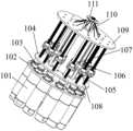
- Fig. 5is a perspective view of the structure of the driving mechanism in the flexible mechanical arm based on the cross-axis hinge provided by the present invention.
- the cross-axis articulated flexible robot armprovided by the present invention includes a drive mechanism 1 and an arm segment mechanism 2;
- the arm segment mechanism 2includes first joint units that are identical in structure and arranged in sequence I.
- Each joint unitincludes a plurality of joint links 21, a plurality of cross joint shafts 22, an elastic support rod 23 and three driving ropes 24; There are two symmetrical U-shaped grooves 215 formed in the inward depression, a first central hole 213 is formed through the axis, and a connecting groove 212 is formed in the radially symmetrical depression in the middle of both end faces, which is located on both sides of the connecting groove 212.
- a plurality of guide holes 214are formed through axial penetration; a cross joint shaft 22 is provided between two adjacent joint links 21, and the cross joint shaft 22 is composed of two joint shafts 221, and a second center is formed through the middle part.
- Holes 222, the outer parts of the two joint shafts 221are respectively embedded in the connecting grooves 212 on the adjacent end surfaces of two adjacent joint connecting rods 21, thereby forming the first rotating pair 26; and the second central hole 222 is connected with the first
- the central holes 213are aligned; the elastic support rod 23 runs through the first central hole 213 arranged on each joint link 21 and the second central hole 222 on the cross joint shaft 22; three driving ropes 24 are arranged at intervals, and one end is connected to the On the joint link 21 at the end of the joint unit, the middle part is connected to the drive mechanism 1 after passing through the guide hole 214 at the same position as the joint link 21 on the joint unit and all joint units on the front side;
- the drive mechanism 1includes four drive units respectively connected to a joint unit, a first connecting plate 102, a second connecting plate 104, a third connecting plate 109, a plurality of first connecting rods 110 and a fourth connecting plate 111 ;
- the first connection plate 102, the second connection plate 104 and the third connection plate 109are arranged at intervals in a parallel manner and are connected to each other;
- each drive unitcomprises three motors 101, three shaft couplings 103, three leading screws 105, three slide blocks 108, three guide rods 106 and three rope connectors 107; wherein, the distance between the three motors 101 Installed on the bottom surface of the first connecting plate 102, the output end runs through the first connecting plate 102;
- the coupling 103is located between the first connecting plate 102 and the second connecting plate 104; one end of the lead screw 105 is installed in a rotating manner
- On the third connection plate 109, the other endpasses through the second connection plate 104 and is connected with the output end of a motor
- connection groove 212 on the end surface of the joint link 21are inclined surfaces 211 , so that the adjacent joint links 21 have a certain rotation space.
- the outer portion of the joint shaft 221is an arc-shaped surface, and the connecting groove 212 on the joint connecting rod 21 is an arc-shaped groove.
- the front end surface of the joint link 21 located at the head end on the first joint unit I and the rear end surface of the joint link 21 located at the end on the fourth joint unit IVare arranged in a planar structure.
- each motor 101 on the drive mechanism 1can be used to make Drive the rope 24 to move, thereby driving each joint unit to realize the bending motion of two degrees of freedom, and finally realize the control of the end position of the flexible manipulator;
- the flexible manipulatorhas the characteristics of flexible movement, high compliance, high torsional rigidity, With the advantages of compact structure and small outer diameter, it can be well adapted to various detection and operation tasks in narrow spaces.
Landscapes
- Engineering & Computer Science (AREA)
- Robotics (AREA)
- Mechanical Engineering (AREA)
- Manipulator (AREA)
Abstract
Description
Translated fromChinese本发明属于机器人技术领域,特别是涉及一种基于十字轴铰接的柔性机械臂。The invention belongs to the technical field of robots, in particular to a flexible mechanical arm articulated based on a cross axis.
传统刚性关节的机械臂操作空间大,但结构笨重,运动灵活性差,因而在狭窄空间环境下的应用受限,例如管道检测、复杂箱体内的检测、加工等。因此,作为一种特种机器人,柔性机械臂具有自由度多、动作灵活等优点成为了必然选择。Traditional rigid-joint manipulators have a large operating space, but their structures are bulky and their movement flexibility is poor. Therefore, their applications in narrow space environments are limited, such as pipeline inspections, inspections in complex boxes, and processing. Therefore, as a special robot, the flexible manipulator has the advantages of many degrees of freedom and flexible movements, which has become an inevitable choice.
柔性机械臂为了实现高的运动柔性,关节通常采用十字万向铰链或球铰结构。传统的万向铰链结构复杂,导致柔性机械臂外径尺寸较大,从而限制其应用;采用球铰结构的柔性机械臂普遍存在抗扭转刚度低的问题。此外,还有一些柔性臂采用纯柔性材料支撑作为关节,运动柔性得到提升,但是存在刚度低、轴向压缩等问题。In order to achieve high motion flexibility of flexible manipulators, the joints usually adopt cross universal hinge or ball joint structure. The complex structure of the traditional universal joint leads to a large outer diameter of the flexible manipulator, which limits its application; the flexible manipulator with the ball joint structure generally has the problem of low torsional stiffness. In addition, some flexible arms are supported by purely flexible materials as joints, which improve the flexibility of movement, but there are problems such as low stiffness and axial compression.
发明内容Contents of the invention
为了解决上述问题,本发明的目的在于提供一种基于十字轴铰接的柔性机械臂。In order to solve the above problems, the object of the present invention is to provide a flexible mechanical arm articulated based on a cross axis.
为了达到上述目的,本发明提供的基于十字轴铰接的柔性机械臂包括驱动机构和臂段机构;所述臂段机构包括结构完全相同且依次排布的第一关节单元、第二关节单元、第三关节单元和第四关节单元;其中第一关节单元的首端连接在驱动机构上;In order to achieve the above object, the flexible mechanical arm articulated based on the cross axis provided by the present invention includes a drive mechanism and an arm section mechanism; the arm section mechanism includes a first joint unit, a second joint unit, a second joint unit, and Three joint units and a fourth joint unit; wherein the head end of the first joint unit is connected to the driving mechanism;
每个关节单元包括多个关节连杆、多个十字关节轴、一根弹性支撑杆与三 条驱动绳索;其中:所述关节连杆的整体为圆柱体形结构,中部圆周面上向内凹陷形成有两个对称的U型槽,轴心处贯通形成有一个第一中心孔,两端面中部沿径向对称凹陷形成有一个连接槽,位于连接槽两侧的部位沿轴向贯通形成有多个导向孔;相邻两个关节连杆之间设有一个十字关节轴,十字关节轴由两根关节轴构成,中部贯通形成有一个第二中心孔,两根关节轴的外侧部位分别嵌入在相邻两个关节连杆上相邻端面的连接槽内,由此形成第一转动副;并且第二中心孔与第一中心孔对齐;弹性支撑杆贯穿设置在各关节连杆上的第一中心孔和十字关节轴上的第二中心孔内;三条驱动绳索间隔设置,一端连接在位于本关节单元末端的关节连杆上,中部穿过位于本关节单元及前侧的所有关节单元上关节连杆同一位置的导向孔后连接在驱动机构上;Each joint unit includes multiple joint connecting rods, multiple cross joint shafts, an elastic support rod and three driving ropes; wherein: the joint connecting rod is in the shape of a cylinder as a whole, and the middle peripheral surface is concaved inward to form a Two symmetrical U-shaped grooves, a first central hole is formed through the center of the axis, a connecting groove is formed in the radially symmetrical depression in the middle of both ends, and a plurality of guides are formed in the parts on both sides of the connecting groove along the axial direction. hole; a cross joint shaft is provided between two adjacent joint rods, the cross joint shaft is composed of two joint shafts, a second center hole is formed through the middle part, and the outer parts of the two joint shafts are respectively embedded in the adjacent In the connecting grooves on the adjacent end surfaces of the two joint links, the first rotating pair is formed; and the second center hole is aligned with the first center hole; the elastic support rod passes through the first center hole provided on each joint link and the second center hole on the cross joint shaft; three driving ropes are arranged at intervals, one end is connected to the joint link at the end of the joint unit, and the middle part passes through the joint links on the joint unit and all joint units on the front side The guide hole at the same position is then connected to the drive mechanism;
所述驱动机构包括四个分别与一个关节单元相连接的驱动单元、第一连接盘、第二连接盘、第三连接盘、多根第一连杆和第四连接盘;其中,第一连接盘、第二连接盘和第三连接盘以平行的方式间隔设置且相互连接;第四连接盘利用多根第一连杆与第三连接盘固定连接;每个驱动单元包括三台电机、三个联轴器、三根丝杠、三个滑块、三根导向杆和三个绳索连接部;其中,三台电机间隔距离安装在第一连接盘的底面上,输出端贯穿第一连接盘;联轴器位于第一连接盘和第二连接盘之间;丝杠的一端以转动的方式安装在第三连接盘上,另一端贯穿第二连接盘后通过一个联轴器与一台电机的输出端相连接;每根丝杠的附近安装一根导向杆,导向杆的两端分别固定在第二连接盘和第三连接盘上;每个滑块同时套装在一根丝杠和一根导向杆上,因此能够沿导向杆往复移动,并且滑块上安装有一个绳索连接部;臂段机构上每根驱动绳索的另一端贯穿第四连接盘、第三连接盘后连接在一个绳索连接部上;第四连接盘的顶面与 第一关节单元上位于首端的关节连杆前端面相连接。The drive mechanism includes four drive units respectively connected to a joint unit, a first connection plate, a second connection plate, a third connection plate, a plurality of first connecting rods and a fourth connection plate; wherein, the first connection The disk, the second connection disk and the third connection disk are arranged at intervals in a parallel manner and are connected to each other; the fourth connection disk is fixedly connected to the third connection disk by a plurality of first connecting rods; each drive unit includes three motors, three a shaft coupling, three lead screws, three sliders, three guide rods and three rope connection parts; wherein, three motors are installed on the bottom surface of the first connection plate at intervals, and the output end runs through the first connection plate; The shaft device is located between the first connecting plate and the second connecting plate; one end of the lead screw is installed on the third connecting plate in a rotating manner, and the other end passes through the second connecting plate and passes through a coupling and the output of a motor. The ends are connected; a guide rod is installed near each screw, and the two ends of the guide rod are respectively fixed on the second connection plate and the third connection plate; each slider is set on a lead screw and a guide at the same time. Therefore, it can move back and forth along the guide rod, and a rope connection part is installed on the slider; the other end of each driving rope on the arm section mechanism passes through the fourth connection plate and the third connection plate and is connected to a rope connection part Above; the top surface of the fourth connection plate is connected with the front end surface of the joint link at the head end of the first joint unit.
所述关节连杆的端面上位于连接槽两侧的部位为倾斜面,这样可使相邻关节连杆具有一定的转动空间。The parts on both sides of the connecting groove on the end surface of the joint connecting rod are inclined surfaces, so that the adjacent joint connecting rods have a certain rotation space.
所述关节轴的外侧部位为弧形面,同时关节连杆上的连接槽为弧形槽。The outer part of the joint shaft is an arc-shaped surface, and the connecting groove on the joint connecting rod is an arc-shaped groove.
所述第一关节单元上位于首端的关节连杆前端面和第四关节单元上位于末端的关节连杆后端面设置成平面结构。The front end surface of the joint link located at the head end on the first joint unit and the rear end surface of the joint link located at the end of the fourth joint unit are arranged in a planar structure.
本发明提供的基于十字轴铰接的柔性机械臂具有以下优点:The cross-axis articulated flexible mechanical arm provided by the present invention has the following advantages:
1、采用十字关节轴实现各个关节连杆之间的连接,使得该柔性机械臂外径尺寸较小,同时增加了柔性机械臂的抗扭转刚度,提高了柔性机械臂的可控性,可以很好地适应各种狭窄空间的检测和操作任务。1. The cross joint shaft is used to realize the connection between each joint link, which makes the outer diameter of the flexible manipulator smaller, and at the same time increases the torsional stiffness of the flexible manipulator, improves the controllability of the flexible manipulator, and can be easily Well adapted to various detection and manipulation tasks in narrow spaces.
2、关节连杆采用刚性材料,提高了柔性机械臂的刚度和轴向不可压缩性,同时端面设置倾斜面,保证了柔性机械臂的工作空间和运动灵活性。2. The joint connecting rod is made of rigid material, which improves the stiffness and axial incompressibility of the flexible manipulator. At the same time, an inclined surface is set on the end face to ensure the working space and movement flexibility of the flexible manipulator.
图1为本发明提供的基于十字轴铰接的柔性机械臂结构立体图。Fig. 1 is a perspective view of the structure of the flexible robot arm based on the cross-axis hinge provided by the present invention.
图2为本发明提供的基于十字轴铰接的柔性机械臂中臂段机构的一个关节单元结构立体图。Fig. 2 is a structural perspective view of a joint unit of the middle arm segment mechanism of the flexible mechanical arm based on cross-axis articulation provided by the present invention.
图3为本发明提供的基于十字轴铰接的柔性机械臂中关节连杆结构立体图。Fig. 3 is a perspective view of the structure of the joint link in the flexible mechanical arm based on the cross-axis hinge provided by the present invention.
图4为本发明提供的基于十字轴铰接的柔性机械臂中十字关节轴结构立体图。Fig. 4 is a perspective view of the structure of the cross joint shaft in the flexible mechanical arm based on cross shaft articulation provided by the present invention.
图5为本发明提供的基于十字轴铰接的柔性机械臂中驱动机构结构立体图。Fig. 5 is a perspective view of the structure of the driving mechanism in the flexible mechanical arm based on the cross-axis hinge provided by the present invention.
下面结合附图对本发明提供的基于十字轴铰接的柔性机械臂进行详细说 明。The cross-axis articulated flexible mechanical arm provided by the present invention will be described in detail below in conjunction with the accompanying drawings.
如图1—图5所示,本发明提供的基于十字轴铰接的柔性机械臂包括驱动机构1和臂段机构2;所述臂段机构2包括结构完全相同且依次排布的第一关节单元Ⅰ、第二关节单元Ⅱ、第三关节单元Ⅲ和第四关节单元Ⅳ;其中第一关节单元Ⅰ的首端连接在驱动机构1上;As shown in Figures 1 to 5, the cross-axis articulated flexible robot arm provided by the present invention includes a
每个关节单元包括多个关节连杆21、多个十字关节轴22、一根弹性支撑杆23与三条驱动绳索24;其中:所述关节连杆21的整体为圆柱体形结构,中部圆周面上向内凹陷形成有两个对称的U型槽215,轴心处贯通形成有一个第一中心孔213,两端面中部沿径向对称凹陷形成有一个连接槽212,位于连接槽212两侧的部位沿轴向贯通形成有多个导向孔214;相邻两个关节连杆21之间设有一个十字关节轴22,十字关节轴22由两根关节轴221构成,中部贯通形成有一个第二中心孔222,两根关节轴221的外侧部位分别嵌入在相邻两个关节连杆21上相邻端面的连接槽212内,由此形成第一转动副26;并且第二中心孔222与第一中心孔213对齐;弹性支撑杆23贯穿设置在各关节连杆21上的第一中心孔213和十字关节轴22上的第二中心孔222内;三条驱动绳索24间隔设置,一端连接在位于本关节单元末端的关节连杆21上,中部穿过位于本关节单元及前侧的所有关节单元上关节连杆21同一位置的导向孔214后连接在驱动机构1上;Each joint unit includes a plurality of
所述驱动机构1包括四个分别与一个关节单元相连接的驱动单元、第一连接盘102、第二连接盘104、第三连接盘109、多根第一连杆110和第四连接盘111;其中,第一连接盘102、第二连接盘104和第三连接盘109以平行的方式间隔设置且相互连接;第四连接盘111利用多根第一连杆110与第三连接盘109 固定连接;每个驱动单元包括三台电机101、三个联轴器103、三根丝杠105、三个滑块108、三根导向杆106和三个绳索连接部107;其中,三台电机101间隔距离安装在第一连接盘102的底面上,输出端贯穿第一连接盘102;联轴器103位于第一连接盘102和第二连接盘104之间;丝杠105的一端以转动的方式安装在第三连接盘109上,另一端贯穿第二连接盘104后通过一个联轴器103与一台电机101的输出端相连接;每根丝杠105的附近安装一根导向杆106,导向杆106的两端分别固定在第二连接盘104和第三连接盘109上;每个滑块108同时套装在一根丝杠105和一根导向杆106上,因此能够沿导向杆106往复移动,并且滑块108上安装有一个绳索连接部107;臂段机构2上每根驱动绳索24的另一端贯穿第四连接盘111、第三连接盘109后连接在一个绳索连接部107上;第四连接盘111的顶面与第一关节单元Ⅰ上位于首端的关节连杆21前端面相连接。The
所述关节连杆21的端面上位于连接槽212两侧的部位为倾斜面211,这样可使相邻关节连杆21具有一定的转动空间。The parts on both sides of the
所述关节轴221的外侧部位为弧形面,同时关节连杆21上的连接槽212为弧形槽。The outer portion of the
所述第一关节单元Ⅰ上位于首端的关节连杆21前端面和第四关节单元Ⅳ上位于末端的关节连杆21后端面设置成平面结构。The front end surface of the
本发明提供的基于十字轴铰接的柔性机械臂的工作原理为:可利用驱动机构1上的每台电机101分别通过相应的联轴器103、丝杠105、滑块108、绳索连接部107使驱动绳索24移动,由此带动每个关节单元实现两个自由度的弯曲运动,最终实现对该柔性机械臂末端位置的控制;该柔性机械臂具有运动灵活、 柔顺性高、抗扭转刚度大、结构紧凑、外径尺寸小等优点,可以很好地适应各种狭窄空间的检测和操作任务。The working principle of the flexible mechanical arm based on the cross shaft hinge provided by the present invention is: each
Claims (4)
Translated fromChineseApplications Claiming Priority (2)
| Application Number | Priority Date | Filing Date | Title |
|---|---|---|---|
| CN202111216614.XACN113733154B (en) | 2021-10-19 | 2021-10-19 | Flexible mechanical arm based on cross shaft hinge |
| CN202111216614.X | 2021-10-19 |
Publications (1)
| Publication Number | Publication Date |
|---|---|
| WO2023065658A1true WO2023065658A1 (en) | 2023-04-27 |
Family
ID=78726889
Family Applications (1)
| Application Number | Title | Priority Date | Filing Date |
|---|---|---|---|
| PCT/CN2022/094128CeasedWO2023065658A1 (en) | 2021-10-19 | 2022-05-20 | Flexible mechanical arm based on universal-joint hinge |
Country Status (2)
| Country | Link |
|---|---|
| CN (1) | CN113733154B (en) |
| WO (1) | WO2023065658A1 (en) |
Cited By (5)
| Publication number | Priority date | Publication date | Assignee | Title |
|---|---|---|---|---|
| CN116834060A (en)* | 2023-08-25 | 2023-10-03 | 烟台大学 | Pneumatic rigidity-variable joint |
| CN117001710A (en)* | 2023-07-10 | 2023-11-07 | 浙江大学 | A large-angle, variable-stiffness flexible joint |
| CN118456493A (en)* | 2024-06-13 | 2024-08-09 | 江苏智慧工场技术研究院有限公司 | Bionic mechanical arm and bionic mechanical arm system |
| CN118456376A (en)* | 2024-07-12 | 2024-08-09 | 西南科技大学 | A rigid-flexible collaborative vehicle-mounted super-redundant robot |
| CN119772860A (en)* | 2025-02-21 | 2025-04-08 | 合肥工业大学 | A parallel robot platform based on flexible cable and continuum composite drive |
Families Citing this family (1)
| Publication number | Priority date | Publication date | Assignee | Title |
|---|---|---|---|---|
| CN113733154B (en)* | 2021-10-19 | 2023-09-26 | 中国民航大学 | Flexible mechanical arm based on cross shaft hinge |
Citations (8)
| Publication number | Priority date | Publication date | Assignee | Title |
|---|---|---|---|---|
| CN104552286A (en)* | 2014-12-26 | 2015-04-29 | 上海大学 | Continuous multi-joint mechanical arm device |
| US20150122071A1 (en)* | 2013-11-05 | 2015-05-07 | Samsung Electronics Co., Ltd. | Actuator and manipulator including the same |
| CN105150241A (en)* | 2015-09-28 | 2015-12-16 | 哈尔滨工业大学深圳研究生院 | Two-degree-of-freedom mechanical arm joint driven by ropes |
| CN106163421A (en)* | 2014-02-21 | 2016-11-23 | 直观外科手术操作公司 | Articulateable member with constrained motion and related apparatus and methods |
| CN106737628A (en)* | 2017-02-14 | 2017-05-31 | 深圳源创智能机器人有限公司 | A kind of flexible charging robot driven based on rope |
| CN111482954A (en)* | 2020-04-09 | 2020-08-04 | 北京精密机电控制设备研究所 | Universal joint for mechanical arm and continuous mechanical arm |
| CN112356016A (en)* | 2020-11-23 | 2021-02-12 | 长沙理工大学 | Wire drive link capable of realizing bending motion decoupling |
| CN113733154A (en)* | 2021-10-19 | 2021-12-03 | 中国民航大学 | Flexible mechanical arm based on cross shaft hinge joint |
Family Cites Families (5)
| Publication number | Priority date | Publication date | Assignee | Title |
|---|---|---|---|---|
| KR101173619B1 (en)* | 2010-04-29 | 2012-08-13 | 한국과학기술원 | Robot apparatus for endoscopic surgery |
| CN206200964U (en)* | 2016-11-10 | 2017-05-31 | 燕山大学 | The flexible mechanical arm of Coupled Rigid-flexible |
| CN206393667U (en)* | 2016-12-08 | 2017-08-11 | 燕山大学 | The radial flexible mechanical arm driven based on rope |
| CN107322584B (en)* | 2017-08-30 | 2020-01-10 | 享奕自动化科技(上海)有限公司 | Snake-shaped arm |
| CN109940597A (en)* | 2019-04-19 | 2019-06-28 | 中国民航大学 | A continuous robotic arm imitating snake vertebrae |
- 2021
- 2021-10-19CNCN202111216614.XApatent/CN113733154B/enactiveActive
- 2022
- 2022-05-20WOPCT/CN2022/094128patent/WO2023065658A1/ennot_activeCeased
Patent Citations (8)
| Publication number | Priority date | Publication date | Assignee | Title |
|---|---|---|---|---|
| US20150122071A1 (en)* | 2013-11-05 | 2015-05-07 | Samsung Electronics Co., Ltd. | Actuator and manipulator including the same |
| CN106163421A (en)* | 2014-02-21 | 2016-11-23 | 直观外科手术操作公司 | Articulateable member with constrained motion and related apparatus and methods |
| CN104552286A (en)* | 2014-12-26 | 2015-04-29 | 上海大学 | Continuous multi-joint mechanical arm device |
| CN105150241A (en)* | 2015-09-28 | 2015-12-16 | 哈尔滨工业大学深圳研究生院 | Two-degree-of-freedom mechanical arm joint driven by ropes |
| CN106737628A (en)* | 2017-02-14 | 2017-05-31 | 深圳源创智能机器人有限公司 | A kind of flexible charging robot driven based on rope |
| CN111482954A (en)* | 2020-04-09 | 2020-08-04 | 北京精密机电控制设备研究所 | Universal joint for mechanical arm and continuous mechanical arm |
| CN112356016A (en)* | 2020-11-23 | 2021-02-12 | 长沙理工大学 | Wire drive link capable of realizing bending motion decoupling |
| CN113733154A (en)* | 2021-10-19 | 2021-12-03 | 中国民航大学 | Flexible mechanical arm based on cross shaft hinge joint |
Cited By (5)
| Publication number | Priority date | Publication date | Assignee | Title |
|---|---|---|---|---|
| CN117001710A (en)* | 2023-07-10 | 2023-11-07 | 浙江大学 | A large-angle, variable-stiffness flexible joint |
| CN116834060A (en)* | 2023-08-25 | 2023-10-03 | 烟台大学 | Pneumatic rigidity-variable joint |
| CN118456493A (en)* | 2024-06-13 | 2024-08-09 | 江苏智慧工场技术研究院有限公司 | Bionic mechanical arm and bionic mechanical arm system |
| CN118456376A (en)* | 2024-07-12 | 2024-08-09 | 西南科技大学 | A rigid-flexible collaborative vehicle-mounted super-redundant robot |
| CN119772860A (en)* | 2025-02-21 | 2025-04-08 | 合肥工业大学 | A parallel robot platform based on flexible cable and continuum composite drive |
Also Published As
| Publication number | Publication date |
|---|---|
| CN113733154A (en) | 2021-12-03 |
| CN113733154B (en) | 2023-09-26 |
Similar Documents
| Publication | Publication Date | Title |
|---|---|---|
| CN113733153B (en) | A seven-degree-of-freedom flexible manipulator based on offset cross-axis articulation | |
| WO2023065658A1 (en) | Flexible mechanical arm based on universal-joint hinge | |
| US10737379B2 (en) | Compact parallel kinematics robot | |
| CN102528794B (en) | Parallel robot and wrist module | |
| CN110900592B (en) | A Reconfigurable Redundant Manipulator Based on Rope Drive | |
| JPS6116599B2 (en) | ||
| CN105904441B (en) | The movement of one kind two two rotates four-degree-of-freedom holohedral symmetry parallel institution | |
| CN109955281A (en) | Two-degree-of-freedom large-angle flexible robot joints and robots based on rope drive | |
| CN105834576A (en) | Redundant-driven friction stir welding parallel robot | |
| CN110815182B (en) | Five-degree-of-freedom parallel mechanism containing dual-drive composite branched chains | |
| CN118322248B (en) | Three-degree-of-freedom robot joint and manipulator | |
| CN109955284A (en) | Two-transfer, one-shift, three-degree-of-freedom force feedback device | |
| CN110238874A (en) | A robotic arm for contact scanning imaging of objects of interest through narrow lumens | |
| CN205702834U (en) | A kind of agitating friction weldering parallel robot of redundant drive | |
| CN112008699B (en) | A completely decoupled two-rotation and one-movement parallel mechanism | |
| CN112008697A (en) | Two-rotation one-movement three-freedom-degree decoupling parallel mechanism | |
| CN102357881A (en) | Three-dimensional translation and one-dimensional rotation parallel mechanism containing 5R closed-loop sub-chains | |
| CN111195903B (en) | Underactuated Universal Flexible Arm and Robot | |
| CN102294693A (en) | Double-freedom degree rotation parallel mechanism | |
| CN110355741B (en) | Parallel mechanism with two motion modes 3T1R and 2T2R | |
| CN110270982B (en) | A parallel mechanism mixer | |
| CN113799167B (en) | Three-degree-of-freedom composite flexible bionic ball socket joint | |
| CN111975749A (en) | High-speed parallel robot with decoupling of rotation and movement degrees of freedom | |
| WO2011155070A1 (en) | Parallel manipulator | |
| CN110465923A (en) | There are three mobile, a two mobile rotations and two one Move Modes of rotation parallel institutions |
Legal Events
| Date | Code | Title | Description |
|---|---|---|---|
| 121 | Ep: the epo has been informed by wipo that ep was designated in this application | Ref document number:22882283 Country of ref document:EP Kind code of ref document:A1 | |
| NENP | Non-entry into the national phase | Ref country code:DE | |
| 122 | Ep: pct application non-entry in european phase | Ref document number:22882283 Country of ref document:EP Kind code of ref document:A1 |