WO2023063323A1 - Communication method, user equipment, and base station - Google Patents
Communication method, user equipment, and base stationDownload PDFInfo
- Publication number
- WO2023063323A1 WO2023063323A1PCT/JP2022/037903JP2022037903WWO2023063323A1WO 2023063323 A1WO2023063323 A1WO 2023063323A1JP 2022037903 WJP2022037903 WJP 2022037903WWO 2023063323 A1WO2023063323 A1WO 2023063323A1
- Authority
- WO
- WIPO (PCT)
- Prior art keywords
- pdcp
- mbs
- data
- base station
- hfn
- Prior art date
- Legal status (The legal status is an assumption and is not a legal conclusion. Google has not performed a legal analysis and makes no representation as to the accuracy of the status listed.)
- Ceased
Links
Images


Classifications
- H—ELECTRICITY
- H04—ELECTRIC COMMUNICATION TECHNIQUE
- H04W—WIRELESS COMMUNICATION NETWORKS
- H04W76/00—Connection management
- H04W76/20—Manipulation of established connections
- H04W76/27—Transitions between radio resource control [RRC] states
- H—ELECTRICITY
- H04—ELECTRIC COMMUNICATION TECHNIQUE
- H04W—WIRELESS COMMUNICATION NETWORKS
- H04W4/00—Services specially adapted for wireless communication networks; Facilities therefor
- H04W4/06—Selective distribution of broadcast services, e.g. multimedia broadcast multicast service [MBMS]; Services to user groups; One-way selective calling services
- H—ELECTRICITY
- H04—ELECTRIC COMMUNICATION TECHNIQUE
- H04W—WIRELESS COMMUNICATION NETWORKS
- H04W72/00—Local resource management
- H04W72/30—Resource management for broadcast services
- H—ELECTRICITY
- H04—ELECTRIC COMMUNICATION TECHNIQUE
- H04W—WIRELESS COMMUNICATION NETWORKS
- H04W76/00—Connection management
- H04W76/10—Connection setup
- H04W76/11—Allocation or use of connection identifiers
- H—ELECTRICITY
- H04—ELECTRIC COMMUNICATION TECHNIQUE
- H04W—WIRELESS COMMUNICATION NETWORKS
- H04W76/00—Connection management
- H04W76/40—Connection management for selective distribution or broadcast
Definitions
- the present disclosurerelates to communication methods, user equipment, and base stations used in mobile communication systems.
- NRNew Radio
- 5Gfifth generation
- 4Gfourth generation
- MBSmulticast broadcast services
- 5G/NR multicast broadcast serviceswill provide improved services over 4G/LTE multicast broadcast services.
- an object of the present disclosureis to provide a communication method, a user equipment, and a base station that enable improved multicast broadcast services.
- a communication methodis a communication method executed by a user device that receives a series of PDCP (Packet Data Convergence Protocol) data PDUs (Protocol Data Units) constituting multicast/broadcast service (MBS) data from a base station. and receiving, from the base station, a radio resource control (RRC) Reconfiguration message containing a hyperframe number that is incremented each time the sequence number contained in the PDCP data PDU transmitted by the base station is incremented. and determining initial values of PDCP state variables managed by the user equipment based on the hyperframe number included in the RRC Reconfiguration message.
- PDCPPacket Data Convergence Protocol
- PDUsProtocol Data Units
- MBSmulticast/broadcast service
- a user deviceis a user device that receives a series of PDCP (Packet Data Convergence Protocol) data PDUs (Protocol Data Units) constituting multicast broadcast service (MBS) data from a base station, A receiving unit that receives from the base station a radio resource control (RRC) Reconfiguration message containing a hyperframe number that is counted up each time the sequence number included in the PDCP data PDU sent by the base station goes around, and the RRC Reconfiguration a control unit that determines initial values of PDCP state variables managed by the user equipment based on the hyperframe number included in the message.
- PDCPPacket Data Convergence Protocol
- MMSmulticast broadcast service
- a base stationis a base station that transmits a series of PDCP (Packet Data Convergence Protocol) data PDU (Protocol Data Unit) constituting multicast broadcast service (MBS) data to a user device, It comprises a transmission unit that transmits a radio resource control (RRC) Reconfiguration message containing a hyperframe number that is counted up each time the sequence number contained in the PDCP data PDU transmitted by the base station goes around, to the user equipment.
- PDCPPacket Data Convergence Protocol
- PDUProtocol Data Unit
- MMSmulticast broadcast service
- FIG. 1is a diagram showing the configuration of a mobile communication system according to an embodiment
- FIG.It is a figure which shows the structure of UE (user apparatus) which concerns on embodiment.
- Itis a diagram showing the configuration of a gNB (base station) according to the embodiment.
- FIG. 2is a diagram showing the configuration of a protocol stack of a user plane radio interface that handles data
- FIG. 2is a diagram showing the configuration of a protocol stack of a radio interface of a control plane that handles signaling (control signals)
- FIG. 4is a diagram illustrating an overview of MBS traffic distribution according to an embodiment
- FIG. 4is a diagram showing an example of internal processing regarding MBS reception of the UE 100 according to the embodiment;
- FIG. 4is a diagram showing another example of internal processing regarding MBS reception of the UE 100 according to the embodiment;
- FIG. 4is a diagram showing the operation of the PDCP layer in the mobile communication system according to the embodiment;
- FIG. 4is a diagram illustrating an example of PDCP state variables according to an embodiment; It is a figure which shows an example of PDCP data PDU which comprises the MBS data which concerns on embodiment.
- FIG. 4illustrates an operation of determining RCVD_COUNT, which is a COUNT value of received PDCP data PDUs, at a receiving PDCP entity of a UE according to an embodiment;
- FIG. 4illustrates an example of operation of a receiving PDCP entity in a UE according to an embodiment;
- FIG. 4is a diagram illustrating operation of a UE according to an embodiment; It is a figure which shows the operation
- FIG. 10is a diagram showing PDCP data PDUs according to the third embodiment; It is a figure which shows the operation
- FIG. 1is a diagram showing the configuration of a mobile communication system according to an embodiment.
- the mobile communication system 1complies with the 3GPP standard 5th generation system (5GS: 5th Generation System).
- 5GSwill be described below as an example, an LTE (Long Term Evolution) system may be at least partially applied to the mobile communication system.
- 6Gsixth generation
- the mobile communication system 1includes a user equipment (UE: User Equipment) 100, a 5G radio access network (NG-RAN: Next Generation Radio Access Network) 10, and a 5G core network (5GC: 5G Core Network) 20.
- UEUser Equipment
- NG-RANNext Generation Radio Access Network
- 5GC5G Core Network
- the NG-RAN 10may be simply referred to as the RAN 10 below.
- the 5GC 20is sometimes simply referred to as a core network (CN) 20 .
- CNcore network
- the UE 100is a mobile wireless communication device.
- the UE 100may be any device as long as it is used by a user.
- the UE 100may be a mobile phone terminal (including a smartphone) or a tablet terminal, a notebook PC, a communication module (including a communication card or chipset), a sensor or a device provided in a sensor, a vehicle or a device provided in the vehicle (Vehicle UE ), an aircraft or a device (Aerial UE) provided on the aircraft.
- the NG-RAN 10includes a base station (called “gNB” in the 5G system) 200.
- the gNBs 200are interconnected via an Xn interface, which is an interface between base stations.
- the gNB 200manages one or more cells.
- the gNB 200performs radio communication with the UE 100 that has established connection with its own cell.
- the gNB 200has a radio resource management (RRM) function, a user data (hereinafter simply referred to as “data”) routing function, a measurement control function for mobility control/scheduling, and the like.
- RRMradio resource management
- a “cell”is used as a term indicating the minimum unit of a wireless communication area.
- a “cell”is also used as a term indicating a function or resource for radio communication with the UE 100 .
- One cellbelongs to one carrier frequency (hereinafter simply called "frequency").
- the gNBcan also be connected to the EPC (Evolved Packet Core), which is the LTE core network.
- EPCEvolved Packet Core
- LTE base stationscan also connect to 5GC.
- An LTE base station and a gNBmay also be connected via an inter-base station interface.
- 5GC20includes AMF (Access and Mobility Management Function) and UPF (User Plane Function) 300.
- AMFperforms various mobility control etc. with respect to UE100.
- AMFmanages the mobility of UE 100 by communicating with UE 100 using NAS (Non-Access Stratum) signaling.
- the UPFcontrols data transfer.
- AMF and UPFare connected to gNB 200 via NG interface, which is a base station-core network interface.
- FIG. 2is a diagram showing the configuration of the UE 100 (user equipment) according to the embodiment.
- UE 100includes a receiver 110 , a transmitter 120 and a controller 130 .
- the receiving unit 110 and the transmitting unit 120constitute a wireless communication unit that performs wireless communication with the gNB 200 .
- the receiving unit 110performs various types of reception under the control of the control unit 130.
- the receiver 110includes an antenna and a receiver.
- the receiverconverts a radio signal received by the antenna into a baseband signal (received signal) and outputs the baseband signal (received signal) to control section 130 .
- the transmission unit 120performs various transmissions under the control of the control unit 130.
- the transmitter 120includes an antenna and a transmitter.
- the transmitterconverts a baseband signal (transmission signal) output from the control unit 130 into a radio signal and transmits the radio signal from an antenna.
- Control unit 130performs various controls and processes in the UE 100. Such processing includes processing of each layer, which will be described later.
- Control unit 130includes at least one processor and at least one memory.
- the memorystores programs executed by the processor and information used for processing by the processor.
- the processormay include a baseband processor and a CPU (Central Processing Unit).
- the baseband processormodulates/demodulates and encodes/decodes the baseband signal.
- the CPUexecutes programs stored in the memory to perform various processes.
- FIG. 3is a diagram showing the configuration of gNB 200 (base station) according to the embodiment.
- the gNB 200comprises a transmitter 210 , a receiver 220 , a controller 230 and a backhaul communicator 240 .
- the transmitting unit 210 and the receiving unit 220constitute a radio communication unit that performs radio communication with the UE 100 .
- the backhaul communication unit 240constitutes a network communication unit that communicates with the CN 20 .
- the transmission unit 210performs various transmissions under the control of the control unit 230.
- Transmitter 210includes an antenna and a transmitter.
- the transmitterconverts a baseband signal (transmission signal) output by the control unit 230 into a radio signal and transmits the radio signal from an antenna.
- the receiving unit 220performs various types of reception under the control of the control unit 230.
- the receiver 220includes an antenna and a receiver.
- the receiverconverts the radio signal received by the antenna into a baseband signal (received signal) and outputs the baseband signal (received signal) to the control unit 230 .
- Control unit 230performs various controls and processes in the gNB200. Such processing includes processing of each layer, which will be described later.
- Control unit 230includes at least one processor and at least one memory.
- the memorystores programs executed by the processor and information used for processing by the processor.
- the processormay include a baseband processor and a CPU.
- the baseband processormodulates/demodulates and encodes/decodes the baseband signal.
- the CPUexecutes programs stored in the memory to perform various processes.
- the backhaul communication unit 240is connected to adjacent base stations via the Xn interface, which is an interface between base stations.
- the backhaul communication unit 240is connected to the AMF/UPF 300 via the NG interface, which is the base station-core network interface.
- the gNB 200may be composed of a CU (Central Unit) and a DU (Distributed Unit) (that is, functionally divided), and the two units may be connected by an F1 interface, which is a fronthaul interface.
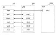
- FIG. 4is a diagram showing the configuration of the protocol stack of the radio interface of the user plane that handles data.
- the user plane radio interface protocolincludes a physical (PHY) layer, a MAC (Medium Access Control) layer, an RLC (Radio Link Control) layer, a PDCP (Packet Data Convergence Protocol) layer, and an SDAP (Service Data Adaptation Protocol) layer. layer.
- PHYphysical
- MACMedium Access Control
- RLCRadio Link Control
- PDCPPacket Data Convergence Protocol
- SDAPService Data Adaptation Protocol
- the PHY layerperforms encoding/decoding, modulation/demodulation, antenna mapping/demapping, and resource mapping/demapping. Data and control information are transmitted between the PHY layer of the UE 100 and the PHY layer of the gNB 200 via physical channels.
- the PHY layer of UE 100receives downlink control information (DCI) transmitted from gNB 200 on a physical downlink control channel (PDCCH). Specifically, the UE 100 blind-decodes the PDCCH using the radio network temporary identifier (RNTI), and acquires the successfully decoded DCI as the DCI addressed to the UE 100 itself.
- the DCI transmitted from the gNB 200is appended with CRC parity bits scrambled by the RNTI.
- the MAC layerperforms data priority control, retransmission processing by hybrid ARQ (HARQ: Hybrid Automatic Repeat reQuest), random access procedures, and the like. Data and control information are transmitted between the MAC layer of the UE 100 and the MAC layer of the gNB 200 via transport channels.
- the MAC layer of gNB 200includes a scheduler. The scheduler determines uplink and downlink transport formats (transport block size, modulation and coding scheme (MCS: Modulation and Coding Scheme)) and resource blocks to be allocated to UE 100 .
- MCSModulation and Coding Scheme
- the RLC layeruses the functions of the MAC layer and PHY layer to transmit data to the RLC layer on the receiving side. Data and control information are transmitted between the RLC layer of the UE 100 and the RLC layer of the gNB 200 via logical channels.
- the PDCP layerperforms header compression/decompression, encryption/decryption, etc.
- the SDAP layermaps IP flows, which are units for QoS (Quality of Service) control by the core network, and radio bearers, which are units for QoS control by AS (Access Stratum). Note that SDAP may not be present when the RAN is connected to the EPC.
- FIG. 5is a diagram showing the protocol stack configuration of the radio interface of the control plane that handles signaling (control signals).
- the radio interface protocol stack of the control planehas an RRC (Radio Resource Control) layer and a NAS (Non-Access Stratum) layer instead of the SDAP layer shown in FIG.
- RRCRadio Resource Control
- NASNon-Access Stratum
- RRC signaling for various settingsis transmitted between the RRC layer of the UE 100 and the RRC layer of the gNB 200.
- the RRC layercontrols logical, transport and physical channels according to establishment, re-establishment and release of radio bearers.
- RRC connectionconnection between the RRC of UE 100 and the RRC of gNB 200
- UE 100is in the RRC connected state.
- RRC connectionno connection between the RRC of UE 100 and the RRC of gNB 200
- UE 100is in the RRC idle state.
- UE 100is in RRC inactive state.
- the NAS layer located above the RRC layerperforms session management and mobility management.
- NAS signalingis transmitted between the NAS layer of UE 100 and the NAS layer of AMF 300A.
- the UE 100has an application layer and the like in addition to the radio interface protocol.
- a layer lower than the NAS layeris called an AS layer.
- MBSis a service that enables data transmission from the NG-RAN 10 to the UE 100 via broadcast or multicast, that is, point-to-multipoint (PTM).
- MBS use casesinclude public safety communications, mission critical communications, V2X (Vehicle to Everything) communications, IPv4 or IPv6 multicast distribution, IPTV (Internet Protocol Television), group communication, and software distribution. .
- a broadcast serviceprovides service to all UEs 100 within a specific service area for applications that do not require highly reliable QoS.
- An MBS session used for broadcast servicesis called a broadcast session.
- a multicast serviceprovides a service not to all UEs 100 but to a group of UEs 100 participating in the multicast service (multicast session).
- An MBS session used for a multicast serviceis called a multicast session.
- a multicast servicecan provide the same content to a group of UEs 100 in a more wirelessly efficient manner than a broadcast service.
- FIG. 6is a diagram showing an overview of MBS traffic distribution according to the embodiment.
- MBS traffic(MBS data) is delivered from a single data source (application service provider) to multiple UEs.
- a 5G CN (5GC) 20which is a 5G core network, receives MBS data from an application service provider, creates a copy of the MBS data (Replication), and distributes it.
- 5GC20From the perspective of 5GC20, two multicast delivery methods are possible: 5GC Shared MBS Traffic delivery and 5GC Individual MBS Traffic delivery.
- the 5GC 20receives single copies of MBS data packets and delivers individual copies of those MBS data packets to individual UEs 100 via per-UE 100 PDU sessions. Therefore, one PDU session per UE 100 needs to be associated with the multicast session.
- the 5GC 20receives a single copy of MBS data packets and delivers the single copy of those MBS packets to the RAN nodes (ie gNB 200).
- a gNB 200receives MBS data packets over an MBS tunnel connection and delivers them to one or more UEs 100 .
- PTPPoint-to-Point
- PTMPoint-to-Multipoint
- the gNB 200delivers individual copies of MBS data packets to individual UEs 100 over the air.
- the gNB 200delivers a single copy of MBS data packets to a group of UEs 100 over the air.
- the gNB 200can dynamically determine which of PTM and PTP to use as the MBS data delivery method for one UE 100 .
- the PTP and PTM delivery methodsare primarily concerned with the user plane. There are two distribution modes, a first distribution mode and a second distribution mode, as MBS data distribution control modes.
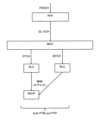
- FIG. 7is a diagram showing distribution modes according to the embodiment.
- the first delivery mode(delivery mode 1: DM1) is a delivery mode that can be used by UE 100 in the RRC connected state, and is a delivery mode for high QoS requirements.
- the first delivery modeis used for multicast sessions among MBS sessions. However, the first delivery mode may be used for broadcast sessions.
- the first delivery modemay also be available for UEs 100 in RRC idle state or RRC inactive state.
- MBS reception settings in the first delivery modeare done by UE-dedicated signaling.
- MBS reception settings in the first distribution modeare performed by an RRC Reconfiguration message (or RRC Release message), which is an RRC message unicast from the gNB 200 to the UE 100 .
- the MBS reception configurationincludes MBS traffic channel configuration information (hereinafter referred to as "MTCH configuration information") regarding the configuration of the MBS traffic channel that transmits MBS data.
- MTCH configuration informationincludes MBS session information (including an MBS session identifier to be described later) regarding the MBS session and scheduling information of the MBS traffic channel corresponding to this MBS session.
- the MBS traffic channel scheduling informationmay include a discontinuous reception (DRX) configuration of the MBS traffic channel.
- DRXdiscontinuous reception
- the discontinuous reception settingincludes a timer value (On Duration Timer) that defines an on duration (On Duration: reception period), a timer value (Inactivity Timer) that extends the on duration, a scheduling interval or DRX cycle (Scheduling Period, DRX Cycle), Scheduling or DRX cycle start subframe offset value (Start Offset, DRX Cycle Offset), ON period timer start delay slot value (Slot Offset), timer value defining maximum time until retransmission (Retransmission Timer), HARQ It may include any one or more parameters of timer value (HARQ RTT Timer) that defines the minimum interval to DL allocation for retransmission.
- HARQ RTT Timertimer value that defines the minimum interval to DL allocation for retransmission.
- the MBS traffic channelis a kind of logical channel and is sometimes called MTCH.
- the MBS traffic channelis mapped to a downlink shared channel (DL-SCH: Down Link-Shared CHannel), which is a type of transport channel.
- DL-SCHDown Link-Shared CHannel
- the second delivery mode(Delivery mode 2: DM2) is a delivery mode that can be used not only by the UE 100 in the RRC connected state but also by the UE 100 in the RRC idle state or RRC inactive state, and is a delivery mode for low QoS requirements. is.
- the second delivery modeis used for broadcast sessions among MBS sessions. However, the second delivery mode may also be applicable to multicast sessions.
- the setting for MBS reception in the second delivery modeis performed by broadcast signaling.
- the configuration of MBS reception in the second delivery modeis done via logical channels broadcasted from the gNB 200 to the UE 100, eg, Broadcast Control Channel (BCCH) and/or Multicast Control Channel (MCCH).
- the UE 100can receive the BCCH and MCCH using, for example, a dedicated RNTI predefined in technical specifications.
- the RNTI for BCCH receptionmay be SI-RNTI
- the RNTI for MCCH receptionmay be MCCH-RNTI.
- the UE 100may receive MBS data in the following three procedures. First, UE 100 receives MCCH configuration information from gNB 200 using SIB (MBS SIB) transmitted on BCCH. Second, UE 100 receives MCCH from gNB 200 based on MCCH configuration information. MCCH carries MTCH configuration information. Third, the UE 100 receives MTCH (MBS data) based on MTCH setting information. In the following, MTCH configuration information and/or MCCH configuration information may be referred to as MBS reception configuration.
- SIBSIB
- the UE 100may receive MTCH using the group RNTI (G-RNTI) assigned by the gNB 200.
- G-RNTIcorresponds to MTCH reception RNTI.
- the G-RNTImay be included in MBS reception settings (MTCH setting information).
- An MBS sessionconsists of a TMGI (Temporary Mobile Group Identity), a source-specific IP multicast address (consisting of a source unicast IP address such as an application function or application server, and an IP multicast address indicating a destination address), a session identifier, and G- Identified by at least one of the RNTIs. At least one of TMGI, source-specific IP multicast address, and session identifier is called MBS session identifier. TMGI, source-specific IP multicast address, session identifier, and G-RNTI are collectively referred to as MBS session information.
- FIG. 8is a diagram showing an example of internal processing related to MBS reception by the UE 100 according to the embodiment.
- FIG. 9is a diagram illustrating another example of internal processing regarding MBS reception of the UE 100 according to the embodiment.
- MBS radio beareris one radio bearer that carries a multicast or broadcast session. That is, there are cases where an MRB is associated with a multicast session and where an MRB is associated with a broadcast session.
- the MRB and the corresponding logical channelare set from gNB 200 to UE 100 by RRC signaling.
- the MRB setup proceduremay be separate from the data radio bearer (DRB) setup procedure.
- DRBdata radio bearer
- one MRBcan be configured as "PTM only (PTM only)", “PTP only (PTP only)", or "both PTM and PTP".
- PTM onlyPTM only
- PTPPTP only
- the type of such MRBcan be changed by RRC signaling.
- MRB#1is associated with a multicast session and a dedicated traffic channel (DTCH)
- MRB#2is associated with a multicast session and MTCH#1
- MRB#3is associated with a broadcast session and MTCH#2.
- the DTCHis scheduled using the cell RNTI (C-RNTI).
- MTCHis scheduled using G-RNTI.
- the PHY layer of the UE 100processes user data (received data) received on the PDSCH, which is one of the physical channels, and sends it to the downlink shared channel (DL-SCH), which is one of the transport channels.
- the MAC layer (MAC entity) of the UE 100processes the data received on the DL-SCH, and corresponds to the received data based on the logical channel identifier (LCID) included in the header (MAC header) included in the received data. to the corresponding logical channel (corresponding RLC entity).
- LCIDlogical channel identifier
- FIG. 9shows an example in which DTCH and MTCH are associated with MRB associated with a multicast session. Specifically, one MRB is divided (split) into two legs, one leg is associated with DTCH, and the other leg is associated with MTCH. The two legs are combined at the PDCP layer (PDCP entity). That is, the MRB is an MRB of both PTM and PTP (both PTM and PTP). Such an MRB is sometimes called a split MRB.
- FIG. 10is a diagram showing the operation of the PDCP layer in the mobile communication system 1 according to the embodiment.
- the gNB 200transmits MBS data of a certain MBS session to multiple UEs 100 (UE 100a to UE 100c in the example of FIG. 10) by PTM (multicast or broadcast).
- the RRC state of each UE 100may be any state (RRC connected state, RRC idle state, RRC inactive state).
- the mode of MBS distributionmay be the first distribution mode or the second distribution mode.
- the gNB 200has, in the PDCP layer, a transmitting PDCP entity 201 associated with the MBS session (specifically, a transmitting PDCP entity associated with the multicast radio bearer (MRB) belonging to the MBS session).
- a transmitting PDCP entity 201associated with the MBS session
- MBSmulticast radio bearer
- the transmitting side PDCP entity 201starts transmitting an MBS session, it manages PDCP state variables that are updated according to the transmission of PDCP data PDUs (Protocol Data Units) in the MBS session.
- PDCP data PDUsProtocol Data Units
- Each UE 100has a receiving side PDCP entity 101 associated with the MBS session (specifically, a receiving side PDCP entity associated with the MRB belonging to the MBS session) in the PDCP layer.
- Each receiving side PDCP entity 101(receiving side PDCP entity 101a to receiving side PDCP entity 101c in the example of FIG. 10) is updated according to reception of PDCP data PDUs in the MBS session when starting to receive the MBS session.
- Manage PDCP state variablesare managed according to reception of PDCP data PDUs in the MBS session when starting to receive the MBS session.
- the PDCP state variableis a count value (COUNT value) consisting of a hyperframe number (HFN) that is incremented each time the PDCP sequence number goes around, and a PDCP sequence number (PDCP SN).
- COUNT valuehas a bit length of 32 bits
- the PDCP SNhas a bit length (SN_length) of 12 or 18 bits
- the HFNis the bit length of the COUNT value minus the bit length of the PDCP SN.
- the bit length of PDCP SNmay be set by RRC signaling.
- the PDCP SN bit lengthmay be the default value (predetermined fixed value).
- PDCP state variableis not limited to referring to the COUNT value, but is also used as a term to indicate various variables (HFN or PDCP SN, or TX_NEXT, RX_NEXT, RX_DELIV, RX_REORD, etc.) handled in the PDCP layer.
- FIG. 12is a diagram showing an example of PDCP data PDUs forming MBS data.
- the PDCP data PDUhas PDCP SN, data, and MAC-I.
- PDCP SNis a sequence number sequentially assigned to PDCP data PDUs.
- the datacorresponds to a PDCP SDU (Service Data Unit).
- MAC-Icorresponds to a message authentication code.
- a PDCP data PDUmay not have a MAC-I.
- a PDCP data PDUhas a PDCP SN but no HFN. Therefore, each of the gNB 200 and the UE 100 needs to update the HFN according to the transmission/reception of the PDCP data PDU, specifically, count up each time the PDCP sequence number completes one cycle.
- FIG. 13is a diagram showing the operation of identifying RCVD_COUNT, which is the COUNT value of PDCP data PDUs received in UE 100 (receiving side PDCP entity 101).
- RCVD_COUNTthe COUNT value of PDCP data PDUs received in UE 100 (receiving side PDCP entity 101).
- the PDCP SN included in the received PDCP data PDUis called RCVD_SN.
- RX_DELIVis a variable representing the oldest PDCP SDU waiting for reception and not yet provided to the upper layer.
- the initial value of RX_DELIVis zero. Note that in PTM reception, the initial value of RX_DELIV may be set using the SN of the first received packet.
- Window_Sizeis a constant that indicates the size of the reordering window.
- RCVD_HFNHFN(RX_DELIV) is.
- RCVD_COUNT[RCVD_HFN, RCVD_SN] is set to
- FIG. 14is a diagram showing an example of the operation of the receiving side PDCP entity 101 of the UE 100.
- FIG. 14is a diagram showing an example of the operation of the receiving side PDCP entity 101 of the UE 100.
- Step S12when receiving a PDCP PDU (PDCP data PDU), the receiving side PDCP entity 101 performs security processing (specifically, deciphering/integrity verification) using the count value (RCVD_COUNT) on the PDCP PDU.
- security processingspecifically, deciphering/integrity verification
- RCVD_COUNTcount value
- step S12The PDCP entity 101 on the receiving side, if the integrity verification is successful (step S12: No), if the count value (RCVD_COUNT) is smaller than RX_DELIV (step S14: Yes), or if the RCVD_COUNT has been received (step S16 : Yes), discard the relevant PDCP PDU (step S15).
- RX_NEXTis a variable that indicates the count value (RCVD_COUNT) of PDCP SDUs expected to be received next.
- the initial value of RX_NEXTis zero. Note that in PTM reception, the initial value of RX_NEXT may be set using the SN of the first received packet.
- step S20If Out-of-order delivery is configured (step S20: Yes), the receiving side PDCP entity 101 passes the PDCP PDU to the upper layer after header decompression (step S21). Specifically, the PDCP entity 101 on the receiving side performs the operation of step S21 when "outOfOrderDelivery" is set in RRC. Out of order delivery is the operation of passing packets to the upper layer without performing order control. Therefore, as in step S21, as soon as the packet is received and stored in the buffer, the packet is transferred to the upper layer. In addition, when step S20 is "No", order control will be performed.
- T-Reorderingis a timer used to detect missing PDCP data PDUs.
- RX_REORDis a variable that indicates the COUNT value following the COUNT value associated with the PDCP data PDU that triggered T-Reordering.
- the initial value of the PDCP state variableis zero, and when data transmission from gNB 200 (transmitting PDCP entity 201) to UE 100 (receiving PDCP entity 101) starts, gNB 200 (transmitting PDCP entity 201) and PDCP state variables are updated synchronously in the UE 100 (receiving side PDCP entity 101).
- the UE 100(one of the UE 100a to UE 100c) is not necessarily able to start receiving MBS from the time the gNB 200 starts providing the MBS session (multicast session or broadcast session).
- the PDCP state variables of the gNB 200transmitting side PDCP entity 201) and the UE 100 (receiving side PDCP entity 101) become unsynchronized, and the PDCP layer operation as described above cannot be performed properly.
- any UE 100may start receiving MBS from the middle of the MBS session provided by the gNB 200.
- Such a UE 100may also be a UE 100 that has undergone a cell change (eg, cell reselection or handover) from another gNB 200 (another cell).
- FIG. 15is a diagram showing the operation of the UE 100 according to the embodiment.
- the receiving PDCP entity 101 of the UE 100receives from the gNB 200 a series of PDCP data PDUs that make up the MBS data transmitted over PTM from the gNB 200 .
- a PDCP data PDUmay also be referred to as a PDCP MRB data PDU.
- step S1the UE 100 that receives a specific MRB uses an HFN (specifically, the specific MRB Receive the current (latest) HFN in the gNB 200 from the gNB 200 .
- HFNspecifically, the specific MRB Receive the current (latest) HFN in the gNB 200 from the gNB 200 .
- the UE 100may request the gNB 200 to provide an HFN.
- the UE 100may request the gNB 200 to provide an HFN in response to satisfying the condition regarding the inability to receive MBS data (PDCP data PDU) normally.
- the UE 100is a first condition indicating that the time for which MBS reception failure continues exceeds a predetermined time, and a second condition indicating that the number of consecutive MBS reception failures exceeds a predetermined time.
- the UE 100may request the gNB 200 to provide the HFN in response to satisfying the third condition indicating that the UE 100 does not have the current (latest) HFN information.
- the UE 100may request the gNB 200 to provide an HFN if the UE 100 does not have a current HFN due to being interested in receiving or starting receiving from the middle of a broadcast session.
- a configuration example of such a request signalwill be described in the fourth embodiment.
- the receiving side PDCP entity 101 of the UE 100may receive a PDCP control PDU containing HFN or a PDCP data PDU containing HFN in the header from the transmitting side PDCP entity 201 of the gNB 200.
- an RNTI for multiple UEseg, G-RNTI, MCCH-RNTI, SI-RNTI, etc.
- a single UE-oriented RNTIeg, C-RNTI
- the UE 100applies the HFN only in the receiving side PDCP entity 101 associated with the specific MRB.
- the RRC entity of UE 100may receive a message including HFN (eg, RRC Reconfiguration message, SIB, or MCCH) from the RRC entity of gNB 200.
- the messagemay include an HFN and an MRB identifier, MBS service identifier (eg, TMGI) and/or logical channel identifier (LCID) associated with the HFN.
- MBS service identifiereg, TMGI
- LCIDlogical channel identifier
- the UE 100applies the HFN only in the receiving side PDCP entity 101 associated with the MRB indicated by the MRB identifier and/or MBS service identifier included in the message. Note that when the SIB includes an HFN, it is not necessary to increment the Value Tag due to the HFN change.
- the MAC entity of UE100may receive a MAC control element (MAC CE) including HFN from the MAC entity of gNB200.
- MAC CEMAC control element
- an RNTI for multiple UEseg, G-RNTI, MCCH-RNTI, SI-RNTI, etc.
- a single UE-oriented RNTIeg, C-RNTI
- the MAC CEmay include an HFN and an MRB identifier, MBS service identifier (eg, TMGI) and/or logical channel identifier (LCID) associated with the HFN.
- the UE 100applies the HFN only in the receiving side PDCP entity 101 associated with the MRB indicated by the MRB identifier and/or MBS service identifier included in the message.
- step S2the receiving side PDCP entity 101 of the UE 100 manages the HFN received from the gNB 200 in step S1 and the PDCP SN included in the PDCP data PDU received by the UE 100 from the gNB 200.
- UE 100(receiving side PDCP entity 101), the HFN received from gNB 200 in step S1, PDCP state variables according to the result of combining the PDCP SN included in the PDCP data PDU received by UE 100 from gNB 200 (for example, RX_NEXT, RX_DELIV).
- the UE 100sets the initial value of RX_NEXT to (x +1) modulo (2 [sl-PDCP-SN-Size] ) and the initial value of RX_DELIV is (x - 0.5 ⁇ 2 [sl-PDCP-SN-Size-1] ) modulo (2 [sl-PDCP-SN-Size] ) may be determined by where x is the SN of the first received packet.
- step S3the receiving side PDCP entity 101 of the UE 100 initializes the PDCP state variables with the initial values determined in step S2. That is, the receiving side PDCP entity 101 of the UE 100 sets the initial values determined in step S2 as PDCP state variables.
- the UE 100performs the operation according to the embodiment in response to the conditions (for example, any of the first to third conditions described above) regarding the inability to normally receive MBS data (PDCP data PDU). may be executed. That is, the UE 100 may perform the operation according to the embodiment under a situation where it can be determined that there is a possibility that the PDCP state variables are out of synchronization. The UE 100 may ignore or discard the HFN received from the gNB 200 in step S1 if none of the first to third conditions are satisfied.
- the PDCP state variablescan be synchronized so that the PDCP layer operations as described above can be performed properly.
- the operation according to the embodimentis not limited to the case where the UE 100 that starts receiving MBS from the middle of the MBS session executes, but the UE 100 that has changed cells (for example, cell reselection or handover) from other gNB 200 (other cells) may be executed.
- the other gNB 200 (other cell) that is the cell change sourceis called the source
- the gNB 200 (cell) that is the cell change destinationis called the target. If the HFN is not synchronized between cells (source and target), the UE 100 receiving MBS data transmitted in PTM may perform operations according to the above embodiments.
- the source and/or targetmay notify the UE 100 that HFNs are not synchronized between cells.
- the source and/or targetmay inform the UE 100 of the cell identities of neighboring cells whose HFNs are not synchronized.
- the source and/or targetmay inform the UE 100 of the cell identifiers of neighboring cells with which HFNs are synchronized.
- the UE 100may determine whether to perform the operations according to the above-described embodiments when moving to the target (for example, when starting to receive MBS data from the target). Based on the notification, the UE 100 may decide to perform the operation according to the above embodiment only when it is determined that the HFNs are not synchronized between cells (between the source and the target).
- ExampleAssuming the operation according to the above embodiment, the first to fourth examples will be described. In these examples, two or more examples may be combined and implemented.
- UE 100shall receive HFN from gNB 200 before receiving the first PDCP data PDU from gNB 200 .
- the UE 100stores the HFN received from the gNB 200.
- UE 100receives the first PDCP data PDU from gNB 200 after receiving HFN from gNB 200 .
- the UE 100determines initial values of PDCP state variables from the stored HFN and the PDCP SN included in the first PDCP data PDU.
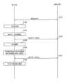
- FIG. 16is a diagram showing the operation according to the first embodiment.
- step S101the gNB 200 notifies the UE 100 of the current HFN of the MBS data.
- UE 100receives the HFN.
- step S102the receiving side PDCP entity 101 of the UE 100 stores (in memory) the HFN received in step S101.
- step S103the UE 100 starts receiving MBS data.
- the gNB 200starts transmitting MBS data before step S103.
- step S104the transmitting side PDCP entity 201 of the gNB200 transmits the first PDCP data PDU to the UE100.
- the receiving PDCP entity 101 of the UE 100receives the first PDCP data PDU.
- step S105the receiving side PDCP entity 101 of the UE 100 confirms the PDCP SN included in the header of the first PDCP data PDU received in step S104.
- step S106the receiving side PDCP entity 101 of the UE 100 reads (from memory) the HFN stored in step S102. Then, the receiving side PDCP entity 101 of the UE 100 determines the initial values of the PDCP state variables from the read HFN and the PDCP SN confirmed in step S105, and initializes the PDCP state variables. The UE 100 may delete (discard) the stored HFN from the memory after the initialization of the PDCP state variables is completed.
- step S107the transmitting side PDCP entity 201 of the gNB 200 transmits the second and subsequent PDCP data PDUs to the UE 100.
- the receiving PDCP entity 101 of the UE 100receives the second and subsequent PDCP data PDUs.
- step S108the receiving side PDCP entity 101 of the UE 100 updates the PDCP state variables according to the PDCP data PDU received in step S107.
- UE 100shall receive HFN from gNB 200 after receiving at least one PDCP data PDU from gNB 200 .
- PTM data transmissionis already in progress for another UE 100 and the UE 100 enters the session with a delay (starts reception)
- data receptionmay precede HFN reception. have a nature.
- UE 100receives at least one PDCP data PDU from gNB 200 before receiving HFN from gNB 200 .
- UE 100stores the at least one PDCP data PDU.
- the UE 100determines the initial value of the PDCP state variable from the HFN and the PDCP SN included in the first PDCP data PDU among the stored PDCP data PDUs.
- the UE 100suspends processing of MBS data received before HFN is provided (stores data), initializes PDCP state variables when HFN is provided, and performs data reception processing (PDCP processing ).
- FIG. 17is a diagram showing the operation according to the second embodiment.
- step S201the UE 100 starts receiving MBS data while the PDCP state variables have not yet been initialized.
- step S202the transmitting side PDCP entity 201 of the gNB 200 transmits at least one PDCP data PDU constituting MBS data to the UE 100.
- the receiving PDCP entity 101 of the UE 100receives the at least one PDCP data PDU.
- the receiving side PDCP entity 101 of the UE 100stores the PDCP data PDU received in step S202 in a buffer before performing PDCP processing.
- the PDCP entity 101 on the receiving sidehas a buffer in the stage prior to PDCP processing (specifically, the stage immediately after input to the PDCP entity and before performing the above-described PDCP reception processing).
- the receiving side PDCP entity 101 of the UE 100may store them in the buffer in the order received.
- the receiving side PDCP entity 101 of the UE 100receives a plurality of PDCP data PDUs in step S202
- the PDCP SNs of the PDCP data PDUsmay be rearranged in ascending (or increasing) order and stored in the buffer.
- step S204the gNB 200 notifies the UE 100 of the current HFN.
- UE 100receives the HFN.
- step S205the receiving side PDCP entity 101 of the UE 100 confirms the HFN received in step S204 and the PDCP SN included in the first PDCP data PDU stored in step S203.
- the receiving side PDCP entity 101 of the UE 100stores a plurality of PDCP data PDUs in step S203, it acquires the PDCP SN from the PDCP data PDU with the smallest PDCP SN or the PDCP data PDU with the largest PDCP SN.
- the receiving side PDCP entity 101 of the UE 100may acquire the PDCP SN from the first received PDCP data PDU.
- step S206the receiving side PDCP entity 101 of the UE 100 determines the initial values of the PDCP state variables from the HFN and PDCP SN confirmed in step S205, and initializes the PDCP state variables.
- step S207the receiving side PDCP entity 101 of the UE 100 sequentially performs PDCP processing on at least one PDCP data PDU stored in the buffer in step S203.
- step S208the transmitting PDCP entity 201 of the gNB 200 transmits PDCP data PDUs to the UE 100.
- the receiving PDCP entity 101 of the UE 100receives PDCP data PDUs.
- step S209the receiving side PDCP entity 101 of the UE 100 updates the PDCP state variables according to the PDCP data PDU received in step S208.
- the UE 100receives the HFN at the same time it receives the PDCP data PDU from the gNB 200 . Specifically, UE 100 receives from gNB 200 a PDCP data PDU having a header containing HFN. However, if the header always contains the HFN, the overhead becomes large.
- a third embodimentintroduces a variable format (eg, variable header) that allows dynamic HFN insertion.
- the header of the PDCP data PDUmay include a flag indicating that the header includes HFN.
- FIG. 18is a diagram showing the operation according to the third embodiment. It is assumed that the UE 100 is receiving or interested in receiving MBS data transmitted on PTM.
- step S301the transmitting side PDCP entity 201 of the gNB 200 transmits to the UE 100 a PDCP data PDU containing the current HFN in its header.
- the receiving PDCP entity 101 of the UE 100receives the PDCP data PDU.
- the receiving side PDCP entity 101 of the UE 100may wait to receive a PDCP data PDU that includes HFN in its header.
- the receiving side PDCP entity 101 of the UE 100may wait for the PDCP data PDU only when the gNB 200 sets the use of the PDCP data PDU.
- Such configurationmay be done by RRC signaling.
- a PDCP data PDU that includes an HFN in its headermay be defined as a PDCP data PDU with a different format from a PDCP data PDU that does not include an HFN. For example, it may be defined as an existing PDCP data PDU when there is no HFN, and as a PDCP MRB data PDU when there is an HFN.
- step S302the receiving side PDCP entity 101 of the UE 100 confirms the HFN and SN included in the PDCP data PDU received in step S301.
- step S303the receiving side PDCP entity 101 of the UE 100 determines the initial values of the PDCP state variables from the HFN and PDCP SN confirmed in step S302, and initializes the PDCP state variables.
- step S304the transmitting side PDCP entity 201 of the gNB 200 transmits PDCP data PDUs to the UE 100.
- This PDCP data PDUmay not contain an HFN.
- the receiving PDCP entity 101 of the UE 100receives PDCP data PDUs.
- step S305the receiving side PDCP entity 101 of the UE 100 updates the PDCP state variables according to the PDCP data PDU received in step S304.
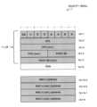
- FIG. 19is a diagram showing a PDCP data PDU according to the third embodiment.
- the PDCP data PDU with HFN shown in FIG. 19may be defined as the PDCP MRB data PDU.
- "Oct 1" of the PDCP data PDU shown in FIG. 19is a 1-bit "H” field in addition to a 1-bit "D/C" field indicating whether the PDU is a control PDU or a data PDU.
- the "H" fieldis a reserved field "R”, so "0" is normally set.
- HFNis set in the first half of "Oct 2" to "Oct 4" of the PDCP data PDU shown in FIG.
- the PDCP SNis set in the second half of "Oct 4" to "Oct 5" of the PDCP data PDU shown in FIG. Then, data is stored from "Oct 6".
- the HFN fieldis positioned before the PDCP SN field, but the HFN field may be positioned after the PDCP SN field.
- FIG. 19shows a format example in which the HFN field is provided in the header, but the HFN field may be provided after the data or after the MAC-I field. In this case, similarly to the format shown in FIG. 19, the "H" field may indicate whether or not the HFN field is added.
- the UE 100fails to receive PTM for a certain period of time due to coverage holes or interference, or when the UE 100 enters another cell (handover, cell reselection), the UE 100 receives the PDCP data PDU normally. may not be able to receive In these cases, the PDCP state variables may become out of sync and the current HFN and/or PDCP SN values may not be known.
- the HFNis still synchronized with the gNB200, so it is possible that only the initialization of the PDCP SN part will suffice. For example, if the HFN at the time of reception failure is applied as it is, and if the PDCP process fails, for example, by applying the HFN of "+1", the COUNT value is synchronized with the gNB 200, and reception may be resumed normally.
- the UE 100initializes the PDCP state variables under the condition that the UE 100 cannot normally receive the PDCP data PDU.
- the UE 100has a first condition indicating that the time for which MBS reception failure continues exceeds a predetermined time, and a second condition indicating that the number of consecutive MBS reception failures exceeds a predetermined time.
- a request signal requesting provision of HFNmay be transmitted to the gNB 200 when at least one of the two conditions is satisfied.
- UE100receives HFN transmitted from gNB200 according to a request signal.
- the UE 100may initialize PDCP state variables with initial values in response to at least one of the first condition and the second condition being satisfied.
- FIG. 20is a diagram showing the operation according to the fourth embodiment.
- step S401the UE 100 receives MBS data (PTM reception) from the gNB 200.
- MBS dataPTM reception
- the UE 100determines whether or not the condition regarding the inability to normally receive MBS data (PDCP data PDU) is satisfied.
- the UE 100is a first condition indicating that the time for which MBS reception failure continues exceeds a predetermined time, and a second condition indicating that the number of consecutive MBS reception failures exceeds a predetermined time. , determines whether at least one of the conditions is satisfied.
- the UE 100may make a determination only for reception failures in PTM (-leg).
- the UE 100may use a timer to detect that reception has failed for a certain period of time. For example, the UE 100 measures the duration of reception failure. When reception fails, the UE 100 sets a certain period (set value) in the timer and then activates the timer. The setting value of the timer may be set from the gNB 200 to the UE 100. The UE 100 may manage the timer separately for each G-RNTI or each MTCH, for example. The UE 100 stops the timer when reception is successful. On the other hand, if the timer expires, the UE 100 may decide to perform PDCP state variable initialization processing.
- the UE 100may use a counter to detect that reception has failed a certain number of times in succession. For example, the UE 100 operates a counter for each MTCH reception opportunity to measure the number of continuous reception failures. The UE 100 increments the counter by 1 when reception fails. The UE 100 may manage the counter separately for each G-RNTI or each MTCH, for example. The UE 100 initializes the count value of the counter to zero upon successful reception. On the other hand, when the count value of the counter exceeds the threshold, the UE 100 may decide to perform the PDCP state variable initialization process. The threshold may be set from the gNB 200 to the UE 100.
- the UE 100may make a determination using a combination of timers and counters.
- the UE 100performs an initialization process of PDCP state variables when the number of reception failures occurring within a certain period of time exceeds a threshold. For example, the UE 100 starts a timer and sets a counter to zero at some point. The UE 100 increments the counter by 1 for each reception failure while the timer is running. If the timer expires, the UE 100 restarts the timer and sets the counter to zero. On the other hand, if the counter exceeds the threshold, the UE 100 may decide to perform PDCP state variable initialization processing.
- the UE 100may detect the possibility of out-of-synchronization of PDCP state variables (HFN, PDCP SN). For example, the UE 100 has a discrepancy between the COUNT value stored in the receiving side PDCP entity 101 and the COUNT value derived from the PDCP SN included in the received PDCP data PDU (both COUNT values are separated by a certain amount or more). ), it may decide to perform an initialization process for the PDCP state variables.
- the security processingdeciphering/integrity verification
- the PDCP state variable initialization processingmay decide to do
- the UE 100may decide to perform PDCP state variable initialization processing when starting reception at a target whose PDCP state variables (HFN, PDCP SN) are not synchronized with the source.
- PDCP state variablesHFN, PDCP SN
- condition determination in step S402may be performed in any layer of PDCP/RLC/MAC, and the determination result may be notified to RRC.
- the UE 100transmits a request signal requesting provision of the current HFN to the gNB 200.
- the request signalmay be RRC signaling such as a UE Assistance Information message or an MBS Interest Indication message.
- the request signalmay be a PDCP control PDU, a PDCP data PDU, or a MAC CE.
- the request signalmay be a random access preamble transmitted using a special PRACH resource (a special time/frequency resource or a special preamble sequence). The method of using a random access preamble as a request signal is suitable for UE 100 in RRC idle state or RRC inactive state.
- the request signalmay include an MRB identifier that identifies an MRB that wants to provide HFN.
- the request signalmay also include an MBS session identifier (eg, TMGI) identifying the MBS session for which HFN is desired.
- the request signalmay also include a Logical Channel Identifier (LCID) identifying the logical channel on which HFN is desired to be provided.
- a PDCP data PDUis used as the request signal
- the request signalmay be a PDCP data PDU having a header with a flag bit set to "1" indicating a request for provision of HFN.
- step S404gNB 200 notifies UE 100 of the current HFN in response to the request signal received from UE 100 in step S403. UE 100 receives the HFN.
- UEs other than the UE 100 that transmitted the request signalcan also receive the HFN. Even if the other UEs that are able to perform MBS reception successfully receive the HFN, they may ignore or discard the received HFN and may not use the HFN to initialize PDCP state variables.
- step S405the UE 100 determines the initial values of the PDCP state variables from the HFN received in step S404 and the PDCP SN included in the received PDCP data PDU, and initializes the PDCP state variables. Subsequent operations are the same as in the above embodiment.
- Each of the operation flows described abovecan be implemented in combination of two or more operation flows without being limited to being implemented independently. For example, some steps of one operational flow may be added to another operational flow. Also, some steps of one operation flow may be replaced with some steps of another operation flow.
- the base stationmay be an NR base station (gNB) or a 6G base station.
- the base stationmay be a relay node such as an IAB (Integrated Access and Backhaul) node.
- IABIntegrated Access and Backhaul
- a base stationmay be a DU of an IAB node.
- the user equipmentmay be an MT (Mobile Termination) of an IAB node.
- a program that causes a computer to execute each process performed by the UE 100 or the gNB 200may be provided.
- the programmay be recorded on a computer readable medium.
- a computer readable mediumallows the installation of the program on the computer.
- the computer-readable medium on which the program is recordedmay be a non-transitory recording medium.
- the non-transitory recording mediumis not particularly limited, but may be, for example, a recording medium such as CD-ROM or DVD-ROM.
- a circuit that executes each process performed by the UE 100 or gNB 200may be integrated, and at least part of the UE 100 or gNB 200 may be configured as a semiconductor integrated circuit (chipset, SoC: System on a chip).
- the terms “based on” and “depending on,” unless expressly stated otherwise, “based only on.”does not mean The phrase “based on” means both “based only on” and “based at least in part on.” Similarly, the phrase “depending on” means both “only depending on” and “at least partially depending on.” Also, “obtain/acquire” may mean obtaining information among stored information, or it may mean obtaining information among information received from other nodes. or it may mean obtaining the information by generating the information.
- the terms “include,” “comprise,” and variations thereofare not meant to include only the recited items, and may include only the recited items or in addition to the recited items. Means that it may contain further items.
- references to elements using the "first,” “second,” etc. designations used in this disclosuredo not generally limit the quantity or order of those elements. These designations may be used herein as a convenient method of distinguishing between two or more elements. Thus, references to first and second elements do not imply that only two elements may be employed therein, or that the first element must precede the second element in any way.
- references to first and second elementsdo not imply that only two elements may be employed therein, or that the first element must precede the second element in any way.
- one MRBcan be configured with PTM only, PTP only, or both PTM and PTP. Either PTM, PTM+PTP, or PTP only can be changed by RRC signaling.
- a PDCP SRcan be generated when the bearer type of the RRC signal is changed, and how to generate a PDCP SR when it occurs.
- the SN part of the COUNT value of these variablesis set according to the SN of the packet originally received (by the UE) and optionally the HFN indicated by the gNB. .
- the MRB configurationallows the 0 RLC state variable of the PTP RLC receive window to be set to the initial value (0).
- a PDCP SRcan be generated when the bearer type of the RRC signal is changed, and how to generate a PDCP SR when it occurs.
- PDCP status reportsare triggered by RRC when the following events occur, mainly for AM DRBs (and sometimes UM DRBs).
- the receiving PDCP entityshall trigger a PDCP status report when: - Upper layers request re-establishment of the PDCP entity. - Higher layers request PDCP data recovery. - Higher layers request uplink data switching. - The upper layer reconfigures the PDCP entity to release DAPS and daps-SourceRelease is configured in TS 38.331.
- the receiving PDCP entityshall trigger a PDCP status report when: Higher layers request uplink data switching.
- PTM-only MRBsare configured only with RLC UM, but PTP-only MRBs and split MRB PTP legs are configured with RLC UM or RLC AM. These are called UM MRB and AM MRB respectively.
- the UE performance requirement for RRC reconfiguration processing delayis specified at 10ms. Therefore, the UE may miss MBS transmissions during RRC reconfiguration for bearer type change, and the missing packets need to be compensated after bearer type change. In this sense, PDCP status reports should be supported at least to meet the higher reliability requirements of certain MBS services.
- Proposal 1RAN2 should agree that PDCP status reporting is supported at least between AM MRBs and for change of lossless bearer type from UM MRB to AM MRB.
- UM MRBis not considered to require reliability when changing bearer types, that is, lossless. However, whether or not UM MRB is used for "high QoS" MBS service can actually be left to the implementation of the NW.
- PTM-only MRBsfor UEs with good radio conditions, and reconfiguring to PTP-only MRBs (or split MRBs) when the radio conditions deteriorate beyond a certain level, the NW can efficiently use resources. can be effectively operated.
- the UM DRBallows the UM DRB to trigger a PDCP status report in certain cases, it is readily apparent that the UM MRB can be configured to determine whether the NW requires a PDCP status report. be.
- the PTP-only MRB and split-MRB PTP legsneed to be configured with a DL/UL bidirectional UM, ie a DL RLC entity for MBS data reception and a UL RLC entity for PDCP status report transmission.
- Proposal 2RAN2 should agree that whether or not to use the PDCP status report when changing the UM MRB bearer type is up to the NW implementation. For that purpose, a specification that can configure PTP with DL/UL bidirectional RLC UM is required.
- the SN part of the COUNT value of these variablesis set according to the SN of the first received packet (by the UE) and optionally the HFN indicated by the gNB.
- Option 1The initial value of each state variable is simply set to the SN of the first received packet.
- the initial value of the SN part of RX_NEXTis (x+1) modulo(2 [sl-PDCP-SN-Size] ), where x is the SN of the first received PDCP data PDU'.
- the initial value of the SN part of RX_DELIVis (x - 0.5 ⁇ 2 [sl-PDCP-SN-Size-1] ) modulo (2 [sl-PDCP-SN-Size] ), x is SN of the first received PDCP Data PDU".
- RLC UM 'RX_Next_Reassemble'it is 'initialized to the SN of the first received UMD PDU containing the SN'.
- RLC UM "RX_Next_Highest”it is "initialized to the SN of the first received UMD PDU containing the SN".
- Option 3A new mechanism for RLC UM is introduced.
- RLC UM “RX_Next_Reassemble”is initialized to a value prior to “RX_Next_Highest”.
- RLC UM “RX_Next_Highest”"initialized to the SN of the first received UMD PDU containing the SN", similar to option 2 above.
- option 2the next received packet, RX_NEXT, is set to ([SN of first received packet]+1).
- RX_DELIVthe first packet not delivered to upper layers, is set to ([SN of first received packet]-[1/4 of SN length]). This means that reordering can occur even if older packets are received after the first received packet. Therefore, option 2 is considered more reliable than option 1.
- Proposal 3RAN2 agrees with PDCP to set the initial value of RX_NEXT to be ([SN of first received packet] + 1) modulo (2 ⁇ [PDCP SN length]), similar to Rel-16 V2X Should.
- Proposal 4RAN2 sets the initial value of RX_DELIV to ⁇ [SN of the first received packet]-2 ⁇ ([PDCP SN length]-2) ⁇ modulo(2 ⁇ [PDCP SN length ]) should be agreed on the PDCP.
- option 1 and option 2are exactly the same. Also, options 2 and 3 are the same in terms of RX_Next_Highest. Therefore, RAN2 should confirm that there is no other solution for the initial value of RX_Next_Highest.
- Proposal 5RAN2 should agree with RLC UM that the initial value of RX_Next_Highest is the SN of the first received packet, similar to Rel-16 V2X.
- Options 2 and 3are different with respect to RX_Next_Reassemble.
- the advantages of option 3are similar to option 2 of PDCP state variables. In other words, discarding old packets received after the first received packet can be avoided. It has also been pointed out that this problem only occurs when RLC segmentation is performed, but it is always good if packet loss is minimized.
- RAN2should discuss for RLC UM whether the initial value of RX_Next_Reassembly is the SN of the first received packet (same as Rel-16 V2X) or the previous value of RX_Next_Highest.
- Alt. 1RRC reconstruction Alt. 2: PDCP Control PDU Alt. 3: MCCH Alt. 4: SIBs Alt. 5: Header of PDCP data PDU
- Alt. 1is considered simple as the gNB needs to configure an MRB for multicast to the UE via RRC reconfiguration, i.e. the HFN is set up together with the MRB.
- RRC reconfigurationis signaling dedicated to a specific UE and is basically used only in the first delivery mode (Delivery mode 1: DM1), Alt.
- DM1Delivery mode 1
- the processingis a little heavy compared to 2.
- additional informationmay be required to indicate to which MRBs the HFN applies.
- Alt. 2is considered to be more lightweight and efficient signaling as the gNB can indicate the HFN over the PTM. Since the PDCP entity is associated with the MRB, no additional information HFN-to-MRB mapping is required. In other words, the PDCP entity that receives this PDCP control PDU should apply HFN as an initial value. This is commonly used in the first delivery mode and the second delivery mode (Delivery mode 2: DM2). Also, since the same PDCP entity processes these PDCP PDUs, the timing gap between the PDCP Control PDU and the first received packet could be minimized. However, there is concern that PDCP control PDUs are not secure.
- Alt. 3is another possibility, but MCCH is only applicable to the second delivery mode, and it is considered undesirable to impose the additional burden of acquiring MCCH on UEs receiving the first delivery mode. Also, there may be a certain timing gap between the MCCH reception and the first received packet. Furthermore, Alt. Mandatory acquisition of MCCH is not preferred as additional information may be required, similar to 1, HFN to MRB mapping.
- Alt. 4is considered as the normal provisioning method. SIB basically applies to both first delivery mode 1 and second delivery mode, but it is still unclear whether UEs connected for multicast reception are mandated to monitor SIB. . As a point of concern, Alt. 2 that the SIB is unsecured, Alt. As with 1, additional information is generated in HFN to MRB mapping, and there is a constant timing gap between the SIB reception and the first received packet. Also, when applying on-demand SI, the UE needs to send an on-demand SI request message before obtaining the SIB, which may cause HFN initialization delays.
- Alt. 5Similar advantages to 2 are seen. That is, it can be delivered in a PTM manner, no additional information is required, and it is a common solution for the first delivery mode and the second delivery mode.
- Alt. The most important advantageis theoretically the timing gap, since the first packet received by 5 carries the HFN together. However, assuming that the HFN is included in the header of the first received packet, given that the packet is starting to be sent to other UEs over the PTM, how does the gNB find the UE's first received packet? It is questionable whether we know how. Otherwise, the gNB should always include the HFN in each data packet.
- a concernis Alt. Similar to 2, the PDCP header is not secured. HFN provisioning is Alt. It is a bit strange from a concept/principle point of view as it is considered C-plane signaling as well as other alternatives including 2.
- Alt. 5uses U-plane data.
- DM1(or multicast) is generally more secure than DM2 (or broadcast). This is because the configuration is provided by dedicated signaling (and session join procedures are available in the NAS). In this sense, HFN also needs to be provided securely in DM1. In this case the simplest solution is Alt. 1, but not suitable to achieve commonality between DM1 and DM2. Alt. 2, if the PDCP Control PDU is sent on the C-RNTI, Alt. 3, Alt. 4, Alt. It is assumed that a certain degree of security can be ensured compared to 5.
- DM2should not obligate the UE to transition to CONNECTED, it is only intended for HFN acquisition.
- HFNis provided periodically in a broadcast manner (ie, using G-RNTI, MCCH-RNTI, or SI-RNTI).
- HFNAs noted above (as also summarized in the table below), it is a good balance of performance and security that HFN be provided via PDCP Control PDUs (i.e. Alt.2), and , is slightly preferred as it is a common solution for both delivery modes (ie DM1 and DM2).
- Proposal 7RAN2 should agree that the HFN initial value is provided via the PDCP Control PDU.
- Proposal 8If Proposal 7 is agreeable, RAN2 should also agree that PDCP Control PDUs (for HFN provisioning) can be sent together with G-RNTI and C-RNTI.
- the UEmay receive data before receiving HFN. This is because the reception timing of the HFN and the first received packet may differ due to out-of-order delivery (eg, retransmissions in bad radio conditions and/or retransmissions during handover, etc.). and/or depending on which option in Section 2.2.2 is selected. Moreover, the PTM transmission has already started to be sent to other UEs, so the UE can receive the data as soon as it sets the MRB.
- out-of-order deliveryeg, retransmissions in bad radio conditions and/or retransmissions during handover, etc.
- 1 UEmay receive MBS data via PTM before HFN initialization.
- RX_NEXT and RX_DELIVare (re)set to their initial values when RRC requests PDCP entity establishment, PDCP entity re-establishment, or PDCP entity suspension.
- the initialization of the COUNT valueis performed before data reception. Therefore, from a PDCP perspective, data may not be received even if the lower layers are ready to receive the data.
- the RLC layersends an RLC SDU (PDCP PDU) to the PDCP layer, the data may not be received. Even if PDCP accepts these PDCP PDUs, these PDUs will be discarded due to integrity verification failure because the HFN is still aolitic.
- PDCP PDUs from lower layersmay not be accepted or may be discarded at the PDCP layer.
- Proposal 9RAN2 should discuss how to process data packets received by the UE before HFN initialization.
- HFN Provisioning RequestAnother possible issue is whether the UE is allowed to ask the gNB for the current HFN. Especially in the case of PTM-only MRBs, the HFN can become unsynchronized if the UE fails to receive packets for a period of time, eg due to coverage holes or interference. Another case is when the UE later joins an already activated MBS session if the HFN is only provided at MBS session activation (as briefly described in Section 2.2.2). It is sometimes necessary to have an HFN.
- the UEmay not receive the next packet outside the reception window. In this case, the UE may reset all state variables to initial values.
- Proposal 10RAN2 should discuss whether the UE is allowed to request the gNB to provide the current HFN of the MBS session.
- Proposal 11RAN2 should discuss whether the state variable can be reset if the UE fails to receive an MBS session for a certain period of time.
- Lossless Mobility Operation RAN2states: "R2 aims to support lossless handover of MBS-MBS mobility for services that require it (Scenario details TBD, but at least PTP-PTP)" and " From the UE side, PDCP status reporting may also be supported.” These agreements imply a mechanism very similar to existing handovers for unicast when the MRB is configured with PTP only.
- PTM(-leg)
- MRBconfigured only with PTM and split MRB including PTP leg and PTM leg.
- a split MRBcan be regarded as a PTP-only MRB if the PTM leg is not used. Therefore, lossless handover can be easily supported based on conventional unicast handover.
- the basic procedure of the split MRBis considered as follows.
- Step 1The PTP leg of the split MRB is used with lossless dynamic switching at the source cell as needed.
- Step 2UE performs PTP-PTP handover (or like unicast handover), lossless handover.
- Step 3The PTM leg of the split MRB is used in the target cell with lossless dynamic switching if necessary.
- Step 1In the source cell, reconfigure MRB for PTM to MRB for PTP (or split MRB) due to lossless bearer type change.
- Step 2UE performs lossless handover as PTP-PTP handover (or like unicast handover).
- Step 3A lossless bearer type change allows a PTP-only MRB (or split MRB) to be reconfigured to a PTM-only MRB in the target cell if necessary.
- Lossless bearer type changeis essential for PTM-only MRB lossless handover.
- Proposal 12RAN2 should agree that MRB's basic lossless handover should always include PTP (-leg). That is, either the PTP leg of the split MRB is used, or the PTM-only MRB is reconfigured into a PTP-only MRB (or split MRB) before performing the handover.
- Proposal 13RAN2 should agree that MRB handover execution is the same as unicast handover, ie no extensions for basic lossless handover are needed.
- the next most interesting advanced procedureis direct PTM-PTM handover. That is, the UE receiving MBS over PTM (-leg) performs lossless handover. It can reduce the signaling overhead and complexity of the above basic handover procedure. That is, steps 1 and 3 can be skipped. Moreover, such direct PTM-PTM lossless handovers are expected especially in split MRBs with PTP legs. used for services that require higher reliability. However, it is already past the halfway point of the Release 17 timeframe and WID only states that it "specifies support for basic mobility with service continuity". As such, advanced lossless handover should be deferred until a future release.
- Multicast MBS Interest IndicationRAN2 currently assumes that MBS Interest Indication is supported in broadcast sessions, but not in multicast sessions.
- RAN2#115eagreed on the basic content of the MBS Interest Indication as follows.
- MBS frequency listPriority between reception of all listed MBMS frequencies and reception of any unicast bearer TMGI list If MBS frequency reporting is allowed, the MBS frequency reported by the UE is LTE Like SC-PTM, they are sorted in descending order of interest.
- the core networkinforms the gNB of the UE's interest, since there are higher layer session join procedures in the multicast session. This applies to the UE's interested MBS service. It is also possible that the gNB knows the MBS frequency and the cell that provides the MBS service of interest to the UE. However, the priority between MBS reception and unicast may not be provided by the core network as it is purely AS related information.
- the core networkprovides the MBS service of interest to the UE to the gNB, and the gNB may know the MBS frequency/cell. However, the core network and gNB may not know the UE's AS priority between MBS and unicast.
- priority informationis also useful for gNBs, such as scheduling and handover decisions, and is considered to be related to service continuity. Therefore, the UE also needs to notify the gNB of the priority information for the multicast session. In this sense, RAN2 should agree that MBS Interest Indication should be supported for multicast service/delivery mode 1 as well.
- Proposal 14RAN2 should agree that MBS Interest Indication is also supported in multicast session/first delivery mode, at least for UE to inform gNB of priority between MBS reception and unicast reception. be.
- RAN 20CN 100: UE 101 : Receiving side PDCP entity 110 : Receiving unit 120 : Transmitting unit 130 : Control unit 200 : gNB 201: transmitting side PDCP entity 210: transmitting section 220: receiving section 230: control section 240: backhaul communication section
Landscapes
- Engineering & Computer Science (AREA)
- Computer Networks & Wireless Communication (AREA)
- Signal Processing (AREA)
- Multimedia (AREA)
- Mobile Radio Communication Systems (AREA)
Abstract
Description
Translated fromJapanese本開示は、移動通信システムで用いる通信方法、ユーザ装置、及び基地局に関する。The present disclosure relates to communication methods, user equipment, and base stations used in mobile communication systems.
3GPP(3rd Generation Partnership Project)規格において、第5世代(5G)の無線アクセス技術であるNR(New Radio)の技術仕様が規定されている。NRは、第4世代(4G)の無線アクセス技術であるLTE(Long Term Evolution)に比べて、高速・大容量かつ高信頼・低遅延といった特徴を有する。3GPPにおいて、5G/NRのマルチキャストブロードキャストサービス(MBS)の技術仕様を策定する議論が行われている(例えば、非特許文献1参照)。The 3GPP (3rd Generation Partnership Project) standard defines the technical specifications of NR (New Radio), which is the fifth generation (5G) radio access technology. Compared to LTE (Long Term Evolution), which is the fourth generation (4G) radio access technology, NR has features such as high speed, large capacity, high reliability, and low delay. In 3GPP, discussions are underway to formulate technical specifications for 5G/NR multicast broadcast services (MBS) (see, for example, Non-Patent Document 1).
5G/NRのマルチキャストブロードキャストサービスは、4G/LTEのマルチキャストブロードキャストサービスよりも改善されたサービスを提供することが望まれる。It is hoped that 5G/NR multicast broadcast services will provide improved services over 4G/LTE multicast broadcast services.
そこで、本開示は、改善されたマルチキャストブロードキャストサービスを実現可能とする通信方法、ユーザ装置、及び基地局を提供することを目的とする。Therefore, an object of the present disclosure is to provide a communication method, a user equipment, and a base station that enable improved multicast broadcast services.
第1の態様に係る通信方法は、マルチキャスト・ブロードキャストサービス(MBS)データを構成する一連のPDCP(Packet Data Convergence Protocol)データPDU(Protocol Data Unit)を基地局から受信するユーザ装置で実行する通信方法であって、前記基地局が送信するPDCPデータPDUに含まれるシーケンス番号が一周する度にカウントアップされるハイパーフレーム番号を含む無線リソース制御(RRC) Reconfigurationメッセージを、前記基地局から受信することと、前記RRC Reconfigurationメッセージに含まれる前記ハイパーフレーム番号に基づいて、前記ユーザ装置が管理するPDCP状態変数の初期値を決定することと、を有する。A communication method according to a first aspect is a communication method executed by a user device that receives a series of PDCP (Packet Data Convergence Protocol) data PDUs (Protocol Data Units) constituting multicast/broadcast service (MBS) data from a base station. and receiving, from the base station, a radio resource control (RRC) Reconfiguration message containing a hyperframe number that is incremented each time the sequence number contained in the PDCP data PDU transmitted by the base station is incremented. and determining initial values of PDCP state variables managed by the user equipment based on the hyperframe number included in the RRC Reconfiguration message.
第2の態様に係るユーザ装置は、マルチキャスト・ブロードキャストサービス(MBS)データを構成する一連のPDCP(Packet Data Convergence Protocol)データPDU(Protocol Data Unit)を基地局から受信するユーザ装置であって、前記基地局が送信するPDCPデータPDUに含まれるシーケンス番号が一周する度にカウントアップされるハイパーフレーム番号を含む無線リソース制御(RRC) Reconfigurationメッセージを、前記基地局から受信する受信部と、前記RRC Reconfigurationメッセージに含まれる前記ハイパーフレーム番号に基づいて、前記ユーザ装置が管理するPDCP状態変数の初期値を決定する制御部と、を備える。A user device according to a second aspect is a user device that receives a series of PDCP (Packet Data Convergence Protocol) data PDUs (Protocol Data Units) constituting multicast broadcast service (MBS) data from a base station, A receiving unit that receives from the base station a radio resource control (RRC) Reconfiguration message containing a hyperframe number that is counted up each time the sequence number included in the PDCP data PDU sent by the base station goes around, and the RRC Reconfiguration a control unit that determines initial values of PDCP state variables managed by the user equipment based on the hyperframe number included in the message.
第3の態様に係る基地局は、マルチキャスト・ブロードキャストサービス(MBS)データを構成する一連のPDCP(Packet Data Convergence Protocol)データPDU(Protocol Data Unit)をユーザ装置に送信する基地局であって、前記基地局が送信するPDCPデータPDUに含まれるシーケンス番号が一周する度にカウントアップされるハイパーフレーム番号を含む無線リソース制御(RRC) Reconfigurationメッセージを、前記ユーザ装置に送信する送信部を備える。A base station according to a third aspect is a base station that transmits a series of PDCP (Packet Data Convergence Protocol) data PDU (Protocol Data Unit) constituting multicast broadcast service (MBS) data to a user device, It comprises a transmission unit that transmits a radio resource control (RRC) Reconfiguration message containing a hyperframe number that is counted up each time the sequence number contained in the PDCP data PDU transmitted by the base station goes around, to the user equipment.
図面を参照しながら、実施形態に係る移動通信システムについて説明する。図面の記載において、同一又は類似の部分には同一又は類似の符号を付している。A mobile communication system according to an embodiment will be described with reference to the drawings. In the description of the drawings, the same or similar parts are denoted by the same or similar reference numerals.
(移動通信システムの構成)
図1は、実施形態に係る移動通信システムの構成を示す図である。移動通信システム1は、3GPP規格の第5世代システム(5GS:5th Generation System)に準拠する。以下において、5GSを例に挙げて説明するが、移動通信システムにはLTE(Long Term Evolution)システムが少なくとも部分的に適用されてもよい。また、移動通信システムには第6世代(6G)システムが少なくとも部分的に適用されてもよい。(Configuration of mobile communication system)
FIG. 1 is a diagram showing the configuration of a mobile communication system according to an embodiment. The
移動通信システム1は、ユーザ装置(UE:User Equipment)100と、5Gの無線アクセスネットワーク(NG-RAN:Next Generation Radio Access Network)10と、5Gのコアネットワーク(5GC:5G Core Network)20とを有する。以下において、NG-RAN10を単にRAN10と呼ぶことがある。また、5GC20を単にコアネットワーク(CN)20と呼ぶことがある。The
UE100は、移動可能な無線通信装置である。UE100は、ユーザにより利用される装置であればどのような装置であっても構わない。例えば、UE100は、携帯電話端末(スマートフォンを含む)又はタブレット端末、ノートPC、通信モジュール(通信カード又はチップセットを含む)、センサ若しくはセンサに設けられる装置、車両若しくは車両に設けられる装置(Vehicle UE)、飛行体若しくは飛行体に設けられる装置(Aerial UE)である。The UE 100 is a mobile wireless communication device. The UE 100 may be any device as long as it is used by a user. For example, the UE 100 may be a mobile phone terminal (including a smartphone) or a tablet terminal, a notebook PC, a communication module (including a communication card or chipset), a sensor or a device provided in a sensor, a vehicle or a device provided in the vehicle (Vehicle UE ), an aircraft or a device (Aerial UE) provided on the aircraft.
NG-RAN10は、基地局(5Gシステムにおいて「gNB」と呼ばれる)200を含む。gNB200は、基地局間インターフェイスであるXnインターフェイスを介して相互に接続される。gNB200は、1又は複数のセルを管理する。gNB200は、自セルとの接続を確立したUE100との無線通信を行う。gNB200は、無線リソース管理(RRM)機能、ユーザデータ(以下、単に「データ」という)のルーティング機能、モビリティ制御・スケジューリングのための測定制御機能等を有する。「セル」は、無線通信エリアの最小単位を示す用語として用いられる。「セル」は、UE100との無線通信を行う機能又はリソースを示す用語としても用いられる。1つのセルは1つのキャリア周波数(以下、単に「周波数」と呼ぶ)に属する。The NG-RAN 10 includes a base station (called "gNB" in the 5G system) 200. The gNBs 200 are interconnected via an Xn interface, which is an interface between base stations. The gNB 200 manages one or more cells. The gNB 200 performs radio communication with the UE 100 that has established connection with its own cell. The gNB 200 has a radio resource management (RRM) function, a user data (hereinafter simply referred to as “data”) routing function, a measurement control function for mobility control/scheduling, and the like. A "cell" is used as a term indicating the minimum unit of a wireless communication area. A “cell” is also used as a term indicating a function or resource for radio communication with the UE 100 . One cell belongs to one carrier frequency (hereinafter simply called "frequency").
なお、gNBがLTEのコアネットワークであるEPC(Evolved Packet Core)に接続することもできる。LTEの基地局が5GCに接続することもできる。LTEの基地局とgNBとが基地局間インターフェイスを介して接続されることもできる。It should be noted that the gNB can also be connected to the EPC (Evolved Packet Core), which is the LTE core network. LTE base stations can also connect to 5GC. An LTE base station and a gNB may also be connected via an inter-base station interface.
5GC20は、AMF(Access and Mobility Management Function)及びUPF(User Plane Function)300を含む。AMFは、UE100に対する各種モビリティ制御等を行う。AMFは、NAS(Non-Access Stratum)シグナリングを用いてUE100と通信することにより、UE100のモビリティを管理する。UPFは、データの転送制御を行う。AMF及びUPFは、基地局-コアネットワーク間インターフェイスであるNGインターフェイスを介してgNB200と接続される。 5GC20 includes AMF (Access and Mobility Management Function) and UPF (User Plane Function) 300. AMF performs various mobility control etc. with respect to UE100. AMF manages the mobility of UE 100 by communicating with UE 100 using NAS (Non-Access Stratum) signaling. The UPF controls data transfer. AMF and UPF are connected to gNB 200 via NG interface, which is a base station-core network interface.
図2は、実施形態に係るUE100(ユーザ装置)の構成を示す図である。UE100は、受信部110、送信部120、及び制御部130を備える。受信部110及び送信部120は、gNB200との無線通信を行う無線通信部を構成する。FIG. 2 is a diagram showing the configuration of the UE 100 (user equipment) according to the embodiment. UE 100 includes a
受信部110は、制御部130の制御下で各種の受信を行う。受信部110は、アンテナ及び受信機を含む。受信機は、アンテナが受信する無線信号をベースバンド信号(受信信号)に変換して制御部130に出力する。The
送信部120は、制御部130の制御下で各種の送信を行う。送信部120は、アンテナ及び送信機を含む。送信機は、制御部130が出力するベースバンド信号(送信信号)を無線信号に変換してアンテナから送信する。The
制御部130は、UE100における各種の制御及び処理を行う。このような処理は、後述の各レイヤの処理を含む。制御部130は、少なくとも1つのプロセッサ及び少なくとも1つのメモリを含む。メモリは、プロセッサにより実行されるプログラム、及びプロセッサによる処理に用いられる情報を記憶する。プロセッサは、ベースバンドプロセッサと、CPU(Central Processing Unit)とを含んでもよい。ベースバンドプロセッサは、ベースバンド信号の変調・復調及び符号化・復号等を行う。CPUは、メモリに記憶されるプログラムを実行して各種の処理を行う。The
図3は、実施形態に係るgNB200(基地局)の構成を示す図である。gNB200は、送信部210、受信部220、制御部230、及びバックホール通信部240を備える。送信部210及び受信部220は、UE100との無線通信を行う無線通信部を構成する。バックホール通信部240は、CN20との通信を行うネットワーク通信部を構成する。FIG. 3 is a diagram showing the configuration of gNB 200 (base station) according to the embodiment. The
送信部210は、制御部230の制御下で各種の送信を行う。送信部210は、アンテナ及び送信機を含む。送信機は、制御部230が出力するベースバンド信号(送信信号)を無線信号に変換してアンテナから送信する。The
受信部220は、制御部230の制御下で各種の受信を行う。受信部220は、アンテナ及び受信機を含む。受信機は、アンテナが受信する無線信号をベースバンド信号(受信信号)に変換して制御部230に出力する。The receiving
制御部230は、gNB200における各種の制御及び処理を行う。このような処理は、後述の各レイヤの処理を含む。制御部230は、少なくとも1つのプロセッサ及び少なくとも1つのメモリを含む。メモリは、プロセッサにより実行されるプログラム、及びプロセッサによる処理に用いられる情報を記憶する。プロセッサは、ベースバンドプロセッサと、CPUとを含んでもよい。ベースバンドプロセッサは、ベースバンド信号の変調・復調及び符号化・復号等を行う。CPUは、メモリに記憶されるプログラムを実行して各種の処理を行う。The
バックホール通信部240は、基地局間インターフェイスであるXnインターフェイスを介して隣接基地局と接続される。バックホール通信部240は、基地局-コアネットワーク間インターフェイスであるNGインターフェイスを介してAMF/UPF300と接続される。なお、gNB200は、CU(Central Unit)とDU(Distributed Unit)とで構成され(すなわち、機能分割され)、両ユニット間がフロントホールインターフェイスであるF1インターフェイスで接続されてもよい。The
図4は、データを取り扱うユーザプレーンの無線インターフェイスのプロトコルスタックの構成を示す図である。FIG. 4 is a diagram showing the configuration of the protocol stack of the radio interface of the user plane that handles data.
ユーザプレーンの無線インターフェイスプロトコルは、物理(PHY)レイヤと、MAC(Medium Access Control)レイヤと、RLC(Radio Link Control)レイヤと、PDCP(Packet Data Convergence Protocol)レイヤと、SDAP(Service Data Adaptation Protocol)レイヤとを有する。The user plane radio interface protocol includes a physical (PHY) layer, a MAC (Medium Access Control) layer, an RLC (Radio Link Control) layer, a PDCP (Packet Data Convergence Protocol) layer, and an SDAP (Service Data Adaptation Protocol) layer. layer.
PHYレイヤは、符号化・復号、変調・復調、アンテナマッピング・デマッピング、及びリソースマッピング・デマッピングを行う。UE100のPHYレイヤとgNB200のPHYレイヤとの間では、物理チャネルを介してデータ及び制御情報が伝送される。なお、UE100のPHYレイヤは、gNB200から物理下りリンク制御チャネル(PDCCH)上で送信される下りリンク制御情報(DCI)を受信する。具体的には、UE100は、無線ネットワーク一時識別子(RNTI)を用いてPDCCHのブラインド復号を行い、復号に成功したDCIを自UE宛てのDCIとして取得する。gNB200から送信されるDCIには、RNTIによってスクランブルされたCRCパリティビットが付加されている。The PHY layer performs encoding/decoding, modulation/demodulation, antenna mapping/demapping, and resource mapping/demapping. Data and control information are transmitted between the PHY layer of the
MACレイヤは、データの優先制御、ハイブリッドARQ(HARQ:Hybrid Automatic Repeat reQuest)による再送処理、及びランダムアクセスプロシージャ等を行う。UE100のMACレイヤとgNB200のMACレイヤとの間では、トランスポートチャネルを介してデータ及び制御情報が伝送される。gNB200のMACレイヤはスケジューラを含む。スケジューラは、上下リンクのトランスポートフォーマット(トランスポートブロックサイズ、変調・符号化方式(MCS:Modulation and Coding Scheme))及びUE100への割当リソースブロックを決定する。The MAC layer performs data priority control, retransmission processing by hybrid ARQ (HARQ: Hybrid Automatic Repeat reQuest), random access procedures, and the like. Data and control information are transmitted between the MAC layer of the
RLCレイヤは、MACレイヤ及びPHYレイヤの機能を利用してデータを受信側のRLCレイヤに伝送する。UE100のRLCレイヤとgNB200のRLCレイヤとの間では、論理チャネルを介してデータ及び制御情報が伝送される。The RLC layer uses the functions of the MAC layer and PHY layer to transmit data to the RLC layer on the receiving side. Data and control information are transmitted between the RLC layer of the
PDCPレイヤは、ヘッダ圧縮・伸張、及び暗号化・復号化等を行う。The PDCP layer performs header compression/decompression, encryption/decryption, etc.
SDAPレイヤは、コアネットワークがQoS(Quality of Service)制御を行う単位であるIPフローとAS(Access Stratum)がQoS制御を行う単位である無線ベアラとのマッピングを行う。なお、RANがEPCに接続される場合は、SDAPが無くてもよい。The SDAP layer maps IP flows, which are units for QoS (Quality of Service) control by the core network, and radio bearers, which are units for QoS control by AS (Access Stratum). Note that SDAP may not be present when the RAN is connected to the EPC.
図5は、シグナリング(制御信号)を取り扱う制御プレーンの無線インターフェイスのプロトコルスタックの構成を示す図である。FIG. 5 is a diagram showing the protocol stack configuration of the radio interface of the control plane that handles signaling (control signals).
制御プレーンの無線インターフェイスのプロトコルスタックは、図4に示したSDAPレイヤに代えて、RRC(Radio Resource Control)レイヤ及びNAS(Non-Access Stratum)レイヤを有する。The radio interface protocol stack of the control plane has an RRC (Radio Resource Control) layer and a NAS (Non-Access Stratum) layer instead of the SDAP layer shown in FIG.
UE100のRRCレイヤとgNB200のRRCレイヤとの間では、各種設定のためのRRCシグナリングが伝送される。RRCレイヤは、無線ベアラの確立、再確立及び解放に応じて、論理チャネル、トランスポートチャネル、及び物理チャネルを制御する。UE100のRRCとgNB200のRRCとの間にコネクション(RRCコネクション)がある場合、UE100はRRCコネクティッド状態にある。UE100のRRCとgNB200のRRCとの間にコネクション(RRCコネクション)がない場合、UE100はRRCアイドル状態にある。UE100のRRCとgNB200のRRCとの間のコネクションがサスペンドされている場合、UE100はRRCインアクティブ状態にある。RRC signaling for various settings is transmitted between the RRC layer of the
RRCレイヤの上位に位置するNASレイヤは、セッション管理及びモビリティ管理等を行う。UE100のNASレイヤとAMF300AのNASレイヤとの間では、NASシグナリングが伝送される。なお、UE100は、無線インターフェイスのプロトコル以外にアプリケーションレイヤ等を有する。また、NASレイヤよりも下位のレイヤをASレイヤと呼ぶ。The NAS layer located above the RRC layer performs session management and mobility management. NAS signaling is transmitted between the NAS layer of
(MBSの概要)
実施形態に係るMBSの概要について説明する。MBSは、NG-RAN10からUE100に対してブロードキャスト又はマルチキャスト、すなわち、1対多(PTM:Point To Multipoint)でのデータ送信を可能とするサービスである。MBSのユースケース(サービス種別)としては、公安通信、ミッションクリティカル通信、V2X(Vehicle to Everything)通信、IPv4又はIPv6マルチキャスト配信、IPTV(Internet protocol television)、グループ通信、及びソフトウェア配信等が想定される。(Overview of MBS)
An overview of the MBS according to the embodiment will be described. MBS is a service that enables data transmission from the NG-
ブロードキャストサービスは、高信頼性のQoSを必要としないアプリケーションのために、特定のサービスエリア内のすべてのUE100に対してサービスを提供する。ブロードキャストサービスに用いるMBSセッションをブロードキャストセッションと呼ぶ。A broadcast service provides service to all
マルチキャストサービスは、すべてのUE100に対してではなく、マルチキャストサービス(マルチキャストセッション)に参加しているUE100のグループに対してサービスを提供する。マルチキャストサービスに用いるMBSセッションをマルチキャストセッションと呼ぶ。マルチキャストサービスによれば、ブロードキャストサービスに比べて、無線効率の高い方法でUE100のグループに対して同じコンテンツを提供できる。A multicast service provides a service not to all
図6は、実施形態に係るMBSトラフィック配信の概要を示す図である。FIG. 6 is a diagram showing an overview of MBS traffic distribution according to the embodiment.
MBSトラフィック(MBSデータ)は、単一のデータソース(アプリケーションサービスプロバイダ)から複数のUEに配信される。5Gコアネットワークである5G CN(5GC)20は、アプリケーションサービスプロバイダからMBSデータを受信し、MBSデータのコピーの作成(Replication)を行って配信する。MBS traffic (MBS data) is delivered from a single data source (application service provider) to multiple UEs. A 5G CN (5GC) 20, which is a 5G core network, receives MBS data from an application service provider, creates a copy of the MBS data (Replication), and distributes it.
5GC20の観点からは、5GC共有MBSトラフィック配信(5GC Shared MBS Traffic delivery)及び5GC個別MBSトラフィック配信(5GC Individual MBS Traffic delivery)の2つのマルチキャスト配信方法が可能である。From the perspective of 5GC20, two multicast delivery methods are possible: 5GC Shared MBS Traffic delivery and 5GC Individual MBS Traffic delivery.
5GC個別MBSトラフィック配信方法では、5GC20は、MBSデータパケットの単一コピーを受信し、UE100ごとのPDUセッションを介してそれらのMBSデータパケットの個別のコピーを個別のUE100に配信する。したがって、UE100ごとに1つのPDUセッションをマルチキャストセッションと関連付ける必要がある。In the 5GC individual MBS traffic delivery method, the
5GC共有MBSトラフィック配信方法では、5GC20は、MBSデータパケットの単一コピーを受信し、それらのMBSパケットの単一コピーをRANノード(すなわち、gNB200)に配信する。gNB200は、MBSトンネル接続を介してMBSデータパケットを受信し、それらを1つ又は複数のUE100に配信する。In the 5GC shared MBS traffic delivery method, the
RAN(5G RAN)10の観点からは、5GC共有MBSトラフィック配信方法における無線を介したMBSデータの送信には、PTP(Point-to-Point)及びPTM(Point-to-Multipoint)の2つの配信方法が可能である。PTPはユニキャストを意味し、PTMはマルチキャスト及びブロードキャストを意味する。From the perspective of the RAN (5G RAN) 10, the transmission of MBS data over the air in the 5GC shared MBS traffic distribution method has two distributions: Point-to-Point (PTP) and Point-to-Multipoint (PTM). A method is possible. PTP stands for unicast and PTM stands for multicast and broadcast.
PTP配信方法では、gNB200は、MBSデータパケットの個別のコピーを無線で個々のUE100に配信する。他方、PTM配信方法では、gNB200は、MBSデータパケットの単一コピーを無線でUE100のグループに配信する。gNB200は、1つのUE100に対するMBSデータの配信方法としてPTM及びPTPのどちらを用いるかを動的に決定できる。In the PTP delivery method, the
PTP配信方法及びPTM配信方法は主としてユーザプレーンに関するものである。MBSデータ配信の制御モードとしては、第1配信モード及び第2配信モードの2つの配信モードがある。The PTP and PTM delivery methods are primarily concerned with the user plane. There are two distribution modes, a first distribution mode and a second distribution mode, as MBS data distribution control modes.
図7は、実施形態に係る配信モードを示す図である。FIG. 7 is a diagram showing distribution modes according to the embodiment.
第1配信モード(Delivery mode 1:DM1)は、RRCコネクティッド状態のUE100が利用できる配信モードであって、高QoS要件のための配信モードである。第1配信モードは、MBSセッションのうちマルチキャストセッションに用いられる。但し、第1配信モードがブロードキャストセッションに用いられてもよい。第1配信モードは、RRCアイドル状態又はRRCインアクティブ状態のUE100も利用可能であってもよい。The first delivery mode (delivery mode 1: DM1) is a delivery mode that can be used by
第1配信モードにおけるMBS受信の設定は、UE固有(UE-dedicated)シグナリングにより行われる。例えば、第1配信モードにおけるMBS受信の設定は、gNB200からUE100にユニキャストで送信されるRRCメッセージであるRRC Reconfigurationメッセージ(又はRRC Releaseメッセージ)により行われる。Setting up MBS reception in the first delivery mode is done by UE-dedicated signaling. For example, MBS reception settings in the first distribution mode are performed by an RRC Reconfiguration message (or RRC Release message), which is an RRC message unicast from the
MBS受信の設定は、MBSデータを伝送するMBSトラフィックチャネルの設定に関するMBSトラフィックチャネル設定情報(以下、「MTCH設定情報」と呼ぶ)を含む。MTCH設定情報は、MBSセッションに関するMBSセッション情報(後述のMBSセッション識別子を含む)と、このMBSセッションに対応するMBSトラフィックチャネルのスケジューリング情報とを含む。MBSトラフィックチャネルのスケジューリング情報は、MBSトラフィックチャネルの間欠受信(DRX)設定を含んでもよい。間欠受信設定は、オン期間(On Duration:受信期間)を定義するタイマ値(On Duration Timer)、オン期間を延長するタイマ値(Inactivity Timer)、スケジューリング間隔もしくはDRXサイクル(Scheduling Period、DRX Cycle)、スケジューリングもしくはDRXサイクルの開始サブフレームのオフセット値(Start Offset、DRX Cycle Offest)、オン期間タイマの開始遅延スロット値(Slot Offset)、再送時までの最大時間を定義するタイマ値(Retransmission Timer)、HARQ再送のDL割り当てまでの最小間隔を定義するタイマ値(HARQ RTT Timer)のいずれか一つ以上のパラメータを含んでもよい。The MBS reception configuration includes MBS traffic channel configuration information (hereinafter referred to as "MTCH configuration information") regarding the configuration of the MBS traffic channel that transmits MBS data. The MTCH configuration information includes MBS session information (including an MBS session identifier to be described later) regarding the MBS session and scheduling information of the MBS traffic channel corresponding to this MBS session. The MBS traffic channel scheduling information may include a discontinuous reception (DRX) configuration of the MBS traffic channel. The discontinuous reception setting includes a timer value (On Duration Timer) that defines an on duration (On Duration: reception period), a timer value (Inactivity Timer) that extends the on duration, a scheduling interval or DRX cycle (Scheduling Period, DRX Cycle), Scheduling or DRX cycle start subframe offset value (Start Offset, DRX Cycle Offset), ON period timer start delay slot value (Slot Offset), timer value defining maximum time until retransmission (Retransmission Timer), HARQ It may include any one or more parameters of timer value (HARQ RTT Timer) that defines the minimum interval to DL allocation for retransmission.
なお、MBSトラフィックチャネルは論理チャネルの一種であって、MTCHと呼ばれることがある。MBSトラフィックチャネルは、トランスポートチャネルの一種である下りリンク共有チャネル(DL-SCH:Down Link―Shared CHannel)にマッピングされる。The MBS traffic channel is a kind of logical channel and is sometimes called MTCH. The MBS traffic channel is mapped to a downlink shared channel (DL-SCH: Down Link-Shared CHannel), which is a type of transport channel.
第2配信モード(Delivery mode 2:DM2)は、RRCコネクティッド状態のUE100だけではなく、RRCアイドル状態又はRRCインアクティブ状態のUE100が利用できる配信モードであって、低QoS要件のための配信モードである。第2配信モードは、MBSセッションのうちブロードキャストセッションに用いられる。但し、第2配信モードは、マルチキャストセッションにも適用可能であってもよい。The second delivery mode (Delivery mode 2: DM2) is a delivery mode that can be used not only by the
第2配信モードにおけるMBS受信の設定は、ブロードキャストシグナリングにより行われる。例えば、第2配信モードにおけるMBS受信の設定は、gNB200からUE100にブロードキャストで送信される論理チャネル、例えば、ブロードキャスト制御チャネル(BCCH)及び/又はマルチキャスト制御チャネル(MCCH)により行われる。UE100は、例えば、技術仕様で予め規定された専用のRNTIを用いてBCCH及びMCCHを受信できる。BCCH受信用のRNTIがSI-RNTIであって、MCCH受信用のRNTIがMCCH-RNTIであってもよい。 The setting for MBS reception in the second delivery mode is performed by broadcast signaling. For example, the configuration of MBS reception in the second delivery mode is done via logical channels broadcasted from the
第2配信モードにおいて、UE100は、次の3つの手順でMBSデータを受信してもよい。第1に、UE100は、gNB200からBCCH上で伝送されるSIB(MBS SIB)によりMCCH設定情報を受信する。第2に、UE100は、MCCH設定情報に基づいてgNB200からMCCHを受信する。MCCHは、MTCH設定情報を伝送する。第3に、UE100は、MTCH設定情報に基づいて、MTCH(MBSデータ)を受信する。以下において、MTCH設定情報及び/又はMCCH設定情報をMBS受信設定と呼ぶことがある。 In the second delivery mode, the
第1配信モード及び第2配信モードにおいて、UE100は、gNB200から割り当てられるグループRNTI(G-RNTI)を用いてMTCHを受信してもよい。G-RNTIは、MTCH受信用RNTIに相当する。G-RNTIは、MBS受信設定(MTCH設定情報)に含まれていてもよい。In the first distribution mode and the second distribution mode, the
なお、ネットワークは、MBSセッションごとに異なるMBSサービスを提供できる。MBSセッションは、TMGI(Temporary Mobile Group Identity)、ソーススペシフィックIPマルチキャストアドレス(アプリケーション機能やアプリケーションサーバ等のソースユニキャストIPアドレスと、宛先アドレスを示すIPマルチキャストアドレスとから成る)、セッション識別子、及びG-RNTIのうち少なくとも1つにより識別される。TMGI、ソーススペシフィックIPマルチキャストアドレス、及びセッション識別子の少なくとも1つをMBSセッション識別子と呼ぶ。TMGI、ソーススペシフィックIPマルチキャストアドレス、セッション識別子、及びG-RNTIを総括してMBSセッション情報と呼ぶ。Note that the network can provide different MBS services for each MBS session. An MBS session consists of a TMGI (Temporary Mobile Group Identity), a source-specific IP multicast address (consisting of a source unicast IP address such as an application function or application server, and an IP multicast address indicating a destination address), a session identifier, and G- Identified by at least one of the RNTIs. At least one of TMGI, source-specific IP multicast address, and session identifier is called MBS session identifier. TMGI, source-specific IP multicast address, session identifier, and G-RNTI are collectively referred to as MBS session information.
図8は、実施形態に係るUE100のMBS受信に関する内部処理の一例を示す図である。図9は、実施形態に係るUE100のMBS受信に関する内部処理の他の例を示す図である。FIG. 8 is a diagram showing an example of internal processing related to MBS reception by the
1つのMBS無線ベアラ(MRB)は、マルチキャストセッション又はブロードキャストセッションを伝送する1つの無線ベアラである。すなわち、MRBにマルチキャストセッションが対応付けられる場合と、MRBにブロードキャストセッションが対応付けられる場合とがある。 One MBS radio bearer (MRB) is one radio bearer that carries a multicast or broadcast session. That is, there are cases where an MRB is associated with a multicast session and where an MRB is associated with a broadcast session.
MRB及び対応する論理チャネル(例えば、MTCH)は、RRCシグナリングによってgNB200からUE100に設定される。MRBの設定手順は、データ無線ベアラ(DRB)の設定手順と分離されていてもよい。RRCシグナリングでは、1つのMRBを、「PTMのみ(PTM only)」、「PTPのみ(PTP only)」、又は「PTM及びPTPの両方(both PTM and PTP)」で設定できる。このようなMRBの種別はRRCシグナリングにより変更できる。The MRB and the corresponding logical channel (eg, MTCH) are set from
図8において、MRB#1にはマルチキャストセッション及び専用トラフィックチャネル(DTCH)が対応付けられ、MRB#2にはマルチキャストセッション及びMTCH#1が対応付けられ、MRB#3にはブロードキャストセッション及びMTCH#2が対応付けられる一例を示している。すなわち、MRB#1はPTPのみ(PTP only)のMRBであり、MRB#2はPTMのみ(PTM only)のMRBであり、MRB#3はPTMのみ(PTM only)のMRBである。なお、DTCHは、セルRNTI(C-RNTI)を用いてスケジューリングされる。MTCHは、G-RNTIを用いてスケジューリングされる。In FIG. 8,
UE100のPHYレイヤは、物理チャネルの1つであるPDSCH上で受信したユーザデータ(受信データ)を処理し、トランスポートチャネルの1つである下りリンク共有チャネル(DL-SCH)に流す。UE100のMACレイヤ(MACエンティティ)は、DL-SCH上で受信したデータを処理し、受信データに含まれるヘッダ(MACヘッダ)に含まれる論理チャネル識別子(LCID)に基づいて、当該受信データを対応する論理チャネル(対応するRLCエンティティ)に流す。The PHY layer of the
図9において、マルチキャストセッションと対応付けられるMRBに、DTCH及びMTCHが対応付けられる一例を示している。具体的には、1つのMRBが2つのレグに分割(スプリット)され、一方のレグがDTCHと対応付けられ、他方のレグがMTCHと対応付けられている。当該2つのレグは、PDCPレイヤ(PDCPエンティティ)において結合される。すなわち、当該MRBは、PTM及びPTPの両方(both PTM and PTP)のMRBである。このようなMRBは、スプリットMRBと呼ばれることがある。FIG. 9 shows an example in which DTCH and MTCH are associated with MRB associated with a multicast session. Specifically, one MRB is divided (split) into two legs, one leg is associated with DTCH, and the other leg is associated with MTCH. The two legs are combined at the PDCP layer (PDCP entity). That is, the MRB is an MRB of both PTM and PTP (both PTM and PTP). Such an MRB is sometimes called a split MRB.
(PDCPレイヤの動作)
図10は、実施形態に係る移動通信システム1におけるPDCPレイヤの動作を示す図である。(Operation of PDCP layer)
FIG. 10 is a diagram showing the operation of the PDCP layer in the
gNB200は、あるMBSセッションのMBSデータをPTM(マルチキャスト又はブロードキャスト)で複数のUE100(図10の例では、UE100a乃至UE100c)に送信する。各UE100のRRC状態はどのような状態(RRCコネクティッド状態、RRCアイドル状態、RRCインアクティブ状態)であってもよい。MBS配信のモードは、第1配信モード又は第2配信モードであってもよい。The
gNB200は、PDCPレイヤにおいて、当該MBSセッションと対応付けられた送信側PDCPエンティティ201(具体的には、当該MBSセッションに属するマルチキャスト無線ベアラ(MRB)と対応付けられた送信側PDCPエンティティ)を有する。送信側PDCPエンティティ201は、MBSセッションの送信を開始すると、当該MBSセッションにおけるPDCPデータPDU(Protocol Data Unit)の送信に応じて更新されるPDCP状態変数を管理する。The
各UE100は、PDCPレイヤにおいて、当該MBSセッションと対応付けられた受信側PDCPエンティティ101(具体的には、当該MBSセッションに属するMRBと対応付けられた受信側PDCPエンティティ)を有する。各受信側PDCPエンティティ101(図10の例では、受信側PDCPエンティティ101a乃至受信側PDCPエンティティ101c)は、MBSセッションの受信を開始すると、当該MBSセッションにおけるPDCPデータPDUの受信に応じて更新されるPDCP状態変数を管理する。Each
図11に示すように、PDCP状態変数は、PDCPシーケンス番号が一周する度にカウントアップされるハイパーフレーム番号(HFN)と、PDCPシーケンス番号(PDCP SN)と、からなるカウント値(COUNT値)であってもよい。例えば、COUNT値は32ビットのビット長を有し、PDCP SNは12ビット又は18ビットのビット長(SN_length)を有し、HFNはCOUNT値のビット長からPDCP SNのビット長を減じたビット長を有する。PDCP SNのビット長は、RRCシグナリングにより設定されてもよい。PDCP SNビット長は、デフォルト値(予め決められた固定値)であってもよい。なお、用語「PDCP状態変数」は、COUNT値を指す場合に限らず、PDCPレイヤで扱う各種の変数(HFN又はPDCP SN、或いはTX_NEXT、RX_NEXT、RX_DELIV及びRX_REORD等)を指す用語としても用いられる。As shown in FIG. 11, the PDCP state variable is a count value (COUNT value) consisting of a hyperframe number (HFN) that is incremented each time the PDCP sequence number goes around, and a PDCP sequence number (PDCP SN). There may be. For example, the COUNT value has a bit length of 32 bits, the PDCP SN has a bit length (SN_length) of 12 or 18 bits, and the HFN is the bit length of the COUNT value minus the bit length of the PDCP SN. have The bit length of PDCP SN may be set by RRC signaling. The PDCP SN bit length may be the default value (predetermined fixed value). Note that the term "PDCP state variable" is not limited to referring to the COUNT value, but is also used as a term to indicate various variables (HFN or PDCP SN, or TX_NEXT, RX_NEXT, RX_DELIV, RX_REORD, etc.) handled in the PDCP layer.
図12は、MBSデータを構成するPDCPデータPDUの一例を示す図である。図12に示すように、PDCPデータPDUは、PDCP SNと、データと、MAC-Iとを有する。PDCP SNは、PDCPデータPDUに順次付与されるシーケンス番号である。データは、PDCP SDU(Service Data Unit)に相当する。MAC-Iは、メッセージ認証コードに相当する。PDCPデータPDUは、MAC-Iを有していない場合がある。このように、PDCPデータPDUは、PDCP SNを有するものの、HFNを有していない。そのため、gNB200及びUE100のそれぞれは、PDCPデータPDUの送受信に応じてHFNを更新、具体的には、PDCPシーケンス番号が一周する度にカウントアップする必要がある。FIG. 12 is a diagram showing an example of PDCP data PDUs forming MBS data. As shown in FIG. 12, the PDCP data PDU has PDCP SN, data, and MAC-I. PDCP SN is a sequence number sequentially assigned to PDCP data PDUs. The data corresponds to a PDCP SDU (Service Data Unit). MAC-I corresponds to a message authentication code. A PDCP data PDU may not have a MAC-I. Thus, a PDCP data PDU has a PDCP SN but no HFN. Therefore, each of the
図13は、UE100(受信側PDCPエンティティ101)において受信したPDCPデータPDUのCOUNT値であるRCVD_COUNTを特定する動作を示す図である。ここで、受信したPDCPデータPDUに含まれるPDCP SNをRCVD_SNと呼ぶ。FIG. 13 is a diagram showing the operation of identifying RCVD_COUNT, which is the COUNT value of PDCP data PDUs received in UE 100 (receiving side PDCP entity 101). Here, the PDCP SN included in the received PDCP data PDU is called RCVD_SN.
第1に、
RCVD_SN<SN(RX_DELIV)-Window_Size
である場合、
RCVD_HFN=HFN(RX_DELIV)+1
である。ここで、RX_DELIVは、受信待ちであって、未だ上位レイヤに提供していないPDCP SDUのうち最も古いものを表す変数である。RX_DELIVの初期値はゼロである。なお、PTM受信においては、RX_DELIVの初期値は、最初に受信したパケットのSNを用いてセットされてもよい。Window_Sizeは、リオーダリングウィンドウのサイズを示す定数である。First,
RCVD_SN<SN(RX_DELIV) - Window_Size
If it is,
RCVD_HFN=HFN(RX_DELIV)+1
is. Here, RX_DELIV is a variable representing the oldest PDCP SDU waiting for reception and not yet provided to the upper layer. The initial value of RX_DELIV is zero. Note that in PTM reception, the initial value of RX_DELIV may be set using the SN of the first received packet. Window_Size is a constant that indicates the size of the reordering window.
第2に、
RCVD_SN≧SN(RX_DELIV)+Window_Size
である場合、
RCVD_HFN=HFN(RX_DELIV)-1
である。Second,
RCVD_SN≧SN(RX_DELIV)+Window_Size
If it is,
RCVD_HFN=HFN(RX_DELIV)-1
is.
第3に、上記のいずれの条件も満たされない場合、
RCVD_HFN=HFN(RX_DELIV)
である。Third, if none of the above conditions are met,
RCVD_HFN=HFN(RX_DELIV)
is.
そして、
RCVD_COUNT=[RCVD_HFN,RCVD_SN]
にセットされる。and,
RCVD_COUNT=[RCVD_HFN, RCVD_SN]
is set to
図14は、UE100の受信側PDCPエンティティ101の動作の一例を示す図である。14 is a diagram showing an example of the operation of the receiving side PDCP entity 101 of the
まず、受信側PDCPエンティティ101は、PDCP PDU(PDCPデータPDU)を受信すると、当該PDCP PDUに対して、カウント値(RCVD_COUNT)を用いたセキュリティ処理(具体的には、deciphering/integrity verification)を行い(ステップS12)、integrity verificationに失敗した場合(ステップS12:Yes)、上位レイヤにintegrity verification失敗を通知するとともに当該PDCP PDUを破棄する(ステップS13)。First, when receiving a PDCP PDU (PDCP data PDU), the receiving side PDCP entity 101 performs security processing (specifically, deciphering/integrity verification) using the count value (RCVD_COUNT) on the PDCP PDU. (Step S12) If the integrity verification fails (Step S12: Yes), the upper layer is notified of the integrity verification failure and the PDCP PDU is discarded (Step S13).
受信側PDCPエンティティ101は、integrity verificationに成功した場合(ステップS12:No)、カウント値(RCVD_COUNT)がRX_DELIVよりも小さい場合(ステップS14:Yes)、又は、RCVD_COUNTが受信済みである場合(ステップS16:Yes)、当該PDCP PDUを破棄する(ステップS15)。The PDCP entity 101 on the receiving side, if the integrity verification is successful (step S12: No), if the count value (RCVD_COUNT) is smaller than RX_DELIV (step S14: Yes), or if the RCVD_COUNT has been received (step S16 : Yes), discard the relevant PDCP PDU (step S15).
次に、受信側PDCPエンティティ101は、破棄しなかったPDCP PDUを受信バッファに格納し(ステップS17)、「RCVD_COUNT≧RX_NEXT」である場合(ステップS18:Yes)、RX_NEXT=RCVD_COUNT+1に更新する(ステップS19)。ここで、RX_NEXTは、次に受信することが期待されるPDCP SDUのカウント値(RCVD_COUNT)を示す変数である。RX_NEXTの初期値はゼロである。なお、PTM受信においては、RX_NEXTの初期値は、最初に受信したパケットのSNを用いてセットされてもよい。Out-of-order deliveryが設定(Configured)されている場合(ステップS20:Yes)、受信側PDCPエンティティ101は、当該PDCP PDUをヘッダ逆圧縮後、上位レイヤに渡す(ステップS21)。具体的には、受信側PDCPエンティティ101は、RRCで“outOfOrderDelivery”が設定されている場合に、ステップS21の動作を行う。Out of order deliveryは、順序制御を行わずに上位レイヤにパケットを渡す動作である。よって、ステップS21のように、パケットを受信してバッファに格納したら直ぐに上位レイヤに当該パケットを渡す。なお、ステップS20が”No”の場合、順序制御を行うことになる。Next, the receiving side PDCP entity 101 stores the PDCP PDUs that have not been discarded in the reception buffer (step S17), and if "RCVD_COUNT≧RX_NEXT" (step S18: Yes), updates RX_NEXT=RCVD_COUNT+1 (step S19). Here, RX_NEXT is a variable that indicates the count value (RCVD_COUNT) of PDCP SDUs expected to be received next. The initial value of RX_NEXT is zero. Note that in PTM reception, the initial value of RX_NEXT may be set using the SN of the first received packet. If Out-of-order delivery is configured (step S20: Yes), the receiving side PDCP entity 101 passes the PDCP PDU to the upper layer after header decompression (step S21). Specifically, the PDCP entity 101 on the receiving side performs the operation of step S21 when "outOfOrderDelivery" is set in RRC. Out of order delivery is the operation of passing packets to the upper layer without performing order control. Therefore, as in step S21, as soon as the packet is received and stored in the buffer, the packet is transferred to the upper layer. In addition, when step S20 is "No", order control will be performed.
受信側PDCPエンティティ101は、「RCVD_COUNT=RX_DELIV」である場合(ステップS22:Yes)、COUNT=RX_DELIVから始まる連続するCOUNTの全てのPDCP SDUをヘッダ逆圧縮後、上位レイヤに渡し(ステップS23)、RX_DELIVを、上位レイヤに渡していない最初の(最も若い)COUNT値に更新する(ステップS24)。If "RCVD_COUNT=RX_DELIV" (step S22: Yes), the receiving side PDCP entity 101 passes all PDCP SDUs of consecutive COUNT starting from COUNT=RX_DELIV to the upper layer after header decompression (step S23), RX_DELIV is updated to the first (youngest) COUNT value that has not been passed to the upper layer (step S24).
受信側PDCPエンティティ101は、T-Reorderingが動作中であって、「RX_DELIV≧RX_REORD」である場合(ステップS25:Yes)、T-Reorderingをstop及びresetする(ステップS26)。ここで、T-Reorderingは、PDCPデータPDUの欠落を検出するために用いるタイマである。RX_REORDは、T-ReorderingをトリガしたPDCPデータPDUに関連付けられたCOUNT値に続くCOUNT値を示す変数である。If T-Reordering is in operation and "RX_DELIV≧RX_REORD" (step S25: Yes), the receiving side PDCP entity 101 stops and resets T-Reordering (step S26). Here, T-Reordering is a timer used to detect missing PDCP data PDUs. RX_REORD is a variable that indicates the COUNT value following the COUNT value associated with the PDCP data PDU that triggered T-Reordering.
受信側PDCPエンティティ101は、T-Reorderingが停止中であって、「RX_DELIV<RX_REORD」である場合(ステップS27:Yes)、RX_REORD=RX_NEXTに更新するとともにT-Reorderingを始動(start)する(ステップS28)。If T-Reordering is stopped and "RX_DELIV<RX_REORD" (step S27: Yes), the receiving side PDCP entity 101 updates RX_REORD=RX_NEXT and starts T-Reordering (step S28).
(移動通信システムの動作)
一般的に、PDCP状態変数の初期値はゼロであり、gNB200(送信側PDCPエンティティ201)からUE100(受信側PDCPエンティティ101)へのデータ送信が開始されると、gNB200(送信側PDCPエンティティ201)及びUE100(受信側PDCPエンティティ101)で同期してPDCP状態変数が更新される。(Operation of mobile communication system)
In general, the initial value of the PDCP state variable is zero, and when data transmission from gNB 200 (transmitting PDCP entity 201) to UE 100 (receiving PDCP entity 101) starts, gNB 200 (transmitting PDCP entity 201) and PDCP state variables are updated synchronously in the UE 100 (receiving side PDCP entity 101).
しかしながら、図10に示すようなシナリオにおいて、UE100(UE100a乃至UE100cのいずれか)は、必ずしも、gNB200がMBSセッション(マルチキャストセッション又はブロードキャストセッション)の提供を開始した時点からMBS受信を開始できるとは限らず、gNB200(送信側PDCPエンティティ201)及びUE100(受信側PDCPエンティティ101)でPDCP状態変数が非同期の状態になり、上述のようなPDCPレイヤ動作を適切に実行できないという問題がある。例えば、いずれかのUE100は、当該gNB200が提供するMBSセッションの途中からMBS受信を開始し得る。そのようなUE100は、他のgNB200(他のセル)からセル変更(例えば、セル再選択又はハンドオーバ)してきたUE100でもあり得る。However, in the scenario as shown in FIG. 10, the UE 100 (one of the
図15は、実施形態に係るUE100の動作を示す図である。実施形態において、UE100の受信側PDCPエンティティ101は、gNB200からPTMで送信されるMBSデータを構成する一連のPDCPデータPDUをgNB200から受信する。PDCPデータPDUは、PDCP MRBデータPDUと呼ばれてもよい。FIG. 15 is a diagram showing the operation of the
ステップS1において、特定のMRBの受信を行うUE100は、gNB200が送信するPDCPデータPDUに含まれるシーケンス番号(PDCP SN)が一周する度にカウントアップされるHFN(具体的には、当該特定のMRBにおける現在(最新)のHFN)をgNB200から受信する。In step S1, the
ステップS1に先立ち、UE100は、HFNの提供をgNB200に要求してもよい。UE100は、MBSデータ(PDCPデータPDU)を正常受信できないことに関する条件が満たされたことに応じて、HFNの提供をgNB200に要求してもよい。例えば、UE100は、MBS受信の失敗が継続する時間が所定時間を超えたことを示す第1条件、及びMBS受信を連続して失敗した回数が所定時間を超えたことを示す第2条件のうち、少なくとも一方の条件が満たされたことに応じて、HFNの提供をgNB200に要求してもよい。或いは、UE100は、現在(最新)のHFNの情報を有していないことを示す第3条件が満たされたことに応じて、HFNの提供をgNB200に要求してもよい。例えば、UE100は、ブロードキャストセッションについて途中から受信に興味を持ったこと又は途中から受信を開始したことなどにより、現在のHFNを有していない場合、HFNの提供をgNB200に要求してもよい。このような要求信号の構成例については、第4実施例において説明する。Prior to step S1, the
ステップS1において、UE100の受信側PDCPエンティティ101は、HFNを含むPDCP制御PDU、又はHFNをヘッダに含むPDCPデータPDUをgNB200の送信側PDCPエンティティ201から受信してもよい。PHYレイヤにおいて、当該PDCP制御PDUの伝送には、複数UE向けのRNTI(例えば、G-RNTI、MCCH-RNTI、SI-RNTI等)が用いられてもよい。また、当該PDCP制御PDUの伝送には、単一UE向けのRNTI(例えば、C-RNTI)が用いられてもよい。UE100は、当該特定のMRBと対応付けられた受信側PDCPエンティティ101においてのみ当該HFNを適用する。In step S1, the receiving side PDCP entity 101 of the
ステップS1において、UE100のRRCエンティティは、HFNを含むメッセージ(例えば、RRC Reconfigurationメッセージ、SIB、又はMCCH)をgNB200のRRCエンティティから受信してもよい。当該メッセージは、HFNと、当該HFNと対応付けられたMRB識別子、MBSサービス識別子(例えば、TMGI)及び/又は論理チャネル識別子(LCID)とを含んでもよい。UE100は、当該メッセージに含まれるMRB識別子及び/又はMBSサービス識別子が示すMRBと対応付けられた受信側PDCPエンティティ101においてのみ当該HFNを適用する。なお、SIBがHFNを含む場合、HFNの変更によるValue Tagのインクリメントは行わなくてもよい。In step S1, the RRC entity of
ステップS1において、UE100のMACエンティティは、HFNを含むMAC制御要素(MAC CE)をgNB200のMACエンティティから受信してもよい。PHYレイヤにおいて、当該PDCP制御PDUの伝送には、複数UE向けのRNTI(例えば、G-RNTI、MCCH-RNTI、SI-RNTI等)が用いられてもよい。また、当該PDCP制御PDUの伝送には、単一UE向けのRNTI(例えば、C-RNTI)が用いられてもよい。当該MAC CEは、HFNと、当該HFNと対応付けられたMRB識別子、MBSサービス識別子(例えば、TMGI)及び/又は論理チャネル識別子(LCID)とを含んでもよい。UE100は、当該メッセージに含まれるMRB識別子及び/又はMBSサービス識別子が示すMRBと対応付けられた受信側PDCPエンティティ101においてのみ当該HFNを適用する。In step S1, the MAC entity of UE100 may receive a MAC control element (MAC CE) including HFN from the MAC entity of gNB200. In the PHY layer, an RNTI for multiple UEs (eg, G-RNTI, MCCH-RNTI, SI-RNTI, etc.) may be used for transmission of the PDCP control PDU. Also, a single UE-oriented RNTI (eg, C-RNTI) may be used for transmission of the PDCP control PDU. The MAC CE may include an HFN and an MRB identifier, MBS service identifier (eg, TMGI) and/or logical channel identifier (LCID) associated with the HFN. The
ステップS2において、UE100の受信側PDCPエンティティ101は、ステップS1でgNB200から受信したHFNと、gNB200からUE100が受信するPDCPデータPDUに含まれるPDCP SNとから、UE100(受信側PDCPエンティティ101)が管理するPDCP状態変数の初期値を決定する。例えば、UE100(受信側PDCPエンティティ101)は、ステップS1でgNB200から受信したHFNと、gNB200からUE100が受信するPDCPデータPDUに含まれるPDCP SNとを結合した結果に応じてPDCP状態変数(例えば、RX_NEXT、RX_DELIV)の初期値を決定する。ここで、UE100は、RX_NEXTの初期値を
(x +1) modulo (2[sl-PDCP-SN-Size])
により決定し、RX_DELIVの初期値を
(x - 0.5 × 2[sl-PDCP-SN-Size-1]) modulo (2[sl-PDCP-SN-Size])
により決定してもよい。但し、xは、最初に受信したパケットのSNである。In step S2, the receiving side PDCP entity 101 of the
and the initial value of RX_DELIV is (x - 0.5 × 2[sl-PDCP-SN-Size-1] ) modulo (2[sl-PDCP-SN-Size] )
may be determined by where x is the SN of the first received packet.
ステップS3において、UE100の受信側PDCPエンティティ101は、ステップS2で決定した初期値によってPDCP状態変数を初期化する。すなわち、UE100の受信側PDCPエンティティ101は、ステップS2で決定した初期値をPDCP状態変数としてセットする。In step S3, the receiving side PDCP entity 101 of the
なお、UE100は、MBSデータ(PDCPデータPDU)を正常受信できないことに関する条件(例えば、上述の第1条件乃至第3条件のいずれか)が満たされたことに応じて、実施形態に係る動作を実行してもよい。すなわち、UE100は、PDCP状態変数の同期外れが生じた可能性があると判定できる状況下において、実施形態に係る動作を実行してもよい。UE100は、第1条件乃至第3条件のいずれの条件も満たされない場合、ステップS1でgNB200から受信するHFNを無視又は破棄してもよい。Note that the
実施形態に係る動作によれば、gNB200がMBSセッションの提供を開始した時点からUE100がMBS受信を開始できない場合であっても、gNB200(送信側PDCPエンティティ201)及びUE100(受信側PDCPエンティティ101)でPDCP状態変数を同期させることができ、上述のようなPDCPレイヤ動作を適切に実行可能になる。According to the operation according to the embodiment, even if the
実施形態に係る動作は、MBSセッションの途中からMBS受信を開始するUE100が実行する場合に限らず、他のgNB200(他のセル)からセル変更(例えば、セル再選択又はハンドオーバ)してきたUE100が実行してもよい。セル変更元である当該他のgNB200(他のセル)をソースと呼び、セル変更先であるgNB200(セル)をターゲットと呼ぶ。セル間(ソース及びターゲット間)でHFNが同期していない場合、PTMで送信されるMBSデータを受信するUE100は、上述の実施形態に係る動作を実行してもよい。The operation according to the embodiment is not limited to the case where the
この場合、セル間でHFNが同期していないことを、ソース及び/又はターゲットからUE100へ通知してもよい。例えば、ソース及び/又はターゲットは、HFNが同期していない隣接セルのセル識別子をUE100に通知してもよい。もしくは、ソース及び/又はターゲットは、HFNが同期している隣接セルのセル識別子をUE100に通知してもよい。UE100は、当該通知に基づいて、ターゲットに移動した際に(例えば、ターゲットからMBSデータ受信を開始した際に)上述の実施形態に係る動作を実行するか否かを決定してもよい。UE100は、当該通知に基づいて、セル間(ソース及びターゲット間)でHFNが同期していないと判定した場合に限り、上述の実施形態に係る動作を実行すると決定してもよい。In this case, the source and/or target may notify the
(実施例)
上述の実施形態に係る動作を前提として、第1実施例乃至第4実施例について説明する。これらの実施例において、2以上の実施例を組み合わせて実施してもよい。(Example)
Assuming the operation according to the above embodiment, the first to fourth examples will be described. In these examples, two or more examples may be combined and implemented.
(1)第1実施例
第1実施例において、UE100は、gNB200から最初のPDCPデータPDUを受信する前に、gNB200からHFNを受信するものとする。(1) First Example In the first example,
第1に、UE100は、gNB200から受信したHFNを記憶する。第2に、UE100は、HFNをgNB200から受信した後に、gNB200から最初のPDCPデータPDUを受信する。第3に、UE100は、記憶されたHFNと、最初のPDCPデータPDUに含まれるPDCP SNとから、PDCP状態変数の初期値を決定する。First, the
図16は、第1実施例に係る動作を示す図である。FIG. 16 is a diagram showing the operation according to the first embodiment.
ステップS101において、gNB200は、MBSデータの現在のHFNをUE100に通知する。UE100は、当該HFNを受信する。In step S101, the
ステップS102において、UE100の受信側PDCPエンティティ101は、ステップS101で受信したHFNを(メモリに)記憶する。In step S102, the receiving side PDCP entity 101 of the
ステップS103において、UE100は、MBSデータの受信を開始する。なお、gNB200は、ステップS103よりも前にMBSデータの送信を開始している。In step S103, the
ステップS104において、gNB200の送信側PDCPエンティティ201は、最初のPDCPデータPDUをUE100に送信する。UE100の受信側PDCPエンティティ101は、最初のPDCPデータPDUを受信する。In step S104, the transmitting
ステップS105において、UE100の受信側PDCPエンティティ101は、ステップS104で受信した最初のPDCPデータPDUのヘッダに含まれるPDCP SNを確認する。In step S105, the receiving side PDCP entity 101 of the
ステップS106において、UE100の受信側PDCPエンティティ101は、ステップS102で記憶したHFNを(メモリから)読みだす。そして、UE100の受信側PDCPエンティティ101は、読み出したHFNと、ステップS105で確認したPDCP SNとから、PDCP状態変数の初期値を決定し、PDCP状態変数を初期化する。UE100は、PDCP状態変数の初期化が完了した後、記憶していたHFNをメモリから削除(破棄)してもよい。In step S106, the receiving side PDCP entity 101 of the
ステップS107において、gNB200の送信側PDCPエンティティ201は、2つ目以降のPDCPデータPDUをUE100に送信する。UE100の受信側PDCPエンティティ101は、2つ目以降のPDCPデータPDUを受信する。In step S107, the transmitting
ステップS108において、UE100の受信側PDCPエンティティ101は、ステップS107で受信したPDCPデータPDUに応じてPDCP状態変数を更新する。In step S108, the receiving side PDCP entity 101 of the
(2)第2実施例
第2実施例において、UE100は、gNB200から少なくとも1つのPDCPデータPDUを受信した後に、gNB200からHFNを受信するものとする。例えば、PTMデータ送信が、他のUE100のために既に実施中の状況で、UE100が遅れてセッションに入ってきた(受信を開始した)場合、HFN受信よりもデータ受信の方が先になる可能性がある。(2) Second Example In the second example,
第1に、UE100は、HFNをgNB200から受信する前に、少なくとも1つのPDCPデータPDUをgNB200から受信する。第2に、UE100は、当該少なくとも1つのPDCPデータPDUを記憶する。第3に、UE100は、HFNをgNB200から受信した後に、当該HFNと、記憶されたPDCPデータPDUのうち最初のPDCPデータPDUに含まれるPDCP SNとから、PDCP状態変数の初期値を決定する。First,
すなわち、UE100は、HFNが提供される前に受信したMBSデータの処理を保留し(データを記憶し)、HFNが提供された時点でPDCP状態変数の初期化を行い、データ受信処理(PDCP処理)を開始する。That is, the
図17は、第2実施例に係る動作を示す図である。FIG. 17 is a diagram showing the operation according to the second embodiment.
ステップS201において、UE100は、PDCP状態変数の初期化をまだ実施していない状況で、MBSデータの受信を開始する。In step S201, the
ステップS202において、gNB200の送信側PDCPエンティティ201は、MBSデータを構成する少なくとも1つのPDCPデータPDUをUE100に送信する。UE100の受信側PDCPエンティティ101は、当該少なくとも1つのPDCPデータPDUを受信する。In step S202, the transmitting
ステップS203において、UE100の受信側PDCPエンティティ101は、PDCP処理を行う前の段階で、ステップS202で受信したPDCPデータPDUをバッファに記憶する。例えば、受信側PDCPエンティティ101は、PDCP処理を行う前段(具体的には、当該PDCPエンティティの入力直後であって、上述のPDCP受信処理を行う前の段階)にバッファを有するものとする。UE100の受信側PDCPエンティティ101は、ステップS202で複数のPDCPデータPDUを受信した場合、受信した順番にバッファに格納してもよい。また、UE100の受信側PDCPエンティティ101は、ステップS202で複数のPDCPデータPDUを受信した場合、当該PDCPデータPDUのPDCP SNが小さい(又は大きい)順に並べ替えてバッファに格納してもよい。In step S203, the receiving side PDCP entity 101 of the
その後、ステップS204において、gNB200は、現在のHFNをUE100に通知する。UE100は、当該HFNを受信する。After that, in step S204, the
ステップS205において、UE100の受信側PDCPエンティティ101は、ステップS204で受信したHFNと、ステップS203で記憶した最初のPDCPデータPDUに含まれるPDCP SNとを確認する。ここで、UE100の受信側PDCPエンティティ101は、ステップS203で複数のPDCPデータPDUを記憶している場合、PDCP SNが最も小さいPDCPデータPDUもしくはPDCP SNが最も大きいPDCPデータPDUからPDCP SNを取得してもよい。もしくは、UE100の受信側PDCPエンティティ101は、最初に受信したPDCPデータPDUからPDCP SNを取得してもよい。In step S205, the receiving side PDCP entity 101 of the
ステップS206において、UE100の受信側PDCPエンティティ101は、ステップS205で確認したHFN及びPDCP SNから、PDCP状態変数の初期値を決定し、PDCP状態変数を初期化する。In step S206, the receiving side PDCP entity 101 of the
ステップS207において、UE100の受信側PDCPエンティティ101は、ステップS203でバッファに格納した少なくとも1つのPDCPデータPDUに対して順次PDCP処理を行う。In step S207, the receiving side PDCP entity 101 of the
ステップS208において、gNB200の送信側PDCPエンティティ201は、PDCPデータPDUをUE100に送信する。UE100の受信側PDCPエンティティ101は、PDCPデータPDUを受信する。In step S208, the transmitting
ステップS209において、UE100の受信側PDCPエンティティ101は、ステップS208で受信したPDCPデータPDUに応じてPDCP状態変数を更新する。In step S209, the receiving side PDCP entity 101 of the
(3)第3実施例
上述の第1実施例及び第2実施例において、PDCPデータPDU及びHFNが別々にgNB200から提供されることを主として想定しており、提供されるHFNとPDCPデータPDUとの間に提供タイミングのギャップが発生する。そのため、PDCP SNが一巡(wrap around)する近辺のタイミングでgNB200がHFNを送信すると、gNB200とUE10と0の間でHFNの同期外れ(desync)が発生してしまう可能性がある。(3) Third embodiment In the first and second embodiments described above, it is mainly assumed that the PDCP data PDU and HFN are separately provided from the
PDCPデータPDUのヘッダ中でHFNを送信することにより、このような問題を解決可能である。第3実施例において、UE100は、gNB200からPDCPデータPDUを受信すると同時にHFNを受信する。具体的には、UE100は、HFNを含むヘッダを有するPDCPデータPDUをgNB200から受信する。但し、当該ヘッダに常にHFNを含める場合、オーバーヘッドが大きくなる。第3実施例では、HFNを動的に挿入できるような可変フォーマット(例えば、可変ヘッダ)を導入する。例えば、PDCPデータPDUのヘッダには、当該ヘッダにHFNが含まれていることを示すフラグを含めることが可能な構成とする。By sending the HFN in the header of PDCP data PDUs, such problems can be resolved. In the third embodiment, the
図18は、第3実施例に係る動作を示す図である。UE100は、PTMで送信されるMBSデータを受信中又は受信に興味を持っているものとする。FIG. 18 is a diagram showing the operation according to the third embodiment. It is assumed that the
ステップS301において、gNB200の送信側PDCPエンティティ201は、現在のHFNをヘッダに含むPDCPデータPDUをUE100に送信する。UE100の受信側PDCPエンティティ101は、当該PDCPデータPDUを受信する。In step S301, the transmitting
ステップS301に先立ち、UE100の受信側PDCPエンティティ101は、HFNをヘッダに含むPDCPデータPDUの受信を待ち受けてもよい。UE100の受信側PDCPエンティティ101は、当該PDCPデータPDUを使用することをgNB200から設定された場合に限り、当該PDCPデータPDUを待ち受けてもよい。このような設定は、RRCシグナリングによりなされてもよい。Prior to step S301, the receiving side PDCP entity 101 of the
HFNをヘッダに含むPDCPデータPDUは、HFNを含まないPDCPデータPDUと別のフォーマットのPDCPデータPDUとして定義されてもよい。例えば、HFN無しの場合は既存PDCPデータPDU、HFN有りの場合はPDCP MRBデータPDUと定義されてもよい。A PDCP data PDU that includes an HFN in its header may be defined as a PDCP data PDU with a different format from a PDCP data PDU that does not include an HFN. For example, it may be defined as an existing PDCP data PDU when there is no HFN, and as a PDCP MRB data PDU when there is an HFN.
ステップS302において、UE100の受信側PDCPエンティティ101は、ステップS301で受信したPDCPデータPDUに含まれるHFN及びSNを確認する。In step S302, the receiving side PDCP entity 101 of the
ステップS303において、UE100の受信側PDCPエンティティ101は、ステップS302で確認したHFN及びPDCP SNから、PDCP状態変数の初期値を決定し、PDCP状態変数を初期化する。In step S303, the receiving side PDCP entity 101 of the
ステップS304において、gNB200の送信側PDCPエンティティ201は、PDCPデータPDUをUE100に送信する。このPDCPデータPDUは、HFNを含まないものであってもよい。UE100の受信側PDCPエンティティ101は、PDCPデータPDUを受信する。In step S304, the transmitting
ステップS305において、UE100の受信側PDCPエンティティ101は、ステップS304で受信したPDCPデータPDUに応じてPDCP状態変数を更新する。In step S305, the receiving side PDCP entity 101 of the
図19は、第3実施例に係るPDCPデータPDUを示す図である。図19に示すHFN有りのPDCPデータPDUは、PDCP MRBデータPDUと定義されてもよい。なお、PDCP SNのビット長が12ビットである一例を示している。FIG. 19 is a diagram showing a PDCP data PDU according to the third embodiment. The PDCP data PDU with HFN shown in FIG. 19 may be defined as the PDCP MRB data PDU. An example in which the bit length of the PDCP SN is 12 bits is shown.
図19に示すPDCPデータPDUの「Oct 1」は、当該PDUが制御PDUであるか又はデータPDUであるかを示す1ビットの「D/C」フィールドに加えて、1ビットの「H」フィールドを有する。「H」フィールドに“1”がセットされる場合、HFN入りのフォーマットであることを示し、「H」フィールドに“0”がセットされる場合、HFN無しのフォーマット、すなわち、既存のPDCPデータPDUフォーマットであることを示す。なお、既存のPDCPデータPDUでは、「H」フィールドは予約フィールド“R”であるため、通常は“0”がセットされる。図19に示すPDCPデータPDUの「Oct 2」乃至「Oct 4」の前半部分には、HFNがセットされる。図19に示すPDCPデータPDUの「Oct 4」の後半部分乃至「Oct 5」には、PDCP SNがセットされる。そして、「Oct 6」からデータが格納される。"
図19に示すフォーマット例では、HFNフィールドがPDCP SNフィールドよりも前に位置しているが、HFNフィールドは、PDCP SNフィールドよりも後に位置してもよい。また、図19において、HFNフィールドをヘッダに設けるフォーマット例を示しているが、HFNフィールドをデータの後、もしくはMAC-Iフィールドの後に設けてもよい。この場合、図19に示すフォーマットと同様に、「H」フィールドによって、HFNフィールドが付与されているか否かを通知してもよい。In the format example shown in FIG. 19, the HFN field is positioned before the PDCP SN field, but the HFN field may be positioned after the PDCP SN field. Also, FIG. 19 shows a format example in which the HFN field is provided in the header, but the HFN field may be provided after the data or after the MAC-I field. In this case, similarly to the format shown in FIG. 19, the "H" field may indicate whether or not the HFN field is added.
(4)第4実施例
UE100がカバレッジホールや干渉などにより一定期間PTM受信に失敗した場合、又はUE100が別セルに入った場合(ハンドオーバ、セル再選択)において、UE100は、PDCPデータPDUを正常に受信できなくなる虞がある。これらの場合、PDCP状態変数の同期が外れてしまい、現在のHFN及び/又はPDCP SN値が分からなくなる可能性がある。(4) Fourth Embodiment When the
但し、受信失敗した期間がそれほど長時間でない場合、HFNはまだgNB200と同期しているため、PDCP SN部の初期化だけで済む可能性がある。例えば、受信失敗時のHFNをそのまま適用し、PDCP処理に失敗した場合は例えば「+1」のHFNを適用することにより、COUNT値がgNB200と同期し、正常に受信が再開できる可能性がある。However, if the reception failure period is not so long, the HFN is still synchronized with the gNB200, so it is possible that only the initialization of the PDCP SN part will suffice. For example, if the HFN at the time of reception failure is applied as it is, and if the PDCP process fails, for example, by applying the HFN of "+1", the COUNT value is synchronized with the
しかしながら、受信失敗が長期間になった場合などの状況においては、上記の限りではない。第4実施例では、PDCPデータPDUをUE100が正常受信できない状況下において、UE100がPDCP状態変数の初期化を行う。However, in situations such as when the reception failure lasts for a long time, the above is not the case. In the fourth embodiment, the
第4実施例において、UE100は、MBS受信の失敗が継続する時間が所定時間を超えたことを示す第1条件、及びMBS受信を連続して失敗した回数が所定時間を超えたことを示す第2条件のうち、少なくとも一方の条件が満たされたことに応じて、HFNの提供を要求する要求信号をgNB200に送信してもよい。UE100は、要求信号に応じてgNB200から送信されるHFNを受信する。In the fourth embodiment, the
また、第4実施例において、UE100は、第1条件及び第2条件のうち少なくとも一方の条件が満たされたことに応じて、初期値によってPDCP状態変数を初期化してもよい。Also, in the fourth embodiment, the
図20は、第4実施例に係る動作を示す図である。FIG. 20 is a diagram showing the operation according to the fourth embodiment.
ステップS401において、UE100は、gNB200からのMBSデータ受信(PTM受信)を行う。In step S401, the
ステップS402において、UE100は、MBSデータ(PDCPデータPDU)を正常受信できないことに関する条件が満たされたか否かを判定する。例えば、UE100は、MBS受信の失敗が継続する時間が所定時間を超えたことを示す第1条件、及びMBS受信を連続して失敗した回数が所定時間を超えたことを示す第2条件のうち、少なくとも一方の条件が満たされたか否かを判定する。ここで、UE100は、PTM(-leg)における受信失敗のみを対象として判定を行ってもよい。In step S402, the
第1条件の判定において、UE100は、タイマを用いて、一定期間受信に失敗したことを検知してもよい。例えば、UE100は、受信失敗が継続している時間を測定する。UE100は、受信失敗時に、タイマに一定期間(設定値)をセットしたうえでタイマを起動する。当該タイマの設定値は、gNB200からUE100に設定されていてもよい。UE100は、当該タイマを、例えばG-RNTIごと又はMTCHごとに別々に管理してもよい。UE100は、受信成功時に、当該タイマを停止する。一方、当該タイマが満了した場合、UE100は、PDCP状態変数の初期化処理を行うことを決定してもよい。In determining the first condition, the
第2条件の判定において、UE100は、カウンタを用いて、一定回数連続して受信に失敗したことを検知してもよい。例えば、UE100は、MTCH受信機会ごとにカウンタを操作し、連続受信失敗回数を測定する。UE100は、受信失敗時に、カウンタを1インクリメントする。UE100は、当該カウンタを、例えばG-RNTIごと又はMTCHごとに別々に管理してもよい。UE100は、受信成功時に、カウンタのカウント値をゼロに初期化する。一方、当該カウンタのカウント値が閾値を超えた場合、UE100は、PDCP状態変数の初期化処理を行うことを決定してもよい。当該閾値は、gNB200からUE100に設定されていてもよい。In determining the second condition, the
UE100は、タイマ及びカウンタを組み合わせた判定を行ってもよい。UE100は、一定時間内に発生した受信失敗回数が閾値を超えた場合、PDCP状態変数の初期化処理を行う。例えば、UE100は、ある時点でタイマを開始するとともにカウンタをゼロにセットする。UE100は、タイマが動作中は、受信失敗ごとにカウンタを1インクリメントする。タイマが満了した場合、UE100は、タイマを再起動し、カウンタをゼロにセットする。一方、カウンタが閾値を超えた場合、UE100は、PDCP状態変数の初期化処理を行うことを決定してもよい。The
ステップS402において、UE100は、PDCP状態変数(HFN、PDCP SN)の同期外れの可能性を検知してもよい。例えば、UE100は、受信側PDCPエンティティ101において記憶しているCOUNT値と、受信したPDCPデータPDUに含まれるPDCP SNから導出したCOUNT値とが乖離している(両COUNT値が一定以上離れている)場合、PDCP状態変数の初期化処理を行うことを決定してもよい。ここで、受信側PDCPエンティティ101において記憶しているHFNと受信したパケットのPDCP SNとで構成したCOUNT値を用いたセキュリティ処理(deciphering/integrity verification)に失敗した場合、PDCP状態変数の初期化処理を行うことを決定してもよい。In step S402, the
ステップS402において、UE100は、PDCP状態変数(HFN、PDCP SN)がソースと同期していないターゲットでの受信を開始した場合、PDCP状態変数の初期化処理を行うことを決定してもよい。In step S402, the
なお、ステップS402における条件判定をPDCP/RLC/MACのいずれかのレイヤで行い、判定結果をRRCへ通知してもよい。Note that the condition determination in step S402 may be performed in any layer of PDCP/RLC/MAC, and the determination result may be notified to RRC.
ステップS403において、UE100は、現在のHFNの提供を要求する要求信号をgNB200に送信する。要求信号は、UE Assistance Informationメッセージ又はMBS Interest IndicationメッセージなどのRRCシグナリングであってもよい。また、当該要求信号は、PDCP制御PDU、PDCPデータPDU又はMAC CEであってもよい。また、当該要求信号は、特別なPRACHリソース(特別な時間・周波数リソース又は特別なプリアンブル系列)を用いて送信するランダムアクセスプリアンブルであってもよい。ランダムアクセスプリアンブルを要求信号とする方法は、RRCアイドル状態又はRRCインアクティブ状態にあるUE100にとって好適である。In step S403, the
要求信号としてRRCシグナリング又はMAC CEを用いる場合、当該要求信号は、HFNを提供して欲しいMRBを識別するMRB識別子を含んでもよい。また、当該要求信号は、HFNを提供して欲しいMBSセッションを識別するMBSセッション識別子(例えば、TMGI)を含んでもよい。また、当該要求信号は、HFNを提供して欲しい論理チャネルを識別する論理チャネル識別子(LCID)を含んでもよい。要求信号としてPDCPデータPDUを用いる場合、当該要求信号は、HFNの提供を要求することを示すフラグビットとして“1”がセットされたヘッダを有するPDCPデータPDUであってもよい。When using RRC signaling or MAC CE as a request signal, the request signal may include an MRB identifier that identifies an MRB that wants to provide HFN. The request signal may also include an MBS session identifier (eg, TMGI) identifying the MBS session for which HFN is desired. The request signal may also include a Logical Channel Identifier (LCID) identifying the logical channel on which HFN is desired to be provided. When a PDCP data PDU is used as the request signal, the request signal may be a PDCP data PDU having a header with a flag bit set to "1" indicating a request for provision of HFN.
ステップS404において、gNB200は、ステップS403でUE100から受信した要求信号に応じて、現在のHFNをUE100に通知する。UE100は、当該HFNを受信する。In step S404,
ここで、HFNがSIB又はMCCH等によりブロードキャストで通知される場合、要求信号を送信したUE100以外の他のUE(すなわち、PDCP状態変数の初期化が必要ではないUE)もHFNを受信し得る。MBS受信を正常に実施できている当該他のUEは、HFNを受信しても、当該受信したHFNを無視又は破棄し、当該HFNを用いてPDCP状態変数の初期化を行わなくてもよい。Here, when the HFN is broadcasted by SIB, MCCH, or the like, UEs other than the
ステップS405において、UE100は、ステップS404で受信したHFNと、受信したPDCPデータPDUに含まれるPDCP SNとから、PDCP状態変数の初期値を決定し、PDCP状態変数を初期化する。その後の動作は、上述の実施例と同様である。In step S405, the
(その他の実施形態)
上述の各動作フローは、別個独立に実施する場合に限らず、2以上の動作フローを組み合わせて実施可能である。例えば、1つの動作フローの一部のステップを他の動作フローに追加してもよい。また、1つの動作フローの一部のステップを他の動作フローの一部のステップと置換してもよい。(Other embodiments)
Each of the operation flows described above can be implemented in combination of two or more operation flows without being limited to being implemented independently. For example, some steps of one operational flow may be added to another operational flow. Also, some steps of one operation flow may be replaced with some steps of another operation flow.
上述の実施形態及び実施例において、基地局がNR基地局(gNB)である一例について説明したが基地局がLTE基地局(eNB)又は6G基地局であってもよい。また、基地局は、IAB(Integrated Access and Backhaul)ノード等の中継ノードであってもよい。基地局は、IABノードのDUであってもよい。また、ユーザ装置は、IABノードのMT(Mobile Termination)であってもよい。In the above embodiments and examples, an example in which the base station is an NR base station (gNB) has been described, but the base station may be an LTE base station (eNB) or a 6G base station. Also, the base station may be a relay node such as an IAB (Integrated Access and Backhaul) node. A base station may be a DU of an IAB node. Also, the user equipment may be an MT (Mobile Termination) of an IAB node.
UE100又はgNB200が行う各処理をコンピュータに実行させるプログラムが提供されてもよい。プログラムは、コンピュータ読取り可能媒体に記録されていてもよい。コンピュータ読取り可能媒体を用いれば、コンピュータにプログラムをインストールすることが可能である。ここで、プログラムが記録されたコンピュータ読取り可能媒体は、非一過性の記録媒体であってもよい。非一過性の記録媒体は、特に限定されるものではないが、例えば、CD-ROMやDVD-ROM等の記録媒体であってもよい。また、UE100又はgNB200が行う各処理を実行する回路を集積化し、UE100又はgNB200の少なくとも一部を半導体集積回路(チップセット、SoC:System on a chip)として構成してもよい。A program that causes a computer to execute each process performed by the
以上、図面を参照して実施形態について詳しく説明したが、具体的な構成は上述のものに限られることはなく、要旨を逸脱しない範囲内において様々な設計変更等をすることが可能である。Although the embodiments have been described in detail with reference to the drawings, the specific configuration is not limited to the above, and various design changes can be made without departing from the scope of the invention.
本開示で使用されている「に基づいて(based on)」、「に応じて(depending on)」という記載は、別段に明記されていない限り、「のみに基づいて」、「のみに応じて」を意味しない。「に基づいて」という記載は、「のみに基づいて」及び「に少なくとも部分的に基づいて」の両方を意味する。同様に、「に応じて」という記載は、「のみに応じて」及び「に少なくとも部分的に応じて」の両方を意味する。また、「取得する(obtain/acquire)」は、記憶されている情報の中から情報を取得することを意味してもよく、他のノードから受信した情報の中から情報を取得することを意味してもよく、又は、情報を生成することにより当該情報を取得することを意味してもよい。「含む(include)」、「備える(comprise)」、及びそれらの変形の用語は、列挙する項目のみを含むことを意味せず、列挙する項目のみを含んでもよいし、列挙する項目に加えてさらなる項目を含んでもよいことを意味する。また、本開示において使用されている用語「又は(or)」は、排他的論理和ではないことが意図される。さらに、本開示で使用されている「第1」、「第2」などの呼称を使用した要素へのいかなる参照も、それらの要素の量又は順序を全般的に限定するものではない。これらの呼称は、2つ以上の要素間を区別する便利な方法として本明細書で使用され得る。したがって、第1及び第2の要素への参照は、2つの要素のみがそこで採用され得ること、又は何らかの形で第1の要素が第2の要素に先行しなければならないことを意味しない。本開示において、例えば、英語でのa,an,及びtheのように、翻訳により冠詞が追加された場合、これらの冠詞は、文脈から明らかにそうではないことが示されていなければ、複数のものを含むものとする。As used in this disclosure, the terms "based on" and "depending on," unless expressly stated otherwise, "based only on." does not mean The phrase "based on" means both "based only on" and "based at least in part on." Similarly, the phrase "depending on" means both "only depending on" and "at least partially depending on." Also, "obtain/acquire" may mean obtaining information among stored information, or it may mean obtaining information among information received from other nodes. or it may mean obtaining the information by generating the information. The terms "include," "comprise," and variations thereof are not meant to include only the recited items, and may include only the recited items or in addition to the recited items. Means that it may contain further items. Also, the term "or" as used in this disclosure is not intended to be an exclusive OR. Furthermore, any references to elements using the "first," "second," etc. designations used in this disclosure do not generally limit the quantity or order of those elements. These designations may be used herein as a convenient method of distinguishing between two or more elements. Thus, references to first and second elements do not imply that only two elements may be employed therein, or that the first element must precede the second element in any way. In this disclosure, when articles are added by translation, such as a, an, and the in English, these articles are used in plural unless the context clearly indicates otherwise. shall include things.
本願は、米国仮出願第63/255573号(2021年10月14日出願)の優先権を主張し、その内容の全てが本願明細書に組み込まれている。This application claims priority from US Provisional Application No. 63/255573 (filed October 14, 2021), the entire contents of which are incorporated herein.
(付記)
1.導入
RAN2#115eでは、NRマルチキャスト及びブロードキャストサービス(MBS)の作業項目が、マルチキャストサービスの継続性について次の合意を達成した。(Appendix)
1. Introduction In RAN2#115e, the NR Multicast and Broadcast Service (MBS) work item has reached the following agreement on multicast service continuity.
RRCシグナリングでは、1つのMRBを、PTMのみ、PTPのみ、又はPTMとPTPとの両方で設定できる。PTM、PTM+PTP、又はPTPのみ、のいずれかをRRCシグナリングで変更できる。In RRC signaling, one MRB can be configured with PTM only, PTP only, or both PTM and PTP. Either PTM, PTM+PTP, or PTP only can be changed by RRC signaling.
RRC信号において、PTM用のUM RLC設定のみのDL、PTP用のDL及びUL AM RLC設定、PTP用のUM RLC設定のみのDLをサポートする。PTP用のDL及びUL UM RLC設定をサポートすることについては更なる検討が必要である。In the RRC signal, support DL with only UM RLC settings for PTM, DL and UL with AM RLC settings for PTP, and DL with only UM RLC settings for PTP. Supporting DL and UL UM RLC settings for PTP needs further consideration.
RRC信号のベアラタイプ変更に伴うPDCP SRの発生可否と、発生した場合のPDCP SRの発生方法とについては更なる検討を行う。 Further consideration will be made on whether or not a PDCP SR can be generated when the bearer type of the RRC signal is changed, and how to generate a PDCP SR when it occurs.
上記の最初の合意に準拠したRRC再構成を超えるPTMのインアクティブ化/アクティブ化はサポートされない。 PTM deactivation/activation beyond RRC reconfiguration in accordance with the above initial agreement is not supported.
構成中のPTM PDCP状態変数のセットでは、これらの変数のCOUNT値のSN部分は、(UEによって)最初に受信されたパケットのSNと、必要に応じてgNBによって示されるHFNとに従ってセットされる。When setting PTM PDCP state variables during configuration, the SN part of the COUNT value of these variables is set according to the SN of the packet originally received (by the UE) and optionally the HFN indicated by the gNB. .
MRB構成のPTM RLCエンティティを初期化し、SNを含む最初の受信パケットのSNに応じて、RX_Next_Highest及びRX_Next_Reassemblyの値をセットする。Initialize the PTM RLC entity of the MRB configuration and set the values of RX_Next_Highest and RX_Next_Reassembled according to the SN of the first received packet containing the SN.
MRB構成により、PTP RLC受信ウィンドウの0RLC状態変数を初期値(0)にセットすることができる。The MRB configuration allows the 0 RLC state variable of the PTP RLC receive window to be set to the initial value (0).
本付記では、マルチキャストのサービス継続に関する残された課題について議論する。This appendix discusses remaining issues regarding multicast service continuity.
2.議論
2.1.ベアラタイプ変更時のPDCPステータスレポート
RAN2#115eでは、以下のオープンイシューが合意された。2. Discussion 2.1. PDCP status report when changing bearer type In RAN2#115e, the following open issues were agreed.
RRC信号において、PTMのUM RLC構成のみのDL、PTPのDLとULのAM RLC構成、PTPのUM RLC構成のみのDLをサポートする。PTPのDL及びUL UM RLC構成をサポートすることについては、更なる検討が必要である。In the RRC signal, support DL with PTM UM RLC configuration only, PTP DL and UL AM RLC configuration, and PTP UM RLC configuration only DL. Supporting PTP DL and UL UM RLC configurations requires further consideration.
RRC信号のベアラタイプ変更に伴うPDCP SRの発生可否と、発生した場合のPDCP SRの発生方法とについては更なる検討を行う。 Further consideration will be made on whether or not a PDCP SR can be generated when the bearer type of the RRC signal is changed, and how to generate a PDCP SR when it occurs.
現在のPDCP仕様によれば、PDCPステータスレポートは、主にAM DRB(場合によってはUM DRB)に対して、以下のイベント発生時にRRCによってトリガされる。According to the current PDCP specifications, PDCP status reports are triggered by RRC when the following events occur, mainly for AM DRBs (and sometimes UM DRBs).
上りリンクでPDCPステータスレポートを送信するように上位層によって構成されたAM DRB(TS 38.331のstatusReportRequired)の場合、受信PDCPエンティティは、次の場合にPDCPステータスレポートをトリガする必要がある。
-上位層はPDCPエンティティの再確立を要求する。
-上位層がPDCPデータ回復を要求する。
-上位レイヤが上りリンクデータスイッチングを要求する。
-上位層はPDCPエンティティを再構成してDAPSを解放し、daps-SourceReleaseはTS 38.331で構成される。For AM DRB configured by higher layers to send PDCP status reports in the uplink (statusReportRequired in TS 38.331), the receiving PDCP entity shall trigger a PDCP status report when:
- Upper layers request re-establishment of the PDCP entity.
- Higher layers request PDCP data recovery.
- Higher layers request uplink data switching.
- The upper layer reconfigures the PDCP entity to release DAPS and daps-SourceRelease is configured in TS 38.331.
上りリンクでPDCPステータスレポート(TS 38.331のstatusReportRequired)を送信するように上位層によって構成されたUM DRBの場合、受信PDCPエンティティは、次の場合にPDCPステータスレポートをトリガする必要がある。
上位レイヤは、上りリンクデータ切替を要求する。For a UM DRB configured by higher layers to send a PDCP status report (statusReportRequired in TS 38.331) on the uplink, the receiving PDCP entity shall trigger a PDCP status report when:
Higher layers request uplink data switching.
MBSでは、PTMのみのMRBはRLC UMでのみ構成されるが、PTPのみのMRBとスプリットMRBのPTPレグとはRLC UM又はRLC AMで構成される。これらは、それぞれUM MRB及びAM MRBと呼ばれる。In MBS, PTM-only MRBs are configured only with RLC UM, but PTP-only MRBs and split MRB PTP legs are configured with RLC UM or RLC AM. These are called UM MRB and AM MRB respectively.
現在のRRC仕様によると、RRC再構成の処理遅延に関するUEのパフォーマンス要件は10msで規定されている。そのため、UEは、ベアラタイプ変更のためのRRC再構成中にMBS送信を見逃す可能性があり、欠落したパケットは、ベアラタイプ変更後に補償する必要がある。この意味で、PDCPステータスレポートは、少なくとも特定のMBSサービスによって要求されるより高い信頼性を満たすためにサポートされるべきである。According to the current RRC specifications, the UE performance requirement for RRC reconfiguration processing delay is specified at 10ms. Therefore, the UE may miss MBS transmissions during RRC reconfiguration for bearer type change, and the missing packets need to be compensated after bearer type change. In this sense, PDCP status reports should be supported at least to meet the higher reliability requirements of certain MBS services.
また、どのような場合にPDCPステータスレポートが必要であるかについても検討する価値がある。AM MRBの場合は、一般的に「高QoS」のMBSサービスを想定しているため、ベアラタイプ変更の際にも信頼性が求められることは明らかである。AM MRB間でベアラタイプを変更する場合、UM MRBからAM MRBへ変更する場合も含まれる。It is also worth considering when a PDCP status report is required. In the case of AM MRB, it is clear that reliability is required even when the bearer type is changed, as it is generally assumed to be a "high QoS" MBS service. When changing the bearer type between AM MRBs, it also includes the case of changing from UM MRB to AM MRB.
提案1:RAN2は、少なくともAM MRB間、及びUM MRBからAM MRBへのロスレスベアラタイプの変更にPDCPステータスレポートがサポートされることに合意すべきである。Proposal 1: RAN2 should agree that PDCP status reporting is supported at least between AM MRBs and for change of lossless bearer type from UM MRB to AM MRB.
一般に、UM MRBはベアラタイプ変更時の信頼性、すなわちロスレスを必要としないと考えられる。しかし、UM MRBを「高QoS」MBSサービスに使用するかどうかは、実際にはNWの実装に委ねることができる。無線状態が良好なUEに対してはPTMのみのMRBを使用し、無線状態が一定以上悪化した場合にはPTPのみのMRB(又は、スプリットMRB)に再構成することで、NWはリソースを効率的に運用することができる。現在の仕様では、ある場合にUM DRBがPDCPステータスレポートをトリガすることが認められていることを考えると、NWがPDCPステータスレポートを必要とするかどうかをUM MRBに設定できることは容易に明らかである。この場合、PTPのみのMRBとスプリットMRBのPTPレグには、DL/UL双方向UM、すなわちMBSデータ受信用のDL RLCエンティティ及びPDCPステータスレポート送信用のUL RLCエンティティを設定する必要がある。Generally speaking, UM MRB is not considered to require reliability when changing bearer types, that is, lossless. However, whether or not UM MRB is used for "high QoS" MBS service can actually be left to the implementation of the NW. By using PTM-only MRBs for UEs with good radio conditions, and reconfiguring to PTP-only MRBs (or split MRBs) when the radio conditions deteriorate beyond a certain level, the NW can efficiently use resources. can be effectively operated. Given that the current specification allows the UM DRB to trigger a PDCP status report in certain cases, it is readily apparent that the UM MRB can be configured to determine whether the NW requires a PDCP status report. be. In this case, the PTP-only MRB and split-MRB PTP legs need to be configured with a DL/UL bidirectional UM, ie a DL RLC entity for MBS data reception and a UL RLC entity for PDCP status report transmission.
提案2:RAN2は、UM MRBのベアラタイプ変更時にPDCPステータスレポートを使用するかどうかはNWの実装次第であることに合意すべきである。そのためにはDL/UL双方向RLC UMでPTPを構成できる仕様が必要である。Proposal 2: RAN2 should agree that whether or not to use the PDCP status report when changing the UM MRB bearer type is up to the NW implementation. For that purpose, a specification that can configure PTP with DL/UL bidirectional RLC UM is required.
2.2.PTMのPDCP/RLC状態変数
2.2.1.初期値
RAN2#115eでは、以下の記述に合意した。2.2. PTM PDCP/RLC state variables 2.2.1. Initial Values RAN2#115e agreed on the following statements.
構成中のPTM PDCP状態変数のセットについては、これらの変数のCOUNT値のSN部は、(UEによる)最初の受信パケットのSNと、必要に応じてgNBによって示されるHFNとに従って設定される。For the set of PTM PDCP state variables being configured, the SN part of the COUNT value of these variables is set according to the SN of the first received packet (by the UE) and optionally the HFN indicated by the gNB.
MRB構成のPTM RLCエンティティを初期化し、SNを含む最初の受信パケットのSNに応じて、RX_Next_Highest及びRX_Next_Reassemblyの値を設定する。Initialize the PTM RLC entity of the MRB configuration and set the values of RX_Next_Highest and RX_Next_Reassembled according to the SN of the first received packet containing the SN.
2つの契約における「according to」という言葉は、次のような3つの選択肢を意図している。The word "according to" in the two contracts intends the following three options.
選択肢1:各状態変数の初期値は、単純に最初に受信したパケットのSNにセットされる。Option 1: The initial value of each state variable is simply set to the SN of the first received packet.
選択肢2:Rel-16 V2X解決策が再利用される。Option 2: Rel-16 V2X solution is reused.
PDCP「RX_NEXT」の場合、「RX_NEXTのSN部の初期値は(x +1) modulo (2[sl-PDCP-SN-Size])、xは最初に受信したPDCPデータPDUのSNである」。
PDCP「RX_DELIV」の場合、「RX_DELIVのSN部の初期値は(x - 0.5 × 2[sl-PDCP-SN-Size-1]) modulo (2[sl-PDCP-SN-Size])、xは最初の受信PDCP Data PDUのSN」。
RLC UM「RX_Next_Reassembly」については、「SNを含む最初に受信したUMD PDUのSNに初期設定される」。
RLC UM「RX_Next_Highest」について、「SNを含む最初に受信したUMD PDUのSNに初期設定される」。For PDCP 'RX_NEXT', 'the initial value of the SN part of RX_NEXT is (x+1) modulo(2[sl-PDCP-SN-Size] ), where x is the SN of the first received PDCP data PDU'.
In the case of PDCP "RX_DELIV", the initial value of the SN part of RX_DELIV is (x - 0.5 × 2[sl-PDCP-SN-Size-1] ) modulo (2[sl-PDCP-SN-Size] ), x is SN of the first received PDCP Data PDU".
For the RLC UM 'RX_Next_Reassemble' it is 'initialized to the SN of the first received UMD PDU containing the SN'.
For the RLC UM "RX_Next_Highest" it is "initialized to the SN of the first received UMD PDU containing the SN".
選択肢3:RLC UMのための新しいメカニズムが導入される。Option 3: A new mechanism for RLC UM is introduced.
PDCP状態変数については、選択肢1又は選択肢2のいずれかを適用することができる。
RLC UM「RX_Next_Reassembly」については、「RX_Next_Highest」よりも前の値に初期設定される。
RLC UM「RX_Next_Highest」については、上記選択肢2と同様に、「SNを含む最初に受信したUMD PDUのSNに初期設定される」。For PDCP state variables, either
The RLC UM “RX_Next_Reassemble” is initialized to a value prior to “RX_Next_Highest”.
For the RLC UM "RX_Next_Highest", "initialized to the SN of the first received UMD PDU containing the SN", similar to
PDCPの状態変数では、選択肢2の場合、次に受信するパケットであるRX_NEXTは、([最初に受信したパケットのSN]+1)に設定される。上位層に配信されない最初のパケットであるRX_DELIVは、([最初に受信したパケットのSN]-[SN長の1/4])に設定される。これは、最初に受信したパケットの後に古いパケットを受信しても、並べ替えを行うことができることを意味する。したがって、選択肢2は選択肢1よりも信頼性が高いと考えられる。In the PDCP state variables, for
提案3:RAN2は、Rel-16 V2Xと同様に、RX_NEXTの初期値を([最初に受信したパケットのSN]+1)modulo(2^[PDCP SN length])とすることにPDCPに対して合意すべきである。Proposal 3: RAN2 agrees with PDCP to set the initial value of RX_NEXT to be ([SN of first received packet] + 1) modulo (2 ^ [PDCP SN length]), similar to Rel-16 V2X Should.
提案4:RAN2は、RX_DELIVの初期値を、Rel-16 V2Xと同様に、{[最初の受信パケットの SN]-2^([PDCP SN長]-2)}modulo(2^[PDCP SN 長])とすることにPDCPについて合意すべきである。Proposal 4: RAN2 sets the initial value of RX_DELIV to {[SN of the first received packet]-2^([PDCP SN length]-2)} modulo(2^[PDCP SN length ]) should be agreed on the PDCP.
RLC状態変数については、選択肢1と選択肢2が全く同じである。また、選択肢2と選択肢3は、RX_Next_Highestの点でも同じである。したがって、RAN2は、RX_Next_Highestの初期値について、他の解がないことを確認すればよい。For RLC state variables,
提案5:RAN2は、Rel-16 V2Xと同様に、RX_Next_Highestの初期値が最初に受信したパケットのSNであるというRLC UMに合意すべきである。Proposal 5: RAN2 should agree with RLC UM that the initial value of RX_Next_Highest is the SN of the first received packet, similar to Rel-16 V2X.
RX_Next_Reassemblyに関して、選択肢2と選択肢3とは異なる。選択肢3の利点は、PDCP状態変数の選択肢2と似ている。つまり、最初に受信したパケットの後に受信した古いパケットを破棄することを回避できる。RLCセグメンテーションが実行された場合にのみこの問題が発生することも指摘されているが、パケット損失が最小限に抑えられれば常に良いことである。
提案6:RAN2はRLC UMについて、RX_Next_Reassemblyの初期値が最初に受信したパケットのSNであるか(Rel-16 V2Xと同じ)、又はRX_Next_Highestの前の値であるかについて議論すべきである。Proposal 6: RAN2 should discuss for RLC UM whether the initial value of RX_Next_Reassembly is the SN of the first received packet (same as Rel-16 V2X) or the previous value of RX_Next_Highest.
2.2.2. HFNプロビジョニング
1)SA3がセキュリティのためにHFNを使用するかどうか、2)RAN2#115eで説明したように、COUNTがHFNパートを有するためPDCPステータスレポートがサポートされるかどうか、などである。PDCPステータスレポートは、ハンドオーバの場合にサポートされることが既に合意されており、2.1節のようにベアラタイプ変更の場合にもサポートされると思われる。そのため、RAN2が合意したように、HFNはgNBによって示される必要がある。2.2.2. HFN provisioning 1) whether SA3 uses HFN for security, 2) whether PDCP status reporting is supported because COUNT has an HFN part, as described in RAN2#115e. PDCP status reporting has already been agreed to be supported in case of handover, and it is expected to be supported in case of bearer type change as in 2.1. So the HFN needs to be indicated by the gNB as agreed by RAN2.
その上で、gNBがUEにどのようにHFNを提供するかを議論すべきである。HFNを提供する方法としては、以下の選択肢が考えられる。
Alt.1:RRC再構成
Alt.2:PDCP制御PDU
Alt.3:MCCH
Alt.4:SIB
Alt.5:PDCPデータPDUのヘッダOn top of that, it should be discussed how the gNB provides HFN to the UE. The following options can be considered as a method of providing HFN.
Alt. 1: RRC reconstruction Alt. 2: PDCP Control PDU
Alt. 3: MCCH
Alt. 4: SIBs
Alt. 5: Header of PDCP data PDU
Alt.1は、gNBがRRC再構成によってUEにマルチキャスト用のMRBを構成する必要があり、つまり、HFNはMRBと一緒に設定されるため、簡単だと考えられている。しかし、RRC再構成は特定のUEに対する専用のシグナリングであり、基本的に第1配信モード(Delivery mode 1:DM1)でのみ使用され、Alt.2と比較して処理が少し重いという欠点がある。また、RRC再構成の受信と最初の受信パケットとの間に一定のタイミングのギャップがあり、HFN非同期の原因となる可能性がある。さらに、HFNがどのMRBに適用されるかを示すための追加情報が必要な場合がある。 Alt. 1 is considered simple as the gNB needs to configure an MRB for multicast to the UE via RRC reconfiguration, i.e. the HFN is set up together with the MRB. However, RRC reconfiguration is signaling dedicated to a specific UE and is basically used only in the first delivery mode (Delivery mode 1: DM1), Alt. There is a drawback that the processing is a little heavy compared to 2. Also, there is a constant timing gap between the reception of the RRC reconfiguration and the first received packet, which can cause HFN desynchronization. Additionally, additional information may be required to indicate to which MRBs the HFN applies.
Alt.2は、gNBがPTM上でHFNを指示することができるため、より軽量で効率的なシグナリングであると考えられている。PDCPエンティティはMRBと関連付けられているため、追加情報であるHFNとMRBとのマッピングは不要である。つまり、このPDCP制御PDUを受信したPDCPエンティティは、HFNを初期値として適用すれば良い。これは、第1配信モードと第2配信モード(Delivery mode 2:DM2)とで一般的に使用されている。また、同じPDCPエンティティがこれらのPDCP PDUを処理するため、PDCP制御PDUと最初に受信したパケットとの間のタイミングのギャップを最小にすることができるだろう。ただし、PDCP制御PDUはセキュリティ保護されていないことが懸念される。 Alt. 2 is considered to be more lightweight and efficient signaling as the gNB can indicate the HFN over the PTM. Since the PDCP entity is associated with the MRB, no additional information HFN-to-MRB mapping is required. In other words, the PDCP entity that receives this PDCP control PDU should apply HFN as an initial value. This is commonly used in the first delivery mode and the second delivery mode (Delivery mode 2: DM2). Also, since the same PDCP entity processes these PDCP PDUs, the timing gap between the PDCP Control PDU and the first received packet could be minimized. However, there is concern that PDCP control PDUs are not secure.
Alt.3は別の可能性であるが、MCCHは第2配信モードにのみ適用可能であり、第1配信モードを受信するUEにMCCHの取得という追加の負担を義務付けることは好ましくないと考えられる。また、MCCHの受信と最初の受信パケットとの間に一定のタイミングのギャップがある可能性がある。さらにAlt.1と同様にHFNとMRBとのマッピングという追加情報が必要になる可能性があるため、MCCHの取得を義務付けることは好ましくない。 Alt. 3 is another possibility, but MCCH is only applicable to the second delivery mode, and it is considered undesirable to impose the additional burden of acquiring MCCH on UEs receiving the first delivery mode. Also, there may be a certain timing gap between the MCCH reception and the first received packet. Furthermore, Alt. Mandatory acquisition of MCCH is not preferred as additional information may be required, similar to 1, HFN to MRB mapping.
Alt.4は通常のプロビジョニング方法として考えられている。SIBは基本的に第1配信モード1及び第2配信モードの両方に適用されるが、マルチキャスト受信のために接続されたUEがSIBを監視することが義務付けられているかどうかは、まだ不明である。懸念点としては、Alt.2と同様にSIBがセキュリティ保護されていないこと、Alt.1と同様にHFNとMRBとのマッピングという追加情報が発生すること、SIB受信と最初の受信パケットとの間に一定のタイミングのギャップが生じることなどが挙げられる。また、オンデマンドSIを適用する場合、UEはSIBを取得する前にオンデマンドSI要求メッセージを送信する必要があり、HFN初期化の遅延を引き起こす可能性がある。 Alt. 4 is considered as the normal provisioning method. SIB basically applies to both
Alt.5には、Alt.2と同様の利点が見られる。つまり、PTM方式で配信でき、追加情報は必要なく、第1配信モード及び第2配信モードの共通の解決策である。Alt.5が最初に受信したパケットがHFNを一緒に伝達するため、最も重要な利点は、理論的にはタイミングのギャップである。ただし、HFNが最初に受信したパケットのヘッダに含まれていると仮定すると、パケットがPTMを介して他のUEに送信され始めていることを考えると、gNBがUEの最初に受信したパケットをどのように知るかは疑問である。それ以外の場合、gNBは常に各データパケットにHFNを含める必要がある。懸念事項は、Alt.2と同様にPDCPヘッダがセキュリティ保護されていないことである。HFNプロビジョニングは、Alt.2を含む他の代替案と同様にCプレーンシグナリングと見なされるため、概念/原理の観点からは少し奇妙である。一方、Alt.5はUプレーンデータを使用する。 Alt. 5, Alt. Similar advantages to 2 are seen. That is, it can be delivered in a PTM manner, no additional information is required, and it is a common solution for the first delivery mode and the second delivery mode. Alt. The most important advantage is theoretically the timing gap, since the first packet received by 5 carries the HFN together. However, assuming that the HFN is included in the header of the first received packet, given that the packet is starting to be sent to other UEs over the PTM, how does the gNB find the UE's first received packet? It is questionable whether we know how. Otherwise, the gNB should always include the HFN in each data packet. A concern is Alt. Similar to 2, the PDCP header is not secured. HFN provisioning is Alt. It is a bit strange from a concept/principle point of view as it is considered C-plane signaling as well as other alternatives including 2. On the other hand, Alt. 5 uses U-plane data.
別の角度から見ると、第1配信モード(DM1)と第2配信モード(DM2)とでは、HFNの提供方法に違いがあることがわかる。一般に、DM1(又は、マルチキャスト)はDM2(又は、ブロードキャスト)よりも安全である。これは、構成が専用のシグナリングによって提供されるためである(また、NASではセッション参加手順が利用可能である)。この意味で、HFNもDM1で安全に提供する必要がある。この場合、最も簡単な解決策はAlt.1であるが、DM1とDM2との共通性を実現するには適していない。Alt.2は、PDCP制御PDUがC-RNTIで送信される場合、Alt.3、Alt.4、Alt.5よりもある程度のセキュリティを確保できると想定される。一方、DM2はUEにCONNECTEDへの移行を義務付けるべきではなく、HFNの取得のみを目的としている。DM2をサポートするために、HFNは定期的にブロードキャスト方式で(つまり、G-RNTI、MCCH-RNTI、又はSI-RNTIを使用して)提供される。From another angle, it can be seen that there is a difference in the HFN provision method between the first distribution mode (DM1) and the second distribution mode (DM2). DM1 (or multicast) is generally more secure than DM2 (or broadcast). This is because the configuration is provided by dedicated signaling (and session join procedures are available in the NAS). In this sense, HFN also needs to be provided securely in DM1. In this case the simplest solution is Alt. 1, but not suitable to achieve commonality between DM1 and DM2. Alt. 2, if the PDCP Control PDU is sent on the C-RNTI, Alt. 3, Alt. 4, Alt. It is assumed that a certain degree of security can be ensured compared to 5. On the other hand, DM2 should not obligate the UE to transition to CONNECTED, it is only intended for HFN acquisition. To support DM2, HFN is provided periodically in a broadcast manner (ie, using G-RNTI, MCCH-RNTI, or SI-RNTI).
上記のとおり、(以下の表にも要約されているように)、HFNはPDCP制御PDU(つまり、Alt.2)を介して提供されることが、パフォーマンスとセキュリティのバランスが取れており、また、両方の配信モード(つまり、DM1及びDM2)に共通の解決策であるため、わずかに好ましいと言える。As noted above (as also summarized in the table below), it is a good balance of performance and security that HFN be provided via PDCP Control PDUs (i.e. Alt.2), and , is slightly preferred as it is a common solution for both delivery modes (ie DM1 and DM2).
提案7:RAN2は、HFNの初期値がPDCP制御PDUを介して提供されることに合意すべきである。Proposal 7: RAN2 should agree that the HFN initial value is provided via the PDCP Control PDU.
提案8:提案7が合意可能である場合、RAN2はさらに、PDCP制御PDU(HFNプロビジョニング用)をG-RNTI及びC-RNTIと共に送信できることに合意すべきである。Proposal 8: If Proposal 7 is agreeable, RAN2 should also agree that PDCP Control PDUs (for HFN provisioning) can be sent together with G-RNTI and C-RNTI.

2.2.3.HFN初期化前のデータ受信
UEは、HFNを受信する前にデータを受信する可能性がある。これは、HFNと最初に受信したパケットの受信タイミングが、順序どおりでない配信(たとえば、悪い無線状態での再送信及び/又はハンドオーバ中の再送信など)により異なる可能性があるためである。及び/又は、セクション2.2.2のどの選択肢が選択されているかによって異なる。さらに、当該PTM送信は、他のUEへの送信が既に開始されているため、UEは、MRBをセットするとすぐにデータを受信することができる。2.2.3. Data Reception Before HFN Initialization The UE may receive data before receiving HFN. This is because the reception timing of the HFN and the first received packet may differ due to out-of-order delivery (eg, retransmissions in bad radio conditions and/or retransmissions during handover, etc.). and/or depending on which option in Section 2.2.2 is selected. Moreover, the PTM transmission has already started to be sent to other UEs, so the UE can receive the data as soon as it sets the MRB.
所見:1UEは、HFN初期化の前に、PTMを介してMBSデータを受信する場合がある。Observation: 1 UE may receive MBS data via PTM before HFN initialization.
現在のPDCP仕様では、RRCがPDCPエンティティの確立、PDCPエンティティの再確立、又はPDCPエンティティの一時停止を要求すると、RX_NEXTとRX_DELIVとは初期値に(再)設定される。当然、COUNT値の初期化はデータ受信前に行われる。したがって、PDCPの観点からは、たとえ下位層がデータ受信の準備を完了していても、データが受信されない場合がある。つまり、RLC層がRLC SDU(PDCP PDU)をPDCP層に送信したとしても、データが受信されない場合がある。PDCPがこれらのPDCP PDUを受け入れたとしても、HFNがまだアオリスティックであるため、これらのPDUは完全性検証の失敗により破棄される。In the current PDCP specification, RX_NEXT and RX_DELIV are (re)set to their initial values when RRC requests PDCP entity establishment, PDCP entity re-establishment, or PDCP entity suspension. Naturally, the initialization of the COUNT value is performed before data reception. Therefore, from a PDCP perspective, data may not be received even if the lower layers are ready to receive the data. In other words, even if the RLC layer sends an RLC SDU (PDCP PDU) to the PDCP layer, the data may not be received. Even if PDCP accepts these PDCP PDUs, these PDUs will be discarded due to integrity verification failure because the HFN is still aolitic.
所見:2HFNの初期化の前に、現在の仕様によると、下位層からのPDCP PDUは受け入れられないか、PDCP層で破棄される可能性がある。Observation: Before 2HFN initialization, according to current specifications, PDCP PDUs from lower layers may not be accepted or may be discarded at the PDCP layer.
したがって、セクション2.2.1で説明されているSNの状態変数の初期化のすべての拡張機能(一部)と、セクション2.2.2で説明されているように、パケット損失を最小限に抑えることを目指している。簡単な方法の1つは、PDCPがこれらのPDUをPDCP処理の前に一時的にバッファリングし、HFNの初期化後にこれらのPDUの処理を開始することである。Therefore, all enhancements (partial) to initialization of SN state variables described in Section 2.2.1 and minimizing packet loss as described in Section 2.2.2 We aim to keep it to One simple way is for PDCP to temporarily buffer these PDUs before PDCP processing and start processing these PDUs after HFN initialization.
提案9:RAN2は、HFNの初期化の前に、UEが受信したデータパケットをどのように処理するかについて議論すべきである。Proposal 9: RAN2 should discuss how to process data packets received by the UE before HFN initialization.
2.2.4.HFNプロビジョニングのリクエスト
もう1つの考えられる問題は、UEがgNBに現在のHFNを問い合わせることが許可されているかどうかである。特にPTMのみのMRBの場合、たとえばカバレッジホールや干渉が原因で、UEが一定期間パケットを受信できなかった場合、HFNが非同期になる可能性がある。もう1つのケースは、(セクション2.2.2で簡単に説明したように)HFNがMBSセッションのアクティブ化時にのみ提供される場合、UEが既にアクティブ化されているMBSセッションに後で参加するときにHFNを必要とすることである。2.2.4. HFN Provisioning Request Another possible issue is whether the UE is allowed to ask the gNB for the current HFN. Especially in the case of PTM-only MRBs, the HFN can become unsynchronized if the UE fails to receive packets for a period of time, eg due to coverage holes or interference. Another case is when the UE later joins an already activated MBS session if the HFN is only provided at MBS session activation (as briefly described in Section 2.2.2). It is sometimes necessary to have an HFN.
そのため、UEがHFNプロビジョニングの必要性に気付いた場合、UEが現在のHFNを提供するようgNBに要求できるようにすると便利である。たとえば、RRCシグナリング又はPDCP制御PDUを介して、要求を送信する方法については更なる検討が必要である。同じ条件で、UEは、受信ウィンドウの外にある次のパケットを受信しない場合がある。この場合、UEは、すべての状態変数を初期値にリセットすることができる。Therefore, if the UE becomes aware of the need for HFN provisioning, it would be useful to allow the UE to request the gNB to provide the current HFN. For example, how to send the request via RRC signaling or PDCP control PDUs needs further consideration. Under the same conditions, the UE may not receive the next packet outside the reception window. In this case, the UE may reset all state variables to initial values.
提案10:RAN2は、UEがgNBにMBSセッションの現在のHFNを提供するよう要求することを許可されているかどうかを議論すべきである。Proposal 10: RAN2 should discuss whether the UE is allowed to request the gNB to provide the current HFN of the MBS session.
提案11:RAN2は、UEが一定期間MBSセッションの受信に失敗した場合に状態変数をリセットできるかどうかについて議論すべきである。Proposal 11: RAN2 should discuss whether the state variable can be reset if the UE fails to receive an MBS session for a certain period of time.
2.3.ロスレスモビリティオペレーション
RAN2は、「R2は、これを必要とするサービスのためにMBS-MBSモビリティのロスレスハンドオーバをサポートすることを目指している(シナリオの詳細は未定だが、少なくともPTP-PTP)」及び「UE側からは、PDCPステータスレポートもサポートされる可能性がある」。これらの合意は、MRBがPTPのみで構成されている場合、ユニキャストの既存のハンドオーバと非常によく似たメカニズムを意味する。2.3. Lossless Mobility Operation RAN2 states: "R2 aims to support lossless handover of MBS-MBS mobility for services that require it (Scenario details TBD, but at least PTP-PTP)" and " From the UE side, PDCP status reporting may also be supported." These agreements imply a mechanism very similar to existing handovers for unicast when the MRB is configured with PTP only.
所見3:ロスレスハンドオーバをサポートするために、ユニキャスト用の既存のハンドオーバ機構をPTPのみで構成されたMRBに再利用することが可能である。Observation 3: To support lossless handover, existing handover mechanisms for unicast can be reused for MRB configured with PTP only.
そこで、PTM(-leg)を含むハンドオーバの場合、すなわち、PTMのみで構成されたMRB及びPTPレグとPTMレグとを含むスプリットMRBについて検討する必要がある。Therefore, it is necessary to consider the case of handover including PTM (-leg), that is, MRB configured only with PTM and split MRB including PTP leg and PTM leg.
スプリットMRBは、PTMレグを使用しない場合は、PTPのみのMRBとみなすことができる。そのため、従来のユニキャストハンドオーバをベースに、ロスレスハンドオーバを容易にサポートすることができる。そこであるスプリットMRBの基本的な手順は、以下のように考えられる。A split MRB can be regarded as a PTP-only MRB if the PTM leg is not used. Therefore, lossless handover can be easily supported based on conventional unicast handover. The basic procedure of the split MRB is considered as follows.
ステップ1:スプリットMRBのPTPレグは、必要に応じて、ソースセルでロスレス動的切替により使用される。
ステップ2:UEは、PTP-PTPハンドオーバ(又は、ユニキャストハンドオーバのように)、ロスレスハンドオーバを実行する。
ステップ3:スプリットMRBのPTMレグは、必要に応じて、ロスレス動的切替によってターゲットセルで使用される。Step 1: The PTP leg of the split MRB is used with lossless dynamic switching at the source cell as needed.
Step 2: UE performs PTP-PTP handover (or like unicast handover), lossless handover.
Step 3: The PTM leg of the split MRB is used in the target cell with lossless dynamic switching if necessary.
このとき、NWの実装によって確保されるロスレス動的切替が重要な役割を果たすことになる。At this time, the lossless dynamic switching ensured by NW implementation will play an important role.
所見4:スプリットMRBのロスレスハンドオーバには、ロスレスの動的PTM/PTP切替が不可欠である。Observation 4: Lossless dynamic PTM/PTP switching is essential for split MRB lossless handover.
PTMのみのMRBに関しては、以下のように非常に類似した手順が適用可能である。For PTM-only MRBs, a very similar procedure is applicable as follows.
ステップ1:ソースセルにおいて、ロスレスベアラタイプ変更により、PTM用のMRBをPTP用のMRB(又は、スプリットMRB)に再構成する。
ステップ2:UEは、PTP-PTPハンドオーバとして(又は、ユニキャストハンドオーバのように)、ロスレスハンドオーバを実行する。
ステップ3:ロスレスベアラタイプ変更により、必要に応じて、ターゲットセルにおいて、PTPのみのMRB(又は、スプリットMRB)をPTMのみのMRBに再構成することができる。Step 1: In the source cell, reconfigure MRB for PTM to MRB for PTP (or split MRB) due to lossless bearer type change.
Step 2: UE performs lossless handover as PTP-PTP handover (or like unicast handover).
Step 3: A lossless bearer type change allows a PTP-only MRB (or split MRB) to be reconfigured to a PTM-only MRB in the target cell if necessary.
この場合、2.1節で述べたロスレスベアラタイプの変更もロスレスハンドオーバのために重要である。In this case, changing the lossless bearer type described in Section 2.1 is also important for lossless handover.
所見5:PTMのみのMRBのロスレスハンドオーバには、ロスレスベアラタイプ変更が必須である。Observation 5: Lossless bearer type change is essential for PTM-only MRB lossless handover.
以上のことから、ロスレスハンドオーバの基本手順のポイントは、PTPレグを使用するか、PTMのみのMRBを再構成する(=ステップ1)ことと、ハンドオーバ実行は既存のユニキャストハンドオーバと同じで、何の拡張もないことである。From the above, the point of the basic procedure of lossless handover is to use PTP leg or reconfigure PTM-only MRB (=step 1), and handover execution is the same as existing unicast handover. There is also no extension of
提案12:RAN2は、MRBの基本的なロスレスハンドオーバが常にPTP(-leg)を含む必要があることに合意すべきである。つまり、スプリットMRBのPTPレグが使用されるか、PTMのみのMRBをPTPのみのMRB(又は、スプリットMRB)に再構成してからハンドオーバを実行する。Proposal 12: RAN2 should agree that MRB's basic lossless handover should always include PTP (-leg). That is, either the PTP leg of the split MRB is used, or the PTM-only MRB is reconfigured into a PTP-only MRB (or split MRB) before performing the handover.
提案13:RAN2は、MRBのハンドオーバの実行はユニキャストのハンドオーバと同じであること、つまり、基本的なロスレスハンドオーバのための拡張は必要ないことに合意すべきである。Proposal 13: RAN2 should agree that MRB handover execution is the same as unicast handover, ie no extensions for basic lossless handover are needed.
次に、最も興味深い高度な手順は、直接PTM-PTMハンドオーバである。つまり、PTM(-leg)を介してMBSを受信しているUEがロスレスハンドオーバを実行する。上記の基本的なハンドオーバ手順のシグナリングオーバーヘッドと複雑さを軽減できる。つまり、ステップ1とステップ3とをスキップできる。さらに、このような直接的なPTM-PTMロスレスハンドオーバは、特にPTPレグが設定されたスプリットMRBで予想されると考えられる。つまり、より高い信頼性を必要とするサービスに使用される。ただし、それはすでにリリース17タイムフレームの中間点を過ぎており、WIDは「サービス継続性を伴う基本的なモビリティのサポートを指定する」と述べているだけである。そのため、高度なロスレスハンドオーバは、将来のリリースまで延期する必要がある。The next most interesting advanced procedure is direct PTM-PTM handover. That is, the UE receiving MBS over PTM (-leg) performs lossless handover. It can reduce the signaling overhead and complexity of the above basic handover procedure. That is, steps 1 and 3 can be skipped. Moreover, such direct PTM-PTM lossless handovers are expected especially in split MRBs with PTP legs. used for services that require higher reliability. However, it is already past the halfway point of the
所見6:PTM(-leg)を介してMBSサービスを受けるUEの高度なロスレスハンドオーバ、つまり「直接PTM-PTMハンドオーバ」は、特定のサービスでは有用であると考えられるが、Rel17タイムフレームの残りの時間を考慮すると、将来のリリースに延期する必要がある場合がある。Observation 6: Advanced lossless handover of UEs receiving MBS service over PTM (-leg), i.e. "direct PTM-PTM handover", may be useful for certain services, but the rest of the Rel17 timeframe Due to time considerations, it may be necessary to defer to a future release.
2.4.マルチキャストのMBS Interest Indication
RAN2は現在、ブロードキャストセッションではMBS Interest Indicationがサポートされていると想定しているが、マルチキャストセッションではサポートされていない。RAN2#115eは、次のようにMBS Interest Indicationの基本的な内容に合意した。2.4. Multicast MBS Interest Indication
RAN2 currently assumes that MBS Interest Indication is supported in broadcast sessions, but not in multicast sessions. RAN2#115e agreed on the basic content of the MBS Interest Indication as follows.
CONNECTEDの場合
UEは以下のMBS Interest informationを(LTE SC-PTMとして)報告する。
MBS周波数リスト
リスト化されたすべてのMBMS周波数の受信と、任意のユニキャスト・ベアラの受信の間の優先順位
TMGIリスト
MBS周波数の報告が許可されている場合、UEが報告するMBS周波数は、LTE SC-PTMと同様に関心の高い順に並べ替えられる。For CONNECTED UE reports the following MBS Interest information (as LTE SC-PTM).
MBS frequency list Priority between reception of all listed MBMS frequencies and reception of any unicast bearer TMGI list If MBS frequency reporting is allowed, the MBS frequency reported by the UE is LTE Like SC-PTM, they are sorted in descending order of interest.
マルチキャストセッションの場合、マルチキャストセッションでは上位層にセッション参加手順があるため、コアネットワークがgNBにUEの関心を通知するというのが一般的な理解のようである。これはUEの興味のあるMBSサービスに当てはまる。また、gNBがMBS周波数と、UEの興味のあるMBSサービスを提供するセルを知っている可能性もある。ただし、MBS受信とユニキャストの間の優先順位は、純粋にAS関連の情報であるため、コアネットワークによって提供されない場合がある。In the case of a multicast session, the general understanding seems to be that the core network informs the gNB of the UE's interest, since there are higher layer session join procedures in the multicast session. This applies to the UE's interested MBS service. It is also possible that the gNB knows the MBS frequency and the cell that provides the MBS service of interest to the UE. However, the priority between MBS reception and unicast may not be provided by the core network as it is purely AS related information.
所見7:マルチキャストセッションでは、コアネットワークはUEの関心事であるMBSサービスをgNBに提供し、gNBはMBS周波数/セルを知っている可能性がある。しかし、コアネットワークとgNBとは、MBSとユニキャストとの間のUEのAS優先度を知らない可能性がある。Observation 7: In a multicast session, the core network provides the MBS service of interest to the UE to the gNB, and the gNB may know the MBS frequency/cell. However, the core network and gNB may not know the UE's AS priority between MBS and unicast.
優先度情報は、LTE eMBMSと同様に、スケジューリングやハンドオーバの決定など、gNBにとっても有用であり、サービスの継続性にも関係すると考えられる。したがって、UEは、マルチキャストセッションについても、その優先度情報をgNBに通知する必要がある。この意味で、RAN2は、マルチキャストサービス/配信モード1についてもMBS Interest Indicationがサポートされるべきであると合意すべきである。As with LTE eMBMS, priority information is also useful for gNBs, such as scheduling and handover decisions, and is considered to be related to service continuity. Therefore, the UE also needs to notify the gNB of the priority information for the multicast session. In this sense, RAN2 should agree that MBS Interest Indication should be supported for multicast service/
提案14:RAN2は、少なくともUEがMBS受信とユニキャスト受信との間の優先順位をgNBに通知するために、MBS Interest Indicationがマルチキャストセッション/第1配信モードでもサポートされることに合意すべきである。Proposal 14: RAN2 should agree that MBS Interest Indication is also supported in multicast session/first delivery mode, at least for UE to inform gNB of priority between MBS reception and unicast reception. be.
1 :移動通信システム
10 :RAN
20 :CN
100 :UE
101 :受信側PDCPエンティティ
110 :受信部
120 :送信部
130 :制御部
200 :gNB
201 :送信側PDCPエンティティ
210 :送信部
220 :受信部
230 :制御部
240 :バックホール通信部1: mobile communication system 10: RAN
20: CN
100: UE
101 : Receiving side PDCP entity 110 : Receiving unit 120 : Transmitting unit 130 : Control unit 200 : gNB
201: transmitting side PDCP entity 210: transmitting section 220: receiving section 230: control section 240: backhaul communication section
Claims (13)
Translated fromJapanese前記基地局が送信するPDCPデータPDUに含まれるシーケンス番号が一周する度にカウントアップされるハイパーフレーム番号を含む無線リソース制御(RRC) Reconfigurationメッセージを、前記基地局から受信することと、
前記RRC Reconfigurationメッセージに含まれる前記ハイパーフレーム番号に基づいて、前記ユーザ装置が管理するPDCP状態変数の初期値を決定することと、を有する
通信方法。A communication method performed by a user device that receives a series of PDCP (Packet Data Convergence Protocol) data PDUs (Protocol Data Units) constituting Multicast Broadcast Service (MBS) data from a base station,
receiving from the base station a Radio Resource Control (RRC) Reconfiguration message including a hyperframe number that is incremented each time a sequence number included in a PDCP data PDU transmitted by the base station is incremented;
determining initial values of PDCP state variables managed by the user equipment based on the hyperframe number included in the RRC Reconfiguration message.
請求項1に記載の通信方法。The determining includes determining the initial value from the hyperframe number included in the RRC Reconfiguration message and a PDCP sequence number included in a PDCP data PDU received by the user equipment from the base station. The communication method according to claim 1.
前記ハイパーフレーム番号と対応付けられたマルチキャスト無線ベアラ(MRB)識別子と、
前記ハイパーフレーム番号と対応付けられたTMGI(Temporary Mobile Group Identity)と、をさらに含む
請求項1又は2に記載の通信方法。The RRC Reconfiguration message is
a multicast radio bearer (MRB) identifier associated with the hyperframe number;
3. The communication method according to claim 1, further comprising a TMGI (Temporary Mobile Group Identity) associated with the hyperframe number.
請求項1又は2に記載の通信方法。3. The communication method according to claim 1 or 2, wherein the PDCP state variables comprise a COUNT value consisting of a hyperframe number (HFN) and a PDCP sequence number (PDCP SN).
請求項1又は2に記載の通信方法。3. The communication method according to claim 1 or 2, wherein the PDCP state variables include RX_NEXT indicating a COUNT value of PDCP SDUs expected to be received next.
請求項1又は2に記載の通信方法。3. The communication method according to claim 1 or 2, wherein the PDCP state variables include RX_DELIV, which indicates the oldest PDCP SDU waiting to be received and not yet provided to upper layers.
前記ハイパーフレーム番号を前記基地局から受信した後に、前記基地局から最初のPDCPデータPDUを受信することと、をさらに有し、
前記初期値を決定することは、前記記憶されたハイパーフレーム番号と、前記最初のPDCPデータPDUに含まれるPDCPシーケンス番号とから、前記初期値を決定することを含む
請求項1又は2に記載の通信方法。storing the hyperframe number received from the base station;
receiving a first PDCP data PDU from the base station after receiving the hyperframe number from the base station;
3. The method of claim 1 or 2, wherein determining the initial value comprises determining the initial value from the stored hyperframe number and a PDCP sequence number included in the first PDCP data PDU. Communication method.
前記ハイパーフレーム番号を受信することは、前記要求信号に応じて前記基地局から送信される前記ハイパーフレーム番号を受信することを含む
請求項1又は2に記載の通信方法。further comprising transmitting a request signal to the base station requesting provision of the hyperframe number;
The communication method according to claim 1 or 2, wherein receiving the hyperframe number includes receiving the hyperframe number transmitted from the base station in response to the request signal.
請求項8に記載の通信方法。The transmission of the request signal is based on a first condition indicating that the time for which MBS reception failure continues in the user equipment exceeds a predetermined time, and a predetermined number of consecutive MBS reception failures in the user equipment. 9. The communication method according to claim 8, further comprising transmitting the request signal in response to satisfaction of at least one of second conditions indicating that the time has passed.
請求項1又は2に記載の通信方法。A first condition indicating that the time for which MBS reception failure continues in the user equipment exceeds a predetermined time, and a second condition indicating that the number of consecutive MBS reception failures in the user equipment exceeds a predetermined time. 3. The method of claim 1 or 2, further comprising initializing the PDCP state variable with the initial value in response to at least one of conditions being met.
請求項10に記載の通信方法。11. The communication method of claim 10, further comprising ignoring or discarding the hyperframe number received from the base station if neither the first condition nor the second condition is met.
前記基地局が送信するPDCPデータPDUに含まれるシーケンス番号が一周する度にカウントアップされるハイパーフレーム番号を含む無線リソース制御(RRC) Reconfigurationメッセージを、前記基地局から受信する受信部と、
前記RRC Reconfigurationメッセージに含まれる前記ハイパーフレーム番号に基づいて、前記ユーザ装置が管理するPDCP状態変数の初期値を決定する制御部と、を備える
ユーザ装置。A user device that receives a series of PDCP (Packet Data Convergence Protocol) data PDUs (Protocol Data Units) constituting Multicast Broadcast Service (MBS) data from a base station,
a receiving unit that receives from the base station a radio resource control (RRC) reconfiguration message including a hyperframe number that is counted up each time a sequence number included in a PDCP data PDU transmitted by the base station is incremented;
a control unit that determines initial values of PDCP state variables managed by the user device based on the hyperframe number included in the RRC Reconfiguration message.
前記基地局が送信するPDCPデータPDUに含まれるシーケンス番号が一周する度にカウントアップされるハイパーフレーム番号を含む無線リソース制御(RRC) Reconfigurationメッセージを、前記ユーザ装置に送信する送信部を備える
基地局。A base station that transmits a series of PDCP (Packet Data Convergence Protocol) data PDUs (Protocol Data Units) constituting Multicast Broadcast Service (MBS) data to a user equipment,
a transmitting unit configured to transmit to the user apparatus a radio resource control (RRC) reconfiguration message including a hyperframe number that is counted up each time a sequence number included in a PDCP data PDU transmitted by the base station is cycled; .
Priority Applications (3)
| Application Number | Priority Date | Filing Date | Title |
|---|---|---|---|
| JP2023554539AJP7620118B2 (en) | 2021-10-14 | 2022-10-11 | COMMUNICATION METHOD, USER EQUIPMENT, PROCESSOR, PROGRAM, AND MOBILE COMMUNICATION SYSTEM |
| US18/633,895US20240260063A1 (en) | 2021-10-14 | 2024-04-12 | Communication method, user equipment, and base station |
| JP2025003775AJP2025061181A (en) | 2021-10-14 | 2025-01-09 | COMMUNICATION METHOD, USER EQUIPMENT, PROCESSOR, PROGRAM, AND MOBILE COMMUNICATION SYSTEM |
Applications Claiming Priority (2)
| Application Number | Priority Date | Filing Date | Title |
|---|---|---|---|
| US202163255573P | 2021-10-14 | 2021-10-14 | |
| US63/255,573 | 2021-10-14 |
Related Child Applications (1)
| Application Number | Title | Priority Date | Filing Date |
|---|---|---|---|
| US18/633,895ContinuationUS20240260063A1 (en) | 2021-10-14 | 2024-04-12 | Communication method, user equipment, and base station |
Publications (1)
| Publication Number | Publication Date |
|---|---|
| WO2023063323A1true WO2023063323A1 (en) | 2023-04-20 |
Family
ID=85987987
Family Applications (1)
| Application Number | Title | Priority Date | Filing Date |
|---|---|---|---|
| PCT/JP2022/037903CeasedWO2023063323A1 (en) | 2021-10-14 | 2022-10-11 | Communication method, user equipment, and base station |
Country Status (3)
| Country | Link |
|---|---|
| US (1) | US20240260063A1 (en) |
| JP (2) | JP7620118B2 (en) |
| WO (1) | WO2023063323A1 (en) |
Cited By (1)
| Publication number | Priority date | Publication date | Assignee | Title |
|---|---|---|---|---|
| WO2025139708A1 (en)* | 2023-12-28 | 2025-07-03 | 华为技术有限公司 | Communication method and communication apparatus |
Citations (4)
| Publication number | Priority date | Publication date | Assignee | Title |
|---|---|---|---|---|
| US20100293372A1 (en)* | 2006-03-22 | 2010-11-18 | Patrick Fischer | Asymmetric cryptography for wireless systems |
| JP2017518667A (en)* | 2014-04-22 | 2017-07-06 | エルジー エレクトロニクス インコーポレイティド | Method and apparatus for transmitting an explicit signal of layer-2 state variables for a D2D communication system |
| WO2018084195A1 (en)* | 2016-11-04 | 2018-05-11 | 京セラ株式会社 | Wireless terminal and base station |
| CN111818630A (en)* | 2019-07-12 | 2020-10-23 | 维沃移动通信有限公司 | State variable maintenance method and device and user equipment |
Family Cites Families (2)
| Publication number | Priority date | Publication date | Assignee | Title |
|---|---|---|---|---|
| JP2019091954A (en) | 2016-03-23 | 2019-06-13 | シャープ株式会社 | Terminal device, base station device, communication method, and integrated circuit |
| KR20210118610A (en) | 2020-03-23 | 2021-10-01 | 삼성전자주식회사 | Method and apparatus for supporting continuity of broadcast service in wireless communication system |
- 2022
- 2022-10-11JPJP2023554539Apatent/JP7620118B2/enactiveActive
- 2022-10-11WOPCT/JP2022/037903patent/WO2023063323A1/ennot_activeCeased
- 2024
- 2024-04-12USUS18/633,895patent/US20240260063A1/enactivePending
- 2025
- 2025-01-09JPJP2025003775Apatent/JP2025061181A/enactivePending
Patent Citations (4)
| Publication number | Priority date | Publication date | Assignee | Title |
|---|---|---|---|---|
| US20100293372A1 (en)* | 2006-03-22 | 2010-11-18 | Patrick Fischer | Asymmetric cryptography for wireless systems |
| JP2017518667A (en)* | 2014-04-22 | 2017-07-06 | エルジー エレクトロニクス インコーポレイティド | Method and apparatus for transmitting an explicit signal of layer-2 state variables for a D2D communication system |
| WO2018084195A1 (en)* | 2016-11-04 | 2018-05-11 | 京セラ株式会社 | Wireless terminal and base station |
| CN111818630A (en)* | 2019-07-12 | 2020-10-23 | 维沃移动通信有限公司 | State variable maintenance method and device and user equipment |
Non-Patent Citations (1)
| Title |
|---|
| XIAOMI COMMUNICATIONS: "Remaining PDCP issues for MBS", 3GPP DRAFT; R2-2108797, 3RD GENERATION PARTNERSHIP PROJECT (3GPP), MOBILE COMPETENCE CENTRE ; 650, ROUTE DES LUCIOLES ; F-06921 SOPHIA-ANTIPOLIS CEDEX ; FRANCE, vol. RAN WG2, no. electronic; 20210809 - 20210827, 6 August 2021 (2021-08-06), Mobile Competence Centre ; 650, route des Lucioles ; F-06921 Sophia-Antipolis Cedex ; France , XP052035128* |
Cited By (1)
| Publication number | Priority date | Publication date | Assignee | Title |
|---|---|---|---|---|
| WO2025139708A1 (en)* | 2023-12-28 | 2025-07-03 | 华为技术有限公司 | Communication method and communication apparatus |
Also Published As
| Publication number | Publication date |
|---|---|
| JPWO2023063323A1 (en) | 2023-04-20 |
| JP2025061181A (en) | 2025-04-10 |
| JP7620118B2 (en) | 2025-01-22 |
| US20240260063A1 (en) | 2024-08-01 |
Similar Documents
| Publication | Publication Date | Title |
|---|---|---|
| CN115088356A (en) | Group scheduling method and apparatus for NR multicast service | |
| US20240179580A1 (en) | Communication method | |
| WO2016013590A1 (en) | User terminal and mobile communication system | |
| JP7744494B2 (en) | Communication control method and user device | |
| WO2022153990A1 (en) | Communication control method and user equipment | |
| JP2025061181A (en) | COMMUNICATION METHOD, USER EQUIPMENT, PROCESSOR, PROGRAM, AND MOBILE COMMUNICATION SYSTEM | |
| US20240260124A1 (en) | Communication method | |
| US20240298381A1 (en) | Communication method | |
| JP7668929B2 (en) | COMMUNICATION METHOD, USER EQUIPMENT, MOBILE COMMUNICATION SYSTEM, CHIPSET, AND PROGRAM | |
| JP2024088761A (en) | COMMUNICATION CONTROL METHOD, USER EQUIPMENT, PROCESSOR, AND PROGRAM | |
| WO2022141196A1 (en) | Methods and apparatus to deliver reliable multicast services via pdcp retransmission | |
| JP7469571B2 (en) | COMMUNICATION METHOD, USER EQUIPMENT, NETWORK NODE, CHIPSET, AND PROGRAM | |
| US20240298218A1 (en) | Communication method and user equipment | |
| JP7728348B2 (en) | Communication method and user device | |
| WO2024034567A1 (en) | Communication method | |
| WO2022234847A1 (en) | Communication control method and user equipment |
Legal Events
| Date | Code | Title | Description |
|---|---|---|---|
| 121 | Ep: the epo has been informed by wipo that ep was designated in this application | Ref document number:22881018 Country of ref document:EP Kind code of ref document:A1 | |
| ENP | Entry into the national phase | Ref document number:2023554539 Country of ref document:JP Kind code of ref document:A | |
| NENP | Non-entry into the national phase | Ref country code:DE | |
| 122 | Ep: pct application non-entry in european phase | Ref document number:22881018 Country of ref document:EP Kind code of ref document:A1 |