WO2023058296A1 - Specimen information setting method, specimen information setting program, and specimen information setting device - Google Patents
Specimen information setting method, specimen information setting program, and specimen information setting deviceDownload PDFInfo
- Publication number
- WO2023058296A1 WO2023058296A1PCT/JP2022/027978JP2022027978WWO2023058296A1WO 2023058296 A1WO2023058296 A1WO 2023058296A1JP 2022027978 WJP2022027978 WJP 2022027978WWO 2023058296 A1WO2023058296 A1WO 2023058296A1
- Authority
- WO
- WIPO (PCT)
- Prior art keywords
- image
- well
- sample
- information
- injection
- Prior art date
- Legal status (The legal status is an assumption and is not a legal conclusion. Google has not performed a legal analysis and makes no representation as to the accuracy of the status listed.)
- Ceased
Links
Images


Classifications
- G—PHYSICS
- G01—MEASURING; TESTING
- G01N—INVESTIGATING OR ANALYSING MATERIALS BY DETERMINING THEIR CHEMICAL OR PHYSICAL PROPERTIES
- G01N35/00—Automatic analysis not limited to methods or materials provided for in any single one of groups G01N1/00 - G01N33/00; Handling materials therefor
- G01N35/00584—Control arrangements for automatic analysers
- G01N35/00722—Communications; Identification
- B—PERFORMING OPERATIONS; TRANSPORTING
- B01—PHYSICAL OR CHEMICAL PROCESSES OR APPARATUS IN GENERAL
- B01L—CHEMICAL OR PHYSICAL LABORATORY APPARATUS FOR GENERAL USE
- B01L3/00—Containers or dishes for laboratory use, e.g. laboratory glassware; Droppers
- B01L3/02—Burettes; Pipettes
- B01L3/021—Pipettes, i.e. with only one conduit for withdrawing and redistributing liquids
- B—PERFORMING OPERATIONS; TRANSPORTING
- B01—PHYSICAL OR CHEMICAL PROCESSES OR APPARATUS IN GENERAL
- B01L—CHEMICAL OR PHYSICAL LABORATORY APPARATUS FOR GENERAL USE
- B01L3/00—Containers or dishes for laboratory use, e.g. laboratory glassware; Droppers
- B01L3/50—Containers for the purpose of retaining a material to be analysed, e.g. test tubes
- B01L3/508—Containers for the purpose of retaining a material to be analysed, e.g. test tubes rigid containers not provided for above
- B01L3/5085—Containers for the purpose of retaining a material to be analysed, e.g. test tubes rigid containers not provided for above for multiple samples, e.g. microtitration plates
- G—PHYSICS
- G01—MEASURING; TESTING
- G01N—INVESTIGATING OR ANALYSING MATERIALS BY DETERMINING THEIR CHEMICAL OR PHYSICAL PROPERTIES
- G01N35/00—Automatic analysis not limited to methods or materials provided for in any single one of groups G01N1/00 - G01N33/00; Handling materials therefor
- G01N35/10—Devices for transferring samples or any liquids to, in, or from, the analysis apparatus, e.g. suction devices, injection devices
- G01N35/1009—Characterised by arrangements for controlling the aspiration or dispense of liquids
- G01N35/1011—Control of the position or alignment of the transfer device
- G—PHYSICS
- G06—COMPUTING OR CALCULATING; COUNTING
- G06F—ELECTRIC DIGITAL DATA PROCESSING
- G06F3/00—Input arrangements for transferring data to be processed into a form capable of being handled by the computer; Output arrangements for transferring data from processing unit to output unit, e.g. interface arrangements
- G06F3/01—Input arrangements or combined input and output arrangements for interaction between user and computer
- G06F3/048—Interaction techniques based on graphical user interfaces [GUI]
- G06F3/0481—Interaction techniques based on graphical user interfaces [GUI] based on specific properties of the displayed interaction object or a metaphor-based environment, e.g. interaction with desktop elements like windows or icons, or assisted by a cursor's changing behaviour or appearance
- G06F3/0482—Interaction with lists of selectable items, e.g. menus
- G—PHYSICS
- G06—COMPUTING OR CALCULATING; COUNTING
- G06F—ELECTRIC DIGITAL DATA PROCESSING
- G06F3/00—Input arrangements for transferring data to be processed into a form capable of being handled by the computer; Output arrangements for transferring data from processing unit to output unit, e.g. interface arrangements
- G06F3/01—Input arrangements or combined input and output arrangements for interaction between user and computer
- G06F3/048—Interaction techniques based on graphical user interfaces [GUI]
- G06F3/0484—Interaction techniques based on graphical user interfaces [GUI] for the control of specific functions or operations, e.g. selecting or manipulating an object, an image or a displayed text element, setting a parameter value or selecting a range
- G06F3/04842—Selection of displayed objects or displayed text elements
- G—PHYSICS
- G06—COMPUTING OR CALCULATING; COUNTING
- G06F—ELECTRIC DIGITAL DATA PROCESSING
- G06F3/00—Input arrangements for transferring data to be processed into a form capable of being handled by the computer; Output arrangements for transferring data from processing unit to output unit, e.g. interface arrangements
- G06F3/01—Input arrangements or combined input and output arrangements for interaction between user and computer
- G06F3/048—Interaction techniques based on graphical user interfaces [GUI]
- G06F3/0484—Interaction techniques based on graphical user interfaces [GUI] for the control of specific functions or operations, e.g. selecting or manipulating an object, an image or a displayed text element, setting a parameter value or selecting a range
- G06F3/04847—Interaction techniques to control parameter settings, e.g. interaction with sliders or dials
- G—PHYSICS
- G06—COMPUTING OR CALCULATING; COUNTING
- G06F—ELECTRIC DIGITAL DATA PROCESSING
- G06F3/00—Input arrangements for transferring data to be processed into a form capable of being handled by the computer; Output arrangements for transferring data from processing unit to output unit, e.g. interface arrangements
- G06F3/01—Input arrangements or combined input and output arrangements for interaction between user and computer
- G06F3/048—Interaction techniques based on graphical user interfaces [GUI]
- G06F3/0484—Interaction techniques based on graphical user interfaces [GUI] for the control of specific functions or operations, e.g. selecting or manipulating an object, an image or a displayed text element, setting a parameter value or selecting a range
- G06F3/0486—Drag-and-drop
- G—PHYSICS
- G16—INFORMATION AND COMMUNICATION TECHNOLOGY [ICT] SPECIALLY ADAPTED FOR SPECIFIC APPLICATION FIELDS
- G16H—HEALTHCARE INFORMATICS, i.e. INFORMATION AND COMMUNICATION TECHNOLOGY [ICT] SPECIALLY ADAPTED FOR THE HANDLING OR PROCESSING OF MEDICAL OR HEALTHCARE DATA
- G16H10/00—ICT specially adapted for the handling or processing of patient-related medical or healthcare data
- G16H10/40—ICT specially adapted for the handling or processing of patient-related medical or healthcare data for data related to laboratory analysis, e.g. patient specimen analysis
- G—PHYSICS
- G16—INFORMATION AND COMMUNICATION TECHNOLOGY [ICT] SPECIALLY ADAPTED FOR SPECIFIC APPLICATION FIELDS
- G16H—HEALTHCARE INFORMATICS, i.e. INFORMATION AND COMMUNICATION TECHNOLOGY [ICT] SPECIALLY ADAPTED FOR THE HANDLING OR PROCESSING OF MEDICAL OR HEALTHCARE DATA
- G16H40/00—ICT specially adapted for the management or administration of healthcare resources or facilities; ICT specially adapted for the management or operation of medical equipment or devices
- G16H40/60—ICT specially adapted for the management or administration of healthcare resources or facilities; ICT specially adapted for the management or operation of medical equipment or devices for the operation of medical equipment or devices
- G16H40/67—ICT specially adapted for the management or administration of healthcare resources or facilities; ICT specially adapted for the management or operation of medical equipment or devices for the operation of medical equipment or devices for remote operation
- B—PERFORMING OPERATIONS; TRANSPORTING
- B01—PHYSICAL OR CHEMICAL PROCESSES OR APPARATUS IN GENERAL
- B01L—CHEMICAL OR PHYSICAL LABORATORY APPARATUS FOR GENERAL USE
- B01L2300/00—Additional constructional details
- B01L2300/02—Identification, exchange or storage of information
- B—PERFORMING OPERATIONS; TRANSPORTING
- B01—PHYSICAL OR CHEMICAL PROCESSES OR APPARATUS IN GENERAL
- B01L—CHEMICAL OR PHYSICAL LABORATORY APPARATUS FOR GENERAL USE
- B01L2300/00—Additional constructional details
- B01L2300/02—Identification, exchange or storage of information
- B01L2300/023—Sending and receiving of information, e.g. using bluetooth
- B—PERFORMING OPERATIONS; TRANSPORTING
- B01—PHYSICAL OR CHEMICAL PROCESSES OR APPARATUS IN GENERAL
- B01L—CHEMICAL OR PHYSICAL LABORATORY APPARATUS FOR GENERAL USE
- B01L2300/00—Additional constructional details
- B01L2300/02—Identification, exchange or storage of information
- B01L2300/025—Displaying results or values with integrated means
- G—PHYSICS
- G01—MEASURING; TESTING
- G01N—INVESTIGATING OR ANALYSING MATERIALS BY DETERMINING THEIR CHEMICAL OR PHYSICAL PROPERTIES
- G01N35/00—Automatic analysis not limited to methods or materials provided for in any single one of groups G01N1/00 - G01N33/00; Handling materials therefor
- G01N35/00584—Control arrangements for automatic analysers
- G01N35/00722—Communications; Identification
- G01N35/00732—Identification of carriers, materials or components in automatic analysers
- G01N2035/00821—Identification of carriers, materials or components in automatic analysers nature of coded information
- G01N2035/00831—Identification of carriers, materials or components in automatic analysers nature of coded information identification of the sample, e.g. patient identity, place of sampling
- G—PHYSICS
- G01—MEASURING; TESTING
- G01N—INVESTIGATING OR ANALYSING MATERIALS BY DETERMINING THEIR CHEMICAL OR PHYSICAL PROPERTIES
- G01N35/00—Automatic analysis not limited to methods or materials provided for in any single one of groups G01N1/00 - G01N33/00; Handling materials therefor
- G01N35/00584—Control arrangements for automatic analysers
- G01N35/00722—Communications; Identification
- G01N35/00732—Identification of carriers, materials or components in automatic analysers
- G01N2035/00821—Identification of carriers, materials or components in automatic analysers nature of coded information
- G01N2035/00851—Identification of carriers, materials or components in automatic analysers nature of coded information process control parameters
- G—PHYSICS
- G01—MEASURING; TESTING
- G01N—INVESTIGATING OR ANALYSING MATERIALS BY DETERMINING THEIR CHEMICAL OR PHYSICAL PROPERTIES
- G01N35/00—Automatic analysis not limited to methods or materials provided for in any single one of groups G01N1/00 - G01N33/00; Handling materials therefor
- G01N35/00584—Control arrangements for automatic analysers
- G01N35/00722—Communications; Identification
- G01N2035/00891—Displaying information to the operator
- G01N2035/0091—GUI [graphical user interfaces]
Definitions
- the present inventionrelates to a sample information setting method, a sample information setting program, and a sample information setting device.
- a sample injection devicethat injects a sample into each of a plurality of injection targets, such as a plurality of wells provided on a well plate.
- the setting of what kind of sample is to be injected in the sample injection devicecan be performed, for example, by software for setting information on the sample to be injected.
- Patent Document 1As a method of setting the information of the sample to be injected into a plurality of injection targets, a template image having a cell arrangement corresponding to the well arrangement is created and displayed on the display unit, and the person in charge of analysis directly inputs characters, Also, a method of inputting information into each cell by a drag-and-drop operation from a pre-created sample list has been considered (Patent Document 1).
- An object of the present inventionis to simplify the operation when setting samples to be injected into a plurality of injection targets.
- a sample information setting methodis a sample information setting method for setting sample information according to an operator's operation in an injection device that injects a sample into each of a plurality of injection targets, the sample information setting method comprising: a step of displaying a plurality of first images corresponding to each of the injection targets; and selecting a region including the first image to be set in the array of the plurality of injection targets displayed by the plurality of first images by a drag operation.
- a sample information setting programcauses a computer to execute processing for setting sample information in an injection device that injects a sample into each of a plurality of injection targets in accordance with an operator's operation.
- a sample information setting programcomprising: a step of displaying a plurality of first images respectively corresponding to a plurality of injection targets; A second menu showing information of at least one sample that can be set as an injection target corresponding to the first image included in the area in response to the completion of the first operation of selecting the area including the image by the drag operation. displaying two images; and setting information of a sample selected by a second operation from information of at least one sample included in the second image to an injection target corresponding to the first image included in the region. to perform the steps to be performed.
- a sample information setting deviceis a sample information setting device that sets sample information according to an operator's operation in an injection device that injects a sample into each of a plurality of injection targets, A display unit, a control unit, and a storage unit, wherein the control unit performs first image display processing for displaying a plurality of first images corresponding to each of a plurality of injection targets on the display unit; In the array of the plurality of injection targets displayed by , in response to the completion of the first operation of selecting the region including the first image to be set by the drag operation, the injection corresponding to the first image included in the region second image display processing for displaying on the display unit a second image showing information on at least one sample that can be set as a target in a menu; and selecting from information on at least one sample included in the second image by a second operation. and a setting process for storing data for setting the obtained sample information to the injection target corresponding to the first image included in the region in the storage unit.
- the first operationin response to the completion of the first operation of selecting the region including the first image to be set by the drag operation. , by displaying a second image showing, in a menu, information about at least one sample that can be set as an injection target corresponding to the first image included in the region, the first operation performs the setting target first image. Since the selection operation of the region to be included and the display operation of the second image showing the information of the sample that can be set as the injection target corresponding to the first image by the menu, the sample to be injected into a plurality of injection targets is set. operation can be simplified.
- information on the sample that can be set as an injection target corresponding to the first image included in the region selected by the first operationis shown in the menu by the second image, and information on the sample included in the second image is displayed on the second image.
- the array of the plurality of injection targets displayed by the plurality of first imagesin response to the completion of the first operation of selecting the region including the first image to be set by the drag operation, and displaying a second image showing, in a menu, information about at least one sample that can be set as an injection target corresponding to the first image included in the region, so that the first operation can be performed on the first image to be set. and the display operation of the second image, which shows the information of the sample that can be set as the injection target corresponding to the first image. It is possible to provide a sample information setting program that simplifies the operation in the case. In addition, it is possible to facilitate the work of performing the same setting for a plurality of injection targets.
- information on the sample that can be set as an injection target corresponding to the first image included in the region selected by the first operationis shown in the menu by the second image, and information on the sample included in the second image is displayed on the second image.
- the array of the plurality of injection targets displayed by the plurality of first imagesin response to the completion of the first operation of selecting the region including the first image to be set by the drag operation, and displaying a second image showing, in a menu, information about at least one sample that can be set as an injection target corresponding to the first image included in the region, so that the first operation can be performed on the first image to be set. and the display operation of the second image, which shows the information of the sample that can be set as the injection target corresponding to the first image. It is possible to provide a sample information setting device that can simplify the operation in the case. In addition, it is possible to facilitate the work of performing the same setting for a plurality of injection targets.
- information on the sample that can be set as an injection target corresponding to the first image included in the region selected by the first operationis shown in the menu by the second image, and information on the sample included in the second image is displayed on the second image.
- FIG. 1is a diagram showing the configuration of a well information setting system according to the first embodiment
- FIG. 2is a block diagram showing the main configuration of the tablet terminal 1
- FIG. 4is a diagram showing a well array image 70 displayed on the display unit 3 according to the first embodiment
- FIG. 8is a diagram showing a method of setting well information in the well image 7 of the first well displayed on the display section 3.
- FIG. 10is a diagram showing a method of deleting well information in the well image 7 of the first well displayed on the display unit 3
- FIG. 10is a diagram showing a method of deleting well information in the well image 7 of the first well displayed on the display unit 3
- 8is a diagram showing a well information addition setting method in the well image 7 of the first well displayed on the display unit 3.
- FIG. 10is a diagram showing a method of setting well information in the well image 7 of the second well displayed on the display unit 3; 8 is a diagram showing a method of setting multiple well information in the well image 7 of the second well displayed on the display section 3.
- FIG. 8is a diagram showing a method of setting multiple well information in the well image 7 of the second well displayed on the display section 3.
- FIG. 8is a diagram showing a method of deleting well information in the well image 7 of the second well displayed on the display section 3.
- FIG. 8is a diagram showing a method of deleting well information in the well image 7 of the second well displayed on the display section 3.
- FIG. 4is a flowchart showing well selection processing; 4 is a flowchart showing menu image display processing; 9 is a flowchart showing well information setting processing;
- FIG. 10is a diagram showing a well array image 70 displayed on the display unit 3 according to the second embodiment; 8 is a diagram showing a well information setting method for well images 7 in the first and second wells displayed on the display unit 3.
- FIG. 8is a diagram showing a well information setting method for well images 7 in the first and second wells displayed on the display unit 3.
- FIG. 8is a diagram showing a method of deleting well information in the well image 7 of the second well displayed on the display section 3.
- FIG. 8is a diagram showing a method of deleting well information in the well image 7 of the second well displayed on the display section 3.
- FIG. 8is a diagram showing a method of deleting well information in the well image 7 of the second well displayed on the display section 3.
- FIG. FIG. 10is a diagram showing a well array image 70 displayed on the display unit 3 according to the third embodiment; 8 is a diagram showing a method of setting well information in the well image 7 of the first well displayed on the display section 3.
- FIG. 8is a diagram showing a method of setting well information in the well image 7 of the first well displayed on the display section 3.
- FIG. 1is a diagram showing the configuration of the well information setting system of the first embodiment.
- the well information setting systemwhich is a sample information setting system, includes tablet terminal 1 and sample injection device 10 .
- the well information setting systemallows an operator to set information on a sample to be injected (hereinafter also referred to as well information) in a sample injection device 10 having a function of injecting a sample into each of a plurality of wells provided in a well plate 11, through a tablet.
- Thisis a system for setting according to the operation of the terminal 1 .
- the sample injection device 10is a device that injects a sample into each of a plurality of injection target wells provided in the well plate 11 .
- the tablet terminal 1is a device capable of setting well information, which is information about a sample to be injected into each of a plurality of wells in the sample injection device 10 .
- the tablet terminal 1can wirelessly communicate data with the sample injection device 10 .
- the tablet terminal 1is a terminal device that can be carried by an operator.
- the tablet terminal 1includes a display section 3 including a touch panel, and a frame body 2 that is a case that protects an area of the tablet terminal 1 other than the area where the display section 3 is provided.
- the operatorcan perform a finger touch operation such as a tap operation and a drag operation on the display unit 3 .
- the sample injection device 10may be a device that is incorporated in a system of an analyzer that analyzes a sample and operates as a sample injection unit, or may be a device that operates as a single device for injecting a sample.
- the tablet terminal 1may be a terminal device dedicated to the well information setting system, or may be a general-purpose terminal device.
- FIG. 2is a block diagram showing the main configuration of the tablet terminal 1. As shown in FIG.
- the tablet terminal 1includes a control unit 4, a touch panel 5, a communication unit 6, and a storage unit 9.
- the communication unit 6is used for wireless communication and wired communication between the tablet terminal 1 and the sample injection device 10 .
- the control unit 4consists of a computer including a CPU (Central Processing Unit) 41, a ROM (Read Only Memory) 42, and a RAM (Random Access Memory) 43.
- the ROM 42stores data such as programs executed by the CPU 41 .
- the RAM 43is used as a work area when executing programs.
- the CPU 41executes programs read from the ROM 42 or the storage unit 9 to the RAM 43 .
- the touch panel 5is a touch panel that combines an image display section made up of a liquid crystal panel and an operation detection section made up of a touch sensor.
- the touch panel 5displays various images on the image display section based on the image display signal provided from the control section 4 , detects the touch operation of the operator by the operation detection section, and provides an operation detection signal to the control section 4 .
- the communication unit 6can communicate data with the communication unit provided in the sample injection device 10 by wireless communication.
- the communication section 6can communicate data with the communication section provided in the sample injection device 10 by wired communication.
- the storage unit 9consists of a HDD (Hard Disk Drive) or an SSD (Solid State Drive). The storage unit 9 stores information such as various application programs and various data.
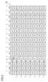
- FIG. 3is a diagram showing a well array image 70 displayed on the display section 3 by the first display section.
- the well array image 70is an image simulating the array of wells when viewed from the top of the actual multiple wells provided in the well plate 11 .
- well images 7 in which one well provided in the well plate 11 is associated with one well image 7are displayed corresponding to the actual array of wells.
- Each well image 7is an image simulating an actual well with a square image.
- Each well image 7shows a well symbol that can specify the position where the wells are arranged.
- Well symbolsare symbols such as A1, A2, . . . , H12 and X1A, X2A, .
- the touch position 8 currently touched by the operatoris indicated by a white arrow in order to facilitate the explanation of the position operated by the operator.
- a group of a total of 96 well images 7 of 8 rows on the right side of the well array image 70(rows indicated by “A” to “H” in the figure) ⁇ 12 columns (columns indicated by “1” to “12” in the figure). is a group of well images 7 corresponding to the first well called “96 wells” provided in the well plate 11 .
- a group of a total of 24 well images 7 of 8 rows (rows indicated by “A” to “H” in the drawing) ⁇ 3 columns (columns indicated by “X1” to “X3” in the drawing) on the left side of the well array image 70is a group of well images 7 corresponding to a second well called an “extra stand well” provided in the well plate 11 .
- the group of well images 7 of the first wellshows 96 types of well symbols from A1 to H12.
- the group of well images 7 of the second wellshows 24 types of well symbols X1A to X3H.
- all the well images 7can display the setting information (well information) of the sample to be injected into the corresponding well as an image (set image 77).
- a well image 7 with no well information setis displayed in response to the operator's finger touching and dragging operation on the display unit 3. After selecting the selected region, the finger is removed from the display unit 3 to release the touch state, thereby completing a series of drag operations. That is, the first menu image 721 is displayed. More specifically, when the operation detection unit of the touch panel 5 detects that a finger has been touched on the display unit 3 to perform a drag operation, the operation detection unit of the touch panel 5 transmits an operation detection signal to the control unit 4 . be done. Upon receiving such a drag operation detection signal, the control unit 4 performs control to display the first menu image 721 on the display unit 3 .
- FIG. 4is a diagram showing a well information setting method in the well image 7 of the first well displayed on the display unit 3.
- FIG. 4(A) to 4(D)show the display state of the well array image 70 that changes according to the operation.
- all the well images 7 shown in FIG. 3are actually displayed on the display unit 3, but due to the limited space in the drawing, the minimum number of well images 7 required for explanation is shown. It is shown.
- a drag operationsuch as The assumed drag operation is that the operator touches the display unit 3 with a finger and drags it in the direction indicated by an arrow 71 in the figure from the well image 7 of "A1" to the well image 7 of "C3", for example. This is an operation of selecting an area including the well image 7 corresponding to the well to be set by performing a drag operation.
- the well image 7 included within the range of the row and column where the drag operation was performed in the array of wellsis selected.
- the actual well corresponding to the well image 7 included within the range of the dragged row and columnis selected as the well information setting target.
- Such a drag operationis also called a well selection operation.
- the well image 7 selected by such a drag operationis not selected because the image is emphasized and displayed (hereinafter also referred to as "highlighted display"), as schematically shown by the thick line frame in the figure. It is notified so that it can be distinguished from the well image 7 .
- a first menu image 721showing options for three types of samples: "size standard”, “sample”, and "control”. is displayed on the right side with the position where the finger is released as the base point.
- a first option image 73indicating options for the "size standard” sample
- a second option image 74indicating options for the "sample” sample
- options for the "control” sampleare displayed.
- a third option image 75 shownis displayed.
- the first option image 73In the first option image 73, the second option image 74, and the third option image 75, an image of a container containing samples of different colors and an image indicating the type name of the sample are displayed.
- the first menu image 721may be displayed at any position as long as it is in the vicinity of the position where the drag operation has ended. By displaying the first menu image 721 in the vicinity of the position where the drag operation ends in this way, the first menu image 721 can be easily viewed after the drag operation ends.
- the first option image 73is displayed.
- 73 optionsare selected.
- the "size standard" sample corresponding to the first option image 73is selected according to the selection operation. data to be set as the sample to be injected into the well corresponding to the well image 7 selected as the well information setting target based on the drag operation of .
- the storage unit 9stores data for setting the type of sample corresponding to the selected option image as the sample to be injected into the well corresponding to the well image 7 selected as the well information setting target based on the drag operation described above. be.
- the operation of selecting by the operator touching any one of the first option image 73 to the third option image 75 while the first menu image 721 is displayedis also called an option selection operation. .
- FIG. 4(C)when the operator's touch operation on the first option image 73 is detected in a state where the first menu image 721 is displayed, as shown in FIG. 4(D), a single set image 77a consisting of a circular image having the same color as the image color of the sample in the operated option image is displayed as the set image 77 in the well image 7 selected as the well information setting target. Furthermore, as shown in FIG. 4(D), the highlighting of the selected well image 7 is canceled. As a result, in the selected well image 7, the type of set sample is shown by the image, so the operator can easily confirm which type of sample is set in which well.
- FIGS. 5 and 6are diagrams showing a method of deleting well information in the well image 7 of the first well displayed on the display unit 3.
- FIG. FIGS. 5(A) to 5(C) and FIGS. 6(D) to 6(F)show the display state of the well array image 70 that changes according to the operation.
- FIGS. 5 and 6all the well images 7 shown in FIG. 3 are actually displayed on the display unit 3, but due to the limited space of the drawings, the minimum number of well images necessary for explanation is shown.
- a well image 7is shown.
- the "size standard” sampleis In a state where the well array image 70 showing the set image 77 consisting of a single set image 77a indicating that the well information has been set, is displayed, in order to select the wells whose well information is to be deleted, , the case where the operator performs the following drag operation on the display unit 3 is assumed.
- An assumed drag operationis performed by an operator touching the display unit 3 with a finger and dragging the finger in the direction indicated by an arrow 71 in the figure from the well image 7 of "A2" to the well image 7 of "E5", for example. This is an operation of selecting an area including the well image 7 corresponding to the well to be deleted by performing a drag operation on the .
- the well image 7 included within the range of the row and column where the drag operation was performed in the array of wellsis selected.
- the actual well corresponding to the well image 7 including the well image 7 with well information set and the well image 7 with no well information set within the range of the dragged row and columnis selected. be done.
- the well image 7 selected by the drag operationis highlighted as indicated by a thick-line frame in the figure, so that it is notified so as to be distinguishable from the unselected well images 7 .
- a second menu image 722 showing a deletion option image 76 of "delete”is displayed on the right side with the position where the finger is released as the base point. be done.
- the deletion option image 76an image of a garbage container and an image showing the characters "delete" are displayed.
- the second menu image 722may be displayed at any position as long as it is in the vicinity of the position where the drag operation ends. By displaying the second menu image 722 in the vicinity of the position where the drag operation has ended in this way, the second menu image 722 can be easily viewed after the drag operation ends.
- the deletion confirmation image 80is displayed on the right side with the position where the finger is released as the base point.
- the deletion confirmation image 80includes a message image 81 confirming deletion of the sample information set in the well corresponding to the selected well image 7, and an OK image indicating an icon operated when the deletion is approved. 82 and a cancel image 83 indicating an icon operated when rejecting deletion are displayed.
- the well image 7 selected by the drag operationis an image corresponding to the first well
- the well image 7 for which the well information has already been setis moved to the first well corresponding to the well image 7 as described above.
- the followingis performed as follows. It may be possible to change the information of the sample selected by the second operation in such a manner that the information of the sample selected by the second operation is overwritten.
- the well image 7 selected by the drag operationis the image corresponding to the first well, for the well image 7 in which the well information has already been set, the first By displaying a menu image such as the menu image 721, it is possible to select a new type of sample.
- Well information addition setting method in well image 7 of the first wellNext, a method for additionally setting well information in the well image 7 of the first well will be described.
- One feature of the well information addition setting method described belowis that the well image 7 with no well information set is displayed in response to the operator touching and dragging the finger on the display unit 3. After the selected area is selected, the finger is removed from the display unit 3 to release the touch state, thereby ending the drag operation. 1 menu image 721 is displayed.
- FIG. 7is a diagram showing a well information addition setting method in the well image 7 of the first well displayed on the display unit 3.
- FIGS. 7A to 7Dshow the display state of the well array image 70 that changes according to the operation.
- all the well images 7 shown in FIG. 3are actually displayed on the display unit 3, but due to the limitation of the description of the drawing, the minimum number of well images 7 required for explanation is shown. It is shown.
- the "size standard” samplehas been set as the well information.
- the operatorperforms the following operations on the display unit 3 in order to select the wells to which the well information is to be additionally set. Assume the case of a drag operation.
- the assumed drag operationis that the operator touches the display unit 3 with a finger and drags the image between the well image 7 of "A2" in which the well information is unset, and the well image 7 of "C3", for example.
- the well image 7 within the range of the row and column where the drag operation was performedis selected.
- the actual well corresponding to the well image 7 within the range of the dragged row and columnis selected as the well information setting target.
- the well image 7 selected by the drag operationis reported by being highlighted as indicated by a thick line frame in the drawing.
- the second option image 74when the operator touches the second option image 74 while the first menu image 721 is displayed, and the touch operation is detected, the second option is displayed. Image 74 option is selected. As shown in FIG. 7(C), when an operation to select an option of the second option image 74 is performed, the sample of "sample" corresponding to the second option image 74 is selected according to the selection operation. Data to be set as the sample to be injected into the well corresponding to the well image 7 selected as the well information setting target based on the drag operation is stored in the storage unit 9 .
- the storage unit 9stores data for setting the type of sample corresponding to the selected option image as the sample to be injected into the well corresponding to the well image 7 selected as the well information setting target based on the drag operation described above. be.
- FIG. 7(C)when the first menu image 721 is displayed, for example, when the operator's touch operation on the second option image 74 is detected, as shown in FIG. 7(D), a single set image 77a consisting of a circular image having the same color as the image color of the sample in the touch-operated option image is displayed as the set image 77 in the well image 7 selected as the well information setting target. Furthermore, as shown in FIG. 7(D), the highlighting of the selected well image 7 is canceled. As a result, in the selected well image 7, the type of set sample is shown by the image, so the operator can easily confirm which type of sample is set in which well.
- Well information setting method in well image 7 of second wellNext, a method for setting well information in the well image 7 of the second well will be described.
- One feature of the well information setting method described belowis that a well image 7 with no well information set is displayed in response to the operator's finger touching and dragging operation on the display unit 3. After selecting the selected region, the finger is released from the display unit 3 to cancel the touch state, thereby ending the drag operation. That is, the menu image 721 is displayed.
- FIG. 8is a diagram showing a well information setting method in the well image 7 of the second well displayed on the display unit 3.
- FIG. FIGS. 8A to 8Dshow the display state of the well array image 70 that changes according to the operation.
- all the well images 7 shown in FIG. 3are actually displayed on the display unit 3, but due to the limitation of the description of the drawing, the minimum number of well images 7 required for explanation is shown. It is shown.
- a drag operationsuch as An assumed drag operation is performed by the operator touching the display unit 3 with a finger, and dragging the finger in the direction indicated by an arrow 71 in the figure from the well image 7 of "X1A" to the well image 7 of "B1", for example.
- Thisis an operation of selecting a region including the well image 7 corresponding to the well to be set by performing a drag operation on the .
- the well images 7 of the first and second wells included in the range of the row and column where the drag operation was performed in the array of wellsare selected. be.
- the actual wells corresponding to the well images 7 of the first and second wells within the range of the dragged row and columnare selected as well information setting targets.
- the well image 7 selected by such a drag operationis highlighted so as to be distinguishable from the unselected well image 7, as schematically shown by the thick-line frame in the figure. be.
- the first option image 73is displayed.
- 73 optionsare selected.
- the sample of "size standard" corresponding to the first option image 73is selected according to the selection operation. data to be set as the sample to be injected into the well corresponding to the well image 7 selected as the well information setting target based on the drag operation of .
- the touch operationis performed.
- the sample of the type corresponding to the selected option imageis set as the sample to be injected into the well corresponding to the well image 7 in the first and second wells selected as well information setting targets based on the drag operation described above.
- the data to be usedis stored in the storage unit 9 .
- FIG. 8(C)when the operator's touch operation on the first option image 73 is detected in a state where the first menu image 721 is displayed, as shown in FIG. 8(D), a single set image 77a consisting of a circular image of the same color as the image color of the sample in the touch-operated option image is displayed as the set image 77 in the well image 7 selected as the well information setting target. Furthermore, as shown in FIG. 8(D), the highlighting of the selected well image 7 is canceled. As a result, in the selected well image 7, the type of set sample is shown by the image, so the operator can easily confirm which type of sample is set in which well.
- Well information addition setting method in well image 7 of second wellNext, a method for additionally setting well information in the well image 7 of the second well will be described.
- One feature of the well information addition setting method described belowis that the well image 7 with no well information set is displayed in response to the operator touching and dragging the finger on the display unit 3. After selecting the selected region, the finger is removed from the display unit 3 to release the touch state, thereby ending the drag operation. is that the third menu image 723 showing the options of is displayed.
- FIG. 9is a diagram showing a method of setting multiple well information in the well image 7 of the second well displayed on the display unit 3.
- FIG. 9S. 9A to 9Dshow the display state of the well array image 70 that changes according to the operation.
- all the well images 7 shown in FIG. 3are actually displayed on the display unit 3, but due to the limited space in the drawing, the minimum number of well images 7 required for explanation is shown. It is shown.
- An assumed drag operationis performed by the operator touching the display unit 3 with a finger and dragging the finger in the direction indicated by an arrow 71 in the drawing from the well image 7 of "X1A” to the well image 7 of "X3C", for example.
- Thisis an operation of selecting a region including the well image 7 corresponding to the well to be set by performing a drag operation on the .
- the size standard sampleis set as the well information in each of the six well images 7 for which the well information has already been set.
- the well image 7 of the second well within the range of the row and column where the drag operation was performedis selected.
- the actual well corresponding to the well image 7 of the second well within the range of the dragged row and columnis selected as the well information setting target.
- the well image 7 selected by the drag operationis reported by highlighting the image as indicated by the thick frame in the figure.
- FIG. 9(A)After the drag operation shown in FIG. 9(A) is performed, when the operator releases the finger from the display unit 3 to release the touch state, the end of the drag operation is detected.
- a first option image 73, a second option image 74, a third option image 75, and a delete option image 76are displayed as shown in FIG. 9B.
- a third menu image 723is displayed. Note that the third menu image 723 may be displayed at any position as long as it is the position where the drag operation has ended. By displaying the third menu image 723 in the vicinity of the position where the drag operation ends in this way, the third menu image 723 can be easily viewed after the drag operation ends.
- the first option imageis displayed. 73 options are selected.
- the sample of "size standard" corresponding to the first option image 73is selected according to the selection operation.
- the data to be set as the sample to be injected into the wellis stored for wells for which well information has been set and wells for which well information has not been set, corresponding to the well image 7 selected as the well information setting target based on the drag operation of . stored in section 9.
- data additionally set as samples for multiple injectionsis stored in the storage unit 9 .
- data set as a sample for one-time injectionis stored in the storage unit 9 .
- the touch operationis performed.
- the type of sample corresponding to the selected option imageis set as the sample to be injected into the well corresponding to the well image 7 of the first and second wells selected as well information setting targets based on the drag operation described above.
- Datais additionally or newly stored in the storage unit 9 .
- the well imagelooks like this:
- the set image 77consisting of a single set image 77a indicates that the sample information for multiple injections has been set (hereinafter referred to as multiple set).
- the displaychanges to a multiple setting completed image 77b in which the two circular images shown are superimposed.
- the multiple set image 77bis displayed in a color different from the colors of the samples indicated by the first option image 73, the second option image 74, and the third option image 75.
- a set image 77consisting of a single set image 77a consisting of a circular image having the same color as the image color of the sample in the touch-operated option image is displayed. Furthermore, as shown in FIG. 9(D), the highlighting of the selected well image 7 is canceled.
- sample information for multiple injections for wells of the second wellSince the set image 77 changes from the single set image 77a to the multiple set image 77b in the well image 7, the operator can easily confirm in which well the sample information for multiple injections has been set. be able to.
- the setting of sample information for multiple injectionscan be set, for example, with the upper limit of sample information for injection of 120 times as the reference number of injections.
- the setting of sample information for multiple injectionsmay be such that only samples of the same type can be set in one well, or samples of different types can be set in one well.
- the setting of sample information for multiple injectionsmay be set for some of the selectable multiple types of samples, or may be set for all of the selectable multiple types of samples. may be
- the operation of setting sample information for multiple injections for the second wellselects only the well image 7 corresponding to the well in which the sample information for single injection is set based on the drag operation. It is also possible to perform based on The operation of setting sample information for multiple injections for the second well selects only the well image 7 corresponding to the well in which sample information for multiple injections has been set based on the drag operation. It is also possible to perform based on
- FIG. 10is a diagram showing a method of setting multiple well information in the well image 7 of the second well displayed on the display unit 3.
- FIGS. 10A to 10Dshow the display state of the well array image 70 that changes according to the operation.
- all the well images 7 shown in FIG. 3are actually displayed on the display unit 3, but due to the limited space in the drawing, the minimum number of well images 7 necessary for explanation is shown. It is shown.
- a state where the well image 7 of "X1C”, “X2C”, and "X3C” in which the sample is set as well informationis displayed in the second well in the well array image 70, the sample for multiple injections It is assumed that the operator performs the following drag operation on the display unit 3 in order to select a well for which information is to be set.
- the size standard sampleis set as the well information in each of the six well images 7 in which the well information is already set.
- the well image 7 of the second well included within the range of the row and column where the drag operation was performed in the array of wellsis selected.
- the actual well corresponding to the well image 7 of the second well included within the range of the dragged row and columnis selected as the well information setting target.
- the well image 7 selected by the drag operationis notified by highlighting the image, as schematically shown by the thick line frame in the figure.
- the first option imageis displayed.
- 73 optionsare selected.
- the "size standard" sample corresponding to the first option image 73is selected according to the selection operation. Data to be set as samples to be injected into wells for wells for which multiple well information has been set and wells for which well information has been set for a single well corresponding to the well image 7 selected as the well information setting target based on the drag operation of . is stored in the storage unit 9.
- data additionally set as samples for multiple injectionsis stored in the storage unit 9 .
- data set as a sample for one-time injectionis stored in the storage unit 9 .
- the touch operationis performed.
- the type of sample corresponding to the selected option imageis set as the sample to be injected into the well corresponding to the well image 7 of the first and second wells selected as well information setting targets based on the drag operation described above.
- Datais additionally or newly stored in the storage unit 9 .
- the well imagelooks like this: As for the well image 7 for which multiple well information has been set, a multiple set image 77 b is maintained as the set image 77 . As for the well image 7 in which the well information has been set for a single well, as shown in FIG. 10D, the set image 77 changes to a multiple set image 77b. Furthermore, as shown in FIG. 10(D), the highlighting of the selected well image 7 is canceled.
- Well information deletion method in well image 7 of second wellNext, a method for deleting well information in the well image 7 of the second well will be described.
- One feature of the well information deletion method described belowis that the well image 7 in which the well information has already been set and the well information are displayed in response to the operator touching and dragging the finger on the display unit 3 . After selecting the area where both the well image 7 where is not set is displayed, the finger is released from the display unit 3 to cancel the touch state, thereby ending the drag operation. 723 is displayed.
- FIGS. 11 and 12are diagrams showing a method of deleting well information in the well image 7 of the second well displayed on the display unit 3.
- FIG. FIGS. 11(A) to 11(C) and FIGS. 12(D) to 12(F)show the display state of the well array image 70 that changes according to the operation.
- FIGS. 11 and 12all the well images 7 shown in FIG. 3 are actually displayed on the display unit 3, but due to the limited space of the drawings, the minimum number of well images necessary for explanation is shown.
- a well image 7is shown.
- the well image 7 included within the range of the row and column where the drag operation was performed in the array of wellsis selected.
- the actual well corresponding to the well image 7 including the well image 7 with well information set and the well image 7 with no well information set, which is included in the range of the row and column where the drag operation is performedis displayed. selected.
- the well image 7 selected by such a drag operationis highlighted so as to be distinguishable from the unselected well image 7, as schematically shown by the thick-line frame in the figure. be.
- a deletion confirmation image 80is displayed on the right side with the position where the finger is released as a base point.
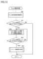
- FIG. 13is a flowchart showing well selection processing. Well selection processing is executed by the CPU 41 .
- the CPU 41executes the following processes in the well selection process.
- the well arrangement image 70is continuously displayed by step S (hereinafter abbreviated as S)0.
- S1based on the touch operation detection information from the operation detection unit of the touch panel 5, a well image 7 corresponding to the well to which the well information is to be set is displayed as shown in FIGS. Checks whether a drag operation to select a region containing is being performed by the operator.
- step S3it is determined whether or not the operator's finger has left the display unit 3 based on the detection information of the touch operation from the operation detection unit of the touch panel 5, so that it is the end of the above-described drag operation. Check whether or not
- the menu image display processingis processing for displaying menu images such as the first menu image 721, the second menu image 722, or the third menu image 723 shown in FIGS. be.
- FIG. 14is a flowchart showing menu image display processing.
- the menu image display processis executed by the CPU 41 .
- the CPU 41executes the following processes in the menu image display process. Through S41, it is confirmed whether or not the well selected by the drag operation described above includes the well of the second well. If it is determined that the well selected in S41 does not include the well of the second well, that is, if the selected well is only the first well, then in S42 the selected well is wells.
- S43returns to FIG. Display the first menu image 721 as shown, and return.
- the second menu image 722 as shown in FIG. 5is displayed in S44, and the process returns.
- S43returns to FIG. Display the first menu image 721 as shown, and return.
- the third menu image 723as shown in FIGS. 9 to 11 is displayed in S46, and the process returns.
- FIG. 15is a flowchart showing well information setting processing.
- the well information setting processis executed by the CPU 41 .
- the CPU 41executes the following processes in the well information setting process.
- step S51based on the touch operation detection information from the operation detection unit of the touch panel 5, selection operation of the option image for the menu image such as the first menu image 721, the second menu image 722, or the third menu image 723 is performed.
- the selection operationis a touch operation in which the operator selects the first option image 73, the second option image 74, the third option image 75, or the deletion option image 76.
- the processreturns. On the other hand, if it is determined in S51 that an option image selection operation for the menu image has been performed, it is determined in S52 whether or not the option image selection operation for the menu image is a deletion selection operation for selecting the deletion option image 76. to confirm.
- S52if it is determined that the selection operation of the option image for the menu image is not the deletion selection operation, that is, by selecting the first option image 73, the second option image 74, or the third option image 75, the well If it is determined that it is a sample selection operation for setting the sample to be injected into the sample, S53 corresponds to the well selected by the well selection process of FIG.
- the storage unit 9stores data for setting the information of the sample selected by the control as the sample to be injected into the selected well. This sets the well information for the selected well.
- the set image 77is displayed on the well image 7 corresponding to the well selected by the well selection process in FIG. 13, and the process returns.
- the well information indicating the set sample informationis the information indicating the sample for one injection, for example, a single set image of a color corresponding to the type of sample as shown in FIG. 77 a is displayed as the set image 77 .
- the well information indicating the set sample informationis the information indicating the sample for multiple injections, for example, a multiple set image 77b as shown in FIG. 9 is displayed.
- a deletion confirmation image 80 as shown in FIGS. 6 and 12is displayed in S55.
- S ⁇ b>56it is checked whether or not the operator has performed a deletion approval operation by touching the OK image 82 in the deletion confirmation image 80 . If it is confirmed in S56 that the deletion approval operation has been performed, in S57 the well information, which is the sample information stored in the storage unit 9, is deleted for the wells whose well information is to be deleted. Then, through S58, the displayed set image 77 is deleted as shown in FIGS. 6 and 12 for the well whose well information is to be deleted. Next, as shown in FIGS. 6 and 12, highlighting of the wells selected by the well selection process of FIG. 13 is terminated, and the process returns.
- the well information set using the tablet terminal 1is stored in the storage unit 9 of the tablet terminal 1 and sent from the tablet terminal 1 to the sample injection device 10 when the sample injection device 10 injects the sample.
- the well information set using the tablet terminal 1may be sent to the storage device provided in the sample injection device 10 each time it is stored in the storage section 9 of the tablet terminal 1 . Transmission of such well information is the same in each of the following embodiments.
- the sample injection device 10performs an operation of injecting a sample set for each well into each well based on well information set using the tablet terminal 1 .
- the option image for the menu imageis displayed. If it is determined that the selection operation is not the delete selection operation, it is determined whether or not the first well information overwriting process is being executed. If it is determined that the first well information overwriting process is being executed, the setting The process of S53A (not shown) may be performed to overwrite the already-existed well information with the newly selected sample information.
- the option image displayed inmay be one image.
- the option image displayed in the menu imageshould be at least one image.
- the drag operationwhich is the first operation, is performed by selecting an area including the well image 7 to be set, and displaying the second image showing the information of the sample that can be set in the well corresponding to the well image 7 by a menu. Since it also serves as an operation, it is possible to simplify the operation when setting samples to be injected into the wells of the well plate.
- the well plate 11can be shared by a plurality of users, and when the second user sets the well information for the wells for which the well information has already been set by the first user, A well information setting method for displaying a well image in a display mode indicating that well information cannot be set for the well will be described.
- login informationis given to each user, and when each user logs into the tablet terminal 1, the user is assigned based on the login information. It should be possible to identify it.
- FIG. 16is a diagram showing a well array image 70 displayed on the display section 3 according to the second embodiment.
- the well array image 70 of FIG. 16differs from the well array image 70 of FIG. 3 in that an unusable well image 78 is displayed as the well image.
- the disabled well image 78is displayed as follows. For example, during the execution of an analysis on an analysis schedule using an analyzer, the display is based on well information that was stored prior to pausing.
- the unusable well image 78is displayed by the second user when the well information has already been set by the first user. When setting, it is displayed to indicate that the well is an unusable well so that the second user cannot set the well information.
- the second embodimentmainly different parts from the first embodiment will be explained.
- the unusable well image 78does not show a well symbol, has a lower image density than the well image 7, and has diagonal lines, etc., to remind us that the unusable well is an unusable well. It is displayed in the display mode.
- the unusable well image 78 as described aboveis displayed as follows. For example, during the execution of analysis targeting the wells of the well sheet in the analysis schedule using the analyzer, the unusable well image 78 is displayed based on the well information stored before pausing. Specifically, the disabled well image 78 is displayed as follows. Analysis is performed by the analyzer according to the analysis schedule. Then pause the analysis. When the well information of the well sheet to be analyzed is edited during the pause, wells whose well information was stored before the pause are displayed as unusable well images 78 . Also, when adding a well sheet to be analyzed, the wells whose well information was stored before the suspension is displayed as the unusable well image 78 .
- One feature of the well information setting method described belowis that a well image 7 with no well information set is displayed in response to the operator's finger touching and dragging operation on the display unit 3. After selecting the selected region, the finger is released from the display unit 3 to cancel the touch state, thereby ending the drag operation. That is, the menu image 721 is displayed.
- FIGS. 17 and 18are diagrams showing a well information setting method for the well image 7 in the first and second wells displayed on the display unit 3.
- FIG. 17 and 18show the display state of the well array image 70 that changes according to the operation.
- FIGS. 17 and 18all the well images 7 and unusable well images 78 shown in FIG. 16 are actually displayed on the display unit 3.
- a minimum number of well images 7 and disabled well images 78are shown.
- FIG. 17Ain a state in which a well array image 70 showing a well image 7 in which well information is not set and an unusable well image 78 is displayed, first well and second well information It is assumed that the operator performs the following drag operation on the display unit 3 in order to select a well for which well information is to be set.
- an assumed drag operationis performed by the operator touching the display unit 3 with a finger, for example, dragging the unusable well image 78 of "X1A" to the unusable well image 78 of "E1".
- By performing a drag operation in the direction indicated by an arrow 71 in the figure between andthe area including the well image 7 corresponding to the well for which information is to be set in the first well and the second well is selected. .
- the well image 7 included within the range of the row and column where the drag operation was performed in the array of wellsis selected.
- Disabled well images 78 contained within the range of the dragged row and columnare not selected.
- the actual well corresponding to the well image 7 within the range of the dragged row and columnis selected as the well information setting target.
- Such a drag operationis also called a well selection operation.
- the well image 7 selected by such a drag operationis displayed in a highlighted manner as shown by a thick-line frame in the drawing, so that it can be distinguished from the unselected well image 7. .
- the first option image 73is displayed.
- 73 optionsare selected.
- the sample of "size standard" corresponding to the first option image 73is selected according to the selection operation. data to be set as the sample to be injected into the well corresponding to the well image 7 selected as the well information setting target based on the drag operation of .
- the storage unit 9stores data for setting the type of sample corresponding to the selected option image as the sample to be injected into the well corresponding to the well image 7 selected as the well information setting target based on the drag operation described above. be.
- the sample of the touch-operated option imageis displayed. is displayed as a set image 77 in the well image 7 selected as the well information setting target. Furthermore, as shown in FIG. 18(E), the highlighting of the selected well image 7 is canceled. As a result, in the selected well image 7, the type of set sample is shown by the image, so the operator can easily confirm which type of sample is set in which well.
- the unusable well image 78even if it exists in the specified range of the drag operation, it is not selected as an object for which well information is set, nor is well information set. This suppresses the possibility that the user will change the well information of the wells for which well information has been set.
- Well information deletion method in well image 7 of second wellNext, a method for deleting well information in the well image 7 of the second well will be described.
- One feature of the well information deletion method described belowis that the well image 7 in which the well information has already been set and the well information are displayed in response to the operator touching and dragging the finger on the display unit 3 . After selecting the area where both the well image 7 where is not set is displayed, the finger is released from the display unit 3 to cancel the touch state, thereby ending the drag operation. 723 is displayed.
- FIGS. 19(A), (B), FIGS. 20(C), (D), and FIGS. 21(E), (F)show the display state of the well array image 70 that changes according to the operation. ing.
- FIGS. 19 to 21all the well images 7 shown in FIG. 16 are actually displayed on the display unit 3, but the minimum number of well images necessary for explanation is required due to the limited space of the drawings. A well image 7 is shown.
- a single set image 77aindicating that well information has been set
- the operatoroperates the display unit 3 to select the wells whose well information is to be deleted.
- a drag operationsuch as An assumed drag operation is performed by the operator touching the display unit 3 with a finger and dragging the finger in the direction indicated by an arrow 71 in the figure from the well image 7 of "X1A” to the well image 7 of "G2", for example. This is an operation of selecting an area including the well image 7 corresponding to the well to be deleted by performing a drag operation on the .
- the well image 7 included within the range of the row and column where the drag operation was performed in the array of wellsis selected.
- the actual well corresponding tois selected.
- the well image 7 selected by the drag operationis displayed in an emphasized manner as indicated by the thick frame in the figure, and is reported so as to be distinguishable from the unselected well images 7.
- a deletion confirmation image 80is displayed on the right side with the position where the finger is released as a base point.
- the well information setting method shown in the second embodimentcan be realized by executing the same processes as those executed by the control unit 4 shown in FIGS. 13 to 15 of the first embodiment.
- the well array image 70 as shown in FIG. 16will be displayed in the processing of S0 in FIG.
- the display of changing the well image 7 to the unusable well image 78is executed by confirming the well information set by another user each time the user changes.
- FIG. 21(E)when the operator touches the OK image 82 while the deletion confirmation image 80 is being displayed, and the touch operation is detected, a selection is made according to the touch operation.
- the well information stored in the storage unit 9 for the well corresponding to the well image 7 in which the well information has already been setis deleted.
- Such an operation of touching the OK image 82is also called a deletion confirmation operation.
- FIG. 21(F)among the selected well images 7, in the well image 7 corresponding to the well from which the well information has been deleted, a single set The set image 77 consisting of the image 77a or a plurality of set images 77b is deleted and the well symbol is displayed.
- the highlighting displayed in the selected well image 7is canceled. This allows the operator to easily confirm the well image 7 corresponding to the well from which the well information has been deleted.
- the drag operationwhich is the first operation, is performed by selecting an area including the well image 7 to be set, and displaying the second image showing the information of the sample that can be set in the well corresponding to the well image 7 by a menu. Since it also serves as an operation, it is possible to simplify the operation when setting samples to be injected into the wells of the well plate.
- the unusable well image 78even if it exists in the specified range of the drag operation, it is not selected as a deletion target of the well information.
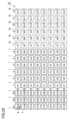
- FIG. 22is a diagram showing a well array image 70 displayed on the display section 3 according to the third embodiment.
- the well array image 70 in FIG. 22differs from the well array image 70 in FIG. 3 in that a diluted well image 79 is displayed as the well image.
- the wells in the 1st to 6th columnsare wells into which samples of a standard concentration are injected, and the wells in the 7th to 12th columns are wells into which samples diluted from the standard concentration are injected. is.
- a sample obtained by diluting the same sample as the sample injected into each of the wells in the first rowis injected into each of the dilution wells in the seventh row.
- a sample obtained by diluting the same sample as the sample to be injected into each well of the second rowis injected into each of the dilution wells of the eighth row.
- a sample obtained by diluting the same sample as the sample to be injected into each well of the third rowis injected into each of the dilution wells of the ninth row.
- a sample obtained by diluting the same sample as the sample to be injected into each of the wells in the fourth rowis injected into each of the dilution wells in the tenth row.
- a sample obtained by diluting the same sample as the sample to be injected into each well of the fifth rowis injected into each of the dilution wells of the 11th row.
- a sample obtained by diluting the same sample as the sample to be injected into each well of the sixth rowis injected into each of the dilution wells of the 12th row.
- the well array image 70 in FIG. 22differs from the well array image 70 in FIG. 3 in that the wells in the 7th to 12th columns are displayed as dilution well images 79 indicating dilution wells.
- the diluted well image 79has a lower image density than the well image 7, and a triangular image is shown in part of the image to indicate that it is a diluted well image.
- Well information setting method in well image 7 of first wellNext, a method for setting well information in the well image 7 of the first well will be described.
- One feature of the well information setting method described belowis that a well image 7 with no well information set is displayed in response to the operator's finger touching and dragging operation on the display unit 3. After selecting the selected region, the finger is released from the display unit 3 to cancel the touch state, thereby ending the drag operation. That is, the menu image 721 is displayed.
- FIGS. 23 and 24are diagrams showing a well information setting method in the well image 7 of the first well displayed on the display unit 3.
- FIG. 23 and 24show the display state of the well array image 70 that changes according to the operation.
- FIGS. 23 and 24all well images 7 and diluted well images 79 shown in FIG. 22 are actually displayed on the display unit 3. A minimal number of well images 7 and diluted well images 79 are shown.
- the operatorin a state where well information is not set for all first wells, the operator operates the display unit 3 as follows in order to select a well for which well information is to be set. Assume that a drag operation such as An assumed drag operation is performed by the operator touching the display unit 3 with a finger and dragging the finger in the direction indicated by an arrow 71 in the drawing from the well image 7 of "A1" to the well image 7 of "C6", for example. This is an operation of selecting a region including the well image 7 corresponding to the well to be set by performing a drag operation on the .
- a drag operationsuch as An assumed drag operation is performed by the operator touching the display unit 3 with a finger and dragging the finger in the direction indicated by an arrow 71 in the drawing from the well image 7 of "A1" to the well image 7 of "C6", for example.
- Thisis an operation of selecting a region including the well image 7 corresponding to the well to be set by performing a drag operation on the .
- the well image 7 included within the range of the row and column where the drag operation was performed in the array of wellsis selected.
- the actual well corresponding to the well image 7 within the range of the dragged row and columnis selected as the well information setting target.
- the well image 7 selected by the drag operationis highlighted so as to be distinguished from the unselected well image 7 by highlighting the image as shown by a thick frame in the drawing.
- a fourth menu image 724displaying a first option image 73, a second option image 74, and a third option image 75 is displayed. is displayed.
- the fourth menu image 724indicates that the first option image 73 cannot be selected as an option by displaying the first option image 73 in a darker image than the other option images. It should be noted that the fourth menu image 724 may be displayed at any position as long as it is near the position where the drag operation ends. By displaying the fourth menu image 724 in the vicinity of the position where the drag operation has ended in this way, the fourth menu image 724 can be easily viewed after the drag operation ends.
- the second option image 74when the operator touches the second option image 74 while the fourth menu image 724 is being displayed, and the touch operation is detected, the second option is displayed. Image 74 option is selected.
- the specimen of "sample" corresponding to the second option image 74is selected according to the operation of selection. to the sample to be injected into the well corresponding to the well image 7 selected as the well information setting target based on the drag operation of , and to the dilution well corresponding to the selected well image 7 and the dilution well image 79 corresponding to the selected well image 7.
- Data set as a sample to be injectedis stored in the storage unit 9 .
- the touch-operated optionis displayed.
- a sample of the type corresponding to the imageis injected into the well corresponding to the well image 7 selected as the well information setting target based on the drag operation described above and the dilution well corresponding to the selected well image 7. is stored in the storage unit 9.
- a single set image 77aconsisting of a circular image having the same color as the image color of the sample in the touch-operated option image is displayed as the set image 77 in the well image 7 selected as the well information setting target.
- a single set image 77aconsisting of a circular image having the same color as the image color of the sample in the touch-operated option image is the well image 7 selected as the well information setting target. is displayed as a set image 77 in the diluted well image 79 corresponding to the .
- the color of the single set image 77 a displayed as the set image 77 in the diluted well image 79is displayed in a color with a lower density than the color of the set image 77 displayed in the well image 7 . Furthermore, as shown in FIG. 24(D), the highlighted display of the selected well image 7 is canceled.
- the well information setting method shown in the third embodimentcan be realized by executing the same processes as those executed by the control unit 4 shown in FIGS. 13 to 15 of the first embodiment. In that case, the well array image 70 as shown in FIG. 22 will be displayed in the processing of S0 in FIG.
- a set image 77which is a single set image 77a consisting of a circular image having the same color as the image color of the sample in the operated option image, is set as the well information setting target based on the drag operation described above.
- the selected well image 7 and the diluted well image 79 corresponding to the well image 7are displayed.
- the highlighted display of the selected well image 7is canceled.
- the type of sample set in the selected well image 7 and the type of sample set in the corresponding diluted well image 79are displayed by image, so that the operator can determine which type of well in which well. It can be easily checked whether the sample has been set.
- the drag operationserves both as an operation for selecting an area including the well image 7 to be set and as an operation for displaying the second image showing the information of the sample that can be set in the well corresponding to the well image 7 by a menu
- the well plateThe operation in setting the sample to be injected into the well can be simplified.
- the dilution well image 79is automatically assigned as the well image. can be simplified.
- Communication between the tablet terminal 1 and the sample injection device 10may be performed by either wireless communication or wired communication.
- the sample information setting method for setting the sample information according to the operator's operation in the injection device for injecting the sample into each of the plurality of wells provided in the well plate as described aboveis a liquid crystal display that is not a touch panel type.
- Various images as described abovemay be displayed on a display device such as a device, and the operations may be executed based on the operator's operation of an operating device such as a mouse.
- the set image 77 shown in the well image 7may indicate the type of sample that has been set using an image that indicates only color, only shape, or a combination of color and shape.
- the well symbolmay be displayed without displaying, or may be displayed with the well symbol.
- a display indicating that the deletion option image 76 cannot be selectedis displayed, and a first option image 73, a second option image 74, and a third option image 75 are displayed.
- a display indicating that these images cannot be selectedmay be displayed.
- the multiple set image 77bmay be displayed in a display mode in which the type of sample set to be injected multiple times is specified by color or the like. .
- the image of the input field for displaying the commentis displayed, and the sample information set by the operator is displayed. You may enable it to input comment texts, such as a comment. In this case, the comment can be input for information that cannot be expressed only by the sample name to be set, such as the experimental conditions.
- the well information set using the tablet terminal 1may be stored in the storage section 9 of the tablet terminal 1 as well as in the storage section provided in the sample injection device 10 .
- the well information set using the tablet terminal 1may be stored in the storage section 9 of the tablet terminal 1 as well as in the storage section provided in the sample injection device 10 .
- the well information set using the tablet terminal 1is stored only in the storage unit 9 of the tablet terminal 1, and is sent from the tablet terminal 1 to the sample injection device 10 when the sample is injected by the sample injection device 10. may be made available.
- the display that emphasizes the well image such as the well image 7may be realized by making the display color of the well image to be emphasized darker than the reference concentration, and the shape of the well image to be emphasized is different from the reference shape. It may be realized by using a shape.
- the color of the well imagemay be made different to clarify the difference between the well types, and the shape of the well image may be made different. By doing so, a display may be made to clarify the difference between the types of wells.
- the unusable well image 78may be made visually distinguishable from the usable well image 7 by making the image color density lighter than the well image 7, and has a different shape from the well image 7. , it may be visually distinguishable from the usable well image 7 .
- the diluted well image 79may be visually distinguishable from the usable well image 7 by making the image color density lighter than the well image 7, and may have a different shape from the well image 7. may be made visually distinguishable from the usable well image 7.
- an image showing the well information setting results using the well image 7 of the well array image 70 as described above in a table formatis displayed on the same screen where the well array image 70 is displayed. It may be displayed above. By doing so, it is possible to confirm the setting state of the well information in both the well array image 70 and the tabular image.
- a sample information setting method for setting sample information according to an operator's operation in an injection device that injects a sample into each of a plurality of wells provided in a well plateis an injection device that injects a sample into each of a plurality of vials in a vial rack. It may be applied to a sample information setting method for setting according to an operation.
- a vial rackis a rack capable of arranging a plurality of containers to be injected, such as vials, and is used, for example, in autosamplers such as liquid chromatographs and gas chromatographs.
- the above-described embodimentmay be a sample information setting method for setting sample information according to an operator's operation in an injection device that injects a sample into each of a plurality of injection targets.
- a sample information setting method for setting sample information according to an operator's operation in an injection devicefor injecting a sample into each of a plurality of injection targets (wells), wherein a step (S0) of displaying a plurality of first images (well images 7) respectively corresponding to objects (wells);
- the array(well array image 70)
- the first image included in the areais displayed.
- a menushowing at least one sample information (first option image 73, second option image 74, third option image 75) that can be set as an injection target (well) corresponding to one image (well image 7).
- the first operationwhen the first operation of selecting the region including the first image to be set by the drag operation is completed, , by displaying a second image showing, in a menu, information about at least one sample that can be set as an injection target corresponding to the first image included in the region, the first operation performs the setting target first image. Since the selection operation of the region to be included and the display operation of the second image showing the information of the sample that can be set as the injection target corresponding to the first image by the menu, the sample to be injected into a plurality of injection targets is set. operation can be simplified.
- information on the sample that can be set as an injection target corresponding to the first image included in the region selected by the first operationis shown in the menu by the second image, and information on the sample included in the second image is displayed on the second image.
- the sample informationis information on the types of samples to be injected into each of a plurality of injection targets (sample types such as "size standard”, “sample”, and “control”). According to such a configuration, the sample information is information about the type of the sample to be injected into each of the plurality of injection targets, thereby simplifying the operation of setting the type of the sample to be injected into the plurality of injection targets. can be done.
- the second image(first menu image 721, third menu image 723) is displayed near the position where the first operation ends. According to such a configuration, the second image is displayed in the vicinity of the position where the first operation has ended, so it becomes easier to visually recognize the second image after the first operation ends.
- the first image (well image 7) and the second image (first menu image 721, third menu image 723)are displayed on the display device (touch panel display unit or non-touch panel display device).
- the first operationends in response to the end of a series of operations (end of a series of drag operations) when a drag operation (operation with a finger or an operation device such as a mouse) is performed. .
- the first operationends in response to the end of the series of operations when the drag operation is performed, so the second image ( When the first menu image 721 and the third menu image 723) are displayed, the second image can be displayed without further performing an operation other than the first operation, thereby simplifying the operator's operation. be able to.
- the first image included in the areais displayed in a different display mode according to the sample selected by the second operation, so that the information of the sample set as the injection target can be visually displayed. can be easily verified.
- the sample information that has already been setis deleted. can be deleted.
- the methodfurther includes a step (S54) of displaying the first image in different modes (the display mode of the single-set image 77a and the display mode of the multiple-set image 77b are different) according to the number of sample injections.
- the first imageis displayed in different modes according to the set number of injections, so that the set number of injections can be visually confirmed easily.
- the plurality of injection targetsincludes a first injection target (first well) and a second injection target (second well).
- information on the sample to be injectedcan be set for multiple injections. 1 well), changing the already set sample information by overwriting it with the sample information selected by the second operation (not shown) S44A, S53A), and when setting the information of the sample to be injected for the second injection target, the step of adding the information of the sample selected by the second operation to the already set information of the sample (S53). ).
- the already set information of the sampleis overwritten with the information of the sample selected by the second operation. Since the information is changed, the type of sample to be set can be easily changed for the first injection target for which sample information has already been set.
- Multiple injection targets (wells)can be shared by multiple users, including the first user and the second user, and when the first user sets sample information, It further comprises a step (S0 used in the second embodiment) of indicating that the first image in which the sample information has been set by the second user cannot be set (displaying the unusable well image 78).
- the plurality of injection targetsare a plurality of wells (first well, second well) provided on a well plate (well plate 11). With such a configuration, it is possible to simplify the operation when setting samples to be injected into a plurality of wells.
- sample information setting program of the present disclosurehas the following features. (11) Sample information setting for causing a computer to execute a process of setting sample information according to an operator's operation in an injection device (sample injection device 10) for injecting a sample into each of a plurality of injection targets (wells).
- a programcomprising a step (S0) of displaying a plurality of first images (well images 7) respectively corresponding to a plurality of injection targets (wells);
- the first operationdrag operation
- the drag operationof selecting the region including the first image (well image 7) to be set by the drag operation in the array (well array image 70) of a plurality of injection targets (wells)
- at least one sample information(first option image 73, second option image 74, third option a step (S4) of displaying a second image (first menu image 721, third menu image 723) showing the image 75) as a menu; set the information of the sample selected by the second operation (option selection operation) from the information of at least one sample that is included in the injection target (well) corresponding to the first image (well image 7) included in the region and the step (S53) to be executed.
- the first operationwhen the first operation of selecting the region including the first image to be set by the drag operation is completed, , by displaying a second image showing, in a menu, information about at least one sample that can be set as an injection target corresponding to the first image included in the region, the first operation performs the setting target first image. Since the selection operation of the containing area and the display operation of the second image showing the information of the sample that can be set as the injection target corresponding to the first image by the menu, the sample to be injected into a plurality of injection target wells is set.
- the plurality of injection targetsare a plurality of wells (first well, second well) provided on a well plate (well plate 11). With such a configuration, it is possible to simplify the operation when setting samples to be injected into a plurality of wells.
- sample information setting device of the present disclosurehas the following features. (13) A well information setting device (tablet terminal 1) for setting sample information according to an operator's operation in an injection device (sample injection device 10) for injecting a sample into each of a plurality of injection targets (wells). and a display unit (display unit 3), a control unit (control unit 4), and a storage unit (storage unit 9).
- the first image (well image)A second image that displays on the display unit a second image (first menu image 721, third menu image 723) showing information of at least one sample that can be set as an injection target (well) corresponding to 7) in a menu.
- a setting process (S53) for storing data to be set for the injection target (well) corresponding to the first image (well image 7) included in the region in the storage unitis executed.
- the first operationwhen the first operation of selecting the region including the first image to be set by the drag operation is completed, , by displaying a second image showing, in a menu, information about at least one sample that can be set as an injection target corresponding to the first image included in the region, the first operation performs the setting target first image. Since the selection operation of the region to be included and the display operation of the second image showing the information of the sample that can be set as the injection target corresponding to the first image by the menu, the sample to be injected into a plurality of injection targets is set. operation can be simplified.
- information on the sample that can be set as an injection target corresponding to the first image included in the region selected by the first operationis shown in the menu by the second image, and information on the sample included in the second image is displayed on the second image.
- the plurality of injection targetsare a plurality of wells (first well, second well) provided on a well plate (well plate 11). With such a configuration, it is possible to simplify the operation when setting samples to be injected into a plurality of wells.
Landscapes
- Engineering & Computer Science (AREA)
- General Engineering & Computer Science (AREA)
- Theoretical Computer Science (AREA)
- Health & Medical Sciences (AREA)
- Physics & Mathematics (AREA)
- General Physics & Mathematics (AREA)
- General Health & Medical Sciences (AREA)
- Chemical & Material Sciences (AREA)
- Human Computer Interaction (AREA)
- Analytical Chemistry (AREA)
- Immunology (AREA)
- Biochemistry (AREA)
- Life Sciences & Earth Sciences (AREA)
- Pathology (AREA)
- Biomedical Technology (AREA)
- Chemical Kinetics & Catalysis (AREA)
- Clinical Laboratory Science (AREA)
- Epidemiology (AREA)
- Medical Informatics (AREA)
- Primary Health Care (AREA)
- Public Health (AREA)
- Hematology (AREA)
- Business, Economics & Management (AREA)
- General Business, Economics & Management (AREA)
- Microscoopes, Condenser (AREA)
- Automatic Analysis And Handling Materials Therefor (AREA)
Abstract
Description
Translated fromJapanese本発明は、試料情報設定方法、試料情報設定プログラム、および、試料情報設定装置に関する。The present invention relates to a sample information setting method, a sample information setting program, and a sample information setting device.
化学的検査および生物学的分析等の各種の検査および分析では、例えばウェルプレートに設けられた複数のウェル等の複数の注入対象のそれぞれに試料を注入する試料注入装置が用いられる。試料注入装置においてどのような試料を注入させるかの設定は、たとえば、注入する試料の情報を設定するためのソフトウェアによって行うことが可能である。In various tests and analyses, such as chemical tests and biological analyses, a sample injection device is used that injects a sample into each of a plurality of injection targets, such as a plurality of wells provided on a well plate. The setting of what kind of sample is to be injected in the sample injection device can be performed, for example, by software for setting information on the sample to be injected.
たとえば、複数の注入対象に注入する試料の情報を設定する方法としては、ウェル配置に対応するセル配置を有するテンプレート画像を作成して表示部に表示し、分析担当者が直接的な文字入力、および、事前に作成したサンプルリストからのドラッグ&ドロップ操作により、各セルに情報を入力する方法が考えられている(特許文献1)。For example, as a method of setting the information of the sample to be injected into a plurality of injection targets, a template image having a cell arrangement corresponding to the well arrangement is created and displayed on the display unit, and the person in charge of analysis directly inputs characters, Also, a method of inputting information into each cell by a drag-and-drop operation from a pre-created sample list has been considered (Patent Document 1).
しかし、特許文献1のような従来の試料情報の設定方法では、直接的な文字入力操作、および、事前に作成したサンプルリストからのドラッグ&ドロップ操作等の操作が煩雑であるという問題があった。However, in the conventional sample information setting method as disclosed in
本発明の目的は、複数の注入対象に注入する試料を設定する場合における操作を簡素化することである。An object of the present invention is to simplify the operation when setting samples to be injected into a plurality of injection targets.
本開示のある局面に従うと、試料情報設定方法は、複数の注入対象のそれぞれに試料を注入する注入装置において試料の情報を操作者の操作に応じて設定する試料情報設定方法であって、複数の注入対象のそれぞれに対応する複数の第1画像を表示するステップと、複数の第1画像により表示された複数の注入対象の配列において、設定対象の第1画像を含む領域をドラッグ操作により選択する第1操作が終了したことに応じて、当該領域に含まれる第1画像に対応する注入対象に設定可能となる少なくとも1つの試料の情報をメニューで示す第2画像を表示するステップと、第2画像に含まれる少なくとも1つの試料の情報から第2操作によって選択された試料の情報を、領域内に含まれる第1画像に対応する注入対象に対して設定するステップとを備える。According to one aspect of the present disclosure, a sample information setting method is a sample information setting method for setting sample information according to an operator's operation in an injection device that injects a sample into each of a plurality of injection targets, the sample information setting method comprising: a step of displaying a plurality of first images corresponding to each of the injection targets; and selecting a region including the first image to be set in the array of the plurality of injection targets displayed by the plurality of first images by a drag operation. displaying a second image showing, in a menu, information about at least one sample that can be set as an injection target corresponding to the first image included in the region in response to the completion of the first operation; and setting the information of the sample selected by the second operation from the information of at least one sample included in the two images to the injection target corresponding to the first image included in the region.
本開示の他の局面に従うと、試料情報設定プログラムは、複数の注入対象のそれぞれに試料を注入する注入装置において試料の情報を操作者の操作に応じて設定する処理をコンピュータに実行させるための試料情報設定プログラムであって、複数の注入対象のそれぞれに対応する複数の第1画像を表示するステップと、複数の第1画像により表示された複数の注入対象の配列において、設定対象の第1画像を含む領域をドラッグ操作により選択する第1操作が終了したことに応じて、当該領域に含まれる第1画像に対応する注入対象に設定可能となる少なくとも1つの試料の情報をメニューで示す第2画像を表示するステップと、第2画像に含まれる少なくとも1つの試料の情報から第2操作によって選択された試料の情報を、領域内に含まれる第1画像に対応する注入対象に対して設定するステップとを実行させる。According to another aspect of the present disclosure, a sample information setting program causes a computer to execute processing for setting sample information in an injection device that injects a sample into each of a plurality of injection targets in accordance with an operator's operation. A sample information setting program comprising: a step of displaying a plurality of first images respectively corresponding to a plurality of injection targets; A second menu showing information of at least one sample that can be set as an injection target corresponding to the first image included in the area in response to the completion of the first operation of selecting the area including the image by the drag operation. displaying two images; and setting information of a sample selected by a second operation from information of at least one sample included in the second image to an injection target corresponding to the first image included in the region. to perform the steps to be performed.
本開示の他の局面に従うと、試料情報設定装置は、複数の注入対象のそれぞれに試料を注入する注入装置において試料の情報を操作者の操作に応じて設定する試料情報設定装置であって、表示部と、制御部と、記憶部とを備え、制御部は、複数の注入対象のそれぞれに対応する複数の第1画像を表示部に表示する第1画像表示処理と、複数の第1画像により表示された複数の注入対象の配列において、設定対象の第1画像を含む領域をドラッグ操作により選択する第1操作が終了したことに応じて、当該領域に含まれる第1画像に対応する注入対象に設定可能となる少なくとも1つの試料の情報をメニューで示す第2画像を表示部に表示する第2画像表示処理と、第2画像に含まれる少なくとも1つの試料の情報から第2操作によって選択された試料の情報を、領域内に含まれる第1画像に対応する注入対象に対して設定するデータを記憶部に記憶させる設定処理とを実行する。According to another aspect of the present disclosure, a sample information setting device is a sample information setting device that sets sample information according to an operator's operation in an injection device that injects a sample into each of a plurality of injection targets, A display unit, a control unit, and a storage unit, wherein the control unit performs first image display processing for displaying a plurality of first images corresponding to each of a plurality of injection targets on the display unit; In the array of the plurality of injection targets displayed by , in response to the completion of the first operation of selecting the region including the first image to be set by the drag operation, the injection corresponding to the first image included in the region second image display processing for displaying on the display unit a second image showing information on at least one sample that can be set as a target in a menu; and selecting from information on at least one sample included in the second image by a second operation. and a setting process for storing data for setting the obtained sample information to the injection target corresponding to the first image included in the region in the storage unit.
本開示のある局面に従うと、複数の第1画像により表示された複数の注入対象の配列において、設定対象の第1画像を含む領域をドラッグ操作により選択する第1操作が終了したことに応じて、当該領域に含まれる第1画像に対応する注入対象に設定可能となる少なくとも1つの試料の情報をメニューで示す第2画像を表示することにより、第1操作が、設定対象の第1画像を含む領域の選択操作と、第1画像に対応する注入対象に設定可能となる試料の情報をメニューで示す第2画像の表示操作とを兼ねるので、複数の注入対象に注入する試料を設定する場合における操作を簡素化することができる。また、第1操作により選択された領域に含まれる第1画像に対応する注入対象に設定可能となる試料の情報を第2画像によりメニューで示し、第2画像に含まれる試料の情報から第2操作によって選択された試料の情報を、領域内に含まれる第1画像に対応する注入対象に対して設定することにより、複数の注入対象に同じ設定を行う作業を容易化することができる。According to one aspect of the present disclosure, in the array of the plurality of injection targets displayed by the plurality of first images, in response to the completion of the first operation of selecting the region including the first image to be set by the drag operation. , by displaying a second image showing, in a menu, information about at least one sample that can be set as an injection target corresponding to the first image included in the region, the first operation performs the setting target first image. Since the selection operation of the region to be included and the display operation of the second image showing the information of the sample that can be set as the injection target corresponding to the first image by the menu, the sample to be injected into a plurality of injection targets is set. operation can be simplified. In addition, information on the sample that can be set as an injection target corresponding to the first image included in the region selected by the first operation is shown in the menu by the second image, and information on the sample included in the second image is displayed on the second image. By setting the information of the sample selected by the operation for the injection target corresponding to the first image included in the region, it is possible to facilitate the work of performing the same setting for a plurality of injection targets.
本開示の他の局面に従うと、複数の第1画像により表示された複数の注入対象の配列において、設定対象の第1画像を含む領域をドラッグ操作により選択する第1操作が終了したことに応じて、当該領域に含まれる第1画像に対応する注入対象に設定可能となる少なくとも1つの試料の情報をメニューで示す第2画像を表示することにより、第1操作が、設定対象の第1画像を含む領域の選択操作と、第1画像に対応する注入対象に設定可能となる試料の情報をメニューで示す第2画像の表示操作とを兼ねるので、複数の注入対象に注入する試料を設定する場合における操作を簡素化する試料情報設定プログラムを提供することができる。また、複数の注入対象に同じ設定を行う作業を容易化することができる。また、第1操作により選択された領域に含まれる第1画像に対応する注入対象に設定可能となる試料の情報を第2画像によりメニューで示し、第2画像に含まれる試料の情報から第2操作によって選択された試料の情報を、領域内に含まれる第1画像に対応する注入対象に対して設定することにより、複数の注入対象に同じ設定を行う作業を容易化することができる。According to another aspect of the present disclosure, in the array of the plurality of injection targets displayed by the plurality of first images, in response to the completion of the first operation of selecting the region including the first image to be set by the drag operation, and displaying a second image showing, in a menu, information about at least one sample that can be set as an injection target corresponding to the first image included in the region, so that the first operation can be performed on the first image to be set. and the display operation of the second image, which shows the information of the sample that can be set as the injection target corresponding to the first image. It is possible to provide a sample information setting program that simplifies the operation in the case. In addition, it is possible to facilitate the work of performing the same setting for a plurality of injection targets. In addition, information on the sample that can be set as an injection target corresponding to the first image included in the region selected by the first operation is shown in the menu by the second image, and information on the sample included in the second image is displayed on the second image. By setting the information of the sample selected by the operation for the injection target corresponding to the first image included in the region, it is possible to facilitate the work of performing the same setting for a plurality of injection targets.
本開示の他の局面に従うと、複数の第1画像により表示された複数の注入対象の配列において、設定対象の第1画像を含む領域をドラッグ操作により選択する第1操作が終了したことに応じて、当該領域に含まれる第1画像に対応する注入対象に設定可能となる少なくとも1つの試料の情報をメニューで示す第2画像を表示することにより、第1操作が、設定対象の第1画像を含む領域の選択操作と、第1画像に対応する注入対象に設定可能となる試料の情報をメニューで示す第2画像の表示操作とを兼ねるので、複数の注入対象に注入する試料を設定する場合における操作を簡素化することができる試料情報設定装置を提供することができる。また、複数の注入対象に同じ設定を行う作業を容易化することができる。また、第1操作により選択された領域に含まれる第1画像に対応する注入対象に設定可能となる試料の情報を第2画像によりメニューで示し、第2画像に含まれる試料の情報から第2操作によって選択された試料の情報を、領域内に含まれる第1画像に対応する注入対象に対して設定することにより、複数の注入対象に同じ設定を行う作業を容易化することができる。According to another aspect of the present disclosure, in the array of the plurality of injection targets displayed by the plurality of first images, in response to the completion of the first operation of selecting the region including the first image to be set by the drag operation, and displaying a second image showing, in a menu, information about at least one sample that can be set as an injection target corresponding to the first image included in the region, so that the first operation can be performed on the first image to be set. and the display operation of the second image, which shows the information of the sample that can be set as the injection target corresponding to the first image. It is possible to provide a sample information setting device that can simplify the operation in the case. In addition, it is possible to facilitate the work of performing the same setting for a plurality of injection targets. In addition, information on the sample that can be set as an injection target corresponding to the first image included in the region selected by the first operation is shown in the menu by the second image, and information on the sample included in the second image is displayed on the second image. By setting the information of the sample selected by the operation for the injection target corresponding to the first image included in the region, it is possible to facilitate the work of performing the same setting for a plurality of injection targets.
以下、図面を参照して、実施の形態を説明する。
[第1実施形態]
〔ウェル情報設定システムの構成〕
図1は、第1実施形態のウェル情報設定システムの構成を示す図である。Hereinafter, embodiments will be described with reference to the drawings.
[First embodiment]
[Configuration of well information setting system]
FIG. 1 is a diagram showing the configuration of the well information setting system of the first embodiment.
図1を参照して、試料情報設定システムであるウェル情報設定システムは、タブレット端末1と、試料注入装置10とを含む。ウェル情報設定システムは、ウェルプレート11に設けられた複数のウェルのそれぞれに試料を注入する機能を有する試料注入装置10において注入する試料の情報(以下、ウェル情報ともいう)を、操作者によるタブレット端末1の操作に応じて設定するシステムである。Referring to FIG. 1, the well information setting system, which is a sample information setting system, includes
試料注入装置10は、ウェルプレート11に設けられた複数の注入対象としてのウェルのそれぞれに試料を注入する装置である。タブレット端末1は、試料注入装置10において複数のウェルのそれぞれに注入する試料の情報であるウェル情報を設定可能な装置である。The
タブレット端末1は、試料注入装置10との間で無線によりデータの通信をすることが可能である。タブレット端末1は、操作者が携帯可能な端末装置である。タブレット端末1は、タッチパネルを含む表示部3と、タブレット端末1において表示部3が設けられた領域以外の領域を保護するケースである枠体2とを含む。操作者は、表示部3において、タップ操作およびドラッグ操作等の指によるタッチ操作を行うことが可能である。The
試料注入装置10は、試料の分析を行う分析装置のシステムに組み込まれて試料注入部として動作する装置であってもよく、試料を注入する装置単体として動作する装置であってもよい。タブレット端末1は、ウェル情報設定システムの専用の端末装置であってもよく、汎用の端末装置であってもよい。The
〔タブレット端末1の構成〕
図2は、タブレット端末1の主な構成を示すブロック図である。[Configuration of tablet terminal 1]
FIG. 2 is a block diagram showing the main configuration of the
図2を参照して、タブレット端末1は、制御部4、タッチパネル5、通信部6、および、記憶部9を含む。通信部6は、タブレット端末1と試料注入装置10との間における無線通信および有線通信に用いられる。With reference to FIG. 2, the
制御部4は、CPU(Central Processing Unit)41と、ROM(Read Only Memory)42と、RAM(Random Access Memory)43とを含むコンピュータよりなる。ROM42は、CPU41によって実行されるプログラム等のデータを格納する。RAM43は、プログラムを実行するときのワークエリアとして使用される。CPU41は、ROM42または記憶部9からRAM43に読み出されたプログラムを実行する。The
タッチパネル5は、液晶パネルよりなる画像表示部とタッチセンサよりなる操作検出部とを組み合わせたタッチパネルである。タッチパネル5は、制御部4から与えられる画像表示信号に基づいて各種の画像を画像表示部で表示し、操作者のタッチ操作を操作検出部により検出して操作検出信号を制御部4に与える。The
通信部6は、通信部6により、試料注入装置10に設けられた通信部との間で無線通信によりデータの通信が可能である。タブレット端末1が通信ケーブルで試料注入装置10に接続された場合に通信部6は、試料注入装置10に設けられた通信部との間で有線通信によりデータの通信が可能である。記憶部9は、HDD(Hard Disk Drive)またはSSD(Solid State Drive)よりなる。記憶部9は、各種のアプリケーションプログラム、および、各種のデータ等の情報を記憶する。The
〔ウェル情報設定方法〕
次に、タブレット端末1を用いて行うウェル情報設定方法を説明する。[Well information setting method]
Next, a well information setting method using the
(ウェル配列画像)
図3は、第1表示部による表示部3に表示されるウェル配列画像70を示す図である。(well array image)
FIG. 3 is a diagram showing a
ウェル配列画像70は、ウェルプレート11に設けられた実際の複数のウェルを平面視した場合のウェルの配列を模した画像である。ウェル配列画像70では、ウェルプレート11に設けられた1つのウェルを1つのウェル画像7で対応付けたウェル画像7が、実際のウェルの配列に対応して表示される。各ウェル画像7は、実際のウェルを四角形の画像で模した画像である。各ウェル画像7においては、ウェルが配列された位置を特定可能なウェル記号が示される。ウェル記号は、たとえば、図3におけるA1,A2,…,H12、および、X1A,X2A,…,X3H等の記号である。The
図3等のウェル配列画像70を示す図面においては、操作者が操作している位置を説明しやすくするために、操作者が現在タッチしているタッチ位置8が白抜き矢印により示される。In the drawing showing the
ウェル配列画像70における右側の8行(図中「A」~「H」で示す行)×12列(図中「1」~「12」で示す列)の合計96個のウェル画像7の群は、ウェルプレート11に設けられた「96ウェル」と呼ばれる第1ウェルに対応するウェル画像7の群である。ウェル配列画像70における左側の8行(図中「A」~「H」で示す行)×3列(図中「X1」~「X3」で示す列)の合計24個のウェル画像7の群は、ウェルプレート11に設けられた「エクストラスタンドウェル」と呼ばれる第2ウェルに対応するウェル画像7の群である。A group of a total of 96
第1ウェルのウェル画像7の群には、A1~H12の96種類のウェル記号が示されている。第2ウェルのウェル画像7の群には、X1A~X3Hの24種類のウェル記号が示されている。The group of
すべてのウェル画像7には、後述するように、対応するウェルに注入する試料の設定情報(ウェル情報)を画像(設定済画像77)により表示することが可能である。As will be described later, all the
(第1ウェルのウェル画像7でのウェル情報設定方法)
次に、第1ウェルのウェル画像7でのウェル情報設定方法を説明する。以下に説明するウェル情報設定方法における1つの特徴は、操作者が、表示部3上に指をタッチしてドラッグ操作をしたことに応じて、ウェル情報が未設定であるウェル画像7が表示された領域を選択した後、指を表示部3から離してタッチ状態を解除することにより一連のドラッグ操作を終了したことに応じて、選択した領域に含まれるウェルに設定する試料の選択肢が示される第1メニュー画像721が表示されることである。より具体的に、表示部3上に指をタッチしてドラッグ操作をしたことがタッチパネル5の操作検出部により検出されると、タッチパネル5の操作検出部から操作の検出信号が制御部4に送信される。制御部4は、このようなドラッグ操作の検出信号を受信すると、第1メニュー画像721を表示部3に表示させる制御を実行する。(Well information setting method in
Next, a method for setting well information in the
図4は、表示部3に表示された第1ウェルのウェル画像7でのウェル情報設定方法を示す図である。図4(A)~図4(D)には、操作に応じて変化するウェル配列画像70の表示状態が示されている。図4では、実際には図3に示された全てのウェル画像7が表示部3で表示されているが、図面の記載範囲の都合により、説明に必要となる最低限の数のウェル画像7が示されている。FIG. 4 is a diagram showing a well information setting method in the
図4(A)に示すように、ウェル情報が未設定のウェル配列画像70が表示されている状態において、ウェル情報の設定対象のウェルを選択するために、操作者が表示部3において次のようなドラッグ操作をする場合を想定する。想定するドラッグ操作は、操作者が表示部3に指を接触させて、たとえば「A1」のウェル画像7から「C3」のウェル画像7までの間で図中の矢印71で示すような方向にドラッグ操作をすることにより、設定対象のウェルに対応するウェル画像7を含む領域を選択する操作である。As shown in FIG. 4A, in a state in which a
図4(A)に示すドラッグ操作が検出されたことに応じて、ウェルの配列においてドラッグ操作がされた行および列の範囲内に含まれるウェル画像7が選択される。これにより、ドラッグ操作がされた行および列の範囲内に含まれるウェル画像7に対応する実際のウェルがウェル情報の設定対象として選択される。このようなドラッグ操作は、ウェル選択操作とも呼ばれる。このようなドラッグ操作により選択されたウェル画像7は、図中太線枠で模して示されるように、画像が強調して表示されること(以下、強調表示ともいう)により、選択されていないウェル画像7と区別できるように報知される。In response to the detection of the drag operation shown in FIG. 4(A), the
図4(A)に示すドラッグ操作がされた後、操作者が表示部3から指を離してタッチ状態が解除されると、ドラッグ操作が終了したことが検出される。ドラッグ操作が終了したことが検出されると、図4(B)に示すように、「サイズスタンダード」、「サンプル」、および、「コントロール」という3種類の試料の選択肢を示す第1メニュー画像721が、指を離した位置を基点として右側に表示される。第1メニュー画像721中には、「サイズスタンダード」の試料の選択肢を示す第1選択肢画像73、「サンプル」の試料の選択肢を示す第2選択肢画像74、および、「コントロール」の試料の選択肢を示す第3選択肢画像75が表示される。第1選択肢画像73、第2選択肢画像74、および、第3選択肢画像75においては、それぞれ、色が異なる試料が入った容器の画像と、試料の種類名を示す画像とが表示される。なお、第1メニュー画像721は、ドラッグ操作が終了した位置の近傍であれば、どのような位置に表示されてもよい。このように、ドラッグ操作が終了した位置の近傍に第1メニュー画像721が表示されることにより、ドラッグ操作の終了後に第1メニュー画像721が視認しやすくなる。After the drag operation shown in FIG. 4A is performed, when the operator releases the finger from the
図4(C)に示すように、第1メニュー画像721が表示されている状態で、操作者がたとえば第1選択肢画像73をタッチ操作し、そのタッチ操作が検出されると、第1選択肢画像73の選択肢が選択される。図4(C)に示すように第1選択肢画像73の選択肢を選択する操作がされると、その選択する操作に応じて、第1選択肢画像73に対応する「サイズスタンダード」の試料を、前述のドラッグ操作に基づいてウェル情報の設定対象として選択されたウェル画像7に対応するウェルに注入する試料として設定するデータが記憶部9に記憶される。As shown in FIG. 4C, when the operator touches the
このように、第1メニュー画像721が表示されている状態で、操作者が第1選択肢画像73~第3選択肢画像75のいずれかをタッチ操作し、そのタッチ操作が検出されると、タッチ操作された選択肢画像に対応する種類の試料を、前述のドラッグ操作に基づいてウェル情報の設定対象として選択されたウェル画像7に対応するウェルに注入する試料として設定するデータが記憶部9に記憶される。このように、第1メニュー画像721が表示されている状態で、操作者が第1選択肢画像73~第3選択肢画像75のいずれかをタッチ操作することにより選択する操作は、選択肢選択操作とも呼ばれる。In this manner, when the operator touches any one of the
図4(C)に示すように、第1メニュー画像721が表示されている状態で、たとえば操作者による第1選択肢画像73のタッチ操作が検出されると、図4(D)に示すように、操作された選択肢画像での試料の画像色と同じ色の円形画像よりなる単数設定済画像77aが、ウェル情報の設定対象として選択されたウェル画像7において設定済画像77として表示される。さらに、図4(D)に示すように、選択されたウェル画像7についてされていた強調表示が解除される。これにより、選択されたウェル画像7において、設定された試料の種類が画像により示されるので、操作者は、どのウェルにどの種類の試料が設定されたかを容易に確認することができる。As shown in FIG. 4(C), when the operator's touch operation on the
(第1ウェルのウェル画像7でのウェル情報削除方法)
次に、第1ウェルのウェル画像7でのウェル情報削除方法を説明する。以下に説明するウェル情報削除方法における1つの特徴は、操作者が、表示部3上に指をタッチしてドラッグ操作をしたことに応じて、ウェル情報が設定済であるウェル画像7とウェル情報が未設定であるウェル画像7との両方が表示された領域を選択した後、指を表示部3から離してタッチ状態を解除することによりドラッグ操作を終了したことに応じて、選択した領域に含まれる設定済のウェルに対応するウェル情報の削除を選択する削除選択肢画像76が示される第2メニュー画像722が表示されることである。(Well information deletion method in
Next, a method for deleting well information in the
図5および図6は、表示部3に表示された第1ウェルのウェル画像7でのウェル情報削除方法を示す図である。図5(A)~図5(C)および図6(D)~図6(F)においては、操作に応じて変化するウェル配列画像70の表示状態が示されている。図5および図6では、実際には図3に示された全てのウェル画像7が表示部3で表示されているが、図面の記載範囲の都合により、説明に必要となる最低限の数のウェル画像7が示されている。5 and 6 are diagrams showing a method of deleting well information in the
図5(A)に示すように、「A1」~「A3」、「B1」~「B3」、および、「C1」~「C3」の9つのウェル画像7において、「サイズスタンダード」の試料がウェル情報として設定済であることを示す単数設定済画像77aよりなる設定済画像77が示されたウェル配列画像70が表示されている状態において、ウェル情報の削除対象とするウェルを選択するために、操作者が表示部3において次のようなドラッグ操作をする場合を想定する。想定するドラッグ操作は、操作者が、表示部3に指を接触させて、たとえば「A2」のウェル画像7から「E5」のウェル画像7までの間で図中の矢印71で示すような方向にドラッグ操作をすることにより、削除対象のウェルに対応するウェル画像7を含む領域を選択する操作である。As shown in FIG. 5(A), in nine
図5(A)に示すドラッグ操作が検出されたことに応じて、ウェルの配列においてドラッグ操作がされた行および列の範囲内に含まれるウェル画像7が選択される。これにより、ドラッグ操作がされた行および列の範囲内に含まれるウェル情報が設定済のウェル画像7とウェル情報が未設定のウェル画像7とを含むウェル画像7に対応する実際のウェルが選択される。ドラッグ操作により選択されたウェル画像7は、図中太線枠で示されるように強調表示されることにより、選択されていないウェル画像7と区別できるように報知される。In response to the detection of the drag operation shown in FIG. 5(A), the
図5(A)に示すドラッグ操作がされた後、操作者が表示部3から指を離してタッチ状態が解除されると、ドラッグ操作が終了したことが検出される。ドラッグ操作が終了したことが検出されると、図5(B)に示すように、「削除」という削除選択肢画像76を示す第2メニュー画像722が、指を離した位置を基点として右側に表示される。削除選択肢画像76においては、ゴミ容器の画像と、「削除」という文字を示す画像とが表示される。なお、第2メニュー画像722は、ドラッグ操作が終了した位置の近傍であれば、どのような位置に表示されてもよい。このように、ドラッグ操作が終了した位置の近傍に第2メニュー画像722が表示されることにより、ドラッグ操作の終了後に第2メニュー画像722が視認しやすくなる。After the drag operation shown in FIG. 5(A) is performed, when the operator releases the finger from the
図5(C)に示すように、第2メニュー画像722が表示されている状態で、操作者が削除選択肢画像76をタッチ操作し、その操作が検出されると、そのタッチ操作に応じて、図6(D)に示すように、削除確認画像80が、指を離した位置を基点として右側に表示される。削除確認画像80においては、選択されたウェル画像7に対応するウェルに設定されている試料の情報を削除することを確認するメッセージ画像81と、削除を承諾するときに操作するアイコンを示すOK画像82と、削除を拒否するときに操作するアイコンを示すキャンセル画像83とが表示される。As shown in FIG. 5(C), when the operator touches the
図6(E)に示すように、削除確認画像80が表示されている状態で、操作者がOK画像82をタッチ操作し、そのタッチ操作が検出されると、そのタッチ操作に応じて、選択されたウェル画像7のうち、ウェル情報が設定済のウェル画像7に対応するウェルについて記憶部9に記憶されていたウェル情報が削除される。図6(F)に示すように、選択されたウェル画像7のうち、ウェル情報が削除されたウェルに対応するウェル画像7においては、単数設定済画像77aよりなる設定済画像77が削除され、ウェル記号が表示される。さらに、図6(E)に示すように、選択されたウェル画像7に表示されていた強調表示が解除される。これにより、操作者は、ウェル情報が削除されたウェルに対応するウェル画像7を容易に確認することができる。As shown in FIG. 6(E), when the operator touches the
なお、ドラッグ操作により選択されたウェル画像7が第1ウェルに対応する画像である場合に、ウェル情報が設定済のウェル画像7については、前述のようにウェル画像7に対応する第1ウェルに対応して設定されている試料の情報の削除を選択するメニュー画像を表示して、設定されている試料の情報を削除する代わりに、次のように、第1ウェルに対応して既に設定されている試料の情報を、第2操作によって選択された試料の情報で上書きする形式で変更することを可能としてもよい。例えば、ドラッグ操作により選択されたウェル画像7が第1ウェルに対応する画像である場合において、ウェル情報が設定済のウェル画像7については、第1ウェルに設定する試料の選択肢が示される第1メニュー画像721のようなメニュー画像を表示することにより新たな種類の試料の選択操作を可能とする。そして、そのようなメニュー画像が表示された状態で、ウェル情報が設定済のウェル画像7に対応する第1ウェルに設定する新たな試料が選択操作により選択された場合に、設定済のウェル情報を、新たに選択された試料の情報で上書きする第1ウェル情報上書き処理を実行してもよい。このような処理を実行すれば、ウェル情報が設定済の第1ウェルについて、設定する試料の種類を容易に変更することができる。Note that when the
(第1ウェルのウェル画像7でのウェル情報追加設定方法)
次に、第1ウェルのウェル画像7でのウェル情報追加設定方法を説明する。以下に説明するウェル情報追加設定方法における1つの特徴は、操作者が、表示部3上に指をタッチしてドラッグ操作をしたことに応じて、ウェル情報が未設定であるウェル画像7が表示された領域を選択した後、指を表示部3から離してタッチ状態を解除することによりドラッグ操作を終了したことに応じて、選択した領域に含まれるウェルに設定する試料の選択肢が示される第1メニュー画像721が表示されることである。(Well information addition setting method in
Next, a method for additionally setting well information in the
図7は、表示部3に表示された第1ウェルのウェル画像7でのウェル情報追加設定方法を示す図である。図7においては、図7(A)~図7(D)に、操作に応じて変化するウェル配列画像70の表示状態が示されている。図7では、実際には図3に示された全てのウェル画像7が表示部3で表示されているが、図面の記載範囲の都合により、説明に必要となる最低限の数のウェル画像7が示されている。FIG. 7 is a diagram showing a well information addition setting method in the
図7(A)に示すように、「A1」、「B1」、「C1」の3つのウェル画像7のみにおいて、「サイズスタンダード」の試料がウェル情報として設定済であることを示す単数設定済画像77aよりなる設定済画像77が示されたウェル配列画像70が表示されている状態において、ウェル情報の追加設定対象とするウェルを選択するために、操作者が表示部3において次のようなドラッグ操作をする場合を想定する。想定するドラッグ操作は、操作者が、表示部3に指を接触させて、たとえばウェル情報が未設定である「A2」のウェル画像7から「C3」のウェル画像7までの間で図中の矢印71で示すような方向にドラッグ操作をすることにより、追加設定対象のウェルに対応するウェル画像7を含む領域を選択する操作である。このように、第1ウェルのウェル画像7についてのウェル情報の追加は、ウェル情報が未設定のウェル画像7を対象として実行される。As shown in FIG. 7(A), in only the three
図7(A)に示すドラッグ操作が検出されたことに応じて、ドラッグ操作がされた行および列の範囲内のウェル画像7が選択される。これにより、ドラッグ操作がされた行および列の範囲内のウェル画像7に対応する実際のウェルがウェル情報の設定対象として選択される。ドラッグ操作により選択されたウェル画像7は、図中太線枠で示されるように強調表示されることにより報知される。In response to detection of the drag operation shown in FIG. 7(A), the
図7(A)に示すドラッグ操作がされた後、操作者が表示部3から指を離してタッチ状態が解除されると、ドラッグ操作が終了したことが検出される。ドラッグ操作が終了したことが検出されると、図7(B)に示すように、第1選択肢画像73、第2選択肢画像74、および、第3選択肢画像75が表示された第1メニュー画像721が表示される。After the drag operation shown in FIG. 7A is performed, when the operator releases the finger from the
図7(C)に示すように、第1メニュー画像721が表示されている状態で、操作者がたとえば、第2選択肢画像74をタッチ操作し、そのタッチ操作が検出されると、第2選択肢画像74の選択肢が選択される。図7(C)に示すように第2選択肢画像74の選択肢を選択する操作がされると、その選択する操作に応じて、第2選択肢画像74に対応する「サンプル」の試料を、前述のドラッグ操作に基づいてウェル情報の設定対象として選択されたウェル画像7に対応するウェルに注入する試料として設定するデータが記憶部9に記憶される。As shown in FIG. 7C, when the operator touches the
このように、第1メニュー画像721が表示されている状態で、操作者が第1選択肢画像73~第3選択肢画像75のいずれかをタッチ操作し、そのタッチ操作が検出されると、タッチ操作された選択肢画像に対応する種類の試料を、前述のドラッグ操作に基づいてウェル情報の設定対象として選択されたウェル画像7に対応するウェルに注入する試料として設定するデータが記憶部9に記憶される。In this manner, when the operator touches any one of the
図7(C)に示すように、第1メニュー画像721が表示されている状態で、たとえば操作者による第2選択肢画像74のタッチ操作が検出されると、図7(D)に示すように、タッチ操作された選択肢画像での試料の画像色と同じ色の円形画像よりなる単数設定済画像77aがウェル情報の設定対象として選択されたウェル画像7において設定済画像77として表示される。さらに、図7(D)に示すように、選択されたウェル画像7についてされていた強調表示が解除される。これにより、選択されたウェル画像7において、設定された試料の種類が画像により示されるので、操作者は、どのウェルにどの種類の試料が設定されたかを容易に確認することができる。As shown in FIG. 7(C), when the
(第2ウェルのウェル画像7でのウェル情報設定方法)
次に、第2ウェルのウェル画像7でのウェル情報設定方法を説明する。以下に説明するウェル情報設定方法における1つの特徴は、操作者が、表示部3上に指をタッチしてドラッグ操作をしたことに応じて、ウェル情報が未設定であるウェル画像7が表示された領域を選択した後、指を表示部3から離してタッチ状態を解除することによりドラッグ操作を終了したことに応じて、選択した領域に含まれるウェルに設定する試料の選択肢が示される第1メニュー画像721が表示されることである。(Well information setting method in
Next, a method for setting well information in the
図8は、表示部3に表示された第2ウェルのウェル画像7でのウェル情報設定方法を示す図である。図8(A)~図8(D)には、操作に応じて変化するウェル配列画像70の表示状態が示されている。図8では、実際には図3に示された全てのウェル画像7が表示部3で表示されているが、図面の記載範囲の都合により、説明に必要となる最低限の数のウェル画像7が示されている。FIG. 8 is a diagram showing a well information setting method in the
図8(A)に示すように、ウェル情報が未設定のウェル配列画像70が表示されている状態において、ウェル情報の設定対象のウェルを選択するために、操作者が表示部3において次のようなドラッグ操作をする場合を想定する。想定するドラッグ操作は、操作者が、表示部3に指を接触させて、たとえば「X1A」のウェル画像7から「B1」のウェル画像7までの間で図中の矢印71で示すような方向にドラッグ操作をすることにより、設定対象のウェルに対応するウェル画像7を含む領域を選択する操作である。As shown in FIG. 8A, in a state in which a
図8(A)に示すドラッグ操作が検出されたことに応じて、ウェルの配列においてドラッグ操作がされた行および列の範囲内に含まれる第1ウェルおよび第2ウェルのウェル画像7が選択される。これにより、ドラッグ操作がされた行および列の範囲内に含まれる第1ウェルおよび第2ウェルのウェル画像7に対応する実際のウェルがウェル情報の設定対象として選択される。このようなドラッグ操作により選択されたウェル画像7は、図中太線枠で模して示されるように、画像が強調表示されることにより、選択されていないウェル画像7と区別できるように報知される。In response to detection of the drag operation shown in FIG. 8A, the
図8(A)に示すドラッグ操作がされた後、操作者が表示部3から指を離してタッチ状態が解除されると、ドラッグ操作が終了したことが検出される。ドラッグ操作が終了したことが検出されると、図8(B)に示すように、第1選択肢画像73、第2選択肢画像74、および、第3選択肢画像75が表示された第1メニュー画像721が表示される。After the drag operation shown in FIG. 8(A) is performed, when the operator releases the finger from the
図8(C)に示すように、第1メニュー画像721が表示されている状態で、操作者がたとえば第1選択肢画像73をタッチ操作し、そのタッチ操作が検出されると、第1選択肢画像73の選択肢が選択される。図8(C)に示すように第1選択肢画像73の選択肢を選択する操作がされると、その選択する操作に応じて、第1選択肢画像73に対応する「サイズスタンダード」の試料を、前述のドラッグ操作に基づいてウェル情報の設定対象として選択されたウェル画像7に対応するウェルに注入する試料として設定するデータが記憶部9に記憶される。As shown in FIG. 8C, when the operator touches the
このように、第1メニュー画像721が表示されている状態で、操作者が第1選択肢画像73~第3選択肢画像75のいずれかをタッチ操作し、そのタッチ操作が検出されると、タッチ操作された選択肢画像に対応する種類の試料を、前述のドラッグ操作に基づいてウェル情報の設定対象として選択された第1ウェルおよび第2ウェルでのウェル画像7に対応するウェルに注入する試料として設定するデータが記憶部9に記憶される。In this manner, when the operator touches any one of the
図8(C)に示すように、第1メニュー画像721が表示されている状態で、たとえば操作者による第1選択肢画像73のタッチ操作が検出されると、図8(D)に示すように、タッチ操作された選択肢画像での試料の画像色と同じ色の円形画像よりなる単数設定済画像77aが、ウェル情報の設定対象として選択されたウェル画像7において設定済画像77として表示される。さらに、図8(D)に示すように、選択されたウェル画像7についてされていた強調表示が解除される。これにより、選択されたウェル画像7において、設定された試料の種類が画像により示されるので、操作者は、どのウェルにどの種類の試料が設定されたかを容易に確認することができる。As shown in FIG. 8(C), when the operator's touch operation on the
(第2ウェルのウェル画像7でのウェル情報追加設定方法)
次に、第2ウェルのウェル画像7でのウェル情報追加設定方法を説明する。以下に説明するウェル情報追加設定方法における1つの特徴は、操作者が、表示部3上に指をタッチしてドラッグ操作をしたことに応じて、ウェル情報が未設定であるウェル画像7が表示された領域を選択した後、指を表示部3から離してタッチ状態を解除することによりドラッグ操作を終了したことに応じて、選択した領域に含まれるウェルに設定する試料の選択肢、および、削除の選択肢が示される第3メニュー画像723が表示されることである。(Well information addition setting method in
Next, a method for additionally setting well information in the
図9は、表示部3に表示された第2ウェルのウェル画像7での複数ウェル情報設定方法を示す図である。図9においては、図9(A)~図9(D)に、操作に応じて変化するウェル配列画像70の表示状態が示されている。図9では、実際には図3に示された全てのウェル画像7が表示部3で表示されているが、図面の記載範囲の都合により、説明に必要となる最低限の数のウェル画像7が示されている。FIG. 9 is a diagram showing a method of setting multiple well information in the
図9(A)に示すように、ウェル情報が設定済であることを示す単数設定済画像77aよりなる設定済画像77が示された「X1A」、「X2A」、「X3A」、「X1B」、「X2B」、「X3B」のウェル画像7、および、ウェル情報が未設定の「X1C」、「X2C」、「X3C」のウェル画像7がウェル配列画像70の第2ウェルで表示されている状態において、ウェル情報の追加設定対象とするウェルを選択するために、操作者が表示部3において次のようなドラッグ操作をする場合を想定する。想定するドラッグ操作は、操作者が、表示部3に指を接触させて、たとえば「X1A」のウェル画像7から「X3C」のウェル画像7までの間で図中の矢印71で示すような方向にドラッグ操作をすることにより、設定対象のウェルに対応するウェル画像7を含む領域を選択する操作である。この例では、ウェル情報が設定済の6つのウェル画像7においては、いずれもサイズスタンダードの試料がウェル情報として設定されている。As shown in FIG. 9A, "X1A", "X2A", "X3A", and "X1B" showing a
図9(A)に示すドラッグ操作が検出されたことに応じて、ドラッグ操作がされた行および列の範囲内の第2ウェルのウェル画像7が選択される。これにより、ドラッグ操作がされた行および列の範囲内の第2ウェルのウェル画像7に対応する実際のウェルがウェル情報の設定対象として選択される。ドラッグ操作により選択されたウェル画像7は、図中太線枠で示されるように画像が強調表示されることにより報知される。In response to detection of the drag operation shown in FIG. 9(A), the
図9(A)に示すドラッグ操作がされた後、操作者が表示部3から指を離してタッチ状態が解除されると、ドラッグ操作が終了したことが検出される。ドラッグ操作が終了したことが検出されると、図9(B)に示すように、第1選択肢画像73、第2選択肢画像74、第3選択肢画像75、および、削除選択肢画像76が表示された第3メニュー画像723が表示される。なお、第3メニュー画像723は、ドラッグ操作が終了した位置のであれば、どのような位置に表示されてもよい。このように、ドラッグ操作が終了した位置の近傍に第3メニュー画像723が表示されることにより、ドラッグ操作の終了後に第3メニュー画像723が視認しやすくなる。After the drag operation shown in FIG. 9(A) is performed, when the operator releases the finger from the
図9(C)に示すように、第3メニュー画像723が表示されている状態で、操作者がたとえば第1選択肢画像73をタッチ操作し、そのタッチ操作が検出されると、第1選択肢画像73の選択肢が選択される。図9(C)に示すように第2選択肢画像74の選択肢を選択する操作がされると、その選択する操作に応じて、第1選択肢画像73に対応する「サイズスタンダード」の試料を、前述のドラッグ操作に基づいてウェル情報の設定対象として選択されたウェル画像7に対応する、ウェル情報が設定済のウェルおよびウェル情報が未設定のウェルについて、ウェルに注入する試料として設定するデータが記憶部9に記憶される。具体的に、ウェル情報が設定済のウェルについては、複数回の注入用の試料として追加設定するデータが記憶部9に記憶される。ウェル情報が未設定のウェルについては、1回の注入用の試料として設定するデータが記憶部9に記憶される。As shown in FIG. 9C, when the operator touches the
このように、第3メニュー画像723が表示されている状態で、操作者が第1選択肢画像73~第3選択肢画像75のいずれかをタッチ操作し、そのタッチ操作が検出されると、タッチ操作された選択肢画像に対応する種類の試料を、前述のドラッグ操作に基づいてウェル情報の設定対象として選択された第1ウェルおよび第2ウェルのウェル画像7に対応するウェルに注入する試料として設定するデータが、追加または新規で記憶部9に記憶される。In this manner, when the operator touches any one of the
図9(C)に示すように、第3メニュー画像723が表示されている状態で、たとえば操作者による第1選択肢画像73のタッチ操作が検出されると、図9(D)に示すように、ウェル画像は次のような表示となる。ウェル情報が設定済であったウェル画像7については、単数設定済画像77aよりなる設定済画像77が、複数回の注入用の試料の情報が設定されたこと(以下、複数設定済という)を示す2つの円形画像を重ねた表示態様の複数設定済画像77bに変化する。複数設定済画像77bは、第1選択肢画像73、第2選択肢画像74、および、第3選択肢画像75で示される試料の色とは異なる色で表示される。ウェル情報が未設定であったウェル画像7については、タッチ操作された選択肢画像における試料の画像色と同じ色の円形画像よりなる単数設定済画像77aよりなる設定済画像77が表示される。さらに、図9(D)に示すように、選択されたウェル画像7についてされていた強調表示が解除される。As shown in FIG. 9(C), when the touch operation of the
このように、第2ウェルのウェルに対しては、複数回の注入用の試料の情報を設定することが可能であり、複数回の注入用の試料の情報を設定したウェルについては、対応するウェル画像7において設定済画像77が単数設定済画像77aから複数設定済画像77bに変化するので、操作者は、どのウェルに複数回の注入用の試料の情報が設定されたかを容易に確認することができる。複数回の注入用の試料の情報の設定は、たとえば、基準回数として120回の注入用の試料の情報を上限として設定可能である。In this way, it is possible to set sample information for multiple injections for wells of the second well. Since the
なお、複数回の注入用の試料の情報の設定は、同じ種類の試料のみを1つのウェルに設定可能であってもよく、種類が異なる試料を1つのウェルに設定可能であってもよい。また、複数回の注入用の試料の情報の設定は、選択可能な複数種類の試料の一部を対象として設定可能であってもよく、選択可能な複数種類の試料の全部を対象として設定可能であってもよい。It should be noted that the setting of sample information for multiple injections may be such that only samples of the same type can be set in one well, or samples of different types can be set in one well. In addition, the setting of sample information for multiple injections may be set for some of the selectable multiple types of samples, or may be set for all of the selectable multiple types of samples. may be
第2ウェルのウェルについて複数回の注入用の試料の情報の設定をする操作は、ドラッグ操作に基づいて1回の注入の試料の情報の設定がされたウェルに対応するウェル画像7のみを選択することに基づいて実行することも可能である。第2ウェルのウェルについて複数回の注入用の試料の情報の設定をする操作は、ドラッグ操作に基づいて複数回の注入の試料の情報の設定がされたウェルに対応するウェル画像7のみを選択することに基づいて実行することも可能である。The operation of setting sample information for multiple injections for the second well selects only the
図10は、表示部3に表示された第2ウェルのウェル画像7での複数ウェル情報設定方法を示す図である。図10においては、図10(A)~図10(D)に、操作に応じて変化するウェル配列画像70の表示状態が示されている。図10では、実際には図3に示された全てのウェル画像7が表示部3で表示されているが、図面の記載範囲の都合により、説明に必要となる最低限の数のウェル画像7が示されている。FIG. 10 is a diagram showing a method of setting multiple well information in the
図10(A)に示すように、ウェル情報が複数設定済の「X1A」、「X2A」、「X3A」、「X1B」、「X2B」、「X3B」のウェル画像7、および、サイズスタンダード」の試料がウェル情報として設定された「X1C」、「X2C」、「X3C」のウェル画像7がウェル配列画像70での第2ウェルで表示されている状態において、複数回の注入用の試料の情報の設定対象のウェルを選択するために、操作者が表示部3において次のようなドラッグ操作をする場合を想定する。この例では、ウェル情報が複数設定済の6つのウェル画像7においては、いずれもサイズスタンダードの試料がウェル情報として設定されている。As shown in FIG. 10(A), well
図10(A)に示すドラッグ操作が検出されたことに応じて、ウェルの配列においてドラッグ操作がされた行および列の範囲内に含まれる第2ウェルのウェル画像7が選択される。これにより、ドラッグ操作がされた行および列の範囲内に含まれる第2ウェルのウェル画像7に対応する実際のウェルがウェル情報の設定対象として選択される。ドラッグ操作により選択されたウェル画像7は、図中太線枠で模して示されるように、画像が強調表示されることにより報知される。In response to the detection of the drag operation shown in FIG. 10(A), the
図10(A)に示すドラッグ操作がされた後、操作者が表示部3から指を離してタッチ状態が解除されると、ドラッグ操作が終了したことが検出される。ドラッグ操作が終了したことが検出されると、図10(B)に示すように、第1選択肢画像73、第2選択肢画像74、第3選択肢画像75、および、削除選択肢画像76が表示された第3メニュー画像723が表示される。After the drag operation shown in FIG. 10(A) is performed, when the operator releases the finger from the
図10(C)に示すように、第3メニュー画像723が表示されている状態で、操作者がたとえば第1選択肢画像73をタッチ操作し、そのタッチ操作が検出されると、第1選択肢画像73の選択肢が選択される。図10(C)に示すように第1選択肢画像73の選択肢を選択する操作がされると、その選択する操作に応じて、第1選択肢画像73に対応する「サイズスタンダード」の試料を、前述のドラッグ操作に基づいてウェル情報の設定対象として選択されたウェル画像7に対応する、ウェル情報が複数設定済のウェルおよびウェル情報が単数設定済のウェルについて、ウェルに注入する試料として設定するデータが記憶部9に記憶される。具体的に、ウェル情報が複数設定済のウェルについては、複数回の注入用の試料として追加設定するデータが記憶部9に記憶される。ウェル情報が単数設定済のウェルについては、1回の注入用の試料として設定するデータが記憶部9に記憶される。As shown in FIG. 10C, when the operator touches the
このように、第3メニュー画像723が表示されている状態で、操作者が第1選択肢画像73~第3選択肢画像75のいずれかをタッチ操作し、そのタッチ操作が検出されると、タッチ操作された選択肢画像に対応する種類の試料を、前述のドラッグ操作に基づいてウェル情報の設定対象として選択された第1ウェルおよび第2ウェルのウェル画像7に対応するウェルに注入する試料として設定するデータが、追加または新規で記憶部9に記憶される。In this manner, when the operator touches any one of the
図10(C)に示すように、第3メニュー画像723が表示されている状態で、たとえば操作者による第1選択肢画像73のタッチ操作が検出されると、図10(D)に示すように、ウェル画像は次のような表示となる。ウェル情報が複数設定済であったウェル画像7については、設定済画像77として複数設定済画像77bを維持する。そして、ウェル情報が単数設定済であったウェル画像7については、図10(D)に示すように、設定済画像77が複数設定済画像77bに変化する。さらに、図10(D)に示すように、選択されたウェル画像7についてされていた強調表示が解除される。As shown in FIG. 10(C), when the operator's touch operation on the
(第2ウェルのウェル画像7でのウェル情報削除方法)
次に、第2ウェルのウェル画像7でのウェル情報削除方法を説明する。以下に説明するウェル情報削除方法における1つの特徴は、操作者が、表示部3上に指をタッチしてドラッグ操作をしたことに応じて、ウェル情報が設定済であるウェル画像7とウェル情報が未設定であるウェル画像7との両方が表示された領域を選択した後、指を表示部3から離してタッチ状態を解除することによりドラッグ操作を終了したことに応じて、第3メニュー画像723が表示されることである。(Well information deletion method in
Next, a method for deleting well information in the
図11および図12は、表示部3に表示された第2ウェルのウェル画像7でのウェル情報削除方法を示す図である。図11(A)~図11(C)および図12(D)~図12(F)においては、操作に応じて変化するウェル配列画像70の表示状態が示されている。図11および図12では、実際には図3に示された全てのウェル画像7が表示部3で表示されているが、図面の記載範囲の都合により、説明に必要となる最低限の数のウェル画像7が示されている。11 and 12 are diagrams showing a method of deleting well information in the
図11(A)に示すように、「X1A」~「X3A」、「X1B」~「X3B」、および、「X1C」~「X3C」の9つのウェル画像7において、複数回の注入用の試料の情報が設定されたことを示す複数設定済画像77bよりなる設定済画像77が示されたウェル配列画像70が表示されている状態において、ウェル情報の削除対象のウェルを選択するために、操作者が表示部3において次のようなドラッグ操作をする場合を想定する。想定するドラッグ操作は、操作者が、表示部3に指を接触させて、たとえば「X1A」のウェル画像7から「D1」のウェル画像7までの間で図中の矢印71で示すような方向にドラッグ操作をすることにより、削除対象のウェルに対応するウェル画像7を含む領域を選択する操作である。As shown in FIG. 11(A), in nine
図11(A)に示すドラッグ操作が検出されたことに応じて、ウェルの配列においてドラッグ操作がされた行および列の範囲内に含まれるウェル画像7が選択される。これにより、ドラッグ操作がされた行および列の範囲内に含まれる、ウェル情報が設定済のウェル画像7とウェル情報が未設定のウェル画像7とを含むウェル画像7に対応する実際のウェルが選択される。このようなドラッグ操作により選択されたウェル画像7は、図中太線枠で模して示されるように、画像が強調表示されることにより、選択されていないウェル画像7と区別できるように報知される。In response to the detection of the drag operation shown in FIG. 11(A), the
図11(A)に示すドラッグ操作がされた後、操作者が表示部3から指を離してタッチ状態が解除されると、ドラッグ操作が終了したことが検出される。ドラッグ操作が終了したことが検出されると、図11(B)に示すように、削除選択肢画像76を含む第3メニュー画像723が、指を離した位置を基点として右側に表示される。After the drag operation shown in FIG. 11(A) is performed, when the operator removes the finger from the
図11(C)に示すように、第3メニュー画像723が表示されている状態で、操作者が削除選択肢画像76をタッチ操作し、そのタッチ操作が検出されると、そのタッチ操作に応じて、図12(D)に示すように、削除確認画像80が、指を離した位置を基点として右側に表示される。As shown in FIG. 11C, when the operator touches the
図12(E)に示すように、削除確認画像80が表示されている状態で、操作者がOK画像82をタッチ操作し、そのタッチ操作が検出されると、そのタッチ操作に応じて、選択されたウェル画像7のうち、ウェル情報が設定済のウェル画像7に対応するウェルについて記憶部9に記憶されていたウェル情報が削除される。このようなOK画像82をタッチ操作する操作は、削除確認操作とも呼ばれる。そして、図12(F)に示すように、選択されたウェル画像7のうち、ウェル情報が削除されたウェルに対応するウェル画像7においては、複数設定済画像77bよりなる設定済画像77が削除され、ウェル記号が表示される。さらに、図12(E)に示すように、選択されたウェル画像7に表示されていた強調表示が解除される。これにより、操作者は、ウェル情報が削除されたウェル情報が削除されたウェルに対応するウェル画像7を容易に確認することができる。As shown in FIG. 12(E), when the operator touches the
(ウェル選択処理)
次に、図4~図12に示すようなウェル情報の設定および削除をする際にウェルを選択するために制御部4で実行されるウェル選択処理をフローチャートにより説明する。(well selection process)
Next, well selection processing executed by the
図13は、ウェル選択処理を示すフローチャートである。ウェル選択処理は、CPU41により実行される。FIG. 13 is a flowchart showing well selection processing. Well selection processing is executed by the
CPU41は、ウェル選択処理において以下のような処理を実行する。ステップS(以下、Sと略称する)0により、ウェル配列画像70が継続的に表示される。S1により、タッチパネル5の操作検出部からのタッチ操作の検出情報に基づいて、図4、図5、図7~図11に示すような、ウェル情報の設定対象となるウェルに対応するウェル画像7を含む領域を選択するドラッグ操作が操作者によって実行中であるか否かを確認する。The
S1でドラッグ操作が実行中ではない場合は、リターンする。一方、S1でドラッグ操作が実行中である場合は、S2により、ドラッグ操作により選択された領域に含まれるウェルを確認し、選択されたウェルに対応するウェル画像7を、図4、図5、図7~図11に示すように強調する強調表示をする。次に、S3により、タッチパネル5の操作検出部からのタッチ操作の検出情報に基づいて、操作者の指が表示部3から離れたか否を判断することにより、前述のドラッグ操作の終了時であるか否かを確認する。If the drag operation is not being executed in S1, return. On the other hand, when the drag operation is being executed in S1, the wells included in the region selected by the drag operation are confirmed in S2, and the
S3でドラッグ操作の終了時ではないと確認した場合は、S2に戻る。一方、S3でドラッグ操作の終了時であると確認した場合は、S4により、メニュー画像表示処理を実行し、リターンする。メニュー画像表示処理は、図4、図5、図7~図11に示す第1メニュー画像721、第2メニュー画像722、または、第3メニュー画像723のようなメニュー画像を表示するための処理である。If it is confirmed in S3 that it is not the end of the drag operation, return to S2. On the other hand, if it is confirmed in S3 that the drag operation is finished, the menu image display process is executed in S4, and the process returns. The menu image display processing is processing for displaying menu images such as the
(メニュー画像表示処理)
次に、第1メニュー画像721、第2メニュー画像722、または、第3メニュー画像723のようなメニュー画像を表示するために制御部4で実行されるメニュー画像表示処理をフローチャートにより説明する。(Menu image display processing)
Next, the menu image display processing executed by the
図14は、メニュー画像表示処理を示すフローチャートである。メニュー画像表示処理は、CPU41により実行される。FIG. 14 is a flowchart showing menu image display processing. The menu image display process is executed by the
CPU41は、メニュー画像表示処理において以下のような処理を実行する。S41により、前述のドラッグ操作により選択されたウェルが第2ウェルのウェルを含むか否かを確認する。S41で選択されたウェルが第2ウェルのウェルを含まないと判断された場合、すなわち、選択されたウェルが第1ウェルのみである場合は、S42により、選択されたウェルがウェル情報の設定済のウェルを含むか否かを確認する。The
S42で、選択されたウェルがウェル情報の設定済のウェルを含まない、すなわち、選択されたウェルが、ウェル情報が未設定のウェルのみであると判断された場合は、S43により、図4に示すような第1メニュー画像721を表示させ、リターンする。一方、S42で、選択されたウェルがウェル情報の設定済のウェルを含むと判断された場合は、S44により、図5に示すような第2メニュー画像722を表示させ、リターンする。If it is determined in S42 that the selected wells do not include wells for which well information has been set, that is, if it is determined that the selected wells are only wells for which well information has not been set, S43 returns to FIG. Display the
また、前述のS41で選択されたウェルが第2ウェルのウェルを含むと判断された場合は、S45により、選択中のウェルがウェル情報の設定済のウェルを含むか否かを確認する。Also, if it is determined that the well selected in S41 described above includes the well of the second well, it is confirmed in S45 whether the well being selected includes a well for which well information has already been set.
S45で、選択中のウェルがウェル情報の設定済のウェルを含まない、すなわち、選択中のウェルが、ウェル情報が未設定のウェルのみであると判断された場合は、S43により、図8に示すような第1メニュー画像721を表示させ、リターンする。一方、S45で、選択中のウェルがウェル情報の設定済のウェルを含むと判断された場合は、S46により、図9~図11に示すような第3メニュー画像723を表示させ、リターンする。If it is determined in S45 that the well being selected does not include wells for which well information has been set, that is, if it is determined that the well being selected is only wells for which well information has not been set, S43 returns to FIG. Display the
なお、前述のような第1ウェルについての設定済のウェル情報を新たに選択された試料の情報で上書きする第1ウェル情報上書き処理を実行する場合には、S44を実行する代わりに、S44A(図示省略)として、第1メニュー画像721のようなメニュー画像を表示する処理を実行することにより、上書きする試料の情報を選択可能とする。Note that when executing the first well information overwriting process for overwriting the set well information about the first well with the newly selected sample information as described above, instead of executing S44, S44A ( (not shown), by executing the process of displaying a menu image such as the
(ウェル情報設定処理)
次に、第1メニュー画像721、第2メニュー画像722、または、第3メニュー画像723のようなメニュー画像での選択肢画像の選択操作に応じて選択された試料の情報に基づいて、ウェル情報を設定するウェル情報設定処理をフローチャートにより説明する。(well information setting processing)
Next, based on the sample information selected according to the selection operation of the option image in the menu image such as the
図15は、ウェル情報設定処理を示すフローチャートである。ウェル情報設定処理は、CPU41により実行される。FIG. 15 is a flowchart showing well information setting processing. The well information setting process is executed by the
CPU41は、ウェル情報設定処理において以下のような処理を実行する。S51により、タッチパネル5の操作検出部からのタッチ操作の検出情報に基づいて、第1メニュー画像721、第2メニュー画像722、または、第3メニュー画像723のようなメニュー画像に対する選択肢画像の選択操作がされたか否を確認する。具体的に、選択操作とは、操作者が第1選択肢画像73、第2選択肢画像74、第3選択肢画像75、または、削除選択肢画像76を選択するタッチ操作をいう。The
S51で、メニュー画像に対する選択操作がされていないと判断した場合は、リターンする。一方、S51で、メニュー画像に対する選択肢画像の選択操作がされていると判断した場合は、S52により、メニュー画像に対する選択肢画像の選択操作が削除選択肢画像76を選択する削除選択操作であるか否かを確認する。If it is determined in S51 that the menu image has not been selected, the process returns. On the other hand, if it is determined in S51 that an option image selection operation for the menu image has been performed, it is determined in S52 whether or not the option image selection operation for the menu image is a deletion selection operation for selecting the
S52で、メニュー画像に対する選択肢画像の選択操作が削除選択操作ではないと判断された場合、すなわち、第1選択肢画像73、第2選択肢画像74、または、第3選択肢画像75を選択することによりウェルに注入する試料を設定する試料選択操作であると判断された場合は、S53により、図13のウェル選択処理により選択されたウェルに対応して、S51で確認された選択肢画像の選択操作に応じて選択された試料の情報を、選択されたウェルに注入する試料として設定するデータが記憶部9に記憶される。これにより、選択されたウェルについてのウェル情報が設定される。In S52, if it is determined that the selection operation of the option image for the menu image is not the deletion selection operation, that is, by selecting the
次に、S54により、S53で設定されたウェル情報に基づいて、図13のウェル選択処理により選択されたウェルに対応するウェル画像7に設定済画像77を表示し、リターンする。S54では、設定された試料の情報を示すウェル情報が1回注入分の試料を示す情報である場合に、たとえば、図4に示されたような試料の種類に応じた色の単数設定済画像77aを設定済画像77として表示する。また、S54では、設定された試料の情報を示すウェル情報が複数回注入分の試料を示す情報である場合に、たとえば、図9に示されたような複数設定済画像77bを表示する。Next, in S54, based on the well information set in S53, the
また、S52で、メニュー画像に対する選択肢画像の選択操作が削除選択操作であると判断された場合は、S55により、図6および図12に示すような削除確認画像80を表示する。次に、S56により、削除確認画像80において、操作者がOK画像82をタッチ操作する削除承諾操作が実行されたか否かを確認する。S56で削除承諾操作が実行されたことが確認された場合は、S57により、ウェル情報の削除対象のウェルについて、記憶部9に記憶されている試料の情報であるウェル情報を削除する。そして、S58により、ウェル情報の削除対象のウェルについて、図6および図12に示すように、表示されていた設定済画像77を削除する。次に、図6および図12に示すように、図13のウェル選択処理により選択されたウェルに対応して実行されている強調表示を終了させ、リターンする。Also, if it is determined in S52 that the selection operation of the option image for the menu image is a deletion selection operation, a
一方、S56で削除承諾操作が実行されたことが確認されなかった場合は、S60により、削除確認画像80において、操作者がキャンセル画像83をタッチ操作する削除キャンセル操作が実行されたか否かを確認する。S60で、削除キャンセル操作が実行されたことが確認されなかった場合は、S56に戻る。一方、S60で、削除キャンセル操作が実行されたことが確認された場合は、S61により、画像の表示状態を元に戻し、リターンする。具体的に、S61では、画像の表示状態をドラッグ操作が実行される前の表示状態に戻す。On the other hand, if it is not confirmed in S56 that the deletion approval operation has been executed, it is confirmed in S60 whether or not the operator has executed the deletion cancellation operation by touching the cancel
タブレット端末1を用いて設定したウェル情報は、タブレット端末1の記憶部9に記憶され、試料注入装置10で試料の注入を行うときに、タブレット端末1から試料注入装置10に送られる。なお、タブレット端末1を用いて設定したウェル情報は、タブレット端末1の記憶部9に記憶させるごとに、試料注入装置10に設けられた記憶装置に送られるようにしてもよい。このようなウェル情報の送信は、以下の各実施の形態においても同様である。試料注入装置10は、タブレット端末1を用いて設定したウェル情報に基づいて、各ウェルについて設定された試料を、各ウェルに注入する動作を行う。The well information set using the
なお、前述のような第1ウェルについての設定済のウェル情報を新たに選択された試料の情報で上書きする第1ウェル情報上書き処理を実行する場合には、S52で、メニュー画像に対する選択肢画像の選択操作が削除選択操作ではないと判断された場合に、第1ウェル情報上書き処理が実行されているか否かを判断し、第1ウェル情報上書き処理が実行されていると判断されれば、設定済のウェル情報を、新たに選択された試料の情報で上書きするS53A(図示省略)の処理を実行してもよい。Note that when executing the first well information overwriting process for overwriting the set well information about the first well with the newly selected sample information as described above, in S52, the option image for the menu image is displayed. If it is determined that the selection operation is not the delete selection operation, it is determined whether or not the first well information overwriting process is being executed. If it is determined that the first well information overwriting process is being executed, the setting The process of S53A (not shown) may be performed to overwrite the already-existed well information with the newly selected sample information.
以上に説明した第1実施形態では、第1メニュー画像721、および、第3メニュー画像723のようなメニュー画像において、複数の選択肢画像を表示する例を示したが、これに限らず、メニュー画像において表示される選択肢画像は1つの画像であってもよい。つまり、メニュー画像において表示される選択肢画像は、少なくとも1つの画像であればよい。In the above-described first embodiment, an example of displaying a plurality of option images in menu images such as the
以上に説明した第1実施形態では、複数のウェル画像7により表示された複数のウェルの配列において、設定対象のウェル画像7を含む領域をドラッグ操作により選択する第1操作が終了したことに応じて、当該領域に含まれるウェル画像7に対応するウェルに設定可能となる少なくとも1つの試料の情報をメニューで示す第1メニュー画像721、および、第3メニュー画像723のようなメニュー画像を表示することにより、第1操作であるドラッグ操作が、設定対象のウェル画像7を含む領域の選択操作と、ウェル画像7に対応するウェルに設定可能となる試料の情報をメニューで示す第2画像の表示操作とを兼ねるので、ウェルプレートのウェルに注入する試料を設定する場合における操作を簡素化することができる。In the first embodiment described above, in the array of the plurality of wells displayed by the plurality of
[第2実施形態]
第2実施形態では、ウェルプレート11を複数の使用者が共用可能であり、第1の使用者によって既にウェル情報が設定されたウェルについて、第2の使用者がウェル情報を設定する際に、当該ウェルにウェル情報が設定不可能であることを示す表示態様でウェル画像を表示する場合のウェル情報設定方法を説明する。[Second embodiment]
In the second embodiment, the
ウェルプレート11を複数の使用者が共用可能とする管理としては、各使用者にログイン情報を付与しておき、各使用者がタブレット端末1にログインしたときにログイン情報に基づいて、使用者を特定できるようにすればよい。In order to allow multiple users to share the
〔ウェル情報設定方法〕
(ウェル配列画像)
図16は、第2実施形態による表示部3に表示されるウェル配列画像70を示す図である。図16のウェル配列画像70が、図3のウェル配列画像70と異なるのは、ウェル画像として、使用不可ウェル画像78が表示されていることである。使用不可ウェル画像78は、次のように表示される。たとえば、分析装置を用いた分析のスケジュールでの分析の実行中において、一時停止する前に記憶されていたウェル情報に基づいて表示される。[Well information setting method]
(well array image)
FIG. 16 is a diagram showing a
使用不可ウェル画像78は、ウェルプレート11を複数の使用者が共用可能であることを前提として、第1の使用者によって既にウェル情報が設定されたウェルについて、第2の使用者がウェル情報を設定する際に、第2の使用者がウェル情報を設定することが不可能となるように、当該ウェルが使用不可なウェルであることを示すために表示される。以下の第2実施形態においては、第1実施形態と異なる部分を主に説明する。On the premise that the
使用不可ウェル画像78は、ウェル画像7と異なりウェル記号が示されず、ウェル画像7よりも画像の濃度が低く、対角線方法に線が示される等、使用不可なウェルであることを想起させるような表示態様で表示される。Unlike the
前述したような使用不可ウェル画像78は、次のように表示される。たとえば、分析装置を用いた分析のスケジュールでのウェルシートのウェルを対象として分析の実行中において、一時停止する前に記憶されていたウェル情報に基づいて、使用不可ウェル画像78が表示される。具体的には、以下のように使用不可ウェル画像78が表示される。分析装置により、分析スケジュールに従って分析を実行する。そして、分析を一時停止する。その一時停止時において、分析対象のウェルシートのウェル情報を編集する場合に、一時停止よりも前にウェル情報が記憶されていたウェルが使用不可ウェル画像78として表示される。また、分析対象のウェルシートを追加する場合にも、一時停止よりも前にウェル情報が記憶されていたウェルが使用不可ウェル画像78として表示される。The
(第1ウェルおよび第2ウェルでのウェル画像7でのウェル情報設定方法)
次に、第1ウェルのウェル画像7でのウェル情報設定方法を説明する。以下に説明するウェル情報設定方法における1つの特徴は、操作者が、表示部3上に指をタッチしてドラッグ操作をしたことに応じて、ウェル情報が未設定であるウェル画像7が表示された領域を選択した後、指を表示部3から離してタッチ状態を解除することによりドラッグ操作を終了したことに応じて、選択した領域に含まれるウェルに設定する試料の選択肢が示される第1メニュー画像721が表示されることである。(Method of setting well information in
Next, a method for setting well information in the
図17および図18は、表示部3に表示された第1ウェルおよび第2ウェルでのウェル画像7のウェル情報設定方法を示す図である。図17および図18においては、図17(A)~図17(C)および図18(D)~図18(E)に、操作に応じて変化するウェル配列画像70の表示状態が示されている。図17および図18では、実際には図16に示された全てのウェル画像7および使用不可ウェル画像78が表示部3で表示されているが、図面の記載範囲の都合により、説明に必要となる最低限の数のウェル画像7および使用不可ウェル画像78が示されている。17 and 18 are diagrams showing a well information setting method for the
図17(A)に示すように、ウェル情報が未設定のウェル画像7と、使用不可ウェル画像78とが示されるウェル配列画像70が表示されている状態において、第1ウェルおよび第2ウェル情報においてウェル情報の設定対象のウェルを選択するために、操作者が表示部3において次のようなドラッグ操作をする場合を想定する。想定するドラッグ操作は、図17(B)に示すように、操作者が、表示部3に指を接触させて、たとえば「X1A」の使用不可ウェル画像78から「E1」の使用不可ウェル画像78までの間で図中の矢印71で示すような方向にドラッグ操作をすることにより、第1ウェルおよび第2ウェルにおける情報設定対象のウェルに対応するウェル画像7を含む領域を選択する操作である。As shown in FIG. 17A, in a state in which a
図17(B)に示すドラッグ操作が検出されたことに応じて、ウェルの配列においてドラッグ操作がされた行および列の範囲内に含まれるウェル画像7が選択される。ドラッグ操作がされた行および列の範囲内に含まれる使用不可ウェル画像78は選択されない。これにより、ドラッグ操作がされた行および列の範囲内のウェル画像7に対応する実際のウェルがウェル情報の設定対象として選択される。このようなドラッグ操作は、ウェル選択操作とも呼ばれる。このようなドラッグ操作により選択されたウェル画像7は、図中太線枠で模して示されるように画像が強調表示されることにより、選択されていないウェル画像7と区別できるように報知される。In response to the detection of the drag operation shown in FIG. 17(B), the
図17(B)に示すドラッグ操作がされた後、操作者が表示部3から指を離してタッチ状態が解除されると、ドラッグ操作が終了したことが検出される。ドラッグ操作が終了したことが検出されると、図17(C)に示すように、第1メニュー画像721が、指を離した位置を基点として右側に表示される。After the drag operation shown in FIG. 17(B) is performed, when the operator releases the finger from the
図18(D)に示すように、第1メニュー画像721が表示されている状態で、操作者がたとえば第1選択肢画像73をタッチ操作し、そのタッチ操作が検出されると、第1選択肢画像73の選択肢が選択される。図18(D)に示すように第1選択肢画像73の選択肢を選択する操作がされると、その選択する操作に応じて、第1選択肢画像73に対応する「サイズスタンダード」の試料を、前述のドラッグ操作に基づいてウェル情報の設定対象として選択されたウェル画像7に対応するウェルに注入する試料として設定するデータが記憶部9に記憶される。As shown in FIG. 18D, when the operator touches the
このように、第1メニュー画像721が表示されている状態で、操作者が第1選択肢画像73~第3選択肢画像75のいずれかをタッチ操作し、そのタッチ操作が検出されると、タッチ操作された選択肢画像に対応する種類の試料を、前述のドラッグ操作に基づいてウェル情報の設定対象として選択されたウェル画像7に対応するウェルに注入する試料として設定するデータが記憶部9に記憶される。In this manner, when the operator touches any one of the
図18(D)に示すように、第1メニュー画像721が表示されている状態で、たとえば操作者による第1選択肢画像73のタッチ操作が検出されると、タッチ操作された選択肢画像での試料の画像色と同じ色の円形画像よりなる単数設定済画像77aが、ウェル情報の設定対象として選択されたウェル画像7において設定済画像77として表示される。さらに、図18(E)に示すように、選択されたウェル画像7についてされていた強調表示が解除される。これにより、選択されたウェル画像7において、設定された試料の種類が画像により示されるので、操作者は、どのウェルにどの種類の試料が設定されたかを容易に確認することができる。As shown in FIG. 18D, when the touch operation of the
また、使用不可ウェル画像78については、ドラッグ操作の指定範囲に存在していても、ウェル情報の設定対象として選択されず、ウェル情報の設定もされないので、第1の使用者が、第2の使用者がウェル情報を設定しているウェルのウェル情報を変更するおそれが抑制される。As for the
(第2ウェルのウェル画像7でのウェル情報削除方法)
次に、第2ウェルのウェル画像7でのウェル情報削除方法を説明する。以下に説明するウェル情報削除方法における1つの特徴は、操作者が、表示部3上に指をタッチしてドラッグ操作をしたことに応じて、ウェル情報が設定済であるウェル画像7とウェル情報が未設定であるウェル画像7との両方が表示された領域を選択した後、指を表示部3から離してタッチ状態を解除することによりドラッグ操作を終了したことに応じて、第3メニュー画像723が表示されることである。(Well information deletion method in
Next, a method for deleting well information in the
図19、図20、および図21は、表示部3に表示された第2ウェルのウェル画像7でのウェル情報削除方法を示す図である。図19(A),(B)、図20(C),(D)、および、図21(E),(F)においては、操作に応じて変化するウェル配列画像70の表示状態が示されている。図19~図21では、実際には図16に示された全てのウェル画像7が表示部3で表示されているが、図面の記載範囲の都合により、説明に必要となる最低限の数のウェル画像7が示されている。19, 20, and 21 are diagrams showing a method of deleting well information in the
図19(B)に示すように、「X1D」、および、「X1E」、「X2A」~「X2E」の7つのウェル画像7において、ウェル情報が設定済であることを示す単数設定済画像77aまたは複数設定済画像77bよりなる設定済画像77が示されたウェル配列画像70が表示されている状態において、ウェル情報の削除対象とするウェルを選択するために、操作者が表示部3において次のようなドラッグ操作をする場合を想定する。想定するドラッグ操作は、操作者が、表示部3に指を接触させて、たとえば「X1A」のウェル画像7から「G2」のウェル画像7までの間で図中の矢印71で示すような方向にドラッグ操作をすることにより、削除対象のウェルに対応するウェル画像7を含む領域を選択する操作である。As shown in FIG. 19B, in seven
図19(B)に示すドラッグ操作が検出されたことに応じて、ウェルの配列においてドラッグ操作がされた行および列の範囲内に含まれるウェル画像7が選択される。これにより、ドラッグ操作がされた行および列の範囲内において、使用不可ウェル画像78を除き、ウェル情報が設定済のウェル画像7と、ウェル情報が未設定のウェル画像7とを含むウェル画像7に対応する実際のウェルが選択される。ドラッグ操作により選択されたウェル画像7は、図中太線枠で示されるように強調して表示されることにより、選択されていないウェル画像7と区別できるように報知される。In response to the detection of the drag operation shown in FIG. 19(B), the
図19(B)に示すドラッグ操作がされた後、操作者が表示部3から指を離してタッチ状態が解除されると、ドラッグ操作が終了したことが検出される。ドラッグ操作が終了したことが検出されると、図20(C)に示すように、削除選択肢画像76を含む第3メニュー画像723が、指を離した位置を基点として右側に表示される。After the drag operation shown in FIG. 19(B) is performed, when the operator releases the finger from the
図20(D)に示すように、第3メニュー画像723が表示されている状態で、操作者が削除選択肢画像76をタッチ操作し、そのタッチ操作が検出されると、そのタッチ操作に応じて、図21(E)に示すように、削除確認画像80が、指を離した位置を基点として右側に表示される。As shown in FIG. 20D, when the operator touches the
第2実施形態におけるウェル情報の追加およびウェル情報の削除等各種処理は、基本的に、第1実施形態と同様に実行可能である。Various processes such as addition of well information and deletion of well information in the second embodiment can basically be executed in the same manner as in the first embodiment.
第2実施形態に示すウェル情報設定方法は、第1実施形態の図13~図15に示した制御部4で実行される処理と同様の処理を実行することにより実現することが可能である。その場合において、図16に示すようなウェル配列画像70は、図13のS0の処理において表示されることとなる。また、ウェル画像7を使用不可ウェル画像78に変更する表示は、使用者が変わるごとに、他の使用者が設定したウェル情報を確認することにより実行される。The well information setting method shown in the second embodiment can be realized by executing the same processes as those executed by the
図21(E)に示すように、削除確認画像80が表示されている状態で、操作者がOK画像82をタッチ操作し、そのタッチ操作が検出されると、そのタッチ操作に応じて、選択されたウェル画像7のうち、ウェル情報が設定済のウェル画像7に対応するウェルについて記憶部9に記憶されていたウェル情報が削除される。このようなOK画像82をタッチ操作する操作は、削除確認操作とも呼ばれる。そして、図21(F)に示すように、選択されたウェル画像7のうち、ウェル情報が削除されたウェルに対応するウェル画像7においては、ウェル情報が設定済であることを示す単数設定済画像77aまたは複数設定済画像77bよりなる設定済画像77が削除され、ウェル記号が表示される。さらに、図21(F)に示すように、選択されたウェル画像7に表示されていた強調表示が解除される。これにより、操作者は、ウェル情報が削除されたウェルに対応するウェル画像7を容易に確認することができる。As shown in FIG. 21(E), when the operator touches the
以上に説明した第2実施形態では、複数のウェル画像7により表示された複数のウェルの配列において、設定対象のウェル画像7を含む領域をドラッグ操作により選択する第1操作が終了したことに応じて、当該領域に含まれるウェル画像7に対応するウェルに設定可能となる少なくとも1つの試料の情報をメニューで示す第1メニュー画像721、および、第3メニュー画像723のようなメニュー画像を表示することにより、第1操作であるドラッグ操作が、設定対象のウェル画像7を含む領域の選択操作と、ウェル画像7に対応するウェルに設定可能となる試料の情報をメニューで示す第2画像の表示操作とを兼ねるので、ウェルプレートのウェルに注入する試料を設定する場合における操作を簡素化することができる。In the second embodiment described above, in the array of a plurality of wells displayed by a plurality of
また、使用不可ウェル画像78については、ドラッグ操作の指定範囲に存在していても、ウェル情報の削除対象として選択されないので、第1の使用者が、第2の使用者がウェル情報を設定しているウェルのウェル情報を削除するおそれが抑制される。As for the
[第3実施形態]
第3実施形態では、ウェルプレート11の第1ウェルの一部を希釈ウェルとして使用可能である場合のウェル情報設定方法を説明する。[Third Embodiment]
In the third embodiment, a method of setting well information when part of the first wells of the
〔ウェル情報設定方法〕
(ウェル配列画像)
図22は、第3実施形態による表示部3に表示されるウェル配列画像70を示す図である。[Well information setting method]
(well array image)
FIG. 22 is a diagram showing a
図22のウェル配列画像70が、図3のウェル配列画像70と異なるのは、ウェル画像として、希釈ウェル画像79が表示されていることである。第1ウェルは、第1列~第6列のウェルが基準濃度の試料を注入するウェルであり、第7列~第12列のウェルが、基準濃度よりも希釈した濃度の試料を注入するウェルである。The
第7列目の希釈ウェルのそれぞれには、第1列目のウェルのそれぞれに注入する試料と同じ試料を希釈した試料が注入される。第8列目の希釈ウェルのそれぞれには、第2列目のウェルのそれぞれに注入する試料と同じ試料を希釈した試料が注入される。第9列目の希釈ウェルのそれぞれには、第3列目のウェルのそれぞれに注入する試料と同じ試料を希釈した試料が注入される。第10列目の希釈ウェルのそれぞれには、第4列目のウェルのそれぞれに注入する試料と同じ試料を希釈した試料が注入される。第11列目の希釈ウェルのそれぞれには、第5列目のウェルのそれぞれに注入する試料と同じ試料を希釈した試料が注入される。第12列目の希釈ウェルのそれぞれには、第6列目のウェルのそれぞれに注入する試料と同じ試料を希釈した試料が注入される。A sample obtained by diluting the same sample as the sample injected into each of the wells in the first row is injected into each of the dilution wells in the seventh row. A sample obtained by diluting the same sample as the sample to be injected into each well of the second row is injected into each of the dilution wells of the eighth row. A sample obtained by diluting the same sample as the sample to be injected into each well of the third row is injected into each of the dilution wells of the ninth row. A sample obtained by diluting the same sample as the sample to be injected into each of the wells in the fourth row is injected into each of the dilution wells in the tenth row. A sample obtained by diluting the same sample as the sample to be injected into each well of the fifth row is injected into each of the dilution wells of the 11th row. A sample obtained by diluting the same sample as the sample to be injected into each well of the sixth row is injected into each of the dilution wells of the 12th row.
図22のウェル配列画像70が図3のウェル配列画像70と異なるのは、第7列~第12列のウェルが、希釈ウェルを示す希釈ウェル画像79として表示されることである。希釈ウェル画像79は、ウェル画像7と比べて、画像の濃度が低く、画像の一部に希釈ウェル画像であることを示すための三角形の画像が示されている。The
(第1ウェルのウェル画像7でのウェル情報設定方法)
次に、第1ウェルのウェル画像7でのウェル情報設定方法を説明する。以下に説明するウェル情報設定方法における1つの特徴は、操作者が、表示部3上に指をタッチしてドラッグ操作をしたことに応じて、ウェル情報が未設定であるウェル画像7が表示された領域を選択した後、指を表示部3から離してタッチ状態を解除することによりドラッグ操作を終了したことに応じて、選択した領域に含まれるウェルに設定する試料の選択肢が示される第1メニュー画像721が表示されることである。(Well information setting method in
Next, a method for setting well information in the
図23および図24は、表示部3に表示された第1ウェルのウェル画像7でのウェル情報設定方法を示す図である。図23および図24においては、図23(A),(B)および図24(C),(D)に、操作に応じて変化するウェル配列画像70の表示状態が示されている。図23および図24では、実際には図22に示された全てのウェル画像7および希釈ウェル画像79が表示部3で表示されているが、図面の記載範囲の都合により、説明に必要となる最低限の数のウェル画像7および希釈ウェル画像79が示されている。23 and 24 are diagrams showing a well information setting method in the
図23(A)に示すように、第1ウェルのすべてのウェルがウェル情報を未設定である状態において、ウェル情報の設定対象のウェルを選択するために、操作者が表示部3において次のようなドラッグ操作をする場合を想定する。想定するドラッグ操作は、操作者が、表示部3に指を接触させて、たとえば「A1」のウェル画像7から「C6」のウェル画像7までの間で図中の矢印71で示すような方向にドラッグ操作をすることにより、設定対象のウェルに対応するウェル画像7を含む領域を選択する操作である。As shown in FIG. 23(A), in a state where well information is not set for all first wells, the operator operates the
図23(A)に示すドラッグ操作が検出されたことに応じて、ウェルの配列においてドラッグ操作がされた行および列の範囲内に含まれるウェル画像7が選択される。これにより、ドラッグ操作がされた行および列の範囲内のウェル画像7に対応する実際のウェルがウェル情報の設定対象として選択される。ドラッグ操作により選択されたウェル画像7は、図中太線枠で模して示されるように画像が強調表示されることにより、選択されていないウェル画像7と区別できるように報知される。In response to the detection of the drag operation shown in FIG. 23(A), the
図23(A)に示すドラッグ操作がされた後、操作者が表示部3から指を離してタッチ状態が解除されると、ドラッグ操作が終了したことが検出される。ドラッグ操作が終了したことが検出されると、図23(B)に示すように、第1選択肢画像73、第2選択肢画像74、および、第3選択肢画像75が表示された第4メニュー画像724が表示される。第4メニュー画像724は、第1選択肢画像73が他の選択肢画像よりも暗い画像で表示されることにより、選択肢として選択できないことを示している。なお、第4メニュー画像724は、ドラッグ操作が終了した位置の近傍であれば、どのような位置に表示されてもよい。このように、ドラッグ操作が終了した位置の近傍に第4メニュー画像724が表示されることにより、ドラッグ操作の終了後に第4メニュー画像724が視認しやすくなる。After the drag operation shown in FIG. 23(A) is performed, when the operator releases the finger from the
図24(C)に示すように、第4メニュー画像724が表示されている状態で、操作者がたとえば、第2選択肢画像74をタッチ操作し、そのタッチ操作が検出されると、第2選択肢画像74の選択肢が選択される。図24(C)に示すように、第2選択肢画像74の選択肢を選択する操作がされると、その選択する操作に応じて、第2選択肢画像74に対応する「サンプル」の試料を、前述のドラッグ操作に基づいてウェル情報の設定対象として選択されたウェル画像7に対応するウェルに注入する試料、および、選択されたウェル画像7と対応関係がある希釈ウェル画像79に対応する希釈ウェルに注入する試料として設定するデータが記憶部9に記憶される。As shown in FIG. 24C, when the operator touches the
このように、第4メニュー画像724が表示されている状態で、操作者が第2選択肢画像74または第3選択肢画像75をタッチ操作し、そのタッチ操作が検出されると、タッチ操作された選択肢画像に対応する種類の試料を、前述のドラッグ操作に基づいてウェル情報の設定対象として選択されたウェル画像7に対応するウェル、および、選択されたウェル画像7に対応する希釈ウェルに注入する試料として設定するデータが記憶部9に記憶される。In this way, when the operator touches the
図24(C)に示すように、第4メニュー画像724が表示されている状態で、たとえば操作者による第2選択肢画像74のタッチ操作が検出されると、図24(D)に示すように、タッチ操作された選択肢画像での試料の画像色と同じ色の円形画像よりなる単数設定済画像77aがウェル情報の設定対象として選択されたウェル画像7において設定済画像77として表示される。そして、図24(D)に示すように、タッチ操作された選択肢画像での試料の画像色と同じ色の円形画像よりなる単数設定済画像77aがウェル情報の設定対象として選択されたウェル画像7と対応関係にある希釈ウェル画像79において設定済画像77として表示される。希釈ウェル画像79において設定済画像77として表示される単数設定済画像77aの色は、ウェル画像7において表示される設定済画像77の色よりも低い濃度の色で表示される。さらに、図24(D)に示すように、選択されたウェル画像7についてされていた強調した表示が解除される。As shown in FIG. 24(C), in a state where the
このように、第4メニュー画像724が表示されている状態で、操作者が第1選択肢画像73~第3選択肢画像75のいずれかをタッチ操作し、そのタッチ操作が検出されると、タッチ操作された選択肢画像に対応する種類の試料を、前述のドラッグ操作に基づいてウェル情報の設定対象として選択されたウェルに注入する試料として設定するデータ、および、選択されたウェルに対応する希釈ウェルに注入する試料として設定するデータが記憶部9に記憶される。In this way, when the operator touches any one of the
第3実施形態におけるウェル情報の追加およびウェル情報の削除等各種処理は、基本的に、第1実施形態と同様に実行可能である。なお、第3実施形態においては、第4メニュー画像724の代わりに、第1メニュー画像721および第3メニュー画像723を表示するようにしてもよい。Various processes such as addition of well information and deletion of well information in the third embodiment can be basically executed in the same manner as in the first embodiment. Note that in the third embodiment, instead of the
第3実施形態に示すウェル情報設定方法は、第1実施形態の図13~図15に示した制御部4で実行される処理と同様の処理を実行することにより実現することが可能である。その場合において、図22に示すようなウェル配列画像70は、図13のS0の処理において表示されることとなる。The well information setting method shown in the third embodiment can be realized by executing the same processes as those executed by the
図24(C)に示すように、第1メニュー画像721が表示されている状態で、操作者がたとえば第2選択肢画像74をタッチ操作し、そのタッチ操作が検出されると、図24(D)に示すように、操作された選択肢画像における試料の画像色と同じ色の円形画像よりなる単数設定済画像77aである設定済画像77が、前述のドラッグ操作に基づいてウェル情報の設定対象として選択されたウェル画像7、および、当該ウェル画像7に対応する希釈ウェル画像79において表示される。さらに、図24(D)に示すように、選択されたウェル画像7についてされていた強調した表示が解除される。これにより、選択されたウェル画像7に設定された試料の種類、および、対応する希釈ウェル画像79に設定された試料の種類が画像により表示されるので、操作者は、どのウェルにどの種類の試料が設定されたかを容易に確認することができる。As shown in FIG. 24(C), when the operator touches, for example, the
以上に説明した第3実施形態では、複数のウェル画像7により表示された複数のウェルの配列において、設定対象のウェル画像7を含む領域をドラッグ操作により選択する第1操作が終了したことに応じて、当該領域に含まれるウェル画像7に対応するウェルに設定可能となる少なくとも1つの試料の情報をメニューで示す第4メニュー画像724のようなメニュー画像を表示することにより、第1操作であるドラッグ操作が、設定対象のウェル画像7を含む領域の選択操作と、ウェル画像7に対応するウェルに設定可能となる試料の情報をメニューで示す第2画像の表示操作とを兼ねるので、ウェルプレートのウェルに注入する試料を設定する場合における操作を簡素化することができる。In the third embodiment described above, in the array of the plurality of wells displayed by the plurality of
また、ウェルプレート11の第1ウェルの一部が希釈ウェルとして使用可能である場合に、ウェル画像として希釈ウェル画像79が自動的に割り当てられるので、希釈ウェルを含むウェルプレートのウェルに注入する試料を設定する場合における操作を簡素化することができる。In addition, when part of the first wells of the
[実施の形態の変形例]
(1) タブレット端末1と、試料注入装置10との通信は、無線通信と有線通信とのどちらで行なわれてもよい。[Modification of Embodiment]
(1) Communication between the
(2) タブレット端末1の代わりに、マウスでドラッグ操作が実行されるノート型のパーソナルコンピュータ等のコンピュータを用いてもよい。つまり、前述したようなウェルプレートに設けられた複数のウェルのそれぞれに試料を注入する注入装置において試料の情報を操作者の操作に応じて設定する試料情報設定方法は、タッチパネル式ではない液晶表示装置等の表示装置に前述のような各種画像を表示し、マウス等の操作装置を操作者が操作することに基づいて実行されるようにしてもよい。(2) Instead of the
(3) ウェル画像7に示す設定済画像77は、設定済の試料の種類を、色のみ、形状のみ、または、色と形状との組合せにより示す画像を用いて示すようにしてもよい。(3) The set
(4) 設定済画像77をウェル画像7に示す場合においては、ウェル記号を表示しないようにしてもよく、ウェル記号を表示するようにしてもよい。(4) When the set
(5) 第1ウェルのウェル画像7を用いた注入する試料の設定については、1つのウェル画像7について、複数回注入する試料を設定することを可能としてもよい。(5) Regarding the setting of the sample to be injected using the
(6) 第1メニュー画像721と、第2メニュー画像722とを共通化して、第1選択肢画像73、第2選択肢画像74、第3選択肢画像75、および、削除選択肢画像76を表示可能なメニュー画像を表示し、削除選択肢画像76が選択できないときは削除選択肢画像76が選択不可能であることを示す表示をし、第1選択肢画像73、第2選択肢画像74、および、第3選択肢画像75が選択できないときはこれらの画像が選択不可能であることを示す表示をしてよい。(6) A menu that can display the
(7) 設定済画像77として複数設定済画像77bを表示する場合には、複数回注入する設定をした試料の種類を色等により特定する表示態様で複数設定済画像77bを表示してもよい。(7) When displaying a
(8) ウェル画像7および第1メニュー画像721または第3メニュー画像723を用いて試料の情報を設定する場合には、コメントを表示する入力欄の画像を表示し、操作者が設定する試料に関するコメント等のコメント文を入力できるようにしてもよい。その場合のコメントは、設定する試料名だけでは表現できない情報、たとえば、実験条件等にコメントを入力できるようにすればよい。(8) When setting the sample information using the
(9) タブレット端末1を用いて設定したウェル情報は、タブレット端末1の記憶部9に記憶させる他に、試料注入装置10に設けられた記憶部に記憶させるようにしてもよい。(9) The well information set using the
(10) タブレット端末1を用いて設定したウェル情報は、タブレット端末1の記憶部9に記憶させる他に、試料注入装置10に設けられた記憶部に記憶させるようにしてもよい。(10) The well information set using the
(11) タブレット端末1を用いて設定したウェル情報は、タブレット端末1の記憶部9にのみ記憶し、試料注入装置10で試料の注入を行うときに、タブレット端末1から試料注入装置10に送られるようにしてもよい。(11) The well information set using the
(12) ウェル画像7等のウェル画像を強調する表示は、強調するウェル画像の表示色を基準の濃度よりも濃くすることにより実現してもよく、強調するウェル画像の形状を基準形状と異なる形状とすることにより実現してもよい。(12) The display that emphasizes the well image such as the
(13) 第1ウェルと、第2ウェルとでは、ウェル画像の色を異なる色にすることによりウェルの種類の相違を明確化する表示をしてもよく、ウェル画像の形状を異なる形状とすることによりウェルの種類の相違を明確化する表示をしてもよい。(13) For the first well and the second well, the color of the well image may be made different to clarify the difference between the well types, and the shape of the well image may be made different. By doing so, a display may be made to clarify the difference between the types of wells.
(14) 使用不可ウェル画像78は、ウェル画像7よりも画像の色の濃度を薄くすることにより、使用可能なウェル画像7に対して視覚的に区別可能としてもよく、ウェル画像7と異なる形状とすることにより、使用可能なウェル画像7に対して視覚的に区別可能としてもよい。(14) The
(15) 希釈ウェル画像79は、ウェル画像7よりも画像の色の濃度を薄くすることにより、使用可能なウェル画像7に対して視覚的に区別可能としてもよく、ウェル画像7と異なる形状とすることにより、使用可能なウェル画像7に対して視覚的に区別可能としてもよい。(15) The diluted
(16) 表示部3においては、前述のようにウェル配列画像70のウェル画像7等を用いたウェル情報の設定結果を表形式で示す画像を、ウェル配列画像70が表示された画面と同じ画面上で表示するようにしてもよい。そのようにすれば、ウェル配列画像70と、表形式の画像との両方でウェル情報の設定状態を確認することができる。(16) In the
(17) ウェル情報が設定済のウェルに対応するウェル画像7を選択してウェル情報を削除する場合に、ウェル情報が設定済のウェル画像7のみを選択することが条件となるようにしてもよい。(17) When selecting the
(18) 第1実施形態~第3実施形態では、ウェルプレートに設けられた複数のウェルのそれぞれに試料を注入する注入装置において試料の情報を操作者の操作に応じて設定する試料情報設定方法を説明した。しかし、これに限らず、第1実施形態~第3実施形態で説明した試料情報設定方法に関する技術は、バイアルラックにおける複数のバイアルのそれぞれに試料を注入する注入装置において試料の情報を操作者の操作に応じて設定する試料情報設定方法に適用してもよい。バイアルラックは、バイアル等の複数の注入対象の容器を配置可能なラックであり、例えば液体クロマトグラフおよびガスクロマトグラフ等のオートサンプラで使用される。つまり、前述した実施形態は、複数の注入対象のそれぞれに試料を注入する注入装置において試料の情報を操作者の操作に応じて設定する試料情報設定方法であればよい。(18) In the first to third embodiments, a sample information setting method for setting sample information according to an operator's operation in an injection device that injects a sample into each of a plurality of wells provided in a well plate. explained. However, not limited to this, the technique related to the sample information setting method described in the first to third embodiments is an injection device that injects a sample into each of a plurality of vials in a vial rack. It may be applied to a sample information setting method for setting according to an operation. A vial rack is a rack capable of arranging a plurality of containers to be injected, such as vials, and is used, for example, in autosamplers such as liquid chromatographs and gas chromatographs. In other words, the above-described embodiment may be a sample information setting method for setting sample information according to an operator's operation in an injection device that injects a sample into each of a plurality of injection targets.
[付記]
本開示の試料情報設定方法は、以下の特徴を備える。[Appendix]
The sample information setting method of the present disclosure has the following features.
(1) 複数の注入対象(ウェル)のそれぞれに試料を注入する注入装置(試料注入装置10)において試料の情報を操作者の操作に応じて設定する試料情報設定方法であって、複数の注入対象(ウェル)のそれぞれに対応する複数の第1画像(ウェル画像7)を表示するステップ(S0)と、複数の第1画像(ウェル画像7)により表示された複数の注入対象(ウェル)の配列(ウェル配列画像70)において、設定対象の第1画像(ウェル画像7)を含む領域をドラッグ操作により選択する第1操作(ドラッグ操作)が終了したことに応じて、当該領域に含まれる第1画像(ウェル画像7)に対応する注入対象(ウェル)に設定可能となる少なくとも1つの試料の情報(第1選択肢画像73、第2選択肢画像74、第3選択肢画像75)をメニューで示す第2画像(第1メニュー画像721、第3メニュー画像723)を表示するステップ(S4)と、第2画像(第1メニュー画像721、第3メニュー画像723)に含まれる少なくとも1つの試料の情報から第2操作(選択肢選択操作)によって選択された試料の情報を、領域内に含まれる第1画像(ウェル画像7)に対応する注入対象(ウェル)に対して設定するステップ(S53)とを備える。(1) A sample information setting method for setting sample information according to an operator's operation in an injection device (sample injection device 10) for injecting a sample into each of a plurality of injection targets (wells), wherein a step (S0) of displaying a plurality of first images (well images 7) respectively corresponding to objects (wells); In the array (well array image 70), in response to the completion of the first operation (drag operation) of selecting the area including the first image (well image 7) to be set by the drag operation, the first image included in the area is displayed. A menu showing at least one sample information (
このような構成によれば、複数の第1画像により表示された複数の注入対象の配列において、設定対象の第1画像を含む領域をドラッグ操作により選択する第1操作が終了したことに応じて、当該領域に含まれる第1画像に対応する注入対象に設定可能となる少なくとも1つの試料の情報をメニューで示す第2画像を表示することにより、第1操作が、設定対象の第1画像を含む領域の選択操作と、第1画像に対応する注入対象に設定可能となる試料の情報をメニューで示す第2画像の表示操作とを兼ねるので、複数の注入対象に注入する試料を設定する場合における操作を簡素化することができる。また、第1操作により選択された領域に含まれる第1画像に対応する注入対象に設定可能となる試料の情報を第2画像によりメニューで示し、第2画像に含まれる試料の情報から第2操作によって選択された試料の情報を、領域内に含まれる第1画像に対応する注入対象に対して設定することにより、複数の注入対象に同じ設定を行う作業を容易化することができる。According to such a configuration, in the array of the plurality of injection targets displayed by the plurality of first images, when the first operation of selecting the region including the first image to be set by the drag operation is completed, , by displaying a second image showing, in a menu, information about at least one sample that can be set as an injection target corresponding to the first image included in the region, the first operation performs the setting target first image. Since the selection operation of the region to be included and the display operation of the second image showing the information of the sample that can be set as the injection target corresponding to the first image by the menu, the sample to be injected into a plurality of injection targets is set. operation can be simplified. In addition, information on the sample that can be set as an injection target corresponding to the first image included in the region selected by the first operation is shown in the menu by the second image, and information on the sample included in the second image is displayed on the second image. By setting the information of the sample selected by the operation for the injection target corresponding to the first image included in the region, it is possible to facilitate the work of performing the same setting for a plurality of injection targets.
(2) 試料の情報は、複数の注入対象のそれぞれに注入する試料の種別に関する情報である(「サイズスタンダード」、「サンプル」、および、「コントロール」という試料の種別)。このような構成によれば、試料の情報が、複数の注入対象のそれぞれに注入する試料の種別に関する情報であるので、複数の注入対象に注入する試料の種別を設定する操作を簡素化することができる。(2) The sample information is information on the types of samples to be injected into each of a plurality of injection targets (sample types such as "size standard", "sample", and "control"). According to such a configuration, the sample information is information about the type of the sample to be injected into each of the plurality of injection targets, thereby simplifying the operation of setting the type of the sample to be injected into the plurality of injection targets. can be done.
(3) 第2画像(第1メニュー画像721、第3メニュー画像723)は、第1操作が終了した位置の近傍に表示される。このような構成によれば、第1操作が終了した位置の近傍に第2画像が表示されるので、第1操作の終了後に第2画像を視認しやすくなる。(3) The second image (
(4) 第1画像(ウェル画像7)および第2画像(第1メニュー画像721、第3メニュー画像723)は、表示装置(タッチパネル式の表示部、または、タッチパネル式ではない表示装置)に表示され、第1操作は、ドラッグ操作(指による操作、または、マウス等の操作装置による操作)がされたときにおける一連の操作が終了(一連のドラッグ操作が終了)したことに対応して終了する。(4) The first image (well image 7) and the second image (
このような構成によれば、ドラッグ操作がされたときにおける一連の操作が終了したことに対応して第1操作が終了するので、第1操作の終了が終了したことに応じて第2画像(第1メニュー画像721、第3メニュー画像723)を表示させるときに、第1操作以外の操作をさらに実行することなく、第2画像を表示させることができるため、操作者の操作を簡素化することができる。According to such a configuration, the first operation ends in response to the end of the series of operations when the drag operation is performed, so the second image ( When the
(5) 第2操作(選択肢選択操作)によって選択された試料に応じて、領域内に含まれる第1画像(ウェル画像7)を異なる表示態様(設定済画像77の色)で表示するステップ(S54)をさらに備える。(5) A step ( S54).
このような構成によれば、第2操作によって選択された試料に応じて、領域内に含まれる第1画像が異なる表示態様で表示されるため、注入対象に設定された試料の情報を視覚的に容易に確認することができる。According to such a configuration, the first image included in the area is displayed in a different display mode according to the sample selected by the second operation, so that the information of the sample set as the injection target can be visually displayed. can be easily verified.
(6) 注入すべき試料が設定された注入対象(ウェル)に対応する第1画像(ウェル画像7)に対して第1操作(ドラッグ操作)がされた場合に、第2画像(第2メニュー画像722、第3メニュー画像723)のメニューにおいて、既に設定されている試料の情報を削除する項目(削除選択肢画像76)を表示するステップ(S4)と、第2操作(選択肢選択操作)によって削除する項目が選択された場合に、既に設定されている試料の情報を削除するステップ(S57)とをさらに備える。(6) When the first operation (drag operation) is performed on the first image (well image 7) corresponding to the injection target (well) in which the sample to be injected is set, the second image (second menu Step (S4) of displaying an item (delete option image 76) for deleting already set sample information in the menu of the
このような構成によれば、第2操作によって削除する項目が選択された場合に、既に設定されている試料の情報が削除されるので、必要に応じて、既に設定されている試料の情報を削除することができる。According to such a configuration, when the item to be deleted is selected by the second operation, the sample information that has already been set is deleted. can be deleted.
(7) 複数の注入対象(第2ウェル)の各々は、注入する試料の情報を複数回の注入回数分設定することが可能であり、前記注入対象に対して設定された試料の情報に基づく試料の注入回数に応じて第1画像を異なる態様(単数設定済画像77aの表示態様と複数設定済画像77bの表示態様とが異なる)で表示するステップ(S54)をさらに備える。(7) For each of a plurality of injection targets (second wells), information on the sample to be injected can be set for a plurality of times of injection, and based on the sample information set for the injection target The method further includes a step (S54) of displaying the first image in different modes (the display mode of the single-set
このような構成によれば、設定された注入回数に応じて第1画像が異なる態様で表示されるので、設定された注入回数を視覚的に容易に確認することができる。According to such a configuration, the first image is displayed in different modes according to the set number of injections, so that the set number of injections can be visually confirmed easily.
(8) 複数の注入対象は、第1注入対象(第1ウェル)と第2注入対象(第2ウェル)とを含み、第1注入対象(第1ウェル)は、注入する試料の情報を1回の注入回数分設定することが可能であり、第2注入対象(第2ウェル)は、注入する試料の情報を複数回の注入回数分設定することが可能であり、第1注入対象(第1ウェル)に対して注入する試料の情報を設定する場合に、既に設定されている試料の情報を、第2操作によって選択された試料の情報で上書きする形式で変更するステップ(図示を省略したS44A,S53A)と、第2注入対象に対して注入する試料の情報を設定する場合に、既に設定されている試料の情報に、第2操作によって選択された試料の情報を追加するステップ(S53)とをさらに備える。(8) The plurality of injection targets includes a first injection target (first well) and a second injection target (second well). For the second injection target (second well), information on the sample to be injected can be set for multiple injections. 1 well), changing the already set sample information by overwriting it with the sample information selected by the second operation (not shown) S44A, S53A), and when setting the information of the sample to be injected for the second injection target, the step of adding the information of the sample selected by the second operation to the already set information of the sample (S53). ).
このような構成によれば第1注入対象に対して注入する試料の情報を設定する場合に、既に設定されている試料の情報を、第2操作によって選択された試料の情報で上書きする形式で変更するので、試料の情報が既に設定されている第1注入対象について、設定する試料の種類を容易に変更することができる。According to such a configuration, when setting the information of the sample to be injected for the first injection target, the already set information of the sample is overwritten with the information of the sample selected by the second operation. Since the information is changed, the type of sample to be set can be easily changed for the first injection target for which sample information has already been set.
(9) 複数の注入対象(ウェル)は、第1の使用者および第2の使用者を含む複数の使用者によって共用可能であり、第1の使用者が試料の情報を設定する際に、第2の使用者によって試料の情報が設定されている第1画像について設定不可能であることを示す(使用不可ウェル画像78を表示する)ステップ(第2実施形態で用いるS0)をさらに備える。(9) Multiple injection targets (wells) can be shared by multiple users, including the first user and the second user, and when the first user sets sample information, It further comprises a step (S0 used in the second embodiment) of indicating that the first image in which the sample information has been set by the second user cannot be set (displaying the unusable well image 78).
このような構成によれば、第1の使用者が試料の情報を設定する際に、第2の使用者によって試料の情報が設定されている第1画像について設定不可能であることが示されるので、試料の情報が設定されているウェルの試料の情報を第1の使用者が変更したり、削除したりするおそれを抑制することができる。According to such a configuration, when the first user sets the sample information, it is indicated that the first image for which the sample information has been set by the second user cannot be set. Therefore, it is possible to prevent the first user from changing or deleting the sample information of the wells in which the sample information is set.
(10) 前記複数の注入対象は、ウェルプレート(ウェルプレート11)に設けられた複数のウェル(第1ウェル、第2ウェル)である。このような構成によれば、複数のウェルに注入する試料を設定する場合における操作を簡素化することができる。(10) The plurality of injection targets are a plurality of wells (first well, second well) provided on a well plate (well plate 11). With such a configuration, it is possible to simplify the operation when setting samples to be injected into a plurality of wells.
本開示の試料情報設定プログラムは、以下の特徴を備える。
(11) 複数の注入対象(ウェル)のそれぞれに試料を注入する注入装置(試料注入装置10)において試料の情報を操作者の操作に応じて設定する処理をコンピュータに実行させるための試料情報設定プログラムであって、複数の注入対象(ウェル)のそれぞれに対応する複数の第1画像(ウェル画像7)を表示するステップ(S0)と、複数の第1画像(ウェル画像7)により表示された複数の注入対象(ウェル)の配列(ウェル配列画像70)において、設定対象の第1画像(ウェル画像7)を含む領域をドラッグ操作により選択する第1操作(ドラッグ操作)が終了したことに応じて、当該領域に含まれる第1画像(ウェル画像7)に対応する注入対象(ウェル)に設定可能となる少なくとも1つの試料の情報(第1選択肢画像73、第2選択肢画像74、第3選択肢画像75)をメニューで示す第2画像(第1メニュー画像721、第3メニュー画像723)を表示するステップ(S4)と、第2画像(第1メニュー画像721、第3メニュー画像723)に含まれる少なくとも1つの試料の情報から第2操作(選択肢選択操作)によって選択された試料の情報を、領域内に含まれる第1画像(ウェル画像7)に対応する注入対象(ウェル)に対して設定するステップ(S53)とを実行させる。The sample information setting program of the present disclosure has the following features.
(11) Sample information setting for causing a computer to execute a process of setting sample information according to an operator's operation in an injection device (sample injection device 10) for injecting a sample into each of a plurality of injection targets (wells). A program comprising a step (S0) of displaying a plurality of first images (well images 7) respectively corresponding to a plurality of injection targets (wells); In response to the completion of the first operation (drag operation) of selecting the region including the first image (well image 7) to be set by the drag operation in the array (well array image 70) of a plurality of injection targets (wells) Then, at least one sample information (
このような構成によれば、複数の第1画像により表示された複数の注入対象の配列において、設定対象の第1画像を含む領域をドラッグ操作により選択する第1操作が終了したことに応じて、当該領域に含まれる第1画像に対応する注入対象に設定可能となる少なくとも1つの試料の情報をメニューで示す第2画像を表示することにより、第1操作が、設定対象の第1画像を含む領域の選択操作と、第1画像に対応する注入対象に設定可能となる試料の情報をメニューで示す第2画像の表示操作とを兼ねるので、複数の注入対象のウェルに注入する試料を設定する場合における操作を簡素化することができる。また、第1操作により選択された領域に含まれる第1画像に対応する注入対象に設定可能となる試料の情報を第2画像によりメニューで示し、第2画像に含まれる試料の情報から第2操作によって選択された試料の情報を、領域内に含まれる第1画像に対応する注入対象に対して設定することにより、複数の注入対象に同じ設定を行う作業を容易化することができる。According to such a configuration, in the array of the plurality of injection targets displayed by the plurality of first images, when the first operation of selecting the region including the first image to be set by the drag operation is completed, , by displaying a second image showing, in a menu, information about at least one sample that can be set as an injection target corresponding to the first image included in the region, the first operation performs the setting target first image. Since the selection operation of the containing area and the display operation of the second image showing the information of the sample that can be set as the injection target corresponding to the first image by the menu, the sample to be injected into a plurality of injection target wells is set. It is possible to simplify the operation in the case of In addition, information on the sample that can be set as an injection target corresponding to the first image included in the region selected by the first operation is shown in the menu by the second image, and information on the sample included in the second image is displayed on the second image. By setting the information of the sample selected by the operation for the injection target corresponding to the first image included in the region, it is possible to facilitate the work of performing the same setting for a plurality of injection targets.
(12) 前記複数の注入対象は、ウェルプレート(ウェルプレート11)に設けられた複数のウェル(第1ウェル、第2ウェル)である。このような構成によれば、複数のウェルに注入する試料を設定する場合における操作を簡素化することができる。(12) The plurality of injection targets are a plurality of wells (first well, second well) provided on a well plate (well plate 11). With such a configuration, it is possible to simplify the operation when setting samples to be injected into a plurality of wells.
本開示の試料情報設定装置は、以下の特徴を備える。
(13) 複数の注入対象(ウェル)のそれぞれに試料を注入する注入装置(試料注入装置10)において試料の情報を操作者の操作に応じて設定するウェル情報設定装置(タブレット端末1)であって、表示部(表示部3)と、制御部(制御部4)と、記憶部(記憶部9)とを備え、制御部(制御部4)は、複数の注入対象(ウェル)のそれぞれに対応する複数の第1画像(ウェル画像7)を表示部に表示する第1画像表示処理(S0)と、複数の第1画像(ウェル画像7)により表示された複数の注入対象(ウェル)の配列(ウェル配列画像70)において、設定対象の第1画像を含む領域をドラッグ操作により選択する第1操作(ドラッグ操作)が終了したことに応じて、当該領域に含まれる第1画像(ウェル画像7)に対応する注入対象(ウェル)に設定可能となる少なくとも1つの試料の情報をメニューで示す第2画像(第1メニュー画像721、第3メニュー画像723)を表示部に表示する第2画像表示処理(S4)と、第2画像(第1メニュー画像721、第3メニュー画像723)に含まれる少なくとも1つの試料の情報から第2操作(選択肢選択操作)によって選択された試料の情報を、領域内に含まれる第1画像(ウェル画像7)に対応する注入対象(ウェル)に対して設定するデータを記憶部に記憶させる設定処理(S53)とを実行する。The sample information setting device of the present disclosure has the following features.
(13) A well information setting device (tablet terminal 1) for setting sample information according to an operator's operation in an injection device (sample injection device 10) for injecting a sample into each of a plurality of injection targets (wells). and a display unit (display unit 3), a control unit (control unit 4), and a storage unit (storage unit 9). A first image display process (S0) for displaying a plurality of corresponding first images (well images 7) on the display unit, and a plurality of injection targets (wells) displayed by the plurality of first images (well images 7) In the array (well array image 70), the first image (well image A second image that displays on the display unit a second image (
このような構成によれば、複数の第1画像により表示された複数の注入対象の配列において、設定対象の第1画像を含む領域をドラッグ操作により選択する第1操作が終了したことに応じて、当該領域に含まれる第1画像に対応する注入対象に設定可能となる少なくとも1つの試料の情報をメニューで示す第2画像を表示することにより、第1操作が、設定対象の第1画像を含む領域の選択操作と、第1画像に対応する注入対象に設定可能となる試料の情報をメニューで示す第2画像の表示操作とを兼ねるので、複数の注入対象に注入する試料を設定する場合における操作を簡素化することができる。また、第1操作により選択された領域に含まれる第1画像に対応する注入対象に設定可能となる試料の情報を第2画像によりメニューで示し、第2画像に含まれる試料の情報から第2操作によって選択された試料の情報を、領域内に含まれる第1画像に対応する注入対象に対して設定することにより、複数の注入対象に同じ設定を行う作業を容易化することができる。According to such a configuration, in the array of the plurality of injection targets displayed by the plurality of first images, when the first operation of selecting the region including the first image to be set by the drag operation is completed, , by displaying a second image showing, in a menu, information about at least one sample that can be set as an injection target corresponding to the first image included in the region, the first operation performs the setting target first image. Since the selection operation of the region to be included and the display operation of the second image showing the information of the sample that can be set as the injection target corresponding to the first image by the menu, the sample to be injected into a plurality of injection targets is set. operation can be simplified. In addition, information on the sample that can be set as an injection target corresponding to the first image included in the region selected by the first operation is shown in the menu by the second image, and information on the sample included in the second image is displayed on the second image. By setting the information of the sample selected by the operation for the injection target corresponding to the first image included in the region, it is possible to facilitate the work of performing the same setting for a plurality of injection targets.
(14) 前記複数の注入対象は、ウェルプレート(ウェルプレート11)に設けられた複数のウェル(第1ウェル、第2ウェル)である。このような構成によれば、複数のウェルに注入する試料を設定する場合における操作を簡素化することができる。(14) The plurality of injection targets are a plurality of wells (first well, second well) provided on a well plate (well plate 11). With such a configuration, it is possible to simplify the operation when setting samples to be injected into a plurality of wells.
今回開示された実施の形態はすべての点で例示であって制限的なものではないと考えられるべきである。本発明の範囲は上記した説明ではなくて請求の範囲によって示され、請求の範囲と均等の意味および範囲内でのすべての変更が含まれることが意図される。The embodiments disclosed this time should be considered illustrative in all respects and not restrictive. The scope of the present invention is indicated by the scope of the claims rather than the above description, and is intended to include all changes within the scope and meaning equivalent to the scope of the claims.
10 試料注入装置、7 ウェル画像、70 ウェル配列画像、721 第1メニュー画像、1 タブレット端末、4 制御部、41 CPU、9 記憶部、78 使用不可ウェル画像、79 希釈ウェル画像。10 Sample injection device, 7 well image, 70 well array image, 721 first menu image, 1 tablet terminal, 4 control unit, 41 CPU, 9 storage unit, 78 unusable well image, 79 dilution well image.
Claims (14)
Translated fromJapanese前記複数の注入対象のそれぞれに対応する複数の第1画像を表示するステップと、
前記複数の第1画像により表示された前記複数の注入対象の配列において、注入対象の前記第1画像を含む領域をドラッグ操作により選択する第1操作が終了したことに応じて、当該領域に含まれる前記第1画像に対応する前記注入対象に設定可能となる少なくとも1つの試料の情報をメニューで示す第2画像を表示するステップと、
前記第2画像に含まれる前記少なくとも1つの試料の情報から第2操作によって選択された試料の情報を、前記領域内に含まれる前記第1画像に対応する前記注入対象に対して設定するステップとを備える、試料情報設定方法。A sample information setting method for setting sample information according to an operator's operation in an injection device for injecting a sample into each of a plurality of injection targets, comprising:
displaying a plurality of first images corresponding to each of the plurality of injection targets;
In the array of the plurality of injection targets displayed by the plurality of first images, upon completion of a first operation of selecting a region including the first image of the injection target by a drag operation, displaying a second image showing in a menu information about at least one sample that can be set as the injection target corresponding to the first image that is displayed;
setting the information of the sample selected by the second operation from the information of the at least one sample included in the second image to the injection target corresponding to the first image included in the region; A sample information setting method.
前記第1操作は、前記ドラッグ操作がされたときにおける一連の操作が終了したことに対応して終了する、請求項1に記載の試料情報設定方法。The first image and the second image are displayed on a display device,
2. The sample information setting method according to claim 1, wherein said first operation is terminated in response to completion of a series of operations when said drag operation is performed.
前記第2操作によって前記削除する項目が選択された場合に、既に設定されている試料の情報を削除するステップとをさらに備える、請求項1に記載の試料情報設定方法。When the first operation is performed on the first image corresponding to the injection target in which the sample to be injected is set, the already set sample information is deleted in the menu of the second image. the step the item displays;
2. The sample information setting method according to claim 1, further comprising a step of deleting already set sample information when said item to be deleted is selected by said second operation.
前記注入対象に対して設定された試料の情報に基づく試料の注入回数に応じて前記第1画像を異なる態様で表示するステップをさらに備える、請求項1に記載の試料情報設定方法。each of the plurality of injection targets is capable of setting information on the sample to be injected for a plurality of times of injection;
2. The sample information setting method according to claim 1, further comprising the step of displaying said first image in different modes according to the number of sample injections based on said sample information set for said injection target.
前記第1注入対象は、注入する試料の情報を1回の注入回数分設定することが可能であり、
前記第2注入対象は、注入する試料の情報を複数回の注入回数分設定することが可能であり、
前記第1注入対象に対して注入する試料の情報を設定する場合に、既に設定されている試料の情報を、前記第2操作によって選択された試料の情報で上書きする形式で変更するステップと、
前記第2注入対象に対して注入する試料の情報を設定する場合に、既に設定されている試料の情報に、前記第2操作によって選択された試料の情報を追加するステップとをさらに備える、請求項1に記載の試料情報設定方法。The plurality of injection targets includes a first injection target and a second injection target,
The first injection target can set the information of the sample to be injected for the number of times of injection,
The second injection target is capable of setting information on the sample to be injected for a plurality of times of injection,
when setting the information of the sample to be injected for the first injection target, changing the already set information of the sample by overwriting the information of the sample selected by the second operation;
and adding the information of the sample selected by the second operation to the already set information of the sample when setting the information of the sample to be injected for the second injection target. Item 1. The sample information setting method according to item 1.
前記第1の使用者が試料の情報を設定する際に、前記第2の使用者によって試料の情報が設定されている前記第1画像について設定不可能であることを示すステップをさらに備える、請求項1に記載の試料情報設定方法。the plurality of injection targets are shareable by a plurality of users including a first user and a second user;
Further comprising, when the first user sets the sample information, indicating that the first image for which the sample information has been set by the second user cannot be set. Item 1. The sample information setting method according to item 1.
前記複数の注入対象のそれぞれに対応する複数の第1画像を表示するステップと、
前記複数の第1画像により表示された前記複数の注入対象の配列において、注入対象の前記第1画像を含む領域をドラッグ操作により選択する第1操作が終了したことに応じて、当該領域に含まれる前記第1画像に対応する前記注入対象に設定可能となる少なくとも1つの試料の情報をメニューで示す第2画像を表示するステップと、
前記第2画像に含まれる前記少なくとも1つの試料の情報から第2操作によって選択された試料の情報を、前記領域内に含まれる前記第1画像に対応する前記注入対象に対して設定するステップとを実行させる、試料情報設定プログラム。A sample information setting program for causing a computer to execute a process of setting sample information according to an operator's operation in an injection device for injecting a sample into each of a plurality of injection targets,
displaying a plurality of first images corresponding to each of the plurality of injection targets;
In the array of the plurality of injection targets displayed by the plurality of first images, upon completion of a first operation of selecting a region including the first image of the injection target by a drag operation, displaying a second image showing in a menu information about at least one sample that can be set as the injection target corresponding to the first image that is displayed;
setting the information of the sample selected by the second operation from the information of the at least one sample included in the second image to the injection target corresponding to the first image included in the region; sample information setting program.
表示部と、
制御部と、
記憶部とを備え、
前記制御部は、
前記複数の注入対象のそれぞれに対応する複数の第1画像を前記表示部に表示する第1画像表示処理と、
前記複数の第1画像により表示された前記複数の注入対象の配列において、注入対象の第1画像を含む領域をドラッグ操作により選択する第1操作が終了したことに応じて、当該領域に含まれる前記第1画像に対応する前記注入対象に設定可能となる少なくとも1つの試料の情報をメニューで示す第2画像を前記表示部に表示する第2画像表示処理と、
前記第2画像に含まれる前記少なくとも1つの試料の情報から第2操作によって選択された試料の情報を、前記領域内に含まれる前記第1画像に対応する前記注入対象に対して設定するデータを前記記憶部に記憶させる設定処理とを実行する、試料情報設定装置。A sample information setting device for setting sample information according to an operator's operation in an injection device for injecting a sample into each of a plurality of injection targets,
a display unit;
a control unit;
a storage unit;
The control unit
a first image display process for displaying a plurality of first images corresponding to each of the plurality of injection targets on the display unit;
In the array of the plurality of injection targets displayed by the plurality of first images, in response to completion of a first operation of selecting a region including the first image of the injection target by a drag operation, the image is included in the region. a second image display process for displaying on the display unit a second image showing a menu of information about at least one sample that can be set as the injection target corresponding to the first image;
data for setting the information of the sample selected by the second operation from the information of the at least one sample included in the second image to the injection target corresponding to the first image included in the region; A sample information setting device that executes a setting process to be stored in the storage unit.
Priority Applications (4)
| Application Number | Priority Date | Filing Date | Title |
|---|---|---|---|
| EP22878167.0AEP4414710A4 (en) | 2021-10-04 | 2022-07-19 | SAMPLE INFORMATION SETTING METHOD, SAMPLE INFORMATION SETTING PROGRAM AND SAMPLE INFORMATION SETTING DEVICE |
| JP2023552704AJPWO2023058296A1 (en) | 2021-10-04 | 2022-07-19 | |
| CN202280067205.4ACN118056135A (en) | 2021-10-04 | 2022-07-19 | Sample information setting method, sample information setting program, and sample information setting device |
| US18/697,647US20250251413A1 (en) | 2021-10-04 | 2022-07-19 | Specimen information setting method, specimen information setting program, and specimen information setting device |
Applications Claiming Priority (2)
| Application Number | Priority Date | Filing Date | Title |
|---|---|---|---|
| JP2021163529 | 2021-10-04 | ||
| JP2021-163529 | 2021-10-04 |
Publications (1)
| Publication Number | Publication Date |
|---|---|
| WO2023058296A1true WO2023058296A1 (en) | 2023-04-13 |
Family
ID=85804132
Family Applications (1)
| Application Number | Title | Priority Date | Filing Date |
|---|---|---|---|
| PCT/JP2022/027978CeasedWO2023058296A1 (en) | 2021-10-04 | 2022-07-19 | Specimen information setting method, specimen information setting program, and specimen information setting device |
Country Status (5)
| Country | Link |
|---|---|
| US (1) | US20250251413A1 (en) |
| EP (1) | EP4414710A4 (en) |
| JP (1) | JPWO2023058296A1 (en) |
| CN (1) | CN118056135A (en) |
| WO (1) | WO2023058296A1 (en) |
Citations (10)
| Publication number | Priority date | Publication date | Assignee | Title |
|---|---|---|---|---|
| JP2000093786A (en)* | 1998-09-24 | 2000-04-04 | Shimadzu Corp | Automatic synthesizer |
| JP2001246240A (en)* | 2000-03-09 | 2001-09-11 | Shimadzu Corp | Automatic synthesis device |
| WO2011148897A1 (en)* | 2010-05-24 | 2011-12-01 | 株式会社日立ハイテクノロジーズ | Sample test automation system |
| JP2012508929A (en)* | 2008-11-13 | 2012-04-12 | クアルコム,インコーポレイテッド | Context-sensitive pop-up menu method and system |
| JP2013205365A (en)* | 2012-03-29 | 2013-10-07 | Sysmex Corp | Analysis system, analyzing device, management device, and computer program |
| JP2015190801A (en)* | 2014-03-27 | 2015-11-02 | 株式会社島津製作所 | Controller for automated analyzer |
| US20160139166A1 (en)* | 2014-11-17 | 2016-05-19 | Brand Gmbh + Co Kg | Control unit for pipetting machines |
| JP2019074441A (en) | 2017-10-18 | 2019-05-16 | 株式会社島津製作所 | Information management device for mass spectrometer |
| JP2020183909A (en)* | 2019-05-08 | 2020-11-12 | 株式会社島津製作所 | Chromatograph data processing equipment and automatic sample injection equipment |
| JP2022084356A (en)* | 2020-11-26 | 2022-06-07 | 株式会社島津製作所 | Cell picking device and cell picking method |
- 2022
- 2022-07-19WOPCT/JP2022/027978patent/WO2023058296A1/ennot_activeCeased
- 2022-07-19JPJP2023552704Apatent/JPWO2023058296A1/jaactivePending
- 2022-07-19CNCN202280067205.4Apatent/CN118056135A/enactivePending
- 2022-07-19EPEP22878167.0Apatent/EP4414710A4/enactivePending
- 2022-07-19USUS18/697,647patent/US20250251413A1/enactivePending
Patent Citations (10)
| Publication number | Priority date | Publication date | Assignee | Title |
|---|---|---|---|---|
| JP2000093786A (en)* | 1998-09-24 | 2000-04-04 | Shimadzu Corp | Automatic synthesizer |
| JP2001246240A (en)* | 2000-03-09 | 2001-09-11 | Shimadzu Corp | Automatic synthesis device |
| JP2012508929A (en)* | 2008-11-13 | 2012-04-12 | クアルコム,インコーポレイテッド | Context-sensitive pop-up menu method and system |
| WO2011148897A1 (en)* | 2010-05-24 | 2011-12-01 | 株式会社日立ハイテクノロジーズ | Sample test automation system |
| JP2013205365A (en)* | 2012-03-29 | 2013-10-07 | Sysmex Corp | Analysis system, analyzing device, management device, and computer program |
| JP2015190801A (en)* | 2014-03-27 | 2015-11-02 | 株式会社島津製作所 | Controller for automated analyzer |
| US20160139166A1 (en)* | 2014-11-17 | 2016-05-19 | Brand Gmbh + Co Kg | Control unit for pipetting machines |
| JP2019074441A (en) | 2017-10-18 | 2019-05-16 | 株式会社島津製作所 | Information management device for mass spectrometer |
| JP2020183909A (en)* | 2019-05-08 | 2020-11-12 | 株式会社島津製作所 | Chromatograph data processing equipment and automatic sample injection equipment |
| JP2022084356A (en)* | 2020-11-26 | 2022-06-07 | 株式会社島津製作所 | Cell picking device and cell picking method |
Also Published As
| Publication number | Publication date |
|---|---|
| CN118056135A (en) | 2024-05-17 |
| EP4414710A4 (en) | 2025-10-15 |
| US20250251413A1 (en) | 2025-08-07 |
| JPWO2023058296A1 (en) | 2023-04-13 |
| EP4414710A1 (en) | 2024-08-14 |
Similar Documents
| Publication | Publication Date | Title |
|---|---|---|
| CA2706175C (en) | Linking and managing mathematical objects | |
| US20140282188A1 (en) | Computer graphical user interface, system, and method | |
| JP4891670B2 (en) | How to accept parameter input | |
| US20150082224A1 (en) | Computer graphical user interface system, and method for project mapping | |
| US20090172516A1 (en) | Providing Enhanced Information When a Pointing Device Points to a Specific Area In a Graphical User Interface | |
| US20080189627A1 (en) | Execution of application based on task selection | |
| JP2013545380A (en) | Automatic adjustment of input settings | |
| US20110041097A1 (en) | Method for providing selectable alternate menu views | |
| EP2557488B1 (en) | Information processing device | |
| US6763497B1 (en) | Method and apparatus for displaying computer program errors as hypertext | |
| US20110314376A1 (en) | Method and system that displays a tooltip | |
| US20040119742A1 (en) | System and method for manipulating objects in graphical user interface | |
| JP2011511344A (en) | Text editing method, computer program and device | |
| Coppers et al. | Fortunettes: feedforward about the future state of GUI widgets | |
| JP4322430B2 (en) | Differential scanning calorimeter | |
| JP2008084249A (en) | Display method of information processor | |
| JP5744869B2 (en) | Choice network navigation | |
| US6717595B1 (en) | Computer-based list editor | |
| WO2023058296A1 (en) | Specimen information setting method, specimen information setting program, and specimen information setting device | |
| JP4773671B2 (en) | Input method using a pointing device | |
| Isralewitz | Timeline: a VMD plugin for trajectory analysis | |
| JP2000020212A (en) | Device and method for table data display and storage medium having stored program for table data display thereon | |
| US7594175B2 (en) | Processing instrument and processing instrument system | |
| JP2004110410A (en) | Table display method, display system, and computer program | |
| JP4438476B2 (en) | Information display control device and information display control program |
Legal Events
| Date | Code | Title | Description |
|---|---|---|---|
| 121 | Ep: the epo has been informed by wipo that ep was designated in this application | Ref document number:22878167 Country of ref document:EP Kind code of ref document:A1 | |
| ENP | Entry into the national phase | Ref document number:2023552704 Country of ref document:JP Kind code of ref document:A | |
| WWE | Wipo information: entry into national phase | Ref document number:202280067205.4 Country of ref document:CN | |
| WWE | Wipo information: entry into national phase | Ref document number:2022878167 Country of ref document:EP | |
| NENP | Non-entry into the national phase | Ref country code:DE | |
| ENP | Entry into the national phase | Ref document number:2022878167 Country of ref document:EP Effective date:20240506 | |
| WWP | Wipo information: published in national office | Ref document number:18697647 Country of ref document:US |