WO2023045959A1 - Electric stapler, stapler driving device, and stapler power supply control device - Google Patents
Electric stapler, stapler driving device, and stapler power supply control deviceDownload PDFInfo
- Publication number
- WO2023045959A1 WO2023045959A1PCT/CN2022/120152CN2022120152WWO2023045959A1WO 2023045959 A1WO2023045959 A1WO 2023045959A1CN 2022120152 WCN2022120152 WCN 2022120152WWO 2023045959 A1WO2023045959 A1WO 2023045959A1
- Authority
- WO
- WIPO (PCT)
- Prior art keywords
- drive
- driving
- pressing
- assembly
- trigger
- Prior art date
- Legal status (The legal status is an assumption and is not a legal conclusion. Google has not performed a legal analysis and makes no representation as to the accuracy of the status listed.)
- Ceased
Links
Images


Classifications
- A—HUMAN NECESSITIES
- A61—MEDICAL OR VETERINARY SCIENCE; HYGIENE
- A61B—DIAGNOSIS; SURGERY; IDENTIFICATION
- A61B17/00—Surgical instruments, devices or methods
- A61B17/068—Surgical staplers, e.g. containing multiple staples or clamps
- A61B17/072—Surgical staplers, e.g. containing multiple staples or clamps for applying a row of staples in a single action, e.g. the staples being applied simultaneously
Definitions
- the inventionrelates to a medical device, in particular to an electric stapler, a stapler driving device and a stapler power control device.
- the staplerhas undergone many design improvements since its birth, from the original medical "stapler” to a stapler, and after going through the two technical stages of the first generation of open stapler and the second generation of laparoscopic stapler Beginning to enter the era of the third generation electric endoscopic anastomosis.
- electric endoscopic staplershave a better hemostatic effect, so their clinical value and economic value have been improved.
- Endoluminal staplersmay generally include two elongated jaw members for grasping or clamping tissue, respectively.
- one of the jaw membershas a staple magazine loaded with a plurality of staples arranged in at least two horizontal rows, and the other jaw member has an anvil, which When the staple cartridge is pushed out, the anvil defines a surface for forming the staple legs.
- the staplesare sequentially ejected from the staple cartridge by pushing the blade, and the blade can travel between rows of staples to longitudinally cut the stapled tissues between the rows of staples.
- the thrust during cuttingcan be felt by the operator’s hand, so that the operation can be stopped in time when the thrust is too large, while in the electric stapler, for cutting thicker tissues or other sudden increase in thrust
- the motorcannot be stopped in time, and the cost of installing electronic components such as sensors and controllers is high, and when the control program fails, the shutdown control cannot be realized, which is likely to cause danger. Therefore, it is necessary to provide an electric stapler overload protection structure with stable and reliable functions to solve the above technical problems.
- the present inventionimproves the structure so that the electric stapler can be disengaged automatically when the loading force is too large, avoiding damage to the instrument and preventing accidental injury to the human body, and the structure is stable and reliable.
- Technical scheme of the present inventionis realized like this:
- the technical solution of the present applicationis to provide an electric stapler overload protection structure, which further preferably includes:
- a driving rackthe distal end of which is used to push the executive assembly of the electric stapler
- a driving gearthe driving gear is used for transmission connection with the driving motor of the electric stapler;
- the overload switching deviceincludes a transition gear, a deflection housing, a deflection shaft and a biasing assembly;
- the transition gearmeshes with the driving rack and the driving gear at the same time, and is used to transmit the driving force of the driving gear to the driving rack;
- the transition gearis rotatably connected to the deflection housing, and the deflection housing is rotatably connected to the deflection shaft, and the biasing component is used to provide a bias force to the deflection housing, so that the deflection housing body provides a biasing force of the transition gear towards the drive rack;
- the transition gearis configured such that when the thrust between the drive rack and the transition gear is greater than a preset value, the transition gear provides a disengagement thrust to the deflection housing to overcome the biasing force, so that The deflection housing rotates relative to the deflection shaft, and the transition gear is disengaged from the drive rack.
- the state of the biasing componentis switched to restrict the rotation of the deflection housing relative to the deflection shaft.
- the biasing assemblyincludes a supporting boss, a supporting pin and a biasing spring;
- the deflecting housingis provided with a housing chamber, the biasing spring is located in the housing chamber and one end is connected to the inner wall of the housing chamber The other end of the bias spring is sheathed on the support stop pin, and the end of the support stop pin away from the bias spring is in contact with the support boss, and the support boss is in contact with the bias spring.
- the rotating shaftis relatively fixed.
- the accommodating chamber and the transition gearare located on both sides of the deflection shaft.
- the accommodating cavityis provided with a stop pin through hole
- the outer diameter of the support stop pinis less than or equal to the inner diameter of the stop pin through hole
- the support stop pinis provided with a limiting boss
- the limit The outer diameter of the position bossis larger than the inner diameter of the through hole of the stop pin
- the stop bossis located in the accommodating cavity, and one end of the support stop pin passes through the through hole of the stop pin and abuts against the stop pin through hole.
- the supporting bossincludes a limiting plane and a transition slope
- one end of the support stop pinis provided with a stop pin slope matching the transition slope, and when the transition gear is in the meshing position, the transition slope and the transition slope
- the deflection housingdeflects from the engagement position of the transition gear to the disengagement position by more than a preset angle, one end of the support stopper slides from the slope of the transition to the limit plane.
- the deflection housingis provided with a reset button for overcoming the biasing force of the biasing assembly to drive the transition gear away from the drive rack.
- an electric staplerincluding an executive component, a driving motor, and the above-mentioned overload protection structure of the electric stapler.
- the safety control componentcooperating with the first step surface and the second step surface of the driving rack, after the stapler completes the clamping action, it needs to perform the corresponding unlocking action when it is driven to cut again, which ensures the safety of the whole use process , the mechanical mechanism is more stable and reliable than the circuit control.
- the applicationprovides a stapler driving device with protection function, including:
- a drive assemblythe drive assembly is used to drive the execution assembly of the stapler, the drive assembly includes a drive rack and a drive motor for driving the drive rack, the lower part of the drive rack is provided with a first stepped surface and a second stepped surface located at the proximal end of the first stepped surface;
- a switch control assemblythe switch control assembly includes a firing button and a trigger switch, when the firing button is pressed from the initial position to the firing position, the trigger switch is triggered to turn on the drive motor to drive the drive rack;
- a safety control assemblythe safety control assembly includes a limit block and a biasing member, and after the driving rack moves to the first preset stroke far, the limit block moves from and to the biasing member under the action of the biasing member.
- the unlocking position in contact with the first stepped surfaceis transformed into a blocking position in contact with the second stepped surface, and when the limiting block is in the blocking position, the firing button is restricted from being pressed from an initial position to a firing position.
- the switch control assemblyfurther includes a trigger connection block, when the firing button is pressed from the initial position to the firing position, the trigger connection block is driven and contacts the trigger switch to turn on the drive motor to drive the drive rack .
- the stapler driving devicefurther includes a transitional connection piece, the transitional connection piece is relatively fixedly connected to the shell of the stapler, the firing button and the trigger connection block are both rotatably connected to the transitional connection, One end of the trigger connection block is provided with a switch trigger part, and the other end is provided with a drive slot, and the firing button is provided with a drive pin matching the drive slot.
- the driving assemblyfurther includes a driving gear and a transition gear, the driving gear is drivingly connected to the output shaft of the driving motor, and the transition gear meshes with the driving gear and the driving rack at the same time.
- a stroke control unitis further included, and when the trigger switch is triggered for the first time, the stroke control unit controls the drive motor to drive the drive rack to stop after a first preset stroke, and stops when the trigger switch is triggered for the first time. When the trigger switch is triggered again, the drive motor is continuously controlled to drive the drive rack.
- the second stepped surfaceis higher than the first stepped surface
- the limiting blockis disposed below the driving rack
- the biasing memberprovides an upward biasing force to the limiting block.
- the firing buttonincludes a relief groove and a button protrusion
- the limiting blockis provided with a locking block, and when the limiting block is in the unlocked position, the locking block and the relief groove The positions are corresponding, and when the limiting block is at the blocking position, the locking block is corresponding to the position of the protrusion of the button.
- the limit blockis provided with a release driving part
- the release buttonis matched with the release drive part, so that when the limit block is at the blocking position, pressing the release button drives the The release driving part can overcome the biasing force of the biasing member so that the limiting block is located at the unlocking position.
- the release driving partincludes a driving ramp
- the release buttonincludes a driving ramp matching the driving ramp
- the release buttondrives the limit block to move in the vertical direction .
- the present applicationalso provides an electric stapler, including the above-mentioned stapler driving device.
- the present applicationhas the following advantages:
- the firing buttonconverts the action of pressing the handle into the action of pressing the trigger switch in another direction through the trigger connection block.
- the firing feelis more stable and comfortable, and the internal structure layout is more compact and reasonable.
- control switch assemblycannot be retracted and reset after the power supply is used once, which prevents the risk of the power supply of the electric stapler being used again.
- the present applicationprovides a power control device for an electric stapler, including: a control switch assembly, a power supply assembly and a circuit connection seat located in the housing chamber of the handle;
- the power supply assemblyis electrically connected to the circuit connection seat, and the circuit connection seat is provided with a driving wire for electrically connecting with the stapler driving source and a pressing control part for controlling the connection and disconnection of the circuit;
- the control switch assemblyincludes a pressing piece and a triggering piece, the pressing piece can be pressed from a first position to a second position, when the pressing piece is in the first position, the triggering piece is restricted from moving to the triggering position, and the When the pressing part is in the second position, the triggering part can move from the initial position to the triggering position, so as to drive the pressing control part to the circuit-on position;
- the pressing partis restricted from moving toward the first position.
- control switch assemblyfurther includes an elastic member providing a biasing force for the trigger member to move from an initial position to a trigger position.
- a first protrusionis provided on the side of the pressing member, and a second protrusion is provided on the side of the triggering member.
- the upper surface of the first protrusionis in contact with the The lower surface of the second protrusion is in contact with each other to limit the movement of the trigger member to the trigger position;
- the side wall of the second protrusionis in contact with the side wall of the first protrusion The side faces are in contact with each other so as to limit the pressing part from moving to the first position.
- the first protrusionincludes a V-shaped groove
- the V-shaped grooveincludes a first slope facing the second position
- the second protrusionis provided with a second slope that matches the first slope.
- An inclined surfacewhen the pressing member is at the first position, the first inclined surface is in contact with the second inclined surface.
- the pressing memberwhen the pressing member is in the first position, the pressing member is at least partly located outside the accommodating cavity of the handle housing, and the pressing member passes through the handle housing and contacts the trigger member, the When the pressing member is in the second position, the pressing member is entirely located in the handle housing.
- the power supply assemblyincludes a power supply installation case, the circuit connection seat is arranged under the power supply installation case, the pressing control part is arranged on the proximal side of the power supply installation case, and the power supply installation case Under the body, there is a wire give way slot for the driving wire to pass through.
- the power supply installation housingis provided with a conductive sheet assembly electrically connected to the circuit connection seat;
- the pressing control partincludes a conductive block and a pressing elastic sheet arranged on the conductive block, and the conductive sheet assembly includes a positive pole A conductive sheet and a negative conductive sheet, the positive conductive sheet and the negative conductive sheet are respectively electrically connected to two ends of the conductive block.
- a pressing relief grooveis provided in the middle of the power supply installation housing, and when the pressing member is in the second position, it is at least partially located in the pressing relief groove.
- a plurality of battery installation cavitiesare arranged inside the power supply installation housing, and the plurality of battery installation cavities are arranged symmetrically; the pressing relief groove is located at the symmetrical centers of the plurality of battery installation cavities.
- the present applicationprovides an electric stapler, including the power control device for the electric stapler as described above.
- the position of the pressing control part that controls the on-off of the circuitis more suitable for additionally setting the corresponding push switch for pressing operation, and the driving wire can be in the power supply installation shell. Under the protection of the wire give way groove, it does not take up extra space and plays the role of limit protection.
- the present inventionhas the following advantages compared with the prior art:
- the overload switching devicein the stapler, in the process of cutting tissue, when encountering thicker tissue or other conditions that cause excessive resistance, resulting in excessive thrust between the drive rack and the transition gear, it can pass through the deflection housing
- the coordinated design with the bias componentcan effectively separate the transition gear from the driving rack, realize the automatic disengagement of the electric stapler when the loading force is too large, avoid damage to the instrument and prevent accidental injury to the human body, and the structure is stable and reliable .
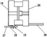
- Figure 20is a schematic structural view of the electric stapler in the embodiment of the present application after one side of the shell is removed;
- the proximal endis the direction close to the operator, and the distal end is the direction away from the operator.
- an electric stapleris provided.
- the stapler in this embodimentincludes a handle housing 10, an execution assembly 8, a driving motor 9, a connecting tube and a driving assembly.
- the handle housing 10is used to accommodate the drive motor 9 and a part of the drive assembly, and the drive assembly passes through the connecting pipe and is connected to the actuator assembly 8.
- the actuator assembly 8includes a clamping piece, a cutter and an actuator push rod 81.
- the rod 81is used to push the cutting knife to cut the tissue after the clamping member is closed. During this process, the staples are pushed out along with the advancement of the cutting knife, thereby realizing the stapling process.
- a built-in stapler power supplyis also provided in the handle housing 10, and the stapler power supply is used to supply power to the driving motor 9 to realize the electric driving process.
- the stapler power supplyis used to supply power to the driving motor 9 to realize the electric driving process.
- an electric stapler overload protection structureis designed, which is used to disconnect the power connection in time when the resistance is too large due to thicker tissue or other conditions during the tissue cutting process, so that the anastomosis The driving rack of the device no longer advances to prevent the stapler from being damaged or causing injury to the human body.
- an electric stapler overload protection structureis provided, which is suitable for electric staplers.
- the overload switching device in the staplerin the process of cutting tissue, when encountering thicker tissue or other conditions that cause excessive resistance, resulting in excessive thrust between the drive rack and the transition gear, it can pass through the deflection housing
- the coordinated design with the bias componentcan effectively separate the transition gear from the driving rack, realize the automatic disengagement of the electric stapler when the loading force is too large, avoid damage to the instrument and prevent accidental injury to the human body, and the structure is stable and reliable .
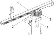
- a driving rack 1a driving gear 2 and an overload switching device.
- the distal end of the driving rack 1is used to push the executive assembly 8 of the electric stapler, specifically to push the actuator push rod 81 in the actuator assembly 8, so that the actuator assembly 8 performs the stapling action;
- the driving gear 2is used for transmission connection with the driving motor 9 of the electric stapler. Specifically, in this embodiment, the output shaft of the driving motor 9 is fixedly connected with the driving gear 2. The power is transmitted through the connection of the device.
- the overload switching deviceincludes a transition gear 3, a deflection housing 4, a deflection shaft 5 and a biasing assembly 6; through the above-mentioned structure of the overload switching device, when the thrust of the push rod 81 is too large, the transition The transmission connection relationship between the gear 3 and the drive rack 1 is disconnected, so as to realize the protection of the device.
- the transition gear 3meshes with the drive rack 1 and the drive gear 2 at the same time, and is used to transmit the driving force of the drive gear 2 to the drive rack 1; the transition gear 3 and the deflection housing 4 pass through the rotating shaft Rotationally connected, and the deflection housing 4 is rotationally connected to the deflection shaft 5, the biasing component 6 is used to provide a biasing force to the deflection housing 4, so that the deflection housing 4 provides the biasing force of the transition gear 3 towards the drive rack 1; therefore , when driving within a range less than the preset thrust, the transition gear 3 is always meshed with the driving rack 1 under the bias of the deflection housing 4 .
- the transition gear 3is set so that when the thrust between the driving rack 1 and the transition gear 3 is greater than a preset value, the transition gear 3 provides a disengagement thrust to the deflection housing 4 to overcome the bias force, so that the deflection housing 4 is relatively deflected. 5 rotates, and the transition gear 3 breaks away from the drive rack 1.
- the state of the biasing component 6is switched to restrict the deflection housing 4 from rotating relative to the deflection shaft 5 , that is, at this time, the biasing assembly 6 no longer provides a biasing force toward the drive rack 1 to the end of the deflection housing 4 provided with the transition gear 3 , but realizes the deflection through a latching structure or other locking structures
- the locking of the casing 4ensures that when the tissue is too thick to be fired, the stapler will not be automatically connected again after the transmission of the stapler is disengaged, thereby preventing false firing again.
- a reset button 7is also provided, which is used to detach the transition gear from the driving rack when the executive component fails and stops working during the anastomosis excitation process by pressing the reset button 7. Then manually retract the handle on the driving rack to open the jaws and separate from the tissue.
- a reset button 7is arranged outside one end of the deflection housing 4, and the reset button 7 is used to overcome the biasing force of the biasing component 6 to drive the transition gear 3 out of the driving rack 1.
- the biasing assembly 6specifically adopts the following specific structure to realize the above functions: the biasing assembly 6 includes a supporting boss 61, a supporting stop pin 62 and a biasing spring 63; One end of the accommodating chamber abuts against the inner wall of the accommodating chamber, the other end of the biasing spring 63 is sleeved on the support stop pin 62, and the end of the support stop pin 62 away from the bias spring 63 abuts against the support boss 61, and the support boss 61 is in contact with the bias The rotating shaft 5 is relatively fixed.
- the biasing spring 63is in a compressed state, so the two ends respectively provide pressure to the inner wall of the accommodation cavity and the support stop pin 62, and the support boss 61 provides a reactive support force to the support stop pin 62, so that the deflection housing 4 can continuously provide the The biasing force of the transition gear 3 towards the drive rack 1 .
- the specific direction of the forceis related to the direction of the force-bearing surface of the support boss 61 and the support pin 62, and can be adjusted according to actual needs.
- the support boss 61includes a limit plane and a transition slope
- one end of the support stop pin 62is provided with a stop pin slope 65 that matches the transition slope.
- the transition slope and the stop pin slope 65When the transition gear 3 is in the meshing position, the transition slope and the stop pin slope 65
- the deflection housing 4deflects from the transition gear 3 engagement position to the disengagement position by more than a preset angle, one end of the support pin 62 slides from the transition slope to the limit plane; as shown in Figure 8-9, in the initial state,
- the stop pin slope 65 of the support stop pin 62abuts against the transition slope of the support boss 61 and is decomposed into a horizontal force and a vertical force, wherein the vertical force is balanced with the axial force of the transition gear 3 .
- the deflection housing 4deflects from the transition gear 3 engagement position to the disengagement position by more than a preset angle, and the stop pin slope 65 supporting the stop pin 62 is separated from the transition slope of the support boss 61 , and then the plane of the support stop pin 62 is in contact with the limiting plane of the support boss 61, and the bias spring 63 continues to provide pressure to the support stop pin 62, so that the plane of the support stop pin 62 and the limit plane of the support boss 61 remain in contact. Then, through the switching of the contact surface, the direction of the force is changed, and the locking of the deflection housing 4 is realized.
- the accommodating chamber and the transition gear 3are located on both sides of the deflection shaft 5, the deflection housing 4 rotates around the deflection shaft 5, and the biasing assembly in the accommodating chamber maintains force balance with the transition gear 3 on both sides, so that The rotation control of the deflection housing 4 is realized, and finally the protective disengagement of the transition gear 3 is realized.
- a stop pin through holeis provided on the accommodation cavity, the outer diameter of the support stop pin 62 is less than or equal to the inner diameter of the stop pin through hole, and a limit boss 64 is provided on the support stop pin 62, and the limit protrusion
- the outer diameter of the platform 64is larger than the inner diameter of the through hole of the stopper pin, the limiting boss 64 is located in the receiving cavity, and one end of the supporting stopper pin 62 passes through the through hole of the stopper pin and abuts against the supporting boss 61 .
- the stopper pin through holeis set so that one end of the support stopper pin 62 connected to the bias spring 63 is limited in the accommodating cavity by the limiting boss 64, and the outer diameter of the limiting boss 64 is larger than the outer diameter of the biasing spring 63 .
- the outer diameter of the support stop pin 62is preferably equal to the inner diameter of the stop pin through hole, and the support stop pin 62 can apply a force perpendicular to the central axis of the support stop pin 62 to the stop pin through hole through the cylindrical side, thereby making the power transmission more stable reliable.
- the present inventionhas the following advantages compared with the prior art:
- the overload switching devicein the stapler, in the process of cutting tissue, when encountering thicker tissue or other conditions that cause excessive resistance, resulting in excessive thrust between the drive rack and the transition gear, it can pass through the deflection housing
- the coordinated design with the bias componentcan effectively separate the transition gear from the driving rack, realize the automatic disengagement of the electric stapler when the loading force is too large, avoid damage to the instrument and prevent accidental injury to the human body, and the structure is stable and reliable .
- the electric staplergenerally drives the rack through the motor to achieve two-stage drive.
- the first stageis the clamping stage.
- the opening of the execution end of the driven anastomosisis closed to clamp the tissue to be cut.
- the second stageis the cutting and anastomosis stage.
- the rackAdvance to realize the cutting and suturing of the end-to-tissue.
- the reverse rotation of the motorcan also realize the retraction of the cutter.
- the tissueAfter the first stage is completed, the tissue must be pressed for a certain period of time to prevent the tissue from rebounding, and it is necessary to confirm that the clamping position is accurate. It may cause the cutting knife to be driven forward without stable clamping, causing unnecessary injury. Therefore, it is necessary to provide an electric stapler stroke control mechanism capable of completing a safe stapling process to solve the above technical problems.
- the safety control componentcooperates with the first step surface and the second step surface of the driving rack, so that after the stapler completes the clamping action, it needs to perform the corresponding unlocking action when driving and cutting again, which ensures the safety of the entire use process.
- the mechanical mechanismis more stable and reliable than the circuit control.
- a stapler driving device with electric protection functionis provided, and the stapler driving device is specifically used in electric staplers.
- the start and stop of the driving componentis controlled by the switch control component, and the safety control component is used to prevent the switch control component from triggering by mistake in a specific stage.
- the stapler drive device in this embodimentincludes a drive assembly, a switch control assembly, and a safety control assembly, wherein the drive assembly is used to drive the execution assembly 8 of the stapler, and the drive assembly includes a drive rack 1 and a drive rack 1 for driving.
- the drive motor 9 of the rack 1as a preferred embodiment, in this embodiment, the drive motor 9 drives the drive rack 1 in a specific way that the drive assembly also includes a drive gear 2 and a transition gear 3, and the drive gear 2 and The output shaft of the drive motor 9 is driven and connected, and the transition gear 3 meshes with the drive gear 2 and the drive rack 1 at the same time.
- a switch control assemblyIn order to control the opening and closing of the driving motor 9, in the present embodiment, a switch control assembly is provided. Specifically, the switch control assembly includes a firing button 13 and a trigger switch 11. When the initial position is pressed to the firing position, the trigger switch 11 is triggered to turn on the drive motor 9 to drive the drive rack 1; in this embodiment, preferably, when pressed for the first time, the trigger switch 11 is triggered for the first time, and the drive motor 9 will drive the drive rack 1 to move the first preset stroke to the distal end, the first preset stroke corresponds to the stroke of the clamping tissue of the electric stapler, when the trigger switch 11 is pressed again, the drive motor 9 will drive the The rack 1 moves far to the second preset stroke, the second preset stroke is the cutting and stapling stroke of the electric stapler, this stroke can be the stroke that drives the driving rack 1 to the farthest end to complete the cutting and stapling, or It may be a stroke that drives the drive rack 1 to the farthest end and then returns
- the above processcan be realized by a stroke control unit.
- the stroke control unitcontrols the drive motor 9 to drive the drive rack 1 to advance to the first preset stroke and then stops. And when the trigger switch 11 is triggered again, continue to control the drive motor 9 to drive the drive rack 1 .
- the stroke control unitonly needs to use two preset strokes to control the step-by-step driving.
- the firing button 13is connected with a reset mechanism or element, such as a return spring, which can be released after the firing button 13 is pressed, and the firing button 13 returns to the original initial position, and the firing button 13 needs to be pressed again for the next stage of driving.
- the bottom of the driving rack 1is provided with a first stepped surface 311 and a second stepped surface 312 positioned at the proximal end of the first stepped surface 311;
- the safety control assemblyincludes a limiting block 21 and a biasing member 23, and the limiting block 21 is positioned on the driving tooth.
- the position of the limit block 21 of the safety control assemblycan also be changed in accordance with the contact mode between the first stepped surface 311 and the second stepped surface 312, so that Play and stop firing button 13 in time, to reach the purpose of safe locking.
- the first stepped surface 311 and the second stepped surface 312 of the driving rackare coordinated by the safety control component, so that after the stapler completes the clamping action, it needs to perform the corresponding unlocking action when it drives and cuts again.
- the safety of the whole use processis guaranteed.
- the second stepped surface 312is higher than the first stepped surface 311
- the limiting block 21is arranged below the driving rack 1
- the biasing member 23provides an upward biasing force to the limiting block 21, that is, in a
- the upper part of the limit block 21is abutted on the first stepped surface 311, and as the driving rack 1 moves forward to the position corresponding to the limit block 21 on the second stepped surface 312, the limit block 21 is biased.
- the firing button 13includes a relief groove 131 and a button protrusion 132
- the limit block 21is provided with a locking block 212.
- the locking block 212 and the relief groove 131The positions are corresponding, when the limiting block 21 is at the blocking position, the locking block 212 is corresponding to the position of the button protrusion 132 .
- the limit block 21is provided with a release drive part 211
- the release button 22is matched with the release drive part 211, so that when the limit block 21 is in the blocking position, the release button 22 is pressed to drive the release drive part 211, which can overcome the bias.
- the biasing force of the pressing member 23makes the limit block 21 in the unlocked position.
- the release drive part 211includes a drive ramp 213, and the release button 22 includes a drive ramp 221 that matches the drive ramp 213.
- the release button 22is horizontally positioned.
- the limit block 21When pressing, the limit block 21 is driven to move in the vertical direction, and when unlocking, only the release button 22 needs to be pressed in the horizontal direction to realize the unlocking of the internal mechanism. And when locking, there is an obvious feeling of being blocked, which is more intuitive than traditional circuit locking, so as to remind the operator of the current locking state.
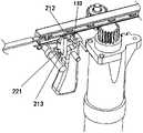
- the switch control assemblyalso includes a trigger connection Block 12, when the firing button 13 is pressed from the initial position to the firing position, the trigger connection block 12 is driven and contacts the trigger switch 11 to turn on the driving motor 9 to drive the driving rack 1, further preferably, the stapler driving device It also includes a transition connector 41, which is relatively fixedly connected to the shell of the stapler, and the firing button 13 and the trigger connection block 12 are both connected to the transition connection in rotation, and one end of the trigger connection block 12 is provided with a switch trigger part 121, and the other end A drive slot 122 is provided, and the firing button 13 is provided with a drive pin 14 matching the drive slot 122 .
- the firing button 13converts the action of pressing the handle into the action of pressing the trigger switch in another direction through the trigger connection block 12, the firing feel is more stable and comfortable, and the internal structure layout is also more compact and
- the power supply of the electric stapleris generally external and detachable. Every time the electric stapler needs to be used, the external battery pack can be plugged in and then used, and it can be discarded after unplugging, which ensures the one-time use of the battery pack.
- the built-in battery packis pre-installed in the inner cavity of the electric stapler, and the user cannot judge the use of the battery pack. Generally, after pressing the switch on the handle several times, it is impossible to judge whether the battery pack has been used in the next operation. . Therefore, it is necessary to provide a power control device for an electric stapler to improve the safety of the electric stapler and adapt to the structure of the built-in stapler to solve the above problems.
- an electric stapler power control deviceis provided.
- the power control device of the electric stapleris used to realize the on-off of the circuit.
- the power control deviceincludes a control switch assembly 30 and a power supply assembly and a circuit connection seat 26 located in the accommodating cavity of the handle housing 10, wherein, The power supply is placed in the handle housing 10 through the power supply installation structure, the power supply and the power supply installation structure together form a power supply assembly, the power supply assembly is electrically connected to the circuit connection seat 26, and the circuit connection seat 26 is provided with a driver for electrical connection with the stapler drive source.
- Press the elastic sheet 232, and the material of the pressed elastic sheet 232is preferably a copper sheet; the pressed elastic sheet 232 contacts the conductive block 231 after being pressed so that the two ends of the conductive block 231 are connected to each other, and the driving wire 28 is energized through the above-mentioned connected circuit, so as to transmit power To the driving motor of the electric stapler to realize the driving operation control.
- the so-called circuit connectionhere refers to the circuit connection between the power supply and the circuit connection seat, which is equivalent to the process of inserting the battery of the electric stapler with an external power supply. Further operations need to be controlled by the operation switch at the handle. .
- control switch assembly 30transmits the pressing action to the pressing elastic piece 232 by means of pressing, so that the pressing elastic piece 232 contacts the conductive block 231 after being pressed.
- the pressing control part 29is arranged on the proximal side of the first housing 19, so that the control switch assembly 30 is arranged on the proximal end of the handle housing 10 to correspond to it, which is more convenient for the operator to press; specifically, the control switch assembly 30 Including a pressing piece 31 and a triggering piece 32, the pressing piece 31 can be pressed from a first position to a second position, when the pressing piece 31 is in the first position, the triggering piece 32 is restricted from moving to the triggering position, and when the pressing piece 31 is in the second position , the trigger 32 can move from the initial position to the trigger position to drive the pressing control part 29 to the circuit-on position; when the trigger 32 is in the trigger position, the pressing member 31 is restricted from moving toward the first position.
- the control switch assembly 30Including a pressing piece 31 and a triggering piece 32, the pressing piece 31 can be pressed from a first position to a second position, when the pressing piece 31 is in the first position, the triggering piece 32 is restricted from moving to the triggering position,
- the first position and the second positionare only for the convenience of description, respectively corresponding to the initial position of the pressing member 31 before pressing, and the final position after pressing, the process from the first position to the second position, that is, the pressing member 31 31 relative to the process of sliding relative to the handle housing 10 .
- the control switch assemblycannot be retracted and reset, which prevents the risk caused by the power supply of the electric stapler being reused.
- the blocking fit of the pressing piece and the triggering piececan be realized through the projection fit, wherein, preferably, an elastic piece 33 is also used to further ensure that the pressing piece cannot be reset.
- the control switch assembly 30also includes providing the triggering piece 32 from the initial position
- the elastic member 33 of the bias force that moves to the trigger position, the elastic member 33is specifically a compression spring, is sleeved on the socket column that is arranged on the upper end of the trigger member 32 and cooperates with the spring, and continuously stops supplying to the trigger member 32 toward the pressing control part 29 the bias force.
- the pressing member 31When the pressing member 31 is in the first position, due to the existence of its protrusion, the downward movement of the trigger member 32 is blocked, and when the pressing member 31 is pressed to the second position, the raised part of the pressing member leaves the original blocking position. position, the trigger member 32 moves downward under the biasing force of the elastic member 33 , so as to realize the press trigger of the press control part 29 . And, after triggering, since the triggering member 32 moves downward to the triggering position, it limits the retraction direction of the projection of the original pressing key 31, thus preventing the reset and secondary use of the control switch assembly 30.
- the side of the pressing member 31is provided with a first raised portion 34
- the side of the trigger member 32is provided with a second raised portion 321.
- the top of the first raised portion 34The surface is in contact with the lower surface of the second raised portion 321 to limit the movement of the trigger member 32 to the trigger position; contact to limit the movement of the pressing member 31 to the first position.
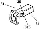
- the first protrusion 34includes a V-shaped groove 35
- the V-shaped groove 35includes a first slope 313 facing the second position
- the second protrusion 321is provided with a second slope matching the first slope 313 322
- the first inclined surface 313is in contact with the second inclined surface 322
- the second inclined surface 322applies a biasing force toward the first position to the first inclined surface 313 under the action of the elastic member 33, thus effectively preventing false triggering of the pressing member 31, as long as the first inclined surface 313 does not push through the second inclined surface 322, Then the pressing member 31 can always be reset to the first position.
- the first inclined surface 313squeezes through the second inclined surface 322 and breaks away from it.
- the trigger member 32which is not constrained by the pressing member 31, moves downward through the action of the elastic member 33, triggering Press the control part to realize the power on.
- the design of the V-shaped groovecan prevent the misoperation of the control switch assembly.
- the pressing partWhen the pressing does not exceed the preset distance, the pressing part will automatically reset to the original first position, ensuring the safety of the electric stapler.
- the pressing member 31when the pressing member 31 is at the first position, the pressing member 31 is at least partially located outside the housing cavity of the handle housing 10, and the pressing member 31 passes through the handle housing 10 to contact the trigger member 32, and when the pressing member 31 is at the second position , the pressing parts 31 are all located in the handle housing 10, so as to be convenient for the operator to press.
- the circuit connection seat 26is arranged under the power supply installation housing 18, and the circuit connection seat 26 is provided with a driving wire 28 for electrically connecting with the driving source of the stapler and a pressing control part 29 for controlling the on-off of the circuit;
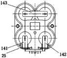
- the conductive sheet The assembly 25includes a positive electrode conductive sheet 141 and a negative electrode conductive sheet 142.
- the positive electrode conductive sheet 141 and the negative electrode conductive sheet 142are electrically connected to the two ends of the conductive block 231 respectively, and are specifically plugged into the slot of the connection base 27, and the connection base and the conductive block 231 Both ends are also designed for circuit conduction;
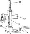
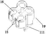
- the built-in stapler power supply installation structureincludes a power supply installation housing 18 and a circuit connection seat 26, wherein the power supply installation housing 18 is provided with a plurality of battery installation cavities 16, and the plurality of battery installation cavities 16 are symmetrically arranged;
- the installation housing 18includes a first housing 19 and a second housing 20 that are detachably connected; the second housing 20 is located on the far side of the first housing 19;
- the first housing 19is provided with a conductive sheet assembly 25 electrically connected to the circuit connection seat 26; the power supply installation housing 18 is provided with a wire clearance slot 24 for driving wires 28 to pass through, and the driving wires can be installed in the power supply housing.
- the wire relief slot 24is disposed under the second housing 20 .
- the position of the pressing control part that controls the on-off of the circuitis more suitable for additionally setting the corresponding push switch for pressing operation, and the driving wire can give way to the wire of the power supply installation shell Under the protection of the groove, it does not take up extra space and plays a role of limit protection.
- the bottom of the power supply installation housing 18is provided with a positioning pin
- the circuit connection seat 26is provided with a positioning pin that is plugged and matched with the positioning pin 15.
- Hole 271after the two are mated and inserted, positioning connection can be realized, and at this time, the conductive sheet assembly 25 can also correspond to the slot of the connection base 27 .
- the conductive sheet assembly 25also includes battery connection guides 143 for electrically connecting batteries in different battery installation chambers 16, which are respectively provided on one side of the first housing 19 with horizontal guides for connecting the upper two batteries.
- the battery connection guide piece 143 and the two connection guide pieces 143 on the other side of the second housingrespectively connect the upper and lower batteries, so that the four batteries can form a series circuit after being placed in the battery installation cavity 16 .
- the number of battery installation cavities 16is four, and four battery installation cavities 16 are provided with two above and below, and the lower part of the first housing 19 corresponds to the openings of the two battery installation cavities 16.
- the negative electrode conductive sheet 142 and the upper part of the first casing 19are provided with a battery connection guide sheet 143 transversely corresponding to the opening of the battery installation chamber 16 .
- the first housing 19 and the second housing 20are detachably connected, and the specific implementation method is that the first housing 19 is provided with a first connecting portion 111, and the second housing 19 20 is provided with a second connecting portion 201, and the first connecting portion 111 and the second connecting portion 201 are detachably connected by bolts.
- the middle part of the power supply installation housing 18is provided with a pressing relief groove 17, and when the pressing member 31 is in the second position, it is at least partially located in the pressing relief groove 17.
- the power supply installation housing 18is provided with a A plurality of battery installation cavities 16, specifically preferably four, a plurality of battery installation cavities 16 are symmetrically arranged; the pressing relief groove 17 is located at the symmetrical center of the plurality of battery installation cavities 16, through the above-mentioned symmetrical arrangement and pressing the relief groove, reasonable saving
- the space of the overall structuremakes the distance of the pressing process more in line with the operator's feel.
- references herein to "one embodiment” or “an embodiment”refers to a specific feature, structure or characteristic that may be included in at least one implementation of the present application.
- the orientation or positional relationship indicated by the terms “upper”, “lower”, “top”, “bottom” etc.is based on the orientation or positional relationship shown in the drawings, and is only for It is convenient to describe the application and simplify the description, but not to indicate or imply that the device or element referred to must have a specific orientation, be constructed and operate in a specific orientation, and thus should not be construed as limiting the application.
Landscapes
- Health & Medical Sciences (AREA)
- Life Sciences & Earth Sciences (AREA)
- Surgery (AREA)
- Heart & Thoracic Surgery (AREA)
- Engineering & Computer Science (AREA)
- Biomedical Technology (AREA)
- Nuclear Medicine, Radiotherapy & Molecular Imaging (AREA)
- Medical Informatics (AREA)
- Molecular Biology (AREA)
- Animal Behavior & Ethology (AREA)
- General Health & Medical Sciences (AREA)
- Public Health (AREA)
- Veterinary Medicine (AREA)
- Portable Nailing Machines And Staplers (AREA)
Abstract
Description
Translated fromChinese本发明涉及一种医疗器械,尤其涉及一种电动吻合器、吻合器驱动装置及吻合器电源控制装置。The invention relates to a medical device, in particular to an electric stapler, a stapler driving device and a stapler power control device.
吻合器自诞生以来经历了多次设计改进,从原始的医用“订书机”成为吻合器,并在经历了第一代开放式吻合器、第二代腔镜吻合器的两个技术阶段后开始步入第三代电动腔镜吻合时代。相较于手动吻合器,电动腔镜吻合器具有更好的止血效果,因此在临床价值和经济价值上都有了提升。The stapler has undergone many design improvements since its birth, from the original medical "stapler" to a stapler, and after going through the two technical stages of the first generation of open stapler and the second generation of laparoscopic stapler Beginning to enter the era of the third generation electric endoscopic anastomosis. Compared with manual staplers, electric endoscopic staplers have a better hemostatic effect, so their clinical value and economic value have been improved.
腔内吻合器通常可包括两个细长的钳口构件,这两个钳口构件分别用于抓取或夹紧组织。在某些手术用吻合器中,其中一个钳口构件具有装载了多个布置成至少两横排的吻合钉的吻合钉钉仓,而另一钳口构件具有砧座,在吻合钉从吻合钉钉仓被推出时,该砧座限定了用于形成吻合钉腿的表面。吻合操作中,通过推动刀片,从而顺序将吻合钉从吻合钉钉仓中射出,刀片可在吻合钉排之间行进,用来纵向切割吻合钉排间被吻合起来的组织。Endoluminal staplers may generally include two elongated jaw members for grasping or clamping tissue, respectively. In some surgical staplers, one of the jaw members has a staple magazine loaded with a plurality of staples arranged in at least two horizontal rows, and the other jaw member has an anvil, which When the staple cartridge is pushed out, the anvil defines a surface for forming the staple legs. During the stapling operation, the staples are sequentially ejected from the staple cartridge by pushing the blade, and the blade can travel between rows of staples to longitudinally cut the stapled tissues between the rows of staples.
在手动吻合器中,切割时的推力可以通过操作者的手进行感受,从而在推力过大时及时停止操作,而在电动吻合器中,对于切割到较厚组织或者其他突发推力增大的情况时,电机无法及时停止操作,设置传感器和控制器等电子元件的成本较高,且控制程序出现故障时,也无法实现停机控制,容易造成危险。因此需要提供一种具有稳定可靠功能的电动吻合器过载保护结构来解决上述技术问题。In the manual stapler, the thrust during cutting can be felt by the operator’s hand, so that the operation can be stopped in time when the thrust is too large, while in the electric stapler, for cutting thicker tissues or other sudden increase in thrust In case of emergency, the motor cannot be stopped in time, and the cost of installing electronic components such as sensors and controllers is high, and when the control program fails, the shutdown control cannot be realized, which is likely to cause danger. Therefore, it is necessary to provide an electric stapler overload protection structure with stable and reliable functions to solve the above technical problems.
发明内容Contents of the invention
为了解决上述技术问题,本发明通过对结构进行改进,可以使得电动吻合器在遇到加载力过大时自动脱开,避免对器械破坏以及防止对人体造成意外伤害,且结构稳定可靠。本发明的技术方案是这样实现的:In order to solve the above technical problems, the present invention improves the structure so that the electric stapler can be disengaged automatically when the loading force is too large, avoiding damage to the instrument and preventing accidental injury to the human body, and the structure is stable and reliable. Technical scheme of the present invention is realized like this:
本申请技术方案为提供一种电动吻合器过载保护结构,进一步优选地,包括:The technical solution of the present application is to provide an electric stapler overload protection structure, which further preferably includes:
驱动齿条,所述驱动齿条远端用于推动电动吻合器的执行组件;A driving rack, the distal end of which is used to push the executive assembly of the electric stapler;
驱动齿轮,所述驱动齿轮用于与电动吻合器的驱动电机传动连接;A driving gear, the driving gear is used for transmission connection with the driving motor of the electric stapler;
过载切换装置,所述过载切换装置包括过渡齿轮、偏转壳体、偏转轴和偏压组件;an overload switching device, the overload switching device includes a transition gear, a deflection housing, a deflection shaft and a biasing assembly;
所述过渡齿轮同时与所述驱动齿条和驱动齿轮啮合,用于将驱动齿轮的驱动力传递至所述驱动齿条;The transition gear meshes with the driving rack and the driving gear at the same time, and is used to transmit the driving force of the driving gear to the driving rack;
所述过渡齿轮与所述偏转壳体转动连接,且所述偏转壳体转动连接于所述偏转轴,所述偏压组件用于向所述偏转壳体提供偏压力,以使得所述偏转壳体提供所述过渡齿轮朝向所述驱动齿条的偏压力;The transition gear is rotatably connected to the deflection housing, and the deflection housing is rotatably connected to the deflection shaft, and the biasing component is used to provide a bias force to the deflection housing, so that the deflection housing body provides a biasing force of the transition gear towards the drive rack;
所述过渡齿轮被设置为,当所述驱动齿条与所述过渡齿轮之间推力大于预设值时,所述过渡齿轮向所述偏转壳体提供克服所述偏压力的脱离推力,以使得所述偏转壳体相对所述偏转轴转动,所述过渡齿轮脱离所述驱动齿条。The transition gear is configured such that when the thrust between the drive rack and the transition gear is greater than a preset value, the transition gear provides a disengagement thrust to the deflection housing to overcome the biasing force, so that The deflection housing rotates relative to the deflection shaft, and the transition gear is disengaged from the drive rack.
进一步优选地,所述偏转壳体从所述过渡齿轮啮合位置向脱离位置偏转超过预设角度时,所述偏压组 件的状态切换为限制所述偏转壳体相对所述偏转轴转动。Further preferably, when the deflection housing is deflected from the transition gear engagement position to the disengagement position by more than a preset angle, the state of the biasing component is switched to restrict the rotation of the deflection housing relative to the deflection shaft.
进一步优选地,所述偏压组件包括支撑凸台、支撑挡销和偏压弹簧;所述偏转壳体设有容纳腔,所述偏压弹簧位于所述容纳腔且一端与所述容纳腔内壁抵接,所述偏压弹簧另一端套设于所述支撑挡销,所述支撑挡销远离所述偏压弹簧的一端与所述支撑凸台抵接,所述支撑凸台与所述偏转轴相对固定。Further preferably, the biasing assembly includes a supporting boss, a supporting pin and a biasing spring; the deflecting housing is provided with a housing chamber, the biasing spring is located in the housing chamber and one end is connected to the inner wall of the housing chamber The other end of the bias spring is sheathed on the support stop pin, and the end of the support stop pin away from the bias spring is in contact with the support boss, and the support boss is in contact with the bias spring. The rotating shaft is relatively fixed.
进一步优选地,所述容纳腔与所述过渡齿轮位于所述偏转轴的两侧。Further preferably, the accommodating chamber and the transition gear are located on both sides of the deflection shaft.
进一步优选地,所述容纳腔上设有挡销通孔,所述支撑挡销的外径小于等于所述挡销通孔的内径,所述支撑挡销上设有限位凸台,所述限位凸台的外径大于所述挡销通孔的内径,所述限位凸台位于所述容纳腔内,且所述支撑挡销的一端穿过所述挡销通孔后抵接于所述支撑凸台。Further preferably, the accommodating cavity is provided with a stop pin through hole, the outer diameter of the support stop pin is less than or equal to the inner diameter of the stop pin through hole, the support stop pin is provided with a limiting boss, the limit The outer diameter of the position boss is larger than the inner diameter of the through hole of the stop pin, the stop boss is located in the accommodating cavity, and one end of the support stop pin passes through the through hole of the stop pin and abuts against the stop pin through hole. The above-mentioned support boss.
进一步优选地,支撑凸台包括限位平面与过渡斜面,所述支撑挡销一端设有与所述过渡斜面相匹配的挡销斜面,当所述过渡齿轮处于啮合位置时,所述过渡斜面与挡销斜面贴合,且所述偏转壳体从所述过渡齿轮啮合位置向脱离位置偏转超过预设角度时,所述支撑挡销一端从所述过渡斜面滑动至所述限位平面。Further preferably, the supporting boss includes a limiting plane and a transition slope, and one end of the support stop pin is provided with a stop pin slope matching the transition slope, and when the transition gear is in the meshing position, the transition slope and the transition slope When the slope of the stopper pin fits, and the deflection housing deflects from the engagement position of the transition gear to the disengagement position by more than a preset angle, one end of the support stopper slides from the slope of the transition to the limit plane.
进一步优选地,所述偏转壳体设有复位按钮,所述复位按钮用于克服所述偏压组件的偏压力,以驱动所述过渡齿轮脱离所述驱动齿条。Further preferably, the deflection housing is provided with a reset button for overcoming the biasing force of the biasing assembly to drive the transition gear away from the drive rack.
另一方面,提供一种电动吻合器,包括执行组件、驱动电机以及如上所述的电动吻合器过载保护结构。In another aspect, an electric stapler is provided, including an executive component, a driving motor, and the above-mentioned overload protection structure of the electric stapler.
进一步地,通过安全控制组件配合驱动齿条的第一台阶面和第二台阶面,使得吻合器在完成夹持动作后,再次驱动切割需要进行相应的解锁动作,保证了整个使用过程的安全性,机械机构相比于电路控制更加稳定可靠。Further, through the safety control component cooperating with the first step surface and the second step surface of the driving rack, after the stapler completes the clamping action, it needs to perform the corresponding unlocking action when it is driven to cut again, which ensures the safety of the whole use process , the mechanical mechanism is more stable and reliable than the circuit control.
本申请提供一种具有保护功能的吻合器驱动装置,包括:The application provides a stapler driving device with protection function, including:
驱动组件,所述驱动组件用于驱动吻合器的执行组件,所述驱动组件包括驱动齿条和用于驱动所述驱动齿条的驱动电机,所述驱动齿条的下部设有第一台阶面以及位于第一台阶面近端的第二台阶面;A drive assembly, the drive assembly is used to drive the execution assembly of the stapler, the drive assembly includes a drive rack and a drive motor for driving the drive rack, the lower part of the drive rack is provided with a first stepped surface and a second stepped surface located at the proximal end of the first stepped surface;
开关控制组件,所述开关控制组件包括击发按钮和触发开关,所述击发按钮从初始位置被按压至击发位置时,触发开关被触发,以打开驱动电机对驱动齿条进行驱动;A switch control assembly, the switch control assembly includes a firing button and a trigger switch, when the firing button is pressed from the initial position to the firing position, the trigger switch is triggered to turn on the drive motor to drive the drive rack;
安全控制组件,所述安全控制组件包括限位块和偏压件,所述限位块在所述驱动齿条往远端运动第一预设行程后,在所述偏压件作用下从与所述第一台阶面接触的解锁位置变换为与所述第二台阶面接触的阻挡位置,所述限位块位于阻挡位置时限定所述击发按钮从初始位置被按压至击发位置。A safety control assembly, the safety control assembly includes a limit block and a biasing member, and after the driving rack moves to the first preset stroke far, the limit block moves from and to the biasing member under the action of the biasing member. The unlocking position in contact with the first stepped surface is transformed into a blocking position in contact with the second stepped surface, and when the limiting block is in the blocking position, the firing button is restricted from being pressed from an initial position to a firing position.
进一步优选地,所述开关控制组件还包括触发连接块,所述击发按钮从初始位置被按压至击发位置时,触发连接块被驱动并接触触发开关,以打开驱动电机来对驱动齿条进行驱动。Further preferably, the switch control assembly further includes a trigger connection block, when the firing button is pressed from the initial position to the firing position, the trigger connection block is driven and contacts the trigger switch to turn on the drive motor to drive the drive rack .
进一步优选地,所述吻合器驱动装置还包括过渡连接件,所述过渡连接件与吻合器的壳体相对固定连接,所述击发按钮与所述触发连接块均与所述过渡连接转动连接,所述触发连接块一端设有开关触发部,另一端设有驱动槽,所述击发按钮设有与所述驱动槽相匹配的驱动销。Further preferably, the stapler driving device further includes a transitional connection piece, the transitional connection piece is relatively fixedly connected to the shell of the stapler, the firing button and the trigger connection block are both rotatably connected to the transitional connection, One end of the trigger connection block is provided with a switch trigger part, and the other end is provided with a drive slot, and the firing button is provided with a drive pin matching the drive slot.
进一步优选地,驱动组件还包括驱动齿轮和过渡齿轮,所述驱动齿轮与所述驱动电机输出轴驱动连接,所述过渡齿轮同时与所述驱动齿轮以及所述驱动齿条啮合。Further preferably, the driving assembly further includes a driving gear and a transition gear, the driving gear is drivingly connected to the output shaft of the driving motor, and the transition gear meshes with the driving gear and the driving rack at the same time.
进一步优选地,还包括行程控制单元,所述行程控制单元在所述触发开关被第一次触发时,控制所述驱动电机驱动所述驱动齿条前进第一预设行程后停止,并且在所述触发开关被再次触发时继续控制所述驱 动电机驱动所述驱动齿条。Further preferably, a stroke control unit is further included, and when the trigger switch is triggered for the first time, the stroke control unit controls the drive motor to drive the drive rack to stop after a first preset stroke, and stops when the trigger switch is triggered for the first time. When the trigger switch is triggered again, the drive motor is continuously controlled to drive the drive rack.
进一步优选地,所述第二台阶面高于所述第一台阶面,所述限位块设于所述驱动齿条下方,所述偏压件向所述限位块提供向上的偏压力。Further preferably, the second stepped surface is higher than the first stepped surface, the limiting block is disposed below the driving rack, and the biasing member provides an upward biasing force to the limiting block.
进一步优选地,所述击发按钮包括让位槽和按钮凸起部,所述限位块设有锁定挡块,所述限位块位于解锁位置时,所述锁定挡块与所述让位槽位置相对应,所述限位块位于阻挡位置时,所述锁定挡块与所述按钮凸起部位置相对应。Further preferably, the firing button includes a relief groove and a button protrusion, and the limiting block is provided with a locking block, and when the limiting block is in the unlocked position, the locking block and the relief groove The positions are corresponding, and when the limiting block is at the blocking position, the locking block is corresponding to the position of the protrusion of the button.
进一步优选地,还包括释放钮,所述限位块设有释放驱动部,所述释放钮与所述释放驱动部相匹配,以使得当所述限位块位于阻挡位置,按压释放钮驱动所述释放驱动部,能够克服所述偏压件的偏压力使得所述限位块位于解锁位置。Further preferably, it also includes a release button, the limit block is provided with a release driving part, and the release button is matched with the release drive part, so that when the limit block is at the blocking position, pressing the release button drives the The release driving part can overcome the biasing force of the biasing member so that the limiting block is located at the unlocking position.
进一步优选地,所述释放驱动部包括驱动斜块,所述释放钮包括与所述驱动斜块相匹配的驱动斜面,所述释放钮在水平方向按压时驱动所述限位块在垂直方向移动。Further preferably, the release driving part includes a driving ramp, the release button includes a driving ramp matching the driving ramp, and when the release button is pressed in the horizontal direction, it drives the limit block to move in the vertical direction .
另外,本申请还提供一种电动吻合器,包括如上所述的吻合器驱动装置。In addition, the present application also provides an electric stapler, including the above-mentioned stapler driving device.
通过具有保护功能的吻合器驱动装置的设置,本申请具有如下优点:Through the setting of the stapler driving device with protection function, the present application has the following advantages:
(1)通过安全控制组件配合驱动齿条的第一台阶面和第二台阶面,使得吻合器在完成夹持动作后,再次驱动切割需要进行相应的解锁动作,保证了整个使用过程的安全性,机械机构相比于电路控制更加稳定可靠。(1) Cooperate with the first step surface and the second step surface of the driving rack through the safety control component, so that after the stapler completes the clamping action, it needs to perform the corresponding unlocking action when driving and cutting again, ensuring the safety of the entire use process , the mechanical mechanism is more stable and reliable than the circuit control.
(2)进行解锁时,仅需在水平方向按压释放钮,即可实现内部的机构解锁。且在锁定时,有明显的被阻挡的手感,相比于传统的电路锁定更加能够直观的感受,以提醒操作者当前的锁定状态。(2) When unlocking, you only need to press the release button in the horizontal direction to realize the unlocking of the internal mechanism. And when locking, there is an obvious feeling of being blocked, which is more intuitive than traditional circuit locking, so as to remind the operator of the current locking state.
(3)击发按钮通过触发连接块将按压手柄的动作转换为了另一个方向按压触发开关的动作,击发手感更加稳定舒适,内部结构布置也更加紧凑合理。(3) The firing button converts the action of pressing the handle into the action of pressing the trigger switch in another direction through the trigger connection block. The firing feel is more stable and comfortable, and the internal structure layout is more compact and reasonable.
进一步地,通过按压件和触发件的阻挡配合,使得电源在使用过一次后,控制开关组件即无法回退复位,防止了电动吻合器的电源被二次利用导致的风险。Furthermore, through the blocking cooperation between the pressing member and the triggering member, the control switch assembly cannot be retracted and reset after the power supply is used once, which prevents the risk of the power supply of the electric stapler being used again.
本申请提供一种电动吻合器电源控制装置,包括:控制开关组件以及位于手柄壳体容纳腔内的电源组件和电路连接座;The present application provides a power control device for an electric stapler, including: a control switch assembly, a power supply assembly and a circuit connection seat located in the housing chamber of the handle;
所述电源组件和电路连接座电连接,所述电路连接座上设有用于与吻合器驱动源电连接的驱动导线以及用于控制电路接通和断开的按压控制部;The power supply assembly is electrically connected to the circuit connection seat, and the circuit connection seat is provided with a driving wire for electrically connecting with the stapler driving source and a pressing control part for controlling the connection and disconnection of the circuit;
所述控制开关组件包括按压件和触发件,所述按压件能够从第一位置被按压至第二位置,所述按压件位于第一位置时限制所述触发件向触发位置移动,且所述按压件位于第二位置时,所述触发件能够从初始位置向触发位置移动,以驱动所述按压控制部至电路接通位置;The control switch assembly includes a pressing piece and a triggering piece, the pressing piece can be pressed from a first position to a second position, when the pressing piece is in the first position, the triggering piece is restricted from moving to the triggering position, and the When the pressing part is in the second position, the triggering part can move from the initial position to the triggering position, so as to drive the pressing control part to the circuit-on position;
所述触发件位于触发位置时限制所述按压件向第一位置的方向移动。When the triggering part is in the triggering position, the pressing part is restricted from moving toward the first position.
进一步地,所述控制开关组件还包括提供所述触发件从初始位置向触发位置移动的偏压力的弹性件。Further, the control switch assembly further includes an elastic member providing a biasing force for the trigger member to move from an initial position to a trigger position.
进一步地,所述按压件侧面设有第一凸起部,所述触发件侧面设有第二凸起部,所述按压件位于第一位置时,所述第一凸起部的上表面与第二凸起部的下表面接触,以限制所述触发件向触发位置移动;所述按压件位于第二位置时,所述第二凸起部的侧壁与所述第一凸起部的侧面相接触,以限制所述按压件向第一位置移动。Further, a first protrusion is provided on the side of the pressing member, and a second protrusion is provided on the side of the triggering member. When the pressing member is in the first position, the upper surface of the first protrusion is in contact with the The lower surface of the second protrusion is in contact with each other to limit the movement of the trigger member to the trigger position; when the pressing member is at the second position, the side wall of the second protrusion is in contact with the side wall of the first protrusion The side faces are in contact with each other so as to limit the pressing part from moving to the first position.
进一步地,所述第一凸起部包括V型槽,所述V型槽包括朝向第二位置的第一斜面,所述第二凸起部设有与所述第一斜面相匹配的第二斜面,所述按压件位于第一位置时,所述第一斜面与所述第二斜面相接触。Further, the first protrusion includes a V-shaped groove, the V-shaped groove includes a first slope facing the second position, and the second protrusion is provided with a second slope that matches the first slope. An inclined surface, when the pressing member is at the first position, the first inclined surface is in contact with the second inclined surface.
进一步地,所述按压件位于第一位置时,所述按压件至少部分位于所述手柄壳体容纳腔外,且所述按压件穿过所述手柄壳体与所述触发件接触,所述按压件位于第二位置时,所述按压件全部位于所述手柄壳体内。Further, when the pressing member is in the first position, the pressing member is at least partly located outside the accommodating cavity of the handle housing, and the pressing member passes through the handle housing and contacts the trigger member, the When the pressing member is in the second position, the pressing member is entirely located in the handle housing.
进一步地,所述电源组件包括电源安装壳体,所述电路连接座设于所述电源安装壳体下方,所述按压控制部设于电源安装壳体的近端一侧,所述电源安装壳体下方设有供驱动导线穿过的导线让位槽。Further, the power supply assembly includes a power supply installation case, the circuit connection seat is arranged under the power supply installation case, the pressing control part is arranged on the proximal side of the power supply installation case, and the power supply installation case Under the body, there is a wire give way slot for the driving wire to pass through.
进一步地,所述电源安装壳体设有与所述电路连接座电连接的导电片组件;所述按压控制部包括导电块和设于导电块上的按压弹性片,所述导电片组件包括正极导电片和负极导电片,所述正极导电片和所述负极导电片分别与所述导电块两端电连接。Further, the power supply installation housing is provided with a conductive sheet assembly electrically connected to the circuit connection seat; the pressing control part includes a conductive block and a pressing elastic sheet arranged on the conductive block, and the conductive sheet assembly includes a positive pole A conductive sheet and a negative conductive sheet, the positive conductive sheet and the negative conductive sheet are respectively electrically connected to two ends of the conductive block.
进一步地,所述电源安装壳体中部设有按压让位槽,所述按压件位于第二位置时至少部分位于所述按压让位槽内。Further, a pressing relief groove is provided in the middle of the power supply installation housing, and when the pressing member is in the second position, it is at least partially located in the pressing relief groove.
进一步地,所述电源安装壳体内设有多个电池安装腔,多个所述电池安装腔对称设置;所述按压让位槽位于多个所述电池安装腔对称中心。Further, a plurality of battery installation cavities are arranged inside the power supply installation housing, and the plurality of battery installation cavities are arranged symmetrically; the pressing relief groove is located at the symmetrical centers of the plurality of battery installation cavities.
另一方面,本申请提供一种电动吻合器,包括如上所述的一种电动吻合器电源控制装置。In another aspect, the present application provides an electric stapler, including the power control device for the electric stapler as described above.
通过电源控制装置的设置,本申请具有下列优点:Through the setting of the power control device, the application has the following advantages:
(1)通过按压件和触发件的阻挡配合,使得电源在使用过一次后,控制开关组件即无法回退复位,防止了电动吻合器的电源被二次利用导致的风险;(1) Through the blocking cooperation between the pressing part and the triggering part, after the power supply is used once, the control switch assembly cannot be retracted and reset, which prevents the risk caused by the power supply of the electric stapler being reused;
(2)通过V型槽的设计可以防止控制开关组件的误操作,在按压不超过预设的距离的情况下,按压件会自动复位到原始的第一位置,保证了电动吻合器的安全性;(2) The design of the V-shaped groove can prevent the misoperation of the control switch assembly. When the pressing does not exceed the preset distance, the pressing part will automatically reset to the original first position, ensuring the safety of the electric stapler ;
(3)通过电源安装壳体与电路连接座的紧密配合,使得控制电路通断的按压控制部的位置更适应于额外设置对应的按压开关进行按压操作,且驱动导线能够在电源安装壳体的导线让位槽的保护下,不占用额外的空间且起到了限位保护作用。(3) Through the close fit between the power supply installation shell and the circuit connection seat, the position of the pressing control part that controls the on-off of the circuit is more suitable for additionally setting the corresponding push switch for pressing operation, and the driving wire can be in the power supply installation shell. Under the protection of the wire give way groove, it does not take up extra space and plays the role of limit protection.
由于上述技术方案运用,本发明与现有技术相比具有下列优点:Due to the use of the above-mentioned technical solutions, the present invention has the following advantages compared with the prior art:
通过在吻合器中设置过载切换装置,使得在切割组织过程中,遇到较厚的组织或其它情况造成阻力过大,造成驱动齿条与过渡齿轮之间推力过大时,可以通过偏转壳体和偏压组件的配合设计,有效将过渡齿 轮与驱动齿条脱离,实现电动吻合器在遇到加载力过大时自动脱开,避免对器械破坏以及防止对人体造成意外伤害,且结构稳定可靠。By setting the overload switching device in the stapler, in the process of cutting tissue, when encountering thicker tissue or other conditions that cause excessive resistance, resulting in excessive thrust between the drive rack and the transition gear, it can pass through the deflection housing The coordinated design with the bias component can effectively separate the transition gear from the driving rack, realize the automatic disengagement of the electric stapler when the loading force is too large, avoid damage to the instrument and prevent accidental injury to the human body, and the structure is stable and reliable .
附图1为本申请实施例整体外部结构示意图;Accompanying drawing 1 is a schematic diagram of the overall external structure of the embodiment of the present application;
附图2为图1去除部分壳体后的过载保护结构的结构示意图;Accompanying drawing 2 is the schematic diagram of the structure of the overload protection structure after part of the shell is removed in Fig. 1;
附图3为图2的结构爆炸图;Accompanying drawing 3 is the structural explosion diagram of Fig. 2;
附图4为本申请实施例过载保护结构的局部放大图;Accompanying drawing 4 is the partially enlarged view of the overload protection structure of the embodiment of the present application;
附图5为附图4去除偏转壳体后的结构示意图;Accompanying drawing 5 is the schematic structural diagram of drawing 4 after removing the deflection housing;
附图6为本申请实施例的驱动齿条、驱动齿轮以及过渡齿轮之间的传动原理图;Accompanying drawing 6 is the schematic diagram of the transmission between the driving rack, the driving gear and the transition gear according to the embodiment of the present application;
附图7(a)、(b)、(c)为本申请实施例过渡齿轮和驱动齿条的受力分析图;Accompanying drawing 7 (a), (b), (c) are the stress analysis diagrams of the transition gear and the driving rack of the embodiment of the present application;
附图8为过渡齿轮和驱动齿条啮合时的支撑挡销的受力分析图;Accompanying drawing 8 is the force analysis diagram of the support stop pin when the transition gear and the driving rack mesh;
附图9为过渡齿轮和驱动齿条脱离时的结构示意图;Accompanying drawing 9 is the structural representation when the transition gear and the drive rack are disengaged;
附图10为本申请实施例吻合器驱动装置的爆炸结构示意图;Accompanying drawing 10 is the schematic diagram of the explosion structure of the stapler driving device of the embodiment of the present application;
附图11为击发按钮按压前的局部正视图;Accompanying drawing 11 is a partial front view before the firing button is pressed;
附图12为击发按钮按压后的局部正视图;Accompanying drawing 12 is the partial front view after firing button is pressed;
附图13为限位块在解锁位置时吻合器驱动装置的立体结构示意图;Accompanying drawing 13 is the three-dimensional structure diagram of the stapler driving device when the limit block is in the unlocked position;
附图14为限位块在解锁位置且击发按钮按压后吻合器驱动装置的正视图;Accompanying drawing 14 is the front view of the stapler driving device after the limit block is in the unlocked position and the firing button is pressed;
附图15为限位块在锁定位置时吻合器驱动装置的立体结构示意图;Accompanying drawing 15 is the three-dimensional structure diagram of the stapler driving device when the limit block is in the locked position;
附图16为限位块在解锁位置时吻合器驱动装置的正视图;Accompanying drawing 16 is the front view of the stapler driving device when the limit block is in the unlocked position;
附图17为释放钮将限位块从锁定位置驱动至解锁位置时吻合器驱动装置的立体结构示意图;Accompanying drawing 17 is the three-dimensional structural diagram of the stapler driving device when the release button drives the limit block from the locked position to the unlocked position;
附图18为图17的正视图;Accompanying drawing 18 is the front view of Fig. 17;
附图19为触发连接块两个不同视角的零件结构示意图;Accompanying drawing 19 is the part structure diagram of two different viewing angles of the trigger connection block;
附图20为本申请实施例中电动吻合器去除一侧壳体后的结构示意图;Figure 20 is a schematic structural view of the electric stapler in the embodiment of the present application after one side of the shell is removed;
附图21为附图20的局部立体结构示意图;Accompanying drawing 21 is the partial three-dimensional structure schematic diagram of accompanying drawing 20;
附图22为附图20的局部放大正视图;Accompanying drawing 22 is the partially enlarged front view of accompanying drawing 20;
附图23为附图22去除按压件后的正视图;Accompanying drawing 23 is the front view of accompanying drawing 22 after removing the pressing piece;
附图24为本申请控制开关组件的立体结构示意图;Accompanying drawing 24 is the three-dimensional structure diagram of the control switch assembly of the present application;
附图25为本申请按压件的结构示意图;Accompanying drawing 25 is the structural representation of the pressing part of the present application;
附图26为本申请触发件的结构示意图;Accompanying drawing 26 is the schematic structural diagram of the trigger of the present application;
附图27为本申请实施例中电源安装结构的侧视图;Accompanying drawing 27 is the side view of the power installation structure in the embodiment of the present application;
附图28为本申请实施例中电源安装结构的正视图;Accompanying drawing 28 is the front view of the power installation structure in the embodiment of the present application;
附图29为本申请实施例中电源安装结构的立体示意图;Accompanying drawing 29 is the three-dimensional schematic diagram of the power supply installation structure in the embodiment of the present application;
附图30为本申请实施例中电路连接座结构俯视图;Accompanying drawing 30 is the top view of the structure of the circuit connection seat in the embodiment of the present application;
附图31为本申请实施例中第一壳体正视图;Accompanying drawing 31 is the front view of the first casing in the embodiment of the present application;
附图32为本申请实施例中第二壳体正视图。Accompanying drawing 32 is the front view of the second casing in the embodiment of the present application.
本申请中,对应的附图标记如下:In this application, the corresponding reference signs are as follows:
驱动齿条1、驱动齿轮2、过渡齿轮3、偏转壳体4、偏转轴5、偏压组件6、复位按钮7、执行组件8、驱动电机9、手柄壳体10、触发开关11、触发连接块12、击发按钮13、驱动销14、定位销15、电池安装腔16、按压让位槽17、电源安装壳体18、第一壳体19、第二壳体20、限位块21、释放钮22、偏压件23、导线让位槽24、导电片组件25、电路连接座26、连接底座27、驱动导线28、按压控制部29、控制开关组件30、按压件31、触发件32、弹性件33、第一凸起部34、V型槽35、过渡连接件41、支撑凸台61、支撑挡销62、偏压弹簧63、限位凸台64、挡销斜面65、执行推杆81、第一连接部111、开关触发部121、驱动槽122、让位槽131、按钮凸起部132、正极导电片141、负极导电片142、电池连接导片143、第二连接部201、释放驱动部211、锁定挡块212、驱动斜块213、驱动斜面221、导电块231、按压弹性片232、定位孔271、第一台阶面311、第二台阶面312、第一斜面313、第二凸起部321、第二斜面322。Drive
下面将结合本申请实施例中的附图,对本申请实施例中的技术方案进行清楚、完整地描述。显然,所描述的实施例仅仅是本申请一部分实施例,而不是全部的实施例。基于本申请中的实施例,本领域普通技术人员在没有作出创造性劳动的前提下所获得的所有其他实施例,都属于本申请保护的范围。The technical solutions in the embodiments of the present application will be clearly and completely described below in conjunction with the drawings in the embodiments of the present application. Apparently, the described embodiments are only some of the embodiments of this application, not all of them. Based on the embodiments in this application, all other embodiments obtained by persons of ordinary skill in the art without creative efforts fall within the protection scope of this application.
其中,本申请中,根据器械的使用描述,近端即靠近操作者的方向,远端即远离操作者的方向。Wherein, in this application, according to the usage description of the instrument, the proximal end is the direction close to the operator, and the distal end is the direction away from the operator.
实施例:Example:
如图1所示,本实施例中,提供一种电动吻合器。As shown in FIG. 1 , in this embodiment, an electric stapler is provided.
本实施例中的吻合器包括手柄壳体10、执行组件8、驱动电机9、连接管以及驱动组件。其中,手柄壳体10用于容纳驱动电机9以及部分驱动组件,驱动组件穿过连接管后与执行组件8驱动连接,执行组件8中包含夹持件、切刀以及执行推杆81,执行推杆81用于在夹持件闭合后,推动切刀对组织进行切割,在此过程中,缝合钉随着切刀的前进而推出,从而实现吻合过程。本实施例中,还在手柄壳体10内设置有内置式吻合器电源,吻合器电源用于向驱动电机9供电以实现电力驱动过程。在吻合过程中,如果遇到较厚的组织,无法切开或者缝钉无法推出,会造成执行推杆81的驱动力变大,如果不及时停止,可能会造成器械的损坏或者对人体进行伤害。因此,本实施例中,设计了一种电动吻合器过载保护结构,用于在切割组织过程中,遇到较厚的组织或其它情况造成阻力过大时,能够及时断开动力连接,使得吻合器的驱动齿条不再前进,以防止吻合器损坏或者对人体造成伤害。The stapler in this embodiment includes a
过载保护结构overload protection structure
如图2-9所示,提供一种电动吻合器过载保护结构,其适用于电动吻合器中。通过在吻合器中设置过载切换装置,使得在切割组织过程中,遇到较厚的组织或其它情况造成阻力过大,造成驱动齿条与过渡齿轮之间推力过大时,可以通过偏转壳体和偏压组件的配合设计,有效将过渡齿轮与驱动齿条脱离,实现电动吻合器在遇到加载力过大时自动脱开,避免对器械破坏以及防止对人体造成意外伤害,且结构稳定可靠。As shown in Fig. 2-9, an electric stapler overload protection structure is provided, which is suitable for electric staplers. By setting the overload switching device in the stapler, in the process of cutting tissue, when encountering thicker tissue or other conditions that cause excessive resistance, resulting in excessive thrust between the drive rack and the transition gear, it can pass through the deflection housing The coordinated design with the bias component can effectively separate the transition gear from the driving rack, realize the automatic disengagement of the electric stapler when the loading force is too large, avoid damage to the instrument and prevent accidental injury to the human body, and the structure is stable and reliable .
具体地,本实施例中,包括:驱动齿条1、驱动齿轮2和过载切换装置。驱动齿条1远端用于推动电动吻合器的执行组件8,具体为推动执行组件8中的执行推杆81,以使得执行组件8执行吻合动作;Specifically, in this embodiment, it includes: a driving
驱动齿轮2用于与电动吻合器的驱动电机9传动连接,具体地,本实施例中,驱动电机9的输出轴与驱动齿轮2固定连接,在其他实施例中,也可以是再经过其他穿过装置连接后传递动力。The
本实施例中,过载切换装置包括过渡齿轮3、偏转壳体4、偏转轴5和偏压组件6;通过过载切换装置的上述结构,实现当执行推杆81推力过大时,能够及时将过渡齿轮3与驱动齿条1的传动连接关系断开,以实现装置的保护。In this embodiment, the overload switching device includes a
具体地,本实施例中,过渡齿轮3同时与驱动齿条1和驱动齿轮2啮合,用于将驱动齿轮2的驱动力传递至驱动齿条1;过渡齿轮3与偏转壳体4通过转动轴转动连接,且偏转壳体4转动连接于偏转轴5,偏压组件6用于向偏转壳体4提供偏压力,以使得偏转壳体4提供过渡齿轮3朝向驱动齿条1的偏压力;因此,在小于预设推力的范围内驱动时,过渡齿轮3在偏转壳体4的偏压作用下,始终与驱动齿条1啮合。Specifically, in this embodiment, the
过渡齿轮3被设置为,当驱动齿条1与过渡齿轮3之间推力大于预设值时,过渡齿轮3向偏转壳体4提供克服偏压力的脱离推力,以使得偏转壳体4相对偏转轴5转动,过渡齿轮3脱离驱动齿条1。The
具体地,如图7(a)、(b)、(c)所示:驱动齿条1与过渡齿轮3在啮合驱动过程中,互相之间作用力的合力沿着啮合线方向,驱动齿条1对过渡齿轮3沿着啮合线方向的合力,可以分解为沿驱动齿条1推动方向的推力Fz2,以及垂直于驱动齿条1,且朝向过渡齿轮3轴心方向的推力Fr2,同样的,两个方向的分力与驱动齿条1上的两个分力Fz1和Fz2相对应。因此,当执行推杆81上的受力增大时,Fz1也逐渐增大,同时,与Fz1对应的反作用力Fz2也随之增大,而驱动齿条1与过渡齿轮3在啮合驱动过程中,互相之间作用力的合力沿着啮合线方向不变,因此合力方向不变,在Fz2增大时,朝向过渡齿轮3轴心方向的推力Fr2也随之增大。当Fr2大于偏转壳体4为过渡齿轮3提供的偏压力时,过渡齿轮3脱离驱动齿条1。Specifically, as shown in Figure 7(a), (b), and (c): during the meshing driving process of the
当过渡齿轮3脱离驱动齿条1过程中,偏转壳体4从过渡齿轮3啮合位置向脱离位置偏转超过预设角度时,偏压组件6的状态切换为限制偏转壳体4相对偏转轴5转动,即此时偏压组件6不再向偏转壳体4设有过渡齿轮3的一端提供朝向驱动齿条1的偏压力,而是通过卡锁式的结构或者其他形式的锁止结构,实现偏转壳体4的锁止,保证了在遇到组织过厚无法击发的情况下,吻合器的传动脱开后,不会自动再次连接,防止了再次的误击发。When the
另外,还设有复位按钮7,用于吻合激发过程中,执行组件发生故障停止工作时,可按下复位按钮7,使过渡齿轮与驱动齿条脱离。再通过驱动齿条上的手把手工退回,使钳口打开,与组织脱离。具体地,复 位按钮7设置在偏转壳体4的一端外部,复位按钮7用于克服偏压组件6的偏压力,以驱动过渡齿轮3脱离驱动齿条1。In addition, a
具体地,偏压组件6实现上述功能具体采用如下具体结构:偏压组件6包括支撑凸台61、支撑挡销62和偏压弹簧63;偏转壳体4设有容纳腔,偏压弹簧63位于容纳腔且一端与容纳腔内壁抵接,偏压弹簧63另一端套设于支撑挡销62,支撑挡销62远离偏压弹簧63的一端与支撑凸台61抵接,支撑凸台61与偏转轴5相对固定。偏压弹簧63处于压缩状态,因此两端分别向容纳腔内壁以及支撑挡销62提供压力,而支撑凸台61向支撑挡销62提供反作用的支撑力,从而实现偏转壳体4持续提供过使得过渡齿轮3朝向驱动齿条1的偏压力。具体受力的方向根据支撑凸台61与支撑挡销62的受力面方向有关,可以根据实际需求进行调节。Specifically, the biasing
进一步优选地,支撑凸台61包括限位平面与过渡斜面,支撑挡销62一端设有与过渡斜面相匹配的挡销斜面65,当过渡齿轮3处于啮合位置时,过渡斜面与挡销斜面65贴合,且偏转壳体4从过渡齿轮3啮合位置向脱离位置偏转超过预设角度时,支撑挡销62一端从过渡斜面滑动至限位平面;如图8-9所示,初始状态下,支撑挡销62的挡销斜面65与支撑凸台61过渡斜面抵接,分解成水平力和垂直力,其中垂直力与过渡齿轮3的轴向力保持平衡。在过渡齿轮3的轴向力变大的过程中,支撑挡销62的挡销斜面65与支撑凸台61过渡斜面之间的抵接力变大,偏压弹簧63进一步压缩且偏转壳体4进一步地偏转,支撑挡销62的挡销斜面65沿着支撑凸台61的过渡斜面滑动。当过渡齿轮3脱离驱动齿条1过程中,偏转壳体4从过渡齿轮3啮合位置向脱离位置偏转超过预设角度时,支撑挡销62的挡销斜面65从支撑凸台61的过渡斜面脱离,进而支撑挡销62的平面与支撑凸台61的限位平面接触,偏压弹簧63持续向支撑挡销62提供压力,使得支撑挡销62的平面与支撑凸台61的限位平面保持抵接,通过接触面的切换,使得受力方向发生改变,实现了偏转壳体4的锁止。Further preferably, the
进一步优选地,容纳腔与过渡齿轮3位于偏转轴5的两侧,偏转壳体4围绕偏转轴5转动,且在两侧通过容纳腔内的偏压组件与过渡齿轮3保持受力平衡,从而实现偏转壳体4的转动控制,最终实现过渡齿轮3的保护性脱离。Further preferably, the accommodating chamber and the
进一步优选地,本实施例中,容纳腔上设有挡销通孔,支撑挡销62的外径小于等于挡销通孔的内径,支撑挡销62上设有限位凸台64,限位凸台64的外径大于挡销通孔的内径,限位凸台64位于容纳腔内,且支撑挡销62的一端穿过挡销通孔后抵接于支撑凸台61。设置挡销通孔,使得支撑挡销62的连接偏压弹簧63的一端通过限位凸台64限制在所述容纳腔内,且限位凸台64的外径大于偏压弹簧63的外径。支撑挡销62的外径优选地等于挡销通孔的内径,支撑挡销62可以通过圆柱形侧面向挡销通孔施加垂直于支撑挡销62中轴线的力,从而使得力的传递更加稳定可靠。Further preferably, in this embodiment, a stop pin through hole is provided on the accommodation cavity, the outer diameter of the
根据上述实施例可知,本发明与现有技术相比具有下列优点:According to the foregoing embodiments, the present invention has the following advantages compared with the prior art:
通过在吻合器中设置过载切换装置,使得在切割组织过程中,遇到较厚的组织或其它情况造成阻力过大,造成驱动齿条与过渡齿轮之间推力过大时,可以通过偏转壳体和偏压组件的配合设计,有效将过渡齿 轮与驱动齿条脱离,实现电动吻合器在遇到加载力过大时自动脱开,避免对器械破坏以及防止对人体造成意外伤害,且结构稳定可靠。By setting the overload switching device in the stapler, in the process of cutting tissue, when encountering thicker tissue or other conditions that cause excessive resistance, resulting in excessive thrust between the drive rack and the transition gear, it can pass through the deflection housing The coordinated design with the bias component can effectively separate the transition gear from the driving rack, realize the automatic disengagement of the electric stapler when the loading force is too large, avoid damage to the instrument and prevent accidental injury to the human body, and the structure is stable and reliable .
驱动装置drive unit
电动吻合器一般通过电机驱动齿条实现两个阶段的驱动,第一阶段为夹持阶段,驱动吻合的执行端的开口闭合夹持待切割组织,第二阶段为切割吻合阶段,通过继续驱动齿条前进,实现执行端对组织的切割和缝合,在切割和缝合后,也可以通过电机反向转动实现切刀的回退。具体驱动原理可参考现有的电动吻合器的技术,在此不再赘述。在第一阶段完成后,必须对组织进行一定时间的压合,防止组织的回弹,并且需要确认夹持位置准确,然而在第一阶段结束到第二阶段开始之前,由于操作者的误触发可能会造成未稳定夹持即驱动切刀向前进行切割,造成不必要的伤害。因此,需要提供一种能完成安全吻合过程的电动吻合器行程控制机构来解决上述技术问题。The electric stapler generally drives the rack through the motor to achieve two-stage drive. The first stage is the clamping stage. The opening of the execution end of the driven anastomosis is closed to clamp the tissue to be cut. The second stage is the cutting and anastomosis stage. By continuing to drive the rack Advance to realize the cutting and suturing of the end-to-tissue. After cutting and suturing, the reverse rotation of the motor can also realize the retraction of the cutter. For the specific driving principle, reference may be made to the existing electric stapler technology, which will not be repeated here. After the first stage is completed, the tissue must be pressed for a certain period of time to prevent the tissue from rebounding, and it is necessary to confirm that the clamping position is accurate. It may cause the cutting knife to be driven forward without stable clamping, causing unnecessary injury. Therefore, it is necessary to provide an electric stapler stroke control mechanism capable of completing a safe stapling process to solve the above technical problems.
本申请通过安全控制组件配合驱动齿条的第一台阶面和第二台阶面,使得吻合器在完成夹持动作后,再次驱动切割需要进行相应的解锁动作,保证了整个使用过程的安全性,机械机构相比于电路控制更加稳定可靠。具体实现方式参考下文:In this application, the safety control component cooperates with the first step surface and the second step surface of the driving rack, so that after the stapler completes the clamping action, it needs to perform the corresponding unlocking action when driving and cutting again, which ensures the safety of the entire use process. The mechanical mechanism is more stable and reliable than the circuit control. For specific implementation methods, refer to the following:
如图10-19所示,提供一种电具有保护功能的吻合器驱动装置,该吻合器驱动装置具体用于电动吻合器中。驱动组件通过开关控制组件控制其启动和停止,安全控制组件用于在特定的阶段防止开关控制组件误触发。As shown in FIGS. 10-19 , a stapler driving device with electric protection function is provided, and the stapler driving device is specifically used in electric staplers. The start and stop of the driving component is controlled by the switch control component, and the safety control component is used to prevent the switch control component from triggering by mistake in a specific stage.
具体地,本实施例中的吻合器驱动装置包括驱动组件、开关控制组件以及安全控制组件,其中,驱动组件用于驱动吻合器的执行组件8,驱动组件包括驱动齿条1和用于驱动驱动齿条1的驱动电机9;作为一种优选的实施例,本实施例中,驱动电机9对驱动齿条1驱动的具体方式为驱动组件还包括驱动齿轮2和过渡齿轮3,驱动齿轮2与驱动电机9输出轴驱动连接,过渡齿轮3同时与驱动齿轮2以及驱动齿条1啮合。Specifically, the stapler drive device in this embodiment includes a drive assembly, a switch control assembly, and a safety control assembly, wherein the drive assembly is used to drive the
为了控制驱动电机9的打开和关闭,本实施例中,设置有开关控制组件,具体地,开关控制组件包括击发按钮13和触发开关11,击发按钮13在使用前处于击发位置,击发按钮13从初始位置被按压至击发位置时,触发开关11被触发,以打开驱动电机9对驱动齿条1进行驱动;本实施例中,优选地,当首次按压时,触发开关11首次被触发,驱动电机9将驱动驱动齿条1向远端移动第一预设行程,第一预设行程对应的是电动吻合器的夹持组织的行程,当再次被按压触发开关11时,驱动电机9将驱动驱动齿条1向远端移动第二预设行程,第二预设行程为电动吻合器的切割吻合行程,该行程可以是将驱动齿条1驱动至最远端的行程以完成切割和吻合,也可以是将驱动齿条1驱动至最远端然后再回到初始位置的行程。本实施例中,优选地,上述过程可以通过行程控制单元来实现,行程控制单元在触发开关11被第一次触发时,控制驱动电机9驱动驱动齿条1前进第一预设行程后停止,并且在触发开关11被再次触发时继续控制驱动电机9驱动驱动齿条1。在上述实施例中,行程控制单元仅需要采用两个预设行程来控制分步的驱动。进一步优选地,击发按钮13连接有复位机构或元件,例如复位弹簧,可以在按压击发按钮13后松手,击发按钮13回复到原有初始位置,进行下一阶段的驱动需要再次按压击发按钮13。In order to control the opening and closing of the driving
为了使得在第一阶段的夹持组织阶段完成后,不会因为操作者的误操作而导致切割吻合阶段的误触发引起事故,本实施例中,采用了机械式的保险措施,相比于电控的锁定解锁装置来说,更加的安全可靠,具体地,本实施例中,采用了如下设置:In order to ensure that after the first stage of clamping tissue stage is completed, accidents will not be caused by false triggering of the cutting and anastomosis stage due to operator misoperation. In this embodiment, mechanical safety measures are adopted. Compared with electric It is safer and more reliable for the locking and unlocking device controlled by the control system. Specifically, in this embodiment, the following settings are adopted:
驱动齿条1的下部设有第一台阶面311以及位于第一台阶面311近端的第二台阶面312;安全控制组件包括限位块21和偏压件23,限位块21在驱动齿条1往远端运动第一预设行程后,在偏压件23作用下从与第一台阶面311接触的解锁位置变换为与第二台阶面312接触的阻挡位置,限位块21位于阻挡位置时限定击发按钮13从初始位置被按压至击发位置。根据上述设置,本申请中,随着驱动齿条1的行程变化,安全控制组件的限位块21的位置也能配合第一台阶面311和第二台阶面312的接触方式而变化,从而能够及时起到阻挡击发按钮13,以达到安全锁止的目的。The bottom of the
也就是说,本实施例中,通过安全控制组件配合驱动齿条的第一台阶面311和第二台阶面312,使得吻合器在完成夹持动作后,再次驱动切割需要进行相应的解锁动作,保证了整个使用过程的安全性。That is to say, in this embodiment, the first stepped
进一步优选的,第二台阶面312高于第一台阶面311,限位块21设于驱动齿条1下方,偏压件23向限位块21提供向上的偏压力,也就是说,在一开始,限位块21的上部是抵接在第一台阶面311上,并且随着驱动齿条1前行至第二台阶面312对应限位块21的位置时,限位块21在偏压件23的推动下,向上运动,限位块21抵接在第二台阶面312的下表面,从而实现上升后阻挡击发按钮13。与之相匹配的,击发按钮13包括让位槽131和按钮凸起部132,限位块21设有锁定挡块212,限位块21位于解锁位置时,锁定挡块212与让位槽131位置相对应,限位块21位于阻挡位置时,锁定挡块212与按钮凸起部132位置相对应。Further preferably, the second stepped
本实施例,在限位块21抵接在第二台阶面312的下表面,从而实现上升后阻挡击发按钮13实现驱动锁止后,为了能够进一步地顺利解锁,本实施例中,还设有释放钮22,限位块21设有释放驱动部211,释放钮22与释放驱动部211相匹配,以使得当限位块21位于阻挡位置,按压释放钮22驱动释放驱动部211,能够克服偏压件23的偏压力使得限位块21位于解锁位置,优选地,释放驱动部211包括驱动斜块213,释放钮22包括与驱动斜块213相匹配的驱动斜面221,释放钮22在水平方向按压时驱动限位块21在垂直方向移动,进行解锁时,仅需在水平方向按压释放钮22,即可实现内部的机构解锁。且在锁定时,有明显的被阻挡的手感,相比于传统的电路锁定更加能够直观的感受,以提醒操作者当前的锁定状态。In this embodiment, after the
本实施例中,为了使得击发按钮13对于触发开关11的触发手感更顺畅,并且为了防止限位块21的设置位置影响触发开关11的位置设置,本实施例中,开关控制组件还包括触发连接块12,击发按钮13从初始位置被按压至击发位置时,触发连接块12被驱动并接触触发开关11,以打开驱动电机9来对驱动齿条1进行驱动,进一步优选地,吻合器驱动装置还包括过渡连接件41,过渡连接件41与吻合器的壳体相对固定连接,击发按钮13与触发连接块12均与过渡连接转动连接,触发连接块12一端设有开关触发部121,另一端设有驱动槽122,击发按钮13设有与驱动槽122相匹配的驱动销14。击发按钮13通过触发连接块12将按压手柄的动作转换为了另一个方向按压触发开关的动作,击发手感更加稳定舒适,内部结构布置也更加紧凑合理。In this embodiment, in order to make the
电源控制装置power control unit
电动吻合器的电源一般为外接可拆卸式,每次在电动吻合器需要使用时,将外界电池包插上即可以使用,拔去即抛弃,保证了电池包的一次性使用。考虑到电动吻合器的空间有限以及安全问题,很少有内置的电源,而外置的电源容易造成丢失等问题。然而内置的电池包预先安置在电动吻合器的内腔,使用者无法判断电池包的使用情况,一般在手柄处按压开关多次后,再进行下一次手术时,无法判断该电池包是否使用过。因此,需要提供一种电动吻合器的电源控制装置来提高电动吻合器的安全性并且适应于内置吻合器的结构来解决上述问题。The power supply of the electric stapler is generally external and detachable. Every time the electric stapler needs to be used, the external battery pack can be plugged in and then used, and it can be discarded after unplugging, which ensures the one-time use of the battery pack. Considering the limited space and safety issues of electric staplers, there are few built-in power supplies, and external power supplies are likely to cause problems such as loss. However, the built-in battery pack is pre-installed in the inner cavity of the electric stapler, and the user cannot judge the use of the battery pack. Generally, after pressing the switch on the handle several times, it is impossible to judge whether the battery pack has been used in the next operation. . Therefore, it is necessary to provide a power control device for an electric stapler to improve the safety of the electric stapler and adapt to the structure of the built-in stapler to solve the above problems.
本申请通过按压件和触发件的阻挡配合,使得电源在使用过一次后,控制开关组件即无法回退复位,防止了电动吻合器的电源被二次利用导致的风险。具体实现方式参考下文实施例。In this application, through the blocking cooperation between the pressing part and the triggering part, after the power supply is used once, the control switch assembly cannot be retracted and reset, which prevents the risk of the power supply of the electric stapler being reused. For specific implementation, refer to the following embodiments.
如图20-32所示,提供一种电动吻合器电源控制装置。本实施例中,通过电动吻合器电源控制装置来实现电路的通断,具体地,电源控制装置包括控制开关组件30以及位于手柄壳体10容纳腔内的电源组件和电路连接座26,其中,电源通过电源安装结构安置在手柄壳体10内,电源和电源安装结构共同形成电源组件,电源组件和电路连接座26电连接,电路连接座26上设有用于与吻合器驱动源电连接的驱动导线28以及用于控制电路接通和断开的按压控制部29;按压控制部29具体包括导电块231和按压弹性片232,其中按压控制部29包括导电块231和设于导电块231上的按压弹性片232,按压弹性片232材料优选地为铜片;按压弹性片232被按压后接触导电块231使得导电块231两端电路连通,驱动导线28通过上述连通的电路通电,从而将电力传输至电动吻合器的驱动电机上,实现驱动操作控制。具体地,此处所谓的电路连通,是电源与电路连接座的电路连通,即相当于外置电源的电动吻合器的插装电池的过程,进一步地操作则还需要手柄处的操作开关进行控制。As shown in Figures 20-32, an electric stapler power control device is provided. In this embodiment, the power control device of the electric stapler is used to realize the on-off of the circuit. Specifically, the power control device includes a
本实施例中,控制开关组件30通过按压的方式,将按压动作传递至按压弹性片232,使得按压弹性片232被按压后接触导电块231。In this embodiment, the
按压控制部29设于第一壳体19的近端一侧,以便于控制开关组件30设置在手柄壳体10的近端与之对应,更加便于操作者的按压;具体地,控制开关组件30包括按压件31和触发件32,按压件31能够从第一位置被按压至第二位置,按压件31位于第一位置时限制触发件32向触发位置移动,且按压件31位于第二位置时,触发件32能够从初始位置向触发位置移动,以驱动按压控制部29至电路接通位置;触发件32位于触发位置时限制按压件31向第一位置的方向移动。本实施例中,第一位置和第二位置仅为了方便描述,分别对应按压件31的按压前的初始位置,以及按压后的最终位置,从第一位置到第二位置的过程,即按压件31相对于手柄壳体10相对滑动的过程。The
通过按压件和触发件的阻挡配合,使得电源在使用过一次后,控制开关组件即无法回退复位,防止了电动吻合器的电源被二次利用导致的风险。Through the blocking cooperation between the pressing part and the triggering part, after the power supply is used once, the control switch assembly cannot be retracted and reset, which prevents the risk caused by the power supply of the electric stapler being reused.
按压件和触发件的阻挡配合可以通过凸块配合实现,其中,优选地,还采用弹性件33来进一步地保证按压件无法复位,具体为,控制开关组件30还包括提供触发件32从初始位置向触发位置移动的偏压力的弹性件33,弹性件33具体为压缩弹簧,套设在触发件32上端设置的与弹簧配合的套接柱上,向触发件32持续停供朝向按压控制部29的偏向力。当按压件31在第一位置时,由于其凸起的存在,阻挡了触发件32 的向下运动,而当按压件31被按压至第二位置时,按压件的凸起部分离开原来的阻挡位置,触发件32在弹性件33的偏压力作用下向下运动,从而实现对按压控制部29的按压触发。并且,在触发后,由于触发件32向下运动到了触发位置,因此其限制了原来的按压键31的凸起的回退的方向,因此防止了该控制开关组件30的复位以及二次使用。The blocking fit of the pressing piece and the triggering piece can be realized through the projection fit, wherein, preferably, an
具体地,根据上述原理,按压件31侧面设有第一凸起部34,触发件32侧面设有第二凸起部321,按压件31位于第一位置时,第一凸起部34的上表面与第二凸起部321的下表面接触,以限制触发件32向触发位置移动;按压件31位于第二位置时,第二凸起部321的侧壁与第一凸起部34的侧面接触,以限制按压件31向第一位置移动。Specifically, according to the above principle, the side of the pressing
进一步优选地,第一凸起部34包括V型槽35,V型槽35包括朝向第二位置的第一斜面313,第二凸起部321设有与第一斜面313相匹配的第二斜面322,按压件31位于第一位置时,第一斜面313与第二斜面322相接触,按压件31位于第一位置并且轻微向前按压运动时,如果此时松开按压的手,第二斜面322通过弹性件33的作用下,向第一斜面313施加一个往第一位置方向的偏压力,因此,有效防止了按压件31的误触发,只要第一斜面313未挤过第二斜面322,则按压件31始终能够复位至第一位置。Further preferably, the
而在按压件31移动至超过预设位置后,第一斜面313挤过第二斜面322与之脱离,此时不受按压件31约束的触发件32通过弹性件33的作用向下运动,触发按压控制部,实现电源的接通。After the pressing
通过V型槽的设计可以防止控制开关组件的误操作,在按压不超过预设的距离的情况下,按压件会自动复位到原始的第一位置,保证了电动吻合器的安全性。The design of the V-shaped groove can prevent the misoperation of the control switch assembly. When the pressing does not exceed the preset distance, the pressing part will automatically reset to the original first position, ensuring the safety of the electric stapler.
进一步地,按压件31位于第一位置时,按压件31至少部分位于手柄壳体10容纳腔外,且按压件31穿过手柄壳体10与触发件32接触,按压件31位于第二位置时,按压件31全部位于手柄壳体10内,以便于操作者的按压。Further, when the pressing
进一步地,电路连接座26设于电源安装壳体18下方,电路连接座26上设有用于与吻合器驱动源电连接的驱动导线28以及用于控制电路通断的按压控制部29;导电片组件25包括正极导电片141和负极导电片142,正极导电片141和负极导电片142分别与导电块231两端电连接,具体插接在连接底座27的插槽上,连接底座与导电块231两端也为电路导通的设计;Further, the
具体地,内置式吻合器电源安装结构,包括电源安装壳体18和电路连接座26,其中,电源安装壳体18内设有多个电池安装腔16,多个电池安装腔16对称设置;电源安装壳体18包括可拆卸连接的第一壳体19和第二壳体20;第二壳体20设于第一壳体19的远端一侧;Specifically, the built-in stapler power supply installation structure includes a power
第一壳体19设有与电路连接座26电连接的导电片组件25;电源安装壳体18下方设有供驱动导线28穿过的导线让位槽24,且驱动导线能够在电源安装壳体的导线让位槽的保护下,不占用额外的空间且起到了限位保护作用。具体地,本实施例中,导线让位槽24设置在第二壳体20下方。通过电源安装壳体与电路连接座的紧密配合,使得控制电路通断的按压控制部的位置更适应于额外设置对应的按压开关进行按压操作,且驱动导线能够在电源安装壳体的导线让位槽的保护下,不占用额外的空间且起到了限位保护作用。The
为了使得电源安装壳体18与电路连接座26能够精确定位,本实施例中,电源安装壳体18的底部设有定位销15,电路连接座26上设有与定位销15插接配合的定位孔271,两者配合插接后能够实现定位连接,并且此时,导电片组件25也能够与连接底座27的插槽相对应。具体地,导电片组件25还包括用于将不同电池安装腔16内的电池电连接的电池连接导片143,其分别在第一壳体19的一侧设置有连接上方两个电池的横向的电池连接导片143,以及在第二壳体另一侧的两个分别连接上下电池的连接导片143,从而使得四个电池放置在电池安装腔16内后能够形成串联回路。具体地,电池安装腔16数量为四个,四个电池安装腔16上下均设有两个,第一壳体19的下部对应两个电池安装腔16开口处,分别设有正极导电片141和负极导电片142,第一壳体19的上部对应电池安装腔16开口处横向设有一个电池连接导片143。In order to enable the power
另外,为了将电池安装在电池安装腔16内,第一壳体19和第二壳体20可拆卸连接,具体实现方式为,第一壳体19设有第一连接部111,第二壳体20设有第二连接部201,第一连接部111和第二连接部201通过螺栓可拆卸连接。In addition, in order to install the battery in the
另外,本实施例中,电源安装壳体18中部设有按压让位槽17,按压件31位于第二位置时至少部分位于按压让位槽17内,具体地,电源安装壳体18内设有多个电池安装腔16,具体优选为四个,多个电池安装腔16对称设置;按压让位槽17位于多个电池安装腔16对称中心,通过上述对称布置配合按压让位槽,合理节约了整体结构的空间,让按压过程的距离更加符合操作者的手感。In addition, in this embodiment, the middle part of the power
此处所称的“一个实施例”或“实施例”是指可包含于本申请至少一个实现方式中的特定特征、结构或特性。在本申请的描述中,需要理解的是,术语“上”、“下”、“顶”、“底”等指示的方位或位置关系为基于附图所示的方位或位置关系,仅是为了便于描述本申请和简化描述,而不是指示或暗示所指的装置或元件必须具有特定的方位、以特定的方位构造和操作,因此不能理解为对本申请的限制。Reference herein to "one embodiment" or "an embodiment" refers to a specific feature, structure or characteristic that may be included in at least one implementation of the present application. In the description of the present application, it should be understood that the orientation or positional relationship indicated by the terms "upper", "lower", "top", "bottom" etc. is based on the orientation or positional relationship shown in the drawings, and is only for It is convenient to describe the application and simplify the description, but not to indicate or imply that the device or element referred to must have a specific orientation, be constructed and operate in a specific orientation, and thus should not be construed as limiting the application.
如上,我们完全按照本发明的宗旨进行了说明,但本发明并非局限于上述实施例和实施方法,且在不相互矛盾的情况下,实施例的特征可相互组合。相关技术领域的从业者可在本发明的技术思想许可的范围内进行不同的变化及实施。As above, we have fully described according to the purpose of the present invention, but the present invention is not limited to the above-mentioned embodiments and implementation methods, and the features of the embodiments can be combined with each other if they are not contradictory. Practitioners in the relevant technical fields may make various changes and implementations within the scope permitted by the technical ideas of the present invention.
Claims (42)
Translated fromChineseApplications Claiming Priority (6)
| Application Number | Priority Date | Filing Date | Title |
|---|---|---|---|
| CN202111128542.3 | 2021-09-26 | ||
| CN202111128542.3ACN113662607B (en) | 2021-09-26 | 2021-09-26 | Electric anastomat overload protection structure and electric anastomat |
| CN202111462941.3ACN113951958B (en) | 2021-12-02 | 2021-12-02 | Power supply control device of electric anastomat and electric anastomat |
| CN202111462941.3 | 2021-12-02 | ||
| CN202111590798.6 | 2021-12-23 | ||
| CN202111590798.6ACN114259269B (en) | 2021-12-23 | 2021-12-23 | Anastomat driving device with protection function and electric anastomat |
Publications (1)
| Publication Number | Publication Date |
|---|---|
| WO2023045959A1true WO2023045959A1 (en) | 2023-03-30 |
Family
ID=85720080
Family Applications (1)
| Application Number | Title | Priority Date | Filing Date |
|---|---|---|---|
| PCT/CN2022/120152CeasedWO2023045959A1 (en) | 2021-09-26 | 2022-09-21 | Electric stapler, stapler driving device, and stapler power supply control device |
Country Status (1)
| Country | Link |
|---|---|
| WO (1) | WO2023045959A1 (en) |
Cited By (7)
| Publication number | Priority date | Publication date | Assignee | Title |
|---|---|---|---|---|
| CN116370002A (en)* | 2023-05-10 | 2023-07-04 | 常州市新能源吻合器总厂有限公司 | Anastomat with battery pack and error proofing mechanism |
| CN116831673A (en)* | 2023-07-07 | 2023-10-03 | 苏州优脉瑞医疗科技有限公司 | A double-clutch overload protection electric stapler |
| CN117426823A (en)* | 2023-10-08 | 2024-01-23 | 宝玛医疗科技(无锡)有限公司 | Anastomat body and anastomat |
| CN117694952A (en)* | 2024-02-01 | 2024-03-15 | 以诺康医疗科技(苏州)有限公司 | Emergency switching devices, electric staplers and medical equipment |
| CN117731350A (en)* | 2024-02-19 | 2024-03-22 | 以诺康医疗科技(苏州)有限公司 | Anastomat with false locking prevention function |
| CN118121255A (en)* | 2024-04-19 | 2024-06-04 | 江苏博朗森思医疗器械有限公司 | Anastomat |
| CN119112270A (en)* | 2024-09-06 | 2024-12-13 | 北京派尔特医疗科技股份有限公司 | Laparoscopic adapter and stapler |
Citations (11)
| Publication number | Priority date | Publication date | Assignee | Title |
|---|---|---|---|---|
| US9125645B1 (en)* | 2013-03-11 | 2015-09-08 | Ethicon Endo-Surgery, Inc. | Reciprocating needle drive without cables |
| CN105411642A (en)* | 2015-12-22 | 2016-03-23 | 苏州英途康医疗科技有限公司 | Electric anastomat |
| CN111214266A (en)* | 2020-01-17 | 2020-06-02 | 盈甲医疗科技(北京)有限公司 | Percussion and bending switching device for electric anastomat and electric anastomat |
| CN111317528A (en)* | 2018-12-14 | 2020-06-23 | 山东威瑞外科医用制品有限公司 | Electric intracavity cutting anastomat |
| CN211633428U (en)* | 2020-02-21 | 2020-10-09 | 常州麦斯姆机电有限公司 | One-way locking and separating reset device of electric anastomat |
| CN111820971A (en)* | 2020-07-27 | 2020-10-27 | 苏州贝诺医疗器械有限公司 | Anastomat handle device with safety mechanism and anastomat |
| CN113662607A (en)* | 2021-09-26 | 2021-11-19 | 苏州法兰克曼医疗器械有限公司 | Electric anastomat overload protection structure and electric anastomat |
| CN214966107U (en)* | 2021-02-19 | 2021-12-03 | 赛诺微医疗科技(浙江)有限公司 | Disengaging retraction device and medical apparatus |
| CN113951958A (en)* | 2021-12-02 | 2022-01-21 | 苏州法兰克曼医疗器械有限公司 | Power supply control device of electric anastomat and electric anastomat |
| CN114259269A (en)* | 2021-12-23 | 2022-04-01 | 苏州法兰克曼医疗器械有限公司 | Anastomat driving device with protection function and electric anastomat |
| CN114948026A (en)* | 2021-02-19 | 2022-08-30 | 赛诺微医疗科技(浙江)有限公司 | Disengage retraction devices and medical equipment |
- 2022
- 2022-09-21WOPCT/CN2022/120152patent/WO2023045959A1/ennot_activeCeased
Patent Citations (11)
| Publication number | Priority date | Publication date | Assignee | Title |
|---|---|---|---|---|
| US9125645B1 (en)* | 2013-03-11 | 2015-09-08 | Ethicon Endo-Surgery, Inc. | Reciprocating needle drive without cables |
| CN105411642A (en)* | 2015-12-22 | 2016-03-23 | 苏州英途康医疗科技有限公司 | Electric anastomat |
| CN111317528A (en)* | 2018-12-14 | 2020-06-23 | 山东威瑞外科医用制品有限公司 | Electric intracavity cutting anastomat |
| CN111214266A (en)* | 2020-01-17 | 2020-06-02 | 盈甲医疗科技(北京)有限公司 | Percussion and bending switching device for electric anastomat and electric anastomat |
| CN211633428U (en)* | 2020-02-21 | 2020-10-09 | 常州麦斯姆机电有限公司 | One-way locking and separating reset device of electric anastomat |
| CN111820971A (en)* | 2020-07-27 | 2020-10-27 | 苏州贝诺医疗器械有限公司 | Anastomat handle device with safety mechanism and anastomat |
| CN214966107U (en)* | 2021-02-19 | 2021-12-03 | 赛诺微医疗科技(浙江)有限公司 | Disengaging retraction device and medical apparatus |
| CN114948026A (en)* | 2021-02-19 | 2022-08-30 | 赛诺微医疗科技(浙江)有限公司 | Disengage retraction devices and medical equipment |
| CN113662607A (en)* | 2021-09-26 | 2021-11-19 | 苏州法兰克曼医疗器械有限公司 | Electric anastomat overload protection structure and electric anastomat |
| CN113951958A (en)* | 2021-12-02 | 2022-01-21 | 苏州法兰克曼医疗器械有限公司 | Power supply control device of electric anastomat and electric anastomat |
| CN114259269A (en)* | 2021-12-23 | 2022-04-01 | 苏州法兰克曼医疗器械有限公司 | Anastomat driving device with protection function and electric anastomat |
Cited By (9)
| Publication number | Priority date | Publication date | Assignee | Title |
|---|---|---|---|---|
| CN116370002A (en)* | 2023-05-10 | 2023-07-04 | 常州市新能源吻合器总厂有限公司 | Anastomat with battery pack and error proofing mechanism |
| CN116831673A (en)* | 2023-07-07 | 2023-10-03 | 苏州优脉瑞医疗科技有限公司 | A double-clutch overload protection electric stapler |
| CN117426823A (en)* | 2023-10-08 | 2024-01-23 | 宝玛医疗科技(无锡)有限公司 | Anastomat body and anastomat |
| CN117694952A (en)* | 2024-02-01 | 2024-03-15 | 以诺康医疗科技(苏州)有限公司 | Emergency switching devices, electric staplers and medical equipment |
| CN117694952B (en)* | 2024-02-01 | 2024-04-16 | 以诺康医疗科技(苏州)有限公司 | Emergency switching device, electric stapler and medical equipment |
| CN117731350A (en)* | 2024-02-19 | 2024-03-22 | 以诺康医疗科技(苏州)有限公司 | Anastomat with false locking prevention function |
| CN117731350B (en)* | 2024-02-19 | 2024-04-26 | 以诺康医疗科技(苏州)有限公司 | Anastomat with false locking prevention function |
| CN118121255A (en)* | 2024-04-19 | 2024-06-04 | 江苏博朗森思医疗器械有限公司 | Anastomat |
| CN119112270A (en)* | 2024-09-06 | 2024-12-13 | 北京派尔特医疗科技股份有限公司 | Laparoscopic adapter and stapler |
Similar Documents
| Publication | Publication Date | Title |
|---|---|---|
| WO2023045959A1 (en) | Electric stapler, stapler driving device, and stapler power supply control device | |
| CN114259269B (en) | Anastomat driving device with protection function and electric anastomat | |
| EP2621362B1 (en) | Surgical instrument having a power control circuit | |
| RU2569712C2 (en) | Surgical instruments and batteries for surgical instruments | |
| JP2021519140A (en) | Surgical staple fastening device with a mechanism to prevent the cam assembly of an internally mounted non-conforming cartridge from advancing | |
| JP2021519137A (en) | Surgical staple assembly with external access orifices that allow lockouts and artificial unlocking of lockouts | |
| CA2609970C (en) | Battery powered surgical instrument | |
| CN113662607B (en) | Electric anastomat overload protection structure and electric anastomat | |
| JP2021519164A (en) | Surgical staple fastening device with closure and firing lockout configuration compatible with cartridges | |
| CN111588429B (en) | Protection mechanism for preventing anastomat from being fired for two times, anastomat and nail bin | |
| EP4623839A1 (en) | Stapler available for manual operation upon failure of electric mode | |
| CN105395232A (en) | Electric anastomotic device | |
| CN111743589B (en) | Loading unit and anastomat | |
| CN111466974B (en) | Surgical instrument and linear stapler | |
| CN114948028B (en) | Electric endoscope cutting anastomat with adjustable cutting stroke | |
| CN216060620U (en) | Motorized surgical instrument | |
| CN117414169B (en) | The structure of manual knife withdrawal and electric stapler | |
| WO2023046033A1 (en) | Staple magazine assembly and surgical instrument | |
| CN113951958B (en) | Power supply control device of electric anastomat and electric anastomat | |
| CN115998353B (en) | Electric anastomat | |
| CN111466975B (en) | Surgical instrument and linear stapler | |
| JP2023159301A (en) | Staple cartridge with lock-out key configured to lift discharge member | |
| CN115607210A (en) | Anastomat | |
| JP2021519135A (en) | Surgical instrument with jaw closure lockout | |
| CN219183919U (en) | Electric surgical instrument |
Legal Events
| Date | Code | Title | Description |
|---|---|---|---|
| 121 | Ep: the epo has been informed by wipo that ep was designated in this application | Ref document number:22872005 Country of ref document:EP Kind code of ref document:A1 | |
| NENP | Non-entry into the national phase | Ref country code:DE | |
| 122 | Ep: pct application non-entry in european phase | Ref document number:22872005 Country of ref document:EP Kind code of ref document:A1 |