WO2023045326A1 - Transcatheter implantable mitral valve device - Google Patents
Transcatheter implantable mitral valve deviceDownload PDFInfo
- Publication number
- WO2023045326A1 WO2023045326A1PCT/CN2022/089409CN2022089409WWO2023045326A1WO 2023045326 A1WO2023045326 A1WO 2023045326A1CN 2022089409 WCN2022089409 WCN 2022089409WWO 2023045326 A1WO2023045326 A1WO 2023045326A1
- Authority
- WO
- WIPO (PCT)
- Prior art keywords
- suture
- leaflet
- stent
- proximal end
- mitral valve
- Prior art date
- Legal status (The legal status is an assumption and is not a legal conclusion. Google has not performed a legal analysis and makes no representation as to the accuracy of the status listed.)
- Ceased
Links
Images


Classifications
- A—HUMAN NECESSITIES
- A61—MEDICAL OR VETERINARY SCIENCE; HYGIENE
- A61F—FILTERS IMPLANTABLE INTO BLOOD VESSELS; PROSTHESES; DEVICES PROVIDING PATENCY TO, OR PREVENTING COLLAPSING OF, TUBULAR STRUCTURES OF THE BODY, e.g. STENTS; ORTHOPAEDIC, NURSING OR CONTRACEPTIVE DEVICES; FOMENTATION; TREATMENT OR PROTECTION OF EYES OR EARS; BANDAGES, DRESSINGS OR ABSORBENT PADS; FIRST-AID KITS
- A61F2/00—Filters implantable into blood vessels; Prostheses, i.e. artificial substitutes or replacements for parts of the body; Appliances for connecting them with the body; Devices providing patency to, or preventing collapsing of, tubular structures of the body, e.g. stents
- A61F2/02—Prostheses implantable into the body
- A61F2/24—Heart valves ; Vascular valves, e.g. venous valves; Heart implants, e.g. passive devices for improving the function of the native valve or the heart muscle; Transmyocardial revascularisation [TMR] devices; Valves implantable in the body
- A61F2/2412—Heart valves ; Vascular valves, e.g. venous valves; Heart implants, e.g. passive devices for improving the function of the native valve or the heart muscle; Transmyocardial revascularisation [TMR] devices; Valves implantable in the body with soft flexible valve members, e.g. tissue valves shaped like natural valves
- A61F2/2418—Scaffolds therefor, e.g. support stents
- A—HUMAN NECESSITIES
- A61—MEDICAL OR VETERINARY SCIENCE; HYGIENE
- A61F—FILTERS IMPLANTABLE INTO BLOOD VESSELS; PROSTHESES; DEVICES PROVIDING PATENCY TO, OR PREVENTING COLLAPSING OF, TUBULAR STRUCTURES OF THE BODY, e.g. STENTS; ORTHOPAEDIC, NURSING OR CONTRACEPTIVE DEVICES; FOMENTATION; TREATMENT OR PROTECTION OF EYES OR EARS; BANDAGES, DRESSINGS OR ABSORBENT PADS; FIRST-AID KITS
- A61F2/00—Filters implantable into blood vessels; Prostheses, i.e. artificial substitutes or replacements for parts of the body; Appliances for connecting them with the body; Devices providing patency to, or preventing collapsing of, tubular structures of the body, e.g. stents
- A61F2/02—Prostheses implantable into the body
- A61F2/24—Heart valves ; Vascular valves, e.g. venous valves; Heart implants, e.g. passive devices for improving the function of the native valve or the heart muscle; Transmyocardial revascularisation [TMR] devices; Valves implantable in the body
- A61F2/2442—Annuloplasty rings or inserts for correcting the valve shape; Implants for improving the function of a native heart valve
- A61F2/2463—Implants forming part of the valve leaflets
- A—HUMAN NECESSITIES
- A61—MEDICAL OR VETERINARY SCIENCE; HYGIENE
- A61F—FILTERS IMPLANTABLE INTO BLOOD VESSELS; PROSTHESES; DEVICES PROVIDING PATENCY TO, OR PREVENTING COLLAPSING OF, TUBULAR STRUCTURES OF THE BODY, e.g. STENTS; ORTHOPAEDIC, NURSING OR CONTRACEPTIVE DEVICES; FOMENTATION; TREATMENT OR PROTECTION OF EYES OR EARS; BANDAGES, DRESSINGS OR ABSORBENT PADS; FIRST-AID KITS
- A61F2220/00—Fixations or connections for prostheses classified in groups A61F2/00 - A61F2/26 or A61F2/82 or A61F9/00 or A61F11/00 or subgroups thereof
- A61F2220/0025—Connections or couplings between prosthetic parts, e.g. between modular parts; Connecting elements
- A61F2220/0075—Connections or couplings between prosthetic parts, e.g. between modular parts; Connecting elements sutured, ligatured or stitched, retained or tied with a rope, string, thread, wire or cable
- Y—GENERAL TAGGING OF NEW TECHNOLOGICAL DEVELOPMENTS; GENERAL TAGGING OF CROSS-SECTIONAL TECHNOLOGIES SPANNING OVER SEVERAL SECTIONS OF THE IPC; TECHNICAL SUBJECTS COVERED BY FORMER USPC CROSS-REFERENCE ART COLLECTIONS [XRACs] AND DIGESTS
- Y02—TECHNOLOGIES OR APPLICATIONS FOR MITIGATION OR ADAPTATION AGAINST CLIMATE CHANGE
- Y02A—TECHNOLOGIES FOR ADAPTATION TO CLIMATE CHANGE
- Y02A50/00—TECHNOLOGIES FOR ADAPTATION TO CLIMATE CHANGE in human health protection, e.g. against extreme weather
- Y02A50/30—Against vector-borne diseases, e.g. mosquito-borne, fly-borne, tick-borne or waterborne diseases whose impact is exacerbated by climate change
Definitions
- the inventionbelongs to the technical field of medical devices, and in particular relates to a mitral valve device.
- the mitral valveis located between the left atrium and the left ventricle, like a one-way valve, ensuring blood flow from the left atrium to the left ventricle.
- the two valve leafletsare in the same plane and close together, which can completely block the backflow of ventricular blood to the atrium.
- mitral regurgitationoccurs when the structure of the mitral valve complex is damaged or the heart is damaged.
- the present inventionaims at the technical problem that existing mitral valve devices have mitral valve regurgitation due to structural defects, and aims to provide a mitral valve device implanted through a catheter.
- a transcatheter implanted mitral valve devicecomprising:
- a bracket mechanismhaving an outer bracket and an inner bracket connected to the outer bracket
- a leaflet mechanismlocated within the inner stent
- the inner layer stentincludes sequentially from the proximal end to the distal end:
- a traction partthe proximal end is constricted
- a first connecting partwhich is a hollow columnar structure and is connected to the leaflet mechanism, and its proximal end is connected to the traction part;
- the outer layer stentincludes in turn from the proximal end to the distal end:
- a second connecting partconnected to the distal end of the pulling part, the proximal end is folded inward, and the proximal end of the second connecting part is protruded by the proximal end of the pulling part;
- a supporting partis a hollow column-like structure, and the first connecting part is arranged overhead.
- the present inventionrealizes the connection between the distal end of the first connecting part and the leaflet mechanism inside, so as to achieve the purpose of loading the leaflets on the inner stent.
- the support portion of the outer stentis used to squeeze the atrium wall and be fixedly connected with the atrium wall.
- the connection between the outer stent and the inner stentis realized through the second connecting part and the distal end of the traction part, and an overhead structure is adopted between the supporting part of the outer stent and the first connecting part of the inner stent, and when the outer stent is subjected to When squeezed, the first connecting portion of the inner stent does not deform, and the leaflet mechanism connected in the first connecting portion can maintain a sealed state, effectively avoiding the influence of heart movement on the leaflet.
- the included angle between one side of the longitudinal section of the support portion and the central axis of the inner supportis 5°-15°.
- the cross-section of the supporting partis preferably a D-shaped structure, so as to match the native mitral valve annulus.
- chord length passing through the central point of the cross section of the support partis greater than the maximum outer diameter of the first connecting part.
- the proximal end of the second connecting partis folded inward through an inward bending structure, and the bending angle of the inward bending structure is the same as that of the distal end of the traction part.
- the outer stentalso includes from the proximal end to the distal end:
- a fitting partthe proximal end of which is connected to the distal end of the support part, a circular frustum structure expanding from the proximal end to the distal end, the smallest inner diameter is greater than the largest outer diameter of the first connecting part;
- a constriction partthe proximal end is connected with the far end of the fitting part, and the far end is folded inward.
- the included angle between the generatrix of the bonding part and the central axis of the bonding partis not less than 20°.
- the angle between the gathering surface at the distal end of the constriction part and the generatrix of the bonding partis not less than 15°.
- the inner supportalso includes:
- a guide partis connected with the distal end of the first connecting part and extends distally along the axial direction of the inner stent.
- the outer stent and the inner stentboth have a compressible mesh structure and are made of self-expanding material or memory alloy, such as nickel-titanium alloy.
- the leaflet mechanismincludes several leaflets, which are sequentially connected to form a valve body whose outer circumference is a ring structure, the valve body is fixedly connected to the inner side wall of the first connecting part, and the valve body The middle part of the body can be opened and closed in one direction.
- Each of said leafletsincludes:
- a leaflet tail, the outer sideis a protruding structure, and the outer edge of the protruding structure is connected with the inner side wall of the inner stent;
- a sealing stripwith a bent structure, the outer side is connected to the inner side of the tail of the leaflet, the side where the inner side is located is perpendicular to the plane where the tail of the leaflet is located, and the other two opposite sides of the sealing strip are respectively provided with fixed ends, so The fixed end is folded and wrapped with a clip to form a fixed part, and the fixed part is fixedly connected with the first connecting part through the fixed part;
- the two adjacent valve leafletsare sequentially connected by the fixing member to form the valve body, and the inner side surfaces of the sealing strips in the two adjacent valve leaflets are in contact so that the middle part of the valve body can be opened in one direction. combine.
- the mitral valve devicealso includes:
- a membraneis sutured, wrapping the stent mechanism, and connecting with the leaflet mechanism.
- the sutured membraneincludes:
- a leaflet suture membraneis fixed on the outer edge of the leaflet tail, and the leaflet tail is connected to the inner side wall of the inner stent through the fixed connection of the leaflet suture membrane and the inner suture membrane.
- the distal end of the traction part and the second connecting partare provided with bracket suture holes that cooperate with each other, and the inner bracket and the outer bracket are connected through the bracket suture holes;
- a leaflet suture holeis provided on the first connecting part, and the inner support and the leaflet mechanism are connected through the leaflet suture hole.
- the far end of the guide partis provided with a covering suture hole
- the outer surface of the guide partis provided with a guide part suture film
- the proximal end of the guide part suture filmis in a sawtooth structure, and the sawtooth structure divides the first Both the leaflet suture hole on the connection part and the bracket suture hole on the traction part are covered.
- the proximal end of the traction partis provided with a traction suture hole
- the mitral valve devicealso includes:
- a traction ropeone end of which is fixedly connected to the traction suture hole of the traction part;
- An anchoris connected with the other end of the traction rope, and the mitral valve device is fixed on the apex of the heart by the anchor.
- the positive and progressive effect of the present inventionis that the present invention adopts the mitral valve device implanted through the catheter, which has the following significant advantages:
- the upper part of the outer stentis equipped with a fitting part, which fits the upper part of the atrium wall better without bearing pressure, so as to prevent paravalvular leakage.
- the leaflet mechanism composed of multiple independent leafletshas a valve structure similar to a "one-way valve” function, and the structure is more stable and reliable;
- the suture membranewraps the stent mechanism, which can effectively promote endothelialization.
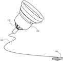
- Fig. 1is a kind of overall structure schematic diagram of the present invention
- Fig. 2is a kind of structural representation of support mechanism of the present invention
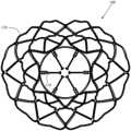
- Fig. 3is the top view of Fig. 2;
- Fig. 4is a kind of structural representation of inner layer support of the present invention.
- Figure 5is a top view of Figure 4.
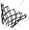
- Fig. 6is a kind of structural schematic diagram of outer layer stent of the present invention.
- Figure 7is a top view of Figure 6;
- Fig. 8is a schematic structural view of the leaflet mechanism of the present invention.
- Fig. 9is a schematic structural view of a single leaflet of the present invention.
- Figure 10is a schematic structural view of the clip of the present invention.
- Fig. 11is a schematic diagram of the relative positions of the clip and the leaflet of the present invention.
- Fig. 12is a schematic diagram of a part of the outer suture film of the present invention.
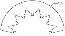
- Fig. 13is another structural schematic diagram of the outer suture film of the present invention.
- Figure 14is a schematic structural view of the inner suture film of the present invention.
- Fig. 15is a schematic structural view of connecting sutured membranes
- Fig. 16is a schematic diagram of an application of the present invention.
- a transcatheter implanted mitral valve deviceincludes a stent mechanism 100 , a leaflet mechanism 200 , a suturing membrane 300 , a traction rope 400 and an anchor 500 .
- the stent mechanism 100includes an inner stent 110 and an outer stent 120 , both of which are connected by sutures through suture holes in the inner bending structure with the same bending angle.
- Both the inner stent 110 and the outer stent 120are compressible mesh structures made of self-expanding materials or memory alloys, such as nickel-titanium alloys.
- the inner stent 110sequentially includes a pulling part 111 , a first connecting part 112 and a guiding part 113 from the proximal end to the distal end.
- the proximal end of the traction part 111is constricted.
- the proximal end of the traction part 111protrudes from the proximal end of the outer support 120 .
- the distal end of the traction part 111is provided with a stent suture hole 1112 for connecting with the outer stent 120 .
- a proximal end of the first connecting portion 112is connected to a distal end of the pulling portion 111 .
- the distal end of the first connecting portion 112is a hollow columnar structure and is connected with the leaflet mechanism 200.
- a leaflet suture hole 1121is provided at the distal end of the first connecting portion 112 for connecting with the leaflet mechanism 200 .
- the proximal end of the guide portion 113is connected to the distal end of the first connecting portion 112 , and the guide portion 113 extends distally along the axial direction of the inner stent 110 .
- a membrane suture hole 1131is provided at the distal end of the guide part 113 for suturing the suture membrane of the guide part.
- the guide part 113is an optional structure, and the guide part 113 can facilitate the crimping and holding of the delivery money of the mitral valve device.
- the inner stent 110can be surrounded and connected by a plurality of Y-shaped stents to obtain a stable stent structure.
- the outer stent 120sequentially includes a second connecting portion 121 , a supporting portion 122 , a fitting portion 123 and a condensation portion 124 from the proximal end to the distal end.
- the proximal end of the second connecting part 121is folded inward, and the proximal end of the second connecting part 121 is protruded by the proximal end of the traction part. end connection.
- the proximal end of the second connecting portion 121is folded inward through an inward bending structure, and the bending angle of the inward bending structure is the same as that of the distal end of the traction portion 111 in FIG. 4 . , so that the second connecting portion 121 and the traction portion 111 are completely attached, and the outer layer stent 120 and the inner layer stent 110 are fixed by sutures between the bracket suture holes 1211 and the bracket suture holes 1112 .
- the bending angleis preferably greater than or equal to 10°.
- the supporting part 122is connected to the distal end of the second connecting part 121, and the supporting part 122 has a hollow columnar structure, preferably a D-shaped cross-section, so as to match the native mitral valve annulus.
- the inside of the support part 122is provided with the first connecting part 112 overhead, and the chord length of the cross section of the support part 122 passing through the center point is larger than the maximum outer diameter of the first connecting part 112 .
- other parts of the inner support 110are suspended inside the outer support 120 , that is, there is no direct contact with the outer support 120 .
- the angle between one side of the longitudinal section of the support portion 122 and the central axis of the inner bracket 110is 5°-15°, that is, as shown in FIG. 2 , the inner bracket 110 is not completely located in the middle of the outer bracket 120 .
- the fitting portion 123is connected to the distal end of the support portion 122, and the fitting portion 123 is a circular truncated structure expanding from the proximal end to the distal end.
- the minimum inner diameter of the fitting portion 123is greater than the maximum outer diameter of the first connecting portion 112, so as Other parts of the inner support 110 except the traction part 111 are suspended in the outer support 120 .
- the included angle a between the generatrix of the bonding portion 123 and the central axis of the bonding portion 123is not less than 20°.
- the fitting portion 123is provided at the distal end of the outer stent to fit more closely to the upper part of the atrium wall without bearing pressure, which can effectively prevent paravalvular leakage.
- the condensation part 124is connected to the distal end of the fitting part 123, and the distal end of the condensation part 124 is folded inward, and the height of the distal end of the condensation part 124 is higher than that of the inner layer stent 110, so that the inner layer stent 110 is folded outside layer bracket 120.
- the included angle b between the gathering surface at the distal end of the condensation part 124 and the generatrix of the bonding part 123is not less than 15°.
- the leaflet mechanism 200is located in the inner stent 110 .
- the leaflet mechanism 200includes several leaflets 210, which are sequentially connected to form a valve body whose outer circumference is a ring structure.
- the valve bodyis fixedly connected to the inner side wall of the first connecting part 112, and the middle part of the valve body can be unidirectional. Opening and closing.
- the leaflet mechanism 200preferably includes three independent leaflets 210 , which form a ring-shaped valve body with a function similar to that of a "one-way valve".
- Each leaflet 210includes a leaflet tail 211 , a sealing strip 212 and a fixing piece 213 .
- the outer side of the leaflet tail 211is a protruding structure, and the outer edge of the protruding structure is connected with the inner side wall of the inner stent 110 .
- the sealing strip 212has a bent structure, the outer side of the sealing strip 212 is connected to the inner side of the leaflet tail 211, the side where the inner side of the sealing strip 212 is located is perpendicular to the plane where the leaflet tail 211 is located, and the other two opposite sides of the sealing strip 212 are respectively set There is a fixed end 2121 , and the fixed end 2121 is folded and wrapped with the clip 214 to form a fixing part 213 , which is fixedly connected with the first connecting part 112 through the fixing part 213 . As shown in FIG.
- the valve leaflet 210in the unbent state of the sealing strip 212 , and the fixed ends 2121 are formed by extending outward from the left and right sides of the sealing strip 212 .
- the thickness of the clip 214is preferably 0.1 mm-0.5 mm, and the clip 214 is provided with at least one clip suture hole 2141, through the clip suture hole 2141, the fixed end 2121 is sutured and wrapped around the clip Sheet 214.
- two adjacent valve leaflets 210are sequentially connected to form a valve body through the fixing member 213 through the clip suture hole 2141 with sutures, and the inner side ends of the sealing strips 212 in the two adjacent valve leaflets 210 are in contact to realize The middle part of the valve body can be opened and closed in one direction.
- the leaflet mechanism 200is fixedly connected to the first connecting part 112 by the fixing part 213, it is also connected and fixed with the leaflet suturing hole 1121 on the first connecting part 112 through the clip suturing hole 2141 with suture thread.
- the leaflet mechanism 200is fixed in the inner stent 110 along the direction of blood flow.
- the mitral valve device designed by the present inventionis designed as a plurality of leaflets 210, and the plurality of leaflets 210 are fixed by clips 214 to form a fixture 213, and then
- the method of suturing into the inner stent 110enhances the strength and stability of the axial leaflet 210 of the leaflet mechanism 200, changes the point contact between the leaflet 210 and the inner stent 110 into a line contact, and reduces blood pressure.
- the pulling force of the local leaflet 210, especially the distal leaflet 210makes the structure more stable.
- the way of longitudinal stitchingensures its "one-way valve" function and effectively improves its bearing capacity against reverse pressure.
- the suture film 300wraps the stent mechanism 100 , and the stent mechanism 100 is connected with the leaflet mechanism 200 through the suture film 300 .
- the suture film 300is designed to effectively promote endothelialization.
- the suture film 300includes an outer suture film, an inner suture film, a connection suture film, a leaflet suture film, and a guide part suture film.
- the outer suture membraneis fixed on the outside of the outer stent 120 , and the outer suture membrane of the present invention can be divided into an upper outer suture membrane 311 and a lower outer suture membrane 312 according to the specific structure of the outer stent 120 .
- the structure of the upper outer suture film 311is shown in FIG. 12 , and the upper outer suture film 311 can be sutured to the upper part of the outer stent 120 such as the outer side of the bonding part 123 and the condensation part 124 .
- the structure of the lower outer suturing membrane 312is shown in FIG. 13 .
- the lower outer suturing membrane 312can be sutured to the lower part of the outer stent 120 such as the outside of the second connecting portion 121 and the support portion 122, and the suturing hole 1211 of the stent is sutured with sutures.
- the inner suturing membraneis fixed on the inner side of the inner layer stent 110 and the inner side of the outer suturing membrane.
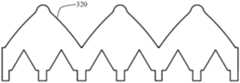
- a structure of an inner suturing membrane 320, the proximal end of the inner suturing membrane 320is in a zigzag structure, and the inner suturing membrane 320 can be sutured through the bracket suture hole 1112, the leaflet suture hole 1121 and the membrane suture hole 1131
- the threadis sutured inside the inner layer stent 110 .
- the connecting suture membraneis connected to the distal ends of the outer suture membrane and the inner suture membrane.
- a connecting suture film 330can connect the distal ends of the outer suture film and the inner suture film through the suture hole 1131 and the suture thread at the distal end, so that all the suture films 300 form a closed whole together.
- the leaflet suture membraneis fixed on the outer edge of the leaflet tail 211 , and the valve leaflet tail 211 is connected to the inner side wall of the inner stent 110 through the suturing and fixed connection of the leaflet suture membrane and the inner suture membrane through sutures.
- the outer edge of the leaflet tail 211is covered with a leaflet suture membrane 330 , and the leaflet suture membrane 330 and the inner suture membrane 320 are fixedly connected by suturing.
- the proximal end of the suture film of the guide parthas a zigzag structure, the suture film of the guide part is arranged on the outer surface of the guide part 113, and the distal end of the suture film of the guide part is sutured outside the distal end of the inner layer stent 110 through the suture hole 1131 and the suture thread.
- the proximal end of the suture film of the guide partis sutured to the proximal outer surface of the inner stent 110 through the leaflet suture hole 1121 and the stent suture hole 1112 and the suture thread.
- the zigzag structure of the suture film of the guide partwraps the suture hole 1112 on the first connecting part 112 and the bracket.
- one end of the traction rope 400is fixedly connected to the traction suture hole 1111 of the traction part 111 .
- the other end of the pulling rope 400is connected to the anchor 500 .
- the traction rope 400is composed of single or multiple ropes, and the traction rope 400 is fixed on the traction suture hole 1111 near the traction part 111 of the inner layer stent 110 by means of winding and suture suture, and makes the inner layer stent 110 proximal end Converging into a compact structure, the total diameter is less than or equal to 2 mm.
- the anchor piece 500has a through hole, allowing the traction rope 400 to pass through freely without locking, and the side of the anchor piece 500 facing away from the apex of the heart is provided with a fixing device, and the traction rope can be locked by means of suture, binding or mechanical restraint when necessary 400, so that it cannot move in the through hole, the diameter of the anchor 500 is preferably 10 mm-30 mm, and the thickness is preferably 0.1 mm-5 mm.
- the outer stent 120 of the mitral valve device covered with a suture membrane 300is fixedly connected to the atrium wall, and the mitral valve device is fixed on the apex of the heart by an anchor 500 .
Landscapes
- Health & Medical Sciences (AREA)
- Cardiology (AREA)
- Engineering & Computer Science (AREA)
- Biomedical Technology (AREA)
- Heart & Thoracic Surgery (AREA)
- Transplantation (AREA)
- Oral & Maxillofacial Surgery (AREA)
- Vascular Medicine (AREA)
- Life Sciences & Earth Sciences (AREA)
- Animal Behavior & Ethology (AREA)
- General Health & Medical Sciences (AREA)
- Public Health (AREA)
- Veterinary Medicine (AREA)
- Prostheses (AREA)
Abstract
Description
Translated fromChinese本发明属于医疗器械技术领域,具体涉及一种二尖瓣瓣膜装置。The invention belongs to the technical field of medical devices, and in particular relates to a mitral valve device.
二尖瓣位于左心房与左心室之间,如同一个单向阀门,保证血液由左心房向左心室方向流动。正常的二尖瓣关闭时,两个瓣叶处在同一个平面且对合密切,能够完全阻挡心室血液向心房回流。但当二尖瓣复合体结构发生损伤或心脏发生损伤时,就会引发二尖瓣反流现象的发生。The mitral valve is located between the left atrium and the left ventricle, like a one-way valve, ensuring blood flow from the left atrium to the left ventricle. When the normal mitral valve is closed, the two valve leaflets are in the same plane and close together, which can completely block the backflow of ventricular blood to the atrium. However, when the structure of the mitral valve complex is damaged or the heart is damaged, mitral regurgitation occurs.
目前通过手术治疗二尖瓣反流的方式主要有外科开胸手术和内科微创手术两种。外科开胸手术由于手术创伤大、风险高以及术后长期而昂贵的康复治疗,使大量患者不愿接受该种治疗方式,而经导管心脏瓣膜治疗术的内科微创手术为医生提供了一种创伤更小、并发症少、术后康复快的新型治疗方法。中国发明专利申请号:202011439539.9,发明名称:一种二尖瓣瓣膜装置及使用方法,公开了一种二尖瓣瓣膜装置及使用方法,该专利通过改进外层支架的形状、结构,很好的解决了瓣膜周漏的问题,但是使用该二尖瓣瓣膜装置进行临床实验时发现,在心脏抖动的过程中,仍然会存在二尖瓣反流的现象。这种反流现象的主要原因是由于内层支架和外层支架在受心脏挤压的支撑部处作为连接点,心脏挤压过程中,内层支架也会发生形变,原本配合完好的瓣叶在形变的影响下可能出现闭合不严的情况,从而导致反流现象的发生。At present, there are two main methods of surgical treatment of mitral regurgitation: surgical thoracotomy and minimally invasive medical surgery. Due to the large surgical trauma, high risk and long-term and expensive postoperative rehabilitation of surgical thoracotomy, a large number of patients are reluctant to accept this kind of treatment, while the minimally invasive surgery of transcatheter heart valve therapy provides doctors with a A new treatment method with less trauma, fewer complications, and faster postoperative recovery. Chinese invention patent application number: 202011439539.9, invention name: a mitral valve device and its use method, which discloses a mitral valve device and its use method. The problem of paravalvular leakage is solved, but when the mitral valve device is used for clinical experiments, it is found that mitral valve regurgitation still exists during the process of heart shaking. The main reason for this reflux phenomenon is that the inner stent and the outer stent serve as the connection point at the support part that is squeezed by the heart. During the heart extrusion process, the inner stent will also be deformed, and the valve leaflets that were originally in good condition will be deformed. Under the influence of deformation, there may be lax closure, which leads to the occurrence of reflux.
发明内容Contents of the invention
本发明针对现有的二尖瓣瓣膜装置由于结构的缺陷存在二尖瓣反流的现象的技术问题,目的在于提供一种经导管植入的二尖瓣瓣膜装置。The present invention aims at the technical problem that existing mitral valve devices have mitral valve regurgitation due to structural defects, and aims to provide a mitral valve device implanted through a catheter.
一种经导管植入的二尖瓣瓣膜装置,包括:A transcatheter implanted mitral valve device comprising:
一支架机构,具有一外层支架、与所述外层支架连接的内层支架;A bracket mechanism, having an outer bracket and an inner bracket connected to the outer bracket;
一瓣叶机构,位于所述内层支架内;a leaflet mechanism located within the inner stent;
所述内层支架自近端向远端依次包括:The inner layer stent includes sequentially from the proximal end to the distal end:
一牵引部,近端呈收束状;a traction part, the proximal end is constricted;
一第一连接部,呈中空柱状结构且与所述瓣叶机构连接,近端与所述牵引部连接;A first connecting part, which is a hollow columnar structure and is connected to the leaflet mechanism, and its proximal end is connected to the traction part;
所述外层支架自近端向远端依次包括:The outer layer stent includes in turn from the proximal end to the distal end:
一第二连接部,与所述牵引部的远端连接,近端向内部收拢,所述第二连接部的近端被所述牵引部的近端伸出;A second connecting part, connected to the distal end of the pulling part, the proximal end is folded inward, and the proximal end of the second connecting part is protruded by the proximal end of the pulling part;
一支撑部,呈中空类柱状结构,内部架空设置有所述第一连接部。A supporting part is a hollow column-like structure, and the first connecting part is arranged overhead.
本发明通过第一连接部的远端与其内侧的瓣叶机构实现连接,实现内层支架装载瓣叶的目的。外层支架的支撑部用于挤压心房壁,并与心房壁固定连接。外层支架和内层支架之间通过第二连接部和牵引部的远端实现连接,且将外层支架的支撑部和内层支架的第一连接部之间采用架空结构,在外层支架受挤压时,内层支架的第一连接部不发生形变,连接在第一连接部内的瓣叶机构能保持密封状态,有效避免了心脏运动对瓣叶的影响。The present invention realizes the connection between the distal end of the first connecting part and the leaflet mechanism inside, so as to achieve the purpose of loading the leaflets on the inner stent. The support portion of the outer stent is used to squeeze the atrium wall and be fixedly connected with the atrium wall. The connection between the outer stent and the inner stent is realized through the second connecting part and the distal end of the traction part, and an overhead structure is adopted between the supporting part of the outer stent and the first connecting part of the inner stent, and when the outer stent is subjected to When squeezed, the first connecting portion of the inner stent does not deform, and the leaflet mechanism connected in the first connecting portion can maintain a sealed state, effectively avoiding the influence of heart movement on the leaflet.
所述支撑部的纵截面的一侧边与所述内层支架的中心轴的夹角为5°-15°。The included angle between one side of the longitudinal section of the support portion and the central axis of the inner support is 5°-15°.
所述支撑部的横截面优选为D字型结构,以配合原生二尖瓣瓣环。The cross-section of the supporting part is preferably a D-shaped structure, so as to match the native mitral valve annulus.
所述支撑部的横截面上经过中心点的弦长大于所述第一连接部的最大外径。The chord length passing through the central point of the cross section of the support part is greater than the maximum outer diameter of the first connecting part.
所述第二连接部的近端通过向内弯折结构实现向内部收拢,所述向内弯折结构的弯折角度与所述牵引部远端的弯折角度相同。The proximal end of the second connecting part is folded inward through an inward bending structure, and the bending angle of the inward bending structure is the same as that of the distal end of the traction part.
所述外层支架自近端向远端还包括:The outer stent also includes from the proximal end to the distal end:
一贴合部,近端与所述支撑部的远端连接,自近端向远端外扩的圆台结构,最小内径大于所述第一连接部的最大外径;A fitting part, the proximal end of which is connected to the distal end of the support part, a circular frustum structure expanding from the proximal end to the distal end, the smallest inner diameter is greater than the largest outer diameter of the first connecting part;
一缩合部,近端与所述贴合部的远端连接,远端向内部收拢。A constriction part, the proximal end is connected with the far end of the fitting part, and the far end is folded inward.
所述贴合部的母线与所述贴合部的中心轴之间的夹角不小于20°。The included angle between the generatrix of the bonding part and the central axis of the bonding part is not less than 20°.
所述缩合部远端的收拢面与所述贴合部的母线之间的夹角不小于15°。The angle between the gathering surface at the distal end of the constriction part and the generatrix of the bonding part is not less than 15°.
所述内层支架还包括:The inner support also includes:
一导向部,与所述第一连接部的远端连接,沿所述内层支架的轴向向远端延伸。A guide part is connected with the distal end of the first connecting part and extends distally along the axial direction of the inner stent.
所述外层支架和所述内层支架均为可压缩网状结构,均采用自膨胀材质或记忆合金制成,如镍钛合金等。The outer stent and the inner stent both have a compressible mesh structure and are made of self-expanding material or memory alloy, such as nickel-titanium alloy.
所述瓣叶机构包括若干片瓣叶,若干片所述瓣叶依次连接形成外圆周为圆环结构的瓣膜体,所述瓣膜体与所述第一连接部的内侧壁固定连接,所述瓣膜体的中部可单向开合。The leaflet mechanism includes several leaflets, which are sequentially connected to form a valve body whose outer circumference is a ring structure, the valve body is fixedly connected to the inner side wall of the first connecting part, and the valve body The middle part of the body can be opened and closed in one direction.
每片所述瓣叶均包括:Each of said leaflets includes:
一瓣叶尾部,外侧为突出结构,所述突出结构的外侧边缘与所述内层支架的内侧壁连接;A leaflet tail, the outer side is a protruding structure, and the outer edge of the protruding structure is connected with the inner side wall of the inner stent;
一密封条,弯折结构,外侧连接所述瓣叶尾部的内侧,内侧所在的侧面与所述瓣叶尾部所在的平面垂直,所述密封条的另两个对侧面分别设置有固定端,所述固定端翻折 并包裹有夹片后形成固定件,通过所述固定件与所述第一连接部固定连接;A sealing strip, with a bent structure, the outer side is connected to the inner side of the tail of the leaflet, the side where the inner side is located is perpendicular to the plane where the tail of the leaflet is located, and the other two opposite sides of the sealing strip are respectively provided with fixed ends, so The fixed end is folded and wrapped with a clip to form a fixed part, and the fixed part is fixedly connected with the first connecting part through the fixed part;
相邻两个所述瓣叶通过所述固定件依次连接形成所述瓣膜体,相邻两个所述瓣叶中的密封条内侧面端部接触以实现所述瓣膜体的中部可单向开合。The two adjacent valve leaflets are sequentially connected by the fixing member to form the valve body, and the inner side surfaces of the sealing strips in the two adjacent valve leaflets are in contact so that the middle part of the valve body can be opened in one direction. combine.
所述二尖瓣瓣膜装置还包括:The mitral valve device also includes:
缝合膜,包裹所述支架机构,并与所述瓣叶机构连接。A membrane is sutured, wrapping the stent mechanism, and connecting with the leaflet mechanism.
所述缝合膜包括:The sutured membrane includes:
一外缝合膜,固定于所述外层支架外侧;an outer suture membrane, fixed on the outer side of the outer stent;
一内缝合膜,固定于所述内层支架内侧及所述外缝合膜内侧;an inner suture membrane fixed on the inner side of the inner stent and the inner side of the outer suture membrane;
一连接缝合膜,与所述外缝合膜和所述内缝合膜的远端相连;a connecting suture membrane connected to the distal ends of the outer suture membrane and the inner suture membrane;
一瓣叶缝合膜,固定于所述瓣叶尾部的外侧边缘,由所述瓣叶缝合膜和所述内缝合膜的固定连接实现所述瓣叶尾部和所述内层支架的内侧壁连接。A leaflet suture membrane is fixed on the outer edge of the leaflet tail, and the leaflet tail is connected to the inner side wall of the inner stent through the fixed connection of the leaflet suture membrane and the inner suture membrane.
所述牵引部的远端和所述第二连接部上均设有相互配合的支架缝合孔,所述内层支架和所述外层支架通过所述支架缝合孔连接;The distal end of the traction part and the second connecting part are provided with bracket suture holes that cooperate with each other, and the inner bracket and the outer bracket are connected through the bracket suture holes;
所述第一连接部的上设有瓣叶缝合孔,所述内层支架和所述瓣叶机构通过瓣叶缝合孔连接。A leaflet suture hole is provided on the first connecting part, and the inner support and the leaflet mechanism are connected through the leaflet suture hole.
所述导向部的远端设有覆膜缝合孔,所述导向部的外表面设有导向部缝合膜,所述导向部缝合膜的近端呈锯齿结构,所述锯齿结构将所述第一连接部上的瓣叶缝合孔和所述牵引部上的支架缝合孔均包裹在内。The far end of the guide part is provided with a covering suture hole, the outer surface of the guide part is provided with a guide part suture film, and the proximal end of the guide part suture film is in a sawtooth structure, and the sawtooth structure divides the first Both the leaflet suture hole on the connection part and the bracket suture hole on the traction part are covered.
所述牵引部的近端设有牵引缝合孔;The proximal end of the traction part is provided with a traction suture hole;
所述二尖瓣瓣膜装置还包括:The mitral valve device also includes:
一牵引绳,一端与所述牵引部的所述牵引缝合孔固定连接;A traction rope, one end of which is fixedly connected to the traction suture hole of the traction part;
一锚固件,与所述牵引绳的另一端连接,由所述锚固件将所述二尖瓣瓣膜装置固定在心尖上。An anchor is connected with the other end of the traction rope, and the mitral valve device is fixed on the apex of the heart by the anchor.
本发明的积极进步效果在于:本发明采用经导管植入的二尖瓣瓣膜装置,具有如下显著优点:The positive and progressive effect of the present invention is that the present invention adopts the mitral valve device implanted through the catheter, which has the following significant advantages:
1、内层支架和外层支架之间为架空结构,有效避免了心脏运动对瓣叶的影响;1. There is an overhead structure between the inner stent and the outer stent, which effectively avoids the influence of heart movement on the leaflets;
2、外层支架的上部设置贴合部,在不承受压力的前提下更贴合心房壁的上部,防止瓣周漏。2. The upper part of the outer stent is equipped with a fitting part, which fits the upper part of the atrium wall better without bearing pressure, so as to prevent paravalvular leakage.
3、多片独立瓣叶构成的瓣叶机构具备类似“单向阀”功能的膜瓣结构,结构更为稳定可靠;3. The leaflet mechanism composed of multiple independent leaflets has a valve structure similar to a "one-way valve" function, and the structure is more stable and reliable;
4、缝合膜包裹支架机构,可有效促进内皮化。4. The suture membrane wraps the stent mechanism, which can effectively promote endothelialization.
图1为本发明的一种整体结构示意图;Fig. 1 is a kind of overall structure schematic diagram of the present invention;
图2为本发明支架机构的一种结构示意图;Fig. 2 is a kind of structural representation of support mechanism of the present invention;
图3为图2的俯视图;Fig. 3 is the top view of Fig. 2;
图4为本发明内层支架的一种结构示意图;Fig. 4 is a kind of structural representation of inner layer support of the present invention;
图5为图4的俯视图;Figure 5 is a top view of Figure 4;
图6为本发明外层支架的一种结构示意图;Fig. 6 is a kind of structural schematic diagram of outer layer stent of the present invention;
图7为图6的俯视图;Figure 7 is a top view of Figure 6;
图8为本发明瓣叶机构的一种结构示意图;Fig. 8 is a schematic structural view of the leaflet mechanism of the present invention;
图9为本发明单片瓣叶的一种结构示意图;Fig. 9 is a schematic structural view of a single leaflet of the present invention;
图10为本发明夹片的一种结构示意图;Figure 10 is a schematic structural view of the clip of the present invention;
图11为本发明夹片和瓣叶的相对位置示意图;Fig. 11 is a schematic diagram of the relative positions of the clip and the leaflet of the present invention;
图12为本发明外缝合膜的一部分结构示意图;Fig. 12 is a schematic diagram of a part of the outer suture film of the present invention;
图13为本发明外缝合膜的另一部分结构示意图;Fig. 13 is another structural schematic diagram of the outer suture film of the present invention;
图14为本发明内缝合膜的一种结构示意图;Figure 14 is a schematic structural view of the inner suture film of the present invention;
图15为连接缝合膜的一种结构示意图;Fig. 15 is a schematic structural view of connecting sutured membranes;
图16为本发明的一种应用示意图。Fig. 16 is a schematic diagram of an application of the present invention.
为了使本发明实现的技术手段、创作特征、达成目的与功效易于明白了解,下面结合具体图示进一步阐述本发明。In order to make the technical means, creative features, goals and effects achieved by the present invention easy to understand, the present invention will be further described below in conjunction with specific diagrams.
参照图1至16,一种经导管植入的二尖瓣瓣膜装置,包括支架机构100、瓣叶机构200、缝合膜300、牵引绳400和锚固件500。Referring to FIGS. 1 to 16 , a transcatheter implanted mitral valve device includes a
参照图2和图3,支架机构100包括内层支架110和外层支架120,两者通过弯折角度相同的内弯折结构上的支架缝合孔经缝合线进行连接。内层支架110和外层支架120均为可压缩网状结构,均采用自膨胀材质或记忆合金制成,如镍钛合金等。Referring to FIG. 2 and FIG. 3 , the
参照图4和图5,内层支架110自近端向远端依次包括牵引部111、第一连接部112和导向部113。Referring to FIG. 4 and FIG. 5 , the
牵引部111的近端呈收束状,牵引部111的近端伸出于外层支架120的近端,牵引部111的近端设置有牵引缝合孔1111,用于与牵引绳400固定连接。牵引部111的远端设有支架缝合孔1112,用于与外层支架120连接。The proximal end of the
第一连接部112的近端与牵引部111的远端连接。第一连接部112的远端呈中空柱 状结构且与瓣叶机构200连接。在第一连接部112的远端设置有瓣叶缝合孔1121,用于与瓣叶机构200连接。A proximal end of the first connecting
导向部113的近端与第一连接部112的远端连接,导向部113沿内层支架110的轴向向远端延伸。在导向部113的远端设有覆膜缝合孔1131,用于缝合导向部缝合膜。导向部113是一种可选结构,导向部113可方便二尖瓣瓣膜装置输送钱的压握。内层支架110的远端设置导向部113后,如图4所示,内层支架110可通过多个Y字型支架环绕连接得到稳定的支架结构。The proximal end of the
参照图6和图7,外层支架120自近端向远端依次包括第二连接部121、支撑部122、贴合部123和缩合部124。Referring to FIG. 6 and FIG. 7 , the
第二连接部121的近端向内部收拢,第二连接部121的近端被牵引部的近端伸出,第二连接部121上设置有支架缝合孔1211,用于与牵引部111的远端连接。如图6中所示,第二连接部121的近端通过向内弯折结构实现向内部收拢,向内弯折结构的弯折角度与图4中的牵引部111远端的弯折角度相同,以便于第二连接部121和牵引部111完全贴合,通过支架缝合孔1211和支架缝合孔1112之间经缝合线缝合实现外层支架120和内层支架110的固定。该弯折角度优选大于等于10°。The proximal end of the second connecting
支撑部122与第二连接部121的远端连接,支撑部122呈中空类柱状结构,优选其横截面为D字型结构,以配合原生二尖瓣瓣环。支撑部122的内部架空设置有第一连接部112,支撑部122的横截面上经过中心点的弦长大于第一连接部112的最大外径。优选除了第二连接部121和牵引部111具有连接,内层支架110的其他部件均架空于外层支架120内,即与外层支架120无直接接触。支撑部122的纵截面的一侧边与内层支架110的中心轴的夹角为5°-15°,即如图2所示,内层支架110并不是完全位于外层支架120的中部。The supporting
贴合部123与支撑部122的远端连接,贴合部123为自近端向远端外扩的圆台结构,贴合部123的最小内径大于第一连接部112的最大外径,以便于内层支架110除牵引部111外的其他部分均架空于外层支架120内。如图6中所示,贴合部123的母线与贴合部123的中心轴之间的夹角a不小于20°。在外层支架的远端设置贴合部123,在不承受压力的前提下更贴合心房壁的上部,可有效防止瓣周漏。The
缩合部124与贴合部123的远端连接,缩合部124远端向内部收拢,缩合部124的远端高度高于内层支架110的远端高度,以便于将内层支架110架空收拢在外层支架120内。缩合部124远端的收拢面与贴合部123的母线之间的夹角b不小于15°。The
参照图8,瓣叶机构200位于内层支架110内。瓣叶机构200包括若干片瓣叶210,若干片瓣叶210依次连接形成外圆周为圆环结构的瓣膜体,瓣膜体与第一连接部112的 内侧壁固定连接,瓣膜体的中部可单向开合。如图8中所示,瓣叶机构200优选包括三片独立的瓣叶210,通过三片瓣叶210围成了圆环结构的瓣膜体,具备类似“单向阀”功能。Referring to FIG. 8 , the
每片瓣叶210均包括瓣叶尾部211、密封条212和固定件213。瓣叶尾部211的外侧为突出结构,突出结构的外侧边缘与内层支架110的内侧壁连接。密封条212为弯折结构,密封条212的外侧连接瓣叶尾部211的内侧,密封条212的内侧所在的侧面与瓣叶尾部211所在的平面垂直,密封条212的另两个对侧面分别设置有固定端2121,固定端2121翻折并包裹有夹片214后形成固定件213,通过固定件213与第一连接部112固定连接。如图9所示,为密封条212未弯折状态下的瓣叶210,在密封条212的左右两侧面向外延伸形成固定端2121。如图10所示,夹片214的厚度优选0.1毫米-0.5毫米,夹片214上设置有至少一个夹片缝合孔2141,经夹片缝合孔2141将固定端2121经缝合线缝合并包裹住夹片214。Each
参照图11,相邻两个瓣叶210通过固定件213经夹片缝合孔2141用缝合线缝合依次连接形成瓣膜体,相邻两个瓣叶210中的密封条212内侧面端部接触以实现瓣膜体的中部可单向开合。瓣叶机构200在通过固定件213与第一连接部112固定连接时,也经夹片缝合孔2141与第一连接部112上的瓣叶缝合孔1121用缝合线缝合实现连接固定,固定时,将瓣叶机构200沿血液流动方向固定于内层支架110内。虽然虽然原生瓣为二尖瓣,但考虑到结构的稳定性,本发明设计的二尖瓣瓣膜装置设计成多片瓣叶210,多片瓣叶210由夹片214固定形成固定件213,再进行缝合到内层支架110内的方式,增强了瓣叶机构200的轴向瓣叶210的强度和稳定性,将瓣叶210与内层支架110的点接触变成了线接触,减小血流通过时,局部瓣叶210,特别是远端瓣叶210的拉力,使结构更加稳固。纵向缝合的方式保证了其“单向阀”功能的同时有效提高了其对反向压力的承载能力。Referring to FIG. 11 , two
缝合膜300包裹支架机构100,支架机构100通过缝合膜300与瓣叶机构200连接。缝合膜300的设计可有效促进内皮化。The
参照图12至图15,缝合膜300包括外缝合膜、内缝合膜、连接缝合膜、瓣叶缝合膜和导向部缝合膜。Referring to FIGS. 12 to 15 , the
外缝合膜固定于外层支架120外侧,本发明的外缝合膜可以根据外层支架120的具体结构分为上部外缝合膜311和下部外缝合膜312。上部外缝合膜311的结构如图12所示,上部外缝合膜311可缝合于外层支架120的上部如贴合部123和缩合部124的外侧。下部外缝合膜312的结构如图13所示,下部外缝合膜312可缝合于外层支架120的下部如第二连接部121、支撑部122的外侧,将支架缝合孔1211用缝合线缝合。The outer suture membrane is fixed on the outside of the
内缝合膜固定于内层支架110内侧及外缝合膜内侧。如图14所示的一种内缝合膜320结构,该内缝合膜320的近端呈锯齿结构,内缝合膜320可以通过支架缝合孔1112、瓣叶缝合孔1121和覆膜缝合孔1131经缝合线缝合于内层支架110内侧。The inner suturing membrane is fixed on the inner side of the
连接缝合膜与外缝合膜和内缝合膜的远端相连。如图15所示的一种连接缝合膜330,可以通过远端的覆膜缝合孔1131及缝合线将外缝合膜和内缝合膜的远端相连,使所有缝合膜300共同形成一个闭合整体。The connecting suture membrane is connected to the distal ends of the outer suture membrane and the inner suture membrane. As shown in FIG. 15 , a connecting
瓣叶缝合膜固定于瓣叶尾部211的外侧边缘,由瓣叶缝合膜和内缝合膜经缝合线的缝合固定连接实现瓣叶尾部211述内层支架110的内侧壁连接。如图8和图9所示,瓣叶尾部211的外侧边缘包覆有瓣叶缝合膜330,瓣叶缝合膜330和内缝合膜320经缝合固定连接。The leaflet suture membrane is fixed on the outer edge of the
导向部缝合膜的近端呈锯齿结构,导向部缝合膜设置在导向部113的外表面,导向部缝合膜的远端经覆膜缝合孔1131及缝合线缝合于内层支架110的远端外表面,导向部缝合膜的近端经瓣叶缝合孔1121和支架缝合孔1112及缝合线缝合于内层支架110的近端外表面。导向部缝合膜的锯齿结构将第一连接部112上的和支架缝合孔1112均包裹在内。The proximal end of the suture film of the guide part has a zigzag structure, the suture film of the guide part is arranged on the outer surface of the
参照图1,牵引绳400的一端与牵引部111的牵引缝合孔1111固定连接。牵引绳400的另一端连接锚固件500。Referring to FIG. 1 , one end of the
牵引绳400由单根或多根绳索组成,牵引绳400通过缠绕及缝合线缝合的方式固定于内层支架110的牵引部111近端的牵引缝合孔1111上,并使内层支架110近端收束为紧密结构,总直径小于等于2毫米。The
锚固件500带有通孔,允许牵引绳400在未锁定情况下自由穿行,锚定件500背对心尖一侧设有固定装置,在需要时可通过缝合、捆绑或机械约束等方式锁定牵引绳400,使其无法在通孔内窜动,锚定件500直径优选为10毫米-30毫米,厚度优选为0.1毫米-5毫米。The
如图16所示,二尖瓣瓣膜装置的包覆有缝合膜300的外层支架120与心房壁固定连接,由锚固件500将二尖瓣瓣膜装置固定在心尖上。As shown in FIG. 16 , the
以上显示和描述了本发明的基本原理、主要特征和本发明的优点。本行业的技术人员应该了解,本发明不受上述实施例的限制,上述实施例和说明书中描述的只是说明本发明的原理,在不脱离本发明精神和范围的前提下,本发明还会有各种变化和改进,这些变化和改进都落入要求保护的本发明范围内。本发明要求保护范围由所附的权利要求书及其等效物界定。The basic principles, main features and advantages of the present invention have been shown and described above. Those skilled in the industry should understand that the present invention is not limited by the above-mentioned embodiments, and what described in the above-mentioned embodiments and the description only illustrates the principles of the present invention, and the present invention will also have other functions without departing from the spirit and scope of the present invention. Variations and improvements are possible, which fall within the scope of the claimed invention. The protection scope of the present invention is defined by the appended claims and their equivalents.
Claims (10)
Translated fromChineseApplications Claiming Priority (2)
| Application Number | Priority Date | Filing Date | Title |
|---|---|---|---|
| CN202111135239.6ACN113730034B (en) | 2021-09-27 | 2021-09-27 | Transcatheter Mitral Valve Devices |
| CN202111135239.6 | 2021-09-27 |
Publications (1)
| Publication Number | Publication Date |
|---|---|
| WO2023045326A1true WO2023045326A1 (en) | 2023-03-30 |
Family
ID=78741300
Family Applications (1)
| Application Number | Title | Priority Date | Filing Date |
|---|---|---|---|
| PCT/CN2022/089409CeasedWO2023045326A1 (en) | 2021-09-27 | 2022-04-26 | Transcatheter implantable mitral valve device |
Country Status (2)
| Country | Link |
|---|---|
| CN (1) | CN113730034B (en) |
| WO (1) | WO2023045326A1 (en) |
Families Citing this family (7)
| Publication number | Priority date | Publication date | Assignee | Title |
|---|---|---|---|---|
| CN113730034B (en)* | 2021-09-27 | 2023-07-21 | 启晨(上海)医疗器械有限公司 | Transcatheter Mitral Valve Devices |
| CN115517821A (en)* | 2022-05-13 | 2022-12-27 | 科凯(南通)生命科学有限公司 | Transapical mitral valve replacement device |
| CN115517820A (en)* | 2022-05-13 | 2022-12-27 | 科凯(南通)生命科学有限公司 | Transapical mitral valve replacement device |
| CN117297831B (en)* | 2022-06-21 | 2024-05-07 | 启晨(上海)医疗器械有限公司 | Mitral valve device |
| CN115414155B (en)* | 2022-09-05 | 2025-06-24 | 科凯(南通)生命科学有限公司 | Transapical mitral valve replacement with balloon-expandable valve device |
| CN117796963A (en)* | 2022-09-26 | 2024-04-02 | 南京圣德医疗科技有限公司 | A valve implantation device assisted by a cardiac isolation device |
| CN116269942B (en)* | 2023-05-16 | 2023-10-27 | 乐普(北京)医疗器械股份有限公司 | Artificial heart valve |
Citations (9)
| Publication number | Priority date | Publication date | Assignee | Title |
|---|---|---|---|---|
| US20140379076A1 (en)* | 2013-06-25 | 2014-12-25 | Tendyne Holdings, Inc. | Halo Wire Fluid Seal Device for Prosthetic Mitral Valves |
| US20150142103A1 (en)* | 2012-07-28 | 2015-05-21 | Tendyne Holdings, Inc. | Multi-component designs for heart valve retrieval device, sealing structures and stent assembly |
| CN106175987A (en)* | 2016-08-31 | 2016-12-07 | 上海纽脉医疗科技有限公司 | Cardiac valve prosthesis |
| CN208725961U (en)* | 2017-09-25 | 2019-04-12 | 先健科技(深圳)有限公司 | heart valve |
| CN212395131U (en)* | 2020-07-15 | 2021-01-26 | 上海臻亿医疗科技有限公司 | Artificial heart valve |
| CN112438827A (en)* | 2020-12-10 | 2021-03-05 | 启晨(上海)医疗器械有限公司 | Mitral valve device and using method |
| CN212662031U (en)* | 2020-09-15 | 2021-03-09 | 杭州德晋医疗科技有限公司 | Artificial heart valve stent, artificial heart valve and artificial heart valve replacement system |
| CN113599023A (en)* | 2021-07-16 | 2021-11-05 | 复旦大学附属中山医院 | Intervention type artificial heart valve |
| CN113730034A (en)* | 2021-09-27 | 2021-12-03 | 启晨(上海)医疗器械有限公司 | Transcatheter implanted mitral valve device |
Family Cites Families (6)
| Publication number | Priority date | Publication date | Assignee | Title |
|---|---|---|---|---|
| US7776084B2 (en)* | 2005-07-13 | 2010-08-17 | Edwards Lifesciences Corporation | Prosthetic mitral heart valve having a contoured sewing ring |
| BR122014006918B1 (en)* | 2010-03-23 | 2020-09-29 | Edwards Lifesciences Corporation. | METHOD FOR PREPARING BIOPROTETIC TISSUE MEMBRANE MATERIAL |
| JP6219377B2 (en)* | 2012-05-20 | 2017-10-25 | テル ハショマー メディカル リサーチ インフラストラクチャー アンド サーヴィシーズ リミテッド | Artificial mitral valve |
| CA2975361A1 (en)* | 2015-02-02 | 2016-08-11 | Symetis Sa | Stent seals and method of production |
| FR3043907A1 (en)* | 2015-11-23 | 2017-05-26 | Alain Dibie | ASSEMBLY FOR REPLACING THE TRICUSPID ATRIO-VENTRICULAR VALVE |
| CN111772878B (en)* | 2020-07-15 | 2025-02-11 | 上海臻亿医疗科技有限公司 | A heart valve prosthesis |
- 2021
- 2021-09-27CNCN202111135239.6Apatent/CN113730034B/enactiveActive
- 2022
- 2022-04-26WOPCT/CN2022/089409patent/WO2023045326A1/ennot_activeCeased
Patent Citations (9)
| Publication number | Priority date | Publication date | Assignee | Title |
|---|---|---|---|---|
| US20150142103A1 (en)* | 2012-07-28 | 2015-05-21 | Tendyne Holdings, Inc. | Multi-component designs for heart valve retrieval device, sealing structures and stent assembly |
| US20140379076A1 (en)* | 2013-06-25 | 2014-12-25 | Tendyne Holdings, Inc. | Halo Wire Fluid Seal Device for Prosthetic Mitral Valves |
| CN106175987A (en)* | 2016-08-31 | 2016-12-07 | 上海纽脉医疗科技有限公司 | Cardiac valve prosthesis |
| CN208725961U (en)* | 2017-09-25 | 2019-04-12 | 先健科技(深圳)有限公司 | heart valve |
| CN212395131U (en)* | 2020-07-15 | 2021-01-26 | 上海臻亿医疗科技有限公司 | Artificial heart valve |
| CN212662031U (en)* | 2020-09-15 | 2021-03-09 | 杭州德晋医疗科技有限公司 | Artificial heart valve stent, artificial heart valve and artificial heart valve replacement system |
| CN112438827A (en)* | 2020-12-10 | 2021-03-05 | 启晨(上海)医疗器械有限公司 | Mitral valve device and using method |
| CN113599023A (en)* | 2021-07-16 | 2021-11-05 | 复旦大学附属中山医院 | Intervention type artificial heart valve |
| CN113730034A (en)* | 2021-09-27 | 2021-12-03 | 启晨(上海)医疗器械有限公司 | Transcatheter implanted mitral valve device |
Also Published As
| Publication number | Publication date |
|---|---|
| CN113730034A (en) | 2021-12-03 |
| CN113730034B (en) | 2023-07-21 |
Similar Documents
| Publication | Publication Date | Title |
|---|---|---|
| CN113730034B (en) | Transcatheter Mitral Valve Devices | |
| US12427015B2 (en) | Prosthetic valve and deployment system | |
| JP6637409B2 (en) | Catheter guide replacement valve device and method | |
| CN107744416B (en) | Apparatus and method for implanting a replacement heart valve | |
| EP3689298A1 (en) | Heart valve prosthesis | |
| US12274614B2 (en) | Valve stent and prosthetic valve apparatus | |
| CN105852916A (en) | Mitral valve flexible closing plate blocking body implanted through cardiac apex and implantation method | |
| CN111643223B (en) | Grafts to repair or replace the heart's own valves | |
| CN113303947A (en) | Anchoring device for heart valve | |
| CN112754732A (en) | Interventional artificial heart valve and medical device | |
| CN115153961A (en) | A valve support and valve prosthesis comprising the valve support | |
| WO2023020301A1 (en) | Mitral valve membrane repairing stent | |
| CN218075337U (en) | Mitral Valve Stent Mechanism | |
| CN216777297U (en) | mitral valve stent | |
| CN114271995B (en) | Interventional prosthetic valve by apex anchoring | |
| CN215130906U (en) | Anchoring device, replacement device and replacement system for heart valve | |
| CN218075336U (en) | Mitral valve stent mechanism | |
| WO2024067809A1 (en) | Artificial heart valve | |
| JP2025531543A (en) | artificial heart valves | |
| CN113813083B (en) | Tricuspid valve clamping device | |
| US20240148495A1 (en) | Anchoring device for heart valve | |
| CN117297831A (en) | Mitral valve device | |
| CN209966664U (en) | Device for reducing the area of the mitral annulus opening | |
| CN116807688B (en) | Valve stent and valve device | |
| CN117297832B (en) | Mitral valve device |
Legal Events
| Date | Code | Title | Description |
|---|---|---|---|
| 121 | Ep: the epo has been informed by wipo that ep was designated in this application | Ref document number:22871389 Country of ref document:EP Kind code of ref document:A1 | |
| NENP | Non-entry into the national phase | Ref country code:DE | |
| 122 | Ep: pct application non-entry in european phase | Ref document number:22871389 Country of ref document:EP Kind code of ref document:A1 | |
| 122 | Ep: pct application non-entry in european phase | Ref document number:22871389 Country of ref document:EP Kind code of ref document:A1 | |
| 32PN | Ep: public notification in the ep bulletin as address of the adressee cannot be established | Free format text:NOTING OF LOSS OF RIGHTS PURSUANT TO RULE 112(1) EPC (EPO FORM 1205A DATED 11.02.2025) |