WO2023045142A1 - Microfluidic device - Google Patents
Microfluidic deviceDownload PDFInfo
- Publication number
- WO2023045142A1 WO2023045142A1PCT/CN2021/139639CN2021139639WWO2023045142A1WO 2023045142 A1WO2023045142 A1WO 2023045142A1CN 2021139639 WCN2021139639 WCN 2021139639WWO 2023045142 A1WO2023045142 A1WO 2023045142A1
- Authority
- WO
- WIPO (PCT)
- Prior art keywords
- electrode
- electrodes
- substrate
- sub
- plane
- Prior art date
- Legal status (The legal status is an assumption and is not a legal conclusion. Google has not performed a legal analysis and makes no representation as to the accuracy of the status listed.)
- Ceased
Links
Images


Classifications
- B—PERFORMING OPERATIONS; TRANSPORTING
- B01—PHYSICAL OR CHEMICAL PROCESSES OR APPARATUS IN GENERAL
- B01L—CHEMICAL OR PHYSICAL LABORATORY APPARATUS FOR GENERAL USE
- B01L3/00—Containers or dishes for laboratory use, e.g. laboratory glassware; Droppers
- B01L3/50—Containers for the purpose of retaining a material to be analysed, e.g. test tubes
- B01L3/502—Containers for the purpose of retaining a material to be analysed, e.g. test tubes with fluid transport, e.g. in multi-compartment structures
- B01L3/5027—Containers for the purpose of retaining a material to be analysed, e.g. test tubes with fluid transport, e.g. in multi-compartment structures by integrated microfluidic structures, i.e. dimensions of channels and chambers are such that surface tension forces are important, e.g. lab-on-a-chip
- B01L3/502769—Containers for the purpose of retaining a material to be analysed, e.g. test tubes with fluid transport, e.g. in multi-compartment structures by integrated microfluidic structures, i.e. dimensions of channels and chambers are such that surface tension forces are important, e.g. lab-on-a-chip characterised by multiphase flow arrangements
- B01L3/502784—Containers for the purpose of retaining a material to be analysed, e.g. test tubes with fluid transport, e.g. in multi-compartment structures by integrated microfluidic structures, i.e. dimensions of channels and chambers are such that surface tension forces are important, e.g. lab-on-a-chip characterised by multiphase flow arrangements specially adapted for droplet or plug flow, e.g. digital microfluidics
- B01L3/502792—Containers for the purpose of retaining a material to be analysed, e.g. test tubes with fluid transport, e.g. in multi-compartment structures by integrated microfluidic structures, i.e. dimensions of channels and chambers are such that surface tension forces are important, e.g. lab-on-a-chip characterised by multiphase flow arrangements specially adapted for droplet or plug flow, e.g. digital microfluidics for moving individual droplets on a plate, e.g. by locally altering surface tension
- B—PERFORMING OPERATIONS; TRANSPORTING
- B01—PHYSICAL OR CHEMICAL PROCESSES OR APPARATUS IN GENERAL
- B01L—CHEMICAL OR PHYSICAL LABORATORY APPARATUS FOR GENERAL USE
- B01L3/00—Containers or dishes for laboratory use, e.g. laboratory glassware; Droppers
- B01L3/50—Containers for the purpose of retaining a material to be analysed, e.g. test tubes
- B01L3/502—Containers for the purpose of retaining a material to be analysed, e.g. test tubes with fluid transport, e.g. in multi-compartment structures
- B01L3/5027—Containers for the purpose of retaining a material to be analysed, e.g. test tubes with fluid transport, e.g. in multi-compartment structures by integrated microfluidic structures, i.e. dimensions of channels and chambers are such that surface tension forces are important, e.g. lab-on-a-chip
- B01L3/502715—Containers for the purpose of retaining a material to be analysed, e.g. test tubes with fluid transport, e.g. in multi-compartment structures by integrated microfluidic structures, i.e. dimensions of channels and chambers are such that surface tension forces are important, e.g. lab-on-a-chip characterised by interfacing components, e.g. fluidic, electrical, optical or mechanical interfaces
- B—PERFORMING OPERATIONS; TRANSPORTING
- B01—PHYSICAL OR CHEMICAL PROCESSES OR APPARATUS IN GENERAL
- B01L—CHEMICAL OR PHYSICAL LABORATORY APPARATUS FOR GENERAL USE
- B01L3/00—Containers or dishes for laboratory use, e.g. laboratory glassware; Droppers
- B01L3/50—Containers for the purpose of retaining a material to be analysed, e.g. test tubes
- B01L3/502—Containers for the purpose of retaining a material to be analysed, e.g. test tubes with fluid transport, e.g. in multi-compartment structures
- B01L3/5027—Containers for the purpose of retaining a material to be analysed, e.g. test tubes with fluid transport, e.g. in multi-compartment structures by integrated microfluidic structures, i.e. dimensions of channels and chambers are such that surface tension forces are important, e.g. lab-on-a-chip
- B01L3/50273—Containers for the purpose of retaining a material to be analysed, e.g. test tubes with fluid transport, e.g. in multi-compartment structures by integrated microfluidic structures, i.e. dimensions of channels and chambers are such that surface tension forces are important, e.g. lab-on-a-chip characterised by the means or forces applied to move the fluids
- B—PERFORMING OPERATIONS; TRANSPORTING
- B01—PHYSICAL OR CHEMICAL PROCESSES OR APPARATUS IN GENERAL
- B01L—CHEMICAL OR PHYSICAL LABORATORY APPARATUS FOR GENERAL USE
- B01L2200/00—Solutions for specific problems relating to chemical or physical laboratory apparatus
- B01L2200/14—Process control and prevention of errors
- B01L2200/143—Quality control, feedback systems
- B—PERFORMING OPERATIONS; TRANSPORTING
- B01—PHYSICAL OR CHEMICAL PROCESSES OR APPARATUS IN GENERAL
- B01L—CHEMICAL OR PHYSICAL LABORATORY APPARATUS FOR GENERAL USE
- B01L2300/00—Additional constructional details
- B01L2300/04—Closures and closing means
- B01L2300/046—Function or devices integrated in the closure
- B01L2300/047—Additional chamber, reservoir
- B—PERFORMING OPERATIONS; TRANSPORTING
- B01—PHYSICAL OR CHEMICAL PROCESSES OR APPARATUS IN GENERAL
- B01L—CHEMICAL OR PHYSICAL LABORATORY APPARATUS FOR GENERAL USE
- B01L2300/00—Additional constructional details
- B01L2300/06—Auxiliary integrated devices, integrated components
- B01L2300/0627—Sensor or part of a sensor is integrated
- B01L2300/0645—Electrodes
- B—PERFORMING OPERATIONS; TRANSPORTING
- B01—PHYSICAL OR CHEMICAL PROCESSES OR APPARATUS IN GENERAL
- B01L—CHEMICAL OR PHYSICAL LABORATORY APPARATUS FOR GENERAL USE
- B01L2400/00—Moving or stopping fluids
- B01L2400/04—Moving fluids with specific forces or mechanical means
- B01L2400/0403—Moving fluids with specific forces or mechanical means specific forces
- B01L2400/0415—Moving fluids with specific forces or mechanical means specific forces electrical forces, e.g. electrokinetic
- B01L2400/0427—Electrowetting
Definitions
- the present applicationrelates to the field of microfluidic technology, for example, to a microfluidic device.
- the principle of electrowettingis usually used to control the flow position of the liquid in the microfluidic device by setting at least one substrate voltage.
- the process of driving the automatic movement of liquid dropletsthere will be changes in the size of the liquid droplets and the residue of liquid droplets on the electrode, which will affect the accuracy of subsequent tests; position for precise control.
- the driving electrodesare all set completely.
- the driving electrodesWhen detecting the droplet position through the sensing electrodes arranged on one side of the driving electrodes, only the droplets at a specific position of the driving electrodes can be detected.
- the liquid droplets in the gap between two adjacent driving electrodesare detected, and the liquid droplets not in this position cannot be detected, the detection accuracy is limited, and the droplet size and a small amount of liquid droplets remaining in the orthographic projection of the driving electrodes cannot be measured.
- the present applicationprovides a microfluidic device to improve the problem in the related art that the size change of the droplet cannot be detected and the accurate position of the droplet within the orthographic projection of the electrode surface.
- the present applicationprovides a microfluidic device, comprising a first substrate and a second substrate oppositely arranged, a cavity is formed between the first substrate and the second substrate, and the cavity is configured to accommodate liquid;
- the first substrateincludes a plurality of driving electrodes and a plurality of first electrodes, the plurality of driving electrodes are located on a side of the plurality of first electrodes facing the second substrate, and the plurality of driving electrodes are arranged in an array;
- At least one driving electrodeincludes at least one opening, and the opening penetrates the driving electrode where the opening is located along a direction perpendicular to the plane where the first substrate is located; the orthographic projection of at least one first electrode on the plane where the first substrate is located covers at least one opening Orthographic projection on the plane where the first substrate is located;
- the second substrateincludes at least one second electrode, and the orthographic projection of the second electrode on the plane of the first substrate at least partially overlaps the orthographic projection of the first electrode on the plane of the first substrate.
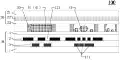
- FIG. 1is a schematic partial cross-sectional view of a microfluidic device provided in an embodiment of the present application
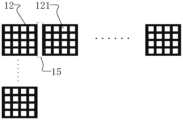
- FIG. 2is a top view of a driving electrode provided in an embodiment of the present application.
- FIG. 3is a schematic partial cross-sectional view of another microfluidic device provided in the embodiment of the present application.
- FIG. 4is a schematic partial cross-sectional view of another microfluidic device provided in the embodiment of the present application.
- FIG. 5is a schematic partial cross-sectional view of another microfluidic device provided in the embodiment of the present application.
- Figure 6is a top perspective view provided by the embodiment of the present application.
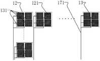
- FIG. 7is another top perspective view provided by the embodiment of the present application.
- FIG. 8is another top perspective view provided by the embodiment of the present application.
- FIG. 9is another top perspective view provided by the embodiment of the present application.
- FIG. 10is another top perspective view provided by the embodiment of the present application.
- FIG. 11is a schematic partial cross-sectional view of another microfluidic device provided in the embodiment of the present application.
- FIG. 12is a top view of another driving electrode provided by the embodiment of the present application.
- any valuesshould be construed as exemplary only, and not as limitations. Therefore, other instances of the exemplary embodiment may have different values.
- the driving electrodesare all set completely.
- the driving electrodesWhen detecting the droplet position through the sensing electrodes arranged on one side of the driving electrodes, only the droplets at a specific position of the driving electrodes can be detected.
- the liquid droplets in the gap between two adjacent driving electrodesare detected, and the liquid droplets not in this position cannot be detected, the detection accuracy is limited, and the droplet size and a small amount of liquid droplets remaining in the orthographic projection of the driving electrodes cannot be measured.
- the present applicationprovides a microfluidic device to improve the problem in the related art that the size change of the droplet cannot be detected and the accurate position of the droplet within the orthographic projection of the electrode surface.
- FIG. 1is a partial cross-sectional schematic diagram of a microfluidic device provided in the embodiment of the present application
- Figure 2is a top view of a driving electrode provided in the embodiment of the present application
- a microfluidic device 100is provided, including a first substrate 10 and a second substrate 20 oppositely arranged, a cavity 30 is formed between the first substrate 10 and the second substrate 20, and the cavity 30 is configured to accommodate a liquid 40
- a substrate 10includes a plurality of driving electrodes 12 and a plurality of first electrodes 13, the plurality of driving electrodes 12 are located on the side of the plurality of first electrodes 13 facing the second substrate 20, and the plurality of driving electrodes 12 are arranged in an array
- at least one driving The electrode 12includes at least one opening 121, and the opening 121 penetrates the driving electrode 12 where the opening 121 is located along a direction perpendicular to the plane where the first substrate 10 is located; the orthographic projection of at least one first electrode 13 on the plane where the first substrate 10
- the present applicationprovides a microfluidic device 100, the microfluidic device 100 includes a first substrate 10 and a second substrate oppositely arranged 20 , a cavity 30 is formed between the first substrate 10 and the second substrate 20 , and the cavity 30 is configured to accommodate a liquid 40 that can be driven to flow.
- the cavity 30 of the microfluidic device 100is usually formed by at least one channel, or may also include at least one branch channel.
- FIG. 1only shows a schematic diagram of a driving electrode 12 and a first electrode 13, which is used to illustrate the microfluidic device 100 proposed in this application, but it does not mean that only one microfluidic device 100 will be It includes a drive electrode 12 and a first electrode 13 .
- the present applicationprovides an arrangement method of the first substrate 10.
- the first substrate 10may include a plurality of driving electrodes 12 and a plurality of first electrodes 13, wherein the plurality of driving electrodes 12 are arranged in the direction of the plurality of first electrodes 13.
- One side of the second substrate 20, that is, the drive electrode 12is arranged closer to the cavity 30 than the first electrode 13; wherein, as shown in FIG. 2, when the number of multiple drive electrodes 12 is relatively large, A plurality of driving electrodes 12 can be arranged in an array; by applying voltage signals to the driving electrodes 12 , they are used to drive the movement of the liquid 40 in the cavity 30 .
- the present applicationprovides openings 121 on part or all of the driving electrodes 12, and the openings 121 are formed by penetrating the driving electrodes 12 in a direction perpendicular to the plane where the first substrate 10 is located, that is, opening at least One through hole forms at least one opening portion 121 .
- the orthographic projection of the first electrode 13 on the plane of the first substrate 10can cover the orthographic projection of the opening 121 on the plane of the first substrate 10 .
- the present applicationprovides an arrangement method of the second substrate 20.
- the second substrate 20includes at least one second electrode 22, and the orthographic projection of the second electrode 22 on the plane where the first substrate 10 is located is the same The orthographic projections of the plane where the substrate 10 is located overlap at least partially.
- the cavity 30 containing the liquid 40is located between the first electrode 13 and the second electrode 22. When a voltage signal is applied to the first electrode 13 and the second electrode 22, the liquid droplet 41 remaining in the cavity 30 is connected with the first electrode 13 and the second electrode 22.
- a capacitanceis formed between the electrodes 13, and the capacitance is connected to the capacitance formed between the droplet 41 and the second electrode 22; by detecting the capacitance and capacitance change between the first electrode 13 and the second electrode 22, it can be judged whether the position is The liquid droplet 41 exists, and the size of the liquid droplet 41 is detected at the same time.
- it is detected that the capacitance of a placeis different from the capacitance of the normal area without the droplet 41 , it means that the residual droplet 41 exists in the area corresponding to the capacitance.
- the present applicationdoes not limit the size of the driving electrode 12, nor does it limit the number and size of the openings 121 provided on a driving electrode 12, as long as the openings 121 provided can be set so that the first electrode 13 and the second electrode 22 Capacitors are formed between them to detect the size and position of the residual liquid droplet 41 in the cavity 30 .
- the plurality of driving electrodes 12 shown in FIG. 2 , each driving electrode 12 including 16 openings 121 arranged in an arrayis only an optional embodiment provided by this application, and is not used for setting the openings 121 Quantity, shape, arrangement, etc. are limited.
- the first substrate 10also includes a glass substrate 11, the first electrode 13 is formed on the surface of the glass substrate 11, and the first substrate 10 also includes a hydrophobic layer 14 arranged adjacent to the liquid 40; the second substrate 20 also includes an oppositely arranged The hydrophobic layer 23 and the glass cover plate 21, a cavity 30 is provided between the two opposing hydrophobic layers 14 and 23 to accommodate the liquid 40.
- FIG. 3is a schematic partial cross-sectional view of another microfluidic device provided in the embodiment of the present application. Please refer to FIG. The electrodes 131 are provided on the same layer.
- the first electrode 13 located in the first substrate 10includes a plurality of first sub-electrodes 131, all the first sub-electrodes 131 can be selected to be arranged in the same film structure, that is, all the first sub-electrodes 131 are the same. layer settings.
- At least part of the first sub-electrode 131can form a capacitance between the opening 121 and the correspondingly arranged second electrode 22, and the capacitance includes the overlapping area of the first sub-electrode 131 and its orthographic projection position on the plane where the first substrate 10 is located.
- the capacitance formed between the droplets 41also includes the capacitance formed between the droplets 41 and the second electrode 22.
- FIG. 4is a schematic partial cross-sectional view of another microfluidic device provided in the embodiment of the present application. Please refer to FIG.
- the sub-electrode 131 and the plurality of second sub-electrodes 132are of different layers and are insulated.
- the first electrode 13may also include a plurality of second sub-electrodes 132, here
- the plurality of second sub-electrodes 132can be arranged in the same film layer, and the plurality of first sub-electrodes 131 and the plurality of second sub-electrodes 132 can be arranged in different layers.
- the applicationsets the insulation between the film layer where the first sub-electrode 131 is located and the film layer where the second sub-electrode 132 is located, so as to avoid the risk of electrical connection between the first sub-electrode 131 and the second sub-electrode 132, and also It is convenient to manufacture the first sub-electrode 131 and the second sub-electrode 132 .
- the orthographic projection of the first sub-electrode 131 on the plane where the first substrate 10 is locatedis the same as that of the second sub-electrode 132 on the plane where the first substrate 10 is located.
- the orthographic projectionsare set so as not to overlap; this setting makes the capacitance formed between the first sub-electrode 131 and the second electrode 22 and the capacitance formed between the second sub-electrode 132 and the second electrode 22 not affect each other.
- the first sub-electrode 131is set as a capacitance formed between the correspondingly set second electrode 22 to detect the liquid that has an overlapping area with the first sub-electrode 131 in the orthographic projection of the plane where the first substrate 10 is located.
- the position and size of the droplet 41; the second sub-electrode 132is set to form a capacitance with the corresponding second electrode 22 to detect the presence of the second sub-electrode 132 in the orthographic projection of the plane where the first substrate 10 is located.
- the position and size of the droplet 41 in the overlapping areais set as a capacitance formed between the correspondingly set second electrode 22 to detect the liquid that has an overlapping area with the first sub-electrode 131 in the orthographic projection of the plane where the first substrate 10 is located.
- each opening 121 on the driving electrode 12 on the plane where the first substrate 10 is locatedwill only be aligned with one first sub-electrode 131 or one second sub-electrode.
- the orthographic projection of 132 on the plane where the first substrate 10 is locatedhas an overlapping area; such setting can make one opening 121 only correspond to one first sub-electrode 131 or one second sub-electrode 132, and the opening 121 on the second A droplet 41 having an overlapping area in the orthographic projection of the plane of the substrate 10 can be accurately positioned.
- the above-mentioned setting methodis only an embodiment provided by this application, and this application is not limited thereto, and users can make corresponding setting adjustments according to actual needs.
- FIG. 5is a schematic partial cross-sectional view of another microfluidic device provided in the embodiment of the present application. Please refer to FIG. 2 and FIG. 5.
- a first For the gap 15the orthographic projection of the first electrode 13 on the plane of the first substrate 10 covers at least part of the orthographic projection of the first gap 15 on the plane of the first substrate 10 .
- the present applicationprovides an alternative embodiment, wherein any two adjacent driving electrodes 12 include a first gap 15, at this time
- the orthographic projection of the first electrode 13 in the first substrate 10 on the plane of the first substrate 10can be set to cover at least part of the orthographic projection of the first gap 15 on the plane of the first substrate 10, so that the first electrode 13 can transmit the first electrode 13
- the capacitance formed between a gap 15 and the correspondingly arranged second electrode 22is used to detect whether there is a droplet 41 in the orthographic projection area of the first gap 15 on the plane where the first substrate 10 is located, and at the same time realize the detection of the droplet by the size of the capacitance. 41 size detection.
- the orthographic projection of the first electrode 13 on the plane where the first substrate 10 is locatednot only has an overlapping area with the orthographic projection of the opening 121 on the plane where the first substrate 10 is located, but the first electrode 13 on the plane where the first substrate 10 is located has an overlapping area.
- the orthographic projection and the orthographic projection of the first gap 15 between the adjacent driving electrodes 12 on the plane where the first substrate 10 is locatedalso have an overlapping area, so that in the cavity 30 of the microfluidic device 100, the opening 121, the second A gap 15 detects the position and size of the droplet 41 having an overlapping area in the orthographic projection area of the plane where the first substrate 10 is located.
- each first One electrode 13is electrically connected to at least one detection signal line 171 , and at least one detection signal line 171 transmits a detection signal to the first electrode 13 .
- the signal line 171is set to be electrically connected to the first electrode 13, so as to transmit the detection signal to the first electrode 13, and drive the first electrode 13 to pass through the opening 121 and/or between the first gap 15 and the corresponding second electrode 22 to generate Capacitance, so as to detect the position and size of the droplet 41 having an overlapping area with the opening 121 and the first gap 15 in the orthographic projection area of the plane where the first substrate 10 is located.
- any first sub-electrode 131is electrically connected to a detection signal line 171; when the first electrode 13 includes first sub-electrodes 131 and second sub-electrodes 132, each first sub-electrode The electrode 131 and each second sub-electrode 132 are electrically connected to a detection signal line 171 .
- the detection of the size and position of the droplet 41 in the designated area of the microfluidic device 100can be realized to avoid waste of resources.
- each first electrode 13is electrically connected to at least one detection signal line 171, that is, part of the first electrodes 13 can be set as required.
- Each first electrode 13 of the first electrode 13is electrically connected to one detection signal line 171, and each first electrode 13 in the set part of the first electrodes 13 is electrically connected to a plurality of detection signal lines 171, so as to realize a mixed arrangement.
- FIG. 8is another top perspective view provided by the embodiment of the present application. Please refer to FIG. 5 and FIG.
- the orthographic projection of the plane where the first substrate 10 is locatedoverlaps, and the multiple first electrodes 13 that overlap the orthographic projection of the same drive electrode 12 on the plane where the first substrate 10 is located are all electrically connected to the same detection signal line 171, and the detection signal
- the wire 171transmits a detection signal to the first electrode 13 .
- the orthographic projection of each driving electrode 12 on the plane where the first substrate 10 is locatedis the same as that of the plurality of first electrodes 13 on the plane where the first substrate 10 is located.
- the orthographic projectionhas an overlapping area; a plurality of first electrodes 13 having an overlapping area with the same driving electrode 12 in the orthographic projection area of the plane where the first substrate 10 is located can be set to be connected to the same detection signal line 171, so The setting can realize the detection of the size of the droplet 41 and the position of the droplet 41 in the specified area in the microfluidic device 100, and the detection can obtain the positive position of the droplet 41 on the plane where the first substrate 10 is located in a certain driving electrode 12.
- the projection areais beneficial to reduce the number of arranging detection signal lines 171 , avoid occupying too much area of the microfluidic device 100 , and increase the number and density of electrodes in the microfluidic device 100 .
- FIG. 9is another top perspective view provided by the embodiment of the present application. Please refer to FIG. 4 and FIG. 9.
- a plurality of first sub-electrodes 131extend along the first direction and are arranged along the second direction.
- a plurality of second sub-electrodes 132extend along the second direction and are arranged along the first direction; the first direction is parallel to the row direction of the array formed by the plurality of driving electrodes 12, and the second direction is parallel to the row direction of the array formed by the plurality of driving electrodes 12.
- the column directionis parallel.
- the present applicationprovides an optional arrangement method that the multiple first sub-electrodes 131 all extend along the first direction and Arranged along the second direction, the plurality of second sub-electrodes 132 extend along the second direction and are arranged along the first direction, wherein the first direction and the second direction are perpendicular to each other.
- the first electrodes 13(the first sub-electrodes 131 and the second sub-electrodes 132) arranged in two layers can be arranged to form row and column mesh wiring respectively, and the driving electrodes 12 of each row/column correspond to the first electrodes 13
- the second electrode 22can detect whether there is a droplet 41 on the row/column, and detect the size of the droplet 41 present in the cavity 30 . After sequentially numbering the first electrodes 13 arranged in the row/column, the detected droplet 41 can be coded to show the location of the droplet 41 in the microfluidic device 100 .
- FIG. 10is another top perspective view provided by the embodiment of the present application. Please refer to FIG. 5 and FIG.
- the signal bus 181 , the first detection signal bus 181simultaneously transmits the first detection signal to the plurality of first sub-electrodes 131 .
- the present applicationprovides an optional embodiment in which the orthographic projection of a row of driving electrodes 12 on the plane of the first substrate 10 is set to overlap with the orthographic projections of a plurality of first sub-electrodes 131 on the plane of the first substrate 10, wherein A plurality of first sub-electrodes 131 that overlap the orthographic projection of a row of driving electrodes 12 on the plane of the first substrate 10 may be set to be electrically connected to the same first detection signal bus 181, that is, the first detection signal bus 181
- the bus 181can simultaneously transmit the first detection signal to the plurality of first sub-electrodes 131 corresponding to the row of driving electrodes 12 .
- the first electrode 13only includes a plurality of first sub-electrodes 131 arranged on the same layer, that is, the detection signal lines 171 that are respectively electrically connected to the plurality of first sub-electrodes 131 corresponding to each row of driving electrodes 12 are connected at the tail end,
- the detection signalsare simultaneously provided through a first detection signal bus 181 .
- the first sub-electrode 131 corresponding to the driving electrode 12 of each rowcan detect whether there is a droplet 41 in the area where the orthographic projection on the row is located, and detect the size of the droplet 41 existing in the cavity 30, and judge the liquid out through the row signal comprehensively.
- the position and corresponding size of the droplet 41are shown accurately to show the detected position of the droplet 41 in the microfluidic device 100 .
- the orthographic projection of a column of driving electrodes 12 on the plane of the first substrate 10overlaps with the orthographic projection of a plurality of second sub-electrodes 132 on the plane of the first substrate 10;
- a plurality of second sub-electrodes 132 overlapped by the orthographic projection of the electrode 12 on the plane where the first substrate 10 is locatedare all electrically connected to the same second detection signal bus 182 , and the second detection signal bus 182 is connected to the plurality of second sub-electrodes 132 At the same time, the second detection signal is transmitted.
- the present applicationprovides an optional embodiment, when the first electrode 13 includes first sub-electrodes 131 and second sub-electrodes 132 arranged in layers, and the first sub-electrodes 131 and second sub-electrodes 132 are arranged in rows and columns When laying out; the present application sets a plurality of first sub-electrodes 131 that overlap with the orthographic projection of a row of driving electrodes 12 on the plane where the first substrate 10 is located, and are electrically connected to the same first detection signal bus 181, and are set to be connected with a row of driving electrodes 12.
- the multiple second sub-electrodes 132 overlapped by the orthographic projection of the electrode 12 on the plane where the first substrate 10 is locatedare all electrically connected to the same second detection signal bus 182.
- the detection signal lines 171 that are electrically connected to the plurality of first sub-electrodes 131 corresponding to the driving electrodes 12 in each roware connected at the tail ends, and a detection signal is provided at the same time through a first detection signal bus 181.
- the driving electrodes 12 of each columnThe detection signal lines 171 to which the corresponding plurality of second sub-electrodes 132 are electrically connected are connected at the tail ends, and a detection signal is simultaneously provided through a second detection signal bus 182 .
- the first electrode 13 corresponding to the driving electrode 12 of each row/columncan detect whether there is a droplet 41 on the row/column, and detect the size of the droplet 41 existing in the cavity 30, and judge it comprehensively through the row/column signal The location and corresponding size of the droplet 41. That is, M+N detection signal buses (M first detection signal buses 181 and N second detection signal buses 182) can be used to detect the droplets 41 on the driving electrodes 12 of the M*N array, thereby accurately showing the The detected position of the droplet 41 in the microfluidic device 100 .
- FIG. 11is a schematic partial cross-sectional view of another microfluidic device provided in the embodiment of the present application. Please refer to FIG. 19 is configured to apply a driving voltage signal to the driving electrodes 12, and different driving voltage signals are applied to adjacent driving electrodes 12 to drive the liquid 40 to move. Only one transistor 19 corresponding to one driving electrode 12 is shown in FIG. 11 .
- a plurality of transistors 19that are electrically connected to the plurality of driving electrodes 12 one by one may also be provided, and the transistors 19 are configured to load a driving voltage signal to the driving electrodes 12, that is, through the transistor 19 is used as a switch to control whether to apply a driving voltage signal to the driving electrode 12 .
- different driving voltage signalscan be applied to the adjacent driving electrodes 12 to drive the movement of the liquid 40 in the microfluidic device 100 through the electric field formed between the adjacent driving electrodes 12 .
- a plurality of transistors 19are located on a side away from the second substrate 20 of the plurality of driving electrodes 12; The orthographic projections of the plane where the first substrate 10 is located are overlapped.
- the present applicationprovides an optional arrangement method, that is, a plurality of transistors 19 are arranged on the side of the plurality of driving electrodes 12 away from the second substrate 20, and the transistors can be selected at this time.
- the orthographic projection of 19 on the plane where the first substrate 10 is locatedoverlaps with the orthographic projection of the driving electrode 12 corresponding to the transistor 19 on the plane where the first substrate 10 is located, that is, at least part of the film layer structure forming the transistor 19 is located on the first substrate 10.
- the orthographic projection of the planecan overlap with the orthographic projection of the driving electrode 12 corresponding to the transistor 19 on the plane where the first substrate 10 is located.
- the transistor 19is arranged under the drive electrode 12, not in the area corresponding to the first gap 15 or the opening 121, so that the drive electrode 12 can shield the parasitic capacitance caused by the transistor 19, thereby effectively improving the liquid droplet 41. positioning accuracy.
- each transistor 19includes a gate 193, a first pole 191 and a second pole 192; the first pole 191 is electrically connected to the drive electrode 12 corresponding to the transistor 19; the first sub-electrode 131 Located on the side of the second sub-electrode 132 facing the second substrate 20 , the gate 193 is disposed on the same layer as the second sub-electrode 132 , and the first pole 191 and the second pole 192 are disposed on the same layer as the first sub-electrode 131 .
- the microfluidic device 100including scanning lines, data lines and transistors 19 can be set to
- the active driving methodis similar to the display panel; each driving electrode 12 is similar to a sub-pixel in the display panel, and the scanning line and the data line are used to realize the scanning, and the active driving of the driving electrode 12 is realized by using the on-off of the transistor 19, wherein , the transistor 19 includes a gate 193, a first pole 191 and a second pole 192 (source and drain), the first pole 191 can be electrically connected to the drive electrode 12, the second pole 192 is electrically connected to the data line, and the gate 193 It is electrically connected with the scan line.
- the transistor 19may be a thin film transistor, for example, a thin film transistor formed by using amorphous silicon material, polysilicon material or metal oxide material as the active layer 194 .
- the present applicationprovides a method for setting the transistor 19.
- the first electrode 13includes the first sub-electrode 131 and the second sub-electrode 132 arranged in layers
- the first sub-electrode 131can be set to be located in the direction of the second sub-electrode 132.
- the gate 193 in the transistor 19is set on the same layer as the second sub-electrode 132
- the first pole 191 and the second pole 192are set on the same layer as the first sub-electrode 131, thereby avoiding damage to the transistor 19 when the transistor 19 is set.
- the increase in the film thickness of the microfluidic device 100is also beneficial to simplify the manufacturing process of the microfluidic device 100 .
- At least part of the second sub-electrode 132is multiplexed as a gate 193
- at least part of the first sub-electrode 131is multiplexed as a first pole 191 and a second pole 192 .
- the present applicationalso provides a An optional embodiment is to reuse at least part of the completed second sub-electrode 132 as the gate 193 of the transistor 19, and reuse at least part of the completed first sub-electrode 131 as the first electrode of the transistor 19. 191 and the second pole 192; this arrangement can not only ensure that the thickness of the film layer of the microfluidic device 100 is not increased, but also can reuse the production process and the fabricated structure of the film layer, which simplifies the microfluidic device. 100's production process.
- any driving electrode 12includes a plurality of openings 121 , and the plurality of openings 121 are evenly distributed.
- any driving electrode 12includes The plurality of openings 121 are evenly distributed, so that the detection effect of the liquid droplets 41 in the area where the driving electrode 12 is located is more uniform and accurate, and avoid the problem that some liquid droplets 41 cannot be detected due to the uneven setting of the openings 121 .
- the applicationcan also set the openings 121 provided on different driving electrodes 12 to be arranged in the same manner, so that the openings 121 in the entire microfluidic device 100 are evenly arranged to enhance the driving force.
- the droplet 41 detection effect in the area where the electrode 12 is locatedis beneficial to simplify the manufacturing process of the opening portion 121 .
- two adjacent rows of openings 121 arranged along the first directionare arranged in a dislocation; direction parallel.
- FIG. 12is a top view of another driving electrode provided by the embodiment of the present application. Please refer to FIG. 12 in conjunction with FIG. oval or triangular.
- the present applicationprovides some optional configuration methods, that is, the orthographic projection of the opening 121 on the plane where the first substrate 10 is located is a rectangle, a circle, an ellipse or a triangle, etc. .
- the present applicationcan choose the shape of the openings 121 to be triangular. Triangles are alternately arranged in this way, so that the number of openings 121 correspondingly arranged on one driving electrode 12 is greater, so that the detection effect of the first electrode 13 and the second electrode 22 on the residual droplet 41 through the openings 121 is better.
- the present applicationdoes not limit that the opening 121 on one driving electrode 12 can only have the same shape, and does not limit the size of the opening 121 .
- the second electrode 22is a planar electrode, a bulk electrode or a strip electrode.
- the present applicationdoes not limit the setting shapes of the driving electrodes 12, the first electrodes 13, and the second electrodes 22.
- the driving electrodes 12, the first electrodes 13, and the second electrodes 22can be arranged as strip electrodes, block electrodes, surface electrodes, etc. As long as it can be ensured that the first electrode 13 and the second electrode 22 can detect the residual liquid droplet 41 in the cavity 30 through the opening 121 opened on the driving electrode 12 .
- the first electrode 13is a touch electrode, and the second electrode 22 is a common electrode; or, the first electrode 13 is a common electrode, and the second electrode 22 is a touch electrode.
- the first electrode 13 providedcan be a touch electrode, such as a touch sensing electrode, which is set to sense the size and position of the residual droplet 41 in the cavity 30;
- the second electrode 22can be a common electrode, which is used to form a capacitance between the opening 121 and the first electrode 13 , and obtain the size and position of at least part of the residual liquid droplet 41 in the cavity 30 through the change of the capacitance.
- the second electrode 22 providedmay be a touch electrode, such as a touch sensing electrode, which is configured to sense the size and position of the residual droplet 41 in the cavity 30;
- the first electrode 13can be a common electrode for forming a capacitance between the opening 121 and the second electrode 22 , and the size and position of the residual droplet 41 in at least part of the cavity 30 can be obtained through the change of the capacitance.
- At least one openingis opened on at least one driving electrode of the first substrate in the microfluidic device, and a first electrode is provided on the side of the first substrate where the driving electrode is away from the second substrate.
- the capacitance change between the opening and the second electrode on the second substratedetects the size and exact position of the droplet existing in the orthographic projection surface of the driving electrode, and realizes the detection of the residual droplet in the microfluidic device.
Landscapes
- Chemical & Material Sciences (AREA)
- Health & Medical Sciences (AREA)
- Dispersion Chemistry (AREA)
- Analytical Chemistry (AREA)
- General Health & Medical Sciences (AREA)
- Hematology (AREA)
- Clinical Laboratory Science (AREA)
- Chemical Kinetics & Catalysis (AREA)
- Physical Or Chemical Processes And Apparatus (AREA)
- Automatic Analysis And Handling Materials Therefor (AREA)
Abstract
Description
Translated fromChinese本申请要求在2021年09月24日提交中国专利局、申请号为202111121736.0的中国专利申请的优先权,该申请的全部内容通过引用结合在本申请中。This application claims the priority of a Chinese patent application with application number 202111121736.0 filed with the China Patent Office on September 24, 2021, the entire content of which is incorporated herein by reference.
本申请涉及微流控技术领域,例如,涉及一种微流控装置。The present application relates to the field of microfluidic technology, for example, to a microfluidic device.
相关技术中,通常利用电润湿的原理,通过设置至少一个基板电压控制微流控装置中液体的流动位置。驱动液滴自动化移动的过程中,会发生液滴大小变化及电极上液滴的残留,影响后续试验精度;因此,在液体自动化移动的过程中,需要实时反馈液体、以及液体的残留液滴的位置,以便于精准控制。In the related art, the principle of electrowetting is usually used to control the flow position of the liquid in the microfluidic device by setting at least one substrate voltage. In the process of driving the automatic movement of liquid droplets, there will be changes in the size of the liquid droplets and the residue of liquid droplets on the electrode, which will affect the accuracy of subsequent tests; position for precise control.
相关技术中,驱动电极都是完整设置的,通过位于驱动电极一侧设置的感应电极进行液滴位置检测时,只能对驱动电极特定位置的液滴进行检测,例如只能对至少部分位于相邻两个驱动电极之间间隙内的液滴进行检测,对不在该位置的液滴无法进行检测,检测准确度有限,且无法测量液滴大小和少量残余在驱动电极正投影内的液滴。In the related art, the driving electrodes are all set completely. When detecting the droplet position through the sensing electrodes arranged on one side of the driving electrodes, only the droplets at a specific position of the driving electrodes can be detected. The liquid droplets in the gap between two adjacent driving electrodes are detected, and the liquid droplets not in this position cannot be detected, the detection accuracy is limited, and the droplet size and a small amount of liquid droplets remaining in the orthographic projection of the driving electrodes cannot be measured.
发明内容Contents of the invention
本申请提供了一种微流控装置,用以改善相关技术中,无法对液滴的大小变化、液滴在电极表面正投影内的准确位置进行检测的问题。The present application provides a microfluidic device to improve the problem in the related art that the size change of the droplet cannot be detected and the accurate position of the droplet within the orthographic projection of the electrode surface.
本申请提供一种微流控装置,包括相对设置的第一基板和第二基板,第一基板和第二基板之间形成空腔,空腔设置为容纳液体;The present application provides a microfluidic device, comprising a first substrate and a second substrate oppositely arranged, a cavity is formed between the first substrate and the second substrate, and the cavity is configured to accommodate liquid;
第一基板包括多个驱动电极、多个第一电极,多个驱动电极位于多个第一电极朝向第二基板一侧,多个驱动电极呈阵列排布;The first substrate includes a plurality of driving electrodes and a plurality of first electrodes, the plurality of driving electrodes are located on a side of the plurality of first electrodes facing the second substrate, and the plurality of driving electrodes are arranged in an array;
至少一个驱动电极上包括至少一个开口部,开口部沿垂直于第一基板所在平面的方向贯穿开口部所在的驱动电极;至少一个第一电极在第一基板所在平面的正投影至少覆盖一个开口部在第一基板所在平面的正投影;At least one driving electrode includes at least one opening, and the opening penetrates the driving electrode where the opening is located along a direction perpendicular to the plane where the first substrate is located; the orthographic projection of at least one first electrode on the plane where the first substrate is located covers at least one opening Orthographic projection on the plane where the first substrate is located;
第二基板包括至少一个第二电极,第二电极在第一基板所在平面的正投影与第一电极在第一基板所在平面的正投影至少部分交叠。The second substrate includes at least one second electrode, and the orthographic projection of the second electrode on the plane of the first substrate at least partially overlaps the orthographic projection of the first electrode on the plane of the first substrate.
图1所示为本申请实施例提供的一种微流控装置的局部截面示意图;FIG. 1 is a schematic partial cross-sectional view of a microfluidic device provided in an embodiment of the present application;
图2所示为本申请实施例提供的一种驱动电极的俯视图;FIG. 2 is a top view of a driving electrode provided in an embodiment of the present application;
图3所示为本申请实施例提供的另一种微流控装置的局部截面示意图;FIG. 3 is a schematic partial cross-sectional view of another microfluidic device provided in the embodiment of the present application;
图4所示为本申请实施例提供的另一种微流控装置的局部截面示意图;FIG. 4 is a schematic partial cross-sectional view of another microfluidic device provided in the embodiment of the present application;
图5所示为本申请实施例提供的另一种微流控装置的局部截面示意图;FIG. 5 is a schematic partial cross-sectional view of another microfluidic device provided in the embodiment of the present application;
图6所示为本申请实施例提供的一种俯视透视图;Figure 6 is a top perspective view provided by the embodiment of the present application;
图7所示为本申请实施例提供的另一种俯视透视图;FIG. 7 is another top perspective view provided by the embodiment of the present application;
图8所示为本申请实施例提供的另一种俯视透视图;FIG. 8 is another top perspective view provided by the embodiment of the present application;
图9所示为本申请实施例提供的另一种俯视透视图;FIG. 9 is another top perspective view provided by the embodiment of the present application;
图10所示为本申请实施例提供的另一种俯视透视图;FIG. 10 is another top perspective view provided by the embodiment of the present application;
图11所示为本申请实施例提供的另一种微流控装置的局部截面示意图;FIG. 11 is a schematic partial cross-sectional view of another microfluidic device provided in the embodiment of the present application;
图12所示为本申请实施例提供的另一种驱动电极的俯视图。FIG. 12 is a top view of another driving electrode provided by the embodiment of the present application.
参照附图来描述本申请的多种示例性实施例。除非另外说明,否则在这些实施例中阐述的部件和步骤的相对布置、数字表达式和数值不限制本申请的范围。Various exemplary embodiments of the present application are described with reference to the accompanying drawings. The relative arrangements of components and steps, numerical expressions and numerical values set forth in these embodiments do not limit the scope of the present application unless otherwise stated.
以下对至少一个示例性实施例的描述实际上仅仅是说明性的,决不作为对本申请及其应用或使用的任何限制。The following description of at least one exemplary embodiment is merely illustrative in nature and in no way serves as any limitation of the application, its application or uses.
对于相关领域普通技术人员已知的技术、方法和设备可能不作讨论,但在适当情况下,所述技术、方法和设备应当被视为说明书的一部分。Techniques, methods and devices known to those of ordinary skill in the relevant art may not be discussed, but where appropriate, such techniques, methods and devices should be considered part of the description.
在这里示出和讨论的所有例子中,任何值应被解释为仅仅是示例性的,而不是作为限制。因此,示例性实施例的其它例子可以具有不同的值。In all examples shown and discussed herein, any values should be construed as exemplary only, and not as limitations. Therefore, other instances of the exemplary embodiment may have different values.
相似的标号和字母在下面的附图中表示类似项,因此,一旦一项在一个附图中被定义,则在随后的附图中不需要对其进行讨论。Like numbers and letters denote similar items in the following figures, so once an item is defined in one figure, it need not be discussed in subsequent figures.
相关技术中,驱动电极都是完整设置的,通过位于驱动电极一侧设置的感应电极进行液滴位置检测时,只能对驱动电极特定位置的液滴进行检测,例如只能对至少部分位于相邻两个驱动电极之间间隙内的液滴进行检测,对不在该位置的液滴无法进行检测,检测准确度有限,且无法测量液滴大小和少量残余在驱动电极正投影内的液滴。In the related art, the driving electrodes are all set completely. When detecting the droplet position through the sensing electrodes arranged on one side of the driving electrodes, only the droplets at a specific position of the driving electrodes can be detected. The liquid droplets in the gap between two adjacent driving electrodes are detected, and the liquid droplets not in this position cannot be detected, the detection accuracy is limited, and the droplet size and a small amount of liquid droplets remaining in the orthographic projection of the driving electrodes cannot be measured.
本申请提供了一种微流控装置,用以改善相关技术中,无法对液滴的大小变化、液滴在电极表面正投影内的准确位置进行检测的问题。The present application provides a microfluidic device to improve the problem in the related art that the size change of the droplet cannot be detected and the accurate position of the droplet within the orthographic projection of the electrode surface.
图1所示为本申请实施例提供的一种微流控装置的局部截面示意图,图2所示为本申请实施例提供的一种驱动电极的俯视图,请参照图1和图2,本申请提供了一种微流控装置100,包括相对设置的第一基板10和第二基板20,第一基板10和第二基板20之间形成空腔30,空腔30设置为容纳液体40;第一基板10包括多个驱动电极12、多个第一电极13,多个驱动电极12位于多个第一电极13朝向第二基板20一侧,多个驱动电极12呈阵列排布;至少一个驱动电极12上包括至少一个开口部121,开口部121沿垂直于第一基板10所在平面的方向贯穿开口部121所在的驱动电极12;至少一个第一电极13在第一基板10所在平面的正投影至少覆盖一个开口部121在第一基板10所在平面的正投影;第二基板20包括至少一个第二电极22,第二电极22在第一基板10所在平面的正投影与第一电极13在第一基板10所在平面的正投影至少部分交叠。Figure 1 is a partial cross-sectional schematic diagram of a microfluidic device provided in the embodiment of the present application, and Figure 2 is a top view of a driving electrode provided in the embodiment of the present application, please refer to Figure 1 and Figure 2, the present application A
为了解决对于微流控装置100中残留液滴41的位置和大小的检测,本申请提供了一种微流控装置100,该微流控装置100包括相对设置的第一基板10和第二基板20,在第一基板10和第二基板20之间形成有空腔30,空腔30设置为容纳可被驱动流动的液体40。微流控装置100的空腔30通常由至少一个通道形成,或是还会包括至少一个分支通道,液体40在空腔30中流动的过程,难免有部分液滴41停留在通道中的一些位置,本申请通过以下设计,对通道中停留的液滴41的位置和大小进行检测。In order to solve the detection of the position and size of the
图1的截面图中仅示出了一块驱动电极12和一块第一电极13的示意图,用以对本申请提出的微流控装置100进行说明,但并不代表一个微流控装置100中仅会包括一块驱动电极12和一块第一电极13。The cross-sectional view of FIG. 1 only shows a schematic diagram of a
本申请提供了一种第一基板10的设置方式为,第一基板10可包括多个驱动电极12和多个第一电极13,其中,多个驱动电极12设置于多个第一电极13朝向第二基板20的一侧,也即驱动电极12相比于第一电极13更靠近空腔30一侧设置;其中,如图2所示出的,当多个驱动电极12的数量比较多时,多个驱动电极12可呈阵列排布;通过给驱动电极12施加电压信号,用以驱动空腔30中液体40的移动。其中,本申请在部分或全部驱动电极12上都设置开口部121,该开口部121通过沿垂直于第一基板10所在平面的方向贯穿驱动电极12而形成,也即在驱动电极12上开设至少一个通孔形成至少一个开口部121。同时,设置第一电极13在第一基板10所在平面的正投影能够覆盖开口部121在第一基板10所在平面的正投影。The present application provides an arrangement method of the
本申请提供了一种第二基板20的设置方式为,第二基板20包括至少一个 第二电极22,该第二电极22在第一基板10所在平面的正投影与第一电极13在第一基板10所在平面的正投影至少部分交叠。容纳有液体40的空腔30位于第一电极13和第二电极22之间,当向第一电极13、第二电极22施加电压信号时,滞留在空腔30内的液滴41与第一电极13之间形成电容,该电容与液滴41和第二电极22之间形成的电容相连;通过检测第一电极13与第二电极22之间的电容大小及电容变化,可判断该位置是否存在液滴41,且同时检测出液滴41的大小。当检测到一处电容大小相比于正常没有液滴41的区域的电容不同时,则说明此电容对应的区域内存在残留液滴41。The present application provides an arrangement method of the second substrate 20. The second substrate 20 includes at least one second electrode 22, and the orthographic projection of the second electrode 22 on the plane where the
本申请并不限定驱动电极12的大小,也不限定一个驱动电极12上所开设的开口部121的数量和大小,只要所开设的开口部121能够设置为使得第一电极13和第二电极22之间形成电容,用以检测空腔30中残留液滴41的大小和位置即可。图2所示出的多个驱动电极12,每一驱动电极12中包括阵列设置的16个开口部121仅是本申请提供的一种可选择的实施例,并不用于对开口部121的设置数量、形状、排布等进行限定。The present application does not limit the size of the driving
第一基板10还包括玻璃衬底11,第一电极13形成于玻璃衬底11的表面,且第一基板10还包括与液体40相邻设置的疏水层14;第二基板20还包括相对设置的疏水层23以及玻璃盖板21,两层相对设置的疏水层14和疏水层23中间设置空腔30以容纳液体40。The
图3所示为本申请实施例提供的另一种微流控装置的局部截面示意图,请参照图3,可选地,第一电极13包括多个第一子电极131,多个第一子电极131同层设置。FIG. 3 is a schematic partial cross-sectional view of another microfluidic device provided in the embodiment of the present application. Please refer to FIG. The
位于第一基板10中的第一电极13当包括多个第一子电极131时,可选择将所有的第一子电极131均设置于同一膜层结构中,即将所有第一子电极131均同层设置。When the
至少部分第一子电极131能够经开口部121与对应设置的第二电极22之间形成电容,该电容包括第一子电极131与其在第一基板10所在平面正投影位置内有交叠面积的液滴41之间形成的电容,还包括该液滴41与第二电极22之间形成的电容,通过检测第一子电极131与对应设置的第二电极22之间的电容变化、电容大小,可判断该位置是否存在液滴41,同时通过电容大小来检测液滴41的大小。At least part of the
图4所示为本申请实施例提供的另一种微流控装置的局部截面示意图,请参照图4,可选地,第一电极13还包括多个第二子电极132,多个第一子电极131和多个第二子电极132不同层且绝缘。FIG. 4 is a schematic partial cross-sectional view of another microfluidic device provided in the embodiment of the present application. Please refer to FIG. The sub-electrode 131 and the plurality of
在第一电极13包括同层设置的多个第一子电极131的基础上,本申请还提供了一种可选择的实施例,第一电极13还可包括多个第二子电极132,此处的多个第二子电极132可位于同一膜层中设置,且多个第一子电极131和多个第二子电极132不同层设置。同时,本申请设置第一子电极131所在的膜层和第二子电极132所在的膜层之间绝缘设置,避免第一子电极131和第二子电极132之间存在电连接的风险,也方便第一子电极131和第二子电极132的制作。On the basis that the
当第一电极13同时包括第一子电极131和第二子电极132的时候,第一子电极131在第一基板10所在平面的正投影与第二子电极132在第一基板10所在平面的正投影设置为不交叠;如此设置,使得第一子电极131与第二电极22之间形成的电容、第二子电极132与第二电极22之间形成的电容互不影响。也即,第一子电极131设置为与对应设置的第二电极22之间形成的电容,来检测与该第一子电极131在第一基板10所在平面的正投影内存在交叠面积的液滴41的位置和尺寸大小;第二子电极132设置为与对应设置的第二电极22之间形成的电容,来检测与该第二子电极132在第一基板10所在平面的正投影内存在交叠面积的液滴41的位置和尺寸大小。When the
本申请提供了一种可选择的实施例,驱动电极12上设置的每一开口部121在第一基板10所在平面的正投影仅会与一个第一子电极131、或是一个第二子电极132在第一基板10所在平面的正投影具有交叠面积;如此设置,可使得一个开口部121仅会对应一个第一子电极131或是一个第二子电极132,与该开口部121在第一基板10所在平面的正投影具有交叠面积的液滴41可被准确定位。上述设置方式仅是本申请提供的一种实施例,本申请并不以此为限,用户可根据实际需求进行相应的设置调整。This application provides an optional embodiment, the orthographic projection of each opening 121 on the driving
图5所示为本申请实施例提供的另一种微流控装置的局部截面示意图,请参照图2和图5,可选地,任意相邻设置的两个驱动电极12之间包括第一间隙15,第一电极13在第一基板10所在平面的正投影至少覆盖部分第一间隙15在第一基板10所在平面的正投影。FIG. 5 is a schematic partial cross-sectional view of another microfluidic device provided in the embodiment of the present application. Please refer to FIG. 2 and FIG. 5. Optionally, a first For the
当第一基板10中包括多个阵列排布的驱动电极12时,本申请提供了一种可选择的实施例,任意相邻设置的两个驱动电极12之间包括第一间隙15,此时,可设置第一基板10中的第一电极13在第一基板10所在平面的正投影至少覆盖部分第一间隙15在第一基板10所在平面的正投影,从而利用第一电极13透过第一间隙15与对应设置的第二电极22之间形成的电容,来检测第一间隙15在第一基板10所在平面的正投影区域内是否有液滴41存在,同时通过电容大小实现对液滴41大小的检测。When the
也即,第一电极13在第一基板10所在平面的正投影不仅与开口部121在 第一基板10所在平面的正投影具有交叠面积,且第一电极13在第一基板10所在平面的正投影与相邻驱动电极12间的第一间隙15在第一基板10所在平面的正投影也具有交叠面积,从而实现对于微流控装置100的空腔30中,与开口部121、第一间隙15在第一基板10所在平面的正投影区域具有交叠面积的液滴41的位置和大小进行检测。That is, the orthographic projection of the
图6所示为本申请实施例提供的一种俯视透视图,图7所示为本申请实施例提供的另一种俯视透视图,请参照图4-图7,可选地,每一第一电极13电连接至少一条探测信号线171,至少一条探测信号线171向第一电极13传输探测信号。Figure 6 shows a top perspective view provided by the embodiment of the present application, and Figure 7 shows another top perspective view provided by the embodiment of the present application, please refer to Figures 4-7, optionally, each first One
请参照图6-图7中右侧的俯视透视图,本申请提供的微流控装置100中,还包括多条探测信号线171,每一第一电极13电连接一条探测信号线171,探测信号线171设置为与第一电极13电连接,从而向第一电极13传输探测信号,驱使第一电极13通过开口部121和/或第一间隙15与对应设置的第二电极22之间产生电容,以达到对于与开口部121、第一间隙15在第一基板10所在平面的正投影区域具有交叠面积的液滴41的位置和大小的检测。Please refer to the top perspective view on the right side in Fig. 6-Fig. The
请参照图6-图7中左侧的俯视透视图,本申请提供了一种可选择的方式为,每一第一电极13电连接多条探测信号线171;即,当第一电极13仅包括多个第一子电极131时,任一第一子电极131电连接有一条探测信号线171,当第一电极13包括第一子电极131和第二子电极132时,每个第一子电极131和每个第二子电极132均电连接有一条探测信号线171。如此设置,可实现针对于微流控装置100中指定区域中液滴41大小和液滴41位置的检测,避免资源的浪费,该检测可得到液滴41在一能够被确定的第一子电极131或第二子电极132在第一基板10所在平面的正投影区域。当检测到一处电容大小相比于正常没有液滴41的区域的电容不同时,则说明此电容对应的区域内存在残留液滴41。Please refer to the top perspective view on the left side of Fig. 6-Fig. When multiple
请继续参照图6-图7,本申请提供了一种可选择的方式为,每一第一电极13电连接至少一条探测信号线171,也就是说,根据需要可以设置部分第一电极13中的每一第一电极13电连接一条探测信号线171,设置部分第一电极13中的每一第一电极13电连接多条探测信号线171,实现混合设置。Please continue to refer to FIG. 6-FIG. 7, the present application provides an optional way that each
图8所示为本申请实施例提供的另一种俯视透视图,请参照图5和图8,可选地,驱动电极12在第一基板10所在平面的正投影与多个第一电极13在第一基板10所在平面的正投影相交叠,与同一驱动电极12在第一基板10所在平面的正投影相交叠的多个第一电极13,均电连接同一条探测信号线171,探测信号线171向第一电极13传输探测信号。FIG. 8 is another top perspective view provided by the embodiment of the present application. Please refer to FIG. 5 and FIG. The orthographic projection of the plane where the
当微流控装置100的第一基板10中包括多个驱动电极12时,每个驱动电 极12在第一基板10所在平面的正投影与多个第一电极13在第一基板10所在平面的正投影具有相交叠的区域;与同一个驱动电极12在第一基板10所在平面的正投影区域具有相交叠面积的多个第一电极13,可设置为均连接同一条探测信号线171,如此设置,可实现针对于微流控装置100中指定区域中液滴41大小和液滴41位置的检测,该检测可得到液滴41在一确定的驱动电极12在第一基板10所在平面的正投影区域,有利于减少排布探测信号线171的数量,避免对于微流控装置100过多面积的占用,提高微流控装置100中电极数量和密度的设置。When the
图9所示为本申请实施例提供的另一种俯视透视图,请参照图4和图9,可选地,多个第一子电极131均沿第一方向延伸且沿第二方向排列,多个第二子电极132均沿第二方向延伸且沿第一方向排列;第一方向与多个驱动电极12所成阵列的行方向平行,第二方向与多个驱动电极12所成阵列的列方向平行。FIG. 9 is another top perspective view provided by the embodiment of the present application. Please refer to FIG. 4 and FIG. 9. Optionally, a plurality of
当第一电极13包括分层设置的第一子电极131和第二子电极132时,本申请提供了一种可选择的设置方式为,多个第一子电极131均沿第一方向延伸且沿第二方向排列设置,多个第二子电极132均沿第二方向延伸且沿第一方向排列,其中第一方向和第二方向为垂直关系。When the
两层设置的第一电极13(第一子电极131和第二子电极132),可被设置为分别形成行、列网状走线,每一行/列的驱动电极12对应的第一电极13/第二电极22可检测该行/列上是否存在液滴41,并检测空腔30中所存在的液滴41大小。当对行/列设置的第一电极13进行依次编号后,可以给所检测到的液滴41进行位置编码,展示出液滴41在微流控装置100中的位置。The first electrodes 13 (the
图10所示为本申请实施例提供的另一种俯视透视图,请参照图5和图10,可选地,一行驱动电极12在第一基板10所在平面的正投影与多个第一子电极131在第一基板10所在平面的正投影相交叠;与一行驱动电极12在第一基板10所在平面的正投影相交叠的多个第一子电极131,均电连接至同一条第一探测信号总线181,第一探测信号总线181向多个第一子电极131同时传输第一探测信号。FIG. 10 is another top perspective view provided by the embodiment of the present application. Please refer to FIG. 5 and FIG. The orthographic projections of the
本申请提供了一种可选择的实施例为,设置一行驱动电极12在第一基板10所在平面的正投影与多个第一子电极131在第一基板10所在平面的正投影相交叠,其中,与一行驱动电极12在第一基板10所在平面的正投影相交叠的多个第一子电极131可设置为均与同一条第一探测信号总线181电连接,也即该条第一探测信号总线181可同时向该行驱动电极12对应的多个第一子电极131同时传输第一探测信号。The present application provides an optional embodiment in which the orthographic projection of a row of driving
当第一电极13仅包括多个同层设置的第一子电极131时,即设置为每行驱 动电极12对应的多个第一子电极131分别电连接的探测信号线171在尾端相连,通过一条第一探测信号总线181同时提供探测信号。每一行的驱动电极12对应的第一子电极131可检测该行上正投影所在的区域是否存在液滴41,并检测空腔30中所存在的液滴41大小,通过行信号综合判断出液滴41所处位置及相应大小,从而精确示出所检测到的液滴41在微流控装置100中的位置。When the
请参照图4和图9,可选地,一列驱动电极12在第一基板10所在平面的正投影与多个第二子电极132在第一基板10所在平面的正投影相交叠;与一列驱动电极12在第一基板10所在平面的正投影相交叠的多个第二子电极132,均电连接至同一条第二探测信号总线182,第二探测信号总线182向多个第二子电极132同时传输第二探测信号。Please refer to Fig. 4 and Fig. 9, optionally, the orthographic projection of a column of driving
本申请提供了一种可选择的实施例为,当第一电极13包括分层设置的第一子电极131和第二子电极132,且第一子电极131和第二子电极132呈行列排布时;本申请设置与一行驱动电极12在第一基板10所在平面的正投影相交叠的多个第一子电极131均与同一条第一探测信号总线181电连接的同时,设置与一列驱动电极12在第一基板10所在平面的正投影相交叠的多个第二子电极132均与同一条第二探测信号总线182电连接,此时第一探测信号总线181向该多个第一子电极131同时传输第一探测信号,第二探测信号总线182向该多个第二子电极132同时传输第二探测信号。The present application provides an optional embodiment, when the
即设置为每行的驱动电极12对应的多个第一子电极131分别电连接的探测信号线171在尾端相连,通过一条第一探测信号总线181同时提供探测信号,每列的驱动电极12对应的多个第二子电极132分别电连接的探测信号线171在尾端相连,通过一条第二探测信号总线182同时提供探测信号。每一行/列的驱动电极12对应的第一电极13可检测到该行/列上是否存在液滴41,并检测空腔30中所存在的液滴41大小,通过行/列信号综合判断出液滴41所处位置及相应大小。也即,可使用M+N个探测信号总线(M个第一探测信号总线181和N个第二探测信号总线182)检测M*N阵列的驱动电极12上的液滴41,从而精确示出所检测到的液滴41在微流控装置100中的位置。That is, the
图11所示为本申请实施例提供的另一种微流控装置的局部截面示意图,请参照图11,可选地,还包括与多个驱动电极12一一对应的多个晶体管19,晶体管19设置为向驱动电极12加载驱动电压信号,相邻设置的驱动电极12加载不同的驱动电压信号,驱动液体40移动。图11中仅示出一个驱动电极12对应的一个晶体管19。FIG. 11 is a schematic partial cross-sectional view of another microfluidic device provided in the embodiment of the present application. Please refer to FIG. 19 is configured to apply a driving voltage signal to the driving
本申请提供的微流控装置100中,还可设置有与多个驱动电极12一一对应电连接的多个晶体管19,该晶体管19设置为向驱动电极12加载驱动电压信号, 也即通过晶体管19作为开关实现对于是否向驱动电极12加载驱动电压信号的控制。本申请可通过向相邻设置的驱动电极12加载不同的驱动电压信号,以通过相邻设置的驱动电极12间形成的电场驱动微流控装置100中液体40的移动。In the
请继续参照图11,可选地,多个晶体管19位于多个驱动电极12远离第二基板20一侧;晶体管19在第一基板10所在平面的正投影与该晶体管19对应的驱动电极12在第一基板10所在平面的正投影相交叠。Please continue to refer to FIG. 11 , optionally, a plurality of
当微流控装置100中包括晶体管19时,本申请提供了一种可选择的设置方式为,多个晶体管19设置于多个驱动电极12远离第二基板20一侧,此时可选择设置晶体管19在第一基板10所在平面的正投影与该晶体管19对应的驱动电极12在第一基板10所在平面的正投影相交叠,也即形成晶体管19的至少部分膜层结构在第一基板10所在平面的正投影能够与该晶体管19对应的驱动电极12在第一基板10所在平面的正投影相交叠。本申请将晶体管19设置在驱动电极12的下方,不设置在第一间隙15或开口部121对应的区域位置,这样驱动电极12可以屏蔽晶体管19引起的寄生电容,从而能够有效提升液滴41的定位精度。When the
请继续参照图11,可选地,每一晶体管19包括栅极193、第一极191和第二极192;第一极191与该晶体管19对应的驱动电极12电连接;第一子电极131位于第二子电极132朝向第二基板20侧,栅极193与第二子电极132同层设置,第一极191和第二极192与第一子电极131同层设置。Please continue to refer to FIG. 11, optionally, each
本申请提供一种可选择的实施例,当微流控装置100中驱动电极12数量较多、结构比较复杂时,可以通过设置该微流控装置100中包括扫描线、数据线和晶体管19的有源驱动方式,与显示面板类似;每个驱动电极12类似于显示面板中的一个子像素,利用扫描线和数据线实现扫描,利用晶体管19的通断实现驱动电极12的有源驱动,其中,晶体管19包括栅极193、第一极191和第二极192(源极和漏极),第一极191可以与驱动电极12电连接,第二极192与数据线电连接,栅极193与扫描线电连接。晶体管19可以采用薄膜晶体管,例如可以采用非晶硅材料、多晶硅材料或金属氧化物材料等作为有源层194形成的薄膜晶体管。The present application provides an optional embodiment. When the number of driving
本申请提供了一种晶体管19的设置方式为,当第一电极13包括分层设置的第一子电极131和第二子电极132时,可设置第一子电极131位于第二子电极132朝向第二基板20侧,设置晶体管19中的栅极193与第二子电极132同层设置,第一极191和第二极192与第一子电极131同层设置,从而避免设置晶体管19时对微流控装置100膜层厚度的增加,也有利于简化微流控装置100的制作过程。The present application provides a method for setting the
请继续参照图11,可选地,至少部分第二子电极132复用为栅极193,至少部分第一子电极131复用为第一极191和第二极192。Please continue to refer to FIG. 11 , optionally, at least part of the
在将晶体管19中的栅极193与第二子电极132同层设置,晶体管19中的第一极191、第二极192与第一子电极131同层设置时,本申请还提供了一种可选择的实施例为,将至少部分已制作完成的第二子电极132复用为晶体管19的栅极193,将至少部分已制作完成的第一子电极131复用为晶体管19的第一极191和第二极192;如此设置,既能够保证微流控装置100的膜层厚度不被增加,同时也能够对膜层的制作流程和制作好的结构进行复用,简化了微流控装置100的制作流程。When the
请参照图1、图2、图6-图8,可选地,任一驱动电极12上包括多个开口部121,多个开口部121呈均匀分布。Referring to FIG. 1 , FIG. 2 , and FIGS. 6-8 , optionally, any driving
本申请提供的微流控装置100中,至少部分驱动电极12上设置有一些开口部121,本申请提供了一种开口部121在驱动电极12上的设置方式为,任一驱动电极12上包括的多个开口部121均呈均匀分布,以使得对于驱动电极12所在区域内的液滴41检测效果更加均匀、准确,避免开口部121设置不均匀导致一些液滴41无法被检测到的问题出现。In the
在此基础上,本申请还可设置不同驱动电极12上所设置的开口部121均呈同样的设置方式,以使得整个微流控装置100中的开口部121都呈均匀排布,增强对于驱动电极12所在区域内的液滴41检测效果,且有利于简化开口部121的制作过程。On this basis, the application can also set the
请结合图4、图5参照图9和图10,可选地,沿第一方向排布的相邻两行开口部121错位排布;第一方向与多个驱动电极12所成阵列的行方向平行。Please refer to FIG. 9 and FIG. 10 in conjunction with FIG. 4 and FIG. 5. Optionally, two adjacent rows of
本申请中开设于驱动电极12的开口部121,除了图1、图2、图6-图8所示出的整齐排布的行列式阵列外,本申请还提供了一种可选择的实施例,如图9、图10所示出的相邻两行开口部121错位排布,如此设置也可使得对于微流控装置100中的残留液滴41检测效果更好。In this application, the
图12所示为本申请实施例提供的另一种驱动电极的俯视图,请结合图1参照图12,可选地,开口部121在第一基板10所在平面的正投影为矩形、圆形、椭圆形或者三角形。FIG. 12 is a top view of another driving electrode provided by the embodiment of the present application. Please refer to FIG. 12 in conjunction with FIG. oval or triangular.
本申请对于开设于驱动电极12的开口部121的形状,提供了一些可选择的设置方式为,开口部121在第一基板10所在平面的正投影为矩形、圆形、椭圆形或者三角形等等。For the shape of the
例如图12所示出的,本申请可选择将开口部121的形状为三角形,此时, 可设置一行开口部121的设置形状均为正三角形,下一邻行设置的开口部121均为倒三角形,如此交替设置,可使得一个驱动电极12上对应设置的开口部121的数量更多,从而使得第一电极13和第二电极22经开口部121对于残留液滴41的检测效果更加良好。For example, as shown in Figure 12, the present application can choose the shape of the
此外,本申请也不限定一个驱动电极12上的开口部121仅能为同样的形状,更不对开口部121的尺寸进行限定。In addition, the present application does not limit that the
可选地,第二电极22为面状电极、块状电极或条状电极。Optionally, the second electrode 22 is a planar electrode, a bulk electrode or a strip electrode.
本申请对于驱动电极12、第一电极13、第二电极22的设置形状并不做限定,驱动电极12、第一电极13、第二电极22可根据需求设置为条状电极、块状电极、面状电极等。只要能够保证第一电极13和第二电极22能够通过驱动电极12上开设的开口部121对空腔30中的残留液滴41进行检测即可。The present application does not limit the setting shapes of the driving
可选地,第一电极13为触控电极,第二电极22为公共电极;或,第一电极13为公共电极,第二电极22为触控电极。Optionally, the
本申请提供的微流控电极中,所设置的第一电极13可为触控电极,例如为触控感应电极,设置为感测空腔30中残留液滴41的大小和位置;第二电极22可为公共电极,用以通过开口部121与第一电极13之间形成电容,通过电容大小的变化,得到至少部分空腔30中残留液滴41的大小和位置。In the microfluidic electrode provided by the present application, the
或是,本申请提供的微流控电极中,所设置的第二电极22可为触控电极,例如为触控感应电极,设置为感测空腔30中残留液滴41的大小和位置;第一电极13可为公共电极,用以通过开口部121与第二电极22之间形成电容,通过电容大小的变化,得到至少部分空腔30中残留液滴41的大小和位置。Alternatively, in the microfluidic electrode provided in the present application, the second electrode 22 provided may be a touch electrode, such as a touch sensing electrode, which is configured to sense the size and position of the
通过上述实施例可知,本申请提供的微流控装置,至少实现了如下的效果:It can be seen from the above examples that the microfluidic device provided by the present application at least achieves the following effects:
本申请通过在微流控装置中的第一基板中的至少一个驱动电极上开设至少一个开口部,并在第一基板中驱动电极远离第二基板侧设置第一电极,通过该第一电极经开口部与第二基板上第二电极之间产生的电容变化,检测出驱动电极正投影表面内所存在的液滴的大小和准确位置,实现对于微流控装置内残留液滴的检测。In the present application, at least one opening is opened on at least one driving electrode of the first substrate in the microfluidic device, and a first electrode is provided on the side of the first substrate where the driving electrode is away from the second substrate. The capacitance change between the opening and the second electrode on the second substrate detects the size and exact position of the droplet existing in the orthographic projection surface of the driving electrode, and realizes the detection of the residual droplet in the microfluidic device.
Claims (18)
Translated fromChinesePriority Applications (1)
| Application Number | Priority Date | Filing Date | Title |
|---|---|---|---|
| US18/013,564US20240091766A1 (en) | 2021-09-24 | 2021-12-20 | Microfluidic device |
Applications Claiming Priority (2)
| Application Number | Priority Date | Filing Date | Title |
|---|---|---|---|
| CN202111121736.0 | 2021-09-24 | ||
| CN202111121736.0ACN113769802B (en) | 2021-09-24 | 2021-09-24 | Microfluidic device |
Publications (1)
| Publication Number | Publication Date |
|---|---|
| WO2023045142A1true WO2023045142A1 (en) | 2023-03-30 |
Family
ID=78853083
Family Applications (1)
| Application Number | Title | Priority Date | Filing Date |
|---|---|---|---|
| PCT/CN2021/139639CeasedWO2023045142A1 (en) | 2021-09-24 | 2021-12-20 | Microfluidic device |
Country Status (3)
| Country | Link |
|---|---|
| US (1) | US20240091766A1 (en) |
| CN (1) | CN113769802B (en) |
| WO (1) | WO2023045142A1 (en) |
Families Citing this family (4)
| Publication number | Priority date | Publication date | Assignee | Title |
|---|---|---|---|---|
| US11684920B2 (en)* | 2020-07-07 | 2023-06-27 | International Business Machines Corporation | Electrical tracking of a multiphase microfluidic flow |
| CN113769802B (en)* | 2021-09-24 | 2023-03-10 | 上海天马微电子有限公司 | Microfluidic device |
| CN114558628B (en)* | 2022-02-23 | 2024-09-13 | 上海天马微电子有限公司 | Driving circuit, driving method thereof and microfluidic device |
| CN116899640A (en)* | 2022-09-29 | 2023-10-20 | 成都天马微电子有限公司 | Driving method of microfluidic device and microfluidic device |
Citations (9)
| Publication number | Priority date | Publication date | Assignee | Title |
|---|---|---|---|---|
| US20040077074A1 (en)* | 1993-11-01 | 2004-04-22 | Nanogen, Inc. | Multi-chambered analysis device |
| CN107754962A (en)* | 2017-11-22 | 2018-03-06 | 南方科技大学 | Digital microfluidic droplet driving device and driving method |
| CN108169966A (en)* | 2018-01-04 | 2018-06-15 | 京东方科技集团股份有限公司 | Drop control detector part and drop control detection method |
| CN109174219A (en)* | 2018-10-15 | 2019-01-11 | 京东方科技集团股份有限公司 | Micro-fluidic substrate and its driving method and micro fluidic device |
| CN109876875A (en)* | 2019-03-27 | 2019-06-14 | 上海中航光电子有限公司 | Microfluidic chip, its driving method, and analysis device |
| CN110420673A (en)* | 2019-08-14 | 2019-11-08 | 京东方科技集团股份有限公司 | A kind of micro-fluidic device and its driving method, microfluidic system |
| CN112675798A (en)* | 2020-12-14 | 2021-04-20 | 上海天马微电子有限公司 | Microfluidic reaction device and microfluidic reaction driving method |
| CN112934280A (en)* | 2021-02-01 | 2021-06-11 | 上海中航光电子有限公司 | Microfluidic device and detection method thereof |
| CN113769802A (en)* | 2021-09-24 | 2021-12-10 | 上海天马微电子有限公司 | Microfluidic device |
Family Cites Families (7)
| Publication number | Priority date | Publication date | Assignee | Title |
|---|---|---|---|---|
| CN102650512B (en)* | 2011-02-25 | 2014-09-10 | 上海衡芯生物科技有限公司 | Drop measuring method and drop controlling method |
| CN103170384B (en)* | 2013-05-06 | 2015-03-04 | 复旦大学 | Large and small droplet control based digital micro-fluidic chip |
| TWI510780B (en)* | 2014-03-20 | 2015-12-01 | Univ Nat Chiao Tung | An inspecting equipment and a biochip |
| CN107583694B (en)* | 2017-09-06 | 2020-08-04 | 京东方科技集团股份有限公司 | Microfluidic system and method |
| CN110773247A (en)* | 2019-11-04 | 2020-02-11 | 京东方科技集团股份有限公司 | A detection chip for trace samples |
| CN111678423B (en)* | 2020-07-09 | 2025-08-12 | 安图实验仪器(郑州)有限公司 | Liquid drop detection system and detection method based on dielectric wetting digital micro-fluidic |
| CN112892625B (en)* | 2021-01-21 | 2022-12-06 | 京东方科技集团股份有限公司 | Micro-fluidic chip |
- 2021
- 2021-09-24CNCN202111121736.0Apatent/CN113769802B/enactiveActive
- 2021-12-20USUS18/013,564patent/US20240091766A1/enactivePending
- 2021-12-20WOPCT/CN2021/139639patent/WO2023045142A1/ennot_activeCeased
Patent Citations (9)
| Publication number | Priority date | Publication date | Assignee | Title |
|---|---|---|---|---|
| US20040077074A1 (en)* | 1993-11-01 | 2004-04-22 | Nanogen, Inc. | Multi-chambered analysis device |
| CN107754962A (en)* | 2017-11-22 | 2018-03-06 | 南方科技大学 | Digital microfluidic droplet driving device and driving method |
| CN108169966A (en)* | 2018-01-04 | 2018-06-15 | 京东方科技集团股份有限公司 | Drop control detector part and drop control detection method |
| CN109174219A (en)* | 2018-10-15 | 2019-01-11 | 京东方科技集团股份有限公司 | Micro-fluidic substrate and its driving method and micro fluidic device |
| CN109876875A (en)* | 2019-03-27 | 2019-06-14 | 上海中航光电子有限公司 | Microfluidic chip, its driving method, and analysis device |
| CN110420673A (en)* | 2019-08-14 | 2019-11-08 | 京东方科技集团股份有限公司 | A kind of micro-fluidic device and its driving method, microfluidic system |
| CN112675798A (en)* | 2020-12-14 | 2021-04-20 | 上海天马微电子有限公司 | Microfluidic reaction device and microfluidic reaction driving method |
| CN112934280A (en)* | 2021-02-01 | 2021-06-11 | 上海中航光电子有限公司 | Microfluidic device and detection method thereof |
| CN113769802A (en)* | 2021-09-24 | 2021-12-10 | 上海天马微电子有限公司 | Microfluidic device |
Also Published As
| Publication number | Publication date |
|---|---|
| US20240091766A1 (en) | 2024-03-21 |
| CN113769802A (en) | 2021-12-10 |
| CN113769802B (en) | 2023-03-10 |
Similar Documents
| Publication | Publication Date | Title |
|---|---|---|
| WO2023045142A1 (en) | Microfluidic device | |
| US10540046B2 (en) | Micro LED touch display panel | |
| CN105807979B (en) | In-cell touch display panel | |
| US9158406B2 (en) | In-cell touch display panel | |
| CN108663837A (en) | Touch-display unit, touch display substrate, touch-control display panel and its driving method | |
| CN105576037B (en) | Thin film transistor (TFT) and its making and test method, array substrate and display device | |
| US9583512B2 (en) | Array substrate and manufacturing method thereof, and display panel | |
| JP6892065B2 (en) | Display panel | |
| US10629635B2 (en) | Array substrate and display device | |
| US11444142B2 (en) | Display panel and preparation method, detection method and display device thereof | |
| US20170336681A1 (en) | Pixel structure and manufacturing method thereof, array substrate and display panel | |
| CN107490913A (en) | Array substrate, display panel and display device | |
| US20180145090A1 (en) | Tft substrate and touch display panel using same | |
| US12017219B2 (en) | Micro-fluidic substrate, micro-fluidic structure and driving method thereof | |
| KR20130101330A (en) | Thin film transistor display panel and manufacturing method thereof | |
| CN104460144A (en) | Thin film transistor substrate, method for driving thin film transistor substrate, and display device | |
| WO2014146349A1 (en) | Array substrate and display apparatus | |
| KR20110097077A (en) | LCD with Touch Sensor | |
| CN102790051A (en) | Array substrate and preparation method and display device thereof | |
| CN103268046B (en) | Thin Film Transistor-LCD, array base palte and preparation method thereof | |
| CN102043273A (en) | Liquid crystal display device in a normally black mode | |
| CN202126557U (en) | Array substrate | |
| TWI674464B (en) | Array substrate | |
| CN101154670A (en) | Pixel structure and manufacturing method thereof | |
| JP5370637B2 (en) | Thin film transistor, active matrix circuit and display device |
Legal Events
| Date | Code | Title | Description |
|---|---|---|---|
| WWE | Wipo information: entry into national phase | Ref document number:18013564 Country of ref document:US | |
| 121 | Ep: the epo has been informed by wipo that ep was designated in this application | Ref document number:21958253 Country of ref document:EP Kind code of ref document:A1 | |
| NENP | Non-entry into the national phase | Ref country code:DE | |
| 122 | Ep: pct application non-entry in european phase | Ref document number:21958253 Country of ref document:EP Kind code of ref document:A1 |