WO2023045138A1 - Loudspeaker and electronic device - Google Patents
Loudspeaker and electronic deviceDownload PDFInfo
- Publication number
- WO2023045138A1 WO2023045138A1PCT/CN2021/139385CN2021139385WWO2023045138A1WO 2023045138 A1WO2023045138 A1WO 2023045138A1CN 2021139385 WCN2021139385 WCN 2021139385WWO 2023045138 A1WO2023045138 A1WO 2023045138A1
- Authority
- WO
- WIPO (PCT)
- Prior art keywords
- diaphragm
- magnetic circuit
- voice coil
- coil wire
- magnetic
- Prior art date
- Legal status (The legal status is an assumption and is not a legal conclusion. Google has not performed a legal analysis and makes no representation as to the accuracy of the status listed.)
- Ceased
Links
Images


Classifications
- H—ELECTRICITY
- H04—ELECTRIC COMMUNICATION TECHNIQUE
- H04R—LOUDSPEAKERS, MICROPHONES, GRAMOPHONE PICK-UPS OR LIKE ACOUSTIC ELECTROMECHANICAL TRANSDUCERS; DEAF-AID SETS; PUBLIC ADDRESS SYSTEMS
- H04R9/00—Transducers of moving-coil, moving-strip, or moving-wire type
- H04R9/02—Details
- H—ELECTRICITY
- H04—ELECTRIC COMMUNICATION TECHNIQUE
- H04R—LOUDSPEAKERS, MICROPHONES, GRAMOPHONE PICK-UPS OR LIKE ACOUSTIC ELECTROMECHANICAL TRANSDUCERS; DEAF-AID SETS; PUBLIC ADDRESS SYSTEMS
- H04R9/00—Transducers of moving-coil, moving-strip, or moving-wire type
- H04R9/02—Details
- H04R9/04—Construction, mounting, or centering of coil
- H—ELECTRICITY
- H04—ELECTRIC COMMUNICATION TECHNIQUE
- H04R—LOUDSPEAKERS, MICROPHONES, GRAMOPHONE PICK-UPS OR LIKE ACOUSTIC ELECTROMECHANICAL TRANSDUCERS; DEAF-AID SETS; PUBLIC ADDRESS SYSTEMS
- H04R9/00—Transducers of moving-coil, moving-strip, or moving-wire type
- H04R9/06—Loudspeakers
Definitions
- the inventionrelates to the technical field of acoustics, in particular to a loudspeaker and electronic equipment using the loudspeaker.
- the electrodynamic loudspeakerhas an application rate of nearly 99% in electronic equipment such as speakers and earphones.
- the dynamic speakerhas the advantages of low cost and stable performance, it still has the problem of large size, which is not conducive to the installation and use of miniaturized electronic equipment.
- the main purpose of the present inventionis to provide a loudspeaker and electronic equipment using the loudspeaker, aiming at reducing the volume of the loudspeaker, so as to facilitate the loading and use of miniaturized electronic equipment.
- the present inventionproposes a loudspeaker, which includes:
- a magnetic circuit systemthe magnetic circuit system includes an inner magnetic circuit part and an outer magnetic circuit part, the outer magnetic circuit part surrounds the inner magnetic circuit part and forms a magnetic gap surrounded by the inner magnetic circuit part;
- a vibration systemthe vibration system includes a diaphragm and a voice coil wire, the diaphragm cover is arranged above the magnetic circuit system, and the voice coil wire follows the direction from the center of the diaphragm to the outer edge or according to the direction from the center of the diaphragm to the outer edge The direction from the outer edge of the diaphragm to the center is wound on the diaphragm;
- the coil disk cover made of the voice coil wireis arranged above the magnetic gap, and the direction of the magnetic induction line generated between the inner magnetic circuit part and the outer magnetic circuit part is consistent with the direction of the magnetic induction line.
- the winding direction of the voice coil wireis set vertically.
- the diaphragmincludes a diaphragm body and a ring, the ring surrounds the diaphragm body, and the inner edge of the ring is connected to the outer edge of the diaphragm body , the outer edge of the ring is connected to the frame of the loudspeaker;
- the diaphragm bodyis a planar structure, and is arranged opposite to the magnetic circuit system, and the voice coil wire is wound on the planar structure.
- the voice coil wireis wound on the surface of the diaphragm facing the magnetic circuit system.
- the pot frameincludes a supporting portion and a connecting portion, the supporting portion is arranged opposite to the flat structure for supporting the magnetic circuit system, and the connecting portion surrounds the around the supporting part;
- the outer edge of the diaphragmis connected to the connecting portion.
- the outer magnetic circuit partincludes a magnetically permeable yoke
- the magnetically permeable yokeincludes a cylinder part and a cover part, the two ends of the cylinder part are connected through, and the cover part covers at one end opening of the cylinder portion;
- the inner magnetic circuit partincludes a magnet and a magnetically conductive plate, and the magnet and the magnetically conductive plate are both arranged in the cylinder part and stacked on the cover part in sequence.
- the outer wall of the magnet and the magnetically conductive plateThe inner side walls of the cylinder part are arranged at intervals;
- the outer edge of the magnetic conductive plateis spaced apart from the cylindrical part to form the magnetic gap.
- the distance between the surface of the magnetic conductive plate facing away from the magnet and the diaphragmis smaller than the distance between the end surface of the cylindrical part facing the diaphragm and the diaphragm.
- the outer side wall of the magnetprotrudes from the outer edge of the magnetic conductive plate.
- the voice coil wirewhen projected along the axial direction of the loudspeaker, completely falls within the range where the magnetic gap is located.
- the loudspeakerfurther includes a reinforcing diaphragm, the reinforcing diaphragm is attached to the diaphragm and covers the area of the diaphragm surrounded by the voice coil wire , the outer edge of the reinforcing diaphragm extends into the area where the voice coil wire is located.
- the present inventionalso provides an electronic device, the electronic device includes a loudspeaker, and the loudspeaker includes:
- a magnetic circuit systemthe magnetic circuit system includes an inner magnetic circuit part and an outer magnetic circuit part, the outer magnetic circuit part surrounds the inner magnetic circuit part and forms a magnetic gap surrounded by the inner magnetic circuit part;
- a vibration systemthe vibration system includes a diaphragm and a voice coil wire, the diaphragm cover is arranged above the magnetic circuit system, and the voice coil wire follows the direction from the center of the diaphragm to the outer edge or according to the direction from the center of the diaphragm to the outer edge The direction from the outer edge of the diaphragm to the center is wound on the diaphragm;
- the coil disk cover made of the voice coil wireis arranged above the magnetic gap, and the direction of the magnetic induction line generated between the inner magnetic circuit part and the outer magnetic circuit part is consistent with the direction of the magnetic induction line.
- the winding direction of the voice coil wireis set vertically.
- the voice coil wire originally wound on the voice coil tubeis wound on the diaphragm in the direction from the center to the outer edge of the diaphragm or in the direction from the outer edge to the center of the diaphragm.
- the size of the coil tube, the axial dimension of the vibration system of the loudspeakercan be reduced, and the axial dimension of the loudspeaker can be reduced, so that the purpose of "reducing the volume of the loudspeaker to facilitate the loading and use of miniaturized electronic equipment" can be achieved.
- the vibration system of the speakerno longer needs to be equipped with a centering piece to ensure that the voice coil tube does not move eccentrically in the magnetic gap, and the axial dimension of the vibration system of the speaker can be further reduced.
- the axial dimensioncan be further reduced.
- the center of gravity of the vibration systemcan be lowered, and the stability of the vibration system can be increased (not easy to be eccentric).
- the voice coil wireis driven by cutting the magnetic induction line after being energized, it can directly push the diaphragm to vibrate and radiate sound, and also improves the transient characteristics of the speaker.
- Fig. 1is a schematic structural view of an embodiment of the loudspeaker of the present invention
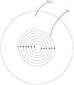
- Fig. 2is a schematic diagram of the winding of the voice coil wire on the diaphragm body in Fig. 1; wherein, the voice coil wire is wound in a spiral involute manner;
- FIG. 3is a schematic diagram of the force exerted on the voice coil wire in the magnetic circuit system in FIG. 1 .
- connectionand “fixation” should be understood in a broad sense, for example, “fixation” can be a fixed connection, a detachable connection, or an integral body; It can be a mechanical connection or an electrical connection; it can be a direct connection or an indirect connection through an intermediary, and it can be an internal communication between two elements or an interaction relationship between two elements, unless otherwise clearly defined.
- fixationcan be a fixed connection, a detachable connection, or an integral body; It can be a mechanical connection or an electrical connection; it can be a direct connection or an indirect connection through an intermediary, and it can be an internal communication between two elements or an interaction relationship between two elements, unless otherwise clearly defined.
- the present inventionproposes a loudspeaker, which aims to reduce the volume of the loudspeaker, so as to facilitate the loading and use of miniaturized electronic equipment.
- the speaker 100includes:
- the magnetic circuit system 10includes an inner magnetic circuit part 11 and an outer magnetic circuit part 13, and the outer magnetic circuit part 13 surrounds the inner magnetic circuit part 11 and is connected with the inner magnetic circuit part 11 enclosed to form a magnetic gap 10a;
- a vibration system 30, the vibration system 30includes a diaphragm 31 and a voice coil wire 33, the diaphragm 31 is covered above the magnetic circuit system 10, and the voice coil wire 33 is formed by the center of the diaphragm 31 Winding on the diaphragm 31 in a direction to the outer edge or in a direction from the outer edge of the diaphragm 31 to the center;
- the coil disk cover wound by the voice coil wire 33is arranged above the magnetic gap 10a, and the magnetic induction lines generated between the inner magnetic circuit part 11 and the outer magnetic circuit part 13 The direction is perpendicular to the winding direction of the voice coil wire 33 .
- the coil cover wound by the voice coil wire 33is arranged above the magnetic gap 10a, except that "when projected along the axial direction of the loudspeaker, the voice coil wire completely falls into the position of the magnetic gap" introduced later.
- the situation of “within the range”it can also be the situation of "the outer edge of the coil disk extends outward to the top of the outer magnetic circuit part 13", or the situation of "the inner edge of the coil disk extends inward to the inner magnetic circuit part 11". above” situation.
- the voice coil wire 33is wound on the voice coil tube, and the voice coil tube is inserted into the inner magnetic circuit part 11 and the outer magnetic circuit part. 13 together enclose the formed magnetic gap 10a.
- the voice coil wire 33When the voice coil wire 33 is energized and subjected to force, it will drive the voice coil tube to move, thereby pushing the diaphragm 31 to vibrate and radiate sound.
- a damperis also configured to ensure that the voice coil tube can move stably in the magnetic gap 10a without eccentricity.
- there are many components arranged in the axial direction of the loudspeaker 100which will cause the overall structural size of the loudspeaker 100 to be too large.
- the thinning of the loudspeaker 100is realized by reducing one or some components in the magnetic circuit system 10 .
- such a methodwill reduce the magnetic induction intensity of the magnetic circuit system 10 , thereby reducing the sensitivity (ie loudness) of the speaker 100 .
- the speaker 100 after thinninggenerally also has the problem of poor stability.
- the voice coil wire 33 originally wound on the voice coil tubeis changed to follow the direction from the center of the diaphragm 31 to the outer edge or from the outer edge of the diaphragm 31 to the center.
- the directionis wound on the diaphragm 31.
- the voice coil wire 33can be wound on the surface of the diaphragm 31 facing the magnetic circuit system 10 (the bottom view of the diaphragm 31 shown in FIG. 2 , the voice coil wire 33 is wound in a spiral involute manner. On the lower surface of the diaphragm 31.
- the voice coil wire 33can also be wound in other forms, such as a square involute), or it can be wound on the surface of the diaphragm 31 facing away from the magnetic circuit system 10, or The voice coil wire 33 can be wound on both the surface of the diaphragm 31 facing the magnetic circuit system 10 and the surface of the diaphragm 31 facing away from the magnetic circuit system 10 , or the voice coil wire 33 is wrapped in the diaphragm 31 .
- the winding method of the voice coil wire 33is innovatively changed from the conventional longitudinal winding to the horizontal winding, the vibration system 30 of the speaker 100 no longer needs to be equipped with a voice coil tube.
- the size of one voice coil tubeis reduced, the axial dimension of the vibration system 30 of the loudspeaker 100 is reduced, and the axial dimension of the loudspeaker 100 is reduced, so that "reducing the volume of the loudspeaker 100 is beneficial to miniaturized electronic equipment. carry and use" purposes.
- the vibration system 30 of the loudspeaker 100no longer needs to be equipped with a centering strut to ensure that the voice coil tube does not move eccentrically in the magnetic gap 10a.
- the axial dimension of the vibration system 30 of the loudspeaker 100can be further reduced, and the axial dimension of the speaker 100 can be further reduced.
- the axial height of the vibration system 30can be reduced, and the stability of the vibration system 30 during operation can also be increased (not easily eccentric).
- the voice coil wire 33is driven by cutting the magnetic induction line after being energized, it can directly push the diaphragm 31 to vibrate and radiate sound, and also improves the transient characteristics of the speaker 100 .
- connection mode between the voice coil wire 33 and the vibrating membrane 31can either be adhesively connected or covered (for example, the vibrating membrane 31 is composed of upper and lower unit film layers, The voice coil wire 33 is wrapped between the two unit film layers), or other effective and reasonable methods.
- the connection mode between the voice coil wire 33 and the vibrating membrane 31can either be adhesively connected or covered (for example, the vibrating membrane 31 is composed of upper and lower unit film layers, The voice coil wire 33 is wrapped between the two unit film layers), or other effective and reasonable methods.
- the diaphragm 31includes a diaphragm body 311 and a ring 313, and the ring 313 surrounds the diaphragm body 311, so The inner edge of the ring 313 is connected to the outer edge of the diaphragm body 311, and the outer edge of the ring 313 is connected to the frame 50 of the loudspeaker 100;
- the diaphragm body 311is a planar structure and is arranged opposite to the magnetic circuit system 10 , and the voice coil wire 33 is wound on the planar structure.
- the voice coil wire 33can be wound on the surface of the flat structure facing the magnetic circuit system 10 (according to the spiral involute method, the square involute method, or other effective and reasonable methods), or Wound on the surface of the flat structure facing away from the magnetic circuit system 10, the voice coil can also be wound on the surface of the flat structure facing the magnetic circuit system 10 and the surface of the flat structure facing away from the magnetic circuit system 10 The wire 33, or the voice coil wire 33 is wrapped in the flat structure.
- the shape of the diaphragm 31is improved from a conical or spherical shape to a flat plate shape, which not only facilitates the arrangement of the voice coil wire 33, but also reduces the axial dimension of the diaphragm 31, thereby The size of the overall structure of the loudspeaker 100 is reduced again in the axial direction.
- the better aspect of the flat-shaped diaphragm 31is reflected in the sound effect—the sound fidelity of the flat-shaped diaphragm 31 is higher, the reason is: taking the existing cone-shaped diaphragm 31 as an example, when it When the vibration produces sound, the sound is often concentrated in the "throat", compressed, and then transmitted.
- the sound that people hearis a compressed and deformed sound.
- the flat-shaped diaphragm 31does not compress the sound, thereby causing no deformation of the sound, and the middle and high frequencies are natural and real, and are not easy to be distorted.
- the voice coil wire 33is wound on the surface of the diaphragm 31 facing the magnetic circuit system 10 .
- the voice coil wire 33is wound on the surface of the flat structure facing the magnetic circuit system 10 .
- the voice coil wire 33will be closer to the magnetic circuit system 10 and the magnetic gap 10a.
- the distribution of the magnetic induction lines around the voice coil wire 33is denser, which is more conducive to the voice coil wire 33 to obtain a strong driving force and avoid the lack of driving force.
- such a configurationis also conducive to further reducing the axial size of the overall structure of the speaker 100 .
- the basin frame 50includes a supporting part 51 and a connecting part 53, and the supporting part 51 is arranged opposite to the flat structure for use To support the magnetic circuit system 10, the connecting portion 53 surrounds the supporting portion 51;
- the outer edge of the diaphragm 31is connected to the connecting portion 53 .
- the outer edge of the ring 313is connected to the upper end of the connecting portion 53 .
- the basin frame 50can not only provide stable support for the magnetic circuit system 10, ensure the stability of the magnetic field, and ensure the stability of the vibration system 30;
- the structureis simple, the manufacture is convenient, and it is beneficial to the assembly of the magnetic circuit system 10 and the assembly of the vibration system 30 , so that the production efficiency and reliability of the loudspeaker 100 can be improved.
- the outer magnetic circuit part 13includes a magnetically permeable yoke 131, and the magnetically permeable yoke 131 includes a cylinder part 1311 and a cover part 1313, so The two ends of the cylinder part 1311 are arranged through, and the cover part 1313 is sealed at the opening of one end of the cylinder part 1311;
- the inner magnetic circuit part 11includes a magnet 111 and a magnetically conductive plate 113, the magnet 111 and the magnetically permeable plate 113 are both arranged in the cylinder part 1311 and stacked on the cover part 1313 in sequence , the outer wall of the magnet 111 is spaced apart from the inner wall of the cylinder part 1311;
- the outer edge of the magnetic conductive plate 113is spaced apart from the cylinder portion 1311 to form the magnetic gap 10a.
- the cylinder part 1311is arranged vertically, and its upper and lower ends are arranged through.
- the cover portion 1313is horizontally disposed, and covers the lower opening of the cylinder portion 1311 to form a receiving space enclosed with the cylinder portion 1311 for accommodating the magnet 111 and the magnetic guide plate 113 .
- the magnet 111is disposed on the upper surface of the cover portion 1313 , and the outer sidewall is spaced apart from the inner sidewall of the cylinder portion 1311 .
- the magnetically conductive plate 113is disposed on the upper surface of the magnet 111 , and its outer edge is spaced apart from the cylindrical portion 1311 to form a magnetic gap 10a.
- the magnetic circuit system 10 of the loudspeaker 100has the advantages of simple structure, convenient manufacture, quick assembly, etc., and at the same time has strong structural stability, which can provide a stable magnetic field environment for the vibration system 30, thereby improving The reliability of the loudspeaker 100.
- the "external magnetic” magnetic circuit system 10 layoutcan also be adopted, and the “inner and outer magnetic” magnetic circuit system 10 layout method, or other effective and reasonable layout methods of the magnetic circuit system 10, those skilled in the art can make a reasonable choice according to the requirements of the actual application scenario, and will not repeat them here.
- soft magnetic materialscan be selected, such as iron, iron alloy, cobalt, cobalt alloy, nickel, nickel alloy and the like.
- hard magnetic materialscan be selected, for example: alnico permanent magnet alloy, iron chromium cobalt permanent magnet alloy, permanent magnet ferrite, rare earth permanent magnet material, composite permanent magnet material and the like.
- the distance between the surface of the magnetically conductive plate 113 facing away from the magnet 111 and the diaphragm 31is smaller than the orientation of the cylindrical portion 1311 The distance between one end surface of the diaphragm 31 and the diaphragm 31 .
- the upper end surface of the inner magnetic circuit part 11is flush with the upper end surface of the outer magnetic circuit part 13 to ensure that the magnetic induction lines pass through the magnetic gap 10a horizontally, and only the magnetic induction lines need to pass through the magnetic gap 10a from the outer magnetic circuit
- the upper end of the part 13points to the upper end of the inner magnetic circuit part 11 (or from the upper end of the inner magnetic circuit part 11 to the upper end of the outer magnetic circuit part 13)
- the technical solution of this embodimentadopts a thinner magnetically permeable plate 113 (that is, the distance between the surface of the magnetically permeable plate 113 away from the magnet 111 and the diaphragm 31 is configured to be smaller than that of the cylindrical portion 1311 towards the vibrating film 31 .
- the formation of the "tip"is conducive to the upward divergence of the magnetic induction line from the outgoing end of the magnetic induction line, so as to help the magnetic induction line pass through the voice coil line more accurately, more stably, and more vertically from above the magnetic gap 10a 33 (instead of most of the original magnetic induction lines running horizontally in the magnetic gap 10a), which is beneficial to the cooperation of the voice coil wire 33 and the magnetic circuit system 10, and is beneficial to the coil formed by the voice coil wire 33
- a stronger driving forceis obtained, so that the vibration performance of the vibration system 30 is better, and the acoustic performance of the speaker 100 is better.
- the axial dimension of the speaker 100can be reduced by about 2/5 without changing the overall performance of the speaker 100 .
- the magnetic guide plate 113can also be configured as follows:
- the outer wall of the magnet 111protrudes from the outer edge of the magnetic conductive plate 113 . That is, the outer edge of the magnetically conductive plate 113 is retracted within the range where the upper surface of the magnet 111 is located.
- the retracted design of the outer edge of the magnetically conductive plate 113can not only further help the inner magnetic circuit part and the outer magnetic circuit part to form an uneven magnetic induction line sending end and a magnetic induction line return end; It is beneficial to expand the range where the magnetic gap 10a is located.
- the synergistic effect of the two aspectscan further facilitate the upward divergence of the magnetic induction lines from the outgoing end of the magnetic induction lines, so as to help the magnetic induction lines to pass through the voice coil line vertically from above the magnetic gap 10a more accurately, more stably and more 33.
- the coil disk formed by the voice coil wire 33obtains a stronger driving force when energized, so that the vibration performance of the vibration system 30 is better, and the acoustic performance of the speaker 100 is better.
- the voice coil wire 33can also be configured as follows:
- the voice coil wire 33falls completely within the range of the magnetic gap 10 a.
- the winding of the voice coil wire 33is more concentrated, and is concentrated directly above the magnetic gap 10a.
- the magnetic induction lines generated between the inner and outer magnetic circuit partscan pass through the voice coil wires 33 more accurately and stably, and pass through more voice coil wires 33, so that the coils wound by the voice coil wires 33
- the coil disc made of the coilobtains a more powerful driving force when it is energized.
- the speaker 100also includes a reinforcing diaphragm, and the reinforcing diaphragm is attached to the diaphragm 31 and covers the diaphragm.
- the outer edge of the reinforcing membraneprotrudes into the area where the voice coil wire 33 is located.
- the voice coil wire 33is concentrated in the vertical range corresponding to the magnetic gap 10a, it can help the voice coil wire 33 to be placed in a magnetic field environment where the magnetic induction lines are more densely distributed, which is beneficial for the voice coil wire 33 to obtain powerful drive. However, it is also easy to cause mid-high frequency anti-phase vibration between the area where the voice coil wire 33 is located on the diaphragm 31 and the area of the diaphragm 31 surrounded by the voice coil wire 33, resulting in defects.
- the technical solution of this embodimentfurther strengthens the connection between the area where the voice coil wire 33 on the diaphragm 31 is located and the area of the diaphragm 31 surrounded by the voice coil wire 33 by using a reinforcing diaphragm.
- Make the connection between the area where the voice coil wire 33 on the diaphragm 31 and the area surrounded by the voice coil wire 33 of the diaphragm 31have higher strength and better integrity, so that the gap between the two can be better eliminated.
- the medium-high frequency anti-phase vibration phenomenonis used to improve the vibration performance of the vibration system 30 and optimize the acoustic performance of the loudspeaker 100 .
- the reinforcement diaphragmcan be made of the same material as that of the diaphragm 31 .
- the shape of the reinforcing membranecan match the shape of the area it covers, for example both are circular.
- the size of the reinforcing diaphragmcan be slightly larger than the size of the area it covers, so that the outer edge of the reinforcing diaphragm can extend into the area where the voice coil wire 33 is located.
- the area where the voice coil wire 33 is located on the diaphragm 31refers to the ring-shaped area from the innermost circle of voice coil wire 33 to the outermost circle of voice coil wire 33 .
- the area of the diaphragm 31 surrounded by the voice coil wire 33refers to the area within the innermost circle of the voice coil wire 33 .
- the peripheral area of the area where the voice coil wire 33 is locatedrefers to the area other than the outermost circle of the voice coil wire 33 .
- the reinforcement diaphragmcan be arranged in the above manner, and those skilled in the art can make a reasonable choice according to the requirements of the actual application scenario, and details will not be repeated here.
- connection between the area where the voice coil wire 33 is located on the diaphragm 31 and its peripheral areacan also be equipped with a reinforcing diaphragm to better eliminate the mid-high frequency reverse phase vibration between the two, thereby improving
- the vibration performance of the vibration system 30optimizes the acoustic performance of the speaker 100.
- the present inventionalso proposes an electronic device, which includes a loudspeaker 100.
- a loudspeaker 100For the specific structure of the loudspeaker 100, refer to the above-mentioned embodiments. Since this electronic device adopts all the technical solutions of all the above-mentioned embodiments, it has at least the advantages of all the above-mentioned embodiments. All the beneficial effects brought by all the technical solutions will not be repeated here.
- the electronic devicecan be, but is not limited to, a mobile phone, a notebook computer, a tablet computer, a personal digital assistant (Personal Digital Assistant, PDA), an e-book reader, an MP3 (Moving Picture Experts Compression Standard Audio Level 3, Moving Picture Experts Group Audio Layer III) player, MP4 (Moving Picture Experts Group Audio Layer IV) player, wearable device, navigator, handheld game console, virtual and reality equipment, augmented reality equipment, Speakers, headphones, etc.
- PDAPersonal Digital Assistant
- MP3Motion Picture Experts Compression Standard Audio Level 3, Moving Picture Experts Group Audio Layer III
- MP4Motion Picture Experts Group Audio Layer IV
Landscapes
- Physics & Mathematics (AREA)
- Engineering & Computer Science (AREA)
- Acoustics & Sound (AREA)
- Signal Processing (AREA)
- Audible-Bandwidth Dynamoelectric Transducers Other Than Pickups (AREA)
Abstract
Description
Translated fromChinese本申请要求于2021年09月22日提交中国专利局、申请号为202111107812.2、发明名称为“扬声器和电子设备”的中国专利申请的优先权,其全部内容通过引用结合在本申请中。This application claims the priority of the Chinese patent application with the application number 202111107812.2 and the title of the invention "Speaker and Electronic Equipment" filed with the China Patent Office on September 22, 2021, the entire contents of which are incorporated in this application by reference.
本发明涉及声学技术领域,特别涉及一种扬声器和应用该扬声器的电子设备。The invention relates to the technical field of acoustics, in particular to a loudspeaker and electronic equipment using the loudspeaker.
电动式扬声器作为应用最为广泛的扬声器,在音箱、耳机等电子设备中的应用率接近99%。电动式扬声器虽然具有成本低、性能稳定等优点,但还是存在尺寸较大的问题,不利于小型化的电子设备进行搭载和使用。As the most widely used loudspeaker, the electrodynamic loudspeaker has an application rate of nearly 99% in electronic equipment such as speakers and earphones. Although the dynamic speaker has the advantages of low cost and stable performance, it still has the problem of large size, which is not conducive to the installation and use of miniaturized electronic equipment.
发明内容Contents of the invention
本发明的主要目的是提出一种扬声器和应用该扬声器的电子设备,旨在减小扬声器体积,以有利于小型化的电子设备进行搭载和使用。The main purpose of the present invention is to provide a loudspeaker and electronic equipment using the loudspeaker, aiming at reducing the volume of the loudspeaker, so as to facilitate the loading and use of miniaturized electronic equipment.
为实现上述目的,本发明提出一种扬声器,该扬声器包括:In order to achieve the above object, the present invention proposes a loudspeaker, which includes:
磁路系统,所述磁路系统包括内磁路部分和外磁路部分,所述外磁路部分环绕在所述内磁路部分四周,并与所述内磁路部分围合形成磁间隙;和A magnetic circuit system, the magnetic circuit system includes an inner magnetic circuit part and an outer magnetic circuit part, the outer magnetic circuit part surrounds the inner magnetic circuit part and forms a magnetic gap surrounded by the inner magnetic circuit part; and
振动系统,所述振动系统包括振膜和音圈线,所述振膜罩设在所述磁路系统的上方,所述音圈线按照由所述振膜的中心至外缘的方向或者按照由所述振膜的外缘至中心的方向绕制在所述振膜上;A vibration system, the vibration system includes a diaphragm and a voice coil wire, the diaphragm cover is arranged above the magnetic circuit system, and the voice coil wire follows the direction from the center of the diaphragm to the outer edge or according to the direction from the center of the diaphragm to the outer edge The direction from the outer edge of the diaphragm to the center is wound on the diaphragm;
其中,由所述音圈线绕制而成的线圈盘罩设在所述磁间隙的上方,所述内磁路部分和所述外磁路部分之间产生的磁感线的方向,与所述音圈线的绕制方向垂直设置。Wherein, the coil disk cover made of the voice coil wire is arranged above the magnetic gap, and the direction of the magnetic induction line generated between the inner magnetic circuit part and the outer magnetic circuit part is consistent with the direction of the magnetic induction line. The winding direction of the voice coil wire is set vertically.
在本发明一实施例中,所述振膜包括振膜本体和折环,所述折环环绕在 所述振膜本体四周,所述折环的内缘连接于所述振膜本体的外缘,所述折环的外缘连接于所述扬声器的盆架;In an embodiment of the present invention, the diaphragm includes a diaphragm body and a ring, the ring surrounds the diaphragm body, and the inner edge of the ring is connected to the outer edge of the diaphragm body , the outer edge of the ring is connected to the frame of the loudspeaker;
所述振膜本体为平板状结构,并与所述磁路系统相对设置,所述音圈线绕制在所述平板状结构上。The diaphragm body is a planar structure, and is arranged opposite to the magnetic circuit system, and the voice coil wire is wound on the planar structure.
在本发明一实施例中,所述音圈线绕制在所述振膜的面向所述磁路系统的表面上。In an embodiment of the present invention, the voice coil wire is wound on the surface of the diaphragm facing the magnetic circuit system.
在本发明一实施例中,所述盆架包括承托部和连接部,所述承托部与所述平板状结构相对设置,用于承托所述磁路系统,所述连接部环绕在所述承托部四周;In an embodiment of the present invention, the pot frame includes a supporting portion and a connecting portion, the supporting portion is arranged opposite to the flat structure for supporting the magnetic circuit system, and the connecting portion surrounds the around the supporting part;
所述振膜的外缘连接于所述连接部。The outer edge of the diaphragm is connected to the connecting portion.
在本发明一实施例中,所述外磁路部分包括导磁轭,所述导磁轭包括筒体部和封盖部,所述筒体部两端贯通设置,所述封盖部封盖在所述筒体部的一端开口处;In an embodiment of the present invention, the outer magnetic circuit part includes a magnetically permeable yoke, and the magnetically permeable yoke includes a cylinder part and a cover part, the two ends of the cylinder part are connected through, and the cover part covers at one end opening of the cylinder portion;
所述内磁路部分包括磁体和导磁板,所述磁体和所述导磁板均设置在所述筒体部内,且依次叠放在所述封盖部上,所述磁体的外侧壁与所述筒体部的内侧壁间隔设置;The inner magnetic circuit part includes a magnet and a magnetically conductive plate, and the magnet and the magnetically conductive plate are both arranged in the cylinder part and stacked on the cover part in sequence. The outer wall of the magnet and the magnetically conductive plate The inner side walls of the cylinder part are arranged at intervals;
所述导磁板的外缘与所述筒体部间隔设置,以形成所述磁间隙。The outer edge of the magnetic conductive plate is spaced apart from the cylindrical part to form the magnetic gap.
在本发明一实施例中,所述导磁板的背离所述磁体的表面距所述振膜的距离小于所述筒体部的朝向所述振膜的一端端面距所述振膜的距离。In an embodiment of the present invention, the distance between the surface of the magnetic conductive plate facing away from the magnet and the diaphragm is smaller than the distance between the end surface of the cylindrical part facing the diaphragm and the diaphragm.
在本发明一实施例中,所述磁体的外侧壁凸出所述导磁板的外缘设置。In an embodiment of the present invention, the outer side wall of the magnet protrudes from the outer edge of the magnetic conductive plate.
在本发明一实施例中,在沿所述扬声器的轴向进行投影时,所述音圈线完全落入所述磁间隙所在范围内。In an embodiment of the present invention, when projected along the axial direction of the loudspeaker, the voice coil wire completely falls within the range where the magnetic gap is located.
在本发明一实施例中,所述扬声器还包括补强膜片,所述补强膜片贴设 于所述振膜,并覆盖所述振膜的被所述音圈线所包绕的区域,所述补强膜片的外缘伸入所述音圈线所在区域内。In an embodiment of the present invention, the loudspeaker further includes a reinforcing diaphragm, the reinforcing diaphragm is attached to the diaphragm and covers the area of the diaphragm surrounded by the voice coil wire , the outer edge of the reinforcing diaphragm extends into the area where the voice coil wire is located.
为实现上述目的,本发明还提供一种电子设备,该电子设备包括扬声器,该扬声器包括:In order to achieve the above object, the present invention also provides an electronic device, the electronic device includes a loudspeaker, and the loudspeaker includes:
磁路系统,所述磁路系统包括内磁路部分和外磁路部分,所述外磁路部分环绕在所述内磁路部分四周,并与所述内磁路部分围合形成磁间隙;和A magnetic circuit system, the magnetic circuit system includes an inner magnetic circuit part and an outer magnetic circuit part, the outer magnetic circuit part surrounds the inner magnetic circuit part and forms a magnetic gap surrounded by the inner magnetic circuit part; and
振动系统,所述振动系统包括振膜和音圈线,所述振膜罩设在所述磁路系统的上方,所述音圈线按照由所述振膜的中心至外缘的方向或者按照由所述振膜的外缘至中心的方向绕制在所述振膜上;A vibration system, the vibration system includes a diaphragm and a voice coil wire, the diaphragm cover is arranged above the magnetic circuit system, and the voice coil wire follows the direction from the center of the diaphragm to the outer edge or according to the direction from the center of the diaphragm to the outer edge The direction from the outer edge of the diaphragm to the center is wound on the diaphragm;
其中,由所述音圈线绕制而成的线圈盘罩设在所述磁间隙的上方,所述内磁路部分和所述外磁路部分之间产生的磁感线的方向,与所述音圈线的绕制方向垂直设置。Wherein, the coil disk cover made of the voice coil wire is arranged above the magnetic gap, and the direction of the magnetic induction line generated between the inner magnetic circuit part and the outer magnetic circuit part is consistent with the direction of the magnetic induction line. The winding direction of the voice coil wire is set vertically.
本发明的技术方案,将原本缠绕在音圈管上的音圈线改为按照由振膜的中心至外缘的方向或者按照由振膜的外缘至中心的方向绕制在振膜上。此时,由于将音圈线的缠绕方式由常规的纵向缠绕创新地改为了横向缠绕,扬声器的振动系统不再需要配置音圈管,从整体上看即在扬声器的轴向上减少了一个音圈管的尺寸,扬声器的振动系统的轴向尺寸得以降低,扬声器的轴向尺寸得以降低,从而可以实现“减小扬声器体积,以有利于小型化的电子设备进行搭载和使用”的目的。与此同时,由于音圈管的取消,扬声器的振动系统也不再需要配置定心支片来保证音圈管在磁间隙内不偏心运动,扬声器的振动系统的轴向尺寸得以进一步降低,扬声器的轴向尺寸得以进一步降低。当然,可以理解地,由于上述创新的设计,完全不涉及对磁路系统的减配,磁路系统的磁感应强度并不会受到影响,因磁感应强度降低而导致的一系列问题也不会发生。In the technical solution of the present invention, the voice coil wire originally wound on the voice coil tube is wound on the diaphragm in the direction from the center to the outer edge of the diaphragm or in the direction from the outer edge to the center of the diaphragm. At this time, since the winding method of the voice coil wire is innovatively changed from the conventional longitudinal winding to the horizontal winding, the vibration system of the loudspeaker no longer needs to be equipped with a voice coil tube, which reduces the axial direction of the loudspeaker by one tone. The size of the coil tube, the axial dimension of the vibration system of the loudspeaker can be reduced, and the axial dimension of the loudspeaker can be reduced, so that the purpose of "reducing the volume of the loudspeaker to facilitate the loading and use of miniaturized electronic equipment" can be achieved. At the same time, due to the cancellation of the voice coil tube, the vibration system of the speaker no longer needs to be equipped with a centering piece to ensure that the voice coil tube does not move eccentrically in the magnetic gap, and the axial dimension of the vibration system of the speaker can be further reduced. The axial dimension can be further reduced. Of course, it is understandable that due to the above-mentioned innovative design, no reduction of the magnetic circuit system is involved at all, the magnetic induction of the magnetic circuit system will not be affected, and a series of problems caused by the reduction of the magnetic induction will not occur.
另一方面,由于音圈管和定心支片等部件被取消,振动系统的重心得以降低,振动系统运行时的稳定性还得以增加(不易偏心)。并且,由于音圈线通电后切割磁感线而被驱动,可以直接推动振膜振动而辐射声音,还提高了扬声器的瞬态特性。On the other hand, since parts such as the voice coil tube and the centering strut are canceled, the center of gravity of the vibration system can be lowered, and the stability of the vibration system can be increased (not easy to be eccentric). Moreover, since the voice coil wire is driven by cutting the magnetic induction line after being energized, it can directly push the diaphragm to vibrate and radiate sound, and also improves the transient characteristics of the speaker.
为了更清楚地说明本发明实施例或现有技术中的技术方案,下面将对实施例或现有技术描述中所需要使用的附图作简单地介绍,显而易见地,下面描述中的附图仅仅是本发明的一些实施例,对于本领域普通技术人员来讲,在不付出创造性劳动的前提下,还可以根据这些附图示出的结构获得其他的附图。In order to more clearly illustrate the technical solutions in the embodiments of the present invention or the prior art, the following will briefly introduce the drawings that need to be used in the description of the embodiments or the prior art. Obviously, the accompanying drawings in the following description are only These are some embodiments of the present invention. For those skilled in the art, other drawings can also be obtained according to the structures shown in these drawings without creative effort.
图1为本发明扬声器一实施例的结构示意图;Fig. 1 is a schematic structural view of an embodiment of the loudspeaker of the present invention;
图2为图1中音圈线在振膜本体上绕制的示意图;其中,音圈线采用螺旋渐开的方式绕制;Fig. 2 is a schematic diagram of the winding of the voice coil wire on the diaphragm body in Fig. 1; wherein, the voice coil wire is wound in a spiral involute manner;
图3为图1中音圈线在磁路系统中受力的示意图。FIG. 3 is a schematic diagram of the force exerted on the voice coil wire in the magnetic circuit system in FIG. 1 .
附图标号说明:Explanation of reference numbers:
本发明目的的实现、功能特点及优点将结合实施例,参照附图做进一步说明。The realization of the purpose of the present invention, functional characteristics and advantages will be further described in conjunction with the embodiments and with reference to the accompanying drawings.
下面将结合本发明实施例中的附图,对本发明实施例中的技术方案进行清楚、完整地描述,显然,所描述的实施例仅仅是本发明的一部分实施例, 而不是全部的实施例。基于本发明中的实施例,本领域普通技术人员在没有作出创造性劳动前提下所获得的所有其他实施例,都属于本发明保护的范围。The following will clearly and completely describe the technical solutions in the embodiments of the present invention with reference to the accompanying drawings in the embodiments of the present invention. Obviously, the described embodiments are only part of the embodiments of the present invention, rather than all the embodiments. Based on the embodiments of the present invention, all other embodiments obtained by persons of ordinary skill in the art without creative efforts fall within the protection scope of the present invention.
需要说明,本发明实施例中所有方向性指示(诸如上、下、左、右、前、后……)仅用于解释在某一特定姿态(如附图所示)下各部件之间的相对位置关系、运动情况等,如果该特定姿态发生改变时,则该方向性指示也相应地随之改变。It should be noted that all directional indications (such as up, down, left, right, front, back...) in the embodiments of the present invention are only used to explain the relationship between the components in a certain posture (as shown in the accompanying drawings). Relative positional relationship, movement conditions, etc., if the specific posture changes, the directional indication will also change accordingly.
另外,在本发明中如涉及“第一”、“第二”等的描述仅用于描述目的,而不能理解为指示或暗示其相对重要性或者隐含指明所指示的技术特征的数量。由此,限定有“第一”、“第二”的特征可以明示或者隐含地包括至少一个该特征。在本发明的描述中,“若干”、“多个”的含义是至少两个,例如两个,三个等,除非另有明确具体的限定。In addition, in the present invention, descriptions such as "first", "second" and so on are used for description purposes only, and should not be understood as indicating or implying their relative importance or implicitly indicating the quantity of indicated technical features. Thus, the features defined as "first" and "second" may explicitly or implicitly include at least one of these features. In the description of the present invention, "several" and "plurality" mean at least two, such as two, three, etc., unless otherwise specifically defined.
在本发明中,除非另有明确的规定和限定,术语“连接”、“固定”等应做广义理解,例如,“固定”可以是固定连接,也可以是可拆卸连接,或成一体;可以是机械连接,也可以是电连接;可以是直接相连,也可以通过中间媒介间接相连,可以是两个元件内部的连通或两个元件的相互作用关系,除非另有明确的限定。对于本领域的普通技术人员而言,可以根据具体情况理解上述术语在本发明中的具体含义。In the present invention, unless otherwise specified and limited, the terms "connection" and "fixation" should be understood in a broad sense, for example, "fixation" can be a fixed connection, a detachable connection, or an integral body; It can be a mechanical connection or an electrical connection; it can be a direct connection or an indirect connection through an intermediary, and it can be an internal communication between two elements or an interaction relationship between two elements, unless otherwise clearly defined. Those of ordinary skill in the art can understand the specific meanings of the above terms in the present invention according to specific situations.
另外,本发明各个实施例之间的技术方案可以相互结合,但是必须是以本领域普通技术人员能够实现为基础,当技术方案的结合出现相互矛盾或无法实现时应当认为这种技术方案的结合不存在,也不在本发明要求的保护范围之内。In addition, the technical solutions of the various embodiments of the present invention can be combined with each other, but it must be based on the realization of those skilled in the art. When the combination of technical solutions is contradictory or cannot be realized, it should be considered as a combination of technical solutions. Does not exist, nor is it within the scope of protection required by the present invention.
针对背景技术所反映的技术问题,本发明提出一种扬声器,旨在减小扬声器体积,以有利于小型化的电子设备进行搭载和使用。Aiming at the technical problems reflected in the background technology, the present invention proposes a loudspeaker, which aims to reduce the volume of the loudspeaker, so as to facilitate the loading and use of miniaturized electronic equipment.
下面将在具体实施例中对本发明提出的扬声器的具体结构进行说明:The specific structure of the loudspeaker proposed by the present invention will be described below in specific embodiments:
如图1至图3所示,在本发明扬声器100一实施例中,该扬声器100包括:As shown in Figures 1 to 3, in an embodiment of the
磁路系统10,所述磁路系统10包括内磁路部分11和外磁路部分13,所述外磁路部分13环绕在所述内磁路部分11四周,并与所述内磁路部分11围合形成磁间隙10a;和The
振动系统30,所述振动系统30包括振膜31和音圈线33,所述振膜31罩设 在所述磁路系统10的上方,所述音圈线33按照由所述振膜31的中心至外缘的方向或者按照由所述振膜31的外缘至中心的方向绕制在所述振膜31上;A
其中,由所述音圈线33绕制而成的线圈盘罩设在所述磁间隙10a的上方,所述内磁路部分11和所述外磁路部分13之间产生的磁感线的方向,与所述音圈线33的绕制方向垂直设置。Wherein, the coil disk cover wound by the
可以理解地,由音圈线33绕制而成的线圈盘罩设在磁间隙10a的上方,除了后文中介绍的“在沿扬声器的轴向进行投影时,音圈线完全落入磁间隙所在范围内”的情形外,还可以是“线圈盘的外缘向外延伸至外磁路部分13的上方”的情形,亦或是“线圈盘的内缘向内延伸至内磁路部分11的上方”的情形。It can be understood that the coil cover wound by the
需要说明的是,对于现有绝大部分的扬声器100而言,其音圈线33是缠绕在音圈管上的,音圈管则是插装在由内磁路部分11和外磁路部分13共同围合形成的磁间隙10a中的。当音圈线33通电受力时,会带动音圈管运动,从而推动振膜31振动而辐射声音。另一方面,还会配置定心支片来保证音圈管能够在磁间隙10a中稳定运动而不发生偏心。但是,这样的设计,在扬声器100轴向上布局的部件较多,会导致扬声器100整体结构尺寸过大。It should be noted that, for most existing
通常情况下,扬声器100一般是通过减少磁路系统10中的某个或某些部件而实现减薄的。但是,这样的方式,会导致磁路系统10的磁感应强度降低,从而致使扬声器100的灵敏度(即响度)下降。并且,减薄后的扬声器100一般还会出现稳定性变差的问题,原因有两个方面:(1)没有足够的磁感应强度推动振膜31,即驱动力不足导致振膜31易偏心振动,从而容易出现音圈“擦圈”(即碰到内磁路部分11和外磁路部分13)的不良;(2)由于振膜31还是呈现常规的锥形或球顶形,在驱动力不足的情况下更加容易产生振膜31与折环313的连接位置或者振膜31的某个部分在中高频逆相位振动,即产生扭曲变形。Usually, the thinning of the
为了规避上述问题,本实施例的技术方案,将原本缠绕在音圈管上的音圈线33改为按照由振膜31的中心至外缘的方向或者按照由振膜31的外缘至中心的方向绕制在振膜31上。具体地,音圈线33既可以绕制在振膜31的面向磁路系统10的表面上(如图2所示的振膜31的仰视图,音圈线33按照螺旋渐开的方式绕制在振膜31的下表面上。当然,音圈线33也可以采用其他形式进行绕 制,例如方形渐开),也可以绕制在振膜31的背向磁路系统10的表面上,还可以在振膜31的面向磁路系统10的表面和振膜31的背向磁路系统10的表面都绕制有音圈线33,亦或是音圈线33包覆在振膜31中。此时,由于将音圈线33的缠绕方式由常规的纵向缠绕创新地改为了横向缠绕,扬声器100的振动系统30不再需要配置音圈管,从整体上看即在扬声器100的轴向上减少了一个音圈管的尺寸,扬声器100的振动系统30的轴向尺寸得以降低,扬声器100的轴向尺寸得以降低,从而可以实现“减小扬声器100体积,以有利于小型化的电子设备进行搭载和使用”的目的。与此同时,由于音圈管的取消,扬声器100的振动系统30也不再需要配置定心支片来保证音圈管在磁间隙10a内不偏心运动,扬声器100的振动系统30的轴向尺寸得以进一步降低,扬声器100的轴向尺寸得以进一步降低。当然,可以理解地,由于上述创新的设计,完全不涉及对磁路系统10的减配,磁路系统10的磁感应强度并不会受到影响,因磁感应强度降低而导致的一系列问题也不会发生。In order to avoid the above problems, in the technical solution of this embodiment, the
另一方面,由于音圈管和定心支片等部件被取消,振动系统30的轴向高度得以降低,振动系统30运行时的稳定性还得以增加(不易偏心)。并且,由于音圈线33通电后切割磁感线而被驱动,可以直接推动振膜31振动而辐射声音,还提高了扬声器100的瞬态特性。On the other hand, since parts such as the voice coil tube and the centering strut are eliminated, the axial height of the
需要补充的是,音圈线33与振膜31的连接方式,既可以采用胶粘连接的方式,也可以采用包覆的方式(例如,振膜31由上、下两张单元膜层构成,音圈线33包覆在这两张单元膜层之间),亦或是其他有效且合理的方式。本领域技术人员可以根据实际应用场景的需求,进行合理选择,在此不再一一赘述。It should be added that the connection mode between the
如图1至图3所示,在本发明扬声器100一实施例中,所述振膜31包括振膜本体311和折环313,所述折环313环绕在所述振膜本体311四周,所述折环313的内缘连接于所述振膜本体311的外缘,所述折环313的外缘连接于所述扬声器100的盆架50;As shown in Figures 1 to 3, in an embodiment of the
所述振膜本体311为平板状结构,并与所述磁路系统10相对设置,所述音圈线33绕制在所述平板状结构上。The
可以理解地,音圈线33既可以绕制在平板状结构的面向磁路系统10的表 面上(按照螺旋渐开的方式,方形渐开的方式,或者其他有效且合理的方式),也可以绕制在平板状结构的背向磁路系统10的表面上,还可以在平板状结构的面向磁路系统10的表面和平板状结构的背向磁路系统10的表面都绕制有音圈线33,亦或是音圈线33包覆在平板状结构中。It can be understood that the
本实施例的技术方案,将振膜31的形状从锥形或球顶形改良为平板形,不仅方便音圈线33的布置,而且还可使振膜31的轴向尺寸得以减小,从而在轴向上再次减小扬声器100整体结构的尺寸。另一方面,平板形的振膜31更优的方面体现在音效——平板形的振膜31的声音保真度更高,原因是:以现有锥形的振膜31为例,当它振动发出声音时,往往将声音集中在“喉部”,经过压缩,再传播出来。因此,人们听到的声音,是经过压缩而变形的声音。然而,平板形的振膜31不会对声音进行压缩,从而不会引起声音的变形,中高频自然且真实,不易失真。In the technical solution of this embodiment, the shape of the
如图1至图3所示,在本发明扬声器100一实施例中,所述音圈线33绕制在所述振膜31的面向所述磁路系统10的表面上。具体地,音圈线33绕制在平板状结构的面向磁路系统10的表面上。As shown in FIGS. 1 to 3 , in an embodiment of the
可以理解地,在本实施例的设计下,音圈线33将会更加接近磁路系统10、接近磁间隙10a。此时,音圈线33周围的磁感线的分布更加密集,更加有利于音圈线33获得强大的驱动力,避免驱动力的缺失。同时,这样的配置方式,还有利于进一步降低扬声器100整体结构的轴向尺寸。It can be understood that under the design of this embodiment, the
如图1至图3所示,在本发明扬声器100一实施例中,所述盆架50包括承托部51和连接部53,所述承托部51与所述平板状结构相对设置,用于承托所述磁路系统10,所述连接部53环绕在所述承托部51四周;As shown in Figures 1 to 3, in an embodiment of the
所述振膜31的外缘连接于所述连接部53。具体地,折环313的外缘连接于连接部53的上端。The outer edge of the
可以理解地,在本实施例的设计下,盆架50不仅可以为磁路系统10提供稳定的支撑作用,保证磁场的稳定,保证振动系统30运行的稳定;而且喇叭状的设置方式,还具有结构简单、制造方便、有利于磁路系统10的组装、有利于振动系统30的组装等优势,从而可以提升扬声器100的生产效率和可靠 性。It can be understood that under the design of this embodiment, the
如图1至图3所示,在本发明扬声器100一实施例中,所述外磁路部分13包括导磁轭131,所述导磁轭131包括筒体部1311和封盖部1313,所述筒体部1311两端贯通设置,所述封盖部1313封盖在所述筒体部1311的一端开口处;As shown in FIG. 1 to FIG. 3 , in an embodiment of the
所述内磁路部分11包括磁体111和导磁板113,所述磁体111和所述导磁板113均设置在所述筒体部1311内,且依次叠放在所述封盖部1313上,所述磁体111的外侧壁与所述筒体部1311的内侧壁间隔设置;The inner
所述导磁板113的外缘与所述筒体部1311间隔设置,以形成所述磁间隙10a。The outer edge of the magnetic
本实施例中,筒体部1311竖直设置,其上下两端贯通设置。封盖部1313呈水平设置状态,且封盖在筒体部1311的下端开口处,以与筒体部1311围合形成收容空间,用于收容磁体111和导磁板113。进一步地,磁体111设置在封盖部1313的上表面上,且外侧壁与筒体部1311的内侧壁间隔设置。导磁板113设置在磁体111的上表面上,且外缘与筒体部1311间隔设置,以形成磁间隙10a。此时,以图3所示的磁场布局形式为例,则:In this embodiment, the
由筒体部1311上端发出的若干磁感线中,存在部分磁感线会以类似“抛物线”的形式向上、向音圈线33所在位置延伸,并在垂直穿过音圈线33之后向下、向导磁板113的外缘所在位置延伸,最后由导磁板113的外缘回到内磁路部分11,实现循环。这样,当振膜31上的音圈线33通电时,音圈线33便会在磁场的作用下直接带动振膜31在竖直方向上发生振动而向外辐射声波能量,完成发声。Among the several lines of magnetic induction emanating from the upper end of the
可以理解地,在本实施例的设计下,扬声器100的磁路系统10具有结构简单、制造方便、装配快捷等优势,同时结构稳定性强,能够为振动系统30提供稳定的磁场环境,从而提升扬声器100的可靠性。Understandably, under the design of this embodiment, the
当然,除了采用上述“内磁式”磁路系统10布局方式之外,在其他实施例中,还可以采用“外磁式”磁路系统10布局方式,“内外磁式”磁路系统10布局方式,或者其他有效且合理的磁路系统10布局方式,本领域技术人员可以根据实际应用场景的需求,进行合理选择,在此不再一一赘述。Of course, in addition to adopting the above-mentioned "inner magnetic"
需要说明的是,关于导磁轭131、导磁板113的材质,可以选择软磁材料, 例如:铁、铁合金、钴、钴合金、镍、镍合金等。关于磁体111的材质,可以选择硬磁材料,例如:铝镍钴系永磁合金、铁铬钴系永磁合金、永磁铁氧体、稀土永磁材料、复合永磁材料等。It should be noted that, regarding the materials of the
如图1至图3所示,在本发明扬声器100一实施例中,所述导磁板113的背离所述磁体111的表面距所述振膜31的距离小于所述筒体部1311的朝向所述振膜31的一端端面距所述振膜31的距离。As shown in FIGS. 1 to 3 , in an embodiment of the
需要说明的是,由于音圈线33缠绕方式的改变,需要对音圈线33所处的新位置进行束磁定心,而不需要像原先一样将磁感线束缚在磁间隙10a中。因此,不需要厚度更大的导磁板113(即将导磁板113的背离磁体111的表面距振膜31的距离和筒体部1311的朝向振膜31的一端端面距振膜31的距离配置成一致的情形,也即内磁路部分11的上端面与外磁路部分13的上端面齐平)来保证磁感线水平穿过磁间隙10a,而仅需要磁感线在从外磁路部分13的上端指向内磁路部分11的上端(或者从内磁路部分11的上端指向外磁路部分13的上端)的过程中,从磁间隙10a上方穿过时垂直于音圈线33即可。因此,本实施例的技术方案,采用了厚度更薄的导磁板113(即将导磁板113的背离磁体111的表面距振膜31的距离配置成小于筒体部1311的朝向振膜31的一端端面距振膜31的距离的情形),以帮助内磁路部分和外磁路部分之间形成不齐平的磁感线发出端和磁感线回流端,即有利于两个不对等的“尖端”的形成,从而有利于磁感线由磁感线发出端向上发散地发出,以帮助磁感线更准确地、更稳定地、更多地从磁间隙10a上方垂直穿过音圈线33(而非原来一样的绝大部分磁感线水平在磁间隙10a中穿行),进而有利于音圈线33与磁路系统10的配合,有利于由音圈线33绕制而成的线圈盘通电时获得更加强大的驱动力,以使得振动系统30的振动性能更佳,扬声器100的声学性能更佳。It should be noted that due to the change of the winding method of the
此外,还需要说明的是,基于本实施例的设计以及前述音圈线33横向缠绕的设计,在扬声器100整体性能不改变的情况下,能大约降低扬声器100的轴向尺寸2/5。In addition, it should be noted that based on the design of this embodiment and the design of the
进一步地,为了帮助磁感线更准确地、更稳定地、更多地从磁间隙10a上方垂直穿过音圈线33,以有利于音圈线33与磁路系统10的配合,有利于由音 圈线33绕制而成的线圈盘通电时获得更加强大的驱动力,从而使得振动系统30的振动性能更佳,扬声器100的声学性能更佳,还可以对导磁板113做如下配置:Further, in order to help the magnetic induction line to pass through the
如图1至图3所示,在本发明扬声器100一实施例中,所述磁体111的外侧壁凸出所述导磁板113的外缘设置。即,导磁板113的外缘内缩在磁体111的上表面所在范围内。As shown in FIG. 1 to FIG. 3 , in an embodiment of the
可以理解地,导磁板113的外缘内缩的设计,不仅能够进一步帮助内磁路部分和外磁路部分在其间形成不平齐的磁感线发出端和磁感线回流端;而且还有利于扩大磁间隙10a所在范围。两方面协同作用,可进一步有利于磁感线由磁感线发出端向上发散地发出,以帮助磁感线更准确地、更稳定地、更多地从磁间隙10a上方垂直穿过音圈线33。It can be understood that the retracted design of the outer edge of the magnetically
进一步地,为了帮助磁感线更准确地、更稳定地、更多地从磁间隙10a上方垂直穿过音圈线33,以有利于音圈线33与磁路系统10的配合,有利于由音圈线33绕制而成的线圈盘通电时获得更加强大的驱动力,从而使得振动系统30的振动性能更佳,扬声器100的声学性能更佳,还可以对音圈线33做如下配置:Further, in order to help the magnetic induction line to pass through the
如图1至图3所示,在本发明扬声器100一实施例中,在沿所述扬声器100的轴向进行投影时,所述音圈线33完全落入所述磁间隙10a所在范围内。As shown in FIG. 1 to FIG. 3 , in an embodiment of the
可以理解地,在本实施例的设计下,音圈线33的缠绕更加集中,且集中在磁间隙10a的正上方。这样,内、外磁路部分之间产生的磁感线便可以更准确地、更稳定地穿过音圈线33,且穿过更多的音圈线33,从而使由音圈线33绕制而成的线圈盘通电时获得更加强大的驱动力。It can be understood that under the design of this embodiment, the winding of the
如图1至图3所示,在本发明扬声器100一实施例中,所述扬声器100还包括补强膜片,所述补强膜片贴设于所述振膜31,并覆盖所述振膜31的被所述音圈线33所包绕的区域,所述补强膜片的外缘伸入所述音圈线33所在区域内。As shown in Figures 1 to 3, in an embodiment of the
需要说明的是,虽然音圈线33集中在磁间隙10a对应的竖直范围内的设计,可以帮助音圈线33置身于磁感线分布更加密集的磁场环境中,有利于音圈线33获得强大的驱动力。但是,也容易导致振膜31上音圈线33所在区域与 振膜31的被音圈线33所包绕的区域之间发生中高频逆相位振动,从而导致不良。It should be noted that although the
为了解决该问题,本实施例的技术方案,利用补强膜片对振膜31上音圈线33所在区域和振膜31的被音圈线33所包绕的区域做了进一步的加强连接,使振膜31上音圈线33所在区域和振膜31的被音圈线33所包绕的区域的连接处的强度更高、整体性更好,从而可较好地消除二者之间的中高频逆相位振动现象,以提升振动系统30的振动性能,优化扬声器100的声学性能。In order to solve this problem, the technical solution of this embodiment further strengthens the connection between the area where the
需要说明的是,补强膜片可以采用与振膜31相同的材质。补强膜片的形状可以与其覆盖的区域形状相匹配,例如二者都呈圆形。补强膜片的大小可以比其覆盖的区域的大小略大一些,以使补强膜片的外缘可以伸入音圈线33所在区域内。进一步地,振膜31上音圈线33所在区域,是指从最内侧一圈音圈线33至最外侧一圈音圈线33的环形区域。振膜31的被音圈线33所包绕的区域,是指最内侧一圈音圈线33以内的区域。音圈线33所在区域的外围区域,是指最外侧一圈音圈线33以外的区域。It should be noted that the reinforcement diaphragm can be made of the same material as that of the
此外,对加强膜片与音圈线33的位置关系,做如下说明(以音圈线33绕制在振膜31的面向磁路系统10的表面为例):In addition, the positional relationship between the reinforcing diaphragm and the
情形一(补强膜片和音圈线33位于振膜31的同一侧):补强膜片贴设在(可以通过例如胶粘连接等方式)振膜31的面向磁路系统10的表面,补强膜片的中间部分覆盖在振膜31的被音圈线33所包绕的区域的下表面,补强膜片的外缘覆盖在内侧一圈或多圈音圈线33上。Situation 1 (the reinforcement diaphragm and the
情形二(补强膜片和音圈线33位于振膜31的不同侧):补强膜片贴设在(可以通过例如胶粘连接等方式)振膜31的背向磁路系统10的表面,补强膜片的中间部分覆盖在振膜31的被音圈线33所包绕的区域的上表面,补强膜片的外缘覆盖在振膜31上表面的与内侧一圈或多圈音圈线33对应的部分上。Situation 2 (the reinforcement diaphragm and the
当音圈线33处理其他绕制情形时,可以参照上述方式对补强膜片进行布置,本领域技术人员可以根据实际应用场景的需求,进行合理选择,在此不再一一赘述。When the
当然,可以理解地,振膜31上音圈线33所在区域与其外围区域的连接处也可以配置有补强膜片,以较好地消除二者之间的中高频逆相位振动现象,从而提升振动系统30的振动性能,优化扬声器100的声学性能。Of course, it can be understood that the connection between the area where the
本发明还提出一种电子设备,该电子设备包括扬声器100,该扬声器100的具体结构参照上述实施例,由于本电子设备采用了上述所有实施例的全部技术方案,因此至少具有上述所有实施例的全部技术方案所带来的所有有益效果,在此不再一一赘述。The present invention also proposes an electronic device, which includes a
可以理解地,电子设备可以是但并不限于手机、笔记本电脑、平板电脑、个人数字助理(Personal Digital Assistant,PDA)、电子书阅读器、MP3(动态影像专家压缩标准音频层面3,Moving Picture Experts Group Audio Layer III)播放器、MP4(动态影像专家压缩标准音频层面4,Moving Picture Experts Group Audio Layer IV)播放器、可穿戴设备、导航仪、掌上游戏机、虚拟与现实设备、增强现实设备、音箱、耳机等。Understandably, the electronic device can be, but is not limited to, a mobile phone, a notebook computer, a tablet computer, a personal digital assistant (Personal Digital Assistant, PDA), an e-book reader, an MP3 (Moving Picture Experts Compression Standard Audio Level 3, Moving Picture Experts Group Audio Layer III) player, MP4 (Moving Picture Experts Group Audio Layer IV) player, wearable device, navigator, handheld game console, virtual and reality equipment, augmented reality equipment, Speakers, headphones, etc.
以上仅为本发明的优选实施例,并非因此限制本发明的专利范围,凡是在本发明的发明构思下,利用本发明说明书及附图内容所作的等效结构变换,或直接/间接运用在其他相关的技术领域均包括在本发明的专利保护范围内。The above are only preferred embodiments of the present invention, and are not intended to limit the patent scope of the present invention. Under the inventive concept of the present invention, the equivalent structural transformation made by using the description of the present invention and the contents of the accompanying drawings, or directly/indirectly used in other All relevant technical fields are included in the patent protection scope of the present invention.
Claims (10)
Translated fromChineseApplications Claiming Priority (2)
| Application Number | Priority Date | Filing Date | Title |
|---|---|---|---|
| CN202111107812.2ACN115914953A (en) | 2021-09-22 | 2021-09-22 | Speaker and electronic apparatus |
| CN202111107812.2 | 2021-09-22 |
Publications (1)
| Publication Number | Publication Date |
|---|---|
| WO2023045138A1true WO2023045138A1 (en) | 2023-03-30 |
Family
ID=85719956
Family Applications (1)
| Application Number | Title | Priority Date | Filing Date |
|---|---|---|---|
| PCT/CN2021/139385CeasedWO2023045138A1 (en) | 2021-09-22 | 2021-12-18 | Loudspeaker and electronic device |
Country Status (2)
| Country | Link |
|---|---|
| CN (1) | CN115914953A (en) |
| WO (1) | WO2023045138A1 (en) |
Cited By (3)
| Publication number | Priority date | Publication date | Assignee | Title |
|---|---|---|---|---|
| WO2025030914A1 (en)* | 2023-08-10 | 2025-02-13 | 汉得利(常州)电子股份有限公司 | Magnetic circuit structure and double-sided speaker |
| CN119545259A (en)* | 2023-08-31 | 2025-02-28 | 华为技术有限公司 | Speakers and electronic devices |
| WO2025097475A1 (en)* | 2023-11-10 | 2025-05-15 | 歌尔股份有限公司 | Sound production unit and electronic device |
Citations (7)
| Publication number | Priority date | Publication date | Assignee | Title |
|---|---|---|---|---|
| CN1585565A (en)* | 2003-08-19 | 2005-02-23 | 松下电器产业株式会社 | Loudspeaker |
| CN101053278A (en)* | 2005-03-10 | 2007-10-10 | 松下电器产业株式会社 | Loudspeaker and its manufacturing method |
| CN103856875A (en)* | 2014-03-12 | 2014-06-11 | 美特科技(苏州)有限公司 | Outer-magnetic-type magnetic circuit improved structure |
| CN208908481U (en)* | 2018-11-22 | 2019-05-28 | 佛山市南海昶音电子有限公司 | A miniature flat speaker with hybrid moving coil unit |
| CN112055289A (en)* | 2020-06-29 | 2020-12-08 | 歌尔股份有限公司 | Voice coil and sound generating device |
| CN112929801A (en)* | 2021-03-04 | 2021-06-08 | 歌尔股份有限公司 | Speaker and electronic apparatus |
| CN213906932U (en)* | 2021-06-08 | 2021-08-06 | 荣耀终端有限公司 | Loudspeaker and terminal |
Family Cites Families (5)
| Publication number | Priority date | Publication date | Assignee | Title |
|---|---|---|---|---|
| CN1961608B (en)* | 2004-05-27 | 2011-08-17 | 松下电器产业株式会社 | Loudspeaker |
| CN1886005A (en)* | 2005-06-21 | 2006-12-27 | 中山市惠威电器有限公司 | Ribbon coaxial mid-high frequency loudspeaker |
| CN101547393B (en)* | 2009-02-12 | 2013-04-10 | 杭州联声电子有限公司 | Flat film loudspeaker |
| CN202949563U (en)* | 2012-11-30 | 2013-05-22 | 郑全录 | Double-vibrating-diaphragm rare earth loudspeaker |
| CN106954159A (en)* | 2017-05-11 | 2017-07-14 | 惠州超声音响有限公司 | A kind of super-thin plane magnetic film full frequency speaker |
- 2021
- 2021-09-22CNCN202111107812.2Apatent/CN115914953A/enactivePending
- 2021-12-18WOPCT/CN2021/139385patent/WO2023045138A1/ennot_activeCeased
Patent Citations (7)
| Publication number | Priority date | Publication date | Assignee | Title |
|---|---|---|---|---|
| CN1585565A (en)* | 2003-08-19 | 2005-02-23 | 松下电器产业株式会社 | Loudspeaker |
| CN101053278A (en)* | 2005-03-10 | 2007-10-10 | 松下电器产业株式会社 | Loudspeaker and its manufacturing method |
| CN103856875A (en)* | 2014-03-12 | 2014-06-11 | 美特科技(苏州)有限公司 | Outer-magnetic-type magnetic circuit improved structure |
| CN208908481U (en)* | 2018-11-22 | 2019-05-28 | 佛山市南海昶音电子有限公司 | A miniature flat speaker with hybrid moving coil unit |
| CN112055289A (en)* | 2020-06-29 | 2020-12-08 | 歌尔股份有限公司 | Voice coil and sound generating device |
| CN112929801A (en)* | 2021-03-04 | 2021-06-08 | 歌尔股份有限公司 | Speaker and electronic apparatus |
| CN213906932U (en)* | 2021-06-08 | 2021-08-06 | 荣耀终端有限公司 | Loudspeaker and terminal |
Cited By (3)
| Publication number | Priority date | Publication date | Assignee | Title |
|---|---|---|---|---|
| WO2025030914A1 (en)* | 2023-08-10 | 2025-02-13 | 汉得利(常州)电子股份有限公司 | Magnetic circuit structure and double-sided speaker |
| CN119545259A (en)* | 2023-08-31 | 2025-02-28 | 华为技术有限公司 | Speakers and electronic devices |
| WO2025097475A1 (en)* | 2023-11-10 | 2025-05-15 | 歌尔股份有限公司 | Sound production unit and electronic device |
Also Published As
| Publication number | Publication date |
|---|---|
| CN115914953A (en) | 2023-04-04 |
Similar Documents
| Publication | Publication Date | Title |
|---|---|---|
| WO2023045138A1 (en) | Loudspeaker and electronic device | |
| CN217721456U (en) | coaxial speaker | |
| CN110166910A (en) | Loudspeaker | |
| AU2011250690B2 (en) | Speaker having a horizontal former | |
| KR100888965B1 (en) | speaker | |
| CN213661916U (en) | Sound production device | |
| CN110996229A (en) | Loudspeaker and electronic equipment | |
| WO2006080405A1 (en) | Electrokinetic electro-acoustic converter and electronic device | |
| WO2020147539A1 (en) | Device that generates sound from both sides, and electronic product | |
| US3649776A (en) | Omnidirectional horn loudspeaker | |
| US11950076B2 (en) | Speaker | |
| JP7544867B1 (en) | Coaxial Speaker | |
| CN113596687B (en) | Speaker and electronic apparatus | |
| CN213754942U (en) | Acoustic generator | |
| CN103096224A (en) | Moving Magnet Speaker | |
| WO2024000687A1 (en) | Coaxial loudspeaker | |
| CN202231853U (en) | Acoustic generator | |
| CN101370324B (en) | Large dynamic even force driving bar-shaped plate loudspeaker | |
| CN217789879U (en) | Earphone core | |
| CN115412811B (en) | Sound-generating device and electronic equipment | |
| US11665471B1 (en) | Sounding device | |
| CN116233706A (en) | Sound generating device and electronic equipment | |
| CN210225736U (en) | Multi-driving-point sound exciter | |
| CN202406276U (en) | Speaker with mirror structure | |
| CN202799105U (en) | Sounder |
Legal Events
| Date | Code | Title | Description |
|---|---|---|---|
| 121 | Ep: the epo has been informed by wipo that ep was designated in this application | Ref document number:21958249 Country of ref document:EP Kind code of ref document:A1 | |
| NENP | Non-entry into the national phase | Ref country code:DE | |
| 122 | Ep: pct application non-entry in european phase | Ref document number:21958249 Country of ref document:EP Kind code of ref document:A1 |