WO2023042319A1 - Terminal and communication method - Google Patents
Terminal and communication methodDownload PDFInfo
- Publication number
- WO2023042319A1 WO2023042319A1PCT/JP2021/034000JP2021034000WWO2023042319A1WO 2023042319 A1WO2023042319 A1WO 2023042319A1JP 2021034000 WJP2021034000 WJP 2021034000WWO 2023042319 A1WO2023042319 A1WO 2023042319A1
- Authority
- WO
- WIPO (PCT)
- Prior art keywords
- terminal
- timing advance
- base station
- communication
- information
- Prior art date
- Legal status (The legal status is an assumption and is not a legal conclusion. Google has not performed a legal analysis and makes no representation as to the accuracy of the status listed.)
- Ceased
Links
Images


Classifications
- H—ELECTRICITY
- H04—ELECTRIC COMMUNICATION TECHNIQUE
- H04W—WIRELESS COMMUNICATION NETWORKS
- H04W56/00—Synchronisation arrangements
- H04W56/004—Synchronisation arrangements compensating for timing error of reception due to propagation delay
- H04W56/0045—Synchronisation arrangements compensating for timing error of reception due to propagation delay compensating for timing error by altering transmission time
- H—ELECTRICITY
- H04—ELECTRIC COMMUNICATION TECHNIQUE
- H04B—TRANSMISSION
- H04B7/00—Radio transmission systems, i.e. using radiation field
- H04B7/14—Relay systems
- H04B7/15—Active relay systems
- H04B7/185—Space-based or airborne stations; Stations for satellite systems
- H04B7/1851—Systems using a satellite or space-based relay
- H04B7/18513—Transmission in a satellite or space-based system
- H—ELECTRICITY
- H04—ELECTRIC COMMUNICATION TECHNIQUE
- H04W—WIRELESS COMMUNICATION NETWORKS
- H04W56/00—Synchronisation arrangements
- H04W56/0055—Synchronisation arrangements determining timing error of reception due to propagation delay
- H04W56/006—Synchronisation arrangements determining timing error of reception due to propagation delay using known positions of transmitter and receiver
- H—ELECTRICITY
- H04—ELECTRIC COMMUNICATION TECHNIQUE
- H04W—WIRELESS COMMUNICATION NETWORKS
- H04W84/00—Network topologies
- H04W84/02—Hierarchically pre-organised networks, e.g. paging networks, cellular networks, WLAN [Wireless Local Area Network] or WLL [Wireless Local Loop]
- H04W84/04—Large scale networks; Deep hierarchical networks
- H04W84/06—Airborne or Satellite Networks
- Y—GENERAL TAGGING OF NEW TECHNOLOGICAL DEVELOPMENTS; GENERAL TAGGING OF CROSS-SECTIONAL TECHNOLOGIES SPANNING OVER SEVERAL SECTIONS OF THE IPC; TECHNICAL SUBJECTS COVERED BY FORMER USPC CROSS-REFERENCE ART COLLECTIONS [XRACs] AND DIGESTS
- Y02—TECHNOLOGIES OR APPLICATIONS FOR MITIGATION OR ADAPTATION AGAINST CLIMATE CHANGE
- Y02D—CLIMATE CHANGE MITIGATION TECHNOLOGIES IN INFORMATION AND COMMUNICATION TECHNOLOGIES [ICT], I.E. INFORMATION AND COMMUNICATION TECHNOLOGIES AIMING AT THE REDUCTION OF THEIR OWN ENERGY USE
- Y02D30/00—Reducing energy consumption in communication networks
- Y02D30/70—Reducing energy consumption in communication networks in wireless communication networks
Definitions
- the present inventionrelates to a terminal and communication method in a wireless communication system.
- NRNew Radio
- LTELong Term Evolution
- NTNNon-Terrestrial Network
- NTNuses non-terrestrial networks such as satellites to provide services to areas that cannot be covered by terrestrial 5G networks mainly due to cost (for example, Non-Patent Document 2 and Non-Patent Document 3).
- next-generation communicationsare expected to use high frequency bands. Improvements in communication quality are required from the viewpoint of reducing the number of scatterers, reducing shadowing effects, increasing distance attenuation, etc., due to the characteristics of the high frequency band. It is assumed that beam control and environment etc. to ensure communication quality will be required.
- Non-Patent Document 4For example, in high frequency bands, there is a problem that dead zones are likely to occur due to the strong straightness of radio waves. Therefore, attempts have been made to improve communication quality in a multipath environment using passive repeaters, active reflectors (RIS: Reconfigurable Intelligent Surface), and smart repeaters that receive, amplify, and re-radiate signals.
- passive repeatersactive reflectors
- smart repeatersthat receive, amplify, and re-radiate signals.
- 3GPP TS 38.300 V16.6.0(2021-06) 3GPP TR 38.821 V16.0.0 (2019-12) Konishi et al., “Study on Downlink Frequency Sharing in HAPS Mobile Communication Systems", The Institute of Electronics, Information and Communication Engineers General Conference, B-17-1, 2020 NTT Docomo, "White Paper Advancement of 5G and 6G” (2021-02, 3.0 version) Internet ⁇ URL: https://www.nttdocomo.co.jp/binary/pdf/corporate/technology/whitepaper_6g/DOCOMO_6G_White_PaperJP_20210203 .pdf>
- NTNNetwork-to-Network Interface
- TNTerrestrial Network
- TATrimet Access Advance
- the delay between the base station in the sky and the smart repeater and the delay between the smart repeater and the terminalmust be considered when determining TA.
- the present inventionhas been made in view of the above points, and an object of the present invention is to appropriately set a timing advance value applied to communication via a wireless relay device in a wireless communication system.
- a base stationthat configures an NTN (Non-Terrestrial Network), a communication unit that communicates via a non-terrestrial device and a wireless relay device, and a link from the non-terrestrial device to its own device At least one of a first timing advance value corresponding to the section from the non-ground device to the radio relay device and a second timing advance value corresponding to the section from the radio relay device to the own device. and a control unit for applying one to said communication.
- NTNNon-Terrestrial Network
- FIG. 1is a diagram showing an example of the functional configuration of terminal 20 according to the embodiment of the present invention.
- FIG.It is a figure showing an example of functional composition of radio relay equipment 30 in an embodiment of the invention. It is a figure which shows the operation example of the radio relay apparatus 30 in embodiment of this invention.
- FIG. 4is a diagram showing an example of communication in a high frequency band; It is a figure which shows the example of the reflection type wireless relay apparatus 30 in embodiment of this invention. It is a figure which shows the example of the transparent
- FIG. 4is a diagram for explaining reference points in NTN; It is a figure which shows the example (1) which sets TA in embodiment of this invention. It is a figure which shows the example (2) which sets TA in embodiment of this invention.
- 1is a diagram showing an example of hardware configuration of a base station 10, a terminal 20, or a radio relay device 30 according to an embodiment of the present invention; FIG. It is a figure showing an example of composition of vehicles 2001 in an embodiment of the invention.
- LTELong Term Evolution
- LTE-AdvancedLTE-Advanced and subsequent systems (eg, NR) unless otherwise specified.
- SSSynchronization signal
- PSSPrimary SS
- SSSSecondary SS
- PBCHPhysical broadcast channel
- PRACHPhysical random access channel
- PDCCHPhysical Downlink Control Channel
- PDSCHPhysical Downlink Shared Channel
- PUCCHPhysical Uplink Control Channel
- PUSCHPhysical Uplink Shared Channel
- NRcorresponds to NR-SS, NR-PSS, NR-SSS, NR-PBCH, NR-PRACH, NR-PDCCH, NR-PDSCH, NR-PUCCH, NR-PUSCH, and the like.
- NR-even a signal used for NR is not necessarily specified as "NR-".
- the duplex systemmay be a TDD (Time Division Duplex) system, an FDD (Frequency Division Duplex) system, or other (for example, Flexible Duplex etc.) method may be used.
- TDDTime Division Duplex
- FDDFrequency Division Duplex
- "configuring" wireless parameters and the likemay mean that predetermined values are preset (Pre-configure), and the base station 10 or A wireless parameter notified from the terminal 20 may be set.
- FIG. 1is a diagram showing an example (1) of NTN.
- NTNNon-Terrestrial Network
- uses non-terrestrial devicessuch as satellites to provide services to areas that cannot be covered by terrestrial 5G networks mainly due to cost.
- NTNcan provide more reliable services. For example, it is assumed to be applied to IoT (Inter of things), ships, buses, trains, and critical communications. NTN also has scalability through efficient multicast or broadcast.
- a satellite 10Aretransmits a signal transmitted from a terrestrial base station 10B to provide service to an area where no terrestrial base station is deployed, such as mountainous areas. can be done.
- a terrestrial 5G networkincludes one or more base stations 10 and terminals 20 .
- the base station 10is a communication device that provides one or more cells and wirelessly communicates with the terminal 20 .
- a physical resource of a radio signalis defined in the time domain and the frequency domain.
- the time domainmay be defined by the number of OFDM symbols, and the frequency domain may be defined by the number of subcarriers or resource blocks.
- the base station 10transmits synchronization signals and system information to the terminal 20 . Synchronization signals are, for example, NR-PSS and NR-SSS.
- the system informationis transmitted by, for example, NR-PBCH, and is also called broadcast information.
- the base station 10transmits control signals or data to the terminal 20 on DL (Downlink), and receives control signals or data from the terminal 20 on UL (Uplink). Both the base station 10 and the terminal 20 can perform beamforming to transmit and receive signals. Also, both the base station 10 and the terminal 20 can apply MIMO (Multiple Input Multiple Output) communication to DL or UL. Also, both the base station 10 and the terminal 20 may communicate via SCell (Secondary Cell) and PCell (Primary Cell) by CA (Carrier Aggregation).
- SCellSecondary Cell
- PCellPrimary Cell
- the terminal 20is a communication device with a wireless communication function, such as a smartphone, mobile phone, tablet, wearable terminal, or M2M (Machine-to-Machine) communication module.
- the terminal 20receives a control signal or data from the base station 10 on the DL and transmits the control signal or data to the base station 10 on the UL, thereby using various communication services provided by the wireless communication system.
- FIG. 2is a diagram showing an example (2) of NTN.
- the area per cell or beam in NTNis very large compared to terrestrial networks (Terrestrial Network, TN).
- FIG. 2shows an example of an NTN composed of retransmissions by satellite.
- the connection between satellite 10A and NTN gateway 10Bis called a feeder link, and the connection between satellite 10A and UE 20 is called a service link.
- the difference in delay between the near side UE 20A and the far side UE 20Bis, for example, 10.3 ms for Geosynchronous orbit (GEO). , 3.2 ms in the case of LEO (Low Earth orbit).
- the beam size in NTNis, for example, 3500 km for GEO and 1000 km for LEO.
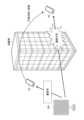
- FIG. 3is a diagram showing an example (3) of NTN.
- NTNis implemented by satellites in space or air vehicles in the air.
- a GEO satellitemay be a satellite located at an altitude of 35,786 km and having a geostationary orbit.
- a LEO satellitemay be a satellite located at an altitude of 500-2000 km and orbiting with a period of 88-127 minutes.
- HAPSHigh Altitude Platform Station
- HAPSHigh Altitude Platform Station
- GEO satellites, LEO satellites and HAPS air vehiclesmay be connected to ground stations gNB via gateways. Also, the service area may increase in order of HAPS, LEO, and GEO.
- NTNcan extend the coverage of 5G networks to unserviced or serviced areas. Also, for example, NTN can improve service continuity, availability and reliability on ships, buses, trains or other critical communications. Note that the NTN may be notified by transmitting a dedicated parameter to the terminal 20, and the dedicated parameter is, for example, based on information related to the satellite or the aircraft. Related to TA (Timing Advance) determination It may be a parameter.
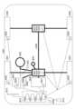
- FIG. 4is a diagram showing an example (4) of NTN.
- FIG. 4shows an example of the NTN network architecture assumed for transparent payloads.
- CNCore Network
- gNB 10CGateway 10B
- Gateway 10Bis connected to satellite 10A via a feeder link.
- Satellite 10Ais connected to terminal 20A or VSAT (Very small aperture terminal) 20B via a service link.
- NR Uuis established between gNB 10C and terminal 20A or VSAT 20B.
- FDDFrequency Division Duplex
- TDDTime Division Duplex
- terrestrial cellsmay be fixed or mobile.
- Terminal 20may also have GNSS (Global Navigation Satellite System) capability.
- FR1may assume a power class 3 handheld device.
- a VSAT devicemay also be assumed, at least in FR2.
- NTN's network architecturemay assume a regenerative payload.
- gNB functionalitymay be onboard a satellite or air vehicle.
- the gNB-DUmay be mounted on a satellite or air vehicle, and the gNB-CU may be deployed as a ground station.
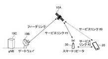
- FIG. 5is a diagram showing an example of NTN in the embodiment of the present invention.
- gNB 10C and terminal 20may communicate via smart repeater 30, as shown in FIG.
- service link #1may be established between satellite 10A and smart repeater 30, and service link #2 may be established between smart repeater 30 and terminal 20.
- service link #0 between satellite 10A and terminal 20may be established as required.
- the terminal 20Since the terminal 20 only needs to communicate with the power that reaches the smart repeater 30, power consumption can be reduced. For example, by reducing power consumption, IoT terminals, RedCap (Reduced capability) terminals, etc. can use the NTN.
- IoT terminals, RedCap (Reduced capability) terminals, etc.can use the NTN.
- the smart repeater 30may be called a wireless relay device 30.
- a wireless communication systemmay include a wireless relay device 30 .
- the radio repeater 30may be a reflector (RIS), a phase control reflector, a passive repeater, an IRS (Intelligent Reflecting Surface), or the like.
- RISReconfigurable Intelligent Surface
- Specific examples of reflectorsmay be those called metamaterial reflectors, dynamic metasurfaces, metasurface lenses, and the like (for example, Non-Patent Document 4).
- the radio relay device 30relays radio signals transmitted from the base station 10A, for example.
- “relay”may refer to at least one of “reflection”, “transmission”, “concentration (concentrating radio waves to approximately one point)", and “diffraction”.
- the terminal 20can receive the radio signal relayed by the radio relay device 30 .
- the radio relay device 30may relay a radio signal transmitted from the terminal 20 or may relay a radio signal transmitted from the base station 10 .
- the radio relay device 30can change the phase of the radio signal relayed to the terminal 20 .
- the radio relay device 30may be called a variable phase reflector.
- the radio relay device 30may have a function of changing the phase of the radio signal and relaying it, but the present invention is not limited to this.
- the wireless relay device 30may be called a repeater, a relay device, a reflect array, an IRS, a transmit array, or the like.
- the wireless relay device 30such as RIS may be called a batteryless device, a metamaterial functional device, an intelligent reflecting surface, a smart repeater, or the like.
- a wireless relay device 30such as a RIS or smart repeater may be defined as having the functions shown in 1)-5) below.
- the signalsmay have a function of receiving signals transmitted from the base station 10 .
- the signalsare DL signals, SSB (SS/PBCH block), PDCCH, PDSCH, DM-RS (Demodulation Reference Signal), PT-RS (Phase Tracking Reference Signal), CSI-RS (Channel Status Information Reference Signal) , RIS dedicated signals, and the like. It may also be capable of receiving signals carrying information relating to metamaterial function. In addition, it may have a transmission function for transmitting the signal to the terminal 20 .
- the signalsmay have a function of transmitting signals to the base station 10 .
- the signalsmay be PRACH, PUCCH, PUSCH, DM-RS, PT-RS, SRS, RIS dedicated signals, etc., which are UL signals. It may have a function of transmitting information related to the metamaterial function. In addition, it may have a reception function for receiving the signal from the terminal 20 .
- Itmay have a frame synchronization function with the base station 10 .
- a frame synchronization function with the terminal 20may be provided.
- the reflection or relay functionis a function related to phase change, a function related to beam control (eg, TCI (Transmission Configuration Indication)-state, QCL (Quasi Co Location) control related function, beam selection application, space selective application of filters/precoding weights).
- the power modification functionmay be power amplification.
- receiving and transmitting and “relaying" in the wireless relay device 30means that although function A below is performed, transmission is performed without performing function B below.
- Function AApply phase shifters and compensation circuits.
- Function BNo frequency conversion is involved.
- the amplitudemay be amplified when the phase is changed in the wireless relay device 30 such as the RIS.
- “relay” in the wireless relay device 30 such as RISmeans transmitting the received signal as it is without performing layer 2 or layer 3 level processing, or transmitting the signal received at the physical layer level as it is. Alternatively, it may mean transmitting the received signal as it is without interpreting the signal (at that time, phase change, amplitude amplification, etc. may be performed).
- the base station 10, the terminal 20, and the radio relay device 30include functions for executing embodiments described later. However, each of the base station 10, the terminal 20 and the radio relay device 30 may have only one of the functions of the embodiments.
- FIG. 6is a diagram showing an example of the functional configuration of the base station 10.
- the base station 10has a transmitting section 110, a receiving section 120, a setting section 130, and a control section 140.
- the functional configuration shown in FIG. 6is merely an example. As long as the operation according to the embodiment of the present invention can be executed, the functional division and the names of the functional units may be arbitrary.
- the transmitting unit 110 and the receiving unit 120may be called a communication unit.
- the transmission unit 110includes a function of generating a signal to be transmitted to the terminal 20 side and wirelessly transmitting the signal.
- the receiving unit 120includes a function of receiving various signals transmitted from the terminal 20 and acquiring, for example, higher layer information from the received signals.
- the transmitting unit 110has a function of transmitting NR-PSS, NR-SSS, NR-PBCH, DL/UL control signals, DL data, etc. to the terminal 20 . Also, the transmission unit 110 transmits setting information and the like to be described in the embodiments.
- the setting unit 130stores preset setting information and various setting information to be transmitted to the terminal 20 in the storage device, and reads them from the storage device as necessary.
- the control unit 140performs, for example, resource allocation, overall control of the base station 10, and the like. It should be noted that the functional unit related to signal transmission in control unit 140 may be included in transmitting unit 110 , and the functional unit related to signal reception in control unit 140 may be included in receiving unit 120 . Also, the transmitting unit 110 and the receiving unit 120 may be called a transmitter and a receiver, respectively.
- FIG. 7is a diagram showing an example of the functional configuration of the terminal 20.
- the terminal 20has a transmitting section 210, a receiving section 220, a setting section 230, and a control section 240.
- the functional configuration shown in FIG. 7is merely an example. As long as the operation according to the embodiment of the present invention can be executed, the functional division and the names of the functional units may be arbitrary.
- the transmitting unit 210 and the receiving unit 220may be called a communication unit.
- the transmission unit 210creates a transmission signal from the transmission data and wirelessly transmits the transmission signal.
- the receiving unit 220wirelessly receives various signals and acquires a higher layer signal from the received physical layer signal. Also, the transmitting unit 210 transmits HARQ (Hybrid automatic repeat request)-ACK, and the receiving unit 220 receives setting information and the like described in the embodiments.
- HARQHybrid automatic repeat request
- the setting unit 230stores various types of setting information received from the base station 10 by the receiving unit 220 in the storage device, and reads them from the storage device as necessary.
- the setting unit 230also stores preset setting information.
- the control unit 240controls the terminal 20 as a whole. It should be noted that the functional unit related to signal transmission in control unit 240 may be included in transmitting unit 210 , and the functional unit related to signal reception in control unit 240 may be included in receiving unit 220 . Also, the transmitting section 210 and the receiving section 220 may be called a transmitter and a receiver, respectively.
- FIG. 8is a diagram showing an example of the functional configuration of the wireless relay device 30 according to the embodiment of the invention.
- the radio relay device 300has a transmission section 310, a reception section 320, a control section 330, a variable section 340 and an antenna section 350.
- FIG.As long as the operation according to the embodiment of the present invention can be executed, the functional division and the names of the functional units may be arbitrary.
- the transmitting unit 310 and the receiving unit 320may be called a communication unit.
- the antenna section 350includes at least one antenna connected to the variable section 340 .
- the antenna section 350may be arranged as an array antenna.
- the antenna section 350may be particularly called a relay antenna.
- the variable section 340 and the antenna section 350may be called a relay section.
- variable section 340is connected to the antenna section 350 and can change the phase, load, amplitude, and the like.
- variable section 340may be a variable phase shifter, phase shifter, amplifier, or the like. For example, by changing the phase of the radio wave that reaches the relay antenna from the radio wave source, the direction or beam of the radio wave can be changed.
- the control unit 330is control means for controlling the variable unit 340 .
- the control unit 330functions as a control unit that controls the relay state when relaying radio waves from the base station 10 or the terminal 20 without signal interpretation.
- the control unit 330may change the relay state based on control information received from the base station 10 or the terminal 20 via the communication unit. to change the relay state. For example, based on control information such as SSB, the control unit 330 may select (directions of) appropriate reception beams and transmission beams and control the variable unit 340 .
- control section 330may select an appropriate combination of reception direction and transmission direction based on criteria such as the highest reception quality or reception power from the reception state, and control variable section 340 .
- the control unit 330includes, for example, information on the propagation path between the terminal 20 or the base station 10A and the antenna unit 350 (including information estimated from the reception state and control information. ), the variable section 340 can be controlled.
- the control unit 330uses a known method such as an active repeater or RIS to change the phase of the radio wave received from the base station 10A without using the transmission power, so that the radio wave receiving destination (in this case, the terminal 20) can be relayed in a specific direction.
- the control unit 330controls the phase of the radio signal for relaying to the terminal 20 or base station 10A.
- the wireless relay device 30controls (changes) only the phase of the wireless signal (radio wave) by the control unit 330, and relays the wireless signal without power supply without amplifying the power of the wireless signal to be relayed. You may
- control unit 330may acquire information according to the reception state. Also, the receiving unit 320 may acquire control information from the base station 10A or the terminal 20 . For example, the receiving unit 320 may receive various signals such as SSB (including various signals exemplified in the functions described above) transmitted from the base station 10A or the terminal 20 as control information.
- SSBincluding various signals exemplified in the functions described above
- control unit 330controls the propagation path between the radio wave source (eg, the base station 10A or the terminal 20) and the antenna unit 350 based on the reception state (eg, change in received power) when the variable unit 340 is controlled.
- InformationH PT and H RP ) may be estimated.
- the propagation path information (propagation channel information) on each propagation pathis specifically information such as amplitude or phase.
- the control unit 330based on the same principle as I/Q (In-phase/Quadrature) detection, changes the received power when switching the phase of the variable unit 340 of the array-shaped antenna unit 350 to orthogonal.
- the propagation path information of the antenna unit 350may be estimated by using the
- FIG. 9is a diagram showing an operation example of the wireless relay device 30 according to the embodiment of the present invention.
- the radio relay device 30is interposed between the base station 10A (other base stations 10 or the like) and the terminal 20, and is interposed between the base station 10A and the terminal 20. relays (reflects, transmits, aggregates, diffracts, etc.) radio signals transmitted and received in
- the base station 10A and the terminal 20directly transmit and receive wireless signals without going through the wireless relay device 30 when the wireless quality is good.
- the radio relay device 30relays radio signals transmitted and received between the base station 10A and the terminal 20. do.
- the radio relay apparatus 30based on the change in the received power during control of the variable unit 340 such as a variable phase shifter, transmits the propagation path information between the radio wave source such as the base station 10A or the terminal 20 and the relay antenna.
- the radio signalis relayed to the radio wave receiving destination such as the terminal 20 .
- the radio relay apparatus 30is not limited to estimating the channel information H PT and H RT , and controls the variable section 340 such as a variable phase shifter based on the control information received from the base station 10A or the terminal 20. Accordingly, the radio signal may be relayed toward the radio wave reception destination such as the base station 10A or the terminal 20.
- a propagation path or a propagation channelis an individual communication path of wireless communication, and here is a communication path between each transmitting/receiving antenna (base station antenna, terminal antenna, etc. in the figure).
- the radio relay apparatus 30includes an antenna section 350 having a small multi-element antenna compatible with Massive MIMO, and a variable phase shifter or phase shifter that changes the phase of a radio signal, substantially a radio wave, to a specific phase. and using the variable unit 340, the phase of the radio wave relayed to the terminal 20 or the base station 10A is controlled.
- FIG. 10is a diagram showing an example of communication in a high frequency band.
- FIG. 10in the case of using a high frequency band of several GHz to several tens of GHz or more, dead zones are likely to occur due to the strong straightness of radio waves.
- the line between the base station 10A and the terminal 20is visible, wireless communication between the base station 10A and the terminal 20 is not affected even when the high frequency band is used.
- the radio qualityis greatly degraded. That is, when the terminal 20 moves to a dead zone blocked by a shield, communication may be interrupted.
- the passive typehas the advantage of not requiring control information, but cannot follow moving objects, environmental changes, and the like.
- the active typerequires control information and has the disadvantage of increasing overhead. Fluctuations and the like can also be followed.
- FBfeedback
- propagation path information normspropagation path information norms.
- the variable radio wave propagation control devicesearches for the optimum condition by having the terminal 20 or the like feed back the communication state when the load (phase) state is changed at random.
- the propagation path information standardthe load state is determined based on the propagation path information between the base station and the radio wave propagation control device, and optimum radio wave propagation control becomes possible. Either type is applicable in the embodiment of the present invention.
- Non-Patent Document 4As relay methods, there are types such as reflection, transmission, diffraction, and consolidation. See Non-Patent Document 4, etc.).
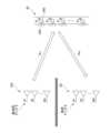
- FIG. 11is a diagram showing an example of the reflective wireless relay device 30 according to the embodiment of the present invention. An example of the system configuration of the reflective radio relay device 30 will be described with reference to FIG. 11 .
- FIG. 11is a diagram showing the relationship between the transmitting antenna Tx of the base station 10A and the like, the relay antenna Sx of the transmissive radio relay device 30, and the receiving antenna Rx of the terminal 20 and the like.
- MIMOis taken as an example, and there are a plurality of propagation paths between Tx-Sx and a plurality of propagation paths between Sx-Rx.
- the device 30relays radio waves by controlling a variable section 340 having a variable phase shifter or the like of the relay antenna Sx.
- the arrayed relay antennasare arranged facing the same direction. Thereby, the propagation path of the relay antenna can be estimated based on the reception state observed when the phase conditions of the relay antenna are changed in a plurality of ways.
- FIG. 12is a diagram showing an example of the transparent wireless relay device 30 according to the embodiment of the present invention. An example of the system configuration of the transparent wireless relay device 30 will be described with reference to FIG. 12 .
- FIG. 12is a diagram showing the relationship among the transmitting antenna Tx of the base station 10A and the like, the relay antenna Sx of the transmissive radio relay device 30, and the receiving antenna Rx of the terminal 20 and the like.
- MIMOis taken as an example, and there are a plurality of propagation paths between Tx and Sx and a plurality of propagation paths between Sx and Rx.
- the relay device 30relays radio waves arriving from one side to the other side via a variable section 340 such as a variable phase shifter of the relay antenna Sx.
- a variable section 340such as a variable phase shifter of the relay antenna Sx.
- the reference antenna on the left side of the figure and the relay antenna on the right side of the figureare paired and directed in opposite directions so that radio waves arriving from one side can be relayed to the other side. are placed.
- a power detector or the likemay be configured to detect the power reaching the relay antenna, and the reception state may be measured. Further, the propagation path of the relay antenna can be estimated based on the received signals observed when the phase conditions of the relay antenna are varied.
- time and frequency synchronizationis performed based on information regarding the position of the terminal 20 and information regarding the position of the satellite 10A and the like.
- the position of satellite 10Amay be shared from gNB 10C to terminal 20 in determining the timing advance (ie, time correction) on the service link.
- the terminal 20may calculate the timing advance based on the position of the satellite 10A shared from the gNB 10C and the position of the own device acquired by GNSS.
- the position of the satellite 10Amay be shared from the gNB 10C to the terminal 20.
- the terminal 20may pre- or post-compensate for frequency Doppler shift based on the shared positions of the satellites 10A from the gNB 10C and its own position obtained by GNSS.
- the method related to synchronizationcannot be used, so extension is required. For example, it may be determined whether smart repeater 30 or terminal 20 performs the time/frequency correction for service link #1 between satellite 10A and smart repeater 30 . Also, a new time/frequency correction method for service link #2 may be defined. In addition, the proper use of UE operation in 3GPP Release 17 may be specified.
- FIG. 13is a diagram for explaining reference points in NTN.
- a reference pointmay be set when calculating the timing advance in the NTN.
- the reference pointmay be set anywhere from the gNB/gateway to the satellite/HAPS, and the network implementation may control the reference point. For example, if the reference point is located on the gNB/gateway side, the implementation of the network will be easier, and if the reference point is located on the satellite/HAPS side, the payload in regenerative NTN or Inter-satellite/ISL Improves backward compatibility with IALs (Inter-aerial links).
- the timing advance TTAmay be represented by the following formula, for example.
- T TA(N TA + N TA, UE-specific + N TA, common + N TA, offset ) x T C
- N TAcommon corresponds to the interval from the reference point to satellite 10A and may be 0 or the value may be broadcast. N TA may be 0 for PRACH, or may be notified to the terminal 20 by the TA command field of Msg2 or MsgB and the TA command field of the TA command of MAC-CE.
- N TA, UE-specificis a self-estimated TA of the delay in the service link section, and may be calculated based on the position of the own device by GNSS, the position of the satellite 10A, and the like.
- N TA,offsetis a fixed offset determined depending on, for example, when bands and LTE/NR coexist.
- Terminal 20may assume that smart repeater 30 applies the timing advance corresponding to service link #1 in FIG. That is, the terminal 20 may apply timing advance corresponding to service link #2 in FIG.
- the terminal 20may apply the timing advance corresponding to the feeder link.
- the timing advance value corresponding to the feeder linkmay be calculated in a manner similar to UE operation in NTNs without smart repeaters 30 (eg 3GPP Release 17).
- FIG. 14is a diagram showing an example (1) of setting TA in the embodiment of the present invention.
- the smart repeater 30when the smart repeater 30 applies the timing advance corresponding to the feeder link, the smart repeater 30 will be pending transmission to the network for a predetermined time after receiving the UL transmission from the terminal 20.
- the UE 20applies TA1 to transmit the UL, and after a delay of 2, the smart repeater 30 receives the UL.
- delay 1corresponds to the propagation delay between the gNB 10C and the smart repeater 30
- delay 2corresponds to the propagation delay between the smart repeater 30 and the terminal 20.
- the smart repeater 30when the smart repeater 30 applies TA2, since the UL from the UE has not been received at the timing to be transmitted, further pending duration (pending duration) after the completion of receiving the UL from the UE , the smart repeater 30 transmits the UL to the gNB 10C, and after a delay of 1, the gNB 10C receives the UL.
- the gNB 10Creceives the UL from the PDCCH at a slot position obtained by adding a hold period to the UL slot offset (that is, the slot offset from PDCCH reception to UL transmission at terminal 20).
- the suspension periodmay be defined by specifications, or may be set or notified to the smart repeater 30 from the network.
- the smart repeater 30receives information (for example, ephemeris data) related to the position of the satellite 10A from the network, and receives this information and information related to its own position (for example, information based on GNSS) may be used to calculate the timing advance value.
- informationfor example, ephemeris data
- information related to its own positionFor example, information based on GNSS
- the method for calculating the timing advance value corresponding to service link #0 in terminal 20may be the same.
- the smart repeater 30may receive information on the timing advance value from the network. For example, smart repeater 30 may calculate the timing advance value for service link #1 using a method similar to the method for calculating the timing advance value for feeder link. If the location of the smart repeater 30 is fixed and the network knows the location, the above method is applicable.
- the terminal 20receives information on the location of the smart repeater 30 from the network, and information on the location of the terminal 20 (for example, GNSS) (based information) may be used to calculate the timing advance value.
- information on the location of the terminal 20for example, GNSS
- the terminal 20may receive information about the timing advance value from the network.
- the informationmay be a TA command in RAR/MAC-CE.
- N TA , N TA, and UE-specific #2are collectively may be treated as an NTA .
- the granularity of the TA commandmay be finer or coarser as compared to TN or 3GPP Release 17 NTN.
- the range that can be indicated by the TA commandmay differ from TN or 3GPP Release 17 NTN.
- the number of bits of the TA commandmay be increased, the granularity of the N TA may be finer, the scaling factor to be applied (for example, multiplied) to the N TA may be further notified, and the N TA may The offset to apply to may be further notified, the conventional TA command bits and further additional bits may be notified, and part of the N TA is notified in the TA command in RAR / MAC-CE , the rest may be signaled in other signaling (eg, SIB, RRC signaling, MAC CE, DCI).
- SIBSIB
- RRC signalinge.g., RRC signaling, MAC CE, DCI
- the timing advance that the smart repeater 30 can grasp and executecan be executed by the smart repeater 30, thereby simplifying the UE operation.
- Terminal 20may apply the timing advance corresponding to service link #1 shown in FIG. That is, the terminal 20 may apply timing advances corresponding to service link #1 and service link #2 shown in FIG.
- TTA(N TA + N TA, UE-specific#1 + N TA, UE-specific #2 + N TA, offset ) x T C
- N TAUE-specific #1 is the timing advance value corresponding to service link #1 shown in FIG.
- N TAUE-specific #2 is the timing advance value corresponding to service link #2 shown in FIG.
- terminal 20applies the timing advance corresponding to service link #1 and service link #2 shown in FIG. 5 and smart repeater 30 applies the timing advance corresponding to the feeder link
- smart repeater 30applies the UL
- transmission to the networkmay be withheld for a predetermined period of time.
- the hold timemay be defined in the specification or notified to the smart repeater 30 by the network.
- the terminal 20may apply the timing advance corresponding to the feeder link.
- the timing advance value corresponding to the feeder linkmay be calculated in a manner similar to UE operation in NTNs without smart repeaters 30 (eg 3GPP Release 17).
- FIG. 15is a diagram showing an example (2) of setting TA in the embodiment of the present invention. As shown in FIG. 15, when terminal 20 applies timing advances corresponding to service link #1, service link #2 and feeder links, smart repeater 30 may not apply timing advances.
- the smart repeater 30receives and transmits the PDCCH after a delay of 1, and the UE 20 receives the PDCCH after a delay of 2.
- the UE 20applies TA and transmits the UL, after delay 2 the smart repeater 30 receives and transmits the UL, and after delay 1 the gNB 10C receives the UL.
- the gNB 10Creceives the UL at the slot position obtained by adding the UL slot offset (that is, the slot offset from the PDCCH reception to the UL transmission at the terminal 20) from the PDCCH.
- the terminal 20may perform the operations shown in the following 1)-3) regarding the calculation of the timing advance value corresponding to the service link #1.
- the terminal 20receives information on the position of the satellite 10A (e.g., ephemeris data) and information on the position of the smart repeater 30 from the network, and receives information on the position of the satellite 10A and the position of the smart repeater 30. information may be used to calculate the timing advance value.
- information on the position of the satellite 10Ae.g., ephemeris data
- information on the position of the smart repeater 30from the network, and receives information on the position of the satellite 10A and the position of the smart repeater 30. information may be used to calculate the timing advance value.
- the location of the smart repeater 30may be a predetermined location and correspond to service link #1 in the same way that a UE without GNSS would calculate the timing advance corresponding to a service link in NTN without the smart repeater 30.
- a timing advance valuemay be calculated.
- terminal 20may calculate the timing advance value corresponding to service link #1 based on the reference position received from gNB 10C. Also, for example, the terminal 20 may receive a timing advance value calculated by the gNB 10C. If the location of the smart repeater 30 is fixed and the network knows the location, the above method is applicable.
- Terminal 20may receive information about the timing advance value from the network. For example, the terminal 20 may calculate the timing advance value corresponding to the service link #1 using a method similar to the method for calculating the timing advance value corresponding to the feeder link. If the location of the smart repeater 30 is fixed and the network knows the location, the above method is applicable.
- the terminal 20may receive the information received from the gNB 10C in 1) or 2) above from the smart repeater 30 and calculate the timing advance value in the same manner as in 1) or 2) above.
- Resources for transmitting signals from smart repeater 30 to terminal 20may be allocated from the network, and any of SSB, PDCCH, and PDSCH may be transmitted. If the smart repeater has a function of transmitting its own information, 3) can be applied.
- the terminal 20receives information on the location of the smart repeater 30 from the network, and information on the location of the terminal 20 (for example, GNSS) (based information) may be used to calculate the timing advance value.
- information on the location of the terminal 20for example, GNSS
- the terminal 20may receive information about the timing advance value from the network.
- the informationmay be a TA command in RAR/MAC-CE.
- N TA , N TA, and UE-specific #2are collectively may be treated as an NTA .
- the granularity of the TA commandmay be finer or coarser as compared to TN or 3GPP Release 17 NTN.
- the range that can be indicated by the TA commandmay differ from TN or 3GPP Release 17 NTN.
- the number of bits of the TA commandmay be increased, the granularity of the N TA may be finer, the scaling factor to be applied (for example, multiplied) to the N TA may be further notified, and the N TA may The offset to apply to may be further notified, the conventional TA command bits and further additional bits may be notified, and part of the N TA is notified in the TA command in RAR / MAC-CE , the rest may be signaled in other signaling (eg, SIB, RRC signaling, MAC CE, DCI).
- SIBSIB
- RRC signalinge.g., RRC signaling, MAC CE, DCI
- the terminal 20can appropriately apply the timing advance by calculating the timing advance value corresponding to the service link #1 shown in FIG.
- the smart repeater 30does not need to suspend UL transmission, and the configuration of the smart repeater 30 can be simplified.
- the smart repeater 30may perform DL post-compensation and UL pre-compensation.
- the smart repeater 30receives information on the position of the satellite 10A from the network (e.g., ephemeris data), and uses the information and information on the position of its own device (e.g., information based on GNSS) to calculate the Doppler shift value. can be calculated.
- the method for calculating the Doppler shift value corresponding to service link #0 in terminal 20may be the same.
- the smart repeater 30may receive information related to the Doppler shift compensation from the network. For example, using a method similar to that for calculating the timing advance value for feeder link, smart repeater 30 may calculate the Doppler shift value for service link #1 of interest. If the location of the smart repeater 30 is fixed and the network knows the location, the above method is applicable.
- the operation of the terminal 20can be simplified.
- the terminal 20may assume that the network applies Doppler shift compensation corresponding to service link #1. That is, the terminal 20 does not need to perform DL post-compensation and UL pre-compensation.
- Terminal 20may apply Doppler shift compensation as indicated in 1)-3) below.
- the terminal 20may receive information (e.g., ephemeris data) on the position of the satellite 10A from the network, and use this information and information on the position of the smart repeater 30 to calculate the timing advance value. .
- informatione.g., ephemeris data
- the location of smart repeater 30may be a predetermined location and correspond to service link #1 in the same way that a UE without GNSS would calculate the Doppler shift value corresponding to a service link in NTN without smart repeater 30. A Doppler shift value may be calculated. If the location of the smart repeater 30 is fixed and the network knows the location, the above method is applicable.
- the terminal 20may receive information about the Doppler shift value from the network. If the location of the smart repeater 30 is fixed and the network knows the location, the above method is applicable.
- the terminal 20may receive the information received from the gNB 10C in 1) or 2) above from the smart repeater 30 and calculate the Doppler shift value in the same manner as in 1) or 2) above.
- Resources for transmitting signals from smart repeater 30 to terminal 20may be allocated from the network, and any of SSB, PDCCH, and PDSCH may be transmitted. If the smart repeater has a function of transmitting its own information, 3) can be applied.
- the Doppler shift compensationcan be appropriately applied. Also, the configuration of the smart repeater 30 can be simplified since it is not necessary to perform Doppler shift compensation in the smart repeater 30 .
- the terminal 20may operate as indicated in 1)-3) below regarding whether communication is routed through the smart repeater 30 or not.
- the terminal 20may determine whether or not the smart repeater 30 is present. For example, the terminal 20 may change the UE behavior based on whether or not the smart repeater 30 is routed. For example, the terminal 20 may determine whether or not it is via the smart repeater 30 based on the SS index. For example, the terminal 20 may determine the presence or absence of the smart repeater 30 based on the MIB or SIB. For example, the terminal 20 may determine the presence or absence of the smart repeater 30 based on a predetermined parameter.
- the terminal 20may determine whether or not the smart repeater 30 is present.
- Resources for transmitting signals from smart repeater 30 to terminal 20may be allocated from the network, and any of SSB, PDCCH, and PDSCH may be transmitted. This can be applied when the smart repeater 30 has a function of transmitting its own information.
- the terminal 20may send to the network a UE capability indicating whether or not NTN communication via the smart repeater 30 is possible.
- the terminal 20By executing the operation related to whether or not the smart repeater 30 is routed as described above, it is determined which of the UE operation in NTN and the UE operation in the embodiment of the present invention is applied, and the terminal 20 operates appropriately. can be done.
- the terminal 20can determine the timing advance value to be applied to communication via the smart repeater 30 in the NTN environment.
- each functional blockmay be implemented using one device that is physically or logically coupled, or directly or indirectly using two or more devices that are physically or logically separated (e.g. , wired, wireless, etc.) and may be implemented using these multiple devices.
- a functional blockmay be implemented by combining software in the one device or the plurality of devices.
- Functionsinclude judging, determining, determining, calculating, calculating, processing, deriving, investigating, searching, checking, receiving, transmitting, outputting, accessing, resolving, selecting, choosing, establishing, comparing, assuming, expecting, assuming, broadcasting, notifying, communicating, forwarding, configuring, reconfiguring, allocating, mapping, assigning, etc. can't
- a functional block (component) responsible for transmissionis called a transmitting unit or transmitter.
- the implementation methodis not particularly limited.
- the base station 10, the terminal 20, the wireless relay device 30, and the likemay function as computers that perform processing of the wireless communication method of the present disclosure.
- FIG. 16is a diagram illustrating an example of hardware configurations of the base station 10, terminal 20, and radio relay device 30 according to an embodiment of the present disclosure.
- the base station 10, the terminal 20, and the wireless relay device 30 described aboveare physically computers including a processor 1001, a storage device 1002, an auxiliary storage device 1003, a communication device 1004, an input device 1005, an output device 1006, a bus 1007, and the like. It may be configured as a device.
- the term "apparatus”can be read as a circuit, device, unit, or the like.
- the hardware configuration of the base station 10, the terminal 20, and the radio relay device 30may be configured to include one or more of each device shown in the figure, or may be configured without some devices. good.
- Each function of the base station 10, the terminal 20, and the radio relay device 30is performed by the processor 1001 by loading predetermined software (program) onto hardware such as the processor 1001 and the storage device 1002, and the communication device 1004. It is realized by controlling communication via the storage device 1002 and controlling at least one of data reading and writing in the storage device 1002 and the auxiliary storage device 1003 .
- the processor 1001for example, operates an operating system and controls the entire computer.
- the processor 1001may be configured with a central processing unit (CPU) including an interface with peripheral devices, a control device, an arithmetic device, registers, and the like.
- CPUcentral processing unit
- the control unit 140 , the control unit 240 and the like described abovemay be implemented by the processor 1001 .
- the processor 1001reads programs (program codes), software modules, data, etc. from at least one of the auxiliary storage device 1003 and the communication device 1004 to the storage device 1002, and executes various processes according to them.
- programsprogram codes
- software modulessoftware modules
- dataetc.
- the programa program that causes a computer to execute at least part of the operations described in the above embodiments is used.
- control unit 140 of base station 10 shown in FIG. 2may be implemented by a control program stored in storage device 1002 and operated by processor 1001 .
- FIG. Processor 1001may be implemented by one or more chips.
- the programmay be transmitted from a network via an electric communication line.
- the storage device 1002is a computer-readable recording medium, for example, ROM (Read Only Memory), EPROM (Erasable Programmable ROM), EEPROM (Electrically Erasable Programmable ROM), RAM (Random Access Memory), etc. may be configured.
- the storage device 1002may also be called a register, cache, main memory (main storage device), or the like.
- the storage device 1002can store executable programs (program code), software modules, etc. for implementing a communication method according to an embodiment of the present disclosure.
- the auxiliary storage device 1003is a computer-readable recording medium, for example, an optical disc such as a CD-ROM (Compact Disc ROM), a hard disk drive, a flexible disc, a magneto-optical disc (for example, a compact disc, a digital versatile disc, a Blu -ray disk), smart card, flash memory (eg, card, stick, key drive), floppy disk, magnetic strip, and/or the like.
- the storage medium described abovemay be, for example, a database, server, or other suitable medium including at least one of storage device 1002 and secondary storage device 1003 .
- the communication device 1004is hardware (transmitting/receiving device) for communicating between computers via at least one of a wired network and a wireless network, and is also called a network device, a network controller, a network card, a communication module, or the like.
- the communication device 1004includes a high-frequency switch, a duplexer, a filter, a frequency synthesizer, etc. in order to realize at least one of, for example, frequency division duplex (FDD) and time division duplex (TDD).
- FDDfrequency division duplex
- TDDtime division duplex
- the transceivermay be physically or logically separate implementations for the transmitter and receiver.
- the input device 1005is an input device (for example, keyboard, mouse, microphone, switch, button, sensor, etc.) that receives input from the outside.
- the output device 1006is an output device (for example, display, speaker, LED lamp, etc.) that outputs to the outside. Note that the input device 1005 and the output device 1006 may be integrated (for example, a touch panel).
- Each devicesuch as the processor 1001 and the storage device 1002 is connected by a bus 1007 for communicating information.
- the bus 1007may be configured using a single bus, or may be configured using different buses between devices.
- the base station 10, the terminal 20, and the radio relay device 30include microprocessors, digital signal processors (DSPs), ASICs (Application Specific Integrated Circuits), PLDs (Programmable Logic Devices), FPGAs (Field Programmable Gate ), etc., and part or all of each functional block may be realized by the hardware.
- DSPsdigital signal processors
- ASICsApplication Specific Integrated Circuits
- PLDsProgrammable Logic Devices
- FPGAsField Programmable Gate
- the radio relay device 30may have a variable phase shifter, a phase shifter, an amplifier, an antenna, an array antenna, etc., as hardware constituting the variable section 340 and the antenna section 350, if necessary.
- a vehicle 2001includes a drive section 2002, a steering section 2003, an accelerator pedal 2004, a brake pedal 2005, a shift lever 2006, front wheels 2007, rear wheels 2008, an axle 2009, an electronic control section 2010, and various sensors 2021 to 2029. , an information service unit 2012 and a communication module 2013 .
- Each aspect/embodiment described in the present disclosuremay be applied to a communication device mounted on vehicle 2001, and may be applied to communication module 2013, for example.
- the driving unit 2002is configured by, for example, an engine, a motor, or a hybrid of the engine and the motor.
- the steering unit 2003includes at least a steering wheel (also referred to as steering wheel), and is configured to steer at least one of the front wheels and the rear wheels based on the operation of the steering wheel operated by the user.
- the electronic control unit 2010is composed of a microprocessor 2031 , a memory (ROM, RAM) 2032 and a communication port (IO port) 2033 . Signals from various sensors 2021 to 2029 provided in the vehicle 2001 are input to the electronic control unit 2010 .
- the electronic control unit 2010may also be called an ECU (Electronic Control Unit).
- the signals from the various sensors 2021 to 2029include the current signal from the current sensor 2021 that senses the current of the motor, the rotation speed signal of the front and rear wheels acquired by the rotation speed sensor 2022, and the front wheel acquired by the air pressure sensor 2023. and rear wheel air pressure signal, vehicle speed signal obtained by vehicle speed sensor 2024, acceleration signal obtained by acceleration sensor 2025, accelerator pedal depression amount signal obtained by accelerator pedal sensor 2029, brake pedal sensor 2026 obtained by There are a brake pedal depression amount signal, a shift lever operation signal acquired by the shift lever sensor 2027, and a detection signal for detecting obstacles, vehicles, pedestrians, etc. acquired by the object detection sensor 2028, and the like.
- the information service unit 2012includes various devices such as car navigation systems, audio systems, speakers, televisions, and radios for providing various types of information such as driving information, traffic information, and entertainment information, and one or more devices for controlling these devices. ECU.
- the information service unit 2012uses information acquired from an external device via the communication module 2013 or the like to provide passengers of the vehicle 2001 with various multimedia information and multimedia services.
- Driving support system unit 2030includes millimeter wave radar, LiDAR (Light Detection and Ranging), camera, positioning locator (e.g., GNSS, etc.), map information (e.g., high-definition (HD) map, automatic driving vehicle (AV) map, etc. ), gyro systems (e.g., IMU (Inertial Measurement Unit), INS (Inertial Navigation System), etc.), AI (Artificial Intelligence) chips, AI processors, etc., to prevent accidents and reduce the driver's driving load. and one or more ECUs for controlling these devices.
- the driving support system unit 2030transmits and receives various information via the communication module 2013, and realizes a driving support function or an automatic driving function.
- the communication module 2013can communicate with the microprocessor 2031 and components of the vehicle 2001 via communication ports.
- the communication module 2013communicates with the vehicle 2001 through the communication port 2033, the drive unit 2002, the steering unit 2003, the accelerator pedal 2004, the brake pedal 2005, the shift lever 2006, the front wheels 2007, the rear wheels 2008, the axle 2009, the electronic Data is transmitted and received between the microprocessor 2031 and memory (ROM, RAM) 2032 in the control unit 2010 and the sensors 2021-29.
- the communication module 2013is a communication device that can be controlled by the microprocessor 2031 of the electronic control unit 2010 and can communicate with an external device. For example, it transmits and receives various information to and from an external device via wireless communication.
- Communication module 2013may be internal or external to electronic control unit 2010 .
- the external devicemay be, for example, a base station, a mobile station, or the like.
- the communication module 2013transmits the current signal from the current sensor input to the electronic control unit 2010 to an external device via wireless communication.
- the communication module 2013receives the rotation speed signal of the front and rear wheels obtained by the rotation speed sensor 2022, the air pressure signal of the front and rear wheels obtained by the air pressure sensor 2023, and the vehicle speed sensor. 2024, an acceleration signal obtained by an acceleration sensor 2025, an accelerator pedal depression amount signal obtained by an accelerator pedal sensor 2029, a brake pedal depression amount signal obtained by a brake pedal sensor 2026, and a shift lever.
- a shift lever operation signal obtained by the sensor 2027 and a detection signal for detecting obstacles, vehicles, pedestrians, etc. obtained by the object detection sensor 2028are also transmitted to an external device via wireless communication.
- the communication module 2013receives various information (traffic information, signal information, inter-vehicle information, etc.) transmitted from external devices, and displays it on the information service unit 2012 provided in the vehicle 2001 .
- Communication module 2013also stores various information received from external devices in memory 2032 available to microprocessor 2031 .
- the microprocessor 2031controls the drive unit 2002, the steering unit 2003, the accelerator pedal 2004, the brake pedal 2005, the shift lever 2006, the front wheels 2007, the rear wheels 2008, and the axle 2009 provided in the vehicle 2001.
- sensors 2021 to 2029 and the likemay be controlled.
- a base stationthat constitutes an NTN (Non-Terrestrial Network), a communication unit that communicates via a non-terrestrial device and a wireless relay device, A first timing advance value corresponding to a section from the non-ground device to the radio relay device and a section from the radio relay device to the device, in a link from the non-ground device to the device itself. and a controller for applying at least one of a second timing advance value to said communication.
- NTNNon-Terrestrial Network
- the terminal 20can determine the timing advance value to be applied to communication via the smart repeater 30 in the NTN environment. That is, in the wireless communication system, it is possible to appropriately set the timing advance value applied to communication via the wireless relay device.
- the control unitdoes not apply the first timing advance value to the communication, applies the second timing advance value to the communication, and applies the second timing advance value to a link from the base station to the non-terrestrial device.
- a timing advance value of 3may not be applied to the communication.
- the terminal 20can determine the timing advance value to be applied to communication via the smart repeater 30 in the NTN environment.
- a second timing advance valuemay be calculated.
- the terminal 20can determine the timing advance value to be applied to communication via the smart repeater 30 in the NTN environment.
- the control unitmay apply the first timing advance value to the communication and apply the second timing advance value to the communication.
- the terminal 20can determine the timing advance value to be applied to communication via the smart repeater 30 in the NTN environment.
- the terminal 20can determine the timing advance value to be applied to communication via the smart repeater 30 in the NTN environment.
- a base stationconstituting a NTN (Non-Terrestrial Network), a communication procedure for communicating via a non-terrestrial device and a wireless relay device, and from the non-terrestrial device A first timing advance value corresponding to a section from the non-terrestrial device to the wireless relay device and a second timing advance value corresponding to a section from the wireless relay device to the self device in the link to the self device. and a control procedure for applying at least one of a value to said communication.
- NTNNon-Terrestrial Network
- the terminal 20can determine the timing advance value to be applied to communication via the smart repeater 30 in the NTN environment. That is, in the wireless communication system, it is possible to appropriately set the timing advance value applied to communication via the wireless relay device.
- the operations of a plurality of functional unitsmay be physically performed by one component, or the operations of one functional unit may be physically performed by a plurality of components.
- the processing ordermay be changed as long as there is no contradiction.
- the base station 10 and the terminal 20have been described using functional block diagrams for convenience of explanation of processing, such devices may be implemented in hardware, software, or a combination thereof.
- the software operated by the processor of the base station 10 according to the embodiment of the present invention and the software operated by the processor of the terminal 20 according to the embodiment of the present inventionare stored in random access memory (RAM), flash memory, read-only memory, respectively. (ROM), EPROM, EEPROM, register, hard disk (HDD), removable disk, CD-ROM, database, server, or any other appropriate storage medium.
- notification of informationis not limited to the aspects/embodiments described in the present disclosure, and may be performed using other methods.
- notification of informationincludes physical layer signaling (e.g., DCI (Downlink Control Information), UCI (Uplink Control Information)), higher layer signaling (e.g., RRC (Radio Resource Control) signaling, MAC (Medium Access Control) signaling, It may be implemented by broadcast information (MIB (Master Information Block), SIB (System Information Block)), other signals, or a combination thereof.
- RRC signalingmay also be called an RRC message, for example, RRC It may be a connection setup (RRC Connection Setup) message, an RRC connection reconfiguration message, or the like.
- Each aspect/embodiment described in the present disclosureincludes LTE (Long Term Evolution), LTE-A (LTE-Advanced), SUPER 3G, IMT-Advanced, 4G (4th generation mobile communication system), 5G (5th generation mobile communication system) system), 6th generation mobile communication system (6G), xth generation mobile communication system (xG) (xG (x is, for example, an integer, a decimal number)), FRA (Future Radio Access), NR (new Radio), New radio access ( NX), Future generation radio access (FX), W-CDMA (registered trademark), GSM (registered trademark), CDMA2000, UMB (Ultra Mobile Broadband), IEEE 802.11 (Wi-Fi (registered trademark)), IEEE 802 .16 (WiMAX (registered trademark)), IEEE 802.20, UWB (Ultra-WideBand), Bluetooth (registered trademark), and other suitable systems, and any extensions, modifications, creations, and provisions based on these systems. It may be applied to
- a specific operation performed by the base station 10 in this specificationmay be performed by its upper node in some cases.
- various operations performed for communication with terminal 20may be performed by base station 10 and other network nodes other than base station 10 (eg, but not limited to MME or S-GW).
- base station 10e.g, but not limited to MME or S-GW
- the other network nodemay be a combination of a plurality of other network nodes (for example, MME and S-GW).
- Information, signals, etc. described in the present disclosuremay be output from a higher layer (or a lower layer) to a lower layer (or a higher layer). It may be input and output via multiple network nodes.
- Input/output informationmay be stored in a specific location (for example, memory) or managed using a management table. Input/output information and the like can be overwritten, updated, or appended. The output information and the like may be deleted. The entered information and the like may be transmitted to another device.
- the determination in the present disclosuremay be performed by a value represented by 1 bit (0 or 1), may be performed by a boolean value (Boolean: true or false), or may be performed by comparing numerical values (e.g. , comparison with a predetermined value).
- Softwarewhether referred to as software, firmware, middleware, microcode, hardware description language or otherwise, includes instructions, instruction sets, code, code segments, program code, programs, subprograms, and software modules. , applications, software applications, software packages, routines, subroutines, objects, executables, threads of execution, procedures, functions, and the like.
- software, instructions, information, etc.may be transmitted and received via a transmission medium.
- the softwareuses at least one of wired technology (coaxial cable, fiber optic cable, twisted pair, digital subscriber line (DSL), etc.) and wireless technology (infrared, microwave, etc.) to website, Wired and/or wireless technologies are included within the definition of transmission medium when sent from a server or other remote source.
- wired technologycoaxial cable, fiber optic cable, twisted pair, digital subscriber line (DSL), etc.
- wireless technologyinfrared, microwave, etc.
- data, instructions, commands, information, signals, bits, symbols, chips, etc.may refer to voltages, currents, electromagnetic waves, magnetic fields or magnetic particles, light fields or photons, or any of these. may be represented by a combination of
- the channel and/or symbolsmay be signaling.
- a signalmay also be a message.
- a component carriermay also be called a carrier frequency, a cell, a frequency carrier, or the like.
- systemand “network” used in this disclosure are used interchangeably.
- information, parameters, etc. described in the present disclosuremay be expressed using absolute values, may be expressed using relative values from a predetermined value, or may be expressed using other corresponding information.
- radio resourcesmay be indexed.
- base stationBS
- radio base stationbase station
- base station devicefixed station
- NodeBNodeB
- eNodeBeNodeB
- gNodeBgNodeB
- a base stationcan accommodate one or more (eg, three) cells.
- the overall coverage area of the base stationcan be partitioned into multiple smaller areas, each smaller area being associated with a base station subsystem (e.g., an indoor small base station (RRH:
- RRHindoor small base station
- the term "cell” or “sector”refers to part or all of the coverage area of at least one of the base stations and base station subsystems serving communication services in this coverage.
- MSMobile Station
- UEUser Equipment
- a mobile stationis defined by those skilled in the art as a subscriber station, mobile unit, subscriber unit, wireless unit, remote unit, mobile device, wireless device, wireless communication device, remote device, mobile subscriber station, access terminal, mobile terminal, wireless It may also be called a terminal, remote terminal, handset, user agent, mobile client, client, or some other suitable term.
- At least one of the base station and mobile stationmay be called a transmitting device, a receiving device, a communication device, or the like.
- At least one of the base station and the mobile stationmay be a device mounted on a mobile object, the mobile object itself, or the like.
- the mobile objectmay be a vehicle (e.g., car, airplane, etc.), an unmanned mobile object (e.g., drone, self-driving car, etc.), or a robot (manned or unmanned ).
- at least one of the base station and the mobile stationincludes devices that do not necessarily move during communication operations.
- at least one of the base station and mobile stationmay be an IoT (Internet of Things) device such as a sensor.
- IoTInternet of Things
- the base station in the present disclosuremay be read as a user terminal.
- communication between a base station and a user terminalis replaced with communication between a plurality of terminals 20 (for example, D2D (Device-to-Device), V2X (Vehicle-to-Everything), etc.)
- the terminal 20may have the functions of the base station 10 described above.
- words such as "up” and “down”may be replaced with words corresponding to inter-terminal communication (for example, "side”).
- uplink channels, downlink channels, etc.may be read as side channels.
- user terminals in the present disclosuremay be read as base stations.
- the base stationmay have the functions that the above-described user terminal has.
- determiningand “determining” used in this disclosure may encompass a wide variety of actions.
- “Judgement” and “determination”are, for example, judging, calculating, computing, processing, deriving, investigating, looking up, searching, inquiring (eg, lookup in a table, database, or other data structure), ascertaining as “judged” or “determined”, and the like.
- "judgment” and “determination”are used for receiving (e.g., receiving information), transmitting (e.g., transmitting information), input, output, access (accessing) (for example, accessing data in memory) may include deeming that a "judgment” or “decision” has been made.
- judgment and “decision”are considered to be “judgment” and “decision” by resolving, selecting, choosing, establishing, comparing, etc. can contain.
- judgment and “decision”may include considering that some action is “judgment” and “decision”.
- judgment (decision)may be read as “assuming”, “expecting”, “considering”, or the like.
- connectionmeans any direct or indirect connection or coupling between two or more elements, It can include the presence of one or more intermediate elements between two elements being “connected” or “coupled.” Couplings or connections between elements may be physical, logical, or a combination thereof. For example, “connection” may be read as "access”.
- two elementsare defined using at least one of one or more wires, cables, and printed electrical connections and, as some non-limiting and non-exhaustive examples, in the radio frequency domain. , electromagnetic energy having wavelengths in the microwave and optical (both visible and invisible) regions, and the like.
- the reference signalcan also be abbreviated as RS (Reference Signal), and may also be called Pilot depending on the applicable standard.
- RSReference Signal
- any reference to elements using the "first,” “second,” etc. designations used in this disclosuredoes not generally limit the quantity or order of those elements. These designations may be used in this disclosure as a convenient method of distinguishing between two or more elements. Thus, reference to a first and second element does not imply that only two elements can be employed or that the first element must precede the second element in any way.
- a radio framemay consist of one or more frames in the time domain. Each frame or frames in the time domain may be referred to as a subframe. A subframe may also consist of one or more slots in the time domain. A subframe may be of a fixed length of time (eg, 1 ms) independent of numerology.
- a numerologymay be a communication parameter that applies to the transmission and/or reception of a signal or channel. Numerology, for example, subcarrier spacing (SCS), bandwidth, symbol length, cyclic prefix length, transmission time interval (TTI), number of symbols per TTI, radio frame configuration, transceiver It may indicate at least one of certain filtering operations performed in the frequency domain, certain windowing operations performed by the transceiver in the time domain, and/or the like.
- SCSsubcarrier spacing
- TTItransmission time interval
- transceiverIt may indicate at least one of certain filtering operations performed in the frequency domain, certain windowing operations performed by the transceiver in the time domain, and/or the like.
- a slotmay consist of one or more symbols (OFDM (Orthogonal Frequency Division Multiplexing) symbol, SC-FDMA (Single Carrier Frequency Division Multiple Access) symbol, etc.) in the time domain.
- a slotmay be a unit of time based on numerology.
- a slotmay contain multiple mini-slots. Each minislot may consist of one or more symbols in the time domain. A minislot may also be referred to as a subslot. A minislot may consist of fewer symbols than a slot.
- PDSCH (or PUSCH) transmitted in time units larger than minislotsmay be referred to as PDSCH (or PUSCH) mapping type A.
- PDSCH (or PUSCH) transmitted using minislotsmay be referred to as PDSCH (or PUSCH) mapping type B.
- Radio frames, subframes, slots, minislots and symbolsall represent time units when transmitting signals. Radio frames, subframes, slots, minislots and symbols may be referred to by other corresponding designations.
- one subframemay be called a Transmission Time Interval (TTI)
- TTITransmission Time Interval
- TTITransmission Time Interval
- TTITransmission Time Interval
- one slot or one minislotmay be called a TTI.
- TTITransmission Time Interval
- at least one of the subframe and TTImay be a subframe (1 ms) in existing LTE, a period shorter than 1 ms (eg, 1-13 symbols), or a period longer than 1 ms may be Note that the unit representing the TTI may be called a slot, mini-slot, or the like instead of a subframe.
- TTIrefers to, for example, the minimum scheduling time unit in wireless communication.
- the base stationperforms scheduling to allocate radio resources (frequency bandwidth, transmission power, etc. that can be used by each terminal 20) to each terminal 20 on a TTI basis.
- radio resourcesfrequency bandwidth, transmission power, etc. that can be used by each terminal 20
- TTIis not limited to this.
- a TTImay be a transmission time unit such as a channel-encoded data packet (transport block), code block, or codeword, or may be a processing unit such as scheduling and link adaptation. Note that when a TTI is given, the time interval (for example, the number of symbols) in which transport blocks, code blocks, codewords, etc. are actually mapped may be shorter than the TTI.
- one or more TTIsmay be the minimum scheduling time unit. Also, the number of slots (the number of mini-slots) constituting the minimum time unit of the scheduling may be controlled.
- a TTI having a time length of 1 msmay be called a normal TTI (TTI in LTE Rel. 8-12), normal TTI, long TTI, normal subframe, normal subframe, long subframe, slot, or the like.
- a TTI that is shorter than a normal TTImay be called a shortened TTI, a short TTI, a partial or fractional TTI, a shortened subframe, a short subframe, a minislot, a subslot, a slot, and the like.
- the long TTI(e.g., normal TTI, subframe, etc.) may be replaced with a TTI having a time length exceeding 1 ms
- the short TTIe.g., shortened TTI, etc.
- a TTI having the above TTI lengthmay be read instead.
- a resource blockis a resource allocation unit in the time domain and the frequency domain, and may include one or more consecutive subcarriers in the frequency domain.
- the number of subcarriers included in the RBmay be the same regardless of the numerology, and may be 12, for example.
- the number of subcarriers included in an RBmay be determined based on numerology.
- the time domain of an RBmay include one or more symbols and may be 1 slot, 1 minislot, 1 subframe, or 1 TTI long.
- One TTI, one subframe, etc.may each consist of one or more resource blocks.
- One or more RBsare physical resource blocks (PRBs), sub-carrier groups (SCGs), resource element groups (REGs), PRB pairs, RB pairs, etc. may be called.
- PRBsphysical resource blocks
- SCGssub-carrier groups
- REGsresource element groups
- PRB pairsRB pairs, etc. may be called.
- a resource blockmay be composed of one or more resource elements (RE: Resource Element).
- REResource Element
- 1 REmay be a radio resource region of 1 subcarrier and 1 symbol.
- a bandwidth part(which may also be called a bandwidth part) may represent a subset of contiguous common resource blocks (RBs) for a certain numerology on a certain carrier.
- the common RBmay be identified by an RB index based on the common reference point of the carrier.
- PRBsmay be defined in a BWP and numbered within that BWP.
- the BWPmay include a BWP for UL (UL BWP) and a BWP for DL (DL BWP).
- UL BWPUL BWP
- DL BWPDL BWP
- One or multiple BWPsmay be configured for a UE within one carrier.
- At least one of the configured BWPsmay be active, and the UE may not expect to transmit or receive a given signal/channel outside the active BWP.
- BWPbitmap
- radio frames, subframes, slots, minislots and symbols described aboveare only examples.
- the number of subframes contained in a radio framethe number of slots per subframe or radio frame, the number of minislots contained within a slot, the number of symbols and RBs contained in a slot or minislot, the number of Configurations such as the number of subcarriers, the number of symbols in a TTI, the symbol length, the cyclic prefix (CP) length, etc.
- CPcyclic prefix
- a and B are differentmay mean “A and B are different from each other.”
- the termmay also mean that "A and B are different from C”.
- Terms such as “separate,” “coupled,” etc.may also be interpreted in the same manner as “different.”
- notification of predetermined informationis not limited to being performed explicitly, but may be performed implicitly (for example, not notifying the predetermined information). good too.
- base station 110transmitting unit 120 receiving unit 130 setting unit 140 control unit 20 terminal 210 transmitting unit 220 receiving unit 230 setting unit 240 control unit 30 radio relay device 310 transmitting unit 320 receiving unit 330 control unit 340 variable unit 350 antenna unit 1001 processor 1002 Storage device 1003 Auxiliary storage device 1004 Communication device 1005 Input device 1006 Output device 2001 Vehicle 2002 Driving unit 2003 Steering unit 2004 Accelerator pedal 2005 Brake pedal 2006 Shift lever 2007 Front wheel 2008 Rear wheel 2009 Axle 2010 Electronic control unit 2012 Information service unit 2013 Communication Module 2021 Current sensor 2022 Revolution sensor 2023 Air pressure sensor 2024 Vehicle speed sensor 2025 Acceleration sensor 2026 Brake pedal sensor 2027 Shift lever sensor 2028 Object detection sensor 2029 Accelerator pedal sensor 2030 Driving support system unit 2031 Microprocessor 2032 Memory (ROM, RAM) 2033 communication port (IO port)
Landscapes
- Engineering & Computer Science (AREA)
- Computer Networks & Wireless Communication (AREA)
- Signal Processing (AREA)
- Physics & Mathematics (AREA)
- Astronomy & Astrophysics (AREA)
- Aviation & Aerospace Engineering (AREA)
- General Physics & Mathematics (AREA)
- Mobile Radio Communication Systems (AREA)
- Radio Relay Systems (AREA)
Abstract
Description
Translated fromJapanese本発明は、無線通信システムにおける端末及び通信方法に関する。The present invention relates to a terminal and communication method in a wireless communication system.
LTE(Long Term Evolution)の後継システムであるNR(New Radio)(「5G」ともいう。)においては、要求条件として、大容量のシステム、高速なデータ伝送速度、低遅延、多数の端末の同時接続、低コスト、省電力等を満たす技術が検討されている(例えば非特許文献1)。NR (New Radio) (also called "5G"), which is the successor system to LTE (Long Term Evolution), requires a large-capacity system, high data transmission speed, low latency, and the simultaneous use of many terminals. Techniques satisfying connection, low cost, power saving, etc. are being studied (for example, Non-Patent Document 1).
現在、NTN(Non-Terrestrial Network)が検討されている。NTNとは、衛星等の非地上型ネットワークを使用して、地上型5Gネットワークでは主にコスト面でカバーできないエリアにサービスを提供するものである(例えば非特許文献2及び非特許文献3)。The NTN (Non-Terrestrial Network) is currently being considered. NTN uses non-terrestrial networks such as satellites to provide services to areas that cannot be covered by terrestrial 5G networks mainly due to cost (for example, Non-Patent
また、次世代通信では、高周波数帯の使用が見込まれている。当該高周波数帯の特性による、散乱体数の減少、シャドーウィング効果の低下及び距離減衰の増加等の観点から、通信品質の改善が要求される。通信品質を担保するビーム制御及び環境等が必要とされると想定される。In addition, next-generation communications are expected to use high frequency bands. Improvements in communication quality are required from the viewpoint of reducing the number of scatterers, reducing shadowing effects, increasing distance attenuation, etc., due to the characteristics of the high frequency band. It is assumed that beam control and environment etc. to ensure communication quality will be required.
例えば、高周波数帯域では、電波の強い直進性等によって、不感地帯が発生しやすい問題がある。そこで、パッシブなリピータ又はアクティブ型の反射板(RIS:Reconfigurable Intelligent Surface)、信号を受信及び増幅し再放射するスマートリピータ等を用いて、マルチパス環境下において、通信品質を改善させる方法が試行されている(例えば非特許文献4)。For example, in high frequency bands, there is a problem that dead zones are likely to occur due to the strong straightness of radio waves. Therefore, attempts have been made to improve communication quality in a multipath environment using passive repeaters, active reflectors (RIS: Reconfigurable Intelligent Surface), and smart repeaters that receive, amplify, and re-radiate signals. (For example, Non-Patent Document 4).
NTNでは、上空の基地局と端末間の距離が非常に大きいため、伝搬遅延が地上型ネットワーク(Terrestrial Network, TN)と比較して大きくなる。また、NTNではフィーダリンク及びサービスリンクを介して通信が実行されるため、従来の地上型ネットワークと比較してTA(Timing Advance)は非常に大きくなり、当該伝搬遅延を考慮した設定が必要となる。さらに、スマートリピータをサービスリンクに使用する場合、上空の基地局とスマートリピータ間の遅延及びスマートリピータと端末間の遅延をTA決定時に考慮する必要がある。In NTN, the distance between base stations and terminals in the sky is very large, so the propagation delay is larger than in terrestrial networks (Terrestrial Network, TN). In addition, since NTN communicates via feeder links and service links, TA (Timing Advance) is much larger than conventional terrestrial networks, and it is necessary to set up considering the propagation delay. . In addition, when smart repeaters are used for service links, the delay between the base station in the sky and the smart repeater and the delay between the smart repeater and the terminal must be considered when determining TA.
本発明は上記の点に鑑みてなされたものであり、無線通信システムにおいて、無線中継装置を経由する通信に適用されるタイミングアドバンス値を適切に設定することを目的とする。The present invention has been made in view of the above points, and an object of the present invention is to appropriately set a timing advance value applied to communication via a wireless relay device in a wireless communication system.
開示の技術によれば、NTN(Non-Terrestrial Network)を構成する基地局と、非地上の装置及び無線中継装置を介して通信を行う通信部と、前記非地上の装置から自装置までのリンクのうち、前記非地上の装置から前記無線中継装置までの区間に対応する第1のタイミングアドバンス値と、前記無線中継装置から自装置までの区間に対応する第2のタイミングアドバンス値との少なくとも一つを前記通信に適用する制御部とを有する端末が提供される。According to the disclosed technology, a base station that configures an NTN (Non-Terrestrial Network), a communication unit that communicates via a non-terrestrial device and a wireless relay device, and a link from the non-terrestrial device to its own device At least one of a first timing advance value corresponding to the section from the non-ground device to the radio relay device and a second timing advance value corresponding to the section from the radio relay device to the own device. and a control unit for applying one to said communication.
開示の技術によれば、無線通信システムにおいて、無線中継装置を経由する通信に適用されるタイミングアドバンス値を適切に設定することができる。According to the disclosed technology, in a wireless communication system, it is possible to appropriately set a timing advance value applied to communication via a wireless relay device.
以下、図面を参照して本発明の実施の形態を説明する。なお、以下で説明する実施の形態は一例であり、本発明が適用される実施の形態は、以下の実施の形態に限られない。Embodiments of the present invention will be described below with reference to the drawings. In addition, the embodiment described below is an example, and the embodiment to which the present invention is applied is not limited to the following embodiment.
本発明の実施の形態の無線通信システムの動作にあたっては、適宜、既存技術が使用される。ただし、当該既存技術は、例えば既存のLTEであるが、既存のLTEに限られない。また、本明細書で使用する用語「LTE」は、特に断らない限り、LTE-Advanced、及び、LTE-Advanced以降の方式(例:NR)を含む広い意味を有するものとする。Existing technologies are appropriately used for the operation of the wireless communication system according to the embodiment of the present invention. However, the existing technology is, for example, existing LTE, but is not limited to existing LTE. In addition, the term “LTE” used in this specification has a broad meaning including LTE-Advanced and LTE-Advanced and subsequent systems (eg, NR) unless otherwise specified.
また、以下で説明する本発明の実施の形態では、既存のLTEで使用されているSS(Synchronization signal)、PSS(Primary SS)、SSS(Secondary SS)、PBCH(Physical broadcast channel)、PRACH(Physical random access channel)、PDCCH(Physical Downlink Control Channel)、PDSCH(Physical Downlink Shared Channel)、PUCCH(Physical Uplink Control Channel)、PUSCH(Physical Uplink Shared Channel)等の用語を使用する。これは記載の便宜上のためであり、これらと同様の信号、機能等が他の名称で呼ばれてもよい。また、NRにおける上述の用語は、NR-SS、NR-PSS、NR-SSS、NR-PBCH、NR-PRACH、NR-PDCCH、NR-PDSCH、NR-PUCCH、NR-PUSCH等に対応する。ただし、NRに使用される信号であっても、必ずしも「NR-」と明記しない。Further, in the embodiments of the present invention described below, SS (Synchronization signal), PSS (Primary SS), SSS (Secondary SS), PBCH (Physical broadcast channel), PRACH (Physical random access channel), PDCCH (Physical Downlink Control Channel), PDSCH (Physical Downlink Shared Channel), PUCCH (Physical Uplink Control Channel), PUSCH (Physical Uplink Shared Channel). This is for convenience of description, and signals, functions, etc. similar to these may be referred to by other names. Also, the above terms in NR correspond to NR-SS, NR-PSS, NR-SSS, NR-PBCH, NR-PRACH, NR-PDCCH, NR-PDSCH, NR-PUCCH, NR-PUSCH, and the like. However, even a signal used for NR is not necessarily specified as "NR-".
また、本発明の実施の形態において、複信(Duplex)方式は、TDD(Time Division Duplex)方式でもよいし、FDD(Frequency Division Duplex)方式でもよいし、又はそれ以外(例えば、Flexible Duplex等)の方式でもよい。Further, in the embodiment of the present invention, the duplex system may be a TDD (Time Division Duplex) system, an FDD (Frequency Division Duplex) system, or other (for example, Flexible Duplex etc.) method may be used.
また、本発明の実施の形態において、無線パラメータ等が「設定される(Configure)」とは、所定の値が予め設定(Pre-configure)されることであってもよいし、基地局10又は端末20から通知される無線パラメータが設定されることであってもよい。Further, in the embodiment of the present invention, "configuring" wireless parameters and the like may mean that predetermined values are preset (Pre-configure), and the
図1は、NTNの例(1)を示す図である。NTN(Non-Terrestrial Network)とは、衛星等の非地上に存在する装置を使用して、地上型5Gネットワークでは主にコスト面でカバーできないエリアにサービスを提供するものである。また、NTNによって、より信頼性の高いサービスを供給することができる。例えば、IoT(Inter of things)、船舶、バス、列車、クリティカルな通信に適用することが想定される。また、NTNは、効率的なマルチキャスト又はブロードキャストによるスケーラビリティを有する。FIG. 1 is a diagram showing an example (1) of NTN. NTN (Non-Terrestrial Network) uses non-terrestrial devices such as satellites to provide services to areas that cannot be covered by terrestrial 5G networks mainly due to cost. Also, NTN can provide more reliable services. For example, it is assumed to be applied to IoT (Inter of things), ships, buses, trains, and critical communications. NTN also has scalability through efficient multicast or broadcast.
NTNの例として、図1に示されるように、衛星10Aは、地上基地局10Bから送信される信号を再送信して、例えば山岳地帯等の地上基地局が配置されないエリアにサービスを提供することができる。As an example of an NTN, as shown in FIG. 1, a
なお、地上型5Gネットワークは、以下に記載するような構成であってもよい。地上型5Gネットワークは、1又は複数の基地局10及び端末20を含む。基地局10は、1つ以上のセルを提供し、端末20と無線通信を行う通信装置である。無線信号の物理リソースは、時間領域及び周波数領域で定義され、時間領域はOFDMシンボル数で定義されてもよいし、周波数領域はサブキャリア数又はリソースブロック数で定義されてもよい。基地局10は、同期信号及びシステム情報を端末20に送信する。同期信号は、例えば、NR-PSS及びNR-SSSである。システム情報は、例えば、NR-PBCHにて送信され、報知情報ともいう。Note that the terrestrial 5G network may be configured as described below. A terrestrial 5G network includes one or
基地局10は、DL(Downlink)で制御信号又はデータを端末20に送信し、UL(Uplink)で制御信号又はデータを端末20から受信する。基地局10及び端末20はいずれも、ビームフォーミングを行って信号の送受信を行うことが可能である。また、基地局10及び端末20はいずれも、MIMO(Multiple Input Multiple Output)による通信をDL又はULに適用することが可能である。また、基地局10及び端末20はいずれも、CA(Carrier Aggregation)によるSCell(Secondary Cell)及びPCell(Primary Cell)を介して通信を行ってもよい。The
端末20は、スマートフォン、携帯電話機、タブレット、ウェアラブル端末、M2M(Machine-to-Machine)用通信モジュール等の無線通信機能を備えた通信装置である。端末20は、DLで制御信号又はデータを基地局10から受信し、ULで制御信号又はデータを基地局10に送信することで、無線通信システムにより提供される各種通信サービスを利用する。The terminal 20 is a communication device with a wireless communication function, such as a smartphone, mobile phone, tablet, wearable terminal, or M2M (Machine-to-Machine) communication module. The terminal 20 receives a control signal or data from the
図2は、NTNの例(2)を示す図である。NTNにおけるセル又はビームごとのエリアは地上型ネットワーク(Terrestrial Network, TN)と比較して非常に広い。図2は、衛星による再送信により構成されるNTNの例を示す。衛星10AとNTNゲートウェイ10B間の接続を、フィーダリンクといい、また衛星10AとUE20間の接続を、サービスリンクという。FIG. 2 is a diagram showing an example (2) of NTN. The area per cell or beam in NTN is very large compared to terrestrial networks (Terrestrial Network, TN). FIG. 2 shows an example of an NTN composed of retransmissions by satellite. The connection between
図2に示されるように、近端(near side)のUE20Aと遠端(far side)のUE20B間の遅延の差分は、例えば、GEO(Geosynchronous orbit, 静止軌道)の場合、10.3msとなる、LEO(Low Earth orbit,地球低軌道)の場合、3.2msとなる。また、NTNにおけるビームサイズは、例えば、GEOの場合3500km、LEOの場合1000kmとなる。As shown in FIG. 2, the difference in delay between the
図3は、NTNの例(3)を示す図である。図3に示されるように、NTNは、宇宙における衛星又は空中における飛行体によって実現される。例えばGEOの衛星は、高度35,786kmに位置し、静止軌道を有する衛星であってもよい。例えばLEOの衛星は、高度500-2000kmに位置し、周期88-127分で周回する衛星であってもよい。例えば、HAPS(High Altitude Platform Station)は、高度8-50kmに位置し、旋回飛行を行う飛行体であってもよい。FIG. 3 is a diagram showing an example (3) of NTN. As shown in FIG. 3, NTN is implemented by satellites in space or air vehicles in the air. For example, a GEO satellite may be a satellite located at an altitude of 35,786 km and having a geostationary orbit. For example, a LEO satellite may be a satellite located at an altitude of 500-2000 km and orbiting with a period of 88-127 minutes. For example, HAPS (High Altitude Platform Station) may be a flying object that is positioned at an altitude of 8-50 km and performs turning flight.
図3に示されるように、GEO衛星、LEOの衛星及びHAPSの飛行体は、ゲートウェイを介し、地上局gNBと接続されてもよい。また、サービスエリアは、HAPS、LEO、GEOの順に大きくなってもよい。As shown in Figure 3, GEO satellites, LEO satellites and HAPS air vehicles may be connected to ground stations gNB via gateways. Also, the service area may increase in order of HAPS, LEO, and GEO.
例えば、NTNにより、5Gネットワークのカバレッジを、サービスされていない領域又はサービスされている領域に対して拡張することができる。また、例えば、NTNにより、船、バス、列車又は他の重要通信におけるサービスの継続性、可用性及び信頼性を向上させることができる。なお、NTNであることは、専用のパラメータが端末20に送信されることで通知されてもよく、専用のパラメータは、例えば衛星又は飛行体に係る情報に基づくTA(Timing Advance)の決定に係るパラメータであってもよい。For example, NTN can extend the coverage of 5G networks to unserviced or serviced areas. Also, for example, NTN can improve service continuity, availability and reliability on ships, buses, trains or other critical communications. Note that the NTN may be notified by transmitting a dedicated parameter to the terminal 20, and the dedicated parameter is, for example, based on information related to the satellite or the aircraft. Related to TA (Timing Advance) determination It may be a parameter.
図4は、NTNの例(4)を示す図である。図4は、トランペアレントペイロードの場合に想定されるNTNのネットワークアーキテクチャの例を示す。図4に示されるように、CN(Core Network)10D、gNB10C及びゲートウェイ10Bが接続される。ゲートウェイ10Bは、フィーダリンクを介し衛星10Aと接続される。衛星10Aは、サービスリンクを介し端末20A又はVSAT(Very small aperture terminal)20Bと接続される。NR Uuは、gNB10Cと、端末20A又はVSAT20Bとの間に確立される。FIG. 4 is a diagram showing an example (4) of NTN. FIG. 4 shows an example of the NTN network architecture assumed for transparent payloads. As shown in FIG. 4, CN (Core Network) 10D,
また、NTNのネットワークアーキテクチャの想定として、FDDが採用されてもよいし、TDDが可能であってもよい。また、地上のセルは固定されていてもよいし移動してもよい。また、端末20はGNSS(Global Navigation Satellite System)能力を有してもよい。例えば、FR1ではパワークラス3のハンドヘルドデバイスが想定されてもよい。また、少なくともFR2ではVSATデバイスが想定されてもよい。Also, as an assumption of NTN's network architecture, FDD may be adopted, or TDD may be possible. Also, terrestrial cells may be fixed or mobile.
また、NTNのネットワークアーキテクチャは、リジェネレイティブペイロードを想定してもよい。例えば、gNB機能が、衛星又は飛行体に搭載されてもよい。また、gNB-DUが衛星又は飛行体に搭載され、gNB-CUは地上局として配置されてもよい。Also, NTN's network architecture may assume a regenerative payload. For example, gNB functionality may be onboard a satellite or air vehicle. Alternatively, the gNB-DU may be mounted on a satellite or air vehicle, and the gNB-CU may be deployed as a ground station.
図5は、本発明の実施の形態におけるNTNの例を示す図である。将来ネットワークでは、より柔軟なNTNの構成が想定される。例えば、図5に示されるように、gNB10Cと端末20は、スマートリピータ30を経由して通信を行ってもよい。図5に示されるように、衛星10Aとスマートリピータ30間にサービスリンク#1、スマートリピータ30と端末20間にサービスリンク#2が設定されてもよい。さらに、衛星10Aと端末20間のサービスリンク#0が必要に応じて設定されてもよい。FIG. 5 is a diagram showing an example of NTN in the embodiment of the present invention. A more flexible configuration of NTN is envisioned in future networks. For example,
端末20は、スマートリピータ30に届く電力で通信を行うのみでよいため、消費電力低減が可能となる。例えば、消費電力低減により、IoT端末及びRedCap(Reduced capability)端末等が当該NTNを利用することができるようになる。Since the terminal 20 only needs to communicate with the power that reaches the
ここで、スマートリピータ30は、無線中継装置30と呼ばれてもよい。本発明の実施の形態における無線通信システムは、無線中継装置30を含んでよい。本発明の実施の形態において、一例として、無線中継装置30は、反射板(RIS)、位相制御リフレクタ、パッシブリピータ、IRS(インテリジェント反射面:Intelligent Reflecting Surface)等であってもよい。反射板(RIS:Reconfigurable Intelligent Surface)の具体例として、メタマテリアル反射板、動的メタサーフェス、メタサーフェスレンズ等と呼ばれるものであってもよい(例えば非特許文献4)。Here, the
本発明の実施の形態において、無線中継装置30は、例えば、基地局10Aから送信された無線信号を中継する。本発明の実施の形態の説明において「中継」とは、「反射」、「透過」、「集約(電波を略一点に集中させること)」及び「回折」のうち少なくとも一つを指してもよい。端末20は、無線中継装置30によって中継された無線信号を受信できる。さらに、無線中継装置30は、端末20から送信された無線信号を中継してもよいし、基地局10から送信された無線信号を中継してもよい。In the embodiment of the present invention, the
一例として、無線中継装置30は、端末20に向けて中継する無線信号の位相を変化させることができる。このような観点から、無線中継装置30は、位相可変リフレクタと呼ばれてもよい。なお、本実施の形態において、無線中継装置30は、無線信号の位相を変化させて中継する機能を有するものとする場合があるが、これに限られない。また、無線中継装置30は、リピータ、中継装置、リフレクトアレイ、IRS、或いはトランスミットアレイ等と呼ばれてもよい。As an example, the
また、本発明の実施の形態において、RIS等の無線中継装置30は、Battery less device、メタマテリアル機能装置、Intelligent reflecting surface、Smart repeater等と呼ばれてもよい。一例として、RIS又はスマートリピータ等の無線中継装置30は、以下1)-5)に示される機能を有するものとして定義されてもよい。Also, in the embodiment of the present invention, the
1)基地局10から送信される信号の受信機能を有してもよい。当該信号は、DL信号である、SSB(SS/PBCH block)、PDCCH、PDSCH、DM-RS(Demodulation Reference Signal)、PT-RS(Phase Tracking Reference Signal)、CSI-RS(Channel Status Information Reference Signal)、RIS専用信号等であってもよい。メタマテリアル機能に係る情報を運ぶ信号の受信機能を有してもよい。なお、当該信号を端末20に送信する送信機能を有してもよい。1) It may have a function of receiving signals transmitted from the
2)基地局10への信号の送信機能を有してもよい。当該信号は、UL信号である、PRACH、PUCCH、PUSCH、DM-RS、PT-RS、SRS、RIS専用信号等であってもよい。メタマテリアル機能に係る情報の送信機能を有してもよい。なお、当該信号を端末20から受信する受信機能を有してもよい。2) It may have a function of transmitting signals to the
3)基地局10とのフレーム同期機能を有してもよい。なお、端末20とのフレーム同期機能を有してもよい。3) It may have a frame synchronization function with the
4)基地局10又は端末20から送信された信号の反射又は中継機能を有してもよい。例えば、当該反射又は中継機能は、位相変更に係る機能、ビーム制御に係る機能(例えば、TCI(Transmission Configuration Indication)-state、QCL(Quasi Co Location)の制御に係る機能、ビームの選択適用、空間フィルタ/プリコーディングウェイトの選択適用)であってもよい。
5)基地局10又は端末20から送信された信号の電力変更機能を有してもよい。例えば、当該電力変更機能は、電力増幅であってもよい。4) It may have a function of reflecting or relaying signals transmitted from the
5) It may have a function of changing the power of the signal transmitted from the
また、RIS又はスマートリピータ等の無線中継装置30における「受信して送信」や「中継」とは、以下の機能Aまで行われるが、以下の機能Bまでは行われずに送信されることを意味してもよい。
機能A:移相器を適用する。
機能B:補償回路(例えば、増幅、フィルタ)は介さない。In addition, "receiving and transmitting" and "relaying" in the
Function A: Apply a phase shifter.
Function B: No compensation circuit (eg, amplification, filter) is involved.
他の例として、
機能A:移相器及び補償回路を適用する。
機能B:周波数変換は介さない。As another example,
Function A: Apply phase shifters and compensation circuits.
Function B: No frequency conversion is involved.
なお、RIS等の無線中継装置30において、位相が変化されるとき、振幅が増幅されてもよい。また、RIS等の無線中継装置30における「中継」とは、レイヤ2又はレイア3レベルの処理を行わずに、受信した信号をそのまま送信すること、物理層レベルで受信した信号をそのまま送信すること、あるいは、信号を解釈せずに受信した信号をそのまま送信することを意味してもよい(その際、位相の変化や振幅の増幅等が行われてもよい)。It should be noted that the amplitude may be amplified when the phase is changed in the
(装置構成)
次に、本発明の実施の形態における処理及び動作を実行する基地局10、端末20及び無線中継装置30の機能構成例を説明する。基地局10、端末20及び無線中継装置30は後述する実施例を実行する機能を含む。ただし、基地局10、端末20及び無線中継装置30はそれぞれ、実施例のうちのいずれかの機能のみを備えてもよい。(Device configuration)
Next, functional configuration examples of the
<基地局10>
図6は、基地局10の機能構成の一例を示す図である。図6に示されるように、基地局10は、送信部110と、受信部120と、設定部130と、制御部140とを有する。図6に示される機能構成は一例に過ぎない。本発明の実施の形態に係る動作を実行できるのであれば、機能区分及び機能部の名称はどのようなものでもよい。送信部110と受信部120とを通信部と呼んでもよい。<
FIG. 6 is a diagram showing an example of the functional configuration of the
送信部110は、端末20側に送信する信号を生成し、当該信号を無線で送信する機能を含む。受信部120は、端末20から送信された各種の信号を受信し、受信した信号から、例えばより上位のレイヤの情報を取得する機能を含む。また、送信部110は、端末20へNR-PSS、NR-SSS、NR-PBCH、DL/UL制御信号、DLデータ等を送信する機能を有する。また、送信部110は、実施例で説明する設定情報等を送信する。The
設定部130は、予め設定される設定情報、及び、端末20に送信する各種の設定情報を記憶装置に格納し、必要に応じて記憶装置から読み出す。制御部140は、例えば、リソース割り当て、基地局10全体の制御等を行う。なお、制御部140における信号送信に関する機能部を送信部110に含め、制御部140における信号受信に関する機能部を受信部120に含めてもよい。また、送信部110、受信部120をそれぞれ送信機、受信機と呼んでもよい。The
<端末20>
図7は、端末20の機能構成の一例を示す図である。図7に示されるように、端末20は、送信部210と、受信部220と、設定部230と、制御部240とを有する。図7に示される機能構成は一例に過ぎない。本発明の実施の形態に係る動作を実行できるのであれば、機能区分及び機能部の名称はどのようなものでもよい。送信部210と受信部220とを通信部と呼んでもよい。<
FIG. 7 is a diagram showing an example of the functional configuration of the terminal 20. As shown in FIG. As shown in FIG. 7, the terminal 20 has a
送信部210は、送信データから送信信号を作成し、当該送信信号を無線で送信する。受信部220は、各種の信号を無線受信し、受信した物理レイヤの信号からより上位のレイヤの信号を取得する。また、送信部210はHARQ(Hybrid automatic repeat request)-ACKを送信し、受信部220は、実施例で説明する設定情報等を受信する。The
設定部230は、受信部220により基地局10から受信した各種の設定情報を記憶装置に格納し、必要に応じて記憶装置から読み出す。また、設定部230は、予め設定される設定情報も格納する。制御部240は、端末20全体の制御等を行う。なお、制御部240における信号送信に関する機能部を送信部210に含め、制御部240における信号受信に関する機能部を受信部220に含めてもよい。また、送信部210、受信部220をそれぞれ送信機、受信機と呼んでもよい。The
<無線中継装置30>
図8は、本発明の実施の形態における無線中継装置30の機能構成の一例を示す図である。図8に示されるように、無線中継装置300は、送信部310、受信部320、制御部330、可変部340及びアンテナ部350を有する。本発明の実施の形態に係る動作を実行できるのであれば、機能区分及び機能部の名称はどのようなものでもよい。送信部310と受信部320とを通信部と呼んでもよい。<
FIG. 8 is a diagram showing an example of the functional configuration of the
アンテナ部350には、可変部340に接続された少なくとも1つのアンテナが含まれる。例えば、アンテナ部350は、アレイアンテナとして配置されてもよい。本発明の実施の形態において、アンテナ部350を特に中継アンテナと呼ぶ場合がある。なお、可変部340及びアンテナ部350を中継部と呼んでもよい。The
可変部340は、アンテナ部350に接続されており、位相、負荷、振幅等を変化させることができる。例えば、可変部340は、可変位相器、移相器、アンプ等であってもよい。例えば、電波発生源から中継アンテナに届いた電波の位相を変えることにより、電波の向き又はビーム等を変化させることができる。The
制御部330は、可変部340を制御する制御手段である。本発明の実施の形態において、制御部330は、基地局10又は端末20からの電波を信号解釈せず中継する際の中継状態を制御する制御部として機能する。ここで、制御部330は、基地局10又は端末20から通信部を介して受信した制御情報に基づいて中継状態を変化させてもよく、基地局10又は端末20からの電波の受信状態に基づいて、中継状態を変化させてもよい。例えば、制御部330は、SSB等の制御情報に基づいて、適切な受信ビームと送信ビーム(の向き)を選択し、可変部340を制御してもよい。同様に、制御部330は、受信状態から、受信品質あるいは受信電力が最も大きい等の基準に基づいて、適切な受信方向と送信方向の組み合わせを選択し、可変部340を制御してもよい。The
また、本発明の実施の形態において、制御部330は、例えば、端末20又は基地局10Aとアンテナ部350との間の伝搬路に関する情報(受信状態により推定した情報及び制御情報を含む。以下同様)に基づいて、可変部340を制御することができる。例えば、制御部330は、アクティブリピータ又はRIS等の公知手法を用いて、基地局10Aから受信した電波を、送信電力を用いずに、位相を変化させることによって、電波受信先(この場合は端末20)等の特定の方向へ中継することができる。具体的には、制御部330は、推定した伝搬路情報HPT及びHRPに基づいて、端末20又は基地局10Aに向けて中継するために無線信号の位相を制御する。すなわち、ビームフォーミング等と同様の原理で、アレーアンテナ等の位相を変化させることで、特定の方向へ電波を中継することができる。なお、無線中継装置30は、制御部330によって無線信号(電波)の位相のみを制御して(変化させて)おり、中継される無線信号の電力の増幅などを行うことなく、無給電で中継してもよい。In addition, in the embodiment of the present invention, the
また、制御部330は、本発明の実施の形態において、受信状態により情報を取得してもよい。また、受信部320は、基地局10A又は端末20からの制御情報を取得してもよい。例えば、受信部320は、基地局10A又は端末20から送信された、SSB等の各種の信号(上述の機能で例示した各種の信号を含む)を制御情報として受信してもよい。Also, in the embodiment of the present invention, the
また、制御部330は、可変部340の制御時の受信状態(例えば、受信電力の変化等)に基づいて、電波発生源(例えば、基地局10A又は端末20)とアンテナ部350間の伝搬路情報(HPT及びHRP)を推定してもよい。In addition, the
各伝搬路に関する伝搬路情報(伝搬チャネル情報)は、具体的には、振幅又は位相等の情報であり、本発明の実施の形態において、アンテナ部350に到来する電波の伝搬路に関して推定した情報である。一例として、制御部330は、I/Q(In-phase/Quadrature)検波と同様の原理で、アレー状のアンテナ部350の可変部340の位相を直交に切り替えたときの受信電力の変化に基づいて、アンテナ部350の伝搬路情報を推定してもよい。The propagation path information (propagation channel information) on each propagation path is specifically information such as amplitude or phase. is. As an example, the
図9は、本発明の実施の形態における無線中継装置30の動作例を示す図である。図9に示されるように、一例として、無線中継装置30は、基地局10A(他の基地局10等でもよい)と、端末20との間に介在し、基地局10Aと端末20との間において送受信される無線信号を中継(反射、透過、集約、回折等)する。FIG. 9 is a diagram showing an operation example of the
具体例として、基地局10Aと端末20とは、無線品質が良好な場合には、無線中継装置30を経由せずに、直接、無線信号を送受信する。一方、基地局10Aと端末20との間に遮蔽物がある場合等、当該無線品質が劣化した場合、無線中継装置30は、基地局10Aと端末20との間において送受信される無線信号を中継する。As a specific example, the
具体的には、無線中継装置30は、可変位相器等の可変部340の制御時の受信電力の変化に基づいて、基地局10A又は端末20等の電波発生源と中継アンテナ間の伝搬路情報HPT、HRTを推定し、推定した伝搬路情報に基づいて、可変位相器などの可変部340を制御することにより端末20等の電波受信先に向けて無線信号を中継する。なお、伝搬路情報HPT、HRTを推定することに限られず、無線中継装置30は、基地局10A又は端末20から受信した制御情報に基づいて、可変位相器などの可変部340を制御することにより基地局10A又は端末20等の電波受信先に向けて無線信号を中継してもよい。Specifically, the
ここで、伝搬路あるいは伝搬チャネルとは、無線通信の個々の通信路であり、ここでは、各送受信アンテナ(図中の基地局アンテナ及び端末アンテナ等)間の通信路である。Here, a propagation path or a propagation channel is an individual communication path of wireless communication, and here is a communication path between each transmitting/receiving antenna (base station antenna, terminal antenna, etc. in the figure).
一例として、無線中継装置30は、マッシブMIMOに対応した小型多素子アンテナを有するアンテナ部350と、無線信号、実質的には、電波の位相を特定の位相に変化させる可変位相器あるいは移相器を有する可変部340を備え、可変部340を用いて、端末20又は基地局10Aに中継される電波の位相を制御する。As an example, the
図10は、高周波数帯域における通信の例を示す図である。図10に示されるように、数GHz-数十GHz以上の高周波数帯域を用いる場合において、電波の強い直進性によって、不感地帯が発生しやすい。基地局10Aと端末20との間が見通せる場合、当該高周波数帯域を用いる場合でも、基地局10Aと端末20間の無線通信に影響はない。一方、例えば、建造物又は樹木など、遮蔽物によって、基地局10Aと端末20との間の見通しが遮蔽されると、無線品質が大幅に劣化する。すなわち、端末20が遮蔽物によって遮蔽される不感地帯に移動すると、通信が途絶えることになり得る。FIG. 10 is a diagram showing an example of communication in a high frequency band. As shown in FIG. 10, in the case of using a high frequency band of several GHz to several tens of GHz or more, dead zones are likely to occur due to the strong straightness of radio waves. When the line between the
高速大容量、かつ低遅延特性を活かしたアプリケーション(遠隔操作等)の存在を考慮すると、不感地帯を解消し、無線通信システム内での通信が途絶えることなく、基地局と端末とが接続を確保することが重要である。Considering the existence of applications (remote control, etc.) that make use of high-speed, large-capacity, and low-delay characteristics, dead zones can be eliminated, and connections between base stations and terminals can be secured without interruption of communication within the wireless communication system. It is important to.
そこで、RIS又はスマートリピータ等の電波伝搬制御装置のように、基地局10Aと端末20との間の電波を中継することができる技術が開発されている。このように、基地局信号の伝搬特性を制御することで通信特性を改善させることができ、信号源不要でカバレッジ拡大、基地局の増設による設置及び運用コストの減少を図ることができる。Therefore, technology has been developed that can relay radio waves between the
従来の電波伝搬制御装置では、パッシブ型とアクティブ型がある。パッシブ型は、制御情報が不要であるというメリットがあるものの、移動体や環境変動等に追従することができない。一方、アクティブ型は、制御情報が必要でオーバヘッドが増加するデメリットがあるものの、制御アンテナの負荷(位相)状態を変化させて、電波の伝搬特性を可変的に制御可能であり、移動体及び環境変動等にも追従することができる。 There are two types of conventional radio wave propagation control devices: passive and active. The passive type has the advantage of not requiring control information, but cannot follow moving objects, environmental changes, and the like. On the other hand, the active type requires control information and has the disadvantage of increasing overhead. Fluctuations and the like can also be followed.
アクティブ型の電波伝搬制御装置と制御手法には、フィードバック(FB)規範と伝搬路情報規範の2つのタイプがある。FB規範では、可変型の電波伝搬制御装置が、負荷(位相)状態をランダムに変化させたときの通信状態を、端末20等にフィードバックしてもらい、最適条件を探索する。一方、伝搬路情報規範では、基地局と電波伝搬制御装置との間の伝搬路情報に基づいて負荷状態を決定し、最適な電波伝搬制御が可能となる。本発明の実施の形態においては、いずれのタイプであっても適用可能である。There are two types of active radio wave propagation control devices and control methods: feedback (FB) norms and propagation path information norms. In the FB standard, the variable radio wave propagation control device searches for the optimum condition by having the terminal 20 or the like feed back the communication state when the load (phase) state is changed at random. On the other hand, according to the propagation path information standard, the load state is determined based on the propagation path information between the base station and the radio wave propagation control device, and optimum radio wave propagation control becomes possible. Either type is applicable in the embodiment of the present invention.
また、中継方法としては、反射、透過、回折、集約等のタイプがあるが、本実施の形態において、一例として、以下に、反射型と透過型の構成例について説明する(回折型と集約型は非特許文献4等参照)。As relay methods, there are types such as reflection, transmission, diffraction, and consolidation. See Non-Patent Document 4, etc.).
図11は、本発明の実施の形態における反射型の無線中継装置30の例を示す図である。反射型の無線中継装置30のシステム構成の一例について、図11を用いて説明する。図11は、基地局10A等の送信アンテナTxと、透過型の無線中継装置30の中継アンテナSxと、端末20等の受信アンテナRxの関係を示した図である。図7に示すように、本発明の実施の形態においては、MIMOを一例としており、Tx-Sx間の複数の伝搬路と、Sx-Rx間の複数の伝搬路が存在しており、無線中継装置30は、中継アンテナSxの可変位相器等を有する可変部340を制御して電波を中継する。FIG. 11 is a diagram showing an example of the reflective
図11に示されるように、反射型の場合、アレー状の中継アンテナは、同じ方向に向けられて配置されている。これにより、中継アンテナの位相条件を複数変化させた際に観測される受信状態に基づいて、中継アンテナの伝搬路を推定することができる。As shown in FIG. 11, in the case of the reflection type, the arrayed relay antennas are arranged facing the same direction. Thereby, the propagation path of the relay antenna can be estimated based on the reception state observed when the phase conditions of the relay antenna are changed in a plurality of ways.
図12は、本発明の実施の形態における透過型の無線中継装置30の例を示す図である。透過型の無線中継装置30のシステム構成の一例について、図12を用いて説明する。図12は、基地局10A等の送信アンテナTxと、透過型の無線中継装置30の中継アンテナSxと、端末20等の受信アンテナRxの関係を示した図である。図8に示されるように、本発明の実施の形態においては、MIMOを一例としており、Tx-Sx間の複数の伝搬路と、Sx-Rx間の複数の伝搬路が存在しており、無線中継装置30は、図示の如く、中継アンテナSxの可変位相器等の可変部340を介して、一方の側から到来した電波を他方の側へ中継する。このように、透過型の場合、図左側の基準アンテナと図右側中継アンテナは、一方の側から到来した電波を他方の側へ中継することができるように、それぞれ一対で反対方向に向けられて配置されている。透過型、反射型のいずれであっても、電力検出器等により、中継アンテナに届いた電力を検出できるように構成して、受信状態を計測してもよい。また、中継アンテナの位相条件を複数変化させた際に観測される受信信号に基づいて、中継アンテナの伝搬路を推定することができる。FIG. 12 is a diagram showing an example of the transparent
3GPPリリース17では、時間及び周波数の同期は、端末20の位置に係る情報と、衛星10Aの位置等に係る情報に基づいて実行される。サービスリンクにおけるタイミングアドバンスの決定(すなわち、時間の補正)に際し、衛星10Aの位置が、gNB10Cから端末20に共有されてもよい。端末20は、gNB10Cから共有された衛星10Aの位置と、GNSSにより取得された自装置の位置とに基づいて、タイミングアドバンスを算出してもよい。In 3GPP Release 17, time and frequency synchronization is performed based on information regarding the position of the terminal 20 and information regarding the position of the
また、周波数補償に関して、衛星10Aの位置が、gNB10Cから端末20に共有されてもよい。端末20は、gNB10Cから共有された衛星10Aの位置と、GNSSにより取得された自装置の位置とに基づいて、周波数のドップラシフトを事前に又は事後に補償してもよい。Also, regarding frequency compensation, the position of the
ここで、衛星10Aに加えて、スマートリピータ30を経由して基地局10と端末20が通信する場合、上記同期に係る方法は使用できないため、拡張が必要となる。例えば、衛星10Aとスマートリピータ30間のサービスリンク#1に係る時間/周波数補正を、スマートリピータ30が実行するか、端末20が実行するかを決定してもよい。また、サービスリンク#2に係る時間/周波数補正方法が新たに規定されてもよい。また、3GPPリリース17におけるUE動作との使い分けが規定されてもよい。Here, when the
図13は、NTNにおける参照ポイントを説明するための図である。図13に示されるように、NTNにおいてタイミングアドバンスを算出するとき、参照ポイント(Reference point, RP)が設定されてもよい。参照ポイントは、gNB/ゲートウェイから衛星/HAPSまでのいずれの位置に設定されてもよく、ネットワークの実装により参照ポイントが制御されてもよい。例えば、参照ポイントがgNB/ゲートウェイ側に位置する場合、ネットワークの実装は容易になり、参照ポイントが衛星/HAPS側に位置する場合、再生型(regenerative)NTNにおけるペイロード又はISL(Inter-satellite)/IAL(Inter-aerial links)に対する後方互換性が向上する。FIG. 13 is a diagram for explaining reference points in NTN. As shown in FIG. 13, a reference point (RP) may be set when calculating the timing advance in the NTN. The reference point may be set anywhere from the gNB/gateway to the satellite/HAPS, and the network implementation may control the reference point. For example, if the reference point is located on the gNB/gateway side, the implementation of the network will be easier, and if the reference point is located on the satellite/HAPS side, the payload in regenerative NTN or Inter-satellite/ISL Improves backward compatibility with IALs (Inter-aerial links).
タイミングアドバンスTTAは、例えば以下の式で示されてもよい。
TTA=(NTA+NTA,UE-specific+NTA,common+NTA,offset)×TCThe timing advanceTTA may be represented by the following formula, for example.
TTA = (NTA + NTA, UE-specific + NTA, common + NTA, offset ) x TC
NTA,commonは、参照ポイントから衛星10Aまでの区間に対応し、0であってもよく、値はブロードキャストされてもよい。NTAは、PRACHの場合0であってもよいし、Msg2又はMsgBのTAコマンドフィールド及びMAC-CEのTAコマンドのTAコマンドフィールドによって端末20に通知されてもよい。NTA,common corresponds to the interval from the reference point to
NTA,UE-specificは、サービスリンク区間の遅延を自己見積もりしたTAであり、GNSSによる自装置の位置、衛星10Aの位置等に基づいて算出されてもよい。なお、NTA,offsetは、例えばバンド及びLTE/NRが共存している場合に依存して定まる固定オフセットである。なお、TCは、NRにおける基本時間単位であってもよく、例えば、TC=1/(480・103×4096)秒であってもよい。NTA, UE-specific is a self-estimated TA of the delay in the service link section, and may be calculated based on the position of the own device by GNSS, the position of the
以下、スマートリピータ30が図5におけるサービスリンク#1に対応するタイミングアドバンスを適用する場合について説明する。端末20は、スマートリピータ30が図5におけるサービスリンク#1に対応するタイミングアドバンスを適用すると想定してもよい。すなわち、端末20は、図5におけるサービスリンク#2に対応するタイミングアドバンスを適用してもよい。A case where the
また、フィーダリンクに対応するタイミングアドバンスを、スマートリピータ30が適用してもよい。フィーダリンクに対応するタイミングアドバンスを、スマートリピータ30が適用する場合、端末20のタイミングアドバンス値TTAは以下の式で算出されてもよい。
TTA=(NTA+NTA,UE-specific#2+NTA,offset)×TC
なお、NTA,UE-specific#2は、図5に示されるサービスリンク#2に対応するタイミングアドバンス値である。Also, the timing advance corresponding to the feeder link may be applied by the
TTA = (NTA + NTA, UE-specific#2 + NTA, offset ) x TC
Note that NTA, UE-specific #2 is the timing advance value corresponding to
また、フィーダリンクに対応するタイミングアドバンスを、端末20が適用してもよい。フィーダリンクに対応するタイミングアドバンスを、端末20が適用する場合、端末20のタイミングアドバンス値TTAは以下の式で算出されてもよい。
TTA=(NTA+NTA,UE-specific#2+NTA,common+NTA,offset)×TCAlso, the terminal 20 may apply the timing advance corresponding to the feeder link. When the terminal 20 applies the timing advance corresponding to the feeder link, the timing advance valueTTA of the terminal 20 may be calculated by the following formula.
TTA = (NTA + NTA, UE-specific#2 + NTA, common + NTA, offset ) x TC
フィーダリンクに対応するタイミングアドバンス値は、スマートリピータ30を有しないNTN(例えば3GPPリリース17)におけるUE動作と同様の方法で算出されてもよい。The timing advance value corresponding to the feeder link may be calculated in a manner similar to UE operation in NTNs without smart repeaters 30 (eg 3GPP Release 17).
図14は、本発明の実施の形態におけるTAを設定する例(1)を示す図である。図14に示されるように、フィーダリンクに対応するタイミングアドバンスをスマートリピータ30が適用する場合、スマートリピータ30は、UL送信を端末20から受信後、ネットワークへの送信を所定の時間保留(pending)してもよい。図14に示されるように、gNB10CがPDCCHをDL送信すると、遅延1経過後、スマートリピータ30がPDCCHを受信し、かつ送信し、遅延2経過後、UE20がPDCCHを受信する。UE20はTA1を適用してULを送信し、遅延2経過後、スマートリピータ30がULを受信する。なお、遅延1はgNB10Cとスマートリピータ30との間の伝搬遅延に相当し、遅延2はスマートリピータ30と端末20との間の伝搬遅延に相当する。FIG. 14 is a diagram showing an example (1) of setting TA in the embodiment of the present invention. As shown in FIG. 14, when the
ここで、スマートリピータ30がTA2を適用した場合、送信すべきタイミングでUEからのULが受信完了していないため、さらに保留期間(pending duration)を経過することによりUEからのULを受信完了後、スマートリピータ30はULをgNB10Cに送信し、遅延1経過後、gNB10CがULを受信する。gNB10Cでは、PDCCHから、ULスロットオフセット(すなわち、端末20におけるPDCCH受信からUL送信までのスロットオフセット)にさらに保留期間を加えたスロット位置で、ULを受信する。Here, when the
上記保留期間は、仕様により定義されていてもよいし、ネットワークからスマートリピータ30に設定又は通知されてもよい。The suspension period may be defined by specifications, or may be set or notified to the
図5に示されるサービスリンク#1に対応するタイミングアドバンスに関して、スマートリピータ30は、ネットワークから衛星10Aの位置に係る情報(例えばephemerisデータ)を受信し、当該情報と自装置の位置に係る情報(例えばGNSSに基づく情報)とを用いて、当該タイミングアドバンス値を算出してもよい。すなわち、端末20におけるサービスリンク#0に対応するタイミングアドバンス値の算出方法と同じであってもよい。With respect to the timing advance corresponding to
また、図5に示されるサービスリンク#1に対応するタイミングアドバンスに関して、スマートリピータ30は、ネットワークから当該タイミングアドバンス値に係る情報を受信してもよい。例えば、フィーダリンクに対応するタイミングアドバンス値を算出する方法と同様の方法を使用して、スマートリピータ30は、当該サービスリンク#1に対応するタイミングアドバンス値を算出してもよい。スマートリピータ30の位置が固定されており、ネットワークが当該位置を知っている場合、上記方法が適用可能である。Also, regarding the timing advance corresponding to
また、図5に示されるサービスリンク#2に対応するタイミングアドバンスに関して、端末20は、ネットワークからスマートリピータ30の位置に係る情報を受信し、当該情報と自装置の位置に係る情報(例えばGNSSに基づく情報)とを用いて、当該タイミングアドバンス値を算出してもよい。In addition, with respect to the timing advance corresponding to
また、図5に示されるサービスリンク#2に対応するタイミングアドバンスに関して、端末20は、ネットワークから当該タイミングアドバンス値に係る情報を受信してもよい。例えば、当該情報は、RAR/MAC-CEにおけるTAコマンドであってもよい。また、図5に示されるサービスリンク#2に対応するタイミングアドバンスに関して、端末20は、ネットワークから当該タイミングアドバンス値に係る情報を受信する場合、NTAとNTA,UE-specific#2は、まとめてNTAとして扱われてもよい。当該TAコマンドの粒度は、TN又は3GPPリリース17NTNと比較して細かくてもよいし、粗くてもよい。当該TAコマンドで指示可能な範囲は、TN又は3GPPリリース17NTNと異なっていてもよい。例えば、当該TAコマンドのビット数が増加されてもよいし、NTAの粒度が細かくてもよいし、NTAに適用する(例えば乗算する)スケーリングファクタがさらに通知されてもよいし、NTAに適用するオフセットがさらに通知されてもよいし、従来のTAコマンドのビットとさらに追加のビットとが通知されてもよいし、NTAの一部がRAR/MAC-CEにおけるTAコマンドで通知され、残りが他のシグナリング(例えばSIB、RRCシグナリング、MAC CE、DCI)で通知されてもよい。Also, regarding the timing advance corresponding to
上述のように、スマートリピータ30が値を把握して実行することができるタイミングアドバンスについては、スマートリピータ30が実行することで、UE動作を簡略化することができる。As described above, the timing advance that the
以下、端末20が図5におけるサービスリンク#1に対応するタイミングアドバンスを適用する場合について説明する。端末20は、図5に示されるサービスリンク#1に対応するタイミングアドバンスを適用してもよい。すなわち、端末20は、図5に示されるサービスリンク#1及びサービスリンク#2に対応するタイミングアドバンスを適用してもよい。A case where the terminal 20 applies the timing advance corresponding to the
端末20が、図5に示されるサービスリンク#1及びサービスリンク#2に対応するタイミングアドバンスを適用する場合、フィーダリンクに対応するタイミングアドバンスを、スマートリピータ30が適用してもよい。フィーダリンクに対応するタイミングアドバンスを、スマートリピータ30が適用する場合、端末20のタイミングアドバンス値TTAは以下の式で算出されてもよい。
TTA=(NTA+NTA,UE-specific#1+NTA,UE-specific#2+NTA,offset)×TC
なお、NTA,UE-specific#1は、図5に示されるサービスリンク#1に対応するタイミングアドバンス値である。NTA,UE-specific#2は、図5に示されるサービスリンク#2に対応するタイミングアドバンス値である。If
TTA = (NTA + NTA, UE-specific#1 + NTA, UE-specific #2 + NTA, offset ) x TC
Note that NTA, UE-specific #1 is the timing advance value corresponding to
端末20が、図5に示されるサービスリンク#1及びサービスリンク#2に対応するタイミングアドバンスを適用し、フィーダリンクに対応するタイミングアドバンスを、スマートリピータ30が適用する場合、スマートリピータ30は、UL送信をUEから受信後、ネットワークへの送信を所定時間保留してもよい。保留時間は、仕様で定義されていてもよいし、ネットワークからスマートリピータ30に通知されてもよい。When terminal 20 applies the timing advance corresponding to
また、フィーダリンクに対応するタイミングアドバンスを、端末20が適用してもよい。フィーダリンクに対応するタイミングアドバンスを、端末20が適用する場合、端末20のタイミングアドバンス値TTAは以下の式で算出されてもよい。
TTA=(NTA+NTA,UE-specific#1+NTA,UE-specific#2+NTA,common+NTA,offset)×TCAlso, the terminal 20 may apply the timing advance corresponding to the feeder link. When the terminal 20 applies the timing advance corresponding to the feeder link, the timing advance valueTTA of the terminal 20 may be calculated by the following formula.
TTA = (NTA + NTA, UE-specific #1 + NTA, UE-specific #2 + NTA, common + NTA, offset ) x TC
フィーダリンクに対応するタイミングアドバンス値は、スマートリピータ30を有しないNTN(例えば3GPPリリース17)におけるUE動作と同様の方法で算出されてもよい。The timing advance value corresponding to the feeder link may be calculated in a manner similar to UE operation in NTNs without smart repeaters 30 (eg 3GPP Release 17).
図15は、本発明の実施の形態におけるTAを設定する例(2)を示す図である。図15に示されるように、サービスリンク#1、サービスリンク#2及びフィーダリンクに対応するタイミングアドバンスを端末20が適用する場合、スマートリピータ30においてタイミングアドバンスは適用されなくてもよい。FIG. 15 is a diagram showing an example (2) of setting TA in the embodiment of the present invention. As shown in FIG. 15, when terminal 20 applies timing advances corresponding to
図15に示されるように、gNB10CがPDCCHをDL送信すると、遅延1経過後、スマートリピータ30がPDCCHを受信し、かつ送信し、さらに遅延2経過後、UE20がPDCCHを受信する。UE20はTAを適用してULを送信し、遅延2経過後、スマートリピータ30がULを受信し、かつ送信し、さらに遅延1経過後、gNB10CはULを受信する。gNB10Cでは、PDCCHから、ULスロットオフセット(すなわち、端末20におけるPDCCH受信からUL送信までのスロットオフセット)を加えたスロット位置で、ULを受信する。As shown in FIG. 15, when the
端末20は、サービスリンク#1に対応するタイミングアドバンス値の算出に関し、以下の1)-3)に示される動作を実行してもよい。The terminal 20 may perform the operations shown in the following 1)-3) regarding the calculation of the timing advance value corresponding to the
1)端末20は、ネットワークから衛星10Aの位置に係る情報(例えばephemerisデータ)と、スマートリピータ30の位置に係る情報とを受信し、衛星10Aの位置に係る情報とスマートリピータ30の位置に係る情報とを用いて、当該タイミングアドバンス値を算出してもよい。1) The terminal 20 receives information on the position of the
スマートリピータ30の位置を、所定の位置としてもよく、GNSSを利用しないUEがスマートリピータ30なしのNTNにおけるサービスリンクに対応するタイミングアドバンスを算出する方法と同一の方法でサービスリンク#1に対応するタイミングアドバンス値を算出してもよい。例えば、端末20はgNB10Cから受信した参照ポジションに基づいて、サービスリンク#1に対応するタイミングアドバンス値を算出してもよい。また、例えば、端末20はgNB10Cが算出したタイミングアドバンス値を受信してもよい。スマートリピータ30の位置が固定されており、ネットワークが当該位置を知っている場合、上記方法が適用可能である。The location of the
2)端末20は、ネットワークから当該タイミングアドバンス値に係る情報を受信してもよい。例えば、フィーダリンクに対応するタイミングアドバンス値を算出する方法と同様の方法を使用して、端末20は、当該サービスリンク#1に対応するタイミングアドバンス値を算出してもよい。スマートリピータ30の位置が固定されており、ネットワークが当該位置を知っている場合、上記方法が適用可能である。2)
3)端末20は、上記1)又は上記2)においてgNB10Cから受信した情報を、スマートリピータ30から受信し、上記1)又は上記2)同様に当該タイミングアドバンス値を算出してもよい。スマートリピータ30から端末20へ信号を送信するリソースはネットワークから割り当てられてもよく、SSB、PDCCH、PDSCHのいずれが送信されてもよい。スマートリピータが自装置の情報を送信する機能を有する場合、3)を適用することができる。3) The terminal 20 may receive the information received from the
また、図5に示されるサービスリンク#2に対応するタイミングアドバンスに関して、端末20は、ネットワークからスマートリピータ30の位置に係る情報を受信し、当該情報と自装置の位置に係る情報(例えばGNSSに基づく情報)とを用いて、当該タイミングアドバンス値を算出してもよい。In addition, with respect to the timing advance corresponding to
また、図5に示されるサービスリンク#2に対応するタイミングアドバンスに関して、端末20は、ネットワークから当該タイミングアドバンス値に係る情報を受信してもよい。例えば、当該情報は、RAR/MAC-CEにおけるTAコマンドであってもよい。また、図5に示されるサービスリンク#2に対応するタイミングアドバンスに関して、端末20は、ネットワークから当該タイミングアドバンス値に係る情報を受信する場合、NTAとNTA,UE-specific#2は、まとめてNTAとして扱われてもよい。当該TAコマンドの粒度は、TN又は3GPPリリース17NTNと比較して細かくてもよいし、粗くてもよい。当該TAコマンドで指示可能な範囲は、TN又は3GPPリリース17NTNと異なっていてもよい。例えば、当該TAコマンドのビット数が増加されてもよいし、NTAの粒度が細かくてもよいし、NTAに適用する(例えば乗算する)スケーリングファクタがさらに通知されてもよいし、NTAに適用するオフセットがさらに通知されてもよいし、従来のTAコマンドのビットとさらに追加のビットとが通知されてもよいし、NTAの一部がRAR/MAC-CEにおけるTAコマンドで通知され、残りが他のシグナリング(例えばSIB、RRCシグナリング、MAC CE、DCI)で通知されてもよい。Also, regarding the timing advance corresponding to
上述のように端末20が図5に示されるサービスリンク#1に対応するタイミングアドバンス値を算出することで、タイミングアドバンスを適切に適用することができる。また、スマートリピータ30でUL送信の保留を行う必要がなく、スマートリピータ30の構成を簡略化することができる。As described above, the terminal 20 can appropriately apply the timing advance by calculating the timing advance value corresponding to the
以下、スマートリピータ30がサービスリンク#1に対応するドップラシフト補償を適用する場合について説明する。A case will be described below where the
スマートリピータ30は、DLの事後補償(post-compensation)及びULの事前補償(pre-compensation)を実行してもよい。The
スマートリピータ30は、ネットワークから衛星10Aの位置に係る情報(例えばephemerisデータ)を受信し、当該情報と自装置の位置に係る情報(例えばGNSSに基づく情報)とを用いて、当該ドップラシフト値を算出してもよい。すなわち、端末20におけるサービスリンク#0に対応するドップラシフト値の算出方法と同じであってもよい。The
また、スマートリピータ30は、ネットワークから当該ドップラシフト補償に係る情報を受信してもよい。例えば、フィーダリンクに対応するタイミングアドバンス値を算出する方法と同様の方法を使用して、スマートリピータ30は、当該サービスリンク#1に対応するドップラシフト値を算出してもよい。スマートリピータ30の位置が固定されており、ネットワークが当該位置を知っている場合、上記方法が適用可能である。Also, the
上述のようにスマートリピータ30がサービスリンク#1に対応するドップラシフト補償を適用することで、端末20の動作を簡略化することができる。By having the
以下、ネットワークがサービスリンク#1に対応するドップラシフト補償を適用する場合について説明する。A case where the network applies Doppler shift compensation corresponding to
端末20は、ネットワークがサービスリンク#1に対応するドップラシフト補償を適用すると想定してもよい。すなわち、端末20は、DLの事後補償、ULの事前補償を実行しなくてもよい。The terminal 20 may assume that the network applies Doppler shift compensation corresponding to
上述のようにネットワークがサービスリンク#1に対応するドップラシフト補償を適用することで、端末20及びスマートリピータ30の動作を簡略化することができる。By having the network apply Doppler shift compensation corresponding to
以下、端末20がサービスリンク#1に対応するドップラシフト補償を適用する場合について説明する。以下1)-3)に示されるように端末20は、ドップラシフト補償を適用してもよい。A case where terminal 20 applies Doppler shift compensation corresponding to
1)端末20は、ネットワークから衛星10Aの位置に係る情報(例えばephemerisデータ)を受信し、当該情報とスマートリピータ30の位置に係る情報とを用いて、当該タイミングアドバンス値を算出してもよい。1) The terminal 20 may receive information (e.g., ephemeris data) on the position of the
スマートリピータ30の位置を、所定の位置としてもよく、GNSSを利用しないUEがスマートリピータ30なしのNTNにおけるサービスリンクに対応するドップラシフト値を算出する方法と同一の方法でサービスリンク#1に対応するドップラシフト値を算出してもよい。スマートリピータ30の位置が固定されており、ネットワークが当該位置を知っている場合、上記方法が適用可能である。The location of
2)端末20は、ネットワークから当該ドップラシフト値に係る情報を受信してもよい。スマートリピータ30の位置が固定されており、ネットワークが当該位置を知っている場合、上記方法が適用可能である。2) The terminal 20 may receive information about the Doppler shift value from the network. If the location of the
3)端末20は、上記1)又は上記2)においてgNB10Cから受信した情報を、スマートリピータ30から受信し、上記1)又は上記2)同様に当該ドップラシフト値を算出してもよい。スマートリピータ30から端末20へ信号を送信するリソースはネットワークから割り当てられてもよく、SSB、PDCCH、PDSCHのいずれが送信されてもよい。スマートリピータが自装置の情報を送信する機能を有する場合、3)を適用することができる。3) The terminal 20 may receive the information received from the
上述のように端末20がサービスリンク#1に対応するドップラシフト補償を適用することで、ドップラシフト補償を適切に適用することができる。また、スマートリピータ30においてドップラシフト補償を行う必要がなくスマートリピータ30の構成を簡略化することができる。By the terminal 20 applying the Doppler shift compensation corresponding to the
以下、スマートリピータ30経由の有無に関して説明する。端末20は、通信がスマートリピータ30を経由するか否かについて、以下1)-3)に示されるように動作してもよい。The presence or absence of via the
1)gNB10Cから送信される信号に基づいて、端末20はスマートリピータ30経由の有無を判定してもよい。例えば、端末20は、スマートリピータ30経由の有無に基づいて、UE動作を変更してもよい。例えば、端末20は、SSインデックスに基づいてスマートリピータ30経由の有無を判定してもよい。例えば、端末20は、MIB又はSIBに基づいてスマートリピータ30経由の有無を判定してもよい。例えば、端末20は、所定のパラメータに基づいてスマートリピータ30経由の有無を判定してもよい。1) Based on the signal transmitted from the
2)スマートリピータ30から送信される信号に基づいて、端末20はスマートリピータ30経由の有無を判定してもよい。スマートリピータ30から端末20へ信号を送信するリソースはネットワークから割り当てられてもよく、SSB、PDCCH、PDSCHのいずれが送信されてもよい。スマートリピータ30が自装置の情報を送信する機能を有する場合に適用することができる。2) Based on the signal transmitted from the
3)スマートリピータ30経由有のNTN通信が可能か否かを示すUE能力を端末20はネットワークに送信してもよい。3) The terminal 20 may send to the network a UE capability indicating whether or not NTN communication via the
上述のようにスマートリピータ30経由有無に関する動作を実行することで、NTNにおけるUE動作と、本発明の実施の形態におけるUE動作のいずれを適用するかを決定し、端末20は適切に動作することができる。By executing the operation related to whether or not the
上述の実施例により、端末20は、NTN環境において、スマートリピータ30を経由する通信に適用するタイミングアドバンス値を決定することができる。According to the above embodiment, the terminal 20 can determine the timing advance value to be applied to communication via the
すなわち、無線通信システムにおいて、無線中継装置を経由する通信に適用されるタイミングアドバンス値を適切に設定することができる。That is, in the wireless communication system, it is possible to appropriately set the timing advance value applied to communication via the wireless relay device.
(ハードウェア構成)
上記実施形態の説明に用いたブロック図(図6、図7及び図8)は、機能単位のブロックを示している。これらの機能ブロック(構成部)は、ハードウェア及びソフトウェアの少なくとも一方の任意の組み合わせによって実現される。また、各機能ブロックの実現方法は特に限定されない。すなわち、各機能ブロックは、物理的又は論理的に結合した1つの装置を用いて実現されてもよいし、物理的又は論理的に分離した2つ以上の装置を直接的又は間接的に(例えば、有線、無線などを用いて)接続し、これら複数の装置を用いて実現されてもよい。機能ブロックは、上記1つの装置又は上記複数の装置にソフトウェアを組み合わせて実現されてもよい。(Hardware configuration)
The block diagrams (FIGS. 6, 7 and 8) used to describe the above embodiments show blocks in units of functions. These functional blocks (components) are realized by any combination of at least one of hardware and software. Also, the method of implementing each functional block is not particularly limited. That is, each functional block may be implemented using one device that is physically or logically coupled, or directly or indirectly using two or more devices that are physically or logically separated (e.g. , wired, wireless, etc.) and may be implemented using these multiple devices. A functional block may be implemented by combining software in the one device or the plurality of devices.
機能には、判断、決定、判定、計算、算出、処理、導出、調査、探索、確認、受信、送信、出力、アクセス、解決、選択、選定、確立、比較、想定、期待、見做し、報知(broadcasting)、通知(notifying)、通信(communicating)、転送(forwarding)、構成(configuring)、再構成(reconfiguring)、割り当て(allocating、mapping)、割り振り(assigning)などがあるが、これらに限られない。たとえば、送信を機能させる機能ブロック(構成部)は、送信部(transmitting unit)あるいは送信機(transmitter)と呼称される。いずれも、上述したとおり、実現方法は特に限定されない。Functions include judging, determining, determining, calculating, calculating, processing, deriving, investigating, searching, checking, receiving, transmitting, outputting, accessing, resolving, selecting, choosing, establishing, comparing, assuming, expecting, assuming, broadcasting, notifying, communicating, forwarding, configuring, reconfiguring, allocating, mapping, assigning, etc. can't For example, a functional block (component) responsible for transmission is called a transmitting unit or transmitter. In either case, as described above, the implementation method is not particularly limited.
例えば、本開示の一実施の形態における基地局10、端末20及び無線中継装置30等は、本開示の無線通信方法の処理を行うコンピュータとして機能してもよい。図16は、本開示の一実施の形態に係る基地局10、端末20及び無線中継装置30のハードウェア構成の一例を示す図である。上述の基地局10、端末20及び無線中継装置30は、物理的には、プロセッサ1001、記憶装置1002、補助記憶装置1003、通信装置1004、入力装置1005、出力装置1006、バス1007などを含むコンピュータ装置として構成されてもよい。For example, the
なお、以下の説明では、「装置」という文言は、回路、デバイス、ユニット等に読み替えることができる。基地局10、端末20及び無線中継装置30のハードウェア構成は、図に示した各装置を1つ又は複数含むように構成されてもよいし、一部の装置を含まずに構成されてもよい。In the following explanation, the term "apparatus" can be read as a circuit, device, unit, or the like. The hardware configuration of the
基地局10、端末20及び無線中継装置30における各機能は、プロセッサ1001、記憶装置1002等のハードウェア上に所定のソフトウェア(プログラム)を読み込ませることによって、プロセッサ1001が演算を行い、通信装置1004による通信を制御したり、記憶装置1002及び補助記憶装置1003におけるデータの読み出し及び書き込みの少なくとも一方を制御したりすることによって実現される。Each function of the
プロセッサ1001は、例えば、オペレーティングシステムを動作させてコンピュータ全体を制御する。プロセッサ1001は、周辺装置とのインターフェース、制御装置、演算装置、レジスタ等を含む中央処理装置(CPU:Central Processing Unit)で構成されてもよい。例えば、上述の制御部140、制御部240等は、プロセッサ1001によって実現されてもよい。The
また、プロセッサ1001は、プログラム(プログラムコード)、ソフトウェアモジュール又はデータ等を、補助記憶装置1003及び通信装置1004の少なくとも一方から記憶装置1002に読み出し、これらに従って各種の処理を実行する。プログラムとしては、上述の実施の形態において説明した動作の少なくとも一部をコンピュータに実行させるプログラムが用いられる。例えば、図2に示した基地局10の制御部140は、記憶装置1002に格納され、プロセッサ1001で動作する制御プログラムによって実現されてもよい。また、例えば、図3に示した端末20の制御部240は、記憶装置1002に格納され、プロセッサ1001で動作する制御プログラムによって実現されてもよい。上述の各種処理は、1つのプロセッサ1001によって実行される旨を説明してきたが、2以上のプロセッサ1001により同時又は逐次に実行されてもよい。プロセッサ1001は、1以上のチップによって実装されてもよい。なお、プログラムは、電気通信回線を介してネットワークから送信されてもよい。In addition, the
記憶装置1002は、コンピュータ読み取り可能な記録媒体であり、例えば、ROM(Read Only Memory)、EPROM(Erasable Programmable ROM)、EEPROM(Electrically Erasable Programmable ROM)、RAM(Random Access Memory)等の少なくとも1つによって構成されてもよい。記憶装置1002は、レジスタ、キャッシュ、メインメモリ(主記憶装置)等と呼ばれてもよい。記憶装置1002は、本開示の一実施の形態に係る通信方法を実施するために実行可能なプログラム(プログラムコード)、ソフトウェアモジュール等を保存することができる。The
補助記憶装置1003は、コンピュータ読み取り可能な記録媒体であり、例えば、CD-ROM(Compact Disc ROM)等の光ディスク、ハードディスクドライブ、フレキシブルディスク、光磁気ディスク(例えば、コンパクトディスク、デジタル多用途ディスク、Blu-ray(登録商標)ディスク)、スマートカード、フラッシュメモリ(例えば、カード、スティック、キードライブ)、フロッピー(登録商標)ディスク、磁気ストリップ等の少なくとも1つによって構成されてもよい。上述の記憶媒体は、例えば、記憶装置1002及び補助記憶装置1003の少なくとも一方を含むデータベース、サーバその他の適切な媒体であってもよい。The
通信装置1004は、有線ネットワーク及び無線ネットワークの少なくとも一方を介してコンピュータ間の通信を行うためのハードウェア(送受信デバイス)であり、例えばネットワークデバイス、ネットワークコントローラ、ネットワークカード、通信モジュールなどともいう。通信装置1004は、例えば周波数分割複信(FDD:Frequency Division Duplex)及び時分割複信(TDD:Time Division Duplex)の少なくとも一方を実現するために、高周波スイッチ、デュプレクサ、フィルタ、周波数シンセサイザなどを含んで構成されてもよい。例えば、送受信アンテナ、アンプ部、送受信部、伝送路インターフェース等は、通信装置1004によって実現されてもよい。送受信部は、送信部と受信部とで、物理的に、または論理的に分離された実装がなされてもよい。The
入力装置1005は、外部からの入力を受け付ける入力デバイス(例えば、キーボード、マウス、マイクロフォン、スイッチ、ボタン、センサ等)である。出力装置1006は、外部への出力を実施する出力デバイス(例えば、ディスプレイ、スピーカー、LEDランプ等)である。なお、入力装置1005及び出力装置1006は、一体となった構成(例えば、タッチパネル)であってもよい。The
また、プロセッサ1001及び記憶装置1002等の各装置は、情報を通信するためのバス1007によって接続される。バス1007は、単一のバスを用いて構成されてもよいし、装置間ごとに異なるバスを用いて構成されてもよい。Each device such as the
また、基地局10、端末20及び無線中継装置30は、マイクロプロセッサ、デジタル信号プロセッサ(DSP:Digital Signal Processor)、ASIC(Application Specific Integrated Circuit)、PLD(Programmable Logic Device)、FPGA(Field Programmable Gate Array)等のハードウェアを含んで構成されてもよく、当該ハードウェアにより、各機能ブロックの一部又は全てが実現されてもよい。例えば、プロセッサ1001は、これらのハードウェアの少なくとも1つを用いて実装されてもよい。In addition, the
さらに、無線中継装置30は、可変部340及びアンテナ部350を構成するハードウェアとして、可変位相器、移相器、アンプ、アンテナ、アレイアンテナ等を必要に応じて有してもよい。Further, the
図17に車両2001の構成例を示す。図17に示すように、車両2001は駆動部2002、操舵部2003、アクセルペダル2004、ブレーキペダル2005、シフトレバー2006、前輪2007、後輪2008、車軸2009、電子制御部2010、各種センサ2021~2029、情報サービス部2012と通信モジュール2013を備える。本開示において説明した各態様/実施形態は、車両2001に搭載される通信装置に適用されてもよく、例えば、通信モジュール2013に適用されてもよい。A configuration example of the
駆動部2002は例えば、エンジン、モータ、エンジンとモータのハイブリッドで構成される。操舵部2003は、少なくともステアリングホイール(ハンドルとも呼ぶ)を含み、ユーザによって操作されるステアリングホイールの操作に基づいて前輪及び後輪の少なくとも一方を操舵するように構成される。The
電子制御部2010は、マイクロプロセッサ2031、メモリ(ROM、RAM)2032、通信ポート(IOポート)2033で構成される。電子制御部2010には、車両2001に備えられた各種センサ2021~2029からの信号が入力される。電子制御部2010は、ECU(Electronic Control Unit)と呼んでも良い。The
各種センサ2021~2029からの信号としては、モータの電流をセンシングする電流センサ2021からの電流信号、回転数センサ2022によって取得された前輪や後輪の回転数信号、空気圧センサ2023によって取得された前輪や後輪の空気圧信号、車速センサ2024によって取得された車速信号、加速度センサ2025によって取得された加速度信号、アクセルペダルセンサ2029によって取得されたアクセルペダルの踏み込み量信号、ブレーキペダルセンサ2026によって取得されたブレーキペダルの踏み込み量信号、シフトレバーセンサ2027によって取得されたシフトレバーの操作信号、物体検知センサ2028によって取得された障害物、車両、歩行者等を検出するための検出信号等がある。The signals from the
情報サービス部2012は、カーナビゲーションシステム、オーディオシステム、スピーカ、テレビ、ラジオといった、運転情報、交通情報、エンターテイメント情報等の各種情報を提供するための各種機器と、これらの機器を制御する1つ以上のECUとから構成される。情報サービス部2012は、外部装置から通信モジュール2013等を介して取得した情報を利用して、車両2001の乗員に各種マルチメディア情報及びマルチメディアサービスを提供する。The
運転支援システム部2030は、ミリ波レーダ、LiDAR(Light Detection and Ranging)、カメラ、測位ロケータ(例えば、GNSS等)、地図情報(例えば、高精細(HD)マップ、自動運転車(AV)マップ等)、ジャイロシステム(例えば、IMU(Inertial Measurement Unit)、INS(Inertial Navigation System)等)、AI(Artificial Intelligence)チップ、AIプロセッサといった、事故を未然に防止したりドライバの運転負荷を軽減したりするための機能を提供するための各種機器と、これらの機器を制御する1つ以上のECUとから構成される。また、運転支援システム部2030は、通信モジュール2013を介して各種情報を送受信し、運転支援機能又は自動運転機能を実現する。Driving
通信モジュール2013は通信ポートを介して、マイクロプロセッサ2031および車両2001の構成要素と通信することができる。例えば、通信モジュール2013は通信ポート2033を介して、車両2001に備えられた駆動部2002、操舵部2003、アクセルペダル2004、ブレーキペダル2005、シフトレバー2006、前輪2007、後輪2008、車軸2009、電子制御部2010内のマイクロプロセッサ2031及びメモリ(ROM、RAM)2032、センサ2021~29との間でデータを送受信する。The
通信モジュール2013は、電子制御部2010のマイクロプロセッサ2031によって制御可能であり、外部装置と通信を行うことが可能な通信デバイスである。例えば、外部装置との間で無線通信を介して各種情報の送受信を行う。通信モジュール2013は、電子制御部2010の内部と外部のどちらにあってもよい。外部装置は、例えば、基地局、移動局等であってもよい。The
通信モジュール2013は、電子制御部2010に入力された電流センサからの電流信号を、無線通信を介して外部装置へ送信する。また、通信モジュール2013は、電子制御部2010に入力された、回転数センサ2022によって取得された前輪や後輪の回転数信号、空気圧センサ2023によって取得された前輪や後輪の空気圧信号、車速センサ2024によって取得された車速信号、加速度センサ2025によって取得された加速度信号、アクセルペダルセンサ2029によって取得されたアクセルペダルの踏み込み量信号、ブレーキペダルセンサ2026によって取得されたブレーキペダルの踏み込み量信号、シフトレバーセンサ2027によって取得されたシフトレバーの操作信号、物体検知センサ2028によって取得された障害物、車両、歩行者等を検出するための検出信号等についても無線通信を介して外部装置へ送信する。The
通信モジュール2013は、外部装置から送信されてきた種々の情報(交通情報、信号情報、車間情報等)を受信し、車両2001に備えられた情報サービス部2012へ表示する。また、通信モジュール2013は、外部装置から受信した種々の情報をマイクロプロセッサ2031によって利用可能なメモリ2032へ記憶する。メモリ2032に記憶された情報に基づいて、マイクロプロセッサ2031が車両2001に備えられた駆動部2002、操舵部2003、アクセルペダル2004、ブレーキペダル2005、シフトレバー2006、前輪2007、後輪2008、車軸2009、センサ2021~2029等の制御を行ってもよい。The
(実施の形態のまとめ)
以上、説明したように、本発明の実施の形態によれば、NTN(Non-Terrestrial Network)を構成する基地局と、非地上の装置及び無線中継装置を介して通信を行う通信部と、前記非地上の装置から自装置までのリンクのうち、前記非地上の装置から前記無線中継装置までの区間に対応する第1のタイミングアドバンス値と、前記無線中継装置から自装置までの区間に対応する第2のタイミングアドバンス値との少なくとも一つを前記通信に適用する制御部とを有する端末が提供される。(Summary of embodiment)
As described above, according to the embodiment of the present invention, a base station that constitutes an NTN (Non-Terrestrial Network), a communication unit that communicates via a non-terrestrial device and a wireless relay device, A first timing advance value corresponding to a section from the non-ground device to the radio relay device and a section from the radio relay device to the device, in a link from the non-ground device to the device itself. and a controller for applying at least one of a second timing advance value to said communication.
上記の構成により、端末20は、NTN環境において、スマートリピータ30を経由する通信に適用するタイミングアドバンス値を決定することができる。すなわち、無線通信システムにおいて、無線中継装置を経由する通信に適用されるタイミングアドバンス値を適切に設定することができる。With the above configuration, the terminal 20 can determine the timing advance value to be applied to communication via the
前記制御部は、前記第1のタイミングアドバンス値を前記通信に適用せず、前記第2のタイミングアドバンス値を前記通信に適用し、前記基地局から前記非地上の装置までのリンクに対応する第3のタイミングアドバンス値を前記通信に適用しなくてもよい。当該構成により、端末20は、NTN環境において、スマートリピータ30を経由する通信に適用するタイミングアドバンス値を決定することができる。The control unit does not apply the first timing advance value to the communication, applies the second timing advance value to the communication, and applies the second timing advance value to a link from the base station to the non-terrestrial device. A timing advance value of 3 may not be applied to the communication. With this configuration, the terminal 20 can determine the timing advance value to be applied to communication via the
前記無線中継装置の位置に係る情報を前記基地局から受信する受信部をさらに有し、前記制御部は、前記無線中継装置の位置に係る情報及び自装置の位置に係る情報に基づいて、前記第2のタイミングアドバンス値を算出してもよい。当該構成により、端末20は、NTN環境において、スマートリピータ30を経由する通信に適用するタイミングアドバンス値を決定することができる。
Further comprising a receiving unit for receiving information regarding the position of the radio relay device from the base station, the control unit controlling the position of the radio relay device based on the information regarding the position of the radio relay device and the information regarding the position of the device itself. A second timing advance value may be calculated. With this configuration, the terminal 20 can determine the timing advance value to be applied to communication via the
前記制御部は、前記第1のタイミングアドバンス値を前記通信に適用し、前記第2のタイミングアドバンス値を前記通信に適用してもよい。当該構成により、端末20は、NTN環境において、スマートリピータ30を経由する通信に適用するタイミングアドバンス値を決定することができる。The control unit may apply the first timing advance value to the communication and apply the second timing advance value to the communication. With this configuration, the terminal 20 can determine the timing advance value to be applied to communication via the
前記非地上の装置の位置に係る情報及び前記無線中継装置の位置に係る情報を前記基地局から受信する受信部をさらに有し、前記制御部は、前記無線中継装置の位置に係る情報及び前記無線中継装置の位置に係る情報に基づいて、前記第1のタイミングアドバンス値を算出してもよい。当該構成により、端末20は、NTN環境において、スマートリピータ30を経由する通信に適用するタイミングアドバンス値を決定することができる。a receiver that receives information about the location of the non-terrestrial device and information about the location of the radio relay device from the base station; The first timing advance value may be calculated based on information regarding the position of the wireless relay device. With this configuration, the terminal 20 can determine the timing advance value to be applied to communication via the
また、本発明の実施の形態によれば、NTN(Non-Terrestrial Network)を構成する基地局と、非地上の装置及び無線中継装置を介して通信を行う通信手順と、前記非地上の装置から自装置までのリンクのうち、前記非地上の装置から前記無線中継装置までの区間に対応する第1のタイミングアドバンス値と、前記無線中継装置から自装置までの区間に対応する第2のタイミングアドバンス値との少なくとも一つを前記通信に適用する制御手順とを端末が実行する通信方法が提供される。Further, according to the embodiment of the present invention, a base station constituting a NTN (Non-Terrestrial Network), a communication procedure for communicating via a non-terrestrial device and a wireless relay device, and from the non-terrestrial device A first timing advance value corresponding to a section from the non-terrestrial device to the wireless relay device and a second timing advance value corresponding to a section from the wireless relay device to the self device in the link to the self device. and a control procedure for applying at least one of a value to said communication.
上記の構成により、端末20は、NTN環境において、スマートリピータ30を経由する通信に適用するタイミングアドバンス値を決定することができる。すなわち、無線通信システムにおいて、無線中継装置を経由する通信に適用されるタイミングアドバンス値を適切に設定することができる。With the above configuration, the terminal 20 can determine the timing advance value to be applied to communication via the
(実施形態の補足)
以上、本発明の実施の形態を説明してきたが、開示される発明はそのような実施形態に限定されず、当業者は様々な変形例、修正例、代替例、置換例等を理解するであろう。発明の理解を促すため具体的な数値例を用いて説明がなされたが、特に断りのない限り、それらの数値は単なる一例に過ぎず適切な如何なる値が使用されてもよい。上記の説明における項目の区分けは本発明に本質的ではなく、2以上の項目に記載された事項が必要に応じて組み合わせて使用されてよいし、ある項目に記載された事項が、別の項目に記載された事項に(矛盾しない限り)適用されてよい。機能ブロック図における機能部又は処理部の境界は必ずしも物理的な部品の境界に対応するとは限らない。複数の機能部の動作が物理的には1つの部品で行われてもよいし、あるいは1つの機能部の動作が物理的には複数の部品により行われてもよい。実施の形態で述べた処理手順については、矛盾の無い限り処理の順序を入れ替えてもよい。処理説明の便宜上、基地局10及び端末20は機能的なブロック図を用いて説明されたが、そのような装置はハードウェアで、ソフトウェアで又はそれらの組み合わせで実現されてもよい。本発明の実施の形態に従って基地局10が有するプロセッサにより動作するソフトウェア及び本発明の実施の形態に従って端末20が有するプロセッサにより動作するソフトウェアはそれぞれ、ランダムアクセスメモリ(RAM)、フラッシュメモリ、読み取り専用メモリ(ROM)、EPROM、EEPROM、レジスタ、ハードディスク(HDD)、リムーバブルディスク、CD-ROM、データベース、サーバその他の適切な如何なる記憶媒体に保存されてもよい。(Supplement to the embodiment)
Although the embodiments of the present invention have been described above, the disclosed invention is not limited to such embodiments, and those skilled in the art can understand various modifications, modifications, alternatives, replacements, and the like. be. Although specific numerical examples have been used to facilitate understanding of the invention, these numerical values are merely examples and any appropriate values may be used unless otherwise specified. The division of items in the above description is not essential to the present invention, and the items described in two or more items may be used in combination as necessary, and the items described in one item may be used in another item. may apply (unless inconsistent) to the matters set forth in Boundaries of functional or processing units in functional block diagrams do not necessarily correspond to boundaries of physical components. The operations of a plurality of functional units may be physically performed by one component, or the operations of one functional unit may be physically performed by a plurality of components. As for the processing procedures described in the embodiments, the processing order may be changed as long as there is no contradiction. Although the
また、情報の通知は、本開示で説明した態様/実施形態に限られず、他の方法を用いて行われてもよい。例えば、情報の通知は、物理レイヤシグナリング(例えば、DCI(Downlink Control Information)、UCI(Uplink Control Information))、上位レイヤシグナリング(例えば、RRC(Radio Resource Control)シグナリング、MAC(Medium Access Control)シグナリング、報知情報(MIB(Master Information Block)、SIB(System Information Block))、その他の信号又はこれらの組み合わせによって実施されてもよい。また、RRCシグナリングは、RRCメッセージと呼ばれてもよく、例えば、RRC接続セットアップ(RRC Connection Setup)メッセージ、RRC接続再構成(RRC Connection Reconfiguration)メッセージ等であってもよい。Also, notification of information is not limited to the aspects/embodiments described in the present disclosure, and may be performed using other methods. For example, notification of information includes physical layer signaling (e.g., DCI (Downlink Control Information), UCI (Uplink Control Information)), higher layer signaling (e.g., RRC (Radio Resource Control) signaling, MAC (Medium Access Control) signaling, It may be implemented by broadcast information (MIB (Master Information Block), SIB (System Information Block)), other signals, or a combination thereof.In addition, RRC signaling may also be called an RRC message, for example, RRC It may be a connection setup (RRC Connection Setup) message, an RRC connection reconfiguration message, or the like.
本開示において説明した各態様/実施形態は、LTE(Long Term Evolution)、LTE-A(LTE-Advanced)、SUPER 3G、IMT-Advanced、4G(4th generation mobile communication system)、5G(5th generation mobile communication system)、6th generation mobile communication system(6G)、xth generation mobile communication system(xG)(xG(xは、例えば整数、小数))、FRA(Future Radio Access)、NR(new Radio)、New radio access(NX)、Future generation radio access(FX)、W-CDMA(登録商標)、GSM(登録商標)、CDMA2000、UMB(Ultra Mobile Broadband)、IEEE 802.11(Wi-Fi(登録商標))、IEEE 802.16(WiMAX(登録商標))、IEEE 802.20、UWB(Ultra-WideBand)、Bluetooth(登録商標)、その他の適切なシステムを利用するシステム及びこれらに基づいて拡張、修正、作成、規定された次世代システムの少なくとも一つに適用されてもよい。また、複数のシステムが組み合わされて(例えば、LTE及びLTE-Aの少なくとも一方と5Gとの組み合わせ等)適用されてもよい。Each aspect/embodiment described in the present disclosure includes LTE (Long Term Evolution), LTE-A (LTE-Advanced), SUPER 3G, IMT-Advanced, 4G (4th generation mobile communication system), 5G (5th generation mobile communication system) system), 6th generation mobile communication system (6G), xth generation mobile communication system (xG) (xG (x is, for example, an integer, a decimal number)), FRA (Future Radio Access), NR (new Radio), New radio access ( NX), Future generation radio access (FX), W-CDMA (registered trademark), GSM (registered trademark), CDMA2000, UMB (Ultra Mobile Broadband), IEEE 802.11 (Wi-Fi (registered trademark)), IEEE 802 .16 (WiMAX (registered trademark)), IEEE 802.20, UWB (Ultra-WideBand), Bluetooth (registered trademark), and other suitable systems, and any extensions, modifications, creations, and provisions based on these systems. It may be applied to at least one of the next generation systems. Also, a plurality of systems may be applied in combination (for example, a combination of at least one of LTE and LTE-A and 5G, etc.).
本明細書で説明した各態様/実施形態の処理手順、シーケンス、フローチャート等は、矛盾の無い限り、順序を入れ替えてもよい。例えば、本開示において説明した方法については、例示的な順序を用いて様々なステップの要素を提示しており、提示した特定の順序に限定されない。The order of the processing procedures, sequences, flowcharts, etc. of each aspect/embodiment described in this specification may be changed as long as there is no contradiction. For example, the methods described in this disclosure present elements of the various steps using a sample order, and are not limited to the specific order presented.
本明細書において基地局10によって行われるとした特定動作は、場合によってはその上位ノード(upper node)によって行われることもある。基地局10を有する1つ又は複数のネットワークノード(network nodes)からなるネットワークにおいて、端末20との通信のために行われる様々な動作は、基地局10及び基地局10以外の他のネットワークノード(例えば、MME又はS-GW等が考えられるが、これらに限られない)の少なくとも1つによって行われ得ることは明らかである。上記において基地局10以外の他のネットワークノードが1つである場合を例示したが、他のネットワークノードは、複数の他のネットワークノードの組み合わせ(例えば、MME及びS-GW)であってもよい。A specific operation performed by the
本開示において説明した情報又は信号等は、上位レイヤ(又は下位レイヤ)から下位レイヤ(又は上位レイヤ)へ出力され得る。複数のネットワークノードを介して入出力されてもよい。Information, signals, etc. described in the present disclosure may be output from a higher layer (or a lower layer) to a lower layer (or a higher layer). It may be input and output via multiple network nodes.
入出力された情報等は特定の場所(例えば、メモリ)に保存されてもよいし、管理テーブルを用いて管理してもよい。入出力される情報等は、上書き、更新、又は追記され得る。出力された情報等は削除されてもよい。入力された情報等は他の装置へ送信されてもよい。Input/output information may be stored in a specific location (for example, memory) or managed using a management table. Input/output information and the like can be overwritten, updated, or appended. The output information and the like may be deleted. The entered information and the like may be transmitted to another device.
本開示における判定は、1ビットで表される値(0か1か)によって行われてもよいし、真偽値(Boolean:true又はfalse)によって行われてもよいし、数値の比較(例えば、所定の値との比較)によって行われてもよい。The determination in the present disclosure may be performed by a value represented by 1 bit (0 or 1), may be performed by a boolean value (Boolean: true or false), or may be performed by comparing numerical values (e.g. , comparison with a predetermined value).
ソフトウェアは、ソフトウェア、ファームウェア、ミドルウェア、マイクロコード、ハードウェア記述言語と呼ばれるか、他の名称で呼ばれるかを問わず、命令、命令セット、コード、コードセグメント、プログラムコード、プログラム、サブプログラム、ソフトウェアモジュール、アプリケーション、ソフトウェアアプリケーション、ソフトウェアパッケージ、ルーチン、サブルーチン、オブジェクト、実行可能ファイル、実行スレッド、手順、機能などを意味するよう広く解釈されるべきである。Software, whether referred to as software, firmware, middleware, microcode, hardware description language or otherwise, includes instructions, instruction sets, code, code segments, program code, programs, subprograms, and software modules. , applications, software applications, software packages, routines, subroutines, objects, executables, threads of execution, procedures, functions, and the like.
また、ソフトウェア、命令、情報などは、伝送媒体を介して送受信されてもよい。例えば、ソフトウェアが、有線技術(同軸ケーブル、光ファイバケーブル、ツイストペア、デジタル加入者回線(DSL:Digital Subscriber Line)など)及び無線技術(赤外線、マイクロ波など)の少なくとも一方を使用してウェブサイト、サーバ、又は他のリモートソースから送信される場合、これらの有線技術及び無線技術の少なくとも一方は、伝送媒体の定義内に含まれる。In addition, software, instructions, information, etc. may be transmitted and received via a transmission medium. For example, the software uses at least one of wired technology (coaxial cable, fiber optic cable, twisted pair, digital subscriber line (DSL), etc.) and wireless technology (infrared, microwave, etc.) to website, Wired and/or wireless technologies are included within the definition of transmission medium when sent from a server or other remote source.
本開示において説明した情報、信号などは、様々な異なる技術のいずれかを使用して表されてもよい。例えば、上記の説明全体に渡って言及され得るデータ、命令、コマンド、情報、信号、ビット、シンボル、チップなどは、電圧、電流、電磁波、磁界若しくは磁性粒子、光場若しくは光子、又はこれらの任意の組み合わせによって表されてもよい。The information, signals, etc. described in this disclosure may be represented using any of a variety of different technologies. For example, data, instructions, commands, information, signals, bits, symbols, chips, etc. that may be referred to throughout the above description may refer to voltages, currents, electromagnetic waves, magnetic fields or magnetic particles, light fields or photons, or any of these. may be represented by a combination of
なお、本開示において説明した用語及び本開示の理解に必要な用語については、同一の又は類似する意味を有する用語と置き換えてもよい。例えば、チャネル及びシンボルの少なくとも一方は信号(シグナリング)であってもよい。また、信号はメッセージであってもよい。また、コンポーネントキャリア(CC:Component Carrier)は、キャリア周波数、セル、周波数キャリアなどと呼ばれてもよい。The terms explained in this disclosure and terms necessary for understanding this disclosure may be replaced with terms having the same or similar meanings. For example, the channel and/or symbols may be signaling. A signal may also be a message. A component carrier (CC) may also be called a carrier frequency, a cell, a frequency carrier, or the like.
本開示において使用する「システム」及び「ネットワーク」という用語は、互換的に使用される。The terms "system" and "network" used in this disclosure are used interchangeably.
また、本開示において説明した情報、パラメータなどは、絶対値を用いて表されてもよいし、所定の値からの相対値を用いて表されてもよいし、対応する別の情報を用いて表されてもよい。例えば、無線リソースはインデックスによって指示されるものであってもよい。In addition, the information, parameters, etc. described in the present disclosure may be expressed using absolute values, may be expressed using relative values from a predetermined value, or may be expressed using other corresponding information. may be represented. For example, radio resources may be indexed.
上述したパラメータに使用する名称はいかなる点においても限定的な名称ではない。さらに、これらのパラメータを使用する数式等は、本開示で明示的に開示したものと異なる場合もある。様々なチャネル(例えば、PUCCH、PDCCHなど)及び情報要素は、あらゆる好適な名称によって識別できるので、これらの様々なチャネル及び情報要素に割り当てている様々な名称は、いかなる点においても限定的な名称ではない。The names used for the parameters described above are not restrictive names in any respect. Further, the formulas, etc., using these parameters may differ from those expressly disclosed in this disclosure. Since the various channels (e.g., PUCCH, PDCCH, etc.) and information elements can be identified by any suitable name, the various names assigned to these various channels and information elements are in no way restrictive names. isn't it.
本開示においては、「基地局(BS:Base Station)」、「無線基地局」、「基地局装置」、「固定局(fixed station)」、「NodeB」、「eNodeB(eNB)」、「gNodeB(gNB)」、「アクセスポイント(access point)」、「送信ポイント(transmission point)」、「受信ポイント(reception point)、「送受信ポイント(transmission/reception point)」、「セル」、「セクタ」、「セルグループ」、「キャリア」、「コンポーネントキャリア」などの用語は、互換的に使用され得る。基地局は、マクロセル、スモールセル、フェムトセル、ピコセルなどの用語で呼ばれる場合もある。In the present disclosure, "base station (BS)", "radio base station", "base station device", "fixed station", "NodeB", "eNodeB (eNB)", "gNodeB (gNB)", "access point", "transmission point", "reception point", "transmission/reception point", "cell", "sector", Terms such as "cell group," "carrier," and "component carrier" may be used interchangeably. A base station may also be referred to by terms such as macrocell, small cell, femtocell, picocell, and the like.
基地局は、1つ又は複数(例えば、3つ)のセルを収容することができる。基地局が複数のセルを収容する場合、基地局のカバレッジエリア全体は複数のより小さいエリアに区分でき、各々のより小さいエリアは、基地局サブシステム(例えば、屋内用の小型基地局(RRH:Remote Radio Head)によって通信サービスを提供することもできる。「セル」又は「セクタ」という用語は、このカバレッジにおいて通信サービスを行う基地局及び基地局サブシステムの少なくとも一方のカバレッジエリアの一部又は全体を指す。A base station can accommodate one or more (eg, three) cells. When a base station accommodates multiple cells, the overall coverage area of the base station can be partitioned into multiple smaller areas, each smaller area being associated with a base station subsystem (e.g., an indoor small base station (RRH: The term "cell" or "sector" refers to part or all of the coverage area of at least one of the base stations and base station subsystems serving communication services in this coverage. point to
本開示においては、「移動局(MS:Mobile Station)」、「ユーザ端末(user terminal)」、「ユーザ装置(UE:User Equipment)」、「端末」などの用語は、互換的に使用され得る。In the present disclosure, terms such as "Mobile Station (MS)", "user terminal", "User Equipment (UE)", "terminal", etc. may be used interchangeably. .
移動局は、当業者によって、加入者局、モバイルユニット、加入者ユニット、ワイヤレスユニット、リモートユニット、モバイルデバイス、ワイヤレスデバイス、ワイヤレス通信デバイス、リモートデバイス、モバイル加入者局、アクセス端末、モバイル端末、ワイヤレス端末、リモート端末、ハンドセット、ユーザエージェント、モバイルクライアント、クライアント、又はいくつかの他の適切な用語で呼ばれる場合もある。A mobile station is defined by those skilled in the art as a subscriber station, mobile unit, subscriber unit, wireless unit, remote unit, mobile device, wireless device, wireless communication device, remote device, mobile subscriber station, access terminal, mobile terminal, wireless It may also be called a terminal, remote terminal, handset, user agent, mobile client, client, or some other suitable term.
基地局及び移動局の少なくとも一方は、送信装置、受信装置、通信装置などと呼ばれてもよい。なお、基地局及び移動局の少なくとも一方は、移動体に搭載されたデバイス、移動体自体などであってもよい。当該移動体は、乗り物(例えば、車、飛行機など)であってもよいし、無人で動く移動体(例えば、ドローン、自動運転車など)であってもよいし、ロボット(有人型又は無人型)であってもよい。なお、基地局及び移動局の少なくとも一方は、必ずしも通信動作時に移動しない装置も含む。例えば、基地局及び移動局の少なくとも一方は、センサなどのIoT(Internet of Things)機器であってもよい。At least one of the base station and mobile station may be called a transmitting device, a receiving device, a communication device, or the like. At least one of the base station and the mobile station may be a device mounted on a mobile object, the mobile object itself, or the like. The mobile object may be a vehicle (e.g., car, airplane, etc.), an unmanned mobile object (e.g., drone, self-driving car, etc.), or a robot (manned or unmanned ). Note that at least one of the base station and the mobile station includes devices that do not necessarily move during communication operations. For example, at least one of the base station and mobile station may be an IoT (Internet of Things) device such as a sensor.
また、本開示における基地局は、ユーザ端末で読み替えてもよい。例えば、基地局及びユーザ端末間の通信を、複数の端末20間の通信(例えば、D2D(Device-to-Device)、V2X(Vehicle-to-Everything)などと呼ばれてもよい)に置き換えた構成について、本開示の各態様/実施形態を適用してもよい。この場合、上述の基地局10が有する機能を端末20が有する構成としてもよい。また、「上り」及び「下り」などの文言は、端末間通信に対応する文言(例えば、「サイド(side)」)で読み替えられてもよい。例えば、上りチャネル、下りチャネルなどは、サイドチャネルで読み替えられてもよい。Also, the base station in the present disclosure may be read as a user terminal. For example, communication between a base station and a user terminal is replaced with communication between a plurality of terminals 20 (for example, D2D (Device-to-Device), V2X (Vehicle-to-Everything), etc.) Regarding the configuration, each aspect/embodiment of the present disclosure may be applied. In this case, the terminal 20 may have the functions of the
同様に、本開示におけるユーザ端末は、基地局で読み替えてもよい。この場合、上述のユーザ端末が有する機能を基地局が有する構成としてもよい。Similarly, user terminals in the present disclosure may be read as base stations. In this case, the base station may have the functions that the above-described user terminal has.
本開示で使用する「判断(determining)」、「決定(determining)」という用語は、多種多様な動作を包含する場合がある。「判断」、「決定」は、例えば、判定(judging)、計算(calculating)、算出(computing)、処理(processing)、導出(deriving)、調査(investigating)、探索(looking up、search、inquiry)(例えば、テーブル、データベース又は別のデータ構造での探索)、確認(ascertaining)した事を「判断」「決定」したとみなす事などを含み得る。また、「判断」、「決定」は、受信(receiving)(例えば、情報を受信すること)、送信(transmitting)(例えば、情報を送信すること)、入力(input)、出力(output)、アクセス(accessing)(例えば、メモリ中のデータにアクセスすること)した事を「判断」「決定」したとみなす事などを含み得る。また、「判断」、「決定」は、解決(resolving)、選択(selecting)、選定(choosing)、確立(establishing)、比較(comparing)などした事を「判断」「決定」したとみなす事を含み得る。つまり、「判断」「決定」は、何らかの動作を「判断」「決定」したとみなす事を含み得る。また、「判断(決定)」は、「想定する(assuming)」、「期待する(expecting)」、「みなす(considering)」などで読み替えられてもよい。The terms "determining" and "determining" used in this disclosure may encompass a wide variety of actions. "Judgement" and "determination" are, for example, judging, calculating, computing, processing, deriving, investigating, looking up, searching, inquiring (eg, lookup in a table, database, or other data structure), ascertaining as "judged" or "determined", and the like. Also, "judgment" and "determination" are used for receiving (e.g., receiving information), transmitting (e.g., transmitting information), input, output, access (accessing) (for example, accessing data in memory) may include deeming that a "judgment" or "decision" has been made. In addition, "judgment" and "decision" are considered to be "judgment" and "decision" by resolving, selecting, choosing, establishing, comparing, etc. can contain. In other words, "judgment" and "decision" may include considering that some action is "judgment" and "decision". Also, "judgment (decision)" may be read as "assuming", "expecting", "considering", or the like.
「接続された(connected)」、「結合された(coupled)」という用語、又はこれらのあらゆる変形は、2又はそれ以上の要素間の直接的又は間接的なあらゆる接続又は結合を意味し、互いに「接続」又は「結合」された2つの要素間に1又はそれ以上の中間要素が存在することを含むことができる。要素間の結合又は接続は、物理的なものであっても、論理的なものであっても、或いはこれらの組み合わせであってもよい。例えば、「接続」は「アクセス」で読み替えられてもよい。本開示で使用する場合、2つの要素は、1又はそれ以上の電線、ケーブル及びプリント電気接続の少なくとも一つを用いて、並びにいくつかの非限定的かつ非包括的な例として、無線周波数領域、マイクロ波領域及び光(可視及び不可視の両方)領域の波長を有する電磁エネルギーなどを用いて、互いに「接続」又は「結合」されると考えることができる。The terms "connected", "coupled", or any variation thereof, mean any direct or indirect connection or coupling between two or more elements, It can include the presence of one or more intermediate elements between two elements being "connected" or "coupled." Couplings or connections between elements may be physical, logical, or a combination thereof. For example, "connection" may be read as "access". As used in this disclosure, two elements are defined using at least one of one or more wires, cables, and printed electrical connections and, as some non-limiting and non-exhaustive examples, in the radio frequency domain. , electromagnetic energy having wavelengths in the microwave and optical (both visible and invisible) regions, and the like.
参照信号は、RS(Reference Signal)と略称することもでき、適用される標準によってパイロット(Pilot)と呼ばれてもよい。The reference signal can also be abbreviated as RS (Reference Signal), and may also be called Pilot depending on the applicable standard.
本開示において使用する「に基づいて」という記載は、別段に明記されていない限り、「のみに基づいて」を意味しない。言い換えれば、「に基づいて」という記載は、「のみに基づいて」と「に少なくとも基づいて」の両方を意味する。The term "based on" as used in this disclosure does not mean "based only on" unless otherwise specified. In other words, the phrase "based on" means both "based only on" and "based at least on."
本開示において使用する「第1の」、「第2の」などの呼称を使用した要素へのいかなる参照も、それらの要素の量又は順序を全般的に限定しない。これらの呼称は、2つ以上の要素間を区別する便利な方法として本開示において使用され得る。したがって、第1及び第2の要素への参照は、2つの要素のみが採用され得ること、又は何らかの形で第1の要素が第2の要素に先行しなければならないことを意味しない。Any reference to elements using the "first," "second," etc. designations used in this disclosure does not generally limit the quantity or order of those elements. These designations may be used in this disclosure as a convenient method of distinguishing between two or more elements. Thus, reference to a first and second element does not imply that only two elements can be employed or that the first element must precede the second element in any way.
上記の各装置の構成における「手段」を、「部」、「回路」、「デバイス」等に置き換えてもよい。"Means" in the configuration of each device described above may be replaced with "unit", "circuit", "device", or the like.
本開示において、「含む(include)」、「含んでいる(including)」及びそれらの変形が使用されている場合、これらの用語は、用語「備える(comprising)」と同様に、包括的であることが意図される。さらに、本開示において使用されている用語「又は(or)」は、排他的論理和ではないことが意図される。Where "include," "including," and variations thereof are used in this disclosure, these terms are inclusive, as is the term "comprising." is intended. Furthermore, the term "or" as used in this disclosure is not intended to be an exclusive OR.
無線フレームは時間領域において1つ又は複数のフレームによって構成されてもよい。時間領域において1つ又は複数の各フレームはサブフレームと呼ばれてもよい。サブフレームは更に時間領域において1つ又は複数のスロットによって構成されてもよい。サブフレームは、ニューメロロジ(numerology)に依存しない固定の時間長(例えば、1ms)であってもよい。A radio frame may consist of one or more frames in the time domain. Each frame or frames in the time domain may be referred to as a subframe. A subframe may also consist of one or more slots in the time domain. A subframe may be of a fixed length of time (eg, 1 ms) independent of numerology.
ニューメロロジは、ある信号又はチャネルの送信及び受信の少なくとも一方に適用される通信パラメータであってもよい。ニューメロロジは、例えば、サブキャリア間隔(SCS:SubCarrier Spacing)、帯域幅、シンボル長、サイクリックプレフィックス長、送信時間間隔(TTI:Transmission Time Interval)、TTIあたりのシンボル数、無線フレーム構成、送受信機が周波数領域において行う特定のフィルタリング処理、送受信機が時間領域において行う特定のウィンドウイング処理などの少なくとも1つを示してもよい。A numerology may be a communication parameter that applies to the transmission and/or reception of a signal or channel. Numerology, for example, subcarrier spacing (SCS), bandwidth, symbol length, cyclic prefix length, transmission time interval (TTI), number of symbols per TTI, radio frame configuration, transceiver It may indicate at least one of certain filtering operations performed in the frequency domain, certain windowing operations performed by the transceiver in the time domain, and/or the like.
スロットは、時間領域において1つ又は複数のシンボル(OFDM(Orthogonal Frequency Division Multiplexing)シンボル、SC-FDMA(Single Carrier Frequency Division Multiple Access)シンボル等)で構成されてもよい。スロットは、ニューメロロジに基づく時間単位であってもよい。A slot may consist of one or more symbols (OFDM (Orthogonal Frequency Division Multiplexing) symbol, SC-FDMA (Single Carrier Frequency Division Multiple Access) symbol, etc.) in the time domain. A slot may be a unit of time based on numerology.
スロットは、複数のミニスロットを含んでもよい。各ミニスロットは、時間領域において1つ又は複数のシンボルによって構成されてもよい。また、ミニスロットは、サブスロットと呼ばれてもよい。ミニスロットは、スロットよりも少ない数のシンボルによって構成されてもよい。ミニスロットより大きい時間単位で送信されるPDSCH(又はPUSCH)は、PDSCH(又はPUSCH)マッピングタイプAと呼ばれてもよい。ミニスロットを用いて送信されるPDSCH(又はPUSCH)は、PDSCH(又はPUSCH)マッピングタイプBと呼ばれてもよい。A slot may contain multiple mini-slots. Each minislot may consist of one or more symbols in the time domain. A minislot may also be referred to as a subslot. A minislot may consist of fewer symbols than a slot. PDSCH (or PUSCH) transmitted in time units larger than minislots may be referred to as PDSCH (or PUSCH) mapping type A. PDSCH (or PUSCH) transmitted using minislots may be referred to as PDSCH (or PUSCH) mapping type B.
無線フレーム、サブフレーム、スロット、ミニスロット及びシンボルは、いずれも信号を伝送する際の時間単位を表す。無線フレーム、サブフレーム、スロット、ミニスロット及びシンボルは、それぞれに対応する別の呼称が用いられてもよい。Radio frames, subframes, slots, minislots and symbols all represent time units when transmitting signals. Radio frames, subframes, slots, minislots and symbols may be referred to by other corresponding designations.
例えば、1サブフレームは送信時間間隔(TTI:Transmission Time Interval)と呼ばれてもよいし、複数の連続したサブフレームがTTIと呼ばれてよいし、1スロット又は1ミニスロットがTTIと呼ばれてもよい。つまり、サブフレーム及びTTIの少なくとも一方は、既存のLTEにおけるサブフレーム(1ms)であってもよいし、1msより短い期間(例えば、1-13シンボル)であってもよいし、1msより長い期間であってもよい。なお、TTIを表す単位は、サブフレームではなくスロット、ミニスロットなどと呼ばれてもよい。For example, one subframe may be called a Transmission Time Interval (TTI), a plurality of consecutive subframes may be called a TTI, and one slot or one minislot may be called a TTI. may That is, at least one of the subframe and TTI may be a subframe (1 ms) in existing LTE, a period shorter than 1 ms (eg, 1-13 symbols), or a period longer than 1 ms may be Note that the unit representing the TTI may be called a slot, mini-slot, or the like instead of a subframe.
ここで、TTIは、例えば、無線通信におけるスケジューリングの最小時間単位のことをいう。例えば、LTEシステムでは、基地局が各端末20に対して、無線リソース(各端末20において使用することが可能な周波数帯域幅、送信電力など)を、TTI単位で割り当てるスケジューリングを行う。なお、TTIの定義はこれに限られない。Here, TTI refers to, for example, the minimum scheduling time unit in wireless communication. For example, in the LTE system, the base station performs scheduling to allocate radio resources (frequency bandwidth, transmission power, etc. that can be used by each terminal 20) to each terminal 20 on a TTI basis. Note that the definition of TTI is not limited to this.
TTIは、チャネル符号化されたデータパケット(トランスポートブロック)、コードブロック、コードワードなどの送信時間単位であってもよいし、スケジューリング、リンクアダプテーションなどの処理単位となってもよい。なお、TTIが与えられたとき、実際にトランスポートブロック、コードブロック、コードワードなどがマッピングされる時間区間(例えば、シンボル数)は、当該TTIよりも短くてもよい。A TTI may be a transmission time unit such as a channel-encoded data packet (transport block), code block, or codeword, or may be a processing unit such as scheduling and link adaptation. Note that when a TTI is given, the time interval (for example, the number of symbols) in which transport blocks, code blocks, codewords, etc. are actually mapped may be shorter than the TTI.
なお、1スロット又は1ミニスロットがTTIと呼ばれる場合、1以上のTTI(すなわち、1以上のスロット又は1以上のミニスロット)が、スケジューリングの最小時間単位となってもよい。また、当該スケジューリングの最小時間単位を構成するスロット数(ミニスロット数)は制御されてもよい。When one slot or one minislot is called a TTI, one or more TTIs (that is, one or more slots or one or more minislots) may be the minimum scheduling time unit. Also, the number of slots (the number of mini-slots) constituting the minimum time unit of the scheduling may be controlled.
1msの時間長を有するTTIは、通常TTI(LTE Rel.8-12におけるTTI)、ノーマルTTI、ロングTTI、通常サブフレーム、ノーマルサブフレーム、ロングサブフレーム、スロットなどと呼ばれてもよい。通常TTIより短いTTIは、短縮TTI、ショートTTI、部分TTI(partial又はfractional TTI)、短縮サブフレーム、ショートサブフレーム、ミニスロット、サブスロット、スロットなどと呼ばれてもよい。A TTI having a time length of 1 ms may be called a normal TTI (TTI in LTE Rel. 8-12), normal TTI, long TTI, normal subframe, normal subframe, long subframe, slot, or the like. A TTI that is shorter than a normal TTI may be called a shortened TTI, a short TTI, a partial or fractional TTI, a shortened subframe, a short subframe, a minislot, a subslot, a slot, and the like.
なお、ロングTTI(例えば、通常TTI、サブフレームなど)は、1msを超える時間長を有するTTIで読み替えてもよいし、ショートTTI(例えば、短縮TTIなど)は、ロングTTIのTTI長未満かつ1ms以上のTTI長を有するTTIで読み替えてもよい。Note that the long TTI (e.g., normal TTI, subframe, etc.) may be replaced with a TTI having a time length exceeding 1 ms, and the short TTI (e.g., shortened TTI, etc.) is less than the TTI length of the long TTI and 1 ms A TTI having the above TTI length may be read instead.
リソースブロック(RB)は、時間領域及び周波数領域のリソース割当単位であり、周波数領域において、1つ又は複数個の連続した副搬送波(subcarrier)を含んでもよい。RBに含まれるサブキャリアの数は、ニューメロロジに関わらず同じであってもよく、例えば12であってもよい。RBに含まれるサブキャリアの数は、ニューメロロジに基づいて決定されてもよい。A resource block (RB) is a resource allocation unit in the time domain and the frequency domain, and may include one or more consecutive subcarriers in the frequency domain. The number of subcarriers included in the RB may be the same regardless of the numerology, and may be 12, for example. The number of subcarriers included in an RB may be determined based on numerology.
また、RBの時間領域は、1つ又は複数個のシンボルを含んでもよく、1スロット、1ミニスロット、1サブフレーム、又は1TTIの長さであってもよい。1TTI、1サブフレームなどは、それぞれ1つ又は複数のリソースブロックで構成されてもよい。Also, the time domain of an RB may include one or more symbols and may be 1 slot, 1 minislot, 1 subframe, or 1 TTI long. One TTI, one subframe, etc. may each consist of one or more resource blocks.
なお、1つ又は複数のRBは、物理リソースブロック(PRB:Physical RB)、サブキャリアグループ(SCG:Sub-Carrier Group)、リソースエレメントグループ(REG:Resource Element Group)、PRBペア、RBペアなどと呼ばれてもよい。One or more RBs are physical resource blocks (PRBs), sub-carrier groups (SCGs), resource element groups (REGs), PRB pairs, RB pairs, etc. may be called.
また、リソースブロックは、1つ又は複数のリソースエレメント(RE:Resource Element)によって構成されてもよい。例えば、1REは、1サブキャリア及び1シンボルの無線リソース領域であってもよい。Also, a resource block may be composed of one or more resource elements (RE: Resource Element). For example, 1 RE may be a radio resource region of 1 subcarrier and 1 symbol.
帯域幅部分(BWP:Bandwidth Part)(部分帯域幅などと呼ばれてもよい)は、あるキャリアにおいて、あるニューメロロジ用の連続する共通RB(common resource blocks)のサブセットのことを表してもよい。ここで、共通RBは、当該キャリアの共通参照ポイントを基準としたRBのインデックスによって特定されてもよい。PRBは、あるBWPで定義され、当該BWP内で番号付けされてもよい。A bandwidth part (BWP) (which may also be called a bandwidth part) may represent a subset of contiguous common resource blocks (RBs) for a certain numerology on a certain carrier. Here, the common RB may be identified by an RB index based on the common reference point of the carrier. PRBs may be defined in a BWP and numbered within that BWP.
BWPには、UL用のBWP(UL BWP)と、DL用のBWP(DL BWP)とが含まれてもよい。UEに対して、1キャリア内に1つ又は複数のBWPが設定されてもよい。The BWP may include a BWP for UL (UL BWP) and a BWP for DL (DL BWP). One or multiple BWPs may be configured for a UE within one carrier.
設定されたBWPの少なくとも1つがアクティブであってもよく、UEは、アクティブなBWPの外で所定の信号/チャネルを送受信することを想定しなくてもよい。なお、本開示における「セル」、「キャリア」などは、「BWP」で読み替えられてもよい。At least one of the configured BWPs may be active, and the UE may not expect to transmit or receive a given signal/channel outside the active BWP. Note that "cell", "carrier", etc. in the present disclosure may be read as "BWP".
上述した無線フレーム、サブフレーム、スロット、ミニスロット及びシンボルなどの構造は例示に過ぎない。例えば、無線フレームに含まれるサブフレームの数、サブフレーム又は無線フレームあたりのスロットの数、スロット内に含まれるミニスロットの数、スロット又はミニスロットに含まれるシンボル及びRBの数、RBに含まれるサブキャリアの数、並びにTTI内のシンボル数、シンボル長、サイクリックプレフィックス(CP:Cyclic Prefix)長などの構成は、様々に変更することができる。The structures such as radio frames, subframes, slots, minislots and symbols described above are only examples. For example, the number of subframes contained in a radio frame, the number of slots per subframe or radio frame, the number of minislots contained within a slot, the number of symbols and RBs contained in a slot or minislot, the number of Configurations such as the number of subcarriers, the number of symbols in a TTI, the symbol length, the cyclic prefix (CP) length, etc. can be varied.
本開示において、例えば、英語でのa, an及びtheのように、翻訳により冠詞が追加された場合、本開示は、これらの冠詞の後に続く名詞が複数形であることを含んでもよい。In this disclosure, if articles are added by translation, such as a, an, and the in English, the disclosure may include that the nouns following these articles are plural.
本開示において、「AとBが異なる」という用語は、「AとBが互いに異なる」ことを意味してもよい。なお、当該用語は、「AとBがそれぞれCと異なる」ことを意味してもよい。「離れる」、「結合される」などの用語も、「異なる」と同様に解釈されてもよい。In the present disclosure, the term "A and B are different" may mean "A and B are different from each other." The term may also mean that "A and B are different from C". Terms such as "separate," "coupled," etc. may also be interpreted in the same manner as "different."
本開示において説明した各態様/実施形態は単独で用いてもよいし、組み合わせて用いてもよいし、実行に伴って切り替えて用いてもよい。また、所定の情報の通知(例えば、「Xであること」の通知)は、明示的に行うものに限られず、暗黙的(例えば、当該所定の情報の通知を行わない)ことによって行われてもよい。Each aspect/embodiment described in the present disclosure may be used alone, may be used in combination, or may be used by switching along with execution. In addition, the notification of predetermined information (for example, notification of “being X”) is not limited to being performed explicitly, but may be performed implicitly (for example, not notifying the predetermined information). good too.
以上、本開示について詳細に説明したが、当業者にとっては、本開示が本開示中に説明した実施形態に限定されるものではないということは明らかである。本開示は、請求の範囲の記載により定まる本開示の趣旨及び範囲を逸脱することなく修正及び変更態様として実施することができる。したがって、本開示の記載は、例示説明を目的とするものであり、本開示に対して何ら制限的な意味を有するものではない。Although the present disclosure has been described in detail above, it is clear to those skilled in the art that the present disclosure is not limited to the embodiments described in the present disclosure. The present disclosure can be practiced with modifications and variations without departing from the spirit and scope of the present disclosure as defined by the claims. Accordingly, the description of the present disclosure is for illustrative purposes and is not meant to be limiting in any way.
10 基地局
110 送信部
120 受信部
130 設定部
140 制御部
20 端末
210 送信部
220 受信部
230 設定部
240 制御部
30 無線中継装置
310 送信部
320 受信部
330 制御部
340 可変部
350 アンテナ部
1001 プロセッサ
1002 記憶装置
1003 補助記憶装置
1004 通信装置
1005 入力装置
1006 出力装置
2001 車両
2002 駆動部
2003 操舵部
2004 アクセルペダル
2005 ブレーキペダル
2006 シフトレバー
2007 前輪
2008 後輪
2009 車軸
2010 電子制御部
2012 情報サービス部
2013 通信モジュール
2021 電流センサ
2022 回転数センサ
2023 空気圧センサ
2024 車速センサ
2025 加速度センサ
2026 ブレーキペダルセンサ
2027 シフトレバーセンサ
2028 物体検出センサ
2029 アクセルペダルセンサ
2030 運転支援システム部
2031 マイクロプロセッサ
2032 メモリ(ROM,RAM)
2033 通信ポート(IOポート)10
2033 communication port (IO port)
Claims (6)
Translated fromJapanese前記非地上の装置から自装置までのリンクのうち、前記非地上の装置から前記無線中継装置までの区間に対応する第1のタイミングアドバンス値と、前記無線中継装置から自装置までの区間に対応する第2のタイミングアドバンス値との少なくとも一つを前記通信に適用する制御部とを有する端末。A communication unit that communicates via a base station that constitutes an NTN (Non-Terrestrial Network), a non-terrestrial device and a wireless relay device,
A first timing advance value corresponding to a section from the non-terrestrial device to the wireless relay device and a section from the wireless relay device to the self-device in the link from the non-terrestrial device to the self-device. and a controller for applying at least one of a second timing advance value to said communication.
前記制御部は、前記無線中継装置の位置に係る情報及び自装置の位置に係る情報に基づいて、前記第2のタイミングアドバンス値を算出する請求項1記載の端末。further comprising a receiving unit that receives information related to the position of the radio relay device from the base station;
The terminal according to claim 1, wherein the control unit calculates the second timing advance value based on information regarding the position of the radio relay device and information regarding the position of the device itself.
前記制御部は、前記無線中継装置の位置に係る情報及び前記無線中継装置の位置に係る情報に基づいて、前記第1のタイミングアドバンス値を算出する請求項4記載の端末。further comprising a receiving unit that receives information on the location of the non-terrestrial device and information on the location of the radio relay device from the base station;
5. The terminal according to claim 4, wherein the control unit calculates the first timing advance value based on the information regarding the position of the wireless relay device and the information regarding the position of the wireless relay device.
前記非地上の装置から自装置までのリンクのうち、前記非地上の装置から前記無線中継装置までの区間に対応する第1のタイミングアドバンス値と、前記無線中継装置から自装置までの区間に対応する第2のタイミングアドバンス値との少なくとも一つを前記通信に適用する制御手順とを端末が実行する通信方法。A communication procedure for communicating via a base station that constitutes an NTN (Non-Terrestrial Network), a non-terrestrial device, and a wireless relay device;
A first timing advance value corresponding to a section from the non-terrestrial device to the wireless relay device and a section from the wireless relay device to the self-device in the link from the non-terrestrial device to the self-device. and a control procedure for applying at least one of a second timing advance value to said communication.
Priority Applications (5)
| Application Number | Priority Date | Filing Date | Title |
|---|---|---|---|
| US18/689,273US20250133521A1 (en) | 2021-09-15 | 2021-09-15 | Terminal and communication method |
| EP21957501.6AEP4404645A4 (en) | 2021-09-15 | 2021-09-15 | TERMINAL DEVICE AND COMMUNICATION METHOD |
| JP2023548016AJPWO2023042319A1 (en) | 2021-09-15 | 2021-09-15 | |
| PCT/JP2021/034000WO2023042319A1 (en) | 2021-09-15 | 2021-09-15 | Terminal and communication method |
| CN202180102163.9ACN117917139A (en) | 2021-09-15 | 2021-09-15 | Terminal and communication method |
Applications Claiming Priority (1)
| Application Number | Priority Date | Filing Date | Title |
|---|---|---|---|
| PCT/JP2021/034000WO2023042319A1 (en) | 2021-09-15 | 2021-09-15 | Terminal and communication method |
Publications (1)
| Publication Number | Publication Date |
|---|---|
| WO2023042319A1true WO2023042319A1 (en) | 2023-03-23 |
Family
ID=85602568
Family Applications (1)
| Application Number | Title | Priority Date | Filing Date |
|---|---|---|---|
| PCT/JP2021/034000CeasedWO2023042319A1 (en) | 2021-09-15 | 2021-09-15 | Terminal and communication method |
Country Status (5)
| Country | Link |
|---|---|
| US (1) | US20250133521A1 (en) |
| EP (1) | EP4404645A4 (en) |
| JP (1) | JPWO2023042319A1 (en) |
| CN (1) | CN117917139A (en) |
| WO (1) | WO2023042319A1 (en) |
Cited By (1)
| Publication number | Priority date | Publication date | Assignee | Title |
|---|---|---|---|---|
| WO2024232055A1 (en)* | 2023-05-10 | 2024-11-14 | 株式会社Nttドコモ | Relay device and wireless communication method |
Citations (6)
| Publication number | Priority date | Publication date | Assignee | Title |
|---|---|---|---|---|
| CN102036364A (en)* | 2009-09-28 | 2011-04-27 | 大唐移动通信设备有限公司 | Timing method, equipment and system of terminal for transmitting upstream information |
| JP2011091786A (en)* | 2009-09-25 | 2011-05-06 | Sony Corp | Communication system, relay node, user equipment, and base station |
| US20130044623A1 (en)* | 2011-08-19 | 2013-02-21 | Nvidia Corporation | Wireless communications system and method |
| US20200163097A1 (en)* | 2017-07-31 | 2020-05-21 | Huawei Technologies Co., Ltd. | Communication method, network device, and relay device |
| US20200196263A1 (en)* | 2017-08-22 | 2020-06-18 | Fraunhofer-Gesellschaft zur Förderung der angewandten Forschung e.V. | Wireless communication system, base-station and user-side-device |
| WO2021161710A1 (en)* | 2020-02-13 | 2021-08-19 | パナソニック インテレクチュアル プロパティ コーポレーション オブ アメリカ | Transmission device and transmission method |
- 2021
- 2021-09-15JPJP2023548016Apatent/JPWO2023042319A1/jaactivePending
- 2021-09-15USUS18/689,273patent/US20250133521A1/enactivePending
- 2021-09-15EPEP21957501.6Apatent/EP4404645A4/enactivePending
- 2021-09-15WOPCT/JP2021/034000patent/WO2023042319A1/ennot_activeCeased
- 2021-09-15CNCN202180102163.9Apatent/CN117917139A/enactivePending
Patent Citations (6)
| Publication number | Priority date | Publication date | Assignee | Title |
|---|---|---|---|---|
| JP2011091786A (en)* | 2009-09-25 | 2011-05-06 | Sony Corp | Communication system, relay node, user equipment, and base station |
| CN102036364A (en)* | 2009-09-28 | 2011-04-27 | 大唐移动通信设备有限公司 | Timing method, equipment and system of terminal for transmitting upstream information |
| US20130044623A1 (en)* | 2011-08-19 | 2013-02-21 | Nvidia Corporation | Wireless communications system and method |
| US20200163097A1 (en)* | 2017-07-31 | 2020-05-21 | Huawei Technologies Co., Ltd. | Communication method, network device, and relay device |
| US20200196263A1 (en)* | 2017-08-22 | 2020-06-18 | Fraunhofer-Gesellschaft zur Förderung der angewandten Forschung e.V. | Wireless communication system, base-station and user-side-device |
| WO2021161710A1 (en)* | 2020-02-13 | 2021-08-19 | パナソニック インテレクチュアル プロパティ コーポレーション オブ アメリカ | Transmission device and transmission method |
Non-Patent Citations (5)
| Title |
|---|
| 3GPP TR 38.821 V16.0.0, December 2019 (2019-12-01) |
| 3GPP TS 38.300 V16.6.0, June 2021 (2021-06-01) |
| KONISHI ET AL.: "the Institute of Electronics, Information and Communication Engineers", 2020, GENERAL CONFERENCE, article "A Study of Downlink Spectrum Sharing in HAPS Mobile Communication System", pages: 17 - 1 |
| NTT DOCOMO, WHITE PAPER 5G EVOLUTION AND 6G, February 2021 (2021-02-01), Retrieved from the Internet <URL:<URL:https://www.nttdocomo.co.jp/binary/pdf/corporate/technology/whitepaper_6g/DOCOMO_6G_White_PaperJP_20210203.pdf> |
| See also references ofEP4404645A4 |
Cited By (1)
| Publication number | Priority date | Publication date | Assignee | Title |
|---|---|---|---|---|
| WO2024232055A1 (en)* | 2023-05-10 | 2024-11-14 | 株式会社Nttドコモ | Relay device and wireless communication method |
Also Published As
| Publication number | Publication date |
|---|---|
| EP4404645A1 (en) | 2024-07-24 |
| CN117917139A (en) | 2024-04-19 |
| US20250133521A1 (en) | 2025-04-24 |
| JPWO2023042319A1 (en) | 2023-03-23 |
| EP4404645A4 (en) | 2025-08-06 |
Similar Documents
| Publication | Publication Date | Title |
|---|---|---|
| WO2023047603A1 (en) | Terminal, wireless relay device, and communication method | |
| WO2023067819A1 (en) | Radio relay device and communication method | |
| WO2023105802A1 (en) | Wireless relay device, base station, and wireless relay method | |
| WO2023112106A1 (en) | Wireless relay device and communication method | |
| WO2023119535A1 (en) | Radio relay device and communication method | |
| WO2023042319A1 (en) | Terminal and communication method | |
| WO2023135824A1 (en) | Terminal, and communication method | |
| WO2023127381A1 (en) | Communication device, base station, communication system, and communication method | |
| WO2023067818A1 (en) | Radio relay device and communication method | |
| WO2023127063A1 (en) | Wireless relay device, communication device, and wireless relay method | |
| WO2023119534A1 (en) | Radio relay device, communication device, and radio relay method | |
| WO2023209905A1 (en) | Radio relay device and communication method | |
| WO2023175940A1 (en) | Wireless relay device, base station, and wireless relay method | |
| WO2023058139A1 (en) | Terminal and positioning method | |
| WO2023119384A1 (en) | Terminal, base station, and communication method | |
| WO2023119537A1 (en) | Radio relay device and communication method | |
| US20240372610A1 (en) | Terminal, base station and communication method | |
| WO2023105803A1 (en) | Communication device, base station, and communication method | |
| WO2023073963A1 (en) | Base station and communication method | |
| WO2023135825A1 (en) | Terminal, base station, and communication method | |
| WO2023145031A1 (en) | Radio relay device and communication method | |
| WO2023162753A1 (en) | Terminal, base station, and communication method | |
| WO2023105804A1 (en) | Wireless relay device, base station, and wireless relay method | |
| WO2023079663A1 (en) | Terminal and communication method | |
| WO2023119533A1 (en) | Wireless relay device, communication device, and wireless relay method |
Legal Events
| Date | Code | Title | Description |
|---|---|---|---|
| 121 | Ep: the epo has been informed by wipo that ep was designated in this application | Ref document number:21957501 Country of ref document:EP Kind code of ref document:A1 | |
| WWE | Wipo information: entry into national phase | Ref document number:2023548016 Country of ref document:JP | |
| WWE | Wipo information: entry into national phase | Ref document number:18689273 Country of ref document:US | |
| WWE | Wipo information: entry into national phase | Ref document number:202180102163.9 Country of ref document:CN | |
| WWE | Wipo information: entry into national phase | Ref document number:2021957501 Country of ref document:EP | |
| NENP | Non-entry into the national phase | Ref country code:DE | |
| ENP | Entry into the national phase | Ref document number:2021957501 Country of ref document:EP Effective date:20240415 | |
| WWP | Wipo information: published in national office | Ref document number:18689273 Country of ref document:US |