WO2023025119A1 - Self-adaptive bent tube, bent tube for endoscope, insertion portion and endoscope - Google Patents
Self-adaptive bent tube, bent tube for endoscope, insertion portion and endoscopeDownload PDFInfo
- Publication number
- WO2023025119A1 WO2023025119A1PCT/CN2022/114094CN2022114094WWO2023025119A1WO 2023025119 A1WO2023025119 A1WO 2023025119A1CN 2022114094 WCN2022114094 WCN 2022114094WWO 2023025119 A1WO2023025119 A1WO 2023025119A1
- Authority
- WO
- WIPO (PCT)
- Prior art keywords
- bending
- adaptive
- tube
- self
- groove
- Prior art date
- Legal status (The legal status is an assumption and is not a legal conclusion. Google has not performed a legal analysis and makes no representation as to the accuracy of the status listed.)
- Ceased
Links
Images


Classifications
- A—HUMAN NECESSITIES
- A61—MEDICAL OR VETERINARY SCIENCE; HYGIENE
- A61B—DIAGNOSIS; SURGERY; IDENTIFICATION
- A61B1/00—Instruments for performing medical examinations of the interior of cavities or tubes of the body by visual or photographical inspection, e.g. endoscopes; Illuminating arrangements therefor
- A61B1/005—Flexible endoscopes
- A61B1/0051—Flexible endoscopes with controlled bending of insertion part
- A61B1/0055—Constructional details of insertion parts, e.g. vertebral elements
- A—HUMAN NECESSITIES
- A61—MEDICAL OR VETERINARY SCIENCE; HYGIENE
- A61B—DIAGNOSIS; SURGERY; IDENTIFICATION
- A61B1/00—Instruments for performing medical examinations of the interior of cavities or tubes of the body by visual or photographical inspection, e.g. endoscopes; Illuminating arrangements therefor
- A61B1/005—Flexible endoscopes
- A61B1/008—Articulations
Definitions
- the present applicationrelates to the technical field of medical devices, and more specifically, relates to an adaptive bending tube.
- the present applicationalso relates to a curved tube for an endoscope including the self-adaptive curved tube, an insertion portion, and an endoscope.
- insertion tubesthat can enter the cavity of the human body, such as the insertion part of an endoscope, are widely used to facilitate observation of target positions in the human body and assist minimally invasive or non-invasive treatment.
- the insertion tubeDue to the complexity of the channel bending in the human body cavity, especially for some continuous bending or severe bending of the human body cavity, in order to ensure the smooth entry of the insertion tube, it is usually required that the insertion tube has an adaptive bending part, and the adaptive bending The part can be adaptively and freely bent due to the restriction of the shape of the cavity of the human body, so that the insertion tube can smoothly enter the cavity of the human body.
- an endoscopeIn the case of an endoscope, it includes an insertion portion, which generally includes a front end portion, a curved portion, and a flexible portion.
- the rigidity of the section of the flexible part close to the bending partis usually reduced, so that the rigidity of the section of the flexible part close to the bending part is lower than that of the flexible part
- the rigidity of the other partsforms an adaptive bending section, so that a section of the flexible part close to the bending part can be adaptively bent due to the restriction of the cavity channel, so as to ensure the smoothness of the insertion part entering the human cavity.
- the adaptive bending sectionis formed by reducing the rigidity of a section of the flexible part close to the bending section, so that the maximum bending angle of the adaptive bending section is not easy to control. Moreover, the bending fatigue life of this adaptive bending section is low, and when bending prone to failure.
- the purpose of the present applicationis to provide an adaptive bending pipe, the maximum bending angle of which is controllable, and the bending is not prone to failure.
- Another object of the present applicationis to provide a curved tube for endoscope including the above-mentioned self-adaptive curved tube, which has both an active bending part and a passive bending part, and the maximum bending angle of the passive bending part is controllable, and It is not easy to fail when bent.
- Another object of the present applicationis to provide an insertion part comprising the above-mentioned curved tube for an endoscope, which has better adaptability to human cavity.
- Another object of the present applicationis to provide an endoscope comprising the above-mentioned insertion portion, which has better insertion performance.
- An adaptive bending tubecomprising several coaxially arranged bending rings, two adjacent bending rings are connected by a clamping structure, and there is a preset gap between two adjacent bending rings in the clamping state ;
- the clamping structureincludes:
- a protrusion provided on one of the two adjacent bending rings, the free end of the protrusionis provided with a first hook
- the groove provided on the other of the two adjacent bending rings, the notch of the grooveis provided with a second hook, and the second hook is used to cooperate with the first hook to prevent the protrusion from disengaging from the groove;
- the protrusionis movably embedded in the groove along the axial direction of the bending ring, and the protrusion can rotate relative to the groove.
- any two adjacent curved ringsare respectively connected by at least two snapping structures, and all the snapping structures between two adjacent curved rings are distributed in a spiral shape.
- the end surface of the curved ringis provided with at least two stepped surfaces staggered along its axial direction, and the two adjacent engaging structures along the circumferential direction of the curved ring are respectively located on different steps. face.
- the end surface of the curved ringis provided with at least two stepped surfaces staggered along its axial direction, and the engaging structure is arranged between two adjacent stepped surfaces along the circumferential direction.
- a sunken grooveis provided at the junction of two circumferentially adjacent stepped surfaces, and the protrusion extends from the bottom of the sunken groove along the axial direction of the curved ring.
- the stepped surfaceis perpendicular to the axis of the curved ring.
- the two axially adjacent snapping structures of the curved ringare staggered along the circumferential direction of the curved ring.
- the protruding portion and the first hookform a T-shaped structure, and the second hooks are respectively provided on opposite sides of the notch.
- the protrusion and the first hookform an L-shaped structure, and one side of the notch is provided with the second hook.
- the engaging directions of any two adjacent first hooks along the helical travel direction of the engaging structureare opposite.
- directions of any two adjacent protrusions along the helical travel direction of the locking structureare opposite.
- the side of the protrusion facing the groove wall of the groovehas a first arc-shaped surface; the side wall of the groove and the bottom wall of the groove pass through the second arc-shaped surface connected.
- the protruding part and the groovecooperate to limit in the circumferential direction of the bending ring, so as to prevent two adjacent bending rings from twisting relative to each other.
- the adaptive bend tubeis cut from a one-piece tubular member.
- a curved tube for an endoscopecomprising:
- the active bending tubethe first end of which is used to connect with the traction rope passing through it, so that the active bending tube can be driven to bend by pulling the traction rope;
- the first end of the self-adaptive bending tubeis connected to the second end of the active bending tube, and the second end of the self-adaptive bending tube is used to connect with the flexible endoscope tube connected.
- the self-adaptive bending tubeis connected to the active bending tube through an adapter ring.
- an elastic tubeis pierced in the self-adaptive bending tube, which is used for the passage of the traction rope, one end of the elastic tube is connected with the adapter ring, and the other end of the elastic tube is connected with the It is connected with the end of the flexible tube away from the self-adaptive bending tube or the operating part of the endoscope.
- An insertion partincludes a front end part, a flexible tube and any one of the above-mentioned curved tubes for endoscope.
- An endoscopeincludes the insertion portion as described above.
- the self-adaptive bending pipe provided by the applicationis formed by several coaxially arranged bending rings, and two adjacent bending rings are connected by a snap-in structure, and the snap-in structure includes a protrusion and a groove, because the protrusion is in the groove
- the inner partcan move along the axial direction of the bending ring and the protrusion can rotate relative to the groove.
- the bending ring of the self-adaptive bending tubeis subjected to a force with a certain angle or perpendicular to its axis, if the initial state is adjacent If the preset gap between the two bending rings is not zero, the clamping structure between the bending rings on the force receiving side will be axially compressed, so that the free end and the groove of the protrusion on the force receiving side will The bottoms of the grooves are close to each other; at the same time, the snap-fit structure between the bending rings on the non-stressed side that is completely opposite to the stressed side is subjected to axial tension, that is, the protrusion of the non-stressed side The free end and the groove bottom of the groove are far away from each other; in addition, there will be a composite motion of axial movement and relative rotation along the bending ring between the protrusion and the groove in other directions, thus making the entire self-adaptive bending tube bending.
- the bending ring of the self-adaptive bending tubeWhen the bending ring of the self-adaptive bending tube is subjected to a force with a certain angle or perpendicular to its axis, if the preset gap between two adjacent bending rings is zero in the initial state, that is, two adjacent bending rings
- the clamping structure between the bending rings on the force-bearing sideremains close to each other, as a rotation fulcrum, so that the bending rings on the non-force-bearing side that are completely opposite to the force-bearing side
- the clamping structureis subjected to axial tension, so that the free end of the protrusion on the non-stress side and the groove bottom of the groove are away from each other; between the protrusion and the groove in other directions, there will be an axis along the bending ring.
- the maximum bending angle of the self-adaptive bending tube and the stroke of the axial movement of the protrusion relative to the groove, the angular range of the rotation of the protrusion relative to the groove, and the size of the preset gap between two adjacent bending ringsTherefore, by rationally designing the size of the preset gap between two adjacent bending rings, the stroke of the axial movement of the protrusion relative to the groove, and the angular range of the rotation of the protrusion relative to the groove, the self-adaptive The maximum bending angle of the bending tube makes the maximum bending angle of the adaptive bending tube controllable; in addition, using the preset gap between two adjacent bending rings, the axial movement of the protrusion relative to the groove and the relative The rotation of the groove realizes the bending of the self-adaptive bending tube.
- the rigidity of the section of the flexible part close to the bending partis reduced to form the self-adaptive bending part, which avoids the elastic deformation of the self-adaptive bending tube itself. Bending occurs, thus improving the bending fatigue life of adaptive bending tubes and preventing bending failures.
- the bending tube for endoscopeprovided by this application includes the active bending tube and the above-mentioned self-adaptive bending tube. invalidated.
- the insertion part provided by the present applicationincludes the above-mentioned curved tube for endoscope, which has better adaptability to the cavity of the human body.
- the endoscope provided by the present applicationincluding the above-mentioned insertion portion, has better insertion performance.
- Fig. 1is a schematic structural diagram of an adaptive bending pipe provided by a specific embodiment of the present application
- Fig. 2is an enlarged view of the clamping structure in Fig. 1;
- Fig. 3is a schematic structural diagram of an adaptive bending pipe provided by another specific embodiment of the present application.
- Fig. 4is a structural schematic diagram of an adaptive bending pipe provided by another specific embodiment of the present application.
- FIG. 5is a schematic structural view of a curved tube for an endoscope provided in a specific embodiment of the present application
- Fig. 6is the sectional view of Fig. 5;
- FIG. 7is a schematic structural view of a curved tube for an endoscope provided in another specific embodiment of the present application.
- Fig. 8is a sectional view of Fig. 7;
- Figure 9is a front view of the bending unit
- Fig. 10is a schematic structural diagram of an endoscope provided by a specific embodiment of the present application.
- Fig. 11is a schematic diagram of the structure of the insertion part in Fig. 10 inserted into the cavity of the human body;
- Fig. 12is a left side view of Fig. 11 .
- 11is the bending ring
- 111is the preset gap
- 112is the step surface
- 1121is the sinking groove
- 113is the connection surface
- 114is the fifth mating end face
- 115is the sixth mating end face
- 12is the clamping structure
- 121is the protrusion 1211 is the first hook
- 1212is the first arc surface
- 1213is the first mating surface
- 1214is the third mating surface
- 122is the groove
- 1221is the second hook
- 1222is the second arc surface
- 1223is the second mating surface
- 1224is the fourth mating surface
- 1is the self-adaptive bending tube
- 2is the active bending tube
- 21is the traction rope
- 22is the bending unit
- 23is the rivet
- 24is the shaft axis
- 25is the guide ring
- 3is the flexible tube
- 4is the front end
- 5is the Adapter ring
- 6is an elastic tube
- 100is an insertion part
- 200is an operation part
- 300is a connector
- 400is a connecting pipe.
- the core of the present applicationis to provide an adaptive bending pipe, the maximum bending angle of which is controllable, and the bending is not prone to failure.
- Another core of the present applicationis to provide a curved tube for endoscope including the self-adaptive curved tube, which has both an active bending part and a passive bending part, and the maximum bending angle of the passive bending part is controllable, and It is not easy to fail when bent.
- Another core of the present applicationis to provide an insertion part comprising the above-mentioned curved tube for endoscope, which has better lumen adaptability.
- Another core of the present applicationis to provide an endoscope comprising the above-mentioned insertion portion, which has better insertion performance.
- FIG. 1-FIG. 12are the attached drawings of the specification of this application.
- the present applicationprovides an adaptive bending pipe, which includes several coaxially arranged bending rings 11, two adjacent bending rings 11 are connected by a snap-fit structure 12, and are adjacent in the snap-fit state There is a predetermined gap 111 between the two bending rings 11; wherein, the engaging structure 12 includes a protrusion 121 and a groove 122 fitted with concave and convex, and the protrusion 121 is arranged on one of the two adjacent bending rings 11
- the groove 122is arranged on the other of the two adjacent bending rings 11, the free end of the protrusion 121 is provided with a first hook 1211, and the notch of the groove 122 is provided with a second hook 1221,
- the first hook 1211cooperates with the second hook 1221 to prevent the protrusion 121 from detaching from the groove 122 , so as to ensure the reliability of the connection between two adjacent bending rings 11 .
- the protruding portion 121is embedded in the groove 122 so as to move along the axial direction of the bending ring 11 , and the protruding portion 121 can rotate relative to the groove 122 . That is to say, after the protrusion 121 is embedded in the groove 122, the dimension of the first hook 1211 along the axial direction of the bending ring 11 is smaller than the distance between the second hook 1221 and the groove 122 along the axial direction of the bending ring 11.
- the protrusion 121 and the groove 122can rotate relative to each other, so as to ensure the relative rotation between two adjacent bending rings 11, so as to realize the bending of the self-adaptive bending pipe.
- the specific size of the preset gap 111 between two adjacent bending rings 11is not limited, and those skilled in the art can set it according to actual needs.
- the preset gap 111can be At this time, after the two adjacent curved rings 11 are connected by the snap-fit structure 12, the parts other than the snap-fit structure 12 on the adjacent two curved rings 11 are close to each other and face to face; of course , the preset gap 111 can also be any value greater than zero, as long as the self-adaptive bending tube formed by it has bending performance and its structural strength can be ensured.
- the present applicationdoes not limit the stroke size of the axial movement of the protrusion 121 relative to the groove 122, and the stroke of the axial movement of the protrusion 121 relative to the groove 122 may be equal to the predetermined distance between two adjacent bending rings 11. It is assumed that the gaps 111 are the same or different. When the stroke of the axial movement of the protrusion 121 relative to the groove 122 is the same as the preset gap 111 between two adjacent curved rings 11 , when the free end of the protrusion 121 contacts the bottom of the groove 122 , Then the preset gap 111 between two adjacent bending rings 11 is zero; The predetermined gap 111 between the bending rings 11 is the largest.
- the maximum bendingcan be achieved as long as one matching surface of the corresponding feature is abutted during the movement. angle.
- the maximum bending angle of the adaptive bending tubeis related to the stroke of the axial movement of the protrusion 121 relative to the groove 122, the angle range of the rotation of the protrusion 121 relative to the groove 122, and the distance between two adjacent bending rings 11.
- the size of the preset gap 111is related, therefore, by rationally designing the size of the preset gap 111 between two adjacent curved rings 11, the stroke of the axial movement of the protrusion 121 relative to the groove 122 and the relative concave of the protrusion 121
- the angle range of the rotation of the groove 122can control the maximum bending angle of the self-adaptive bending tube, so that the maximum bending angle of the self-adaptive bending tube is controllable; in addition, using the preset gap 111 between two adjacent bending rings 11, the convex
- the axial movement of the raised part 121 relative to the groove 122 and the rotation of the raised part 121 relative to the groove 122realize the bending of the self-adaptive bending tube.
- the self-adaptive bending partis formed to avoid bending due to the elastic deformation of the self-adaptive bending pipe itself, so the bending fatigue life of the self-adaptive bending pipe can be improved and bending failure can be prevented.
- any two adjacent bending rings 11are connected through at least two clamping structures respectively. 12 connections. That is to say, there are more than two engaging structures 12 distributed between two adjacent bending rings 11 along the circumferential direction of the bending rings 11, so that through the joint action of a plurality of engaging structures 12, two adjacent bending rings 11 to ensure the reliability of the connection between the bending rings 11.
- all the clamping structures 12 between two adjacent bending rings 11are distributed in a spiral shape.
- all the engaging structures 12 between two adjacent bending rings 11are evenly distributed along the circumference of the bending ring 11, That is, the angles between two adjacent engaging structures 12 between adjacent two bending rings 11 are the same, which is beneficial to ensure the uniformity of the bending rigidity of the self-adaptive bending tube in all directions.
- the end surface of the bending ring 11There are at least two stepped surfaces 112 staggered along the axial direction thereof, and two engaging structures 12 adjacent to each other along the circumferential direction of the bending ring 11 are located on different stepped surfaces 112 .
- the different stepped surfaces 112are staggered from each other along the axial direction of the curved ring 11, when the engaging structure 12 (such as the protrusion 121 or the groove 122) is provided on the different stepped surfaces 112, Then, the locking structures 12 on different stepped surfaces 112 can be staggered along the axial direction of the bending ring 11 .
- the two adjacent engaging structures 12 along the circumferential direction of the bending ring 11can be respectively provided on two adjacent step surfaces 112, or can be provided on two non-adjacent step surfaces 112, that is, There may be more than one stepped surface 112 not provided with a snapping structure 12 (such as a protrusion 121 or a groove 122 ) between two adjacent snapping structures 12 along the circumferential direction of the bending ring 11 .
- a snapping structure 12such as a protrusion 121 or a groove 122
- this embodimentdoes not limit the connection between two adjacent step surfaces 112.
- the connection surface 113 of the axisis connected. It can be understood that, in order to prevent the connection between two adjacent step surfaces 112 from affecting the bending of the self-adaptive bending tube, the corresponding connection surfaces 113 of two adjacent bending rings 11 are arranged oppositely, and the corresponding two connection surfaces 113 There is a certain gap between them.
- the end surface of the bending ring 11is provided with There are at least two stepped surfaces 112 staggered along its axial direction, and the engaging structure 12 is arranged between two adjacent stepped surfaces 112 along the circumferential direction, that is, two adjacent stepped surfaces 112 pass through the engaging structures 12 (such as Protrusion 121 or groove 122) transition.
- a sunken groove 1121is provided at the junction of two adjacent stepped surfaces 112 in the circumferential direction, and the protrusion 121 extends from the bottom of the sunken groove 1121 along the axial direction of the bending ring 11. .
- the protrusion 121protrudes from the sinker groove 1121, so that at least part of the dimension of the protrusion 121 along the axial direction of the bending ring 11 coincides with the partial dimension of the bending ring 11 itself along its axial direction, so that the bending ring
- the overall maximum width of 11is reduced, which is equivalent to compressing the axial distance of the snap-fit structure 12 between different bending rings 11 along the bending ring 11, thus reducing the rigidity of the adaptive bending tube and improving the self-adaptive bending. Flexibility to accommodate curved pipe bends.
- the specific arrangement of the stepped surface 112is not limited.
- the stepped surface 112can be an inclined surface with a certain inclination angle relative to the axis of the bending ring 11.
- the stepped surface 112is perpendicular to the axis of the bending ring 11 .
- the stepped surface 112may also form a certain inclined angle with respect to the axis of the bending ring 11 .
- the two axially adjacent snapping structures 12 of the bending ring 11are staggered along the circumferential direction of the bending ring 11 .
- the two snap-in structures 12 that are adjacent to the bending ring 11 in the axial directionare not completely aligned, but are staggered from each other along the circumferential direction of the bending ring 11, which is beneficial to ensure that the bending ring 11
- the axial dimension of the bending ring 11can be reduced, thereby reducing the rigidity of the self-adaptive bending pipe and improving its bending flexibility.
- the side wall of the groove 122is connected to the bottom wall of the groove 122 through the second arc surface 1222 . That is to say, in this embodiment, through the cooperation between the first arc-shaped surface 1212 and the second arc-shaped surface 1222 , a rotating pair is formed, so that the protrusion 121 can rotate relative to the groove 122 .
- the specific shapes of the first hook 1211 and the second hook 1221are not limited, as long as the first hook 1211 and the second hook 1221 can cooperate with each other to prevent the protrusion 121 from Get out from the groove 122.
- the protrusion 121 and the first hook 1211form a T-shaped structure, and the two sides of the groove 122 opposite to the notch are respectively provided with second hooks 1221 .
- the protrusion 121 and the first hook 1211form an L-shaped structure, and the second hook 1221 is provided on one side of the notch of the groove 122 . It can be seen that the latter scheme has a simpler structure and is easier to process than the former scheme.
- the hooking directions of any two adjacent first hooks 1211 along the helical travel direction of the locking structure 12are opposite, and they are positive and negative hooks.
- any two adjacent first hooks 1211 along the helical stroke direction of the locking structure 12The hooking orientation of the can also be the same.
- the number of hooking structuresis equivalent to the number of hooking structures with an L-shaped structure Therefore, in the case of the same hook size, the hooking structure of the T-shaped structure can lay more than the L-shaped structure, and then, when the T-shaped structure is used in the self-adaptive bending tube, a higher Structural strength.
- the self-adaptive bending tubeis formed by cutting from an integral tubular member. That is to say, by cutting, the bending ring 11 with the predetermined gap 111 and the engaging structure 12 are formed integrally, the structure is simple, and the processing cost is low.
- the protrusion 121 and the groove 122cooperate to limit the circumferential direction of the bending ring 11 , so as to prevent two adjacent bending rings 11 from twisting relative to each other. That is to say, along the circumferential direction of the bending ring 11, the dimensions of the protrusion 121 and the groove 122 are the same or have a small gap, as long as the relative rotation of the protrusion 121 and the groove 122 can be ensured, so as to utilize the protrusion.
- the cooperative positioning of the rising portion 121 and the groove 122 along the circumference of the bending ring 11prevents relative rotation between the bending rings 11 around their axes, so that the adaptive bending tube has better torsional rigidity.
- the orientations of the protrusions 121may be the same or different; correspondingly, the orientations of the grooves 122 may be the same or different.
- the directions of the protrusions 311may be the same, that is, each bending ring 11 has a protrusion 121 at one end and a groove 122 at the other end.
- any two adjacent The directions of the protrusions 121are opposite, that is, each bending ring 11 is alternately provided with protrusions 121 and grooves 122 in the circumferential direction at both ends thereof.
- the present applicationalso provides a curved tube for endoscope including the self-adaptive curved tube disclosed in the above embodiment, and the curved tube for endoscope also includes an active The bending tube 2, the first end of the active bending tube 2 is used to be connected with the traction rope 21 passing through it, so as to drive the active bending tube 2 to bend by pulling the traction rope 21; the second end of the active bending tube 2 is connected with the self-adaptive The first end of the curved tube is connected, and the second end of the self-adaptive curved tube is used to connect with the flexible tube 3 of the endoscope.
- the flexible tube 3is mainly used to realize the connection between the insertion part of the endoscope and the operation part located outside the body cavity of the human body.
- the curved tube for endoscopehas both an active bending part (ie, the active bending tube 2 ) and a passive bending part (ie, the self-adaptive bending tube).
- the endoscope bending tubeWhen the endoscope bending tube is applied to an endoscope, the end of the traction rope 21 away from the active bending tube 2 is connected to the angle control knob of the operating part 200 of the endoscope, so that the angle control knob can be operated to pull it The traction rope 21, and then the traction rope 21 drives the active bending tube 2 to bend, so that the active bending tube 2 passes through the human cavity smoothly.
- the force generated by the adaptive bending tubefunction, so that the self-adaptive bending tube can be freely bent along the shape of the human body cavity.
- the maximum bending angle of the self-adaptive bending tubecan be controlled. Therefore, the self-adaptive bending tube can be reasonably designed according to the shape of the human body cavity. Adapt to the maximum bending angle of the bending tube, so that the maximum bending angle of the adaptive bending tube can meet the shape requirements of the human cavity; in addition, the bending fatigue life of the adaptive bending tube is long, which can prevent bending failure. Therefore, the endoscope The curved tube can be applied not only to disposable endoscopes, but also to reusable endoscopes.
- the active bending partincludes several coaxially arranged bending units 22, there is a certain interval between two adjacent bending units 22, and the adjacent bending units 22 are rotationally connected by rotating shafts (such as rivets 23), so that adjacent The two bending units 22 can rotate relative to each other around the shaft axis 24 .
- two adjacent bending units 22are connected by two rotating shafts (such as rivets 23) arranged symmetrically about the axis of the bending units 22, and one bending unit 22 is connected to the rotating shafts (
- the rivets 23)are arranged at a certain angle staggered along the circumferential direction of the bending unit 22.
- a bending unit 22is arranged vertically to the rotating shafts (such as rivets 23) connected to the bending units 22 on both sides (as shown in FIG. 9 ), so that by operating the traction rope 21, the active The curved tube 2 rotates back and forth around two shaft axes 24 which are perpendicular to each other respectively.
- the active bending tube 2can be rotated in four directions, up, down, left, and right, and the active bending tube 2 can be bent in any direction of 360° through compound motion.
- the number of traction ropes 21is the same as the number of rotating shafts (such as rivets 23 ) at different angles in the circumferential direction of the bending unit 22 .
- the four rotating shaftsare symmetrically arranged in pairs with respect to the axis of the bending unit 22 respectively.
- the rotating shafts(such as rivets 23) are vertically arranged, and the four rotating shafts (such as rivets 23) of different bending units 22 are aligned one by one respectively, and are respectively located on four straight lines, then the number of traction ropes 21 is four, and the four traction ropes 21 are all set in the active bending tube 2, as shown in Figure 6 and Figure 8, the position corresponding to each rotating shaft (such as rivets 23) on the bending unit 22 is respectively provided with a guide ring 25, and the traction rope 21 is drawn from the guide ring 25
- the traction force of the traction rope 21is transmitted to the bending unit 22 through the guide ring 25, and then the bending unit 22 is rotated around the corresponding rotating shaft (such as a rivet) 23) axis rotates, so that the active bending tube 2 bends in a certain direction (such as up or down or left or right, etc.).
- the specific connection mode between the adaptive bending tube and the active bending tube 2is not limited, as long as the connection between the two can be realized, considering the convenience of the connection between the two, as a
- the self-adaptive bending pipeis connected to the active bending pipe 2 through an adapter ring 5 .
- the adapter ring 5includes a first socket portion for socketing with the active bending pipe 2 and a second socket portion for socketing with the self-adaptive bending pipe , between the active bending tube 2 and the first socket part and between the self-adaptive bending tube and the second socket part are respectively connected by fasteners or fixed by riveting or by other means such as welding.
- the traction rope 21penetrates from the flexible tube 3 of the endoscope, passes through the adaptive bending tube and the active bending tube 2 in sequence to the first end of the active bending tube 2, and connects with the first end of the active bending tube 2.
- an elastic tube 6is pierced in the self-adaptive bending tube and the flexible tube 3, and the elastic tube 6 is used for For the traction rope 21 to pass through, considering the convenience of fixing the elastic tube 6, in some embodiments, one end of the elastic tube 6 is connected to the adapter ring 5, and the other end of the elastic tube 6 is away from the flexible tube 3 for self-adaptive bending One end of the tube is connected to the operating part of the endoscope, so as to ensure the performance of the self-adaptive bending tube and the flexible tube 3 when the active bending tube 2 is bent.
- each elastic tube 6is threaded with a traction rope 21 .
- the quantity of traction rope 21is four
- the quantity of elastic tube 6is also four
- the outer peripheral portion of each traction rope 21is all sleeved with elastic tube 6, and at this moment, by four traction rope 21 control four bending directions to achieve multi-degree-of-freedom traction.
- the present applicationalso provides an insertion part including the curved tube for endoscope disclosed in the above embodiments, and an endoscope including the insertion part. Please refer to the prior art for the structures of other parts of the endoscope.
- the endoscopeincludes an insertion part 100, an operation part 200, a connector 300 and a connecting pipe 400, wherein the insertion part 100 is used to enter the human body for inspection, and it includes a front end part 4, a curved tube for an endoscope With the flexible tube 3, the front end 4 is connected to the first end of the active bending tube 2 of the bending tube for the endoscope, and the flexible tube 3 is connected to the second end of the self-adaptive bending tube of the bending tube for the endoscope;
- Part 4is provided with structures such as a camera unit, an instrument channel, and a water-air channel, which are used for visually observing the target area of the human body and facilitating the use of instruments for auxiliary treatment.
- the end of the flexible tube 3 away from the self-adaptive bending tubeis connected to the operating part 200.
- the operating part 200is provided with an angle control knob for controlling the bending of the active bending tube 2 of the insertion part 100 and other various function buttons, so that the operator can adjust the bending angle according to the needs. Realize the corresponding functions.
- the operation part 200is connected with the connector 300 through the connection pipe 400, and the connector 300 is used to connect with external devices such as the processor of the endoscope and the light source, and the connector 300 realizes signals, Transmission and connection of lighting or other functions.
- the insertion part and the endoscopeinclude the above-mentioned curved tube for endoscope, and the curved tube for endoscope includes the self-adaptive curved tube disclosed in the above embodiment, the maximum bending angle of the self-adaptive curved tube is controllable, and its bending is not easy. Failure, therefore, makes the insertion part have better lumen adaptability, and further, the endoscope has better insertion performance.
- FIGS. 11 and 12are schematic views of inserting the insertion part 100 of the endoscope into the cavity of a human body.
Landscapes
- Health & Medical Sciences (AREA)
- Life Sciences & Earth Sciences (AREA)
- Surgery (AREA)
- Biomedical Technology (AREA)
- Medical Informatics (AREA)
- Optics & Photonics (AREA)
- Pathology (AREA)
- Radiology & Medical Imaging (AREA)
- Biophysics (AREA)
- Engineering & Computer Science (AREA)
- Physics & Mathematics (AREA)
- Heart & Thoracic Surgery (AREA)
- Nuclear Medicine, Radiotherapy & Molecular Imaging (AREA)
- Molecular Biology (AREA)
- Animal Behavior & Ethology (AREA)
- General Health & Medical Sciences (AREA)
- Public Health (AREA)
- Veterinary Medicine (AREA)
- Rehabilitation Therapy (AREA)
- Instruments For Viewing The Inside Of Hollow Bodies (AREA)
Abstract
Description
Translated fromChinese本申请要求于2021年8月23日提交中国专利局、申请号为202110969088.8、发明名称为“一种自适应弯曲管、内窥镜用弯曲管及内窥镜”的中国专利申请的优先权,其全部内容通过引用结合在本申请中。This application claims the priority of the Chinese patent application submitted to the China Patent Office on August 23, 2021, with the application number 202110969088.8, and the title of the invention is "An Adaptive Curved Tube, a Curved Tube for Endoscopes, and an Endoscope", The entire contents of which are incorporated by reference in this application.
本申请涉及医疗器械技术领域,更具体地说,涉及一种自适应弯曲管。此外,本申请还涉及一种包括上述自适应弯曲管的内窥镜用弯曲管、插入部及内窥镜。The present application relates to the technical field of medical devices, and more specifically, relates to an adaptive bending tube. In addition, the present application also relates to a curved tube for an endoscope including the self-adaptive curved tube, an insertion portion, and an endoscope.
随着医疗器械技术的发展,能够进入人体腔道内的插入管,例如,内窥镜的插入部等,得到广泛应用,以便于观察人体内的目标位置并辅助微创或无创治疗。With the development of medical device technology, insertion tubes that can enter the cavity of the human body, such as the insertion part of an endoscope, are widely used to facilitate observation of target positions in the human body and assist minimally invasive or non-invasive treatment.
由于人体体腔内的通道弯曲情况复杂,尤其是对于一些连续弯折或剧烈弯折的人体腔道,为了确保插入管进入的顺畅性,通常需要插入管具有自适应弯曲部,并使自适应弯曲部能够受到人体腔道形状的限制而自适应性地自如弯曲,使得插入管能够顺畅进入人体腔道内。Due to the complexity of the channel bending in the human body cavity, especially for some continuous bending or severe bending of the human body cavity, in order to ensure the smooth entry of the insertion tube, it is usually required that the insertion tube has an adaptive bending part, and the adaptive bending The part can be adaptively and freely bent due to the restriction of the shape of the cavity of the human body, so that the insertion tube can smoothly enter the cavity of the human body.
对于内窥镜来说,其包括插入部,插入部通常包括前端部、弯曲部和挠性部。现有技术中,为了使内窥镜的插入部顺畅地进入人体腔道内,通常将挠性部靠近弯曲部的一段的刚性降低,使得挠性部靠近弯曲部的一段的刚性低于挠性部其它部分的刚性,形成自适应弯曲段,以此使挠性部靠近弯曲部的一段能够受腔体通道的限制而自适应性弯曲,确保插入部进入人体腔道的顺畅性。In the case of an endoscope, it includes an insertion portion, which generally includes a front end portion, a curved portion, and a flexible portion. In the prior art, in order to make the insertion part of the endoscope smoothly enter the human body cavity, the rigidity of the section of the flexible part close to the bending part is usually reduced, so that the rigidity of the section of the flexible part close to the bending part is lower than that of the flexible part The rigidity of the other parts forms an adaptive bending section, so that a section of the flexible part close to the bending part can be adaptively bent due to the restriction of the cavity channel, so as to ensure the smoothness of the insertion part entering the human cavity.
然而,通过降低挠性部靠近弯曲部的一段的刚性来形成自适应弯曲段,使得自适应弯曲段的最大弯曲角度不好控制,而且,这种自适应弯曲段的弯曲疲劳寿命低,弯曲时容易失效。However, the adaptive bending section is formed by reducing the rigidity of a section of the flexible part close to the bending section, so that the maximum bending angle of the adaptive bending section is not easy to control. Moreover, the bending fatigue life of this adaptive bending section is low, and when bending prone to failure.
综上所述,如何提供一种最大弯曲角度可控且弯曲不易失效的自适应弯曲 管,是目前本领域技术人员亟待解决的问题。In summary, how to provide an adaptive bending tube with a controllable maximum bending angle and a bend that is not prone to failure is an urgent problem to be solved by those skilled in the art.
发明内容Contents of the invention
有鉴于此,本申请的目的是提供一种自适应弯曲管,其最大弯曲角度可控,且弯曲不易失效。In view of this, the purpose of the present application is to provide an adaptive bending pipe, the maximum bending angle of which is controllable, and the bending is not prone to failure.
本申请的另一目的是提供一种包括上述自适应弯曲管的内窥镜用弯曲管,其既具有主动弯曲部分,又具有被动弯曲部分,且其被动弯曲部分的最大弯曲角度可控,而且弯曲不易失效。Another object of the present application is to provide a curved tube for endoscope including the above-mentioned self-adaptive curved tube, which has both an active bending part and a passive bending part, and the maximum bending angle of the passive bending part is controllable, and It is not easy to fail when bent.
本申请的又一目的是提供一种包括上述内窥镜用弯曲管的插入部,其具有较好的人体腔道适应性。Another object of the present application is to provide an insertion part comprising the above-mentioned curved tube for an endoscope, which has better adaptability to human cavity.
本申请的再一目的是提供一种包括上述插入部的内窥镜,其具有较佳的插入性能。Another object of the present application is to provide an endoscope comprising the above-mentioned insertion portion, which has better insertion performance.
为了实现上述目的,本申请提供如下技术方案:In order to achieve the above object, the application provides the following technical solutions:
一种自适应弯曲管,包括若干个同轴设置的弯曲环,相邻两个所述弯曲环通过卡接结构连接,在卡接状态下相邻两个所述弯曲环之间具有预设间隙;所述卡接结构包括:An adaptive bending tube, comprising several coaxially arranged bending rings, two adjacent bending rings are connected by a clamping structure, and there is a preset gap between two adjacent bending rings in the clamping state ; The clamping structure includes:
设于相邻两个所述弯曲环中的一者的凸起部,所述凸起部的自由端设有第一卡勾;A protrusion provided on one of the two adjacent bending rings, the free end of the protrusion is provided with a first hook;
设于相邻两个所述弯曲环中的另一者的凹槽,所述凹槽的槽口处设有第二卡勾,所述第二卡勾用于与所述第一卡勾配合以防止所述凸起部与所述凹槽脱离;The groove provided on the other of the two adjacent bending rings, the notch of the groove is provided with a second hook, and the second hook is used to cooperate with the first hook to prevent the protrusion from disengaging from the groove;
其中,所述凸起部可沿所述弯曲环的轴向移动地嵌设于所述凹槽内,且所述凸起部可相对所述凹槽转动。Wherein, the protrusion is movably embedded in the groove along the axial direction of the bending ring, and the protrusion can rotate relative to the groove.
在一些实施例中,任意相邻的两个所述弯曲环分别通过至少两个所述卡接结构连接,相邻两个所述弯曲环之间的所有所述卡接结构呈螺旋形分布。In some embodiments, any two adjacent curved rings are respectively connected by at least two snapping structures, and all the snapping structures between two adjacent curved rings are distributed in a spiral shape.
在一些实施例中,所述弯曲环的端面设有至少两个沿其轴向错开设置的台阶面,沿所述弯曲环的周向相邻的两个所述卡接结构分别位于不同的所述台阶面上。In some embodiments, the end surface of the curved ring is provided with at least two stepped surfaces staggered along its axial direction, and the two adjacent engaging structures along the circumferential direction of the curved ring are respectively located on different steps. face.
在一些实施例中,所述弯曲环的端面设有至少两个沿其轴向错开设置的台 阶面,所述卡接结构设置在沿周向相邻的两个所述台阶面之间。In some embodiments, the end surface of the curved ring is provided with at least two stepped surfaces staggered along its axial direction, and the engaging structure is arranged between two adjacent stepped surfaces along the circumferential direction.
在一些实施例中,沿周向相邻的两个所述台阶面的连接处设有沉槽,所述凸起部自所述沉槽的槽底沿所述弯曲环的轴向延伸。In some embodiments, a sunken groove is provided at the junction of two circumferentially adjacent stepped surfaces, and the protrusion extends from the bottom of the sunken groove along the axial direction of the curved ring.
在一些实施例中,所述台阶面垂直于所述弯曲环的轴线。In some embodiments, the stepped surface is perpendicular to the axis of the curved ring.
在一些实施例中,所述弯曲环的轴向上相邻的两个所述卡接结构沿所述弯曲环的周向错开设置。In some embodiments, the two axially adjacent snapping structures of the curved ring are staggered along the circumferential direction of the curved ring.
在一些实施例中,所述凸起部与所述第一卡勾形成T字形结构,所述槽口相对的两侧分别设有所述第二卡勾。In some embodiments, the protruding portion and the first hook form a T-shaped structure, and the second hooks are respectively provided on opposite sides of the notch.
在一些实施例中,所述凸起部与所述第一卡勾形成L形结构,所述槽口的一侧设有所述第二卡勾。In some embodiments, the protrusion and the first hook form an L-shaped structure, and one side of the notch is provided with the second hook.
在一些实施例中,沿所述卡接结构的螺旋行程方向上任意相邻的两个第一卡勾的勾接朝向相反。In some embodiments, the engaging directions of any two adjacent first hooks along the helical travel direction of the engaging structure are opposite.
在一些实施例中,沿所述卡接结构的螺旋行程方向上任意相邻的两个凸起部的朝向相反。In some embodiments, directions of any two adjacent protrusions along the helical travel direction of the locking structure are opposite.
在一些实施例中,所述凸起部朝向所述凹槽的槽壁的一侧具有第一弧形面;所述凹槽的侧壁与所述凹槽的底壁通过第二弧形面相连。In some embodiments, the side of the protrusion facing the groove wall of the groove has a first arc-shaped surface; the side wall of the groove and the bottom wall of the groove pass through the second arc-shaped surface connected.
在一些实施例中,所述凸起部和所述凹槽在所述弯曲环的周向上配合限位,以防止相邻两个所述弯曲环相对扭转。In some embodiments, the protruding part and the groove cooperate to limit in the circumferential direction of the bending ring, so as to prevent two adjacent bending rings from twisting relative to each other.
在一些实施例中,所述自适应弯曲管由一体式的管状件切割形成。In some embodiments, the adaptive bend tube is cut from a one-piece tubular member.
一种内窥镜用弯曲管,包括:A curved tube for an endoscope, comprising:
主动弯曲管,其第一端用于与穿设于其内的牵引绳相连,以通过牵引所述牵引绳带动所述主动弯曲管弯曲;The active bending tube, the first end of which is used to connect with the traction rope passing through it, so that the active bending tube can be driven to bend by pulling the traction rope;
上述任意一种自适应弯曲管,所述自适应弯曲管的第一端与所述主动弯曲管的第二端相连,所述自适应弯曲管的第二端用于与内窥镜的挠性管相连。Any one of the above self-adaptive bending tubes, the first end of the self-adaptive bending tube is connected to the second end of the active bending tube, and the second end of the self-adaptive bending tube is used to connect with the flexible endoscope tube connected.
在一些实施例中,所述自适应弯曲管通过转接圈与所述主动弯曲管相连。In some embodiments, the self-adaptive bending tube is connected to the active bending tube through an adapter ring.
在一些实施例中,所述自适应弯曲管内穿设有弹性管,其用于供所述牵引绳通过,所述弹性管的一端与所述转接圈相连,所述弹性管的另一端用于与所述挠性管远离所述自适应弯曲管的一端或所述内窥镜的操作部相连。In some embodiments, an elastic tube is pierced in the self-adaptive bending tube, which is used for the passage of the traction rope, one end of the elastic tube is connected with the adapter ring, and the other end of the elastic tube is connected with the It is connected with the end of the flexible tube away from the self-adaptive bending tube or the operating part of the endoscope.
一种插入部,包括前端部、挠性管和上述任意一种内窥镜用弯曲管。An insertion part includes a front end part, a flexible tube and any one of the above-mentioned curved tubes for endoscope.
一种内窥镜,包括如上所述的插入部。An endoscope includes the insertion portion as described above.
本申请提供的自适应弯曲管,由若干个同轴设置的弯曲环形成,相邻两个弯曲环通过卡接结构连接,卡接结构包括凸起部和凹槽,由于凸起部在凹槽内可沿弯曲环的轴向移动且凸起部可相对凹槽转动,因此,当该自适应弯曲管的弯曲环受到与其轴线具有一定角度或垂直的力的作用时,若初始状态时相邻两个弯曲环之间的预设间隙不为零,则将使得受力侧的各弯曲环之间的卡接结构受到轴向压缩,从而使得受力侧的凸起部的自由端和凹槽的槽底相互靠近;同时,使得与受力侧完全相对的非受力侧的各弯曲环之间的卡接结构受到轴向拉伸,也即,使得该非受力侧的凸起部的自由端和凹槽的槽底相互远离;另外,其它方向上的凸起部和凹槽之间将产生沿弯曲环的轴向运动和相对旋转的复合运动,由此使得整个自适应弯曲管发生弯曲。当受力侧的凸起部的自由端与凹槽的槽底贴合接触时,或者当与受力侧完全相对的非受力侧的凸起部的第一卡勾与凹槽槽口处的第二卡勾贴合接触时,或者当相邻两个弯曲环之间的预设间隙减小到零,使得相邻两个弯曲环的对应端面贴合接触时,则表明自适应弯曲管达到最大弯曲角度,此时自适应弯曲管将不能继续弯曲。The self-adaptive bending pipe provided by the application is formed by several coaxially arranged bending rings, and two adjacent bending rings are connected by a snap-in structure, and the snap-in structure includes a protrusion and a groove, because the protrusion is in the groove The inner part can move along the axial direction of the bending ring and the protrusion can rotate relative to the groove. Therefore, when the bending ring of the self-adaptive bending tube is subjected to a force with a certain angle or perpendicular to its axis, if the initial state is adjacent If the preset gap between the two bending rings is not zero, the clamping structure between the bending rings on the force receiving side will be axially compressed, so that the free end and the groove of the protrusion on the force receiving side will The bottoms of the grooves are close to each other; at the same time, the snap-fit structure between the bending rings on the non-stressed side that is completely opposite to the stressed side is subjected to axial tension, that is, the protrusion of the non-stressed side The free end and the groove bottom of the groove are far away from each other; in addition, there will be a composite motion of axial movement and relative rotation along the bending ring between the protrusion and the groove in other directions, thus making the entire self-adaptive bending tube bending. When the free end of the protrusion on the stress side is in contact with the groove bottom of the groove, or when the first hook of the protrusion on the non-force side completely opposite to the stress side is in contact with the notch of the groove, When the second hooks of the two adjacent bending rings are in contact with each other, or when the preset gap between two adjacent bending rings is reduced to zero, so that the corresponding end faces of the adjacent two bending rings are in contact with each other, it indicates that the self-adaptive bending tube The maximum bending angle is reached, at which point the adaptive bending tube cannot continue to bend.
当该自适应弯曲管的弯曲环受到与其轴线具有一定角度或垂直的力的作用时,若初始状态时相邻两个弯曲环之间的预设间隙为零,也即,相邻两个弯曲环处于相互靠紧的状态,则受力侧的各弯曲环之间的卡接结构保持相互靠紧,作为旋转支点,使得与受力侧完全相对的非受力侧的各弯曲环之间的卡接结构受到轴向拉伸,使得该非受力侧的凸起部的自由端和凹槽的槽底相互远离;其它方向上的凸起部和凹槽之间将产生沿弯曲环的轴向运动和相对旋转的复合运动,由此使得整个自适应弯曲管发生弯曲,直至与受力侧完全相对的非受力侧的凸起部的第一卡勾与凹槽槽口处的第二卡勾贴合接触时,则表明自适应弯曲管达到最大弯曲角度,此时自适应弯曲管将不能继续弯曲。When the bending ring of the self-adaptive bending tube is subjected to a force with a certain angle or perpendicular to its axis, if the preset gap between two adjacent bending rings is zero in the initial state, that is, two adjacent bending rings When the rings are in a state of being close to each other, the clamping structure between the bending rings on the force-bearing side remains close to each other, as a rotation fulcrum, so that the bending rings on the non-force-bearing side that are completely opposite to the force-bearing side The clamping structure is subjected to axial tension, so that the free end of the protrusion on the non-stress side and the groove bottom of the groove are away from each other; between the protrusion and the groove in other directions, there will be an axis along the bending ring. The compound movement of direction movement and relative rotation, thus making the whole self-adaptive bending tube bend, until the first hook of the raised part on the non-forced side completely opposite to the force-bearing side and the second hook at the notch of the groove When the hook is in close contact, it indicates that the adaptive bending tube has reached the maximum bending angle, and at this time the adaptive bending tube cannot continue to bend.
由此可知,自适应弯曲管的最大弯曲角度与凸起部相对凹槽轴向移动的行程、凸起部相对凹槽转动的角度范围以及相邻两个弯曲环之间的预设间隙的大小相关,因此,通过合理设计相邻两个弯曲环之间的预设间隙的大小、凸起部相对凹槽轴向移动的行程以及凸起部相对凹槽转动的角度范围,则可以控制自适应弯曲管的最大弯曲角度,使得自适应弯曲管的最大弯曲角度可控;另外,利用相邻两个弯曲环之间的预设间隙、凸起部相对凹槽的轴向移动及凸起部相对凹槽的转动来实现自适应弯曲管的弯曲,相比于现有技术通过使挠性部靠近 弯曲部的一段的刚性降低来形成自适应弯曲部,避免了利用自适应弯曲管本身的弹性变形产生弯曲,因此可提升自适应弯曲管的弯曲疲劳寿命,防止弯曲失效。It can be seen from this that the maximum bending angle of the self-adaptive bending tube and the stroke of the axial movement of the protrusion relative to the groove, the angular range of the rotation of the protrusion relative to the groove, and the size of the preset gap between two adjacent bending rings Therefore, by rationally designing the size of the preset gap between two adjacent bending rings, the stroke of the axial movement of the protrusion relative to the groove, and the angular range of the rotation of the protrusion relative to the groove, the self-adaptive The maximum bending angle of the bending tube makes the maximum bending angle of the adaptive bending tube controllable; in addition, using the preset gap between two adjacent bending rings, the axial movement of the protrusion relative to the groove and the relative The rotation of the groove realizes the bending of the self-adaptive bending tube. Compared with the prior art, the rigidity of the section of the flexible part close to the bending part is reduced to form the self-adaptive bending part, which avoids the elastic deformation of the self-adaptive bending tube itself. Bending occurs, thus improving the bending fatigue life of adaptive bending tubes and preventing bending failures.
本申请提供的内窥镜用弯曲管,包括主动弯曲管和上述自适应弯曲管,其既具有主动弯曲部分,又具有被动弯曲部分,且其被动弯曲部分的最大弯曲角度可控,而且弯曲不易失效。The bending tube for endoscope provided by this application includes the active bending tube and the above-mentioned self-adaptive bending tube. invalidated.
本申请提供的插入部,包括上述内窥镜用弯曲管,其具有较好的人体腔道适应性。The insertion part provided by the present application includes the above-mentioned curved tube for endoscope, which has better adaptability to the cavity of the human body.
本申请提供的内窥镜,包括上述插入部,具有较佳的插入性能。The endoscope provided by the present application, including the above-mentioned insertion portion, has better insertion performance.
为了更清楚地说明本申请实施例或现有技术中的技术方案,下面将对实施例或现有技术描述中所需要使用的附图作简单地介绍,显而易见地,下面描述中的附图仅仅是本申请的实施例,对于本领域普通技术人员来讲,在不付出创造性劳动的前提下,还可以根据提供的附图获得其它的附图。In order to more clearly illustrate the technical solutions in the embodiments of the present application or the prior art, the following will briefly introduce the drawings that need to be used in the description of the embodiments or the prior art. Obviously, the accompanying drawings in the following description are only It is an embodiment of the present application, and those skilled in the art can also obtain other drawings according to the provided drawings without creative work.
图1为本申请一个具体实施例所提供的自适应弯曲管的结构示意图;Fig. 1 is a schematic structural diagram of an adaptive bending pipe provided by a specific embodiment of the present application;
图2为图1中卡接结构的放大图;Fig. 2 is an enlarged view of the clamping structure in Fig. 1;
图3为本申请另一个具体实施例所提供的自适应弯曲管的结构示意图;Fig. 3 is a schematic structural diagram of an adaptive bending pipe provided by another specific embodiment of the present application;
图4为本申请又一个具体实施例所提供的自适应弯曲管的结构示意图;Fig. 4 is a structural schematic diagram of an adaptive bending pipe provided by another specific embodiment of the present application;
图5为本申请一个具体实施例所提供的内窥镜用弯曲管的结构示意图;FIG. 5 is a schematic structural view of a curved tube for an endoscope provided in a specific embodiment of the present application;
图6为图5的剖视图;Fig. 6 is the sectional view of Fig. 5;
图7为本申请另一个具体实施例所提供的内窥镜用弯曲管的结构示意图;7 is a schematic structural view of a curved tube for an endoscope provided in another specific embodiment of the present application;
图8为图7的剖视图;Fig. 8 is a sectional view of Fig. 7;
图9为弯曲单元的主视图;Figure 9 is a front view of the bending unit;
图10为本申请具体实施例所提供的内窥镜结构示意图;Fig. 10 is a schematic structural diagram of an endoscope provided by a specific embodiment of the present application;
图11为图10中的插入部插入人体腔道内的结构示意图;Fig. 11 is a schematic diagram of the structure of the insertion part in Fig. 10 inserted into the cavity of the human body;
图12为图11的左视图。Fig. 12 is a left side view of Fig. 11 .
图1至图12中的附图标记如下:The reference signs among Fig. 1 to Fig. 12 are as follows:
11为弯曲环、111为预设间隙、112为台阶面、1121为沉槽、113为连接 面、114为第五配合端面、115为第六配合端面、12为卡接结构、121为凸起部、1211为第一卡勾、1212为第一弧形面、1213为第一配合面、1214为第三配合面、122为凹槽、1221为第二卡勾、1222为第二弧形面、1223为第二配合面、1224为第四配合面;11 is the bending ring, 111 is the preset gap, 112 is the step surface, 1121 is the sinking groove, 113 is the connection surface, 114 is the fifth mating end face, 115 is the sixth mating end face, 12 is the clamping structure, 121 is the
1为自适应弯曲管、2为主动弯曲管、21为牵引绳、22为弯曲单元、23为铆钉、24为转轴轴线、25为导向环、3为挠性管、4为前端部、5为转接圈、6为弹性管;1 is the self-adaptive bending tube, 2 is the active bending tube, 21 is the traction rope, 22 is the bending unit, 23 is the rivet, 24 is the shaft axis, 25 is the guide ring, 3 is the flexible tube, 4 is the front end, 5 is the Adapter ring, 6 is an elastic tube;
100为插入部、200为操作部、300为连接器、400为连接管道。100 is an insertion part, 200 is an operation part, 300 is a connector, and 400 is a connecting pipe.
下面将结合本申请实施例中的附图,对本申请实施例中的技术方案进行清楚、完整地描述,显然,所描述的实施例仅仅是本申请一部分实施例,而不是全部的实施例。基于本申请中的实施例,本领域普通技术人员在没有做出创造性劳动前提下所获得的所有其它实施例,都属于本申请保护的范围。The following will clearly and completely describe the technical solutions in the embodiments of the application with reference to the drawings in the embodiments of the application. Apparently, the described embodiments are only some of the embodiments of the application, not all of them. Based on the embodiments in this application, all other embodiments obtained by persons of ordinary skill in the art without making creative efforts belong to the scope of protection of this application.
本申请的核心是提供一种自适应弯曲管,其最大弯曲角度可控,且弯曲不易失效。本申请的另一核心是提供一种包括上述自适应弯曲管的内窥镜用弯曲管,其既具有主动弯曲部分,又具有被动弯曲部分,且其被动弯曲部分的最大弯曲角度可控,而且弯曲不易失效。本申请的又一核心是提供一种包括上述内窥镜用弯曲管的插入部,其具有较好的腔道适应性。本申请的再一核心是提供一种包括上述插入部的内窥镜,其具有较佳的插入性能。The core of the present application is to provide an adaptive bending pipe, the maximum bending angle of which is controllable, and the bending is not prone to failure. Another core of the present application is to provide a curved tube for endoscope including the self-adaptive curved tube, which has both an active bending part and a passive bending part, and the maximum bending angle of the passive bending part is controllable, and It is not easy to fail when bent. Another core of the present application is to provide an insertion part comprising the above-mentioned curved tube for endoscope, which has better lumen adaptability. Another core of the present application is to provide an endoscope comprising the above-mentioned insertion portion, which has better insertion performance.
请参考图1-图12,为本申请的说明书附图。Please refer to FIG. 1-FIG. 12, which are the attached drawings of the specification of this application.
如图1所示,本申请提供一种自适应弯曲管,其包括若干个同轴设置的弯曲环11,相邻两个弯曲环11通过卡接结构12连接,且在卡接状态下相邻两个弯曲环11之间具有预设间隙111;其中,卡接结构12包括凹凸嵌合的凸起部121和凹槽122,凸起部121设于相邻两个弯曲环11中的一者,凹槽122则设于相邻两个弯曲环11中的另一者,凸起部121的自由端设有第一卡勾1211,凹槽122的槽口处设有第二卡勾1221,第一卡勾1211与第二卡勾1221配合限位,可防止凸起部121与凹槽122脱离,以确保相邻两个弯曲环11连接的可靠性。As shown in Figure 1, the present application provides an adaptive bending pipe, which includes several coaxially arranged bending rings 11, two adjacent bending rings 11 are connected by a snap-
更为重要的是,如图2所示,凸起部121可沿弯曲环11的轴向移动地嵌设于凹槽122内,且凸起部121可相对凹槽122转动。也就是说,凸起部121嵌设于凹槽122内后,第一卡勾1211沿弯曲环11的轴向的尺寸小于沿弯曲环11的轴向上第二卡勾1221到凹槽122的槽底之间的距离,以使第一卡勾1211与凹槽122的槽底或第二卡勾1221之间具有一定的间隙,从而使得第一卡勾1211在凹槽122内沿弯曲环11的轴向上具有一定的活动空间,以确保相邻两个弯曲环11具有相互靠近或相互远离的轴向运动。另外,凸起部121与凹槽122可相对转动,以确保相邻两个弯曲环11之间的相对转动,以便实现自适应弯曲管的弯曲。More importantly, as shown in FIG. 2 , the protruding
其中,可以理解的是,本申请中所述的“若干个”是指两个以上。Wherein, it can be understood that the "several" mentioned in this application refers to more than two.
需要说明的是,本申请中,对相邻两个弯曲环11之间的预设间隙111的具体大小不做限定,本领域技术人员可以根据实际需求来设定,例如,预设间隙111可以为零,此时,相邻两个弯曲环11通过卡接结构12连接后,相邻两个弯曲环11上除了卡接结构12以外的部分之间相互并拢靠紧、面面贴合;当然,预设间隙111也可以为大于零的任意值,只要其形成的自适应弯曲管具有弯曲性能且可确保其结构强度即可。It should be noted that in this application, the specific size of the
进一步地,本申请对凸起部121相对凹槽122轴向移动的行程大小不做限定,凸起部121相对凹槽122轴向移动的行程可以与相邻两个弯曲环11之间的预设间隙111相同,也可以不相同。当凸起部121相对凹槽122轴向移动的行程与相邻两个弯曲环11之间的预设间隙111相同时,当凸起部121的自由端与凹槽122的槽底接触时,则相邻两个弯曲环11之间的预设间隙111为零;当凸起部121的第一卡勾1211与凹槽122槽口处的第二卡勾1221接触时,则相邻两个弯曲环11之间的预设间隙111最大。当相邻两个弯曲环11之间的预设间隙111与凸起部121相对凹槽122轴向移动的行程不同时,在运动过程中只要有一个对应特征配合面抵接上即达到最大弯曲角度。Further, the present application does not limit the stroke size of the axial movement of the
当初始状态时相邻两个弯曲环11之间的预设间隙111不为零时,该自适应弯曲管的弯曲环11受到与其轴线具有一定角度或垂直的力的作用时,将使得受力侧的各弯曲环11之间的卡接结构12受到轴向压缩,从而使得受力侧的凸起部121的自由端和凹槽122的槽底相互靠近;同时,使得与受力侧完全相对的非受力侧的各弯曲环11之间的卡接结构12受到轴向拉伸,也即,使得该 非受力侧的凸起部121的自由端和凹槽122的槽底相互远离;另外,其它方向上的凸起部121和凹槽122之间将产生沿弯曲环11的轴向运动和相对旋转的复合运动,由此使得整个自适应弯曲管发生弯曲。When the
如图2所示,当受力侧的凸起部121的自由端的第一配合面1213与凹槽122的槽底的第二配合面1223贴合接触时,或者当与受力侧完全相对的非受力侧的凸起部121的第一卡勾1211的第三配合面1214与凹槽122槽口处的第二卡勾1221的第四配合面1224贴合接触时,或者当相邻两个弯曲环11之间的预设间隙111减小到零,使得相邻两个弯曲环11的第五配合端面114和第六配合端面115贴合接触时,则表明自适应弯曲管达到最大弯曲角度,此时自适应弯曲管将不能继续弯曲。As shown in Figure 2, when the
当初始状态时相邻两个弯曲环11之间的预设间隙111为零时,该自适应弯曲管的弯曲环11受到与其轴线具有一定角度或垂直的力的作用时,则受力侧的各弯曲环11之间的卡接结构12保持相互靠紧,作为旋转支点,使得与受力侧完全相对的非受力侧的各弯曲环11之间的卡接结构12受到轴向拉伸,使得该非受力侧的凸起部121的自由端和凹槽122的槽底相互远离;其它方向上的凸起部121和凹槽122之间将产生沿弯曲环11的轴向运动和相对旋转的复合运动,由此使得整个自适应弯曲管发生弯曲,直至与受力侧完全相对的非受力侧的凸起部121的第一卡勾1211与凹槽122槽口处的第二卡勾1221贴合接触时,则表明自适应弯曲管达到最大弯曲角度,此时自适应弯曲管将不能继续弯曲。When the
由此可知,自适应弯曲管的最大弯曲角度与凸起部121相对凹槽122轴向移动的行程、凸起部121相对凹槽122转动的角度范围以及相邻两个弯曲环11之间的预设间隙111的大小相关,因此,通过合理设计相邻两个弯曲环11之间的预设间隙111的大小、凸起部121相对凹槽122轴向移动的行程以及凸起部121相对凹槽122转动的角度范围,则可以控制自适应弯曲管的最大弯曲角度,使得自适应弯曲管的最大弯曲角度可控;另外,利用相邻两个弯曲环11之间的预设间隙111、凸起部121相对凹槽122的轴向移动及凸起部121相对凹槽122的转动来实现自适应弯曲管的弯曲,相比于现有技术通过使挠性部靠近弯曲部的一段的刚性降低来形成自适应弯曲部,避免了利用自适应弯曲管本身的弹性变形产生弯曲,因此可提升自适应弯曲管的弯曲疲劳寿命,防止弯 曲失效。It can be known from the above that the maximum bending angle of the adaptive bending tube is related to the stroke of the axial movement of the
考虑到相邻两个弯曲环11之间连接的牢靠性,作为一种可选的方案,在上述实施例的基础之上,任意相邻的两个弯曲环11分别通过至少两个卡接结构12连接。也就是说,相邻两个弯曲环11之间沿弯曲环11的周向上分布有两个以上的卡接结构12,以通过多个卡接结构12的共同作用,实现相邻两个弯曲环11的连接,确保弯曲环11之间连接的可靠性。Considering the reliability of the connection between two adjacent bending rings 11, as an optional solution, on the basis of the above-mentioned embodiments, any two adjacent bending rings 11 are connected through at least two clamping structures respectively. 12 connections. That is to say, there are more than two
进一步地,为了使自适应弯曲管具有较好的结构强度,在上述实施例的基础之上,相邻两个弯曲环11之间的所有卡接结构12呈螺旋形分布。Further, in order to make the self-adaptive bending tube have better structural strength, on the basis of the above embodiments, all the clamping
另外,为了确保自适应弯曲管在各个方向上的弯曲刚性的一致性,在一些实施例中,相邻两个弯曲环11之间的所有卡接结构12沿弯曲环11的周向均匀分布,也即,相邻两个弯曲环11之间的相邻两个卡接结构12之间的角度相同,这有利于确保自适应弯曲管在各个方向上的弯曲刚性的均匀性。In addition, in order to ensure the consistency of the bending rigidity of the self-adaptive bending tube in all directions, in some embodiments, all the
进一步地,为了实现弯曲环11的周向上相邻的两个卡接结构12沿弯曲环11的轴向相互错开,在上述实施例的基础之上,如图1所示,弯曲环11的端面设有至少两个沿其轴向错开设置的台阶面112,沿弯曲环11的周向相邻的两个卡接结构12分别位于不同的台阶面112上。可以理解的是,由于不同的台阶面112沿弯曲环11的轴向上相互错开,因此,当卡接结构12(如凸起部121或凹槽122)设于不同的台阶面112上时,则可以使不同台阶面112上的卡接结构12沿弯曲环11的轴向错开。Further, in order to realize that the two adjacent engaging
需要说明的是,沿弯曲环11的周向相邻的两个卡接结构12可以分别设置在两个相邻的台阶面112上,也可以设置在非相邻的两个台阶面112上,也即,沿弯曲环11的周向相邻的两个卡接结构12之间可以具有一个以上的未设置卡接结构12(如凸起部121或凹槽122)的台阶面112。It should be noted that the two adjacent engaging
另外,本实施例对相邻两个台阶面112之间的连接方式不做限定,在一些实施例中,如图1所示,相邻两个台阶面112之间通过平行于弯曲环11的轴线的连接面113连接。可以理解的是,为了避免相邻两个台阶面112的连接处影响自适应弯曲管的弯曲,相邻两个弯曲环11相对应的连接面113相对设置,且相对应的两个连接面113之间具有一定的间隙。In addition, this embodiment does not limit the connection between two adjacent step surfaces 112. In some embodiments, as shown in FIG. The
或者,为了实现弯曲环11的周向上相邻的两个卡接结构12沿弯曲环11的轴向相互错开,在上述实施例的基础之上,如图3所示,弯曲环11的端面 设有至少两个沿其轴向错开设置的台阶面112,卡接结构12设置在沿周向相邻的两个台阶面112之间,亦即,相邻两个台阶面112通过卡接结构12(如凸起部121或凹槽122)过渡。Alternatively, in order to realize that the two adjacent engaging
进一步地,为了尽量减小各个弯曲环11沿其轴向的宽度尺寸,便于在不增加自适应弯曲管的轴向长度的情况下,在自适应弯曲管中布设更多的卡接结构,使得自适应弯曲管整体更灵活,在一些实施例中,沿周向相邻的两个台阶面112的连接处设有沉槽1121,凸起部121自沉槽1121的槽底沿弯曲环11的轴向延伸。也就是说,凸起部121自沉槽1121内凸出,使得凸起部121的至少部分沿弯曲环11的轴向的尺寸与弯曲环11本身沿其轴向的部分尺寸重合,从而使得弯曲环11整体的最大宽度尺寸减小,这样,相当于压缩了位于不同弯曲环11之间的卡接结构12沿弯曲环11的轴向的距离,因此降低了自适应弯曲管的刚性,提升了自适应弯曲管弯曲的灵活性。Further, in order to minimize the width dimension of each bending
需要说明的是,在上述各个实施例中,对台阶面112的具体设置方式不做限定,例如,台阶面112可以为相对弯曲环11的轴线具有一定倾斜角度的倾斜面,考虑到加工的方便性,作为一种可选的方案,如图1和图3所示,在上述实施例的基础之上,台阶面112垂直于弯曲环11的轴线。在其他实施例中,台阶面112也可以与弯曲环11的轴线呈一定的倾斜角度。It should be noted that, in each of the above-mentioned embodiments, the specific arrangement of the stepped
可以理解的是,为了使自适应弯曲管的刚性尽可能的低,则需要尽量减小沿弯曲环11的轴向相邻的两个卡接结构12之间的轴向距离,而沿弯曲环11的轴向相邻的两个卡接结构12之间的轴向距离较小时,将影响自适应弯曲管的结构强度,因此,为了确保自适应弯曲管的结构强度,在上述实施例的基础之上,弯曲环11的轴向上相邻的两个卡接结构12沿弯曲环11的周向错开设置。也就是说,弯曲环11的轴向上相邻的两个卡接结构12并不是完全对准设置的,而是沿弯曲环11的周向相互错开设置,这样,有利于在保证弯曲环11强度的前提下能缩小弯曲环11的轴向尺寸,从而降低自适应弯曲管的刚性,提升其弯曲灵活性。It can be understood that, in order to make the rigidity of the self-adaptive bending tube as low as possible, it is necessary to minimize the axial distance between two adjacent snap-in
另外,为了确保凸起部121可相对凹槽122转动,在上述实施例的基础之上,如图2所示,凸起部121朝向凹槽122的槽壁的一侧具有第一弧形面1212;凹槽122的侧壁与凹槽122的底壁通过第二弧形面1222相连。也就是说,本实施例通过第一弧形面1212和第二弧形面1222之间的配合,形成转动副,使 得凸起部121可相对凹槽122转动。In addition, in order to ensure that the
另外,在上述各个实施例中,对第一卡勾1211和第二卡勾1221的具体形状不做限定,只要第一卡勾1211与第二卡勾1221能够配合限位,防止凸起部121从凹槽122内脱离出来即可。In addition, in each of the above-mentioned embodiments, the specific shapes of the
例如,可以是这样的方案,如图1-3所示,凸起部121与第一卡勾1211形成T字形结构,凹槽122槽口相对的两侧分别设有第二卡勾1221。其中,在本方案中,由于第一卡勾1211的两端分别与设于凹槽122的槽口相对的两侧的两个第二卡勾1221勾接,因此,自适应弯曲管无论受到沿左旋方向的力的作用还是沿右旋方向的力的作用,均可通过两侧的勾接结构实现较好的抗扭转性能,亦即,可以使得自适应弯曲管周向上的扭转强度不管是顺时针方向还是逆时针方向都能得到保证。For example, such a solution may be adopted. As shown in FIGS. 1-3 , the
或者,也可以是这样的方案,如图4所示,凸起部121与第一卡勾1211形成L形结构,凹槽122槽口的一侧设有所述第二卡勾1221。可以看出,后一方案相比于前一方案来说,结构简单,便于加工。特别地,在本方案中,沿卡接结构12的螺旋行程方向上任意相邻的两个第一卡勾1211的勾接朝向相反,互为正反勾。比如,如图4所示,若以自适应弯曲管的轴线方向为正向,则,螺旋行程方向上任意相邻的两个第一卡勾1211,一个朝左与其对应的第二卡勾1221勾接,另一个朝右与其对应的第二卡勾1221勾接,如此,可以使得自适应弯曲管无论受到沿左旋方向的力的作用还是沿右旋方向的力的作用,均可具有较好的抗扭转性能。当然,在另一些实施例中,在对某一方向的抗扭转性能要求不高的情况下,为了便于加工,沿卡接结构12的螺旋行程方向上任意相邻的两个第一卡勾1211的勾接朝向也可以是相同的。Alternatively, such a solution is also possible. As shown in FIG. 4 , the
其中,可以理解的是,由于T字形结构两边各有一个勾接结构,在管径尺寸相同、卡勾尺寸相同的前提下,其勾接结构的数量相当于是L字形结构的勾接结构的数量的2倍,从而,在卡勾尺寸相同的情况下,T字形结构的勾接结构相对L形结构能布下更多,进而,当自适应弯曲管中采用T字形结构时,可获得更高的结构强度。Among them, it can be understood that since there is a hooking structure on both sides of the T-shaped structure, under the premise of the same pipe diameter and the same hook size, the number of hooking structures is equivalent to the number of hooking structures with an L-shaped structure Therefore, in the case of the same hook size, the hooking structure of the T-shaped structure can lay more than the L-shaped structure, and then, when the T-shaped structure is used in the self-adaptive bending tube, a higher Structural strength.
需要说明的是,在上述各个实施例中,对相邻弯曲环11之间的卡接结构12实现连接的具体方式不做限定,只要能够保持相邻弯曲环11之间的卡接结构12的卡接状态即可,作为一种可选的方案,在上述实施例的基础之上,自 适应弯曲管由一体式的管状件切割形成。也就是说,通过切割的方式,形成具有预设间隙111的弯曲环11和卡接结构12,一体成型,结构简单,加工成本低。It should be noted that, in each of the above-mentioned embodiments, there is no limitation on the specific way to realize the connection of the snap-
另外,在上述各个实施例中,为了确保自适应弯曲管具有较好的防扭转性能,在上述实施例的基础之上,凸起部121和凹槽122在弯曲环11的周向上配合限位,以防止相邻两个弯曲环11相对扭转。也就是说,沿弯曲环11的周向上,凸起部121和凹槽122的尺寸相同或具有很小的间隙,只要能够确保凸起部121和凹槽122可相对转动即可,以利用凸起部121和凹槽122沿弯曲环11的周向的配合限位,来防止弯曲环11之间绕其轴线的相对转动,从而使自适应弯曲管具有较好的扭转刚性。In addition, in each of the above-mentioned embodiments, in order to ensure that the self-adaptive bending tube has better anti-twist performance, on the basis of the above-mentioned embodiments, the
进一步地,在上述各个实施例中,各个凸起部121的朝向可以相同,也可以不同;相对应的,各个凹槽122的朝向可以相同,也可以不同。具体而言,为方便加工,可以使各个凸起部311的朝向相同,也即,每个弯曲环11均是:一端设有凸起部121,另一端设有凹槽122。或者,为使得自适应弯曲管在受到轴向拉伸力时,受力更均匀,在另一些实施例中,也可以使沿所述卡接结构12的螺旋行程方向上任意相邻的两个凸起部121的朝向相反,也即,每个弯曲环11在其两端的周向上交替设置凸起部121和凹槽122。Further, in each of the above embodiments, the orientations of the
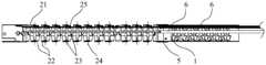
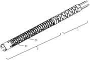
如图5和图7所示,除了上述自适应弯曲管,本申请还提供一种包括上述实施例公开的自适应弯曲管的内窥镜用弯曲管,该内窥镜用弯曲管还包括主动弯曲管2,主动弯曲管2的第一端用于与穿设于其内的牵引绳21相连,以通过牵引牵引绳21带动主动弯曲管2弯曲;主动弯曲管2的第二端与自适应弯曲管的第一端相连,自适应弯曲管的第二端用于与内窥镜的挠性管3相连。挠性管3主要用于实现内窥镜插入部与位于人体体腔外的操作部之间的连接。As shown in Figure 5 and Figure 7, in addition to the self-adaptive curved tube, the present application also provides a curved tube for endoscope including the self-adaptive curved tube disclosed in the above embodiment, and the curved tube for endoscope also includes an active The bending
也就是说,本实施例所提供的内窥镜用弯曲管既具有主动弯曲部分(即主动弯曲管2),又具有被动弯曲部分(即自适应弯曲管)。当将该内窥镜用弯曲管应用于内窥镜时,牵引绳21远离主动弯曲管2的一端与内窥镜的操作部200的角度控制旋钮连接,以通过操作角度控制旋钮,使其拉动牵引绳21,进而使牵引绳21带动主动弯曲管2弯曲,使主动弯曲管2顺利通过人体腔道,与此同时,在人体腔道的弯曲形状的限定下,对自适应弯曲管产生力的作用,使自适应弯曲管顺着人体腔道的形状自如弯曲,由上文所记载的内容可知,自适 应弯曲管的最大弯曲角度可控,因此,可根据人体腔道的形状,合理设计自适应弯曲管的最大弯曲角度,使得自适应弯曲管的最大弯曲角度能够满足人体腔道的形状需求;另外,自适应弯曲管的弯曲疲劳寿命长,可防止弯曲失效,因此,使得该内窥镜用弯曲管不仅可以应用于一次性内窥镜,还可以应用于重复性使用的内窥镜。That is to say, the curved tube for endoscope provided in this embodiment has both an active bending part (ie, the active bending tube 2 ) and a passive bending part (ie, the self-adaptive bending tube). When the endoscope bending tube is applied to an endoscope, the end of the
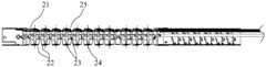
需要说明的是,本实施例对主动弯曲管2的具体结构及其弯曲原理等不做限定,作为一种可选的方案,如图5和图7所示,在上述实施例的基础之上,主动弯曲部包括若干个同轴设置的弯曲单元22,相邻两个弯曲单元22之间具有一定的间隔,且相邻弯曲单元22之间通过转轴(如铆钉23)转动连接,使得相邻两个弯曲单元22可绕转轴轴线24相对转动。在一些实施例中,相邻两个弯曲单元22通过关于弯曲单元22的轴线对称设置的两个转轴(如铆钉23)相连,且一个弯曲单元22分别与其两侧的弯曲单元22连接的转轴(如铆钉23)沿弯曲单元22的周向错开一定角度的设置。进一步地,在一些实施例中,一个弯曲单元22分别与其两侧的弯曲单元22连接的转轴(如铆钉23)垂直设置(如图9所示),这样,通过操作牵引绳21,可以使主动弯曲管2分别绕着相互垂直的两个转轴轴线24来回转动,例如,当一个弯曲单元22分别与其两侧的弯曲单元22连接的转轴(如铆钉23)分别为竖直方向和水平方向时,可使主动弯曲管2实现上下左右四个方向的旋转,通过运动的复合,可实现主动弯曲管2沿360°任意方向的弯曲。It should be noted that this embodiment does not limit the specific structure and bending principle of the
可以理解的是,为了便于控制主动弯曲管2朝各个方向的旋转,在一些实施例中,牵引绳21的数量与弯曲单元22的周向上不同角度的转轴(如铆钉23)的数量相同。例如,如图9所示,当一个弯曲单元22分别与四个转轴(如铆钉23)连接,四个转轴(如铆钉23)两两一对的分别关于弯曲单元22的轴线对称设置,不同对的转轴(如铆钉23)垂直设置,且不同弯曲单元22的四个转轴(如铆钉23)分别一一对准,分别位于四条直线上,则牵引绳21的数量为四个,四个牵引绳21均穿设于主动弯曲管2内,如图6和图8所示,弯曲单元22上对应每一个转轴(如铆钉23)的位置分别设有导向环25,牵引绳21从导向环25内穿过,当操作者通过操作部200的角度控制旋钮拉动对应的牵引绳21时,牵引绳21的牵引力通过导向环25传递至弯曲单元22,进而使弯曲单元22绕着对应的转轴(如铆钉23)的轴线旋转,从而使主动弯曲管2 朝某一方向(比如上方或下方或左方或右方等)弯曲。It can be understood that, in order to control the rotation of the
另外,在上述实施例中,对自适应弯曲管与主动弯曲管2之间的具体连接方式不做限定,只要能够实现两者的连接即可,考虑到两者连接的方便性,作为一种可选的方案,在上述实施例的基础之上,自适应弯曲管通过转接圈5与主动弯曲管2相连。如图6和8所示,在一些实施例中,转接圈5包括用于与主动弯曲管2套接的第一套接部和用于与自适应弯曲管套接的第二套接部,主动弯曲管2与第一套接部之间以及自适应弯曲管与第二套接部之间分别通过紧固件相连或通过铆接固定或通过焊接等其它方式固定。In addition, in the above-mentioned embodiment, the specific connection mode between the adaptive bending tube and the
可以理解的是,牵引绳21从内窥镜的挠性管3穿入,依次经过自适应弯曲管和主动弯曲管2至主动弯曲管2的第一端,并与主动弯曲管2的第一端连接,因此,当牵引绳21受拉控制主动弯曲管2弯曲时,牵引绳21的刚性会增强,这将影响自适应弯曲管和挠性管3的性能,为了减小牵引绳21的刚性对自适应弯曲管和挠性管3的影响,在一些实施例中,如图6和8所示,在自适应弯曲管和挠性管3内穿设有弹性管6,弹性管6用于供牵引绳21穿过,考虑到弹性管6固定的方便性,在一些实施例中,弹性管6的一端与转接圈5相连,弹性管6的另一端与挠性管3远离自适应弯曲管的一端或内窥镜的操作部相连,以此保证主动弯曲管2弯曲时自适应弯曲管及挠性管3的性能。It can be understood that the
需要说明的是,弹性管6的数量有多个,其与牵引绳21的数量相同,且两者一一对应设置,也即,每个弹性管6内穿设有一个牵引绳21。例如,当牵引绳21的数量为四个时,弹性管6的数量也为四个,每个牵引绳21的外周部都套设有弹性管6,此时,通过四个牵引绳21控制四个弯曲方向,以实现多自由度的牵引。It should be noted that there are multiple
除了上述自适应弯曲管和内窥镜用弯曲管,本申请还提供一种包括上述实施例公开的内窥镜用弯曲管的插入部,以及,包括该插入部的内窥镜。该内窥镜的其它各部分的结构请参考现有技术。In addition to the self-adaptive curved tube and the curved tube for endoscope, the present application also provides an insertion part including the curved tube for endoscope disclosed in the above embodiments, and an endoscope including the insertion part. Please refer to the prior art for the structures of other parts of the endoscope.
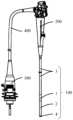
如图10所示,内窥镜包括插入部100、操作部200、连接器300以及连接管道400,其中,插入部100用于进入人体进行检查,其包括前端部4、内窥镜用弯曲管和挠性管3,前端部4与内窥镜用弯曲管的主动弯曲管2的第一端相连,挠性管3与内窥镜用弯曲管的自适应弯曲管的第二端相连;前端部4设有摄像单元、器械通道以及水气通道等结构,用于直观观察人体目标区域并 便于利用器械进行辅助治疗等。挠性管3远离自适应弯曲管的一端与操作部200相连,操作部200上设有用于控制插入部100的主动弯曲管2弯曲的角度控制旋钮以及其它各种功能按钮,使得操作者根据需求实现各对应功能。操作部200通过连接管道400与连接器300相连,连接器300用于与内窥镜的处理器以及光源等外部设备连接,连接器300通过连接管道400、操作部200与插入部100实现信号、照明光或其他功能的传输及连接。As shown in Figure 10, the endoscope includes an
由于该插入部和内窥镜包括上述内窥镜用弯曲管,而内窥镜用弯曲管包括上述实施例公开的自适应弯曲管,自适应弯曲管的最大弯曲角度可控,且其弯曲不易失效,因此,使得该插入部具有较好的腔道适应性,进而,该内窥镜具有较佳的插入性能。Since the insertion part and the endoscope include the above-mentioned curved tube for endoscope, and the curved tube for endoscope includes the self-adaptive curved tube disclosed in the above embodiment, the maximum bending angle of the self-adaptive curved tube is controllable, and its bending is not easy. Failure, therefore, makes the insertion part have better lumen adaptability, and further, the endoscope has better insertion performance.
如图11和12所示,为内窥镜的插入部100插入人体腔道内的示意图。As shown in FIGS. 11 and 12 , they are schematic views of inserting the
还需要说明的是,在本说明书中,诸如第一和第二等之类的关系术语仅仅用来将一个实体或者操作与另一个实体或操作区分开来,而不一定要求或者暗示这些实体或操作之间存在任何这种实际的关系或者顺序。It should also be noted that in this specification, relative terms such as first and second are only used to distinguish one entity or operation from another entity or operation, and do not necessarily require or imply that these entities or operations There is no such actual relationship or order between the operations.
本说明书中各个实施例采用递进方式描述,每个实施例重点说明的都是与其它实施例的不同之处,各个实施例之间相同相似部分互相参见即可。Each embodiment in this specification is described in a progressive manner, each embodiment focuses on the difference from other embodiments, and the same and similar parts of each embodiment can be referred to each other.
以上对本申请所提供的自适应弯曲管、内窥镜用弯曲管及内窥镜进行了详细介绍。本文中应用了具体个例对本申请的原理及实施方式进行了阐述,以上实施例的说明只是用于帮助理解本申请的方法及其核心思想。应当指出,对于本技术领域的普通技术人员来说,在不脱离本申请原理的前提下,还可以对本申请进行若干改进和修饰,这些改进和修饰也落入本申请权利要求的保护范围内。The self-adaptive bending tube, the bending tube for endoscope and the endoscope provided by the present application have been introduced in detail above. In this paper, specific examples are used to illustrate the principles and implementation methods of the present application, and the descriptions of the above embodiments are only used to help understand the methods and core ideas of the present application. It should be pointed out that those skilled in the art can make some improvements and modifications to the application without departing from the principles of the application, and these improvements and modifications also fall within the protection scope of the claims of the application.
Claims (19)
Translated fromChineseApplications Claiming Priority (2)
| Application Number | Priority Date | Filing Date | Title |
|---|---|---|---|
| CN202110969088.8 | 2021-08-23 | ||
| CN202110969088.8ACN115104996B (en) | 2021-08-23 | 2021-08-23 | Adaptive bending tube, bending tube for endoscope, insertion part and endoscope |
Publications (1)
| Publication Number | Publication Date |
|---|---|
| WO2023025119A1true WO2023025119A1 (en) | 2023-03-02 |
Family
ID=83324916
Family Applications (1)
| Application Number | Title | Priority Date | Filing Date |
|---|---|---|---|
| PCT/CN2022/114094CeasedWO2023025119A1 (en) | 2021-08-23 | 2022-08-23 | Self-adaptive bent tube, bent tube for endoscope, insertion portion and endoscope |
Country Status (2)
| Country | Link |
|---|---|
| CN (1) | CN115104996B (en) |
| WO (1) | WO2023025119A1 (en) |
Cited By (3)
| Publication number | Priority date | Publication date | Assignee | Title |
|---|---|---|---|---|
| CN116688339A (en)* | 2023-07-31 | 2023-09-05 | 科弛医疗科技(北京)有限公司 | Medicine sprayer and surgical robot |
| CN118633893A (en)* | 2024-08-14 | 2024-09-13 | 湖南省华芯医疗器械有限公司 | Active bending section, endoscope and bending radius control method |
| CN118664348A (en)* | 2024-08-23 | 2024-09-20 | 湖南省华芯医疗器械有限公司 | Processing method of active bending section and active bending section |
Families Citing this family (4)
| Publication number | Priority date | Publication date | Assignee | Title |
|---|---|---|---|---|
| CN116211222B (en)* | 2023-01-31 | 2025-01-28 | 湖南省华芯医疗器械有限公司 | Endoscope guiding device and endoscope |
| CN116616680B (en)* | 2023-05-29 | 2025-07-04 | 湖南省华芯医疗器械有限公司 | Active bending section, insertion portion and endoscope |
| CN117158869A (en)* | 2023-10-17 | 2023-12-05 | 湖南省华芯医疗器械有限公司 | Endoscope and active bending section thereof |
| CN118452796B (en)* | 2024-07-11 | 2024-09-27 | 湖南省华芯医疗器械有限公司 | Snake bone assembly, insertion part and endoscope |
Citations (14)
| Publication number | Priority date | Publication date | Assignee | Title |
|---|---|---|---|---|
| JPH08160313A (en)* | 1994-12-02 | 1996-06-21 | Olympus Optical Co Ltd | Curved pipe of endoscope |
| US5772578A (en)* | 1995-09-14 | 1998-06-30 | Richard Wolf Gmbh | Endoscopic instrument |
| US5807241A (en)* | 1995-09-22 | 1998-09-15 | Richard Wolf Gmbh | Bendable tube and method for its manufacture |
| JP2007236754A (en)* | 2006-03-10 | 2007-09-20 | Olympus Corp | Bending section of endoscope, endoscope, and method for manufacturing bending section of endoscope |
| CN102858227A (en)* | 2010-04-26 | 2013-01-02 | 奥林巴斯医疗株式会社 | Endoscope |
| CN107518860A (en)* | 2017-06-29 | 2017-12-29 | 杭州无创光电有限公司 | Endoscope snake bone structure and endoscope |
| CN108095672A (en)* | 2018-01-23 | 2018-06-01 | 深圳市先赞科技有限公司 | Without using the endoscope snake bone component of rivet interlacement |
| CN109497913A (en)* | 2018-12-25 | 2019-03-22 | 深圳市先赞科技有限公司 | Curvature section of endoscope and endoscope |
| US20190151615A1 (en)* | 2016-07-20 | 2019-05-23 | Terumo Kabushiki Kaisha | Medical elongated body |
| CN212788442U (en)* | 2020-04-29 | 2021-03-26 | 上海安清医疗器械有限公司 | Passive bending tube, multi-section bending tube and endoscope |
| US20210127947A1 (en)* | 2017-10-20 | 2021-05-06 | Anqing Medical Co., Ltd | Multi-section bending tube having graduated rigidity, insertion tube for endoscope using the bending tube, and endoscope |
| CN112969398A (en)* | 2018-10-31 | 2021-06-15 | Hoya株式会社 | Method for producing an insertion tube of an endoscope and endoscope having an insertion tube |
| CN215687667U (en)* | 2021-08-05 | 2022-02-01 | 深圳开立生物医疗科技股份有限公司 | Snake bone and endoscope |
| CN216256996U (en)* | 2021-08-23 | 2022-04-12 | 深圳开立生物医疗科技股份有限公司 | Self-adaptive bending tube, bending tube for endoscope and endoscope |
Family Cites Families (3)
| Publication number | Priority date | Publication date | Assignee | Title |
|---|---|---|---|---|
| CN109288486B (en)* | 2018-10-22 | 2021-03-26 | 上海安清医疗器械有限公司 | Multi-section bending tube device of endoscope and endoscope |
| WO2020135362A1 (en)* | 2018-12-25 | 2020-07-02 | 深圳市先赞科技有限公司 | Bending part of endoscope, and endoscope |
| CN109497915B (en)* | 2018-12-25 | 2024-03-22 | 深圳市先赞科技有限公司 | Bending part of endoscope and endoscope |
- 2021
- 2021-08-23CNCN202110969088.8Apatent/CN115104996B/enactiveActive
- 2022
- 2022-08-23WOPCT/CN2022/114094patent/WO2023025119A1/ennot_activeCeased
Patent Citations (14)
| Publication number | Priority date | Publication date | Assignee | Title |
|---|---|---|---|---|
| JPH08160313A (en)* | 1994-12-02 | 1996-06-21 | Olympus Optical Co Ltd | Curved pipe of endoscope |
| US5772578A (en)* | 1995-09-14 | 1998-06-30 | Richard Wolf Gmbh | Endoscopic instrument |
| US5807241A (en)* | 1995-09-22 | 1998-09-15 | Richard Wolf Gmbh | Bendable tube and method for its manufacture |
| JP2007236754A (en)* | 2006-03-10 | 2007-09-20 | Olympus Corp | Bending section of endoscope, endoscope, and method for manufacturing bending section of endoscope |
| CN102858227A (en)* | 2010-04-26 | 2013-01-02 | 奥林巴斯医疗株式会社 | Endoscope |
| US20190151615A1 (en)* | 2016-07-20 | 2019-05-23 | Terumo Kabushiki Kaisha | Medical elongated body |
| CN107518860A (en)* | 2017-06-29 | 2017-12-29 | 杭州无创光电有限公司 | Endoscope snake bone structure and endoscope |
| US20210127947A1 (en)* | 2017-10-20 | 2021-05-06 | Anqing Medical Co., Ltd | Multi-section bending tube having graduated rigidity, insertion tube for endoscope using the bending tube, and endoscope |
| CN108095672A (en)* | 2018-01-23 | 2018-06-01 | 深圳市先赞科技有限公司 | Without using the endoscope snake bone component of rivet interlacement |
| CN112969398A (en)* | 2018-10-31 | 2021-06-15 | Hoya株式会社 | Method for producing an insertion tube of an endoscope and endoscope having an insertion tube |
| CN109497913A (en)* | 2018-12-25 | 2019-03-22 | 深圳市先赞科技有限公司 | Curvature section of endoscope and endoscope |
| CN212788442U (en)* | 2020-04-29 | 2021-03-26 | 上海安清医疗器械有限公司 | Passive bending tube, multi-section bending tube and endoscope |
| CN215687667U (en)* | 2021-08-05 | 2022-02-01 | 深圳开立生物医疗科技股份有限公司 | Snake bone and endoscope |
| CN216256996U (en)* | 2021-08-23 | 2022-04-12 | 深圳开立生物医疗科技股份有限公司 | Self-adaptive bending tube, bending tube for endoscope and endoscope |
Cited By (4)
| Publication number | Priority date | Publication date | Assignee | Title |
|---|---|---|---|---|
| CN116688339A (en)* | 2023-07-31 | 2023-09-05 | 科弛医疗科技(北京)有限公司 | Medicine sprayer and surgical robot |
| CN116688339B (en)* | 2023-07-31 | 2024-03-22 | 科弛医疗科技(北京)有限公司 | Medicine sprayer and surgical robot |
| CN118633893A (en)* | 2024-08-14 | 2024-09-13 | 湖南省华芯医疗器械有限公司 | Active bending section, endoscope and bending radius control method |
| CN118664348A (en)* | 2024-08-23 | 2024-09-20 | 湖南省华芯医疗器械有限公司 | Processing method of active bending section and active bending section |
Also Published As
| Publication number | Publication date |
|---|---|
| CN115104996A (en) | 2022-09-27 |
| CN115104996B (en) | 2025-09-12 |
Similar Documents
| Publication | Publication Date | Title |
|---|---|---|
| WO2023025119A1 (en) | Self-adaptive bent tube, bent tube for endoscope, insertion portion and endoscope | |
| US11596296B2 (en) | Endoscope | |
| WO2023174093A1 (en) | Handle bending control and locking mechanism, endoscope handle and endoscope system | |
| KR100922916B1 (en) | Flexible tube for endoscope and endoscope device | |
| US20210113064A1 (en) | Bending operation mechanism of endoscope, and endoscope | |
| WO2020135361A1 (en) | Endoscope | |
| CN117860179B (en) | Multi-forceps endoscope and surgical system | |
| CN218105858U (en) | Bending tube, insertion part and endoscope | |
| EP3135182A1 (en) | Endoscope bending section and endoscope | |
| US9848759B2 (en) | Coil structure used in endoscope and endoscope and treatment instrument including coil structure | |
| WO2025184970A1 (en) | Adjustably bending catheter assembly and medical instrument | |
| CN216256996U (en) | Self-adaptive bending tube, bending tube for endoscope and endoscope | |
| CN116784773A (en) | Handle bending control locking mechanism, endoscope handle and endoscope system | |
| CN116616680B (en) | Active bending section, insertion portion and endoscope | |
| CN116616682B (en) | Active bending section, insertion portion and endoscope | |
| JP2013150700A (en) | Endoscope | |
| CN112515613A (en) | Endoscope device | |
| CN218922519U (en) | Snake bone segment, insertion part and endoscope | |
| CN117243547A (en) | Snake bone structure and endoscope | |
| CN116636795A (en) | Active bending section, insertion section and endoscope | |
| CN111281627A (en) | Stent implanter driving mechanism and medical stent implanter | |
| CN118717005A (en) | Endoscopic snake bone and endoscope | |
| CN214387404U (en) | Endoscope device | |
| CN219846512U (en) | Active bending section, insertion part and endoscope | |
| JP3273070B2 (en) | Endoscope |
Legal Events
| Date | Code | Title | Description |
|---|---|---|---|
| 121 | Ep: the epo has been informed by wipo that ep was designated in this application | Ref document number:22860465 Country of ref document:EP Kind code of ref document:A1 | |
| NENP | Non-entry into the national phase | Ref country code:DE | |
| 122 | Ep: pct application non-entry in european phase | Ref document number:22860465 Country of ref document:EP Kind code of ref document:A1 |