WO2023021596A1 - Noise control method and noise control device - Google Patents
Noise control method and noise control deviceDownload PDFInfo
- Publication number
- WO2023021596A1 WO2023021596A1PCT/JP2021/030133JP2021030133WWO2023021596A1WO 2023021596 A1WO2023021596 A1WO 2023021596A1JP 2021030133 WJP2021030133 WJP 2021030133WWO 2023021596 A1WO2023021596 A1WO 2023021596A1
- Authority
- WO
- WIPO (PCT)
- Prior art keywords
- noise
- engine
- controller
- performance
- reducing
- Prior art date
- Legal status (The legal status is an assumption and is not a legal conclusion. Google has not performed a legal analysis and makes no representation as to the accuracy of the status listed.)
- Ceased
Links
Images


Classifications
- G—PHYSICS
- G10—MUSICAL INSTRUMENTS; ACOUSTICS
- G10K—SOUND-PRODUCING DEVICES; METHODS OR DEVICES FOR PROTECTING AGAINST, OR FOR DAMPING, NOISE OR OTHER ACOUSTIC WAVES IN GENERAL; ACOUSTICS NOT OTHERWISE PROVIDED FOR
- G10K11/00—Methods or devices for transmitting, conducting or directing sound in general; Methods or devices for protecting against, or for damping, noise or other acoustic waves in general
- G10K11/16—Methods or devices for protecting against, or for damping, noise or other acoustic waves in general
- G10K11/175—Methods or devices for protecting against, or for damping, noise or other acoustic waves in general using interference effects; Masking sound
- G10K11/178—Methods or devices for protecting against, or for damping, noise or other acoustic waves in general using interference effects; Masking sound by electro-acoustically regenerating the original acoustic waves in anti-phase
- G10K11/1783—Methods or devices for protecting against, or for damping, noise or other acoustic waves in general using interference effects; Masking sound by electro-acoustically regenerating the original acoustic waves in anti-phase handling or detecting of non-standard events or conditions, e.g. changing operating modes under specific operating conditions
- B—PERFORMING OPERATIONS; TRANSPORTING
- B60—VEHICLES IN GENERAL
- B60R—VEHICLES, VEHICLE FITTINGS, OR VEHICLE PARTS, NOT OTHERWISE PROVIDED FOR
- B60R11/00—Arrangements for holding or mounting articles, not otherwise provided for
- B60R11/02—Arrangements for holding or mounting articles, not otherwise provided for for radio sets, television sets, telephones, or the like; Arrangement of controls thereof
- G—PHYSICS
- G10—MUSICAL INSTRUMENTS; ACOUSTICS
- G10K—SOUND-PRODUCING DEVICES; METHODS OR DEVICES FOR PROTECTING AGAINST, OR FOR DAMPING, NOISE OR OTHER ACOUSTIC WAVES IN GENERAL; ACOUSTICS NOT OTHERWISE PROVIDED FOR
- G10K11/00—Methods or devices for transmitting, conducting or directing sound in general; Methods or devices for protecting against, or for damping, noise or other acoustic waves in general
- G10K11/16—Methods or devices for protecting against, or for damping, noise or other acoustic waves in general
- G10K11/175—Methods or devices for protecting against, or for damping, noise or other acoustic waves in general using interference effects; Masking sound
- G10K11/178—Methods or devices for protecting against, or for damping, noise or other acoustic waves in general using interference effects; Masking sound by electro-acoustically regenerating the original acoustic waves in anti-phase
- G10K11/1781—Methods or devices for protecting against, or for damping, noise or other acoustic waves in general using interference effects; Masking sound by electro-acoustically regenerating the original acoustic waves in anti-phase characterised by the analysis of input or output signals, e.g. frequency range, modes, transfer functions
- G10K11/17821—Methods or devices for protecting against, or for damping, noise or other acoustic waves in general using interference effects; Masking sound by electro-acoustically regenerating the original acoustic waves in anti-phase characterised by the analysis of input or output signals, e.g. frequency range, modes, transfer functions characterised by the analysis of the input signals only
- G10K11/17823—Reference signals, e.g. ambient acoustic environment
- G—PHYSICS
- G10—MUSICAL INSTRUMENTS; ACOUSTICS
- G10K—SOUND-PRODUCING DEVICES; METHODS OR DEVICES FOR PROTECTING AGAINST, OR FOR DAMPING, NOISE OR OTHER ACOUSTIC WAVES IN GENERAL; ACOUSTICS NOT OTHERWISE PROVIDED FOR
- G10K11/00—Methods or devices for transmitting, conducting or directing sound in general; Methods or devices for protecting against, or for damping, noise or other acoustic waves in general
- G10K11/16—Methods or devices for protecting against, or for damping, noise or other acoustic waves in general
- G10K11/175—Methods or devices for protecting against, or for damping, noise or other acoustic waves in general using interference effects; Masking sound
- G10K11/178—Methods or devices for protecting against, or for damping, noise or other acoustic waves in general using interference effects; Masking sound by electro-acoustically regenerating the original acoustic waves in anti-phase
- G10K11/1787—General system configurations
- G10K11/17873—General system configurations using a reference signal without an error signal, e.g. pure feedforward
- G—PHYSICS
- G10—MUSICAL INSTRUMENTS; ACOUSTICS
- G10K—SOUND-PRODUCING DEVICES; METHODS OR DEVICES FOR PROTECTING AGAINST, OR FOR DAMPING, NOISE OR OTHER ACOUSTIC WAVES IN GENERAL; ACOUSTICS NOT OTHERWISE PROVIDED FOR
- G10K11/00—Methods or devices for transmitting, conducting or directing sound in general; Methods or devices for protecting against, or for damping, noise or other acoustic waves in general
- G10K11/16—Methods or devices for protecting against, or for damping, noise or other acoustic waves in general
- G10K11/175—Methods or devices for protecting against, or for damping, noise or other acoustic waves in general using interference effects; Masking sound
- G10K11/178—Methods or devices for protecting against, or for damping, noise or other acoustic waves in general using interference effects; Masking sound by electro-acoustically regenerating the original acoustic waves in anti-phase
- G10K11/1787—General system configurations
- G10K11/17879—General system configurations using both a reference signal and an error signal
- G10K11/17883—General system configurations using both a reference signal and an error signal the reference signal being derived from a machine operating condition, e.g. engine RPM or vehicle speed
- G—PHYSICS
- G10—MUSICAL INSTRUMENTS; ACOUSTICS
- G10K—SOUND-PRODUCING DEVICES; METHODS OR DEVICES FOR PROTECTING AGAINST, OR FOR DAMPING, NOISE OR OTHER ACOUSTIC WAVES IN GENERAL; ACOUSTICS NOT OTHERWISE PROVIDED FOR
- G10K2210/00—Details of active noise control [ANC] covered by G10K11/178 but not provided for in any of its subgroups
- G10K2210/10—Applications
- G10K2210/128—Vehicles
- G10K2210/1282—Automobiles
Definitions
- the present inventionrelates to a noise control method and a noise control device.
- Patent Document 1an invention for reducing noise (mainly road noise) inside a vehicle has been known (Patent Document 1).
- the invention described in Patent Document 1stops the adaptive operation of the controller when it is determined that the change state of the transfer function from the noise source to the evaluation point exceeds a predetermined state.
- the present inventionhas been made in view of the above problems, and its object is to provide a noise control method and a noise control device that make it difficult for passengers to notice engine noise.
- a noise control methodreduces performance for reducing noise caused by vibrations input from the road surface according to the state of the engine.
- FIG. 1is a configuration example of a noise control device 1 according to an embodiment of the present invention.
- FIG. 2is a flowchart for explaining an operation example of the noise control device 1.
- FIG. FIG. 3is a graph showing the relationship between engine speed and noise level.
- FIG. 4is a flowchart for explaining an operation example of the noise control device 1.
- FIG. FIG. 5is a diagram for explaining an example of timing for reducing road noise reduction performance.
- FIG. 6is a diagram for explaining an example of timing for reducing road noise reduction performance.
- FIG. 7is a graph showing the relationship between frequency and noise level.
- FIG. 8is a flow chart for explaining an operation example of the noise control device 1.
- FIG. FIG. 9is a flowchart for explaining an operation example of the noise control device 1.
- FIG. 10is a diagram illustrating an example of the timing of outputting sound.
- FIG. 11is a flowchart for explaining an operation example of the noise control device 1.
- FIG. 12A and 12Bare diagrams for explaining another operation example of the noise control device 1.
- FIG. 13A and 13Bare diagrams for explaining another operation example of the noise control device 1.
- FIG. 14is a graph showing the relationship between frequency and noise level.
- the noise control device 1is installed inside the vehicle. As shown in FIG. 1, the noise control device 1 includes a wheel speed sensor 10, an engine 11, an acceleration sensor 12, a microphone 13, a controller 20, and a speaker 30.
- the wheel speed sensor 10detects the rotational speed of each tire and outputs a signal indicating the detected rotational speed to the controller 20 .
- the engine mounted on the vehicleis used to drive the tires.
- the engine 11 according to this embodimentwill be described as being used only for power generation. That is, the engine 11 according to this embodiment is not connected to tires, but is connected to a generator (not shown).
- the engine 11turns a generator, which produces electricity. However, it is not limited to this.
- the engine 11may be connected to the tires.
- connectionused herein may mean “indirect connection” or “direct connection”.
- the engine 11outputs a signal indicating its own state to the controller 20 .
- the state of the engine 11includes, for example, the number of revolutions of the engine 11, a state in which the engine 11 will start in the future, and a state in which the engine 11 will stop in the future.
- the signals that the engine 11 outputs to the controller 20include a signal indicating the rotation speed of the engine 11, a signal indicating that the engine 11 will start in the future, and a signal indicating that the engine 11 will stop in the future.
- a plurality of acceleration sensors 12are installed. Although the installation location of the acceleration sensor 12 is not particularly limited, it is, for example, a tire or its vicinity, or the engine 11 or its vicinity.
- the acceleration sensor 12detects vibrations input from the road surface when the vehicle travels.
- the acceleration sensor 12outputs the detected vibration data to the controller 20 .
- An acceleration sensor 12 installed on or near the engine 11detects the acceleration (vibration) of the engine 11 .
- the vibration of the engine 11increases as the output and rotation speed of the engine 11 increase.
- the noise of the engine 11increases as the vibration of the engine 11 increases.
- the acceleration sensor 12outputs the detected acceleration of the engine 11 to the controller 20 .
- a plurality of microphones 13are installed in the vehicle.
- the installation location of the microphone 13is not particularly limited, but is, for example, the ceiling of the vehicle or the seat (headrest).
- a sound input to the microphone 13is converted into an electric signal and output to the controller 20 as sound data.
- a microphone 13 installed on the ceiling, seat, etc. of the vehicledetects the noise of the engine 11 .
- the controller 20is a general-purpose microcomputer equipped with a CPU, memory, and input/output unit.
- a computer program for functioning as the noise control device 1is installed in the microcomputer.
- the microcomputerfunctions as a plurality of information processing circuits included in the noise control device 1.
- FIG.Here, an example of realizing a plurality of information processing circuits provided in the noise control device 1 by software is shown, but of course, dedicated hardware for executing each information processing described below is prepared to configure the information processing circuit. It is also possible to Also, a plurality of information processing circuits may be configured by individual hardware.
- the controller 20includes an engine state detection section 21, an environment detection section 22, and a noise control section 23 as an example of a plurality of information processing circuits.
- the engine state detection unit 21detects the state of the engine 11 using data acquired from the wheel speed sensor 10, the engine 11, the acceleration sensor 12, and the microphone 13. An example of the state of the engine 11 is described above.
- the engine state detector 21outputs a signal corresponding to the state of the engine 11 to the noise controller 23 .
- the environment detection unit 22uses data acquired from the wheel speed sensor 10, the engine 11, the acceleration sensor 12, and the microphone 13 to detect the environment of the vehicle.
- the "vehicle environment” in this embodimentwill be described later.
- the environment detector 22outputs a signal corresponding to the environment of the vehicle to the noise controller 23 .
- the noise control unit 23analyzes the vibration data acquired from the acceleration sensor 12 and the sound data acquired from the microphone 13 .
- the noise control unit 23generates an anti-phase sound signal with respect to the analyzed vibration data and sound data.
- the noise control unit 23outputs the generated sound signal from the speaker 30 .
- the noiseis canceled by the anti-phase waves, so that the noise is reduced.
- Such a noise control methodis called “active noise control” and is a well-known technology.
- active noise controlmay be simply abbreviated as "ANC”.
- the noise control section 23changes the performance of ANC based on the signal acquired from the engine state detection section 21 or the environment detection section 22 .
- step S101the engine state detector 21 determines whether or not the state of the engine 11 has changed.
- the engine state detection unit 21outputs a signal regarding the determination to the noise control unit 23 (YES in step S101).
- the engine state detection unit 21outputs a signal regarding the determination to the noise control unit 23 (NO in step S101).
- step S103the noise control unit 23 performs normal noise control.
- An example of "normal noise control”is ANC itself.
- step S105the noise control unit 23 reduces the road noise reduction performance.
- “Road noise”is noise caused by vibration input from the road surface.
- road noiseis noise generated by friction and collision between the road surface and tires when the vehicle is running. ANC in this embodiment reduces this "road noise”.
- the acceleration sensor 12is mainly used to detect vibrations related to "road noise". “Reducing the road noise reduction performance” means reducing the performance for reducing “road noise” (weakening the effect of ANC). As a specific example, it means suppressing the anti-phase sound output from the speaker 30 . “Suppressing the sound of the opposite phase” means reducing the amplitude of the sound output from the speaker 30, or changing the amplitude and frequency of the sound output from the speaker 30 to be different from the state in which the effect of ANC is maximized. means to make By suppressing the sound output from the speaker 30 in this way, the effect of ANC is weakened and the noise inside the vehicle is increased.
- the start-up sound (noise) of the engine 11is mixed with the noise inside the vehicle, so that the passenger is less likely to notice the noise of the engine 11 .
- Another effectis that the passenger does not notice that the engine 11 has started.
- the engine 11 according to this embodimentis used only for power generation. Therefore, if the SOC (state of charge) of the battery is sufficient, whether or not the engine 11 is running has little effect on the occupant. Therefore, in order to provide the passenger with a comfortable driving environment, it is required to make it difficult for the passenger to notice the noise of the engine 11 . This embodiment realizes this.
- the noise control unit 23reduces the road noise reduction performance when the rotation speed of the engine 11 changes between 0 and a predetermined rotation speed. This will be described with reference to FIG.
- the horizontal axis in FIG. 3indicates the number of rotations of the engine 11, and the vertical axis indicates the noise level in the vehicle.
- the noise level inside the carincreases as it goes to the upper side of the graph.
- ANC OFFmeans that ANC is not functioning. If the ANC is not working, the noise inside the car is naturally loud.
- Maximum effect of ANCmeans that the effect of ANC is maximized. When the ANC effect is maximized, the noise inside the vehicle is low.
- Normal control in step S103may mean “maximum effect of ANC".
- the noise control unit 23reduces the road noise reduction performance according to the rotation speed. For example, the moment the engine 11 starts, the noise control unit 23 stops ANC. As the rotation speed of the engine 11 gradually increases, the noise control unit 23 reduces the degree of decrease. When the rotation speed of the engine 11 reaches the predetermined rotation speed A, the noise control unit 23 returns ANC to normal control. In other words, when the rotation speed of the engine 11 is lower than the predetermined rotation speed A, the noise control section 23 reduces the road noise reduction performance.
- the noise control unit 23may set B between 0 and A, and reduce the road noise reduction performance when the rotation speed of the engine 11 reaches a predetermined rotation speed B. Further, the noise control unit 23 sets C and D (C ⁇ D) between 0 and A, and when the rotation speed of the engine 11 is between a predetermined rotation speed C and a predetermined rotation speed D, the load Noise reduction performance may be reduced.
- step S101An example of “change in state of engine 11" in step S101 shown in FIG. "Change in state of engine 11" in step S101 may indicate that the engine 11 will change to a state in which it will start in the future. This point will be described with reference to FIGS.
- step S201 of FIG. 4the engine state detector 21 determines whether or not the engine 11 will start in the future. A signal output from the engine 11 is used for this determination.
- the engine state detection unit 21acquires a signal indicating that the engine 11 will start in the future
- the engine state detection unit 21determines that the engine 11 has changed to a state in which the engine 11 will start in the future (YES in step S201). After that, the process proceeds to step S205. If NO in step S201, the process proceeds to step S203.
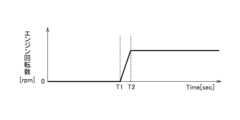
- a time T1 shown in FIG. 5indicates a time when the engine state detection unit 21 acquires a signal from the engine 11 indicating that the engine will be started in the future.
- Time T2indicates the time when the engine 11 is started.
- the noise control unit 23reduces the road noise reduction performance before the engine 11 starts.
- the starting sound of the engine 11is mixed with the noise inside the vehicle, so that the occupants are less likely to notice the noise of the engine 11.
- the noise control unit 23stops ANC immediately after time T1, but the present invention is not limited to this.
- the noise control unit 23may gradually decrease the road noise reduction performance from time T1 toward time T2, and stop ANC immediately before the engine 11 starts (time T2). This makes it possible to reduce the noise inside the vehicle between time T1 and time T2, as compared with FIG.
- An example of the timing at which the system mounted on the vehicle starts the engine 11is when the SOC of the battery becomes equal to or less than a predetermined value.
- “Change in state of engine 11" in step S101 shown in FIG. 2may include changes in data detected by acceleration sensor 12 or microphone 13.
- the acceleration sensor 12detects acceleration (vibration) of the engine 11 .
- a microphone 13detects the noise of the engine 11 .
- Engine state detector 21determines whether the data detected by acceleration sensor 12 or microphone 13 is greater than a predetermined value. If the data detected by the acceleration sensor 12 or the microphone 13 is larger than a predetermined value, the noise control section 23 may reduce the road noise reduction performance.
- the fact that the data detected by the acceleration sensor 12 or the microphone 13 is greater than a predetermined valuemeans that the engine 11 is running. Therefore, according to this method, it becomes difficult for the passenger to notice the noise of the engine 11 .
- the noise control unit 23may degrade road noise reduction performance.
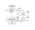
- step S301if the engine 11 has started (YES in step S301), the process proceeds to step S305. On the other hand, if the engine 11 has not started (NO in step S301), the process proceeds to step S303.
- step S305the environment detector 22 detects the environment of the vehicle. If the environment of the vehicle is the predetermined environment (YES in step S305), the process proceeds to step S307.
- step S305If the environment of the vehicle is not the predetermined environment (NO in step S305), the process proceeds to step S309.
- An example of the "vehicle environment"is the speed of the vehicle. If the speed is greater than the predetermined speed, the process of step S305 is YES. A speed higher than a predetermined speed means that the road noise is large. In this case, even if ANC is used, the noise inside the vehicle is large. Therefore, since the noise of the engine 11 is mixed with the noise inside the vehicle, there is no need to lower the road noise reduction performance. Therefore, the noise control unit 23 does not degrade the performance for reducing noise when the speed is greater than the predetermined speed. "Do not degrade performance for noise reduction” means that normal ANC is performed. On the other hand, if the speed is less than or equal to the predetermined speed (NO in step S305), the noise control unit 23 reduces the road noise reduction performance (step S309).
- Vehicle environmentmay include data detected by the acceleration sensor 12 or the microphone 13 immediately before the engine 11 starts. If the data detected by the acceleration sensor 12 or the microphone 13 immediately before the engine 11 is started is greater than the predetermined value, the processing in step S305 is YES.
- the fact that the data detected by the acceleration sensor 12 or the microphone 13 is larger than a predetermined value immediately before the engine 11 startsmeans that the road noise is large. Therefore, since the noise of the engine 11 is mixed with the noise inside the vehicle, there is no need to lower the road noise reduction performance. Accordingly, the noise control unit 23 does not degrade the noise reduction performance when the data detected by the acceleration sensor 12 or the microphone 13 immediately before the engine 11 is started is greater than a predetermined value. On the other hand, if the data detected by the acceleration sensor 12 or the microphone 13 immediately before the engine 11 starts is equal to or less than the predetermined value (NO in step S305), the noise control unit 23 reduces the road noise reduction performance (step S309). ).
- step S ⁇ b>407the noise control unit 23 outputs sound from the speaker 30 .
- the processing of step S405reduces the road noise reduction performance.
- the road noise itselfis small, even if the road noise reduction performance is lowered, the effect is limited (the road noise does not increase so much). In this case, the starting sound of the engine 11 is less likely to be mixed with the noise inside the vehicle. In other words, the occupant can easily notice the noise of the engine 11 .
- the noise control unit 23outputs sound from the speaker 30 in step S407. This makes it possible to drown out the start-up sound of the engine 11 .
- the noise control unit 23may output a sound louder than the road noise from the speaker 30 .
- the noise control unit 23uses a sound having an amplitude larger than that of the road noise, so that the speaker 30 can output a sound larger than the road noise.
- the processing of step S407may be expressed as outputting a sound louder than the road noise from the speaker 30 . An example of timing for outputting sound will be described with reference to FIG.
- Time T1 in FIG. 10indicates the timing when the deterioration of the road noise reduction performance starts.
- Time T2indicates the timing when ANC is stopped.
- the noise control unit 23gradually lowers the road noise reduction performance, and then stops the road noise reduction performance, and outputs sound from the speaker 30 at the same time.
- Reference numeral 50indicates that the noise level inside the vehicle has increased due to sound output. By outputting the sound in this way to increase the noise level inside the vehicle, it is possible to drown out the start-up sound of the engine 11 .
- “abnormal”means not normal.
- “Abnormality”is a concept that includes not only failures that prevent parts from performing their original functions, but also defects that do not lead to failures and signs of failures. Processing when an abnormality of the engine 11 is detected will be described with reference to FIG.
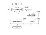
- a command to stop the ANCis output (YES in step S501).
- the noise control unit 23outputs sound from the speaker 30 .
- the sound output methodis the same as in FIG. Thereby, it is possible to notify the passenger that the engine 11 is abnormal.
- the noise control unit 23stops ANC. The process of FIG.
- the vehicleis equipped with many devices in addition to the engine 11 .
- the devicesinclude the above-described generators, motors, inverters, batteries, ANC systems, and the like.
- the noise control unit 23may notify the passenger (user in the vehicle) of the guidance to stop ANC.
- a method of providing stop guidancea method of displaying on a display (for example, a display of a navigation device) or a method of outputting sound from the speaker 30 may be used.
- An occupant who has received the stop guidancecan stop the ANC by pressing a virtual switch displayed on the display or pressing a physical switch installed in the vehicle.
- the noise control device 1includes an engine 11 mounted on the vehicle, and a controller 20 that detects the state of the engine 11 .
- the controller 20reduces performance for reducing noise caused by vibrations input from the road surface according to the state of the engine 11 .
- An example of "noise caused by vibration input from the road surface”is the above-mentioned “road noise”.
- the noise control device 1since the noise of the engine 11 is mixed with the noise inside the vehicle, it is difficult for the passengers to notice the noise of the engine 11. - ⁇
- the "noise of the engine 11"includes the "starting sound of the engine 11" and the "driving sound of the engine 11". Another effect is that the passenger does not notice that the engine 11 has started.
- the state of the engine 11includes the number of revolutions of the engine 11.
- the controller 20lowers the noise reduction performance when the rotation speed of the engine 11 reaches a predetermined rotation speed.
- An example of the "predetermined number of revolutions"is the "predetermined number of revolutions B" described above.
- the noise control device 1since the noise of the engine 11 is mixed with the noise inside the vehicle, it is difficult for the passengers to notice the noise of the engine 11. - ⁇
- the state of the engine 11includes the state in which the engine 11 will start in the future.
- the controller 20receives a signal indicating that the engine 11 will start in the future, it reduces performance to reduce noise.
- the starting sound of the engine 11is mixed with the noise inside the vehicle, so that the occupants are less likely to notice the noise of the engine 11. ⁇
- the controller 20When the controller 20 receives a signal indicating that the engine 11 will start in the future, the controller 20 gradually reduces the noise reduction performance before the engine 11 starts, and reduces the noise just before the engine 11 starts. stop performance for As a result, road noise can be reduced until just before the engine 11 starts. Since the starting sound of the engine 11 is mixed with the noise inside the vehicle, it is difficult for the passengers to notice the noise of the engine 11. ⁇
- the state of the engine 11includes vibration data detected by the acceleration sensor 12 or noise data detected by the microphone 13 .
- the controller 20reduces performance for reducing noise.
- the noise of the engine 11is mixed with the noise inside the vehicle, so that the occupants are less likely to notice the noise of the engine 11. - ⁇
- the controller 20reduces the noise reduction performance when the noise level of a predetermined frequency among the frequencies indicated by the vibration data or the noise data regarding the engine 11 is greater than a predetermined value. As a result, the noise of the engine 11 is mixed with the noise inside the vehicle, so that the occupants are less likely to notice the noise of the engine 11. - ⁇
- the controller 20detects the environment of the vehicle.
- the controller 20does not degrade performance to reduce noise in response to the sensed vehicle environment after the engine 11 has started. This is because when the noise inside the vehicle is loud, the noise of the engine 11 is mixed with the noise inside the vehicle.
- the vehicle's environmentincludes the vehicle's speed.
- the controller 20does not degrade performance to reduce noise if the speed is greater than a predetermined speed after the engine 11 has started.
- a speed higher than a predetermined speedmeans that the road noise is large. Since the noise of the engine 11 is mixed with the noise inside the vehicle, there is no need to lower the road noise reduction performance.
- the vehicle environmentincludes vibration data detected by the acceleration sensor 12 or noise data detected by the microphone 13 .
- the controller 20does not reduce noise reduction performance when the noise level indicated by the vibration data detected immediately before the engine 11 is started or the noise level indicated by the noise data is greater than a predetermined value. If these noise levels are greater than a predetermined value, it means that the road noise is large. Since the noise of the engine 11 is mixed with the noise inside the vehicle, there is no need to lower the road noise reduction performance.
- the "vibration data”here means “vibration data excluding the engine 11".
- noise datahere means “noise data excluding the engine 11".
- the controller 20reduces the performance for reducing noise according to the state of the engine 11, and then stops the performance for reducing noise and outputs sound from the speaker 30 at the same time. This makes it possible to drown out the noise of the engine 11 .
- a commandis output to the controller 20 to stop the noise reduction performance.
- the controller 20receives the command, the controller 20 stops the noise reduction performance after outputting the sound from the speaker 30, or instructs to stop the noise reduction performance after outputting the sound from the speaker 30. Notify crew. Thereby, the occupant can be notified that an abnormality has occurred in the device or the function of the device.
- Processing circuitryincludes programmed processing devices, such as processing devices that include electrical circuitry. Processing circuitry also includes devices such as application specific integrated circuits (ASICs) and circuit components arranged to perform the described functions.
- ASICsapplication specific integrated circuits
- Time T1 in FIG. 12indicates the timing when the engine 11 is started.
- Time T2indicates the timing when the engine 11 transitions to the steady state.
- a period between time T1 and time T2indicates a period from when the engine 11 is started until it transitions to a steady state.
- “Steady state”refers to a state in which the rotational speed of the engine 11 maintains a constant rotational speed.
- the "steady state”may be expressed as a state in which the change in the rotational speed of the engine 11 over time is smaller than a predetermined value.
- the controller 20reduces noise associated with the engine 11 when the engine 11 is running, and reduces noise caused by vibrations input from the road surface when the engine 11 is stopped. In other words, the controller 20 reduces noise caused by vibrations input from the road surface until time T1. The controller 20 reduces the noise associated with the engine 11 after time T2. As a result, the road noise is reduced until the engine 11 is started, and the noise associated with the engine 11 is reduced after the engine 11 is started.
- Time T1 in FIG. 13indicates the timing at which the engine 11 is started.
- Time T2is an arbitrary point indicating that the engine 11 continues to operate after transitioning to a steady state.
- the controller 20detects changes in the rotational speed of the engine 11 over time. When the time change of the rotation speed of the engine 11 is smaller than a predetermined value and the engine 11 is operating, the controller 20 does not reduce the noise caused by the vibrations input from the road surface, and only the noise related to the engine 11 is reduced. to reduce This makes it difficult for the occupant to notice the noise of the engine 11 .
- Reference numeral 60 shown in FIG. 14indicates that the engine 11 is running and ANC is stopped.
- Reference numeral 61indicates that the engine 11 is stopped and the ANC is stopped.
- Reference numeral 62indicates that ANC is operating using all sensors.
- Reference numeral 63indicates that only data detected by the acceleration sensor 12 and the microphone 13 installed in the engine 11 are used.
- the engine 11 is stoppedmay be defined as the rotation speed of the engine 11 being zero.
- “Noise related to the engine 11 ”may be defined as noise indicated by data detected by the acceleration sensor 12 or the microphone 13 installed in the engine 11 .
- “Noise caused by vibration input from the road surface”may be defined as noise indicated by data detected by the acceleration sensor 12 or the microphone 13 installed at a location other than the engine 11 .
- the controller 20may not reduce the noise related to the engine 11 and reduce the noise caused by the vibration input from the road surface. This efficiently reduces road noise.
- the controller 20selects the acceleration sensor installed in the engine 11 among the data detected by the plurality of acceleration sensors 12 when the time change of the rotation speed of the engine 11 is smaller than a predetermined value and the engine 11 is operating. Only data detected by 12 may be used to reduce noise associated with engine 11 . This makes it difficult for the occupant to notice the noise of the engine 11 .
- only data from the acceleration sensor 12may be used, only data from the microphone 13 may be used, or data from both the acceleration sensor 12 and the microphone 13 may be used.
- noise control device10 wheel speed sensor, 11 engine, 12 acceleration sensor, 13 microphone, 20 controller, 21 engine state detection unit, 22 environment detection unit, 23 noise control unit, 30 speaker
Landscapes
- Engineering & Computer Science (AREA)
- Physics & Mathematics (AREA)
- Acoustics & Sound (AREA)
- Multimedia (AREA)
- Mechanical Engineering (AREA)
- Fittings On The Vehicle Exterior For Carrying Loads, And Devices For Holding Or Mounting Articles (AREA)
- Soundproofing, Sound Blocking, And Sound Damping (AREA)
Abstract
Description
Translated fromJapanese本発明は、騒音制御方法及び騒音制御装置に関する。The present invention relates to a noise control method and a noise control device.
従来より、車両の室内の騒音(主にロードノイズ)を低減する発明が知られている(特許文献1)。特許文献1に記載された発明は、騒音源から評価点までの伝達関数の変化状態が所定状態を上回ると判断したとき、制御器の適応動作を停止する。Conventionally, an invention for reducing noise (mainly road noise) inside a vehicle has been known (Patent Document 1). The invention described in
特許文献1に記載された発明によれば、車内の騒音は低減される。しかしながら、車内の騒音が低減された状態でエンジンが起動した場合、エンジンの騒音が強調されてしまい、乗員が不快に感じるおそれがある。According to the invention described in
本発明は、上記問題に鑑みて成されたものであり、その目的は、エンジンの騒音を乗員に気づかせにくくする騒音制御方法及び騒音制御装置を提供することである。The present invention has been made in view of the above problems, and its object is to provide a noise control method and a noise control device that make it difficult for passengers to notice engine noise.
本発明の一態様に係る騒音制御方法は、エンジンの状態に応じて、路面から入力される振動に起因する騒音を低減するための性能を低下させる。A noise control method according to one aspect of the present invention reduces performance for reducing noise caused by vibrations input from the road surface according to the state of the engine.
本発明によれば、乗員はエンジンの騒音に気づきにくくなる。According to the present invention, it becomes difficult for passengers to notice the noise of the engine.
以下、本発明の実施形態について、図面を参照して説明する。図面の記載において同一部分には同一符号を付して説明を省略する。Hereinafter, embodiments of the present invention will be described with reference to the drawings. In the description of the drawings, the same parts are denoted by the same reference numerals, and the description thereof is omitted.
図1を参照して騒音制御装置1の構成例を説明する。騒音制御装置1は車内に設置される。図1に示すように、騒音制御装置1は、車輪速センサ10と、エンジン11と、加速度センサ12と、マイク13と、コントローラ20と、スピーカ30とを備える。A configuration example of the
車輪速センサ10は、各タイヤの回転速度を検出し、検出した回転速度を示す信号をコントローラ20に出力する。The
一般に車両に搭載されるエンジンは、タイヤを駆動させるために用いられる。しかし、本実施形態に係るエンジン11は、発電のみに用いられるものとして説明する。すなわち、本実施形態に係るエンジン11は、タイヤに接続されておらず、発電機(不図示)に接続されている。エンジン11は発電機を回し、これにより電気が生成される。ただし、これに限定されない。通常のように、エンジン11はタイヤに接続されてもよい。ここでいう「接続」とは、「間接的に接続」という意味でもよく、「直接的に接続」という意味でもよい。エンジン11は自身の状態を示す信号をコントローラ20に出力する。エンジン11の状態には、一例として、エンジン11の回転数、エンジン11が将来起動する状態、エンジン11が将来停止する状態が含まれる。エンジン11がコントローラ20に出力する信号には、エンジン11の回転数を示す信号、エンジン11が将来起動することを示す信号、エンジン11が将来停止することを示す信号が含まれる。Generally, the engine mounted on the vehicle is used to drive the tires. However, the
加速度センサ12は、複数設置される。加速度センサ12の設置場所は特に限定されないが、例えばタイヤまたはその付近、エンジン11またはその付近である。加速度センサ12は、車両が走行するとき、路面から入力される振動を検出する。加速度センサ12は検出した振動データをコントローラ20に出力する。エンジン11またはその付近に設置された加速度センサ12はエンジン11の加速度(振動)を検出する。エンジン11の出力、回転速度が大きいほど、エンジン11の振動は大きくなる。エンジン11の振動が大きいほど、エンジン11の騒音は大きくなる。加速度センサ12は、検出したエンジン11の加速度をコントローラ20に出力する。A plurality of
マイク13は、車内に複数設置される。マイク13の設置場所は特に限定されないが、例えば車内の天井、座席(ヘッドレスト)である。マイク13に入力された音は電気信号に変換され、音データとしてコントローラ20に出力される。車内の天井、座席などに設置されたマイク13はエンジン11の騒音を検出する。A plurality of
コントローラ20は、CPU、メモリ、及び入出力部を備える汎用のマイクロコンピュータである。マイクロコンピュータには、騒音制御装置1として機能させるためのコンピュータプログラムがインストールされている。コンピュータプログラムを実行することにより、マイクロコンピュータは騒音制御装置1が備える複数の情報処理回路として機能する。なおここでは、ソフトウェアによって騒音制御装置1が備える複数の情報処理回路を実現する例を示すが、もちろん以下に示す各情報処理を実行するための専用のハードウェアを用意して情報処理回路を構成することも可能である。また複数の情報処理回路を個別のハードウェアにより構成してもよい。コントローラ20は、複数の情報処理回路の一例として、エンジン状態検出部21と、環境検出部22と、騒音制御部23を備える。The
エンジン状態検出部21は、車輪速センサ10、エンジン11、加速度センサ12、及びマイク13から取得したデータを用いてエンジン11の状態を検出する。エンジン11の状態の一例は上述した。エンジン状態検出部21は、エンジン11の状態に応じた信号を騒音制御部23に出力する。The engine
環境検出部22は、車輪速センサ10、エンジン11、加速度センサ12、及びマイク13から取得したデータを用いて車両の環境を検出する。本実施形態における「車両の環境」については後述する。環境検出部22は、車両の環境に応じた信号を騒音制御部23に出力する。The
騒音制御部23は、加速度センサ12から取得した振動データ及びマイク13から取得した音データを分析する。騒音制御部23は、分析した振動データ及び音データに対し、逆位相の音信号を生成する。騒音制御部23は、生成した音信号をスピーカ30から出力する。これにより、騒音が逆位相波で相殺されるため、騒音は低減する。このような騒音制御方法は、「アクティブノイズコントロール」と呼ばれ、周知の技術である。以下では「アクティブノイズコントロール」を単に「ANC」と省略する場合がある。騒音制御部23は、エンジン状態検出部21または環境検出部22から取得した信号に基づいてANCの性能を変化させる。The
次に、図2を参照して、騒音制御装置1の一動作例について説明する。ステップS101において、エンジン状態検出部21は、エンジン11の状態が変化したか否かを判断する。エンジン状態検出部21は、エンジン11の状態が変化したと判断した場合、判断に関する信号を騒音制御部23に出力する(ステップS101でYES)。一方で、エンジン状態検出部21は、エンジン11の状態が変化していないと判断した場合、判断に関する信号を騒音制御部23に出力する(ステップS101でNO)。ステップS103において、騒音制御部23は、通常の騒音制御を実施する。「通常の騒音制御」の一例は、ANCそのものである。ステップS105において、騒音制御部23は、ロードノイズ低減性能を低下させる。「ロードノイズ」とは、路面から入力される振動に起因する騒音である。具体的には「ロードノイズ」とは、車両が走行するとき、路面とタイヤとの摩擦、衝突によって発生する騒音である。本実施形態においてANCは、この「ロードノイズ」を低減する。Next, an operation example of the
加速度センサ12は、主に「ロードノイズ」に係る振動を検出するために用いられる。「ロードノイズ低減性能を低下させる」とは、「ロードノイズ」を低減するための性能を低下させる(ANCの効果を弱める)ことを意味する。具体的な一例として、スピーカ30から出力される逆位相の音を抑制することを意味する。「逆位相の音を抑制する」とは、スピーカ30から出力される音の振幅を小さくすること、または、スピーカ30から出力される音の振幅及び周波数をANCの効果が最大となる状態と異なるものにすることを意味する。このようにスピーカ30から出力される音を抑制することにより、ANCの効果が弱まり、車内の騒音が大きくなる。これにより、エンジン11の起動音(騒音)は、車内の騒音に紛れるため、乗員はエンジン11の騒音に気づきにくくなる。その他の効果として、乗員がエンジン11が起動したことに気づかなくなる効果も挙げられる。本実施形態に係るエンジン11は、発電のみに用いられる。したがってバッテリのSOC(STATE OF CHARGE)が十分であれば、エンジン11が起動しているかどうかは乗員にとって影響が少ない。このため、乗員に快適な走行環境を提供するため、エンジン11の騒音を乗員に気づかせにくくすることが求められる。本実施形態によればこれが実現する。The
図2に示すステップS101における「エンジン11の状態変化」の一例は、エンジン11の回転数である。騒音制御部23はエンジン11の回転数が0から所定回転数までの間で変化する場合に、ロードノイズ低減性能を低下させる。これについて図3を参照して説明する。図3の横軸はエンジン11の回転数を示し、縦軸は車内の騒音レベルを示す。車内の騒音レベルはグラフの上側にいくほど大きい。「ANC OFF」とは、ANCが機能していないことを意味する。ANCが機能していない場合、当然ながら車内の騒音は大きい。「ANCの効果最大」とは、ANCの効果が最大限発揮されていることを意味する。ANCの効果が最大限発揮されている場合、車内の騒音は小さい。ステップS103の「通常制御」とは、「ANCの効果最大」を意味してもよい。図3に示すように、エンジン11の回転数が0から所定回転数までの間で変化する場合、騒音制御部23は回転数に応じてロードノイズ低減性能を低下させる。例えばエンジン11が起動した瞬間において、騒音制御部23はANCを停止させる。エンジン11の回転数が徐々に増加するにしたがい、騒音制御部23は低下幅を小さくする。エンジン11の回転数が所定回転数Aになったとき、騒音制御部23はANCを通常の制御に戻す。換言すれば、エンジン11の回転数が所定回転数Aより小さい場合、騒音制御部23はロードノイズ低減性能を低下させる。また、騒音制御部23は、0とAの間にBを設定し、エンジン11の回転数が所定回転数Bになった場合に、ロードノイズ低減性能を低下させてもよい。また、騒音制御部23は、0とAの間にC、D(C<D)を設定し、エンジン11の回転数が所定回転数Cと所定回転数Dとの間である場合に、ロードノイズ低減性能を低下させてもよい。An example of "change in state of
図2に示すステップS101における「エンジン11の状態変化」の一例は、エンジン11の回転数に限定されない。ステップS101における「エンジン11の状態変化」は、エンジン11が将来起動する状態に変化することを示してもよい。この点について図4~5を参照して説明する。図4のステップS201において、エンジン状態検出部21は、エンジン11が将来起動する状態か否かを判断する。この判断には、エンジン11から出力される信号が用いられる。エンジン状態検出部21は、エンジン11から将来起動することを示す信号を取得した場合、エンジン11が将来起動する状態に変化したと判断する(ステップS201でYES)。その後、処理はステップS205に進む。ステップS201でNOの場合、処理はステップS203に進む。ステップS203とS205の処理は、ステップS103とS105の処理と同じであるため、説明を省略する。ここでいう「将来」とは、特に限定されないが、例えば5秒後である。図5に示す時刻T1は、エンジン状態検出部21が、エンジン11から将来起動することを示す信号を取得した時刻を示す。時刻T2は、エンジン11が起動した時刻を示す。時刻T1で示すように、騒音制御部23はエンジン11が起動する前にロードノイズ低減性能を低下させる。これにより、時刻T2で示すように、エンジン11の起動音は車内の騒音に紛れるため、乗員はエンジン11の騒音に気づきにくくなる。なお、図5において、時刻T1の直後に騒音制御部23はANCを停止しているが、これに限定されない。例えば図6に示すように、騒音制御部23は時刻T1から時刻T2に向けてロードノイズ低減性能を徐々に低下させ、エンジン11が起動する直前(時刻T2)でANCを停止してもよい。これにより、図5と比較して、時刻T1と時刻T2との間において、車内の騒音を低減させることが可能となる。なお、車両に搭載されたシステムがエンジン11を起動させるタイミングの一例は、バッテリのSOCが所定値以下となったときである。An example of "change in state of
図2に示すステップS101における「エンジン11の状態変化」は、加速度センサ12またはマイク13によって検出されたデータの変化を含んでもよい。加速度センサ12はエンジン11の加速度(振動)を検出する。マイク13はエンジン11の騒音を検出する。エンジン状態検出部21は、加速度センサ12またはマイク13によって検出されたデータが所定値より大きいか否かを判断する。加速度センサ12またはマイク13によって検出されたデータが所定値より大きい場合、騒音制御部23はロードノイズ低減性能を低下させてもよい。加速度センサ12またはマイク13によって検出されたデータが所定値より大きいということは、エンジン11が起動していることを意味する。したがって、この方法によれば、乗員はエンジン11の騒音に気づきにくくなる。なお、図7に示すように、加速度または騒音に係る周波数のうち、特定の周波数(エンジン11の1.5次成分)に係る騒音レベルが符号40で示される騒音レベルを超える場合、騒音制御部23はロードノイズ低減性能を低下させてもよい。"Change in state of
次に、図8を参照して、騒音制御装置1の他の動作例について説明する。ただし、ステップS303及びS307の処理は、図2に示すステップS103の処理と同じであるため説明を省略する。また、ステップS309の処理は、図2に示すステップS105の処理と同じであるため説明を省略する。ステップS301において、エンジン11が起動している場合(ステップS301でYES)、処理はステップS305に進む。一方、エンジン11が起動していない場合(ステップS301でNO)、処理はステップS303に進む。ステップS305において、環境検出部22は車両の環境を検出する。車両の環境が所定の環境である場合(ステップS305でYES)、処理はステップS307に進む。一方で、車両の環境が所定の環境でない場合(ステップS305でNO)、処理はステップS309に進む。ここで「車両の環境」の一例を説明する。「車両の環境」の一例は、車両の速度である。速度が所定の速度より大きい場合、ステップS305の処理はYESとなる。速度が所定の速度より大きいということは、ロードノイズが大きいことを意味する。この場合、ANCを用いても車内の騒音は大きい。よってエンジン11の騒音は車内の騒音に紛れるため、ロードノイズ低減性能を低下させる必要がない。したがって、騒音制御部23は速度が所定の速度より大きい場合、騒音を低減するための性能を低下させない。「騒音を低減するための性能を低下させない」とは、通常のANCが行われることを意味する。一方で、速度が所定の速度以下である場合(ステップS305でNO)、騒音制御部23はロードノイズ低減性能を低下させる(ステップS309)。Next, another operation example of the
「車両の環境」は、エンジン11が起動する直前において加速度センサ12またはマイク13によって検出されたデータを含んでもよい。エンジン11が起動する直前において加速度センサ12またはマイク13によって検出されたデータが所定値より大きい場合、ステップS305の処理はYESとなる。エンジン11が起動する直前において加速度センサ12またはマイク13によって検出されたデータが所定値より大きいということは、ロードノイズが大きいことを意味する。よってエンジン11の騒音は車内の騒音に紛れるため、ロードノイズ低減性能を低下させる必要がない。したがって、騒音制御部23はエンジン11が起動する直前において加速度センサ12またはマイク13によって検出されたデータが所定値より大きい場合、騒音を低減するための性能を低下させない。一方で、エンジン11が起動する直前において加速度センサ12またはマイク13によって検出されたデータが所定値以下である場合(ステップS305でNO)、騒音制御部23はロードノイズ低減性能を低下させる(ステップS309)。"Vehicle environment" may include data detected by the
次に、図9を参照して、騒音制御装置1の他の動作例について説明する。ただし、ステップS401~S405の処理は、図2に示すステップS101~S105の処理と同じであるため説明を省略する。ステップS407において騒音制御部23は、スピーカ30から音を出力する。ステップS405の処理によって、ロードノイズ低減性能は低下している。しかしながら、例えば、ロードノイズそのものが小さい場合、ロードノイズ低減性能を低下させたとしても、その効果は限定的である(ロードノイズはあまり大きくならない)。この場合、エンジン11の起動音は車内の騒音に紛れにくくなる。つまり、乗員はエンジン11の騒音に気づきやすくなる。そこで、エンジン11の起動音をかき消すために、ステップS407において騒音制御部23はスピーカ30から音を出力する。これにより、エンジン11の起動音をかき消すことが可能となる。なお、どのような音を出力するかについて、例えば騒音制御部23はロードノイズよりも大きな音をスピーカ30から出力すればよい。加速度センサ12によって取得された振動を分析することにより、ロードノイズに係る振幅、周波数は判明している。騒音制御部23はロードノイズに係る振幅よりも大きな振幅を有する音を用いることにより、ロードノイズよりも大きな音をスピーカ30から出力することが可能となる。ステップS407の処理は、ロードノイズよりも大きな音をスピーカ30から出力する、と表現されてもよい。音を出力するタイミングの一例を図10を参照して説明する。図10の時刻T1は、ロードノイズ低減性能の低下がスタートしたタイミングを示す。時刻T2は、ANCが停止したタイミングを示す。図10に示すように、騒音制御部23はロードノイズ低減性能を徐々に低下させ、その後ロードノイズ低減性能を停止させると同時にスピーカ30から音を出力する。符号50は、音の出力により車内の騒音レベルが大きくなったことを示す。このように音を出力して車内の騒音レベルを大きくすることによって、エンジン11の起動音をかき消すことが可能となる。Next, another operation example of the
図2に示すステップS101における「エンジン11の状態変化」は、エンジン11の異常を含んでいてもよい。本実施形態において「異常」とは正常ではないことを意味する。「異常」とは部品が本来備える機能を発揮できなくなる故障のみならず、故障には至らない不具合及び故障の前兆を含む概念である。エンジン11の異常が検出された場合の処理を図11を参照して説明する。エンジン11の異常が検出された場合、ANCを停止するための指令が出力される(ステップS501でYES)。ステップS505において、騒音制御部23はスピーカ30から音を出力する。音の出力方法は図9と同じである。これにより、乗員に対しエンジン11に異常が発生したことを知らせることができる。ステップS507において、騒音制御部23はANCを停止する。図11の処理は、エンジン11の異常に限定されない。車両にはエンジン11の他に多くの機器が搭載される。具体的には機器には、上述の発電機、モータ、インバータ、バッテリ、ANCシステムなどが含まれる。これらの機器または機器の機能の異常が検出された場合も、エンジン11の異常が検出された場合と同様の処理が行われる。このような処理はフェールセーフの観点に基づくものである。なお、ステップS507において、騒音制御部23はANCを停止する代わりに、ANCの停止案内を乗員(車両に乗車しているユーザ)に通知してもよい。停止案内の方法として、ディスプレイ(例えばナビゲーション装置のディスプレイ)に表示する方法でもよく、スピーカ30から音声を出力する方法でもよい。停止案内を受けた乗員は、ディスプレイに表示された仮想的なスイッチを押す、または車両に設置された物理的なスイッチを押すことによりANCを停止することができる。"Change in state of
(作用効果)
以上説明したように、本実施形態に係る騒音制御装置1によれば、以下の作用効果が得られる。(Effect)
As described above, according to the
騒音制御装置1は、車両に搭載されるエンジン11と、エンジン11の状態を検出するコントローラ20とを備える。コントローラ20は、エンジン11の状態に応じて、路面から入力される振動に起因する騒音を低減するための性能を低下させる。「路面から入力される振動に起因する騒音」の一例は、上述の「ロードノイズ」である。騒音制御装置1によれば、エンジン11の騒音は車内の騒音に紛れるため、乗員はエンジン11の騒音に気づきにくくなる。「エンジン11の騒音」には、「エンジン11の起動音」及び「エンジン11の駆動音」が含まれる。その他の効果として、乗員がエンジン11が起動したことに気づかなくなる効果も挙げられる。The
エンジン11の状態には、エンジン11の回転数が含まれる。コントローラ20は、エンジン11の回転数が所定の回転数になったとき、騒音を低減するための性能を低下させる。「所定の回転数」の一例は、上述の「所定回転数B」である。騒音制御装置1によれば、エンジン11の騒音は車内の騒音に紛れるため、乗員はエンジン11の騒音に気づきにくくなる。The state of the
エンジン11の状態には、エンジン11が将来起動する状態が含まれる。コントローラ20は、エンジン11が将来起動することを示す信号を受信したとき、騒音を低減するための性能を低下させる。これにより、エンジン11の起動音は車内の騒音に紛れるため、乗員はエンジン11の騒音に気づきにくくなる。The state of the
コントローラ20は、エンジン11が将来起動することを示す信号を受信したとき、エンジン11が起動する前に騒音を低減するための性能を徐々に低下させ、エンジン11が起動する直前に騒音を低減するための性能を停止させる。これにより、エンジン11が起動する直前までロードノイズを低減することが可能となる。そして、エンジン11の起動音は車内の騒音に紛れるため、乗員はエンジン11の騒音に気づきにくくなる。When the
エンジン11の状態には、加速度センサ12によって検出される振動データまたはマイク13によって検出される騒音データが含まれる。コントローラ20は、エンジン11に係る振動データが示す騒音レベルまたはエンジン11に係る騒音データが示す騒音レベルが所定値より大きい場合、騒音を低減するための性能を低下させる。これにより、エンジン11の騒音は車内の騒音に紛れるため、乗員はエンジン11の騒音に気づきにくくなる。The state of the
コントローラ20は、エンジン11に係る振動データまたはエンジン11に係る騒音データが示す周波数のうち、所定の周波数に係る騒音レベルが所定値より大きい場合、騒音を低減するための性能を低下させる。これにより、エンジン11の騒音は車内の騒音に紛れるため、乗員はエンジン11の騒音に気づきにくくなる。The
コントローラ20は、車両の環境を検出する。コントローラ20は、エンジン11が起動した後、検出された車両の環境に応じて、騒音を低減するための性能を低下させない。車内の騒音が大きい場合、エンジン11の騒音は車内の騒音に紛れるからである。The
車両の環境には、車両の速度が含まれる。コントローラ20は、エンジン11が起動した後、速度が所定の速度より大きい場合、騒音を低減するための性能を低下させない。速度が所定の速度より大きいということは、ロードノイズが大きいことを意味する。エンジン11の騒音は車内の騒音に紛れるため、ロードノイズ低減性能を低下させる必要がない。The vehicle's environment includes the vehicle's speed. The
車両の環境には、加速度センサ12によって検出される振動データまたはマイク13によって検出される騒音データが含まれる。コントローラ20は、エンジン11が起動する直前に検出された振動データが示す騒音レベルまたは騒音データが示す騒音レベルが所定値より大きい場合、騒音を低減するための性能を低下させない。これらの騒音レベルが所定値より大きいということは、ロードノイズが大きいことを意味する。エンジン11の騒音は車内の騒音に紛れるため、ロードノイズ低減性能を低下させる必要がない。ここでいう「振動データ」は「エンジン11を除く振動データ」を意味する。同様に、ここでいう「騒音データ」は「エンジン11を除く騒音データ」を意味する。The vehicle environment includes vibration data detected by the
コントローラ20は、エンジン11の状態に応じて、騒音を低減するための性能を低下させ、その後、騒音を低減するための性能を停止させると同時にスピーカ30から音を出力する。これにより、エンジン11の騒音をかき消すことが可能となる。The
車両に搭載される機器または機器の機能の異常が検出された場合、騒音を低減するための性能を停止させる指令がコントローラ20に出力される。コントローラ20は、指令を受信したとき、スピーカ30から音を出力した後に騒音を低減するための性能を停止させる、または、スピーカ30から音を出力した後に騒音を低減するための性能の停止案内を乗員に通知する。これにより、乗員に対し機器または機器の機能に異常が発生したことを知らせることができる。When an abnormality in the equipment installed in the vehicle or in the function of the equipment is detected, a command is output to the
上述の実施形態に記載される各機能は、1または複数の処理回路により実装され得る。処理回路は、電気回路を含む処理装置等のプログラムされた処理装置を含む。処理回路は、また、記載された機能を実行するようにアレンジされた特定用途向け集積回路(ASIC)や回路部品等の装置を含む。Each function described in the above embodiments may be implemented by one or more processing circuits. Processing circuitry includes programmed processing devices, such as processing devices that include electrical circuitry. Processing circuitry also includes devices such as application specific integrated circuits (ASICs) and circuit components arranged to perform the described functions.
上記のように、本発明の実施形態を記載したが、この開示の一部をなす論述及び図面はこの発明を限定するものであると理解すべきではない。この開示から当業者には様々な代替実施の形態、実施例及び運用技術が明らかとなろう。Although the embodiments of the present invention have been described as above, the statements and drawings forming part of this disclosure should not be understood to limit the present invention. Various alternative embodiments, implementations and operational techniques will become apparent to those skilled in the art from this disclosure.
(その他の実施形態)
図12を参照して、騒音制御装置1の他の動作例について説明する。図12の時刻T1は、エンジン11が起動したタイミングを示す。時刻T2は、エンジン11が定常状態に遷移したタイミングを示す。時刻T1と時刻T2の間は、エンジン11が起動してから定常状態に遷移するまでの期間を示す。「定常状態」はエンジン11の回転数が一定の回転数を維持する状態をいう。また、「定常状態」はエンジン11の回転数の時間変化が所定値より小さい状態と表現されてもよい。コントローラ20は、エンジン11が起動しているときはエンジン11に係る騒音を低減し、エンジン11が停止しているときは路面から入力される振動に起因する騒音を低減する。つまり、コントローラ20は、時刻T1までは路面から入力される振動に起因する騒音を低減する。コントローラ20は、時刻T2以降はエンジン11に係る騒音を低減する。これにより、エンジン11が起動するまではロードノイズが低減され、エンジン11が起動した後はエンジン11に係る騒音を低減される。(Other embodiments)
Another operation example of the
エンジン11が定常状態に遷移し、その後エンジン11は継続して動作する場合がある。図13の時刻T1は、エンジン11が起動したタイミングを示す。時刻T2は、エンジン11が定常状態に遷移した後、継続して動作していることを示す任意の点である。コントローラ20は、エンジン11の回転数の時間変化を検出する。エンジン11の回転数の時間変化が所定値より小さく、かつ、エンジン11が動作している場合、コントローラ20は、路面から入力される振動に起因する騒音を低減せず、エンジン11に係る騒音のみを低減する。これにより、乗員はエンジン11の騒音に気づきにくくなる。なお、「エンジン11の回転数の時間変化が所定値より小さく、かつ、エンジン11が動作している場合」とは、時刻T2のようにエンジン11が定常状態に遷移した後、継続して動作していることを示す。図14に示す符号60は、エンジン11が起動しており、ANCが停止していることを示す。符号61は、エンジン11が停止しており、ANCが停止していることを示す。符号62は、全てのセンサを用いてANCが動作していることを示す。符号63は、エンジン11に設置された加速度センサ12及びマイク13によって検出されたデータのみ使用していることを示す。符号63にように、エンジン11に係る騒音のみを低減することにより、車内の騒音レベルは小さくなり、乗員はエンジン11の騒音に気づきにくくなる。There are cases where the
「エンジン11が停止している」とは、エンジン11の回転数がゼロであると定義されてもよい。「エンジン11に係る騒音」とは、エンジン11に設置された加速度センサ12またはマイク13によって検出されるデータが示す騒音と定義されてもよい。「路面から入力される振動に起因する騒音」とは、エンジン11を除く場所に設置された加速度センサ12またはマイク13によって検出されるデータが示す騒音と定義されてもよい。コントローラ20は、エンジン11の回転数がゼロである場合、エンジン11に係る騒音を低減せず、路面から入力される振動に起因する騒音を低減してもよい。これにより効率よくロードノイズが低減される。"The
コントローラ20は、エンジン11の回転数の時間変化が所定値より小さく、かつ、エンジン11が動作している場合、複数の加速度センサ12によって検出されるデータのうち、エンジン11に設置された加速度センサ12によって検出されるデータのみを用いてエンジン11に係る騒音を低減してもよい。これにより、乗員はエンジン11の騒音に気づきにくくなる。The
ANCにおいて、加速度センサ12のデータのみを用いてもよく、マイク13のデータのみを用いてもよく、加速度センサ12及びマイク13の両方のデータを用いてもよい。In ANC, only data from the
1 騒音制御装置、10 車輪速センサ、11 エンジン、12 加速度センサ、13 マイク、20 コントローラ、21 エンジン状態検出部、22 環境検出部、23 騒音制御部、30 スピーカ1 noise control device, 10 wheel speed sensor, 11 engine, 12 acceleration sensor, 13 microphone, 20 controller, 21 engine state detection unit, 22 environment detection unit, 23 noise control unit, 30 speaker
Claims (16)
Translated fromJapanese前記コントローラは、前記エンジンの状態に応じて、路面から入力される振動に起因する騒音を低減するための性能を低下させる
ことを特徴とする騒音制御方法。A noise control method for a noise control device comprising an engine mounted on a vehicle and a controller for detecting the state of the engine,
A noise control method, wherein the controller reduces performance for reducing noise caused by vibrations input from a road surface according to the state of the engine.
前記コントローラは、前記エンジンの回転数が所定の回転数になったとき、前記騒音を低減するための性能を低下させる
ことを特徴とする請求項1に記載の騒音制御方法。The state of the engine includes the number of revolutions of the engine,
2. The noise control method according to claim 1, wherein the controller reduces performance for reducing the noise when the number of rotations of the engine reaches a predetermined number of rotations.
前記コントローラは、前記エンジンが将来起動することを示す信号を受信したとき、前記騒音を低減するための性能を低下させる
ことを特徴とする請求項1または2に記載の騒音制御方法。the state of the engine includes a state in which the engine will start in the future;
3. A noise control method according to claim 1 or 2, wherein the controller reduces performance for reducing the noise when receiving a signal indicating that the engine will start in the future.
ことを特徴とする請求項3に記載の騒音制御方法。The controller gradually decreases performance for reducing the noise before the engine starts when it receives a signal indicating that the engine will start in the future, and reduces the noise just before the engine starts. 4. A method of noise control according to claim 3, characterized in that the ability to reduce is deactivated.
前記コントローラは、前記エンジンに係る振動データが示す騒音レベルまたは前記エンジンに係る騒音データが示す騒音レベルが所定値より大きい場合、前記騒音を低減するための性能を低下させる
ことを特徴とする請求項1~4のいずれか1項に記載の騒音制御方法。The state of the engine includes vibration data detected by an acceleration sensor or noise data detected by a microphone,
3. The controller reduces the performance for reducing the noise when the noise level indicated by the vibration data related to the engine or the noise level indicated by the noise data related to the engine is greater than a predetermined value. 5. The noise control method according to any one of 1 to 4.
ことを特徴とする請求項5に記載の騒音制御方法。The controller reduces performance for reducing noise when a noise level associated with a predetermined frequency, among frequencies indicated by the engine vibration data or the engine noise data, is greater than a predetermined value. 6. The noise control method according to claim 5.
前記車両の環境を検出し、
前記エンジンが起動した後、検出された前記車両の環境に応じて、前記騒音を低減するための性能を低下させない
ことを特徴とする請求項1~6のいずれか1項に記載の騒音制御方法。The controller is
detecting the environment of the vehicle;
The noise control method according to any one of claims 1 to 6, wherein after the engine is started, the performance for reducing the noise is not lowered according to the detected environment of the vehicle. .
前記コントローラは、前記エンジンが起動した後、前記速度が所定の速度より大きい場合、前記騒音を低減するための性能を低下させない
ことを特徴とする請求項7に記載の騒音制御方法。the environment of the vehicle includes the speed of the vehicle;
8. The method of claim 7, wherein the controller does not reduce performance to reduce the noise if the speed is greater than a predetermined speed after the engine has started.
前記コントローラは、前記エンジンが起動する直前に検出された前記振動データが示す騒音レベルまたは前記騒音データが示す騒音レベルが所定値より大きい場合、前記騒音を低減するための性能を低下させない
ことを特徴とする請求項7または8に記載の騒音制御方法。The environment of the vehicle includes vibration data detected by an acceleration sensor or noise data detected by a microphone,
The controller does not reduce performance for reducing noise when a noise level indicated by the vibration data detected immediately before the engine is started or a noise level indicated by the noise data is greater than a predetermined value. 9. The noise control method according to claim 7 or 8.
ことを特徴とする請求項1~9のいずれか1項に記載の騒音制御方法。The controller reduces the performance for reducing noise according to the state of the engine, and then stops the performance for reducing noise and simultaneously outputs sound from a speaker. The noise control method according to any one of claims 1-9.
前記コントローラは、前記指令を受信したとき、スピーカから音を出力した後に前記騒音を低減するための性能を停止させる、または、前記スピーカから音を出力した後に前記騒音を低減するための性能の停止案内を前記車両に乗車しているユーザに通知する
ことを特徴とする請求項1~10のいずれか1項に記載の騒音制御方法。when an abnormality in a device mounted on the vehicle or a function of the device is detected, a command to stop the performance for reducing noise is output to the controller;
When the controller receives the command, the controller stops the performance for reducing the noise after outputting the sound from the speaker, or stops the performance for reducing the noise after outputting the sound from the speaker. 11. The noise control method according to any one of claims 1 to 10, wherein the guidance is notified to a user on board the vehicle.
ことを特徴とする請求項1~11のいずれか1項に記載の騒音制御方法。The controller reduces noise associated with the engine when the engine is running, and reduces noise caused by vibrations input from the road surface when the engine is stopped. The noise control method according to any one of claims 1-11.
前記エンジンの回転数の時間変化を検出し、
検出された前記時間変化が所定値より小さく、かつ、前記エンジンが動作している場合、前記路面から入力される振動に起因する騒音を低減せず、前記エンジンに係る騒音のみを低減する
ことを特徴とする請求項1~12のいずれか1項に記載の騒音制御方法。The controller is
Detecting a time change in the number of rotations of the engine,
When the detected change over time is smaller than a predetermined value and the engine is operating, only the noise related to the engine is reduced without reducing the noise caused by the vibration input from the road surface. A noise control method according to any one of claims 1 to 12.
前記エンジンに係る騒音とは、前記エンジンに設置された加速度センサまたはマイクによって検出されるデータが示す騒音と定義され、
前記路面から入力される振動に起因する騒音とは、前記エンジンを除く場所に設置された加速度センサまたはマイクによって検出されるデータが示す騒音と定義され、
前記コントローラは、前記エンジンの回転数がゼロである場合、前記エンジンに係る騒音を低減せず、前記路面から入力される振動に起因する騒音を低減する
ことを特徴とする請求項12に記載の騒音制御方法。The engine being stopped is defined as the rpm of the engine being zero,
The noise related to the engine is defined as the noise indicated by the data detected by the acceleration sensor or microphone installed in the engine,
The noise caused by the vibration input from the road surface is defined as the noise indicated by the data detected by the acceleration sensor or microphone installed in a place other than the engine,
13. The controller according to claim 12, wherein when the number of revolutions of the engine is zero, the controller does not reduce noise related to the engine, but reduces noise caused by vibrations input from the road surface. noise control method.
前記コントローラは、前記時間変化が所定値より小さく、かつ、前記エンジンが動作している場合、複数の加速度センサによって検出されるデータのうち、前記エンジンに設置された加速度センサによって検出されるデータのみを用いて前記エンジンに係る騒音を低減する
ことを特徴とする請求項13に記載の騒音制御方法。Multiple acceleration sensors are installed,
When the change over time is smaller than a predetermined value and the engine is operating, the controller controls only the data detected by the acceleration sensor installed in the engine among the data detected by the plurality of acceleration sensors. 14. The method of claim 13, wherein the noise associated with the engine is reduced using a .
前記エンジンの状態を検出するコントローラと、を備え、
前記コントローラは、前記エンジンの状態に応じて、路面から入力される振動に起因する騒音を低減するための性能を低下させる
ことを特徴とする騒音制御装置。an engine installed in a vehicle,
a controller that detects the state of the engine,
The noise control device, wherein the controller reduces performance for reducing noise caused by vibrations input from a road surface according to the state of the engine.
Priority Applications (5)
| Application Number | Priority Date | Filing Date | Title |
|---|---|---|---|
| CN202180101508.9ACN117794787A (en) | 2021-08-18 | 2021-08-18 | Noise control method and noise control device |
| JP2023542076AJP7666607B2 (en) | 2021-08-18 | 2021-08-18 | Noise control method and noise control device |
| PCT/JP2021/030133WO2023021596A1 (en) | 2021-08-18 | 2021-08-18 | Noise control method and noise control device |
| EP21953619.0AEP4389526A4 (en) | 2021-08-18 | 2021-08-18 | NOISE CONTROL METHOD AND NOISE CONTROL DEVICE |
| US18/294,576US20240347032A1 (en) | 2021-08-18 | 2021-08-18 | Noise control method and noise control device |
Applications Claiming Priority (1)
| Application Number | Priority Date | Filing Date | Title |
|---|---|---|---|
| PCT/JP2021/030133WO2023021596A1 (en) | 2021-08-18 | 2021-08-18 | Noise control method and noise control device |
Publications (1)
| Publication Number | Publication Date |
|---|---|
| WO2023021596A1true WO2023021596A1 (en) | 2023-02-23 |
Family
ID=85240231
Family Applications (1)
| Application Number | Title | Priority Date | Filing Date |
|---|---|---|---|
| PCT/JP2021/030133CeasedWO2023021596A1 (en) | 2021-08-18 | 2021-08-18 | Noise control method and noise control device |
Country Status (5)
| Country | Link |
|---|---|
| US (1) | US20240347032A1 (en) |
| EP (1) | EP4389526A4 (en) |
| JP (1) | JP7666607B2 (en) |
| CN (1) | CN117794787A (en) |
| WO (1) | WO2023021596A1 (en) |
Families Citing this family (1)
| Publication number | Priority date | Publication date | Assignee | Title |
|---|---|---|---|---|
| JP7666251B2 (en)* | 2021-09-07 | 2025-04-22 | 株式会社オートネットワーク技術研究所 | In-vehicle system, in-vehicle device, and software switching method |
Citations (7)
| Publication number | Priority date | Publication date | Assignee | Title |
|---|---|---|---|---|
| JPH05158487A (en) | 1991-12-04 | 1993-06-25 | Nissan Motor Co Ltd | Active noise controller |
| JPH06161472A (en)* | 1992-11-26 | 1994-06-07 | Sanyo Electric Co Ltd | Eliminating device for sound in conductor cabin and passenger cabin |
| JP2003301765A (en)* | 2002-04-09 | 2003-10-24 | Denso Corp | Starting device for idle stop vehicle |
| JP2010208456A (en)* | 2009-03-10 | 2010-09-24 | Nissan Motor Co Ltd | Noise control device and noise control method |
| JP2013099088A (en)* | 2011-10-31 | 2013-05-20 | Toyota Motor Corp | Vehicle control device |
| JP2017014964A (en)* | 2015-06-30 | 2017-01-19 | 日産自動車株式会社 | Coasting travel control method and coasting travel control device |
| US9966057B1 (en)* | 2017-05-11 | 2018-05-08 | Ford Global Technologies, Llc | Methods and systems for engine sound during idle-stop |
Family Cites Families (4)
| Publication number | Priority date | Publication date | Assignee | Title |
|---|---|---|---|---|
| JP4314212B2 (en)* | 2005-05-30 | 2009-08-12 | 本田技研工業株式会社 | Active noise / vibration / sound effect generation control system for vehicle and vehicle equipped with the system |
| US8542844B2 (en)* | 2011-04-07 | 2013-09-24 | Visteon Global Technologies, Inc. | Sound modification system and method |
| MY187424A (en) | 2015-07-23 | 2021-09-22 | Nissan Motor | Engine control method and vehicle traveling control device |
| JP6572937B2 (en) | 2016-06-13 | 2019-09-11 | 株式会社デンソー | Noise reduction device and noise reduction method |
- 2021
- 2021-08-18WOPCT/JP2021/030133patent/WO2023021596A1/ennot_activeCeased
- 2021-08-18EPEP21953619.0Apatent/EP4389526A4/enactivePending
- 2021-08-18USUS18/294,576patent/US20240347032A1/enactivePending
- 2021-08-18CNCN202180101508.9Apatent/CN117794787A/enactivePending
- 2021-08-18JPJP2023542076Apatent/JP7666607B2/enactiveActive
Patent Citations (7)
| Publication number | Priority date | Publication date | Assignee | Title |
|---|---|---|---|---|
| JPH05158487A (en) | 1991-12-04 | 1993-06-25 | Nissan Motor Co Ltd | Active noise controller |
| JPH06161472A (en)* | 1992-11-26 | 1994-06-07 | Sanyo Electric Co Ltd | Eliminating device for sound in conductor cabin and passenger cabin |
| JP2003301765A (en)* | 2002-04-09 | 2003-10-24 | Denso Corp | Starting device for idle stop vehicle |
| JP2010208456A (en)* | 2009-03-10 | 2010-09-24 | Nissan Motor Co Ltd | Noise control device and noise control method |
| JP2013099088A (en)* | 2011-10-31 | 2013-05-20 | Toyota Motor Corp | Vehicle control device |
| JP2017014964A (en)* | 2015-06-30 | 2017-01-19 | 日産自動車株式会社 | Coasting travel control method and coasting travel control device |
| US9966057B1 (en)* | 2017-05-11 | 2018-05-08 | Ford Global Technologies, Llc | Methods and systems for engine sound during idle-stop |
Non-Patent Citations (1)
| Title |
|---|
| See also references ofEP4389526A4 |
Also Published As
| Publication number | Publication date |
|---|---|
| US20240347032A1 (en) | 2024-10-17 |
| CN117794787A (en) | 2024-03-29 |
| EP4389526A1 (en) | 2024-06-26 |
| JPWO2023021596A1 (en) | 2023-02-23 |
| EP4389526A4 (en) | 2024-12-25 |
| JP7666607B2 (en) | 2025-04-22 |
Similar Documents
| Publication | Publication Date | Title |
|---|---|---|
| JP5089537B2 (en) | Failure diagnosis device for electric blower and electric device equipped with the same | |
| KR101083858B1 (en) | Controller for electric vehicle | |
| CN110871787A (en) | Method and apparatus for internal noise sensing for efficient noise and vibration performance | |
| JP2000221985A (en) | Failure detection apparatus and method in car | |
| JP2016002797A (en) | Vehicle equipment control device and control method | |
| CN110626171B (en) | Vehicle display device | |
| WO2023021596A1 (en) | Noise control method and noise control device | |
| JP2014505284A (en) | Method and system for active control of noise or vibration in a device | |
| WO2016125438A1 (en) | Vehicle-mounted electric motor control device | |
| JP5212512B2 (en) | Operation notification sound output device for vehicles | |
| JP2007264485A (en) | Active acoustic control device for vehicle | |
| JP2011225047A (en) | Power steering apparatus | |
| JP2009120013A (en) | Equipment control device for vehicle | |
| KR20130029634A (en) | Apparatus and method for providing virtual engine vibration | |
| JP2020022260A (en) | Machine abnormality prediction device | |
| US11043200B2 (en) | Sound control device for vehicle | |
| CN115664299A (en) | Motor rotating speed control method and drying equipment | |
| JP2022189714A (en) | Display device for vehicle | |
| CN110621852A (en) | Method for operating a centrifugal separator | |
| KR102486178B1 (en) | Vehicle and mtehod of controlling the same | |
| JP4615292B2 (en) | Method for reducing current consumption of in-vehicle electronic control unit, in-vehicle electronic control unit, and control system using the same | |
| JP2025073158A (en) | Drive device and control method | |
| JP2014121209A (en) | Vehicle approach information device | |
| JP5287909B2 (en) | Vehicle classification device for vehicle and operation notification sound generator | |
| JP2019007870A (en) | Air-bag device, air-bag system, and method for detecting defects |
Legal Events
| Date | Code | Title | Description |
|---|---|---|---|
| 121 | Ep: the epo has been informed by wipo that ep was designated in this application | Ref document number:21953619 Country of ref document:EP Kind code of ref document:A1 | |
| WWE | Wipo information: entry into national phase | Ref document number:18294576 Country of ref document:US Ref document number:2023542076 Country of ref document:JP | |
| WWE | Wipo information: entry into national phase | Ref document number:202180101508.9 Country of ref document:CN | |
| WWE | Wipo information: entry into national phase | Ref document number:2021953619 Country of ref document:EP | |
| NENP | Non-entry into the national phase | Ref country code:DE | |
| ENP | Entry into the national phase | Ref document number:2021953619 Country of ref document:EP Effective date:20240318 |