WO2023020204A1 - Tissue clamping system - Google Patents
Tissue clamping systemDownload PDFInfo
- Publication number
- WO2023020204A1 WO2023020204A1PCT/CN2022/107620CN2022107620WWO2023020204A1WO 2023020204 A1WO2023020204 A1WO 2023020204A1CN 2022107620 WCN2022107620 WCN 2022107620WWO 2023020204 A1WO2023020204 A1WO 2023020204A1
- Authority
- WO
- WIPO (PCT)
- Prior art keywords
- clamping
- section
- support
- arms
- arm
- Prior art date
- Legal status (The legal status is an assumption and is not a legal conclusion. Google has not performed a legal analysis and makes no representation as to the accuracy of the status listed.)
- Ceased
Links
Images


Classifications
- A—HUMAN NECESSITIES
- A61—MEDICAL OR VETERINARY SCIENCE; HYGIENE
- A61F—FILTERS IMPLANTABLE INTO BLOOD VESSELS; PROSTHESES; DEVICES PROVIDING PATENCY TO, OR PREVENTING COLLAPSING OF, TUBULAR STRUCTURES OF THE BODY, e.g. STENTS; ORTHOPAEDIC, NURSING OR CONTRACEPTIVE DEVICES; FOMENTATION; TREATMENT OR PROTECTION OF EYES OR EARS; BANDAGES, DRESSINGS OR ABSORBENT PADS; FIRST-AID KITS
- A61F2/00—Filters implantable into blood vessels; Prostheses, i.e. artificial substitutes or replacements for parts of the body; Appliances for connecting them with the body; Devices providing patency to, or preventing collapsing of, tubular structures of the body, e.g. stents
- A61F2/02—Prostheses implantable into the body
- A61F2/24—Heart valves ; Vascular valves, e.g. venous valves; Heart implants, e.g. passive devices for improving the function of the native valve or the heart muscle; Transmyocardial revascularisation [TMR] devices; Valves implantable in the body
- A61F2/2442—Annuloplasty rings or inserts for correcting the valve shape; Implants for improving the function of a native heart valve
- A61F2/246—Devices for obstructing a leak through a native valve in a closed condition
- A—HUMAN NECESSITIES
- A61—MEDICAL OR VETERINARY SCIENCE; HYGIENE
- A61B—DIAGNOSIS; SURGERY; IDENTIFICATION
- A61B17/00—Surgical instruments, devices or methods
- A61B17/12—Surgical instruments, devices or methods for ligaturing or otherwise compressing tubular parts of the body, e.g. blood vessels or umbilical cord
- A61B17/122—Clamps or clips, e.g. for the umbilical cord
- A61B17/1227—Spring clips
- A—HUMAN NECESSITIES
- A61—MEDICAL OR VETERINARY SCIENCE; HYGIENE
- A61B—DIAGNOSIS; SURGERY; IDENTIFICATION
- A61B17/00—Surgical instruments, devices or methods
- A61B17/12—Surgical instruments, devices or methods for ligaturing or otherwise compressing tubular parts of the body, e.g. blood vessels or umbilical cord
- A61B17/128—Surgical instruments, devices or methods for ligaturing or otherwise compressing tubular parts of the body, e.g. blood vessels or umbilical cord for applying or removing clamps or clips
- A61B17/1285—Surgical instruments, devices or methods for ligaturing or otherwise compressing tubular parts of the body, e.g. blood vessels or umbilical cord for applying or removing clamps or clips for minimally invasive surgery
- A—HUMAN NECESSITIES
- A61—MEDICAL OR VETERINARY SCIENCE; HYGIENE
- A61F—FILTERS IMPLANTABLE INTO BLOOD VESSELS; PROSTHESES; DEVICES PROVIDING PATENCY TO, OR PREVENTING COLLAPSING OF, TUBULAR STRUCTURES OF THE BODY, e.g. STENTS; ORTHOPAEDIC, NURSING OR CONTRACEPTIVE DEVICES; FOMENTATION; TREATMENT OR PROTECTION OF EYES OR EARS; BANDAGES, DRESSINGS OR ABSORBENT PADS; FIRST-AID KITS
- A61F2/00—Filters implantable into blood vessels; Prostheses, i.e. artificial substitutes or replacements for parts of the body; Appliances for connecting them with the body; Devices providing patency to, or preventing collapsing of, tubular structures of the body, e.g. stents
- A61F2/02—Prostheses implantable into the body
- A61F2/24—Heart valves ; Vascular valves, e.g. venous valves; Heart implants, e.g. passive devices for improving the function of the native valve or the heart muscle; Transmyocardial revascularisation [TMR] devices; Valves implantable in the body
- A61F2/2442—Annuloplasty rings or inserts for correcting the valve shape; Implants for improving the function of a native heart valve
- A61F2/2466—Delivery devices therefor
Definitions
- the inventionrelates to the field of medical instruments, in particular to a tissue clipping system.
- Mitral valve diseaseis a common disease in the elderly population. At present, products for transcatheter mitral valve repair have been launched.
- the distal end of the restriction partis accommodated in the guide piece.
- the distal end of the restriction partis accommodated in the guide member.
- the tissue clamping instrumentfurther includes a sealing part, and the sealing part is sleeved on the restricting part.
- one end of the support armis rotatably connected to the first support part
- one end of the clamping armis fixedly connected to the second support part
- the other end of the support armis connected to the second support part.
- the other end of the clamping armis rotatably connected.
- the support armincludes a curved section and a straight section, one end of the curved section is fixedly connected to the straight section, and the other end is rotatably connected to the clamping arm; or, the curved section One end of the straight section is fixedly connected to the straight section, and the end of the straight section away from the curved section is rotatably connected to the clamping arm.
- the curved sectionin the closed position, is in a curved state, and when the clamping arm and the supporting arm move from the closed position to the open position, the bending degree of the curved section increases .
- the clamping armincludes a connecting section and two supporting sections, the two ends of the connecting section are respectively connected to the two supporting sections, and one end where the connecting section is located is the clamping arm.
- the free end of the arm, each of the support sectionsincludes a curved section and an extension section, one end of the curved section is connected to the extension section, the other end is connected to the connecting section, and the curved section
- the end of the extension segment away from the extension segmentis not in the same plane as the extension segment, so that the connecting segment is away from the axial central axis of the tissue clamping instrument.
- the extension segmentincludes a curved rod and a straight rod connected to the curved rod, and an end of the curved rod far away from the straight rod is connected to the curved segment.
- the connecting portion of the bending rod and the bending section of one clamping armis connected to the connecting portion of the other clamping arm.
- the connecting points of the curved rod and the curved segmentbear against each other.
- the above-mentioned tissue clipping systemis provided with a constraining part and a second support part including a guide, the driving part passes through the constraining part, and in the closed state, the distal end of the constraining part is accommodated in the guide, and the constraining part and the guide comprise Hold the driving part, which can form a better restraint and reinforcement effect on the driving part, which is conducive to the stability of the force on the support arm and the clamping arm at the moment when the support arm is just unfolded, so that no deviation will occur in the subsequent further opening and subsequent closing processes. Move, clamping effect is better.
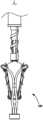
- Fig. 1is a schematic diagram of an open state of a tissue clipping system according to an embodiment
- Fig. 2is a schematic diagram of a closed state of a tissue clipping system according to an embodiment
- Fig. 3is a schematic diagram of the connection state of the support arm and the clamping arm of an embodiment
- Fig. 4is a schematic diagram of the connection state of the support arm and the clamping arm in another embodiment
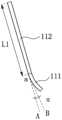
- Fig. 5is a structural schematic diagram of a support arm of an embodiment
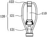
- Fig. 6is a structural schematic diagram of a clamping arm of an embodiment
- Fig. 7is a structural schematic diagram of another angle of the clamping arm of an embodiment
- Fig. 8is a schematic diagram of the positional relationship between two clamping arms in a closed state according to an embodiment
- Fig. 9is a schematic structural view of a clamping arm of an embodiment
- Fig. 10is a schematic diagram of the positional relationship of another angle of the two clamping arms shown in Fig. 8;
- Fig. 11is a schematic diagram of a partial structure of a clamping arm of an embodiment
- Fig. 12is a partial structural schematic diagram of a clamping arm of an embodiment
- Fig. 13is a schematic diagram of an open state of the tissue clipping system of an embodiment
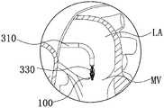
- 14 to 17are schematic diagrams of the implantation process of the tissue closure device of an embodiment.
- distal endis defined as the end away from the operator during the operation
- proximal endis defined as the end close to the operator during the operation.
- Axialrefers to the direction parallel to the line connecting the center of the distal end and the center of the proximal end of the medical device.
- the tissue clipping system 1 of an embodimentcomprises tissue clipping apparatus 100 and driving part 200 (in the state shown in Fig.
- the cooperation relationship with other componentsis represented by a dotted line driving part 200).
- the tissue clamping instrument 100is used for clamping tissues, wherein the aforementioned tissues include, but are not limited to, leaflets of the mitral valve, leaflets of the tricuspid valve, and the like.
- the driving part 200is used to drive the tissue clamping instrument 100, so that the tissue clamping instrument 100 can move between the open position and the closed position, that is, change between the open state and the closed state, so as to capture the tissue and then clamp the tissue.
- the state shown in FIG. 1is an open state
- the state shown in FIG. 2is a closed state.
- the tissue clamping instrument 100includes a clamping part 10 , a first supporting part 20 , a second supporting part 30 and a restricting part 40 .
- the clamping part 10includes at least two supporting arms 110 and at least two clamping arms 120 corresponding to the at least two supporting arms 110 one-to-one.
- the two supporting arms 110are disposed on the first supporting portion 20 .
- the two support arms 110are arranged symmetrically with the axial central axis of the first support portion 20 as the axis of symmetry.
- the two clamping arms 120are disposed on the second supporting portion 30 .
- the two clamping arms 120are arranged symmetrically with the axial central axis of the second support portion 30 as the axis of symmetry.
- the axial central axis of the first support part 20 and the axial central axis of the second support part 30are collinear or coincident with the axial central axis I-I of the tissue clamping instrument 100 .
- the axial central axis of the driving part 200is collinear or coincident with the axial central axis I-I of the tissue clamping instrument 100 .
- the two support arms 110can be radially expanded or closed relative to the axial central axis I-I of the tissue clamping instrument 100, and the two clamping arms 120 can be opened relative to the axial center of the tissue clamping instrument 100.
- Axis I-Iexpands or closes radially.
- one end of the support arm 110is rotatably connected to the first support part 20, so that driven by the driving component 200, the support arm 110 can expand radially relative to the axial central axis I-I of the tissue clamping instrument 100. or closed.
- the material of the support arm 110is elastic metal, such as nickel-titanium alloy, elastic stainless steel and other materials.
- the support arm 110is a sheet structure, a rod structure, or a coil structure.
- One end of the clamping arm 120is fixedly connected to the second support part 30, and one end of the support arm 110 away from the first support part 20 is rotatably connected to the other end of the clamping arm 120, so that when the driving part 200 moves in the axial direction, it can Simultaneously, the supporting arm 110 and the clamping arm 120 are radially expanded or closed. That is, the support arm 110 and the clamp arm 120 are movable between an open position (as shown in FIG. 1 ) and a closed position (as shown in FIG. 2 ).
- One end of the support arm 110 away from the first support portion 20is rotatably connected to the other end of the clamping arm 120 , for example, the rotatable connection can be realized through a rotating shaft, a pin shaft or a living hinge.
- the support arm 110includes a curved section 111 and a straight section 112 .
- One end of the curved section 111is fixedly connected to the straight section 112 , and the other end is rotatably connected to the clamping arm 120 .
- An end of the straight section 112 away from the curved section 111is rotatably connected to the first supporting portion 20 .
- one end of the curved section 111is fixedly connected with the straight section 112, the other end is rotatably connected with the first support part 20, and the end of the straight section 112 away from the curved section 111 is connected with the clamping arm 120 rotatable connections.
- the length of the straight section 112is L1
- the arc length of the curved section 111is L2 (not shown)
- L2/L11/5 ⁇ 1/3. Setting the lengths of the straight section 112 and the curved section 111 in this way, on the one hand, prevents the length of the curved section 111 from being too large, so as to ensure that there is enough stretching force to be transmitted to the clamping arm 120, that is, to ensure that the support arm 110 can provide a certain amount of stretching.
- the clamping arm 120can be stretched; on the other hand, avoid the length of the curved section 111 being too small, so that in the opening process, the curved section 111 can be further deformed (further bent) to relieve stress Too big a problem.
- the angle ⁇ of the curved section 111ranges from 10° to 45°. Within this angle range, it is guaranteed that the support arm 110 can transmit the stretching force under a certain force. to the clamping arm 120, and the curved section 111 can be deformed to a certain extent to alleviate the problem of excessive stress.
- the angle ⁇refers to the angle between the extension line A of the straight section 112 and the tangent line B of the curved section 111 , and the tangent line B and the extension line A intersect at the intersection a of the extension line A and the bending section 111 .
- the intersection point ais the tangent point of the tangent line B.
- the length of the straight section 112is L1
- the angle ⁇ of the curved section 111ranges from 10° to 45°, so that the opening of the clamping arm 120 is relatively easy, and it is relatively easy to capture the tissue, which is convenient for operation, so that the operation can be carried out smoothly, and it is beneficial to reduce the operation time.
- the support arm 110may be a one-piece structure made of metal wire or sheet, which has a corresponding curved shape after heat setting treatment, forming a curved section 111 and a straight section 112 .
- the bending degree of the bending section 111increases. That is, the bending section 111 can guide the support arm 110 to deform in a bending direction when the force exceeds a certain limit, and plays a buffering role.
- the clamping arm 120is easier to open.
- the clamping arm 120is substantially a wire loop structure with an opening.
- the clamping arm 120may be a wire loop wound from nickel titanium wire with an opening.
- One end of the supporting arm 110 connected to the clamping arm 120is bent or wound to enclose the clamping arm 120 , so as to realize the rotatable connection between the supporting arm 110 and the clamping arm 120 .
- This connection modeis through the mutual cooperation of the structures of the support arm 110 and the clamping arm 120 , so that the support arm 110 and the clamping arm 120 can pivot relative to each other without using connecting parts such as rotating shafts and pins.
- This pivotal connectionreduces the use of parts such as rotating shafts and pins, and can provide flexible rotation.
- end of the support arm 110 bent or curled to enclose the clamping arm 120can be the end of the curved section 111 away from the straight section 112 , or the end of the straight section 112 away from the curved section 111 .
- the clamping arm 120includes two supporting sections 121 and a connecting section 122 , both of which are metal rods. Two ends of the connection section 122 are respectively connected to two support sections 121 , and the ends of the two support sections 121 away from the connection section 122 are not connected to form a wire loop structure with an opening. One end of the connecting section 122 is the free end of the clamping arm 120 .
- the support arm 110is rotatably connected to the connecting section 122 .
- each support section 121includes a curved section 1211 and an extension section 1212 connected to the curved section 1211 .
- the end of the curved section 1211 away from the extension section 1212is bent toward the first direction, so that the end of the curved section 1211 away from the extension section 1212 and the extension section 1212 are not in the same plane.
- the connecting section 122 of the clamping arm 120is away from the axial central axis I-I of the tissue clamping instrument 100 .
- the curved section 1211is bent toward the first direction, and the bending of the curved section 1211 makes the end of the curved section 1211 away from the extension section 1212 and the extension section 1212 not in the same plane
- the free ends of the two clamping arms 120are away from the axial central axis I-I, that is, the two connecting sections 122 of the two clamping arms 120 are away from the axial central axis I-I and are in a state of being far away from each other, so that the clamping arms 120 It is more convenient to open.
- the first directionfor example, as shown in FIG. 8 , may be a direction away from the connecting section 122 of the other clamping arm 120, and the end of the curved section 1211 away from the extending section 1212 is not in the same plane as the extending section 1212 .
- the extension section 1212is straight rod-shaped, and the part where the extension section 1212 is connected to the curved section 1211 is on the same plane as the extension section 1212 .
- the extension segment 1212includes a curved rod 1212A and a straight rod 1212B connected to the curved rod 1212A, and an end of the curved rod 1212A away from the straight rod 1212B is connected to the curved segment 1211 .
- the bending rod 1212Abends to the second direction, so that the bending rod 1212A and the bending segment of a clamping arm 120 The connecting part of 1211 and the connecting part of the bending rod 1212A of the other clamping arm 120 and the bending segment 1211 (the circled part indicated by X in FIG.
- the second directionmay be the direction outside the wire loop, that is, the center of the bending rod 1212A itself is located inside the wire loop.
- the connecting portion of the bending rod 1212A and the bending segment 1211 of each clamping arm 120is in the shape of a straight rod, so that the area of the abutting portion of the two clamping arms 120 is larger and more reliable. to touch.
- the angle ⁇ of the bending rod 1212Ais 5°-15°, so that the connecting parts of the extension section 1212 and the bending section 1211 of the two clamping arms 120 can reliably abut against each other.
- the angle ⁇refers to the angle formed by the intersection of the tangent C and the tangent D of the bending rod 1212A, and the intersection point is b.
- Tangent Cintersects the junction of curved rod 1212A and straight rod 1212B
- tangent Dintersects the junction of curved rod 1212A and curved segment 1211 .
- the angle ⁇ of the curved section 1211is 10°-60°, so as to facilitate the opening of the clamping arm 120, and when the length of the curved section 1211 is constant, the angle ⁇ of the curved section 1211
- the portion where the curved rod 1212A connectsie, the portion of the curved segment 1211 that is coplanar with the curved rod 1212A) is long enough to maintain the clamping action.
- the angle ⁇refers to the angle between the extension line E of the connecting part of the bending rod 1212A and the bending section 1211 and the tangent line F of the bending section 1211, and the tangent line F intersects the extension line E at the intersection point of the extension line E and the bending section 1112 at c.
- first support portion 20 and the second support portion 30are axially opposite, coaxial and spaced apart.
- the first supporting portion 20is substantially columnar.
- An end of the support arm 110 away from the clamping arm 120is rotatably connected to the first support portion 20 .
- itis connected by means of a rotating shaft, so that the supporting arm 110 can rotate relative to the first supporting part 20 .
- a first through hole(not shown) is opened in the middle of the first supporting portion 20 .
- the second supporting portion 30includes a base 310 and a guide 320 disposed on the base 310 .
- the base 310is roughly a cylindrical structure
- the guide 320is a hollow cylindrical structure.
- the guide piece 320axially extends from a side of the base 310 close to the first support part 20 in a direction close to the first support part 20 .
- the base 310 and the guide 320may be of an integral structure.
- the base 310 and the guide member 320may be fixedly connected by means known to those skilled in the art, including but not limited to welding, bonding, and the like.
- An end of the clamping arm 120 away from the supporting arm 110is fixedly connected to the second supporting part 30 .
- the clamping arm 120is connected to the base 310 of the second supporting part 30 through the supporting section 121 .
- An end of the straight rod 1212B of the support section 121 away from the curved rod 1212Ais fixedly connected to the base 310 .
- the constraint portion 40is a hollow tube.
- the constraint part 40passes through the first support part 20 from the first through hole of the first support part 20 , and is fixedly connected with the first support part 20 .
- the constraint part 40protrudes from the first support part 20 , so that the distal end surface 401 of the constraint part 40 is spaced from the distal end surface 201 of the first support part 20 .
- the constraining part 40has a certain rigidity.
- the constraining part 40is a nickel-titanium tube, a stainless steel tube, or the like.
- the outer diameter of the constraint part 40is smaller than the inner diameter of the guide piece 320 .
- the tissue clamping instrument 100further includes a sealing part 50 sleeved on the constraining part 40 . Moreover, one end of the sealing part 50 is fixedly connected with the first support part 20, and the other end of the sealing part 50 is used for connecting with the delivery system.
- the sealing part 50is provided, and the sealing part 50 can seal and fill the gap between two tissues, which is beneficial to further improve the sealing effect.
- the sealing part 50is made of an elastic material, so that the sealing part 50 has a certain deformation ability, and after clamping, the sealing part 50 can play a certain buffering effect, so that the clamped two tissues (such as two leaflets) will not be pulled together, which can relieve the clamping stress.
- the shape of the sealing part 50is not limited, as long as it can play the role of sealing and cushioning.
- the sealing portion 50is cylindrical.
- the sealing portion 50has a structure in which axially opposite ends are small and the middle is large.
- the shape of the sealing portion 50matches the shape of the clamping arm 120 , so that in the clamping state, the outer surface of the sealing portion 50 completely fills the wire loop of the clamping arm 120 , thereby improving the sealing effect.
- a film(not shown) is disposed on the sealing portion 50 , and the film covers the surface of the sealing portion 50 to further improve the sealing effect.
- the driving part 200is a rod-shaped structure, and the outer diameter of the driving part 200 is smaller than the inner diameter of the restricting part 40 .
- the driving part 200is detachably connected to the second supporting part 30 .
- the driving component 200is detachably connected to the second supporting part 30 through threads.
- a threaded holeis opened in the base 310 of the second supporting part 30 , and the distal end of the driving component 200 is provided with a thread matched with the threaded hole to realize a detachable connection.
- the driving component 200can movably pass through the constraint portion 40 and can slide axially along the constraint portion 40 .
- the movement of the tissue clamping instrument 100 between the open position and the closed positionis achieved by the axial sliding of the drive member 200 .
- the support arm 110expands radially and spreads the clamping arm 120, so that the clamping arm 120 also expands radially.
- the clamping arm 120moves in the closing direction along with the supporting arm 110 .
- the tissue clamping instrument 100further includes a grasping portion 60 .
- there are two gripping portions 60and the two gripping portions 60 are disposed on two sides of the sealing portion 50 .
- One end of each catch portion 60is connected to the first supporting portion 20 , and the other end is a free end.
- the grasping part 60is used for grasping tissue, so as to improve operation efficiency and success rate.
- the gripping portion 60includes a main body 610 and a plurality of anchors 620 disposed on the main body 610 at intervals.
- One end of the main body 610is connected to the first supporting part 20 , and the other end is a free end.
- One end of the anchoring member 620is connected to the main body 610 at an acute angle, and the other end is a free end, which protrudes outward and faces the support arm 110 .
- the distal end of the delivery sheath 310reaches the left atrium LA by passing the delivery sheath 310 through the femoral vein and the inferior vena cava to the right atrium RA, and then puncturing the interatrial septum AS.
- the tissue clipping instrument 100is pushed out from the delivery sheath 310, as shown in FIG. 15 Show. Further, please refer to FIG.
- the tissue clamping instrument 100push the tissue clamping instrument 100 to the position of the mitral valve MV, and adjust the position (if necessary), so that the clamping arm 120 of the tissue clamping instrument 100 is located near the left ventricle of the mitral valve leaflet LV side.
- the driving part 200is moved in the axial direction, so that the support arm 110 and the clamping arm 120 are in an open state, so as to capture the leaflet.
- the angle of the grasping part 60is controlled by the control wire 330 to catch the leaflet.
- the driving part 200is moved axially to move the support arm 110 and the clamping arm 120 from the open position to the closed position, thereby clamping the leaflet between the grasping part 60 and the valve leaflet. Between the support arms 110 , as shown in FIG. 17 , the opening area of the mitral valve MV is reduced.
- the control wire 330is withdrawn, the connection between the driving part 200 and the second support base 30 is released, the connection between the connector and the tissue closure device 100 is released, and the conveyor is withdrawn to complete the operation.
- the distal end of the restriction part 40is accommodated in the guide part 320 , so that the distal end of the driving part 200 is covered by the restriction part 40 and the guide part 320 and constrained by the restriction part 40 and the guide part 320 at the same time.
- the force generated on the clamping arm 120is the largest, and the constraint part 40, the guide member 320 and the driving part 200 form a rigid guiding structure, and the rigid guiding structure
- the role of positioning and guidingis conducive to the stable transmission of the force and the uniform distribution to both sides, which can prevent the clamping arms 120 from shifting, so that the two clamping arms 120 on both sides can be opened synchronously and stably.
- the distal end of the constraining portion 40is accommodated in the guide 320, and the distal end of the driving component 200 is covered by the constraining portion 40 and the guide 320, which plays a role in enhancing rigidity, maximizes the effective transmission force of the drive, and makes it easier to drive.
- the action of the clamp arm 120is opened.
- the driving part 200 with a smaller outer diametercan be used, so that the overall flexibility of the tissue clipping system 1 is better, and it is convenient to pass through a curved lumen.
- the distal end of the constraining portion 40is accommodated in the guide 320 .
- the size of the included angle ⁇ between the two support arms 110is 60°-150°
- the distal end of the retaining constraining portion 40is accommodated in the guide 320, and the distal end of the driving component 200 is enclosed by the constraining portion 40 and the guide 320 Covering, so that the left and right sides of the axial central axis I-I of the tissue clamping instrument 100 are evenly stressed, which is conducive to ensuring that no deviation occurs during the subsequent opening process and subsequent closing process, thereby improving the clamping effect.
- the distal end of the constraining portion 40is accommodated in the guide 320 to ensure that no deviation occurs during the further opening process and the subsequent closing process. shift, thereby improving the clamping effect.
- the angle ⁇ between the two support arms 110is greater than 180°, which is the state ready to retract, that is, the transition point between the open state and the closed state.
- the distal end of the restricting part 40is separated from the guide part 320 , and the distal end surface 401 of the restricting part 40 is spaced from the proximal end surface 321 of the guide part 320 , exposing the driving part 200 .
- the distal end of the driving part 200is still connected to the base 310 .
- angle ⁇ between the two support arms 110refers to the angle formed by the two support arms 110 on the side away from the second support portion 30 .
- the above-mentioned tissue clipping system 1is provided with a constraining part 40 and a second support part 30 including a guide 320, the driving part 200 passes through the constraining part 40, and in the closed state, the distal end of the constraining part 40 is accommodated in the guide 320 Among them, the restraint part 40 and the guide piece 320 enclose the driving part 200, which can form a better restraint and strengthening effect on the driving part 200, and is beneficial to the moment when the support arm 110 just radiates outwards or opens, the support arm 110 and the clip
- the closing arm 120is under stable force, so that there is no deviation during the subsequent further opening and subsequent closing process, and the clamping effect is better.
- the base 310 in the second supporting part 30may be omitted.
- the clamping arm 120is directly connected to the guide 320 , for example, the straight rod 1212B of the clamping arm 120 is directly connected to the outer wall of the guide 320 .
- the far end of driving part 200is provided with the connecting part that is screwed with the inner wall of guide part 320, and the outer diameter of connecting part is larger than the outer diameter of the rest of driving part 200, so that when driving part 200 is kept connected with guide part 320 In this state, the distal end of the constraining part 40 can be accommodated in the guide 320 .
- the support arm 110 of the tissue closure instrument 100includes a curved section 111 and a straight section 112, during the opening process, the component force applied by the support arm 110 to the opening direction of the clamping arm 120 increases, so that the clamping arm 120 Opening is easier, which increases the safety of manipulating the system.
- the free ends of the two clamping arms 120are far away from the axial central axis I-I, so that the opening of the clamping arms 120 is easier, and the support arms can be opened with less force.
- 110stretches the clamping arm 120 to move the connecting section 122 of the clamping arm 120 in a direction away from the axial central axis I-I so that the clamping arm 120 is in an open state.
- the two clamping arms 120can reliably clamp the sealing part 50, To avoid falling off and maintain sealing performance.
- the sealing part 50can be omitted.
- the two clamping arms 120 surrounding the two sides of the constraining part 40are close to each other and resist each other, which can also achieve a better sealing effect. Clipping effect.
- providing the sealing portion 50can further improve the clamping effect and the sealing effect.
Landscapes
- Health & Medical Sciences (AREA)
- Life Sciences & Earth Sciences (AREA)
- Surgery (AREA)
- Heart & Thoracic Surgery (AREA)
- Public Health (AREA)
- Vascular Medicine (AREA)
- Engineering & Computer Science (AREA)
- Biomedical Technology (AREA)
- Veterinary Medicine (AREA)
- General Health & Medical Sciences (AREA)
- Animal Behavior & Ethology (AREA)
- Cardiology (AREA)
- Molecular Biology (AREA)
- Medical Informatics (AREA)
- Nuclear Medicine, Radiotherapy & Molecular Imaging (AREA)
- Reproductive Health (AREA)
- Oral & Maxillofacial Surgery (AREA)
- Transplantation (AREA)
- Surgical Instruments (AREA)
Abstract
Description
Translated fromChinese本发明涉及医疗器械领域,特别是涉及一种组织夹合系统。The invention relates to the field of medical instruments, in particular to a tissue clipping system.
本部分提供的仅仅是与本公开相关的背景信息,其并不必然是现有技术。This section provides background information related to the present disclosure only and is not necessarily prior art.
二尖瓣疾病是老年人群中的一种常见疾病。目前经导管二尖瓣修复产品已有产品上市。Mitral valve disease is a common disease in the elderly population. At present, products for transcatheter mitral valve repair have been launched.
现有的经导管二尖瓣修复产品的原理均为采用一个夹合器械将二尖瓣瓣膜的前叶和后叶进行夹合,使瓣膜开口面积减小,从而达到治疗返流的目的。现有的产品中,有的为机械锁定的夹合器械,其在介入操作中需要打开锁定,才能执行夹合操作,因此操作复杂。并且,因为是机械锁定式,夹合应力不可控制,因此器械对瓣叶的损伤较大。为了避免这个问题,有的采用弹性夹合方式,使瓣叶夹合在弹性夹合臂之间,缓和瓣叶夹合的应力,降低瓣叶损伤。在瓣叶捕获前需要采用一定的机构撑开弹性夹合臂,弹性夹合臂具有一定的柔性,稳定性较差,可能在打开的过程中发生偏位,影响最终瓣膜夹合的效果。The principle of the existing transcatheter mitral valve repair products is to use a clamping device to clamp the anterior leaflet and the posterior leaflet of the mitral valve to reduce the valve opening area, thereby achieving the purpose of treating regurgitation. Among the existing products, some are mechanically locked clamping instruments, which need to be unlocked during the intervention operation to perform the clamping operation, so the operation is complicated. Moreover, because it is a mechanical locking type, the clamping stress cannot be controlled, so the damage of the instrument to the valve leaflet is relatively large. In order to avoid this problem, some adopt the elastic clamping method, so that the valve leaflets are clamped between the elastic clamping arms, so as to relieve the stress of the valve leaflet clamping and reduce the damage of the valve leaflets. Before the valve leaflets are captured, a certain mechanism needs to be used to expand the elastic clamping arms. The elastic clamping arms have certain flexibility and poor stability, and may deviate during the opening process, affecting the final valve clamping effect.
为了解决上述问题,本领域技术人员容易想到对弹性的夹合臂进行改进、优化。然而,夹合效果有必要进一步优化。In order to solve the above problems, those skilled in the art can easily think of improving and optimizing the elastic clamping arm. However, the clamping effect needs to be further optimized.
发明内容Contents of the invention
基于此,有必要提供一种夹合效果较好的组织夹合系统。Based on this, it is necessary to provide a tissue clamping system with better clamping effect.
一种组织夹合系统,包括组织夹合器械和驱动部件,所述组织夹合器械包括夹合部、第一支撑部、第二支撑部和约束部,所述夹合部包括至少两个支撑臂和与所述至少两个支撑臂一一对应的至少两个夹合臂,所述至少两个支撑臂设于所述第一支撑部上,所述至少两个夹合臂设于所述第二支撑部上,所述第二支撑部包括导向件,所述约束部穿设所述第一支撑部并与所述第一支撑部固定连接,所述驱动部件穿设所述约束部且所述驱动部件与所述第二支撑部可拆 卸连接,所述驱动部件用于驱动所述至少两个支撑臂相对所述约束部呈辐射状展开或闭合,使所述至少两个夹合臂相对所述约束部呈辐射状展开或闭合;在闭合状态下,所述约束部的远端收容于所述导向件中,使得在所述支撑臂刚展开的瞬间,所述约束部的远端收容于所述导向件中。A tissue clamping system, comprising a tissue clamping instrument and a driving part, the tissue clamping instrument comprises a clamping part, a first support part, a second support part and a constraint part, the clamping part comprises at least two supports arm and at least two clamping arms corresponding to the at least two supporting arms one by one, the at least two supporting arms are set on the first support part, and the at least two clamping arms are set on the On the second support part, the second support part includes a guide piece, the restriction part passes through the first support part and is fixedly connected with the first support part, the driving part passes through the restriction part and The driving part is detachably connected to the second supporting part, and the driving part is used to drive the at least two supporting arms to expand or close radially relative to the constraining part, so that the at least two clamping arms It is radially expanded or closed relative to the constraint part; in the closed state, the distal end of the constraint part is accommodated in the guide, so that at the moment when the support arm is just deployed, the distal end of the constraint part accommodated in the guide.
在其中一个实施例中,当两个所述支撑臂的夹角为60°~150°时,所述约束部的远端收容于所述导向件中。In one of the embodiments, when the included angle between the two support arms is 60°-150°, the distal end of the restriction part is accommodated in the guide piece.
在其中一个实施例中,当两个所述支撑臂的夹角为120°时,所述约束部的远端收容于所述导向件中。In one of the embodiments, when the included angle between the two support arms is 120°, the distal end of the restriction part is accommodated in the guide member.
在其中一个实施例中,所述组织夹合器械还包括密封部,所述密封部套设于所述约束部上。In one of the embodiments, the tissue clamping instrument further includes a sealing part, and the sealing part is sleeved on the restricting part.
在其中一个实施例中,所述支撑臂的一端与所述第一支撑部可转动连接,所述夹合臂的一端与所述第二支撑部固定连接,且所述支撑臂的另一端与所述夹合臂的另一端可转动连接。In one embodiment, one end of the support arm is rotatably connected to the first support part, one end of the clamping arm is fixedly connected to the second support part, and the other end of the support arm is connected to the second support part. The other end of the clamping arm is rotatably connected.
在其中一个实施例中,所述支撑臂包括弯曲段及直伸段,所述弯曲段的一端与所述直伸段固定连接,另一端与所述夹合臂可转动连接;或者,所述弯曲段的一端与所述直伸段固定连接,所述直伸段的远离所述弯曲段的一端与所述夹合臂可转动连接。In one embodiment, the support arm includes a curved section and a straight section, one end of the curved section is fixedly connected to the straight section, and the other end is rotatably connected to the clamping arm; or, the curved section One end of the straight section is fixedly connected to the straight section, and the end of the straight section away from the curved section is rotatably connected to the clamping arm.
在其中一个实施例中,在闭合位置,所述弯曲段呈弯曲状态,且当所述夹合臂和所述支撑臂从闭合位置运动至打开位置的过程中,所述弯曲段的弯曲程度增加。In one embodiment, in the closed position, the curved section is in a curved state, and when the clamping arm and the supporting arm move from the closed position to the open position, the bending degree of the curved section increases .
在其中一个实施例中,所述夹合臂包括连接段和两个支撑段,所述连接段的两端分别连接所述两个支撑段,且所述连接段所在的一端为所述夹合臂的自由端,每个所述支撑段包括弯曲节段和延伸节段,所述弯曲节段的一端与所述延伸节段相连,另一端与所述连接段相连,且所述弯曲节段的远离所述延伸节段的一端与所述延伸节段不在同一平面内,使所述连接段远离所述组织夹合器械的轴向中心轴线。In one of the embodiments, the clamping arm includes a connecting section and two supporting sections, the two ends of the connecting section are respectively connected to the two supporting sections, and one end where the connecting section is located is the clamping arm. The free end of the arm, each of the support sections includes a curved section and an extension section, one end of the curved section is connected to the extension section, the other end is connected to the connecting section, and the curved section The end of the extension segment away from the extension segment is not in the same plane as the extension segment, so that the connecting segment is away from the axial central axis of the tissue clamping instrument.
在其中一个实施例中,所述延伸节段包括弯曲杆和与所述弯曲杆相连的直杆,所述弯曲杆的远离所述直杆的一端与所述弯曲节段相连。In one embodiment, the extension segment includes a curved rod and a straight rod connected to the curved rod, and an end of the curved rod far away from the straight rod is connected to the curved segment.
在其中一个实施例中,所述夹合臂为两个,在闭合状态下,其中一个夹合臂的所述弯曲杆和所述弯曲段的连接部位与另一个所述夹合臂的所述弯曲杆和所述弯曲节段的连接部位相互抵持。In one of the embodiments, there are two clamping arms, and in the closed state, the connecting portion of the bending rod and the bending section of one clamping arm is connected to the connecting portion of the other clamping arm. The connecting points of the curved rod and the curved segment bear against each other.
上述组织夹合系统中设置有约束部及包括导向件的第二支撑部,驱动部件穿设约束部,且在闭合状态下,约束部的远端收容于导向件中,约束部和导向件包住驱动部件,能够对驱动部件形成较好的约束和加强作用,有利于在支撑臂刚展开的瞬间,支撑臂和夹合臂受力稳定,从而在后续进一步打开和后续闭合过程中不发生偏移,夹合效果较好。The above-mentioned tissue clipping system is provided with a constraining part and a second support part including a guide, the driving part passes through the constraining part, and in the closed state, the distal end of the constraining part is accommodated in the guide, and the constraining part and the guide comprise Hold the driving part, which can form a better restraint and reinforcement effect on the driving part, which is conducive to the stability of the force on the support arm and the clamping arm at the moment when the support arm is just unfolded, so that no deviation will occur in the subsequent further opening and subsequent closing processes. Move, clamping effect is better.
图1为一实施例的组织夹合系统的打开状态示意图;Fig. 1 is a schematic diagram of an open state of a tissue clipping system according to an embodiment;
图2为一实施例的组织夹合系统的闭合状态示意图;Fig. 2 is a schematic diagram of a closed state of a tissue clipping system according to an embodiment;
图3为一实施例的支撑臂与夹合臂的连接状态示意图;Fig. 3 is a schematic diagram of the connection state of the support arm and the clamping arm of an embodiment;
图4为另一实施例的支撑臂与夹合臂的连接状态示意图;Fig. 4 is a schematic diagram of the connection state of the support arm and the clamping arm in another embodiment;
图5为一实施例的支撑臂的结构示意图;Fig. 5 is a structural schematic diagram of a support arm of an embodiment;
图6为一实施例的夹合臂的结构示意图;Fig. 6 is a structural schematic diagram of a clamping arm of an embodiment;
图7为一实施例的夹合臂的另一角度的结构示意图;Fig. 7 is a structural schematic diagram of another angle of the clamping arm of an embodiment;
图8为一实施例在闭合状态的两个夹合臂位置关系示意图;Fig. 8 is a schematic diagram of the positional relationship between two clamping arms in a closed state according to an embodiment;
图9为一实施例的夹合臂的结构示意图;Fig. 9 is a schematic structural view of a clamping arm of an embodiment;
图10为图8所示的两个夹合臂的另一角度的位置关系示意图;Fig. 10 is a schematic diagram of the positional relationship of another angle of the two clamping arms shown in Fig. 8;
图11为一实施例的夹合臂的局部结构示意图;Fig. 11 is a schematic diagram of a partial structure of a clamping arm of an embodiment;
图12为一实施例的夹合臂的局部结构示意图;Fig. 12 is a partial structural schematic diagram of a clamping arm of an embodiment;
图13为一实施例的组织夹合系统的打开状态示意图;Fig. 13 is a schematic diagram of an open state of the tissue clipping system of an embodiment;
图14~图17为一实施例的组织闭合器械的植入过程示意图。14 to 17 are schematic diagrams of the implantation process of the tissue closure device of an embodiment.
为使本发明的上述目的、特征和优点能够更加明显易懂,下面结合附图对本发明的具体实施方式做详细的说明。在下面的描述中阐述了很多具体细节以 便于充分理解本发明。但是本发明能够以很多不同于在此描述的其它方式来实施,本领域技术人员可以在不违背本发明内涵的情况下做类似改进,因此本发明不受下面公开的具体实施的限制。In order to make the above objects, features and advantages of the present invention more comprehensible, specific implementations of the present invention will be described in detail below in conjunction with the accompanying drawings. In the following description, numerous specific details are set forth in order to provide a thorough understanding of the present invention. However, the present invention can be implemented in many other ways different from those described here, and those skilled in the art can make similar improvements without departing from the connotation of the present invention, so the present invention is not limited by the specific implementations disclosed below.
除非另有定义,本文所使用的所有的技术和科学术语与属于本发明的技术领域的技术人员通常理解的含义相同。本文中在本发明的说明书中所使用的术语只是为了描述具体的实施例的目的,不是旨在于限制本发明。Unless otherwise defined, all technical and scientific terms used herein have the same meaning as commonly understood by one of ordinary skill in the technical field of the invention. The terms used herein in the description of the present invention are for the purpose of describing specific embodiments only, and are not intended to limit the present invention.
在介入医疗器械领域,定义“远端”为手术过程中远离操作者的一端,定义“近端”为手术过程中靠近操作者的一端。“轴向”指平行于医疗器械远端中心和近端中心连线的方向。In the field of interventional medical devices, the "distal end" is defined as the end away from the operator during the operation, and the "proximal end" is defined as the end close to the operator during the operation. "Axial" refers to the direction parallel to the line connecting the center of the distal end and the center of the proximal end of the medical device.
请参阅图1,一实施例的组织夹合系统1,包括组织夹合器械100和驱动部件200(图1所示的状态中,不能看到驱动部件200,但为了清楚地示意出驱动部件200与其他元件的配合关系,用虚线表示驱动部件200)。组织夹合器械100用于夹合组织,其中,上述的组织包括但不限于,二尖瓣的瓣叶、三尖瓣的瓣叶等。驱动部件200用于驱动组织夹合器械100,使组织夹合器械100能够在打开位置和闭合位置之间运动,即在打开状态和闭合状态之间变化,以抓捕到组织后夹合组织。其中,图1所示的状态为打开状态,图2所示的状态为闭合状态。Please refer to Fig. 1, the tissue clipping system 1 of an embodiment, comprises
组织夹合器械100包括夹合部10、第一支撑部20、第二支撑部30和约束部40。The
夹合部10包括至少两个支撑臂110和与至少两个支撑臂110一一对应的至少两个夹合臂120。图1所示的实施例中,支撑臂110的数量为二,夹合臂120的数量为二。两个支撑臂110设置于第一支撑部20上。具体地,两个支撑臂110以第一支撑部20的轴向中心轴线为对称轴对称设置。两个夹合臂120设置于第二支撑部30上。具体地,两个夹合臂120以第二支撑部30的轴向中心轴线为对称轴对称设置。第一支撑部20的轴向中心轴线和第二支撑部30的轴向中心轴线与组织夹合器械100的轴向中心轴线I-I共线或重合。The clamping
驱动部件200的轴向中心轴线与组织夹合器械100的轴向中心轴线I-I共线或重合。在驱动部件200的驱动下,两个支撑臂110可相对组织夹合器械100 的轴向中心轴线I-I呈辐射状展开或闭合,两个夹合臂120可相对组织夹合器械100的轴向中心轴线I-I呈辐射状展开或闭合。The axial central axis of the driving
在一实施例中,支撑臂110的一端与第一支撑部20可转动连接,以在驱动部件200的驱动下,支撑臂110可相对组织夹合器械100的轴向中心轴线I-I呈辐射状展开或闭合。In one embodiment, one end of the
在一实施例中,支撑臂110的材料为弹性金属,例如为镍钛合金、弹性不锈钢等材料。In one embodiment, the material of the
在一实施例中,支撑臂110为片状结构、杆状结构或线圈结构等。In one embodiment, the
夹合臂120的一端与第二支撑部30固定连接,支撑臂110的远离第一支撑部20的一端与夹合臂120的另一端可转动连接,使得驱动部件200沿轴向移动时,能够同时使支撑臂110和夹合臂120向外辐射展开或闭合。即,支撑臂110和夹合臂120能够在打开位置(如图1所示)和闭合位置(如图2所示)之间运动。One end of the
支撑臂110的远离第一支撑部20的一端与夹合臂120的另一端可转动连接,例如,可以通过转轴、销轴或活动铰链等实现可转动连接。One end of the
请参阅图3,支撑臂110包括弯曲段111及直伸段112。弯曲段111的一端与直伸段112固定连接,另一端与夹合臂120可转动连接。直伸段112的远离弯曲段111的一端与第一支撑部20可转动连接。请参阅图4,在另一实施例中,弯曲段111的一端与直伸段112固定连接,另一端与第一支撑部20可转动连接,直伸段112的远离弯曲段111的一端与夹合臂120可转动连接。Please refer to FIG. 3 , the
请参阅图5,在一实施例中,直伸段112的长度为L1,弯曲段111的弧长为L2(图未示),L2/L1=1/5~1/3。如此设置直伸段112和弯曲段111的长度,一方面,避免弯曲段111的长度过大,以保证有足够的撑开力传递到夹合臂120,即保证支撑臂110能够提供一定的撑开力,使得在打开过程中,能够将夹合臂120撑开;另一方面,避免弯曲段111的长度过小,以在打开过程中,弯曲段111能够进一步变形(进一步弯曲),以缓解应力过大的问题。Please refer to FIG. 5 , in one embodiment, the length of the
请继续参阅图5,在一实施例中,弯曲段111的角度α的范围为10°~45°,在该角度范围内,保证在一定的力作用下,支撑臂110能够将撑开力传递至夹 合臂120上,且弯曲段111能够在一定程度上变形而减缓应力过大的问题。其中,角度α是指直伸段112的延长线A与弯曲段111的切线B的夹角,切线B与延长线A相交于延长线A与弯曲段111的交点a处。交点a为切线B的切点。Please continue to refer to FIG. 5. In one embodiment, the angle α of the
当支撑臂110的长度确定时,弯曲段111的角度α越大,则支撑臂110的捕获长度越小,越难以捕获组织。当弯曲段111的角度α过小,则难以实现容易打开夹合臂120作用。因此,在一实施例中,直伸段112的长度为L1,弯曲段111的弧长为L2,L2/L1=1/5~1/3,并且弯曲段111的角度α的范围为10°~45°,以使夹合臂120的打开较为容易,且较为容易地捕获到组织,方便操作,使手术顺利进行,有利于减少手术时间。When the length of the
在一实施例中,支撑臂110可以为由金属丝材或片材制成的一体式结构,经过热定型处理后具有相应的弯曲形状,形成弯曲段111和直伸段112。In one embodiment, the
在一实施例中,当支撑臂110和夹合臂120从闭合位置运动至打开位置的过程中,弯曲段111的弯曲程度增加。即弯曲段111在受力超过一段限度时可以引导支撑臂110朝向弯曲的方向变形,起到缓冲作用。当支撑臂110变形到一定程度时,夹合臂120更容易打开。In one embodiment, when the supporting
在一实施例中,如图6所示,夹合臂120大致为具有开口的线环结构。例如,夹合臂120可以是镍钛丝绕成的具有开口的线环。支撑臂110与夹合臂120连接的一端弯曲或卷绕而包住夹合臂120,以实现支撑臂110与夹合臂120可转动连接。这种连接方式是通过支撑臂110和夹合臂120自身的结构相互配合,使得在不使用转轴、销钉等连接件的情况,支撑臂110和夹合臂120可以相对枢转。这种枢转连接方式,减少了转轴、销钉等零件的使用,且可以提供灵活地转动。In one embodiment, as shown in FIG. 6 , the clamping
可以理解,支撑臂110的弯曲或卷曲而包住夹合臂120的一端可以为弯曲段111的远离直伸段112的一端,也可以为直伸段112的远离弯曲段111的一端。It can be understood that the end of the
请参阅图7,在一实施例中,夹合臂120包括两个支撑段121和连接段122,支撑段121和连接段122均为金属杆。连接段122的两端分别连接两个支撑段121,且两个支撑段121的远离连接段122的一端不相连而形成具有开口的线环结构。连接段122所在的一端为夹合臂120的自由端。支撑臂110与连接段122 可转动连接。Referring to FIG. 7 , in one embodiment, the clamping
请一并参阅图8,在一实施例中,每个支撑段121包括弯曲节段1211和与弯曲节段1211相连的延伸节段1212。其中,弯曲节段1211的远离延伸节段1212的一端向第一方向弯曲,使得弯曲节段1211的远离延伸节段1212的一端和延伸节段1212不在同一平面内。并且,由于弯曲节段1211的远离延伸节段1212的一端向第一方向弯曲,使得夹合臂120的连接段122远离组织夹合器械100的轴向中心轴线I-I。Please refer to FIG. 8 together. In one embodiment, each
如图8所示,在自然状态下,弯曲节段1211向第一方向弯曲,并且,弯曲节段1211的弯曲使得弯曲节段1211的远离延伸节段1212的一端与延伸节段1212不在同一平面内,使得两个夹合臂120的自由端远离轴向中心轴线I-I,即两个夹合臂120的两个连接段122远离轴向中心轴线I-I而呈相互远离的状态,使得夹合臂120的打开较为方便。第一方向,例如,如图8所示,可以为远离另一个夹合臂120的连接段122的方向,且弯曲节段1211的远离延伸节段1212的一端与延伸节段1212不在同一平面内。As shown in FIG. 8 , in the natural state, the
在一实施例中,延伸节段1212为直杆状,并且延伸节段1212与弯曲节段1211相连的部位与延伸节段1212在同一平面上。In one embodiment, the
请参阅图9,在一实施例中,延伸节段1212包括弯曲杆1212A及与弯曲杆1212A相连的直杆1212B,弯曲杆1212A远离直杆1212B的一端与弯曲节段1211相连。请一并参阅图8和图10,在一实施例中,在自然状态(亦为闭合状态)下,弯曲杆1212A向第二方向弯曲,使得一个夹合臂120的弯曲杆1212A和弯曲节段1211的连接部位与另一个夹合臂120的弯曲杆1212A和弯曲节段1211的连接部位(图10中X指示的圆圈部位)较为可靠地抵接在一起,形成抵持部位。在抵持部位,由于夹合臂120具有弹性,使得两个夹合臂120相互提供相向的抵持力,从而使得两个夹合臂120较为可靠地抵接在一起,有利于提高夹合的可靠性,以避免因心脏的收缩和舒张运动而使组织夹合器械100脱落。第二方向,例如,如图9所示,可以为线环外部的方向,即弯曲杆1212A自身的圆心位于线环内部。Referring to FIG. 9 , in one embodiment, the
在一实施例中,每个夹合臂120的弯曲杆1212A和弯曲节段1211的连接部 位呈直杆状,使得两个夹合臂120的相互抵接的部位的面积较大,更为可靠地抵接。In one embodiment, the connecting portion of the bending
请参阅图11,在一实施例中,弯曲杆1212A的角度β为5°~15°,以使两个夹合臂120的延伸节段1212和弯曲节段1211的连接部位能够可靠地抵接在一起。其中,角度β是指弯曲杆1212A的切线C和切线D相交形成的角度,交点为b。切线C与弯曲杆1212A和直杆1212B的连接处相交,切线D与弯曲杆1212A和弯曲节段1211的连接处相交。Please refer to FIG. 11 , in one embodiment, the angle β of the bending
请参阅图12,在一实施例中,弯曲节段1211的角度γ为10°~60°,以方便打开夹合臂120,且当弯曲节段1211的长度一定时,使弯曲节段1211的与弯曲杆1212A连接的部位(即弯曲节段1211的与弯曲杆1212A共面的部位)足够长,以保持夹合作用。其中,角度γ是指弯曲杆1212A与弯曲节段1211的连接部位的延长线E与弯曲节段1211的切线F的夹角,切线F与延长线E相交于延长线E与弯曲段1112的交点c处。Please refer to Fig. 12, in one embodiment, the angle γ of the
如图13所示,第一支撑部20和第二支撑部30在轴向上相对,且同轴并间隔设置。As shown in FIG. 13 , the
在一实施例中,第一支撑部20大致为柱状结构。支撑臂110的远离夹合臂120的一端与第一支撑部20可转动连接。例如,采用转轴的方式连接,使得支撑臂110相对第一支撑部20可转动。第一支撑部20的中部开设有第一通孔(图未示)。In one embodiment, the first supporting
请继续参阅图13,第二支撑部30包括底座310和设置于底座310上的导向件320。底座310大致为圆柱状结构,导向件320为中空柱状结构。导向件320自底座310的靠近第一支撑部20的一侧向靠近第一支撑部20的方向轴向延伸。底座310和导向件320可以为一体式结构。或者,也可以采用本领域技术人员掌握的方式,包括但不限于焊接、粘接等方式,将底座310和导向件320固定连接。Please continue to refer to FIG. 13 , the second supporting
夹合臂120远离支撑臂110的一端与第二支撑部30固定连接。具体地,夹合臂120通过支撑段121与第二支撑部30的底座310相连。支撑段121的直杆1212B的远离弯曲杆1212A的一端与底座310固定连接。An end of the
请继续参阅图13,约束部40为中空管件。约束部40从第一支撑部20的第一通孔穿设第一支撑部20,并与第一支撑部20固定连接。约束部40伸出第一支撑部20,使得约束部40的远端端面401与第一支撑部20的远端端面201间隔。Please continue to refer to FIG. 13 , the
约束部40具有一定的刚性。在一实施例中,约束部40为镍钛管、不锈钢管等。约束部40的外径小于导向件320的内径。The constraining
在一实施例中,组织夹合器械100还包括密封部50,密封部50套设在约束部40上。并且,密封部50的一端与第一支撑部20固定连接,密封部50的另一端用于与输送系统连接。设置密封部50,密封部50能够密封填充两个组织之间的间隙,有利于进一步提高密封效果。在一实施例中,密封部50由弹性材料制成,使得密封部50具有一定的变形能力,在夹合后,密封部50能够起到一定缓冲作用,而使被夹合的两个组织(如两个瓣叶)不会被硬拉到一起,可以减缓夹合应力。In one embodiment, the
密封部50的形状不限,只要能够起到密封及缓冲作用的任何形状均可。在一实施例中,密封部50为圆柱状。在另一实施例中,密封部50为轴向相对的两端小,而中间大的结构。The shape of the sealing
在一实施例中,密封部50的形状与夹合臂120的形状相匹配,使得在夹合状态,密封部50外表面完全填充夹合臂120的线环,从而提高密封效果。In one embodiment, the shape of the sealing
在一实施例中,密封部50上设置有覆膜(图未示),覆膜包覆在密封部50的表面上,以进一步提高密封效果。In one embodiment, a film (not shown) is disposed on the sealing
驱动部件200为杆状结构,并且驱动部件200的外径小于约束部40的内径。驱动部件200与第二支撑部30可拆卸连接。The driving
在一实施例中,驱动部件200与第二支撑部30通过螺纹可拆卸连接。例如,第二支撑部30的底座310中开设有螺纹孔,驱动部件200的远端设置有与该螺纹孔配合的螺纹,以实现可拆卸连接。In one embodiment, the
并且,驱动部件200可活动地穿设约束部40,沿着约束部40轴向可滑动。通过驱动部件200的轴向滑动实现组织夹合器械100能够在打开位置和闭合位置之间运动。驱动部件200沿轴向向远端滑动时,支撑臂110呈辐射状展开而 将夹合臂120撑开,使得夹合臂120亦呈辐射状展开。当驱动部件200沿轴向向近端滑动时,夹合臂120随着支撑臂110向闭合方向运动。Moreover, the
请继续参阅图13,在一实施例中,组织夹合器械100还包括抓持部60。在一实施例中,抓持部60为两个,两个抓持部60围设于密封部50的两侧。每个抓捕部60的一端与第一支撑部20相连,另一端为自由端。抓持部60用于抓持组织,以提高手术效率和成功率。Please continue to refer to FIG. 13 , in an embodiment, the
在一实施例中,抓持部60包括主体610及间隔设置于主体610上的多个锚定件620。主体610的一端与第一支撑部20相连,另一端为自由端。锚定件620的一端与主体610成锐角连接,另一端为自由端,自由端向外伸出,且朝向支撑臂110。In one embodiment, the gripping
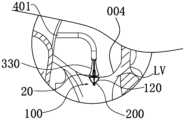
以待闭合组织为二尖瓣瓣叶为例说明组织夹合器械100的输送、释放和闭合过程。在一实施例中,如图14,通过输送鞘管310经股静脉、下腔静脉至右心房RA,然后穿刺房间隔AS,输送鞘管310的远端到达左心房LA。通过调控输送鞘管310的远端,使其居于二尖瓣MV上方的正中位置,然后通过操作手柄上的控制件,将组织夹合器械100从输送鞘管310中推送出来,如图15所示。进一步,请参阅图16,将组织夹合器械100推送至二尖瓣MV位置,并调整位置(如有必要),使得组织夹合器械100的夹合臂120位于二尖瓣叶的靠近左心室LV的一侧。通过操作手柄上的控制件,使驱动部件200沿轴向移动,从而使支撑臂110和夹合臂120呈现打开状态,以捕获瓣叶。接着,通过控制丝330控制抓持部60的角度,以捕捉瓣叶。当抓持部60捕获到瓣叶后,使驱动部件200沿轴向移动,以使支撑臂110和夹合臂120从打开位置向闭合位置运动,从而将瓣叶夹持在抓持部60和支撑臂110之间,如图17所示,从而实现二尖瓣MV的开口面积减小。夹合完成后,撤出控制丝330,解除驱动部件200与第二支撑座30的连接,解除连接件与组织闭合器械100的连接,撤回输送器,完成手术。The delivery, release and closure process of the
在闭合状态,约束部40的远端收容于导向件320中,使得驱动部件200的远端被约束部40和导向件320所包覆,同时被约束部40和导向件320所约束。当要打开组织夹合器械100时,在刚打开的瞬间,对夹合臂120所产生的作用 力最大,约束部40、导向件320和驱动部件200三者形成刚性导向结构,刚性导向结构的定位导向作用有助于作用力的稳定传递和向两侧均匀分散,能够避免夹合臂120偏移,从而使两侧的两个夹合臂120同步、稳定地打开。In the closed state, the distal end of the
并且,约束部40的远端收容于导向件320中,驱动部件200的远端被约束部40和导向件320所包覆,起到刚性增强的作用,使驱动有效传递的力最大,更容易打开夹合臂120的作用。Moreover, the distal end of the constraining
同时,由于约束部40和导向件320的刚性增强作用,可以使用外径较小的驱动部件200,以使组织夹合系统1的整体柔性性较好,便于经过弯曲的管腔。At the same time, due to the rigidity enhancement effect of the
在一实施例中,当两个支撑臂110的夹角θ(如图4所示)的大小为60°~150°时,约束部40的远端收容于导向件320中。当两个支撑臂110的夹角θ的大小为60°~150°时,保持约束部40的远端收容于导向件320中,驱动部件200的远端被约束部40和导向件320所包覆,使得组织夹合器械100的轴向中心轴线I-I左右两侧受力均匀,有利于保证在后续的打开过程和后续闭合过程中不发生偏移,从而提高夹合效果。In one embodiment, when the angle θ between the two support arms 110 (as shown in FIG. 4 ) is 60°˜150°, the distal end of the constraining
在一实施例中,当两个支撑臂110的夹角θ的大小为120°时,约束部40的远端收容于导向件320中,以保证在进一步打开过程和后续闭合过程中不发生偏移,从而提高夹合效果。In one embodiment, when the angle θ between the two
图13所示的状态中,两个支撑臂110的夹角θ大于180°,为准备收回的状态,即打开状态和闭合状态的过渡点。此时,约束部40的远端已脱离导向件320,约束部40的远端端面401与导向件320的近端端面321间隔,暴露出驱动部件200。此时,驱动部件200的远端仍然与底座310保持连接。In the state shown in FIG. 13 , the angle θ between the two
需要说明的是,上述的两个支撑臂110的夹角θ是指两个支撑臂110在远离第二支撑部30的一侧所围成的夹角。It should be noted that the above-mentioned angle θ between the two
上述组织夹合系统1中设置有约束部40及包含导向件320的第二支撑部30,驱动部件200穿设约束部40,且在闭合状态下,约束部40的远端收容于导向件320中,约束部40和导向件320包住驱动部件200,能够对驱动部件200形成较好的约束和加强作用,有利于在支撑臂110刚向外辐射展开或打开的瞬间,支撑臂110和夹合臂120受力稳定,从而在后续进一步打开和后续闭合过程中 不发生偏移,夹合效果较好。The above-mentioned tissue clipping system 1 is provided with a constraining
需要说明的是,在一实施例中,第二支撑部30中的底座310可以省略。当底座310省略时,夹合臂120直接与导向件320相连,例如,夹合臂120的直杆1212B直接与导向件320的外壁连接。并且,驱动部件200的远端设有与导向件320的内壁螺纹连接的连接部,连接部的外径大于驱动部件200的其余部分的外径,使得在驱动部件200与导向件320保持连接的状态下,约束部40的远端能够收容于导向件320中。It should be noted that, in an embodiment, the base 310 in the second supporting
进一步地,由于组织闭合器械100的支撑臂110包括弯曲段111及直伸段112,在打开过程中,使支撑臂110施加到夹合臂120打开方向的分力增大,使夹合臂120的打开更加容易,从而提高了操纵系统的安全性。Further, since the
进一步地,由于夹合臂120的特殊结构设计,两个夹合臂120的自由端远离轴向中心轴线I-I,使得夹合臂120的打开更为容易,使用较小的力即能使支撑臂110撑开夹合臂120,使夹合臂120的连接段122向远离轴向中心轴线I-I的方向运动而使夹合臂120呈现打开状态。Further, due to the special structural design of the clamping
并且,由于夹合臂120的弯曲节段1212的靠近延伸节段1211的一端与延伸节段1211位于同一平面内,使得在闭合位置,两个夹合臂120能够可靠地夹持密封部50,以避免脱落和保持密封性能。Moreover, since the end of the
需要说明的是,在其他实施例中,密封部50可以省略,在闭合状态,围设于约束部40两侧的两个夹合臂120相互靠紧,相互抵持,亦可实现较好的夹合效果。然而,设置密封部50,可以进一步提高夹合效果和密封效果。It should be noted that in other embodiments, the sealing
以上所述实施例的各技术特征可以进行任意的组合,为使描述简洁,未对上述实施例中的各个技术特征所有可能的组合都进行描述,然而,只要这些技术特征的组合不存在矛盾,都应当认为是本说明书记载的范围。The technical features of the above-mentioned embodiments can be combined arbitrarily. To make the description concise, all possible combinations of the technical features in the above-mentioned embodiments are not described. However, as long as there is no contradiction in the combination of these technical features, should be considered as within the scope of this specification.
以上所述实施例仅表达了本发明的几种实施方式,其描述较为具体和详细,但并不能因此而理解为对发明专利范围的限制。应当指出的是,对于本领域的普通技术人员来说,在不脱离本发明构思的前提下,还可以做出若干变形和改进,这些都属于本发明的保护范围。因此,本发明专利的保护范围应以所附权利要求为准。The above-mentioned embodiments only express several implementation modes of the present invention, and the descriptions thereof are relatively specific and detailed, but should not be construed as limiting the patent scope of the invention. It should be pointed out that those skilled in the art can make several modifications and improvements without departing from the concept of the present invention, and these all belong to the protection scope of the present invention. Therefore, the protection scope of the patent for the present invention should be based on the appended claims.
Claims (10)
Translated fromChinesePriority Applications (2)
| Application Number | Priority Date | Filing Date | Title |
|---|---|---|---|
| US18/682,063US20250120723A1 (en) | 2021-08-19 | 2022-07-25 | Tissue Clamping System |
| EP22857517.1AEP4389071A4 (en) | 2021-08-19 | 2022-07-25 | Tissue clamping system |
Applications Claiming Priority (2)
| Application Number | Priority Date | Filing Date | Title |
|---|---|---|---|
| CN202110957089.0ACN115919507A (en) | 2021-08-19 | 2021-08-19 | tissue clamping system |
| CN202110957089.0 | 2021-08-19 |
Publications (1)
| Publication Number | Publication Date |
|---|---|
| WO2023020204A1true WO2023020204A1 (en) | 2023-02-23 |
Family
ID=85239455
Family Applications (1)
| Application Number | Title | Priority Date | Filing Date |
|---|---|---|---|
| PCT/CN2022/107620CeasedWO2023020204A1 (en) | 2021-08-19 | 2022-07-25 | Tissue clamping system |
Country Status (4)
| Country | Link |
|---|---|
| US (1) | US20250120723A1 (en) |
| EP (1) | EP4389071A4 (en) |
| CN (1) | CN115919507A (en) |
| WO (1) | WO2023020204A1 (en) |
Families Citing this family (1)
| Publication number | Priority date | Publication date | Assignee | Title |
|---|---|---|---|---|
| WO2023283368A1 (en)* | 2021-07-08 | 2023-01-12 | Evalve, Inc. | Valve repair clip with automatic locking mechanism activation |
Citations (7)
| Publication number | Priority date | Publication date | Assignee | Title |
|---|---|---|---|---|
| US20170056169A1 (en)* | 2015-08-26 | 2017-03-02 | Edwards Lifesciences Cardiaq Llc | Delivery device and methods of use for transapical delivery of replacement mitral valve |
| CN111772875A (en)* | 2019-08-06 | 2020-10-16 | 上海捍宇医疗科技有限公司 | Compressible valve clamping device and clamping system thereof |
| CN111870398A (en)* | 2020-09-07 | 2020-11-03 | 上海捍宇医疗科技有限公司 | Valve clamping device |
| CN111904660A (en)* | 2020-03-18 | 2020-11-10 | 杭州德晋医疗科技有限公司 | Valve clamping device and valve clamping system |
| CN213722143U (en)* | 2020-08-14 | 2021-07-20 | 先健科技(深圳)有限公司 | Tissue closure device |
| CN113230001A (en)* | 2021-06-28 | 2021-08-10 | 广东脉搏医疗科技有限公司 | Valve clamping device |
| CN114432004A (en)* | 2020-11-03 | 2022-05-06 | 深圳市健心医疗科技有限公司 | tissue closure device |
Family Cites Families (3)
| Publication number | Priority date | Publication date | Assignee | Title |
|---|---|---|---|---|
| US10779837B2 (en)* | 2016-12-08 | 2020-09-22 | Evalve, Inc. | Adjustable arm device for grasping tissues |
| JP2022520377A (en)* | 2019-02-11 | 2022-03-30 | エドワーズ ライフサイエンシーズ コーポレイション | Heart valve sealing device and its delivery device |
| WO2021098371A1 (en)* | 2019-11-19 | 2021-05-27 | 杭州德晋医疗科技有限公司 | Independently controllable valve clamping system |
- 2021
- 2021-08-19CNCN202110957089.0Apatent/CN115919507A/enactivePending
- 2022
- 2022-07-25WOPCT/CN2022/107620patent/WO2023020204A1/ennot_activeCeased
- 2022-07-25EPEP22857517.1Apatent/EP4389071A4/enactivePending
- 2022-07-25USUS18/682,063patent/US20250120723A1/enactivePending
Patent Citations (7)
| Publication number | Priority date | Publication date | Assignee | Title |
|---|---|---|---|---|
| US20170056169A1 (en)* | 2015-08-26 | 2017-03-02 | Edwards Lifesciences Cardiaq Llc | Delivery device and methods of use for transapical delivery of replacement mitral valve |
| CN111772875A (en)* | 2019-08-06 | 2020-10-16 | 上海捍宇医疗科技有限公司 | Compressible valve clamping device and clamping system thereof |
| CN111904660A (en)* | 2020-03-18 | 2020-11-10 | 杭州德晋医疗科技有限公司 | Valve clamping device and valve clamping system |
| CN213722143U (en)* | 2020-08-14 | 2021-07-20 | 先健科技(深圳)有限公司 | Tissue closure device |
| CN111870398A (en)* | 2020-09-07 | 2020-11-03 | 上海捍宇医疗科技有限公司 | Valve clamping device |
| CN114432004A (en)* | 2020-11-03 | 2022-05-06 | 深圳市健心医疗科技有限公司 | tissue closure device |
| CN113230001A (en)* | 2021-06-28 | 2021-08-10 | 广东脉搏医疗科技有限公司 | Valve clamping device |
Non-Patent Citations (1)
| Title |
|---|
| See also references ofEP4389071A4* |
Also Published As
| Publication number | Publication date |
|---|---|
| CN115919507A (en) | 2023-04-07 |
| US20250120723A1 (en) | 2025-04-17 |
| EP4389071A4 (en) | 2025-08-27 |
| EP4389071A1 (en) | 2024-06-26 |
Similar Documents
| Publication | Publication Date | Title |
|---|---|---|
| US20240215985A1 (en) | Adjustable Arm Device For Grasping Tissues | |
| CN110996851B (en) | Heart valve implant and heart valve implant system | |
| WO2021027588A1 (en) | Adjustable valve clamping device and valve clamping system | |
| CN110495972A (en) | Valve Clamping Device and Valve Clamping System | |
| US12083014B2 (en) | Fixing device for clamping tissue | |
| WO2024065977A1 (en) | Valve leaflet flow blocking repair clamp and repair system thereof | |
| WO2022142259A1 (en) | Tissue fixation device with self-locking function | |
| CN114681125A (en) | Valve clamping device for preventing valve leaflet from being damaged and valve clamping system | |
| CN116350393A (en) | Valve clamp and valve clamp system | |
| CN215273015U (en) | Clamping self-locking assembly of tissue fixing device | |
| WO2023020204A1 (en) | Tissue clamping system | |
| JP7691503B2 (en) | System for clamping tissue - Patent application | |
| WO2022142260A1 (en) | Tissue closing device having clutch mechanism | |
| CN114432004B (en) | Tissue closure devices | |
| CN113397764A (en) | Heart valve fixture and conveying device | |
| EP4241734A1 (en) | Tissue closing instrument | |
| CN114431903B (en) | Tissue closure device | |
| CN115707439A (en) | Tissue closure device | |
| US11771548B2 (en) | Surgical instrument | |
| CN113876468A (en) | Anchor and ring-shrinking device |
Legal Events
| Date | Code | Title | Description |
|---|---|---|---|
| 121 | Ep: the epo has been informed by wipo that ep was designated in this application | Ref document number:22857517 Country of ref document:EP Kind code of ref document:A1 | |
| WWE | Wipo information: entry into national phase | Ref document number:18682063 Country of ref document:US | |
| WWE | Wipo information: entry into national phase | Ref document number:202417014593 Country of ref document:IN | |
| WWE | Wipo information: entry into national phase | Ref document number:2022857517 Country of ref document:EP | |
| NENP | Non-entry into the national phase | Ref country code:DE | |
| ENP | Entry into the national phase | Ref document number:2022857517 Country of ref document:EP Effective date:20240319 | |
| WWP | Wipo information: published in national office | Ref document number:18682063 Country of ref document:US |