WO2023013162A1 - Light source drive device, light emission device, and distance measurement device - Google Patents
Light source drive device, light emission device, and distance measurement deviceDownload PDFInfo
- Publication number
- WO2023013162A1 WO2023013162A1PCT/JP2022/014728JP2022014728WWO2023013162A1WO 2023013162 A1WO2023013162 A1WO 2023013162A1JP 2022014728 WJP2022014728 WJP 2022014728WWO 2023013162 A1WO2023013162 A1WO 2023013162A1
- Authority
- WO
- WIPO (PCT)
- Prior art keywords
- light
- light source
- emission
- abnormality
- section
- Prior art date
- Legal status (The legal status is an assumption and is not a legal conclusion. Google has not performed a legal analysis and makes no representation as to the accuracy of the status listed.)
- Ceased
Links
Images


Classifications
- G—PHYSICS
- G01—MEASURING; TESTING
- G01S—RADIO DIRECTION-FINDING; RADIO NAVIGATION; DETERMINING DISTANCE OR VELOCITY BY USE OF RADIO WAVES; LOCATING OR PRESENCE-DETECTING BY USE OF THE REFLECTION OR RERADIATION OF RADIO WAVES; ANALOGOUS ARRANGEMENTS USING OTHER WAVES
- G01S7/00—Details of systems according to groups G01S13/00, G01S15/00, G01S17/00
- G01S7/48—Details of systems according to groups G01S13/00, G01S15/00, G01S17/00 of systems according to group G01S17/00
- G01S7/497—Means for monitoring or calibrating
- G—PHYSICS
- G01—MEASURING; TESTING
- G01S—RADIO DIRECTION-FINDING; RADIO NAVIGATION; DETERMINING DISTANCE OR VELOCITY BY USE OF RADIO WAVES; LOCATING OR PRESENCE-DETECTING BY USE OF THE REFLECTION OR RERADIATION OF RADIO WAVES; ANALOGOUS ARRANGEMENTS USING OTHER WAVES
- G01S17/00—Systems using the reflection or reradiation of electromagnetic waves other than radio waves, e.g. lidar systems
- G01S17/02—Systems using the reflection of electromagnetic waves other than radio waves
- G01S17/06—Systems determining position data of a target
- G01S17/08—Systems determining position data of a target for measuring distance only
- G—PHYSICS
- G01—MEASURING; TESTING
- G01S—RADIO DIRECTION-FINDING; RADIO NAVIGATION; DETERMINING DISTANCE OR VELOCITY BY USE OF RADIO WAVES; LOCATING OR PRESENCE-DETECTING BY USE OF THE REFLECTION OR RERADIATION OF RADIO WAVES; ANALOGOUS ARRANGEMENTS USING OTHER WAVES
- G01S7/00—Details of systems according to groups G01S13/00, G01S15/00, G01S17/00
- G01S7/48—Details of systems according to groups G01S13/00, G01S15/00, G01S17/00 of systems according to group G01S17/00
- G01S7/483—Details of pulse systems
- G01S7/484—Transmitters
- H—ELECTRICITY
- H01—ELECTRIC ELEMENTS
- H01S—DEVICES USING THE PROCESS OF LIGHT AMPLIFICATION BY STIMULATED EMISSION OF RADIATION [LASER] TO AMPLIFY OR GENERATE LIGHT; DEVICES USING STIMULATED EMISSION OF ELECTROMAGNETIC RADIATION IN WAVE RANGES OTHER THAN OPTICAL
- H01S5/00—Semiconductor lasers
- H01S5/06—Arrangements for controlling the laser output parameters, e.g. by operating on the active medium
- H01S5/068—Stabilisation of laser output parameters
- H01S5/0683—Stabilisation of laser output parameters by monitoring the optical output parameters
Definitions
- the present disclosurerelates to a light source driving device, a light emitting device, and a distance measuring device.
- a distance measuring devicethat measures the distance to an object by irradiating the object with light, detecting the reflected light from the object, and measuring the time it takes for the light to travel back and forth between the object and the object to measure the distance.
- a range finderis used.
- a light source for irradiating an object with lightis arranged in such a distance measuring device. This light source is required to irradiate light with a light amount (intensity) corresponding to the distance measurement range.
- This light source driving deviceincludes a light source control section for controlling the light source of the laser diode and a light receiving section for receiving light from the light source. This light source driving device causes the light source control section to stop controlling the light emission of the light source when the light receiving section detects an abnormality in the laser diode.
- the conventional technology described abovehas the problem that the protection in the event of an abnormality in the light source is insufficient.
- an abnormal currentflows through the laser diode due to breakage of the control semiconductor element of the laser diode, or when an abnormality occurs that cannot be dealt with by the control of the light source control unit, the conventional technology cannot deal with it.
- an application processor or the like that controls the light source driverneeds to perform processing such as stopping power supply to the laser diode.
- this processtakes time, there is a problem that sufficient protection cannot be provided.
- the present disclosureproposes a light source driving device, a light emitting device, and a distance measuring device that improve the protection capability in the event of an abnormality of the light source.
- a light source driving deviceincludes an emission section, a light receiving section, an abnormality detection section, a light source control section, and an emission control section.
- the emitting partcollects and emits the light from the light source.
- the light receiving sectionreceives light from the light source via the emitting section.
- the abnormality detection sectiondetects abnormality of the light emitted from the emission section based on the received light.
- the light source control unitcontrols light emission of the light source and stops light emission of the light source when abnormality of the light is detected.
- the emission control sectioncontrols the collection of light by the emission section and stops the collection of light by the emission section when an abnormality in the light is detected.
- FIG. 1is a diagram showing a configuration example of a light emitting device according to an embodiment of the present disclosure
- FIG. 1is a block diagram showing a configuration example of a light emitting device according to an embodiment of the present disclosure
- FIG. 1is a diagram showing a configuration example of a light source driving circuit according to an embodiment of the present disclosure
- FIG. FIG. 4is a diagram showing a configuration example of an emission unit according to the embodiment of the present disclosure
- FIG. 1is a diagram illustrating a configuration example of a distance measuring device to which technology according to the present disclosure may be applied;
- Embodiments of the present disclosurewill be described in detail below with reference to the drawings. The explanation is given in the following order. In addition, in each of the following embodiments, the same parts are denoted by the same reference numerals, thereby omitting redundant explanations. 1.
- FIG. 1is a diagram showing a configuration example of a light emitting device according to an embodiment of the present disclosure. This figure is a cross-sectional view showing a configuration example of the light emitting device 100 .
- the light emitting device 100includes a light source 110 and emits light.
- the housing 101is made of metal or the like, and protects the light source 110 and blocks light from the light source 110 .
- An output section 130is arranged on the top of the housing 101 .
- the emitting section 130collects the light from the light source 110 . Arrows in the figure represent light emitted from the light source 110 and condensed by the emission section 130 .
- the output unit 130 in the figurerepresents an example in which light is condensed into a point and output.
- a light receiving unit 150is further arranged on the substrate 102 in the vicinity of the light source 110 in the figure.
- the light receiving section 150detects the light reflected by the emitting section 130 out of the light from the light source 110 .
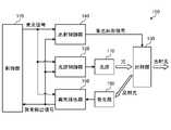
- FIG. 2is a block diagram showing a configuration example of a light emitting device according to an embodiment of the present disclosure.
- This figureis a block diagram showing a configuration example of the light emitting device 100 .
- Light emitting device 100includes light source 110 , light source control section 120 , emission section 130 , emission control section 140 , light receiving section 150 , abnormality detection section 160 and control section 170 . It should be noted that the light source control section 120, the emission section 130, the emission control section 140, the light receiving section 150, the abnormality detection section 160, and the control section 170 in FIG.
- the light source 110emits light.
- a laser diode that emits infrared lightcan be used as the light source 110 .
- the light source control unit 120controls light emission and non-light emission of the light source 110 .
- the light source control unit 120can control light emission and non-light emission of the light source 110 by outputting a control signal for a light source drive circuit (not shown) that drives the light source 110, for example.
- a light source control unit 120 in the figurecontrols the light source 110 based on the control of the control unit 170 .
- the light source control unit 120further performs processing to stop the light emission of the light source 110 when the abnormality detection unit 160 detects an abnormality. With this processing, light emission of the light source 110 can be stopped when an abnormality occurs.
- the emission part 130collects the light from the light source 110 as described above.
- the emission unit 130 shown in the figurecondenses light under the control of the emission control unit 140 .
- the output unit 130can switch between a light condensing mode and a non-condensing mode.
- the output unit 130 shown in the figurecan switch between these modes based on a control signal from the output control unit 140 .
- For the light condensing modefor example, a point-like (spot-like) light condensing mode shown in FIG. 1 can be applied. This makes it possible to irradiate light onto an object at a relatively long distance.
- the non-condensing modefor example, a mode in which light is diffused and emitted can be applied. Since the diffused light has a low energy density, even when the human body is irradiated with the diffused light, the effects can be reduced.
- the emission control section 140controls the condensing of light in the emission section 130 .
- the emission control unit 140controls condensing by outputting a control signal (condensing control signal in the figure) for controlling condensing of the emitting unit 130 .
- the emission control section 140controls the emission section 130 to the condensing mode based on the control of the control section 170 .
- the emission control section 140causes the emission section 130 to transition to the non-condensing mode. As a result, it is possible to prevent the condensed light (point-like light) from being emitted in an abnormal state.
- the control unit 170controls the light emitting device 100 as a whole.
- This control unit 170controls the light source control unit 120 by outputting a light emission signal for causing the light source 110 to emit light to the light source control unit 120 based on an instruction from a host device.
- light source control unit 120causes light source 110 to emit light.
- the control unit 170 stops outputting the light emission signalthe light source control unit 120 causes the light source 110 to stop emitting light.
- the light emission signalis also output to the emission control section 140 .
- the emission control unit 140outputs a condensing control signal to the emission unit 130 to cause the emission unit 130 to condense light.
- the emission control unit 140stops outputting the condensing control signal.
- the light emission signalis also output to the abnormality detection section 160 .
- the light receiving section 150detects light reflected by the emitting section 130 (reflected light in the same figure) from the light from the light source 110 .
- the light receiving section 150outputs a signal corresponding to the reflected light to the abnormality detecting section 160 .
- the abnormality detection section 160detects an abnormality of the light source 110 or the like based on the signal from the light receiving section 150 .
- the abnormality detection section 160outputs an abnormality detection signal to the control section 170 , the light source control section 120 and the emission control section 140 when detecting an abnormality. By outputting this abnormality detection signal, it is possible to notify the control unit 170 and the like of the detection of abnormality.
- the abnormality detection unit 160can detect, for example, a state in which the reflected light from the emission unit 130 is excessive as an abnormal state.
- the abnormality detection unit 160can detect, for example, an abnormal state when the output of the light source 110 increases more than expected and the signal of the light receiving unit 150 exceeds a predetermined threshold.
- the abnormality detection section 160can detect an abnormality when the signal from the light receiving section 150 exceeds a predetermined threshold in a state in which the control section 170 does not output the light emission signal. In this case, the cause such as breakage of the light source driving circuit of the light source 110 is assumed.
- the abnormality detection unit 160can detect the abnormal state when the signal from the light receiving unit 150 is less than a predetermined threshold value in a state where the light emission signal is output from the control unit 170 . In this case, a cause such as breakage of the emission section 130 or breakage of the light source 110 is assumed.
- the abnormality detection section 160Upon detecting such an abnormal state, the abnormality detection section 160 generates an abnormality detection signal and outputs it to the control section 170 .
- the control unit 170 to which the abnormality detection signal is inputperforms control to stop the output of the light emission signal. If the input of the abnormality detection signal continues even after the output of the light emission signal is stopped, the control unit 170 determines that the drive circuit for driving the light source 110 is damaged, and stops the power supply to the light source 110. and so on. As a result, the light emission of the light source 110 can be stopped in the event of an abnormality.
- the abnormality detection unit 160since it takes time to stop the light emission of the light source 110 via the control unit 170, the abnormality detection unit 160 also outputs the abnormality detection signal to the light source control unit 120 and the emission control unit 140 as described above.
- the light source control unit 120can stop the light emission of the light source 110 (transition to non-light emission) when an abnormality occurs, and the emission control unit 140 can stop the light collection of the emission unit 130 when an error occurs. Since these processes do not go through the control unit 170, they can be performed at high speed.
- protection capabilitycan be improved by performing double protection in the event of an abnormality in the light source control section 120 and the emission control section 140 .
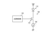
- FIG. 3is a diagram illustrating a configuration example of a light source driving circuit according to an embodiment of the present disclosure; This figure is a circuit diagram showing a configuration example of the light source drive circuit 180 .
- the light source 110 and the light source control unit 120are further illustrated in the figure.
- a power line Vdd for supplying power to the light source 110is wired to the circuit of FIG.
- the light source drive circuit 180has a MOS transistor 181 and a constant current circuit 182 .
- An n-channel MOS transistorcan be used for this MOS transistor.
- the constant current circuit 182supplies a sinking drive current to the light source 110 .
- the light source 110has an anode connected to the power line Vdd and a cathode connected to the drain of the MOS transistor 181 .
- the MOS transistor 181has a source grounded via a constant current circuit 182 and a gate connected to the output of the light source control section 120 .
- the MOS transistor 181When the ON signal from the light source control section 120 is applied to the gate of the MOS transistor 181 , the MOS transistor 181 becomes conductive and the current from the constant current circuit 182 flows through the light source 110 . Thereby, the light source 110 emits light. If the MOS transistor 181 or the constant current circuit 182 in the light source driving circuit 180 shown in FIG. Even if such an abnormal state is detected, the emission control section 140 can stop the light collection of the emission section 130 . The control unit 170 can prevent the dot-like laser beam from being emitted before the power supply to the power line Vdd is stopped.
- FIG. 4is a diagram illustrating a configuration example of an emission unit according to an embodiment of the present disclosure; This figure is a cross-sectional view showing a configuration example of the output section 130 .
- the output section 130 in the figureincludes a liquid crystal shutter 131 and a diffractive optical element 135 .
- the diffractive optical element 135converts laser light into light of a predetermined pattern by diffraction.
- the diffractive optical element 135 shown in the same figureconverts the laser light into point-like light.
- the liquid crystal shutter 131controls transmission of light from the diffractive optical element 135 .
- the liquid crystal shutter 131can adopt a configuration in which the liquid crystal portion 132 is sandwiched between transparent electrodes 133 and 134 .
- the liquid crystal of the liquid crystal section 132is oriented in a predetermined direction, the transmittance increases, and the liquid crystal becomes transparent. Thereby, the light from the diffractive optical element 135 can be transmitted.
- the orientation of the liquid crystal of the liquid crystal section 132is stopped.
- the light from the diffractive optical element 135is scattered by the liquid crystal shutter 131 and converted into diffused light. In this manner, the emission section 130 can emit condensed light according to the condensing control signal from the emission control section 140 .
- the emitted lightcan be attenuated by diffusing it.
- the configuration of the emission unit 130is not limited to this example.
- a configuration having a shutter mechanism for shielding emitted lightmay be adopted.
- the light-emitting device 100detects an abnormality in the light source 110 using the abnormality detection section 160 and outputs an abnormality detection signal. Based on this abnormality detection signal, the light source control section 120 stops the light emission of the light source 110 and the emission control section 140 stops the light collection of the emission section 130 . As a result, it is possible to prevent the condensed light from being emitted in the event of an abnormality, thereby protecting the human body and the like. By providing double protection means by the light source control section 120 and the emission control section 140, the protection capability can be improved.
- the light emitting device 100 of the above embodimentcan be applied to various products. An example in which the light emitting device 100 is applied to a distance measuring device will be described.
- FIG. 5is a diagram showing a configuration example of a distance measuring device to which the technology according to the present disclosure can be applied.
- This figureis a block diagram showing a configuration example of the distance measuring device 800 .
- Distance measuring device 800includes photodetector 813 , control device 810 , light source device 811 , and photographing lens 812 . This distance measuring device 800 performs distance measurement for measuring the distance to an object. In the figure, an object 809 is also shown.
- the light source device 811emits light.
- the light source device 811irradiates the object 809 with emitted light 801 during distance measurement.
- the light source device 811can use, for example, a light-emitting diode that emits infrared light.
- a photographing lens 812is a lens that converges light from an object 809 onto a photodetector 813 .
- the photodetector 813measures the distance to the object 809 by detecting the reflected light 802 from the object 809 .
- the photodetector 813includes a sensor that detects the reflected light 802 and a processing circuit that performs distance measurement. In this distance measurement processing, the time from the emission of the emitted light 801 by the light source device 811 to the detection of the reflected light 802 is measured, and based on the measured time from the emission of the emitted light 801 to the detection of the reflected light 802, the object is measured. 809 is the process of measuring the distance. The measured distance to the object 809 is output to an external device as distance data.
- the control device 810controls the entire distance measuring device 800 .
- the control device 810controls the light source device 811 to emit the emitted light 801 and controls the photodetector device 813 to start timing and perform distance measurement.
- the light emitting device 100 in FIG. 2can be applied to the light source device 811 in FIG.
- the light source driving devicehas an emission section 130 , a light receiving section 150 , an abnormality detection section 160 , a light source control section 120 and an emission control section 140 .
- the emission unit 130collects and emits the light from the light source 110 .
- the light receiving section 150receives light from the light source 110 via the emitting section 130 .
- the abnormality detection section 160detects an abnormality in the light emitted from the emission section 130 based on the received light.
- the light source control unit 120controls light emission of the light source 110 and stops light emission of the light source 110 when an abnormality is detected.
- the output control unit 140controls the light collection of the output unit 130 and stops the light collection of the output unit 130 when an abnormality is detected.
- the light source control section 120 and the emission control section 140can both stop the emission of the condensed light.
- the emission unit 130may stop collecting light by diffusing and emitting the light from the light source 110 . Thereby, emitted light can be attenuated.
- the abnormality detection unit 160may detect an abnormality when the amount of received light exceeds a predetermined threshold.
- the abnormality detection unit 160may detect an abnormality when the amount of received light is less than a predetermined threshold.
- control unitthat controls the light source control unit 120 and the emission control unit 140 may be further provided. As a result, it is possible to further perform processing in the event of an abnormality by the control unit.
- the light emitting device 100has a light source 110 , an emission section 130 , a light receiving section 150 , an abnormality detection section 160 , a light source control section 120 and an emission control section 140 .
- the emission unit 130collects and emits the light from the light source 110 .
- the light receiving section 150receives light from the light source 110 via the emitting section 130 .
- the abnormality detection section 160detects an abnormality in the light emitted from the emission section 130 based on the received light.
- the light source control unit 120controls light emission of the light source 110 and stops light emission of the light source 110 when an abnormality is detected.
- the output control unit 140controls the light collection of the output unit 130 and stops the light collection of the output unit 130 when an abnormality is detected.
- the light source control section 120 and the emission control section 140can both stop the emission of the condensed light.
- Distance measuring device 800includes a light emitting device having light source 110, emitting section 130, light receiving section 150, abnormality detecting section 160, light source control section 120, and emission control section 140, a sensor, and a processing circuit. It is a rangefinder with The emission unit 130 collects and emits the light from the light source 110 .
- the light receiving section 150receives light from the light source 110 via the emitting section 130 .
- the abnormality detection section 160detects an abnormality in the light emitted from the emission section 130 based on the received light.
- the light source control unit 120controls light emission of the light source 110 and stops light emission of the light source 110 when an abnormality is detected.
- the output control unit 140controls the light collection of the output unit 130 and stops the light collection of the output unit 130 when an abnormality is detected.
- the sensordetects light emitted from the light source 110 and reflected by the object.
- the processing circuitperforms processing for measuring the distance to the object based on the time from emission of light from the light source 110 to detection of reflected light.
- the light source control section 120 and the emission control section 140can both stop the emission of the condensed light.
- the present technologycan also take the following configuration.
- an emission unitthat collects and emits light from a light source; a light receiving unit that receives light from the light source via the emitting unit; an abnormality detection unit that detects an abnormality in the light emitted from the emission unit based on the received light; a light source control unit that controls light emission of the light source and stops light emission of the light source when the abnormality is detected;
- a light source driving devicecomprising: an emission control section that controls collection of light by the emission section and stops collection of light by the emission section when the abnormality is detected.
- a light sourcecomprising: an emission control section that controls collection of light by the emission section and stops collection of light by the emission section when the abnormality is detected.
- a light sourcean emission unit that collects and emits the light from the light source; a light receiving unit that receives light from the light source via the emitting unit; an abnormality detection unit that detects an abnormality in the light emitted from the emission unit based on the received light; a light source control unit that controls light emission of the light source and stops light emission of the light source when the abnormality is detected; a light-emitting device comprising: an emission control section that controls the light collection of the emission section and stops the collection of light of the emission section when the abnormality is detected; a sensor that detects light emitted from the light source and reflected by an object; and a processing circuit for measuring the distance to the object based on the time from emission of light from the light source to detection of the reflected light.
- REFERENCE SIGNS LIST100 light emitting device 110 light source 120 light source control section 130 emission section 140 emission control section 150 light receiving section 160 abnormality detection section 170 control section 800 distance measuring device 811 light source device
Landscapes
- Physics & Mathematics (AREA)
- Engineering & Computer Science (AREA)
- General Physics & Mathematics (AREA)
- Computer Networks & Wireless Communication (AREA)
- Radar, Positioning & Navigation (AREA)
- Remote Sensing (AREA)
- Electromagnetism (AREA)
- Condensed Matter Physics & Semiconductors (AREA)
- Optics & Photonics (AREA)
- Optical Radar Systems And Details Thereof (AREA)
Abstract
Description
Translated fromJapanese本開示は、光源駆動装置、発光装置及び測距装置に関する。The present disclosure relates to a light source driving device, a light emitting device, and a distance measuring device.
対象物までの距離を測定する測距装置において、対象物に光を照射して対象物からの反射光を検出し、光が対象物との間を往復する時間を計時することにより距離を測定する測距装置が使用されている。このような測距装置には、対象物に光を照射する光源が配置される。この光源は、測距範囲に応じた光量(強度)の光を照射する必要がある。比較的広い測距範囲に対応する測距装置の光源として、レーザ光を生成するレーザダイオードを発光素子として備える光源が使用されている。A distance measuring device that measures the distance to an object by irradiating the object with light, detecting the reflected light from the object, and measuring the time it takes for the light to travel back and forth between the object and the object to measure the distance. A range finder is used. A light source for irradiating an object with light is arranged in such a distance measuring device. This light source is required to irradiate light with a light amount (intensity) corresponding to the distance measurement range. 2. Description of the Related Art A light source having a laser diode for generating laser light as a light emitting element is used as a light source for a distance measuring device that supports a relatively wide distance measuring range.
エネルギー密度の高いレーザ光は人体に有害であるため、発光素子の異常を検出して発光を停止させる制御を行う光源駆動装置が提案されている(例えば、特許文献1参照)。この光源駆動装置は、レーザダイオードの光源を制御する光源制御部と光源からの光を受光する受光部とを備える。そして、この光源駆動装置は、受光部によりレーザダイオードの異常を検出した際に光源制御部における光源の発光の制御を停止させる。Since laser light with high energy density is harmful to the human body, light source driving devices have been proposed that detect an abnormality in a light-emitting element and stop light emission (for example, see Patent Document 1). This light source driving device includes a light source control section for controlling the light source of the laser diode and a light receiving section for receiving light from the light source. This light source driving device causes the light source control section to stop controlling the light emission of the light source when the light receiving section detects an abnormality in the laser diode.
しかしながら、上記の従来技術では、光源の異常時の保護が十分でないという問題がある。例えば、レーザダイオードの制御用半導体素子の破損等によりレーザダイオードに異常な電流が流れる場合等、光源制御部の制御では対応できない異常が発生した場合には、従来技術では対処できなくなる。この場合、光源駆動装置を制御するアプリケーションプロセッサ等により、レーザダイオードへの電源の供給を停止する等の処理が必要となる。しかし、この処理には時間が掛かるため、十分な保護を行うことができないという問題がある。However, the conventional technology described above has the problem that the protection in the event of an abnormality in the light source is insufficient. For example, when an abnormal current flows through the laser diode due to breakage of the control semiconductor element of the laser diode, or when an abnormality occurs that cannot be dealt with by the control of the light source control unit, the conventional technology cannot deal with it. In this case, an application processor or the like that controls the light source driver needs to perform processing such as stopping power supply to the laser diode. However, since this process takes time, there is a problem that sufficient protection cannot be provided.
そこで、本開示では、光源の異常時の保護能力を向上させる光源駆動装置、発光装置及び測距装置を提案する。Therefore, the present disclosure proposes a light source driving device, a light emitting device, and a distance measuring device that improve the protection capability in the event of an abnormality of the light source.
本開示に係る光源駆動装置は、出射部と、受光部と、異常検出部と、光源制御部と、出射制御部とを有する。出射部は、光源の光を集光して出射する。受光部は、上記出射部を介して上記光源からの光を受光する。異常検出部は、上記受光した光に基づいて上記出射部から出射される光の異常を検出する。光源制御部は、上記光源の発光を制御するとともに上記光の異常が検出される際に上記光源の発光を停止させる。出射制御部は、上記出射部の集光を制御するとともに上記光の異常が検出される際に上記出射部の集光を停止させる。A light source driving device according to the present disclosure includes an emission section, a light receiving section, an abnormality detection section, a light source control section, and an emission control section. The emitting part collects and emits the light from the light source. The light receiving section receives light from the light source via the emitting section. The abnormality detection section detects abnormality of the light emitted from the emission section based on the received light. The light source control unit controls light emission of the light source and stops light emission of the light source when abnormality of the light is detected. The emission control section controls the collection of light by the emission section and stops the collection of light by the emission section when an abnormality in the light is detected.
以下に、本開示の実施形態について図面に基づいて詳細に説明する。説明は、以下の順に行う。なお、以下の各実施形態において、同一の部位には同一の符号を付することにより重複する説明を省略する。
1.実施形態
2.測距装置への応用例Embodiments of the present disclosure will be described in detail below with reference to the drawings. The explanation is given in the following order. In addition, in each of the following embodiments, the same parts are denoted by the same reference numerals, thereby omitting redundant explanations.
1. Embodiment 2. Example of application to a rangefinder
(1.実施形態)
[発光装置の構成]
図1は、本開示の実施形態に係る発光装置の構成例を示す図である。同図は、発光装置100の構成例を表す断面図である。発光装置100は、光源110を備えて光を出射するものである。同図の発光装置100は、光源110が実装される基板102と光源110を囲繞する筐体101とを備える。この筐体101は、金属等により構成され、光源110を保護するとともに光源110からの光を遮光するものである。この筐体101の上部には出射部130が配置される。この出射部130は、光源110からの光を集光するものである。同図の矢印は、光源110から出射されて出射部130により集光される光を表したものである。同図の出射部130は、光を点状に集光して出射する例を表したものである。同図の光源110の近傍の基板102には、受光部150が更に配置される。この受光部150は、光源110の光のうち出射部130により反射された光を検出するものである。(1. Embodiment)
[Structure of Light Emitting Device]
FIG. 1 is a diagram showing a configuration example of a light emitting device according to an embodiment of the present disclosure. This figure is a cross-sectional view showing a configuration example of the
図2は、本開示の実施形態に係る発光装置の構成例を示すブロック図である。同図は、発光装置100の構成例を表すブロック図である。発光装置100は、光源110と、光源制御部120と、出射部130と、出射制御部140と、受光部150と、異常検出部160と、制御部170とを備える。なお、同図の光源制御部120、出射部130、出射制御部140、受光部150、異常検出部160及び制御部170は、請求の範囲に記載の光源駆動装置の一例である。FIG. 2 is a block diagram showing a configuration example of a light emitting device according to an embodiment of the present disclosure. This figure is a block diagram showing a configuration example of the
光源110は、光を照射するものである。この光源110には、赤外光を照射するレーザダイオードを使用することができる。The
光源制御部120は、光源110の発光及び非発光を制御するものである。この光源制御部120は、例えば、光源110を駆動する光源駆動回路(不図示)の制御信号を出力することにより、光源110の発光及び非発光を制御することができる。同図の光源制御部120は、制御部170の制御に基づいて光源110を制御する。なお、光源制御部120は、異常検出部160が異常を検出した場合に、光源110の発光を停止する処理を更に行う。この処理により、異常時に光源110の発光を停止させることができる。The light
出射部130は、前述のように光源110からの光を集光するものである。同図の出射部130は、出射制御部140の制御に基づいて光を集光する。具体的には、出射部130は、光を集光するモードと非集光のモードとを切り替えることができる。同図の出射部130は、出射制御部140からの制御信号に基づいてこのモードの切り替えを行うことができる。光の集光モードには、例えば、図1に表した点状(スポット状)に集光して出射するモードを適用することができる。これにより、比較的遠距離にある対象物に光を照射することができる。一方、非集光モードには、例えば、光を拡散させて出射するモードを適用することができる。拡散光はエネルギー密度が低くなるため、人体に照射された場合であっても影響を低減することができる。The
出射制御部140は、出射部130における光の集光を制御するものである。この出射制御部140は、出射部130の集光を制御する制御信号(同図の集光制御信号)を出力することにより、集光を制御する。出射制御部140は、制御部170の制御に基づいて出射部130を集光モードに制御する。一方、異常検出部160が異常を検出した場合には、出射制御部140は、出射部130を非集光モードに遷移させる。これにより、異常時に集光された光(点状の光)の出射を防ぐことができる。The
制御部170は、発光装置100の全体を制御するものである。この制御部170は、上位の装置からの指示に基づいて、光源制御部120に光源110を発光させる発光信号を出力することにより、光源制御部120を制御する。具体的には、制御部170から発光信号が出力されると、光源制御部120は、光源110を発光させる。制御部170からの発光信号の出力が停止されると、光源制御部120は、光源110の発光を停止する。また、発光信号は、出射制御部140にも出力される。制御部170から発光信号が出力されると、出射制御部140は、集光制御信号を出射部130に対して出力し、出射部130に光の集光を行わせる。制御部170からの発光信号の出力が停止されると、出射制御部140は、集光制御信号の出力を停止する。また、発光信号は、異常検出部160にも出力される。The
受光部150は、前述のように、光源110の光のうち出射部130により反射された光(同図の反射光)を検出するものである。この受光部150は、反射光に応じた信号を異常検出部160に対して出力する。As described above, the
異常検出部160は、受光部150からの信号に基づいて光源110等の異常を検出するものである。この異常検出部160は、異常を検出した際に異常検出信号を制御部170、光源制御部120及び出射制御部140に対して出力する。この異常検出信号の出力により、制御部170等に異常の検出を通知することができる。The
異常検出部160は、例えば、出射部130からの反射光が過剰な状態を異常状態として検出することができる。異常検出部160は、例えば、光源110の出力が想定以上に増加して受光部150の信号が所定の閾値を超える場合に異常状態として検出することができる。また、異常検出部160は、例えば、制御部170からの発光信号が出力されない状態において受光部150の信号が所定の閾値を超える場合に異常状態として検出することができる。この場合は、光源110の光源駆動回路の破損等の原因が想定される。The
また、異常検出部160は、例えば、制御部170からの発光信号が出力された状態において受光部150の信号が所定の閾値未満の場合に異常状態として検出することができる。この場合は、出射部130の破損や光源110の破損等の原因が想定される。In addition, for example, the
このような異常状態を検出すると、異常検出部160は、異常検出信号を生成して制御部170に対して出力する。この異常検出信号が入力された制御部170は、発光信号の出力を停止する制御を行う。この発光信号の出力を停止した後においても、異常検出信号の入力が続く場合には、制御部170は、光源110を駆動する駆動回路の破損と判断し、光源110への電源の供給を停止する等の処理を行う。これにより、異常時の光源110の発光を停止させることができる。Upon detecting such an abnormal state, the
しかし、制御部170を経由した光源110の発光停止の処理には時間が掛かるため、上述のように異常検出部160は、異常検出信号を光源制御部120及び出射制御部140にも出力する。これにより、異常時の光源制御部120における光源110の発光の停止(非発光への移行)処理と異常時の出射制御部140における出射部130の集光の停止処理とを行うことができる。これらの処理は、制御部170を経由しないため、高速に行うことができる。また、異常時の保護を光源制御部120及び出射制御部140において二重に行うことにより、保護能力を向上させることができる。However, since it takes time to stop the light emission of the
[光源駆動回路]
図3は、本開示の実施形態に係る光源駆動回路の構成例を示す図である。同図は、光源駆動回路180の構成例を表す回路図である。なお、同図には、光源110及び光源制御部120を更に記載した。また、同図の回路には光源110に電源を供給する電源線Vddが配線される。[Light source drive circuit]
FIG. 3 is a diagram illustrating a configuration example of a light source driving circuit according to an embodiment of the present disclosure; This figure is a circuit diagram showing a configuration example of the light
光源駆動回路180は、MOSトランジスタ181と、定電流回路182とを備える。このMOSトランジスタには、nチャネルMOSトランジスタを使用することができる。また、定電流回路182は、光源110に吸い込みの駆動電流を供給するものである。光源110のアノードは電源線Vddに接続され、カソードはMOSトランジスタ181のドレインに接続される。MOSトランジスタ181のソースは、定電流回路182を介して接地され、ゲートは光源制御部120の出力に接続される。The light
光源制御部120からのオン信号がMOSトランジスタ181のゲートに印加されると、MOSトランジスタ181が導通し、定電流回路182による電流が光源110に流れる。これにより、光源110が発光する。同図の光源駆動回路180において、MOSトランジスタ181や定電流回路182が短絡状態にて破損すると、光源110には常時電流が流れることとなる。このような異常状態が検出された場合であっても、出射制御部140において出射部130の集光を停止させることができる。制御部170により、電源線Vddへの電源の供給が停止される前に、点状のレーザ光の出射を防ぐことができる。When the ON signal from the light
[出射部130の構成]
図4は、本開示の実施形態に係る出射部の構成例を示す図である。同図は、出射部130の構成例を表す断面図である。同図の出射部130は、液晶シャッタ131と、回折光学素子135とを備える。回折光学素子135は、回折によりレーザ光を所定のパターンの光に変換するものである。同図の回折光学素子135は、レーザ光を点状の光に変換する。液晶シャッタ131は、回折光学素子135からの光の透過を制御するものである。この液晶シャッタ131は、透明電極133及び134により液晶部132を挟持する構成を採ることができる。[Configuration of output unit 130]
FIG. 4 is a diagram illustrating a configuration example of an emission unit according to an embodiment of the present disclosure; This figure is a cross-sectional view showing a configuration example of the
この透明電極133及び134に出射制御部140からの集光制御信号を印加すると、液晶部132の液晶が所定の方向に配向して透過率が上昇し、透明となる。これにより、回折光学素子135からの光を透過させることができる。一方、透明電極133及び134に出射制御部140からの集光制御信号の印加を停止すると、液晶部132の液晶の配向が停止する。これにより、回折光学素子135からの光が液晶シャッタ131により散乱されて拡散光に変換される。このように、出射部130は、出射制御部140からの集光制御信号に応じて集光した光を出射させることができる。また、異常時には出射光を拡散することにより減衰させることができる。When a condensing control signal from the
なお、出射部130の構成は、この例に限定されない。例えば、液晶シャッタ131の代わりに出射光を遮蔽するシャッタ機構を備える構成を採ることもできる。Note that the configuration of the
このように、本開示の実施形態の発光装置100は、異常検出部160により光源110の異常を検出して異常検出信号を出力する。この異常検出信号に基づいて光源制御部120により光源110の発光が停止されるとともに出射制御部140による出射部130の光の集光が停止される。これにより、異常時における集光された光の出射を防ぐことができ、人体等を保護することができる。光源制御部120及び出射制御部140による二重の保護手段を備えることにより、保護能力を向上させることができる。In this way, the light-emitting
(2.測距装置への応用例)
上述の実施形態の発光装置100は、様々な製品へ応用することができる。発光装置100を測距装置に適用する例について説明する。(2. Example of application to a distance measuring device)
The
図5は、本開示に係る技術が適用され得る測距装置の構成例を示す図である。同図は、測距装置800の構成例を表すブロック図である。測距装置800は、光検出装置813と、制御装置810と、光源装置811と、撮影レンズ812とを備える。この測距装置800は、対象物までの距離を測定する測距を行うものである。同図には、対象物809を更に記載した。FIG. 5 is a diagram showing a configuration example of a distance measuring device to which the technology according to the present disclosure can be applied. This figure is a block diagram showing a configuration example of the
光源装置811は、光を照射するものである。この光源装置811は、測距の際に対象物809に対して出射光801を照射する。光源装置811は、例えば、赤外光を出射する発光ダイオードを使用することができる。The
撮影レンズ812は、対象物809からの光を光検出装置813に集光するレンズである。同図の撮影レンズ812は、出射光801が対象物809により反射された反射光802を光検出装置813に集光する。A photographing
光検出装置813は、対象物809からの反射光802を検出して対象物809までの距離を測定するものである。この光検出装置813は、反射光802を検出するセンサと測距処理を行う処理回路とを備える。この測距処理は、光源装置811による出射光801の出射から反射光802の検出までの時間を計時し、この計時した出射光801の出射から反射光802の検出までの時間に基づいて対象物809までの距離を測定する処理である。測定した対象物809までの距離は、距離データとして外部の装置に出力される。The
制御装置810は、測距装置800の全体を制御するものである。この制御装置810は、測距の際、光源装置811を制御して出射光801を出射させ、光検出装置813を制御して計時を開始させて測距を行わせる制御を行う。The
同図の光源装置811に、図2の発光装置100を適用することができる。The
(効果)
光源駆動装置は、出射部130と、受光部150と、異常検出部160と、光源制御部120と、出射制御部140とを有する。出射部130は、光源110の光を集光して出射する。受光部150は、出射部130を介して光源110からの光を受光する。異常検出部160は、受光した光に基づいて出射部130から出射される光の異常を検出する。光源制御部120は、光源110の発光を制御するとともに異常が検出される際に光源110の発光を停止させる。出射制御部140は、出射部130の集光を制御するとともに異常が検出される際に出射部130の集光を停止させる。これにより、異常を検出た際に、集光された光の出射を光源制御部120及び出射制御部140の2つにより停止させることができる。(effect)
The light source driving device has an
また、出射部130は、光源110の光を拡散して出射することにより集光を停止してもよい。これにより、出射光を減衰させることができる。In addition, the
また、異常検出部160は、受光した光量が所定の閾値を超える場合に異常を検出してもよい。Also, the
また、異常検出部160は、受光した光量が所定の閾値未満の場合に異常を検出してもよい。Also, the
また、光源制御部120及び出射制御部140を制御する制御部を更に有してもよい。これにより、制御部による異常時の処理を更に行うことができる。Further, a control unit that controls the light
発光装置100は、光源110と、出射部130と、受光部150と、異常検出部160と、光源制御部120と、出射制御部140とを有する。出射部130は、光源110の光を集光して出射する。受光部150は、出射部130を介して光源110からの光を受光する。異常検出部160は、受光した光に基づいて出射部130から出射される光の異常を検出する。光源制御部120は、光源110の発光を制御するとともに異常が検出される際に光源110の発光を停止させる。出射制御部140は、出射部130の集光を制御するとともに異常が検出される際に出射部130の集光を停止させる。これにより、異常を検出た際に、集光された光の出射を光源制御部120及び出射制御部140の2つにより停止させることができる。The
測距装置800は、光源110と、出射部130と、受光部150と、異常検出部160と、光源制御部120と、出射制御部140とを有する発光装置と、センサと、処理回路とを有する測距装置である。出射部130は、光源110の光を集光して出射する。受光部150は、出射部130を介して光源110からの光を受光する。異常検出部160は、受光した光に基づいて出射部130から出射される光の異常を検出する。光源制御部120は、光源110の発光を制御するとともに異常が検出される際に光源110の発光を停止させる。出射制御部140は、出射部130の集光を制御するとともに異常が検出される際に出射部130の集光を停止させる。センサは、光源110から出射された光が対象物により反射された反射光を検出する。処理回路は、光源110の光の出射から反射光の検出までの時間に基づいて対象物までの距離を測定する処理を行う。これにより、異常を検出た際に、集光された光の出射を光源制御部120及び出射制御部140の2つにより停止させることができる。Distance measuring
なお、本明細書に記載された効果はあくまで例示であって限定されるものでは無く、また他の効果があってもよい。It should be noted that the effects described in this specification are only examples and are not limited, and other effects may also occur.
なお、本技術は以下のような構成も取ることができる。
(1)
光源の光を集光して出射する出射部と、
前記出射部を介して前記光源からの光を受光する受光部と、
前記受光した光に基づいて前記出射部から出射される光の異常を検出する異常検出部と、
前記光源の発光を制御するとともに前記異常が検出される際に前記光源の発光を停止させる光源制御部と、
前記出射部の集光を制御するとともに前記異常が検出される際に前記出射部の集光を停止させる出射制御部と
を有する光源駆動装置。
(2)
前記出射部は、光源の光を拡散して出射することにより前記集光を停止する
前記(1)に記載の光源駆動装置。
(3)
前記異常検出部は、前記受光した光量が所定の閾値を超える場合に前記異常を検出する
前記(1)又は(2)に記載の光源駆動装置。
(4)
前記異常検出部は、前記受光した光量が所定の閾値未満の場合に前記異常を検出する
前記(1)又は(2)に記載の光源駆動装置。
(5)
前記光源制御部及び前記出射制御部を制御する制御部を更に有する
前記(1)から(4)の何れかに記載の光源駆動装置。
(6)
光源と、
前記光源の光を集光して出射する出射部と、
前記出射部を介して前記光源からの光を受光する受光部と、
前記受光した光に基づいて前記出射部から出射される光の異常を検出する異常検出部と、
前記光源の発光を制御するとともに前記異常が検出される際に前記光源の発光を停止させる光源制御部と、
前記出射部の集光を制御するとともに前記異常が検出される際に前記出射部の集光を停止させる出射制御部と
を有する発光装置。
(7)
光源と、
前記光源の光を集光して出射する出射部と、
前記出射部を介して前記光源からの光を受光する受光部と、
前記受光した光に基づいて前記出射部から出射される光の異常を検出する異常検出部と、
前記光源の発光を制御するとともに前記異常が検出される際に前記光源の発光を停止させる光源制御部と、
前記出射部の集光を制御するとともに前記異常が検出される際に前記出射部の集光を停止させる出射制御部と
を備える発光装置と、
前記光源から出射された光が対象物により反射された反射光を検出するセンサと、
前記光源の光の出射から前記反射光の検出までの時間に基づいて前記対象物までの距離を測定する処理を行う処理回路と
を有する測距装置。Note that the present technology can also take the following configuration.
(1)
an emission unit that collects and emits light from a light source;
a light receiving unit that receives light from the light source via the emitting unit;
an abnormality detection unit that detects an abnormality in the light emitted from the emission unit based on the received light;
a light source control unit that controls light emission of the light source and stops light emission of the light source when the abnormality is detected;
A light source driving device comprising: an emission control section that controls collection of light by the emission section and stops collection of light by the emission section when the abnormality is detected.
(2)
The light source driving device according to (1), wherein the emitting unit diffuses and emits the light from the light source to stop the condensing.
(3)
The light source driving device according to (1) or (2), wherein the abnormality detection section detects the abnormality when the amount of received light exceeds a predetermined threshold.
(4)
The light source driving device according to (1) or (2), wherein the abnormality detection section detects the abnormality when the amount of received light is less than a predetermined threshold.
(5)
The light source driving device according to any one of (1) to (4) above, further including a control section that controls the light source control section and the emission control section.
(6)
a light source;
an emission unit that collects and emits the light from the light source;
a light receiving unit that receives light from the light source via the emitting unit;
an abnormality detection unit that detects an abnormality in the light emitted from the emission unit based on the received light;
a light source control unit that controls light emission of the light source and stops light emission of the light source when the abnormality is detected;
A light-emitting device comprising: an emission control section that controls collection of light by the emission section and stops collection of light by the emission section when the abnormality is detected.
(7)
a light source;
an emission unit that collects and emits the light from the light source;
a light receiving unit that receives light from the light source via the emitting unit;
an abnormality detection unit that detects an abnormality in the light emitted from the emission unit based on the received light;
a light source control unit that controls light emission of the light source and stops light emission of the light source when the abnormality is detected;
a light-emitting device comprising: an emission control section that controls the light collection of the emission section and stops the collection of light of the emission section when the abnormality is detected;
a sensor that detects light emitted from the light source and reflected by an object;
and a processing circuit for measuring the distance to the object based on the time from emission of light from the light source to detection of the reflected light.
100 発光装置
110 光源
120 光源制御部
130 出射部
140 出射制御部
150 受光部
160 異常検出部
170 制御部
800 測距装置
811 光源装置REFERENCE SIGNS
Claims (7)
Translated fromJapanese前記出射部を介して前記光源からの光を受光する受光部と、
前記受光した光に基づいて前記出射部から出射される光の異常を検出する異常検出部と、
前記光源の発光を制御するとともに前記光の異常が検出される際に前記光源の発光を停止させる光源制御部と、
前記出射部の集光を制御するとともに前記光の異常が検出される際に前記出射部の集光を停止させる出射制御部と
を有する光源駆動装置。an emission unit that collects and emits light from a light source;
a light receiving unit that receives light from the light source via the emitting unit;
an abnormality detection unit that detects an abnormality in the light emitted from the emission unit based on the received light;
a light source control unit that controls light emission of the light source and stops light emission of the light source when an abnormality in the light is detected;
A light source driving device comprising: an emission control section that controls collection of light by the emission section and stops collection of light by the emission section when an abnormality in the light is detected.
請求項1に記載の光源駆動装置。2. The light source driving device according to claim 1, wherein the emitting unit diffuses and emits the light from the light source, thereby stopping the light collection.
請求項1に記載の光源駆動装置。2. The light source driving device according to claim 1, wherein the abnormality detection section detects the abnormality when the amount of received light exceeds a predetermined threshold.
請求項1に記載の光源駆動装置。2. The light source driving device according to claim 1, wherein the abnormality detection section detects the abnormality when the amount of received light is less than a predetermined threshold.
請求項1に記載の光源駆動装置。2. The light source drive device according to claim 1, further comprising a control section for controlling said light source control section and said emission control section.
前記光源の光を集光して出射する出射部と、
前記出射部を介して前記光源からの光を受光する受光部と、
前記受光した光に基づいて前記出射部から出射される光の異常を検出する異常検出部と、
前記光源の発光を制御するとともに前記光の異常が検出される際に前記光源の発光を停止させる光源制御部と、
前記出射部の集光を制御するとともに前記光の異常が検出される際に前記出射部の集光を停止させる出射制御部と
を有する発光装置。a light source;
an emission unit that collects and emits the light from the light source;
a light receiving unit that receives light from the light source via the emitting unit;
an abnormality detection unit that detects an abnormality in the light emitted from the emission unit based on the received light;
a light source control unit that controls light emission of the light source and stops light emission of the light source when an abnormality in the light is detected;
A light-emitting device comprising: an emission control section that controls collection of light by the emission section and stops collection of light by the emission section when an abnormality in the light is detected.
前記光源の光を集光して出射する出射部と、
前記出射部を介して前記光源からの光を受光する受光部と、
前記受光した光に基づいて前記出射部から出射される光の異常を検出する異常検出部と、
前記光源の発光を制御するとともに前記光の異常が検出される際に前記光源の発光を停止させる光源制御部と、
前記出射部の集光を制御するとともに前記光の異常が検出される際に前記出射部の集光を停止させる出射制御部と
を備える発光装置と、
前記光源から出射された光が対象物により反射された反射光を検出するセンサと、
前記光源の光の出射から前記反射光の検出までの時間に基づいて前記対象物までの距離を測定する処理を行う処理回路と
を有する測距装置。a light source;
an emission unit that collects and emits the light from the light source;
a light receiving unit that receives light from the light source via the emitting unit;
an abnormality detection unit that detects an abnormality in the light emitted from the emission unit based on the received light;
a light source control unit that controls light emission of the light source and stops light emission of the light source when an abnormality in the light is detected;
a light-emitting device comprising: an emission control section that controls collection of light by the emission section and stops collection of light by the emission section when an abnormality in the light is detected;
a sensor that detects light emitted from the light source and reflected by an object;
and a processing circuit for measuring the distance to the object based on the time from emission of light from the light source to detection of the reflected light.
Priority Applications (1)
| Application Number | Priority Date | Filing Date | Title |
|---|---|---|---|
| US18/290,822US20250093481A1 (en) | 2021-08-05 | 2022-03-25 | Light source driving device, light emitting device, and distance measuring device |
Applications Claiming Priority (2)
| Application Number | Priority Date | Filing Date | Title |
|---|---|---|---|
| JP2021129060AJP2023023482A (en) | 2021-08-05 | 2021-08-05 | Light source driving device, light emitting device and distance measuring device |
| JP2021-129060 | 2021-08-05 |
Publications (1)
| Publication Number | Publication Date |
|---|---|
| WO2023013162A1true WO2023013162A1 (en) | 2023-02-09 |
Family
ID=85155663
Family Applications (1)
| Application Number | Title | Priority Date | Filing Date |
|---|---|---|---|
| PCT/JP2022/014728CeasedWO2023013162A1 (en) | 2021-08-05 | 2022-03-25 | Light source drive device, light emission device, and distance measurement device |
Country Status (3)
| Country | Link |
|---|---|
| US (1) | US20250093481A1 (en) |
| JP (1) | JP2023023482A (en) |
| WO (1) | WO2023013162A1 (en) |
Citations (6)
| Publication number | Priority date | Publication date | Assignee | Title |
|---|---|---|---|---|
| JP2002045329A (en)* | 2000-08-01 | 2002-02-12 | Fuji Photo Film Co Ltd | Fluorescent device displaying diagnostic image |
| JP2014093396A (en)* | 2012-11-02 | 2014-05-19 | Miyachi Technos Corp | Laser power supply device |
| JP2019204816A (en)* | 2018-05-21 | 2019-11-28 | スタンレー電気株式会社 | Light emission drive device and driving method thereof |
| WO2020059420A1 (en)* | 2018-09-21 | 2020-03-26 | ソニーセミコンダクタソリューションズ株式会社 | Light-source driving device and light emission device |
| WO2020084957A1 (en)* | 2018-10-25 | 2020-04-30 | ソニーセミコンダクタソリューションズ株式会社 | Fault detecting device, fault detecting method, program, and range finding device |
| JP2021097073A (en)* | 2019-12-13 | 2021-06-24 | パナソニックIpマネジメント株式会社 | Laser oscillator |
- 2021
- 2021-08-05JPJP2021129060Apatent/JP2023023482A/enactivePending
- 2022
- 2022-03-25WOPCT/JP2022/014728patent/WO2023013162A1/ennot_activeCeased
- 2022-03-25USUS18/290,822patent/US20250093481A1/enactivePending
Patent Citations (6)
| Publication number | Priority date | Publication date | Assignee | Title |
|---|---|---|---|---|
| JP2002045329A (en)* | 2000-08-01 | 2002-02-12 | Fuji Photo Film Co Ltd | Fluorescent device displaying diagnostic image |
| JP2014093396A (en)* | 2012-11-02 | 2014-05-19 | Miyachi Technos Corp | Laser power supply device |
| JP2019204816A (en)* | 2018-05-21 | 2019-11-28 | スタンレー電気株式会社 | Light emission drive device and driving method thereof |
| WO2020059420A1 (en)* | 2018-09-21 | 2020-03-26 | ソニーセミコンダクタソリューションズ株式会社 | Light-source driving device and light emission device |
| WO2020084957A1 (en)* | 2018-10-25 | 2020-04-30 | ソニーセミコンダクタソリューションズ株式会社 | Fault detecting device, fault detecting method, program, and range finding device |
| JP2021097073A (en)* | 2019-12-13 | 2021-06-24 | パナソニックIpマネジメント株式会社 | Laser oscillator |
Also Published As
| Publication number | Publication date |
|---|---|
| US20250093481A1 (en) | 2025-03-20 |
| JP2023023482A (en) | 2023-02-16 |
Similar Documents
| Publication | Publication Date | Title |
|---|---|---|
| RU2372822C2 (en) | Optical device for hair removal | |
| US11739890B2 (en) | System for detecting LED | |
| KR910020620A (en) | Remote control device and remote control method | |
| US20060043077A1 (en) | CO2 laser machining head with integrated monitoring device | |
| CN111051855A (en) | Water content sensor and road surface state detection device | |
| WO2023013162A1 (en) | Light source drive device, light emission device, and distance measurement device | |
| JP2010286235A (en) | Photoelectric sensor | |
| WO2015137050A1 (en) | Optical position detection system, control apparatus, position detection apparatus, control program, and distance measuring system | |
| JP7547348B2 (en) | Light emitting device and distance measuring device | |
| JP2000213931A (en) | Range finding module | |
| WO2020184695A1 (en) | Light irradiation system | |
| JP5286512B2 (en) | Laser annealing method and laser annealing apparatus | |
| JP5583221B2 (en) | Laser projector for travel mechanism measurement | |
| JP4893456B2 (en) | Position dimension measuring device | |
| JP6349743B2 (en) | Light source device and image projection device using the light source device | |
| KR20050009155A (en) | Missing die detection | |
| JP2000126880A (en) | Laser processing apparatus and laser processing method | |
| JP2006098104A (en) | Printing inspection system and laser marking device | |
| JP7620793B2 (en) | Laser processing head and laser processing device | |
| JP2000208012A (en) | Object detection sensor | |
| JPH0815414A (en) | Vehicle optical radar device | |
| WO2020010732A1 (en) | Glass cover plate, terminal, fingerprint recognition method and apparatus, and storage medium | |
| JP7620794B2 (en) | Laser processing head and laser processing device | |
| JP4799135B2 (en) | Ranging device | |
| US7884798B2 (en) | Protective mechanism for an optical input device |
Legal Events
| Date | Code | Title | Description |
|---|---|---|---|
| 121 | Ep: the epo has been informed by wipo that ep was designated in this application | Ref document number:22852591 Country of ref document:EP Kind code of ref document:A1 | |
| WWE | Wipo information: entry into national phase | Ref document number:18290822 Country of ref document:US | |
| NENP | Non-entry into the national phase | Ref country code:DE | |
| 122 | Ep: pct application non-entry in european phase | Ref document number:22852591 Country of ref document:EP Kind code of ref document:A1 | |
| WWP | Wipo information: published in national office | Ref document number:18290822 Country of ref document:US |