WO2023005792A1 - Wearable device and intelligent device - Google Patents
Wearable device and intelligent deviceDownload PDFInfo
- Publication number
- WO2023005792A1 WO2023005792A1PCT/CN2022/107050CN2022107050WWO2023005792A1WO 2023005792 A1WO2023005792 A1WO 2023005792A1CN 2022107050 WCN2022107050 WCN 2022107050WWO 2023005792 A1WO2023005792 A1WO 2023005792A1
- Authority
- WO
- WIPO (PCT)
- Prior art keywords
- transmission
- worm
- wearable device
- driving
- teeth
- Prior art date
- Legal status (The legal status is an assumption and is not a legal conclusion. Google has not performed a legal analysis and makes no representation as to the accuracy of the status listed.)
- Ceased
Links
Images


Classifications
- F—MECHANICAL ENGINEERING; LIGHTING; HEATING; WEAPONS; BLASTING
- F16—ENGINEERING ELEMENTS AND UNITS; GENERAL MEASURES FOR PRODUCING AND MAINTAINING EFFECTIVE FUNCTIONING OF MACHINES OR INSTALLATIONS; THERMAL INSULATION IN GENERAL
- F16M—FRAMES, CASINGS OR BEDS OF ENGINES, MACHINES OR APPARATUS, NOT SPECIFIC TO ENGINES, MACHINES OR APPARATUS PROVIDED FOR ELSEWHERE; STANDS; SUPPORTS
- F16M13/00—Other supports for positioning apparatus or articles; Means for steadying hand-held apparatus or articles
- F16M13/04—Other supports for positioning apparatus or articles; Means for steadying hand-held apparatus or articles for supporting on, or holding steady relative to, a person, e.g. by chains, e.g. rifle butt or pistol grip supports, supports attached to the chest or head
- A—HUMAN NECESSITIES
- A42—HEADWEAR
- A42B—HATS; HEAD COVERINGS
- A42B3/00—Helmets; Helmet covers ; Other protective head coverings
- A42B3/04—Parts, details or accessories of helmets
- A42B3/0406—Accessories for helmets
- A—HUMAN NECESSITIES
- A42—HEADWEAR
- A42B—HATS; HEAD COVERINGS
- A42B3/00—Helmets; Helmet covers ; Other protective head coverings
- A42B3/32—Collapsible helmets; Helmets made of separable parts ; Helmets with movable parts, e.g. adjustable
- A42B3/324—Adjustable helmets
- F—MECHANICAL ENGINEERING; LIGHTING; HEATING; WEAPONS; BLASTING
- F16—ENGINEERING ELEMENTS AND UNITS; GENERAL MEASURES FOR PRODUCING AND MAINTAINING EFFECTIVE FUNCTIONING OF MACHINES OR INSTALLATIONS; THERMAL INSULATION IN GENERAL
- F16H—GEARING
- F16H1/00—Toothed gearings for conveying rotary motion
- F16H1/02—Toothed gearings for conveying rotary motion without gears having orbital motion
- F16H1/20—Toothed gearings for conveying rotary motion without gears having orbital motion involving more than two intermeshing members
- F16H1/22—Toothed gearings for conveying rotary motion without gears having orbital motion involving more than two intermeshing members with a plurality of driving or driven shafts; with arrangements for dividing torque between two or more intermediate shafts
- F16H1/222—Toothed gearings for conveying rotary motion without gears having orbital motion involving more than two intermeshing members with a plurality of driving or driven shafts; with arrangements for dividing torque between two or more intermediate shafts with non-parallel axes
- F16H1/225—Toothed gearings for conveying rotary motion without gears having orbital motion involving more than two intermeshing members with a plurality of driving or driven shafts; with arrangements for dividing torque between two or more intermediate shafts with non-parallel axes with two or more worm and worm-wheel gearings
- G—PHYSICS
- G02—OPTICS
- G02B—OPTICAL ELEMENTS, SYSTEMS OR APPARATUS
- G02B27/00—Optical systems or apparatus not provided for by any of the groups G02B1/00 - G02B26/00, G02B30/00
- G02B27/01—Head-up displays
- G02B27/017—Head mounted
- G02B27/0176—Head mounted characterised by mechanical features
Definitions
- the inventionrelates to the technical field of smart wearable devices, in particular to a wearable device and a smart device using the wearable device.
- a wearable deviceis a portable device that is worn directly on the body or integrated into the user's clothing or accessories.
- Wearable devicesare not only a hardware device, but also achieve powerful functions through software support, data interaction, and cloud interaction. Wearable devices have brought great changes to our lives and perceptions.
- Wearable devicesmostly exist in the form of portable accessories with partial computing functions and can be connected to mobile phones and various terminals.
- the mainstream product formsinclude bracelets supported by the wrist (including watches and wristbands, etc.), Footwear (including shoes, socks or other products worn on the legs in the future), eyewear supported by the head (including glasses, helmets, headbands, etc.), as well as smart clothing, school bags, crutches, accessories and other non-mainstream Product form.
- Head-mounted wearable devicessuch as head-mounted smart glasses
- head-mounted smart glassescurrently have two main product forms, one is only including the frame and glasses legs lapped on the bridge of the nose and ears to match the human body; the other is to have The wrap-around head strap is fixed to the head.
- a manual adjustment mechanismis generally provided to adjust the tightness of the head strap, which increases the amount of operation for the user, and is not smart enough and convenient.
- the main purpose of the present inventionis to provide a wearable device and a smart device, aiming at providing a wearable device capable of automatically adjusting the tightness, so as to make the wearable device more intelligent and convenient.
- the present inventionproposes a wearable device, which includes:
- the connecting structureincludes a first connecting piece and two second connecting pieces, one end of the two second connecting pieces is connected to the main body structure, the first connecting piece is provided with an installation cavity and a communication hole
- the two communication ports of the installation cavity, each of the second connecting parts away from the end of the main structuremoves through one of the communication ports and protrudes into the installation cavity, so that the first connecting part, the two A wearing space is enclosed by the second connector and the main body structure;
- the driving structureis arranged in the installation cavity, and is respectively connected to the two second connecting parts by transmission;
- the driving structuredrives the two second connecting parts to approach or move away from the first connecting part, so as to adjust the size of the wearing space.
- each of the second connecting partsis provided with a rack at an end away from the main structure, and each of the racks moves through a communication opening and extends into the installation cavity;
- the drive structureincludes:
- the mounting frameis installed in the mounting cavity
- the driving partis arranged on the mounting frame;
- the transmission assemblyis connected to the output shaft of the drive member, and the transmission assembly is provided with teeth meshed with the rack;
- the driving memberdrives the transmission assembly to rotate, so that the two racks drive the two second connecting members to approach or move away from the first connecting member.
- the transmission assemblyincludes two worms, the driving element includes two, and the two driving elements are arranged at intervals on the mounting frame, and each of the driving elements is arranged adjacent to one of the racks , each of the worms is connected to an output shaft of the driving member, the outer wall of each of the worms is provided with the teeth, the teeth are helical teeth, and the helical teeth are along the axial direction of the worm Set in a spiral.
- the transmission assemblyincludes:
- the wormis connected to the output shaft of the driving member, the worm is provided with helical teeth, and the helical teeth are helically arranged along the axial direction of the worm;
- each of the gearsis arranged adjacent to one of the racks, and is provided with the teeth meshingly connected with the racks, and the two gears are The gear is connected with the worm drive;
- the driving memberdrives the worm and simultaneously drives the two gears to rotate, so that the two racks drive the two second connecting members to approach or move away from the first connecting member.
- the two gearsare located on opposite sides of the worm, and the two teeth are meshed with the helical teeth.
- the transmission assemblyfurther includes a coupling gear, the coupling gear is located between the two gears, and the coupling gear is provided with first transmission teeth and second transmission teeth arranged at intervals, The first transmission tooth is engaged with the helical teeth, and the second transmission tooth is engaged with the two teeth;
- the driving memberdrives the worm to drive the coupling gear to rotate
- the coupling geardrives the two gears to rotate at the same time, so that the two racks drive the two second connecting parts close to or away from the first connecting piece.
- the coupling gearincludes:
- the first transmission gearthe first transmission gear is rotatably arranged on the installation frame, the first transmission gear is provided with a mounting hole, and the periphery of the first transmission gear is provided with the first transmission teeth;
- the second transmission gear, the second transmission gearis protrudingly provided with a connection shaft, the connection shaft is passed through the installation hole, and is connected with the ripple spring, the periphery of the second transmission gear is provided with the Second drive tooth.
- first transmission gear and the second transmission gearare arranged coaxially;
- the radius of the first transmission gearis greater than the radius of the second transmission gear.
- the driving memberincludes a driving motor and a reduction box, the driving motor is arranged on the installation frame, the reduction box is connected with the driving motor, and the output shaft of the driving motor passes through the The reduction box is connected with the transmission assembly;
- the mounting frameis provided with a mounting seat, and the worm is rotatably connected to the mounting seat through a bearing.
- the present inventionalso proposes a smart device, including a terminal and the above-mentioned wearable device, where the wearable device is signal-connected to the terminal.
- the wearable device of the technical solution of the present inventionsets the connecting structure as a first connecting piece and two second connecting pieces, so that one end of the two second connecting pieces is connected to the main body structure, and the other ends of the two second connecting pieces are movably worn.
- the tightness of the spacemakes the wearable device more intelligent and convenient.
- Fig. 1is a schematic structural diagram of a wearable device in an embodiment of the present invention
- Fig. 2is a partial structural schematic diagram of the connection between the connecting structure and the driving structure in an embodiment of the present invention
- Fig. 3is a partial structural schematic diagram of the connection between the connecting structure and the driving structure in another embodiment of the present invention.
- Fig. 4is a partial structural schematic diagram of the connection between the connecting structure and the driving structure in another embodiment of the present invention.
- Fig. 5is a schematic structural view of coupling gears in an embodiment of the present invention.
- Fig. 6is a schematic cross-sectional view of a coupling gear in an embodiment of the present invention.
- Fig. 7is a structural schematic diagram of the connection between the driving member and the worm in an embodiment of the present invention.
- the meaning of "and/or” or “and/or” appearing in the whole textincludes three options, taking "A and/or B" as an example, including A option, or B option, or A and B at the same time satisfied program.
- a wearable deviceis a portable device that is worn directly on the body or integrated into the user's clothing or accessories.
- Wearable devicesare not only a hardware device, but also achieve powerful functions through software support, data interaction, and cloud interaction. Wearable devices have brought great changes to our lives and perceptions.
- Wearable devicesmostly exist in the form of portable accessories with partial computing functions and can be connected to mobile phones and various terminals.
- the mainstream product formsinclude bracelets supported by the wrist (including watches and wristbands, etc.), Footwear (including shoes, socks or other products worn on the legs in the future), eyewear supported by the head (including glasses, helmets, headbands, etc.), as well as smart clothing, school bags, crutches, accessories and other non-mainstream Product form.
- Head-mounted wearable devicessuch as head-mounted smart glasses
- head-mounted smart glassescurrently have two main product forms, one is only including the frame and glasses legs lapped on the bridge of the nose and ears to match the human body; the other is to have The wrap-around head strap is fixed to the head.
- a manual adjustment mechanismis generally provided to adjust the tightness of the head strap, which increases the amount of operation for the user, and is not smart enough and convenient.
- the wearable device 100may be eyes supported by the head, such as smart glasses, smart helmets, smart headbands, etc., which are not limited here. It can be understood that the wearable device 100 can be applied to a smart device, so that the wearable device 100 is connected with a terminal of the smart device, thereby improving user experience.
- the wearable device 100includes a main structure 1, a connecting structure 2 and a driving structure 4, wherein the connecting structure 2 includes a first connecting member 21 and two second Two connectors 22, one end of the two second connectors 22 is connected to the main body structure 1, the first connector 21 is provided with an installation cavity 211 and two communication ports 212 communicating with the installation cavity 211, each second connector 22 is far away from One end of the main structure 1 moves through a communication port 212 and extends into the installation cavity 211, so that the first connecting piece 21, the two second connecting pieces 22 and the main structure 1 are enclosed to form a wearing space 3, and the driving structure 4 is arranged on It is installed in the cavity 211 and is respectively connected to the two second connecting parts 22 in transmission; wherein, the driving structure 4 drives the two second connecting parts 22 to approach or move away from the first connecting part 21 to adjust the size of the wearing space 3 .
- the connecting structure 2includes a first connecting member 21 and two second Two connectors 22, one end of the two second connectors 22 is connected to the main body structure 1, the first connector 21 is
- the main structure 1 of the wearable device 100can be integrated with a structure of electronic components such as a motherboard, an optical machine, a microphone, a speaker, buttons, a battery, and an antenna, that is, the wearable device 100 can communicate with the smart device through the main structure 1.
- the terminalrealizes the signal connection.
- the main structure 1is also provided with a flexible pad, so that the main structure 1 contacts the body part of the user through the flexible pad, so that the flexible pad acts as a buffer.
- connection structure 2is used to connect with the main structure 1, so that the user can wear it through the connection structure 2 or the wearing space 3 formed by the connection structure 2 and the main structure 1 to facilitate wearing.
- the connection structure 2includes a first connection part 21 and two second connection parts 22, the first connection part 21 is connected between the two second connection parts 22, and the main structure 1 is connected between the two second connecting parts 22, so that the first connecting part 21, the two second connecting parts 22 and the main structure 1 enclose the wearing space 3. It can be understood that, with such arrangement, when the first connecting member 21 adjusts the two second connecting members 22 through the driving structure 4, synchronous adjustment can be realized, thereby avoiding uneven force on both sides of the main structure 1 and affecting the wearing experience of the user.
- the second connection part 22 of the connection structure 2can be fixedly connected with the main structure 1, and electronic components such as a microphone, a speaker, a button, a battery, and an antenna are arranged inside the second connection part 22 .
- the second connecting member 22 and the main body structure 1can also be set to be rotatable at a certain angle, so as to be suitable for different users.
- electronic componentssuch as batteries, speakers, buttons, batteries, antennas and the like can also be set in the first connecting piece 21, which will not be described here. Do limited.
- the first connecting part 21 and/or the second connecting part 22 of the connecting structure 2is provided with soft pads, so as to play a buffering role.
- the first connector 21is provided with an installation cavity 211 and two communication ports 212 communicating with the installation cavity 211, the drive structure 4 is arranged in the installation cavity 211, and each second connector The end of 22 away from the main structure 1 moves through a communication port 212 and extends into the installation cavity 211 , and is connected to the driving structure 4 in transmission.
- the installation cavity 211 of the first connecting member 21is used for installing and protecting the driving structure 4 , and at the same time prevents the driving structure 4 from being exposed, thereby improving the appearance of the wearable device 100 .
- the connecting port 212 of the first connecting part 21is to facilitate the flexible connection of the end of the second connecting part 22 away from the main structure 1 with the first connecting part 21, and can extend into the installation cavity 211 through the communicating port 212 to drive with the driving structure 4. connected, so as to facilitate the use of the driving structure 4 to provide a power source, so as to realize the intelligent adjustment of the wearing space 3 .
- the driving structure 4can be a driving cylinder, an automatic telescopic rod structure, a motor with a screw structure, a motor with a gear structure or a motor with a pulley structure, etc., as long as it can drive the two second connecting parts 22 close to or away from the first
- a connecting piece 21can be any structure that can adjust the size of the wearing space 3 , and is not limited here.
- connection structure 2is configured as a first connection part 21 and two second connection parts 22, so that one end of the two second connection parts 22 is connected to the main structure 1, and the two second connection parts 22 The other end of the other end moves through a communication port 212 of the first connector 21 and extends into the installation cavity 211, so that the first connector 21, the two second connectors 22 and the main structure 1 enclose the wearing space 3, and
- the driving structure 4is arranged in the installation cavity 211 of the first connecting part 21, so that the driving structure 4 is respectively connected with the transmission of the two second connecting parts 22, so that the driving structure 4 drives the two second connecting parts 22 to approach or move away from the first connecting part 22.
- the connecting piece 21is used to adjust the size of the wearing space 3 , so that the tightness of the wearing space 3 of the wearable device 100 can be automatically adjusted, making the wearable device 100 more intelligent and convenient.
- each second connecting member 22is provided with a rack 221 at an end away from the main structure 1 , and each rack 221 moves through a communication opening 212 and extends into the installation cavity 211 . It can be understood that, by providing a rack 221 at the end of the second connecting member 22 away from the main structure 1, the rack 221 can move through a communication port 212 and extend into the installation cavity 211, and be connected with the driving structure 4 in transmission, so as to Convenience can simplify the connection structure, on the other hand also simplifies the driving structure 4 .
- the installation cavity 211 of the first connecting member 21is provided with a space or a track for the rack 221 to move. Do limited.
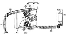
- the driving structure 4includes a mounting frame 41, a driving member 42 and a transmission assembly 43, wherein the mounting frame 41 is arranged in the mounting cavity 211, the driving member 42 is located in the mounting frame 41, and the transmission assembly 43 and The output shaft of the driving member 42 is connected, and the transmission assembly 43 is provided with teeth 4321 meshed with the rack 221; wherein, the driving member 42 drives the transmission assembly 43 to rotate, so that the two racks 221 drive the two second connecting members 22 close to or away from the first connecting piece 21 .
- the mounting frame 41is used to install and fix components such as the driver 42 and the transmission assembly 43, that is, the mounting frame 41 provides an installation basis for the components such as the driver 42 and the transmission assembly 43, and the structure of the mounting frame 41 can be installed Structures such as boards, brackets, mounting frames, or mounting seats are not limited here. It can be understood that the mounting frame 41 can be integrally formed in the mounting cavity 211 of the first connecting member 21 , so that the connection stability between the mounting frame 41 and the first connecting member 21 can be improved.
- the mounting frame 41 and the first connecting member 21are arranged separately, that is, the mounting frame 41 can be connected with the first connecting member 21 using a detachable connection structure, such as a snap connection, plug fit,
- the screw connection or pin connectionis detachably installed in the installation cavity 211 of the first connecting member 21 , which is not limited here.
- the driving member 42can be selected as a driving motor or a driving motor, and the driving member 42 is in transmission connection with the rack 221 of the second connecting member 22 through the transmission assembly 43, so that the driving rack 221 drives the second connecting member 22 through the transmission assembly 43.
- the two connecting parts 22move.
- the driving member 42includes a driving motor and a reduction box, the driving motor is arranged on the installation frame 41 , the reduction box is connected to the driving motor, and the output shaft of the driving motor is connected to the transmission assembly 43 through the reduction box.
- the transmission assembly 43may be a structure such as a transmission gear, a transmission chain, a transmission screw, or a transmission belt, which is not limited here. It can be understood that, in order to achieve stable and precise transmission, the transmission assembly 43 is provided with teeth 4321 meshing with the rack 221 .
- the transmission assembly 43includes two worms 431 , the driving member 42 includes two, and the two driving members 42 are arranged at intervals on the mounting frame 41 , and each driving member 42 is adjacent to a rack 221 Set, each worm 431 is connected with the output shaft of a driving member 42 , the outer wall of each worm 431 is provided with teeth 4321 , the teeth 4321 are helical teeth 4311 , and the helical teeth 4311 are helically arranged along the axial direction of the worm 431 .
- the transmission assembly 43is set as two worms 431.
- the driving part 42includes two, that is, the two driving parts 42 are arranged on the mounting frame 41 at intervals.
- each driver 42is arranged adjacent to a rack 221
- each worm 431is connected to the output shaft of a driver 42
- the outer wall of each worm 431is provided with teeth 4321
- the teeth 4321are helical teeth 4311
- the helical teeth 4311is arranged in a helical shape along the axial direction of the worm 431 .
- the mounting frame 41is provided with a mounting seat 411 , and the worm 431 is rotatably connected to the mounting seat 411 through a bearing. In this way, the bearing reduces the rotational friction of the worm 431 .
- the transmission assembly 43includes a worm 431 and two gears 432, wherein the worm 431 is connected to the output shaft of the driver 42, the worm 431 is provided with a helical tooth 4311, and the helical tooth 4311 is arranged in a helical shape along the axial direction of the worm 431, and two gears 432 are rotatably arranged on the mounting frame 41.
- Each gear 432is arranged adjacent to a rack 221, and is provided with a tooth 4321 meshing with the rack 221, two The gear 432 is in transmission connection with the worm 431 ; wherein, the driving member 42 drives the worm 431 to drive the two gears 432 to rotate at the same time, so that the two racks 221 drive the two second connecting parts 22 to approach or move away from the first connecting part 21 .
- the transmission assembly 43as a worm 431 and two gears 432 , only one driving member 42 is provided to drive the two second connecting members 22 to move simultaneously.
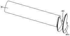
- the worm 431is connected to the output shaft of the driving member 42, and the outer peripheral wall of the worm 431 is provided with helical teeth 4311, and the helical teeth 4311 are arranged in a helical shape along the axial direction of the worm 431.
- the two gears 432are rotatably arranged on The mounting bracket 41 is connected to the two gears 432 through the helical teeth 4311 of the worm 431, so that each gear 432 is meshed with a rack 221 through the teeth 4321, so that when the worm 431 is driven by the driver 42 to rotate, the worm
- the helical tooth 4311 of 431simultaneously drives the two gears 432 to drive the two racks 221 to move.
- the helical teeth 4311can drive the two gears 432 to rotate, and at the same time, when the driving member 42 stops working, the worm 431
- the helical tooth 4311can realize self-locking to the two gears 432 .
- the two gears 432are located on opposite sides of the worm 431 , and the two teeth 4321 are meshed with the helical teeth 4311 .
- the axial direction of the worm 431is consistent with the moving direction of the two racks 221.
- the two gears 432are located on opposite sides of the worm 431, and the two gears 432 pass through the teeth 4321 and the worm 431 respectively.
- the helical teeth 4311are meshingly connected. Such an arrangement can effectively simplify the structure of the driving structure 4 .
- the transmission assembly 43further includes a coupling gear 433, the coupling gear 433 is located between the two gears 432, and the coupling gear 433 is provided with first transmission teeth arranged at intervals. 4332 and the second transmission tooth 4334, the first transmission tooth 4332 is engaged with the helical tooth 4311, and the second transmission tooth 4334 is engaged with the two teeth 4321; wherein, the driving member 42 drives the worm 431 to drive the coupling gear 433 to rotate, and The coupling gear 433 drives the two gears 432 to rotate at the same time, so that the two racks 221 drive the two second connecting parts 22 to approach or move away from the first connecting part 21 .
- the coupling gear 433is provided with first transmission teeth 4332 and second transmission teeth 4334 arranged at intervals, so that the coupling gear 433 is meshed with the helical teeth 4311 of the worm 431 through the first transmission teeth 4332, and the coupling gear 433
- the second transmission tooth 4334is meshed with the two teeth 4321 .
- the coupling gear 432includes a first transmission gear 4331 , a ripple spring 4336 and a second transmission gear 4333 , wherein the first transmission gear 4331 is rotatably mounted on the mounting frame 41 ,
- the first transmission gear 4331is provided with a mounting hole
- the periphery of the first transmission gear 4331is provided with a first transmission tooth 4332
- the ripple spring 4336is located in the mounting hole
- the second transmission gear 4333is protrudingly provided with a connecting shaft 4335
- the connecting shaft 4335passes through it. It is arranged in the mounting hole and connected with the ripple spring 4336 .
- the second transmission gear 4333is provided with a second transmission tooth 4334 on its periphery.
- the coupling gear 432is composed of a first transmission gear 4331 and a second transmission gear 4333, the periphery of the first transmission gear 4331 is provided with a first transmission tooth 4332, and the periphery of the second transmission gear 4333 is provided with a second
- the transmission gear 4334that is, the first transmission gear 4331 and the second transmission gear 4333 are connected through the connecting shaft 4335, so that the first transmission gear 4332 and the second transmission gear 4334 are spaced apart to avoid mutual interference.
- the limited torque of the driving member 42can be transmitted from the first transmission tooth 4332 to the second transmission tooth 4334 by the corrugated spring 4336, thereby pulling the second connecting member 22 through the two gears 432, In order to adjust the wearing space 3 of the wearable device 100 .
- the first transmission gear 4331 and the second transmission gear 4333are arranged coaxially. The radius of the first transmission gear 4331 is greater than the radius of the second transmission gear 4333 .
- the present inventionalso proposes a smart device, which includes a terminal and a wearable device 100, and the wearable device 100 is signal-connected to the terminal.
- the specific structure of the wearable device 100refers to the aforementioned embodiments. Since this smart device adopts all the technical solutions of the aforementioned embodiments, it at least has all the beneficial effects brought by the technical solutions of the aforementioned embodiments, and will not be described here one by one. repeat.
Landscapes
- Engineering & Computer Science (AREA)
- General Engineering & Computer Science (AREA)
- Physics & Mathematics (AREA)
- Mechanical Engineering (AREA)
- General Physics & Mathematics (AREA)
- Optics & Photonics (AREA)
- Transmission Devices (AREA)
Abstract
Description
Translated fromChinese本申请要求于2022年07月26日提交中国专利局、申请号为202110848891.6、发明名称为“穿戴设备和智能设备”的中国专利申请的优先权,其全部内容通过引用结合在本申请中。This application claims the priority of the Chinese patent application with the application number 202110848891.6 and the title of the invention "Wearable Devices and Smart Devices" filed with the China Patent Office on July 26, 2022, the entire contents of which are incorporated herein by reference.
本发明涉及智能穿戴设备技术领域,特别涉及一种穿戴设备和应用该穿戴设备的智能设备。The invention relates to the technical field of smart wearable devices, in particular to a wearable device and a smart device using the wearable device.
穿戴设备即直接穿在身上,或是整合到用户的衣服或配件的一种便携式设备。穿戴设备不仅仅是一种硬件设备,更是通过软件支持以及数据交互、云端交互来实现强大的功能,穿戴设备对我们的生活、感知带来了很大的转变。A wearable device is a portable device that is worn directly on the body or integrated into the user's clothing or accessories. Wearable devices are not only a hardware device, but also achieve powerful functions through software support, data interaction, and cloud interaction. Wearable devices have brought great changes to our lives and perceptions.
穿戴设备多以具备部分计算功能、可连接手机及各类终端的便携式配件形式存在,主流的产品形态包括以手腕为支撑的手环类(包括手表和腕带等产品),以脚为支撑的鞋类(包括鞋、袜子或者将来的其他腿上佩戴产品),以头部为支撑的眼睛类(包括眼镜、头盔、头带等),以及智能服装、书包、拐杖、配饰等各类非主流产品形态。Wearable devices mostly exist in the form of portable accessories with partial computing functions and can be connected to mobile phones and various terminals. The mainstream product forms include bracelets supported by the wrist (including watches and wristbands, etc.), Footwear (including shoes, socks or other products worn on the legs in the future), eyewear supported by the head (including glasses, helmets, headbands, etc.), as well as smart clothing, school bags, crutches, accessories and other non-mainstream Product form.
头戴式穿戴设备,例如头戴式智能眼镜等,目前的主要产品形态有两种,一种是只包括镜框和眼镜腿搭接在鼻梁和耳朵上与人体相配合;另一种是以具有环绕式包住头部的绑带形式与头部固定。相关技术中,为了适应不同人的头部形态,一般设有手动调节机构以调节头部绑带的松紧,导致增加了用户的操作量,且不够智能和便捷。Head-mounted wearable devices, such as head-mounted smart glasses, currently have two main product forms, one is only including the frame and glasses legs lapped on the bridge of the nose and ears to match the human body; the other is to have The wrap-around head strap is fixed to the head. In related technologies, in order to adapt to the head shape of different people, a manual adjustment mechanism is generally provided to adjust the tightness of the head strap, which increases the amount of operation for the user, and is not smart enough and convenient.
发明内容Contents of the invention
本发明的主要目的是提供一种穿戴设备和智能设备,旨在提供一种能够实现自动调节松紧度的穿戴设备,使该穿戴设备更加的智能和便捷。The main purpose of the present invention is to provide a wearable device and a smart device, aiming at providing a wearable device capable of automatically adjusting the tightness, so as to make the wearable device more intelligent and convenient.
为实现上述目的,本发明提出一种穿戴设备,所述穿戴设备包括:In order to achieve the above object, the present invention proposes a wearable device, which includes:
主体结构;main structure;
连接结构,所述连接结构包括第一连接件和两个第二连接件,两个所述第二连接件的一端与所述主体结构连接,所述第一连接件设有安装腔以及连通所述安装腔的两个连通口,每一所述第二连接件远离所述主体结构的一端活动穿过一所述连通口伸入所述安装腔内,以使所述第一连接件、两个所述第二连接件及所述主体结构围合形成穿戴空间;及A connecting structure, the connecting structure includes a first connecting piece and two second connecting pieces, one end of the two second connecting pieces is connected to the main body structure, the first connecting piece is provided with an installation cavity and a communication hole The two communication ports of the installation cavity, each of the second connecting parts away from the end of the main structure moves through one of the communication ports and protrudes into the installation cavity, so that the first connecting part, the two A wearing space is enclosed by the second connector and the main body structure; and
驱动结构,所述驱动结构设于所述安装腔内,并分别与两个所述第二连接件传动连接;a driving structure, the driving structure is arranged in the installation cavity, and is respectively connected to the two second connecting parts by transmission;
其中,所述驱动结构驱动两个所述第二连接件靠近或远离所述第一连接件,以调节所述穿戴空间的大小。Wherein, the driving structure drives the two second connecting parts to approach or move away from the first connecting part, so as to adjust the size of the wearing space.
在一实施例中,每一所述第二连接件远离所述主体结构的一端设有齿条,每一所述齿条活动穿过一所述连通口伸入所述安装腔内;In one embodiment, each of the second connecting parts is provided with a rack at an end away from the main structure, and each of the racks moves through a communication opening and extends into the installation cavity;
所述驱动结构包括:The drive structure includes:
安装架,所述安装架设于所述安装腔内;a mounting frame, the mounting frame is installed in the mounting cavity;
驱动件,所述驱动件设于所述安装架;及a driving part, the driving part is arranged on the mounting frame; and
传动组件,所述传动组件与所述驱动件的输出轴连接,所述传动组件设有与所述齿条啮合连接的齿牙;a transmission assembly, the transmission assembly is connected to the output shaft of the drive member, and the transmission assembly is provided with teeth meshed with the rack;
其中,所述驱动件驱动所述传动组件转动,以使两个所述齿条带动两个所述第二连接件靠近或远离所述第一连接件。Wherein, the driving member drives the transmission assembly to rotate, so that the two racks drive the two second connecting members to approach or move away from the first connecting member.
在一实施例中,所述传动组件包括两个蜗杆,所述驱动件包括两个,两个所述驱动件间隔设于所述安装架,每一所述驱动件邻近一所述齿条设置,每一所述蜗杆与一所述驱动件的输出轴连接,每一所述蜗杆的外壁设有所述齿牙,所述齿牙为螺旋齿,所述螺旋齿沿所述蜗杆的轴向呈螺旋状设置。In one embodiment, the transmission assembly includes two worms, the driving element includes two, and the two driving elements are arranged at intervals on the mounting frame, and each of the driving elements is arranged adjacent to one of the racks , each of the worms is connected to an output shaft of the driving member, the outer wall of each of the worms is provided with the teeth, the teeth are helical teeth, and the helical teeth are along the axial direction of the worm Set in a spiral.
在一实施例中,所述传动组件包括:In one embodiment, the transmission assembly includes:
蜗杆,所述蜗杆与所述驱动件的输出轴连接,所述蜗杆设有螺旋齿,所述螺旋齿沿所述蜗杆的轴向呈螺旋状设置;和a worm, the worm is connected to the output shaft of the driving member, the worm is provided with helical teeth, and the helical teeth are helically arranged along the axial direction of the worm; and
两个齿轮,两个所述齿轮转动设置于所述安装架,每一所述齿轮邻近一所述齿条设置,并设有与所述齿条啮合连接的所述齿牙,两个所述齿轮与所述蜗杆传动连接;Two gears, the two gears are rotatably arranged on the mounting frame, each of the gears is arranged adjacent to one of the racks, and is provided with the teeth meshingly connected with the racks, and the two gears are The gear is connected with the worm drive;
其中,所述驱动件驱动所述蜗杆同时带动两个所述齿轮转动,以使两个所述齿条带动两个所述第二连接件靠近或远离所述第一连接件。Wherein, the driving member drives the worm and simultaneously drives the two gears to rotate, so that the two racks drive the two second connecting members to approach or move away from the first connecting member.
在一实施例中,两个所述齿轮位于所述蜗杆的相对两侧,且两个所述齿牙均与所述螺旋齿啮合连接。In one embodiment, the two gears are located on opposite sides of the worm, and the two teeth are meshed with the helical teeth.
在一实施例中,所述传动组件还包括联轴齿轮,所述联轴齿轮位于两个所述齿轮之间,所述联轴齿轮设有间隔设置的第一传动齿和第二传动齿,所述第一传动齿与所述螺旋齿啮合连接,所述第二传动齿与两个所述齿牙啮合连接;In one embodiment, the transmission assembly further includes a coupling gear, the coupling gear is located between the two gears, and the coupling gear is provided with first transmission teeth and second transmission teeth arranged at intervals, The first transmission tooth is engaged with the helical teeth, and the second transmission tooth is engaged with the two teeth;
其中,所述驱动件驱动所述蜗杆带动所述联轴齿轮转动,且所述联轴齿轮同时带动两个所述齿轮转动,以使两个所述齿条带动两个所述第二连接件靠近或远离所述第一连接件。Wherein, the driving member drives the worm to drive the coupling gear to rotate, and the coupling gear drives the two gears to rotate at the same time, so that the two racks drive the two second connecting parts close to or away from the first connecting piece.
在一实施例中,所述联轴齿轮包括:In one embodiment, the coupling gear includes:
第一传动齿轮,所述第一传动齿轮转动设于所述安装架,所述第一传动齿轮设有安装孔,所述第一传动齿轮的周缘设有所述第一传动齿;The first transmission gear, the first transmission gear is rotatably arranged on the installation frame, the first transmission gear is provided with a mounting hole, and the periphery of the first transmission gear is provided with the first transmission teeth;
波纹弹簧,所述波纹弹簧设于所述安装孔内;及a corrugated spring disposed in the mounting hole; and
第二传动齿轮,所述第二传动齿轮凸设有连接轴,所述连接轴穿设于所述安装孔内,并与所述波纹弹簧连接,所述第二传动齿轮的周缘设有所述第二传动齿。The second transmission gear, the second transmission gear is protrudingly provided with a connection shaft, the connection shaft is passed through the installation hole, and is connected with the ripple spring, the periphery of the second transmission gear is provided with the Second drive tooth.
在一实施例中,所述第一传动齿轮和所述第二传动齿轮呈同轴设置;In one embodiment, the first transmission gear and the second transmission gear are arranged coaxially;
且/或,所述第一传动齿轮的半径大于所述第二传动齿轮的半径。And/or, the radius of the first transmission gear is greater than the radius of the second transmission gear.
在一实施例中,所述驱动件包括驱动马达和减速箱,所述驱动马达设于所述安装架,所述减速箱与所述驱动马达连接,所述驱动马达的输出轴穿过所述减速箱与所述传动组件连接;In one embodiment, the driving member includes a driving motor and a reduction box, the driving motor is arranged on the installation frame, the reduction box is connected with the driving motor, and the output shaft of the driving motor passes through the The reduction box is connected with the transmission assembly;
且/或,所述安装架设有安装座,所述蜗杆通过轴承与所述安装座转动连接。And/or, the mounting frame is provided with a mounting seat, and the worm is rotatably connected to the mounting seat through a bearing.
本发明还提出一种智能设备,包括终端和上述所述的穿戴设备,所述穿戴设备与所述终端信号连接。The present invention also proposes a smart device, including a terminal and the above-mentioned wearable device, where the wearable device is signal-connected to the terminal.
本发明技术方案的穿戴设备通过将连接结构设置为第一连接件和两个第二连接件,使得两个第二连接件的一端与主体结构连接,两个第二连接件的另一端活动穿过第一连接件的一连通口伸入安装腔内,以使第一连接件、两个第二连接件及主体结构围合形成穿戴空间,并在第一连接件的安装腔内设置驱动结构,使得驱动结构分别与两个第二连接件传动连接,从而利用驱动结构驱动两个第二连接件靠近或远离第一连接件,以调节穿戴空间的大小,如此能够实现自动调节穿戴设备的穿戴空间的松紧度,使该穿戴设备更加的智能和便捷。The wearable device of the technical solution of the present invention sets the connecting structure as a first connecting piece and two second connecting pieces, so that one end of the two second connecting pieces is connected to the main body structure, and the other ends of the two second connecting pieces are movably worn. Extend into the installation cavity through a communication port of the first connector, so that the first connector, the two second connectors and the main structure enclose to form a wearing space, and set the driving structure in the installation cavity of the first connector , so that the driving structure is respectively connected to the two second connecting parts, so that the driving structure drives the two second connecting parts close to or away from the first connecting part to adjust the size of the wearing space, so that the wearing of the wearable device can be automatically adjusted The tightness of the space makes the wearable device more intelligent and convenient.
为了更清楚地说明本发明实施例或现有技术中的技术方案,下面将对实施例或现有技术描述中所需要使用的附图作简单地介绍,显而易见地,下面描述中的附图仅仅是本发明的一些实施例,对于本领域普通技术人员来讲,在不付出创造性劳动的前提下,还可以根据这些附图示出的结构获得其他的附图。In order to more clearly illustrate the technical solutions in the embodiments of the present invention or the prior art, the following will briefly introduce the drawings that need to be used in the description of the embodiments or the prior art. Obviously, the accompanying drawings in the following description are only These are some embodiments of the present invention. For those skilled in the art, other drawings can also be obtained according to the structures shown in these drawings without creative effort.
图1为本发明一实施例中穿戴设备的结构示意图;Fig. 1 is a schematic structural diagram of a wearable device in an embodiment of the present invention;
图2为本发明一实施例中连接结构与驱动结构连接的部分结构示意图;Fig. 2 is a partial structural schematic diagram of the connection between the connecting structure and the driving structure in an embodiment of the present invention;
图3为本发明另一实施例中连接结构与驱动结构连接的部分结构示意图;Fig. 3 is a partial structural schematic diagram of the connection between the connecting structure and the driving structure in another embodiment of the present invention;
图4为本发明又一实施例中连接结构与驱动结构连接的部分结构示意图;Fig. 4 is a partial structural schematic diagram of the connection between the connecting structure and the driving structure in another embodiment of the present invention;
图5为本发明一实施例中联轴齿轮的结构示意图;Fig. 5 is a schematic structural view of coupling gears in an embodiment of the present invention;
图6为本发明一实施例中联轴齿轮的剖面示意图;Fig. 6 is a schematic cross-sectional view of a coupling gear in an embodiment of the present invention;
图7为本发明一实施例中驱动件与蜗杆连接的结构示意图。Fig. 7 is a structural schematic diagram of the connection between the driving member and the worm in an embodiment of the present invention.
附图标号说明:Explanation of reference numbers:
本发明目的的实现、功能特点及优点将结合实施例,参照附图做进一步说明。The realization of the purpose of the present invention, functional characteristics and advantages will be further described in conjunction with the embodiments and with reference to the accompanying drawings.
下面将结合本发明实施例中的附图,对本发明实施例中的技术方案进行清楚、完整地描述,显然,所描述的实施例仅仅是本发明的一部分实施例,而不是全部的实施例。基于本发明中的实施例,本领域普通技术人员在没有作出创造性劳动前提下所获得的所有其他实施例,都属于本发明保护的范围。The following will clearly and completely describe the technical solutions in the embodiments of the present invention with reference to the accompanying drawings in the embodiments of the present invention. Obviously, the described embodiments are only part of the embodiments of the present invention, not all of them. Based on the embodiments of the present invention, all other embodiments obtained by persons of ordinary skill in the art without creative efforts fall within the protection scope of the present invention.
需要说明,本发明实施例中所有方向性指示(诸如上、下、左、右、前、后……)仅用于解释在某一特定姿态(如附图所示)下各部件之间的相对位置关系、运动情况等,如果该特定姿态发生改变时,则该方向性指示也相应地随之改变。It should be noted that all directional indications (such as up, down, left, right, front, back...) in the embodiments of the present invention are only used to explain the relationship between the components in a certain posture (as shown in the accompanying drawings). Relative positional relationship, movement conditions, etc., if the specific posture changes, the directional indication will also change accordingly.
同时,全文中出现的“和/或”或“且/或”的含义为,包括三个方案,以“A和/或B”为例,包括A方案,或B方案,或A和B同时满足的方案。At the same time, the meaning of "and/or" or "and/or" appearing in the whole text includes three options, taking "A and/or B" as an example, including A option, or B option, or A and B at the same time satisfied program.
另外,在本发明中如涉及“第一”、“第二”等的描述仅用于描述目的,而不能理解为指示或暗示其相对重要性或者隐含指明所指示的技术特征的数量。由此,限定有“第一”、“第二”的特征可以明示或者隐含地包括至少一个该特征。另外,各个实施例之间的技术方案可以相互结合,但是必须是以本领域普通技术人员能够实现为基础,当技术方案的结合出现相互矛盾或无法实现时应当认为这种技术方案的结合不存在,也不在本发明要求的保护范围之内。In addition, in the present invention, descriptions such as "first", "second" and so on are used for description purposes only, and should not be understood as indicating or implying their relative importance or implicitly indicating the quantity of indicated technical features. Thus, the features defined as "first" and "second" may explicitly or implicitly include at least one of these features. In addition, the technical solutions of the various embodiments can be combined with each other, but it must be based on the realization of those skilled in the art. When the combination of technical solutions is contradictory or cannot be realized, it should be considered that the combination of technical solutions does not exist , nor within the scope of protection required by the present invention.
穿戴设备即直接穿在身上,或是整合到用户的衣服或配件的一种便携式设备。穿戴设备不仅仅是一种硬件设备,更是通过软件支持以及数据交互、云端交互来实现强大的功能,穿戴设备对我们的生活、感知带来了很大的转变。A wearable device is a portable device that is worn directly on the body or integrated into the user's clothing or accessories. Wearable devices are not only a hardware device, but also achieve powerful functions through software support, data interaction, and cloud interaction. Wearable devices have brought great changes to our lives and perceptions.
穿戴设备多以具备部分计算功能、可连接手机及各类终端的便携式配件形式存在,主流的产品形态包括以手腕为支撑的手环类(包括手表和腕带等产品),以脚为支撑的鞋类(包括鞋、袜子或者将来的其他腿上佩戴产品),以头部为支撑的眼睛类(包括眼镜、头盔、头带等),以及智能服装、书包、拐杖、配饰等各类非主流产品形态。Wearable devices mostly exist in the form of portable accessories with partial computing functions and can be connected to mobile phones and various terminals. The mainstream product forms include bracelets supported by the wrist (including watches and wristbands, etc.), Footwear (including shoes, socks or other products worn on the legs in the future), eyewear supported by the head (including glasses, helmets, headbands, etc.), as well as smart clothing, school bags, crutches, accessories and other non-mainstream Product form.
头戴式穿戴设备,例如头戴式智能眼镜等,目前的主要产品形态有两种,一种是只包括镜框和眼镜腿搭接在鼻梁和耳朵上与人体相配合;另一种是以具有环绕式包住头部的绑带形式与头部固定。相关技术中,为了适应不同人的头部形态,一般设有手动调节机构以调节头部绑带的松紧,导致增加了用户的操作量,且不够智能和便捷。Head-mounted wearable devices, such as head-mounted smart glasses, currently have two main product forms, one is only including the frame and glasses legs lapped on the bridge of the nose and ears to match the human body; the other is to have The wrap-around head strap is fixed to the head. In related technologies, in order to adapt to the head shape of different people, a manual adjustment mechanism is generally provided to adjust the tightness of the head strap, which increases the amount of operation for the user, and is not smart enough and convenient.
基于上述构思和问题,本发明提出一种穿戴设备100,该穿戴设备100可以是以头部为支撑的眼睛类,例如智能眼镜、智能头盔、智能头带等,在此不做限定。可以理解的,穿戴设备100可应用于智能设备中,使得穿戴设备100与智能设备的终端连接,从而提升用户的体验。Based on the above ideas and problems, the present invention proposes a
请结合参照图1至图4所示,在本发明实施例中,该穿戴设备100包括主体结构1、连接结构2及驱动结构4,其中,连接结构2包括第一连接件21和两个第二连接件22,两个第二连接件22的一端与主体结构1连接,第一连接件21设有安装腔211以及连通安装腔211的两个连通口212,每一第二连接件22远离主体结构1的一端活动穿过一连通口212伸入安装腔211内,以使第一连接件21、两个第二连接件22及主体结构1围合形成穿戴空间3,驱动结构4设于安装腔211内,并分别与两个第二连接件22传动连接;其中,驱动结构4驱动两个第二连接件22靠近或远离第一连接件21,以调节穿戴空间3的大小。Please refer to FIG. 1 to FIG. 4, in the embodiment of the present invention, the
在本实施例中,穿戴设备100的主体结构1可以集成有主板、光机、麦克风、喇叭、按键、电池、天线等电子元器件的结构,也即穿戴设备100通过主体结构1与智能设备的终端实现信号连接。可以理解的,为了使得用户佩戴该穿戴设备100时更加舒服,主体结构1还设有柔性垫,使得主体结构1通过柔性垫与用户的身体部分接触,从而利用柔性垫起到缓冲作用。In this embodiment, the main structure 1 of the
可以理解的,连接结构2用于与主体结构1连接,使得用户通过连接结构2实现佩戴或者通过连接结构2与主体结构1围合形成的穿戴空间3,以方便实现穿戴。It can be understood that the connection structure 2 is used to connect with the main structure 1, so that the user can wear it through the connection structure 2 or the wearing
如图1所示,在本实施例中,连接结构2包括第一连接件21和两个第二连接件22,第一连接件21连接于两个第二连接件22之间,且主体结构1连接于两个第二连接件22之间,如此使得第一连接件21、两个第二连接件22及主体结构1围合形成穿戴空间3。可以理解的,如此设置,使得第一连接件21通过驱动结构4调节两个第二连接件22时,能够实现同步调节,从而避免主体结构1两边受力不均匀,影响用户的穿戴体验。As shown in Figure 1, in this embodiment, the connection structure 2 includes a
可以理解的,连接结构2的第二连接件22与主体结构1可采用固定连接,并在第二连接件22内部设置麦克风、喇叭、按键、电池、天线等电子元器件。当然,也可将第二连接件22与主体结构1设置为可转动一定角度,从而适用于不同的用户。通过将第一连接件21与第二连接件22设置为活动连接,从而实 现伸缩活动,也可在第一连接件21内设置电池、喇叭、按键、电池、天线等电子元器件,在此不做限定。为了对用户佩戴时起到保护作用,连接结构2的第一连接件21和/或第二连接件22上设置有软垫,从而起到缓冲作用。It can be understood that the
在本实施例中,如图2所示,第一连接件21设有安装腔211以及连通安装腔211的两个连通口212,驱动结构4设于安装腔211内,每一第二连接件22远离主体结构1的一端活动穿过一连通口212伸入安装腔211内,并与驱动结构4传动连接。可以理解的,第一连接件21的安装腔211用于安装和保护驱动结构4,同时也起到避免驱动结构4外露,从而提高穿戴设备100的外观美观性。第一连接件21的连通口212是为了方便第二连接件22远离主体结构1的一端与第一连接件21活动连接,并能够穿过连通口212伸入安装腔211内与驱动结构4传动连接,从而方便利用驱动结构4提供动力源,以实现穿戴空间3的智能调节。In this embodiment, as shown in FIG. 2 , the
可以理解的,驱动结构4可以是驱动气缸、自动伸缩杆结构、电机配合丝杆结构、电机配合齿轮结构或电机配合皮带轮结构等,只要是能够实现驱动两个第二连接件22靠近或远离第一连接件21,以调节穿戴空间3的大小的结构均可,在此不做限定。It can be understood that the driving structure 4 can be a driving cylinder, an automatic telescopic rod structure, a motor with a screw structure, a motor with a gear structure or a motor with a pulley structure, etc., as long as it can drive the two second connecting
本发明的穿戴设备100通过将连接结构2设置为第一连接件21和两个第二连接件22,使得两个第二连接件22的一端与主体结构1连接,两个第二连接件22的另一端活动穿过第一连接件21的一连通口212伸入安装腔211内,以使第一连接件21、两个第二连接件22及主体结构1围合形成穿戴空间3,并在第一连接件21的安装腔211内设置驱动结构4,使得驱动结构4分别与两个第二连接件22传动连接,从而利用驱动结构4驱动两个第二连接件22靠近或远离第一连接件21,以调节穿戴空间3的大小,如此能够实现自动调节穿戴设备100的穿戴空间3的松紧度,使该穿戴设备100更加的智能和便捷。In the
在一实施例中,每一第二连接件22远离主体结构1的一端设有齿条221,每一齿条221活动穿过一连通口212伸入安装腔211内。可以理解的,通过在第二连接件22远离主体结构1的一端设有齿条221,使得齿条221活动穿过一连通口212伸入安装腔211内,并与驱动结构4传动连接,以方便可简化连接结构,另一方面也简化了驱动结构4。In one embodiment, each second connecting
在本实施例中,为了使得驱动结构4能够驱动齿条221带动第二连接件22 移动,第一连接件21的安装腔211内设置有为齿条221提供移动的空间或轨道,在此不做限定。In this embodiment, in order to enable the driving structure 4 to drive the
如图2至图4所示,驱动结构4包括安装架41、驱动件42及传动组件43,其中,安装架41设于安装腔211内,驱动件42设于安装架41,传动组件43与驱动件42的输出轴连接,传动组件43设有与齿条221啮合连接的齿牙4321;其中,驱动件42驱动传动组件43转动,以使两个齿条221带动两个第二连接件22靠近或远离第一连接件21。As shown in Figures 2 to 4, the driving structure 4 includes a mounting
在本实施例中,安装架41用于安装固定驱动件42及传动组件43等部件,也即安装架41为驱动件42及传动组件43等部件提供安装基础,安装架41的结构可以是安装板、支架、安装框或安装座等结构,在此不做限定。可以理解的,安装架41可一体成型于第一连接件21的安装腔211内,如此可提高安装架41与第一连接件21的连接稳定性。当然,为了方便实现拆装,安装架41与第一连接件21呈分体设置,也即安装架41可采用可拆卸连接结构与第一连接件21,例如采用卡扣连接、插接配合、螺钉连接或销钉连接等方式可拆卸地装设于第一连接件21的安装腔211内,在此不做限定。In this embodiment, the mounting
可以理解的,驱动件42可选为驱动电机或驱动马达等结构,驱动件42通过传动组件43与第二连接件22的齿条221传动连接,从而通过传动组件43实现驱动齿条221带动第二连接件22移动。可选地,驱动件42包括驱动马达和减速箱,驱动马达设于安装架41,减速箱与驱动马达连接,驱动马达的输出轴穿过减速箱与传动组件43连接。It can be understood that the driving
在本实施例中,传动组件43可以是传动齿轮、传动链条、传动丝杆或传动皮带等结构,在此不做限定。可以理解的,为了实现稳定且精确传动,传动组件43设有与齿条221啮合连接的齿牙4321。In this embodiment, the
在一实施例中,如图2所示,传动组件43包括两个蜗杆431,驱动件42包括两个,两个驱动件42间隔设于安装架41,每一驱动件42邻近一齿条221设置,每一蜗杆431与一驱动件42的输出轴连接,每一蜗杆431的外壁设有齿牙4321,齿牙4321为螺旋齿4311,螺旋齿4311沿蜗杆431的轴向呈螺旋状设置。In one embodiment, as shown in FIG. 2 , the
在本实施例中,传动组件43设置为两个蜗杆431,为了方便实现同时驱动两个第二连接件22移动,驱动件42包括两个,也即两个驱动件42间隔设于安装架41,每一驱动件42邻近一齿条221设置,且每一蜗杆431与一驱动件42 的输出轴连接,每一蜗杆431的外壁设有齿牙4321,齿牙4321为螺旋齿4311,螺旋齿4311沿蜗杆431的轴向呈螺旋状设置。In this embodiment, the
可以理解的,如图2至图4所示,安装架41设有安装座411,蜗杆431通过轴承与安装座411转动连接。如此设置,从而利用轴承减小蜗杆431的转动摩擦。It can be understood that, as shown in FIGS. 2 to 4 , the mounting
在一实施例中,如图3和图4所示,传动组件43包括蜗杆431和两个齿轮432,其中,蜗杆431与驱动件42的输出轴连接,蜗杆431设有螺旋齿4311,螺旋齿4311沿蜗杆431的轴向呈螺旋状设置,两个齿轮432转动设置于安装架41,每一齿轮432邻近一齿条221设置,并设有与齿条221啮合连接的齿牙4321,两个齿轮432与蜗杆431传动连接;其中,驱动件42驱动蜗杆431同时带动两个齿轮432转动,以使两个齿条221带动两个第二连接件22靠近或远离第一连接件21。In one embodiment, as shown in Figures 3 and 4, the
在本实施例中,通过将传动组件43设置为蜗杆431和两个齿轮432,使得只设置一个驱动件42即可实现同时驱动两个第二连接件22移动。可以理解的,蜗杆431与驱动件42的输出轴连接,且蜗杆431的外周壁设有螺旋齿4311,螺旋齿4311沿蜗杆431的轴向呈螺旋状设置,此时两个齿轮432转动设置于安装架41,通过蜗杆431的螺旋齿4311与两个齿轮432传动连接,从而使得每一齿轮432通过齿牙4321与一齿条221啮合连接,如此利用驱动件42驱动蜗杆431转动时,利用蜗杆431的螺旋齿4311同时驱动两个齿轮432带动两个齿条221移动。In this embodiment, by setting the
可以理解的,如图7所示,通过将蜗杆431的螺旋齿4311设置呈螺旋结构,从而使得螺旋齿4311既可以实现驱动两个齿轮432转动,同时在驱动件42停止工作时,蜗杆431的螺旋齿4311可对两个齿轮432实现自锁。It can be understood that, as shown in FIG. 7 , by setting the
在一实施例中,如图3所示,两个齿轮432位于蜗杆431的相对两侧,且两个齿牙4321均与螺旋齿4311啮合连接。可以理解的,蜗杆431的轴向方向与两个齿条221的移动方向相一致,此时两个齿轮432位于蜗杆431的相对两侧,且两个齿轮432分别通过齿牙4321与蜗杆431的螺旋齿4311啮合连接。如此设置可有效简化驱动结构4的结构。In one embodiment, as shown in FIG. 3 , the two
在一实施例中,如图4和图5所示,传动组件43还包括联轴齿轮433,联轴齿轮433位于两个齿轮432之间,联轴齿轮433设有间隔设置的第一传动齿 4332和第二传动齿4334,第一传动齿4332与螺旋齿4311啮合连接,第二传动齿4334与两个齿牙4321啮合连接;其中,驱动件42驱动蜗杆431带动联轴齿轮433转动,且联轴齿轮433同时带动两个齿轮432转动,以使两个齿条221带动两个第二连接件22靠近或远离第一连接件21。In one embodiment, as shown in FIG. 4 and FIG. 5 , the
可以理解的,通过设置联轴齿轮433,使得蜗杆431通过联轴齿轮433与两个齿轮432实现传动连接。可以理解的,联轴齿轮433设有间隔设置的第一传动齿4332和第二传动齿4334,使得联轴齿轮433通过第一传动齿4332与蜗杆431的螺旋齿4311啮合连接,联轴齿轮433通过第二传动齿4334与两个齿牙4321啮合连接。It can be understood that by setting the
在本实施例中,通过设置联轴齿轮433,使得联轴齿轮433将驱动件42和蜗杆431的驱动力传到至两个齿轮432过程中,可有效防止某些控制系统或机械故障,且驱动件42提供的扭矩过大时,有效避免两个第二连接件22移动过度,从而出现用户的头部被过度勒紧的情况,也可以保护第二连接件22不会因为动力过大而发生损坏。In this embodiment, by setting the
在一实施例中,如图4至图6所示,联轴齿轮432包括第一传动齿轮4331、波纹弹簧4336及第二传动齿轮4333,其中,第一传动齿轮4331转动设于安装架41,第一传动齿轮4331设有安装孔,第一传动齿轮4331的周缘设有第一传动齿4332,波纹弹簧4336设于安装孔内,第二传动齿轮4333凸设有连接轴4335,连接轴4335穿设于安装孔内,并与波纹弹簧4336连接,第二传动齿轮4333的周缘设有第二传动齿4334。In one embodiment, as shown in FIGS. 4 to 6 , the
在本实施例中,联轴齿轮432由第一传动齿轮4331和第二传动齿轮4333组成,第一传动齿轮4331的周缘设有第一传动齿4332,第二传动齿轮4333的周缘设有第二传动齿4334,也即第一传动齿轮4331和第二传动齿轮4333通过连接轴4335连接,以使得第一传动齿4332和第二传动齿4334间隔,从而避免相互之间发生干涉。In this embodiment, the
可以理解的,通过设置波纹弹簧4336,可利用波纹弹簧4336将驱动件42有限的扭矩从第一传动齿4332传递到第二传动齿4334上,从而通过两个齿轮432拉动第二连接件22,以实现调节穿戴设备100的穿戴空间3。如图5所示,可选地,第一传动齿轮4331和第二传动齿轮4333呈同轴设置。第一传动齿轮4331的半径大于第二传动齿轮4333的半径。It can be understood that by setting the
本发明还提出一种智能设备,该智能设备包括终端和穿戴设备100,穿戴设备100与终端信号连接。该穿戴设备100的具体结构参照前述实施例,由于本智能设备采用了前述所有实施例的全部技术方案,因此至少具有前述实施例的技术方案所带来的所有有益效果,在此不再一一赘述。The present invention also proposes a smart device, which includes a terminal and a
以上所述仅为本发明的可选实施例,并非因此限制本发明的专利范围,凡是在本发明的构思下,利用本发明说明书及附图内容所作的等效结构变换,或直接/间接运用在其他相关的技术领域均包括在本发明的专利保护范围内。The above descriptions are only optional embodiments of the present invention, and do not limit the patent scope of the present invention. Under the conception of the present invention, the equivalent structural transformation made by using the description of the present invention and the contents of the accompanying drawings, or direct/indirect use All other relevant technical fields are included in the patent protection scope of the present invention.
Claims (10)
Translated fromChineseApplications Claiming Priority (2)
| Application Number | Priority Date | Filing Date | Title |
|---|---|---|---|
| CN202110848891.6 | 2021-07-26 | ||
| CN202110848891.6ACN113566100B (en) | 2021-07-26 | 2021-07-26 | Wearing equipment and intelligent device |
Publications (1)
| Publication Number | Publication Date |
|---|---|
| WO2023005792A1true WO2023005792A1 (en) | 2023-02-02 |
Family
ID=78167796
Family Applications (1)
| Application Number | Title | Priority Date | Filing Date |
|---|---|---|---|
| PCT/CN2022/107050CeasedWO2023005792A1 (en) | 2021-07-26 | 2022-07-21 | Wearable device and intelligent device |
Country Status (2)
| Country | Link |
|---|---|
| CN (1) | CN113566100B (en) |
| WO (1) | WO2023005792A1 (en) |
Cited By (1)
| Publication number | Priority date | Publication date | Assignee | Title |
|---|---|---|---|---|
| CN119587023A (en)* | 2024-12-18 | 2025-03-11 | 江苏爱通智能科技有限公司 | A wearable device for intelligent early warning of mental health |
Families Citing this family (6)
| Publication number | Priority date | Publication date | Assignee | Title |
|---|---|---|---|---|
| CN113566100B (en)* | 2021-07-26 | 2023-08-08 | 歌尔科技有限公司 | Wearing equipment and intelligent device |
| CN116418900A (en)* | 2021-12-30 | 2023-07-11 | 华为技术有限公司 | A control method of a connection belt of a wearable device and related equipment |
| CN115437154B (en)* | 2022-09-30 | 2025-05-30 | 歌尔科技有限公司 | Head-mounted structure and head-mounted display device |
| CN115590288B (en)* | 2022-10-14 | 2025-09-26 | 歌尔股份有限公司 | Smart wearable device, smart wearable device belt structure and adjustment method thereof |
| CN116035320B (en)* | 2022-11-18 | 2025-06-27 | 赣州溢联科技有限公司 | Foldable helmet |
| CN116671716A (en)* | 2023-05-12 | 2023-09-01 | 深圳市踢踢电子有限公司 | Electric retractable belt structure and electric retractable belt backpack |
Citations (7)
| Publication number | Priority date | Publication date | Assignee | Title |
|---|---|---|---|---|
| CN108096717A (en)* | 2018-02-12 | 2018-06-01 | 柳州市红十字会医院 | A kind of helmet of laser therapy wearing |
| CN109085698A (en)* | 2017-06-14 | 2018-12-25 | 三星电子株式会社 | Head-mounted display apparatus |
| CN109149711A (en)* | 2018-09-21 | 2019-01-04 | 费先艳 | A kind of shared mobile phone charging method of automatic butt |
| CN109480806A (en)* | 2018-09-19 | 2019-03-19 | 歌尔科技有限公司 | The adjusting method of helmet and its object wearing device and helmet |
| CN208969339U (en)* | 2018-09-14 | 2019-06-11 | 北京盈迪曼德科技有限公司 | One kind wearing regulating mechanism and helmet |
| CN112083574A (en)* | 2019-06-14 | 2020-12-15 | Oppo广东移动通信有限公司 | Head band of head-mounted electronic equipment and head-mounted electronic equipment |
| CN113566100A (en)* | 2021-07-26 | 2021-10-29 | 歌尔光学科技有限公司 | Wearables and Smart Devices |
Family Cites Families (6)
| Publication number | Priority date | Publication date | Assignee | Title |
|---|---|---|---|---|
| CN102552011A (en)* | 2012-01-19 | 2012-07-11 | 陈小林 | Adjustable mechanical case and massager applying same |
| CN107729580A (en)* | 2017-12-11 | 2018-02-23 | 四川知创空间孵化器管理有限公司 | A kind of content-data supplying system for body management |
| TWI674438B (en)* | 2018-12-27 | 2019-10-11 | 廣達電腦股份有限公司 | Headset electronic device and headband adjustment structure thereof |
| TWI765197B (en)* | 2019-03-29 | 2022-05-21 | 宏達國際電子股份有限公司 | Head-mounted device and strap structure thereof |
| CN111438705A (en)* | 2020-05-14 | 2020-07-24 | 宿迁学院 | Manipulator with parallel opening and closing of claws |
| CN213069361U (en)* | 2020-10-23 | 2021-04-27 | 舜宇光学(浙江)研究院有限公司 | Adaptive adjustment device and head-mounted display equipment |
- 2021
- 2021-07-26CNCN202110848891.6Apatent/CN113566100B/enactiveActive
- 2022
- 2022-07-21WOPCT/CN2022/107050patent/WO2023005792A1/ennot_activeCeased
Patent Citations (7)
| Publication number | Priority date | Publication date | Assignee | Title |
|---|---|---|---|---|
| CN109085698A (en)* | 2017-06-14 | 2018-12-25 | 三星电子株式会社 | Head-mounted display apparatus |
| CN108096717A (en)* | 2018-02-12 | 2018-06-01 | 柳州市红十字会医院 | A kind of helmet of laser therapy wearing |
| CN208969339U (en)* | 2018-09-14 | 2019-06-11 | 北京盈迪曼德科技有限公司 | One kind wearing regulating mechanism and helmet |
| CN109480806A (en)* | 2018-09-19 | 2019-03-19 | 歌尔科技有限公司 | The adjusting method of helmet and its object wearing device and helmet |
| CN109149711A (en)* | 2018-09-21 | 2019-01-04 | 费先艳 | A kind of shared mobile phone charging method of automatic butt |
| CN112083574A (en)* | 2019-06-14 | 2020-12-15 | Oppo广东移动通信有限公司 | Head band of head-mounted electronic equipment and head-mounted electronic equipment |
| CN113566100A (en)* | 2021-07-26 | 2021-10-29 | 歌尔光学科技有限公司 | Wearables and Smart Devices |
Cited By (1)
| Publication number | Priority date | Publication date | Assignee | Title |
|---|---|---|---|---|
| CN119587023A (en)* | 2024-12-18 | 2025-03-11 | 江苏爱通智能科技有限公司 | A wearable device for intelligent early warning of mental health |
Also Published As
| Publication number | Publication date |
|---|---|
| CN113566100B (en) | 2023-08-08 |
| CN113566100A (en) | 2021-10-29 |
Similar Documents
| Publication | Publication Date | Title |
|---|---|---|
| WO2023005792A1 (en) | Wearable device and intelligent device | |
| CN113568173B (en) | Wearables and Smart Devices | |
| US11412318B2 (en) | Virtual reality head-mounted display device | |
| US9874755B2 (en) | Adjustable dual-screen head-mounted displays | |
| US10031340B2 (en) | Head mounted device | |
| TW202024722A (en) | Headset electronic device and headband adjustment structure thereof | |
| US20160366399A1 (en) | Dual-Screen Head-Mounted Displays | |
| WO2018152910A1 (en) | Video eyewear headband and video eyewear | |
| CN206193358U (en) | Bandeau system of portable virtual reality glasses | |
| CN204883056U (en) | Head-mounted display device | |
| CN108303801B (en) | Head-mounted and head-mounted electronic device | |
| CN111929904B (en) | a head-mounted device | |
| CN206470481U (en) | A kind of intelligent glasses | |
| CN210427955U (en) | Glasses shell and head-mounted display equipment | |
| CN207780370U (en) | It wears all-in-one machine and its wears regulating device | |
| CN204575982U (en) | Polytypic adaptive type mobile phone 3D glasses | |
| CN112051895A (en) | Wearable solid state computer | |
| US20190212521A1 (en) | Head-mounted electronic device and display unit thereof | |
| CN211532986U (en) | Wearable device | |
| CN213370363U (en) | Wearable device | |
| CN220795577U (en) | Intelligent head-mounted display device | |
| TWI826010B (en) | Head-mounted display | |
| CN217007862U (en) | Virtual reality equipment head that charges | |
| CN220323744U (en) | Combined type liquid crystal display module for wearing watch | |
| CN220249500U (en) | Split screen display for animation design |
Legal Events
| Date | Code | Title | Description |
|---|---|---|---|
| 121 | Ep: the epo has been informed by wipo that ep was designated in this application | Ref document number:22848397 Country of ref document:EP Kind code of ref document:A1 | |
| NENP | Non-entry into the national phase | Ref country code:DE | |
| 32PN | Ep: public notification in the ep bulletin as address of the adressee cannot be established | Free format text:NOTING OF LOSS OF RIGHTS PURSUANT TO RULE 112(1) EPC (EPO FORM 1205A DATED 10/06/2024) | |
| 122 | Ep: pct application non-entry in european phase | Ref document number:22848397 Country of ref document:EP Kind code of ref document:A1 |