WO2022264924A1 - Vacuum pump - Google Patents
Vacuum pumpDownload PDFInfo
- Publication number
- WO2022264924A1 WO2022264924A1PCT/JP2022/023381JP2022023381WWO2022264924A1WO 2022264924 A1WO2022264924 A1WO 2022264924A1JP 2022023381 WJP2022023381 WJP 2022023381WWO 2022264924 A1WO2022264924 A1WO 2022264924A1
- Authority
- WO
- WIPO (PCT)
- Prior art keywords
- rotating body
- magnetic field
- heating
- frequency
- magnetic bearing
- Prior art date
- Legal status (The legal status is an assumption and is not a legal conclusion. Google has not performed a legal analysis and makes no representation as to the accuracy of the status listed.)
- Ceased
Links
Images


Classifications
- F—MECHANICAL ENGINEERING; LIGHTING; HEATING; WEAPONS; BLASTING
- F04—POSITIVE - DISPLACEMENT MACHINES FOR LIQUIDS; PUMPS FOR LIQUIDS OR ELASTIC FLUIDS
- F04D—NON-POSITIVE-DISPLACEMENT PUMPS
- F04D19/00—Axial-flow pumps
- F04D19/02—Multi-stage pumps
- F04D19/04—Multi-stage pumps specially adapted to the production of a high vacuum, e.g. molecular pumps
- F04D19/042—Turbomolecular vacuum pumps
- F—MECHANICAL ENGINEERING; LIGHTING; HEATING; WEAPONS; BLASTING
- F04—POSITIVE - DISPLACEMENT MACHINES FOR LIQUIDS; PUMPS FOR LIQUIDS OR ELASTIC FLUIDS
- F04D—NON-POSITIVE-DISPLACEMENT PUMPS
- F04D25/00—Pumping installations or systems
- F04D25/02—Units comprising pumps and their driving means
- F04D25/06—Units comprising pumps and their driving means the pump being electrically driven
- F—MECHANICAL ENGINEERING; LIGHTING; HEATING; WEAPONS; BLASTING
- F04—POSITIVE - DISPLACEMENT MACHINES FOR LIQUIDS; PUMPS FOR LIQUIDS OR ELASTIC FLUIDS
- F04D—NON-POSITIVE-DISPLACEMENT PUMPS
- F04D27/00—Control, e.g. regulation, of pumps, pumping installations or pumping systems specially adapted for elastic fluids
- F04D27/001—Testing thereof; Determination or simulation of flow characteristics; Stall or surge detection, e.g. condition monitoring
- F—MECHANICAL ENGINEERING; LIGHTING; HEATING; WEAPONS; BLASTING
- F04—POSITIVE - DISPLACEMENT MACHINES FOR LIQUIDS; PUMPS FOR LIQUIDS OR ELASTIC FLUIDS
- F04D—NON-POSITIVE-DISPLACEMENT PUMPS
- F04D29/00—Details, component parts, or accessories
- F04D29/04—Shafts or bearings, or assemblies thereof
- F04D29/046—Bearings
- F04D29/048—Bearings magnetic; electromagnetic
- F—MECHANICAL ENGINEERING; LIGHTING; HEATING; WEAPONS; BLASTING
- F04—POSITIVE - DISPLACEMENT MACHINES FOR LIQUIDS; PUMPS FOR LIQUIDS OR ELASTIC FLUIDS
- F04D—NON-POSITIVE-DISPLACEMENT PUMPS
- F04D29/00—Details, component parts, or accessories
- F04D29/58—Cooling; Heating; Diminishing heat transfer
- F04D29/582—Cooling; Heating; Diminishing heat transfer specially adapted for elastic fluid pumps
- F04D29/584—Cooling; Heating; Diminishing heat transfer specially adapted for elastic fluid pumps cooling or heating the machine
- F—MECHANICAL ENGINEERING; LIGHTING; HEATING; WEAPONS; BLASTING
- F04—POSITIVE - DISPLACEMENT MACHINES FOR LIQUIDS; PUMPS FOR LIQUIDS OR ELASTIC FLUIDS
- F04D—NON-POSITIVE-DISPLACEMENT PUMPS
- F04D19/00—Axial-flow pumps
- F04D19/02—Multi-stage pumps
- F04D19/04—Multi-stage pumps specially adapted to the production of a high vacuum, e.g. molecular pumps
- F04D19/048—Multi-stage pumps specially adapted to the production of a high vacuum, e.g. molecular pumps comprising magnetic bearings
- F—MECHANICAL ENGINEERING; LIGHTING; HEATING; WEAPONS; BLASTING
- F05—INDEXING SCHEMES RELATING TO ENGINES OR PUMPS IN VARIOUS SUBCLASSES OF CLASSES F01-F04
- F05D—INDEXING SCHEME FOR ASPECTS RELATING TO NON-POSITIVE-DISPLACEMENT MACHINES OR ENGINES, GAS-TURBINES OR JET-PROPULSION PLANTS
- F05D2270/00—Control
- F05D2270/01—Purpose of the control system
- F05D2270/03—Purpose of the control system in variable speed operation
- F—MECHANICAL ENGINEERING; LIGHTING; HEATING; WEAPONS; BLASTING
- F05—INDEXING SCHEMES RELATING TO ENGINES OR PUMPS IN VARIOUS SUBCLASSES OF CLASSES F01-F04
- F05D—INDEXING SCHEME FOR ASPECTS RELATING TO NON-POSITIVE-DISPLACEMENT MACHINES OR ENGINES, GAS-TURBINES OR JET-PROPULSION PLANTS
- F05D2270/00—Control
- F05D2270/30—Control parameters, e.g. input parameters
- F05D2270/303—Temperature
- F05D2270/3032—Temperature excessive temperatures, e.g. caused by overheating
Definitions
- the present inventionrelates to a vacuum pump, and in particular, by heating a rotating body using an alternating magnetic field, it is possible to prevent adhesion of products even when the rotating body is stopped, and to heat the rotating body with high efficiency. It relates to a vacuum pump that can.
- a vacuum pumpis generally used to evacuate the chamber, and a turbo-molecular pump, which is one of the vacuum pumps, is often used because of its low residual gas and easy maintenance.
- the process gasmay be introduced into the chamber at a high temperature in order to increase reactivity.
- these process gasesare cooled to a certain temperature during exhaust, they become solid and may deposit products in the exhaust system.
- the process gas of this typebecomes low temperature in the turbo-molecular pump, becomes solid, and adheres and deposits inside the turbo-molecular pump.
- a heateris provided around the base of the turbomolecular pump, and the heating of this heater is controlled.
- Patent Document 1discloses a method of intersecting the rotating body with a DC magnetic field generated by a permanent magnet or an electromagnet.
- Patent Document 2discloses a method of heating a rotating body by reducing the efficiency of a motor. Furthermore, a method of heating the stator side and heating the rotating body side with the radiant heat is also conceivable.
- the present inventionhas been made in view of such conventional problems, and by heating the rotating body using an alternating magnetic field, it is possible to prevent the adhesion of products even when the rotating body is stopped, and to To provide a vacuum pump capable of heating with high efficiency.
- the present invention(claim 1) comprises a rotating body, a motor for rotationally driving the rotating body, a motor power supply for supplying power for rotating the motor, and a predetermined heating device for heating the rotating body. and a heating power supply for supplying power to the heating electromagnet by alternating current, wherein the alternating magnetic field generated by the heating electromagnet intersects the rotating body. eddy currents are generated around the intersecting AC magnetic fields in the rotating body.
- the heating electromagnetgenerates an alternating magnetic field with a predetermined magnetic field frequency by alternating current supplied from the heating power supply.
- the alternating magnetic fieldintersects the rotating body, thereby generating eddy currents around the intersecting alternating magnetic field in the rotating body. Since this eddy current causes eddy current loss, the rotating body can be heated. Since the magnetic field generated by the heating electromagnet is an alternating magnetic field, eddy current loss can be generated even when the rotation of the rotating body is stopped, and the rotating body can be heated. Deposits are expected to form even while the rotating body is stopped, so the formation of deposits can be effectively prevented. In addition, in the present invention, since eddy current loss can be directly generated in the rotating body, the rotating body can be heated with high efficiency compared to the case where the stator side is heated and the rotating body side is heated by the radiant heat. can.
- the present invention(claim 2) is characterized in that the rotating body is provided with a heating object having a predetermined conductivity to which the AC magnetic field intersects.
- the present invention(claim 3) is characterized in that the magnetic field frequency is greater than ⁇ res / ⁇ 2 when the rigid body mode natural frequency of the rotating body is defined as ⁇ res .
- the AC magnetic fieldheats the rotating body, it also generates an attractive force to the rotating body at the same time.
- This attractive forcecauses the vibration of the rotating body to increase.
- the vibration of the rotating bodycan be reduced compared to the case where the DC magnetic field with the same magnetic flux density intersects the rotating body.
- the present invention(claim 4) is characterized in that the magnetic field frequency is higher than the rated rotational frequency defined based on the mechanical angle of the rotating body.
- the spectrum of the pump vibration generated by the rotation of the rotating bodyshows a large peak of the rotation frequency component of the rotating body.
- This peak frequencyvaries depending on the operating conditions, and the maximum value is the rated rotational frequency defined based on the mechanical angle of the rotating body. Therefore, when the frequency of the alternating magnetic field generated by the heating electromagnet is higher than the rated rotational frequency defined based on the mechanical angle of the rotating body, the peak of the vibration spectrum of the pump generated by the alternating magnetic field does not coincide with the peaks in the vibrational spectrum generated by Therefore, vibration of the pump can be reduced.
- the present invention(claim 5) is characterized in that the magnetic field frequency is higher than the frequency of the current flowing through the motor at rated rotation.
- the spectrum of the pump vibration generated by the current flowing in the motorshows a large peak of the frequency component of the current flowing in the motor. This peak frequency varies depending on the operating conditions, and the maximum value is the frequency of the current flowing through the motor at rated rotation. Therefore, when the frequency of the AC magnetic field generated by the heating electromagnet is higher than the frequency of the current flowing through the motor at the rated rotation, the peak of the vibration spectrum of the pump generated by the AC magnetic field is caused by the current flowing through the motor. It does not match the peak of the vibrational spectrum. Therefore, vibration of the pump can be reduced.
- the present invention(Claim 6) comprises a motor inverter that converts the output voltage of the motor power supply and applies a voltage to the motor, and a motor inverter controller that controls the motor inverter,
- the magnetic field frequencyis more than half the control frequency of the motor inverter controller.
- the inverter for the motorcauses the alternating current to flow superimposed on the current flowing in the motor, and superimpose it on the magnetic field of the motor to generate the alternating magnetic field for heating.
- the rotating bodycan be heated by an alternating magnetic field with a higher frequency than when the rotating body is heated. Therefore, the magnetic flux density of the alternating magnetic field required to obtain the same eddy current loss of the rotating body can be reduced, the external force generated on the rotating body by the alternating magnetic field can be reduced, and the vibration of the rotating body can be reduced. can.
- the present invention(claim 7) provides a magnetic bearing that levitates and supports the rotating body in the air, a magnetic bearing power source that supplies power to the magnetic bearing, and a magnetic bearing power source that converts the output voltage of the magnetic bearing power source.
- a magnetic bearing inverterfor applying a voltage to the magnetic bearing; and a magnetic bearing inverter controller for controlling the magnetic bearing inverter, wherein the magnetic field frequency is half the control frequency of the magnetic bearing inverter controller. characterized by being greater than
- the magnetic bearing inverterIf the magnetic field frequency is greater than half of the control frequency of the magnetic bearing inverter controller, the magnetic bearing inverter superimposes an alternating current on the current flowing through the magnetic bearing, and superimposes it on the magnetic field of the magnetic bearing to supply an alternating current for heating. Compared to the case of heating a rotating body by generating a magnetic field, it can be heated by an alternating magnetic field with a higher frequency. Therefore, the magnetic flux density of the alternating magnetic field required to obtain the same eddy current loss of the rotating body can be reduced, the external force generated on the rotating body by the alternating magnetic field can be reduced, and the vibration of the rotating body can be reduced. can.
- the present invention(claim 8) comprises a magnetic bearing that levitates and supports the rotating body in the air, a magnetic bearing power supply that supplies power to the magnetic bearing, and a sensor that detects the position of the rotating body at a predetermined sensor frequency. and a demodulation circuit including a low-pass filter for demodulating the position signal, wherein the magnetic field frequency is greater than the cutoff frequency of the low-pass filter. do.
- the vibration component of the pump generated by the AC magnetic fieldwhich is included in the demodulated position signal of the displacement sensor, is reduced. Therefore, the vibration of the pump caused by the alternating magnetic field does not affect the position control of the rotating body, and more stable magnetic bearing control can be realized.
- the present invention(Claim 9) comprises a magnetic bearing that levitates and supports the rotating body in the air, a magnetic bearing power supply that supplies electric power to the magnetic bearing, and a sensor that detects the position of the rotating body at a predetermined sensor frequency. and a displacement sensor that performs non-contact measurement based on the position signal modulated by the magnetic field frequency is higher than the sensor frequency.
- the vibration component of the pump generated by the alternating magnetic fieldwhich is included in the position signal of the displacement sensor, becomes smaller. Therefore, the vibration of the pump caused by the alternating magnetic field does not affect the position control of the rotating body, and more stable magnetic bearing control can be realized.
- the present invention(claim 10) is characterized in that the heating power supply is also used as the motor power supply.
- Alternating currentis supplied to the heating electromagnet from the motor power supply. Therefore, it can be configured in a space-saving manner and at a low cost.
- the present inventioncomprises a magnetic bearing that levitates and supports the rotating body in the air, and a magnetic bearing power source that supplies power to the magnetic bearing, and the heating power source is for the magnetic bearing. It is characterized in that it is also used as a power source.
- Alternating currentis supplied to the heating electromagnet from the magnetic bearing power supply. Therefore, it can be configured in a space-saving manner and at a low cost.
- the present invention(Claim 12) is characterized in that the heating power supply is also used as the magnetic bearing power supply.
- Alternating currentis supplied to the heating electromagnet from the magnetic bearing power supply. Therefore, it can be configured in a space-saving manner and at a low cost.
- a heating electromagnet for generating an alternating magnetic field with a predetermined magnetic field frequencyis provided to heat the rotating body, and the alternating magnetic field generated by the heating electromagnet is made to intersect the rotating body.
- the alternating magnetic fieldgenerates eddy currents around the crossed alternating magnetic field in the rotating body. Since this eddy current causes eddy current loss, the rotating body can be heated. Since the magnetic field generated by the heating electromagnet is an alternating magnetic field, eddy current loss can be generated even when the rotation of the rotating body is stopped. Since deposits are expected to occur even while the pump is stopped, the formation of deposits can be effectively prevented. In addition, since eddy current loss can be generated directly in the rotating body, the rotating body can be heated with high efficiency.
- FIG. 1is a configuration diagram of a turbomolecular pump used in an embodiment of the present invention
- FIG. Configuration diagram around the power supply of the control device Diagramshowing how external force is generated by an alternating magnetic field Configuration diagram of forced vibration model Diagram showing relationship between amplitude and frequency PWM control timing chart Diagram explaining the cutoff frequency of the low-pass filter when extracting the position signal Configuration example of heating device with 4 poles
- Another configuration example of a heating device with four polesAnother configuration example of a heating device with two poles Diagram explaining how to install a heating device for a turbomolecular pump
- Example of applying a heating device to a centrifugal pump Example when heating devices are installed at multiple locations on the pumpExample of supplying alternating current by connecting heating devices in series
- Example of connecting heating devices in parallel to supply alternating currentAn example in which a heating power source is installed independently for each heating device
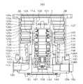
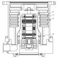
- FIG. 1shows a configuration diagram of a turbomolecular pump used in an embodiment of the present invention.
- a turbo-molecular pump 100has an intake port 101 formed at the upper end of a cylindrical outer cylinder 127 .
- a rotating body 103having a plurality of rotating blades 102 (102a, 102b, 102c, . is provided inside the outer cylinder 127.
- a rotor shaft 113is attached to the center of the rotor 103, and the rotor shaft 113 is levitated in the air and position-controlled by, for example, a 5-axis control magnetic bearing.
- the rotor 103is generally made of metal such as aluminum or aluminum alloy.
- the upper radial electromagnet 104has four electromagnets arranged in pairs on the X-axis and the Y-axis.
- Four upper radial sensors 107are provided adjacent to the upper radial electromagnets 104 and corresponding to the upper radial electromagnets 104, respectively.
- the upper radial sensor 107is, for example, an inductance sensor or an eddy current sensor having a conductive winding, and detects the position of the rotor shaft 113 based on the change in the inductance of this conductive winding, which changes according to the position of the rotor shaft 113 .
- This upper radial direction sensor 107detects the radial displacement of the rotor shaft 113, that is, the rotating body 103 fixed thereto, and sends it to a central processing unit (CPU) (not shown) inside the control device 200 shown in FIG. It is configured.
- CPUcentral processing unit
- This central processing unitis equipped with the function of a magnetic bearing controller.
- a compensation circuit having a PID control functioncontrols the upper radial electromagnet 104 based on the position signal detected by the upper radial sensor 107. is generated, and the magnetic bearing inverter 16 shown in FIG. is adjusted.
- the rotor shaft 113is made of a high magnetic permeability material (iron, stainless steel, etc.) or the like, and is attracted by the magnetic force of the upper radial electromagnet 104 . Such adjustments are made independently in the X-axis direction and the Y-axis direction.
- the lower radial electromagnet 105 and the lower radial sensor 108are arranged in the same manner as the upper radial electromagnet 104 and the upper radial sensor 107 so that the lower radial position of the rotor shaft 113 is set to the upper radial position. adjusted in the same way.
- the axial electromagnets 106A and 106Bare arranged so as to vertically sandwich a disk-shaped metal disk 111 provided below the rotor shaft 113 .
- the metal disk 111is made of a high magnetic permeability material such as iron.
- An axial sensor 109is provided to detect axial displacement of the rotor shaft 113 and its axial position signal is configured to be sent to the central processing unit (CPU) of the controller 200 .
- CPUcentral processing unit
- a compensating circuithaving, for example, a PID control function detects axial electromagnet 106A and axial electromagnet 106A based on the axial position signal detected by axial sensor 109. 106B, and the magnetic bearing inverter 16 controls the excitation of the axial electromagnets 106A and 106B based on these excitation control command signals. attracts the metal disk 111 upward by magnetic force, the axial electromagnet 106B attracts the metal disk 111 downward, and the axial position of the rotor shaft 113 is adjusted.
- control device 200appropriately adjusts the magnetic force exerted on the metal disk 111 by the axial electromagnets 106A and 106B, magnetically levitates the rotor shaft 113 in the axial direction, and holds the rotor shaft 113 in the space without contact. ing.
- the motor 121has a plurality of magnetic poles circumferentially arranged to surround the rotor shaft 113 .
- Each magnetic poleis controlled by the control device 200 so as to rotationally drive the rotor shaft 113 via an electromagnetic force acting between the magnetic poles and the rotor shaft 113 .
- the motor 121incorporates a rotation speed sensor (not shown) such as a Hall element, resolver, encoder, etc., and the rotation speed of the rotor shaft 113 is detected by the detection signal of this rotation speed sensor.
- a phase sensor(not shown) is attached, for example, near the lower radial direction sensor 108 to detect the phase of rotation of the rotor shaft 113 .
- the control device 200detects the position of the magnetic pole using both the detection signals from the phase sensor and the rotational speed sensor.
- a plurality of fixed wings 123(123a, 123b, 123c, .
- the rotor blades 102(102a, 102b, 102c, . . . ) are inclined at a predetermined angle from a plane perpendicular to the axis of the rotor shaft 113 in order to move molecules of the exhaust gas downward by collision.
- the fixed wings 123(123a, 123b, 123c, . . . ) are made of metal such as aluminum, iron, stainless steel, or copper, or metal such as an alloy containing these metals as components.
- the fixed blades 123are also inclined at a predetermined angle from a plane perpendicular to the axis of the rotor shaft 113, and are arranged inwardly of the outer cylinder 127 in a staggered manner with the stages of the rotary blades 102. ing.
- the outer peripheral end of the fixed wing 123is supported by being inserted between a plurality of stacked fixed wing spacers 125 (125a, 125b, 125c, . . . ).
- the stationary wing spacer 125is a ring-shaped member, and is made of, for example, metal such as aluminum, iron, stainless steel, or copper, or metal such as an alloy containing these metals as components.
- An outer cylinder 127is fixed to the outer circumference of the stationary blade spacer 125 with a small gap therebetween.
- a base portion 129is provided at the bottom of the outer cylinder 127 .
- An exhaust port 133is formed in the base portion 129 and communicates with the outside. Exhaust gas that has entered the intake port 101 from the chamber (vacuum chamber) side and has been transferred to the base portion 129 is sent to the exhaust port 133 .
- a threaded spacer 131is provided between the lower portion of the stationary blade spacer 125 and the base portion 129 depending on the application of the turbomolecular pump 100 .
- the threaded spacer 131is a cylindrical member made of a metal such as aluminum, copper, stainless steel, iron, or an alloy containing these metals, and has a plurality of helical thread grooves 131a on its inner peripheral surface. It is stipulated.
- the spiral direction of the thread groove 131 ais the direction in which the molecules of the exhaust gas move toward the exhaust port 133 when they move in the rotation direction of the rotor 103 .
- a cylindrical portion 102dis suspended from the lowermost portion of the rotor 103 following the rotor blades 102 (102a, 102b, 102c, . . . ).
- the outer peripheral surface of the cylindrical portion 102dis cylindrical and protrudes toward the inner peripheral surface of the threaded spacer 131, and is adjacent to the inner peripheral surface of the threaded spacer 131 with a predetermined gap therebetween.
- the exhaust gas transferred to the screw groove 131a by the rotary blade 102 and the fixed blade 123is sent to the base portion 129 while being guided by the screw groove 131a.
- the base portion 129is a disk-shaped member that constitutes the base portion of the turbomolecular pump 100, and is generally made of metal such as iron, aluminum, or stainless steel.
- the base portion 129physically holds the turbo-molecular pump 100 and also functions as a heat conduction path. Therefore, a metal having high rigidity and high thermal conductivity such as iron, aluminum, or copper is used. is desirable.
- the threaded spacer 131is arranged on the outer periphery of the cylindrical portion 102d of the rotating body 103, and the threaded groove 131a is formed on the inner peripheral surface of the threaded spacer 131.
- a thread grooveis formed on the outer peripheral surface of the cylindrical portion 102d, and a spacer having a cylindrical inner peripheral surface is arranged around it.
- the gas sucked from the intake port 101may move the upper radial electromagnet 104, the upper radial sensor 107, the motor 121, the lower radial electromagnet 105, the lower radial sensor 108, the shaft
- the electrical sectionis surrounded by a stator column 122 so as not to intrude into the electrical section composed of the directional electromagnets 106A and 106B, the axial direction sensor 109, etc., and the interior of the stator column 122 is maintained at a predetermined pressure with purge gas. It may drip.
- a pipe(not shown) is arranged in the base portion 129, and the purge gas is introduced through this pipe.
- the introduced purge gasis delivered to the exhaust port 133 through gaps between the protective bearing 120 and the rotor shaft 113 , between the rotor and stator of the motor 121 , and between the stator column 122 and the inner cylindrical portion of the rotor blade 102 .
- the turbo-molecular pump 100requires model identification and control based on individually adjusted unique parameters (eg, various characteristics corresponding to the model).
- the turbomolecular pump 100has an electronic circuit section 141 in its body.
- the electronic circuit section 141includes a semiconductor memory such as an EEP-ROM, electronic components such as semiconductor elements for accessing the same, a board 143 for mounting them, and the like.
- the electronic circuit section 141is accommodated, for example, below a rotational speed sensor (not shown) near the center of a base section 129 that constitutes the lower portion of the turbo-molecular pump 100 and is closed by an airtight bottom cover 145 .
- some of the process gases introduced into the chamberhave the property of becoming solid when their pressure exceeds a predetermined value or their temperature falls below a predetermined value. be.
- the pressure of the exhaust gasis lowest at the inlet 101 and highest at the outlet 133 .
- the process gasbecomes solid and turbo molecules are formed. It adheres and deposits inside the pump 100 .
- a solid producteg, AlCl 3
- deposits of the process gasaccumulate inside the turbo-molecular pump 100
- the depositsnarrow the pump flow path and cause the performance of the turbo-molecular pump 100 to deteriorate.
- the above-described productis likely to solidify and adhere to portions near the exhaust port 133 and near the threaded spacer 131 where the pressure is high.
- a heater(not shown) or an annular water-cooling pipe 149 is wound around the outer circumference of the base portion 129 or the like, and a temperature sensor (for example, a thermistor) (not shown) is embedded in the base portion 129, for example. Based on the signal from the temperature sensor, the heating of the heater and the cooling control by the water cooling pipe 149 are controlled (hereinafter referred to as TMS: Temperature Management System) so as to keep the temperature of the base portion 129 at a constant high temperature (set temperature). It is
- FIG. 1In FIG. 1, between the protective bearing 1 and the upper radial direction sensor 107, a two-pole heating electromagnet 3A and a two-pole heating electromagnet 3B are arranged facing each other with a rotor shaft 113 interposed therebetween.
- the heating electromagnet 3A and the heating electromagnet 3Bcorrespond to the heating device 3, and as shown in FIG. .
- the alternating currentexcites the heating electromagnet 3A and the heating electromagnet 3B to generate an alternating magnetic field.
- the generated alternating magnetic fieldintersects the rotor shaft 113 .
- Eddy currentsare generated around the crossed alternating magnetic fields.
- a non-illustrated electrically conductive object to be heatedmay be fixed to the rotor shaft 113, and an AC magnetic field may penetrate through the object to be heated to generate an eddy current.
- Materials of the object to be heatedinclude conductive metals such as iron, stainless steel, and aluminum, but ferromagnetic materials such as iron and stainless steel are more desirable.
- the rotating body 103is heated by this eddy current.
- the alternating magnetic fieldmay be a sine wave, a square wave, a triangular wave, or any other waveform, or a combination thereof. Also, a DC magnetic field may be offset from this AC magnetic field. For other waveforms, the fundamental component of each waveform is taken as the frequency of the magnetic field.
- Equation 1Eddy current loss
- the plate thickness tthe fluctuation frequency f of the magnetic field
- the eddy current loss P ecan be expressed by Equation 1 when defined as the volume V of the magnetic material subjected to fluctuation, the maximum magnetic flux density B m , and the specific resistance ⁇ of the magnetic material. [Number 1] According to Equation 1, it can be seen that the eddy current loss P e increases with the square of the frequency of the AC magnetic field.
- the heat generated due to the eddy current loss P ecan be efficiently generated in a non-contact manner. Also, it can be seen that the magnetic flux density Bm of the magnetic field required to obtain the same eddy current loss P e decreases in inverse proportion to the fluctuation frequency f of the magnetic field.
- the eddy current loss P ecan be generated even when the rotation of the rotor shaft 113 is stopped. Since deposits are expected to occur even while the pump is stopped, the formation of deposits can be effectively prevented.
- Vibration of the rotating body 103causes failure of the rotating body 103 .
- magnetic bearing controlbecomes impossible due to increased vibration of the rotating body 103, and touchdown occurs in which the rotor shaft 113 comes into contact with the protective bearings 1 and 120. There is a risk.
- the vibration of the rotating body 103is transmitted to the entire pump via the bearings, the motor 121, and the like.
- an upper radial electromagnet 104, a lower radial electromagnet 105, axial electromagnets 106A and 106B which constitute magnetic bearings, electromagnets of the motor 121, and heating electromagnets 3A and 3B of the heating device 3are provided. etc. exist.
- electromagnetswhen a current flows through a coil to generate a magnetic field, interaction between the magnetic field and the core causes deformation of the core and vibration. This vibration is transmitted to the entire pump.
- FIG. 3shows how an external force is generated by this AC magnetic field.
- FIG. 3shows the state of the magnetic field and the external force in the two-pole arrangement shown in FIGS.
- the left and right external forces F L and F Rshould ideally be balanced.
- an external forceis generated on the rotor shaft 113 due to factors such as variation in shape due to machining accuracy, eccentricity of the rotor shaft 113 due to imbalance, and variation in magnetism of the material.
- the external force F R generated when the alternating magnetic field crosses the rotor shaft 113is proportional to the square of the magnetic flux density B g of the gap between the heating electromagnet 3B and the rotor shaft 113 as shown in Equation (2).
- the external force F R in Equation 2is defined as Equation 3 using the proportionality constant K g .
- Equation 20The amplitude a of the rotor shaft 113 with respect to the DC component of the force is given by Equation (21). [number 21]
- Equation 22the amplitude of the AC component of the angular frequency ⁇ 1 of the external force is less than Equation 22
- the amplitude of the displacement of the rotor shaft 113 due to the forced vibration due to the AC magnetic fieldis the same as the maximum magnetic flux density of the AC magnetic field. is smaller than when [number 22] ⁇ 1 which becomes Equation 23 is Equation 24. Also, ⁇ 0 and ⁇ 1 have the relationship of Equation 25. [number 23] [Number 24] [number 25]
- heating electromagnets 3A and 3Bare composed of a core 6 mainly made of a laminated steel plate or ferrite, coils 4a and 4b wound around salient pole portions 7a and 7b of the core 6, and the like.
- a magnetomotive forceis generated when an alternating current supplied from a heating power supply flows through the coils 4a and 4b, and an alternating magnetic field having the same frequency as that of the alternating current is generated in the core 6.
- FIG. The generated alternating magnetic fieldintersects the rotor shaft 113 through the gap to form closed loops 5a and 5b of magnetic lines of force.
- the interaction between the alternating magnetic field and the core 6causes deformation of the core 6, and vibration of the frequency component of the alternating magnetic field is generated in the heating electromagnets 3A and 3B.
- the vibrations of the heating electromagnets 3A and 3Bare transmitted to the entire pump via the connecting portions between the heating electromagnets 3A and 3B and the pump.
- the vibration of the rotating body 103 caused by the rotation of the rotating body 103will be considered.
- an external forceis generated on the rotating body 103 due to variations in shape due to machining accuracy, eccentricity of the rotating body 103 due to imbalance, variations in magnetic properties of the material, and the like, and vibration occurs.
- a large peak of the rotation frequency component of the rotating body 103appears in the spectrum of this vibration. This peak frequency changes depending on the operating state, and the maximum value is the rated rotational frequency defined based on the mechanical angle of the rotor 103 .
- the peak of the vibration spectrum of the pump generated by the alternating magnetic fieldis It does not coincide with the vibration spectrum peak generated by the rotation of the rotating body 103 . Therefore, the peak of the vibration spectrum of the pump can be reduced.
- the motor 121is composed of a stator fixed to the pump, which is composed of an electromagnet with a core wound with a coil, and a rotor that transmits torque generated by interaction with a magnetic field generated from the stator to a rotating body. If the motor 121 is, for example, a permanent magnet synchronous motor, the frequency of the current at rated rotation is equal to the electrical angular frequency, and the electrical angular frequency can be calculated by multiplying the mechanical angular frequency by the number of pole pairs.
- the core deformationoccurs due to the interaction between the magnetic field and the core, and vibration of the frequency component of the current flowing through the motor occurs. This vibration is transmitted to the entire pump through the joint between the motor and the pump.
- PWMPulse Width Modulation
- a motor inverter 18is performed for rotational driving of the motor 121 .
- this PWM controlis controlled at a period t0 .
- the motor inverter 18causes the motor inverter 18 to supply an alternating current superimposed on the current flowing through the motor 121, causing the motor to Compared to the case of heating the rotating body 103 by generating an alternating magnetic field for heating by superimposing it on the magnetic field of 121, it is possible to heat the rotating body 103 with an alternating magnetic field of a higher frequency.
- the magnetic flux density of the alternating magnetic field required to obtain the same eddy current loss of the rotating body 103can be reduced, the external force generated on the rotating body 103 by the alternating magnetic field can be reduced, and the vibration of the rotating body 103 can be reduced. can do.
- the PWM control for controlling the magnetic bearingis also controlled at the period t0 . That is, if the rotating body 103 is heated by the alternating magnetic field at a frequency higher than twice the control frequency of the magnetic bearing inverter controller, the magnetic bearing inverter 16 causes the alternating current to flow superimposed on the current flowing through the magnetic bearing. , the rotating body 103 can be heated with an alternating magnetic field having a higher frequency than in the case of heating the rotor 103 by generating an alternating magnetic field for heating that is superimposed on the magnetic field of the magnetic bearing.
- the magnetic flux density of the alternating magnetic field required to obtain the same eddy current loss of the rotating body 103can be reduced, the external force generated on the rotating body 103 by the alternating magnetic field can be reduced, and the vibration of the rotating body 103 can be reduced. can do.
- an inductance sensor or an eddy current sensoris used for the lower radial direction sensor 108 and the upper radial direction sensor 107 .
- a modulated wave having a predetermined sensor frequencyis superimposed on the displacement signals detected by the lower radial direction sensor 108 and the upper radial direction sensor 107. Based on this modulated wave, the heating electromagnet 3A and the heating electromagnet 3A generate a heating signal.
- a suitable frequency of the AC magnetic field generated by the electromagnet 3Bis determined.
- the position signals output from the lower radial direction sensor 108 and the upper radial direction sensor 107are demodulated by a demodulation circuit 11 including a low-pass filter (LPF), and then adjusted by the magnetic bearing controller 13. , excites and drives the lower radial electromagnet 105 and the upper radial electromagnet 104 .
- LPFlow-pass filter
- the frequency of the AC magnetic field generated by the heating electromagnets 3A and 3Bis higher than the cutoff frequency of the low-pass filter (the frequency that is 3 dB lower than the flat part of the passband), it is included in the demodulated position signal of the displacement sensor.
- the vibration component of the pump caused by the alternating magnetic fieldis reduced. Therefore, the vibration of the pump caused by the alternating magnetic field does not affect the position control of the rotating body 103, and more stable magnetic bearing control can be realized.
- the vibration component of the pump generated by the alternating magnetic field and included in the position signal of the displacement sensoris reduced. Therefore, the vibration of the pump caused by the alternating magnetic field does not affect the position control of the rotating body 103, and more stable magnetic bearing control can be realized.
- FIG. 8shows a configuration example of a four-pole heating device.
- a heating electromagnet 23A, a heating electromagnet 23B, a heating electromagnet 23C, and a heating electromagnet 23Dexist around the rotor shaft 113 at intervals of 90 degrees, and coils 24a, 24b, 24c, 24d are evenly arranged with respect to the salient pole portions 27a, 27b, 27c and 27d of the core 26.
- the magnetic fieldpasses through the rotor shaft 113, and four magnetic field closed loops 25a, 25b, 25c and 25d are formed around the rotor shaft 113 through the salient pole portions 27a, 27b, 27c and 27d.
- FIG. 9shows another configuration example of a four-pole heating device.
- the heating device 31includes a heating electromagnet 33A and a heating electromagnet 33B, which are composed of coils 34a and 34b respectively arranged for two salient pole portions 37a and 37b of a U-shaped core 36a.
- a closed magnetic field loop 35ais formed in the positive axial direction
- a heating electromagnet 33Cis composed of coils 34c and 34d respectively arranged for two salient pole portions 37c and 37d of a U-shaped core 36b.
- a closed magnetic field loop 35bis formed in the negative x-axis direction.
- FIG. 10shows another structural example of the heating device with two poles.
- the heating device 41includes a heating electromagnet 33A and a heating electromagnet 33B, which are composed of coils 34a and 34b respectively arranged for two salient pole portions 37a and 37b of a U-shaped core 36a.
- a magnetic field closed loop 35ais formed only in the axial positive direction. Even with such an asymmetric configuration, eddy current loss P e can be generated around the AC magnetic field crossing the rotating body 103 .
- the heating electromagnet coilis connected in series with one heating power supply.
- the coils of the heating electromagnetmay be connected in parallel, or a plurality of heating power sources may be provided for the coils.
- the material of the core of each heating electromagnethas low conductivity and high magnetic permeability, such as laminated steel plate or ferrite.
- ordinary iron or stainless steelmay also be used. This configuration is useful when heating the rotor and the stator at the same time.
- a non-magnetic metalsuch as aluminum or an insulator such as plastic may be used, or an air-core coil without a core material may be used as the heating electromagnet.
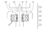
- a heating device 41 installed at a location indicated by an arrow A in FIG. 11has a coil 43 wound in one direction around a rotor shaft 113 as shown in FIG. Further, a groove is dug in the outer peripheral surface of the rotor shaft 113, and an object to be heated 45 having electrical conductivity is embedded in the groove. An alternating current is passed through the coil 43, and an alternating magnetic field is generated around it. This AC magnetic field intersects the object 45 to be heated, thereby generating an eddy current in the object 45 to be heated, and this eddy current can cause an eddy current loss P e . Therefore, the object 45 to be heated generates heat. Since the object to be heated 45 can be directly heated instead of the conventional heating by radiant heat when the base portion 129 is heated, the rotating body 103 can be efficiently heated.
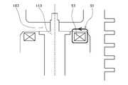
- a heating device 51 installed at a location indicated by an arrow B in FIG. 11is constructed by winding a coil 53 in one direction around a rotor shaft 113 as shown in FIG.
- An alternating currentis passed through the coil 53, and an alternating magnetic field is generated around it.
- This AC magnetic fieldintersects the rotor blade 102 to generate an eddy current in the rotor blade 102, and this eddy current can cause an eddy current loss Pe . Therefore, the rotor blade 102 generates heat. Since the rotor blades 102 can be directly heated, the rotor 103 can be efficiently heated.
- the heating device 61installed at the location indicated by arrow C in FIG. It consists of being An alternating current is passed through the coil 63, and an alternating magnetic field is generated around it. This AC magnetic field intersects the rotor blade 102 to generate an eddy current in the rotor blade 102, and this eddy current can cause an eddy current loss Pe . Therefore, the rotor blade 102 generates heat. Since the rotor blades 102 can be directly heated, the rotor 103 can be efficiently heated.
- the heating device 71installed at the location indicated by arrow D in FIG. It is configured.
- An alternating currentis passed through the coil 71 and an alternating magnetic field is generated around it.
- This AC magnetic fieldintersects the cylindrical portion 102d of the rotor blade 102 to generate an eddy current in the rotor blade 102, which can cause an eddy current loss Pe . Therefore, the rotor blade 102 generates heat. Since the rotor blades 102 can be directly heated, the rotor 103 can be efficiently heated.
- the coil 73may be embedded in the stator column 122 side. By causing the AC magnetic field generated by the coil 73 to intersect the cylindrical portion 102d of the rotor blade 102, an eddy current loss P e may be generated.
- a plurality of blades 81are attached to the head of the rotor shaft 113 .
- a coil 83is arranged on the stator side so as to face the tip of the blade 81 .
- An alternating currentis passed through the coil 83, and an alternating magnetic field is generated around it.
- This AC magnetic fieldintersects the tip portion of the blade 81 to generate an eddy current at the tip portion of the blade 81, and this eddy current can cause an eddy current loss Pe . Therefore, the blades 81 generate heat.
- coil 85may be arranged so as to face the side portion of blade 81 .
- the alternating magnetic field generated by coil 85intersects the sides of vane 81 .
- an eddy currentis generated on the side of the blade 81, and this eddy current can cause an eddy current loss P e .
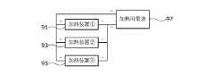
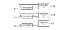
- FIG. 16shows an example in which a heating device 91 is provided for heating the rotor shaft 113, and a heating device 93 and a heating device 95 are provided at two axially separated locations for heating the rotor blades 102. indicate.
- the heating power supply 97may supply an alternating current by connecting a heating device 91, a heating device 93, and a heating device 95 in series, or as shown in FIG. Alternating current may be supplied by connecting the device 91, the heating device 93, and the heating device 95 in parallel.
- heating power supplies 97A, 97B, and 97Cmay be provided independently for each of the heating device 91, the heating device 93, and the heating device 95 to supply alternating current. .
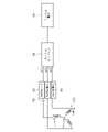
- the heating device 91is connected to the middle of the U-phase cable of the motor 121, the heating device 93 is connected to the middle of the V-phase cable, and the heating device 95 is connected to the middle of the W-phase cable.
- the motor power supply 19 and the motor inverter 18also serve as a heating power supply. Alternating current is supplied to the heating device 91 , the heating device 93 , and the heating device 95 from the motor power source 19 and the motor inverter 18 .
- the magnetic bearing power source 17may be configured to also serve as a heating power source.
- the heating power supplycan be configured with an inverter, LC resonance circuit, linear amplifier, etc.
- the heating power sourcemay be configured, for example, by installing an inverter in parallel with the motor inverter, connecting the output of the inverter to the heating device, and supplying power from the motor power source to the heating device.
- the motor power sourceis an alternating current commercial power source
- the motor power sourcemay be directly connected to the heating device and used as the heating power source.
- the power source for magnetic bearings and the power source for heatingare also used.
Landscapes
- Engineering & Computer Science (AREA)
- Mechanical Engineering (AREA)
- General Engineering & Computer Science (AREA)
- Physics & Mathematics (AREA)
- Thermal Sciences (AREA)
- Electromagnetism (AREA)
- Non-Positive Displacement Air Blowers (AREA)
- Magnetic Bearings And Hydrostatic Bearings (AREA)
- Structures Of Non-Positive Displacement Pumps (AREA)
Abstract
Description
Translated fromJapanese本発明は真空ポンプに係わり、特に回転体を交流磁界を用いて加熱することで、回転体の停止時も含めて生成物の付着を防止でき、また、回転体を高効率に加熱することのできる真空ポンプに関する。The present invention relates to a vacuum pump, and in particular, by heating a rotating body using an alternating magnetic field, it is possible to prevent adhesion of products even when the rotating body is stopped, and to heat the rotating body with high efficiency. It relates to a vacuum pump that can.
近年のエレクトロニクスの発展に伴い、メモリや集積回路といった半導体の需要が急激に増大している。
これらの半導体は、きわめて純度の高い半導体基板に不純物をドープして電気的性質を与えたり、エッチングにより半導体基板上に微細な回路を形成したりなどして製造される。With the recent development of electronics, the demand for semiconductors such as memories and integrated circuits is rapidly increasing.
These semiconductors are manufactured by doping a semiconductor substrate of extremely high purity with impurities to give it electrical properties, or by forming fine circuits on the semiconductor substrate by etching.
そして、これらの作業は空気中の塵等による影響を避けるため高真空状態のチャンバ内で行われる必要がある。このチャンバの排気には、一般に真空ポンプが用いられているが、特に残留ガスが少なく、保守が容易等の点から真空ポンプの中の一つであるターボ分子ポンプが多用されている。In addition, these operations must be performed in a high-vacuum chamber to avoid the effects of dust in the air. A vacuum pump is generally used to evacuate the chamber, and a turbo-molecular pump, which is one of the vacuum pumps, is often used because of its low residual gas and easy maintenance.
また、半導体の製造工程では、さまざまなプロセスガスを半導体の基板に作用させる工程が数多くあり、ターボ分子ポンプはチャンバ内を真空にするのみならず、これらのプロセスガスをチャンバ内から排気するのにも使用される。In addition, in the semiconductor manufacturing process, there are many processes in which various process gases are applied to the semiconductor substrate. is also used.
ところで、プロセスガスは、反応性を高めるため高温の状態でチャンバに導入される場合がある。そして、これらのプロセスガスは、排気される際に冷却されてある温度になると固体となり排気系に生成物を析出する場合がある。そして、この種のプロセスガスがターボ分子ポンプ内で低温となって固体状となり、ターボ分子ポンプ内部に付着して堆積する場合がある。By the way, the process gas may be introduced into the chamber at a high temperature in order to increase reactivity. When these process gases are cooled to a certain temperature during exhaust, they become solid and may deposit products in the exhaust system. In some cases, the process gas of this type becomes low temperature in the turbo-molecular pump, becomes solid, and adheres and deposits inside the turbo-molecular pump.
ターボ分子ポンプ内部にプロセスガスの析出物が堆積すると、この堆積物がポンプ流路を狭め、ターボ分子ポンプの性能を低下させる原因となる。
この問題を解決するために、ターボ分子ポンプについてはベース部周りにヒータを配設し、このヒータの加熱制御が行われている。When process gas deposits accumulate inside the turbomolecular pump, the deposits narrow the pump flow path and cause deterioration in the performance of the turbomolecular pump.
In order to solve this problem, a heater is provided around the base of the turbomolecular pump, and the heating of this heater is controlled.
ところで、生成物の付着をより一層効率よく防止するためには、ベース部周りやステータに対する加熱だけに限らず、回転体側についても加熱することが望まれる。
回転体への加熱の方法としては、例えば特許文献1には、永久磁石、電磁石により生成された直流磁界を回転体に交差させる方法が開示されている。また、特許文献2には、モータの効率を下げることで回転体を加熱させる方法が開示されている。更に、ステータ側を加熱し、その輻射熱で回転体側を加熱させる方法も考えられる。By the way, in order to prevent the adhesion of the product more efficiently, it is desirable to heat not only the surroundings of the base portion and the stator, but also the rotating body side.
As a method of heating the rotating body, for example,
ところで、かかる生成物の付着防止については、ポンプの運転中だけではなくポンプの停止時においても継続して行われることが望ましい。特許文献1の構成では、回転体に交差する磁界が直流であるため、交流電流を供給可能な加熱用電源を設ける必要がない一方で、回転体を加熱できるのは回転体の回転時のみであり、回転体の停止時には回転体を加熱することができない。
また、生成物の付着防止時の加熱制御については、加熱に必要な消費電力の効率化が求められる。By the way, it is desirable that the prevention of adhesion of such products should be continued not only during the operation of the pump but also when the pump is stopped. In the configuration of
In addition, with respect to heating control when preventing product adhesion, efficiency of power consumption required for heating is required.
本発明はこのような従来の課題に鑑みてなされたもので、回転体を交流磁界を用いて加熱することで、回転体の停止時も含めて生成物の付着を防止でき、また、回転体を高効率に加熱することのできる真空ポンプを提供することを目的とする。The present invention has been made in view of such conventional problems, and by heating the rotating body using an alternating magnetic field, it is possible to prevent the adhesion of products even when the rotating body is stopped, and to To provide a vacuum pump capable of heating with high efficiency.
このため本発明(請求項1)は、回転体と、該回転体を回転駆動させるモータと、該モータに回転駆動用の電力を供給するモータ用電源と、前記回転体を加熱するために所定の磁界周波数の交流磁界を発生させる加熱用電磁石と、該加熱用電磁石に交流電流によって電力を供給する加熱用電源とを備え、前記加熱用電磁石で発生された前記交流磁界を前記回転体と交差させることで前記回転体において、該交差した前記交流磁界の周囲に渦電流を発生させることを特徴とする。For this reason, the present invention (claim 1) comprises a rotating body, a motor for rotationally driving the rotating body, a motor power supply for supplying power for rotating the motor, and a predetermined heating device for heating the rotating body. and a heating power supply for supplying power to the heating electromagnet by alternating current, wherein the alternating magnetic field generated by the heating electromagnet intersects the rotating body. eddy currents are generated around the intersecting AC magnetic fields in the rotating body.
加熱用電磁石は、加熱用電源より供給された交流電流により、所定の磁界周波数の交流磁界を発生させる。交流磁界は、回転体と交差することで、回転体において、この交差した交流磁界の周囲に渦電流を発生させる。この渦電流により渦電流損が発生するため、回転体を加熱することができる。加熱用電磁石が発生させる磁界は交流磁界であるため回転体の回転が停止しているときでも渦電流損を生じさせることができ、回転体を加熱することができる。堆積物は回転体の停止中であっても生じることが想定されるので、堆積物の生成を効果的に防止できる。また、本発明では、回転体に渦電流損を直接発生させることができるため、ステータ側を加熱し、その輻射熱で回転体側を加熱させる場合と比べて、回転体を高効率に加熱することができる。The heating electromagnet generates an alternating magnetic field with a predetermined magnetic field frequency by alternating current supplied from the heating power supply. The alternating magnetic field intersects the rotating body, thereby generating eddy currents around the intersecting alternating magnetic field in the rotating body. Since this eddy current causes eddy current loss, the rotating body can be heated. Since the magnetic field generated by the heating electromagnet is an alternating magnetic field, eddy current loss can be generated even when the rotation of the rotating body is stopped, and the rotating body can be heated. Deposits are expected to form even while the rotating body is stopped, so the formation of deposits can be effectively prevented. In addition, in the present invention, since eddy current loss can be directly generated in the rotating body, the rotating body can be heated with high efficiency compared to the case where the stator side is heated and the rotating body side is heated by the radiant heat. can.
また、本発明(請求項2)は、前記回転体には前記交流磁界の交差の対象となる所定の導電性を有する加熱対象物が備えられたことを特徴とする。In addition, the present invention (claim 2) is characterized in that the rotating body is provided with a heating object having a predetermined conductivity to which the AC magnetic field intersects.
この手法では、回転体に加熱対象物を備えたことにより、効率よく渦電流を発生させることができる。このため、回転体を高効率に加熱することができる。With this method, eddy currents can be generated efficiently by equipping the rotating body with the object to be heated. Therefore, the rotating body can be heated with high efficiency.
更に、本発明(請求項3)は、前記回転体の剛体モード固有振動数をωresと定義したときに前記磁界周波数がωres/√2より大きいことを特徴とする。Furthermore, the present invention (claim 3) is characterized in that the magnetic field frequency is greater than ωres /√2 when the rigid body mode natural frequency of the rotating body is defined as ωres .
交流磁界は、回転体を加熱させる一方で、回転体への吸引力も同時に生ずる。この吸引力は、回転体の振動を大きくする原因になる。しかし、磁界周波数をωres/√2より大きくすることで、同一の大きさの磁束密度の直流磁界を回転体に交差させる場合と比べて、回転体の振動を小さくすることができる。While the AC magnetic field heats the rotating body, it also generates an attractive force to the rotating body at the same time. This attractive force causes the vibration of the rotating body to increase. However, by setting the magnetic field frequency higher than ωres /√2, the vibration of the rotating body can be reduced compared to the case where the DC magnetic field with the same magnetic flux density intersects the rotating body.
更に、本発明(請求項4)は、前記磁界周波数が前記回転体の機械角に基づき定義された定格回転周波数より大きいことを特徴とする。Furthermore, the present invention (claim 4) is characterized in that the magnetic field frequency is higher than the rated rotational frequency defined based on the mechanical angle of the rotating body.
一般に、回転体の回転によって発生するポンプの振動のスペクトルには、回転体の回転周波数成分の大きなピークが表れる。このピーク周波数は運転状態によって変化し、最大値は、回転体の機械角に基づき定義された定格回転周波数である。従って、回転体の機械角に基づき定義された定格回転周波数よりも加熱用電磁石で発生させる交流磁界の周波数が大きい場合には、交流磁界によって発生するポンプの振動スペクトルのピークが、回転体の回転によって発生する振動スペクトルのピークとは一致しない。そのため、ポンプの振動を小さくすることができる。In general, the spectrum of the pump vibration generated by the rotation of the rotating body shows a large peak of the rotation frequency component of the rotating body. This peak frequency varies depending on the operating conditions, and the maximum value is the rated rotational frequency defined based on the mechanical angle of the rotating body. Therefore, when the frequency of the alternating magnetic field generated by the heating electromagnet is higher than the rated rotational frequency defined based on the mechanical angle of the rotating body, the peak of the vibration spectrum of the pump generated by the alternating magnetic field does not coincide with the peaks in the vibrational spectrum generated by Therefore, vibration of the pump can be reduced.
更に、本発明(請求項5)は、前記磁界周波数が前記モータに流れる電流の定格回転時の周波数より大きいことを特徴とする。Furthermore, the present invention (claim 5) is characterized in that the magnetic field frequency is higher than the frequency of the current flowing through the motor at rated rotation.
一般に、モータに流れる電流によって発生するポンプの振動のスペクトルには、モータに流れる電流の周波数成分の大きなピークが表れる。このピーク周波数は運転状態によって変化し、最大値は、モータに流れる電流の定格回転時の周波数である。従って、モータに流れる電流の定格回転時の周波数よりも加熱用電磁石で発生させる交流磁界の周波数が大きい場合には、交流磁界によって発生するポンプの振動スペクトルのピークが、モータに流れる電流によって発生する振動スペクトルのピークとは一致しない。そのため、ポンプの振動を小さくすることができる。In general, the spectrum of the pump vibration generated by the current flowing in the motor shows a large peak of the frequency component of the current flowing in the motor. This peak frequency varies depending on the operating conditions, and the maximum value is the frequency of the current flowing through the motor at rated rotation. Therefore, when the frequency of the AC magnetic field generated by the heating electromagnet is higher than the frequency of the current flowing through the motor at the rated rotation, the peak of the vibration spectrum of the pump generated by the AC magnetic field is caused by the current flowing through the motor. It does not match the peak of the vibrational spectrum. Therefore, vibration of the pump can be reduced.
更に、本発明(請求項6)は、前記モータ用電源の出力電圧を変換し、前記モータに電圧を印加するモータ用インバータと、該モータ用インバータを制御するモータ用インバータ制御器とを備え、前記磁界周波数が前記モータ用インバータ制御器の制御周波数の半分より大きいことを特徴とする。Furthermore, the present invention (Claim 6) comprises a motor inverter that converts the output voltage of the motor power supply and applies a voltage to the motor, and a motor inverter controller that controls the motor inverter, The magnetic field frequency is more than half the control frequency of the motor inverter controller.
磁界周波数がモータ用インバータ制御器の制御周波数の半分より大きければ、モータ用インバータが、モータに流れる電流に重畳して交流電流を流し、モータの磁界に重畳して加熱用の交流磁界を発生させることで回転体を加熱する場合と比べて、大きい周波数の交流磁界で加熱できる。そのため、同一の回転体の渦電流損を得るのに必要な交流磁界の磁束密度を小さくでき、交流磁界によって回転体に発生する外力を小さくすることができ、回転体の振動を小さくすることができる。If the magnetic field frequency is greater than half of the control frequency of the inverter controller for the motor, the inverter for the motor causes the alternating current to flow superimposed on the current flowing in the motor, and superimpose it on the magnetic field of the motor to generate the alternating magnetic field for heating. As a result, the rotating body can be heated by an alternating magnetic field with a higher frequency than when the rotating body is heated. Therefore, the magnetic flux density of the alternating magnetic field required to obtain the same eddy current loss of the rotating body can be reduced, the external force generated on the rotating body by the alternating magnetic field can be reduced, and the vibration of the rotating body can be reduced. can.
更に、本発明(請求項7)は、前記回転体を空中に浮上支持する磁気軸受と、該磁気軸受に対して電力を供給する磁気軸受用電源と、前記磁気軸受用電源の出力電圧を変換し、前記磁気軸受に電圧を印加する磁気軸受用インバータと、該磁気軸受用インバータを制御する磁気軸受用インバータ制御器とを備え、前記磁界周波数が前記磁気軸受用インバータ制御器の制御周波数の半分より大きいことを特徴とする。Further, the present invention (claim 7) provides a magnetic bearing that levitates and supports the rotating body in the air, a magnetic bearing power source that supplies power to the magnetic bearing, and a magnetic bearing power source that converts the output voltage of the magnetic bearing power source. a magnetic bearing inverter for applying a voltage to the magnetic bearing; and a magnetic bearing inverter controller for controlling the magnetic bearing inverter, wherein the magnetic field frequency is half the control frequency of the magnetic bearing inverter controller. characterized by being greater than
磁界周波数が磁気軸受用インバータ制御器の制御周波数の半分より大きければ、磁気軸受用インバータが、磁気軸受に流れる電流に重畳して交流電流を流し、磁気軸受の磁界に重畳して加熱用の交流磁界を発生させることで回転体を加熱する場合と比べて、大きい周波数の交流磁界で加熱できる。そのため、同一の回転体の渦電流損を得るのに必要な交流磁界の磁束密度を小さくでき、交流磁界によって回転体に発生する外力を小さくすることができ、回転体の振動を小さくすることができる。If the magnetic field frequency is greater than half of the control frequency of the magnetic bearing inverter controller, the magnetic bearing inverter superimposes an alternating current on the current flowing through the magnetic bearing, and superimposes it on the magnetic field of the magnetic bearing to supply an alternating current for heating. Compared to the case of heating a rotating body by generating a magnetic field, it can be heated by an alternating magnetic field with a higher frequency. Therefore, the magnetic flux density of the alternating magnetic field required to obtain the same eddy current loss of the rotating body can be reduced, the external force generated on the rotating body by the alternating magnetic field can be reduced, and the vibration of the rotating body can be reduced. can.
更に、本発明(請求項8)は、前記回転体を空中に浮上支持する磁気軸受と、該磁気軸受に対して電力を供給する磁気軸受用電源と、前記回転体の位置を所定のセンサ周波数で変調された位置信号に基づき非接触に計測する変位センサと、前記位置信号を復調させるローパスフィルタを含む復調回路とを備え、前記磁界周波数が前記ローパスフィルタのカットオフ周波数より大きいことを特徴とする。Further, the present invention (claim 8) comprises a magnetic bearing that levitates and supports the rotating body in the air, a magnetic bearing power supply that supplies power to the magnetic bearing, and a sensor that detects the position of the rotating body at a predetermined sensor frequency. and a demodulation circuit including a low-pass filter for demodulating the position signal, wherein the magnetic field frequency is greater than the cutoff frequency of the low-pass filter. do.
磁界周波数が変位センサの位置信号を復調させるローパスフィルタのカットオフ周波数よりも大きければ、復調された変位センサの位置信号に含まれる、交流磁界によって発生するポンプの振動成分が小さくなる。そのため、交流磁界によって発生するポンプの振動は回転体の位置制御に影響を及ぼさず、より安定な磁気軸受制御を実現することができる。If the magnetic field frequency is higher than the cut-off frequency of the low-pass filter that demodulates the position signal of the displacement sensor, the vibration component of the pump generated by the AC magnetic field, which is included in the demodulated position signal of the displacement sensor, is reduced. Therefore, the vibration of the pump caused by the alternating magnetic field does not affect the position control of the rotating body, and more stable magnetic bearing control can be realized.
更に、本発明(請求項9)は、前記回転体を空中に浮上支持する磁気軸受と、該磁気軸受に対して電力を供給する磁気軸受用電源と、前記回転体の位置を所定のセンサ周波数で変調された位置信号に基づき非接触に計測する変位センサとを備え、前記磁界周波数が前記センサ周波数より大きいことを特徴とする。Further, the present invention (Claim 9) comprises a magnetic bearing that levitates and supports the rotating body in the air, a magnetic bearing power supply that supplies electric power to the magnetic bearing, and a sensor that detects the position of the rotating body at a predetermined sensor frequency. and a displacement sensor that performs non-contact measurement based on the position signal modulated by the magnetic field frequency is higher than the sensor frequency.
磁界周波数がセンサ周波数より大きければ、変位センサの位置信号に含まれる、交流磁界によって発生するポンプの振動成分が小さくなる。そのため、交流磁界によって発生するポンプの振動は回転体の位置制御に影響を及ぼさず、より安定な磁気軸受制御を実現することができる。If the magnetic field frequency is higher than the sensor frequency, the vibration component of the pump generated by the alternating magnetic field, which is included in the position signal of the displacement sensor, becomes smaller. Therefore, the vibration of the pump caused by the alternating magnetic field does not affect the position control of the rotating body, and more stable magnetic bearing control can be realized.
更に、本発明(請求項10)は、前記加熱用電源が前記モータ用電源と兼用されたことを特徴とする。Furthermore, the present invention (claim 10) is characterized in that the heating power supply is also used as the motor power supply.
加熱用電磁石に対してはモータ用電源から交流電流が供給される。このため、省スペースかつ安価に構成できる。Alternating current is supplied to the heating electromagnet from the motor power supply. Therefore, it can be configured in a space-saving manner and at a low cost.
更に、本発明(請求項11)は、前記回転体を空中に浮上支持する磁気軸受と、該磁気軸受に対して電力を供給する磁気軸受用電源を備え、前記加熱用電源が前記磁気軸受用電源と兼用されたことを特徴とする。Further, the present invention (Claim 11) comprises a magnetic bearing that levitates and supports the rotating body in the air, and a magnetic bearing power source that supplies power to the magnetic bearing, and the heating power source is for the magnetic bearing. It is characterized in that it is also used as a power source.
加熱用電磁石に対しては磁気軸受用電源から交流電流が供給される。このため、省スペースかつ安価に構成できる。Alternating current is supplied to the heating electromagnet from the magnetic bearing power supply. Therefore, it can be configured in a space-saving manner and at a low cost.
更に、本発明(請求項12)は、前記加熱用電源が前記磁気軸受用電源と兼用されたことを特徴とする。Furthermore, the present invention (Claim 12) is characterized in that the heating power supply is also used as the magnetic bearing power supply.
加熱用電磁石に対しては磁気軸受用電源から交流電流が供給される。このため、省スペースかつ安価に構成できる。Alternating current is supplied to the heating electromagnet from the magnetic bearing power supply. Therefore, it can be configured in a space-saving manner and at a low cost.
以上説明したように本発明によれば、回転体を加熱するために所定の磁界周波数の交流磁界を発生させる加熱用電磁石を備え、加熱用電磁石で発生された交流磁界を回転体と交差させるように構成したので、交流磁界は、回転体において、この交差した交流磁界の周囲に渦電流を発生させる。この渦電流により渦電流損が発生するため、回転体を加熱することができる。加熱用電磁石が発生させる磁界は交流磁界であるため、渦電流損は回転体の回転が停止しているときでも生じさせることができる。堆積物はポンプの停止中であっても生じることが想定されるので堆積物の生成を効果的に防止できる。また、回転体に直接渦電流損を発生させることができるため、回転体を高効率に加熱することができる。As described above, according to the present invention, a heating electromagnet for generating an alternating magnetic field with a predetermined magnetic field frequency is provided to heat the rotating body, and the alternating magnetic field generated by the heating electromagnet is made to intersect the rotating body. , the alternating magnetic field generates eddy currents around the crossed alternating magnetic field in the rotating body. Since this eddy current causes eddy current loss, the rotating body can be heated. Since the magnetic field generated by the heating electromagnet is an alternating magnetic field, eddy current loss can be generated even when the rotation of the rotating body is stopped. Since deposits are expected to occur even while the pump is stopped, the formation of deposits can be effectively prevented. In addition, since eddy current loss can be generated directly in the rotating body, the rotating body can be heated with high efficiency.
以下、本発明の実施形態について説明する。図1に本発明の実施形態で使用するターボ分子ポンプの構成図を示す。図1において、ターボ分子ポンプ100は、円筒状の外筒127の上端に吸気口101が形成されている。そして、外筒127の内方には、ガスを吸引排気するためのタービンブレードである複数の回転翼102(102a、102b、102c・・・)を周部に放射状かつ多段に形成した回転体103が備えられている。この回転体103の中心にはロータ軸113が取り付けられており、このロータ軸113は、例えば5軸制御の磁気軸受により空中に浮上支持かつ位置制御されている。回転体103は、一般的に、アルミニウム又はアルミニウム合金などの金属によって構成されている。Embodiments of the present invention will be described below. FIG. 1 shows a configuration diagram of a turbomolecular pump used in an embodiment of the present invention. In FIG. 1, a turbo-
上側径方向電磁石104は、4個の電磁石がX軸とY軸とに対をなして配置されている。この上側径方向電磁石104に近接して、かつ上側径方向電磁石104のそれぞれに対応して4個の上側径方向センサ107が備えられている。上側径方向センサ107は、例えば伝導巻線を有するインダクタンスセンサや渦電流センサなどが用いられ、ロータ軸113の位置に応じて変化するこの伝導巻線のインダクタンスの変化に基づいてロータ軸113の位置を検出する。この上側径方向センサ107はロータ軸113、すなわちそれに固定された回転体103の径方向変位を検出し、図2に示す制御装置200の内部の図示しない中央演算処理装置(CPU)に送るように構成されている。The upper
この中央演算処理装置においては、磁気軸受制御器の機能が搭載されており、例えばPID調節機能を有する補償回路が、上側径方向センサ107によって検出された位置信号に基づいて、上側径方向電磁石104の励磁制御指令信号を生成し、図2に示す磁気軸受用インバータ16が、この励磁制御指令信号に基づいて、上側径方向電磁石104を励磁制御することで、ロータ軸113の上側の径方向位置が調整される。This central processing unit is equipped with the function of a magnetic bearing controller. For example, a compensation circuit having a PID control function controls the upper
そして、このロータ軸113は、高透磁率材(鉄、ステンレスなど)などにより形成され、上側径方向電磁石104の磁力により吸引されるようになっている。かかる調整は、X軸方向とY軸方向とにそれぞれ独立して行われる。また、下側径方向電磁石105及び下側径方向センサ108が、上側径方向電磁石104及び上側径方向センサ107と同様に配置され、ロータ軸113の下側の径方向位置を上側の径方向位置と同様に調整している。The
さらに、軸方向電磁石106A、106Bが、ロータ軸113の下部に備えた円板状の金属ディスク111を上下に挟んで配置されている。金属ディスク111は、鉄などの高透磁率材で構成されている。ロータ軸113の軸方向変位を検出するために軸方向センサ109が備えられ、その軸方向位置信号が制御装置200の中央演算処理装置(CPU)に送られるように構成されている。Furthermore, the
そして、中央演算処理装置に搭載された磁気軸受制御器において、例えばPID調節機能を有する補償回路が、軸方向センサ109によって検出された軸方向位置信号に基づいて、軸方向電磁石106Aと軸方向電磁石106Bのそれぞれの励磁制御指令信号を生成し、磁気軸受用インバータ16が、これらの励磁制御指令信号に基づいて、軸方向電磁石106Aと軸方向電磁石106Bをそれぞれ励磁制御することで、軸方向電磁石106Aが磁力により金属ディスク111を上方に吸引し、軸方向電磁石106Bが金属ディスク111を下方に吸引し、ロータ軸113の軸方向位置が調整される。Then, in the magnetic bearing controller mounted on the central processing unit, a compensating circuit having, for example, a PID control function detects
このように、制御装置200は、この軸方向電磁石106A、106Bが金属ディスク111に及ぼす磁力を適当に調節し、ロータ軸113を軸方向に磁気浮上させ、空間に非接触で保持するようになっている。Thus, the
一方、モータ121は、ロータ軸113を取り囲むように周状に配置された複数の磁極を備えている。各磁極は、ロータ軸113との間に作用する電磁力を介してロータ軸113を回転駆動するように、制御装置200によって制御されている。また、モータ121には図示しない例えばホール素子、レゾルバ、エンコーダなどの回転速度センサが組み込まれており、この回転速度センサの検出信号によりロータ軸113の回転速度が検出されるようになっている。On the other hand, the
さらに、例えば下側径方向センサ108近傍に、図示しない位相センサが取り付けてあり、ロータ軸113の回転の位相を検出するようになっている。制御装置200では、この位相センサと回転速度センサの検出信号を共に用いて磁極の位置を検出するようになっている。
回転翼102(102a、102b、102c・・・)とわずかの空隙を隔てて複数枚の固定翼123(123a、123b、123c・・・)が配設されている。回転翼102(102a、102b、102c・・・)は、それぞれ排気ガスの分子を衝突により下方向に移送するため、ロータ軸113の軸線に垂直な平面から所定の角度だけ傾斜して形成されている。固定翼123(123a、123b、123c・・・)は、例えばアルミニウム、鉄、ステンレス、銅などの金属、又はこれらの金属を成分として含む合金などの金属によって構成されている。Furthermore, a phase sensor (not shown) is attached, for example, near the lower
A plurality of fixed wings 123 (123a, 123b, 123c, . The rotor blades 102 (102a, 102b, 102c, . . . ) are inclined at a predetermined angle from a plane perpendicular to the axis of the
また、固定翼123も、同様にロータ軸113の軸線に垂直な平面から所定の角度だけ傾斜して形成され、かつ外筒127の内方に向けて回転翼102の段と互い違いに配設されている。そして、固定翼123の外周端は、複数の段積みされた固定翼スペーサ125(125a、125b、125c・・・)の間に嵌挿された状態で支持されている。
固定翼スペーサ125はリング状の部材であり、例えばアルミニウム、鉄、ステンレス、銅などの金属、又はこれらの金属を成分として含む合金などの金属によって構成されている。固定翼スペーサ125の外周には、わずかの空隙を隔てて外筒127が固定されている。外筒127の底部にはベース部129が配設されている。ベース部129には排気口133が形成され、外部に連通されている。チャンバ(真空チャンバ)側から吸気口101に入ってベース部129に移送されてきた排気ガスは、排気口133へと送られる。Similarly, the fixed blades 123 are also inclined at a predetermined angle from a plane perpendicular to the axis of the
The stationary wing spacer 125 is a ring-shaped member, and is made of, for example, metal such as aluminum, iron, stainless steel, or copper, or metal such as an alloy containing these metals as components. An
さらに、ターボ分子ポンプ100の用途によって、固定翼スペーサ125の下部とベース部129の間には、ネジ付スペーサ131が配設される。ネジ付スペーサ131は、アルミニウム、銅、ステンレス、鉄、又はこれらの金属を成分とする合金などの金属によって構成された円筒状の部材であり、その内周面に螺旋状のネジ溝131aが複数条刻設されている。ネジ溝131aの螺旋の方向は、回転体103の回転方向に排気ガスの分子が移動したときに、この分子が排気口133の方へ移送される方向である。回転体103の回転翼102(102a、102b、102c・・・)に続く最下部には円筒部102dが垂下されている。この円筒部102dの外周面は、円筒状で、かつネジ付スペーサ131の内周面に向かって張り出されており、このネジ付スペーサ131の内周面と所定の隙間を隔てて近接されている。回転翼102および固定翼123によってネジ溝131aに移送されてきた排気ガスは、ネジ溝131aに案内されつつベース部129へと送られる。Further, a threaded
ベース部129は、ターボ分子ポンプ100の基底部を構成する円盤状の部材であり、一般には鉄、アルミニウム、ステンレスなどの金属によって構成されている。ベース部129はターボ分子ポンプ100を物理的に保持すると共に、熱の伝導路の機能も兼ね備えているので、鉄、アルミニウムや銅などの剛性があり、熱伝導率も高い金属が使用されるのが望ましい。The
かかる構成において、回転翼102がロータ軸113と共にモータ121により回転駆動されると、回転翼102と固定翼123の作用により、吸気口101を通じて図示しないチャンバから排気ガスが吸気される。回転翼102の回転速度は通常20,000rpm~90,000rpmであり、回転翼102の先端での周速度は200m/s~400m/sに達する。吸気口101から吸気された排気ガスは、回転翼102と固定翼123の間を通り、ベース部129へ移送される。In this configuration, when the
なお、上記では、ネジ付スペーサ131は回転体103の円筒部102dの外周に配設し、ネジ付スペーサ131の内周面にネジ溝131aが刻設されているとして説明した。
しかしながら、これとは逆に円筒部102dの外周面にネジ溝が刻設され、その周囲に円筒状の内周面を有するスペーサが配置される場合もある。In the above description, the threaded
However, in some cases, conversely, a thread groove is formed on the outer peripheral surface of the
また、ターボ分子ポンプ100の用途によっては、吸気口101から吸引されたガスが上側径方向電磁石104、上側径方向センサ107、モータ121、下側径方向電磁石105、下側径方向センサ108、軸方向電磁石106A、106B、軸方向センサ109などで構成される電装部に侵入することのないよう、電装部は周囲をステータコラム122で覆われ、このステータコラム122内はパージガスにて所定圧に保たれる場合もある。Further, depending on the application of the turbo-
この場合には、ベース部129には図示しない配管が配設され、この配管を通じてパージガスが導入される。導入されたパージガスは、保護ベアリング120とロータ軸113間、モータ121のロータとステータ間、ステータコラム122と回転翼102の内周側円筒部の間の隙間を通じて排気口133へ送出される。In this case, a pipe (not shown) is arranged in the
ここに、ターボ分子ポンプ100は、機種の特定と、個々に調整された固有のパラメータ(例えば、機種に対応する諸特性)に基づいた制御を要する。この制御パラメータを格納するために、上記ターボ分子ポンプ100は、その本体内に電子回路部141を備えている。電子回路部141は、EEP-ROM等の半導体メモリ及びそのアクセスのための半導体素子等の電子部品、それらの実装用の基板143等から構成される。この電子回路部141は、ターボ分子ポンプ100の下部を構成するベース部129の例えば中央付近の図示しない回転速度センサの下部に収容され、気密性の底蓋145によって閉じられている。Here, the turbo-
ところで、半導体の製造工程では、チャンバに導入されるプロセスガスの中には、その圧力が所定値よりも高くなり、或いは、その温度が所定値よりも低くなると、固体となる性質を有するものがある。ターボ分子ポンプ100内部では、排気ガスの圧力は、吸気口101で最も低く排気口133で最も高い。プロセスガスが吸気口101から排気口133へ移送される途中で、その圧力が所定値よりも高くなったり、その温度が所定値よりも低くなったりすると、プロセスガスは、固体状となり、ターボ分子ポンプ100内部に付着して堆積する。In the semiconductor manufacturing process, some of the process gases introduced into the chamber have the property of becoming solid when their pressure exceeds a predetermined value or their temperature falls below a predetermined value. be. Inside the
例えば、Alエッチング装置にプロセスガスとしてSiCl4が使用された場合、低真空(760[torr]~10-2[torr])かつ、低温(約20[℃])のとき、固体生成物(例えばAlCl3)が析出し、ターボ分子ポンプ100内部に付着堆積することが蒸気圧曲線からわかる。これにより、ターボ分子ポンプ100内部にプロセスガスの析出物が堆積すると、この堆積物がポンプ流路を狭め、ターボ分子ポンプ100の性能を低下させる原因となる。そして、前述した生成物は、排気口133付近やネジ付スペーサ131付近の圧力が高い部分で凝固、付着し易い状況にあった。For example, whenSiCl4 is used as a process gas in an Al etching apparatus, a solid product (eg, AlCl3 ) precipitates and deposits inside the
そのため、この問題を解決するために、従来はベース部129等の外周に図示しないヒータや環状の水冷管149を巻着させ、かつ例えばベース部129に図示しない温度センサ(例えばサーミスタ)を埋め込み、この温度センサの信号に基づいてベース部129の温度を一定の高い温度(設定温度)に保つようにヒータの加熱や水冷管149による冷却の制御(以下TMSという。TMS;Temperature Management System)が行われている。Therefore, in order to solve this problem, conventionally, a heater (not shown) or an annular water-cooling
次に、回転体103の加熱制御について説明する。
上述したように、ベース部129側についての加熱が従来行われているが、生成物の堆積防止によるポンプの運転効率向上のため、近年は更に回転体103側も含めた一層の加熱が望まれている。
このように回転体103の加熱制御を行う方法を図1と図2に基づき説明する。図1において、保護ベアリング1と上側径方向センサ107の間には、2極の加熱用電磁石3Aと加熱用電磁石3Bとがロータ軸113を隔てて対向して配設されている。この加熱用電磁石3Aと加熱用電磁石3Bとは加熱装置3に相当し、この加熱装置3に対しては図2に示すように、加熱用電源21より交流電流が供給されるようになっている。この交流電流により加熱用電磁石3Aと加熱用電磁石3Bは励磁され、交流磁界が発生するようになっている。Next, heating control of the
As described above, the
A method of controlling the heating of the
かかる構成において、発生した交流磁界はロータ軸113と交差する。交差した交流磁界の周囲には渦電流が発生する。このとき、ロータ軸113には図示しない導電性を有する加熱対象物が固着され、この加熱対象物に対して交流磁界が貫通し、渦電流が発生するようにしてもよい。加熱対象物の材料としては鉄、ステンレス、アルミニウムなどの導電性を有する金属が挙げられるが、鉄、ステンレスなどの強磁性体がより望ましい。そして、この渦電流により回転体103は加熱される。With such a configuration, the generated alternating magnetic field intersects the
交流磁界は、正弦波であってもよいし、方形波、三角波等の他の波形や、これらの足し合わせでもよい。また、この交流磁界に直流磁界がオフセットされてもよい。他の波形の場合には、各波形の基本波成分を磁界の周波数とみなす。The alternating magnetic field may be a sine wave, a square wave, a triangular wave, or any other waveform, or a combination thereof. Also, a DC magnetic field may be offset from this AC magnetic field. For other waveforms, the fundamental component of each waveform is taken as the frequency of the magnetic field.
このとき発生する渦電流損について「回転機械設計者のための磁気軸受ガイドブック」日本工業出版59ページ((2)渦電流損)によれば、板厚t、磁界の変動周波数f、磁界の変動を受ける磁性体の体積V、最大の磁束密度Bm、磁性体の固有抵抗ρと定義したときに渦電流損Peは数1で表せる。
[数1]
[Number 1]
また、交流磁界を回転体103と交差させる場合には、渦電流損Peはロータ軸113の回転が停止しているときでも生じさせることができる。堆積物はポンプの停止中であっても生じることが想定されるので堆積物の生成を効果的に防止できる。In addition, when the AC magnetic field intersects with the
次に、回転体103及びポンプの振動について検討する。回転体103の振動は、回転体103の故障の原因となる。特に、磁気軸受を用いて回転体103を浮上させているポンプでは、回転体103の振動の増大によって磁気軸受制御が不能となり、ロータ軸113が保護ベアリング1、120に接触するタッチダウンが発生するおそれがある。また、回転体103の振動は、軸受やモータ121などを介してポンプ全体へと伝わる。Next, the vibration of the
更に、ポンプのステータ部には、磁気軸受を構成する上側径方向電磁石104、下側径方向電磁石105、軸方向電磁石106A、106Bや、モータ121の電磁石、加熱装置3の加熱用電磁石3A、3Bなどが存在する。これらの電磁石においては、コイルに電流が流れて磁界が発生することで、磁界とコアの相互作用によりコアの変形が発生し、振動が発生する。この振動は、ポンプ全体へと伝わる。Further, in the stator portion of the pump, an upper
これらの振動の結果、騒音の発生や、吸気口101を介して図示しないチャンバ側に振動が伝わることによる半導体製造工程への悪影響などが発生するおそれがある。従って、回転体及びポンプの振動はなるべく抑制されることが望ましい。As a result of these vibrations, noise may be generated, and the vibration may be transmitted to the chamber side (not shown) through the
交流磁界をロータ軸113に対し交差させることに伴う回転体103の振動について検討する。
渦電流損Peを発生させるために交流磁界をロータ軸113に対し交差させると、この交流磁界により外力が生ずる。この交流磁界により外力の生じる様子を図3に示す。図3は図1、図2に示した2極の配置での磁界及び外力の様子を示している。等方的な極配置の場合には理想的には左右の外力FLとFRは均衡するはずである。しかしながら、現実には加工精度による形状のばらつきや、アンバランスによるロータ軸113の偏心、材料の磁性のばらつき等の要因によりロータ軸113への外力が発生する。また、非等方的な極配置の場合でも、ロータ軸113への外力が発生するおそれがある。このため、回転体103を低振動で安定に回すためには、ロータ軸113への外力FL、FRを小さくすることが望まれる。Vibration of
When an alternating magnetic field crosses the
交流磁界がロータ軸113に対し交差したことに伴い生ずる外力FRは、数2に示す通り加熱用電磁石3Bとロータ軸113間のギャップの磁束密度Bgの2乗に比例する。
[数2]
[数3]
[Number 2]
[Number 3]
時刻tにおけるギャップの磁束密度Bgを数4の振幅Bg1、角振動数ω0の正弦波と仮定すると、
[数4]
[数5]
[Number 4]
[Number 5]
ここに、数6なので、
[数6]
この外力FRによる影響を図4の強制振動モデルについて検討する。ここに、回転体・ステータの外力方向のバネ定数k、回転体・ステータの外力方向の減衰係数γ、回転体の質量m、磁界により与えられる外力Fと定義する。Here is the
[Number 6]
The influence of this external force FR will be examined with respect to the forced vibration model of FIG. Here, the spring constant k of the rotating body/stator in the external force direction, the damping coefficient γ of the rotating body/stator in the external force direction, the mass of the rotating body m, and the external force F given by the magnetic field are defined.
このとき、外力が加えられる方向の回転体剛体モード固有角振動数ωresは
[数7]
[数8]

[Number 8]
一方、減衰係数γが数10のときには、数11と定義する。
[数10]

[Number 10]
このとき、数12を満たす交流ならば、同一の磁束密度に対するロータ軸113の変位(強制振動の応答)が、数13の直流の場合と比べて小さくなる。そして、交流磁界の周波数が高くなればなるほどこの変位は小さくなる。この間の様子を図5に示す。
[数12]

[Number 12]
次に、この強制振動モデルについての証明を行う。
強制振動モデルの運動方程式を数14とし、F/mを数15の強制振動に基づく正弦波と仮定する。ただし、xはロータ軸の変位であり、ω1は外力Fの角振動数である。
[数14]

Assume that the equation of motion of the forced vibration model is Formula 14, and that F/m is a sine wave based on Formula 15 forcing vibration. where x is the displacement of the rotor shaft and ω1 is the angular frequency of the external force F.
[Number 14]
xの解を数16とおくと、aは数17となる。
[数16]

[数18]

[Number 16]
[Number 18]
一方、交流磁界をロータ軸に交差させた場合、外力Fは数20であり、直流成分と交流成分の和で表される。
[数20]
[数21]
[number 20]
[number 21]
よって、外力のうち、角振動数ω1の交流成分の振幅が数22未満ならば、交流磁界による強制振動のロータ軸113の変位の振幅は、交流磁界の磁束密度最大値と同一の直流磁界をかけた場合と比べて、小さい。
[数22]
[数23]


[number 22]
[number 23]
このため、数26を満たす交流磁界の周波数において、交流磁界による強制振動のロータ軸113の変位の振幅は、交流磁界の磁束密度最大値と同一の直流磁界をかけた場合と比べて、小さい。
[数26]
[Number 26]
次に、加熱装置の加熱用電磁石3A、3Bにて交流磁界が発生することにより、ポンプに発生する振動について検討する。図3において、加熱用電磁石3A、3Bは、主に積層鋼板やフェライトからなるコア6と、コア6の突極部7a、7bに捲回されたコイル4a、4bなどから構成される。コイル4a、4bに加熱用電源より供給された交流電流が流れることによって起磁力が発生し、交流電流と同一の周波数の交流磁界がコア6に発生する。発生した交流磁界は、ギャップを介してロータ軸113に交差し、磁力線の閉ループ5a、5bを形成する。Next, the vibration generated in the pump due to the alternating magnetic field generated by the
交流磁界の発生時には、交流磁界とコア6の相互作用によりコア6の変形が発生し、交流磁界の周波数成分の振動が加熱用電磁石3A、3Bに発生する。この加熱用電磁石3A、3Bの振動は、加熱用電磁石3A、3Bとポンプの結合部などを介して、ポンプ全体へと伝わっていく。When an alternating magnetic field is generated, the interaction between the alternating magnetic field and the
次に、回転体103の回転によって発生する回転体103の振動について検討する。回転体103が回転すると、加工精度による形状のばらつきや、アンバランスによる回転体103の偏心、材料の磁性のばらつき等の要因により、回転体103への外力が発生し、振動が発生する。この振動のスペクトルには、回転体103の回転周波数成分の大きなピークが表れる。このピーク周波数は運転状態によって変化し、最大値は、回転体103の機械角に基づき定義された定格回転周波数である。Next, the vibration of the
従って、回転体103の機械角に基づき定義された定格回転周波数よりも加熱用電磁石3A、3Bで発生させる交流磁界の周波数が大きい場合には、交流磁界によって発生するポンプの振動スペクトルのピークが、回転体103の回転によって発生する振動スペクトルのピークとは一致しない。そのため、ポンプの振動スペクトルのピークを小さくすることができる。Therefore, when the frequency of the alternating magnetic field generated by the
次に、モータ121に流れる電流によって発生するポンプの振動について検討する。モータ121は、コアにコイルが捲回された電磁石からなりポンプに固定されたステータと、ステータから発生した磁界との相互作用により発生したトルクを回転体に伝達するロータからなる。なお、モータ121が例えば永久磁石同期モータの場合には、定格回転時の電流の周波数は電気角周波数に等しく、また、この電気角周波数は機械角周波数×極対数で算出可能である。Next, the vibration of the pump caused by the current flowing through the
モータ121のステータでは、磁界とコアの相互作用によりコアの変形が発生し、モータに流れる電流の周波数成分の振動が発生する。この振動は、モータとポンプの結合部を介して、ポンプ全体へと伝わっていく。In the stator of the
モータ121の回転駆動についてはモータ用インバータ18を用いたPWM(Pulse Width Modulation)制御が行われている。図6に示すように、このPWM制御では、周期t0にて制御される。このときの制御周波数f0=1/t0はモータ用インバータ制御器の制御周波数に相当する。そして、モータ用インバータ18の出力可能な電圧の周波数fは、制御周波数f0の1/2倍のf=f0/2である。即ち、モータ用インバータ制御器の制御周波数の2倍より大きい周波数をもって交流磁界による回転体103の加熱を行えば、モータ用インバータ18が、モータ121に流れる電流に重畳して交流電流を流し、モータ121の磁界に重畳して加熱用の交流磁界を発生させることで回転体103を加熱する場合と比べて、大きい周波数の交流磁界で加熱できる。そのため、同一の回転体103の渦電流損を得るのに必要な交流磁界の磁束密度を小さくでき、交流磁界によって回転体103に発生する外力を小さくすることができ、回転体103の振動を小さくすることができる。PWM (Pulse Width Modulation) control using a
更に、この点は、磁気軸受を制御する磁気軸受用インバータ16を用いたPWM制御についても同様である。タイミングチャートは図6と同様なので省略する。図6と同様に、磁気軸受を制御するPWM制御についても周期t0にて制御される。即ち、磁気軸受用インバータ制御器の制御周波数の2倍より大きい周波数をもって交流磁界による回転体103の加熱を行えば、磁気軸受用インバータ16が、磁気軸受に流れる電流に重畳して交流電流を流し、磁気軸受の磁界に重畳して加熱用の交流磁界を発生させることで回転体103を加熱する場合と比べて、大きい周波数の交流磁界で加熱できる。そのため、同一の回転体103の渦電流損を得るのに必要な交流磁界の磁束密度を小さくでき、交流磁界によって回転体103に発生する外力を小さくすることができ、回転体103の振動を小さくすることができる。Furthermore, this point also applies to PWM control using the
更に、下側径方向センサ108や上側径方向センサ107には、インダクタンスセンサ若しくは渦電流センサが用いられている。この下側径方向センサ108や上側径方向センサ107で検出された変位信号に対しては所定のセンサ周波数の変調波が重畳されているが、この変調波を基に、加熱用電磁石3Aと加熱用電磁石3Bで発生させる交流磁界の好適な周波数を判断してみる。Furthermore, an inductance sensor or an eddy current sensor is used for the lower
図7において、下側径方向センサ108や上側径方向センサ107から出力された位置信号はローパスフィルタ(LPF)を含む復調回路11で復調された後、磁気軸受制御器13で信号調整された後、下側径方向電磁石105や上側径方向電磁石104を励磁駆動する。ローパスフィルタのカットオフ周波数(通過域平坦部から3dB低下する周波数)よりも加熱用電磁石3Aと加熱用電磁石3Bで発生させる交流磁界の周波数が大きければ、復調された変位センサの位置信号に含まれる、交流磁界によって発生するポンプの振動成分が小さくなる。そのため、交流磁界によって発生するポンプの振動は回転体103の位置制御に影響は及ぼさず、より安定な磁気軸受制御を実現することができる。In FIG. 7, the position signals output from the lower
また、加熱用電磁石3Aと加熱用電磁石3Bで発生させる交流磁界の周波数がセンサ周波数よりも大きければ、変位センサの位置信号に含まれる、交流磁界によって発生するポンプの振動成分が小さくなる。そのため、交流磁界によって発生するポンプの振動は回転体103の位置制御に影響を及ぼさず、より安定な磁気軸受制御を実現することができる。Also, if the frequency of the alternating magnetic field generated by the
次に、図1、図2の加熱装置3では加熱用電磁石3Aと加熱用電磁石3Bの2極で構成した例を示したが、図8に4極での加熱装置の構成例を示す。この場合、加熱装置23としては、加熱用電磁石23A、加熱用電磁石23B、加熱用電磁石23C、加熱用電磁石23Dが互いに90度ずつ隔ててロータ軸113周りに存在し、コイル24a、24b、24c、24dがコア26の突極部27a、27b、27c、27dに対し均等に配置される。そして、磁界はロータ軸113を通り、ロータ軸113周りに突極部27a、27b、27c、27dを通る4つの磁界の閉ループ25a、25b、25c、25dが形成される。Next, in the
また、図9には4極での加熱装置の別構成例を示す。この場合、加熱装置31としては、コの字状のコア36aの2つの突極部37a、37bに対しそれぞれ配設されたコイル34a、34bからなる加熱用電磁石33A、加熱用電磁石33Bとでx軸正方向に磁界の閉ループ35aが形成され、一方、コの字状のコア36bの2つの突極部37c、37dに対しそれぞれ配設されたコイル34c、34dからなる加熱用電磁石33C、加熱用電磁石33Dとでx軸負方向に磁界の閉ループ35bが形成される。In addition, FIG. 9 shows another configuration example of a four-pole heating device. In this case, the
更に、図10に2極での加熱装置の別構成例を示す。この場合、加熱装置41としては、コの字状のコア36aの2つの突極部37a、37bに対しそれぞれ配設されたコイル34a、34bからなる加熱用電磁石33A、加熱用電磁石33Bとでx軸正方向にのみ磁界の閉ループ35aが形成される。このように非対称に構成された場合でも回転体103に対し交差した交流磁界の周囲には渦電流損Peを生じさせることができる。Further, FIG. 10 shows another structural example of the heating device with two poles. In this case, the
加熱用電磁石のコイルは、一つの加熱用電源に対して直列に接続されるのが望ましい。しかし、加熱用電磁石のコイルを並列に接続したり、コイルに対して複数の加熱用電源を用意したりしてもよい。It is desirable that the heating electromagnet coil is connected in series with one heating power supply. However, the coils of the heating electromagnet may be connected in parallel, or a plurality of heating power sources may be provided for the coils.
また、各加熱用電磁石のコアの材料は、積層鋼板やフェライトなどの、導電率が小さく透磁率が大きいものが望ましい。しかし、例えば、通常の鉄やステンレスを使用してもよい。この構成は、回転体と同時にステータ側を加熱する場合に有用である。また、アルミニウムなどの非磁性金属や、プラスチックなどの絶縁体を用いたり、コア材料を使用しない空芯コイルを加熱用電磁石として用いたりしてもよい。In addition, it is desirable that the material of the core of each heating electromagnet has low conductivity and high magnetic permeability, such as laminated steel plate or ferrite. However, for example, ordinary iron or stainless steel may also be used. This configuration is useful when heating the rotor and the stator at the same time. Alternatively, a non-magnetic metal such as aluminum or an insulator such as plastic may be used, or an air-core coil without a core material may be used as the heating electromagnet.
次に、図11にターボ分子ポンプ100に対する加熱装置の設置方法について説明する。まず、図11中に矢印Aで示す箇所に設置される加熱装置41は、図12のようにロータ軸113の周囲に対しコイル43が一方向に捲回されている。また、ロータ軸113の外周面には溝が掘られ、この溝に対し導電性を有する加熱対象物45が埋設されている。そして、コイル43に対しては交流電流が流され、その周囲に交流磁界が生じている。この交流磁界は加熱対象物45に対し交差することで加熱対象物45では渦電流が発生し、この渦電流により渦電流損Peを生じさせることができる。このため、加熱対象物45は発熱する。従来のようなベース部129を加熱したときの輻射熱による加熱等ではなく、加熱対象物45を直接加熱することができるので、回転体103に対し効率のよい加熱を行うことができる。Next, a method of installing a heating device for the
また、図11中に矢印Bで示す箇所に設置される加熱装置51は、図13のようにロータ軸113の周囲に対しコイル53が一方向に捲回されることで構成されている。
そして、コイル53に対しては交流電流が流され、その周囲に交流磁界が生じている。この交流磁界は回転翼102に対し交差することで回転翼102では渦電流が発生し、この渦電流により渦電流損Peを生じさせることができる。このため、回転翼102は発熱する。回転翼102を直接加熱することができるので、回転体103に対し効率のよい加熱を行うことができる。11, a
An alternating current is passed through the
更に、図11中に矢印Cで示す箇所に設置される加熱装置61は、図14に示すように固定翼スペーサ125若しくは外筒127の内部にコイル63がロータ軸113周りに一方向に捲回されることで構成されている。
そして、このコイル63に対しては交流電流が流され、その周囲に交流磁界が生じている。この交流磁界は回転翼102に対し交差することで回転翼102では渦電流が発生し、この渦電流により渦電流損Peを生じさせることができる。このため、回転翼102は発熱する。回転翼102を直接加熱することができるので、回転体103に対し効率のよい加熱を行うことができる。Furthermore, the
An alternating current is passed through the
更に、図11中に矢印Dで示す箇所に設置される加熱装置71は、図14に示すようにネジ付スペーサ131の内部にコイル71がロータ軸113周りに一方向に捲回されることで構成されている。
そして、このコイル71に対しては交流電流が流され、その周囲に交流磁界が生じている。この交流磁界は回転翼102の円筒部102dに対し交差することで回転翼102では渦電流が発生し、この渦電流により渦電流損Peを生じさせることができる。このため、回転翼102は発熱する。回転翼102を直接加熱することができるので、回転体103に対し効率のよい加熱を行うことができる。
但し、ステータコラム122側にコイル73を埋設するようにしてもよい。そして、このコイル73で発生させた交流磁界を回転翼102の円筒部102dに対し交差させることで、渦電流損Peを生じさせるようにしてもよい。11, the
An alternating current is passed through the
However, the
次に、本発明の加熱装置を遠心式ポンプに適用した場合について説明する。図15に示すように、ロータ軸113の頭部には複数枚の羽根81が取り付けられている。羽根81の先端部に対峙するようにコイル83がステータ側に配設されている。そして、このコイル83に対しては交流電流が流され、その周囲に交流磁界が生じている。この交流磁界は羽根81の先端部分に対し交差することで羽根81の先端部分では渦電流が発生し、この渦電流により渦電流損Peを生じさせることができる。このため、羽根81は発熱する。
なお、羽根81の側部を加熱するために、羽根81の側部に対峙するようにコイル85が配設されてもよい。この場合には、コイル85で発生した交流磁界は羽根81の側部に交差する。このため、羽根81の側部では渦電流が発生し、この渦電流により渦電流損Peを生じさせることができる。Next, a case where the heating device of the present invention is applied to a centrifugal pump will be described. As shown in FIG. 15, a plurality of
In order to heat the side portion of
次に、本発明の加熱装置をポンプの複数箇所に配設したときの加熱用電源の接続方法について説明する。
図16には、ロータ軸113の加熱用に加熱装置91を配設し、一方、回転翼102の加熱用に加熱装置93と加熱装置95とを軸方向に隔てた2カ所に配設した例を示す。加熱用電源97は、図17に示すように、加熱装置91、加熱装置93、加熱装置95同士を直列に接続して交流電流の供給をしてもよいし、図18に示すように、加熱装置91、加熱装置93、加熱装置95同士を並列に接続して交流電流の供給をしてもよい。あるいは、図19に示すように、加熱装置91、加熱装置93、加熱装置95のそれぞれに対して独立して加熱用電源97A、97B、97Cを配設し、交流電流の供給をしてもよい。Next, a method of connecting a heating power source when the heating device of the present invention is installed at a plurality of locations of the pump will be described.
FIG. 16 shows an example in which a
また、図20に示すように、加熱装置91をモータ121のU相ケーブルの途中に接続、加熱装置93をV相ケーブルの途中に接続、加熱装置95をW相ケーブルの途中に接続するようにしてもよい。この場合には、モータ用電源19及びモータ用インバータ18は、加熱用電源を兼ねている。加熱装置91、加熱装置93、加熱装置95に対してはモータ用電源19及びモータ用インバータ18から交流電流が供給される。この場合、モータの三相に対して、それぞれ、同じ抵抗・インダクタンスの加熱装置を直列に接続するのが望ましい。しかしながら、モータのある相のみに接続したり、モータと加熱装置の接続が並列であったり、抵抗やインダクタンスが加熱装置毎に異なったりしていてもよい。Also, as shown in FIG. 20, the
図示は省略するが、この点は、磁気軸受用電源17についても同様であり、磁気軸受用電源17は加熱用電源を兼ねるように構成してもよい。Although illustration is omitted, the same applies to the magnetic
加熱用電源は、インバータ、LC共振回路、リニアアンプ等で構成が可能である。また、加熱用電源は、例えば、モータ用インバータと並列にインバータを設置してその出力を加熱装置に接続し、モータ用電源の電力を加熱装置に対して供給する構成となっていてもよい。また、例えば、モータ用電源が交流の商用電源である場合には、モータ用電源を直接加熱装置に接続することで、これを加熱用電源としてもよい。磁気軸受用電源と加熱用電源を兼用する場合にも、同様の構成が考えられる。The heating power supply can be configured with an inverter, LC resonance circuit, linear amplifier, etc. Further, the heating power source may be configured, for example, by installing an inverter in parallel with the motor inverter, connecting the output of the inverter to the heating device, and supplying power from the motor power source to the heating device. Further, for example, when the motor power source is an alternating current commercial power source, the motor power source may be directly connected to the heating device and used as the heating power source. A similar configuration is also conceivable when the power source for magnetic bearings and the power source for heating are also used.
なお、本発明は、本発明の精神を逸脱しない限り種々の改変をなすことができ、そして、本発明が当該改変されたものにも及ぶことは当然である。また、上述した各実施形態は種々組み合わせても良い。It should be noted that the present invention can be modified in various ways without departing from the spirit of the present invention, and it goes without saying that the present invention also extends to the modified ones. Also, the above-described embodiments may be combined in various ways.
1 保護ベアリング
3、23、31、41、51、61、71、91、93、95 加熱装置
3A、3B 加熱用電磁石
4a、4b、24a、24b、24c、24d、34a、34b、34c、34d コイル
5a、5b、25a、25b、25c、25d、35a、35b 磁界の閉ループ
6、26、36a、36b コア
7a、7b、27a、27b、27c、27d、37a、37b、37c、37d 突極部
11 復調回路
13 磁気軸受制御器
16 磁気軸受用インバータ
17 磁気軸受用電源
18 モータ用インバータ
19 モータ用電源
21、97、97A、97B、97C 加熱用電源
23A、23B、23C、23D、33A、33B、33C、33D 加熱用電磁石
43、53、63、71、73、83、85 コイル
45 加熱対象物
81 羽根
100 ターボ分子ポンプ
101 吸気口
102、102a、102b、102c 回転翼
102d 円筒部
103 回転体
104 上側径方向電磁石
105 下側径方向電磁石
106A、106B 軸方向電磁石
107 上側径方向センサ
108 下側径方向センサ
111 金属ディスク
113 ロータ軸
120 保護ベアリング
121 モータ
122 ステータコラム
123、123a、123b、123c 固定翼
125、125a、125b、125c 固定翼スペーサ
127 外筒
129 ベース部
131 ネジ付スペーサ
131a ネジ溝
200 制御装置1 protective bearings 3, 23, 31, 41, 51, 61, 71, 91, 93, 95 heating devices 3A, 3B heating electromagnets 4a, 4b, 24a, 24b, 24c, 24d, 34a, 34b, 34c, 34d coils 5a, 5b, 25a, 25b, 25c, 25d, 35a, 35b magnetic field closed loops 6, 26, 36a, 36b cores 7a, 7b, 27a, 27b, 27c, 27d, 37a, 37b, 37c, 37d salient pole portion 11 demodulation Circuit 13 Magnetic bearing controller 16 Magnetic bearing inverter 17 Magnetic bearing power supply 18 Motor inverter 19 Motor power supplies 21, 97, 97A, 97B, 97C Heating power supplies 23A, 23B, 23C, 23D, 33A, 33B, 33C, 33D heating electromagnets 43, 53, 63, 71, 73, 83, 85 coil 45 object to be heated 81 blade 100 turbomolecular pump 101 intake ports 102, 102a, 102b, 102c rotor blade 102d cylindrical portion 103 rotor 104 upper radial direction Electromagnet 105 Lower radial electromagnets 106A, 106B Axial electromagnet 107 Upper radial sensor 108 Lower radial sensor 111 Metal disk 113 Rotor shaft 120 Protective bearing 121 Motor 122 Stator column 123, 123a, 123b, 123c Fixed blades 125, 125a , 125b, 125c fixed wing spacer 127 outer cylinder 129 base portion 131 threaded spacer 131a thread groove 200 control device
Claims (12)
Translated fromJapanese該回転体を回転駆動させるモータと、
該モータに回転駆動用の電力を供給するモータ用電源と、
前記回転体を加熱するために所定の磁界周波数の交流磁界を発生させる加熱用電磁石と、
該加熱用電磁石に交流電流によって電力を供給する加熱用電源とを備え、
前記加熱用電磁石で発生された前記交流磁界を前記回転体と交差させることで前記回転体において、該交差した前記交流磁界の周囲に渦電流を発生させることを特徴とする真空ポンプ。a rotating body;
a motor for rotationally driving the rotating body;
a motor power source that supplies rotation driving power to the motor;
a heating electromagnet for generating an alternating magnetic field with a predetermined magnetic field frequency to heat the rotating body;
a heating power source that supplies power to the heating electromagnet with alternating current;
A vacuum pump, wherein the AC magnetic field generated by the heating electromagnet is crossed with the rotating body to generate an eddy current around the crossed AC magnetic field in the rotating body.
該モータ用インバータを制御するモータ用インバータ制御器とを備え、
前記磁界周波数が前記モータ用インバータ制御器の制御周波数の半分より大きいことを特徴とする請求項1又は請求項2記載の真空ポンプ。a motor inverter that converts the output voltage of the motor power source and applies voltage to the motor;
a motor inverter controller for controlling the motor inverter,
3. A vacuum pump according to claim 1, wherein said magnetic field frequency is greater than half the control frequency of said motor inverter controller.
該磁気軸受に対して電力を供給する磁気軸受用電源と、
前記磁気軸受用電源の出力電圧を変換し、前記磁気軸受に電圧を印加する磁気軸受用インバータと、
該磁気軸受用インバータを制御する磁気軸受用インバータ制御器とを備え、
前記磁界周波数が前記磁気軸受用インバータ制御器の制御周波数の半分より大きいことを特徴とする請求項1又は請求項2記載の真空ポンプ。a magnetic bearing that floats and supports the rotating body in the air;
a magnetic bearing power source that supplies power to the magnetic bearing;
a magnetic bearing inverter that converts the output voltage of the magnetic bearing power supply and applies a voltage to the magnetic bearing;
a magnetic bearing inverter controller for controlling the magnetic bearing inverter,
3. A vacuum pump according to claim 1, wherein said magnetic field frequency is greater than half the control frequency of said magnetic bearing inverter controller.
該磁気軸受に対して電力を供給する磁気軸受用電源と、
前記回転体の位置を所定のセンサ周波数で変調された位置信号に基づき非接触に計測する変位センサと、
前記位置信号を復調させるローパスフィルタを含む復調回路とを備え、
前記磁界周波数が前記ローパスフィルタのカットオフ周波数より大きいことを特徴とする請求項1又は請求項2記載の真空ポンプ。a magnetic bearing that floats and supports the rotating body in the air;
a magnetic bearing power source that supplies power to the magnetic bearing;
a displacement sensor for contactlessly measuring the position of the rotating body based on a position signal modulated at a predetermined sensor frequency;
a demodulation circuit including a low-pass filter for demodulating the position signal,
3. A vacuum pump according to claim 1, wherein said magnetic field frequency is higher than the cutoff frequency of said low-pass filter.
該磁気軸受に対して電力を供給する磁気軸受用電源と、
前記回転体の位置を所定のセンサ周波数で変調された位置信号に基づき非接触に計測する変位センサとを備え、
前記磁界周波数が前記センサ周波数より大きいことを特徴とする請求項1又は請求項2記載の真空ポンプ。a magnetic bearing that floats and supports the rotating body in the air;
a magnetic bearing power source that supplies power to the magnetic bearing;
a displacement sensor for contactlessly measuring the position of the rotating body based on a position signal modulated at a predetermined sensor frequency;
3. A vacuum pump according to claim 1, wherein said magnetic field frequency is greater than said sensor frequency.
Priority Applications (5)
| Application Number | Priority Date | Filing Date | Title |
|---|---|---|---|
| US18/563,762US20240369064A1 (en) | 2021-06-18 | 2022-06-09 | Vacuum pump |
| EP22824914.0AEP4357617A4 (en) | 2021-06-18 | 2022-06-09 | VACUUM PUMP |
| CN202280037862.4ACN117377828A (en) | 2021-06-18 | 2022-06-09 | Vacuum pump |
| IL308497AIL308497A (en) | 2021-06-18 | 2022-06-09 | Vacuum pump |
| KR1020237038378AKR20240019076A (en) | 2021-06-18 | 2022-06-09 | vacuum pump |
Applications Claiming Priority (2)
| Application Number | Priority Date | Filing Date | Title |
|---|---|---|---|
| JP2021-101957 | 2021-06-18 | ||
| JP2021101957AJP2023000891A (en) | 2021-06-18 | 2021-06-18 | Vacuum pump |
Publications (1)
| Publication Number | Publication Date |
|---|---|
| WO2022264924A1true WO2022264924A1 (en) | 2022-12-22 |
Family
ID=84527521
Family Applications (1)
| Application Number | Title | Priority Date | Filing Date |
|---|---|---|---|
| PCT/JP2022/023381CeasedWO2022264924A1 (en) | 2021-06-18 | 2022-06-09 | Vacuum pump |
Country Status (8)
| Country | Link |
|---|---|
| US (1) | US20240369064A1 (en) |
| EP (1) | EP4357617A4 (en) |
| JP (1) | JP2023000891A (en) |
| KR (1) | KR20240019076A (en) |
| CN (1) | CN117377828A (en) |
| IL (1) | IL308497A (en) |
| TW (1) | TW202303001A (en) |
| WO (1) | WO2022264924A1 (en) |
Cited By (1)
| Publication number | Priority date | Publication date | Assignee | Title |
|---|---|---|---|---|
| WO2025191420A1 (en)* | 2024-03-11 | 2025-09-18 | Edwards Japan Limited | Vacuum pump |
Citations (6)
| Publication number | Priority date | Publication date | Assignee | Title |
|---|---|---|---|---|
| JPS5932697A (en) | 1982-05-03 | 1984-02-22 | アルツ−ル・フアイフエル・ヴア−クウムテクニツク・ヴエツツラ−・ゲ−エムベ−ハ− | Heater for pump and turbo molecular pump with heater |
| JPH01130096U (en)* | 1988-02-29 | 1989-09-05 | ||
| JPH0512691U (en)* | 1991-07-24 | 1993-02-19 | 株式会社島津製作所 | Turbo molecular pump |
| WO2014119191A1 (en)* | 2013-01-31 | 2014-08-07 | エドワーズ株式会社 | Vacuum pump |
| JP2018204441A (en)* | 2017-05-30 | 2018-12-27 | 株式会社島津製作所 | Vacuum pump |
| JP2019031969A (en) | 2017-08-09 | 2019-02-28 | プファイファー・ヴァキューム・ゲーエムベーハー | Method of heating rotor of vacuum pump |
Family Cites Families (7)
| Publication number | Priority date | Publication date | Assignee | Title |
|---|---|---|---|---|
| JP2003254285A (en)* | 2002-02-28 | 2003-09-10 | Boc Edwards Technologies Ltd | Pump device |
| JP6171375B2 (en)* | 2013-02-06 | 2017-08-02 | 株式会社島津製作所 | Magnetic bearing device and vacuum pump |
| JP6144527B2 (en)* | 2013-04-16 | 2017-06-07 | エドワーズ株式会社 | Magnetic bearing device and vacuum pump equipped with the magnetic bearing device |
| JP6705169B2 (en)* | 2015-12-28 | 2020-06-03 | 株式会社島津製作所 | Monitoring device and monitoring program |
| JP6776971B2 (en)* | 2017-03-27 | 2020-10-28 | 株式会社島津製作所 | Vacuum pump and pump-integrated power supply |
| JP6942610B2 (en)* | 2017-07-14 | 2021-09-29 | エドワーズ株式会社 | A method for diagnosing a vacuum pump, a temperature control control device applied to the vacuum pump, an inspection jig, and a temperature control function unit. |
| JP7155531B2 (en)* | 2018-02-14 | 2022-10-19 | 株式会社島津製作所 | Magnetic levitation controller and vacuum pump |
- 2021
- 2021-06-18JPJP2021101957Apatent/JP2023000891A/enactivePending
- 2022
- 2022-05-16TWTW111118256Apatent/TW202303001A/enunknown
- 2022-06-09EPEP22824914.0Apatent/EP4357617A4/enactivePending
- 2022-06-09CNCN202280037862.4Apatent/CN117377828A/enactivePending
- 2022-06-09WOPCT/JP2022/023381patent/WO2022264924A1/ennot_activeCeased
- 2022-06-09USUS18/563,762patent/US20240369064A1/enactivePending
- 2022-06-09ILIL308497Apatent/IL308497A/enunknown
- 2022-06-09KRKR1020237038378Apatent/KR20240019076A/enactivePending
Patent Citations (6)
| Publication number | Priority date | Publication date | Assignee | Title |
|---|---|---|---|---|
| JPS5932697A (en) | 1982-05-03 | 1984-02-22 | アルツ−ル・フアイフエル・ヴア−クウムテクニツク・ヴエツツラ−・ゲ−エムベ−ハ− | Heater for pump and turbo molecular pump with heater |
| JPH01130096U (en)* | 1988-02-29 | 1989-09-05 | ||
| JPH0512691U (en)* | 1991-07-24 | 1993-02-19 | 株式会社島津製作所 | Turbo molecular pump |
| WO2014119191A1 (en)* | 2013-01-31 | 2014-08-07 | エドワーズ株式会社 | Vacuum pump |
| JP2018204441A (en)* | 2017-05-30 | 2018-12-27 | 株式会社島津製作所 | Vacuum pump |
| JP2019031969A (en) | 2017-08-09 | 2019-02-28 | プファイファー・ヴァキューム・ゲーエムベーハー | Method of heating rotor of vacuum pump |
Non-Patent Citations (2)
| Title |
|---|
| "Magnetic Bearing Guidebook for Rotating Machine Designers", JAPAN INDUSTRIAL PUBLISHING CO. |
| See also references ofEP4357617A4 |
Cited By (1)
| Publication number | Priority date | Publication date | Assignee | Title |
|---|---|---|---|---|
| WO2025191420A1 (en)* | 2024-03-11 | 2025-09-18 | Edwards Japan Limited | Vacuum pump |
Also Published As
| Publication number | Publication date |
|---|---|
| EP4357617A4 (en) | 2025-05-28 |
| IL308497A (en) | 2024-01-01 |
| US20240369064A1 (en) | 2024-11-07 |
| JP2023000891A (en) | 2023-01-04 |
| KR20240019076A (en) | 2024-02-14 |
| TW202303001A (en) | 2023-01-16 |
| CN117377828A (en) | 2024-01-09 |
| EP4357617A1 (en) | 2024-04-24 |
Similar Documents
| Publication | Publication Date | Title |
|---|---|---|
| CN111033948B (en) | Alternate pole rotors, motors, compressors, blowers and air conditioners | |
| Gruber et al. | Bearingless segment motor with five stator elements—Design and optimization | |
| Tera et al. | Performances of bearingless and sensorless induction motor drive based on mutual inductances and rotor displacements estimation | |
| WO2019125718A1 (en) | Homopolar bearingless slice motors | |
| Zad et al. | Design and analysis of a novel bearingless motor for a miniature axial flow blood pump | |
| JP2020204323A (en) | fan | |
| JPH11513558A (en) | Rotary machine for delivering fluid | |
| Mitterhofer et al. | Design aspects and test results of a high speed bearingless drive | |
| KR102106659B1 (en) | Electromagnetic rotating device and vacuum pump equipped with electromagnetic rotating device | |
| Sugimoto et al. | Axial vibration suppression by field flux regulation in two-axis actively positioned permanent magnet bearingless motors with axial position estimation | |
| CN108457984A (en) | Magnetic bearing device and vacuum pump | |
| KR100707235B1 (en) | Magnetic bearing type vacuum pump | |
| WO2022264924A1 (en) | Vacuum pump | |
| Li et al. | Basic characteristics of a 4kW permanent-magnet type bearingless slice motor for centrifugal pump system | |
| CN112088487B (en) | Motor system and turbo compressor including the same | |
| WO2022030374A1 (en) | Vacuum pump and rotor blade for vacuum pump | |
| CN114729646A (en) | Vacuum exhaust apparatus and vacuum pump used for the same | |
| JP7614247B2 (en) | Vacuum pump, magnetic bearing control device, and compression/decompression method | |
| JP2024129334A (en) | Vacuum pump | |
| KR20230082608A (en) | A vacuum pump, and a rotating cylinder provided in the vacuum pump | |
| Gruber et al. | Novel bearingless segment motor design with axial magnetized rotor magnets | |
| Karutz et al. | Maximizing acceleration capability of magnetically levitated slice motors | |
| JP2003269370A (en) | Pump device | |
| JP2003269368A (en) | Vacuum pump | |
| JP2004100624A (en) | Vacuum pump system |
Legal Events
| Date | Code | Title | Description |
|---|---|---|---|
| 121 | Ep: the epo has been informed by wipo that ep was designated in this application | Ref document number:22824914 Country of ref document:EP Kind code of ref document:A1 | |
| WWE | Wipo information: entry into national phase | Ref document number:308497 Country of ref document:IL | |
| WWE | Wipo information: entry into national phase | Ref document number:202280037862.4 Country of ref document:CN | |
| WWE | Wipo information: entry into national phase | Ref document number:2022824914 Country of ref document:EP | |
| NENP | Non-entry into the national phase | Ref country code:DE | |
| ENP | Entry into the national phase | Ref document number:2022824914 Country of ref document:EP Effective date:20240118 |