WO2022264829A1 - Cleaning method and plasma processing device - Google Patents
Cleaning method and plasma processing deviceDownload PDFInfo
- Publication number
- WO2022264829A1 WO2022264829A1PCT/JP2022/022512JP2022022512WWO2022264829A1WO 2022264829 A1WO2022264829 A1WO 2022264829A1JP 2022022512 WJP2022022512 WJP 2022022512WWO 2022264829 A1WO2022264829 A1WO 2022264829A1
- Authority
- WO
- WIPO (PCT)
- Prior art keywords
- gas
- concentration
- plasma
- seasoning
- chamber
- Prior art date
- Legal status (The legal status is an assumption and is not a legal conclusion. Google has not performed a legal analysis and makes no representation as to the accuracy of the status listed.)
- Ceased
Links
Images


Classifications
- C—CHEMISTRY; METALLURGY
- C23—COATING METALLIC MATERIAL; COATING MATERIAL WITH METALLIC MATERIAL; CHEMICAL SURFACE TREATMENT; DIFFUSION TREATMENT OF METALLIC MATERIAL; COATING BY VACUUM EVAPORATION, BY SPUTTERING, BY ION IMPLANTATION OR BY CHEMICAL VAPOUR DEPOSITION, IN GENERAL; INHIBITING CORROSION OF METALLIC MATERIAL OR INCRUSTATION IN GENERAL
- C23C—COATING METALLIC MATERIAL; COATING MATERIAL WITH METALLIC MATERIAL; SURFACE TREATMENT OF METALLIC MATERIAL BY DIFFUSION INTO THE SURFACE, BY CHEMICAL CONVERSION OR SUBSTITUTION; COATING BY VACUUM EVAPORATION, BY SPUTTERING, BY ION IMPLANTATION OR BY CHEMICAL VAPOUR DEPOSITION, IN GENERAL
- C23C16/00—Chemical coating by decomposition of gaseous compounds, without leaving reaction products of surface material in the coating, i.e. chemical vapour deposition [CVD] processes
- C23C16/44—Chemical coating by decomposition of gaseous compounds, without leaving reaction products of surface material in the coating, i.e. chemical vapour deposition [CVD] processes characterised by the method of coating
- C23C16/50—Chemical coating by decomposition of gaseous compounds, without leaving reaction products of surface material in the coating, i.e. chemical vapour deposition [CVD] processes characterised by the method of coating using electric discharges
- C23C16/511—Chemical coating by decomposition of gaseous compounds, without leaving reaction products of surface material in the coating, i.e. chemical vapour deposition [CVD] processes characterised by the method of coating using electric discharges using microwave discharges
- H—ELECTRICITY
- H01—ELECTRIC ELEMENTS
- H01L—SEMICONDUCTOR DEVICES NOT COVERED BY CLASS H10
- H01L21/00—Processes or apparatus adapted for the manufacture or treatment of semiconductor or solid state devices or of parts thereof
- H01L21/02—Manufacture or treatment of semiconductor devices or of parts thereof
- H01L21/04—Manufacture or treatment of semiconductor devices or of parts thereof the devices having potential barriers, e.g. a PN junction, depletion layer or carrier concentration layer
- H01L21/18—Manufacture or treatment of semiconductor devices or of parts thereof the devices having potential barriers, e.g. a PN junction, depletion layer or carrier concentration layer the devices having semiconductor bodies comprising elements of Group IV of the Periodic Table or AIIIBV compounds with or without impurities, e.g. doping materials
- H01L21/30—Treatment of semiconductor bodies using processes or apparatus not provided for in groups H01L21/20 - H01L21/26
- H01L21/31—Treatment of semiconductor bodies using processes or apparatus not provided for in groups H01L21/20 - H01L21/26 to form insulating layers thereon, e.g. for masking or by using photolithographic techniques; After treatment of these layers; Selection of materials for these layers
Definitions
- the present disclosurerelates to a cleaning method and a plasma processing apparatus.
- Patent Document 1proposes a cleaning method for a chamber that processes substrates with microwave plasma.
- Patent Document 1has a step of introducing a cleaning gas containing a fluorine-containing gas, an argon gas, and a helium gas, and a step of supplying microwave power.
- the gas flow rate ratiois set within the range of 2/3-9.
- the present disclosureprovides technology that can reduce particles.
- a cleaning method for a plasma processing apparatusin which microwaves are introduced into a chamber through a transmission window and a substrate is processed by plasma of a processing gas
- the cleaning methodcomprising: a step of performing cleaning with plasma of a fluorine - containing gas; and a step of performing seasoning with plasma of a rare gas and H2 gas after performing the cleaning, wherein the step of performing the seasoning is performed by removing the a first step in which the concentration of the H2 gas is a first concentration; and a second step in which the concentration of the H2 gas with respect to the rare gas is a second concentration different from the first concentration;
- a cleaning methodis provided in which a series of steps including the step and the second step are repeated multiple times.
- particlescan be reduced.
- FIG. 4is a diagram schematically showing an AlF compound to be seasoned according to the embodiment;
- FIG. 4is a diagram showing an example composition of deposits on the chamber side wall;
- 4is a flowchart showing a cleaning method according to the embodiment;
- 4is a flowchart showing a seasoning method according to an embodiment;
- 4is a timing chart of gases and microwaves during seasoning according to the embodiment;
- a graph of experimental resultsshowing an example of the correlation between the number of cycles and the number of particles in FIG.
- 5is a graph showing an example of the modification result of deposits by the seasoning method according to the embodiment; 5 is a graph showing an example of film formation results after execution of the seasoning method according to the embodiment; 7 is a graph of experimental results showing an example of the correlation between the number of cycles and the number of particles according to the embodiment and the reference example;
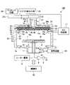
- FIG. 1is a schematic cross-sectional view showing an example of a plasma processing apparatus.
- a microwave plasma processing apparatus 100will be described below as an example of a plasma processing apparatus that executes the film forming method and the cleaning method according to the embodiment.
- the microwave plasma processing apparatus 100 of the present disclosureis an RLSA (registered trademark) microwave plasma processing apparatus.
- a microwave plasma processing apparatusforms a silicon-containing film such as a silicon nitride film (SiN) on a substrate W such as a semiconductor wafer by plasma CVD (Chemical Vapor Deposition).
- the microwave plasma processing apparatus 100has a cylindrical chamber 1 that is hermetically configured and grounded.
- a circular opening 10is formed in a substantially central portion of the bottom wall 1a of the chamber 1, and the bottom wall 1a is provided with an exhaust chamber 11 that communicates with the opening 10 and protrudes downward.
- the inner wall of the chamber 1is made of a metallic material such as aluminum and is thermally sprayed with alumina (Al 2 O 3 ) or yttria (Y 2 O 3 ), for example.
- a stage 2 made of ceramics such as AlNis provided in the chamber 1 for supporting the substrate W horizontally.
- the stage 2is supported by a cylindrical support member 3 made of ceramic such as AlN and extending upward from the center of the bottom of the exhaust chamber 11 .
- a resistance heating type heater 5is embedded in the stage 2 . The heater 5 heats the stage 2 and controls the temperature of the substrate W by being supplied with power from the heater power source 6 .
- An electrode 7is embedded in the stage 2 , and a high-frequency power source 9 for bias application is connected to the electrode 7 through a matching box 8 .
- the stage 2may be provided with an electrostatic chuck for electrostatically attracting the substrate W, a temperature control mechanism, a gas flow path for supplying a heat transfer gas to the rear surface of the substrate W, and the like.
- the stage 2is provided with wafer support pins (not shown) for supporting and lifting the substrate W so as to protrude from the surface of the stage 2 .
- Annular gas introduction portions 15 and 16are provided on the side wall of the chamber 1, and gas emission holes 15a and 16a are equally formed in the gas introduction portions 15 and 16 in the circumferential direction.
- a gas supply unit 17is connected to the gas introduction units 15 and 16 .
- the gas supply unit 17supplies a processing gas for film formation during film formation.
- the gas supply unit 17may introduce a cleaning gas during cleaning.
- the top plate of the chamber 1is made of a dielectric such as alumina (Al 2 O 3 ) and serves as a transmission window 28 that transmits microwaves.
- a microwave power introduction portion 42is provided in the center of the transmission window 28 .
- a processing gas for film formation or a cleaning gasmay be introduced from the gas introduction portion 18 provided around the introduction portion 42 through the gas emission holes 18a.
- An exhaust pipe 23is connected to the side of the exhaust chamber 11, and an exhaust device 24 including a vacuum pump, an automatic pressure control valve, etc. is connected to the exhaust pipe 23.
- an exhaust device 24including a vacuum pump, an automatic pressure control valve, etc. is connected to the exhaust pipe 23.
- An automatic pressure control valvecan control the inside of the chamber 1 to a predetermined degree of vacuum.
- a loading/unloading port 25 for loading/unloading the substrate W to/from a transfer chamber (not shown) adjacent to the microwave plasma processing apparatus 100 and a gate valve 26 for opening/closing the loading/unloading port 25are provided. and are provided.
- the upper part of the chamber 1is an opening, and the peripheral edge of the opening is a ring-shaped support part 27 .
- a disc-shaped transmission window 28is provided in the support portion 27 via a seal member 29 . Thereby, the inside of the chamber 1 is kept airtight.
- a disk-shaped planar antenna 31 corresponding to the transmission window 28is provided on the upper surface of the transmission window 28 .
- a planar antenna 31is locked to the upper end of the side wall of the chamber 1 .
- the planar antenna 31is composed of a disc made of a conductive material, and has a plurality of slots 32 passing through it for radiating microwaves.
- a plurality of pairs of slots 32are arranged concentrically, with two slots 32 arranged in a T shape forming a pair.
- the length and arrangement intervals of the slots 32are determined according to the wavelength ( ⁇ g) of the microwave, and the slots 32 are arranged so that the intervals between them are ⁇ g/4, ⁇ g/2 or ⁇ g, for example.
- the slots 32may have other shapes such as a circular shape and an arc shape.
- the arrangement form of the slots 32is not particularly limited, and they can be arranged concentrically, spirally, or radially, for example.
- a plate-like member 33made of a dielectric material having a dielectric constant greater than that of vacuum, such as resin such as quartz, polytetrafluoroethylene, or polyimide, is provided.
- the plate-shaped member 33has a function of making the wavelength of the microwave shorter than that in a vacuum and reducing the dimensions of the planar antenna 31 .
- the flat antenna 31 and the transmission window 28are in close contact with each other, and the plate member 33 and the flat antenna 31 are also in close contact. Further, the thicknesses of the transmission window 28 and the plate member 33 are adjusted so that an equivalent circuit formed by the plate member 33, the planar antenna 31, the transmission window 28, and the plasma satisfies the resonance condition. By adjusting the thickness of the plate-shaped member 33, the phase of the microwave can be adjusted. is minimized and the microwave radiation energy is maximized. Further, by using the same material for the plate member 33 and the transmissive window 28, it is possible to prevent interface reflection of microwaves.
- a spacemay be provided between the planar antenna 31 and the transmission window 28 and between the plate-like member 33 and the planar antenna 31 .
- a shield lid 34made of a metal material such as aluminum, stainless steel, or copper is provided on the upper surface of the chamber 1 so as to cover the planar antenna 31 and the plate member 33 .
- the upper surface of the chamber 1 and the shield lid 34are sealed by a sealing member 35 .
- a cooling water flow path 34ais formed in the shield lid 34, and the shield lid 34, the plate member 33, the planar antenna 31, and the transmission window 28 are cooled by flowing cooling water through the cooling water flow path 34a. do.
- the shield lid 34is grounded.
- An opening 36is formed in the center of the upper wall of the shield lid 34 , and a waveguide 37 is connected to the opening 36 .
- a microwave output section 39is connected to the end of the waveguide 37 via a matching circuit 38 .
- microwaves having a frequency of 2.45 GHz, for example, generated by the microwave output section 39are propagated to the planar antenna 31 via the waveguide 37 .
- the frequency of the microwavefor example, frequencies in the range of 100 MHz to 2450 MHz can be used.
- the waveguide 37is connected to a coaxial waveguide 37a having a circular cross section extending upward from the opening 36 of the shield lid 34 and the upper end of the coaxial waveguide 37a via a mode converter 40. and a rectangular waveguide 37b extending in the horizontal direction.
- the mode converter 40has a function of converting the microwave propagating in the TE mode in the rectangular waveguide 37b into the TEM mode.
- An internal conductor 41extends through the center of the coaxial waveguide 37 a , and a lower end portion (introduction portion 42 ) of the internal conductor 41 is connected and fixed to the center of the planar antenna 31 . Thereby, the microwaves are uniformly propagated to the planar antenna 31 through the inner conductor 41 of the coaxial waveguide 37a.
- the microwave plasma processing apparatus 100has a control section 50.
- the control unit 50is a CPU that controls each component of the microwave plasma processing apparatus 100, such as the microwave output unit 39, the heater power source 6, the high-frequency power source 9, the exhaust device 24, the valves and flow rate controllers of the gas supply unit 17, and the like. (computer).
- the control unit 50also has an input device (keyboard, mouse, etc.), an output device (printer, etc.), a display device (display, etc.), and a storage device (storage medium).
- the control unit 50causes the microwave plasma processing apparatus 100 to perform the following film formation method based on a processing recipe stored in a storage medium built in a storage device or a storage medium set in the storage device, for example. Let
- the gate valve 26is opened, and the substrate W is loaded into the chamber 1 through the loading/unloading port 25 and placed on the stage 2 .
- the gate valve 26is closed, the inside of the chamber 1 is adjusted to a predetermined pressure, and the processing gas is introduced into the chamber 1 from the gas supply section 17 through the gas introduction sections 15 , 16 and 18 .
- a microwave having a predetermined poweris introduced into the chamber 1 from the microwave output unit 39 to generate plasma, and a SiN film as an example of a Si-containing film is formed on the substrate W by plasma CVD.
- a microwave with a predetermined power from the microwave output section 39is guided to the waveguide 37 through the matching circuit 38 .
- the microwave guided to the waveguide 37propagates in the rectangular waveguide 37b in TE mode.
- the TE mode microwaveis mode-converted to the TEM mode by the mode converter 40, and the TEM mode microwave propagates in the TEM mode through the coaxial waveguide 37a.
- the TEM mode microwaveis transmitted through the plate member 33 , the slot 32 of the planar antenna 31 and the transmission window 28 and radiated into the chamber 1 .
- the surface wave of the microwavespreads in the area directly below the transmission window 28, thereby generating a surface wave plasma that has a high electron density and a low electron temperature.
- active species dissociated from the film forming gasreact on the substrate W to form a predetermined film.
- the film forming process described aboveis performed on a plurality of substrates W one by one, the components of the film formed on the inner walls and parts of the chamber 1 gradually adhere.
- the depositsare deposited and peeled off, they become particles. Since a predetermined number of particles or more causes a decrease in yield, the inside of the chamber 1 is cleaned at predetermined intervals.
- silane gas (SiH 4 ) and N 2 gas, or silane gas and NH 3 gasare supplied as an example of processing gas.
- Microwavesare introduced into the chamber 1 through a transmissive window 28 made of alumina.
- AlF compound containing fluorine contained in the NF 3 gas and aluminum contained in the alumina forming the transmission window 28adheres to the side walls of the chamber 1 after cleaning.
- the AlF compoundis AlF mixed with Si, N, and H, and adheres to the side walls of the chamber 1, etc., as shown in FIG. 2A, and can be represented by AlFx (Si/N/H).
- AlFxAlF compound adheres to the inner side surface of 1 .
- Si and N mixed in the AlF compoundare Si and N in the SiN film, Si substrate or silane gas (SiH 4 ) and N 2 (or NH 3 ) gas.
- the H mixed in the AlF compoundis the H in the SiH4 used as the process gas.
- FIG. 2Ais a diagram showing an example of the composition of deposits on the side walls of the chamber 1, showing an example of the results of analyzing the deposits on the side walls of the chamber 1 by X-ray Photoelectron Spectroscopy (XPS). From this result, the deposit in chamber 1 contains 23.4% Al and 51.8% F, accounting for about 75% of the AlF compound.
- the remaining components of the AlF compoundinclude 11.2% N, 8% O, 4.7% C, 0.6% Si and 0.4% Y.
- the Y component in the AlF compoundwas detected in the coating film coating the inner wall of the chamber 1 with yttria (Y 2 O 3 ). It is considered that the O component in the AlF compound is due to the oxidation of AlF or the detection of O in yttria.
- the C componentsince a carbon tape was used during the XPS analysis, it is considered that C was detected in the tape. Although it is difficult to detect the H component by XPS analysis, it is considered that H is also contained based on past experience.
- the AlF compoundis in an unstable state containing Si, N, and H components compared to the chemically stable state of AlF. For this reason, when argon ions in plasma generated from argon gas, which is a rare gas, collide with the AlF compound, the AlF compound is easily peeled off from the inner wall of the chamber 1, which is considered to be a cause of particle generation.
- modifying an AlF compoundmeans removing Si, N, and H from the AlF compound to form AlF.
- the modification of the AlF compoundincludes reducing the Si, N and H components in the AlF compound, and some Si, N and H may be mixed in the AlF compound.
- FIG. The cleaning method MTincludes a fluorine-containing gas plasma cleaning process and a rare gas and H 2 gas plasma seasoning process, which are performed after SiN films are formed on a predetermined number of substrates W in the film formation process.
- a film forming process, a plasma cleaning process, and a plasma seasoning processare controlled by the controller 50 .
- NF3 gasis used as an example of fluorine-containing gas in the plasma cleaning process, but the fluorine - containing gas is not limited to this and may be ClF3 gas , CF4 gas, or the like.
- the rare gasis not limited to this and may be He gas.
- a SiN filmis formed as an example of a Si-containing film in the film forming process, the SiCN film, SiO 2 film, and SiC film may be formed.
- FIG. 3is a flow chart showing the film formation and cleaning method MT according to the embodiment.
- the substrate Wis loaded into the chamber 1 and placed on the stage 2 for preparation.
- silane (SiH 4 ) gas and nitrogen (N 2 ) gas as processing gasesare supplied into the chamber 1, and microwaves are introduced.
- nitrogen gasis supplied into the chamber 1 through the gas emission holes 18a
- silane gasis supplied into the chamber 1 through the gas emission holes 15a and 16a.
- Microwavesare introduced into chamber 1 through transmissive window 28 .
- step S6the substrate W after film formation is unloaded from the chamber 1. Next, as shown in FIG.
- step S7it is determined whether cleaning is to be performed. Whether or not cleaning is to be performed may be determined to be performed, for example, when the cumulative time of the film formation process or the cumulative time of applying microwaves reaches a predetermined time or longer.
- the thickness of deposits on the inner wall of the chamber 1may be measured, and when the thickness reaches a predetermined thickness or more, it may be determined that cleaning should be performed.
- step S7If it is determined in step S7 that cleaning is not to be performed, the process returns to step S1, and film formation processing for the next substrate W is performed. Steps S1 to S7 are repeated to form a SiN film on each substrate W until it is determined in step S7 that cleaning is to be performed.
- step S7If it is determined in step S7 that cleaning is to be performed, plasma of NF 3 gas is generated by microwaves in step S11, and the inside of the chamber 1 is cleaned by the plasma.
- step S15the seasoning method is executed in step S15. Details of the seasoning method will be described later with reference to FIG.
- step S17After executing the seasoning in step S15, it is determined in step S17 whether to end the processing of the substrate W. If it is determined not to end the processing of the substrate W, the process returns to step S1, and the film formation processing of the next substrate W is performed. to resume. If it is determined to end the processing of the substrate W, this processing ends.
- the seasoning in step S15may be performed immediately after the plasma cleaning in step S11 as in the above flow, or may be performed at an arbitrary timing such as when an increase in particles is confirmed after the film formation process is restarted. you can go
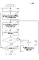
- FIG. 4shows the flow of the seasoning method MT2 according to the embodiment.
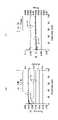
- FIG. 5shows supply timings of Ar gas, H 2 gas and microwave in the seasoning method MT2 shown in FIG.
- step S201 is set to the number of executions n of the "series of steps".
- a series of stepsshows one cycle of performing seasoning by changing the concentration of H 2 gas with respect to Ar gas to a first concentration, a second concentration, and a third concentration, which are all different concentrations.
- step S 21the flow rate of Ar gas or H 2 gas is controlled so that the concentration of H 2 gas with respect to Ar gas becomes the first concentration, and supplied into the chamber 1 .
- step S23microwaves are introduced into the chamber 1, and the AlF compound adhering to the inner wall of the chamber 1 is reformed by the plasma of the first concentration Ar gas and H2 gas generated by the microwaves.
- T2T2 ( T2>T1).
- the first concentrationis B/A1.
- step S24the supply of Ar gas, H2 gas and microwaves is stopped after a predetermined time has elapsed. That is, as shown in FIG . 5, the supply of Ar gas, H2 gas and microwaves is stopped at time T3.
- the second concentration of H 2 gas and Ar gasis supplied into the chamber 1, and the plasma of the second concentration of Ar gas and H 2 gas generated by microwaves is applied to the inner wall of the chamber 1 and the like. Modifies the attached AlF compound. For example, as shown in FIG.
- Ar gas with a flow rate of A2(A2>A1) is supplied at time T4, microwaves are introduced at time T5 (T5>T4), and flow rate B is introduced at time T6 (T6>T5). H2 gas is supplied.
- the second densityis B/A2, and the first density>second density holds.
- step S24the supply of Ar gas, H2 gas and microwaves is stopped after a predetermined time has elapsed. That is, as shown in FIG . 5, the supply of Ar gas, H2 gas and microwaves is stopped at time T7.
- step S23the third concentration H 2 gas and Ar gas are supplied into the chamber 1, and the plasma of the third concentration Ar gas and H 2 gas generated by the microwaves is applied to the inner wall of the chamber 1 and the like. Modifies the attached AlF compound. For example, as shown in FIG.
- Ar gas with a flow rate of A3(A3>A2) is supplied at time T8, microwaves are introduced at time T9 (T9>T8), and flow rate B is introduced at time T10 (T10>T9). H2 gas is supplied.
- the third densityis B/A3, and the relationship of first density>second density>third density is established.
- step S24the supply of Ar gas, H2 gas and microwaves is stopped after a predetermined time has elapsed. That is, as shown in FIG . 5, the supply of Ar gas, H2 gas and microwaves is stopped at time T11.
- step S25it is determined whether the number of executions n is 3 or more. Since n is 3 at this point, it is determined as "Yes", and it is determined in step S28 whether the cycle has been repeated a preset number of times. Returning to step S20, the "series of steps" shown in steps S20 to S27 are repeated until it is determined that the number of cycles has been repeated. If it is determined in step S28 that the process has been repeated for the number of cycles, the seasoning process ends.
- step S28 of FIG. 4the seasoning of the first density to the third density is repeated for the number of cycles.
- An experimentwas conducted on the optimum value of the number of cycles.
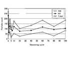
- FIG. 6is a graph of experimental results showing an example of the correlation between the number of cycles in S28 of FIG. 4 and the number of particles.
- the experimental conditionsare as follows. ⁇ Experimental conditions> 1. First concentration 5.6 H2 gas 280 sccm, Ar gas 50 sccm, pressure 4 Pa, Microwave power 4500W, seasoning time 60s 2. Second concentration 2.8 H2 gas 280 sccm, Ar gas 100 sccm, pressure 4 Pa, Microwave power 4500W, seasoning time 60s 3.
- third concentration 1.4 H2 gas 280 sccm, Ar gas 200 sccm, pressure 4 Pa, Microwave power 4500W, seasoning time 60s 4 Pais the pressure inside the chamber 1, and the damage to the chamber 1 can be reduced by lowering the pressure.
- 60 sis the seasoning time for each concentration, which is the time from the first supply of Ar gas until the supply of each gas is stopped.
- the horizontal axis in FIG. 6indicates the number of seasoning cycles, and the vertical axis indicates the number of particles. From the experimental results shown in FIG. 6, it was found that the total number of particles, which is the sum of SiN and AlF particles, decreased to about 100 when the number of cycles was about 5. Even if the number of cycles is 6 or more, the total number of particles is at least about 100, which is not much different from 5 times. For this reason, the number of cycles may be five or more, but the longer the number of cycles, the longer the cleaning time including seasoning, and the lower the throughput. Therefore, it was found that it is preferable to set the number of cycles to 5 so that the seasoning time is the shortest and the effect of reducing the number of particles to about 100 can be obtained.
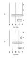
- FIG. 7is a graph showing an example of the modification result of deposits by the seasoning method MT2 according to the embodiment.
- FIG. 7(a)shows an example of the result of analyzing deposits on the side wall of the chamber 1 by X-ray photoelectron spectroscopy before executing the seasoning method MT2.
- the horizontal axis of FIG. 7Aindicates the names of the elements constituting the AlF compound, and the vertical axis indicates the ratio thereof. From this result, the deposit in the chamber 1 before executing the seasoning method MT2 was in the state of an AlF compound containing Si and N in AlF.
- FIG. 7(b)shows an example of the result of analyzing deposits on the side wall of the chamber 1 after executing the seasoning method MT2 by X-ray photoelectron spectroscopy.
- the horizontal axis of FIG. 7(b)indicates the names of the elements constituting the AlF compound, and the vertical axis indicates the ratio thereof.
- the seasoning method MT2is not limited to changing the concentration of H 2 gas with respect to Ar gas by fixing the flow rate of H 2 gas and changing the flow rate of Ar gas.
- the flow rate of Ar gasmay be fixed and the flow rate of H2 gas may be changed to change the concentration of H2 gas relative to Ar gas, or the concentration may be changed by changing the flow rates of both gases.
- hydrogen plasma in a state suitable for various AlF compounds with different amounts of Si, N, and H adhering to themcan be generated by changing the H2 concentration, and various AlF compounds can be stabilized to AlF. be able to.
- the AlF compoundcan be reformed into AlF even if Si, N, and H adhere to different locations and are mixed in different amounts.
- the cleaning method MTincludes a step of performing cleaning with plasma of fluorine-containing gas, and a step of performing seasoning with plasma of noble gas and H 2 gas after cleaning.
- the step of performing seasoningincludes a first step in which the concentration of H2 gas with respect to the rare gas is the first concentration, and a step in which the concentration of H2 gas with respect to the rare gas is different from the first concentration.
- a second step with a second concentration and a third step with a third concentration different from the first and second concentrationsare provided, and a series of steps including the first to third steps are repeated multiple times. The number of times may be 5 times or more, but 5 times is preferable.
- the first density, the second density, and the third densitymay all be different, and the density may be decreased stepwise, the density may be increased stepwise, or the density may be increased or decreased. You may
- the concentration of H 2 gas with respect to Ar gasis controlled in three stages from the first concentration to the third concentration, but the present invention is not limited to this.
- the concentration of H2 gas with respect to Ar gasmay be controlled in two stages or four stages or more.
- the step of performing seasoningincludes a first step in which the concentration of H 2 gas with respect to the rare gas is the first concentration, and a second step in which the concentration of H 2 gas with respect to the rare gas is a second concentration different from the first concentration. and a series of steps including the first step and the second step may be repeated multiple times.
- the first to third concentrationswere 1.4 to 5.6, but the present invention is not limited to this.
- the concentration of H2 gas with respect to Ar gasmay be 0.1 or more and 10 or less.
- FIG. 8is a graph showing an example of the result of film formation performed after executing the seasoning method MT2.
- FIG. 8(a)shows an example of the measurement result of the film thickness of the film formed after executing the seasoning method MT2.
- FIG. 8Bshows an example of measurement results of RI (refractive index) of film formed after execution of the seasoning method MT2.
- the film thickness of the SiN film shown in FIG. 8(a)indicates an average value obtained by measuring the film thickness at 49 points within the wafer surface.
- R/A [%]indicates a value obtained by dividing the difference between the maximum value and the minimum value of the film thickness at 49 points in the plane of the wafer by the average value. That is, R/A indicates the film thickness distribution.
- the film thickness on the left vertical axis and the film thickness distribution (R/A) on the right vertical axisdid not change with the number of cycles of seasoning on the horizontal axis of FIG. It was also found that there is no adverse effect on the film formation process.
- the RI of the SiN film shown in FIG. 8(b)indicates the average value of the RI measured at 49 points in the plane of the wafer. Range indicates the difference between the maximum value and the minimum value of RI at 49 points in the plane of the wafer. Range indicates the RI distribution. With respect to the number of seasoning cycles on the horizontal axis of FIG. 8B, there is no change in the RI distribution (Range) on the left vertical axis and the RI distribution (Range) on the right vertical axis. was found to have no adverse effect on
- FIG. 9is a graph of experimental results showing an example of the correlation between the number of cycles and the number of particles according to the embodiment and the reference example.
- a line gindicates the number of particles on the vertical axis with respect to the number of cycles 1, 5, and 10 on the horizontal axis when the seasoning method MT2 of the present embodiment is executed under the ⁇ experimental conditions> when the experiment in FIG. 6 was performed.
- Lines e and fshow the number of particles for cycles 1, 5 and 10 when the flow rates of Ar gas and H2 gas are fixed as shown in Reference Examples 1 and 2.
- the flow rates of Ar gas and H2 gaswere fixed at 200 sccm and 280 sccm, respectively, and this was defined as one cycle.
- the flow rates of Ar gas and H2 gasare set to three concentrations of (1) 50 sccm, 280 sccm, (2) 100 sccm, 280 sccm, and (3) 200 sccm, 280 sccm. This was regarded as one cycle.
- the seasoning method MT2 of the present embodimentby changing the concentration of H2 gas to Ar gas in three stages, hydrogen plasma in a state suitable for various AlF compounds having different amounts of Si, N, and H mixed and adhesion locations is generated. , could be generated by varying the H2 concentration, and various AlF compounds could be modified to AlF. As a result, as indicated by line g, the number of particles counted could be reduced when the number of cycles was 5 or more.
- the concentration of H 2 gas with respect to Ar gasis changed in two or more stages.
- various AlF compounds with different amounts of Si, N, and H mixed and where they adherecan be reformed into stable AlF.
- particlescan be reduced, and productivity can be improved by lengthening the maintenance cycle.
- the plasma processing apparatus of the present disclosurecan be applied to any type of apparatus as long as it introduces microwaves into the chamber through a transmissive window made of alumina and processes a substrate with plasma of a processing gas.
Landscapes
- Chemical & Material Sciences (AREA)
- Engineering & Computer Science (AREA)
- Metallurgy (AREA)
- Organic Chemistry (AREA)
- General Chemical & Material Sciences (AREA)
- Chemical Kinetics & Catalysis (AREA)
- Materials Engineering (AREA)
- Mechanical Engineering (AREA)
- Physics & Mathematics (AREA)
- Plasma & Fusion (AREA)
- Condensed Matter Physics & Semiconductors (AREA)
- General Physics & Mathematics (AREA)
- Manufacturing & Machinery (AREA)
- Computer Hardware Design (AREA)
- Microelectronics & Electronic Packaging (AREA)
- Power Engineering (AREA)
- Chemical Vapour Deposition (AREA)
Abstract
Description
Translated fromJapanese本開示は、クリーニング方法及びプラズマ処理装置に関する。The present disclosure relates to a cleaning method and a plasma processing apparatus.
例えば、特許文献1は、マイクロ波プラズマにより基板を処理するチャンバのクリーニング方法を提案する。特許文献1では、フッ素含有ガス、アルゴンガス及びヘリウムガスを含むクリーニングガスを導入する工程と、マイクロ波パワーを供給する工程と、を有し、前記クリーニングガスを導入する工程は、アルゴンガスに対するヘリウムガスの流量比を2/3~9の範囲内にする。For example,
本開示は、パーティクルを低減できる技術を提供する。The present disclosure provides technology that can reduce particles.
本開示の一の態様によれば、透過窓を介してマイクロ波をチャンバ内に導入し、処理ガスのプラズマにより基板に対して処理を行うプラズマ処理装置のクリーニング方法であって、前記クリーニング方法は、フッ素含有ガスのプラズマによるクリーニングを行う工程と、前記クリーニングを行った後に希ガスとH2ガスのプラズマによるシーズニングを行う工程と、を有し、前記シーズニングを行う工程は、前記希ガスに対する前記H2ガスの濃度が第1濃度である第1工程と、前記希ガスに対する前記H2ガスの濃度が前記第1濃度と異なる第2濃度である第2工程と、を有し、前記第1工程と前記第2工程を含む一連の工程を複数回繰り返すクリーニング方法が提供される。According to one aspect of the present disclosure, there is provided a cleaning method for a plasma processing apparatus in which microwaves are introduced into a chamber through a transmission window and a substrate is processed by plasma of a processing gas, the cleaning method comprising: a step of performing cleaning with plasma of a fluorine- containing gas; and a step of performing seasoning with plasma of a rare gas and H2 gas after performing the cleaning, wherein the step of performing the seasoning is performed by removing the a first step in which the concentration of the H2 gas is a first concentration; and asecond step in which the concentration of the H2 gas with respect to the rare gas is asecond concentration different from the first concentration; A cleaning method is provided in which a series of steps including the step and the second step are repeated multiple times.
一の側面によれば、パーティクルを低減できる。According to one aspect, particles can be reduced.
以下、図面を参照して本開示を実施するための形態について説明する。各図面において、同一構成部分には同一符号を付し、重複した説明を省略する場合がある。Embodiments for carrying out the present disclosure will be described below with reference to the drawings. In each drawing, the same components are denoted by the same reference numerals, and redundant description may be omitted.
[プラズマ処理装置]
実施形態に係るプラズマ処理装置について、図1を用いて説明する。図1は、プラズマ処理装置の一例を示す断面模式図である。以下では、実施形態に係る成膜方法及びクリーニング方法を実行するプラズマ処理装置の一例としてマイクロ波プラズマ処理装置100を挙げて説明する。本開示のマイクロ波プラズマ処理装置100は、RLSA(登録商標)マイクロ波プラズマ処理装置である。マイクロ波プラズマ処理装置は、半導体ウェハ等の基板WにプラズマCVD(Chemical Vapor Deposition)により例えばシリコン窒化膜(SiN)等のシリコン含有膜を成膜する。[Plasma processing equipment]
A plasma processing apparatus according to an embodiment will be described with reference to FIG. FIG. 1 is a schematic cross-sectional view showing an example of a plasma processing apparatus. A microwave
マイクロ波プラズマ処理装置100は、気密に構成され、接地された円筒状のチャンバ1を有している。チャンバ1の底壁1aの略中央部には円形の開口部10が形成されており、底壁1aには開口部10と連通し、下方に向けて突出する排気室11が設けられている。The microwave
チャンバ1の内壁は、アルミニウム等の金属材料に例えばアルミナ(Al2O3)又はイットリア(Y2O3)の溶射が施されている。チャンバ1内には基板Wを水平に支持するためのAlN等のセラミックスからなるステージ2が設けられている。ステージ2は、排気室11の底部中央から上方に延びる円筒状のAlN等のセラミックスからなる支持部材3により支持されている。また、ステージ2には抵抗加熱型のヒーター5が埋め込まれている。ヒーター5はヒーター電源6から給電されることによりステージ2を加熱し基板Wを温調する。また、ステージ2には電極7が埋め込まれており、電極7には整合器8を介してバイアス印加用の高周波電源9が接続されている。ステージ2には、基板Wを静電吸着するための静電チャック、温度制御機構、基板Wの裏面に熱伝達用のガスを供給するガス流路等が設けられてもよい。The inner wall of the
ステージ2には、基板Wを支持して昇降させるためのウェハ支持ピン(不図示)がステージ2の表面に対して突没可能に設けられている。チャンバ1の側壁には環状をなすガス導入部15、16が設けられており、ガス導入部15、16には周方向に均等にガス放射孔15a、16aが形成されている。ガス導入部15、16にはガス供給部17が接続されている。ガス供給部17は、成膜時には成膜用の処理ガスを供給する。ガス供給部17は、クリーニング時にはクリーニングガスを導入してもよい。The
チャンバ1の天板は、誘電体、例えばアルミナ(Al2O3)により形成され、マイクロ波を透過させる透過窓28になっている。透過窓28の中央にはマイクロ波パワーの導入部42が設けられている。導入部42の周囲に設けられたガス導入部18からガス放射孔18aを介して成膜用の処理ガスやクリーニングガスを導入してもよい。The top plate of the
排気室11の側面には排気管23が接続され、排気管23には真空ポンプや自動圧力制御バルブ等を含む排気装置24が接続されている。排気装置24の真空ポンプを作動させることによりチャンバ1内のガスが、排気室11の空間11a内へ均一に排出され、排気管23を介して排気される。自動圧力制御バルブによりチャンバ1内を所定の真空度に制御可能となっている。An
チャンバ1の側壁には、マイクロ波プラズマ処理装置100に隣接する搬送室(図示せず)との間で基板Wの搬入出を行うための搬入出口25と、搬入出口25を開閉するゲートバルブ26とが設けられている。On the side wall of the
チャンバ1の上部は開口部となっており、その開口部の周縁部がリング状の支持部27となっている。支持部27には円板状の透過窓28がシール部材29を介して設けられている。これにより、チャンバ1内は気密に保持される。透過窓28の上面には、透過窓28に対応する円板状をなす平面アンテナ31が設けられている。平面アンテナ31はチャンバ1の側壁上端に係止されている。The upper part of the
平面アンテナ31は、導電性材料からなる円板で構成され、マイクロ波を放射するための複数のスロット32が貫通している。スロット32のパターンの例としては、T字状に配置された2つのスロット32を一対として複数対のスロット32が同心円状に配置されているものを挙げることができる。スロット32の長さや配列間隔は、マイクロ波の波長(λg)に応じて決定され、例えばスロット32は、それらの間隔がλg/4、λg/2またはλgとなるように配置される。なお、スロット32は、円形状、円弧状等の他の形状であってもよい。さらに、スロット32の配置形態は特に限定されず、同心円状のほか、例えば、螺旋状、放射状に配置することもできる。The
平面アンテナ31の上面には、真空よりも大きい誘電率を有する誘電体、例えば石英、ポリテトラフルオロエチレン、ポリイミドなどの樹脂からなる板状部材33が設けられている。板状部材33はマイクロ波の波長を真空中より短くして平面アンテナ31の寸法を小さくする機能を有している。On the upper surface of the
平面アンテナ31と透過窓28との間が密着した状態となっており、また、板状部材33と平面アンテナ31との間も密着されている。また、板状部材33、平面アンテナ31、透過窓28、およびプラズマで形成される等価回路が共振条件を満たすように透過窓28、板状部材33の厚さが調整されている。板状部材33の厚さを調整することにより、マイクロ波の位相を調整することができ、平面アンテナ31との接合部が定在波の「はら」になるようにすることでマイクロ波の反射が極小化され、マイクロ波の放射エネルギーが最大となる。また、板状部材33と透過窓28を同じ材質とすることにより、マイクロ波の界面反射を防止することができる。The
なお、平面アンテナ31と透過窓28との間、また、板状部材33と平面アンテナ31との間は、離間していてもよい。チャンバ1の上面には、平面アンテナ31および板状部材33を覆うように、例えばアルミニウムやステンレス鋼、銅等の金属材料からなるシールド蓋体34が設けられている。チャンバ1の上面とシールド蓋体34とはシール部材35によりシールされている。シールド蓋体34には、冷却水流路34aが形成されており、冷却水流路34aに冷却水を通流させることにより、シールド蓋体34、板状部材33、平面アンテナ31、透過窓28を冷却する。シールド蓋体34は接地されている。A space may be provided between the
シールド蓋体34の上壁の中央には開口部36が形成されており、開口部36には導波管37が接続されている。導波管37の端部には、マッチング回路38を介してマイクロ波出力部39が接続されている。これにより、マイクロ波出力部39で発生した例えば周波数2.45GHzのマイクロ波が導波管37を介して平面アンテナ31へ伝搬される。なお、マイクロ波の周波数としては、例えば100M~2450MHzの範囲の周波数を用いることができる。An
導波管37は、シールド蓋体34の開口部36から上方へ延在する断面円形状の同軸導波管37aと、同軸導波管37aの上端部にモード変換器40を介して接続された水平方向に延びる矩形導波管37bとを有している。モード変換器40は、矩形導波管37b内をTEモードで伝搬するマイクロ波をTEMモードに変換する機能を有している。同軸導波管37aの中心には内部導体41が延在しており、内部導体41の下端部(導入部42)は、平面アンテナ31の中心に接続固定されている。これにより、マイクロ波は、同軸導波管37aの内部導体41を介して平面アンテナ31へ均一に伝搬される。The
マイクロ波プラズマ処理装置100は制御部50を有している。制御部50は、マイクロ波プラズマ処理装置100の各構成部、例えばマイクロ波出力部39、ヒーター電源6、高周波電源9、排気装置24、ガス供給部17のバルブや流量制御器等を制御するCPU(コンピュータ)を有する。また、制御部50は、入力装置(キーボード、マウス等)、出力装置(プリンタ等)、表示装置(ディスプレイ等)及び記憶装置(記憶媒体)を有する。制御部50は、例えば、記憶装置に内蔵された記憶媒体、または記憶装置にセットされた記憶媒体に記憶された処理レシピに基づいて、マイクロ波プラズマ処理装置100に、以下の成膜方法を実行させる。The microwave
かかる構成のマイクロ波プラズマ処理装置100を用いた成膜方法の一実施形態について説明する。まず、ゲートバルブ26を開き、搬入出口25から基板Wをチャンバ1内に搬入し、ステージ2上に載置する。次いで、ゲートバルブ26を閉じ、チャンバ1内を所定圧力に調整し、ガス供給部17からガス導入部15、16、18を介してチャンバ1内に処理ガスを導入する。そして、マイクロ波出力部39から所定パワーのマイクロ波をチャンバ1内に導入してプラズマを生成し、プラズマCVDにより基板W上にSi含有膜の一例としてSiN膜を成膜する。An embodiment of a film forming method using the microwave
マイクロ波出力部39からの所定のパワーのマイクロ波は、マッチング回路38を経て導波管37に導かれる。導波管37に導かれたマイクロ波は、矩形導波管37bをTEモードで伝搬される。TEモードのマイクロ波はモード変換器40でTEMモードにモード変換され、TEMモードのマイクロ波が同軸導波管37aをTEMモードで伝搬される。そして、TEMモードのマイクロ波は、板状部材33、平面アンテナ31のスロット32、および透過窓28を透過し、チャンバ1内に放射される。A microwave with a predetermined power from the
マイクロ波の表面波は、透過窓28直下の領域に広がり、これにより表面波プラズマが生成され、高電子密度かつ低電子温度のプラズマとなる。これにより、成膜ガスから解離された活性種が基板W上で反応して所定膜が成膜される。The surface wave of the microwave spreads in the area directly below the
以上に説明した成膜処理を複数枚の基板Wに一枚ずつ実行していくと、徐々にチャンバ1の内壁やパーツに成膜した膜の成分等が付着する。その付着物が堆積して剥がれるとパーティクルとなる。所定個数以上のパーティクルは歩留まり低下の要因となるため、所定周期でチャンバ1内をクリーニングすることが行われている。When the film forming process described above is performed on a plurality of substrates W one by one, the components of the film formed on the inner walls and parts of the
SiN膜を成膜する場合、処理ガスの一例としてシランガス(SiH4)及びN2ガス、又はシランガス及びNH3ガス等が供給される。マイクロ波は、アルミナ製の透過窓28を介してチャンバ1内に導入される。When forming a SiN film, silane gas (SiH4 ) and N2 gas, or silane gas and NH3 gas are supplied as an example of processing gas. Microwaves are introduced into the
所定周期でチャンバ1内をクリーニングする際、例えばNF3ガスのプラズマが使用される。よって、クリーニング後のチャンバ1の側壁等には、NF3ガスに含まれるフッ素と透過窓28を形成するアルミナ中のアルミニウムを含むAlF化合物が付着する。AlF化合物は、AlFにSi、N及びHが混入したものであり、図2Aに示すようにチャンバ1の側壁等に付着し、AlFx(Si/N/H)で示すことができる。When cleaning the inside of the
クリーニングガスとして使用するNF3ガスから生成されるプラズマ中のフッ素ラジカルと、チャンバ1の透過窓28を形成するアルミナ(Al2O3)とが化学反応することで、透過窓28の内面やチャンバ1内の側面には、AlF化合物(AlFx)が付着する。AlF化合物に混入するSi及びNはSiN膜、Si基板又はシランガス(SiH4)及びN2(又はNH3)ガス中のSi及びNである。AlF化合物に混入するHは、処理ガスとして使用するSiH4中のHである。A chemical reaction between fluorine radicals in the plasma generated from the NF3 gas used as the cleaning gas and alumina (Al2 O3 ) forming the
特に、マイクロ波の表面波プラズマでは、図2Aに示すようにプラズマが強い透過窓28の表面やチャンバ1内の上部側壁においてAlF化合物が多く付着する。AlF化合物はSiやNの不純物を含み、化学的に安定しない。図2Bは、チャンバ1側壁の付着物の組成例を示す図であり、チャンバ1側壁の付着物をX線光電子分光法(XPS:X-ray Photoelectron Spectroscopy)により分析した結果の一例を示す。この結果から、チャンバ1内の付着物には、Alが23.4%、Fが51.8%含まれ、AlF化合物の約75%を占める。AlF化合物の残りの成分には、Nが11.2%、Oが8%、Cが4.7%、Siが0.6%、Yが0.4%含まれる。AlF化合物中のY成分は、チャンバ1内壁をイットリア(Y2O3)でコーティングしているコーティング膜中のYが検出されたと考えられる。AlF化合物中のO成分はAlFが酸化しているため又はイットリア中のOが検出されたと考えられる。C成分は、XPS分析時にカーボンテープを使用しているため、テープ内のCが検出されたと考えられる。なお、XPS分析上、H成分の検出は困難であるが、これまでの経験上Hも含んでいると考えられる。In particular, in the microwave surface wave plasma, as shown in FIG. 2A, a large amount of AlF compound adheres to the surface of the
このようにAlF化合物は、化学的に安定したAlFの状態と比べて、Si、N及びH成分を含み不安定な状態である。このため、AlF化合物に例えば希ガスのアルゴンガスから生成されるプラズマ中のアルゴンイオンが衝突すると、チャンバ1内壁から剥がれ易く、パーティクルの発生要因となると考えられる。Thus, the AlF compound is in an unstable state containing Si, N, and H components compared to the chemically stable state of AlF. For this reason, when argon ions in plasma generated from argon gas, which is a rare gas, collide with the AlF compound, the AlF compound is easily peeled off from the inner wall of the
そこで、クリーニング後のチャンバ1の側壁等に付着したAlF化合物を安定化させる方法として、本実施形態に係るシーズニングでは、希ガスの一例としてのアルゴンガスと水素(H2)ガスのプラズマを発生させ、これにより水素のラジカルを発生させる。そして、プラズマ中の水素ラジカル(H*)によってAlF化合物を還元する。具体的には、以下の化学反応(1)により化学的に不安定なAlF化合物(Si/N/H)の状態から安定したAlFの状態に改質し、Si、N及びH成分はNH*及びSiH*の状態にして揮発させて排気する。
AlFx(Si/N/H)+Ar*+H*→AlF+Al+NH*+SiH*・・(1)Therefore, as a method for stabilizing the AlF compound adhering to the side wall of the
AlFx(Si/N/H)+Ar* +H* →AlF+Al+NH* +SiH* (1)
これにより、本実施形態に係るシーズニングでは、パーティクルの発生要因となるAlFx(Si/N/H)という不安定な状態をAlFという安定した状態にすることでAlFがチャンバ内壁から剥がれ難くなり、パーティクルを低減できる。これにより、メンテナンスの間隔を長くし、プラズマ処理装置の稼働率を上げ、生産性を向上させることができる。本明細書においてAlF化合物の改質とは、AlF化合物からSi、N及びHを除去しAlFの状態にすることをいう。ただし、AlF化合物内のSi、N及びHの成分を減少させることもAlF化合物の改質に含み、AlFには多少のSi、N及びHが混入してもよい。As a result, in the seasoning according to the present embodiment, the unstable state of AlFx (Si/N/H), which is the cause of particle generation, is changed to the stable state of AlF. can be reduced. As a result, maintenance intervals can be lengthened, the operating rate of the plasma processing apparatus can be increased, and productivity can be improved. In the present specification, modifying an AlF compound means removing Si, N, and H from the AlF compound to form AlF. However, the modification of the AlF compound includes reducing the Si, N and H components in the AlF compound, and some Si, N and H may be mixed in the AlF compound.
[クリーニング方法]
次に、マイクロ波プラズマ処理装置100にて実行される成膜及びクリーニング方法について、図3~図5を参照しながら説明する。クリーニング方法MTは、成膜工程において所定枚数の基板WにSiN膜を成膜した後に行われるフッ素含有ガスのプラズマクリーニング工程と希ガスとH2ガスのプラズマシーズニング工程とを含む。成膜工程、プラズマクリーニング工程、プラズマシーズニング工程は制御部50により制御される。以下では、プラズマクリーニング工程においてフッ素含有ガスの一例としてNF3ガスを使用するが、これに限らず、フッ素含有ガスはClF3ガス、CF4ガス等であってもよい。また、プラズマシーズニング工程において希ガスの一例としてArガスを使用するが、これに限らず、希ガスはHeガスであってもよい。また、成膜工程においてSi含有膜の一例としてSiN膜を成膜するが、これに限らず、SiCN膜、SiO2膜、SiC膜を成膜してもよい。[Cleaning method]
Next, a film formation and cleaning method performed by the microwave
図3は、実施形態に係る成膜及びクリーニング方法MTを示すフローチャートである。図3に示す成膜及びクリーニング方法MTは、まず、ステップS1において基板Wをチャンバ1内に搬入し、ステージ2に載置して準備する。次に、ステップS3において処理ガスのシラン(SiH4)ガスと窒素(N2)ガスをチャンバ1内に供給し、マイクロ波を導入する。一例としては、ガス放射孔18aから窒素ガスをチャンバ1内に供給し、ガス放射孔15a、16aかシランガスをチャンバ1内に供給する。マイクロ波は、透過窓28を介してチャンバ1内に導入される。FIG. 3 is a flow chart showing the film formation and cleaning method MT according to the embodiment. In the film formation and cleaning method MT shown in FIG. 3, first, in step S1, the substrate W is loaded into the
次に、ステップS5において生成したシランガスと窒素ガスのプラズマにより基板WにSiN膜を成膜する。次に、ステップS6において成膜後の基板Wをチャンバ1から搬出する。Next, a SiN film is formed on the substrate W by plasma of silane gas and nitrogen gas generated in step S5. Next, in step S6, the substrate W after film formation is unloaded from the
次に、ステップS7においてクリーニングを実行するかを判定する。クリーニングを実行するか否かは、例えば、成膜工程の累積時間又はマイクロ波投入の累積時間が所定時間以上になったらクリーニングを行うと判定してもよい。チャンバ1内壁の付着物の厚みを測定し、厚みが所定の厚さ以上になったらクリーニングを行うと判定してもよい。Next, in step S7, it is determined whether cleaning is to be performed. Whether or not cleaning is to be performed may be determined to be performed, for example, when the cumulative time of the film formation process or the cumulative time of applying microwaves reaches a predetermined time or longer. The thickness of deposits on the inner wall of the
ステップS7においてクリーニングを実行しないと判定された場合、ステップS1に戻り、次の基板Wの成膜処理を実行する。ステップS7においてクリーニングを実行すると判定されるまで、ステップS1~S7の処理を繰り返し、各基板WにSiN膜を成膜する。If it is determined in step S7 that cleaning is not to be performed, the process returns to step S1, and film formation processing for the next substrate W is performed. Steps S1 to S7 are repeated to form a SiN film on each substrate W until it is determined in step S7 that cleaning is to be performed.
ステップS7においてクリーニングを実行すると判定された場合、ステップS11においてマイクロ波によりNF3ガスのプラズマを生成し、プラズマによりチャンバ1内をクリーニングする。次に、ステップS15においてシーズニング方法を実行する。シーズニング方法の詳細については、図4を参照しながら後述する。If it is determined in step S7 that cleaning is to be performed, plasma of NF3 gas is generated by microwaves in step S11, and the inside of the
ステップS15のシーズニングを実行した後、ステップS17において基板Wの処理を終了するかを判定し、基板Wの処理を終了しないと判定された場合、ステップS1に戻り、次の基板Wの成膜処理を再開する。基板Wの処理を終了すると判定された場合、本処理を終了する。なお、ステップS15のシーズニングは、上記フローのように、ステップS11のプラズマによるクリーニングの直後に行ってもよいし、成膜処理の再開後、パーティクルの増加が確認されたタイミング等、任意のタイミングで行ってもよい。After executing the seasoning in step S15, it is determined in step S17 whether to end the processing of the substrate W. If it is determined not to end the processing of the substrate W, the process returns to step S1, and the film formation processing of the next substrate W is performed. to resume. If it is determined to end the processing of the substrate W, this processing ends. Note that the seasoning in step S15 may be performed immediately after the plasma cleaning in step S11 as in the above flow, or may be performed at an arbitrary timing such as when an increase in particles is confirmed after the film formation process is restarted. you can go
[シーズニング方法]
図3のステップS15のシーズニング方法の詳細について、図4及び図5を参照しながら説明する。図4に示すシーズニング方法MT2は、図3のステップS15から呼び出され、実行される。図4は、実施形態に係るシーズニング方法MT2の流れを示す。図5は、図4に示すシーズニング方法MT2におけるArガス、H2ガス及びマイクロ波の供給タイミングを示す。[Seasoning method]
Details of the seasoning method in step S15 of FIG. 3 will be described with reference to FIGS. 4 and 5. FIG. The seasoning method MT2 shown in FIG. 4 is called from step S15 in FIG. 3 and executed. FIG. 4 shows the flow of the seasoning method MT2 according to the embodiment. FIG. 5 shows supply timings of Ar gas, H2 gas and microwave in the seasoning method MT2 shown in FIG.
図4に示すように、シーズニング方法MT2は、まずステップS20において「一連の工程」の実行回数nに1を設定する。一連の工程は、Arガスに対するH2ガスの濃度をいずれも異なる濃度である第1濃度、第2濃度、第3濃度に変えてシーズニングを行う1サイクルを示す。As shown in FIG. 4, in the seasoning method MT2, first, in step S20, 1 is set to the number of executions n of the "series of steps". A series of steps shows one cycle of performing seasoning by changing the concentration of H2 gas with respect to Ar gas to a first concentration, a second concentration, and a third concentration, which are all different concentrations.
具体的にはステップS21においてArガスに対するH2ガスの濃度が第1濃度になるようにArガス又はH2ガスの流量を制御し、チャンバ1内に供給する。次に、ステップS23においてチャンバ1内にマイクロ波を導入し、マイクロ波により生成した第1濃度のArガス及びH2ガスのプラズマによりチャンバ1内壁に付着したAlF化合物を改質する。Arガス、H2ガス及びマイクロ波の供給タイミングの一例としては、図5に示すようにT0時刻に流量A1のArガスが供給され、T1時刻(T1>T0)にマイクロ波のパワーが導入され、T2時刻(T2>T1)に流量BのH2ガスが供給される。第1濃度はB/A1である。Specifically, in step S 21 , the flow rate of Ar gas or H2 gas is controlled so that the concentration of H2 gas with respect to Ar gas becomes the first concentration, and supplied into the
図4に戻り、次に、ステップS24において所定時間経過後にArガス、H2ガス及びマイクロ波の供給を停止する。つまり、図5に示すようにT3時刻にArガス、H2ガス及びマイクロ波の供給が停止されている。Returning toFIG . 4, next, in step S24, the supply of Ar gas, H2 gas and microwaves is stopped after a predetermined time has elapsed. That is, as shown inFIG . 5, the supply of Ar gas, H2 gas and microwaves is stopped at time T3.
次に、ステップS25において実行回数nが3以上であるかを判定する。この時点でnは1であるため「No」と判定し、ステップS26において実行回数nに1を加算してステップS27においてArガスに対するH2ガスの濃度が第n濃度(この時点ではn=2)になるようにArガス又はH2ガスの流量を制御する。次に、ステップS23に戻り、第2濃度のH2ガス及びArガスをチャンバ1内に供給し、マイクロ波により生成した第2濃度のArガス及びH2ガスのプラズマによりチャンバ1の内壁等に付着したAlF化合物を改質する。例えば、図5に示すようにT4時刻に流量A2(A2>A1)のArガスが供給され、T5時刻(T5>T4)にマイクロ波が導入され、T6時刻(T6>T5)に流量BのH2ガスが供給される。第2濃度はB/A2であり、第1濃度>第2濃度が成立する。Next, in step S25, it is determined whether or not the number of execution times n is 3 or more. Since n is 1 at this point, it is determined to be "No", and 1 is added to the execution count n in step S26, and in step S27 the concentration of H2 gas with respect to Ar gas becomes the n-th concentration (n=2 at this point). ), the flow rate of Ar gas or H2 gas is controlled. Next, returning to step S23, the second concentration of H2 gas and Ar gas is supplied into the
図4に戻り、次に、ステップS24において所定時間経過後にArガス、H2ガス及びマイクロ波の供給を停止する。つまり、図5に示すようにT7時刻にArガス、H2ガス及びマイクロ波の供給が停止されている。Returning toFIG . 4, next, in step S24, the supply of Ar gas, H2 gas and microwaves is stopped after a predetermined time has elapsed. That is, as shown inFIG . 5, the supply of Ar gas, H2 gas and microwaves is stopped at time T7.
次に、ステップS25において実行回数nが3以上であるかを判定する。この時点でnは2であるため「No」と判定し、ステップS26において実行回数nに1を加算してステップS27においてArガスに対するH2ガスの濃度が第n濃度(この時点ではn=3)になるようにArガス又はH2ガスの流量を制御する。次に、ステップS23に戻り、第3濃度のH2ガス及びArガスをチャンバ1内に供給し、マイクロ波により生成した第3濃度のArガス及びH2ガスのプラズマによりチャンバ1の内壁等に付着したAlF化合物を改質する。例えば、図5に示すようにT8時刻に流量A3(A3>A2)のArガスが供給され、T9時刻(T9>T8)にマイクロ波が導入され、T10時刻(T10>T9)に流量BのH2ガスが供給される。第3濃度はB/A3であり、第1濃度>第2濃度>第3濃度が成立する。Next, in step S25, it is determined whether or not the number of execution times n is 3 or more. Since n is 2 at this point, it is determined to be "No", and 1 is added to the execution count n in step S26, and in step S27 the concentration of H2 gas with respect to Ar gas becomes the n-th concentration (n=3 at this point). ), the flow rate of Ar gas or H2 gas is controlled. Next, returning to step S23, the third concentration H2 gas and Ar gas are supplied into the
図4に戻り、次に、ステップS24において所定時間経過後にArガス、H2ガス及びマイクロ波の供給を停止する。つまり、図5に示すようにT11時刻にArガス、H2ガス及びマイクロ波の供給が停止されている。Returning toFIG . 4, next, in step S24, the supply of Ar gas, H2 gas and microwaves is stopped after a predetermined time has elapsed. That is, as shown inFIG . 5, the supply of Ar gas, H2 gas and microwaves is stopped at time T11.
次に、ステップS25において実行回数nが3以上であるかを判定する。この時点でnは3であるため「Yes」と判定し、ステップS28において予め設定されたサイクル回数繰り返したかを判定する。サイクル回数だけ繰り返したと判定されるまでステップS20に戻り、ステップS20~S27に示す「一連の工程」を繰り返す。ステップS28においてサイクル回数だけ繰り返したと判定された場合、シーズニング処理を終了する。Next, in step S25, it is determined whether the number of executions n is 3 or more. Since n is 3 at this point, it is determined as "Yes", and it is determined in step S28 whether the cycle has been repeated a preset number of times. Returning to step S20, the "series of steps" shown in steps S20 to S27 are repeated until it is determined that the number of cycles has been repeated. If it is determined in step S28 that the process has been repeated for the number of cycles, the seasoning process ends.
[シーズニング方法におけるサイクル回数]
図4のステップS28ではサイクル回数だけ第1濃度~第3濃度のシーズニングを繰り返した。このサイクル回数の最適値について実験を行った。図6は、図4のS28のサイクル回数とパーティクル数の相関の一例を示す実験結果のグラフである。実験条件は以下である。
<実験条件>
1.第1濃度5.6 H2ガス280sccm、Arガス50sccm、圧力4Pa、
マイクロ波パワー4500W、シーズニング時間60s
2.第2濃度2.8 H2ガス280sccm、Arガス100sccm、圧力4Pa、
マイクロ波パワー4500W、シーズニング時間60s
3.第3濃度1.4 H2ガス280sccm、Arガス200sccm、圧力4Pa、
マイクロ波パワー4500W、シーズニング時間60s
なお、4Paはチャンバ1内の圧力であり、圧力を低くすることでチャンバ1のダメージを低減できる。60sは各濃度のシーズニング時間であり、最初にArガスを供給してから各ガスの供給を停止するまでの時間である。[Number of cycles in seasoning method]
In step S28 of FIG. 4, the seasoning of the first density to the third density is repeated for the number of cycles. An experiment was conducted on the optimum value of the number of cycles. FIG. 6 is a graph of experimental results showing an example of the correlation between the number of cycles in S28 of FIG. 4 and the number of particles. The experimental conditions are as follows.
<Experimental conditions>
1. First concentration 5.6 H2 gas280 sccm,
Microwave power 4500W, seasoning time 60s
2.Second concentration 2.8
Microwave power 4500W, seasoning time 60s
3. third concentration 1.4 H2 gas280 sccm,
Microwave power 4500W, seasoning time 60s
4 Pa is the pressure inside the
図6の横軸はシーズニングのサイクル回数を示し、縦軸はパーティクル数を示す。図6に示す実験結果から、SiNとAlFのパーティクルの合計値であるトータルのパーティクルの結果から、サイクル回数が5回程度でトータルのパーティクル数は100個程度まで減少することがわかった。サイクル回数が6回以上でもトータルのパーティクル数は最低約100個であり5回とさほど変わらない。このため、サイクル回数は5回以上であればよいが、サイクル回数が多くなるとシーズニングを含むクリーニング時間が長くなり、スループットが低下する。よって、サイクル回数はシーズニング時間が最短であってパーティクル数が100個程度まで減少する効果が得られる5回にするのが好ましいことがわかった。The horizontal axis in FIG. 6 indicates the number of seasoning cycles, and the vertical axis indicates the number of particles. From the experimental results shown in FIG. 6, it was found that the total number of particles, which is the sum of SiN and AlF particles, decreased to about 100 when the number of cycles was about 5. Even if the number of cycles is 6 or more, the total number of particles is at least about 100, which is not much different from 5 times. For this reason, the number of cycles may be five or more, but the longer the number of cycles, the longer the cleaning time including seasoning, and the lower the throughput. Therefore, it was found that it is preferable to set the number of cycles to 5 so that the seasoning time is the shortest and the effect of reducing the number of particles to about 100 can be obtained.
[シーズニングの効果]
次に、本開示のシーズニング方法MT2の効果について図7を参照しながら説明する。図7は、実施形態に係るシーズニング方法MT2による付着物の改質結果の一例を示すグラフである。図7(a)は、シーズニング方法MT2を実行する前のチャンバ1側壁の付着物をX線光電子分光法により分析した結果の一例を示す。図7(a)の横軸にはAlF化合物を構成する元素名を示し、縦軸にはその割合を示す。この結果から、シーズニング方法MT2を実行する前のチャンバ1内の付着物は、AlF内にSi及びNが含まれるAlF化合物の状態であった。[Effect of seasoning]
Next, the effects of the seasoning method MT2 of the present disclosure will be described with reference to FIG. FIG. 7 is a graph showing an example of the modification result of deposits by the seasoning method MT2 according to the embodiment. FIG. 7(a) shows an example of the result of analyzing deposits on the side wall of the
図7(b)は、シーズニング方法MT2を実行した後のチャンバ1側壁の付着物をX線光電子分光法により分析した結果の一例を示す。図7(b)の横軸にはAlF化合物を構成する元素名を示し、縦軸にはその割合を示す。この結果から、シーズニング方法MT2を実行した後のチャンバ1内壁の付着物は、上記(1)の化学反応に示す通り、AlF化合物がH2ガスのプラズマ中の水素ラジカルにより還元され、AlF化合物が改質されてSi、N及びHの成分が揮発して安定したAlFとなっていた。これにより、シーズニング後のチャンバ1内壁の付着物は化学的に安定したAlFであり、AlF化合物と比べて剥がれ難い。この結果、シーズニング方法MT2を実行することでパーティクルを低減できる。FIG. 7(b) shows an example of the result of analyzing deposits on the side wall of the
シーズニング方法MT2では、H2ガスの流量を固定し、Arガスの流量を変えることでArガスに対するH2ガスの濃度を変化させることに限らない。シーズニング方法MT2では、Arガスの流量を固定し、H2ガスの流量を変えることでArガスに対するH2ガスの濃度を変化させてもよいし、両方のガスの流量を変えることで濃度を変化させてもよい。Arガスに対するH2ガスの濃度を変えることでSi,N、Hの混入量が異なる様々なAlF化合物や付着場所(天板、ステージ、側壁等)が異なる様々なAlF化合物に適した改質が可能になる。つまり、Si,N,Hの混入量や付着場所が異なる様々なAlF化合物に適した状態の水素プラズマを、H2濃度を変えることで発生させることができ、様々なAlF化合物をAlFに安定化させることができる。これにより、Si,N、Hの付着場所や混入量が異なっていてもAlF化合物をAlFに改質することができる。The seasoning method MT2 is not limited to changing the concentration of H2 gas with respect to Ar gas by fixing the flow rate of H2 gas and changing the flow rate of Ar gas.In seasoning method MT2, the flow rate of Ar gas may be fixed and the flow rate of H2 gas may be changed to change the concentration of H2 gas relative to Ar gas, or the concentration may be changed by changing the flow rates ofboth gases. You may let By changing the concentration of H2 gas with respect to Ar gas, it is possible to perform reforming suitable for various AlF compounds with different amounts of Si,N , and H mixed in, and various AlF compounds with different adhesion locations (top plate, stage, side wall, etc.). be possible. In other words, hydrogen plasma in a state suitable for various AlF compounds with different amounts of Si, N, and H adhering to them can be generated by changing the H2 concentration, and various AlF compounds can be stabilized to AlF. be able to. As a result, the AlF compound can be reformed into AlF even if Si, N, and H adhere to different locations and are mixed in different amounts.
以上、本実施形態に係るクリーニング方法MTについて説明した。クリーニング方法MTは、フッ素含有ガスのプラズマによるクリーニングを行う工程と、クリーニングを行った後に希ガスとH2ガスのプラズマによるシーズニングを行う工程と、を有する。The cleaning method MT according to the present embodiment has been described above. The cleaning method MT includes a step of performing cleaning with plasma of fluorine-containing gas, and a step of performing seasoning with plasma of noble gas and H2 gas after cleaning.
シーズニングを行う工程は、図4のシーズニング方法MT2に示すように、希ガスに対するH2ガスの濃度が第1濃度である第1工程と、希ガスに対するH2ガスの濃度が第1濃度と異なる第2濃度である第2工程と、第1濃度及び第2濃度と異なる第3濃度である第3工程とを有し、第1工程~第3工程を含む一連の工程を複数回繰り返す。複数回は5回以上であればよいが5回が好ましい。第1濃度、第2濃度、第3濃度は、いずれも異なる濃度であればよく、段階的に濃度を下げてもよいし、段階的に濃度を上げてもよいし、濃度を上げたり下げたりしてもよい。As shown in the seasoning method MT2 of FIG. 4, the step of performing seasoning includes a first step in which the concentration of H2 gas with respect to the rare gas is thefirst concentration, and a step in which the concentration of H2 gas with respect to the rare gas is different from thefirst concentration. A second step with a second concentration and a third step with a third concentration different from the first and second concentrations are provided, and a series of steps including the first to third steps are repeated multiple times. The number of times may be 5 times or more, but 5 times is preferable. The first density, the second density, and the third density may all be different, and the density may be decreased stepwise, the density may be increased stepwise, or the density may be increased or decreased. You may
本開示のシーズニング方法MT2では、Arガスに対するH2ガスの濃度を第1濃度~第3濃度の3段階に制御したが、これに限らない。Arガスに対するH2ガスの濃度を2段階又は4段階以上に制御してもよい。例えば、シーズニングを行う工程は、希ガスに対するH2ガスの濃度が第1濃度である第1工程と、希ガスに対するH2ガスの濃度が第1濃度と異なる第2濃度である第2工程とを有し、第1工程と第2工程を含む一連の工程を複数回繰り返してもよい。In the seasoning method MT2 of the present disclosure, the concentration of H2 gas with respect to Ar gas is controlled in three stages from the first concentration to the third concentration, but the present invention is not limited to this. The concentration of H2 gas with respect to Ar gas may be controlled intwo stages or four stages or more. For example, the step of performing seasoning includes a first step in which the concentration of H2 gas with respect to the rare gas is the first concentration, and a second step in which the concentration of H2 gas with respect to the rare gas is a second concentration different from the first concentration. and a series of steps including the first step and the second step may be repeated multiple times.
また、シーズニング方法MT2の一つの実験では、第1濃度~第3濃度は、1.4~5.6であったが、これに限らない。Arガスに対するH2ガスの濃度は、0.1以上10以下であってよい。Also, in one experiment of the seasoning method MT2, the first to third concentrations were 1.4 to 5.6, but the present invention is not limited to this.The concentration of H2 gas with respect to Ar gas may be 0.1 or more and 10 or less.
[シーズニングによる成膜への影響]
次に、シーズニング方法MT2の実行による成膜特性への影響を調べた結果について図8を参照して説明する。図8は、シーズニング方法MT2の実行後に行った成膜結果の一例を示すグラフである。[Effect of seasoning on film formation]
Next, the result of examining the influence of execution of the seasoning method MT2 on the film formation characteristics will be described with reference to FIG. FIG. 8 is a graph showing an example of the result of film formation performed after executing the seasoning method MT2.
図8(a)は、シーズニング方法MT2の実行後の成膜の膜厚の測定結果の一例を示す。図8(b)は、シーズニング方法MT2の実行後の成膜のRI(屈折率)の測定結果の一例を示す。FIG. 8(a) shows an example of the measurement result of the film thickness of the film formed after executing the seasoning method MT2. FIG. 8B shows an example of measurement results of RI (refractive index) of film formed after execution of the seasoning method MT2.
図8(a)に示すSiN膜の膜厚は、ウェハの面内49ポイントの膜厚を図った平均値を示す。R/A[%]は、ウェハの面内49ポイントの膜厚の最大値と最小値の差を平均値で割った値を示す。つまり、R/Aは膜厚分布を示す。図8(a)の横軸のシーズニングのサイクル回数に対して左縦軸の膜厚及び右縦軸の膜厚分布(R/A)ともにサイクル回数による変動はなく、シーズニング方法MT2を実行しても成膜処理に悪い影響はないことがわかった。The film thickness of the SiN film shown in FIG. 8(a) indicates an average value obtained by measuring the film thickness at 49 points within the wafer surface. R/A [%] indicates a value obtained by dividing the difference between the maximum value and the minimum value of the film thickness at 49 points in the plane of the wafer by the average value. That is, R/A indicates the film thickness distribution. The film thickness on the left vertical axis and the film thickness distribution (R/A) on the right vertical axis did not change with the number of cycles of seasoning on the horizontal axis of FIG. It was also found that there is no adverse effect on the film formation process.
図8(b)に示すSiN膜のRIは、ウェハの面内49ポイントのRIを測った平均値を示す。Rangeは、ウェハの面内49ポイントのRIの最大値と最小値の差を示す。RangeはRI分布を示す。図8(b)の横軸のシーズニングのサイクル回数に対して左縦軸のRI及び右縦軸のRI分布(Range)ともにサイクル回数による変動はなく、シーズニング方法MT2を実行しても成膜処理に悪い影響はないことがわかった。The RI of the SiN film shown in FIG. 8(b) indicates the average value of the RI measured at 49 points in the plane of the wafer. Range indicates the difference between the maximum value and the minimum value of RI at 49 points in the plane of the wafer. Range indicates the RI distribution. With respect to the number of seasoning cycles on the horizontal axis of FIG. 8B, there is no change in the RI distribution (Range) on the left vertical axis and the RI distribution (Range) on the right vertical axis. was found to have no adverse effect on
[実施形態及び参考例に係るシーズニングの比較]
最後に、実施形態及び参考例に係るシーズニングの比較について、図9を参照して説明する。図9は、実施形態及び参考例に係るサイクル回数とパーティクル数の相関の一例を示す実験結果のグラフである。[Comparison of seasoning according to the embodiment and reference example]
Finally, a comparison of seasonings according to the embodiment and the reference example will be described with reference to FIG. FIG. 9 is a graph of experimental results showing an example of the correlation between the number of cycles and the number of particles according to the embodiment and the reference example.
線gは、図6の実験を行ったときの<実験条件>下で本実施形態のシーズニング方法MT2を実行したときの横軸のサイクル回数1、5、10に対する縦軸のパーティクル数を示す。線e,fは、参考例1,2に示すようにArガス及びH2ガスの流量を固定にしたときのサイクル回数1、5、10に対するパーティクル数を示す。参考例1の場合、Arガス及びH2ガスの流量を50sccm、280sccmにそれぞれ固定し、これを1サイクルとした。参考例2の場合、Arガス及びH2ガスの流量を200sccm、280sccmにそれぞれ固定し、これを1サイクルとした。本実施形態のシーズニング方法MT2では<実験条件>に示すように、Arガス及びH2ガスの流量を(1)50sccm、280sccm、(2)100sccm、280sccm、(3)200sccm、280sccmの3つの濃度に変化させ、これを1サイクルとした。A line g indicates the number of particles on the vertical axis with respect to the number of
本実施形態のシーズニング方法MT2では、Arガスに対するH2ガスの濃度を3段階に変えることで、Si、N、Hの混入量や付着場所が異なる様々なAlF化合物に適した状態の水素プラズマを、H2濃度を変えることで発生させることができ、様々なAlF化合物をAlFに改質することができた。この結果、線gに示すようにサイクル回数が5回以上でパーティクルのカウント数が低減できた。In the seasoning method MT2 of the present embodiment, by changing the concentration of H2 gas to Ar gas inthree stages, hydrogen plasma in a state suitable for various AlF compounds having different amounts of Si, N, and H mixed and adhesion locations is generated. , could be generated by varying theH2 concentration, and various AlF compounds could be modified to AlF. As a result, as indicated by line g, the number of particles counted could be reduced when the number of cycles was 5 or more.
これに対して参考例1,2では、線e、fに示すようにArガスに対するH2ガスの濃度を変えずに固定にした。この結果、参考例1,2のいずれもサイクル回数が増えるほどパーティクルのカウント数が増加した。その理由は、Arガスに対するH2ガスの濃度を変えずにシーズニングを行うとSi,N,Hの混入量や付着場所が異なる様々なAlF化合物を安定したAlFに改質できず、チャンバ1の内壁等の付着物に不安定な状態のAlF化合物が残ってしまったためと考えられる。チャンバ1の内壁等の不安定な状態のAlF化合物をArのラジカルやArイオン等で叩いた結果パーティクル数が増加する結果となった。On the other hand, in Reference Examples 1 and 2, the concentration of H2 gas relative to Ar gas was fixed as shown by lines e and f. As a result, in both Reference Examples 1 and 2, the particle count increased as the number of cycles increased. The reason for this is that when seasoning is performed without changing the concentration of H2 gas relative to Ar gas, various AlF compounds with different amounts of Si, N, and H mixed and where they adhere cannot be reformed into stable AlF. This is probably because the AlF compound in an unstable state remained on the deposits on the inner wall or the like. As a result of hitting the unstable AlF compound such as the inner wall of the
以上、実施形態に係るシーズニング方法MT2によれば、Arガスに対するH2ガスの濃度を2段階以上に変える。これにより、Si,N,Hの混入量や付着場所が異なる様々なAlF化合物を安定したAlFに改質することができる。この結果、パーティクルを低減でき、メンテナンスの周期をより長くすることにより生産性を高めることができる。As described above, according to the seasoning method MT2 according to the embodiment, the concentration of H2 gas with respect to Ar gas is changed in two or more stages. As a result, various AlF compounds with different amounts of Si, N, and H mixed and where they adhere can be reformed into stable AlF. As a result, particles can be reduced, and productivity can be improved by lengthening the maintenance cycle.
今回開示された実施形態に係るクリーニング方法及びプラズマ処理装置は、すべての点において例示であって制限的なものではないと考えられるべきである。実施形態は、添付の請求の範囲及びその主旨を逸脱することなく、様々な形態で変形及び改良が可能である。上記複数の実施形態に記載された事項は、矛盾しない範囲で他の構成も取り得ることができ、また、矛盾しない範囲で組み合わせることができる。The cleaning method and plasma processing apparatus according to the embodiments disclosed this time should be considered as examples and not restrictive in all respects. Embodiments can be modified and improved in various ways without departing from the scope and spirit of the appended claims. The items described in the above multiple embodiments can take other configurations within a consistent range, and can be combined within a consistent range.
本開示のプラズマ処理装置は、アルミナ製の透過窓を介してマイクロ波をチャンバ内に導入し、処理ガスのプラズマにより基板を処理する装置であればいずれのタイプの装置でも適用可能である。The plasma processing apparatus of the present disclosure can be applied to any type of apparatus as long as it introduces microwaves into the chamber through a transmissive window made of alumina and processes a substrate with plasma of a processing gas.
本願は、日本特許庁に2021年6月16日に出願された基礎出願2021-100503号の優先権を主張するものであり、その全内容を参照によりここに援用する。This application claims priority from Basic Application No. 2021-100503 filed on June 16, 2021 with the Japan Patent Office, the entire contents of which are hereby incorporated by reference.
1 チャンバ
2 ステージ
15、16、18 ガス導入部
17 ガス供給部
28 透過窓
39 マイクロ波出力部
50 制御部
100 マイクロ波プラズマ処理装置1
Claims (9)
Translated fromJapanese前記クリーニング方法は、
フッ素含有ガスのプラズマによるクリーニングを行う工程と、
前記クリーニングを行った後に希ガスとH2ガスのプラズマによるシーズニングを行う工程と、を有し、
前記シーズニングを行う工程は、
前記希ガスに対する前記H2ガスの濃度が第1濃度である第1工程と、
前記希ガスに対する前記H2ガスの濃度が前記第1濃度と異なる第2濃度である第2工程と、を有し、
前記第1工程と前記第2工程を含む一連の工程を複数回繰り返すクリーニング方法。A cleaning method for a plasma processing apparatus in which microwaves are introduced into a chamber through a transmission window and a substrate is processed by plasma of a processing gas, comprising:
The cleaning method is
a step of cleaning with plasma of a fluorine-containing gas;
and a step of performing seasoning with plasma of arare gas and H gas after performing the cleaning,
The step of performing the seasoning includes:
a first step, wherein the concentration of the H2 gas relative to the noble gas is afirst concentration;
a second step in which the concentration of the H2 gas relative to the noble gas is asecond concentration different from the first concentration;
A cleaning method in which a series of steps including the first step and the second step are repeated multiple times.
更に、前記第1濃度及び前記第2濃度と異なる第3濃度である第3工程を有し、
前記第1工程、前記第2工程及び前記第3工程を含む一連の工程を複数回繰り返す、
請求項1に記載のクリーニング方法。The step of performing the seasoning includes:
further comprising a third step of a third concentration different from the first concentration and the second concentration;
repeating a series of steps including the first step, the second step and the third step a plurality of times;
A cleaning method according to claim 1 .
請求項1又は請求項2に記載のクリーニング方法。The step of performing the seasoning stabilizes the AlF compound containing Si and N deposited in the chamber.
The cleaning method according to claim 1 or 2.
請求項3に記載のクリーニング方法。In the step of performing the seasoning, the AlF compound is modified into AlF.
The cleaning method according to claim 3.
請求項1又は請求項2に記載のクリーニング方法。Repeating the series of steps 5 or more times,
The cleaning method according to claim 1 or 2.
請求項1又は請求項2に記載のクリーニング方法。A step of forming a silicon-containing film by plasma of the processing gas before the step of cleaning,
The cleaning method according to claim 1 or 2.
請求項6に記載のクリーニング方法。The silicon-containing film is a silicon nitride film,
The cleaning method according to claim 6.
請求項1又は請求項2に記載のクリーニング方法。The concentration of the H2 gas with respect to the noble gas is 0.1 or more and 10 or less.
The cleaning method according to claim 1 or 2.
前記制御部は、
前記透過窓を介してマイクロ波をチャンバ内に導入し、処理ガスのプラズマにより基板にシリコン含有膜を成膜する工程と、
フッ素含有ガスのプラズマによるクリーニングを行う工程と、
前記クリーニングを行った後に希ガスとH2ガスのプラズマによるシーズニングを行う工程と、を含む工程を制御し、
前記シーズニングを行う工程において、
前記希ガスに対する前記H2ガスの濃度が第1濃度である第1工程と、
前記希ガスに対する前記H2ガスの濃度が前記第1濃度と異なる第2濃度である第2工程と、を含む一連の工程を複数回繰り返すように制御する、プラズマ処理装置。A plasma processing apparatus having a chamber, a transmission window, and a controller,
The control unit
introducing microwaves into the chamber through the transmissive window to form a silicon-containing film on the substrate by plasma of a processing gas;
a step of cleaning with plasma of a fluorine-containing gas;
and performing seasoning with plasma of noble gas andH2 gas after performing the cleaning,
In the step of performing the seasoning,
a first step, wherein the concentration of the H2 gas relative to the noble gas is afirst concentration;
and a second step in which the concentration of the H2 gas with respect to the rare gas is a second concentration different from the first concentration.
Applications Claiming Priority (2)
| Application Number | Priority Date | Filing Date | Title |
|---|---|---|---|
| JP2021100503AJP2022191960A (en) | 2021-06-16 | 2021-06-16 | Cleaning method and plasma processing apparatus |
| JP2021-100503 | 2021-06-16 |
Publications (1)
| Publication Number | Publication Date |
|---|---|
| WO2022264829A1true WO2022264829A1 (en) | 2022-12-22 |
Family
ID=84526420
Family Applications (1)
| Application Number | Title | Priority Date | Filing Date |
|---|---|---|---|
| PCT/JP2022/022512CeasedWO2022264829A1 (en) | 2021-06-16 | 2022-06-02 | Cleaning method and plasma processing device |
Country Status (2)
| Country | Link |
|---|---|
| JP (1) | JP2022191960A (en) |
| WO (1) | WO2022264829A1 (en) |
Citations (3)
| Publication number | Priority date | Publication date | Assignee | Title |
|---|---|---|---|---|
| JP2001284264A (en)* | 2000-03-31 | 2001-10-12 | Shin Etsu Handotai Co Ltd | Vapor phase growth method |
| JP2002212731A (en)* | 2001-01-19 | 2002-07-31 | Canon Inc | Cleaning treatment method for deposited film forming apparatus |
| WO2008035678A1 (en)* | 2006-09-19 | 2008-03-27 | Tokyo Electron Limited | Plasma cleaning process and plasma cvd method |
- 2021
- 2021-06-16JPJP2021100503Apatent/JP2022191960A/enactivePending
- 2022
- 2022-06-02WOPCT/JP2022/022512patent/WO2022264829A1/ennot_activeCeased
Patent Citations (3)
| Publication number | Priority date | Publication date | Assignee | Title |
|---|---|---|---|---|
| JP2001284264A (en)* | 2000-03-31 | 2001-10-12 | Shin Etsu Handotai Co Ltd | Vapor phase growth method |
| JP2002212731A (en)* | 2001-01-19 | 2002-07-31 | Canon Inc | Cleaning treatment method for deposited film forming apparatus |
| WO2008035678A1 (en)* | 2006-09-19 | 2008-03-27 | Tokyo Electron Limited | Plasma cleaning process and plasma cvd method |
Also Published As
| Publication number | Publication date |
|---|---|
| JP2022191960A (en) | 2022-12-28 |
Similar Documents
| Publication | Publication Date | Title |
|---|---|---|
| JP7079686B2 (en) | Film formation method and film formation equipment | |
| US10017853B2 (en) | Processing method of silicon nitride film and forming method of silicon nitride film | |
| JP5241499B2 (en) | Plasma cleaning method, plasma CVD method, and plasma processing apparatus | |
| JP5324026B2 (en) | Plasma processing apparatus and plasma processing apparatus control method | |
| US10968513B2 (en) | Plasma film-forming apparatus and substrate pedestal | |
| US20060090704A1 (en) | Plasma processing apparatus | |
| JPH1171680A (en) | Apparatus for improved remote microwave plasma source for use with substrate processing equipment | |
| US20030066486A1 (en) | Microwave heat shield for plasma chamber | |
| WO2021033612A1 (en) | Cleaning method and microwave plasma treatment device | |
| KR20130018822A (en) | Plasma nitriding treatment method and plasma nitriding treatment device | |
| JPWO2010038885A1 (en) | Silicon nitride film and method for forming the same, computer-readable storage medium, and plasma CVD apparatus | |
| WO2022168648A1 (en) | Substrate processing method and substrate processing device | |
| US10190217B2 (en) | Plasma film-forming method and plasma film-forming apparatus | |
| WO2022264829A1 (en) | Cleaning method and plasma processing device | |
| KR102836978B1 (en) | Cleaning method and plasma treatment device | |
| KR102004037B1 (en) | Microwave plasma processing apparatus and microwave plasma processing method | |
| JP7627645B2 (en) | Plasma processing method and plasma processing apparatus | |
| JP7713830B2 (en) | Film forming method and film forming apparatus | |
| WO2022102463A1 (en) | Substrate treatment method and substrate treatment device | |
| US12077865B2 (en) | Film forming method and film forming apparatus | |
| JP2023157446A (en) | Plasma processing method, plasma processing device, and stage | |
| JP2025131172A (en) | Plasma processing method and plasma processing apparatus | |
| JP2004296548A (en) | Surface treatment equipment |
Legal Events
| Date | Code | Title | Description |
|---|---|---|---|
| 121 | Ep: the epo has been informed by wipo that ep was designated in this application | Ref document number:22824821 Country of ref document:EP Kind code of ref document:A1 | |
| NENP | Non-entry into the national phase | Ref country code:DE | |
| 122 | Ep: pct application non-entry in european phase | Ref document number:22824821 Country of ref document:EP Kind code of ref document:A1 |