WO2022264732A1 - Hydrogen and ammonia production system - Google Patents
Hydrogen and ammonia production systemDownload PDFInfo
- Publication number
- WO2022264732A1 WO2022264732A1PCT/JP2022/020433JP2022020433WWO2022264732A1WO 2022264732 A1WO2022264732 A1WO 2022264732A1JP 2022020433 WJP2022020433 WJP 2022020433WWO 2022264732 A1WO2022264732 A1WO 2022264732A1
- Authority
- WO
- WIPO (PCT)
- Prior art keywords
- ammonia
- water
- hydrogen
- concentrate
- exhaust gas
- Prior art date
- Legal status (The legal status is an assumption and is not a legal conclusion. Google has not performed a legal analysis and makes no representation as to the accuracy of the status listed.)
- Ceased
Links
Images


Classifications
- B—PERFORMING OPERATIONS; TRANSPORTING
- B01—PHYSICAL OR CHEMICAL PROCESSES OR APPARATUS IN GENERAL
- B01D—SEPARATION
- B01D53/00—Separation of gases or vapours; Recovering vapours of volatile solvents from gases; Chemical or biological purification of waste gases, e.g. engine exhaust gases, smoke, fumes, flue gases, aerosols
- B01D53/14—Separation of gases or vapours; Recovering vapours of volatile solvents from gases; Chemical or biological purification of waste gases, e.g. engine exhaust gases, smoke, fumes, flue gases, aerosols by absorption
- B—PERFORMING OPERATIONS; TRANSPORTING
- B01—PHYSICAL OR CHEMICAL PROCESSES OR APPARATUS IN GENERAL
- B01D—SEPARATION
- B01D53/00—Separation of gases or vapours; Recovering vapours of volatile solvents from gases; Chemical or biological purification of waste gases, e.g. engine exhaust gases, smoke, fumes, flue gases, aerosols
- B01D53/34—Chemical or biological purification of waste gases
- B01D53/46—Removing components of defined structure
- B01D53/48—Sulfur compounds
- B01D53/50—Sulfur oxides
- B—PERFORMING OPERATIONS; TRANSPORTING
- B01—PHYSICAL OR CHEMICAL PROCESSES OR APPARATUS IN GENERAL
- B01D—SEPARATION
- B01D53/00—Separation of gases or vapours; Recovering vapours of volatile solvents from gases; Chemical or biological purification of waste gases, e.g. engine exhaust gases, smoke, fumes, flue gases, aerosols
- B01D53/34—Chemical or biological purification of waste gases
- B01D53/46—Removing components of defined structure
- B01D53/54—Nitrogen compounds
- B01D53/56—Nitrogen oxides
- B—PERFORMING OPERATIONS; TRANSPORTING
- B01—PHYSICAL OR CHEMICAL PROCESSES OR APPARATUS IN GENERAL
- B01D—SEPARATION
- B01D53/00—Separation of gases or vapours; Recovering vapours of volatile solvents from gases; Chemical or biological purification of waste gases, e.g. engine exhaust gases, smoke, fumes, flue gases, aerosols
- B01D53/34—Chemical or biological purification of waste gases
- B01D53/46—Removing components of defined structure
- B01D53/62—Carbon oxides
- B—PERFORMING OPERATIONS; TRANSPORTING
- B01—PHYSICAL OR CHEMICAL PROCESSES OR APPARATUS IN GENERAL
- B01D—SEPARATION
- B01D53/00—Separation of gases or vapours; Recovering vapours of volatile solvents from gases; Chemical or biological purification of waste gases, e.g. engine exhaust gases, smoke, fumes, flue gases, aerosols
- B01D53/34—Chemical or biological purification of waste gases
- B01D53/74—General processes for purification of waste gases; Apparatus or devices specially adapted therefor
- B01D53/76—Gas phase processes, e.g. by using aerosols
- B—PERFORMING OPERATIONS; TRANSPORTING
- B01—PHYSICAL OR CHEMICAL PROCESSES OR APPARATUS IN GENERAL
- B01D—SEPARATION
- B01D53/00—Separation of gases or vapours; Recovering vapours of volatile solvents from gases; Chemical or biological purification of waste gases, e.g. engine exhaust gases, smoke, fumes, flue gases, aerosols
- B01D53/34—Chemical or biological purification of waste gases
- B01D53/74—General processes for purification of waste gases; Apparatus or devices specially adapted therefor
- B01D53/77—Liquid phase processes
- B01D53/78—Liquid phase processes with gas-liquid contact
- B—PERFORMING OPERATIONS; TRANSPORTING
- B01—PHYSICAL OR CHEMICAL PROCESSES OR APPARATUS IN GENERAL
- B01D—SEPARATION
- B01D53/00—Separation of gases or vapours; Recovering vapours of volatile solvents from gases; Chemical or biological purification of waste gases, e.g. engine exhaust gases, smoke, fumes, flue gases, aerosols
- B01D53/34—Chemical or biological purification of waste gases
- B01D53/74—General processes for purification of waste gases; Apparatus or devices specially adapted therefor
- B01D53/81—Solid phase processes
- B01D53/82—Solid phase processes with stationary reactants
- B—PERFORMING OPERATIONS; TRANSPORTING
- B01—PHYSICAL OR CHEMICAL PROCESSES OR APPARATUS IN GENERAL
- B01D—SEPARATION
- B01D53/00—Separation of gases or vapours; Recovering vapours of volatile solvents from gases; Chemical or biological purification of waste gases, e.g. engine exhaust gases, smoke, fumes, flue gases, aerosols
- B01D53/34—Chemical or biological purification of waste gases
- B01D53/96—Regeneration, reactivation or recycling of reactants
- B—PERFORMING OPERATIONS; TRANSPORTING
- B01—PHYSICAL OR CHEMICAL PROCESSES OR APPARATUS IN GENERAL
- B01D—SEPARATION
- B01D61/00—Processes of separation using semi-permeable membranes, e.g. dialysis, osmosis or ultrafiltration; Apparatus, accessories or auxiliary operations specially adapted therefor
- B01D61/02—Reverse osmosis; Hyperfiltration ; Nanofiltration
- C—CHEMISTRY; METALLURGY
- C01—INORGANIC CHEMISTRY
- C01B—NON-METALLIC ELEMENTS; COMPOUNDS THEREOF; METALLOIDS OR COMPOUNDS THEREOF NOT COVERED BY SUBCLASS C01C
- C01B3/00—Hydrogen; Gaseous mixtures containing hydrogen; Separation of hydrogen from mixtures containing it; Purification of hydrogen
- C01B3/02—Production of hydrogen or of gaseous mixtures containing a substantial proportion of hydrogen
- C—CHEMISTRY; METALLURGY
- C01—INORGANIC CHEMISTRY
- C01C—AMMONIA; CYANOGEN; COMPOUNDS THEREOF
- C01C1/00—Ammonia; Compounds thereof
- C01C1/02—Preparation, purification or separation of ammonia
- C—CHEMISTRY; METALLURGY
- C01—INORGANIC CHEMISTRY
- C01C—AMMONIA; CYANOGEN; COMPOUNDS THEREOF
- C01C1/00—Ammonia; Compounds thereof
- C01C1/02—Preparation, purification or separation of ammonia
- C01C1/10—Separation of ammonia from ammonia liquors, e.g. gas liquors
- C—CHEMISTRY; METALLURGY
- C02—TREATMENT OF WATER, WASTE WATER, SEWAGE, OR SLUDGE
- C02F—TREATMENT OF WATER, WASTE WATER, SEWAGE, OR SLUDGE
- C02F1/00—Treatment of water, waste water, or sewage
- C02F1/20—Treatment of water, waste water, or sewage by degassing, i.e. liberation of dissolved gases
- C—CHEMISTRY; METALLURGY
- C02—TREATMENT OF WATER, WASTE WATER, SEWAGE, OR SLUDGE
- C02F—TREATMENT OF WATER, WASTE WATER, SEWAGE, OR SLUDGE
- C02F1/00—Treatment of water, waste water, or sewage
- C02F1/42—Treatment of water, waste water, or sewage by ion-exchange
- C—CHEMISTRY; METALLURGY
- C02—TREATMENT OF WATER, WASTE WATER, SEWAGE, OR SLUDGE
- C02F—TREATMENT OF WATER, WASTE WATER, SEWAGE, OR SLUDGE
- C02F1/00—Treatment of water, waste water, or sewage
- C02F1/44—Treatment of water, waste water, or sewage by dialysis, osmosis or reverse osmosis
- C—CHEMISTRY; METALLURGY
- C02—TREATMENT OF WATER, WASTE WATER, SEWAGE, OR SLUDGE
- C02F—TREATMENT OF WATER, WASTE WATER, SEWAGE, OR SLUDGE
- C02F3/00—Biological treatment of water, waste water, or sewage
- C02F3/34—Biological treatment of water, waste water, or sewage characterised by the microorganisms used
- C—CHEMISTRY; METALLURGY
- C25—ELECTROLYTIC OR ELECTROPHORETIC PROCESSES; APPARATUS THEREFOR
- C25B—ELECTROLYTIC OR ELECTROPHORETIC PROCESSES FOR THE PRODUCTION OF COMPOUNDS OR NON-METALS; APPARATUS THEREFOR
- C25B1/00—Electrolytic production of inorganic compounds or non-metals
- C25B1/01—Products
- C25B1/02—Hydrogen or oxygen
- C25B1/04—Hydrogen or oxygen by electrolysis of water
- C—CHEMISTRY; METALLURGY
- C25—ELECTROLYTIC OR ELECTROPHORETIC PROCESSES; APPARATUS THEREFOR
- C25B—ELECTROLYTIC OR ELECTROPHORETIC PROCESSES FOR THE PRODUCTION OF COMPOUNDS OR NON-METALS; APPARATUS THEREFOR
- C25B9/00—Cells or assemblies of cells; Constructional parts of cells; Assemblies of constructional parts, e.g. electrode-diaphragm assemblies; Process-related cell features
Definitions
- the present inventionrelates to a system for producing hydrogen and ammonia using wastewater from a combustion plant equipped with a combustion chamber and a boiler.
- Patent Document 1describes a method for obtaining ammonia-concentrated wastewater by passing boiler blow wastewater through a cation exchanger to capture ammonia in the cation exchanger and performing regeneration treatment on the cation exchanger.
- Chemicalssuch as hydrochloric acid, sulfuric acid and sodium hydroxide are added in the regeneration treatment of the cation exchanger. It also describes that ammonia-concentrated waste water is introduced into an ammonia recovery apparatus, and ammonia is transferred to a gas phase by stripping and recovered as ammonia gas.
- Patent Document 2discloses a method of removing hardness components before introducing the ammonia-containing waste water into a stripping device (ammonia stripping tower) when stripping ammonia-containing waste water (effluent of flue gas desulfurization equipment) containing hardness components.
- a stripping deviceammonia stripping tower
- ammonia-containing waste watereffluent of flue gas desulfurization equipment
- a flocculation aidis added, and hardness components precipitated as precipitates are removed.
- the precipitate-free supernatant effluentis pH-adjusted by the addition of acid and supplied to a stripping device, where ammonia gas is recovered by stripping.
- Patent Document 1requires a large amount of chemicals for regenerating the cation exchanger, that is, removing the ammonia captured by the cation exchanger, and the cost for obtaining ammonia-concentrated wastewater is high.
- Patent Document 2also requires a large amount of chemicals for adjusting the pH, and cannot solve the problem of chemical costs. Also, if the two are mixed before being treated, the amount of scale components in the exhaust gas treated water will increase and the ammonia concentration in the boiler blow water will decrease, so it will be necessary to add a large amount of chemical for pretreatment. Therefore, the existing technology could not efficiently recover the valuables contained in the waste water of the plant.
- the present inventionhas been devised in view of the above problems, and aims to provide a hydrogen and ammonia production system that can efficiently and inexpensively produce valuable substances from plant wastewater.
- the hydrogen and ammonia production system of the present inventionis a boiler that generates steam with the heat of the combustion furnace or combustion chamber and discharges boiler blow water;
- a plantcomprising an exhaust gas treatment device that treats exhaust gas generated from the combustion furnace or the combustion chamber and discharges exhaust gas treatment wastewater, a first ammonia recovery device for stripping the exhaust gas treated wastewater to recover ammonia to produce a first ammonia concentrate; a second ammonia recovery device for stripping the first concentrated ammonia solution together with the boiler blow water to recover ammonia to produce a second concentrated ammonia solution; an ion removal device that passes the boiler blow water discharged from the second ammonia recovery device to obtain permeated water and separates it into an ion concentrate containing a residual alkaline component; a water electrolysis device that electrolyzes the permeated water to produce hydrogen; An organic or inorganic wastewater treatment device for the plant into which the ion concentrate is introduced as an alkalinity source.
- the exhaust gas treatment wastewaterwhich is ammonia-containing wastewater
- the first ammonia concentrateis recovered together with the boiler blow water, which is ammonia-containing wastewater.
- the second concentrated ammonia solutioncan be recovered from the boiler blow water by stripping.
- Hydrogencan be produced by water electrolysis of permeated water obtained by using an ion removal device from the remaining boiler blow water from which the second concentrated ammonia solution has been recovered. Therefore, the hydrogen and ammonia production system of the present invention can efficiently and inexpensively produce valuable substances from ammonia-containing waste water of a plant.
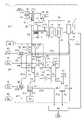
- FIG. 1is a block diagram showing an embodiment according to the present invention.
- FIG.It is a block diagram which shows the 1st modification which concerns on this invention. It is a block diagram which shows the 2nd modification which concerns on this invention. It is a block diagram which shows the 2nd modification which concerns on this invention.
- FIG.Where it is not necessary for the present invention to distinguish between ionic and molecular forms, the notation “ammonia” includes both ammonia molecules and ammonium ions. Therefore, “ammonia-containing waste water” also includes waste water containing ammonia in the form of ammonium ions.
- numeralsonly represent physical elements such as devices, parts, and parts related to the system in the embodiments and modifications of the present invention. Also, a symbol combining an alphabetic character F and a number represents a fluid such as liquid or gas generated in this system, and a symbol combining an alphabetic character P and a number represents a position.
- FIG. 1is a block diagram showing a hydrogen and ammonia production system 1 according to an embodiment.
- the hydrogen and ammonia production system 1includes a boiler 16 that generates steam from the heat of a combustion chamber (or a combustion furnace) 11, and an exhaust gas treatment device 19 that treats exhaust gas from the combustion chamber 11 and discharges exhaust gas treated wastewater F1.
- a first ammonia recovery device 21that recovers ammonia contained by diffusion treatment of exhaust gas treatment wastewater F1 of the plant 10 to produce a first concentrated ammonia water F4, and a boiler blow water F3 of the plant 10.
- a second ammonia recovery device 24that performs a diffusion treatment together with the first concentrated ammonia liquid 21 to produce a second concentrated ammonia water F8, and an ion removing device 27 that removes remaining alkaline components from the waste water F9 of the second ammonia recovery device 24.
- a water electrolysis device 28that produces hydrogen F12 by water electrolysis of permeated water F11 from which alkali components have been removed, and ions that are alkali components removed by the ion removal device 27
- a comprehensive wastewater treatment apparatus 40having organic and inorganic wastewater treatment apparatuses that uses the concentrated liquid F10 as an alkali source and treats plant wastewater F16 discharged from the plant 10 until it can be discharged.
- any plant having a combustion chamber and a boiler that generates steam from the heat of the combustion chamber, that is, a combustion plantcan be applied. Can be applied to plants.
- the hydrogen and ammonia production system 1may be constructed by continuing the transportation route such as pipelines and automobiles as appropriate.
- the valuables generation facility 20 and the comprehensive wastewater treatment device 40may be arranged and configured on the same site as the plant 10 as ancillary equipment of the plant 10, or may be arranged on separate sites from each other.
- the hydrogen and ammonia production system 1may be configured by continuing the transportation route such as a car or a car.
- the combustion chamber 11(or combustion furnace) is the equipment that burns the fuel.
- the fuelis generally waste (municipal waste or industrial waste), and if it is a thermal power plant or a chemical plant, the fuel is generally coal, petroleum, Green fuel such as natural gas, woody biomass, and biogas produced by fermentation or the like.
- ammonia or hydrogenfor example, ammonia or hydrogen produced by the ammonia production system 1 may be used.
- the combustion chamber 11may be provided as a facility associated with the boiler 16 (for example, built into the boiler 16), which will be described later.
- Exhaust gas generated in the combustion chamber 11flows sequentially through the flue as follows and is discharged from the chimney 15 into the atmosphere. That is, the exhaust gas is divided into a dust collector 13 for removing dust from the exhaust gas and a wet treatment device 14 for removing harmful components such as sulfur oxides (SOx) from the exhaust gas dust-removed by the dust collector 13 using a method such as a lime-gypsum method. and a chimney 15 for releasing the exhaust gas from which harmful components have been removed to the atmosphere.
- a dust collector 13for removing dust from the exhaust gas
- SOxsulfur oxides
- a wet treatment device 14for removing harmful components such as sulfur oxides (SOx) from the exhaust gas dust-removed by the dust collector 13 using a method such as a lime-gypsum method.
- a chimney 15for releasing the exhaust gas from which harmful components have been removed to the atmosphere.
- Exhaust gas treated waste water F1which is ammonia-containing waste water, is discharged from the wet treatment device 14 .
- the exhaust gas treated waste water F1contains scale components such as Ca 2+ and Mg 2+ .
- the ammonia concentration of the exhaust gas treated water F1is about 50 to 50,000 mg/L, preferably about 1,000 to 20,000 mg/L, more preferably about 2,000 to 10,000 mg/L.
- the discharged exhaust gas treated waste water F1is introduced into the first ammonia recovery device 21 of the valuable resource generation facility 20, which will be described later.
- the exhaust gas treated waste water F1may be stored in a waste water storage tank (not shown) and then introduced into the first ammonia recovery device 21 .
- the boiler 16is a device that recovers heat from the combustion chamber 11 to generate steam F2.
- the boiler 16includes a pure water production device 50 that produces pure water from tap water, industrial water, etc., an additive supply device 51 that adds additives such as pH adjusters to the produced pure water, A steam drum 52 that stores pure water (boiler water), a heat recovery device 53 such as a heat transfer tube or a superheating tube that turns the boiler water stored in the steam drum 52 into steam F2 with the heat of exhaust gas, and
- a steam turbine 54that rotates an impeller with the steam stored in the steam drum 52, a generator 55 that generates electricity with the rotational force of the impeller of the steam turbine 54, and steam (waste water) after rotating the impeller of the steam turbine 54 a condenser 56 for returning steam) to water;
- Types of chemicals added hereinclude, for example, boilers, corrosion inhibitors (oxidizers), scale inhibitors, etc., and include at least ammonia for corrosion prevention.
- the boiler 16has a mechanism for discharging (blowing) part of the boiler water to the outside through a blow pipe in order to prevent various components contained in the boiler water from being concentrated.
- the boiler water discharged to the outside of the boiler 16is called boiler blow water F3.
- the boiler blow water F3is waste water containing ammonia supplied as an additive (ammonia-containing waste water), and is introduced into the second ammonia recovery device 22 of the valuables production facility 20, which will be described later.
- the water stored in the steam drum 21has a pH value of about 9 to 10 (for example, a pH value of about 10.3). degree.
- the boiler blow water F3may be stored in a waste water storage tank (not shown) and then introduced into the second ammonia recovery device 22 .
- the electric power generated by the generator 55is used as electric power in the hydrogen and ammonia production system 1, and surplus electric power can be sold to electric power companies.
- the steam F2can also be used for heat utilization equipment inside and outside the hydrogen and ammonia production system 1 .
- the valuables production facility 20uses wastewater (ammonia-containing wastewater) discharged from the plant 10 to produce valuables. Specific examples of valuables produced at the valuables production facility 20 include hydrogen and ammonia, and urea and methane are also produced.
- the first ammonia recovery device 21is a device that recovers ammonia contained in the exhaust gas treated waste water F1 by stripping to produce the first ammonia concentrate F4.
- the first pH adjuster supply device 23is a device that supplies an alkaline chemical (for example, sodium hydroxide or the like) for adjusting the pH inside the first ammonia recovery device 21 .
- a stripping towerstripping tower partitioned into multiple stages with packing materials, trays, and separation cylinders is arranged as one long stripping tower in the vertical direction, or continuously in series. It is provided as a plurality of connected radiating towers.
- one stripping toweris used as an example, and the stripping tower is partitioned into three stages in the vertical direction by two trays as an example.
- One diffusion towermay be partitioned into four or more stages with three or more trays.
- high-temperature (approximately 70° C. to approximately 90° C.) exhaust gas treated waste water F1is injected from the top of the diffusion tower.
- the exhaust gas treated waste water F1gradually descends downward inside the diffusion tower while diffusing in the form of mist.
- high-temperature steamis supplied from the lower part of the diffusion tower so as to face the descending exhaust gas treated waste water F1. This vapor moves upward while diffusing in the form of mist inside the diffusion tower. Due to such gas-liquid contact between the exhaust gas treated waste water F1 and the steam, ammonia in the exhaust gas treated waste water F1 is transferred to the gas phase and recovered.
- the pH of the exhaust gas treated waste water in the first ammonia recovery deviceis more than 8 and less than 9.5. Below pH 8, diffusion of ammonia is difficult.
- the dissolved amount of Ca 2+ and Mg 2+which are scale components in the exhaust gas treated waste water F1 depends on the pH, and if the pH exceeds 9.5, the scale components are likely to precipitate. Since the flue gas treated waste water F1 contains a large amount of scale components, the first ammonia recovery device 21 does not dare to raise the pH, and performs stripping within a pH range in which scale is less likely to deposit.
- the exhaust gas treatment wastewater F1has a relatively high ammonia concentration, and as described later, it is necessary to excessively raise the pH in stripping for recovering the necessary amount of ammonia as an ammonia source to be mixed with the boiler blow water F3. No.
- the exhaust gas treated waste water F1is at a high temperature (approximately 70° C. to approximately 90° C.) and ammonia is easily liberated, it is not necessary to raise the pH to a range where scale is likely to be generated. Therefore, the amount of alkali chemicals supplied from the first pH adjuster supply device 23 can be reduced, and the cost of chemicals can be reduced.
- the ammonia and water vapor that have transitioned to the gas phaseare discharged from the upper part of the diffusion tower and recovered as the first concentrated ammonia liquid F4, after which they are introduced into the second ammonia recovery device 22 together with the boiler blow water F3.
- the ammonia concentration of the first ammonia concentrate F4is, for example, about several percent to 10%.
- the steam F2 generated by the boiler 16may be used as the steam supplied from the lower part of the stripping tower, or other steam may be used. Also, among the steam F2, if the waste steam after being supplied to the steam turbine 54 is reused, the cost of using the steam can be reduced.
- the second ammonia recovery device 22is a device that recovers the ammonia contained in the boiler blow water F3 by stripping to produce the second ammonia concentrate F8.
- the second pH adjuster supply device 24is a device that supplies an alkaline chemical (for example, sodium hydroxide or the like) for adjusting the pH inside the second ammonia recovery device 22 .
- the second ammonia recovery device 22is also provided with a stripping tower similar to the first ammonia recovery device 21 .
- the first ammonia concentrate F4is injected from the upper part of the stripping tower together with the boiler blow water F3 of high temperature (approximately 70° C. to approximately 90° C.).
- a liquid mixture obtained by mixing the first concentrated ammonia liquid F4 and the boiler blow water F3 in advanceis injected.
- the mixed liquid of the boiler blow water F3 and the first concentrated ammonia liquid F4gradually descends downward inside the stripping tower while diffusing in the form of mist.
- high-temperature steamis supplied from the lower part of the stripping tower so as to face the descending liquid mixture. This vapor moves upward while diffusing in the form of mist inside the diffusion tower.
- ammonia in the mixed liquidDue to such gas-liquid contact between the mixed liquid and the steam, ammonia in the mixed liquid is transferred to the gas phase and recovered.
- the ammonia concentration in the boiler blow water F3is increased by introducing the first ammonia concentrate F4 containing high concentration ammonia into the second ammonia recovery device 22 together with the boiler blow water F3 containing relatively low concentration ammonia. can be done.
- the pH of the mixed solutioncan be adjusted to, for example, 10 to 12 by supplying an alkaline agent from the second pH adjuster supply device 24 .
- both the boiler blow water F3 and the first concentrated ammonia solutionhave high pH values, and the amount of alkaline agent supplied from the second pH adjuster supply device 24 is small. Furthermore, since the boiler blow water F3 is at a high temperature (approximately 70° C. to approximately 90° C.) and the first ammonia concentrate F4 is also at a high temperature, the cost of heating each liquid can be reduced. Thus, in the second ammonia recovery device 22, stripping can increase the efficiency of recovering ammonia. Alternatively, the first ammonia concentrate F4 and the boiler blow water F3 may be individually injected into the second ammonia recovery device 22 and mixed inside the second ammonia recovery device 22 without being mixed in advance.
- the ammonia and water vapor that have transitioned to the gas phaseare discharged from the upper part of the diffusion tower and recovered as the second concentrated ammonia liquid F8.
- the ammonia concentration of the second concentrated ammonia solution F8is higher than that of the first concentrated ammonia solution F4, for example about 25% to about 50%.
- the second ammonia concentrate F8can be supplied, for example, as a fuel or raw material to ammonia utilization equipment 41 such as chemical plants and ammonia gas turbines.
- the second ammonia concentrate F8may be supplied from the ammonia supply device 12 into the exhaust gas and used as a denitration agent (reducing agent for reducing NOx to nitrogen), or may be used for manufacturing chemical products. .
- the steam F2 generated by the boiler 16may be used as the steam supplied from the lower part of the stripping tower, or other steam may be used. Also, among the steam F2, if the waste steam after being supplied to the steam turbine 54 is reused, the cost of using the steam can be reduced.
- Waste water F5 from which ammonia has been removedstays in the lower part of the diffusion tower of the first ammonia recovery device 21 .
- This waste water F5is introduced into the flocculation treatment tank 26 .
- the coagulation treatment tank 26is a tank for removing scale components F7 (eg, Ca 2+ , Mg 2+ , etc.) contained in the waste water F5.
- the coagulant treatment tank 26is provided with a coagulant supply device 25 that supplies a coagulant for coagulating the scale components F7 in the waste water F5.
- the flocculant supplied by the flocculant supply device 25may be an inorganic flocculant (e.g., ferric chloride solution, etc.) or an organic flocculant (e.g., polymer flocculant, etc.). good too.
- the scale component F7 in the waste water F5is precipitated as a solid inside the coagulation treatment tank 26, and can be easily removed. Condensed waste water F6 (supernatant) from which the scale component F7 has been removed from the waste water F5 is supplied to the integrated waste water treatment device 40 .
- the waste water F5may be supplied directly to the general waste water treatment facility 40 without installing the coagulation treatment tank 26.
- the ion removal device 27is a device for removing alkali components (unnecessary ions) such as ammonia and sodium hydroxide in the waste water F9 remaining after the stripping treatment.
- the ion removing device 27is provided with, for example, an ion exchange tower filled with an RO membrane (reverse osmosis membrane) or an ion exchange resin (for example, a high temperature ion exchange resin).
- the RO membraneis a membrane that allows hydrogen ions (H + ) and hydroxide ions (OH ⁇ ) in water to pass through and blocks the passage of other ions (eg, Ca 2+ , Mg 2+ , NH 4 + etc.).
- the ion exchange resinis a gel-like synthetic resin bead that replaces unnecessary ions in water with hydrogen ions or hydroxide ions.
- a heat-resistant cation exchange resinis used.
- the ion concentrate F10 containing ammonia components and other residual alkali componentsis supplied to the integrated wastewater treatment apparatus 40 and reused as an alkali source (ammonia source) in organic or inorganic wastewater treatment.
- the residual alkaline component contained in the ion concentrate F10can be used as an ammonia source for wastewater treatment.
- the waste water F9 from the second ammonia recovery device 22can be effectively reused as a resource.
- the waste water F9is the waste water after the ammonia is recovered by the second ammonia recovery device, and the amount of chemicals for recovering the ammonia is small.
- the water electrolysis device 28is a device that electrolyzes the permeated water F11 generated by the ion removing device 27 to produce hydrogen F12.
- a water electrolysis apparatusis supplied with water containing no or very few impurities, pure water, or water substantially equivalent to pure water for electrolysis. Therefore, the permeated water F11 is pure water or water substantially equivalent to pure water.
- the hydrogen F12 generated hereis supplied as a fuel or raw material to a hydrogen utilization facility 42 such as a chemical plant, a fuel cell, or a hydrogen gas turbine, for example. Oxygen that may be generated during electrolysis of the permeated water F11 may be released to the atmosphere, supplied to the inside of the combustion chamber 11 as a combustion accelerator, or stored in an oxygen storage tank (not shown).
- a water electrolyzeris equipped with a heating device for heating room-temperature pure water, etc., in order to perform electrolysis efficiently. growing.
- the water electrolysis device 28 according to the embodimentcan reduce the energy required for the heating device. This is because the boiler blow water F3, which is the raw material of the water electrolysis device 28, is at a high temperature, and the water temperature of the permeated water F9 separated by the ion removal device 27 is also high, so it is easy to adjust the temperature to a temperature higher than normal temperature.
- the comprehensive wastewater treatment equipment 40is a wastewater treatment facility having various equipment for treating plant wastewater F16 including various wastewater discharged from the plant, for example, an organic treatment equipment and an inorganic treatment equipment.
- the organic system treatment apparatusis a wastewater treatment apparatus in which biological treatment (wastewater treatment by the action of microorganisms) is performed and which is provided with a nitrification tank, a denitrification tank, an aeration tank, and the like.
- An inorganic treatment apparatusis a wastewater treatment apparatus in which inorganic water treatment is performed.
- the organic treatment apparatusis provided with, for example, a nitrification tank, a denitrification tank, an aeration tank, etc., and ammonia in the wastewater is removed as nitrogen by the action of nitrification bacteria, denitrification bacteria, and the like.
- the inorganic treatment apparatusis provided with, for example, a chemical reaction tank, a sedimentation tank, a filtration tank, etc., and chemically removes impurities, metals, and the like in waste water.
- the wastewater treated by the comprehensive wastewater treatment apparatus 40may be reused in the plant 10, the valuables generating facility 20 and the comprehensive wastewater level treatment apparatus 40, or may be discharged to the outside.
- the ammonia concentration suitable for stripping treatmentis about 2000 mg/L.
- boiler blow water F3has a relatively low ammonia concentration and is often unsuitable for stripping.
- the boiler blow water F3has a water temperature of about 80°C, a discharge amount of about 150 m 3 /day, and an ammonia concentration of about 600 mg/L
- the exhaust gas treated waste water F1has a water temperature of about 80°C and a discharge amount of about 80 m 3 /day.
- that the ammonia concentrationis 3000 mg/L.
- the amount of boiler blow water F3 dischargedis large and the concentration of ammonia contained therein is low. Therefore, it is difficult to efficiently recover ammonia if only the boiler blow water F3 is used for the stripping treatment.
- the exhaust gas treated waste water F1is stripped by the first ammonia recovery device 21 to recover ammonia.
- the free ammoniabecomes about 90% at a high temperature of about 80 ° C., and when all the free ammonia is recovered, the ammonia concentration is about 54000 mg / L.
- About 4 m 3 of first ammonia concentrate F4can be recovered.
- the recovered first ammonia concentrate F4is introduced into the second ammonia recovery device 22 together with the boiler blow water F3, and stripped again.
- the ammonia concentration of the mixed liquid of the boiler blow water F3 and the first ammonia concentrate F4is about 2000 mg/L, and the ammonia concentration suitable for the stripping process is obtained. Therefore, the stripping efficiency of ammonia in the second ammonia recovery device 22 is improved. Further, if the pH of the mixed solution is adjusted and the stripping treatment is performed by the second ammonia recovery device 22, for example, a 25% concentration ammonia solution distributed in the market can be easily obtained as the second concentrated ammonia solution F8.
- the concentration of ammonia remaining in the waste water F9 discharged from the second ammonia recovery device 22is approximately 200 mg/L. If this waste water F9 is supplied to the ion remover 27 and concentrated using a high-temperature ion exchange resin, an ion-concentrated liquid F10 in which residual alkaline components are concentrated and a permeated water F11 are obtained.
- the volume of the ion concentrate F10 obtained hereis about 6 m 3 and the concentration of the residual alkaline component is about 5000 mg/L.
- the concentration of residual alkaline componentsis converted to ammonia nitrogen, it can be used as an alkaline source (ammonia source) in the treatment of organic wastewater up to about 200 m 3 per day, and is suitable for retaining bacteria in organic biological treatment. is.
- the first concentrated ammonia solution F4is produced from the exhaust gas treatment wastewater F1 by the first ammonia recovery device 21, and this first concentrated ammonia solution F4 is produced together with the boiler blow water F3 by the second ammonia recovery device. 22 to produce the second ammonia concentrate F8, the efficiency is higher than that of stripping the exhaust gas treatment wastewater F1 and the boiler blow water F3 individually or by mixing the exhaust gas treatment wastewater F1 and the boiler blow water F3. Ammonia can be recovered well.
- a large amount of chemicalsare used to capture ammonia contained in the boiler blow water F3 by pretreatment, or a large amount of chemicals is used to remove exhaust gas treated wastewater F1.
- Ammoniacan be easily recovered without the need to adjust the pH of the solution to remove scale components and adjust the pH again. Therefore, according to the hydrogen and ammonia production system 1 described above, the wastewater from the plant 10 can be reused for the production of valuables (eg, hydrogen and ammonia) and chemical products, and valuables can be efficiently and inexpensively produced from the wastewater from the plant 10. can.
- valuableseg, hydrogen and ammonia
- FIG. 2is a block diagram showing the configuration of a hydrogen and ammonia production system 1' according to the first modification.
- the same reference numeralsare assigned to the same configurations as those described in the embodiments, and descriptions of the configurations and effects are omitted as appropriate.
- the hydrogen and ammonia production system 1'includes a second flow path that supplies part of the first ammonia concentrate F4 to the first ammonia recovery device 22 at a position different from the boiler blow water F3, and the boiler blow water F3 and the first flow path has a valuable resource generation facility 20' for flowing the first concentrated ammonia F4 to the second flow path when the ratio of the amount of ammonia in the first concentrated ammonia F4 is a predetermined value or more.
- a first flow path 60for mixing the first concentrated ammonia solution F4 with the boiler blow water F3;
- a second flow path 61supplied to the second flow path 61, a control valve 62 that adjusts the flow rate of the first concentrated ammonia F4 that flows through the second flow path 61, a control device 63 that controls the control valve 62, and the ammonia concentration of the boiler blow water F3
- Ammonia concentration meter 64for measuring, flow meter 65 for measuring flow rate of boiler blow water F3, ammonia concentration meter 66 for measuring ammonia concentration of first ammonia concentrate F4 in first flow path 60, first flow path a flow meter 67 for measuring the flow rate of the first ammonia concentrate F4 at 60;
- the control device 63calculates the ratio of the ammonia amount of the first concentrated ammonia liquid F4 to the boiler blow water F3 from the ammonia concentration and flow rate values measured by the ammonia concentration meter and the flow meter of each liquid, and the ratio of the ammonia amount
- a predetermined amount of about 1/10 of the first flow path, for example, the first concentrated ammonia solution F4is supplied.
- a pH metermay be installed to obtain the ammonia concentration from the measured pH value.
- the position in the vertical direction of the second ammonia recovery device 22 where the mixed liquid of the boiler blow water F3 mixed with the first concentrated ammonia liquid F4 is suppliedis a third position P3, and the first concentrated ammonia flowing through the second flow path 61
- the fourth position P4is preferably set at a position different from the third position P3, more preferably the fourth position P4.
- a fourth position P4is set above the third position P3.
- the fourth position P4is arranged in a section above the third position P3.
- the first ammonia concentrate F4 in the first flow pathmay be supplied to a position where it is mixed with the boiler blow water F3 in the second ammonia recovery device 22 without being mixed with the boiler blow water F3 in advance.
- the first concentrated ammonia liquidmay be supplied from the vicinity of the position P3 and mixed with the boiler blow water F3.
- the mist-like liquid to be treated supplied from each placecan be easily diffused evenly inside the stripping tower, and the ammonia vaporization efficiency can be improved.
- the fourth position P4 above the third position P3the time and distance required for ammonia to vaporize from the first concentrated ammonia liquid F4 supplied to the second ammonia recovery device 22 are ensured. and the efficiency of ammonia vaporization can be further improved. Therefore, the concentration of ammonia in the second ammonia recovery device 22 can be promoted.
- FIG. 3is a block diagram showing the configuration of the hydrogen and ammonia production system 1′′ according to the second modification.
- the same configurations as those described in the embodimentare denoted by the same reference numerals, and the configurations and effects are described. The description is omitted as appropriate.
- the hydrogen and ammonia production system 1′′uses a portion of the first concentrated ammonia liquid F4 and a portion of the second concentrated ammonia liquid F8 as the first ammonia recovery device 21 and the second ammonia recovery device 22 Each of them has a valuable resource generation facility 20′′ to be circulated.
- part of the first concentrated ammonia F4is re-introduced to the first ammonia recovery device 21 via the first circulation path 31.
- part of the second concentrated ammonia F8 Partis reintroduced into the second ammonia recovery device 22 via the second circulation path 32.
- a more concentrated second ammonia concentrate F8can be obtained according to the change in the flow rate of the boiler blow water F3.
- the vertical position at which the exhaust gas treated waste water F1 is supplied to the first ammonia recovery device 21is defined as a first position P1, and the vertical position at which the first concentrated ammonia solution F4 is reintroduced from the first circulation path 31. is the second position P2.
- the second position P2may be set at the same position as the first position P1, but is preferably set at a position different from the first position P1. Also, more preferably, the second position P2 is set above the first position P1.
- the second position P2is arranged in the uppermost section in the ammonia recovery device 21 whose inside is divided into three sections, and the first position P1 is arranged in a section lower than the second position P2. It should be noted that the same effect can be obtained even if they are installed at the same positions as long as the positions are different from each other in the vertical direction.
- the mist-like liquid to be treated supplied from each placecan be easily and evenly diffused inside the stripping tower, and the ammonia vaporization efficiency can be improved.
- the second position P2 above the first position P1the time and distance required for ammonia to vaporize from the first concentrated ammonia liquid F4 that has been reintroduced into the first ammonia recovery device 21 is ensured. and can further improve the vaporization efficiency of ammonia. Therefore, the concentration of ammonia in the first ammonia recovery device 21 can be promoted.
- the position in the vertical direction where the second concentrated ammonia solution F8 is reintroduced from the second circulation path 32is defined as a fifth position P5.
- the fifth position P5may be set at the same position as the third position P3 or the fourth position P4, but is preferably set at a position different from the third position P3 or the fourth position P4. More preferably, the fifth position P5 is set above the third position P3 and the fourth position P4.
- the mist-like liquid to be treated supplied from each placetends to diffuse evenly inside the stripping tower, and the ammonia vaporizes. can improve efficiency.
- the fifth position P5higher than the third position P3 and the fourth position P4, the second ammonia recovery device 22 requires a Time and distance can be easily secured, and the ammonia vaporization efficiency can be further improved. Therefore, the concentration of ammonia in the second ammonia recovery device 22 can be promoted.
- the waste water from the plant 10can be reused for the production of valuable substances (eg, hydrogen and ammonia) and chemical products, and the waste water from the plant 10 can be used to efficiently and inexpensively produce valuable substances. can.
- valuable substanceseg, hydrogen and ammonia
- FIG. 4is a block diagram showing the configuration of a hydrogen and ammonia production system 1''' according to the third modification.
- the hydrogen and ammonia production system 1''' according to the second modificationis applied to a plant 10''' having a carbon dioxide separation device 18, and a urea production device 33 and It has a valuables generation facility 20''' with a methanation device 34.
- the carbon dioxide separation device 18is a device for recovering carbon dioxide F13 contained in the exhaust gas.
- a method for recovering carbon dioxide F13various known methods can be employed.
- carbon dioxide F13may be recovered from exhaust gas using a polymer separation membrane (carbon dioxide separation membrane).
- a medium having high absorption performance and adsorption performance for carbon dioxide F13may be brought into contact with the exhaust gas to recover.
- activated carbon or zeoliteis allowed to adsorb carbon dioxide F13 in the exhaust gas, and the carbon dioxide F13 may be recovered by heating or depressurization.
- a liquid mediumis used, the carbon dioxide F13 may be absorbed and recovered by an amine solution, an aqueous potassium carbonate solution, an ammonia solution, or the like.
- the recovered carbon dioxide F13 and the hydrogen F12 and ammonia concentrate F8 produced by the hydrogen and ammonia production systemcan be supplied to the urea manufacturing device 33, and the recovered carbon dioxide F13 and hydrogen F12 can be supplied to the methanation device .
- the urea production device 33is a device that synthesizes the carbon dioxide F13 and the second ammonia concentrate F8 to produce urea F14 (CH 4 N 2 O).
- the urea production apparatus 33is provided with a reactor (non-catalyst vessel) for maintaining a high temperature and high pressure state, in which urea F14 is produced.
- the urea F14 produced hereis supplied to the urea utilization facility 43 .
- the urea utilization facility 43includes, for example, a chemical plant, a plant factory using urea F14 as a fertilizer, and the like.
- the methanation device 34is a device that synthesizes carbon dioxide F13 and hydrogen F12 to produce methane F15 (CH 4 ).
- methane F15is synthesized by a methanation reaction or a Sabatier reaction via a co-electrolytic reaction.
- the methanation device 34is provided with a reactor (catalyst container) containing a catalyst for methane synthesis, and methane F15 is generated therein.
- the methane F15 generated hereis supplied to the methane gas utilization equipment 44 .
- the methane gas utilization facility 44includes, for example, buildings and facilities (gas pipes) that use methane F15 as fuel (city gas), gas engines that burn methane F15 to generate power, and the like.
- the carbon dioxide separator 18 in the plant 10'''by providing the carbon dioxide separator 18 in the plant 10''', the carbon dioxide F13 in the exhaust gas can be removed, and the amount of carbon dioxide F13 discharged from the stack 15 can be greatly reduced.
- the urea production device 33 in the valuable resource generation facility 20'''the urea F14 can be easily produced using the carbon dioxide F13 and the second ammonia concentrate F8 produced in the valuable resource generation facility 20'''.
- methanation device 34 in the valuable resource generation facility 20′′methane F15 can be easily generated using the carbon dioxide F13 and the hydrogen F12 produced at the valuable resource generation facility. can be done.
- the wastewater from the plant 10'''can be reused for the production of valuables (such as hydrogen, ammonia, urea, and methane) and chemical products.
- valuablessuch as hydrogen, ammonia, urea, and methane
- Valuablescan be produced efficiently and inexpensively from
Landscapes
- Chemical & Material Sciences (AREA)
- Engineering & Computer Science (AREA)
- Environmental & Geological Engineering (AREA)
- Organic Chemistry (AREA)
- Chemical Kinetics & Catalysis (AREA)
- Analytical Chemistry (AREA)
- Oil, Petroleum & Natural Gas (AREA)
- General Chemical & Material Sciences (AREA)
- Life Sciences & Earth Sciences (AREA)
- Health & Medical Sciences (AREA)
- Biomedical Technology (AREA)
- Water Supply & Treatment (AREA)
- Hydrology & Water Resources (AREA)
- Inorganic Chemistry (AREA)
- Microbiology (AREA)
- Electrochemistry (AREA)
- Materials Engineering (AREA)
- Metallurgy (AREA)
- Biodiversity & Conservation Biology (AREA)
- Dispersion Chemistry (AREA)
- Sustainable Development (AREA)
- Nanotechnology (AREA)
- Combustion & Propulsion (AREA)
- Physical Water Treatments (AREA)
- Electrolytic Production Of Non-Metals, Compounds, Apparatuses Therefor (AREA)
- Treating Waste Gases (AREA)
- Separation Using Semi-Permeable Membranes (AREA)
- Gas Separation By Absorption (AREA)
- Treatment Of Water By Ion Exchange (AREA)
- Purification Treatments By Anaerobic Or Anaerobic And Aerobic Bacteria Or Animals (AREA)
- Organic Low-Molecular-Weight Compounds And Preparation Thereof (AREA)
Abstract
Description
Translated fromJapanese本発明は、燃焼室およびボイラを備えた燃焼プラントの排水を利用して水素及びアンモニアを製造するシステムに関する。The present invention relates to a system for producing hydrogen and ammonia using wastewater from a combustion plant equipped with a combustion chamber and a boiler.
従来、燃焼プラントの排水に含まれるアンモニアを除去するために、イオン交換による手法やストリッピングによる手法が知られている。
特許文献1には、ボイラブロー排水をカチオン交換体に通液してアンモニアをカチオン交換体に捕捉させ、カチオン交換体に対して再生処理を行うことでアンモニア濃縮排水を取得する手法が記載されている。カチオン交換体の再生処理においては、塩酸、硫酸、水酸化ナトリウム等の薬品が添加される。また、アンモニア濃縮排水をアンモニア回収装置へ導入し、ストリッピングによりアンモニアを気相に移行させてアンモニアガスとして回収することも記載されている。Conventionally, methods using ion exchange and methods using stripping are known for removing ammonia contained in wastewater from combustion plants.
特許文献2には、硬度成分を含むアンモニア含有排水(排煙脱硫装置の排水)のストリッピングに際し、アンモニア含有排水をストリッピング装置(アンモニア放散塔)へ導入する前に硬度成分を除去する手法が記載されている。まず、アンモニア含有排水にアルカリが添加され、pH(水素イオン指数)が8~14に調整される。続いて、凝集助剤が添加され、沈殿物として析出された硬度成分が除去される。沈殿物を含まない上澄排水は、酸の添加によりpHが調整されてストリッピング装置へと供給され、ストリッピングによりアンモニアガスが回収される。Patent Document 2 discloses a method of removing hardness components before introducing the ammonia-containing waste water into a stripping device (ammonia stripping tower) when stripping ammonia-containing waste water (effluent of flue gas desulfurization equipment) containing hardness components. Are listed. First, an alkali is added to ammonia-containing waste water to adjust the pH (hydrogen ion index) to 8-14. Subsequently, a flocculation aid is added, and hardness components precipitated as precipitates are removed. The precipitate-free supernatant effluent is pH-adjusted by the addition of acid and supplied to a stripping device, where ammonia gas is recovered by stripping.
特許文献1の技術では、カチオン交換体の再生処理、すなわち、カチオン交換体に捕捉されたアンモニアを取り出すための薬品が大量に必要となり、アンモニア濃縮排水を得るためのコストが高い。特許文献2の技術においても、pHを調整するための薬品が大量に必要となり、薬品コストの問題を解決できない。
また両者を混合してから処理しようとすると排ガス処理水のスケール成分が増えてボイラブロー水のアンモニア濃度が薄くなるので、前処理に係る薬剤を多量に添加する必要が生じる。従って、既存の技術では、プラントの排水に含まれる有価物を効率的に回収することができなかった。The technique of
Also, if the two are mixed before being treated, the amount of scale components in the exhaust gas treated water will increase and the ammonia concentration in the boiler blow water will decrease, so it will be necessary to add a large amount of chemical for pretreatment. Therefore, the existing technology could not efficiently recover the valuables contained in the waste water of the plant.
本発明は、上記のような課題に鑑み案出されたものであり、プラントの排水から有価物を効率よく安価に生成できるようにした水素及びアンモニア製造システムを提供することを目的とする。The present invention has been devised in view of the above problems, and aims to provide a hydrogen and ammonia production system that can efficiently and inexpensively produce valuable substances from plant wastewater.
本発明の水素及びアンモニア製造システムは、
燃焼炉又は燃焼室の熱で蒸気を生成し、ボイラブロー水を排出するボイラと、
前記燃焼炉又は前記燃焼室から発生する排ガスを処理し、排ガス処理排水を排出する排ガス処理装置と、を備えるプラントにおいて、
前記排ガス処理排水をストリッピング処理してアンモニアを回収し第1アンモニア濃縮液を製造する第1アンモニア回収装置と、
前記第1アンモニア濃縮液を前記ボイラブロー水とともにストリッピング処理してアンモニアを回収し第2アンモニア濃縮液を製造する第2アンモニア回収装置と、
前記第2アンモニア回収装置から排出された前記ボイラブロー水を通液させて、透過水を得ると共に、残存アルカリ成分を含むイオン濃縮液とに分離するイオン除去装置と、
前記透過水を電解して水素を製造する水電解装置と、
前記イオン濃縮液をアルカリ源として投入する前記プラントの有機若しくは無機排水処理装置を備える。The hydrogen and ammonia production system of the present invention is
a boiler that generates steam with the heat of the combustion furnace or combustion chamber and discharges boiler blow water;
A plant comprising an exhaust gas treatment device that treats exhaust gas generated from the combustion furnace or the combustion chamber and discharges exhaust gas treatment wastewater,
a first ammonia recovery device for stripping the exhaust gas treated wastewater to recover ammonia to produce a first ammonia concentrate;
a second ammonia recovery device for stripping the first concentrated ammonia solution together with the boiler blow water to recover ammonia to produce a second concentrated ammonia solution;
an ion removal device that passes the boiler blow water discharged from the second ammonia recovery device to obtain permeated water and separates it into an ion concentrate containing a residual alkaline component;
a water electrolysis device that electrolyzes the permeated water to produce hydrogen;
An organic or inorganic wastewater treatment device for the plant into which the ion concentrate is introduced as an alkalinity source.
本発明の水素及びアンモニア製造システムによれば、アンモニア含有排水である排ガス処理排水をストリッピング処理して第1アンモニア濃縮液を回収し、当該第1アンモニア濃縮液をアンモニア含有排水であるボイラブロー水とともにストリッピング処理することで、ボイラブロー水から第2アンモニア濃縮液を回収できる。これらの排水を個々に処理してアンモニアを回収したりこれらの排水を混合して処理したりするよりも、必要な薬品量を低減させてコストを削減できる。また第2アンモニア濃縮液が回収された残りのボイラブロー水からイオン除去装置を利用して得られた透過水は、水電解して水素を製造できる。従って、本発明の水素及びアンモニア製造システムは、プラントのアンモニア含有排水から有価物を効率よく安価に生成できる。According to the hydrogen and ammonia production system of the present invention, the exhaust gas treatment wastewater, which is ammonia-containing wastewater, is stripped to recover the first ammonia concentrate, and the first ammonia concentrate is recovered together with the boiler blow water, which is ammonia-containing wastewater. The second concentrated ammonia solution can be recovered from the boiler blow water by stripping. Compared to treating these wastewaters individually to recover ammonia or mixing and treating these wastewaters, the required amount of chemicals can be reduced and costs can be reduced. Hydrogen can be produced by water electrolysis of permeated water obtained by using an ion removal device from the remaining boiler blow water from which the second concentrated ammonia solution has been recovered. Therefore, the hydrogen and ammonia production system of the present invention can efficiently and inexpensively produce valuable substances from ammonia-containing waste water of a plant.
以下、図1~図4を参照して、本発明の水素及びアンモニア製造システムについて説明する。本発明においてイオン形であるか分子形であるかを区別する必要がない場合では、「アンモニア」との表記はアンモニア分子とアンモニウムイオンの両方を含む。従って「アンモニア含有排水」にはアンモニウムイオンの形態でアンモニアを含む排水も含まれる。
図中において、数字のみの符号は、本発明の実施例及び変形例において本システムに関係する装置、部品、部位等の物理的な要素を表す。また、アルファベットのFと数字とを組み合わせた符号は、本システムで生じる液体や気体などの流体(Fluid)を表し、アルファベットのPと数字とを組み合わせた符号は位置(Position)を表す。なお、以下に示す実施例及び変形例は、あくまでも例示に過ぎず、明示しない種々の変形や技術の適用を排除する意図はない。以下の各構成は、それらの趣旨を逸脱しない範囲で種々変形して実施できる。また、以下の各構成は、本発明に必須の構成を除いて必要に応じて取捨選択でき、あるいは公知の構成と組み合わせ可能である。Hereinafter, the hydrogen and ammonia production system of the present invention will be described with reference to FIGS. 1 to 4. FIG. Where it is not necessary for the present invention to distinguish between ionic and molecular forms, the notation "ammonia" includes both ammonia molecules and ammonium ions. Therefore, "ammonia-containing waste water" also includes waste water containing ammonia in the form of ammonium ions.
In the drawings, numerals only represent physical elements such as devices, parts, and parts related to the system in the embodiments and modifications of the present invention. Also, a symbol combining an alphabetic character F and a number represents a fluid such as liquid or gas generated in this system, and a symbol combining an alphabetic character P and a number represents a position. It should be noted that the examples and modifications shown below are merely examples, and are not intended to exclude various modifications and application of techniques that are not explicitly stated. Each configuration described below can be modified in various ways without departing from the scope of the invention. In addition, each of the following configurations can be selected or discarded as required except for the configurations essential to the present invention, or can be combined with known configurations.
[1.実施例]
[A.構成]
図1は、実施例に係る水素及びアンモニア製造システム1を示すブロック図である。水素及びアンモニア製造システム1は、燃焼室(又は燃焼炉)11の熱で蒸気を生成するボイラ16と、燃焼室11の排ガスを処理し、排ガス処理排水F1を排出する排ガス処理装置19と、を少なくとも備えるプラント10と、プラント10の排ガス処理排水F1を放散処理して含有されるアンモニアを回収し、第1アンモニア濃縮水F4を製造する第1アンモニア回収装置21と、プラント10のボイラブロー水F3を第1アンモニア濃縮液21と共に放散処理して第二アンモニア濃縮水F8を製造する第2アンモニア回収装置24と、第2アンモニア回収装置24の排水F9から残存するアルカリ成分を除去するイオン除去装置27と、アルカリ成分が除去された透過水F11を水電解して水素F12を製造する水電解装置28と、を少なくとも備えた有価物生成施設20と、イオン除去装置27で除去されたアルカリ成分であるイオン濃縮液F10をアルカリ源として使用し、プラント10から排出されるプラント排水F16を放流可能になるまで処理する有機及び無機排水処理装置を備えた総合排水処理装置40とを備える。
プラント10としては燃焼室と燃焼室の熱で蒸気を生成するボイラを備えたプラント、すなわち燃焼プラントであれば適用可能であり、例えば、廃棄物焼却プラント、火力発電プラント、化学プラント等の種々のプラントに適用することができる。ただし水素及びアンモニア製造システム1が適用されるプラントは、図1の全ての構成が同一の敷地に配置される必要はなく、図1の複数の構成が互いに別個の敷地に配置されていてもよい。この場合、適宜、パイプラインや自動車などの運送経路を継続して、水素及びアンモニア製造システム1を構成すればよい。有価物生成施設20及び総合排水処理装置40は、プラント10の付帯設備としてプラント10と同一の敷地内に配置して構成されていてもよく、また互いに別個の敷地に配置され、適宜、パイプラインや自動車などの運送経路を継続して、水素及びアンモニア製造システム1を構成してもよい。[1. Example]
[A. composition]
FIG. 1 is a block diagram showing a hydrogen and
As the
では、図1の各構成及び効果について、説明する。
プラント10について、燃焼室11(又は燃焼炉)は、燃料を燃焼させる設備である。プラント10が例えば廃棄物焼却プラントの場合、一般的に燃料は廃棄物(都市ごみや産業廃棄物)であり、また、火力発電プラントや化学プラントの場合、一般的に、燃料は石炭、石油、天然ガス、木質系バイオマス、発酵等で生成したバイオガス等のグリーンフュエルなどである。また、燃焼室11の燃料としてはアンモニアや水素、例えばアンモニア製造システム1で製造したアンモニアや水素を使用しても良い。なお、燃焼室11は、後述するボイラ16に付随した設備として設けられる(例えば、ボイラ16に内蔵される)場合もある。Now, each configuration and effect of FIG. 1 will be described.
For the
燃焼室11で発生する排ガスは、煙道を通じて次のように順次流れ、煙突15から大気中へと排出される。すなわち、排ガスは、排ガスを除塵する集じん装置13及び集じん装置13で除塵された排ガスから石灰石膏法等の手法を用いて硫黄酸化物(SOx)などの有害成分を除去する湿式処理装置14を少なくとも備えた排ガス処理装置18と、有害成分が除去された排ガスを大気放出する煙突15の順に流れる。ここで、燃焼室11から湿式処理装置14までの間には、窒素酸化物(NOx)を低減するため、アンモニア供給装置12から窒素酸化物の還元剤としてアンモニアまたはアンモニア態窒素を含有した薬品(脱硝剤)が供給される。湿式処理装置14からアンモニア含有排水である排ガス処理排水F1が排出される。また、排ガス処理排水F1はCa2+やMg2+のスケール成分を含有する。排ガス処理水F1のアンモニア濃度としては、50~50,000mg/L、好ましくは1,000~20,000mg/L、より好ましくは2,000~10,000mg/L程度である。排出された排ガス処理排水F1は、後述する有価物生成施設20の第1アンモニア回収装置21に導入される。排ガス処理排水F1は図示しない排水貯留槽に貯留されてから第1アンモニア回収装置21に導入されてもよい。Exhaust gas generated in the
ボイラ16は、燃焼室11の熱を回収して蒸気F2を生成する装置である。ボイラ16は、水道水や工業用水などから純水を製造する純水製造装置50、製造された純水にpH調整剤などの添加剤を添加する添加剤供給装置51、当該薬品が添加された純水(ボイラ水)を貯留する蒸気ドラム52、蒸気ドラム52に貯留されたボイラ水を排ガスの熱で蒸気F2にする伝熱管や過熱管などの熱回収器53、熱回収器53で生成され且つ蒸気ドラム52に貯留された蒸気で羽根車を回転する蒸気タービン54、蒸気タービン54の羽根車の回転力で発電する発電機55、蒸気タービン54の羽根車を回転させた後の蒸気(廃蒸気)を水に戻す復水器56、復水器56で生成された復水から溶存ガスを除去して蒸気ドラム52へ供給する脱気器57を備える。
ここで添加される薬品の種類としては、例えば、清缶剤、防食剤(脱酸素剤)、スケール防止剤等が挙げられ、少なくとも腐食防止のためのアンモニアを含む。
ボイラ16は、ボイラ水に含まれる各種成分の濃縮を防止すべく、ブロー配管を介してボイラ水の一部を外部へ排出(ブロー)する機構を有する。ボイラ16の外部へ排出されるボイラ水のことを、ボイラブロー水F3と呼ぶ。ボイラブロー水F3は、添加剤で供給されたアンモニアを含む排水(アンモニア含有排水)であり、後述する有価物生成施設20の第2アンモニア回収装置22に導入される。防蝕性を考慮して、蒸気ドラム21に貯留される水のpH値を約9~10程度(例えば、pH値10.3程度)とするため、ボイラブロー水F3は、pH値が約9~10程度である。ボイラブロー水F3は図示しない排水貯留槽に貯留されてから第2アンモニア回収装置22に導入されてもよい。
発電機55で発電された電力は、水素及びアンモニア製造システム1内の電力として利用され、余った電力は電力会社に売電することができる。蒸気F2はまた水素及びアンモニア製造システム1内外の熱利用設備に利用できる。The boiler 16 is a device that recovers heat from the
Types of chemicals added here include, for example, boilers, corrosion inhibitors (oxidizers), scale inhibitors, etc., and include at least ammonia for corrosion prevention.
The boiler 16 has a mechanism for discharging (blowing) part of the boiler water to the outside through a blow pipe in order to prevent various components contained in the boiler water from being concentrated. The boiler water discharged to the outside of the boiler 16 is called boiler blow water F3. The boiler blow water F3 is waste water containing ammonia supplied as an additive (ammonia-containing waste water), and is introduced into the second
The electric power generated by the
有価物生成施設20は、プラント10から排出される排水(アンモニア含有排水)を用いて有価物を製造する。有価物生成施設20で製造される有価物の具体例としては、例えば、水素やアンモニアが挙げられ、尿素やメタンも製造される。The
図1に示す有価物生成施設20について、第1アンモニア回収装置21は、ストリッピング処理により、排ガス処理排水F1に含まれるアンモニアを回収して第1アンモニア濃縮液F4を製造する装置である。また、第1pH調整剤供給装置23は、第1アンモニア回収装置21の内部におけるpHを調整するためのアルカリ薬剤(例えば、水酸化ナトリウム等)を供給する装置である。第1アンモニア回収装置21には、例えば、充填材やトレイや分離筒で多段に区画された放散塔(ストリッピング塔)が、鉛直方向に長い一つの放散塔として、または、連続的に直列に接続した複数の放散塔として設けられる。図1の第1アンモニア回収装置21では、一例として一つの放散塔を使用し、また、当該放散塔は、一例として2つのトレイで鉛直方向に3段に区画される。一つの放散塔を3つ以上のトレイなどで4段以上に区画してもよい。In the valuable
第1アンモニア回収装置21では、高温(約70℃~約90℃)の排ガス処理排水F1が放散塔の上部から噴射される。排ガス処理排水F1は、霧状に拡散しながら放散塔の内部を徐々に下方へ降下する。一方、降下する排ガス処理排水F1に対向するように、放散塔の下部からは高温の蒸気が供給される。この蒸気は、放散塔の内部で霧状に拡散しながら上方へ移動する。このような排ガス処理排水F1と蒸気との気液接触により、排ガス処理排水F1中のアンモニアが気相に移行されて回収される。
ここで、第1アンモニア回収装置における排ガス処理排水のpHは8より大きく9.5未満で行うことが好ましい。pH8未満では、アンモニアの放散が困難である。
また、排ガス処理排水F1中のスケール成分であるCa2+やMg2+の溶存量はpHに依存し、pH9.5を越えるとスケール成分が析出しやすくなる。排ガス処理排水F1にはスケール成分が多く含まれるため、第1アンモニア回収装置21ではあえてpHを上げず、スケールの析出しづらいpH範囲でストリッピングを実施する。
すなわち、排ガス処理排水F1はアンモニア濃度が比較的大きく、後述するようにボイラブロー水F3に混合するアンモニア源として必要な量のアンモニアを回収するためのストリッピングにおいては、過剰にpHを上昇させる必要がない。加えて、排ガス処理排水F1は高温(約70℃~約90℃)でアンモニアが遊離しやすいため、スケールが生成されやすい領域までpHを上昇させる必要がない。従って、第1pH調整剤供給装置23から供給されるアルカリ薬剤量を減らすことができ、薬品コストを削減できる。In the first
Here, it is preferable that the pH of the exhaust gas treated waste water in the first ammonia recovery device is more than 8 and less than 9.5. Below pH 8, diffusion of ammonia is difficult.
In addition, the dissolved amount of Ca2+ and Mg2+ , which are scale components in the exhaust gas treated waste water F1, depends on the pH, and if the pH exceeds 9.5, the scale components are likely to precipitate. Since the flue gas treated waste water F1 contains a large amount of scale components, the first
That is, the exhaust gas treatment wastewater F1 has a relatively high ammonia concentration, and as described later, it is necessary to excessively raise the pH in stripping for recovering the necessary amount of ammonia as an ammonia source to be mixed with the boiler blow water F3. No. In addition, since the exhaust gas treated waste water F1 is at a high temperature (approximately 70° C. to approximately 90° C.) and ammonia is easily liberated, it is not necessary to raise the pH to a range where scale is likely to be generated. Therefore, the amount of alkali chemicals supplied from the first pH
気相に移行したアンモニア及び水蒸気は、放散塔の上部から排出され第1アンモニア濃縮液F4として回収された後、ボイラブロー水F3とともに第2アンモニア回収装置22へと投入される。第1アンモニア濃縮液F4のアンモニア濃度は、例えば数%~10%程度である。なお、放散塔の下部から供給される蒸気には、ボイラ16で生成された蒸気F2を利用してもよいし、他の蒸気を使用してもよい。また蒸気F2のなかでも、蒸気タービン54に供給された後の廃蒸気を再利用すれば、蒸気利用のコスト削減を図ることができる。The ammonia and water vapor that have transitioned to the gas phase are discharged from the upper part of the diffusion tower and recovered as the first concentrated ammonia liquid F4, after which they are introduced into the second
第2アンモニア回収装置22は、ストリッピング処理により、ボイラブロー水F3に含まれるアンモニアを回収して第2アンモニア濃縮液F8を製造する装置である。また、第2pH調整剤供給装置24は、第2アンモニア回収装置22の内部におけるpHを調整するためのアルカリ薬剤(例えば、水酸化ナトリウム等)を供給する装置である。第2アンモニア回収装置22にも、第1アンモニア回収装置21と同様の放散塔(ストリッピング塔)が設けられる。The second
第2アンモニア回収装置22では、高温(約70℃~約90℃)のボイラブロー水F3とともに第1アンモニア濃縮液F4が放散塔の上部から噴射される。本実施例では、第1アンモニア濃縮液F4とボイラブロー水F3を予め混合した混合液を噴射する。ボイラブロー水F3及び第1アンモニア濃縮液F4の混合液は、霧状に拡散しながら放散塔の内部を徐々に下方へ降下する。一方、降下する混合液に対向するように、放散塔の下部からは高温の蒸気が供給される。この蒸気は、放散塔の内部で霧状に拡散しながら上方へ移動する。このような混合液と蒸気との気液接触により、混合液中のアンモニアが気相に移行されて回収される。高濃度のアンモニアを含有する第1アンモニア濃縮液F4を、比較的低濃度のアンモニアを含有するボイラブロー水F3とともに第2アンモニア回収装置22に投入することで、ボイラブロー水F3におけるアンモニア濃度を上昇させることができる。
また、ボイラブロー水F3及び第1アンモニア濃縮液F4は、含有するスケール成分が少ないため、スケールの析出を気にせずにpHを上げることができる。ここで混合液のpHは、第2pH調整剤供給装置24からアルカリ剤を供給して例えば10~12となるように調整することができる。このとき、ボイラブロー水F3及び第1アンモニア濃縮液は共にpH値が高く、第2pH調整剤供給装置24から供給するアルカリ剤の量は少なくて済む。
さらに、ボイラブロー水F3は高温(約70℃~約90℃)であり、第1アンモニア濃縮液F4も高温のため、各液を加温するコストも少なくて済む。
このように第2アンモニア回収装置22ではストリッピングによりアンモニアを回収する効率を上げることができる。
なお、第1アンモニア濃縮液F4とボイラブロー水F3を予め混合せずに第2アンモニア回収装置22内に個別に噴射して第2アンモニア回収装置22の内部で混合させるようにしてもよい。 In the second
Further, since the boiler blow water F3 and the first ammonia concentrate F4 contain less scale components, the pH can be raised without worrying about scale deposition. Here, the pH of the mixed solution can be adjusted to, for example, 10 to 12 by supplying an alkaline agent from the second pH
Furthermore, since the boiler blow water F3 is at a high temperature (approximately 70° C. to approximately 90° C.) and the first ammonia concentrate F4 is also at a high temperature, the cost of heating each liquid can be reduced.
Thus, in the second
Alternatively, the first ammonia concentrate F4 and the boiler blow water F3 may be individually injected into the second
気相に移行したアンモニア及び水蒸気は、放散塔の上部から排出され、第2アンモニア濃縮液F8として回収される。第2アンモニア濃縮液F8のアンモニア濃度は、第1アンモニア濃縮液F4よりも高濃度となり、例えば約25%~約50%となる。第2アンモニア濃縮液F8は、例えば、化学プラントやアンモニアガスタービン等のアンモニア利用設備41に燃料又は原料として供給することができる。あるいは、第2アンモニア濃縮液F8をアンモニア供給装置12から排ガス中に供給し、脱硝剤(NOxを窒素に還元する還元剤)として活用してもよいし、化成品の製造に利用してもよい。なお、放散塔の下部から供給される蒸気には、ボイラ16で生成された蒸気F2を利用してもよいし、他の蒸気を使用してもよい。また蒸気F2のなかでも、蒸気タービン54に供給された後の廃蒸気を再利用すれば、蒸気利用のコスト削減を図ることができる。The ammonia and water vapor that have transitioned to the gas phase are discharged from the upper part of the diffusion tower and recovered as the second concentrated ammonia liquid F8. The ammonia concentration of the second concentrated ammonia solution F8 is higher than that of the first concentrated ammonia solution F4, for example about 25% to about 50%. The second ammonia concentrate F8 can be supplied, for example, as a fuel or raw material to
第1アンモニア回収装置21の放散塔の下部には、アンモニアが除去された排水F5が滞留する。この排水F5は凝集処理槽26に導入される。
凝集処理槽26は、排水F5に含まれるスケール成分F7(例えば、Ca2+、Mg2+等)を除去するための槽である。凝集処理槽26には、排水F5中のスケール成分F7を凝集させるための凝集剤を供給する凝集剤供給装置25が付設される。凝集剤供給装置25で供給される凝集剤には、無機凝集剤(例えば、塩化第2鉄液等)を使用してもよいし有機凝集剤(例えば、高分子凝集剤等)を使用してもよい。排水F5中のスケール成分F7は、凝集処理槽26の内部に固形物として析出するため、容易に除去することができる。また、排水F5からスケール成分F7が除去された凝集排水F6(上澄)は、総合排水処理装置40に供給される。なお排水F5は凝集処理槽26を設置せずに直接総合排水処理設備40に供給してもよい。Waste water F5 from which ammonia has been removed stays in the lower part of the diffusion tower of the first
The
第2アンモニア回収装置22の放散塔の下部には、アンモニアが概ね除去された排水F9が滞留する。この排水F9はイオン除去装置27に導入される。
イオン除去装置27は、ストリッピング処理後に残存する排水F9中のアンモニアや水酸化ナトリウム等のアルカリ成分(不要イオン)を除去する装置である。イオン除去装置27には、例えば、RO膜(逆浸透膜)やイオン交換樹脂(例えば、高温イオン交換樹脂)が充填されたイオン交換塔が設けられる。RO膜は、水中の水素イオン(H+)や水酸化物イオン(OH-)を通過させ、その他のイオン(例えば、Ca2+、Mg2+、NH4+等)の通過を阻止する膜である。また、イオン交換樹脂は、水中の不要イオンを水素イオンや水酸化物イオンに置換するゲル状の合成樹脂ビーズであり、例えば耐熱性のカチオン交換樹脂が使用される。これらの作用により、不要イオンが除去された透過水F11と不要イオンを含有するイオン濃縮液F10とに排水F9が分離される。ここで生成された透過水F11は、水電解装置28に供給される。また、アンモニア成分や他の残存アルカリ成分を含むイオン濃縮液F10は、総合排水処理装置40に供給され、有機又は無機排水処理におけるアルカリ源(アンモニア源)として再利用される。
これにより、イオン濃縮液F10に含まれる残存アルカリ成分を排水処理用のアンモニア源として利用できる。言い換えれば、第2アンモニア回収装置22の排水F9を資源として有効に再利用できる。また排水F9は第2アンモニア回収装置でアンモニアを回収された後の排水であり、アンモニアを回収するための薬品量が少なくて済む。In the lower part of the diffusion tower of the second
The
As a result, the residual alkaline component contained in the ion concentrate F10 can be used as an ammonia source for wastewater treatment. In other words, the waste water F9 from the second
水電解装置28は、イオン除去装置27で生成された透過水F11を電気分解し、水素F12を製造する装置である。一般的に、水電解装置には、不純物のない、または不純物が極めて少ない水、純水または実質的に純水に相当する水が供給されて電気分解がなされる。従って透過水F11は純水または実質的に純水に相当する水である。ここで生成された水素F12は、例えば、化学プラントや燃料電池や水素ガスタービン等の水素利用設備42に燃料又は原料として供給される。透過水F11の電解時に生じうる酸素は、大気放出してもよいし、燃焼促進剤として燃焼室11の内部に供給してもよいし、図示しない酸素貯留タンクに保存してもよい。
なお、一般的に、水電解装置は効率よく電気分解を行うため、常温の純水等を加温する加温装置を備えているが、常温の純水を加温するためのエネルギーは非常に大きくなる。しかし、実施例に係る水電解装置28は当該加温装置に必要なエネルギーを少なくできる。なぜなら水電解装置28の原料であるボイラブロー水F3は高温であり、イオン除去装置27で分離される透過水F9の水温も高いため、常温よりも高温に調整しやすいからである。The
In general, a water electrolyzer is equipped with a heating device for heating room-temperature pure water, etc., in order to perform electrolysis efficiently. growing. However, the
総合排水処理装置40は、プラントから排出される様々な排水を含むプラント排水F16が処理される様々な装置、例えば有機系処理装置と無機系処理装置と、を有する排水処理用の施設である。有機系処理装置は、硝化槽、脱窒素槽、曝気槽等が設けられた生物処理(微生物の作用による排水処理)が実施される排水処理装置である。無機系処理装置は、無機系の水処理が実施される排水処理装置である。有機系処理装置には、例えば、硝化槽、脱窒素槽、曝気槽等が設けられ、硝化菌や脱窒菌等の働きにより排水中のアンモニアが窒素となって除去される。無機系処理装置には、例えば、薬品反応槽、沈殿槽、濾過槽等が設けられ、排水中の不純物や金属等が化学的に除去される。総合排水処理装置40で処理後の排水はプラント10、有価物生成施設20並びに総合排水位処理装置40内で再利用してもよく、また外部に放流してもよい。The comprehensive
[B.作用、効果]
一般的に、ストリッピング処理に適するアンモニア濃度は約2000mg/L程度とされる。しかし、ボイラブロー水F3のアンモニア濃度は比較的低く、ストリッピング処理には不適であることが多い。例えば、ボイラブロー水F3の水温が約80℃、排出量が約150m3/日、アンモニア濃度が約600mg/Lであり、排ガス処理排水F1の水温が約80℃、排出量が約80m3/日、アンモニア濃度が3000mg/Lであると仮定する。この場合、ボイラブロー水F3は排出量が多く、含まれるアンモニアの濃度が低いため、ボイラブロー水F3のみを用いてストリッピング処理をしたのでは、効率よくアンモニアを回収することが難しい。[B. action, effect]
Generally, the ammonia concentration suitable for stripping treatment is about 2000 mg/L. However, boiler blow water F3 has a relatively low ammonia concentration and is often unsuitable for stripping. For example, the boiler blow water F3 has a water temperature of about 80°C, a discharge amount of about 150 m3 /day, and an ammonia concentration of about 600 mg/L, and the exhaust gas treated waste water F1 has a water temperature of about 80°C and a discharge amount of about 80 m3 /day. , that the ammonia concentration is 3000 mg/L. In this case, the amount of boiler blow water F3 discharged is large and the concentration of ammonia contained therein is low. Therefore, it is difficult to efficiently recover ammonia if only the boiler blow water F3 is used for the stripping treatment.
これに対し、上記の水素及びアンモニア製造システム1では、まず、排ガス処理排水F1が第1アンモニア回収装置21でストリッピング処理されてアンモニアが回収される。このとき、排ガス処理排水F1のpHが約9程度であっても、約80℃の高温であれば遊離アンモニアは約90%となり、すべての遊離アンモニアを回収すると、アンモニア濃度が約54000mg/Lの第1アンモニア濃縮液F4を約4m3回収できる。回収された第1アンモニア濃縮液F4は、ボイラブロー水F3とともに第2アンモニア回収装置22へ投入され、再びストリッピング処理される。On the other hand, in the above-described hydrogen and
ここで、ボイラブロー水F3と第1アンモニア濃縮液F4との混合液のアンモニア濃度は約2000mg/Lとなり、ストリッピング処理に適したアンモニア濃度が得られる。従って、第2アンモニア回収装置22でのアンモニアのストリッピング効率が向上する。また、混合液のpHを調整して第2アンモニア回収装置22でストリッピング処理すれば、第2アンモニア濃縮液F8として、例えば市中に流通する25%濃度のアンモニア溶液が容易に得られる。Here, the ammonia concentration of the mixed liquid of the boiler blow water F3 and the first ammonia concentrate F4 is about 2000 mg/L, and the ammonia concentration suitable for the stripping process is obtained. Therefore, the stripping efficiency of ammonia in the second
このとき、第2アンモニア回収装置22から排出される排水F9に残存するアンモニアの濃度は、約200mg/Lとなる。この排水F9をイオン除去装置27に供給し、高温イオン交換樹脂を使用して濃縮すれば、残存アルカリ成分が濃縮されたイオン濃縮液F10と透過水F11とが得られる。ここで得られるイオン濃縮液F10の体積は約6m3となり、残存アルカリ成分の濃度は約5000mg/Lとなる。残存アルカリ成分の濃度をアンモニア態窒素に換算すると、一日あたり約200m3までの有機排水処理におけるアルカリ源(アンモニア源)として利用することができ、有機系の生物処理における菌体の保持に好適である。At this time, the concentration of ammonia remaining in the waste water F9 discharged from the second
上記の水素及びアンモニア製造システム1では、排ガス処理排水F1から第1アンモニア濃縮液F4を第1アンモニア回収装置21で製造して、この第1アンモニア濃縮液F4をボイラブロー水F3とともに第2アンモニア回収装置22に投入して第2アンモニア濃縮液F8を製造することで、排ガス処理排水F1とボイラブロー水F3を個々に、あるいは排ガス処理排水F1とボイラブロー水F3を混合してストリッピング処理するよりも、効率よくアンモニアを回収できる。また、特許文献1や特許文献2の技術のように、薬品を多量に使用してボイラブロー水F3に含有されるアンモニアをわざわざ前処理で捕捉したり、薬品を多量に使用して排ガス処理排水F1のpHを調整してスケール成分を除去して再度pHを調整したりする必要がなく、容易にアンモニアを回収できる。従って、上記の水素及びアンモニア製造システム1によれば、プラント10の排水を有価物(例えば水素、アンモニア)や化成品の製造に再利用でき、プラント10の排水から有価物を効率よく安価に生成できる。In the hydrogen and
[2.第1変形例]
図2は、第1変形例に係る水素及びアンモニア製造システム1′の構成を示すブロック図である。実施例で説明した構成と同一の構成については、同一の符号を付して構成及び効果の説明を適宜省略する。水素及びアンモニア製造システム1′は、第1アンモニア濃縮液F4の一部をボイラブロー水F3と異なる位置で第1アンモニア回収装置22に供給する第2流路を備え、ボイラブロー水F3と第1流路の第1アンモニア濃縮液F4のアンモニア量の比が一定値以上のとき第1アンモニア濃縮液F4を第2流路に流す有価物生成施設20′を有する。[2. First modification]
FIG. 2 is a block diagram showing the configuration of a hydrogen and ammonia production system 1' according to the first modification. The same reference numerals are assigned to the same configurations as those described in the embodiments, and descriptions of the configurations and effects are omitted as appropriate. The hydrogen and ammonia production system 1' includes a second flow path that supplies part of the first ammonia concentrate F4 to the first
有価物生成施設20′において、第1アンモニア濃縮液F4をボイラブロー水F3と混合する第1流路60と、第1流路60から分岐して第1アンモニア濃縮液F4を第1アンモニア回収装置22に供給する第2流路61と、第2流路61に流す第1アンモニア濃縮液F4の流量を調整する制御弁62と、制御弁62を制御する制御装置63と、ボイラブロー水F3のアンモニア濃度を計測するアンモニア濃度計64と、ボイラブロー水F3の流量を計測する流量計65と、第1流路60における第1アンモニア濃縮液F4のアンモニア濃度を計測するアンモニア濃度計66と、第1流路60における第1アンモニア濃縮液F4の流量を計測する流量計67と、を備える。
制御装置63は、各液のアンモニア濃度計と流量計で計測されるアンモニア濃度と流量の値からボイラブロー水F3に対する第1アンモニア濃縮液F4のアンモニア量の比を計算し、アンモニア量の比が所定値、例えば2以上となる場合に、ボイラブロー水F3には十分なアンモニア量が供給されるとみなし、調整弁62を開いて、第2流路61に、アンモニア量の比が所定値を下回らない程度の所定量、例えば第1流路の1/10程度の第1アンモニア濃縮液F4を供給する。アンモニア濃度計の代わりに、例えばpH計を設置して、計測されたpH値からアンモニア濃度を求めてもよい。
さらに、第2アンモニア回収装置22の鉛直方向において第1アンモニア濃縮液F4と混合したボイラブロー水F3の混合液が供給される位置を第3位置P3とし、第2流路61を流れる第1アンモニア濃縮液F4が第2アンモニア回収装置22に供給される鉛直方向の位置を第4位置P4とすると、第4位置P4は、第3位置P3と異なる位置に設定することが好ましく、より好ましくは、第4位置P4が第3位置P3よりも上方に設定される。
図2においては、内部が3つに区画された第2アンモニア回収装置22において、第4位置P4が第3位置P3よりも上の区画に配置される。
また、第1流路の第1アンモニア濃縮液F4は、予めボイラブロー水F3と混合させずに、第2アンモニア回収装置22内でボイラブロー水F3と混合する位置に供給されてもよく、例えば第3位置P3の近傍から第1アンモニア濃縮液を供給してボイラブロー水F3と混合してもよい。In the valuable
The
Further, the position in the vertical direction of the second
In FIG. 2, in the second
Further, the first ammonia concentrate F4 in the first flow path may be supplied to a position where it is mixed with the boiler blow water F3 in the second
第3位置P3と第4位置P4とを互いに相違させることで、各々の場所から供給される霧状の被処理液が放散塔の内部に遍なく拡散しやすくなり、アンモニアの気化効率を改善できる。さらに、第4位置P4を第3位置P3よりも上方に設定することで、第2アンモニア回収装置22に供給された第1アンモニア濃縮液F4からアンモニアが気化するのに要する時間や距離が確保されやすくなり、アンモニアの気化効率をさらに改善できる。従って、第2アンモニア回収装置22でのアンモニアの濃縮を促進できる。By making the third position P3 and the fourth position P4 different from each other, the mist-like liquid to be treated supplied from each place can be easily diffused evenly inside the stripping tower, and the ammonia vaporization efficiency can be improved. . Furthermore, by setting the fourth position P4 above the third position P3, the time and distance required for ammonia to vaporize from the first concentrated ammonia liquid F4 supplied to the second
[3.第2変形例]
図3は、第2変形例に係る水素及びアンモニア製造システム1″の構成を示すブロック図である。実施例で説明した構成と同一の構成については、同一の符号を付して構成及び効果の説明を適宜省略する。水素及びアンモニア製造システム1″は、第1アンモニア濃縮液F4の一部及び第2アンモニア濃縮液F8の一部を、第1アンモニア回収装置21及び第2アンモニア回収装置22のそれぞれに循環させる有価物生成施設20″を有する。[3. Second modification]
FIG. 3 is a block diagram showing the configuration of the hydrogen and
有価物生成施設20″において、第1アンモニア濃縮液F4の一部は、第1循環路31を介して第1アンモニア回収装置21に再投入される。同様に、第2アンモニア濃縮液F8の一部は、第2循環路32を介して第2アンモニア回収装置22に再投入される。このように、第1アンモニア濃縮液F4及び第2アンモニア濃縮液F8の一部を循環させることで、これらの濃縮液中に含まれるアンモニア濃度をさらに上昇させることができる。また、ボイラブロー水F3の流量変化に合わせて、より濃縮された第2アンモニア濃縮液F8を得ることができる。In the
ここで、排ガス処理排水F1が第1アンモニア回収装置21に供給される鉛直方向の位置を第1位置P1とし、第1循環路31から第1アンモニア濃縮液F4が再投入される鉛直方向の位置を第2位置P2とする。第2位置P2は、第1位置P1と同一位置に設定してもよいが、好ましくは第1位置P1とは異なる位置に設定される。また、より好ましくは、第2位置P2が第1位置P1よりも上方に設定される。図2においては、内部が3つに区画されたアンモニア回収装置21において第2位置P2は最も上の区画に配置され、第1位置P1は第2位置P2よりも下の区画に配置される。なお、互いに鉛直方向に異なる位置であれば同位置の段に設置しても同様の効果を得ることができる。Here, the vertical position at which the exhaust gas treated waste water F1 is supplied to the first
第1位置P1及び第2位置P2を互いに相違させることで、各々の場所から供給される霧状の被処理液が放散塔の内部に満遍なく拡散しやすくなり、アンモニアの気化効率を改善できる。また、排ガス処理排水F1と第1アンモニア濃縮液F4との混合による排ガス処理排水F1のpH上昇を抑えることができ、スケール成分の析出を抑制できる。さらに、第1位置P1よりも上方に第2位置P2を設定することで、第1アンモニア回収装置21に再投入された第1アンモニア濃縮液F4からアンモニアが気化するのに要する時間や距離が確保されやすくなり、アンモニアの気化効率をさらに改善できる。従って、第1アンモニア回収装置21でのアンモニアの濃縮を促進できる。By making the first position P1 and the second position P2 different from each other, the mist-like liquid to be treated supplied from each place can be easily and evenly diffused inside the stripping tower, and the ammonia vaporization efficiency can be improved. In addition, it is possible to suppress the increase in pH of the exhaust gas-treated waste water F1 due to the mixing of the exhaust gas-treated waste water F1 and the first ammonia concentrate F4, thereby suppressing the deposition of scale components. Furthermore, by setting the second position P2 above the first position P1, the time and distance required for ammonia to vaporize from the first concentrated ammonia liquid F4 that has been reintroduced into the first
同様に、第2循環路32から第2アンモニア濃縮液F8が再投入される鉛直方向の位置を第5位置P5とする。
第5位置P5は、第3位置P3や第4位置P4と同一位置に設定してもよいが、好ましくは第3位置P3や第4位置P4とは異なる位置に設定される。また、より好ましくは、第5位置P5は第3位置P3や第4位置P4よりも上方に設定される。Similarly, the position in the vertical direction where the second concentrated ammonia solution F8 is reintroduced from the
The fifth position P5 may be set at the same position as the third position P3 or the fourth position P4, but is preferably set at a position different from the third position P3 or the fourth position P4. More preferably, the fifth position P5 is set above the third position P3 and the fourth position P4.
第3位置P3と第4位置P4と第5位置P5とを互いに相違させることで、各々の場所から供給される霧状の被処理液が放散塔の内部に満遍なく拡散しやすくなり、アンモニアの気化効率を改善できる。さらに、第5位置P5を第3位置P3や第4位置P4よりも上方に設定することで、第2アンモニア回収装置22に再投入された第2アンモニア濃縮液F8からアンモニアが気化するのに要する時間や距離が確保されやすくなり、アンモニアの気化効率をさらに改善できる。従って、第2アンモニア回収装置22でのアンモニアの濃縮を促進できる。
従って、この水素及びアンモニア製造システム1″によれば、プラント10の排水を有価物(例えば水素、アンモニア)や化成品の製造に再利用でき、プラント10の排水から有価物を効率よく安価に生成できる。By making the third position P3, the fourth position P4, and the fifth position P5 different from each other, the mist-like liquid to be treated supplied from each place tends to diffuse evenly inside the stripping tower, and the ammonia vaporizes. can improve efficiency. Furthermore, by setting the fifth position P5 higher than the third position P3 and the fourth position P4, the second
Therefore, according to this hydrogen and
[4.第3変形例]
図4は、第3変形例に係る水素及びアンモニア製造システム1″′の構成を示すブロック図である。実施例及び第1変形例で説明した構成と同一の構成については、同一の符号を付して構成及び効果の説明を適宜省略する。第2変形例に係る水素及びアンモニア製造システム1″′は、二酸化炭素分離装置18を有するプラント10″′に適用されるとともに、尿素製造装置33及びメタネーション装置34を備えた有価物生成施設20″′を有する。[4. Third modification]
Fig. 4 is a block diagram showing the configuration of a hydrogen and ammonia production system 1''' according to the third modification. The hydrogen and ammonia production system 1''' according to the second modification is applied to a plant 10''' having a carbon
二酸化炭素分離装置18は、排ガスに含まれる二酸化炭素F13を回収するための装置である。二酸化炭素F13の回収手法としては、公知の各種手法を採用できる。例えば、高分子分離膜(二酸化炭素分離膜)を用いて、二酸化炭素F13を排ガス中から回収してもよい。あるいは、二酸化炭素F13に対する吸収性能や吸着性能が高い媒体を排ガスに接触させて回収してもよい。固体の媒体を用いる場合、活性炭やゼオライトに排ガス中の二酸化炭素F13を吸着させ、加熱や除圧によりその二酸化炭素F13を回収すればよい。また、液体の媒体を用いる場合、アミン溶液や炭酸カリウム水溶液やアンモニア溶液等に二酸化炭素F13を吸収させて回収してもよい。The carbon
回収された二酸化炭素F13と、上記水素及びアンモニア製造システム1で製造された水素F12及びアンモニア濃縮液F8とを用いることで、さまざまな用途に利用可能である。
図3においては、回収された二酸化炭素F13とアンモニア濃縮液F8を尿素製造装置33に、回収された二酸化炭素F13と水素F12をメタネーション装置34に供給することができる。
尿素製造装置33は、二酸化炭素F13及び第2アンモニア濃縮液F8を合成して尿素F14(CH4N2O)を生成する装置である。尿素製造装置33には、高温高圧状態を維持するための反応器(無触媒容器)が設けられ、その内部で尿素F14が生成される。ここで生成された尿素F14は、尿素利用設備43に供給される。尿素利用設備43には、例えば、化学プラントや尿素F14を肥料として使用する植物工場等が含まれる。By using the recovered carbon dioxide F13 and the hydrogen F12 and ammonia concentrate F8 produced by the hydrogen and
In FIG. 3 , the recovered carbon dioxide F13 and ammonia concentrate F8 can be supplied to the urea manufacturing device 33, and the recovered carbon dioxide F13 and hydrogen F12 can be supplied to the methanation device .
The urea production device 33 is a device that synthesizes the carbon dioxide F13 and the second ammonia concentrate F8 to produce urea F14 (CH4 N2 O). The urea production apparatus 33 is provided with a reactor (non-catalyst vessel) for maintaining a high temperature and high pressure state, in which urea F14 is produced. The urea F14 produced here is supplied to the
メタネーション装置34は、二酸化炭素F13及び水素F12を合成してメタンF15(CH4)を生成する装置である。ここでは、例えば、共電解反応を介したメタン化反応やサバティエ反応によりメタンF15が合成される。メタネーション装置34には、メタン合成に係る触媒が内蔵された反応器(触媒容器)が設けられ、その内部でメタンF15が生成される。ここで生成されたメタンF15は、メタンガス利用設備44に供給される。メタンガス利用設備44には、例えば、メタンF15を燃料(都市ガス)として使用する建物及び設備(ガス管)や、メタンF15を燃焼させて発電するガスエンジン等が含まれる。The
上記の通り、プラント10″′に二酸化炭素分離装置18を設けることで、排ガス中の二酸化炭素F13を除去することができ、煙突15から放出される二酸化炭素F13の排出量を大幅に削減できる。また、有価物生成施設20″′に尿素製造装置33を設けることで、上記の二酸化炭素F13と有価物生成施設20″′で製造された第2アンモニア濃縮液F8を利用して容易に尿素F14を生成できる。さらに、有価物生成施設20″にメタネーション装置34を設けることで、上記の二酸化炭素F13と有価物生成施設で製造された水素F12を利用して容易にメタンF15を生成することができる。従って、この水素及びアンモニア製造システム1″′によれば、プラント10″′の排水を有価物(例えば水素、アンモニア、尿素、メタン)や化成品の製造に再利用でき、プラント10″′の排水から有価物を効率よく安価に生成できる。As described above, by providing the
1、1′、1″ 水素及びアンモニア製造システム
10、10″、10″′ プラント
11 燃焼室(燃焼炉)
12 アンモニア供給装置
13 集じん装置
14 湿式処理装置
15 煙突
16 ボイラ
18 二酸化炭素分離装置
19 排ガス処理装置
20、20′、20″、20″′ 有価物生成施設
21 第1アンモニア回収装置
22 第2アンモニア回収装置
23 第1pH調整剤供給装置
24 第2pH調整剤供給装置
25 凝集剤供給装置
26 凝集処理槽
27 イオン除去装置
28 水電解装置
31 第1循環路(循環路)
32 第2循環路
33 尿素製造装置
34 メタネーション装置
40 総合排水処理装置
41 アンモニア利用設備
42 水素利用設備
43 尿素利用設備
44 メタンガス利用設備
50 蒸気タービン
51 復水器
52 脱気器
53 発電機
54 純水製造装置
60 第1流路
61 第2流路
62 制御弁
63 制御装置
64 アンモニア濃度計
65 流量計
66 アンモニア濃度計
67 流量計
F1 排ガス処理排水
F2 蒸気
F3 ボイラブロー水
F4 第1アンモニア濃縮液
F5 排水
F6 凝集排水
F7 スケール成分
F8 第2アンモニア濃縮液
F9 排水
F10 イオン濃縮液
F11 透過水
F12 水素
F13 二酸化炭素
F14 尿素
F15 メタン
F16 プラント排水
P1 第1位置
P2 第2位置
P3 第3位置
P4 第4位置
P5 第5位置1, 1′, 1″ hydrogen and
12
32 Second circulation path 33
Claims (5)
Translated fromJapanese前記燃焼炉又は前記燃焼室から発生する排ガスを処理し、排ガス処理排水を排出する排ガス処理装置と、を備えるプラントにおいて、
前記排ガス処理排水をストリッピング処理してアンモニアを回収し第1アンモニア濃縮液を製造する第1アンモニア回収装置と、
前記第1アンモニア濃縮液を前記ボイラブロー水とともにストリッピング処理してアンモニアを回収し第2アンモニア濃縮液を製造する第2アンモニア回収装置と、
前記第2アンモニア回収装置から排出された前記ボイラブロー水を通液させて、透過水を得ると共に残存アルカリ成分を含むイオン濃縮液とに分離するイオン除去装置と、
前記透過水を電解して水素を製造する水電解装置と、
前記イオン濃縮液をアルカリ源として投入する前記プラントの有機若しくは無機排水処理設備を備える水素及びアンモニア製造システム。a boiler that generates steam with the heat of the combustion furnace or combustion chamber and discharges boiler blow water;
A plant comprising an exhaust gas treatment device that treats exhaust gas generated from the combustion furnace or the combustion chamber and discharges exhaust gas treatment wastewater,
a first ammonia recovery device for stripping the exhaust gas treated wastewater to recover ammonia to produce a first ammonia concentrate;
a second ammonia recovery device for stripping the first concentrated ammonia solution together with the boiler blow water to recover ammonia to produce a second concentrated ammonia solution;
an ion removal device that passes the boiler blow water discharged from the second ammonia recovery device to obtain permeated water and separates it into an ion concentrate containing a residual alkaline component;
a water electrolysis device that electrolyzes the permeated water to produce hydrogen;
A hydrogen and ammonia production system comprising an organic or inorganic wastewater treatment facility of the plant into which the ion concentrate is introduced as an alkalinity source.
前記ボイラブロー水は前記第2アンモニア回収装置の第3位置に供給され、
前記第2流路の前記第1アンモニア濃縮液は、前記第2アンモニア回収装置の鉛直方向において前記第3位置とは異なる第4位置に供給される請求項1に記載の水素及びアンモニア製造システム。When the ratio of the ammonia amount of the ammonia concentrated liquid in the first flow path through which the first ammonia concentrate flows and the ammonia amount of the boiler blow water in the first flow path is a predetermined value or more, from the first flow path a second flow path for circulating the first concentrated ammonia solution not less than the predetermined value,
The boiler blow water is supplied to a third position of the second ammonia recovery device,
2. The hydrogen and ammonia production system according to claim 1, wherein said first ammonia concentrate in said second flow path is supplied to a fourth position different from said third position in the vertical direction of said second ammonia recovery device.
前記第1循環路を通る第1アンモニア濃縮液は、前記第1アンモニア回収装置の前記第1位置とは異なる第2位置に供給される請求項2に記載の水素及びアンモニア製造システム。a first circulation path through which a portion of the first ammonia concentrate is circulated to the first ammonia recovery device, and the exhaust gas treated wastewater is supplied to a first position of the first ammonia recovery device;
3. The hydrogen and ammonia production system of claim 2, wherein the first ammonia concentrate passing through the first circuit is supplied to a second location different from the first location of the first ammonia recovery device.
前記二酸化炭素分離装置により分離された前記二酸化炭素と前記水素とからメタンガスを製造するメタネーション装置及び/または、
前記二酸化炭素分離装置により分離された前記二酸化炭素と前記第2アンモニア濃縮液とから尿素を製造する尿素製造装置を備える請求項1乃至請求項4のいずれか一項に記載の水素及びアンモニア製造システム。a carbon dioxide separation device that separates carbon dioxide from the exhaust gas discharged from the exhaust gas treatment device;
a methanation device for producing methane gas from the carbon dioxide and the hydrogen separated by the carbon dioxide separation device; and/or
The hydrogen and ammonia production system according to any one of claims 1 to 4, comprising a urea production device for producing urea from the carbon dioxide separated by the carbon dioxide separation device and the second ammonia concentrate. .
Priority Applications (1)
| Application Number | Priority Date | Filing Date | Title |
|---|---|---|---|
| KR1020237042931AKR102814225B1 (en) | 2021-06-15 | 2022-05-16 | Hydrogen and ammonia production system |
Applications Claiming Priority (2)
| Application Number | Priority Date | Filing Date | Title |
|---|---|---|---|
| JP2021099392AJP6934126B1 (en) | 2021-06-15 | 2021-06-15 | Hydrogen and ammonia production system |
| JP2021-099392 | 2021-06-15 |
Publications (1)
| Publication Number | Publication Date |
|---|---|
| WO2022264732A1true WO2022264732A1 (en) | 2022-12-22 |
Family
ID=77550023
Family Applications (1)
| Application Number | Title | Priority Date | Filing Date |
|---|---|---|---|
| PCT/JP2022/020433CeasedWO2022264732A1 (en) | 2021-06-15 | 2022-05-16 | Hydrogen and ammonia production system |
Country Status (4)
| Country | Link |
|---|---|
| JP (1) | JP6934126B1 (en) |
| KR (1) | KR102814225B1 (en) |
| TW (1) | TWI812238B (en) |
| WO (1) | WO2022264732A1 (en) |
Cited By (1)
| Publication number | Priority date | Publication date | Assignee | Title |
|---|---|---|---|---|
| WO2025182578A1 (en)* | 2024-02-29 | 2025-09-04 | 株式会社Ihi | Ammonia flow rate evaluation system, ammonia fuel utilization device, and ammonia flow rate evaluation method |
Citations (5)
| Publication number | Priority date | Publication date | Assignee | Title |
|---|---|---|---|---|
| JP2004105903A (en)* | 2002-09-20 | 2004-04-08 | Nippon Shokubai Co Ltd | Treatment method for hydrazine-containing wastewater |
| JP2005246114A (en)* | 2004-03-01 | 2005-09-15 | Babcock Hitachi Kk | Treating device and treating method for ammonia-containing wastewater |
| JP2014008501A (en)* | 2012-07-03 | 2014-01-20 | Mitsubishi Heavy Ind Ltd | Waste water treatment system and complex power generation facility |
| JP2019098204A (en)* | 2017-11-29 | 2019-06-24 | オルガノ株式会社 | Ammonia treatment method and device |
| JP2019098205A (en)* | 2017-11-29 | 2019-06-24 | オルガノ株式会社 | Method and apparatus for recovering ammonia |
Family Cites Families (4)
| Publication number | Priority date | Publication date | Assignee | Title |
|---|---|---|---|---|
| JP2007175673A (en) | 2005-12-28 | 2007-07-12 | Idemitsu Kosan Co Ltd | Treatment of ammonia-containing wastewater |
| JP2013006144A (en) | 2011-06-23 | 2013-01-10 | Mitsubishi Heavy Ind Ltd | Exhaust gas treatment apparatus, and orp control method therefor |
| JP7006886B2 (en)* | 2016-12-22 | 2022-01-24 | 昭和電工株式会社 | Hydrogen production equipment and hydrogen production method |
| JP2019098206A (en) | 2017-11-29 | 2019-06-24 | オルガノ株式会社 | Ammonia concentration method and device |
- 2021
- 2021-06-15JPJP2021099392Apatent/JP6934126B1/enactiveActive
- 2022
- 2022-05-16WOPCT/JP2022/020433patent/WO2022264732A1/ennot_activeCeased
- 2022-05-16KRKR1020237042931Apatent/KR102814225B1/enactiveActive
- 2022-05-25TWTW111119398Apatent/TWI812238B/enactive
Patent Citations (5)
| Publication number | Priority date | Publication date | Assignee | Title |
|---|---|---|---|---|
| JP2004105903A (en)* | 2002-09-20 | 2004-04-08 | Nippon Shokubai Co Ltd | Treatment method for hydrazine-containing wastewater |
| JP2005246114A (en)* | 2004-03-01 | 2005-09-15 | Babcock Hitachi Kk | Treating device and treating method for ammonia-containing wastewater |
| JP2014008501A (en)* | 2012-07-03 | 2014-01-20 | Mitsubishi Heavy Ind Ltd | Waste water treatment system and complex power generation facility |
| JP2019098204A (en)* | 2017-11-29 | 2019-06-24 | オルガノ株式会社 | Ammonia treatment method and device |
| JP2019098205A (en)* | 2017-11-29 | 2019-06-24 | オルガノ株式会社 | Method and apparatus for recovering ammonia |
Cited By (1)
| Publication number | Priority date | Publication date | Assignee | Title |
|---|---|---|---|---|
| WO2025182578A1 (en)* | 2024-02-29 | 2025-09-04 | 株式会社Ihi | Ammonia flow rate evaluation system, ammonia fuel utilization device, and ammonia flow rate evaluation method |
Also Published As
| Publication number | Publication date |
|---|---|
| KR102814225B1 (en) | 2025-05-29 |
| TW202313450A (en) | 2023-04-01 |
| JP2022190883A (en) | 2022-12-27 |
| JP6934126B1 (en) | 2021-09-08 |
| TWI812238B (en) | 2023-08-11 |
| KR20240007930A (en) | 2024-01-17 |
Similar Documents
| Publication | Publication Date | Title |
|---|---|---|
| JP5636163B2 (en) | Wastewater treatment method and wastewater treatment facility | |
| JP2685247B2 (en) | How to remove ammonia | |
| KR102814224B1 (en) | Ammonia and hydrogen production system | |
| US8882967B1 (en) | Systems and methods for purifying process water | |
| JP2011200848A (en) | Treatment method of wastewater | |
| KR101442730B1 (en) | Apparatus for preprocessing of bio-gas | |
| CN102320704B (en) | Comprehensive waste solution treatment device | |
| WO2022264732A1 (en) | Hydrogen and ammonia production system | |
| KR20150104368A (en) | Biomethane and Power Generation Unit by integrating membrane separation process and internal combustion engine | |
| US20160368803A1 (en) | A wastewater purification system | |
| CN205856262U (en) | Biogas electricity generation apparatus in technique for treating industrial wastewater | |
| WO2024173163A1 (en) | Generate hydrogen as fuel at natural gas processing plant to reduce carbon dioxide emissions | |
| JP5974730B2 (en) | Gasification gas generation system and gasification gas generation method | |
| JP5672791B2 (en) | Gasification gas production system and method | |
| JP7586672B2 (en) | Residual methane removal system, residual methane removal method, and anaerobic treatment system | |
| KR101269379B1 (en) | Treatment method for wastewater | |
| EP2653451A1 (en) | Method and apparatus for the treatment of process water from an organic material conversion process | |
| CN112226250A (en) | Coal gas multi-pollutant purification treatment system | |
| JP6995543B2 (en) | Ammonia separation method, water treatment method, ammonia separation device, and water treatment device | |
| CN204848562U (en) | Coal gasification effluent disposal system | |
| CN110694426B (en) | Process for activating invalid desulfurization activated carbon by using flue gas of coal-fired boiler | |
| JP4453337B2 (en) | Biogas fuel cell power generation device and biogas hydrogen production device | |
| Rivera Mejia | Optimization of Membrane Processes for the Recovery of NH3; and Improvement in the Treatment of Agro-industrial Wastewater | |
| WO2023031682A1 (en) | Methods for preparing ammonium bicarbonate | |
| JP2025002130A (en) | Method and system of treating methane fermentation liquid |
Legal Events
| Date | Code | Title | Description |
|---|---|---|---|
| 121 | Ep: the epo has been informed by wipo that ep was designated in this application | Ref document number:22824726 Country of ref document:EP Kind code of ref document:A1 | |
| WWE | Wipo information: entry into national phase | Ref document number:12023553352 Country of ref document:PH Ref document number:202347083340 Country of ref document:IN | |
| ENP | Entry into the national phase | Ref document number:20237042931 Country of ref document:KR Kind code of ref document:A | |
| WWE | Wipo information: entry into national phase | Ref document number:1020237042931 Country of ref document:KR | |
| NENP | Non-entry into the national phase | Ref country code:DE | |
| 122 | Ep: pct application non-entry in european phase | Ref document number:22824726 Country of ref document:EP Kind code of ref document:A1 |