WO2022255086A1 - Hollow fiber membrane module - Google Patents
Hollow fiber membrane moduleDownload PDFInfo
- Publication number
- WO2022255086A1 WO2022255086A1PCT/JP2022/020494JP2022020494WWO2022255086A1WO 2022255086 A1WO2022255086 A1WO 2022255086A1JP 2022020494 WJP2022020494 WJP 2022020494WWO 2022255086 A1WO2022255086 A1WO 2022255086A1
- Authority
- WO
- WIPO (PCT)
- Prior art keywords
- hollow fiber
- case
- pair
- fiber membrane
- membrane module
- Prior art date
- Legal status (The legal status is an assumption and is not a legal conclusion. Google has not performed a legal analysis and makes no representation as to the accuracy of the status listed.)
- Ceased
Links
Images


Classifications
- B—PERFORMING OPERATIONS; TRANSPORTING
- B01—PHYSICAL OR CHEMICAL PROCESSES OR APPARATUS IN GENERAL
- B01D—SEPARATION
- B01D63/00—Apparatus in general for separation processes using semi-permeable membranes
- B01D63/02—Hollow fibre modules
- B—PERFORMING OPERATIONS; TRANSPORTING
- B01—PHYSICAL OR CHEMICAL PROCESSES OR APPARATUS IN GENERAL
- B01D—SEPARATION
- B01D53/00—Separation of gases or vapours; Recovering vapours of volatile solvents from gases; Chemical or biological purification of waste gases, e.g. engine exhaust gases, smoke, fumes, flue gases, aerosols
- B01D53/26—Drying gases or vapours
- B01D53/268—Drying gases or vapours by diffusion
- H—ELECTRICITY
- H01—ELECTRIC ELEMENTS
- H01M—PROCESSES OR MEANS, e.g. BATTERIES, FOR THE DIRECT CONVERSION OF CHEMICAL ENERGY INTO ELECTRICAL ENERGY
- H01M8/00—Fuel cells; Manufacture thereof
- H01M8/04—Auxiliary arrangements, e.g. for control of pressure or for circulation of fluids
- H01M8/04082—Arrangements for control of reactant parameters, e.g. pressure or concentration
- H01M8/04089—Arrangements for control of reactant parameters, e.g. pressure or concentration of gaseous reactants
- H01M8/04119—Arrangements for control of reactant parameters, e.g. pressure or concentration of gaseous reactants with simultaneous supply or evacuation of electrolyte; Humidifying or dehumidifying
- H01M8/04126—Humidifying
- H01M8/04149—Humidifying by diffusion, e.g. making use of membranes
- B—PERFORMING OPERATIONS; TRANSPORTING
- B01—PHYSICAL OR CHEMICAL PROCESSES OR APPARATUS IN GENERAL
- B01D—SEPARATION
- B01D53/00—Separation of gases or vapours; Recovering vapours of volatile solvents from gases; Chemical or biological purification of waste gases, e.g. engine exhaust gases, smoke, fumes, flue gases, aerosols
- B01D53/22—Separation of gases or vapours; Recovering vapours of volatile solvents from gases; Chemical or biological purification of waste gases, e.g. engine exhaust gases, smoke, fumes, flue gases, aerosols by diffusion
- B01D2053/221—Devices
- B01D2053/223—Devices with hollow tubes
- B01D2053/224—Devices with hollow tubes with hollow fibres
- B—PERFORMING OPERATIONS; TRANSPORTING
- B01—PHYSICAL OR CHEMICAL PROCESSES OR APPARATUS IN GENERAL
- B01D—SEPARATION
- B01D2257/00—Components to be removed
- B01D2257/80—Water
- B—PERFORMING OPERATIONS; TRANSPORTING
- B01—PHYSICAL OR CHEMICAL PROCESSES OR APPARATUS IN GENERAL
- B01D—SEPARATION
- B01D2313/00—Details relating to membrane modules or apparatus
- B01D2313/04—Specific sealing means
- B—PERFORMING OPERATIONS; TRANSPORTING
- B01—PHYSICAL OR CHEMICAL PROCESSES OR APPARATUS IN GENERAL
- B01D—SEPARATION
- B01D2313/00—Details relating to membrane modules or apparatus
- B01D2313/08—Flow guidance means within the module or the apparatus
- B—PERFORMING OPERATIONS; TRANSPORTING
- B01—PHYSICAL OR CHEMICAL PROCESSES OR APPARATUS IN GENERAL
- B01D—SEPARATION
- B01D2313/00—Details relating to membrane modules or apparatus
- B01D2313/19—Specific flow restrictors
- B—PERFORMING OPERATIONS; TRANSPORTING
- B01—PHYSICAL OR CHEMICAL PROCESSES OR APPARATUS IN GENERAL
- B01D—SEPARATION
- B01D2313/00—Details relating to membrane modules or apparatus
- B01D2313/20—Specific housing
- B—PERFORMING OPERATIONS; TRANSPORTING
- B01—PHYSICAL OR CHEMICAL PROCESSES OR APPARATUS IN GENERAL
- B01D—SEPARATION
- B01D2313/00—Details relating to membrane modules or apparatus
- B01D2313/23—Specific membrane protectors, e.g. sleeves or screens
- B—PERFORMING OPERATIONS; TRANSPORTING
- B01—PHYSICAL OR CHEMICAL PROCESSES OR APPARATUS IN GENERAL
- B01D—SEPARATION
- B01D2315/00—Details relating to the membrane module operation
- B01D2315/22—Membrane contactor
- Y—GENERAL TAGGING OF NEW TECHNOLOGICAL DEVELOPMENTS; GENERAL TAGGING OF CROSS-SECTIONAL TECHNOLOGIES SPANNING OVER SEVERAL SECTIONS OF THE IPC; TECHNICAL SUBJECTS COVERED BY FORMER USPC CROSS-REFERENCE ART COLLECTIONS [XRACs] AND DIGESTS
- Y02—TECHNOLOGIES OR APPLICATIONS FOR MITIGATION OR ADAPTATION AGAINST CLIMATE CHANGE
- Y02E—REDUCTION OF GREENHOUSE GAS [GHG] EMISSIONS, RELATED TO ENERGY GENERATION, TRANSMISSION OR DISTRIBUTION
- Y02E60/00—Enabling technologies; Technologies with a potential or indirect contribution to GHG emissions mitigation
- Y02E60/30—Hydrogen technology
- Y02E60/50—Fuel cells
Definitions
- the present inventionrelates to a hollow fiber membrane module applicable to humidifiers and the like.
- hollow fiber membrane modules installed in humidifiers for fuel cellsare in increasing demand for high-output systems, and tend to be larger.
- the fluid flowing inside the casehas a high pressure. Therefore, a large case is generally manufactured by cutting a rigid material such as metal.
- a box-shaped caseis made of a rigid material such as metal because it is easily deformed by fluid pressure.
- An object of the present inventionis to provide a hollow fiber membrane module capable of suppressing deformation of the case body even when a case body made of resin is employed.
- the present inventionemploys the following means to solve the above problems.
- the hollow fiber membrane module of the present inventionis a plurality of hollow fiber membranes; a case having a resin case body containing the plurality of hollow fiber membranes and having openings at both ends; A pair of sealing and fixing parts for sealing the gaps between the hollow fiber membranes and fixing the plurality of hollow fiber membranes to the case on both end sides of the case, with the hollow interiors of the hollow fiber membranes being opened.
- a hollow fiber membrane modulecomprising The case main body is characterized in that reinforcing portions for connecting a pair of opposing inner wall surfaces of the inner wall surfaces accommodating the plurality of hollow fiber membranes are integrally provided on the pair of wall surfaces.
- the case main bodyis provided with the reinforcing portion, deformation of the case main body can be suppressed even if the fluid pressure in the case main body increases.
- the reinforcing portionis preferably provided in the center between one end side and the other end side of the case body.
- the case main bodyincludes a pair of substantially flat plate portions each provided with at least one through hole through which a fluid passes, and a pair of curved portions connecting both sides of the pair of substantially flat plate portions.
- the cross-sectional shape perpendicular to the direction from to the other end sideis composed of an oval-shaped member,
- the reinforcing portionmay be provided so as to connect inner wall surfaces of the pair of curved portions.
- a resin case body with such a shapeis easily deformed by fluid pressure, but as described above, the deformation is suppressed by providing the reinforcing part.
- the reinforcing portionis preferably provided in the center between the pair of substantially flat plate portions in the case body.
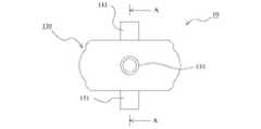
- FIG. 1is a side view of a hollow fiber membrane module according to an embodiment of the invention.
- FIG. 2is a front view of a hollow fiber membrane module according to an example of the present invention.
- FIG. 3is a schematic cross-sectional view of a hollow fiber membrane module according to an example of the present invention.
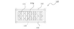
- FIG. 4is a front view of a case body according to an embodiment of the present invention.
- FIG. 5is a plan view of a case body according to an embodiment of the present invention.
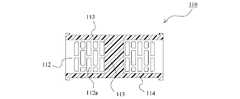
- FIG. 6is a schematic cross-sectional view of a case body according to an embodiment of the invention.
- FIG. 1is a side view of a hollow fiber membrane module according to an embodiment of the invention.
- FIG. 2is a front view of a hollow fiber membrane module according to an example of the present invention.
- FIG. 3is a schematic cross-sectional view of a hollow fiber membrane module according to an example of the present invention, and is a cross-sectional view along AA in FIG.
- FIG. 4is a front view of a case body according to an embodiment of the present invention.
- FIG. 5is a plan view of a case body according to an embodiment of the present invention.
- FIG. 6is a schematic cross-sectional view of the case main body according to the embodiment of the present invention, and is a cross-sectional view along BB in FIG.
- the hollow fiber membrane module 10according to the present embodiment can be applied as a humidifier or a dehumidifier. This point will be briefly explained.
- the hollow fiber membrane module 10has a plurality of hollow fiber membranes 200 inside a case 100 .
- the hollow fiber membrane module 10is configured such that a flow path passing through the outside of the plurality of hollow fiber membranes 200 and a flow path passing through the inside of the membrane are formed.
- the hollow fiber membrane module 10can be suitably used as a humidifier for humidifying the electrolyte membrane provided in the fuel cell.
- moist air generated in the fuel cellis used as the moist gas.
- the humidified gas (air)is used as the humidified gas (air) to the electrolyte membrane provided in the fuel cell.
- the electrolyte membraneis maintained in a wet state.
- the material of the hollow fiber membrane 200for example, PPSU (polyphenylsulfone), etc., which has a property of permeating moisture by a capillary condensation mechanism based on pore size control, can be suitably used.
- the membrane-forming solution(raw material for the hollow fiber membrane)
- spinningis performed using a membrane-forming solution in which PPSU and a hydrophilic polymer (polyvinyl porolidone) are added to the solvent, thereby making the hollow fiber hydrophilic.
- a thread membranecan be obtained.
- Nafionregistered trademark
- the materials described abovehave low elution properties and high strength, and therefore can be suitably used for humidifiers and dehumidifiers.
- the hollow fiber membrane module 10includes a case 100 , a plurality of hollow fiber membranes 200 arranged inside the case 100 , and a pair of sealing fixing portions 310 and 320 .
- the case 100contains a plurality of hollow fiber membranes 200 and includes a resin case body 110 having openings at both ends.
- the case main body 110includes a pair of substantially flat plate portions 111 and 112 and a pair of curved portions 113 and 114 connecting both sides of the pair of substantially flat plate portions 111 and 112, respectively.
- the case body 110is formed of a member having an oval cross section perpendicular to the direction from one end side to the other end side of the case body 110 .
- At least one (in this embodiment, a plurality of) through holes 111a and 112a through which fluid passesare provided in the pair of substantially flat plate portions 111 and 112, respectively.
- the case main body 110has reinforcing portions 115 integrally provided on the pair of wall surfaces that connect a pair of opposed wall surfaces among the inner wall surfaces that accommodate the plurality of hollow fiber membranes 200 .
- this reinforcing portion 115is provided so as to connect the inner wall surfaces of the pair of curved portions 113 and 114 .
- the reinforcing portion 115is located at the center (partial region including the center) between one end side and the other end side of the case body 110 and between the pair of substantially flat plate portions 111 and 112 of the case body 110. It is provided in the center (a part of the area including the center).
- the case body 110 configured as described abovecan be molded by using a resin material such as PSU (polysulfone), PPS (polyphenylene sulfide), and PPA (polyphthalamide). Therefore, the pair of substantially flat plate portions 111 and 112, the pair of curved portions 113 and 114, and the reinforcing portion 115 are integrated.
- the case 100also includes a first fixing member 120 and a second fixing member 130 fixed to both ends of the case main body 110, and a pair of third fixing members 140 provided to cover the pair of substantially flat plate portions 111 and 112, respectively. and a fourth fixing member 150 .
- the method of fixing the first fixing member 120, the second fixing member 130, the third fixing member 140, and the fourth fixing member 150 to the case body 110is not particularly limited, and various known fixing methods such as screw fastening can be used. can be adopted. Further, the first fixing member 120, the second fixing member 130, the third fixing member 140, and the fourth fixing member 150 can also be made of a resin material (resin molded product).
- the first fixing member 120 and the second fixing member 130are provided with pipe portions 121 and 131, respectively, which serve as inlets or outlets for fluid flowing through the inside of the hollow fiber membrane 200 (hollow interior). Further, the third fixing member 140 and the fourth fixing member 150 are provided with tube portions 141 and 151, respectively, which serve as inlets or outlets for fluid flowing outside the hollow fiber membrane 200. As shown in FIG. The third fixing member 140 and the fourth fixing member 140 are arranged so that one of the pipe portions 141 and 151 is arranged on one end side of the case main body 110 and the other is arranged on the other end side of the case main body 110 . The member 150 is fixed to the case body 110 .
- the pair of sealing fixing portions 310 and 320seals the gap between the hollow fiber membranes in a state where the hollow interior of each hollow fiber membrane 200 is opened on both end sides of the case 100, and also seals a plurality of hollow fibers. It is configured to secure the membrane 200 to the case 100 .
- These pair of sealing fixing portions 310 and 320are obtained by curing a potting material such as epoxy resin.
- the hollow fiber membrane module 10configured as described above as a humidifier or a dehumidifier
- the wet gaspasses through the outside of the hollow fiber membrane 200 and reaches the fourth fixing member 150. It flows out of the case 100 from the tube portion 151 (arrow T1).
- the dry gasis supplied from the tube portion 121 of the first fixing member 120 to the inside of the case 100 (dotted line arrow S0)
- the dry gasis supplied from the sealing fixing portion 310 on the one end side to the plurality of hollow fiber membranes 200. It is supplied to each hollow interior and flows through each hollow fiber membrane 200 .
- the dry gasis discharged from the sealing fixing portion 320 on the other end side and flows to the outside of the case 100 from the pipe portion 131 of the second fixing member 130 (arrow S1).
- the membrane separation action of the hollow fiber membrane 200moves the moisture in the wet gas to the dry gas side, humidifies the dry gas, and dehumidifies the wet gas.
- the hollow fiber membrane module 10 of the present embodimentsince the case body 110 is provided with the reinforcing portion 115, even if the fluid pressure in the case body becomes high, the case body 110 is prevented from being deformed. can be suppressed. Therefore, it is possible to suppress the deterioration of the sealing performance and suppress the leakage of the fluid. As a result, deterioration in humidification performance and dehumidification performance can be suppressed.
- the case body 110can be manufactured by mold molding with resin, so the cost can be reduced compared to manufacturing by cutting a metal material. .
- the reinforcing portion 115is provided at the center between the one end side and the other end side of the case body 110 and between the pair of substantially flat plate portions 111 and 112 of the case body 110.
- hollow fiber membrane module100 case 110 case main body 111, 112 flat plate portion 111a, 112a through hole 113, 114 curved portion 115 reinforcing portion 120 first fixing member 121 pipe portion 130 second fixing member 131 pipe portion 140 third fixing member 141 Pipe Part 150 Fourth Fixing Member 151 Pipe Part 200 Hollow Fiber Membrane 310, 320 Seal Fixing Part
Landscapes
- Chemical & Material Sciences (AREA)
- Chemical Kinetics & Catalysis (AREA)
- Engineering & Computer Science (AREA)
- General Chemical & Material Sciences (AREA)
- Life Sciences & Earth Sciences (AREA)
- Manufacturing & Machinery (AREA)
- Sustainable Development (AREA)
- Sustainable Energy (AREA)
- Electrochemistry (AREA)
- Analytical Chemistry (AREA)
- Oil, Petroleum & Natural Gas (AREA)
- Separation Using Semi-Permeable Membranes (AREA)
Abstract
Description
Translated fromJapanese本発明は、加湿装置などに適用可能な中空糸膜モジュールに関する。The present invention relates to a hollow fiber membrane module applicable to humidifiers and the like.
例えば、燃料電池用の加湿装置に備えられる中空糸膜モジュールにおいては、高出力システム向けの需要が高まっており、大型化する傾向にある。大型の中空糸膜モジュールにおいては、ケース内を流れる流体の圧力が高くなる。そのため、大型のケースの場合には、金属などの剛性材料を切削加工することにより製造するのが一般的である。特に、ボックス形状のケースの場合には、流体の圧力により変形し易いため、金属などの剛性材料により構成される。For example, hollow fiber membrane modules installed in humidifiers for fuel cells are in increasing demand for high-output systems, and tend to be larger. In a large-sized hollow fiber membrane module, the fluid flowing inside the case has a high pressure. Therefore, a large case is generally manufactured by cutting a rigid material such as metal. In particular, a box-shaped case is made of a rigid material such as metal because it is easily deformed by fluid pressure.
しかしながら、金属などの剛性材料を切削加工してケースを製造する場合にはコストが高くなる。そこで、金型を用いた樹脂成形によりケースを製造することが望まれるが、大型の中空糸膜モジュールの場合には、上記の通り、流体の圧力が高くなるため、使用中にケースが変形するおそれがある。ケースが変形すると、シール性が低下して、流体漏れが発生してしまい、加湿性能が低下するなど、品質が低下してしまうことが懸念される。However, manufacturing a case by cutting a rigid material such as metal increases the cost. Therefore, it is desirable to manufacture the case by resin molding using a mold, but in the case of a large hollow fiber membrane module, as described above, the fluid pressure increases, so the case deforms during use. There is a risk. If the case is deformed, there is concern that the sealing performance will deteriorate, fluid leakage will occur, and the humidification performance will deteriorate, leading to deterioration in quality.
本発明の目的は、樹脂製のケース本体を採用した場合でも、ケース本体の変形を抑制することのできる中空糸膜モジュールを提供することにある。An object of the present invention is to provide a hollow fiber membrane module capable of suppressing deformation of the case body even when a case body made of resin is employed.
本発明は、上記課題を解決するために以下の手段を採用した。The present invention employs the following means to solve the above problems.
すなわち、本発明の中空糸膜モジュールは、
複数の中空糸膜と、
前記複数の中空糸膜を収容し、かつ両端に開口部を有する樹脂製のケース本体を有するケースと、
前記ケースの両端側において、各中空糸膜の中空内部を開放させた状態で中空糸膜同士の隙間を封止し、かつ前記複数の中空糸膜を前記ケースに固定する一対の封止固定部と、
を備える中空糸膜モジュールであって、
前記ケース本体は、前記複数の中空糸膜を収容する内壁面のうち対向する一対の壁面同士を連結する補強部がこれら一対の壁面に一体に設けられていることを特徴とする。That is, the hollow fiber membrane module of the present invention is
a plurality of hollow fiber membranes;
a case having a resin case body containing the plurality of hollow fiber membranes and having openings at both ends;
A pair of sealing and fixing parts for sealing the gaps between the hollow fiber membranes and fixing the plurality of hollow fiber membranes to the case on both end sides of the case, with the hollow interiors of the hollow fiber membranes being opened. When,
A hollow fiber membrane module comprising
The case main body is characterized in that reinforcing portions for connecting a pair of opposing inner wall surfaces of the inner wall surfaces accommodating the plurality of hollow fiber membranes are integrally provided on the pair of wall surfaces.
本発明によれば、ケース本体に補強部が設けられているため、ケース本体内の流体圧力が高くなっても、ケース本体が変形してしまうことを抑制することができる。According to the present invention, since the case main body is provided with the reinforcing portion, deformation of the case main body can be suppressed even if the fluid pressure in the case main body increases.
前記補強部は前記ケース本体における一端側と他端側との間の中央に設けられているとよい。The reinforcing portion is preferably provided in the center between one end side and the other end side of the case body.
このような構成を採用することで、例えば、補強部を一端側から他端側に至るように設ける場合と比べて、ケース本体内に収容する中空糸膜の充填本数の低下を抑制し、かつ、中空糸膜の膜外を流れる流体の流れが阻害されてしまうことを抑制しつつ、ケース本体の変形を効果的に抑制することができる。By adopting such a configuration, for example, compared with the case where the reinforcing portion is provided so as to extend from one end side to the other end side, a decrease in the number of hollow fiber membranes packed in the case main body is suppressed, and It is possible to effectively suppress deformation of the case body while suppressing obstruction of the flow of fluid flowing outside the hollow fiber membrane.
前記ケース本体は、それぞれ流体が通る少なくとも一つの貫通孔が設けられた一対の略平板部と、これら一対の略平板部の両側をそれぞれ繋ぐ一対の湾曲部とを備え、前記ケース本体の一端側から他端側に向かう方向に対して垂直な断面形状がオーバル形状の部材により構成されており、
前記補強部は前記一対の湾曲部の内壁面同士を連結するように設けられているとよい。The case main body includes a pair of substantially flat plate portions each provided with at least one through hole through which a fluid passes, and a pair of curved portions connecting both sides of the pair of substantially flat plate portions. The cross-sectional shape perpendicular to the direction from to the other end side is composed of an oval-shaped member,
The reinforcing portion may be provided so as to connect inner wall surfaces of the pair of curved portions.
一般的には、このような形状、かつ樹脂製のケース本体は流体圧力によって変形し易いものの、上記の通り、補強部が設けられることで、変形が抑制される。In general, a resin case body with such a shape is easily deformed by fluid pressure, but as described above, the deformation is suppressed by providing the reinforcing part.
前記補強部は前記ケース本体における前記一対の略平板部の間の中央に設けられているとよい。The reinforcing portion is preferably provided in the center between the pair of substantially flat plate portions in the case body.
このような構成を採用することで、例えば、補強部を一対の略平板部に近い付近まで設ける場合と比べて、ケース本体内に収容する中空糸膜の充填本数の低下を抑制し、かつ、中空糸膜の膜外を流れる流体の流れが阻害されてしまうことを抑制しつつ、ケース本体の変形を効果的に抑制することができる。By adopting such a configuration, for example, compared with the case where the reinforcing portion is provided near the pair of substantially flat plate portions, the decrease in the number of hollow fiber membranes packed in the case main body is suppressed, and It is possible to effectively suppress deformation of the case body while suppressing obstruction of the flow of fluid flowing outside the hollow fiber membrane.
なお、上記各構成は、可能な限り組み合わせて採用し得る。It should be noted that each of the above configurations can be employed in combination as much as possible.
以上説明したように、本発明によれば、樹脂製のケース本体を採用した場合でも、ケース本体の変形を抑制することができる。As described above, according to the present invention, deformation of the case body can be suppressed even when a case body made of resin is employed.
以下に図面を参照して、この発明を実施するための形態を、実施例に基づいて例示的に詳しく説明する。ただし、この実施例に記載されている構成部品の寸法、材質、形状、その相対配置などは、特に特定的な記載がない限りは、この発明の範囲をそれらのみに限定する趣旨のものではない。The embodiments for carrying out the present invention will be exemplarily described in detail below with reference to the drawings. However, the dimensions, materials, shapes, relative arrangements, etc. of the components described in this embodiment are not intended to limit the scope of the present invention only to them, unless otherwise specified. .
(実施例)
図1~図6を参照して、本発明の実施例に係る中空糸膜モジュールについて説明する。図1は本発明の実施例に係る中空糸膜モジュールの側面図である。図2は本発明の実施例に係る中空糸膜モジュールの正面図である。図3は本発明の実施例に係る中空糸膜モジュールの模式的断面図であり、図2中のAA断面図である。図4は本発明の実施例に係るケース本体の正面図である。図5は本発明の実施例に係るケース本体の平面図である。図6は本発明の実施例に係るケース本体の模式的断面図であり、図4中のBB断面図である。(Example)
A hollow fiber membrane module according to an embodiment of the present invention will be described with reference to FIGS. 1 to 6. FIG. FIG. 1 is a side view of a hollow fiber membrane module according to an embodiment of the invention. FIG. 2 is a front view of a hollow fiber membrane module according to an example of the present invention. FIG. 3 is a schematic cross-sectional view of a hollow fiber membrane module according to an example of the present invention, and is a cross-sectional view along AA in FIG. FIG. 4 is a front view of a case body according to an embodiment of the present invention. FIG. 5 is a plan view of a case body according to an embodiment of the present invention. FIG. 6 is a schematic cross-sectional view of the case main body according to the embodiment of the present invention, and is a cross-sectional view along BB in FIG.
<中空糸膜モジュールの適用例>
本実施例に係る中空糸膜モジュール10の適用例について説明する。本実施例に係る中空糸膜モジュール10は、加湿装置や除湿装置として適用することができる。この点について簡単に説明する。中空糸膜モジュール10は、ケース100の内部に複数の中空糸膜200が設けられている。そして、中空糸膜モジュール10は、複数の中空糸膜200の膜外を通る流路と、膜内を通る流路が形成されるように構成されている。このような構成により、例えば、中空糸膜200の膜外に湿潤気体を供給し、複数の中空糸膜200の各中空内部に乾燥気体を供給することで、中空糸膜200による膜分離作用によって、湿潤気体中の水分が乾燥気体側に移動する。従って、乾燥気体については加湿され、湿潤気体については除湿されるため、加湿装置としても除湿装置としても利用することができる。<Application example of hollow fiber membrane module>
An application example of the hollow
なお、本実施例に係る中空糸膜モジュール10は、燃料電池に備えられる電解質膜を加湿するための加湿装置として好適に用いることができる。この場合、燃料電池において発生した湿潤空気が、上記の湿潤気体として利用される。そして、加湿された気体(空気)が、燃料電池に備えられる電解質膜に供給されることで、電解質膜については、湿った状態が維持される。ここで、中空糸膜200の素材としては、例えば、孔径制御による毛管凝縮機構により水分を透過する特性を有するPPSU(ポリフェニルスルホン)などを好適に用いることができる。なお、製膜溶液(中空糸膜の原料)を調整する際、溶媒中にPPSUと親水性高分子(ポリビニルポロリドン)を添加した製膜溶液を用いて紡糸を行うことで親水性を有する中空糸膜を得ることができる。また、溶解拡散により水分を透過する特性を有する親水性の材料であるナフィオン(登録商標)を用いることもできる。以上のような材料は、低溶出性であり、かつ強度も高いため、加湿装置や除湿装置に好適に用いることができる。The hollow
<中空糸膜モジュール>
本実施例に係る中空糸膜モジュール10について、より詳細に説明する。中空糸膜モジュール10は、ケース100と、ケース100の内部に配される複数の中空糸膜200と、一対の封止固定部310,320とを備えている。そして、ケース100は、複数の中空糸膜200を収容し、かつ両端に開口部を有する樹脂製のケース本体110を備えている。<Hollow fiber membrane module>
The hollow
ケース本体110は、一対の略平板部111,112と、これら一対の略平板部111,112の両側をそれぞれ繋ぐ一対の湾曲部113,114とを備えている。また、ケース本体110は、ケース本体110の一端側から他端側に向かう方向に対して垂直な断面形状がオーバル形状の部材により構成されている。上記の一対の略平板部111,112には、それぞれ流体が通る少なくとも一つ(本実施例では複数)の貫通孔111a,112aが設けられている。更に、ケース本体110は、複数の中空糸膜200を収容する内壁面のうち対向する一対の壁面同士を連結する補強部115が、これら一対の壁面に一体に設けられている。より具体的には、この補強部115は一対の湾曲部113,114の内壁面同士を連結するように設けられている。そして、この補強部115はケース本体110における一端側と他端側との間の中央(中心を含む一部の領域)であって、ケース本体110における一対の略平板部111,112の間の中央(中心を含む一部の領域)に設けられている。以上のように構成されるケース本体110は、PSU(ポリスルホン)、PPS(ポリフェニレンサルファイド)、及びPPA(ポリフタルアミド)などの樹脂材料を用いて、金型により成形することができる。従って、一対の略平板部111,112と、一対の湾曲部113,114と、補強部115は一体となっている。The case
また、ケース100は、ケース本体110の両端にそれぞれ固定される第1固定部材120及び第2固定部材130と、一対の略平板部111,112をそれぞれ覆うに設けられる一対の第3固定部材140及び第4固定部材150とを備えている。これら第1固定部材120、第2固定部材130、第3固定部材140及び第4固定部材150のケース本体110への固定方法は特に限定されるものではなく、ネジ締結などの各種公知の固定方法を採用することができる。また、これら第1固定部材120、第2固定部材130、第3固定部材140及び第4固定部材150についても、樹脂材料(樹脂成形品)により構成することができる。The
第1固定部材120と第2固定部材130には、中空糸膜200の膜内(中空内部)を流れる流体の入口又は出口となる管部121,131がそれぞれ設けられている。また、第3固定部材140及び第4固定部材150には、中空糸膜200の膜外を流れる流体の入口又は出口となる管部141,151がそれぞれ設けられている。なお、これらの管部141,151のうちの一方がケース本体110の一端側に配されて、他方がケース本体110の他端側に配されるように、第3固定部材140及び第4固定部材150はケース本体110に固定される。The
そして、一対の封止固定部310,320は、ケース100の両端側において、各中空糸膜200の中空内部を開放させた状態で中空糸膜同士の隙間を封止し、かつ複数の中空糸膜200をケース100に固定するように構成されている。これら一対の封止固定部310,320は、エポキシ樹脂などのポッティング材料が硬化することにより得られる。The pair of sealing fixing
以上のように構成される中空糸膜モジュール10を、加湿装置又は除湿装置として適用する場合の一例を図3を参照して説明する。例えば、湿潤気体が第3固定部材140の管部141からケース100の内部に供給されると(矢印T0)、湿潤気体は、中空糸膜200の膜外を通って、第4固定部材150の管部151からケース100の外側に流れていく(矢印T1)。また、乾燥気体が第1固定部材120の管部121からケース100の内部に供給されると(点線矢印S0)、乾燥気体は、一端側の封止固定部310から複数の中空糸膜200の各中空内部に供給されて、それぞれの中空糸膜200の膜内を流れていく。その後、乾燥気体は、他端側の封止固定部320から排出されて、第2固定部材130の管部131からケース100の外側に流れていく(矢印S1)。以上の過程で、中空糸膜200による膜分離作用によって、湿潤気体中の水分が乾燥気体側に移動して、乾燥気体は加湿され、湿潤気体は除湿される。An example of applying the hollow
<本実施例に係る中空糸膜モジュールの優れた点>
本実施例に係る中空糸膜モジュール10によれば、ケース本体110に補強部115が設けられているため、ケース本体内の流体圧力が高くなっても、ケース本体110が変形してしまうことを抑制することができる。従って、シール性の低下を抑制でき、流体の漏れを抑制することができる。これにより、加湿性能や除湿性能の低下を抑制することもできる。また、ケース100の大型化が要求されるような場合でも、ケース本体110を樹脂による金型成形により製造できるため、金属材料の切削加工により製造する場合に比べて、コストを削減することができる。<Excellent Points of the Hollow Fiber Membrane Module According to the Present Example>
According to the hollow
また、本実施例に係る補強部115はケース本体110における一端側と他端側との間の中央であって、ケース本体110における一対の略平板部111,112の間の中央に設けられている。このような構成を採用することで、ケース本体内に収容する中空糸膜200の充填本数の低下を抑制し、かつ、中空糸膜200の膜外を流れる流体の流れが阻害されてしまうことを抑制しつつ、ケース本体110の変形を効果的に抑制することができる。Further, the reinforcing
10 中空糸膜モジュール
100 ケース
110 ケース本体
111,112 平板部
111a,112a 貫通孔
113,114 湾曲部
115 補強部
120 第1固定部材
121 管部
130 第2固定部材
131 管部
140 第3固定部材
141 管部
150 第4固定部材
151 管部
200 中空糸膜
310,320 封止固定部REFERENCE SIGNS
Claims (4)
Translated fromJapanese前記複数の中空糸膜を収容し、かつ両端に開口部を有する樹脂製のケース本体を有するケースと、
前記ケースの両端側において、各中空糸膜の中空内部を開放させた状態で中空糸膜同士の隙間を封止し、かつ前記複数の中空糸膜を前記ケースに固定する一対の封止固定部と、
を備える中空糸膜モジュールであって、
前記ケース本体は、前記複数の中空糸膜を収容する内壁面のうち対向する一対の壁面同士を連結する補強部がこれら一対の壁面に一体に設けられていることを特徴とする中空糸膜モジュール。a plurality of hollow fiber membranes;
a case having a resin case body containing the plurality of hollow fiber membranes and having openings at both ends;
A pair of sealing and fixing parts for sealing the gaps between the hollow fiber membranes and fixing the plurality of hollow fiber membranes to the case on both end sides of the case, with the hollow interiors of the hollow fiber membranes being opened. When,
A hollow fiber membrane module comprising
The hollow fiber membrane module, wherein the case body has a reinforcing portion integrally provided on the pair of inner wall surfaces for connecting the pair of inner wall surfaces facing each other among the inner wall surfaces accommodating the plurality of hollow fiber membranes. .
前記補強部は前記一対の湾曲部の内壁面同士を連結するように設けられていることを特徴とする請求項1又は2に記載の中空糸膜モジュール。The case main body includes a pair of substantially flat plate portions each provided with at least one through hole through which a fluid passes, and a pair of curved portions connecting both sides of the pair of substantially flat plate portions. The cross-sectional shape perpendicular to the direction from to the other end side is composed of an oval-shaped member,
3. The hollow fiber membrane module according to claim 1, wherein the reinforcing portion is provided so as to connect inner wall surfaces of the pair of curved portions.
4. The hollow fiber membrane module according to claim 3, wherein the reinforcing portion is provided in the center between the pair of substantially flat plate portions in the case body.
Priority Applications (6)
| Application Number | Priority Date | Filing Date | Title |
|---|---|---|---|
| CA3214464ACA3214464A1 (en) | 2021-06-02 | 2022-05-17 | Hollow fiber membrane module |
| KR1020237031388AKR20230146064A (en) | 2021-06-02 | 2022-05-17 | hollow desert module |
| US18/282,960US20240181395A1 (en) | 2021-06-02 | 2022-05-17 | Hollow fiber membrane module |
| JP2023525708AJP7607122B2 (en) | 2021-06-02 | 2022-05-17 | Hollow fiber membrane module |
| CN202280021423.4ACN117015431A (en) | 2021-06-02 | 2022-05-17 | Hollow fiber membrane module |
| EP22815838.2AEP4349466A4 (en) | 2021-06-02 | 2022-05-17 | Hollow fiber membrane module |
Applications Claiming Priority (2)
| Application Number | Priority Date | Filing Date | Title |
|---|---|---|---|
| JP2021092809 | 2021-06-02 | ||
| JP2021-092809 | 2021-06-02 |
Publications (1)
| Publication Number | Publication Date |
|---|---|
| WO2022255086A1true WO2022255086A1 (en) | 2022-12-08 |
Family
ID=84323227
Family Applications (1)
| Application Number | Title | Priority Date | Filing Date |
|---|---|---|---|
| PCT/JP2022/020494CeasedWO2022255086A1 (en) | 2021-06-02 | 2022-05-17 | Hollow fiber membrane module |
Country Status (7)
| Country | Link |
|---|---|
| US (1) | US20240181395A1 (en) |
| EP (1) | EP4349466A4 (en) |
| JP (1) | JP7607122B2 (en) |
| KR (1) | KR20230146064A (en) |
| CN (1) | CN117015431A (en) |
| CA (1) | CA3214464A1 (en) |
| WO (1) | WO2022255086A1 (en) |
Cited By (4)
| Publication number | Priority date | Publication date | Assignee | Title |
|---|---|---|---|---|
| WO2024176959A1 (en)* | 2023-02-21 | 2024-08-29 | Nok株式会社 | Hollow fiber membrane module |
| WO2024176963A1 (en)* | 2023-02-21 | 2024-08-29 | Nok株式会社 | Hollow fiber membrane module |
| WO2024176970A1 (en)* | 2023-02-21 | 2024-08-29 | Nok株式会社 | Hollow fiber membrane module |
| WO2024218027A1 (en)* | 2023-04-21 | 2024-10-24 | Basf Se | Hollow fiber membranes comprising a poly(aryl ether sulfone) and a water-soluble polymer additive |
Families Citing this family (1)
| Publication number | Priority date | Publication date | Assignee | Title |
|---|---|---|---|---|
| KR20230035982A (en)* | 2021-09-06 | 2023-03-14 | 코오롱인더스트리 주식회사 | Cartridge for membrane humidifier and fuel cell humidifier comprising it |
Citations (6)
| Publication number | Priority date | Publication date | Assignee | Title |
|---|---|---|---|---|
| JPH0259016A (en)* | 1988-08-25 | 1990-02-28 | Ube Ind Ltd | gas separation membrane module |
| JP2002303435A (en)* | 2001-03-30 | 2002-10-18 | Honda Motor Co Ltd | Humidification module |
| JP2005040675A (en)* | 2003-07-24 | 2005-02-17 | Nok Corp | Hollow fiber membrane module |
| WO2006112142A1 (en)* | 2005-04-13 | 2006-10-26 | Nok Corporation | Hollow fiber membrane module and method of manufacturing the same |
| JP2015226859A (en)* | 2012-10-05 | 2015-12-17 | Nok株式会社 | Case for hollow fiber membrane module |
| WO2020026875A1 (en)* | 2018-07-30 | 2020-02-06 | Nok株式会社 | Hollow fiber membrane module |
Family Cites Families (17)
| Publication number | Priority date | Publication date | Assignee | Title |
|---|---|---|---|---|
| US2850890A (en)* | 1951-06-04 | 1958-09-09 | Rubenstein David | Precast element and reinforced facing layer bonded thereto |
| US4289623A (en)* | 1975-11-05 | 1981-09-15 | Extracorporeal Medical Specialties, Inc. | Hollow fiber dialysis |
| DE3586677T2 (en)* | 1984-11-29 | 1993-03-11 | Asahi Chemical Ind | METHOD FOR PRODUCING A SEMIPERMEABLED HOLLOW FIBER MEMBRANE ELEMENT AND A SEMIPERMEABLE HOLLOW FIBER MEMBRANE ELEMENT. |
| US5334429A (en)* | 1991-06-24 | 1994-08-02 | Ashimori Industry Co., Ltd. | Lining material for pipe lines and a process for providing pipe lines therewith |
| US5472607A (en)* | 1993-12-20 | 1995-12-05 | Zenon Environmental Inc. | Hollow fiber semipermeable membrane of tubular braid |
| US20020006090A1 (en)* | 2000-07-14 | 2002-01-17 | Tdk Corporation | Objective lens drive apparatus for use in optical pickup |
| US7081484B2 (en)* | 2000-07-24 | 2006-07-25 | Asahi Glass Company, Limited | Anion exchange membrane, process for its production and solution treating apparatus |
| US20030012090A1 (en)* | 2001-07-12 | 2003-01-16 | Tdk Corporation | Objective lens drive apparatus for use in optical pickup |
| BRPI0919633B1 (en)* | 2008-11-18 | 2019-09-10 | Mitsubishi Heavy Ind Ltd | method and device for the manufacture of composite material |
| KR101185326B1 (en)* | 2010-03-31 | 2012-09-26 | 코오롱인더스트리 주식회사 | Humidifier for fuel cell |
| US8771452B2 (en)* | 2010-08-27 | 2014-07-08 | Toyota Jidosha Kabushiki Kaisha | Process for producing fiber-reinforced resin material |
| EP3041927B1 (en)* | 2013-09-06 | 2018-02-28 | GE Healthcare Bio-Sciences AB | Cell culture bag with internal dialysis membrane |
| KR102098641B1 (en)* | 2015-06-22 | 2020-04-08 | 코오롱인더스트리 주식회사 | Hollow Fiber Membrane Humidifier Module |
| EP3456405A4 (en)* | 2016-05-11 | 2020-01-22 | Mitsubishi Chemical Cleansui Corporation | HOLLOW FIBER MEMBRANE MODULE |
| KR101883070B1 (en)* | 2016-10-25 | 2018-07-27 | 삼성전기주식회사 | Inductor |
| JP2018190147A (en) | 2017-05-01 | 2018-11-29 | 株式会社アスカネット | Funeral letter delivery system and funeral return |
| US20230398748A1 (en)* | 2022-06-08 | 2023-12-14 | Spirit Aerosystems, Inc. | Semi-conformable pressure application system and method for joining composite parts |
- 2022
- 2022-05-17WOPCT/JP2022/020494patent/WO2022255086A1/ennot_activeCeased
- 2022-05-17JPJP2023525708Apatent/JP7607122B2/enactiveActive
- 2022-05-17KRKR1020237031388Apatent/KR20230146064A/enactivePending
- 2022-05-17EPEP22815838.2Apatent/EP4349466A4/enactivePending
- 2022-05-17USUS18/282,960patent/US20240181395A1/enactivePending
- 2022-05-17CNCN202280021423.4Apatent/CN117015431A/enactivePending
- 2022-05-17CACA3214464Apatent/CA3214464A1/enactivePending
Patent Citations (6)
| Publication number | Priority date | Publication date | Assignee | Title |
|---|---|---|---|---|
| JPH0259016A (en)* | 1988-08-25 | 1990-02-28 | Ube Ind Ltd | gas separation membrane module |
| JP2002303435A (en)* | 2001-03-30 | 2002-10-18 | Honda Motor Co Ltd | Humidification module |
| JP2005040675A (en)* | 2003-07-24 | 2005-02-17 | Nok Corp | Hollow fiber membrane module |
| WO2006112142A1 (en)* | 2005-04-13 | 2006-10-26 | Nok Corporation | Hollow fiber membrane module and method of manufacturing the same |
| JP2015226859A (en)* | 2012-10-05 | 2015-12-17 | Nok株式会社 | Case for hollow fiber membrane module |
| WO2020026875A1 (en)* | 2018-07-30 | 2020-02-06 | Nok株式会社 | Hollow fiber membrane module |
Non-Patent Citations (1)
| Title |
|---|
| See also references ofEP4349466A4* |
Cited By (4)
| Publication number | Priority date | Publication date | Assignee | Title |
|---|---|---|---|---|
| WO2024176959A1 (en)* | 2023-02-21 | 2024-08-29 | Nok株式会社 | Hollow fiber membrane module |
| WO2024176963A1 (en)* | 2023-02-21 | 2024-08-29 | Nok株式会社 | Hollow fiber membrane module |
| WO2024176970A1 (en)* | 2023-02-21 | 2024-08-29 | Nok株式会社 | Hollow fiber membrane module |
| WO2024218027A1 (en)* | 2023-04-21 | 2024-10-24 | Basf Se | Hollow fiber membranes comprising a poly(aryl ether sulfone) and a water-soluble polymer additive |
Also Published As
| Publication number | Publication date |
|---|---|
| JP7607122B2 (en) | 2024-12-26 |
| JPWO2022255086A1 (en) | 2022-12-08 |
| US20240181395A1 (en) | 2024-06-06 |
| EP4349466A4 (en) | 2025-04-30 |
| KR20230146064A (en) | 2023-10-18 |
| EP4349466A1 (en) | 2024-04-10 |
| CN117015431A (en) | 2023-11-07 |
| CA3214464A1 (en) | 2022-12-08 |
Similar Documents
| Publication | Publication Date | Title |
|---|---|---|
| WO2022255086A1 (en) | Hollow fiber membrane module | |
| CN111683730B (en) | Hollow Fiber Membrane Module | |
| JP7638372B2 (en) | Hollow fiber membrane module and dehumidification/humidification device | |
| WO2018190147A1 (en) | Hollow fiber membrane module | |
| JP7685049B2 (en) | Hollow fiber membrane module and dehumidification/humidification device | |
| US20240173675A1 (en) | Hollow fiber membrane module and dehumidification/humidification device | |
| US20240375052A1 (en) | Hollow fiber membrane module | |
| JP7625698B2 (en) | Hollow fiber membrane module | |
| WO2024176970A1 (en) | Hollow fiber membrane module | |
| WO2024176959A1 (en) | Hollow fiber membrane module | |
| WO2024176963A1 (en) | Hollow fiber membrane module | |
| JP2018199098A (en) | Membrane separator |
Legal Events
| Date | Code | Title | Description |
|---|---|---|---|
| 121 | Ep: the epo has been informed by wipo that ep was designated in this application | Ref document number:22815838 Country of ref document:EP Kind code of ref document:A1 | |
| ENP | Entry into the national phase | Ref document number:20237031388 Country of ref document:KR Kind code of ref document:A | |
| WWE | Wipo information: entry into national phase | Ref document number:202280021423.4 Country of ref document:CN Ref document number:1020237031388 Country of ref document:KR | |
| WWE | Wipo information: entry into national phase | Ref document number:18282960 Country of ref document:US | |
| ENP | Entry into the national phase | Ref document number:3214464 Country of ref document:CA | |
| WWE | Wipo information: entry into national phase | Ref document number:2023525708 Country of ref document:JP | |
| WWE | Wipo information: entry into national phase | Ref document number:2022815838 Country of ref document:EP | |
| NENP | Non-entry into the national phase | Ref country code:DE | |
| ENP | Entry into the national phase | Ref document number:2022815838 Country of ref document:EP Effective date:20240102 |