WO2022244149A1 - Ion milling device - Google Patents
Ion milling deviceDownload PDFInfo
- Publication number
- WO2022244149A1 WO2022244149A1PCT/JP2021/019012JP2021019012WWO2022244149A1WO 2022244149 A1WO2022244149 A1WO 2022244149A1JP 2021019012 WJP2021019012 WJP 2021019012WWO 2022244149 A1WO2022244149 A1WO 2022244149A1
- Authority
- WO
- WIPO (PCT)
- Prior art keywords
- ion beam
- ion
- sample
- profile
- cathode
- Prior art date
- Legal status (The legal status is an assumption and is not a legal conclusion. Google has not performed a legal analysis and makes no representation as to the accuracy of the status listed.)
- Ceased
Links
Images


Classifications
- H—ELECTRICITY
- H01—ELECTRIC ELEMENTS
- H01J—ELECTRIC DISCHARGE TUBES OR DISCHARGE LAMPS
- H01J37/00—Discharge tubes with provision for introducing objects or material to be exposed to the discharge, e.g. for the purpose of examination or processing thereof
- H01J37/30—Electron-beam or ion-beam tubes for localised treatment of objects
- H01J37/305—Electron-beam or ion-beam tubes for localised treatment of objects for casting, melting, evaporating, or etching
- H01J37/3053—Electron-beam or ion-beam tubes for localised treatment of objects for casting, melting, evaporating, or etching for evaporating or etching
- H—ELECTRICITY
- H01—ELECTRIC ELEMENTS
- H01J—ELECTRIC DISCHARGE TUBES OR DISCHARGE LAMPS
- H01J27/00—Ion beam tubes
- H01J27/02—Ion sources; Ion guns
- H01J27/16—Ion sources; Ion guns using high-frequency excitation, e.g. microwave excitation
- H01J27/18—Ion sources; Ion guns using high-frequency excitation, e.g. microwave excitation with an applied axial magnetic field
- H—ELECTRICITY
- H01—ELECTRIC ELEMENTS
- H01J—ELECTRIC DISCHARGE TUBES OR DISCHARGE LAMPS
- H01J29/00—Details of cathode-ray tubes or of electron-beam tubes of the types covered by group H01J31/00
- H01J29/84—Traps for removing or diverting unwanted particles, e.g. negative ions, fringing electrons; Arrangements for velocity or mass selection
- H—ELECTRICITY
- H01—ELECTRIC ELEMENTS
- H01J—ELECTRIC DISCHARGE TUBES OR DISCHARGE LAMPS
- H01J37/00—Discharge tubes with provision for introducing objects or material to be exposed to the discharge, e.g. for the purpose of examination or processing thereof
- H01J37/02—Details
- H01J37/04—Arrangements of electrodes and associated parts for generating or controlling the discharge, e.g. electron-optical arrangement or ion-optical arrangement
- H01J37/08—Ion sources; Ion guns
- H—ELECTRICITY
- H01—ELECTRIC ELEMENTS
- H01J—ELECTRIC DISCHARGE TUBES OR DISCHARGE LAMPS
- H01J37/00—Discharge tubes with provision for introducing objects or material to be exposed to the discharge, e.g. for the purpose of examination or processing thereof
- H01J37/02—Details
- H01J37/24—Circuit arrangements not adapted to a particular application of the tube and not otherwise provided for
- H01J37/243—Beam current control or regulation circuits
- H—ELECTRICITY
- H01—ELECTRIC ELEMENTS
- H01J—ELECTRIC DISCHARGE TUBES OR DISCHARGE LAMPS
- H01J37/00—Discharge tubes with provision for introducing objects or material to be exposed to the discharge, e.g. for the purpose of examination or processing thereof
- H01J37/02—Details
- H01J37/244—Detectors; Associated components or circuits therefor
- H—ELECTRICITY
- H01—ELECTRIC ELEMENTS
- H01J—ELECTRIC DISCHARGE TUBES OR DISCHARGE LAMPS
- H01J37/00—Discharge tubes with provision for introducing objects or material to be exposed to the discharge, e.g. for the purpose of examination or processing thereof
- H01J37/26—Electron or ion microscopes; Electron or ion diffraction tubes
- H01J37/261—Details
- H01J37/265—Controlling the tube; circuit arrangements adapted to a particular application not otherwise provided, e.g. bright-field-dark-field illumination
- H—ELECTRICITY
- H01—ELECTRIC ELEMENTS
- H01J—ELECTRIC DISCHARGE TUBES OR DISCHARGE LAMPS
- H01J37/00—Discharge tubes with provision for introducing objects or material to be exposed to the discharge, e.g. for the purpose of examination or processing thereof
- H01J37/30—Electron-beam or ion-beam tubes for localised treatment of objects
- H01J37/304—Controlling tubes by information coming from the objects or from the beam, e.g. correction signals
- H—ELECTRICITY
- H01—ELECTRIC ELEMENTS
- H01J—ELECTRIC DISCHARGE TUBES OR DISCHARGE LAMPS
- H01J37/00—Discharge tubes with provision for introducing objects or material to be exposed to the discharge, e.g. for the purpose of examination or processing thereof
- H01J37/30—Electron-beam or ion-beam tubes for localised treatment of objects
- H01J37/305—Electron-beam or ion-beam tubes for localised treatment of objects for casting, melting, evaporating, or etching
- H—ELECTRICITY
- H01—ELECTRIC ELEMENTS
- H01J—ELECTRIC DISCHARGE TUBES OR DISCHARGE LAMPS
- H01J2237/00—Discharge tubes exposing object to beam, e.g. for analysis treatment, etching, imaging
- H01J2237/245—Detection characterised by the variable being measured
- H01J2237/24507—Intensity, dose or other characteristics of particle beams or electromagnetic radiation
- H01J2237/24514—Beam diagnostics including control of the parameter or property diagnosed
- H01J2237/24542—Beam profile
- H—ELECTRICITY
- H01—ELECTRIC ELEMENTS
- H01J—ELECTRIC DISCHARGE TUBES OR DISCHARGE LAMPS
- H01J2237/00—Discharge tubes exposing object to beam, e.g. for analysis treatment, etching, imaging
- H01J2237/30—Electron or ion beam tubes for processing objects
- H01J2237/31—Processing objects on a macro-scale
- H01J2237/3151—Etching
Definitions
- the present inventionrelates to an ion milling device suitable for pretreatment processing of samples observed with an electron microscope.
- the ion milling methodis a processing method in which accelerated ions collide with the sample, and the sample is milled using the sputtering phenomenon in which the ions repel atoms and molecules.
- This methodis used for metals, glasses, ceramics, electronic parts, composite materials, etc.
- electronic partsit is used for internal structure, cross-sectional area shape, film thickness evaluation, crystal state, failure and foreign matter cross-section analysis.
- itis widely used as a cross-sectional sample preparation method for obtaining morphological images, sample composition images, channeling images by scanning electron microscope, X-ray analysis, crystal orientation analysis, etc.
- the scope of applicationhas been expanded to structure observation for the purpose of process control in mass production processes in the field of semiconductors and the like.
- a small Penning discharge ion gun with a simple configurationis used as the ion gun.
- the Penning discharge type ion gunelectrons emitted from the cathode are ionized by rotating due to the magnetic field of the permanent magnet and colliding with the process gas introduced into the ion gun.
- the electrons that are orbiting due to the magnetic fieldreciprocate between the cathodes, thereby lengthening the electron trajectory and improving the ionization efficiency. .
- Thishas the advantage that a high plasma density can be obtained.
- a high plasma densityis essential for this purpose, and it is important to supply an appropriate magnetic field strength on the ion gun axis. Fluctuations in the magnetic field intensity cause a decrease in plasma density, affect the ion beam performance, and change the processing shape of the sample processing surface.
- the ion milling deviceprocesses the sample by irradiating the sample surface with an unfocused ion beam emitted from a Penning discharge type ion gun.
- the ion density distribution of the non-focused ion beamhas the characteristic that it is highest at the irradiation center and decreases toward the outside. Since the ion density is closely related to the processing speed of the sample, the ion density distribution is directly reflected in the processing shape of the sample processing surface. Therefore, when the ion milling apparatus is used for pretreatment processing of a sample to be observed with an electron microscope, the difference in ion density distribution is directly linked to the difference in the observation surface observed with the electron microscope.
- Patent Document 1discloses the basic structure of a Penning discharge ion gun.
- Patent Literature 2discloses a Penning discharge type ion gun that achieves a higher processing speed than conventional ion guns by limiting the magnetic field intensity of the built-in magnet to an appropriate value.
- An ion milling apparatuswhich is an embodiment of the present invention, comprises a vacuum chamber whose internal air pressure is controlled by a vacuum exhaust system, an ion gun attached to the vacuum chamber for irradiating an unfocused ion beam, and It has a sample stage for holding a sample, an ion beam characteristic measurement mechanism for measuring ion beam characteristics for estimating the processing profile of the sample by the ion beam, and a controller, and applies a magnetic field to the ionization chamber of the ion gun.
- the magnetic field generator to be generatedis an electromagnet having an electromagnetic coil and a magnetic path, and the controller controls the current value applied to the electromagnetic coil based on the ion beam characteristics measured by the ion beam characteristics measuring mechanism.
- FIG. 1is a schematic diagram (cross-sectional view) of an ion beam and a sample processed by the ion beam;
- FIG. 2is a schematic diagram (top view) of a sample processed by an ion beam; It is a figure which shows the relationship between the axial magnetic flux density of an ion gun, and a milling processing speed.
- FIG. 5is a diagram schematically showing how the machining depth and machining shape fluctuate under the influence of on-axis magnetic flux density;
- FIG. 5is a diagram showing an example profile of on-axis magnetic flux density;
- 5is a diagram showing an example profile of on-axis magnetic flux density; It is an ion beam profile measured by an ion beam characteristic measuring mechanism. 4 is a flowchart for adjusting ion beam irradiation conditions; It is another configuration example of the ion milling device. It is another configuration example of the ion milling device.
- FIG. 1is a schematic diagram showing the main part of the ion milling device 300 of this embodiment.
- a Penning discharge type ion gun 1comprises elements necessary for generating ions therein, and irradiates a sample 6 with an ion beam 2 . Its internal structure will be described later.
- a gas source 41is connected to the ion gun 1 through a gas supply mechanism 40 , and a gas flow rate controlled by the gas supply mechanism 40 is supplied into the plasma generation chamber of the ion gun 1 .
- the gas supply mechanism 40includes all components for adjusting the flow rate of the gas to be ionized and supplying it inside the ion gun.
- Ar gasis used as an introduced gas, for example.
- Irradiation conditions of the ion beam 2are controlled by the ion gun controller 3 .
- the ion gun control unit 3includes all components for adjusting the voltage conditions applied to the components of the ion gun 1 and emitting the ion beam 2 .
- the vacuum chamber 4is controlled to atmospheric pressure or vacuum by an evacuation system 5 .
- a sample 6is held on a sample stage 7 , and the sample stage 7 is held by a sample stage 8 .
- a sample stage drive unit 9is provided to drive the sample stage 8 .
- the sample 6is irradiated with the ion beam 2 emitted from the ion gun 1 without being focused. Therefore, the ion beam distribution near the ion beam irradiation point of the sample 6 has the highest ion density in the central portion. , the ion density decreases from the center toward the outside. Since the ion density is directly linked to the processing speed of the sample, the processed shape of the sample greatly depends on the ion beam distribution near the ion beam irradiation point.
- the ion milling apparatus 300has means for measuring the intensity distribution of the unfocused ion beam from the ion gun 1 (ion beam characteristic measuring mechanism) for the purpose of improving processing speed controllability and processing profile reproducibility.
- a current probe 52is arranged between the ion gun 1 and the sample 6, and the ion beam current value of the ion beam 2 is measured by the ammeter 50.
- FIG. The ammeter 50includes all components for outputting ion information captured by a current probe 52 irradiated with the ion beam 2 as a current value.
- the current probe 52is a linear conductive member extending in the Y direction, and is reciprocally driven in the X direction perpendicular to the Y direction in the figure by the current probe driving unit 51 .
- the trajectory of the current probe 52can be determined. It is possible to obtain an intensity distribution of the ion beam current (hereinafter referred to as an ion beam profile) along the .
- the ion milling device 300is controlled by the device control section 200 .
- a display unit 210 and an input unit 220 for inputting a user's instructionare connected to the device control unit 200 .
- the device control unit 200is connected to control mechanisms of various parts of the ion milling device such as the ion gun control unit 3, the vacuum exhaust system 5, the gas supply mechanism 40, the coil control unit 62, and the sample stage drive unit 9. ing. It is also connected to a monitor mechanism such as an ammeter 50 that monitors the operational status of the ion milling apparatus.
- the display unit 210displays the ion beam profile obtained from the output of the ammeter 50, as well as the control parameters and operating state of the device. Before milling the actual device, the user checks the ion beam profile of the ion beam 2 and adjusts the control parameters of the ion gun 1 through the input unit 220 so as to obtain the desired ion beam characteristics. can do. Further, an operation program for adjusting the control parameters may be executed based on the monitoring result of the monitoring mechanism of the ion milling apparatus 300 including the ion beam characteristic measuring mechanism.
- the main control parameters for adjusting the ion beam characteristicsare the discharge voltage and the gas flow rate, and the inventors' examination revealed that adjustment by these control parameters alone is insufficient. .
- a parameter that greatly affects the ion beam intensityis the on-axis magnetic flux density.
- a conventional Penning discharge ion gunuses a permanent magnet to generate a magnetic field. Due to the nature of permanent magnets, the magnetic field strength cannot be controlled and individual differences are large. It is difficult to cancel variations in axial magnetic flux density due to individual differences in permanent magnets by adjusting the discharge voltage and gas flow rate. For this reason, the conventional ion milling apparatus has a large machine difference, and has inevitably been insufficient in machining speed controllability and machining profile reproducibility.
- the on-axis magnetic field density of the ion gun 1can be controlled in order to satisfy the advanced processing speed controllability and processing profile reproducibility required for mass production management. Therefore, the magnetic field generator of the ion gun 1 is of an electromagnet type having an electromagnetic coil 61, a magnetic path 60, and a coil control section 62, and the on-axis magnetic flux density of the ion gun 1 can be adjusted by the coil current.
- the coil controller 62contains all the components for adjusting the current applied to the electromagnetic coil 61 to provide the ion gun 1 with the proper axial magnetic flux density.
- the current value of the electromagnetic coil 61is newly added as a control parameter for adjusting the ion beam characteristics, making it possible to control the on-axis magnetic flux density. can be significantly increased.
- FIG. 2is a cross-sectional view showing the configuration of the ion gun 1 and related peripheral parts.
- the first cathode 11is made of a conductive magnetic material such as pure iron and has a disc shape, and is provided with a hole for introducing gas into the ionization chamber 18 .
- the second cathode 12is made of a conductive magnetic material such as pure iron and formed in a disc shape, and has a cathode exit hole in the center.
- the first cathode 11 and the second cathode 12are each connected to a cathode ring 14 and arranged to face each other.
- a cylindrical insulator 16is arranged inside the cathode ring 14 .
- the anode 13is fitted inside the insulator 16 , the outer surface of the anode 13 is in contact with the inner surface of the insulator 16 and the inner surface faces the ionization chamber 18 .
- the anode 13is made of a conductive non-magnetic material such as aluminum.
- Anode 13is electrically insulated from first cathode 11 and second cathode 12 and cathode ring 14 by insulator 16 .
- the accelerating electrode 15is made of a conductive non-magnetic material such as stainless steel, and has an accelerating electrode exit hole in the center.
- the magnetic field generating device of the ion gun 1is an electromagnet system that includes an electromagnetic coil 61, a magnetic path 60, and a coil control section 62.
- the electromagnetic coil 61is provided outside the vacuum chamber 4 and on the outer peripheral portion of the ion gun base 17 . An opening is provided to surround the ring 14 . It should be noted that the electromagnetic coil 61 generates heat by applying a current to the electromagnetic coil 61 . By arranging the electromagnetic coil 61 outside the vacuum chamber 4, heat dissipation from the electromagnetic coil 61 can be facilitated.
- the gas supply mechanism 40is connected to the ion gun base 17 and includes all components for adjusting the flow rate of the gas to be ionized and supplying it inside the ion gun.
- Ar gaswill be described as an example.
- a holeis provided in the ion gun base 17 and the cathode 11 , and Ar gas introduced from the gas supply mechanism 40 is introduced into the ionization chamber 18 .
- the Ar gas introduced into the ionization chamber 18is maintained at an appropriate gas partial pressure, and a discharge voltage of about 0 to 4 kV is applied between the first cathode 11, the second cathode 12 and the anode 13 by the discharge power supply 21. is applied, electrons are generated due to the potential difference between the anode and the cathode.
- the generated electronsare bent by the magnetic field formed by the electromagnetic coil 61 and the magnetic path 60 and undergo a revolving motion.
- an accelerating voltage of about 0 to 10 kVis applied between the cathode 12 and the accelerating electrode 15 by the accelerating power source 22 to accelerate the Ar ions and eject the ion beam 2 out of the ion gun 1 .
- some of the positive ions generated in the ionization chamber 18pass through the cathode exit hole of the second cathode 12, are accelerated by the accelerating electrode 15, and are emitted from the accelerating electrode exit hole to the outside of the ion gun 1.
- a sample 6is processed by an ion beam 2 composed of ions.
- FIGS. 3A and 3Bshow schematic diagrams of the ion beam 2 emitted from the ion gun 1 and the sample 6 processed by it.
- 3Ais a sectional view of the ion gun 1, the ion beam 2, and the sample 6, and FIG. 3B is a top view of the sample 6.
- FIG. 3Athe ion beam 2 emitted from the ion gun 1 irradiates the sample 6 without being focused, so that it is formed in a Gaussian distribution around the beam center 105 . For this reason, the ion beam distribution at the ion beam irradiation point of the sample 6 has the characteristic that the ion density is highest in the central portion and decreases toward the outside from the center.
- the ion densityis directly linked to the processing speed of the sample, and the milling processing area 100 on the surface of the sample 6 has the largest processing amount at the center of the ion beam irradiation, and has a shape in which the processing amount decreases from the center toward the outside.
- the milling region 100may vary depending on the processing depth and inclination angle of the milling region 100.
- the shape of the exposed measurement pattern 101changes. In order to obtain accurate evaluation results, high precision is required for the reproducibility of the machined shape.
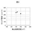
- FIG. 4is a diagram showing the relationship between the milling speed and the on-axis magnetic flux density of the ion gun.
- an ion gun using a permanent magnet as a magnetic field generatorwas used, and the applied milling conditions were an acceleration voltage condition of 6 kV, a discharge voltage of 1.5 kV, an Ar gas as the gas introduced into the ion gun, and a flow rate of It was 0.07 cm 3 /min.
- the material to be processedwas silicon, and as shown in FIG. 3A, the surface of the sample 6 was irradiated with the ion beam 2 perpendicularly, and the milling time was set to 1 hour. As can be seen from FIG.
- the milling speedis 360 ⁇ m/hr, increases to 385 ⁇ m/hr at 145 mT, and decreases to 340 ⁇ m/hr at 160 mT.
- the on-axis magnetic flux density of the ion gun 1is a factor that greatly affects the milling speed, that is, the ion beam intensity.
- the magnetic field generating deviceis a permanent magnet, such individual differences result in machine differences, resulting in lower reproducibility.
- the performance of the permanent magnetis deteriorated due to heating.
- the magnetic field generator of the ion gun 1is a permanent magnet
- the axial magnetic flux densityvaries greatly due to individual differences and deterioration over time. Fluctuations in ion beam properties due to magnetic flux density may not be corrected by other control parameters.
- FIG. 5schematically shows how the machining depth and machining shape change due to the influence of the on-axis magnetic flux density in the Penning discharge type ion gun 1 .
- the on-axis magnetic flux densityaffects the orbital motion of electrons generated in the ionization chamber 18 .
- the diameter of the electron rotationis changed by the on-axis magnetic flux density, the spread of the plasma region and the plasma density are affected, and the ion beam characteristics are varied.
- This influenceaffects the spread of the ion beam 115 as shown in FIG. 5, and the processing profile 125 also fluctuates.
- the machining profile 125 of the milling process area 100cannot be formed with high reproducibility, the shape of the measurement pattern 101 that appears changes, and this cannot be applied to mass production process control. .
- FIG. 6Ais the profile of the axial magnetic flux density when the current value applied to the electromagnetic coil 61 is 2.6 A, and the maximum magnetic field is 350 mT.
- FIG. 6Bshows the profile of the axial magnetic flux density when the current value applied to the electromagnetic coil 61 is 3.7 A, and the maximum magnetic field is 500 mT.
- the range indicated by the arrows in both magnetic field profilescorresponds to the ionization chamber 18 .
- the magnetic field profile in the ionization chamber 18has a similar shape, and it can be seen that an increase in the current value lifts the magnetic field profile in the direction of high density without changing the shape of the magnetic field profile. From this, it can be seen that ion beam profile control by adjusting the on-axis magnetic flux density is effective.
- the ion milling apparatus 300has an ion beam characteristic measuring mechanism in order to control the ion beam characteristic by adjusting the axial magnetic flux density of the ion gun.
- FIG. 7shows an ion beam profile measured by the current probe 52. As shown in FIG. The horizontal axis indicates the beam measurement position, and the vertical axis indicates the ion beam current measured by the current probe 52 .
- the ion beam profile to be measuredis the sum of the ion beam profile flowing due to Ar ions colliding with the current probe 52 and the background noise profile due to electrons generated due to the irradiation of the ion beam. Therefore, it is necessary to remove the effect of the background noise profile from the measured ion beam profile.
- the background noise profilefluctuates depending on the measurement position due to variations in the generation of secondary electrons and backscattered electrons and differences in the amount of electron collision with the current probe 52 depending on the beam measurement position. Secondary electrons and backscattered electrons generated by Ar ion collisions have negative charges. A voltage is applied to electron trap 55 .
- An electron trap driver 54is provided to move the electron trap 55 so that the electron trap 55 does not block the ion beam 2 during processing of the sample 6 . Also, in order to prevent the electron trap 55 from becoming a source of noise due to collision of ions, it is desirable to use a light element and low sputtering yield material for the electron trap 55 . Specifically, it is desirable to use graphite carbon.
- the device control unit 200evacuates the vacuum chamber 4 by the vacuum exhaust system 5 .
- a target ion beam profile(referred to as a guideline profile) is read and displayed on the display unit 210 .
- the device control unit 200controls the coil control unit 62, applies the coil current conditions held as initial settings to the electromagnetic coil 61 of the electromagnet ion gun 1, and creates a desired axial magnetic flux density in the ion gun 1. Generate a magnetic field.
- the device control unit 200supplies the ion gun 1 with Ar gas whose flow rate is controlled by the gas supply mechanism 40 .
- the device control unit 200sets the ion beam irradiation conditions held as processing conditions by the ion gun control unit 3 , and emits the ion beam 2 from the ion gun 1 .
- the ion beam irradiation conditions determined as processing conditionsare the acceleration voltage and discharge voltage of the ion gun 1 .
- the device control unit 200controls the current probe driving unit 51 to reciprocate the current probe 52 in the X direction while measuring the ion beam current value with the ammeter 50. .
- the device control unit 200acquires an ion beam profile by associating the position of the current probe 52 in the X direction with the ion beam current value measured by the ammeter 50 at that position.
- the device control unit 200displays the acquired ion beam profile together with the pointer profile on the display unit 210 .
- the device control unit 200compares the ion beam profile acquired in step 506 with the guideline profile read in step 501, and starts the machining process if the desired ion beam profile has been acquired; , the steps from adjustment of the applied current to the electromagnetic coil (step 502) are repeated, and the ion beam profile is acquired again under the adjusted on-axis magnetic flux density conditions. If the difference between the acquired ion beam profile and the guideline profile is small, the ion gun controller 3 may control the discharge voltage and the gas supply mechanism 40 may control the flow rate of the Ar gas.
- FIG. 9is a schematic diagram showing the main part of an ion milling apparatus 301 having an ion beam characteristic measuring mechanism different from the example of FIG.
- the same components as those in FIG. 1are denoted by the same reference numerals, and overlapping descriptions are omitted.
- the ion beam characteristics measuring mechanism of the ion milling apparatus 301includes a phosphor 82 formed on a thin film, a phosphor driver 81 for driving the phosphor so that the phosphor 82 is irradiated with an ion beam, and an ion beam
- a camera 83is provided at a position where the ion beam 2 is not irradiated and photographs the phosphor 82, and the intensity distribution of the ion beam 2 is measured from the photographed data. This utilizes the fact that the emission intensity of the phosphor 82 depends on the intensity of the ion beam.
- a two-dimensional intensity distribution of the ion beam 2 along the fluorescent screenmay be treated as the ion beam profile, or an arbitrary one-dimensional intensity distribution of the ion beam 2 may be treated as the ion beam profile.
- FIG. 10is a schematic diagram showing the main part of an ion milling apparatus 302 having an ion beam characteristic measuring mechanism different from the example of FIG.
- the same components as those in FIG. 1are denoted by the same reference numerals, and overlapping descriptions are omitted.
- the ion beam characteristic measurement mechanismuses an ion beam profile indicating the intensity distribution of the ion beam current of the ion beam as the ion beam characteristic for estimating the processing profile of the sample 6 by the ion beam 2. is used.
- the ion beam characteristic measuring mechanismestimates the amount of milling of the sample 6 by the ion beam 2 per unit time and uses it as the ion beam characteristic.
- the ion beam characteristic measuring mechanism of the ion milling apparatus 302includes a probe 72 arranged near the sample table 7 on which the sample 6 is placed.
- the probe 72is a crystal oscillator, and oscillates at a constant frequency when a voltage is applied.
- the mass of the probe 72changes when the workpiece that has been repelled from the sample 6 by the collision of the ions emitted from the ion gun 1 reattaches to the probe 72 .
- the oscillation frequency of the crystal oscillatorchanges, so that the film thickness meter 71 calculates the change in the adhesion amount of the workpiece from the change in the oscillation frequency, thereby calculating the amount of milling of the sample per unit time by the ion beam. can be estimated.
- the processing profile of the sample 6is the same, the amount of the workpiece generated by processing the sample 6 and adhering to the probe 72 is also the same. Therefore, in the ion milling device 302, the beam intensity of the ion beam 2 during processing can be estimated.
- the on-axis magnetic flux density of the ion gun 1may be controlled so that the oscillation frequency of the ion gun 1 is kept within a predetermined range.
Landscapes
- Chemical & Material Sciences (AREA)
- Analytical Chemistry (AREA)
- Engineering & Computer Science (AREA)
- Physics & Mathematics (AREA)
- Plasma & Fusion (AREA)
- Combustion & Propulsion (AREA)
- Electron Sources, Ion Sources (AREA)
Abstract
Description
Translated fromJapanese本発明は、電子顕微鏡で観察される試料の前処理加工に好適なイオンミリング装置に関する。The present invention relates to an ion milling device suitable for pretreatment processing of samples observed with an electron microscope.
イオンミリング法は、加速したイオンを試料へ衝突させて、イオンが原子や分子をはじき飛ばすスパッタ現象を利用して、試料を削る加工法である。この方法は、金属、ガラス、セラミック、電子部品、複合材料などを対象に用いられ、たとえば電子部品においては、内部構造や断面積形状、膜厚評価、結晶状態、故障や異物断面の解析といった用途に対して、走査型電子顕微鏡による形態像、試料組成像、チャネリング像の取得やX線分析、結晶方位解析など取得するための断面試料作成方法として広く利用されている。また、近年はイオンミリング装置の加工速度の高速化に伴い、半導体分野などにおいては量産工程のプロセス管理を目的とした構造観察などにも適用範囲が拡大されている。The ion milling method is a processing method in which accelerated ions collide with the sample, and the sample is milled using the sputtering phenomenon in which the ions repel atoms and molecules. This method is used for metals, glasses, ceramics, electronic parts, composite materials, etc. For example, in electronic parts, it is used for internal structure, cross-sectional area shape, film thickness evaluation, crystal state, failure and foreign matter cross-section analysis. On the other hand, it is widely used as a cross-sectional sample preparation method for obtaining morphological images, sample composition images, channeling images by scanning electron microscope, X-ray analysis, crystal orientation analysis, etc. In addition, in recent years, along with the increase in processing speed of ion milling equipment, the scope of application has been expanded to structure observation for the purpose of process control in mass production processes in the field of semiconductors and the like.
前記のようなイオンミリング装置においては、イオンガンとして簡単な構成で小型なペニング放電方式イオンガンが用いられている。ペニング放電方式のイオンガンは、カソードから放出された電子が永久磁石の磁場により旋回運動を行い、イオンガン内部に導入されたプロセスガスと衝突することでイオン化される。アノード両端に同電位の第1のカソードと第2のカソードを配置することで、磁場により旋回運動を行っている電子がカソード間を往復運動することで電子軌道が長くなり、イオン化効率が向上する。これにより高いプラズマ密度を得ることが可能となる特長を有する。In the ion milling device as described above, a small Penning discharge ion gun with a simple configuration is used as the ion gun. In the Penning discharge type ion gun, electrons emitted from the cathode are ionized by rotating due to the magnetic field of the permanent magnet and colliding with the process gas introduced into the ion gun. By arranging the first cathode and the second cathode having the same potential at both ends of the anode, the electrons that are orbiting due to the magnetic field reciprocate between the cathodes, thereby lengthening the electron trajectory and improving the ionization efficiency. . This has the advantage that a high plasma density can be obtained.
イオン化室で発生した陽イオンの一部は、カソード出口孔を通り、加速電極で加速され加速電極出口孔から外部に放出される。ミリング速度を高めるにはイオンガンから放出されるイオンの量を多くする必要がある。そのためには高いプラズマ密度が不可欠であり、イオンガン軸上には適切な磁場強度を供給することが重要である。磁場強度の変動はプラズマ密度の低下を招き、イオンビーム性能に影響を与え、試料加工面の加工形状も変動する。以上のように、高い加工速度制御、高い加工プロファイル再現性を実現するためにはイオンガンに適切な磁場強度を安定的に供給することが重要となる。Some of the cations generated in the ionization chamber pass through the cathode exit hole, are accelerated by the accelerating electrode, and are emitted to the outside from the accelerating electrode exit hole. To increase the milling speed, it is necessary to increase the amount of ions emitted from the ion gun. A high plasma density is essential for this purpose, and it is important to supply an appropriate magnetic field strength on the ion gun axis. Fluctuations in the magnetic field intensity cause a decrease in plasma density, affect the ion beam performance, and change the processing shape of the sample processing surface. As described above, in order to achieve high processing speed control and high processing profile reproducibility, it is important to stably supply an appropriate magnetic field strength to the ion gun.
イオンミリング装置は、ペニング放電方式のイオンガンから射出されるイオンビームを集束させずに試料表面に照射して試料加工を行う。集束させないイオンビームのイオン密度分布は、照射中心が最も高く、外側に向かって低くなる特性を有する。イオン密度は試料の加工速度に密接に関係するため、イオン密度分布は試料加工面の加工形状に直接的に反映される。このため、イオンミリング装置を電子顕微鏡で観察される試料の前処理加工に用いる場合には、イオン密度分布の違いが電子顕微鏡で観察する観察面の違いに直結する。The ion milling device processes the sample by irradiating the sample surface with an unfocused ion beam emitted from a Penning discharge type ion gun. The ion density distribution of the non-focused ion beam has the characteristic that it is highest at the irradiation center and decreases toward the outside. Since the ion density is closely related to the processing speed of the sample, the ion density distribution is directly reflected in the processing shape of the sample processing surface. Therefore, when the ion milling apparatus is used for pretreatment processing of a sample to be observed with an electron microscope, the difference in ion density distribution is directly linked to the difference in the observation surface observed with the electron microscope.
特許文献1には、ペニング放電方式のイオンガンの基本構造が開示されている。イオンガン内部にガスを供給するガス供給機構と、イオンガン内部に配置され正電圧が印加されるアノードと、アノードとの間に電位差を発生させるカソードと、永久磁石とを備えたペニング型イオンガンの構成が開示されている。特許文献2には、内蔵磁石の磁場強度を適正な数値に制限することによって、従来よりも高い加工速度が得られるペニング放電方式のイオンガンが開示されている。
近年のイオンミリング装置の進歩に伴い、適用市場が大きく広がってきている。特に、イオンミリング装置の加工速度が高まるに従って、当初想定していなかった分野にも適用範囲が拡大しており、従来の装置構成、装置性能では十分な結果が得られない場合も出てきている。具体的には、従来のイオンミリング装置では、構造物の観察を迅速に行うため、いかに高速加工を実現するかが重視されてきたが、近年は高速加工に加えて、加工精度に高い要求が求められるようになってきた。例えば、量産工程を管理するため、イオンミリング装置により前処理加工を行った評価試料を電子顕微鏡にて検査を行いたい、というニーズがある。この場合、評価条件を均一にするため、量産工程に置かれた複数台のイオンミリング装置には、どのイオンミリング装置で、いつ加工したかにかかわらず、多数の試料に対して常に同一形状の加工を高精度に行うことが求められる。特に、半導体集積回路装置の量産管理として、イオンミリング装置にて形成した加工面に表出したパターンを観察する場合には、従来のイオンミリング装置で可能な加工速度制御性、加工プロファイル再現性では不十分であることがわかってきた。加工面の角度が変動したり、加工深さが変動したりすると、加工面に表出するパターンの形状も変化してしまう。したがって、同一条件での評価ではなくなり、正確な評価結果を得ることができないことから、高い加工精度が求められる工程管理に適用することができないという課題がある。With the recent advances in ion milling equipment, the application market has expanded significantly. In particular, as the processing speed of ion milling equipment increases, the range of application is expanding to fields that were not originally envisioned, and there are cases where sufficient results cannot be obtained with conventional equipment configurations and equipment performance. . Specifically, in the conventional ion milling equipment, in order to observe structures quickly, emphasis has been placed on how to achieve high-speed processing. It's become a demand. For example, in order to manage the mass production process, there is a need to inspect an evaluation sample preprocessed by an ion milling apparatus with an electron microscope. In this case, in order to make the evaluation conditions uniform, multiple ion milling devices placed in the mass production process always have the same shape for many samples, regardless of which ion milling device was used and when it was processed. High-precision machining is required. In particular, when observing a pattern exposed on a processed surface formed by an ion milling device for mass production management of semiconductor integrated circuit devices, the processing speed controllability and processing profile reproducibility that are possible with conventional ion milling devices has been found to be inadequate. If the angle of the machined surface changes or the machining depth changes, the shape of the pattern appearing on the machined surface also changes. Therefore, evaluation cannot be performed under the same conditions, and accurate evaluation results cannot be obtained. Therefore, there is a problem that the method cannot be applied to process control that requires high processing accuracy.
本発明の一実施の態様であるイオンミリング装置は、真空排気系により内部の気圧が制御される真空チャンバーと、真空チャンバーに取り付けられ、非集束のイオンビームを照射するイオンガンと、真空チャンバー内に配置され、試料を保持する試料台と、イオンビームによる試料の加工プロファイルを推定するためのイオンビーム特性を計測するイオンビーム特性計測機構と、制御部とを有し、イオンガンのイオン化室に磁場を発生させる磁場発生装置は、電磁コイルと磁路とを備える電磁石であり、制御部は、電磁コイルに印加する電流値を、イオンビーム特性計測機構の計測したイオンビーム特性に基づき制御する。An ion milling apparatus, which is an embodiment of the present invention, comprises a vacuum chamber whose internal air pressure is controlled by a vacuum exhaust system, an ion gun attached to the vacuum chamber for irradiating an unfocused ion beam, and It has a sample stage for holding a sample, an ion beam characteristic measurement mechanism for measuring ion beam characteristics for estimating the processing profile of the sample by the ion beam, and a controller, and applies a magnetic field to the ionization chamber of the ion gun. The magnetic field generator to be generated is an electromagnet having an electromagnetic coil and a magnetic path, and the controller controls the current value applied to the electromagnetic coil based on the ion beam characteristics measured by the ion beam characteristics measuring mechanism.
加工速度制御性、加工プロファイル再現性を飛躍的に向上することが可能となるイオンミリング装置を提供する。その他の課題と新規な特徴は、本明細書の記述および添付図面から明らかになるであろう。Provide an ion milling device that can dramatically improve processing speed controllability and processing profile reproducibility. Other problems and novel features will become apparent from the description of the specification and the accompanying drawings.
以下、本発明の好ましい実施形態について図面を参照して説明する。Preferred embodiments of the present invention will be described below with reference to the drawings.
図1は、本実施例のイオンミリング装置300の主要部を示した模式図である。ペニング放電方式のイオンガン1は、その内部にイオンを発生するために必要な要素により構成され、イオンビーム2を試料6に照射する。その内部構造については後述する。ガス源41はガス供給機構40を介してイオンガン1に接続され、ガス供給機構40により制御されたガス流量が、イオンガン1のプラズマ生成室内に供給される。ガス供給機構40は、イオン化させるガスの流量を調整し、イオンガン内部に供給するための構成要素をすべて含んでいる。導入ガスには一例としてArガスを用いる。イオンビーム2の照射条件は、イオンガン制御部3によって制御される。イオンガン制御部3は、イオンガン1の構成要素に印加する電圧条件を調整し、イオンビーム2を放出させるための構成要素をすべて含んでいる。真空チャンバー4は、真空排気系5によって大気圧または真空に制御される。試料6は試料台7の上に保持され、試料台7は試料ステージ8によって保持されている。試料ステージ駆動部9は、試料ステージ8を駆動させるために設けられる。FIG. 1 is a schematic diagram showing the main part of the
イオンミリング装置300では、イオンガン1から放出されるイオンビーム2は集束されないまま試料6に照射されるため、試料6のイオンビーム照射点付近でのイオンビーム分布は、中心部のイオン密度が最も高く、中心から外側に向かってイオン密度が低くなる特性を有する。イオン密度は試料の加工速度に直結するため、試料の加工形状は、イオンビーム照射点付近でのイオンビーム分布に大きく依存する。このため、イオンミリング装置300は加工速度制御性、および加工プロファイル再現性の向上を目的として、イオンガン1からの非集束イオンビームの強度分布を計測する手段(イオンビーム特性計測機構)を有している。イオンガン1と試料6との間に、電流測定子52を配置し、電流計50によりイオンビーム2のイオンビーム電流値を測定する。電流計50は、イオンビーム2が照射された電流測定子52に取り込まれたイオン情報を電流値として出力するための構成要素をすべて含んでいる。電流測定子52はY方向に延びる線状の導電性部材であり、電流測定子駆動部51によって図中のY方向と直交するX方向に往復駆動させられる。このように電流測定子52をX方向に移動させながらイオンビーム2を横切るように通過させ、X方向の位置ごとに電流測定子52に流れる電流値を計測することで、電流測定子52の軌道に沿ったイオンビーム電流の強度分布(以下、イオンビームプロファイルという)を取得することができる。In the
イオンミリング装置300は、装置制御部200により制御される。装置制御部200には表示部210とユーザの指示を入力するための入力部220が接続されている。図では省略しているが、装置制御部200は、イオンガン制御部3、真空排気系5、ガス供給機構40、コイル制御部62、試料ステージ駆動部9といったイオンミリング装置各部の制御機構と接続されている。また、電流計50などのイオンミリング装置の動作状況をモニタするモニタ機構と接続されている。The
表示部210には、電流計50の出力から得られるイオンビームプロファイルとともに、装置の制御パラメータや動作状態などが表示される。実素子のミリング加工を実施する前段階で、ユーザはイオンビーム2のイオンビームプロファイルを確認して、所望のイオンビーム特性が得られるように、入力部220を介してイオンガン1の制御パラメータを調整することができる。また、イオンビーム特性計測機構を含むイオンミリング装置300のモニタ機構によるモニタリング結果に基づき、制御パラメータを調整する動作プログラムを実行するようにしてもよい。The
しかしながら、従来のイオンガンではイオンビーム特性を調整する主な制御パラメータは、放電電圧、ガス流量であり、これらの制御パラメータによる調整だけでは不十分であることが発明者らの検討により明らかになった。イオンビーム強度に与える影響の大きなパラメータとして、軸上磁束密度がある。従来のペニング放電方式イオンガンでは磁場を発生させるために永久磁石が用いられている。永久磁石の性質上、磁場強度を制御できず、かつ個体差が大きい。永久磁石の個体差に起因する軸上磁束密度のばらつきを、放電電圧、ガス流量の調整によって打ち消すことは困難である。このため、従来のイオンミリング装置は機差が大きく、加工速度制御性、加工プロファイル再現性が不十分とならざるを得なかった。However, in the conventional ion gun, the main control parameters for adjusting the ion beam characteristics are the discharge voltage and the gas flow rate, and the inventors' examination revealed that adjustment by these control parameters alone is insufficient. . A parameter that greatly affects the ion beam intensity is the on-axis magnetic flux density. A conventional Penning discharge ion gun uses a permanent magnet to generate a magnetic field. Due to the nature of permanent magnets, the magnetic field strength cannot be controlled and individual differences are large. It is difficult to cancel variations in axial magnetic flux density due to individual differences in permanent magnets by adjusting the discharge voltage and gas flow rate. For this reason, the conventional ion milling apparatus has a large machine difference, and has inevitably been insufficient in machining speed controllability and machining profile reproducibility.
本実施例のイオンミリング装置では、量産管理向けに要求される高度な加工速度制御性、加工プロファイル再現性を満足させるため、イオンガン1の軸上磁場密度を制御可能とする。そこで、イオンガン1の磁場発生装置を、電磁コイル61、磁路60、コイル制御部62を備える電磁石方式とし、コイル電流によりイオンガン1の軸上磁束密度を調整可能とした。コイル制御部62は、電磁コイル61に印加する電流を調整し、イオンガン1に適正な軸上磁束密度を提供するための構成要素をすべて含んでいる。イオンビーム特性を調整するための制御パラメータとして新たに電磁コイル61の電流値を追加し、軸上磁束密度を制御可能とすることにより、イオンミリング装置の加工速度制御性、加工プロファイル再現性を飛躍的に高めることができる。In the ion milling apparatus of this embodiment, the on-axis magnetic field density of the
図2は、イオンガン1と関連する周辺部の構成を示す断面図である。第1のカソード11は例えば純鉄など導電性のある磁性材料により円盤状に形成されており、イオン化室18にガスを導入するための孔が設けられている。第2のカソード12は例えば純鉄など導電性のある磁性材料により円盤状に形成されており、中央部には、カソード出口孔が設けられている。第1のカソード11と第2のカソード12は、カソードリング14にそれぞれ繋がっており、互いに対向するように配置されている。円筒状に形成されているインシュレータ16は、カソードリング14の内側に配置されている。アノード13はインシュレータ16の内側にはめ込まれており、アノード13の外面はインシュレータ16の内面に接触しており、内面はイオン化室18に面している。アノード13は例えばアルミニウムなど導電性を有する非磁性材料で形成される。アノード13はインシュレータ16により第1のカソード11と第2のカソード12およびカソードリング14に対して電気的に絶縁されている。加速電極15は例えばステンレスなどの導電性を有する非磁性材料であり、中央部には加速電極出口孔が設けられている。FIG. 2 is a cross-sectional view showing the configuration of the
イオンガン1の磁場発生装置は電磁コイル61、磁路60、コイル制御部62を備える電磁石方式である。電磁コイル61は真空チャンバー4の外側で、イオンガンベース17の外周部に設けられ、電磁コイル61を囲うように形成されている磁路60には、真空チャンバー4内に設置されるイオンガン1のカソードリング14を囲むように開口が設けられている。なお、電磁コイル61に電流を流すことにより、電磁コイル61は発熱する。電磁コイル61は真空チャンバー4の外側に配置することにより、電磁コイル61の放熱を容易にすることができる。The magnetic field generating device of the
ガス供給機構40はイオンガンベース17に接続され、イオン化させるガスの流量を調整し、イオンガン内部に供給するための構成要素をすべて含んでいる。ここでは一例としてArガスの場合について説明する。The
イオンガンベース17およびカソード11には孔が設けられており、ガス供給機構40から導入されたArガスがイオン化室18に導入される。イオン化室18に導入されたArガスを適切なガス分圧を保った状態とし、放電電源21により第1のカソード11、第2のカソード12とアノード13との間に0~4kV程度の放電電圧を印加させることにより、アノードとカソードとの間の電位差によって電子が発生する。発生した電子は、イオン化室18において、電磁コイル61、磁路60により形成された磁場でその軌道が曲げられ旋回運動を行い、さらに同電位である第1のカソード11と第2のカソード12の間を往復運動する。イオン化室18内を旋回する電子がArガスに衝突すると、その衝突を受けたArガスはイオン化し、陽イオンがイオン化室18で発生する。さらに、加速電源22によりカソード12と加速電極15の間に、0~10kV程度の加速電圧を印加することによりArイオンを加速させて、イオンビーム2をイオンガン1の外に射出させる。このように、イオン化室18で発生した陽イオンの一部は、第2のカソード12のカソード出口孔を通り、加速電極15で加速されて加速電極出口孔からイオンガン1の外部に放出され、陽イオンからなるイオンビーム2によって試料6が加工される。A hole is provided in the
図3A,Bにイオンガン1から放出されるイオンビーム2と、それにより加工される試料6の模式図を示す。図3Aはイオンガン1、イオンビーム2と、試料6の断面図、図3Bは試料6の上面図である。図3Aに示すように、イオンガン1から放出されたイオンビーム2は集束させないまま試料6に照射されるため、ビーム中心105を中心にガウス分布状に形成される。このため、試料6のイオンビーム照射点でのイオンビーム分布は、中心部でのイオン密度が最も高く、中心から外側に向かってイオン密度が低くなる特性を有する。イオン密度は試料の加工速度に直結し、試料6表面のミリング加工領域100はイオンビーム照射の中心部で最も加工量が大きく、中心から外側に向かって加工量が減少する形状となる。このミリング加工領域100に表出する計測パターン101を電子顕微鏡で観察し、その形状評価を量産工程の管理値として使用する場合、ミリング加工領域100の加工深さや傾斜角度によって、ミリング加工領域100に表出する計測パターン101の形状が変わってくる。正確な評価結果を得るため、加工形状の再現性には高い精度が要求される。FIGS. 3A and 3B show schematic diagrams of the ion beam 2 emitted from the
図4はミリング速度とイオンガンの軸上磁束密度の関係を示す図である。実験では永久磁石を磁場発生装置に使用したイオンガンを用い、適用したミリング条件は、加速電圧条件を6kVとし、放電電圧は1.5kV、イオンガンに導入するガスにはArガスを用い、その流量は0.07cm3/分とした。被加工材料はシリコンであり、図3Aに示したように試料6の表面から垂直にイオンビーム2を照射して、ミリング時間を1時間に設定した。図4からわかるように、軸上磁束密度140mTの場合ミリング速度は360μm/時であり、145mTでは385μm/時に上昇し、160mTでは340μm/時に下降する。このように、イオンガン1の軸上磁束密度は、ミリング速度、つまりはイオンビーム強度に大きな影響を与えるファクタとなっている。磁場発生装置が永久磁石である場合には、このような個体差が機差となって再現性の低下を招く。さらに、イオンビーム放出時のイオンガン1の温度上昇により、永久磁石には加熱による性能劣化を生じる。このように、イオンガン1の磁場発生装置が永久磁石である場合には、個体差や経時劣化に起因する軸上磁束密度のばらつきが大きく、軸上磁束密度の違いの大きさによっては、軸上磁束密度に起因するイオンビーム特性のばらつきを他の制御パラメータによっては修正することができない場合がある。FIG. 4 is a diagram showing the relationship between the milling speed and the on-axis magnetic flux density of the ion gun. In the experiment, an ion gun using a permanent magnet as a magnetic field generator was used, and the applied milling conditions were an acceleration voltage condition of 6 kV, a discharge voltage of 1.5 kV, an Ar gas as the gas introduced into the ion gun, and a flow rate of It was 0.07 cm3 /min. The material to be processed was silicon, and as shown in FIG. 3A, the surface of the sample 6 was irradiated with the ion beam 2 perpendicularly, and the milling time was set to 1 hour. As can be seen from FIG. 4, for an on-axis magnetic flux density of 140 mT, the milling speed is 360 μm/hr, increases to 385 μm/hr at 145 mT, and decreases to 340 μm/hr at 160 mT. Thus, the on-axis magnetic flux density of the
図5に、ぺニング放電方式のイオンガン1において、軸上磁束密度の影響により加工深さと加工形状とが変動する様子を模式的に示す。軸上磁束密度は、イオン化室18で発生する電子の旋回運動に影響を与える。つまり軸上磁束密度より電子旋回の径が変わるためプラズマ領域の広がりとプラズマ密度に影響し、イオンビーム特性が変動する。この影響は図5に示すようにイオンビーム115の広がりに影響を与え、加工プロファイル125も変動することになる。図3A,Bで説明したように、ミリング加工領域100の加工プロファイル125が高い再現性で形成できない場合には、表出する計測パターン101の形状が変わり、量産工程管理には適用することができない。FIG. 5 schematically shows how the machining depth and machining shape change due to the influence of the on-axis magnetic flux density in the Penning discharge
このようにイオンミリング装置において高い加工速度制御性、加工プロファイル再現性を実現するためには、従来のように放電電圧やガス流量の調整では不十分であることが明白で、軸上磁束密度の調整が不可欠である。In order to achieve high machining speed controllability and machining profile reproducibility in ion milling equipment, it is clear that conventional adjustment of discharge voltage and gas flow rate is not sufficient. Coordination is essential.
イオンガン1の磁場発生装置を電磁コイル61、磁路60、コイル制御部62を備える電磁石方式とすることで、コイル電流によりイオンガン1の軸上磁束密度を調整することが可能となる。図6A,Bに電磁石型イオンガン1についての軸上磁束密度のプロファイルのシミュレーション結果を示す。図6Aが電磁コイル61に印加する電流値を2.6Aとしたときの軸上磁束密度のプロファイルであり、最大磁場は350mTである。図6Bが電磁コイル61に印加する電流値を3.7Aとしたときの軸上磁束密度のプロファイルで最大磁場は500mTである。両方の磁場プロファイルにおいて矢印で示した範囲がイオン化室18にあたる。図6Aと図6Bとを比較すると、イオン化室18における磁場プロファイルは相似形であり、電流値の増加によって、磁場プロファイルの形状が変わらないまま、高密度方向に持ち上げられていることが見て取れる。このことからも、軸上磁束密度の調整によるイオンビームのプロファイル制御は有効であることがわかる。By making the magnetic field generator of the
イオンミリング装置300では、イオンガンの軸上磁束密度を調整することによりイオンビーム特性を制御するため、イオンビーム特性計測機構を有している。図7に電流測定子52により計測されるイオンビームプロファイルを示す。横軸はビーム測定位置であり、縦軸が電流測定子52により計測されるイオンビーム電流を示している。The
計測されるイオンビームプロファイルは、Arイオンが電流測定子52に衝突することにより流れるイオンビームプロファイルとイオンビームの照射に起因して発生する電子によるバックグラウンドノイズプロファイルとの和となって計測されるため、計測されるイオンビームプロファイルからバックグラウンドノイズプロファイルの影響を取り除く必要がある。バックグラウンドノイズプロファイルは、二次電子や後方散乱電子の発生ばらつき、ビーム測定位置による電流測定子52への電子の衝突量の違いによって測定位置によって変動する。Arイオンが衝突して発生する二次電子や後方散乱電子は負の電荷を有するため、電子トラップ55を電流測定子52の軌道の近傍に配置し、装置制御部200は、電源53からの正電圧を電子トラップ55に印加する。このように、発生する二次電子や後方散乱電子を電子トラップ55によって捕獲し、取り除くことでイオンビームプロファイルの精度を向上させることができる。なお、試料6の加工時には電子トラップ55がイオンビーム2を遮断しないよう、電子トラップ55を移動させる電子トラップ駆動部54が設けられている。また、電子トラップ55にイオンが衝突することによりノイズ発生源になることを防止するため、電子トラップ55には軽元素、かつ低スパッタ収率の材料を用いることが望ましい。具体的にはグラファイトカーボンを用いることが望ましい。The ion beam profile to be measured is the sum of the ion beam profile flowing due to Ar ions colliding with the
図1に示すイオンミリング装置300において、イオンビーム特性の取得、およびイオンガン1の軸上磁束密度の調整方法について、図8のフローチャートを用いて説明する。In the
501:試料6を試料台7に設置した後、装置制御部200は、真空チャンバー4を真空排気系5によって真空排気する。目標とするイオンビームプロファイル(指針プロファイルという)を読み込み、表示部210に表示する。501 : After placing the sample 6 on the sample table 7 , the
502:装置制御部200は、コイル制御部62を制御し、電磁石型イオンガン1の電磁コイル61に初期設定として保持しているコイル電流条件を印加し、イオンガン1内に所望の軸上磁束密度の磁場を発生させる。502: The
503:装置制御部200は、ガス供給機構40により流量制御されたArガスをイオンガン1に供給する。503: The
504:装置制御部200は、イオンガン制御部3により、加工条件として保持しているイオンビーム照射条件を設定し、イオンガン1よりイオンビーム2を放出する。加工条件として定められたイオンビーム照射条件は、イオンガン1の加速電圧、放電電圧である。504 : The
505:装置制御部200は、イオンビームの放出開始後、電流測定子駆動部51を制御して、電流測定子52をX方向に往復移動させながら、電流計50によりイオンビーム電流値を測定する。505: After starting the ion beam emission, the
506:装置制御部200は、電流測定子52のX方向における位置と、当該位置において電流計50により測定されたイオンビーム電流値とを対応付けることで、イオンビームプロファイルを取得する。装置制御部200は、指針プロファイルとともに取得したイオンビームプロファイルを表示部210に表示する。506: The
507:装置制御部200は、ステップ506で取得したイオンビームプロファイルとステップ501で読み込んだ指針プロファイルとを照合し、所望のイオンビームプロファイルが取得できていれば加工プロセスを開始し、できていなければ、電磁コイルの印加電流の調整(ステップ502)からのステップを繰り返し、調整された軸上磁束密度条件により、再度イオンビームプロファイルを取得する。なお、取得したイオンビームプロファイルと指針プロファイルとの差異が少ない場合には、イオンガン制御部3により放電電圧、ガス供給機構40によりArガスの流量を制御するようにしてもよい。507: The
508:加工プロセスを開始する。508: Start the machining process.
図9は、図1の例とは異なるイオンビーム特性計測機構を有するイオンミリング装置301の主要部を示す模式図である。図1と同じ構成要素については、同じ符号を付して重複する説明を省略する。FIG. 9 is a schematic diagram showing the main part of an
イオンミリング装置301のイオンビーム特性計測機構は、薄膜体上に形成された蛍光体82と、蛍光体82にイオンビームが照射されるように蛍光体を駆動させる蛍光体駆動部81と、イオンビーム2が照射されない位置に設けられ、蛍光体82を撮影するカメラ83を備え、その撮影データから、イオンビーム2の強度分布を測定する。蛍光体82の発光強度がイオンビームの強度に依存することを利用するものである。蛍光面に沿った2次元のイオンビーム2の強度分布をイオンビームプロファイルとして扱ってもよいし、任意の1次元に方向に沿ったイオンビーム2の強度分布をイオンビームプロファイルとして扱ってもよい。X方向に沿ったイオンビーム2の強度分布を抽出すると、図1のイオンビーム特性計測機構で計測するイオンビームプロファイルに相当するデータが得られる。これによりイオンガン1が出射するイオンビーム2のビーム強度分布が推定され、図8のフローチャートにしたがって、軸上磁束密度の調整が可能となる。The ion beam characteristics measuring mechanism of the
図10は、図1の例とは異なるイオンビーム特性計測機構を有するイオンミリング装置302の主要部を示した模式図である。図1と同じ構成要素については、同じ符号を付して重複する説明を省略する。図1、図9の例では、イオンビーム特性計測機構はいずれもイオンビーム2による試料6の加工プロファイルを推定するためのイオンビーム特性として、イオンビームのイオンビーム電流の強度分布を示すイオンビームプロファイルを用いている。これに対して、図10の例では、イオンビーム特性計測機構は、イオンビーム2による試料6の単位時間あたりのミリング量を推定し、イオンビーム特性として用いている。FIG. 10 is a schematic diagram showing the main part of an
イオンミリング装置302のイオンビーム特性計測機構は、試料6が載置される試料台7の近傍に配置される測定子72を備える。測定子72は水晶振動子であり、電圧が印加されると一定周波数で発振する。イオンガン1から放出されたイオンの衝突により試料6からはじき飛ばされた被加工物が測定子72に再付着することにより、測定子72の質量が変化する。これにより水晶振動子の発振周波数が変化するので、膜厚計71では発振周波数の変化から被加工物の付着量の変化を算出することにより、イオンビームによる前記試料の単位時間あたりのミリング量を推定することができる。The ion beam characteristic measuring mechanism of the
試料6の加工プロファイルが同じであるならば、試料6が加工されることによって発生され、測定子72に付着する被加工物の量も同等である。したがって、イオンミリング装置302では、加工中のイオンビーム2のビーム強度の推測が可能となるので装置制御部200は、試料6の加工中の被加工物の付着量の変化、あるいは水晶振動子72の発振周波数の変化が所定の範囲におさまるように、イオンガン1の軸上磁束密度を制御すればよい。If the processing profile of the sample 6 is the same, the amount of the workpiece generated by processing the sample 6 and adhering to the
1:イオンガン、2:イオンビーム、3:イオンガン制御部、4:真空チャンバー、5:真空排気系、6:試料、7:試料台、8:試料ステージ、9:試料ステージ駆動部、11:第1のカソード、12:第2のカソード、13:アノード、14:カソードリング、15:加速電極、16:インシュレータ、17:イオンガンベース、18:イオン化室、21:放電電源、22:加速電源、40:ガス供給機構、41:ガス源、50:電流計、51;電流測定子駆動部、52:電流測定子、53:電源、54:電子トラップ駆動部、55:電子トラップ、60:磁路、61:電磁コイル、62:コイル制御部、71:膜厚計、72:測定子、81:蛍光体駆動部、82:蛍光体、83:カメラ、100:ミリング加工領域、101:計測パターン、105:イオンビーム中心、115a,115b,115c:イオンビーム、125a,125b,125c:加工プロファイル、200:装置制御部、210:表示部、220:入力部、300,301,302:イオンミリング装置。1: ion gun, 2: ion beam, 3: ion gun control unit, 4: vacuum chamber, 5: vacuum exhaust system, 6: sample, 7: sample stage, 8: sample stage, 9: sample stage drive unit, 11: third 1 cathode, 12: second cathode, 13: anode, 14: cathode ring, 15: acceleration electrode, 16: insulator, 17: ion gun base, 18: ionization chamber, 21: discharge power supply, 22: acceleration power supply, 40 : gas supply mechanism, 41: gas source, 50: ammeter, 51: current probe driving section, 52: current probe, 53: power supply, 54: electronic trap driving section, 55: electronic trap, 60: magnetic path, 61: Electromagnetic coil, 62: Coil control unit, 71: Film thickness gauge, 72: Probe, 81: Phosphor driving unit, 82: Phosphor, 83: Camera, 100: Milling processing area, 101: Measurement pattern, 105 115a, 115b, 115c: ion beam; 125a, 125b, 125c: machining profile; 200: device control section; 210: display section;
Claims (10)
Translated fromJapanese前記真空チャンバーに取り付けられ、非集束のイオンビームを照射するイオンガンと、
前記真空チャンバー内に配置され、試料を保持する試料台と、
前記イオンビームによる前記試料の加工プロファイルを推定するためのイオンビーム特性を計測するイオンビーム特性計測機構と、
制御部とを有し、
前記イオンガンのイオン化室に磁場を発生させる磁場発生装置は、電磁コイルと磁路とを備える電磁石であり、
前記制御部は、前記電磁コイルに印加する電流値を、前記イオンビーム特性計測機構の計測したイオンビーム特性に基づき制御するイオンミリング装置。a vacuum chamber whose internal pressure is controlled by a vacuum exhaust system;
an ion gun attached to the vacuum chamber and emitting an unfocused ion beam;
a sample table that is placed in the vacuum chamber and holds a sample;
an ion beam characteristic measuring mechanism for measuring ion beam characteristics for estimating a processing profile of the sample by the ion beam;
a control unit;
A magnetic field generator for generating a magnetic field in the ionization chamber of the ion gun is an electromagnet comprising an electromagnetic coil and a magnetic path,
The ion milling device, wherein the controller controls a current value applied to the electromagnetic coil based on the ion beam characteristics measured by the ion beam characteristics measuring mechanism.
前記イオンビーム特性計測機構は、前記イオンビーム特性として前記イオンビームのイオンビーム電流の強度分布を示すイオンビームプロファイルを計測するイオンミリング装置。In claim 1,
The ion beam characteristic measuring mechanism measures an ion beam profile indicating an intensity distribution of an ion beam current of the ion beam as the ion beam characteristic.
前記イオンビーム特性計測機構は、第1の方向に延在する線状のイオンビーム電流測定子と、前記イオンビームを横切るように、前記第1の方向と直交する第2の方向に延びる軌道に沿って、前記イオンビーム電流測定子を移動させる電流測定子駆動部とを備え、
前記制御部は、前記イオンビーム電流測定子に流れるイオンビーム電流と前記イオンビーム電流測定子の前記軌道上の位置とを対応付けることにより、前記イオンビームプロファイルを計測するイオンミリング装置。In claim 2,
The ion beam characteristic measuring mechanism includes a linear ion beam current measuring element extending in a first direction and a track extending in a second direction orthogonal to the first direction so as to traverse the ion beam. a current probe driving unit for moving the ion beam current probe along the
The control unit measures the ion beam profile by associating the ion beam current flowing through the ion beam current measuring element with the position of the ion beam current measuring element on the orbit.
前記イオンビーム特性計測機構は、前記軌道の近傍に配置される電子トラップを備え、
前記制御部は、前記イオンビーム特性計測機構による前記イオンビームプロファイルの計測期間中、前記電子トラップに所定の正電圧を印加するイオンミリング装置。In claim 3,
The ion beam characteristic measurement mechanism includes an electron trap arranged near the trajectory,
The ion milling device, wherein the controller applies a predetermined positive voltage to the electron trap during the measurement period of the ion beam profile by the ion beam characteristic measuring mechanism.
前記イオンビーム特性計測機構は、薄膜体上に形成された蛍光体と、前記蛍光体に前記イオンビームが照射されるように前記蛍光体を駆動させる蛍光体駆動部と、前記蛍光体を撮影するカメラとを備え、
前記制御部は、前記カメラの撮影データから前記イオンビームプロファイルを計測するイオンミリング装置。In claim 2,
The ion beam characteristic measuring mechanism includes a phosphor formed on a thin film, a phosphor driving unit for driving the phosphor so that the ion beam is applied to the phosphor, and an image of the phosphor. with a camera and
The control unit is an ion milling device that measures the ion beam profile from photographed data of the camera.
前記制御部は、前記イオンビームが目標とする指針プロファイルを読み込み、前記イオンビーム特性計測機構が計測したイオンビームプロファイルを、前記指針プロファイルにあわせるよう前記電磁コイルに印加する電流値を調整するイオンミリング装置。In claim 2,
The control unit reads a target guideline profile of the ion beam, and adjusts the current value applied to the electromagnetic coil so that the ion beam profile measured by the ion beam characteristic measuring mechanism matches the guideline profile. Device.
前記イオンビーム特性計測機構は、前記イオンビーム特性として前記イオンビームによる前記試料の単位時間あたりのミリング量を推定するイオンミリング装置。In claim 1,
The ion milling apparatus, wherein the ion beam characteristic measuring mechanism estimates a milling amount of the sample per unit time by the ion beam as the ion beam characteristic.
前記イオンビーム特性計測機構は、前記試料台の近傍に保持される水晶振動子を備え、
前記制御部は、前記試料に前記イオンビームが照射されることにより前記試料から弾き飛ばされた被加工物が前記水晶振動子に付着することによって変化する前記水晶振動子の発振周波数に基づき前記イオンビーム特性を計測するイオンミリング装置。In claim 7,
The ion beam characteristic measurement mechanism includes a crystal oscillator held near the sample stage,
The control unit controls the ion beam on the basis of the oscillation frequency of the crystal oscillator, which changes when a workpiece ejected from the sample by the irradiation of the sample with the ion beam adheres to the crystal oscillator. An ion milling device that measures beam characteristics.
前記イオンガンは、
前記イオン化室にガスを供給するガス供給源と、
互いに対向して配置される第1のカソード及び第2のカソードと、
前記第1のカソードと前記第2のカソードとの間に配置されるカソードリングと、
前記カソードリングに電気的に絶縁された状態で配置され、前記第1のカソード及び前記第2のカソードの電位に対して正電圧が印加されるアノードとを備え、
前記イオン化室は、前記第1のカソード、前記第2のカソード及び前記アノードに囲まれた領域であり、
前記磁場発生装置の前記磁路は、前記カソードリングを囲むように開口が設けられるイオンミリング装置。In claim 1,
The ion gun is
a gas supply source that supplies gas to the ionization chamber;
a first cathode and a second cathode arranged to face each other;
a cathode ring positioned between the first cathode and the second cathode;
an anode disposed in the cathode ring in an electrically insulated manner and to which a positive voltage is applied with respect to the potentials of the first cathode and the second cathode;
the ionization chamber is a region surrounded by the first cathode, the second cathode and the anode;
The ion milling device, wherein the magnetic path of the magnetic field generator has an opening surrounding the cathode ring.
前記磁場発生装置の前記電磁コイルは、前記真空チャンバーの外側に設けられるイオンミリング装置。In claim 9,
The electromagnetic coil of the magnetic field generator is an ion milling device provided outside the vacuum chamber.
Priority Applications (4)
| Application Number | Priority Date | Filing Date | Title |
|---|---|---|---|
| US18/286,826US20240194443A1 (en) | 2021-05-19 | 2021-05-19 | Ion milling device |
| PCT/JP2021/019012WO2022244149A1 (en) | 2021-05-19 | 2021-05-19 | Ion milling device |
| JP2023522085AJP7506830B2 (en) | 2021-05-19 | 2021-05-19 | Ion milling equipment |
| KR1020237033200AKR20230151011A (en) | 2021-05-19 | 2021-05-19 | ion milling device |
Applications Claiming Priority (1)
| Application Number | Priority Date | Filing Date | Title |
|---|---|---|---|
| PCT/JP2021/019012WO2022244149A1 (en) | 2021-05-19 | 2021-05-19 | Ion milling device |
Publications (1)
| Publication Number | Publication Date |
|---|---|
| WO2022244149A1true WO2022244149A1 (en) | 2022-11-24 |
Family
ID=84141425
Family Applications (1)
| Application Number | Title | Priority Date | Filing Date |
|---|---|---|---|
| PCT/JP2021/019012CeasedWO2022244149A1 (en) | 2021-05-19 | 2021-05-19 | Ion milling device |
Country Status (4)
| Country | Link |
|---|---|
| US (1) | US20240194443A1 (en) |
| JP (1) | JP7506830B2 (en) |
| KR (1) | KR20230151011A (en) |
| WO (1) | WO2022244149A1 (en) |
Citations (6)
| Publication number | Priority date | Publication date | Assignee | Title |
|---|---|---|---|---|
| JPS53300U (en)* | 1976-06-22 | 1978-01-05 | ||
| JPH02109244A (en)* | 1988-10-17 | 1990-04-20 | Sony Corp | Ion beam apparatus |
| JP2002216653A (en)* | 2001-01-23 | 2002-08-02 | Hitachi Ltd | Ion beam distribution control method and ion beam processing apparatus |
| JP2009245880A (en)* | 2008-03-31 | 2009-10-22 | Mitsui Eng & Shipbuild Co Ltd | Ion implanter, ion implantation method, and program |
| JP2015220352A (en)* | 2014-05-19 | 2015-12-07 | 東京エレクトロン株式会社 | Plasma processing apparatus |
| WO2021038650A1 (en)* | 2019-08-23 | 2021-03-04 | 株式会社日立ハイテク | Ion milling device and milling method using same |
Family Cites Families (6)
| Publication number | Priority date | Publication date | Assignee | Title |
|---|---|---|---|---|
| JPS53114661A (en) | 1977-03-17 | 1978-10-06 | Toshiba Corp | Ion source of penning discharge type |
| JPH01318909A (en)* | 1988-06-20 | 1989-12-25 | Nec Corp | Crystal oscillator for measuring depth of etching and controlling apparatus for amount of dry etching using the same |
| JP3058394B2 (en)* | 1994-06-23 | 2000-07-04 | シャープ株式会社 | Preparation method for cross-section specimen for transmission electron microscope |
| US8158016B2 (en)* | 2004-02-04 | 2012-04-17 | Veeco Instruments, Inc. | Methods of operating an electromagnet of an ion source |
| JP6220749B2 (en)* | 2014-07-30 | 2017-10-25 | 株式会社日立ハイテクノロジーズ | Ion gun, ion milling apparatus, and ion milling method |
| US10424458B2 (en)* | 2017-08-21 | 2019-09-24 | Government Of The United States Of America, As Represented By The Secretary Of Commerce | Electron reflectometer and process for performing shape metrology |
- 2021
- 2021-05-19WOPCT/JP2021/019012patent/WO2022244149A1/ennot_activeCeased
- 2021-05-19KRKR1020237033200Apatent/KR20230151011A/enactivePending
- 2021-05-19USUS18/286,826patent/US20240194443A1/enactivePending
- 2021-05-19JPJP2023522085Apatent/JP7506830B2/enactiveActive
Patent Citations (6)
| Publication number | Priority date | Publication date | Assignee | Title |
|---|---|---|---|---|
| JPS53300U (en)* | 1976-06-22 | 1978-01-05 | ||
| JPH02109244A (en)* | 1988-10-17 | 1990-04-20 | Sony Corp | Ion beam apparatus |
| JP2002216653A (en)* | 2001-01-23 | 2002-08-02 | Hitachi Ltd | Ion beam distribution control method and ion beam processing apparatus |
| JP2009245880A (en)* | 2008-03-31 | 2009-10-22 | Mitsui Eng & Shipbuild Co Ltd | Ion implanter, ion implantation method, and program |
| JP2015220352A (en)* | 2014-05-19 | 2015-12-07 | 東京エレクトロン株式会社 | Plasma processing apparatus |
| WO2021038650A1 (en)* | 2019-08-23 | 2021-03-04 | 株式会社日立ハイテク | Ion milling device and milling method using same |
Also Published As
| Publication number | Publication date |
|---|---|
| KR20230151011A (en) | 2023-10-31 |
| JPWO2022244149A1 (en) | 2022-11-24 |
| JP7506830B2 (en) | 2024-06-26 |
| US20240194443A1 (en) | 2024-06-13 |
Similar Documents
| Publication | Publication Date | Title |
|---|---|---|
| JP6220749B2 (en) | Ion gun, ion milling apparatus, and ion milling method | |
| KR102123887B1 (en) | Ion milling device | |
| WO2016017660A1 (en) | Ion-milling device and ion-milling method | |
| US9773646B2 (en) | Plasma ion source and charged particle beam apparatus | |
| TWI719564B (en) | Ion milling device | |
| JP6637055B2 (en) | Ion milling equipment | |
| TWI767464B (en) | Ion Milling Device | |
| JP7506830B2 (en) | Ion milling equipment | |
| TWI766500B (en) | Ion Milling Device | |
| JP2018022701A (en) | Ion gun, ion milling device, and ion milling method | |
| TWI821868B (en) | Ion milling device | |
| US12224155B2 (en) | Ion milling device | |
| US20250308834A1 (en) | Ion milling device and ion milling method | |
| JP7535195B2 (en) | Ion beam device and emitter tip processing method | |
| JP2018049842A (en) | Ion gun, ion milling device, and ion milling method | |
| WO2020044429A1 (en) | Ion beam device | |
| WO2025041336A1 (en) | Ion beam device and charged particle beam adjustment method | |
| CN118553584A (en) | Ultra-precise ion mill | |
| JP2018170295A (en) | Ion gun, ion milling apparatus, and ion milling method |
Legal Events
| Date | Code | Title | Description |
|---|---|---|---|
| 121 | Ep: the epo has been informed by wipo that ep was designated in this application | Ref document number:21940765 Country of ref document:EP Kind code of ref document:A1 | |
| WWE | Wipo information: entry into national phase | Ref document number:2023522085 Country of ref document:JP | |
| ENP | Entry into the national phase | Ref document number:20237033200 Country of ref document:KR Kind code of ref document:A | |
| WWE | Wipo information: entry into national phase | Ref document number:18286826 Country of ref document:US | |
| NENP | Non-entry into the national phase | Ref country code:DE | |
| 122 | Ep: pct application non-entry in european phase | Ref document number:21940765 Country of ref document:EP Kind code of ref document:A1 |