WO2022230379A1 - Ultrasound diagnostic device and method for controlling ultrasound diagnostic device - Google Patents
Ultrasound diagnostic device and method for controlling ultrasound diagnostic deviceDownload PDFInfo
- Publication number
- WO2022230379A1 WO2022230379A1PCT/JP2022/010359JP2022010359WWO2022230379A1WO 2022230379 A1WO2022230379 A1WO 2022230379A1JP 2022010359 WJP2022010359 WJP 2022010359WWO 2022230379 A1WO2022230379 A1WO 2022230379A1
- Authority
- WO
- WIPO (PCT)
- Prior art keywords
- dimensional
- image
- similarity
- ultrasonic
- dimensional ultrasound
- Prior art date
- Legal status (The legal status is an assumption and is not a legal conclusion. Google has not performed a legal analysis and makes no representation as to the accuracy of the status listed.)
- Ceased
Links
Images


Classifications
- A—HUMAN NECESSITIES
- A61—MEDICAL OR VETERINARY SCIENCE; HYGIENE
- A61B—DIAGNOSIS; SURGERY; IDENTIFICATION
- A61B8/00—Diagnosis using ultrasonic, sonic or infrasonic waves
- A61B8/48—Diagnostic techniques
- A61B8/483—Diagnostic techniques involving the acquisition of a 3D volume of data
- A—HUMAN NECESSITIES
- A61—MEDICAL OR VETERINARY SCIENCE; HYGIENE
- A61B—DIAGNOSIS; SURGERY; IDENTIFICATION
- A61B8/00—Diagnosis using ultrasonic, sonic or infrasonic waves
- A61B8/52—Devices using data or image processing specially adapted for diagnosis using ultrasonic, sonic or infrasonic waves
- A61B8/5207—Devices using data or image processing specially adapted for diagnosis using ultrasonic, sonic or infrasonic waves involving processing of raw data to produce diagnostic data, e.g. for generating an image
- A—HUMAN NECESSITIES
- A61—MEDICAL OR VETERINARY SCIENCE; HYGIENE
- A61B—DIAGNOSIS; SURGERY; IDENTIFICATION
- A61B8/00—Diagnosis using ultrasonic, sonic or infrasonic waves
- A61B8/13—Tomography
- A61B8/14—Echo-tomography
- A—HUMAN NECESSITIES
- A61—MEDICAL OR VETERINARY SCIENCE; HYGIENE
- A61B—DIAGNOSIS; SURGERY; IDENTIFICATION
- A61B8/00—Diagnosis using ultrasonic, sonic or infrasonic waves
- A61B8/46—Ultrasonic, sonic or infrasonic diagnostic devices with special arrangements for interfacing with the operator or the patient
- A61B8/461—Displaying means of special interest
- A61B8/466—Displaying means of special interest adapted to display 3D data
- A—HUMAN NECESSITIES
- A61—MEDICAL OR VETERINARY SCIENCE; HYGIENE
- A61B—DIAGNOSIS; SURGERY; IDENTIFICATION
- A61B8/00—Diagnosis using ultrasonic, sonic or infrasonic waves
- A61B8/52—Devices using data or image processing specially adapted for diagnosis using ultrasonic, sonic or infrasonic waves
- A61B8/5269—Devices using data or image processing specially adapted for diagnosis using ultrasonic, sonic or infrasonic waves involving detection or reduction of artifacts
- A61B8/5276—Devices using data or image processing specially adapted for diagnosis using ultrasonic, sonic or infrasonic waves involving detection or reduction of artifacts due to motion
- A—HUMAN NECESSITIES
- A61—MEDICAL OR VETERINARY SCIENCE; HYGIENE
- A61B—DIAGNOSIS; SURGERY; IDENTIFICATION
- A61B8/00—Diagnosis using ultrasonic, sonic or infrasonic waves
- A61B8/42—Details of probe positioning or probe attachment to the patient
- A61B8/4245—Details of probe positioning or probe attachment to the patient involving determining the position of the probe, e.g. with respect to an external reference frame or to the patient
- A61B8/4254—Details of probe positioning or probe attachment to the patient involving determining the position of the probe, e.g. with respect to an external reference frame or to the patient using sensors mounted on the probe
- A—HUMAN NECESSITIES
- A61—MEDICAL OR VETERINARY SCIENCE; HYGIENE
- A61B—DIAGNOSIS; SURGERY; IDENTIFICATION
- A61B8/00—Diagnosis using ultrasonic, sonic or infrasonic waves
- A61B8/54—Control of the diagnostic device
Definitions
- the present inventionrelates to an ultrasonic diagnostic apparatus having a function of generating and displaying a two-dimensional ultrasonic image and a three-dimensional ultrasonic image, and a control method for the ultrasonic diagnostic apparatus.
- Patent Documents 1 to 3describe an ultrasonic diagnostic apparatus capable of generating both two-dimensional ultrasonic images and three-dimensional ultrasonic images.
- ultrasonic beamsare transmitted and received while shifting the angle or position of the scanning plane in the elevation direction to generate a plurality of two-dimensional ultrasonic images.
- a certain amount of timeis required to generate a three-dimensional ultrasound image using a three-dimensional ultrasound image. Therefore, when the ultrasound probe is moved by the user while generating a plurality of two-dimensional ultrasound images used to generate the three-dimensional ultrasound image, an accurate three-dimensional ultrasound image is generated. I can't.
- JP 2019-208592A Japanese Patent Publication No. 2019-509856 JP 2013-146454 A JP 2017-012607 A
- Patent Literatures 1 and 4describe that the movement of the ultrasonic probe is determined by calculating the motion vector and similarity between frames of the two-dimensional ultrasound image, and processing is performed according to the determination result. It is however, in Patent Documents 1 to 4, a plurality of two-dimensional ultrasound image frames used to generate a three-dimensional ultrasound image based on the calculation result of the motion vector or similarity between the frames of the ultrasound images It is not mentioned to select the .
- An object of the present inventionis to provide an ultrasonic diagnostic apparatus and a method for controlling the ultrasonic diagnostic apparatus that can generate an accurate three-dimensional ultrasonic image even when the ultrasonic probe is moved. .
- the present inventionprovides an ultrasonic probe having a transducer array, From the received signal obtained by sequentially transmitting and receiving ultrasonic beams while shifting the angle or position of the scanning plane using the transducer array while the ultrasonic probe is in contact with and fixed to the inspection site of the subject a two-dimensional image generator that generates a plurality of two-dimensional ultrasound images; Sequentially calculating the degree of similarity of at least two two-dimensional ultrasonic images out of a plurality of two-dimensional ultrasonic images, and depending on the degree of similarity, whether or not the movement of the ultrasonic probe is within a predetermined reference value a motion determination unit that sequentially determines the a three-dimensional image generation unit that extracts a two-dimensional ultrasound image for which the movement of the ultrasound probe is determined to be within a reference value from among the plurality of two-dimensional ultrasound images and generates a three-dimensional ultrasound image; a monitor; and a display controller for displaying a three-dimensional ultrasound image on a monitor.
- the three-dimensional image generation unitdoes not generate the current three-dimensional ultrasound image when it is determined that the movement of the ultrasound probe exceeds the reference value
- the display control unitcauses the monitor to display a past three-dimensional ultrasound image immediately before the current three-dimensional ultrasound image when the current three-dimensional ultrasound image has not been generated.
- a notification unit for notifying the user of a message indicating that the display of the 3D ultrasound image has not been updated when the current 3D ultrasound image has not been generatedPreferably, the display control unit causes the monitor to display the message when the previous past three-dimensional ultrasound image is displayed on the monitor.
- the motion determination unitdetermines that the motion of the ultrasonic probe is within the reference value when the degree of similarity is equal to or greater than a predetermined threshold value.
- an observation target identification unitthat identifies an observation target existing in each of the plurality of two-dimensional ultrasonic images based on each of the plurality of two-dimensional ultrasonic images, It is preferable that the motion determination unit changes the threshold according to the observed object.
- the motion determination unitpreferably changes the threshold value when at least two two-dimensional ultrasound images include two-dimensional ultrasound images in which a defined observation target exists.
- the motion determining unitdetermines the two-dimensional ultrasound image in which the determined observation target exists when at least two two-dimensional ultrasound images include the two-dimensional ultrasound image in which the determined observation target exists. , and a predetermined number of frames before and after the two-dimensional ultrasonic image in which the predetermined observation target exists, the threshold value is preferably changed.
- the motion determination unitchanges the threshold according to at least one of the type of observation target, the rendering direction of the observation target, and the area of the observation target.
- the motion determination unitobtains a similarity reference value based on the similarity of the two-dimensional ultrasound images for a predetermined number of frames, and the current similarity with respect to the similarity reference value is the predetermined threshold. It is preferable to determine that the movement of the ultrasound probe has exceeded the reference value when the value is below the value.
- the motion determination unitstores the similarity reference value at the timing when the current similarity with respect to the similarity reference value falls below a predetermined threshold, It is determined that the ultrasonic probe is stationary when the current similarity is within a predetermined threshold with respect to the stored similarity reference value in the period determined to be within is preferred.
- the motion determination unitpreferably changes the frame interval between at least two two-dimensional ultrasound images according to the frame rate when generating the two-dimensional ultrasound images.
- the motion determination unitcalculates the degree of similarity while thinning out a predetermined number of frames of the two-dimensional ultrasound images at predetermined frame intervals from the plurality of two-dimensional ultrasound images.
- the motion determination unitdetermines whether or not the motion of the ultrasonic probe is within a reference value based on the degree of similarity and the detection signal of the motion of the ultrasonic probe output from the motion sensor.
- the two-dimensional image generating unituses the transducer array to determine the angle or position of the scanning plane in a state in which the ultrasonic probe having the transducer array is in contact with and fixed to the inspection site of the subject. generating a plurality of two-dimensional ultrasound images from received signals obtained by sequentially transmitting and receiving ultrasound beams while shifting; A motion determination unit sequentially calculates a similarity between at least two two-dimensional ultrasound images out of a plurality of two-dimensional ultrasound images, and according to the similarity, the motion of the ultrasound probe is within a predetermined reference value.
- a display control unitdisplaying a three-dimensional ultrasound image on a monitor.
- the degree of similarity between frames of two-dimensional ultrasound imagesis calculated.
- a two-dimensional ultrasound image determined to be within the reference valueis extracted to generate a three-dimensional ultrasound image.
- the two-dimensional ultrasonic image for which the movement of the ultrasonic probe is determined to be within the reference valueis extracted and an accurate three-dimensional image is extracted.
- a dimensional ultrasound imagecan be generated.
- FIG. 1is a block diagram of an embodiment showing the configuration of an ultrasonic diagnostic apparatus of the present invention
- FIG. 1is a block diagram of an embodiment showing the configuration of a transmission/reception circuit
- FIG.It is a block diagram of one embodiment showing the configuration of a two-dimensional image generation unit.
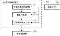
- Itis a block diagram of one embodiment showing the configuration of a three-dimensional image processing unit.
- 4is a flow chart of one embodiment representing the operation of an ultrasound diagnostic apparatus when generating a two-dimensional ultrasound image.
- 4is a flow chart of one embodiment representing the operation of an ultrasound diagnostic apparatus when generating a three-dimensional ultrasound image.
- FIG. 4is a conceptual diagram of one embodiment showing how the scan plane is angularly shifted;
- FIG. 4is a conceptual diagram of one embodiment showing how the scan plane is shifted.
- FIG. 11is a block diagram of another embodiment showing the configuration of a 3D image processing unit;
- FIG. 2is a conceptual diagram of one embodiment depicting an ultrasound probe without motion and with motion;
- FIG. 11is a block diagram of another embodiment showing the configuration of a 3D image processing unit;
- FIG. 4is a conceptual diagram of an embodiment showing how a threshold value is lowered when calculating similarity between frames of two-dimensional ultrasound images in which a heart exists.
- FIG. 4is a block diagram of another embodiment showing the configuration of the ultrasonic diagnostic apparatus of the present invention;
- FIG. 11is a graph of one embodiment of a conversion table representing scores for similarities;
- FIG. 11is a graph of an embodiment of a conversion table representing scores for movement amount detection signals by a motion sensor;
- FIG. 11is a graph of one embodiment of a conversion table representing scores for angle detection signals from a motion sensor;
- FIG. 4is a conceptual diagram of one embodiment showing how the ultrasound probe is rotated;
- FIG. 1is a block diagram of one embodiment showing the configuration of the ultrasonic diagnostic apparatus of the present invention.
- the ultrasonic diagnostic apparatus shown in FIG. 1is a stationary ultrasonic diagnostic apparatus, and includes an ultrasonic probe 1 and an apparatus body 3 connected to the ultrasonic probe 1 .
- the ultrasonic probe 1scans the inspection location of the subject with an ultrasonic beam and outputs sound ray signals corresponding to the two-dimensional ultrasonic image of this inspection location.
- the ultrasonic probe 1includes a transducer array 11 and a transmission/reception circuit 14, as shown in FIG.
- the transducer array 11 and the transmission/reception circuit 14are bidirectionally connected. Further, the transmission/reception circuit 14 is connected to a device control section 36 of the device main body 3, which will be described later.
- the transducer array 11has a plurality of ultrasonic transducers arranged one-dimensionally or two-dimensionally. These transducers transmit ultrasonic waves in accordance with drive signals supplied from the transmitting/receiving circuit 14, receive reflected waves from the subject, and output analog reception signals.
- Each vibratorincludes, for example, a piezoelectric ceramic typified by PZT (Lead Zirconate Titanate), a polymeric piezoelectric element typified by PVDF (Poly Vinylidene Di Fluoride), and PMN-PT ( Lead Magnesium Niobate-Lead Titanate: A piezoelectric single crystal represented by lead magnesium niobate-lead titanate solid solution).
- the transmission/reception circuit 14causes the transducer array 11 to transmit ultrasonic waves, and performs reception focusing processing on reception signals output from the transducer array 11 that have received ultrasonic echoes. to generate a sound ray signal.
- the transmission/reception circuit 14includes a pulser 51 connected to the transducer array 11, an amplifier 52 connected in series from the transducer array 11, an AD (Analog Digital) converter 53, and a beamformer 52. 54 and .
- the pulsar 51includes, for example, a plurality of pulse generators, and ultrasonic waves transmitted from a plurality of transducers of the transducer array 11 generate ultrasonic beams based on a transmission delay pattern selected by the device control unit 36. Each drive signal is supplied to a plurality of transducers with the delay amount adjusted so as to form a waveform.
- a pulsed or continuous wave voltageis applied to the electrodes of the transducers of the transducer array 11
- the piezoelectric bodyexpands and contracts, and pulsed or continuous wave ultrasonic waves are generated from the respective transducers.
- an ultrasonic beamis formed from the composite wave of these ultrasonic waves.
- the transmitted ultrasonic beamis reflected by an object such as a part of the subject and propagates toward the transducer array 11 of the ultrasonic probe 1 .
- Each transducer constituting the transducer array 11expands and contracts upon receiving the ultrasonic echo propagating toward the transducer array 11 in this way, generates a reception signal that is an electrical signal, and receives these signals.
- a signalis output to the amplifier 52 .
- the amplification unit 52amplifies the signal input from each transducer that constitutes the transducer array 11 and transmits the amplified signal to the AD conversion unit 53 .
- the AD converter 53converts the analog signal transmitted from the amplifier 52 into digital received data and outputs the received data to the beamformer 54 .
- the beamformer 54adds each delay to each received data converted by the AD converter 53 according to the sound velocity or the distribution of the sound velocity set based on the reception delay pattern selected by the device controller 36. By doing so, so-called reception focus processing is performed. By this reception focusing process, each piece of reception data converted by the AD conversion unit 53 is phased and added, and an acoustic ray signal in which the focus of the ultrasonic echo is narrowed down is generated.
- the device main body 3generates a two-dimensional ultrasonic image of the inspection location of the subject based on the sound ray signal generated by the ultrasonic probe 1. Furthermore, the apparatus main body 3 generates a three-dimensional ultrasound image of the inspection location of the subject using a plurality of two-dimensional ultrasound images of the inspection location of the subject. The apparatus main body 3 displays two-dimensional ultrasound images and three-dimensional ultrasound images of the examination site of the subject. As shown in FIG. 1, the device main body 3 includes a two-dimensional image generation unit 31, an image memory 32, a three-dimensional image processing unit 35, a display control unit 33, a monitor (display unit) 34, and an input device 37. , and a device control unit 36 .
- a two-dimensional image generation unit 31is connected to the transmission/reception circuit 14, and a display control unit 33 and a monitor 34 are connected to the two-dimensional image generation unit 31 in series.
- An image memory 32is connected to the two-dimensional image generator 31, and a display controller 33 and a three-dimensional image processor 35 are connected to the image memory 32, respectively.
- the display control section 33is connected to the three-dimensional image processing section 35 .
- a device control section 36is connected to the two-dimensional image generation section 31 , the display control section 33 , the image memory 32 and the three-dimensional image processing section 35 , and an input device 37 is connected to the device control section 36 .
- the two-dimensional image generation unit 31uses the transducer array 11 of the ultrasonic probe 1 in a state in which the ultrasonic probe 1 is in contact with the inspection site of the object.
- a two-dimensional ultrasonic image of the inspection location of the subjectis obtained from the received signal obtained by transmitting and receiving the ultrasonic beam to and from the inspection location, more specifically, from the acoustic ray signal generated from the received signal by the transmission and reception circuit 14 (two-dimensional ultrasound image signal).
- the two-dimensional image generating unit 31generates the transducer in a state in which the ultrasonic probe 1 is in contact with and fixed to the examination site of the subject, that is, in a stationary state without movement.
- a plurality of two-dimensional ultrasonic waves with different scanning plane angles or positionsare obtained from received signals obtained by sequentially transmitting and receiving ultrasonic beams while shifting the angle or position of the scanning plane in the elevation direction using the array 11.
- the plurality of two-dimensional ultrasonic imagesare regarded as one set, and one three-dimensional ultrasonic image (three-dimensional ultrasonic image signal) is generated using one set of two-dimensional ultrasonic images.
- the angle of the scanning planemeans the inclination of the scanning plane with respect to the vertical direction.
- shifting the angle of the scanning plane in the elevation directionmeans increasing the inclination of the scanning plane with respect to the vertical direction in the elevation direction.
- the two-dimensional image generator 31has a configuration in which a signal processor 16, a DSC (Digital Scan Converter) 18, and an image processor 17 are connected in series.
- the signal processing unit 16generates image information data corresponding to a two-dimensional ultrasound image based on the acoustic ray signal generated by the transmission/reception circuit 14 . More specifically, the signal processing unit 16 performs signal processing on the sound ray signal generated by the beamformer 54 of the transmission/reception circuit 14, and then, for example, propagates the ultrasonic wave according to the depth of the reflected position. After performing attenuation due to distance correction, envelope detection processing is performed to generate image information data representing tomographic image information regarding tissue within the subject.
- the DSC 18raster-converts the image information data generated by the signal processing unit 16 into an image signal that conforms to the normal television signal scanning method.
- the image processing unit 17performs various corrections such as brightness correction, gradation correction, sharpness correction, image size correction, refresh rate correction, scanning frequency correction, and color correction on the image signal input from the DSC 18 according to the display format of the monitor 34 .
- a two-dimensional ultrasound imageis generated by performing the image processing of , and the image-processed two-dimensional ultrasound image is output to the image memory 32 and the display control unit 33 .
- the image memory 32is a memory that holds a series of two-dimensional ultrasound images of a plurality of frames generated for each examination by the two-dimensional image generation unit 31 under the control of the apparatus control unit 36 .
- the two-dimensional image generation unit 31generates a plurality of two-dimensional ultrasound images with different angles or positions of the scanning planes.
- a dimensional ultrasound imageis held in the image memory 32 .
- the image memory 32includes flash memory, HDD (Hard Disk Drive), SSD (Solid State Drive), FD (Flexible Disc), MO disc (Magneto-Optical disc).
- a recording mediumsuch as a digital card), a USB memory (Universal Serial Bus memory), or an external server can be used.
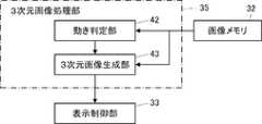
- the three-dimensional image processing unit 35generates a three-dimensional ultrasound image of the inspection site of the subject using a plurality of two-dimensional ultrasound images held in the image memory 32 under the control of the device control unit 36. perform various processing for
- the three-dimensional image processing unit 35has a motion determination unit 42 and a three-dimensional image generation unit 43, as shown in FIG.
- the motion determination section 42 and the three-dimensional image generation section 43are each connected to the image memory 32 .
- a three-dimensional image generation unit 43is connected to the motion determination unit 42
- a display control unit 33is connected to the three-dimensional image generation unit 43 .
- the motion determination unit 42sequentially calculates the degree of similarity between at least two two-dimensional ultrasonic images among the plurality of two-dimensional ultrasonic images held in the image memory 32, and according to this degree of similarity, the ultrasonic probe 1 is within a predetermined reference value.
- a similarity calculation method and a motion determination methodare not particularly limited, and conventionally known various methods can be used.
- the motion determination unit 42calculates, for example, a similarity score and a motion score, and determines whether the motion of the ultrasonic probe 1 is within a reference value depending on whether the similarity is equal to or greater than a predetermined threshold value. It is determined whether or not.
- the movement determination unit 42determines that the movement of the ultrasonic probe 1 is within the reference value, that is, the user of the ultrasonic diagnostic apparatus ( It is determined that the ultrasonic probe 1 is not moved by the examiner).
- the motion determination unit 42calculates, for example, a similarity score between adjacent frames of the two-dimensional ultrasound images for a set of two-dimensional ultrasound images for generating one three-dimensional ultrasound image. Calculate each.
- the two-dimensional ultrasonic imagesAs in the ultrasonic diagnostic apparatus of the present embodiment, when transmitting and receiving ultrasonic beams while shifting the angle or position of the scanning plane in the elevation direction to generate a plurality of two-dimensional ultrasonic images, the two-dimensional ultrasonic images The similarity between adjacent frames of is high, and the scores are always the same. However, if the user moves the ultrasonic probe 1, it is expected that the similarity will drop significantly. Therefore, it is possible to accurately determine whether or not the ultrasonic probe 1 has been moved by the user by observing the change in the degree of similarity.
- ultrasonic beamsare transmitted and received only in the vertical direction to sequentially generate two-dimensional ultrasonic images, and between frames of the two-dimensional ultrasonic images motion detection.
- the ultrasonic probe 1 of the present embodimentsequentially transmits and receives ultrasonic beams while shifting the angle or position of the scanning plane in the elevation direction. Therefore, the time interval between frames of two-dimensional ultrasound images with the same angle or position of the scanning plane, for example, two-dimensional ultrasound images with the scanning plane in the vertical direction, is long. The method of calculating the degree of similarity between frames of two-dimensional ultrasound images of directions cannot accurately detect motion.
- the three-dimensional image generation unit 43selects two-dimensional ultrasound images for which the motion determination unit 42 determines that the motion of the ultrasound probe 1 is within a reference value, among the plurality of two-dimensional ultrasound images held in the image memory 32.
- the imagesare extracted to generate a three-dimensional ultrasound image.
- a method for generating a three-dimensional ultrasonic imageis not particularly limited, and various conventionally known methods for generating a three-dimensional ultrasonic image from two or more two-dimensional ultrasonic images can be used.
- the display control unit 33causes the monitor 34 to display various information under the control of the device control unit 36 .
- the display control unit 33performs predetermined processing on the two-dimensional ultrasound image generated by the two-dimensional image generation unit 31 or the two-dimensional ultrasound image held in the image memory 32, and displays the image after processing.
- a two-dimensional ultrasound imageis displayed on the monitor 34 .
- the display control unit 33also performs predetermined processing on the three-dimensional ultrasound image generated by the three-dimensional image generation unit 43 and causes the monitor 34 to display the processed three-dimensional ultrasound image.
- the monitor 34displays various information under the control of the display control unit 33.
- the monitor 34displays, for example, the two-dimensional ultrasound image generated by the two-dimensional image generation unit 31 or the two-dimensional ultrasound image held in the image memory 32 and the three-dimensional image generated by the three-dimensional image generation unit 43. Displays ultrasound images, etc.
- Examples of the monitor 34include an LCD (Liquid Crystal Display) and an organic EL (Electro-Luminescence) display.
- the input device 37receives various instructions input by the user.
- the input device 37includes, but is not particularly limited to, various buttons, a touch panel, and the like through which the user performs touch operations to input various instructions.
- the device control section 36controls each section of the ultrasonic probe 1 and the device main body 3 based on a program stored in advance and user's instructions input from the input device 37 .
- the two-dimensional image generation unit 31, the three-dimensional image processing unit 35, the display control unit 33, and the device control unit 36are configured by the processor 39.
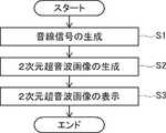
- the transmission/reception circuit 14When generating a two-dimensional ultrasonic image, first, under the control of the device control unit 36, the transmission/reception circuit 14 starts transmitting ultrasonic waves while the ultrasonic probe 1 is in contact with the inspection site of the subject. and a sound ray signal is generated (step S1).
- ultrasonic beamsare transmitted from the plurality of transducers of the transducer array 11 to the inspected portion of the subject according to the drive signal from the pulser 51 .
- An ultrasonic echo from an inspection location based on an ultrasonic beam transmitted from the pulsar 51is received by each transducer of the transducer array 11, and each transducer of the transducer array 11 that has received the ultrasonic echo outputs an analog signal.
- a received signalis output.
- a received signal output from each transducer of the transducer array 11is amplified by the amplifier 52 and AD-converted by the AD converter 53 to obtain received data.
- a sound ray signalis generated by subjecting the received data to reception focusing processing by the beamformer 54 .
- the two-dimensional image generation unit 31generates a two-dimensional ultrasound image of the examination location of the subject based on the acoustic ray signal generated by the beamformer 54 of the transmission/reception circuit 14. is generated (step S2).
- the sound ray signal generated by the beamformer 54is subjected to various signal processings by the signal processing unit 16 to generate image information data representing tomographic image information regarding tissues in the subject.
- the image information data generated by the signal processing unit 16is raster-converted by the DSC 18 and further subjected to various image processing by the image processing unit 17 to generate a two-dimensional ultrasonic image.
- a two-dimensional ultrasound image generated by the image processing unit 17is held in the image memory 32 .
- the display control unit 33performs predetermined processing on the two-dimensional ultrasound image generated by the image processing unit 17 or the two-dimensional ultrasound image held in the image memory 32. It is processed and displayed on the monitor 34 (step S3).
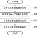
- the ultrasonic probe 1When generating a three-dimensional ultrasonic image, first, under the control of the apparatus control unit 36, the ultrasonic probe 1 is fixed in contact with the inspection site of the subject by the two-dimensional image generation unit 31. A plurality of two-dimensional ultrasonic images with different scanning plane angles or positions are generated from received signals obtained by sequentially transmitting and receiving ultrasonic beams while shifting the angle or position of the scanning plane using the transducer array 11. generated (step S11).
- the one-dimensional transducer array 11when the angle of the scanning plane is shifted using the one-dimensional transducer array 11, inside the housing of the ultrasonic probe 1, the one-dimensional transducer array 11 is rotated by a predetermined angle around the rotation axis.
- the ultrasonic beamsare sequentially transmitted and received while the angle of the scanning surface is sequentially shifted in the elevation direction (see FIG. 2 of Patent Document 3, for example).
- FIG. 2 of Patent Document 3for example.
- the one-dimensional transducer array 11When the position of the scanning plane is shifted using the one-dimensional transducer array 11, the one-dimensional transducer array 11 is mechanically parallel to the elevation direction by a predetermined distance inside the housing of the ultrasonic probe 1. Transmission and reception of ultrasonic beams are sequentially performed while the position of the scanning plane is shifted in the elevation direction (for example, see FIG. 7B). As a result, a plurality of two-dimensional ultrasound images with different scanning plane positions are generated.
- the data of the transducer group extending in the azimuth direction of the two-dimensional transducer array 11are each delayed in the elevation direction, and are each delayed by a predetermined angle.
- the scanning planeis sequentially steered, and the transmission and reception of ultrasonic beams are sequentially performed while the angle of the scanning plane is sequentially shifted in the elevation direction (see, for example, FIG. 7A).
- a plurality of two-dimensional ultrasound images with different scanning plane anglesare generated.
- the transducer group extending in the azimuth direction of the two-dimensional transducer array 11is sequentially selected in the elevation direction, and the position of the scanning plane is shifted in the elevation direction. Transmission and reception of the ultrasonic beams are sequentially performed while shifting the position to . As a result, a plurality of two-dimensional ultrasound images with different scanning plane positions are generated.
- the method of shifting the angle or position of the scanning planeis not limited to the above specific example, and the angle or position of the scanning plane is shifted while the ultrasonic probe 1 is in contact with and fixed to the inspection location of the subject.
- Various methodsare available for
- the two-dimensional ultrasound images generated by the two-dimensional image generation unit 31are sequentially held in the image memory 32 under the control of the device control unit 36.
- the image memory 32holds a plurality of two-dimensional ultrasound images with different scanning plane angles or positions.
- the motion determination unit 42sequentially calculates the similarity between at least two two-dimensional ultrasound images out of the plurality of two-dimensional ultrasound images, and the motion of the ultrasound probe 1 is adjusted to the reference value according to the similarity. Whether or not it is within the range is sequentially determined (step S12). Then, the three-dimensional image generation unit 43 extracts the two-dimensional ultrasound images for which the motion determination unit 42 determines that the motion of the ultrasound probe 1 is within the reference value from among the plurality of two-dimensional ultrasound images. A dimensional ultrasound image is generated (step S13).
- the display control unit 33performs predetermined processing on the three-dimensional ultrasound image generated by the three-dimensional image generation unit 43 under the control of the device control unit 36, and the three-dimensional image after the processing is processed.
- An ultrasonic image(still image) is displayed on the monitor 34 (step S14).
- a plurality of two-dimensional ultrasound images with different angles or positions of the scanning planesare set as one set, and the next set of two-dimensional ultrasound images is generated, and the next set of two-dimensional ultrasound images is generated.
- the next three-dimensional ultrasound imageis generated using the acoustic image, and the next three-dimensional ultrasound image is displayed on the monitor 34, which is sequentially repeated. As a result, the moving image of the three-dimensional ultrasound image is displayed on the monitor 34 .
- the degree of similarity between frames of two-dimensional ultrasonic imagesis calculated, and whether or not the movement of the ultrasonic probe 1 is within a reference value is determined according to the degree of similarity. Then, the two-dimensional ultrasonic image for which the motion of the ultrasonic probe 1 is determined to be within the reference value is extracted to generate the three-dimensional ultrasonic image. As a result, even when the ultrasonic probe 1 is moved by the user, an accurate 3-dimensional ultrasonic image is extracted by extracting a 2-dimensional ultrasonic image for which the movement of the ultrasonic probe 1 is determined to be within the reference value. can be generated.
- the three-dimensional image generation unit 43generates the current three-dimensional ultrasound image when it is determined that the movement of the ultrasound probe 1 exceeds the reference value in the current set of a plurality of two-dimensional ultrasound images. You can choose not to.
- the display control unit 33displays the past 3D ultrasound image immediately before the current 3D ultrasound image on the monitor 34. may be displayed in In this case, the display of the 3D ultrasound image is not updated, but the 3D ultrasound image can be displayed without interruption.
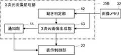
- a notification unit 44is provided in the three-dimensional image processing unit 35B, and when the current three-dimensional ultrasound image is not generated, the notification unit 44 notifies the user of the three-dimensional ultrasound image. The user may be notified with a message indicating that the display was not updated.
- the notification unit 44is connected to the three-dimensional image generation unit 43
- the display control unit 33is connected to the notification unit 44 .
- the display control unit 33When the previous past three-dimensional ultrasound image is displayed on the monitor 34, the display control unit 33, under the control of the notification unit, outputs an accurate three-dimensional ultrasound image due to the movement of the probe by the user.
- the monitor 34may display a message such as "Sound wave image may not be displayed.” This allows the user to know that an accurate three-dimensional ultrasound image may not be displayed.
- the method of notifying the user of the messagemay be, as described above, by displaying the message on the monitor 34 under the control of the notification unit, or by outputting a voice reading the message from a speaker (not shown). or both at the same time.
- the three-dimensional image generator 43when it is determined that the motion of the ultrasonic probe 1 exceeds the reference value, the three-dimensional image generator 43 generates a plurality of two-dimensional ultrasonic images generated by a plurality of scanning planes as shown in FIG.
- a partial three-dimensional ultrasound imagemay be generated by extracting the two-dimensional ultrasound image determined to have no motion up to the time point when it was determined to have motion.
- the two-dimensional ultrasonic image before it is determined that the motion of the ultrasonic probe 1 exceeds the reference valuethat is, the two-dimensional ultrasonic image in which the motion of the ultrasonic probe 1 is determined to be within the reference value.
- the display control unit 33causes the monitor 34 to display this partial three-dimensional ultrasound image.
- the 3D ultrasound imagecan be displayed without interruption, although it is not a complete 3D ultrasound image.
- the method of determining the degree of similarityin other words, the method of determining the movement of the ultrasonic probe 1 may be changed according to the object to be observed in the two-dimensional ultrasonic image, for example, organs such as the heart and blood vessels. good.
- an observation object identification unit 41is provided in the three-dimensional image processing unit 35C. , the object to be observed present in each of the plurality of two-dimensional ultrasound images is specified.
- an observation object identification unit 41is connected to the image memory 32 , and a motion determination unit 42 is connected to the observation object identification unit 41 .
- the method of identifying the observation objectis not particularly limited, but conventionally identifying the observation object from a two-dimensional ultrasound image, such as a method using a judgment model generated by machine learning, a method using template matching, etc. Various known methods can be used.
- the motion determination unit 42may change the similarity threshold according to the observation target identified by the observation target identification unit. For example, if at least two two-dimensional ultrasound images used for calculating the degree of similarity include two-dimensional ultrasound images in which predetermined observation targets such as the heart and blood vessels are present, the motion determination unit 42 determines that the similarity Change the degree threshold.
- the heartwhen the heart is visualized using an ultrasonic diagnostic apparatus, even if the ultrasonic probe 1 is not moved by the user, there is a possibility that the similarity between the frames of the two-dimensional ultrasonic image will decrease due to the heartbeat.
- the heart present in each of a plurality of two-dimensional ultrasound imagesis specified, and at least two two-dimensional ultrasound images used for similarity calculation are identified as having a heart. If a two-dimensional ultrasound image is included, the threshold for calculating the degree of similarity is lowered. As a result, the degree of similarity can be calculated in consideration of the influence of heart beat.
- the similarity between frames of two-dimensional ultrasonic imagesis low even when the ultrasonic probe 1 is not moved by the user.
- a kidneyis identified from the two-dimensional ultrasound image, and the threshold value for calculating the degree of similarity is lowered when the kidney is present.
- two-dimensional ultrasoundthat changes the similarity threshold for frames of two-dimensional ultrasound images in which the heart exists is used. You may expand the extent of the frame of the image. That is, when at least two two-dimensional ultrasound images used for calculating the degree of similarity include two-dimensional ultrasound images in which the determined observation target exists, the motion determination unit 42 determines that the determined observation target
- the similarity thresholdmay be changed for a two-dimensional ultrasound image in which there is a , and two-dimensional ultrasound images for a predetermined number of frames before and after it.
- the observation target identification unit 41determines that a predetermined observation target exists, for example, the observation target and five frames of two-dimensional ultrasound images before and after the observation target are identified as similar images. Change the degree threshold.
- a predetermined observation targetexists
- the observation target and five frames of two-dimensional ultrasound images before and after the observation targetare identified as similar images.
- Change the degree thresholdAs shown in FIG. 7B, when ultrasonic beams are transmitted and received while the position of the scanning plane is shifted in the elevation direction using the transducer array 11, for example, the number of frames corresponding to 1 cm before and after the observation target is Lower the similarity threshold for two-dimensional ultrasound images.
- FIG. 9when transmitting and receiving ultrasonic beams while shifting the angle of the scanning plane using the transducer array 11, for example, two-dimensional ultrasonic images for 10° before and after the observation object , lower the similarity threshold.
- the amount of change in angle or position of adjacent scanning planesis set as a parameter for generating a plurality of two-dimensional ultrasonic images used to generate a three-dimensional ultrasonic image. . Therefore, the motion determination unit 42 acquires this parameter, and when changing the similarity threshold, can calculate the angle or distance in front of and behind the observed object based on this parameter.
- the similarity thresholdwhen depicting blood vessels using an ultrasonic diagnostic apparatus, the similarity threshold may be changed according to the direction in which the blood vessels are depicted.
- the two-dimensional ultrasound imagewhen the short-axis image of the blood vessel is to be rendered, the two-dimensional ultrasound image changes little between frames, so the similarity threshold is not changed. Since the two-dimensional ultrasound image changes at , the similarity threshold is lowered.
- the similarity thresholdmay be changed according to the area of the observation object with respect to the area of the entire two-dimensional ultrasound image. For example, if the area of the observation target with respect to the area of the entire two-dimensional ultrasound image is equal to or less than a predetermined threshold, the similarity threshold is lowered.
- the motion determination unit 42can change the threshold according to at least one of the type of observation object such as the heart and blood vessels, the rendering direction of the observation object, and the area of the observation object. desirable.
- the motion determination unit 42may determine the past of the two-dimensional ultrasound image by a predetermined number of frames, for example, 20 frames in the past, or the number of frames in the past 1 second calculated from the frame rate. store the similarity of Furthermore, based on the past similarities, the motion determination unit 42 obtains, for example, the average value or the median value of the past similarities, or the number of the past similarities from the top as the similarity reference value. , compare the similarity reference value with the current similarity. Here, it may be determined that the ultrasonic probe 1 has moved when the current similarity with respect to the similarity reference value is below a predetermined threshold value. Specifically, the case where the similarity reference value and the current similarity are completely matched is set to 100%.
- the movement determination unit 42may determine that the movement of the ultrasonic probe 1 exceeds the reference value, that is, that the ultrasonic probe 1 has moved. In other words, it may be determined that the ultrasonic probe 1 has moved when the current similarity is out of the range of the defined threshold compared with the similarity reference value.
- the motion determination unit 42stores the similarity reference value at the timing when it is determined that the ultrasonic probe 1 has moved, as the similarity in the stationary state. Furthermore, the motion determination unit 42 determines that the motion of the ultrasonic probe 1 is within the reference value, that is, the period during which the ultrasonic probe 1 is determined to have no motion. It may be determined that the ultrasonic probe 1 is stationary again when the current degree of similarity with respect to the degree reference value falls within a predetermined threshold value. Specifically, when the similarity in the previously saved static state and the current similarity are 100%, and the current similarity is compared to the similarity in the static state, for example , 80%, it may be determined that the ultrasonic probe 1 has stopped again.
- the current similarityis compared with the similarity reference value (similarity in the stationary state) saved at that timing. , it may be determined that the ultrasonic probe 1 has stopped again when it is within the range of the defined threshold value.
- the motion determination unit 42generates the amount of change in the angle or position of the scanning plane, or the temporal acquisition interval of each frame of a plurality of two-dimensional ultrasound images, in other words, a plurality of two-dimensional ultrasound images.
- the frame interval between at least two two-dimensional ultrasound images used to calculate the degree of similaritymay be changed according to the frame rate at the time of calculation. That is, as the frame rate increases, the frame interval is changed to be longer.
- the steering angleis shifted in 31 steps from +15 degrees to -15 degrees in increments of 1 degree
- the steering angleis shifted in 0.5 degree increments. It is assumed that parameters are set so as to shift in 61 steps from +15 degrees to -15 degrees.
- the amount of change in angle or position of the scan planeis very small. Therefore, in the case of the second mode, instead of calculating the degree of similarity between consecutive frames, intermediate frames may be thinned out from a plurality of consecutive frames, and the degree of similarity may be calculated using the remaining frames.
- the similarity between the two-dimensional ultrasound images of n/n+1 framesis calculated, then the similarity between the two-dimensional ultrasound images of n+1/n+2 frames is calculated, and so on.
- the similarity between two-dimensional ultrasound images of n/n+3 framesis calculated, the similarity between two-dimensional ultrasound images of n+4/n+7 frames is calculated, and so on.
- intermediate framesare thinned out from a plurality of consecutive frames, and the similarity is calculated using the remaining two frames.
- the motion determination unit 42may calculate the similarity while thinning out a predetermined number of frames of the two-dimensional ultrasound images at predetermined frame intervals from the plurality of two-dimensional ultrasound images. For example, the similarity between the two-dimensional ultrasound images of the n/n+1 frames is calculated, the two-dimensional ultrasound images of the n+2th frame are skipped, and the similarity between the two-dimensional ultrasound images of the n+3/n+4 frames is calculated.
- the degreeis calculated, the two-dimensional ultrasonic image of the n+5th frame is skipped, the similarity of the two-dimensional ultrasonic image of the n+6/n+7th frame is calculated, and so on, a plurality of two-dimensional ultrasonic waves
- the similarityis calculated while thinning out some frames of the image. This makes it possible to reduce the calculation load more than when calculating the similarity between two-dimensional ultrasound images between all frames.
- the motion of the ultrasonic probe 1may be detected using a motion sensor.
- the motion sensor 15detects the motion of the ultrasonic probe 1 under the control of the device control unit 36 and outputs the detection signal, and is attached to the ultrasonic probe 1.
- the motion sensor 15is connected to the device controller 36 of the device main body 3 .
- the detection signal of the motion sensor 15includes a detection signal of the position (movement amount) in the movement direction such as parallel movement of the ultrasonic probe 1 along the epidermis of the subject, and a detection signal of the tilt angle of the ultrasonic probe 1. detection signals, etc.
- the motion determination unit 42determines whether or not the motion of the ultrasonic probe 1 is within a reference value based on the degree of similarity and the detection signal of the motion of the ultrasonic probe 1 output from the motion sensor 15. .
- a motion detection methodis not particularly limited, and various conventionally known methods can be used.
- the movement of the ultrasonic probe 1includes changes in the position (amount of movement) of the ultrasonic probe 1 in the movement direction, changes in the angle of the ultrasonic probe 1, and the like.
- an acceleration sensoras the motion sensor 15
- FIG.On the other hand, it is difficult to detect a change in the position of the ultrasonic probe 1 in the moving direction using an acceleration sensor.
- a magnetic sensoris used as the motion sensor 15, and in the three-dimensional space of the magnetic field generated by the magnetic field generator, a magnetic field position detector based on the position detection signal and the angle detection signal output from the magnetic sensor,
- the magnetic sensorthat is, can detect the position of the ultrasonic probe 1 in the moving direction and the angle of the ultrasonic probe 1 with respect to the vertical direction (inclination of the ultrasonic probe 1 with respect to the vertical direction).
- the motion determination unit 42may determine the motion of the ultrasonic probe 1 based only on the degree of similarity, or may determine the motion of the ultrasonic probe 1 based only on the detection signal of the motion sensor. Both may be used to determine the motion of the ultrasound probe 1 .
- the motion determination unit 42can score the similarity and the detection signal of the motion sensor, and determine the presence or absence of motion of the ultrasonic probe 1 based on the total value.
- FIG. 13Ais a graph of an embodiment of a conversion table representing scores for similarity
- FIG. 13Bis a graph of an embodiment of a conversion table representing scores for detection signals of movement amounts by the motion sensor
- 4is a graph of an embodiment of a conversion table representing scores for angle detection signals by sensor 15.
- FIG. The horizontal axes of the graphs shown in FIGS. 13A, 13B, and 13Crepresent the similarity, the amount of movement, and the angle, respectively, and the vertical axes represent the score corresponding to the degree of similarity, the amount of movement, and the angle.
- the motion determination unit 42uses the conversion tables of the graphs shown in FIGS. A score is calculated for the detected signal, and these three scores are summed to obtain a final total score.
- the movement determination unit 42compares the total score with a predetermined threshold, and determines that the ultrasonic probe is moving when the total score is equal to or greater than the threshold. If it is less than the threshold, it is determined that the ultrasonic probe 1 is not moving.
- the conversion table graphs shown in FIGS. 13A, 13B, and 13Care examples.
- the upper limit of the score of each conversion tableis 1.0, but it can be set to any value.
- weightingmay be performed by setting the upper limit of the score of the similarity conversion table higher than the upper limit of the score of the other conversion tables.
- the shape of each graphis not limited to the shape of the graphs shown in FIGS. 13A, 13B and 13C.
- the presence or absence of motion of the ultrasonic probe 1may be determined based on the degree of similarity and the motion sensor 15, respectively, and the motion of the ultrasonic probe 1 may be finally determined based on a combination of these determination results.
- the final determination result when the motion of the ultrasonic probe 1 is determined by the AND condition of the determination result based on the similarity and the determination result by the motion sensor 15is as follows. a. Similarity: no motion, motion sensor: no motion ⁇ final determination result: no motion b. Similarity: motion, motion sensor: no motion ⁇ final determination result: no motion c. Similarity: no motion, motion sensor: motion -> final determination result: no motion d. Similarity: movement, motion sensor: movement ⁇ final judgment result: movement
- the final judgment resultis different from the judgment result based on the similarity alone.
- the motion determination unit 42uses the determination result of the motion sensor 15 to determine the motion of the ultrasonic probe 1, so that when the ultrasonic probe 1 is in a stationary state, it is correctly determined that there is no motion. will be able to
- the final determination result when the motion of the ultrasonic probe 1 is determined by the OR condition of the determination result based on the similarity and the determination result by the motion sensor 15is as follows. a. Similarity: no motion, motion sensor: no motion ⁇ final determination result: no motion b. Similarity: motion, motion sensor: no motion ⁇ final determination result: motion c. Similarity: no motion, motion sensor: motion -> final determination result: motion d. Similarity: movement, motion sensor: movement ⁇ final judgment result: movement
- the final judgment resultis different from the judgment result based on the similarity alone.
- the ultrasonic probe 1when the ultrasonic probe 1 is manually rotated by the user at a speed close to the change in angle that causes the transducer array 11 to steer in the elevation direction, the ultrasonic probe 1 is moving. Nevertheless, the angle of the scanning plane does not change much. In this case, the similarity is high even though the ultrasonic probe 1 is moved.
- the motion determination unit 42determines that the final determination result indicates that there is motion, so that the motion of the ultrasonic probe 1 can be correctly determined. can.
- the combination (AND condition, OR condition) of the total value of the similarity and motion sensor score, the similarity determination result, and the motion sensor 15 determination result (AND condition, OR condition)is set in advance for each examination. good too.
- the AND condition of the similarity determination result and the determination result of the motion sensor 15is adopted, and in the case of the bladder, the OR condition of the similarity determination result and the determination result of the motion sensor 15 is adopted. is adopted, and in other cases, the total value of the similarity and the score of the motion sensor 15 is adopted.
- the present inventionis not limited to a stationary ultrasonic diagnostic apparatus, but also a portable ultrasonic diagnostic apparatus in which the device main body 3 is realized by a laptop terminal device, and a smartphone or a tablet PC (Personal The present invention can also be applied to a handheld ultrasonic diagnostic apparatus realized by a handheld terminal device such as a computer (personal computer).
- the ultrasonic probe 1 and the apparatus main body 3may be connected by wire or wirelessly.
- all of the two-dimensional image generation unit 31 or only the signal processing unit 16may be provided on the ultrasonic probe 1 side, or may be provided on the device main body 3 side.
- the hardware of a processing unitthat executes various processes such as the transmission/reception circuit 14, the two-dimensional image generation unit 31, the display control unit 33, the three-dimensional image processing unit 35, and the device control unit 36
- the typical configurationmay be dedicated hardware, or various processors or computers that execute programs.
- the circuit configurationcan be changed after manufacturing such as CPU (Central Processing Unit), FPGA (Field Programmable Gate Array), etc., which are general-purpose processors that run software (programs) and function as various processing units.
- Programmable Logic DevicePLD
- ASICApplication Specific Integrated Circuit
- One processing unitmay be composed of one of these various processors, or a combination of two or more processors of the same or different type, such as a combination of multiple FPGAs, or a combination of FPGAs and CPUs. and so on. Also, the plurality of processing units may be configured by one of various processors, or two or more of the plurality of processing units may be combined into one processor.
- SoCSystem on Chip
- the hardware configuration of these various processorsis, more specifically, an electric circuit that combines circuit elements such as semiconductor elements.
- the method of the present inventioncan be implemented, for example, by a program for causing a computer to execute each step. It is also possible to provide a computer-readable recording medium on which this program is recorded.
Landscapes
- Health & Medical Sciences (AREA)
- Life Sciences & Earth Sciences (AREA)
- Engineering & Computer Science (AREA)
- Heart & Thoracic Surgery (AREA)
- Molecular Biology (AREA)
- Biophysics (AREA)
- Nuclear Medicine, Radiotherapy & Molecular Imaging (AREA)
- Pathology (AREA)
- Radiology & Medical Imaging (AREA)
- Biomedical Technology (AREA)
- Veterinary Medicine (AREA)
- Medical Informatics (AREA)
- Physics & Mathematics (AREA)
- Surgery (AREA)
- Animal Behavior & Ethology (AREA)
- General Health & Medical Sciences (AREA)
- Public Health (AREA)
- Computer Vision & Pattern Recognition (AREA)
- Computer Graphics (AREA)
- General Engineering & Computer Science (AREA)
- Ultra Sonic Daignosis Equipment (AREA)
Abstract
Description
Translated fromJapanese本発明は、2次元超音波画像および3次元超音波画像を生成して表示する機能を有する超音波診断装置および超音波診断装置の制御方法に関する。The present invention relates to an ultrasonic diagnostic apparatus having a function of generating and displaying a two-dimensional ultrasonic image and a three-dimensional ultrasonic image, and a control method for the ultrasonic diagnostic apparatus.
例えば、特許文献1-3には、2次元超音波画像および3次元超音波画像の両方を生成することができる超音波診断装置が記載されている。For example,
3次元超音波画像を生成するためには、例えば、走査面の角度または位置をエレベーション方向へずらしながら超音波ビームの送受信を行って複数の2次元超音波画像を生成し、この複数の2次元超音波画像を用いて3次元超音波画像を生成するというように、ある程度の幅を持った時間が必要である。そのため、3次元超音波画像を生成するために用いられる複数の2次元超音波画像を生成している間に、ユーザによって超音波プローブが動かされた場合、正確な3次元超音波画像を生成することができない。In order to generate a three-dimensional ultrasonic image, for example, ultrasonic beams are transmitted and received while shifting the angle or position of the scanning plane in the elevation direction to generate a plurality of two-dimensional ultrasonic images. A certain amount of time is required to generate a three-dimensional ultrasound image using a three-dimensional ultrasound image. Therefore, when the ultrasound probe is moved by the user while generating a plurality of two-dimensional ultrasound images used to generate the three-dimensional ultrasound image, an accurate three-dimensional ultrasound image is generated. I can't.
例えば、特許文献1,4には、2次元超音波画像のフレーム間の動きベクトルおよび類似度を算出することにより超音波プローブの動きを判定し、その判定結果に応じた処理を行うことが記載されている。
しかし、特許文献1-4には、超音波画像のフレーム間の動きベクトルまたは類似度の算出結果に基づいて、3次元超音波画像を生成するために用いられる複数の2次元超音波画像のフレームを選択することは記載されていない。For example,
However, in
本発明の目的は、超音波プローブが動かされた場合であっても、正確な3次元超音波画像を生成することができる超音波診断装置および超音波診断装置の制御方法を提供することにある。SUMMARY OF THE INVENTION An object of the present invention is to provide an ultrasonic diagnostic apparatus and a method for controlling the ultrasonic diagnostic apparatus that can generate an accurate three-dimensional ultrasonic image even when the ultrasonic probe is moved. .
上記目的を達成するために、本発明は、振動子アレイを有する超音波プローブと、
超音波プローブが被検体の検査箇所に接触されて固定された状態において、振動子アレイを用いて走査面の角度または位置をずらしながら超音波ビームの送受信を順次行うことにより得られた受信信号から複数の2次元超音波画像を生成する2次元画像生成部と、
複数の2次元超音波画像のうちの少なくとも2つの2次元超音波画像の類似度を順次算出し、類似度に応じて、超音波プローブの動きが、定められた基準値以内であるか否かを順次判定する動き判定部と、
複数の2次元超音波画像のうち、超音波プローブの動きが基準値以内であると判定された2次元超音波画像を抜き出して3次元超音波画像を生成する3次元画像生成部と、
モニタと、
3次元超音波画像をモニタに表示させる表示制御部と、を備える、超音波診断装置を提供する。To achieve the above object, the present invention provides an ultrasonic probe having a transducer array,
From the received signal obtained by sequentially transmitting and receiving ultrasonic beams while shifting the angle or position of the scanning plane using the transducer array while the ultrasonic probe is in contact with and fixed to the inspection site of the subject a two-dimensional image generator that generates a plurality of two-dimensional ultrasound images;
Sequentially calculating the degree of similarity of at least two two-dimensional ultrasonic images out of a plurality of two-dimensional ultrasonic images, and depending on the degree of similarity, whether or not the movement of the ultrasonic probe is within a predetermined reference value a motion determination unit that sequentially determines the
a three-dimensional image generation unit that extracts a two-dimensional ultrasound image for which the movement of the ultrasound probe is determined to be within a reference value from among the plurality of two-dimensional ultrasound images and generates a three-dimensional ultrasound image;
a monitor;
and a display controller for displaying a three-dimensional ultrasound image on a monitor.
ここで、3次元画像生成部は、超音波プローブの動きが基準値を超えたと判定された場合に、現在の3次元超音波画像を生成せず、
表示制御部は、現在の3次元超音波画像が生成されなかった場合に、現在の3次元超音波画像の1つ前の過去の3次元超音波画像をモニタに表示させることが好ましい。Here, the three-dimensional image generation unit does not generate the current three-dimensional ultrasound image when it is determined that the movement of the ultrasound probe exceeds the reference value,
Preferably, the display control unit causes the monitor to display a past three-dimensional ultrasound image immediately before the current three-dimensional ultrasound image when the current three-dimensional ultrasound image has not been generated.
また、現在の3次元超音波画像が生成されなかった場合に、3次元超音波画像の表示が更新されなかったことを表すメッセージをユーザに通知する通知部を備え、
表示制御部は、1つ前の過去の3次元超音波画像をモニタに表示させた場合に、メッセージをモニタに表示させることが好ましい。Further, a notification unit for notifying the user of a message indicating that the display of the 3D ultrasound image has not been updated when the current 3D ultrasound image has not been generated,
Preferably, the display control unit causes the monitor to display the message when the previous past three-dimensional ultrasound image is displayed on the monitor.
また、動き判定部は、類似度が、定められたしきい値以上であった場合に、超音波プローブの動きが基準値以内であると判定することが好ましい。Also, it is preferable that the motion determination unit determines that the motion of the ultrasonic probe is within the reference value when the degree of similarity is equal to or greater than a predetermined threshold value.
また、複数の2次元超音波画像のそれぞれに基づいて、複数の2次元超音波画像のそれぞれに存在する観察対象物を特定する観察対象物特定部を備え、
動き判定部は、観察対象物に応じて、しきい値を変更することが好ましい。Further, an observation target identification unit that identifies an observation target existing in each of the plurality of two-dimensional ultrasonic images based on each of the plurality of two-dimensional ultrasonic images,
It is preferable that the motion determination unit changes the threshold according to the observed object.
また、動き判定部は、少なくとも2つの2次元超音波画像が、定められた観察対象物が存在する2次元超音波画像を含む場合に、しきい値を変更することが好ましい。Also, the motion determination unit preferably changes the threshold value when at least two two-dimensional ultrasound images include two-dimensional ultrasound images in which a defined observation target exists.
また、動き判定部は、少なくとも2つの2次元超音波画像が、定められた観察対象物が存在する2次元超音波画像を含む場合に、定められた観察対象物が存在する2次元超音波画像、および、定められた観察対象物が存在する2次元超音波画像の前後の定められたフレーム数分の2次元超音波画像に対して、しきい値を変更することが好ましい。In addition, the motion determining unit determines the two-dimensional ultrasound image in which the determined observation target exists when at least two two-dimensional ultrasound images include the two-dimensional ultrasound image in which the determined observation target exists. , and a predetermined number of frames before and after the two-dimensional ultrasonic image in which the predetermined observation target exists, the threshold value is preferably changed.
また、動き判定部は、観察対象物の種類、観察対象物の描出方向および観察対象物の面積の少なくとも1つに応じて、しきい値を変更することが好ましい。Also, it is preferable that the motion determination unit changes the threshold according to at least one of the type of observation target, the rendering direction of the observation target, and the area of the observation target.
また、動き判定部は、定められたフレーム数分の2次元超音波画像の類似度に基づいて類似度基準値を求め、類似度基準値に対して現在の類似度が、定められたしきい値を下回った場合に、超音波プローブの動きが基準値を超えたと判定することが好ましい。Further, the motion determination unit obtains a similarity reference value based on the similarity of the two-dimensional ultrasound images for a predetermined number of frames, and the current similarity with respect to the similarity reference value is the predetermined threshold. It is preferable to determine that the movement of the ultrasound probe has exceeded the reference value when the value is below the value.
また、動き判定部は、類似度基準値に対して現在の類似度が、定められたしきい値を下回ったタイミングにおける類似度基準値を保存しておき、超音波プローブの動きが、基準値以内であると判定されている期間において、保存された類似度基準値に対して、現在の類似度が、定められたしきい値以内に収まった場合に、超音波プローブが静止したと判定することが好ましい。Further, the motion determination unit stores the similarity reference value at the timing when the current similarity with respect to the similarity reference value falls below a predetermined threshold, It is determined that the ultrasonic probe is stationary when the current similarity is within a predetermined threshold with respect to the stored similarity reference value in the period determined to be within is preferred.
また、動き判定部は、複数の2次元超音波画像を生成する際のフレームレートに応じて、少なくとも2つの2次元超音波画像のフレーム間隔を変更することが好ましい。Also, the motion determination unit preferably changes the frame interval between at least two two-dimensional ultrasound images according to the frame rate when generating the two-dimensional ultrasound images.
また、動き判定部は、複数の2次元超音波画像から、定められたフレーム間隔で、定められたフレーム数の2次元超音波画像を間引きながら類似度を算出することが好ましい。Further, it is preferable that the motion determination unit calculates the degree of similarity while thinning out a predetermined number of frames of the two-dimensional ultrasound images at predetermined frame intervals from the plurality of two-dimensional ultrasound images.
また、超音波プローブに取り付けられた動きセンサを備え、
動き判定部は、類似度と、動きセンサから出力される超音波プローブの動きの検出信号とに基づいて、超音波プローブの動きが基準値以内であるか否かを判定することが好ましい。It also has a motion sensor attached to the ultrasound probe,
Preferably, the motion determination unit determines whether or not the motion of the ultrasonic probe is within a reference value based on the degree of similarity and the detection signal of the motion of the ultrasonic probe output from the motion sensor.
また、本発明は、2次元画像生成部が、振動子アレイを有する超音波プローブが被検体の検査箇所に接触されて固定された状態において、振動子アレイを用いて走査面の角度または位置をずらしながら超音波ビームの送受信を順次行うことにより得られた受信信号から複数の2次元超音波画像を生成するステップと、
動き判定部が、複数の2次元超音波画像のうちの少なくとも2つの2次元超音波画像の類似度を順次算出し、類似度に応じて、超音波プローブの動きが、定められた基準値以内であるか否かを順次判定するステップと、
3次元画像生成部が、複数の2次元超音波画像のうち、超音波プローブの動きが基準値以内であると判定された2次元超音波画像を抜き出して3次元超音波画像を生成するステップと、
表示制御部が、3次元超音波画像をモニタに表示させるステップと、を含む、超音波診断装置の制御方法を提供する。Further, in the present invention, the two-dimensional image generating unit uses the transducer array to determine the angle or position of the scanning plane in a state in which the ultrasonic probe having the transducer array is in contact with and fixed to the inspection site of the subject. generating a plurality of two-dimensional ultrasound images from received signals obtained by sequentially transmitting and receiving ultrasound beams while shifting;
A motion determination unit sequentially calculates a similarity between at least two two-dimensional ultrasound images out of a plurality of two-dimensional ultrasound images, and according to the similarity, the motion of the ultrasound probe is within a predetermined reference value. a step of sequentially determining whether or not
a step in which the three-dimensional image generating unit extracts a two-dimensional ultrasonic image in which the movement of the ultrasonic probe is determined to be within a reference value from among the plurality of two-dimensional ultrasonic images to generate a three-dimensional ultrasonic image; ,
A display control unit displaying a three-dimensional ultrasound image on a monitor.
本発明においては、2次元超音波画像のフレーム間の類似度を算出し、この類似度に応じて、超音波プローブの動きが基準値以内であるか否かを判定し、超音波プローブの動きが基準値以内であると判定された2次元超音波画像を抜き出して3次元超音波画像が生成される。これにより、本発明によれば、ユーザによって超音波プローブが動かされた場合であっても、超音波プローブの動きが基準値以内であると判定された2次元超音波画像を抜き出して正確な3次元超音波画像を生成することができる。In the present invention, the degree of similarity between frames of two-dimensional ultrasound images is calculated. A two-dimensional ultrasound image determined to be within the reference value is extracted to generate a three-dimensional ultrasound image. As a result, according to the present invention, even when the user moves the ultrasonic probe, the two-dimensional ultrasonic image for which the movement of the ultrasonic probe is determined to be within the reference value is extracted and an accurate three-dimensional image is extracted. A dimensional ultrasound image can be generated.
以下に、添付の図面に示す好適実施形態に基づいて、本発明の超音波診断装置および超音波診断装置の制御方法を詳細に説明する。The ultrasonic diagnostic apparatus and control method for the ultrasonic diagnostic apparatus of the present invention will be described in detail below based on preferred embodiments shown in the accompanying drawings.
図1は、本発明の超音波診断装置の構成を表す一実施形態のブロック図である。図1に示す超音波診断装置は、据置型の超音波診断装置であって、超音波プローブ1と、この超音波プローブ1と接続される装置本体3と、を備えている。FIG. 1 is a block diagram of one embodiment showing the configuration of the ultrasonic diagnostic apparatus of the present invention. The ultrasonic diagnostic apparatus shown in FIG. 1 is a stationary ultrasonic diagnostic apparatus, and includes an
超音波プローブ1は、超音波ビームにより被検体の検査箇所をスキャンして、この検査箇所の2次元超音波画像に対応する音線信号を出力する。超音波プローブ1は、図1に示すように、振動子アレイ11と、送受信回路14と、を備えている。振動子アレイ11と送受信回路14とは双方向に接続されている。また、送受信回路14には、後述する装置本体3の装置制御部36が接続されている。The
振動子アレイ11は、1次元または2次元に配列された複数の超音波振動子を有している。これらの振動子は、それぞれ送受信回路14から供給される駆動信号に従って超音波を送信し、かつ、被検体からの反射波を受信してアナログの受信信号を出力する。
各振動子は、例えば、PZT(Lead Zirconate Titanate:チタン酸ジルコン酸鉛)に代表される圧電セラミック、PVDF(Poly Vinylidene Di Fluoride:ポリフッ化ビニリデン)に代表される高分子圧電素子およびPMN-PT(Lead Magnesium Niobate-Lead Titanate:マグネシウムニオブ酸鉛-チタン酸鉛固溶体)に代表される圧電単結晶等からなる圧電体の両端に電極を形成した素子を用いて構成される。The
Each vibrator includes, for example, a piezoelectric ceramic typified by PZT (Lead Zirconate Titanate), a polymeric piezoelectric element typified by PVDF (Poly Vinylidene Di Fluoride), and PMN-PT ( Lead Magnesium Niobate-Lead Titanate: A piezoelectric single crystal represented by lead magnesium niobate-lead titanate solid solution).
送受信回路14は、装置制御部36による制御の下で、振動子アレイ11から超音波を送信させ、かつ、超音波エコーを受信した振動子アレイ11から出力される受信信号に受信フォーカス処理を施すことにより音線信号を生成する。送受信回路14は、図2に示すように、振動子アレイ11に接続されるパルサ51と、振動子アレイ11から順次直列に接続される増幅部52、AD(Analog Digital)変換部53およびビームフォーマ54と、を有している。Under the control of the
パルサ51は、例えば複数のパルス発生器を含んでおり、装置制御部36により選択された送信遅延パターンに基づいて、振動子アレイ11の複数の振動子から送信される超音波が超音波ビームを形成するようにそれぞれの駆動信号を、遅延量を調節して複数の振動子に供給する。このように、振動子アレイ11の振動子の電極にパルス状または連続波状の電圧が印加されると、圧電体が伸縮し、それぞれの振動子からパルス状または連続波状の超音波が発生して、それらの超音波の合成波から、超音波ビームが形成される。The
送信された超音波ビームは、例えば、被検体の部位等の対象において反射され、超音波プローブ1の振動子アレイ11に向かって伝搬する。振動子アレイ11を構成するそれぞれの振動子は、このように振動子アレイ11に向かって伝搬する超音波エコーを受信することにより伸縮して、電気信号である受信信号を発生し、これらの受信信号を増幅部52に出力する。The transmitted ultrasonic beam is reflected by an object such as a part of the subject and propagates toward the
増幅部52は、振動子アレイ11を構成するそれぞれの振動子から入力された信号を増幅し、増幅した信号をAD変換部53に送信する。AD変換部53は、増幅部52から送信されたアナログの信号をデジタルの受信データに変換し、これらの受信データをビームフォーマ54に出力する。The
ビームフォーマ54は、装置制御部36により選択された受信遅延パターンに基づいて設定される音速または音速の分布に従い、AD変換部53により変換された各受信データに対してそれぞれの遅延を与えて加算することにより、いわゆる受信フォーカス処理を行う。この受信フォーカス処理により、AD変換部53で変換された各受信データが整相加算され、かつ、超音波エコーの焦点が絞り込まれた音線信号が生成される。The
次に、装置本体3は、超音波プローブ1によって生成された音線信号に基づいて、被検体の検査箇所の2次元超音波画像を生成する。さらに、装置本体3は、被検体の検査箇所の複数の2次元超音波画像を用いて被検体の検査箇所の3次元超音波画像を生成する。装置本体3は、被検体の検査箇所の2次元超音波画像および3次元超音波画像を表示する。装置本体3は、図1に示すように、2次元画像生成部31と、画像メモリ32と、3次元画像処理部35と、表示制御部33と、モニタ(表示部)34と、入力装置37と、装置制御部36と、を備えている。Next, the device
2次元画像生成部31は送受信回路14に接続され、2次元画像生成部31には、表示制御部33およびモニタ34が順次直列に接続されている。また、2次元画像生成部31には画像メモリ32が接続され、画像メモリ32には、表示制御部33および3次元画像処理部35がそれぞれ接続されている。さらに、3次元画像処理部35には表示制御部33が接続されている。2次元画像生成部31、表示制御部33、画像メモリ32および3次元画像処理部35には装置制御部36が接続され、装置制御部36には入力装置37が接続されている。A two-dimensional
2次元画像生成部31は、装置制御部36の制御の下で、超音波プローブ1が被検体の検査箇所に接触された状態において、超音波プローブ1が有する振動子アレイ11を用いて被検体の検査箇所に超音波ビームの送受信を行うことにより得られた受信信号から、さらに言えば、送受信回路14によって受信信号から生成された音線信号から、被検体の検査箇所の2次元超音波画像(2次元超音波画像信号)を生成する。
また、2次元画像生成部31は、超音波プローブ1が被検体の検査箇所に接触されて固定された状態、すなわち、動いていない静止状態において、図7Aおよび図7Bに示すように、振動子アレイ11を用いて走査面の角度または位置をエレベーション方向へずらしながら超音波ビームの送受信を順次行うことにより得られた受信信号から、それぞれ走査面の角度または位置が異なる複数の2次元超音波画像を生成する。この複数の2次元超音波画像を1組として、1組の複数の2次元超音波画像を用いて1つの3次元超音波画像(3次元超音波画像信号)が生成される。ここで、走査面の角度とは、鉛直方向に対する、走査面の傾きを意味する。また、走査面の角度をエレベーション方向へずらすとは、鉛直方向に対する走査面の傾きを、エレベーション方向に向けて、大きくすることを意味する。
2次元画像生成部31は、図3に示すように、信号処理部16、DSC(Digital Scan Converter:デジタルスキャンコンバータ)18および画像処理部17が順次直列に接続された構成を有している。Under the control of the
7A and 7B, the two-dimensional
As shown in FIG. 3, the two-
信号処理部16は、送受信回路14により生成された音線信号に基づいて、2次元超音波画像に対応する画像情報データを生成する。より具体的には、信号処理部16は、送受信回路14のビームフォーマ54により生成された音線信号に対して信号処理を施した後、例えば、超音波が反射した位置の深度に応じて伝搬距離に起因する減衰の補正を施した後、包絡線検波処理を施して、被検体内の組織に関する断層画像情報を表す画像情報データを生成する。The
DSC18は、信号処理部16により生成された画像情報データを、通常のテレビジョン信号の走査方式に従う画像信号にラスター変換する。The
画像処理部17は、DSC18から入力される画像信号に対して、モニタ34の表示フォーマットに従う明るさ補正、諧調補正、シャープネス補正、画像サイズ補正、リフレッシュレート補正、走査周波数補正および色補正等の各種の画像処理を施すことにより、2次元超音波画像を生成し、画像処理が施された2次元超音波画像を画像メモリ32および表示制御部33に出力する。The
画像メモリ32は、装置制御部36の制御の下で、2次元画像生成部31により検査毎に生成された一連の複数フレームの2次元超音波画像を保持するメモリである。例えば、3次元超音波画像が生成される場合、前述のように、2次元画像生成部31によって走査面の角度または位置のそれぞれが異なる複数の2次元超音波画像が生成され、この複数の2次元超音波画像が画像メモリ32に保持される。
画像メモリ32としては、フラッシュメモリ、HDD(Hard Disk Drive:ハードディスクドライブ)、SSD(Solid State Drive:ソリッドステートドライブ)、FD(Flexible Disc:フレキシブルディスク)、MOディスク(Magneto-Optical disc:光磁気ディスク)、MT(Magnetic Tape:磁気テープ)、RAM(Random Access Memory:ランダムアクセスメモリ)、CD(Compact Disc:コンパクトディスク)、DVD(Digital Versatile Disc:デジタルバーサタイルディスク)、SDカード(Secure Digital card:セキュアデジタルカード)、USBメモリ(Universal Serial Bus memory:ユニバーサルシリアルバスメモリ)等の記録メディア、または外部サーバ等を用いることができる。The
The
3次元画像処理部35は、装置制御部36の制御の下で、画像メモリ32に保持された複数の2次元超音波画像を用いて、被検体の検査箇所の3次元超音波画像を生成するための各種の処理を行う。3次元画像処理部35は、図4に示すように、動き判定部42と、3次元画像生成部43と、を有する。
動き判定部42および3次元画像生成部43は、それぞれ画像メモリ32に接続されている。動き判定部42には3次元画像生成部43が接続され、3次元画像生成部43には表示制御部33が接続されている。The three-dimensional
The
動き判定部42は、画像メモリ32に保持された複数の2次元超音波画像のうちの少なくとも2つの2次元超音波画像の類似度を順次算出し、この類似度に応じて、超音波プローブ1の動きが、定められた基準値以内であるか否かを順次判定する。
類似度の算出方法および動きの判定方法は、特に限定されず、従来公知の各種の方法が利用可能である。動き判定部42は、例えば、類似度のスコアおよび動きのスコアを算出し、類似度が、定められたしきい値以上であるか否かに応じて、超音波プローブ1の動きが基準値以内であるか否かを判定する。動き判定部42は、類似度がしきい値以上であった場合に、すなわち、類似度が高い場合に、超音波プローブ1の動きが基準値以内である、すなわち、超音波診断装置のユーザ(検査者)によって超音波プローブ1が動かされていない、と判定する。The
A similarity calculation method and a motion determination method are not particularly limited, and conventionally known various methods can be used. The
動き判定部42は、1つの3次元超音波画像を生成するための1組の複数の2次元超音波画像に対して、例えば、2次元超音波画像の隣り合うフレーム間の類似度のスコアをそれぞれ算出する。本実施形態の超音波診断装置のように、走査面の角度または位置をエレベーション方向へずらしながら超音波ビームの送受信を行って複数の2次元超音波画像を生成する場合、2次元超音波画像の隣り合うフレーム間の類似度は高く、かつ、常に同じくらいのスコアになる。
しかし、ユーザによって超音波プローブ1が動かされた場合には、類似度が大きく低下することが予測される。従って、類似度の変化をみることにより、ユーザによって超音波プローブ1が動かされたか否かを的確に判定することができる。The
However, if the user moves the
従来の2次元の振動子アレイを有する超音波プローブの場合には、例えば、鉛直方向のみに超音波ビームの送受信を行って2次元超音波画像を順次生成し、2次元超音波画像のフレーム間の動きを検出する。
これに対し、本実施形態の超音波プローブ1は、3次元超音波画像を生成する場合に、走査面の角度または位置をエレベーション方向へずらしながら超音波ビームの送受信を順次行う。従って、走査面の角度または位置が同じ2次元超音波画像、例えば、走査面が鉛直方向の2次元超音波画像のフレーム間の時間間隔が長くなるため、従来技術のように、走査面が鉛直方向の2次元超音波画像のフレーム間の類似度を算出する方法では的確に動きを検出することができない。In the case of an ultrasonic probe having a conventional two-dimensional transducer array, for example, ultrasonic beams are transmitted and received only in the vertical direction to sequentially generate two-dimensional ultrasonic images, and between frames of the two-dimensional ultrasonic images motion detection.
In contrast, when generating a three-dimensional ultrasonic image, the
3次元画像生成部43は、画像メモリ32に保持された複数の2次元超音波画像のうち、動き判定部42によって超音波プローブ1の動きが基準値以内であると判定された2次元超音波画像を抜き出して3次元超音波画像を生成する。
3次元超音波画像の生成方法は、特に限定されず、2以上の2次元超音波画像から3次元超音波画像を生成する従来公知の各種の方法を利用することができる。The three-dimensional
A method for generating a three-dimensional ultrasonic image is not particularly limited, and various conventionally known methods for generating a three-dimensional ultrasonic image from two or more two-dimensional ultrasonic images can be used.
表示制御部33は、装置制御部36の制御の下で、各種の情報をモニタ34に表示させる。表示制御部33は、例えば、2次元画像生成部31により生成された2次元超音波画像または画像メモリ32に保持されている2次元超音波画像に対して所定の処理を施して、処理後の2次元超音波画像をモニタ34に表示させる。また、表示制御部33は、3次元画像生成部43により生成された3次元超音波画像に対して所定の処理を施して、処理後の3次元超音波画像をモニタ34に表示させる。The
モニタ34は、表示制御部33の制御により、各種の情報を表示する。モニタ34は、例えば、2次元画像生成部31により生成された2次元超音波画像または画像メモリ32に保持されている2次元超音波画像、および、3次元画像生成部43により生成された3次元超音波画像等を表示する。モニタ34としては、例えばLCD(Liquid Crystal Display:液晶ディスプレイ)および有機EL(Electro-Luminescence:エレクトロルミネッセンス)ディスプレイ等を例示することができる。The
入力装置37は、ユーザから入力される各種の指示を受け取る。入力装置37は、特に限定されないが、各種のボタン、および、ユーザがタッチ操作を行って各種の指示を入力するタッチパネル等を含む。The input device 37 receives various instructions input by the user. The input device 37 includes, but is not particularly limited to, various buttons, a touch panel, and the like through which the user performs touch operations to input various instructions.
装置制御部36は、予め記憶されているプログラムおよび入力装置37から入力されたユーザの指示等に基づいて、超音波プローブ1および装置本体3の各部の制御を行う。The
2次元画像生成部31、3次元画像処理部35、表示制御部33および装置制御部36はプロセッサ39によって構成されている。The two-dimensional
次に、図5のフローチャートを参照しながら、2次元超音波画像を生成する場合の超音波診断装置の動作を説明する。Next, the operation of the ultrasonic diagnostic apparatus when generating a two-dimensional ultrasonic image will be described with reference to the flowchart of FIG.
2次元超音波画像を生成する場合、まず、送受信回路14により、装置制御部36の制御の下で、超音波プローブ1が被検体の検査箇所に接触された状態において、超音波の送信が開始され、音線信号が生成される(ステップS1)。When generating a two-dimensional ultrasonic image, first, under the control of the
つまり、パルサ51からの駆動信号に従って振動子アレイ11の複数の振動子から被検体の検査箇所に超音波ビームが送信される。
パルサ51から送信された超音波ビームに基づく検査箇所からの超音波エコーは、振動子アレイ11の各振動子により受信され、超音波エコーを受信した振動子アレイ11の各振動子からアナログ信号である受信信号が出力される。
振動子アレイ11の各振動子から出力される受信信号は、増幅部52により増幅され、AD変換部53によりAD変換されて受信データが取得される。
この受信データに対して、ビームフォーマ54により受信フォーカス処理が施されることにより、音線信号が生成される。In other words, ultrasonic beams are transmitted from the plurality of transducers of the
An ultrasonic echo from an inspection location based on an ultrasonic beam transmitted from the
A received signal output from each transducer of the
A sound ray signal is generated by subjecting the received data to reception focusing processing by the
続いて、装置制御部36の制御の下で、2次元画像生成部31により、送受信回路14のビームフォーマ54により生成された音線信号に基づいて、被検体の検査箇所の2次元超音波画像が生成される(ステップS2)。Subsequently, under the control of the
つまり、ビームフォーマ54により生成された音線信号は、信号処理部16により各種の信号処理が施され、被検体内の組織に関する断層画像情報を表す画像情報データが生成される。
信号処理部16により生成された画像情報データは、DSC18によりラスター変換され、さらに画像処理部17により各種の画像処理が施され、2次元超音波画像が生成される。
画像処理部17により生成された2次元超音波画像は、画像メモリ32に保持される。That is, the sound ray signal generated by the
The image information data generated by the
A two-dimensional ultrasound image generated by the
続いて、装置制御部36の制御の下で、表示制御部33により、画像処理部17により生成された2次元超音波画像または画像メモリ32に保持された2次元超音波画像に所定の処理が施されて、モニタ34に表示される(ステップS3)。Subsequently, under the control of the
次に、図6に示すフローチャートを参照しながら、3次元超音波画像を生成する場合の超音波診断装置の動作を説明する。Next, the operation of the ultrasonic diagnostic apparatus when generating a three-dimensional ultrasonic image will be described with reference to the flowchart shown in FIG.
3次元超音波画像を生成する場合、まず、2次元画像生成部31により、装置制御部36の制御の下で、超音波プローブ1が被検体の検査箇所に接触されて固定された状態において、振動子アレイ11を用いて走査面の角度または位置をずらしながら超音波ビームの送受信を順次行うことにより得られた受信信号から、それぞれ走査面の角度または位置が異なる複数の2次元超音波画像が生成される(ステップS11)。When generating a three-dimensional ultrasonic image, first, under the control of the
例えば、1次元の振動子アレイ11を用いて走査面の角度をずらす場合、超音波プローブ1のハウジングの内部において、1次元の振動子アレイ11が、定められた角度ずつ、回転軸を中心とする円弧に沿ってエレベーション方向へメカニカルに順次移動され、走査面の角度をエレベーション方向へ順次ずらしながら超音波ビームの送受信が順次行われる(例えば、特許文献3の図2参照)。これにより、それぞれ走査面の角度が異なる複数の2次元超音波画像が生成される。For example, when the angle of the scanning plane is shifted using the one-
1次元の振動子アレイ11を用いて走査面の位置をずらす場合、超音波プローブ1のハウジングの内部において、1次元の振動子アレイ11が、定められた距離ずつ、エレベーション方向へメカニカルに平行移動され、走査面の位置をエレベーション方向へ順次ずらしながら超音波ビームの送受信が順次行われる(例えば、図7B参照)。これにより、それぞれ走査面の位置が異なる複数の2次元超音波画像が生成される。When the position of the scanning plane is shifted using the one-
2次元の振動子アレイ11を用いて走査面の角度をずらす場合、2次元の振動子アレイ11のアジマス方向に延びる振動子群のデータがエレベーション方向へそれぞれ遅延されて、定められた角度ずつ、走査面が順次ステアされ、走査面の角度をエレベーション方向へ順次ずらしながら超音波ビームの送受信が順次行われる(例えば、図7A参照)。これにより、それぞれ走査面の角度が異なる複数の2次元超音波画像が生成される。When the two-
2次元の振動子アレイ11を用いて走査面の位置をずらす場合、2次元の振動子アレイ11のアジマス方向に延びる振動子群がエレベーション方向へ順次選択され、走査面の位置をエレベーション方向へ順次ずらしながら超音波ビームの送受信が順次行われる。これにより、それぞれ走査面の位置が異なる複数の2次元超音波画像が生成される。
なお、走査面の角度または位置をずらす方法は、上記の具体例に限定されず、超音波プローブ1が被検体の検査箇所に接触されて固定された状態において、走査面の角度または位置をずらすための各種の方法が利用可能である。When the position of the scanning plane is shifted using the two-
Note that the method of shifting the angle or position of the scanning plane is not limited to the above specific example, and the angle or position of the scanning plane is shifted while the
続いて、2次元画像生成部31によって生成された2次元超音波画像は、装置制御部36の制御の下で、画像メモリ32に順次保持される。その結果、画像メモリ32には、それぞれ走査面の角度または位置が異なる複数の2次元超音波画像が保持される。Subsequently, the two-dimensional ultrasound images generated by the two-dimensional
続いて、3次元画像処理部35において、装置制御部36の制御の下で、画像メモリ32に保持された複数の2次元超音波画像を用いて、被検体の検査箇所の3次元超音波画像を生成するための各種の処理が行われる。Subsequently, in the three-dimensional
すなわち、動き判定部42により、複数の2次元超音波画像のうちの少なくとも2つの2次元超音波画像の類似度が順次算出され、この類似度に応じて、超音波プローブ1の動きが基準値以内であるか否かが順次判定される(ステップS12)。
そして、3次元画像生成部43により、複数の2次元超音波画像のうち、動き判定部42によって超音波プローブ1の動きが基準値以内であると判定された2次元超音波画像を抜き出して3次元超音波画像が生成される(ステップS13)。That is, the
Then, the three-dimensional
続いて、表示制御部33により、装置制御部36の制御の下で、3次元画像生成部43により生成された3次元超音波画像に対して所定の処理が施されて、処理後の3次元超音波画像(静止画像)がモニタ34に表示される(ステップS14)。Subsequently, the
以後同様にして、それぞれ走査面の角度または位置が異なる複数の2次元超音波画像を1組として、次の組の複数の2次元超音波画像が生成され、次の組の複数の2次元超音波画像を用いて次の3次元超音波画像が生成され、次の3次元超音波画像がモニタ34に表示されることが順次繰り返される。これにより、3次元超音波画像の動画像がモニタ34に表示される。Thereafter, in the same way, a plurality of two-dimensional ultrasound images with different angles or positions of the scanning planes are set as one set, and the next set of two-dimensional ultrasound images is generated, and the next set of two-dimensional ultrasound images is generated. The next three-dimensional ultrasound image is generated using the acoustic image, and the next three-dimensional ultrasound image is displayed on the
本実施形態の超音波診断装置においては、2次元超音波画像のフレーム間の類似度を算出し、この類似度に応じて、超音波プローブ1の動きが基準値以内であるか否かを判定し、超音波プローブ1の動きが基準値以内であると判定された2次元超音波画像を抜き出して3次元超音波画像が生成される。これにより、ユーザによって超音波プローブ1が動かされた場合であっても、超音波プローブ1の動きが基準値以内であると判定された2次元超音波画像を抜き出して正確な3次元超音波画像を生成することができる。In the ultrasonic diagnostic apparatus of the present embodiment, the degree of similarity between frames of two-dimensional ultrasonic images is calculated, and whether or not the movement of the
なお、3次元画像生成部43は、現在の組の複数の2次元超音波画像において、超音波プローブ1の動きが基準値を超えたと判定された場合に、現在の3次元超音波画像を生成しないようにしてもよい。
表示制御部33は、3次元画像生成部43によって現在の3次元超音波画像が生成されなかった場合に、現在の3次元超音波画像の1つ前の過去の3次元超音波画像をモニタ34に表示させてもよい。この場合、3次元超音波画像の表示は更新されないが、3次元超音波画像を途切れることなく表示させることができる。Note that the three-dimensional
When the current 3D ultrasound image is not generated by the 3D
また、図8に示すように、3次元画像処理部35Bにおいて通知部44を設けておき、現在の3次元超音波画像が生成されなかった場合に、通知部44により、3次元超音波画像の表示が更新されなかったことを表すメッセージをユーザに通知してもよい。
図8において、通知部44は3次元画像生成部43に接続され、通知部44には表示制御部33が接続されている。
表示制御部33は、1つ前の過去の3次元超音波画像をモニタ34に表示させた場合に、通知部の制御の下で、「ユーザによるプローブの動きが発生したため、正確な3次元超音波画像が表示されていない可能性があります」等のメッセージをモニタ34に表示させてもよい。これにより、ユーザは、正確な3次元超音波画像が表示されていない可能性があることを知ることができる。Further, as shown in FIG. 8, a
In FIG. 8 , the
When the previous past three-dimensional ultrasound image is displayed on the
なお、メッセージをユーザに通知する方法は、前述のように、通知部の制御の下で、メッセージをモニタ34に表示させてもよいし、図示していないスピーカからメッセージを読み上げる音声を出力させてもよいし、この両方を同時に行ってもよい。The method of notifying the user of the message may be, as described above, by displaying the message on the
あるいは、3次元画像生成部43は、超音波プローブ1の動きが基準値を超えたと判定された場合に、図9に示すように、複数の走査面により生成された複数の2次元超音波画像のうち、動きあり、と判定された時点の前までの、動きなし、と判定された2次元超音波画像を抜き出して、部分的な3次元超音波画像を生成してもよい。言い換えると、超音波プローブ1の動きが基準値を超えたと判定される前までの2次元超音波画像、すなわち、超音波プローブ1の動きが基準値以内であると判定された2次元超音波画像を抜き出して、部分的な3次元超音波画像を生成してもよい。
この場合、表示制御部33は、この部分的な3次元超音波画像をモニタ34に表示させる。これにより、完全な3次元超音波画像ではないが、3次元超音波画像を途切れることなく表示させることができる。Alternatively, when it is determined that the motion of the
In this case, the
また、2次元超音波画像に存在する観察対象物、例えば、心臓、血管等の臓器および器官に応じて、類似度の判定方法、言い換えると、超音波プローブ1の動きの判定方法を変えてもよい。Further, the method of determining the degree of similarity, in other words, the method of determining the movement of the
すなわち、図10に示すように、3次元画像処理部35Cにおいて観察対象物特定部41を設けておき、この観察対象物特定部41により、画像メモリ32に保持された複数の2次元超音波画像のそれぞれに基づいて、この複数の2次元超音波画像のそれぞれに存在する観察対象物を特定する。
図10において、観察対象物特定部41は画像メモリ32に接続され、観察対象物特定部41には動き判定部42が接続されている。
観察対象物の特定方法は、特に限定されないが、機械学習によって生成された判定モデルを利用する方法、テンプレートマッチングを利用する方法等のように、2次元超音波画像から観察対象物を特定する従来公知の各種の方法を利用することができる。
動き判定部42は、観察対象物特定部によって特定された観察対象物に応じて、類似度のしきい値を変更してもよい。例えば、動き判定部42は、類似度の算出に用いられる少なくとも2つの2次元超音波画像が、心臓および血管等の定められた観察対象物が存在する2次元超音波画像を含む場合に、類似度のしきい値を変更する。That is, as shown in FIG. 10, an observation
In FIG. 10 , an observation
The method of identifying the observation object is not particularly limited, but conventionally identifying the observation object from a two-dimensional ultrasound image, such as a method using a judgment model generated by machine learning, a method using template matching, etc. Various known methods can be used.
The
例えば、超音波診断装置を用いて心臓を描出する場合、ユーザによって超音波プローブ1が動かされていなくても、心臓の拍動により2次元超音波画像のフレーム間の類似度が低くなる可能性がある。これに応じて、図11に示すように、複数の2次元超音波画像のそれぞれに存在する心臓を特定し、類似度の算出に用いられる少なくとも2つの2次元超音波画像が、心臓が存在する2次元超音波画像を含む場合に、類似度を算出する際のしきい値を下げる。これにより、心臓の拍動による影響を考慮して類似度を算出することができる。For example, when the heart is visualized using an ultrasonic diagnostic apparatus, even if the
また、腎臓のように複雑な構造を有する観察対象物を描出する場合も同様に、ユーザによって超音波プローブ1が動かされていない状態でも、2次元超音波画像のフレーム間の類似度が低くなる可能性がある。これに応じて、2次元超音波画像から腎臓を特定し、腎臓が存在する場合に類似度を算出する際のしきい値を下げる。これにより、超音波プローブ1が静止しているのにもかかわらず類似度が下がり、超音波プローブ1の動きがあると誤って判定されてしまうリスクを低減することが出来る。Similarly, when depicting an observation object having a complicated structure such as a kidney, the similarity between frames of two-dimensional ultrasonic images is low even when the
また、心臓の拍動により、心臓の周囲の構造物も変動する可能性があるため、心臓が存在する2次元超音波画像のフレームに対して類似度のしきい値を変更する2次元超音波画像のフレームの範囲を拡大してもよい。
すなわち、動き判定部42は、類似度の算出に用いられる少なくとも2つの2次元超音波画像が、定められた観察対象物が存在する2次元超音波画像を含む場合に、定められた観察対象物が存在する2次元超音波画像およびその前後の定められたフレーム数分の2次元超音波画像に対して、類似度のしきい値を変更してもよい。In addition, since there is a possibility that structures around the heart may also change due to the beating of the heart, two-dimensional ultrasound that changes the similarity threshold for frames of two-dimensional ultrasound images in which the heart exists is used. You may expand the extent of the frame of the image.
That is, when at least two two-dimensional ultrasound images used for calculating the degree of similarity include two-dimensional ultrasound images in which the determined observation target exists, the
具体的には、観察対象物特定部41により、定められた観察対象物が存在すると判定された場合、例えば、観察対象物およびその前後の5フレーム分の2次元超音波画像に対して、類似度のしきい値を変更する。図7Bに示すように、振動子アレイ11を用いて走査面の位置をエレベーション方向へずらしながら超音波ビームの送受信を行う場合、例えば、観察対象物およびその前後の1cmに相当するフレーム数の2次元超音波画像に対して、類似度のしきい値を下げる。また、図9に示すように、振動子アレイ11を用いて走査面の角度をずらしながら超音波ビームの送受信を行う場合、例えば、観察対象物およびその前後の10°分の2次元超音波画像に対して、類似度のしきい値を下げる。Specifically, when the observation
超音波診断装置には、3次元超音波画像を生成するために用いられる複数の2次元超音波画像を生成する際のパラメータとして、隣接する走査面の角度または位置の変化量が設定されている。従って、動き判定部42は、このパラメータを取得し、類似度のしきい値を変更する際に、このパラメータに基づいて、観察対象物の前後の角度または距離を算出することができる。In the ultrasonic diagnostic apparatus, the amount of change in angle or position of adjacent scanning planes is set as a parameter for generating a plurality of two-dimensional ultrasonic images used to generate a three-dimensional ultrasonic image. . Therefore, the
例えば、超音波診断装置を用いて血管を描出する場合、血管の描出方向に応じて、類似度のしきい値を変更してもよい。この場合、血管の短軸像を描出する場合はフレーム間の2次元超音波画像の変化が少ないため、類似度のしきい値を変更しないが、血管の長軸像を描出する場合はフレーム間において2次元超音波画像が変化するため、類似度のしきい値を下げる。For example, when depicting blood vessels using an ultrasonic diagnostic apparatus, the similarity threshold may be changed according to the direction in which the blood vessels are depicted. In this case, when the short-axis image of the blood vessel is to be rendered, the two-dimensional ultrasound image changes little between frames, so the similarity threshold is not changed. Since the two-dimensional ultrasound image changes at , the similarity threshold is lowered.
また、観察対象物の面積が小さい場合、この観察対象物が2次元超音波画像のフレーム間において変化したとしても、2次元超音波画像全体の類似度に対する影響は小さい。従って、2次元超音波画像全体の面積に対する観察対象物の面積に応じて、類似度のしきい値を変更してもよい。例えば、2次元超音波画像全体の面積に対する観察対象物の面積が、定められたしきい値以下である場合に、類似度のしきい値を下げる。Also, when the area of the observation target is small, even if this observation target changes between frames of the two-dimensional ultrasound images, the effect on the similarity of the entire two-dimensional ultrasound image is small. Therefore, the similarity threshold may be changed according to the area of the observation object with respect to the area of the entire two-dimensional ultrasound image. For example, if the area of the observation target with respect to the area of the entire two-dimensional ultrasound image is equal to or less than a predetermined threshold, the similarity threshold is lowered.
このように、動き判定部42は、心臓および血管等の観察対象物の種類、観察対象物の描出方向、および観察対象物の面積の少なくとも1つに応じて、しきい値を変更することが望ましい。In this manner, the
あるいは、動き判定部42は、定められたフレーム数分だけ、例えば、過去の20フレーム分、または、フレームレートから算出される過去の1秒分のフレーム数分だけ、2次元超音波画像の過去の類似度を保存しておく。さらに、動き判定部42は、過去の類似度に基づいて、例えば、過去の類似度の平均値または中央値、あるいは、過去の類似度の上位から何番目の値等を類似度基準値として求め、類似度基準値と現在の類似度とを比較する。ここで、類似度基準値に対して現在の類似度が、定められたしきい値を下回った場合に、超音波プローブ1に動きがあったと判定してもよい。具体的に、類似度基準値と現在の類似度とが完全一致の場合を100%とした場合であって、例えば、現在の類似度が類似度基準値に対して80%等の定められた割合を下回った場合に、動き判定部42は、超音波プローブ1の動きが基準値を超えた、すなわち、超音波プローブ1に動きがあったと判定してもよい。言い換えると、類似度基準値と比較して、現在の類似度が、定められたしきい値の範囲を外れている場合に、超音波プローブ1に動きがあったと判定しても良い。Alternatively, the
さらに、動き判定部42は、超音波プローブ1に動きがあったと判定されたタイミングにおける類似度基準値を、静止状態における類似度として保存しておく。さらに、動き判定部42は、超音波プローブ1の動きが、基準値以内であると判定されている期間、すなわち、超音波プローブ1に動きがないと判定されている期間において、保存された類似度基準値に対して現在の類似度が、定められたしきい値以内に収まった場合に、再び超音波プローブ1が静止したと判定してもよい。具体的に、先に保存した静止状態における類似と、現在の類似度と、が完全一致の場合を100%とした場合であって、現在の類似度が静止状態における類似度に対して、例えば、80%の割合以内に収まった場合に、超音波プローブ1が再び静止したと判定してもよい。言い換えると、一旦、超音波プローブ1の動きがあると判定された場合であっても、そのタイミングで保存された類似度基準値(静止状態における類似度)と比較して、現在の類似度が、定められたしきい値の範囲内に収まっている場合には、超音波プローブ1が再び静止したと判定してもよい。Furthermore, the
走査面の角度または位置をずらしながら複数の2次元超音波画像を生成する際に、走査面の角度または位置の変化量が極端に小さい場合、言い換えると、複数の2次元超音波画像のそれぞれのフレームの時間的な取得間隔が極端に短い場合、ユーザによって超音波プローブ1が動かされた場合であっても、隣り合うフレーム間の2次元超音波画像の差がほとんどなくなり、類似度が高くなることが考えられる。When generating a plurality of two-dimensional ultrasonic images while shifting the angle or position of the scanning plane, if the amount of change in the angle or position of the scanning plane is extremely small, in other words, each of the plurality of two-dimensional ultrasonic images When the temporal acquisition interval of frames is extremely short, even if the user moves the
従って、動き判定部42は、走査面の角度または位置の変化量、あるいは、複数の2次元超音波画像のそれぞれのフレームの時間的な取得間隔、言い換えると、複数の2次元超音波画像を生成する際のフレームレートに応じて、類似度の算出に用いられる少なくとも2つの2次元超音波画像のフレーム間隔を変更してもよい。すなわち、フレームレートが高くなるに応じて、フレーム間隔が長くなるように変更する。Therefore, the
例えば、第1のモードの場合には、ステア角を、1度刻みで+15度から-15度までの31段階にずらし、第2のモードの場合には、ステア角を、0.5度刻みで+15度から-15度までの61段階にずらすようにパラメータが設定されるものとする。このように、第2のモードの場合には、走査面の角度または位置の変化量が非常に小さくなる。従って、第2のモードの場合には、連続するフレームの類似度を算出する代わりに、連続する複数フレームから途中のフレームを間引き、残ったフレームを用いて類似度を算出してもよい。例えば、n/n+1のフレームの2次元超音波画像同士の類似度を算出し、次にn+1/n+2のフレームの2次元超音波画像同士の類似度を算出し、…というように、連続するフレームの類似度を算出する代わりに、n/n+3のフレームの2次元超音波画像同士の類似度を算出し、n+4/n+7のフレームの2次元超音波画像同士の類似度を算出し、…というように、連続する複数フレームから途中のフレームを間引き、残った二つのフレームを用いて類似度を算出する。For example, in the first mode, the steering angle is shifted in 31 steps from +15 degrees to -15 degrees in increments of 1 degree, and in the second mode, the steering angle is shifted in 0.5 degree increments. It is assumed that parameters are set so as to shift in 61 steps from +15 degrees to -15 degrees. Thus, in the second mode, the amount of change in angle or position of the scan plane is very small. Therefore, in the case of the second mode, instead of calculating the degree of similarity between consecutive frames, intermediate frames may be thinned out from a plurality of consecutive frames, and the degree of similarity may be calculated using the remaining frames. For example, the similarity between the two-dimensional ultrasound images of n/n+1 frames is calculated, then the similarity between the two-dimensional ultrasound images of n+1/n+2 frames is calculated, and so on. Instead of calculating the similarity of , the similarity between two-dimensional ultrasound images of n/n+3 frames is calculated, the similarity between two-dimensional ultrasound images of n+4/n+7 frames is calculated, and so on. Secondly, intermediate frames are thinned out from a plurality of consecutive frames, and the similarity is calculated using the remaining two frames.
また、動き判定部42は、複数の2次元超音波画像から、定められたフレーム間隔で、定められたフレーム数の2次元超音波画像を間引きながら類似度を算出してもよい。
例えば、n/n+1のフレームの2次元超音波画像同士の類似度を算出し、n+2のフレーム目の2次元超音波画像はスキップして、n+3/n+4のフレームの2次元超音波画像同士の類似度を算出し、n+5のフレーム目の2次元超音波画像はスキップして、n+6/n+7のフレーム目の2次元超音波画像の類似度を算出し、…というように、複数の2次元超音波画像の一部のフレームを間引きながら類似度を算出する。これにより、全てのフレーム間の2次元超音波画像同士の類似度を算出する場合よりも計算負荷を低減することができる。Further, the
For example, the similarity between the two-dimensional ultrasound images of the n/n+1 frames is calculated, the two-dimensional ultrasound images of the n+2th frame are skipped, and the similarity between the two-dimensional ultrasound images of the n+3/n+4 frames is calculated. The degree is calculated, the two-dimensional ultrasonic image of the n+5th frame is skipped, the similarity of the two-dimensional ultrasonic image of the n+6/n+7th frame is calculated, and so on, a plurality of two-dimensional ultrasonic waves The similarity is calculated while thinning out some frames of the image. This makes it possible to reduce the calculation load more than when calculating the similarity between two-dimensional ultrasound images between all frames.
また、動きセンサを用いて、超音波プローブ1の動きを検出してもよい。
図12に示すように、動きセンサ15は、装置制御部36の制御の下で、超音波プローブ1の動きを検出し、その検出信号を出力するものであり、超音波プローブ1に取り付けられている。また、動きセンサ15には、装置本体3の装置制御部36が接続されている。
動きセンサ15の検出信号には、超音波プローブ1を被検体の表皮に沿って平行移動する等の移動方向への位置(移動量)の検出信号、および、超音波プローブ1を傾ける等の角度の検出信号等が含まれる。
この場合、動き判定部42は、類似度および動きセンサ15から出力される超音波プローブ1の動きの検出信号に基づいて、超音波プローブ1の動きが基準値以内であるか否かを判定する。Alternatively, the motion of the
As shown in FIG. 12, the
The detection signal of the
In this case, the
動きの検出方法は、特に限定されず、従来公知の各種の方法が利用可能である。
超音波プローブ1の動きには、超音波プローブ1の移動方向への位置(移動量)の変化、および、超音波プローブ1の角度の変化等が含まれる。
例えば、動きセンサ15として加速度センサを用いることにより、超音波プローブ1の角度の変化を検出することが可能である。一方、加速度センサによって超音波プローブ1の移動方向への位置の変化を検出することは困難である。
これに対し、動きセンサ15として磁気センサを用い、磁場発生器によって発生された磁場の3次元空間において、磁場位置検出器により、磁気センサから出力される位置検出信号および角度検出信号に基づいて、磁気センサ、すなわち、超音波プローブ1の移動方向への位置、および、超音波プローブ1の鉛直方向に対する角度(超音波プローブ1の鉛直方向に対する傾き)を検出することができる。A motion detection method is not particularly limited, and various conventionally known methods can be used.
The movement of the
For example, by using an acceleration sensor as the
On the other hand, a magnetic sensor is used as the
動き判定部42は、類似度のみに応じて超音波プローブ1の動きを判定してもよいし、動きセンサの検出信号のみに基づいて超音波プローブ1の動きを判定してもよいし、その両方を用いて超音波プローブ1の動きを判定してもよい。The
動き判定部42は、例えば、類似度および動きセンサの検出信号をそれぞれスコア化し、その合計値によって超音波プローブ1の動きの有無を判定することができる。For example, the
図13Aは、類似度に対するスコアを表す変換テーブルの一実施形態のグラフ、図13Bは、動きセンサ15による移動量の検出信号に対するスコアを表す変換テーブルの一実施形態のグラフ、図13Cは、動きセンサ15による角度の検出信号に対するスコアを表す変換テーブルの一実施形態のグラフである。図13A、図13Bおよび図13Cに示されるグラフの横軸は、それぞれ類似度、移動量および角度を表し、縦軸は、類似度、移動量および角度に対応するスコアを表す。13A is a graph of an embodiment of a conversion table representing scores for similarity, FIG. 13B is a graph of an embodiment of a conversion table representing scores for detection signals of movement amounts by the
動き判定部42は、図13A、図13Bおよび図13Cに示されるグラフの変換テーブルを用いて、類似度に対するスコア、動きセンサ15による移動量の検出信号に対するスコア、および、動きセンサ15による角度の検出信号に対するスコアを算出し、これら3つのスコアを合計して最終的な合計スコアを算出する。動き判定部42は、合計スコアと、定められたしきい値と、を比較し、合計スコアが、しきい値以上である場合に、超音波プローブが動いていると判定し、合計スコアが、しきい値未満である場合に、超音波プローブ1が動いていないと判定する。13A, 13B, and 13C, the
なお、図13A、図13Bおよび図13Cに示される変換テーブルのグラフは一例である。図13A、図13Bおよび図13Cのグラフにおいては、各変換テーブルのスコアの上限を1.0としているが、それぞれ任意の値に設定可能である。例えば、類似度のスコアを重視したい場合には、類似度の変換テーブルのスコアの上限値を他の変換テーブルのスコアの上限値よりも大きくして、重み付けするなどしてもよい。また、各グラフの形状も、図13A、図13Bおよび図13Cに示されるグラフの形状に限定されない。Note that the conversion table graphs shown in FIGS. 13A, 13B, and 13C are examples. In the graphs of FIGS. 13A, 13B, and 13C, the upper limit of the score of each conversion table is 1.0, but it can be set to any value. For example, when it is desired to emphasize the similarity score, weighting may be performed by setting the upper limit of the score of the similarity conversion table higher than the upper limit of the score of the other conversion tables. Also, the shape of each graph is not limited to the shape of the graphs shown in FIGS. 13A, 13B and 13C.
また、類似度および動きセンサ15のそれぞれに基づいて、超音波プローブ1の動きの有無を判定し、これらの判定結果の組み合わせによって、超音波プローブ1の動きを最終的に判定してもよい。Alternatively, the presence or absence of motion of the
例えば、類似度による判定結果、および、動きセンサ15による判定結果のAND条件によって超音波プローブ1の動きを判定した場合の最終的な判定結果は以下の通りである。
a.類似度:動きなし、動きセンサ:動きなし→最終的な判定結果:動きなし
b.類似度:動きあり、動きセンサ:動きなし→最終的な判定結果:動きなし
c.類似度:動きなし、動きセンサ:動きあり→最終的な判定結果:動きなし
d.類似度:動きあり、動きセンサ:動きあり→最終的な判定結果:動きあり
ここで、上記bの場合は、類似度単独での判定結果に対して、最終的な判定結果が変わっている。For example, the final determination result when the motion of the
a. Similarity: no motion, motion sensor: no motion→final determination result: no motion b. Similarity: motion, motion sensor: no motion→final determination result: no motion c. Similarity: no motion, motion sensor: motion -> final determination result: no motion d. Similarity: movement, motion sensor: movement→final judgment result: movement Here, in the above case b, the final judgment result is different from the judgment result based on the similarity alone.
観察対象物が心臓の場合、前述のように、超音波プローブ1が動いていなくても、心臓の心拍によりフレーム間の2次元超音波画像の類似度が低下することが想定される。これに対し、動き判定部42は、動きセンサ15による判定結果を使用して超音波プローブ1の動きを判定することにより、超音波プローブ1が静止状態のときに、正しく動きなしと判定することができるようになる。When the observation object is the heart, as described above, even if the
一方、類似度による判定結果、および、動きセンサ15による判定結果のOR条件によって超音波プローブ1の動きを判定する場合の最終的な判定結果は以下の通りである。
a.類似度:動きなし、動きセンサ:動きなし→最終的な判定結果:動きなし
b.類似度:動きあり、動きセンサ:動きなし→最終的な判定結果:動きあり
c.類似度:動きなし、動きセンサ:動きあり→最終的な判定結果:動きあり
d.類似度:動きあり、動きセンサ:動きあり→最終的な判定結果:動きあり
ここで、上記cの場合は、類似度単独での判定結果に対して、最終的な判定結果が変わっている。On the other hand, the final determination result when the motion of the
a. Similarity: no motion, motion sensor: no motion→final determination result: no motion b. Similarity: motion, motion sensor: no motion→final determination result: motion c. Similarity: no motion, motion sensor: motion -> final determination result: motion d. Similarity: movement, motion sensor: movement→final judgment result: movement Here, in the case of c above, the final judgment result is different from the judgment result based on the similarity alone.
図14に示すように、超音波プローブ1が、振動子アレイ11をエレベーション方向へステアさせる角度の変化に近い速さでユーザによって手動で回転された場合、超音波プローブ1は動いているにも係わらず、走査面の角度はあまり変わらないという状況になる。この場合、超音波プローブ1が動かされているにも係わらず類似度が高くなる。これに対し、動き判定部42は、動きセンサ15による判定結果が動きありの場合には、最終的な判定結果も動きありと判定することにより、超音波プローブ1の動きを正しく判定することができる。As shown in FIG. 14, when the
さらに、類似度および動きセンサのスコアの合計値、類似度による判定結果および動きセンサ15による判定結果の組み合わせ(AND条件、OR条件)は、検査毎に、採用するものをあらかじめ設定しておいてもよい。例えば、心臓の場合には、類似度による判定結果と動きセンサ15による判定結果とのAND条件を採用し、膀胱の場合には、類似度による判定結果と動きセンサ15による判定結果とのOR条件を採用し、これら以外の場合には、類似度および動きセンサ15のスコアの合計値を採用するなどする。Furthermore, the combination (AND condition, OR condition) of the total value of the similarity and motion sensor score, the similarity determination result, and the
本発明は、据置型の超音波診断装置に限らず、装置本体3がラップトップ型の端末装置によって実現されている携帯型の超音波診断装置、および、装置本体3がスマートフォンまたはタブレットPC(Personal Computer:パーソナルコンピュータ)等のハンドヘルド型の端末装置によって実現されているハンドヘルド型の超音波診断装置においても同様に適用可能である。
また、超音波プローブ1と装置本体3との間は、有線で接続してもよいし、無線で接続してもよい。
さらに、2次元画像生成部31の全部または信号処理部16のみを、超音波プローブ1側に設けてもよいし、これらを装置本体3側に設けてもよい。The present invention is not limited to a stationary ultrasonic diagnostic apparatus, but also a portable ultrasonic diagnostic apparatus in which the device
Moreover, the
Furthermore, all of the two-dimensional
本発明の装置において、送受信回路14、2次元画像生成部31、表示制御部33、3次元画像処理部35および装置制御部36等の各種の処理を実行する処理部(Processing Unit)のハードウェア的な構成は、専用のハードウェアであってもよいし、プログラムを実行する各種のプロセッサまたはコンピュータであってもよい。In the device of the present invention, the hardware of a processing unit (processing unit) that executes various processes such as the transmission/
各種のプロセッサには、ソフトウェア(プログラム)を実行して各種の処理部として機能する汎用的なプロセッサであるCPU(Central Processing Unit)、FPGA(Field Programmable Gate Array)等の製造後に回路構成を変更可能なプロセッサであるプログラマブルロジックデバイス(Programmable Logic Device:PLD)、ASIC(Application Specific Integrated Circuit)等の特定の処理をさせるために専用に設計された回路構成を有するプロセッサである専用電気回路等が含まれる。For various processors, the circuit configuration can be changed after manufacturing such as CPU (Central Processing Unit), FPGA (Field Programmable Gate Array), etc., which are general-purpose processors that run software (programs) and function as various processing units. Programmable Logic Device (PLD), which is a processor, ASIC (Application Specific Integrated Circuit), etc. .
1つの処理部を、これら各種のプロセッサのうちの1つで構成してもよいし、同種または異種の2つ以上のプロセッサの組み合わせ、例えば、複数のFPGAの組み合わせ、または、FPGAおよびCPUの組み合わせ等によって構成してもよい。また、複数の処理部を、各種のプロセッサのうちの1つで構成してもよいし、複数の処理部のうちの2以上をまとめて1つのプロセッサを用いて構成してもよい。One processing unit may be composed of one of these various processors, or a combination of two or more processors of the same or different type, such as a combination of multiple FPGAs, or a combination of FPGAs and CPUs. and so on. Also, the plurality of processing units may be configured by one of various processors, or two or more of the plurality of processing units may be combined into one processor.
例えば、サーバおよびクライアント等のコンピュータに代表されるように、1つ以上のCPUとソフトウェアの組み合わせで1つのプロセッサを構成し、このプロセッサが複数の処理部として機能する形態がある。また、システムオンチップ(System on Chip:SoC)等に代表されるように、複数の処理部を含むシステム全体の機能を1つのIC(Integrated Circuit)チップで実現するプロセッサを使用する形態がある。For example, as typified by computers such as servers and clients, there is a form in which one or more CPUs and software are combined to form one processor, and this processor functions as a plurality of processing units. In addition, as typified by System on Chip (SoC), etc., there is a form of using a processor that realizes the functions of the entire system including multiple processing units with a single IC (Integrated Circuit) chip.
さらに、これらの各種のプロセッサのハードウェア的な構成は、より具体的には、半導体素子などの回路素子を組み合わせた電気回路(Circuitry)である。Furthermore, the hardware configuration of these various processors is, more specifically, an electric circuit that combines circuit elements such as semiconductor elements.
また、本発明の方法は、例えば、その各々のステップをコンピュータに実行させるためのプログラムにより実施することができる。また、このプログラムが記録されたコンピュータ読み取り可能な記録媒体を提供することもできる。Also, the method of the present invention can be implemented, for example, by a program for causing a computer to execute each step. It is also possible to provide a computer-readable recording medium on which this program is recorded.
以上、本発明について詳細に説明したが、本発明は上記実施形態に限定されず、本発明の主旨を逸脱しない範囲において、種々の改良や変更をしてもよいのはもちろんである。Although the present invention has been described in detail above, it is needless to say that the present invention is not limited to the above embodiments, and various improvements and modifications may be made without departing from the gist of the present invention.
1 超音波プローブ、3 装置本体、11 振動子アレイ、14 送受信回路、15 動きセンサ、16 信号処理部、17 画像処理部、18 DSC、31 2次元画像生成部、32 画像メモリ、33 表示制御部、34 モニタ、35、35B、35C 3次元画像処理部、36 装置制御部、37 入力装置、39 プロセッサ、41 観察対象物特定部、42 動き判定部、43 3次元画像生成部、44 通知部、51 パルサ、52 増幅部、53 AD変換部、54 ビームフォーマ。1 Ultrasonic probe, 3 Device main unit, 11 Transducer array, 14 Transmission/reception circuit, 15 Motion sensor, 16 Signal processing unit, 17 Image processing unit, 18 DSC, 31 Two-dimensional image generation unit, 32 Image memory, 33 Display control unit , 34 monitor, 35, 35B, 35C three-dimensional image processing unit, 36 device control unit, 37 input device, 39 processor, 41 observation object identification unit, 42 movement determination unit, 43 three-dimensional image generation unit, 44 notification unit, 51 pulsar, 52 amplifier, 53 AD converter, 54 beamformer.
Claims (14)
Translated fromJapanese前記超音波プローブが被検体の検査箇所に接触されて固定された状態において、前記振動子アレイを用いて走査面の角度または位置をずらしながら超音波ビームの送受信を順次行うことにより得られた受信信号から複数の2次元超音波画像を生成する2次元画像生成部と、
前記複数の2次元超音波画像のうちの少なくとも2つの2次元超音波画像の類似度を順次算出し、前記類似度に応じて、前記超音波プローブの動きが、定められた基準値以内であるか否かを順次判定する動き判定部と、
前記複数の2次元超音波画像のうち、前記超音波プローブの動きが前記基準値以内であると判定された2次元超音波画像を抜き出して3次元超音波画像を生成する3次元画像生成部と、
モニタと、
前記3次元超音波画像を前記モニタに表示させる表示制御部と、
を備える、
超音波診断装置。an ultrasound probe having a transducer array;
Reception obtained by sequentially transmitting and receiving ultrasonic beams while shifting the angle or position of the scanning plane using the transducer array in a state where the ultrasonic probe is in contact with and fixed to the inspection site of the subject. a two-dimensional image generator that generates a plurality of two-dimensional ultrasound images from the signal;
A similarity between at least two two-dimensional ultrasound images among the plurality of two-dimensional ultrasound images is sequentially calculated, and the movement of the ultrasound probe is within a predetermined reference value according to the similarity. A motion determination unit that sequentially determines whether or not
a three-dimensional image generation unit that extracts, from among the plurality of two-dimensional ultrasound images, a two-dimensional ultrasound image for which the movement of the ultrasound probe is determined to be within the reference value and generates a three-dimensional ultrasound image; ,
a monitor;
a display control unit for displaying the three-dimensional ultrasound image on the monitor;
comprising
Ultrasound diagnostic equipment.
前記表示制御部は、現在の前記3次元超音波画像が生成されなかった場合に、現在の前記3次元超音波画像の1つ前の過去の3次元超音波画像を前記モニタに表示させる、
請求項1に記載の超音波診断装置。The three-dimensional image generating unit does not generate the current three-dimensional ultrasonic image when it is determined that the movement of the ultrasonic probe exceeds the reference value,
When the current three-dimensional ultrasound image is not generated, the display control unit causes the monitor to display a past three-dimensional ultrasound image immediately before the current three-dimensional ultrasound image,
The ultrasonic diagnostic apparatus according to claim 1.
前記表示制御部は、1つ前の過去の前記3次元超音波画像を前記モニタに表示させた場合に、前記メッセージを前記モニタに表示させる、
請求項2に記載の超音波診断装置。A notification unit that notifies the user of a message indicating that the display of the three-dimensional ultrasound image has not been updated when the current three-dimensional ultrasound image has not been generated,
The display control unit causes the monitor to display the message when the previous past three-dimensional ultrasound image is displayed on the monitor.
The ultrasonic diagnostic apparatus according to claim 2.
請求項1ないし3のいずれか一項に記載の超音波診断装置。The motion determination unit determines that the motion of the ultrasonic probe is within the reference value when the similarity is equal to or greater than a predetermined threshold;
The ultrasonic diagnostic apparatus according to any one of claims 1 to 3.
前記動き判定部は、前記観察対象物に応じて、前記しきい値を変更する、
請求項4に記載の超音波診断装置。an observation object identifying unit that identifies an observation object present in each of the plurality of two-dimensional ultrasound images based on each of the plurality of two-dimensional ultrasound images;
The motion determination unit changes the threshold according to the observed object.
The ultrasonic diagnostic apparatus according to claim 4.
請求項5に記載の超音波診断装置。The motion determination unit changes the threshold when the at least two two-dimensional ultrasound images include two-dimensional ultrasound images in which a defined observation target exists.
The ultrasonic diagnostic apparatus according to claim 5.
請求項5に記載の超音波診断装置。When the at least two two-dimensional ultrasound images include two-dimensional ultrasound images in which the determined observation target exists, the motion determination unit performs two-dimensional ultrasound in which the determined observation target exists. changing the threshold for the image and the two-dimensional ultrasound images for a predetermined number of frames before and after the two-dimensional ultrasound image in which the predetermined observation object exists;
The ultrasonic diagnostic apparatus according to claim 5.
請求項5ないし7のいずれか一項に記載の超音波診断装置。The motion determination unit changes the threshold according to at least one of a type of the observation target, a rendering direction of the observation target, and an area of the observation target.
The ultrasonic diagnostic apparatus according to any one of claims 5 to 7.
請求項1ないし3のいずれか一項に記載の超音波診断装置。The motion determination unit obtains a similarity reference value based on the similarity of the two-dimensional ultrasound images for a predetermined number of frames, and the current similarity with respect to the similarity reference value is determined. Determining that the movement of the ultrasonic probe exceeds the reference value when the threshold value is exceeded;
The ultrasonic diagnostic apparatus according to any one of claims 1 to 3.
請求項9に記載の超音波診断装置。The motion determination unit stores the similarity reference value at a timing when the current similarity with respect to the similarity reference value falls below the predetermined threshold, is determined to be within the reference value, if the current similarity falls within the predetermined threshold with respect to the saved similarity reference value, the determining that the ultrasound probe is stationary;
The ultrasonic diagnostic apparatus according to claim 9.
請求項1ないし10のいずれか一項に記載の超音波診断装置。The motion determination unit changes a frame interval of the at least two two-dimensional ultrasound images according to a frame rate when generating the plurality of two-dimensional ultrasound images.
The ultrasonic diagnostic apparatus according to any one of claims 1 to 10.
請求項1ないし11のいずれか一項に記載の超音波診断装置。The motion determination unit calculates the similarity while thinning out a predetermined number of 2D ultrasound images from the plurality of 2D ultrasound images at a predetermined frame interval.
The ultrasonic diagnostic apparatus according to any one of claims 1 to 11.
前記動き判定部は、前記類似度と、前記動きセンサから出力される前記超音波プローブの動きの検出信号とに基づいて、前記超音波プローブの動きが前記基準値以内であるか否かを判定する、
請求項1ないし12のいずれか一項に記載の超音波診断装置。a motion sensor attached to the ultrasonic probe;
The motion determination unit determines whether the motion of the ultrasonic probe is within the reference value based on the similarity and a detection signal of the motion of the ultrasonic probe output from the motion sensor. do,
The ultrasonic diagnostic apparatus according to any one of claims 1 to 12.
動き判定部が、前記複数の2次元超音波画像のうちの少なくとも2つの2次元超音波画像の類似度を順次算出し、前記類似度に応じて、前記超音波プローブの動きが、定められた基準値以内であるか否かを順次判定するステップと、
3次元画像生成部が、前記複数の2次元超音波画像のうち、前記超音波プローブの動きが前記基準値以内であると判定された2次元超音波画像を抜き出して3次元超音波画像を生成するステップと、
表示制御部が、前記3次元超音波画像をモニタに表示させるステップと、を含む、超音波診断装置の制御方法。The two-dimensional image generating unit generates an ultrasonic beam while shifting the angle or position of the scanning plane using the transducer array in a state in which an ultrasonic probe having a transducer array is in contact with and fixed to an examination location of the subject. A step of generating a plurality of two-dimensional ultrasound images from the received signals obtained by sequentially transmitting and receiving the
A motion determination unit sequentially calculates a similarity between at least two two-dimensional ultrasound images among the plurality of two-dimensional ultrasound images, and the motion of the ultrasound probe is determined according to the similarity. A step of sequentially determining whether it is within the reference value;
A three-dimensional image generating unit generates a three-dimensional ultrasonic image by extracting, from among the plurality of two-dimensional ultrasonic images, a two-dimensional ultrasonic image for which the movement of the ultrasonic probe is determined to be within the reference value. and
A control method for an ultrasonic diagnostic apparatus, comprising the step of causing a display control unit to display the three-dimensional ultrasonic image on a monitor.
Priority Applications (2)
| Application Number | Priority Date | Filing Date | Title |
|---|---|---|---|
| JP2023517119AJPWO2022230379A1 (en) | 2021-04-30 | 2022-03-09 | |
| US18/496,826US12364464B2 (en) | 2021-04-30 | 2023-10-27 | Ultrasound diagnostic apparatus and control method of ultrasound diagnostic apparatus |
Applications Claiming Priority (2)
| Application Number | Priority Date | Filing Date | Title |
|---|---|---|---|
| JP2021-077689 | 2021-04-30 | ||
| JP2021077689 | 2021-04-30 |
Related Child Applications (1)
| Application Number | Title | Priority Date | Filing Date |
|---|---|---|---|
| US18/496,826ContinuationUS12364464B2 (en) | 2021-04-30 | 2023-10-27 | Ultrasound diagnostic apparatus and control method of ultrasound diagnostic apparatus |
Publications (1)
| Publication Number | Publication Date |
|---|---|
| WO2022230379A1true WO2022230379A1 (en) | 2022-11-03 |
Family
ID=83851477
Family Applications (1)
| Application Number | Title | Priority Date | Filing Date |
|---|---|---|---|
| PCT/JP2022/010359CeasedWO2022230379A1 (en) | 2021-04-30 | 2022-03-09 | Ultrasound diagnostic device and method for controlling ultrasound diagnostic device |
Country Status (3)
| Country | Link |
|---|---|
| US (1) | US12364464B2 (en) |
| JP (1) | JPWO2022230379A1 (en) |
| WO (1) | WO2022230379A1 (en) |
Cited By (2)
| Publication number | Priority date | Publication date | Assignee | Title |
|---|---|---|---|---|
| CN115998338A (en)* | 2022-12-30 | 2023-04-25 | 西安华峰医疗科技有限公司 | Intracardiac three-dimensional ultrasound imaging optimization system and optimization method |
| US20240115234A1 (en)* | 2022-10-10 | 2024-04-11 | UTC Imaging B.V. | Ultrasound measurement system and method |
Citations (10)
| Publication number | Priority date | Publication date | Assignee | Title |
|---|---|---|---|---|
| JP2001521404A (en)* | 1996-02-29 | 2001-11-06 | アキューソン コーポレイション | Multiple ultrasound image registration system, method and transducer |
| JP2007330764A (en)* | 2006-01-10 | 2007-12-27 | Toshiba Corp | Ultrasonic diagnostic apparatus and ultrasonic image generation method |
| JP2010088585A (en)* | 2008-10-06 | 2010-04-22 | Toshiba Corp | Ultrasonic diagnostic apparatus and ultrasonic probe |
| JP2010119511A (en)* | 2008-11-18 | 2010-06-03 | Toshiba Corp | Ultrasonic diagnostic apparatus |
| JP2010155031A (en)* | 2009-01-05 | 2010-07-15 | Shimadzu Corp | Ultrasonic diagnostic apparatus |
| JP2013146454A (en)* | 2012-01-20 | 2013-08-01 | Toshiba Corp | Ultrasonic diagnostic apparatus |
| CN103948399A (en)* | 2013-07-25 | 2014-07-30 | 合肥工业大学 | Three-dimensional ultrasonic imaging method based on non-diffraction waves in sector scanning mode |
| JP2017012607A (en)* | 2015-07-03 | 2017-01-19 | 東芝メディカルシステムズ株式会社 | Medical image diagnostic apparatus, and apparatus and program for medical image processing apparatus |
| JP2019509856A (en)* | 2016-03-30 | 2019-04-11 | コーニンクレッカ フィリップス エヌ ヴェKoninklijke Philips N.V. | Two-dimensional ultrasonic array transducer with one-dimensional patch |
| JP2019208592A (en)* | 2018-05-31 | 2019-12-12 | キヤノンメディカルシステムズ株式会社 | Ultrasonic diagnostic apparatus and state display program |
Family Cites Families (4)
| Publication number | Priority date | Publication date | Assignee | Title |
|---|---|---|---|---|
| EP2979643B1 (en)* | 2013-03-25 | 2017-10-25 | Hitachi, Ltd. | Ultrasonic imaging device and ultrasonic image display method |
| US10729409B2 (en)* | 2016-07-26 | 2020-08-04 | Canon Medical Systems Corporation | Medical image processing apparatus and medical image processing method |
| JP7186030B2 (en)* | 2018-07-13 | 2022-12-08 | 古野電気株式会社 | Ultrasonic Imaging Method, Ultrasonic Imaging Apparatus, Ultrasonic Imaging System, and Ultrasonic Imaging Program |
| JP7483327B2 (en)* | 2019-04-26 | 2024-05-15 | キヤノンメディカルシステムズ株式会社 | Ultrasound diagnostic equipment and analysis equipment |
- 2022
- 2022-03-09WOPCT/JP2022/010359patent/WO2022230379A1/ennot_activeCeased
- 2022-03-09JPJP2023517119Apatent/JPWO2022230379A1/jaactivePending
- 2023
- 2023-10-27USUS18/496,826patent/US12364464B2/enactiveActive
Patent Citations (10)
| Publication number | Priority date | Publication date | Assignee | Title |
|---|---|---|---|---|
| JP2001521404A (en)* | 1996-02-29 | 2001-11-06 | アキューソン コーポレイション | Multiple ultrasound image registration system, method and transducer |
| JP2007330764A (en)* | 2006-01-10 | 2007-12-27 | Toshiba Corp | Ultrasonic diagnostic apparatus and ultrasonic image generation method |
| JP2010088585A (en)* | 2008-10-06 | 2010-04-22 | Toshiba Corp | Ultrasonic diagnostic apparatus and ultrasonic probe |
| JP2010119511A (en)* | 2008-11-18 | 2010-06-03 | Toshiba Corp | Ultrasonic diagnostic apparatus |
| JP2010155031A (en)* | 2009-01-05 | 2010-07-15 | Shimadzu Corp | Ultrasonic diagnostic apparatus |
| JP2013146454A (en)* | 2012-01-20 | 2013-08-01 | Toshiba Corp | Ultrasonic diagnostic apparatus |
| CN103948399A (en)* | 2013-07-25 | 2014-07-30 | 合肥工业大学 | Three-dimensional ultrasonic imaging method based on non-diffraction waves in sector scanning mode |
| JP2017012607A (en)* | 2015-07-03 | 2017-01-19 | 東芝メディカルシステムズ株式会社 | Medical image diagnostic apparatus, and apparatus and program for medical image processing apparatus |
| JP2019509856A (en)* | 2016-03-30 | 2019-04-11 | コーニンクレッカ フィリップス エヌ ヴェKoninklijke Philips N.V. | Two-dimensional ultrasonic array transducer with one-dimensional patch |
| JP2019208592A (en)* | 2018-05-31 | 2019-12-12 | キヤノンメディカルシステムズ株式会社 | Ultrasonic diagnostic apparatus and state display program |
Cited By (2)
| Publication number | Priority date | Publication date | Assignee | Title |
|---|---|---|---|---|
| US20240115234A1 (en)* | 2022-10-10 | 2024-04-11 | UTC Imaging B.V. | Ultrasound measurement system and method |
| CN115998338A (en)* | 2022-12-30 | 2023-04-25 | 西安华峰医疗科技有限公司 | Intracardiac three-dimensional ultrasound imaging optimization system and optimization method |
Also Published As
| Publication number | Publication date |
|---|---|
| US20240122576A1 (en) | 2024-04-18 |
| JPWO2022230379A1 (en) | 2022-11-03 |
| US12364464B2 (en) | 2025-07-22 |
Similar Documents
| Publication | Publication Date | Title |
|---|---|---|
| US12364464B2 (en) | Ultrasound diagnostic apparatus and control method of ultrasound diagnostic apparatus | |
| US11337674B2 (en) | Ultrasonography apparatus and control method | |
| JP6419976B2 (en) | Ultrasonic diagnostic apparatus and control method of ultrasonic diagnostic apparatus | |
| US20140031687A1 (en) | Ultrasonic diagnostic apparatus | |
| WO2018051578A1 (en) | Ultrasonic diagnostic device and method for controlling ultrasonic diagnostic device | |
| JP2023160986A (en) | Ultrasonic diagnostic device and analysis device | |
| US20190307429A1 (en) | Ultrasound diagnostic apparatus and control method of ultrasound diagnostic apparatus | |
| US11116481B2 (en) | Ultrasound diagnostic apparatus and control method of ultrasound diagnostic apparatus | |
| JP7719261B2 (en) | ULTRASONIC SYSTEM AND METHOD FOR CONTROLLING ULTRASONIC SYSTEM - Patent application | |
| US20240081783A1 (en) | Ultrasound diagnostic apparatus and control method of ultrasound diagnostic apparatus | |
| US20230293144A1 (en) | Ultrasound diagnostic apparatus and control method of ultrasound diagnostic apparatus | |
| US12383231B2 (en) | Ultrasound diagnostic apparatus and control method of ultrasound diagnostic apparatus | |
| US12303336B2 (en) | Ultrasound diagnostic apparatus and control method of ultrasound diagnostic apparatus | |
| US12383239B2 (en) | Ultrasound diagnostic apparatus and control method of ultrasound diagnostic apparatus | |
| JP7675738B2 (en) | ULTRASONIC DIAGNOSTIC APPARATUS AND DISPLAY METHOD FOR ULTRASONIC DIAGNOSTIC APPARATUS | |
| EP4578403A1 (en) | Ultrasound diagnostic apparatus and method of controlling ultrasound diagnostic apparatus | |
| US20250107772A1 (en) | Ultrasound diagnostic apparatus and control method of ultrasound diagnostic apparatus | |
| US20250099082A1 (en) | Ultrasound diagnostic apparatus and control method of ultrasound diagnostic apparatus | |
| JP2025099751A (en) | ULTRASONIC DIAGNOSTIC APPARATUS, CONTROL METHOD FOR ULTRASONIC DIAGNOSTIC APPARATUS, AND PROGRAM | |
| JP2025134210A (en) | Ultrasound diagnostic device and method for controlling the ultrasound diagnostic device | |
| WO2022196090A1 (en) | Ultrasonic diagnostic device and method for controlling ultrasonic diagnostic device | |
| JP2023157203A (en) | Ultrasonic diagnostic equipment, probe tolerance setting method and program |
Legal Events
| Date | Code | Title | Description |
|---|---|---|---|
| 121 | Ep: the epo has been informed by wipo that ep was designated in this application | Ref document number:22795302 Country of ref document:EP Kind code of ref document:A1 | |
| WWE | Wipo information: entry into national phase | Ref document number:2023517119 Country of ref document:JP | |
| NENP | Non-entry into the national phase | Ref country code:DE | |
| 122 | Ep: pct application non-entry in european phase | Ref document number:22795302 Country of ref document:EP Kind code of ref document:A1 |