WO2022230247A1 - Information processing device, program, and information processing method - Google Patents
Information processing device, program, and information processing methodDownload PDFInfo
- Publication number
- WO2022230247A1 WO2022230247A1PCT/JP2022/000671JP2022000671WWO2022230247A1WO 2022230247 A1WO2022230247 A1WO 2022230247A1JP 2022000671 WJP2022000671 WJP 2022000671WWO 2022230247 A1WO2022230247 A1WO 2022230247A1
- Authority
- WO
- WIPO (PCT)
- Prior art keywords
- model
- display
- viewpoint position
- information processing
- interest
- Prior art date
- Legal status (The legal status is an assumption and is not a legal conclusion. Google has not performed a legal analysis and makes no representation as to the accuracy of the status listed.)
- Ceased
Links
Images


Classifications
- G—PHYSICS
- G09—EDUCATION; CRYPTOGRAPHY; DISPLAY; ADVERTISING; SEALS
- G09G—ARRANGEMENTS OR CIRCUITS FOR CONTROL OF INDICATING DEVICES USING STATIC MEANS TO PRESENT VARIABLE INFORMATION
- G09G5/00—Control arrangements or circuits for visual indicators common to cathode-ray tube indicators and other visual indicators
- G09G5/36—Control arrangements or circuits for visual indicators common to cathode-ray tube indicators and other visual indicators characterised by the display of a graphic pattern, e.g. using an all-points-addressable [APA] memory
- G09G5/38—Control arrangements or circuits for visual indicators common to cathode-ray tube indicators and other visual indicators characterised by the display of a graphic pattern, e.g. using an all-points-addressable [APA] memory with means for controlling the display position
- G—PHYSICS
- G06—COMPUTING OR CALCULATING; COUNTING
- G06T—IMAGE DATA PROCESSING OR GENERATION, IN GENERAL
- G06T19/00—Manipulating 3D models or images for computer graphics
- G06T19/20—Editing of 3D images, e.g. changing shapes or colours, aligning objects or positioning parts
- G—PHYSICS
- G06—COMPUTING OR CALCULATING; COUNTING
- G06T—IMAGE DATA PROCESSING OR GENERATION, IN GENERAL
- G06T5/00—Image enhancement or restoration
- G06T5/70—Denoising; Smoothing
- G—PHYSICS
- G06—COMPUTING OR CALCULATING; COUNTING
- G06V—IMAGE OR VIDEO RECOGNITION OR UNDERSTANDING
- G06V10/00—Arrangements for image or video recognition or understanding
- G06V10/20—Image preprocessing
- G06V10/25—Determination of region of interest [ROI] or a volume of interest [VOI]
- G—PHYSICS
- G09—EDUCATION; CRYPTOGRAPHY; DISPLAY; ADVERTISING; SEALS
- G09G—ARRANGEMENTS OR CIRCUITS FOR CONTROL OF INDICATING DEVICES USING STATIC MEANS TO PRESENT VARIABLE INFORMATION
- G09G5/00—Control arrangements or circuits for visual indicators common to cathode-ray tube indicators and other visual indicators
- G09G5/36—Control arrangements or circuits for visual indicators common to cathode-ray tube indicators and other visual indicators characterised by the display of a graphic pattern, e.g. using an all-points-addressable [APA] memory
- H—ELECTRICITY
- H04—ELECTRIC COMMUNICATION TECHNIQUE
- H04N—PICTORIAL COMMUNICATION, e.g. TELEVISION
- H04N13/00—Stereoscopic video systems; Multi-view video systems; Details thereof
- H04N13/10—Processing, recording or transmission of stereoscopic or multi-view image signals
- H04N13/106—Processing image signals
- H04N13/122—Improving the 3D impression of stereoscopic images by modifying image signal contents, e.g. by filtering or adding monoscopic depth cues
- H—ELECTRICITY
- H04—ELECTRIC COMMUNICATION TECHNIQUE
- H04N—PICTORIAL COMMUNICATION, e.g. TELEVISION
- H04N13/00—Stereoscopic video systems; Multi-view video systems; Details thereof
- H04N13/10—Processing, recording or transmission of stereoscopic or multi-view image signals
- H04N13/106—Processing image signals
- H04N13/128—Adjusting depth or disparity
- H—ELECTRICITY
- H04—ELECTRIC COMMUNICATION TECHNIQUE
- H04N—PICTORIAL COMMUNICATION, e.g. TELEVISION
- H04N13/00—Stereoscopic video systems; Multi-view video systems; Details thereof
- H04N13/20—Image signal generators
- H04N13/275—Image signal generators from 3D object models, e.g. computer-generated stereoscopic image signals
- H04N13/279—Image signal generators from 3D object models, e.g. computer-generated stereoscopic image signals the virtual viewpoint locations being selected by the viewers or determined by tracking
- G—PHYSICS
- G02—OPTICS
- G02B—OPTICAL ELEMENTS, SYSTEMS OR APPARATUS
- G02B30/00—Optical systems or apparatus for producing three-dimensional [3D] effects, e.g. stereoscopic images
- G02B30/20—Optical systems or apparatus for producing three-dimensional [3D] effects, e.g. stereoscopic images by providing first and second parallax images to an observer's left and right eyes
- G02B30/22—Optical systems or apparatus for producing three-dimensional [3D] effects, e.g. stereoscopic images by providing first and second parallax images to an observer's left and right eyes of the stereoscopic type
- G—PHYSICS
- G02—OPTICS
- G02B—OPTICAL ELEMENTS, SYSTEMS OR APPARATUS
- G02B30/00—Optical systems or apparatus for producing three-dimensional [3D] effects, e.g. stereoscopic images
- G02B30/20—Optical systems or apparatus for producing three-dimensional [3D] effects, e.g. stereoscopic images by providing first and second parallax images to an observer's left and right eyes
- G02B30/26—Optical systems or apparatus for producing three-dimensional [3D] effects, e.g. stereoscopic images by providing first and second parallax images to an observer's left and right eyes of the autostereoscopic type
- G—PHYSICS
- G06—COMPUTING OR CALCULATING; COUNTING
- G06T—IMAGE DATA PROCESSING OR GENERATION, IN GENERAL
- G06T2219/00—Indexing scheme for manipulating 3D models or images for computer graphics
- G06T2219/20—Indexing scheme for editing of 3D models
- G06T2219/2004—Aligning objects, relative positioning of parts
- G—PHYSICS
- G06—COMPUTING OR CALCULATING; COUNTING
- G06T—IMAGE DATA PROCESSING OR GENERATION, IN GENERAL
- G06T2219/00—Indexing scheme for manipulating 3D models or images for computer graphics
- G06T2219/20—Indexing scheme for editing of 3D models
- G06T2219/2016—Rotation, translation, scaling
Definitions
- the present technologyrelates to an information processing device, a program, and an information processing method for controlling a 3D model stereoscopically displayed on a spatial reproduction display.
- a spatial reproduction displayis a display that presents an image for the right eye and an image for the left eye that have parallax to the user viewing the display, enabling stereoscopic display of a 3D model with the naked eye.
- the usercan perceive the 3D model as if it actually existed in a specific display space.
- Patent Document 1discloses that, in order to improve the visibility of a 3D model, 3D images are displayed at the same depth position as the display surface where there is no difference between the images of the left and right eyes (no parallax).
- a technique for adjusting the model positionis disclosed.
- the spatial reproduction displaystereoscopically displays a 3D model in a specific display space.
- the 3D modelmay protrude from the display space, which may cause the user to feel uncomfortable or reduce the three-dimensional effect of the 3D model.
- Patent Document 1although the adjustment of the depth position in accordance with the display surface is taken into consideration, it is not possible to correct the protrusion from the display space.
- an object of the present technologyis to provide an information processing device, a program, and an information processing method capable of stereoscopically displaying a 3D model with excellent visibility on a spatial reproduction display. .
- an information processing apparatusincludes a viewpoint position determining unit, an attention area specifying unit, a display space acquiring unit, and a display control unit.
- the viewpoint position determination unitdetermines a viewpoint position for the 3D model in 3D content presented by a spatial reproduction display capable of stereoscopically displaying the 3D model.
- the attention area identifying unitidentifies an attention area including at least part of the 3D model.
- the display space acquisition unitacquires the size of a display space for displaying the 3D model on the spatial reproduction display.
- the display control unitdetermines the position of the attention 3D model with respect to the viewpoint position based on the viewpoint position, the attention area, and the size of the display space.
- the display spaceis changed, and the 3D model is stereoscopically displayed on the spatial reproduction display.
- the display control unitchanges the position of the 3D model of interest within the display space by reducing the distance between the viewpoint position and the 3D model of interest by a first ratio, and reduces the size of the 3D model of interest to the size of the 3D model of interest. It may be scaled down by a second ratio that is the same as the one ratio.
- the display control unitchanges the position of the 3D model of interest within the display space by reducing the distance between the viewpoint position and the 3D model of interest by a first ratio, and changes the size of the 3D model of interest to the size of the 3D model of interest.
- the entire 3D modelmay be scaled down by a second ratio to fit the display space.
- the display control unitmay reduce the distance between the viewpoint position and the 3D model at the first ratio, and reduce the size of the 3D model at the second ratio.
- the viewpoint position determination unitmay move the viewpoint position according to an operation input by the user.
- the attention area specifying unitmay move the attention area according to an operation input by the user.
- the viewpoint position determining unitmay move the viewpoint position according to the passage of time.
- the attention area specifying unitmay move the attention area over time.
- the display control unitmay generate a 2D image by projecting the 3D model located outside the display space onto the surface of the display space, and display the 2D image on the spatial reproduction display.
- the display control unitmay generate the 2D image by projecting the 3D model located between the viewpoint position and the display space onto the surface of the display space on the viewpoint position side.
- the display control unitmay apply blurring processing to the 2D original image.
- the viewpoint position determination unitmay set the viewpoint position specified in the 3D content as the viewpoint position.
- the viewpoint position determination unitmay move the viewpoint position specified in the 3D content so that the display space is positioned on a straight line connecting the viewpoint position and the 3D model of interest to set the viewpoint position.
- the attention area specifying unitmay specify the attention area specified in the 3D content as the attention area.
- the attention area specifying unitmay specify the attention area based on a user's viewpoint detection result.
- the attention area specifying unitmay specify the attention area based on the arrangement of the 3D model.
- the display control unitgenerates a right-eye model image and a left-eye model image, which are parallax images of the 3D model viewed from the viewpoint position, and reproduces the right-eye model image and the left-eye model image in the space.
- the 3D modelmay be stereoscopically displayed by displaying it on a display.
- the display control unitmay change the orientation of the 3D model according to the user's viewpoint detection result.
- a programcauses an information processing apparatus to operate as a viewpoint position determination unit, an attention area identification unit, a display space acquisition unit, and a display control unit.
- the viewpoint position determination unitdetermines a viewpoint position for the 3D model in 3D content presented by a spatial reproduction display capable of stereoscopically displaying the 3D model.
- the attention area identifying unitidentifies an attention area including at least part of the 3D model.
- the display space acquisition unitacquires the size of a display space for displaying the 3D model on the spatial reproduction display.
- the display control unitdetermines the position of the attention 3D model with respect to the viewpoint position based on the viewpoint position, the attention area, and the size of the display space.
- the display spaceis changed, and the 3D model is stereoscopically displayed on the spatial reproduction display.
- the information processing methodincludes: Determining a viewpoint position for the 3D model in 3D content presented by a spatial reproduction display capable of stereoscopically displaying the 3D model; identifying a region of interest that includes at least a portion of the 3D model; obtaining the size of the display space for displaying the 3D model on the spatial reproduction display; Assuming that the 3D model included in the attention area is the attention 3D model, the position of the attention 3D model with respect to the viewpoint position is changed within the display space based on the viewpoint position, the attention area, and the size of the display space. and stereoscopically display the 3D model on the spatial reproduction display.
- FIG. 1is a schematic diagram of a spatial reproduction display system in accordance with embodiments of the present technology
- FIG. FIG. 2is a schematic diagram of a spatial reproduction display included in the spatial reproduction display system
- Itis a schematic diagram of a 3D model displayed by the spatial reproduction display.
- 3is a block diagram of an information processing device included in the spatial reproduction display system
- FIG. FIG. 3is a schematic diagram showing designated viewpoint positions in three-dimensional content
- FIG. 3is a schematic diagram showing the relationship between a designated viewpoint position in 3D content and a 3D model displayed by a spatial reproduction display
- 4is a schematic diagram showing a display viewpoint position determined by a viewpoint position determination unit included in the information processing apparatus
- FIG. 10is a schematic diagram showing a position and size change of a 3D model of interest by a 3D model control unit provided in the information processing apparatus;
- FIG. 11is a schematic diagram of a specific example of changing the position and size of the 3D model of interest by the 3D model control unit;
- FIG. 11is a schematic diagram of size reduction of the 3D model of interest by the 3D model control unit; It is a schematic diagram of the position of a 3D model by the said 3D model control part, and the specific example of a size change. It is a schematic diagram of the position of a 3D model by the said 3D model control part, and the specific example of a size change. It is a schematic diagram of the position of a 3D model by the said 3D model control part, and the specific example of a size change. It is a schematic diagram of the position of a 3D model by the said 3D model control part, and the specific example of a size change. It is a flow chart which shows operation of the above-mentioned information processor. FIG.
- FIG. 10is a schematic diagram of a change in the position and size of a 3D model of interest by the 3D model control unit;
- FIG. 4is a schematic diagram showing a positional relationship between a designated viewpoint position and a 3D model of interest;
- FIG. 4is a schematic diagram showing a positional relationship between a designated viewpoint position and a 3D model of interest;
- FIG. 4is a schematic diagram showing a positional relationship between a designated viewpoint position and a 3D model of interest;
- 4is a schematic diagram showing movement of a display viewpoint position with respect to a specified viewpoint position by a viewpoint position determination unit included in the information processing apparatus;
- FIG. Itis a schematic diagram which shows generation of a 2D image by the display control part with which the said information processing apparatus is provided.
- FIG. 4is a schematic diagram showing a change in size of the display space of the spatial reproduction display; It is a block diagram which shows the hardware constitutions of the said information processing apparatus.
- a spatial reproduction display systemaccording to an embodiment of the present technology will be described.
- FIG. 1is a schematic diagram of a spatial reproduction display system 100 according to this embodiment.
- the spatial reproduction display system 100includes a spatial reproduction display 110 and an information processing device 120 .
- the spatial reproduction display 110 and the information processing device 120are connected by wire or wirelessly, and may be connected via a network. Further, the information processing device 120 may be configured integrally with the spatial reproduction display 110 .
- FIG. 2is a perspective view of the spatial reproduction display 110.
- the spatial reproduction display 110is a display that displays the 3D model M stereoscopically.
- the spatial reproduction display 110is, for example, a stationary device that is placed on a table or the like, and can stereoscopically display a 3D model M that constitutes video content or the like to a user viewing the spatial reproduction display 110. can.
- the spatial reproduction display 110can be a light field display.
- a light field displayis a display that dynamically generates left and right parallax images according to the position of the user's viewpoint. By displaying these parallax images toward the left and right eyes of the user, stereoscopic (stereostereoscopic) display with the naked eye is realized.
- the spatial reproduction display 110includes a housing 111, a camera 112, a display panel 113, and a lenticular lens 114, as shown in FIG.
- the housing 111is a housing that accommodates each part of the spatial reproduction display 110 and has an inclined surface 115 .
- Inclined surface 115is configured to be inclined with respect to a mounting surface on which spatial reproduction display 110 is mounted.
- a camera 112 and a display panel 113are arranged on the inclined surface 115 .
- the camera 112is an imaging element that captures the face of the user viewing the display panel 113 .
- the camera 112is appropriately arranged at a position where the user's face can be photographed, for example.
- the camera 112is arranged at a position above the center of the display panel 113 on the inclined surface 115 .
- a digital camera equipped with an image sensorsuch as a CMOS (Complementary Metal-Oxide Semiconductor) sensor or a CCD (Charge Coupled Device) sensor is used.
- a specific configuration of the camera 112is not limited, and for example, a multi-view camera such as a stereo camera may be used.
- an infrared camerathat captures an infrared image by irradiating infrared light, a ToF camera that functions as a distance measuring sensor, or the like may be used as the camera 112 .
- the display panel 113is a display element that displays parallax images for displaying the 3D model M stereoscopically.
- the display panel 113is, for example, a rectangular panel in plan view, and is arranged on the inclined surface 115 described above. That is, the display panel 113 is arranged in an inclined state when viewed from the user. This allows the user to visually recognize the 3D model M even when viewing the display panel 113 from, for example, the horizontal direction or the vertical direction.
- a display elementsuch as an LCD (Liquid Crystal Display), a PDP (Plasma Display Panel), or an organic EL (Electro-Luminescence) panel can be used.
- the area where the parallax image is displayed on the display panel 113is the display area 116 of the spatial reproduction display 110 .
- FIG. 2schematically shows the display area 116 as a thick black line area.
- the lenticular lens 114is a lens attached to the surface (display area 116) of the display panel 113, and refracts light rays emitted from the display panel 113 only in a specific direction.
- the lenticular lens 114has, for example, a structure in which elongated convex lenses are arranged adjacent to each other, and are arranged so that the extending direction of the convex lenses coincides with the vertical direction of the display panel 113 .
- the display panel 113displays, for example, a two-dimensional image composed of left and right parallax images divided into strips in accordance with the lenticular lens 114 . By appropriately constructing this two-dimensional image, it is possible to display the corresponding parallax images to the left eye and right eye of the user, respectively.
- a stereoscopic displaycan be realized by a lenticular lens method in which the lenticular lens 114 that controls the emission direction for each display pixel included in the display panel 113 is provided.
- the method for realizing stereoscopic display in the spatial reproduction display 110is not limited.
- a parallax barrier systemmay be used in which a shielding plate is provided for each set of display pixels to separate light rays incident on each eye.
- a polarization methodin which parallax images are displayed using polarizing glasses or the like, or a frame sequential method in which parallax images are switched and displayed for each frame using liquid crystal glasses or the like may be used.
- the spatial reproduction display 110can stereoscopically display at least one 3D model M using left and right parallax images displayed in the display area 116 of the display panel 113 .
- the left-eye and right-eye parallax images representing each 3D model Mare hereinafter referred to as a left-eye model image and a right-eye model image.
- the left-eye model image and right-eye model imageare, for example, a set of images of a certain 3D model M viewed from positions corresponding to the left eye and right eye. Therefore, the number of pairs of left-eye model images and right-eye model images corresponding to the number of 3D models M is displayed in the display area 116 .
- the display area 116is an area in which a pair of left-eye model image and right-eye model image generated for each 3D model M corresponding to the left eye and right eye of the user is displayed.
- the spatial reproduction display 110stereoscopically displays the 3D model M in a preset space.
- This spaceis hereinafter referred to as a display space 117 .
- the space corresponding to the display space 117is schematically illustrated using dotted lines.
- FIG. 3is a schematic diagram showing the 3D model M visually recognized by the user U.
- the user U viewing the spatial reproduction display 110visually recognizes the left-eye model image and the right-eye model image displayed in the display area 116 , and thus can see the front side and the back side of the display area 116 . , and can be recognized as if the 3D model M actually exists in the display space 117 .
- the spatial reproduction display 110can detect the viewpoint of the user U with the camera 112 and generate a left-eye model image and a right-eye model image according to the detection result. Accordingly, when the user U moves the viewpoint by moving the head, the orientation of the 3D model M changes accordingly, and the user can recognize the 3D model M as if he or she were actually looking at it. can. It is also possible for the spatial reproduction display 110 to generate a model image for the left eye and a model image for the right eye so that the 3D model M can be viewed stereoscopically when the display area 116 is viewed from the front without detecting the viewpoint. is.
- each surface of the display space 117is set to be a surface parallel or orthogonal to the arrangement surface on which the spatial reproduction display 110 is arranged. This makes it easier to recognize, for example, the front-rear direction, the up-down direction, the bottom surface, and the like in the display space 117 .
- the shape of the display space 117is not limited, and can be arbitrarily set according to the use of the spatial reproduction display 110, for example.
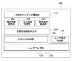
- FIG. 4is a block diagram showing the configuration of the information processing device 120.
- the information processing apparatus 120includes a 3D content storage unit 121, a viewpoint position determination unit 122, an attention area identification unit 123, a display space acquisition unit 124, a change processing execution determination unit 125, a 3D model control unit 126, a user A viewpoint detection unit 127 and a rendering unit 128 are provided.
- the 3D model control unit 126 and the rendering unit 128are collectively referred to as a display control unit 129 .
- These configurations of the information processing device 120are functional configurations realized by cooperation of hardware and software.
- the 3D content holding unit 121holds 3D content.
- 3D contentis content that includes at least information about the 3D model M, and the information about the 3D model M includes the shape and arrangement of the 3D model M. Also, the 3D content includes a “specified viewpoint position”.
- FIG. 5is a schematic diagram showing the 3D model M and the specified viewpoint position P. As shown in FIG.
- the 3D model Mis shown in FIG.
- a creator of 3D contentcan give camera work to the 3D model M in order to allow the user to view the 3D model M from an intended viewpoint position.
- Cameraworkmeans a function of automatically moving a specified viewpoint position P specified by the content creator's intention and changing the viewing angle of the 3D model M.
- the designated viewpoint position Pis indicated by the seat S, and the 3D model M photographed by the camera C fixed to the seat S is the 3D model M viewed from the designated viewpoint position P.
- the 3D model M viewed from the designated viewpoint position Pis displayed on the spatial reproduction display 110, the user visually recognizes the change in the angle of the 3D model M viewed from the designated viewpoint position P as the designated viewpoint position P moves. be able to.
- the user U himself/herselfcan move the head to slightly change the viewing angle of the 3D model M based on the specified viewpoint position P.
- FIG. 6is a schematic diagram showing changes in the 3D model M due to the specified viewpoint position P.
- FIG. 6Awhen the designated viewpoint position P is a viewpoint position P1 at a certain distance from the 3D model M, the user U visually recognizes the 3D model M1 on the spatial reproduction display 110 as shown in FIG. 6B.
- FIG. 6(a)when the specified viewpoint position P is a viewpoint position P2 which is more distant from the 3D model M than the viewpoint position P1, the user U can view the 3D image on the spatial reproduction display 110 as shown in FIG. 6(b). View model M2. Since the spatial reproduction display 110 displays the 3D model M2 smaller than the 3D model M1 and with a smaller parallax, the user U can perceive the 3D model M2 as if it were located farther than the 3D model M1.
- the viewpoint position determination unit 122determines the "display viewpoint position".
- the display viewpoint positionis a viewpoint position for the 3D model M, and the 3D model M viewed from the display viewpoint position is displayed on the spatial reproduction display 110 .
- FIG. 7is a schematic diagram showing the display viewpoint position T. As shown in FIG.
- the viewpoint position determination unit 122can determine the display viewpoint position T based on the designated viewpoint position P acquired from the 3D content storage unit 121 .
- the viewpoint position determination unit 122can set the specified viewpoint position P as the display viewpoint position T as shown in FIG. 7(a). Also, the viewpoint position determination unit 122 can set a viewpoint position different from the specified viewpoint position P as the display viewpoint position T, as shown in FIG. 7B. The viewpoint position determination unit 122 may move the display viewpoint position T according to the user's operation input or the passage of time. The viewpoint position determination unit 122 supplies the determined display viewpoint position T to the change processing execution determination unit 125 and the 3D model control unit 126 .
- the attention area specifying unit 123specifies the "attention area".
- the attention areaincludes at least part of the 3D model M and is an area that the user wants to pay attention to.
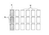
- 8 to 10are schematic diagrams showing the attention area R.
- FIG.In each figure below, the 3D model M is shown by a plurality of cylinders.
- the region of interest Rcan be a region containing one 3D model M as shown in FIG.
- the 3D models M included in the region of interest Rare referred to as 3D models of interest MR and shown with hatching.
- the attention area Rmay include a plurality of 3D models M as shown in FIG. 9, and the attention area R may include all of the 3D models M as shown in FIG.
- the attention area Rcan be specified by the creator of the 3D content and held in the 3D content holding unit 121, and the attention area specifying unit 123 can acquire the attention area R from the 3D content holding unit 121. can.
- the attention area specifying unit 123supplies the specified attention area R to the change processing execution determination unit 125 and the 3D model control unit 126 .
- the display space acquisition unit 124acquires the size of the display space 117 (see FIG. 2) in the spatial reproduction display 110 (hereinafter referred to as display space size).
- the display space sizeis the actual size of the display space 117 defined by the size of the display area 116 and the tilt angle.
- the display space acquisition unit 124acquires the display space size from the registry of the spatial reproduction display 110 or the like, and supplies the acquired display space size to the change processing execution determination unit 125 and the 3D model control unit 126 .
- the change processing execution determination unit 125determines whether or not to perform the change processing by the 3D model control unit 126 .
- the change processing execution determination unit 125determines whether or not to execute the change processing based on the display viewpoint position T, the attention area R, and the size of the display space 117 . Specifically, the change processing execution determination unit 125 determines whether or not the entire 3D model MR of interest can fit into the display space 117 when the 3D model MR of interest is viewed from the display viewpoint position T. can be done.
- FIG. 11is a schematic diagram showing a determination method by the change processing execution determination unit 125.
- FIG. 11(a)shows a case where the 3D model MR of interest is completely within the display space 117.
- FIGS. 11(b) and 11(c)show the case where the 3D model MR of interest does not completely fit in the display space 117.
- FIG. 11Awhen the 3D model M is completely within the display space 117, the change process execution determination unit 125 can determine that "change process is not performed.”
- the change processing execution determination unit 125determines that "change processing is to be performed" when the 3D model M does not completely fit in the display space 117. can be done.
- the change processing execution determination unit 125supplies the determination result to the 3D model control unit 126 .
- the 3D model control unit 126changes the position of the attention 3D model MR with respect to the display viewpoint position T into the display space 117 based on the display viewpoint position T, the attention area R and the display space 117 . Furthermore, the 3D model control unit 126 changes the size of the noted 3D model MR .
- the 3D model of interest MR before changing the position and sizeis referred to as a 3D model of interest MR1
- the 3D model of interest MR after changing the position and sizeis referred to as a 3D model of interest MR2 .
- FIG. 12is a schematic diagram showing the position and resizing of the 3D model of interest MR.
- FIG. 12(a)shows a state in which the 3D model of interest MR1 is positioned outside the display space 117, and the distance between the display viewpoint position T and the 3D model of interest MR1 is indicated as a distance L1.
- FIG. 12Bshows a state in which the 3D model of interest MR2 is positioned within the display space 117, and the distance between the display viewpoint position T and the 3D model of interest MR2 is indicated as a distance L2.
- the distance between the display viewpoint position T and the target 3D model MRcan be the distance between the display viewpoint position T and the center of gravity of the target 3D model MR .
- the 3D model control unit 126reduces the distance between the display viewpoint position T and the 3D model MR of interest at a first ratio, changes the position of the 3D model MR of interest within the display space 117, and changes the size of the 3D model MR of interest. is reduced by a second ratio.
- the second ratiocan be the same ratio as the first ratio.
- the 3D model control unit 126reduces the distance between the display viewpoint position T and the 3D model MR of interest from the distance L1 to the distance L2, and changes the position of the 3D model MR of interest as shown in FIG. Change into display space 117 .
- the 3D model control unit 126reduces the 3D model of interest MR1 by the ratio (L2/L1) to obtain a 3D model of interest MR2 . Therefore, both the first ratio and the second ratio are the ratio (L2/L1).
- FIG. 13is a schematic diagram showing a specific example of a method for changing the size of the 3D model of interest MR .
- the size of the 3D model of interest MR1is represented by "2*L1*tan ⁇ ".
- the 3D model control unit 126can change the size of the 3D model MR2 of interest to "2*L2*tan ⁇ " by multiplying "2*L1*tan ⁇ " by the ratio (L2/L1).
- the spatial reproduction display 110has an optimum viewing distance and viewing angle recommended by the device manufacturer, and the distance L2 can be determined as a fixed value based on the viewing distance. It can also be assumed that the viewing angle is basically the front of the device.
- the 3D model control unit 126can change the position and size of the target 3D model MR .
- the 3D model control unit 126can also calculate the position and size of the 3D model of interest MR2 by using the display viewpoint position T, the area of interest R , and the size of the display space 117 by another calculation method. Specifically, the 3D model control unit 126 can set the second ratio as the ratio at which the entire target 3D model MR2 enters the display space 117 .
- FIG. 14is a schematic diagram showing an example of this calculation method.
- the 3D model control unit 126maintains the distance between the display viewpoint position T and the 3D model MR2 of interest as the distance L2, and adjusts the size of the 3D model MR2 of interest so that the entire 3D model MR2 of interest enters the display space 117. Shrink at the cutting ratio. Therefore, in this case, the first ratio is the ratio (L2/L1) and the second ratio is a ratio smaller than the ratio (L2/L1).
- the 3D model control unit 126can change the position and size of the 3D models M other than the 3D model of interest MR in the same manner as the 3D model of interest MR. That is, the 3D model control unit 126 can reduce the distance between the display viewpoint position T and the 3D model M at a first ratio, and reduce the size of the 3D model M at a second ratio. Note that the distance between the display viewpoint position T and the 3D model M can be the distance between the center of gravity of the display viewpoint position T and the 3D model M. FIG.
- FIG. 15 to 18are schematic diagrams showing how the 3D model controller 126 changes the position and size of the 3D model M.
- FIG. FIG. 15shows an example in which one of the 3D models M is the target 3D model MR.
- the 3D model control unit 126calculates the ratio of the distance between the 3D model MR of interest and the display viewpoint position T so that the 3D model MR2 of interest is positioned within the display space 117 as shown in FIG. Reduce the 3D model M.
- FIG. 16is a schematic diagram showing another example of changing the position and size of the 3D model M by the 3D model control unit 126.
- one of the 3D models Mis the target 3D model MR , and the position of the target 3D model MR is different from that in FIG.
- the 3D model control unit 126calculates the ratio of the distance between the 3D model MR of interest and the display viewpoint position T so that the 3D model MR2 of interest is positioned within the display space 117 as shown in FIG. Reduce the 3D model M. Since the position of the target 3D model M R is different from the example of FIG. 15, the position and size change of the 3D model M are also different.
- FIG. 17is a schematic diagram showing another example of changing the position and size of the 3D model M by the 3D model control unit 126.
- the 3D model control unit 126controls the target 3D model M R so that the target 3D model M R2 is positioned within the display space 117 .
- a ratio of the distance to the display viewpoint position Tis calculated, and the 3D model M is reduced by that ratio. If the entire 3D model MR of interest does not fit in the display space 117 even after reduction, the 3D model is further reduced at a ratio that allows the entire 3D model MR of interest to fit in the display space 117 .
- FIG. 18is a schematic diagram showing another example of changing the position and size of the 3D model M by the 3D model control unit 126.
- the 3D model control unit 126controls the 3D models of interest MR so that the 3D model of interest MR2 is positioned within the display space 117.
- a ratio of the distance to the display viewpoint position Tis calculated, and the 3D model M is reduced by that ratio. If the entire 3D model MR of interest does not fit in the display space 117 even after reduction, the 3D model is further reduced at a ratio that allows the entire 3D model MR of interest to fit in the display space 117 .
- the 3D model control unit 126changes the position of the 3D model of interest MR with respect to the display viewpoint position T within the display space 117 and changes the size of the 3D model of interest MR . Also, the 3D model control unit 126 can change the position and size of the 3D models M other than the 3D model of interest MR in the same manner as the 3D model of interest MR. The 3D model control unit 126 supplies the change processing result of the 3D model M, that is, the position and size of the 3D model M after change to the rendering unit 128 .
- the user viewpoint detection unit 127detects the user U's viewpoint.
- the user viewpoint detection unit 127can perform image processing on the image captured by the camera 112 and detect the viewpoint of the user U in real time.
- the user viewpoint detection unit 127supplies the viewpoint detection result to the rendering unit 128 .
- the rendering unit 128renders the 3D model M to generate a left-eye model image and a right-eye model image.
- the rendering unit 128renders the 3D model M after the change processing based on the change processing result of the 3D model M supplied from the 3D model control unit 126 .
- the rendering unit 128executes rendering by reflecting the viewpoint detection result supplied from the user viewpoint detection unit 127, and can change the orientation of the 3D model according to the user's viewpoint position.
- the rendering unit 128supplies the generated left-eye model image and right-eye model image to the display panel 113 and causes the display panel 113 to display them.
- the information processing device 120has the configuration described above. Note that the configuration of the information processing device 120 is not limited to the one described above, and may be configured as follows.
- the attention area specifying unit 123acquires the attention area R specified in the 3D content holding unit 121, but the attention area specifying unit 123 specifies the attention area R based on the user's viewpoint detection result. good too.
- the attention area identification unit 123can acquire the viewpoint detection result from the user viewpoint detection unit 127 and set the attention area R as the area where the user is gazing.
- the attention area specifying unit 123may acquire attention areas set by a plurality of users viewing the same 3D content from the cloud or the like, and specify the attention area R based on the acquired attention areas. As a result, the attention area R reflects the intentions of a plurality of users. Furthermore, the attention area specifying unit 123 may specify the attention area R according to the arrangement of the 3D models M, such as setting the attention area R to a region where the 3D models M are concentrated.
- the rendering unit 128executes rendering by reflecting the viewpoint detection result supplied from the user viewpoint detection unit 127 , but does not reflect the viewpoint detection result in rendering, and renders the 3D model supplied from the 3D model control unit 126 . Rendering may be performed based only on the position and size of the model M.
- FIG. 19is a flow chart showing the operation of the information processing device 120. As shown in FIG.
- the display space acquisition unit 124acquires the display space size (see FIG. 2) (St101).
- the display space acquisition unit 124supplies the acquired display space size to the change processing execution determination unit 125 and the 3D model control unit 126 .
- the viewpoint position determination unit 122determines the display viewpoint position T (see FIG. 7) (St102).
- the viewpoint position determination unit 122can set the specified viewpoint position P acquired from the 3D content holding unit 121 or the viewpoint position obtained by moving the specified viewpoint position P as the display viewpoint position T.
- FIG. The viewpoint position determination unit 122supplies the display viewpoint position T to the change processing execution determination unit 125 and the 3D model control unit 126 .
- the attention area identifying unit 123identifies the attention area R (see FIGS. 8 to 10) (St103).
- the attention area specifying unit 123may acquire the attention area R from the 3D content holding unit 121, or may specify the attention area R from the user's viewpoint detection result or the layout of the 3D model M.
- the attention area specifying unit 123supplies the attention area R to the change processing execution determination unit 125 and the 3D model control unit 126 .
- the change processing execution determination unit 125determines whether or not to execute the change processing by the 3D model control unit 126 (St104). The change processing execution determination unit 125 can make this determination based on whether or not the entire 3D model MR1 of interest can fit in the display space 117 (see FIG. 11).
- the 3D model control unit 126changes the position and size of the 3D model M (see FIG. 12), and changes the position and size of the 3D model M R1 . is moved into the display space 117 (St105).
- the 3D model control unit 126supplies the changed position and size of the 3D model M to the rendering unit 128 .
- the 3D model control unit 126transfers the position and size of the 3D model M to the rendering unit 128 without executing the change processing. supply.
- the user viewpoint detection unit 127detects the user's viewpoint position (St 106 ) and supplies the detected viewpoint position to the rendering unit 128 .
- the rendering unit 128executes rendering based on the position and size of the 3D model M supplied from the 3D model control unit 126 (St107). Also, the rendering unit 128 may perform rendering based on the position and size of the 3D model M and the viewpoint position supplied from the user viewpoint detection unit 127 .
- the information processing apparatus 120repeatedly executes St102 to St107. As a result, the 3D model M is displayed on the spatial reproduction display 110 , and the 3D model M R of interest is arranged in the display space 117 .
- the 3D model control unit 126executes change processing of the 3D model M when the entire 3D model M R1 of interest does not fit in the display space 117 (St104: Yes).
- the process of changing the 3D model Mmay be executed regardless of the determination result.
- the 3D model control unit 126can move the 3D model MR2 of interest to the central portion of the display space 117 .
- the spatial reproduction display system 100avoids such a situation and can present the 3D model MR of interest with excellent visibility to the user, thereby facilitating the interaction between the user U and the 3D model MR of interest. It is possible to improve the three-dimensional effect of the sheath and the 3D model MR of interest.
- 3D contentincludes existing 3D content such as CG (computer graphics) animation and games.
- the spatial reproduction display system 100can place the 3D model MR of interest in the display space 117 even in a 3D model space created for existing 3D content. This makes it possible to improve the easiness of interaction and the stereoscopic effect even in existing 3D content.
- the spatial reproduction display system 100is capable of rendering the 3D model MR of interest positioned within the display space 117 as described above.
- the spatial reproduction display system 100presents an image in which the attention 3D model M R is gradually separated, the display viewpoint position T is gradually separated from the 3D model M.
- FIG. 20is a schematic diagram showing the user U and the 3D model MR of interest. Assuming that the user U is viewing the spatial reproduction display 110 from the optimum viewing position in front of the spatial reproduction display 110, if the distance between the 3D model MR1 of interest and the display viewpoint position T is gradually increased, as shown in FIG. The user U will perceive the 3D model MR1 of interest as being positioned outside the display space 117 . In such a case, by applying the present technology, even if the distance between the 3D model of interest M R and the display viewpoint position T gradually increases, the user can see the 3D model of interest M in the display space 117 as shown in FIG. It is possible to recognize that R2 is always present.
- a virtual camerais placed in the virtual space in which the 3D model is placed, and camerawork is added to express it as 2D images.
- the original 3D contentis not designed to completely fit within the display space 117, but is made to fit within the display space 117 as much as possible to improve visibility. can be improved.
- the designated viewpoint position P preset in the 3D contentis the viewpoint position designated by the creator, so this designated viewpoint position P can be used as the display viewpoint position T. Furthermore, when the attention area specifying unit 123 sets the attention area R within the angle of view when the content is viewed from the display viewpoint position T, the present technology can be applied.
- the attention area specifying unit 123can set the attention area R within the angle of view seen from the display viewpoint position T as shown in FIG. .
- the viewpoint position determination unit 122can move the display viewpoint position T according to the passage of time, and the attention area specifying unit 123 can move the attention area R according to the passage of time.
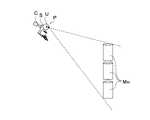
- FIG. 21is a schematic diagram showing the user U and the 3D model of interest MR1 , and shows a state in which the designated viewpoint position P is directed obliquely downward.
- 22 and 23are schematic diagrams showing the positional relationship between the display space 117 and the target 3D model MR . 21, when the designated viewpoint position P faces diagonally downward , as shown in FIG. may appear tilted. Depending on the orientation of the specified viewpoint position P, the 3D model MR1 of interest may not be positioned within the angle of view of the display space 117 as shown in FIG.
- FIG. FIG. 24is a schematic diagram showing a method of changing the position and direction of the display viewpoint position T.
- the viewpoint position determination unit 122moves the display viewpoint position T to a position that is horizontal with the midpoint A of the 3D model of interest MR1 , and moves the display viewpoint position T to a position that is horizontal. horizontally.
- FIG. 24A and 24Bthe viewpoint position determination unit 122 moves the display viewpoint position T to a position that is horizontal with the midpoint A of the 3D model of interest MR1 , and moves the display viewpoint position T to a position that is horizontal. horizontally.
- the display viewpoint position Tmoves so that the display space 117 is positioned on a straight line connecting the display viewpoint position T and the target 3D model MR1 , and the 3D model control unit 126 It becomes possible to arrange the 3D model M R2 of interest in the display space 117 .
- the information processing apparatus 120may move one or both of the display viewpoint position T and the attention area R as time elapses as described above.
- One or both of Rmay be moved.
- the viewpoint position determination unit 122can move the display viewpoint position T according to the user's operation input
- the attention area specifying unit 123can move the attention area R according to the user's operation input.
- the spatial reproduction display system 100is capable of expressing the 3D model of interest M R2 as if it were located in the display space 117, but the 3D model exists between the display viewpoint position T and the display space 117. sometimes.
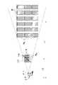
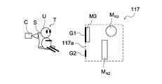
- FIG. 25is a schematic diagram showing the user U, the display space 117, and the 3D model M.
- the 3D model M R2 of interestis positioned within the display space 117 and the 3D model M3 is positioned from the inside to the outside of the display space 117 .
- the 3D model M4is located between the display space 117 and the display viewpoint position T.
- the spatial reproduction display system 100displays the 3D model M as it is, the user U will visually recognize the section (inside) of the 3D model M3.
- the display control unit 129can generate a 2D image by projecting the 3D model M located outside the display space 117 onto the surface of the display space 117 .
- FIG. 26is a schematic diagram showing generation of a 2D image by the 3D model control unit 126. As shown in FIG. As shown in the figure, the display control unit 129 generates an image G1 in which the 3D model M3 is projected onto the surface 117a of the display space 117 and an image G2 in which the 3D model M4 is projected onto the surface 117a.
- the usercan view the image G1 and the image G2 instead of the 3D model M3 and 3D model M4, and is prevented from viewing the section (inside) of the 3D model.
- the display control unit 129also displays the 3D model M located outside the display space 117 such as the back side of the display space 117. A 2D image projected onto the 117 surface can be generated.
- FIG. 27is a schematic diagram showing how the 3D model control unit 126 updates the 2D image. As shown in FIGS. 27A and 27B, when the user U's viewpoint position changes, the 3D model control unit 126 generates a 2D image according to the user U's viewpoint position.
- FIG. 28is a schematic diagram showing a 3D model M and a 2D image G subjected to blurring. By blurring the 2D image G as shown in the figure, the 3D model M existing in front of the display space 117 can be represented.
- the 3D model of interest MR1When the 3D model of interest MR1 is positioned in the display space 117 as shown in FIG. , the 3D model of interest MR2 is arranged in the display space 117 as shown in FIG. 29(c).
- the display control unit 129changes the background of the 3D model M as shown in FIGS. can be used as a background. This allows the user U to recognize that the 3D model of interest MR1 has moved away from the display viewpoint position T, rather than that the 3D model of interest MR has simply been reduced.
- the 3D model MR1 of interestis located in the display space 117, and the 3D model MR1 of interest is positioned at the display viewpoint position T as shown in FIG. 31(b).
- the 3D model of interest MR2is arranged in the display space 117 as shown in FIG. 31(c).
- the display control unit 129moves the 3D model MR2 of interest to the far side as indicated by the arrow during the process of changing the 3D model of interest MR1 to the 3D model MR2 of interest. After moving it slightly, it can be processed to return to its original position.
- This displayalso allows the user U to recognize that the 3D model MR1 has moved away from the display viewpoint position T.
- the 3D model MR1 of interestis located in the display space 117, and the 3D model MR1 of interest is positioned at the display viewpoint position T as shown in FIG. 32(b).
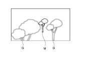
- the display control unit 129can display the background of the 3D model M so as to protrude outside the display space 117 without changing the background.
- the display control unit 129holds a background model such as a cloud separately from the 3D model M, renders the background model only in the display space 117, and expresses the background model flowing to the back side. can be done.
- This displayalso allows the user U to recognize that the 3D model MR1 has moved away from the display viewpoint position T.
- the 3D model MR1 of interestis located in the display space 117, and the 3D model MR1 of interest is positioned at the display viewpoint position T as shown in FIG. 33(b).
- the 3D model of interest MR2is placed in the display space 117 .
- the display control unit 129sets the distance between the 3D model MR of interest and the display viewpoint position T to the 3D model MR of interest as a character string or a display object such as a meter. can be displayed by This display also allows the user U to recognize that the 3D model MR1 has moved away from the display viewpoint position T.
- the display space acquisition unit 124acquires the size of the display space 117 as described above.
- the size of the display space 117may be changed.
- FIG. 34is a schematic diagram showing resizing of the display space 117. As shown in FIG. As shown in the figure, the spatial reproduction display 110 can change the size of the display space 117 by adjusting the tilt angle of the display area 116 .
- the display space acquisition unit 124acquires the new size of the display space 117 and supplies it to the change processing execution determination unit 125 and the 3D model control unit 126.
- the change processing execution determination unit 125 and the 3D model control unit 126can execute the above processing based on the new size of the display space 117 .
- the space reproduction display 110can be used in the spatial reproduction display 110 that enables stereoscopic display as if the 3D model M actually exists in the display space 117 .
- the space reproduction display 110is not limited to the one that exists in the real space, but a space reproduction that is virtually arranged in a space formed by AR (Augmented Reality) glasses, VR (Virtual Reality), and HMD (Head Mounted Display). It may be a display.
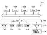
- FIG. 35is a schematic diagram showing this hardware configuration.
- the information processing device 120incorporates a CPU (Central Processing Unit) 1001 and a GPU (Graphics Processing Unit) 1002 .
- An input/output interface 1006is connected to the CPU 1001 and GPU 1002 via a bus 1005 .
- a ROM (Read Only Memory) 1003 and a RAM (Random Access Memory) 1004are connected to the bus 1005 .
- the input/output interface 1006includes an input unit 1007 including input devices such as a keyboard and a mouse for the user to input operation commands, an output unit 1008 for outputting a processing operation screen and images of processing results to a display device, and programs and various data.
- a removable storage medium 1012such as a magnetic disk, optical disk, magneto-optical disk, or semiconductor memory.
- the CPU 1001reads a program stored in the ROM 1003 or a removable storage medium 1012 such as a magnetic disk, an optical disk, a magneto-optical disk, or a semiconductor memory, is installed in the storage unit 1009, and is loaded from the storage unit 1009 to the RAM 1004. Various processes are executed according to the program.
- the RAM 1004also stores data necessary for the CPU 1001 to execute various types of processing.
- the GPU 1002receives control from the CPU 1001 and executes calculation processing necessary for image drawing.
- the CPU 1001loads, for example, a program stored in the storage unit 1009 into the RAM 1004 via the input/output interface 1006 and the bus 1005, and executes the program.
- a program stored in the storage unit 1009into the RAM 1004 via the input/output interface 1006 and the bus 1005, and executes the program.
- a series of processes described aboveare performed.
- a program executed by the information processing device 120can be provided by being recorded on a removable storage medium 1012 such as a package medium, for example. Also, the program can be provided via a wired or wireless transmission medium such as a local area network, the Internet, or digital satellite broadcasting.
- the programcan be installed in the storage unit 1009 via the input/output interface 1006 by loading the removable storage medium 1012 into the drive 1011 . Also, the program can be received by the communication unit 1010 and installed in the storage unit 1009 via a wired or wireless transmission medium. In addition, programs can be installed in the ROM 1003 and the storage unit 1009 in advance.
- the program executed by the information processing device 120may be a program in which processing is performed in chronological order according to the order described in the present disclosure, or may be performed in parallel or as necessary when called. It may be a program in which processing is performed with timing.
- the hardware configuration of the information processing device 120may not be all mounted in one device, and the information processing device 120 may be configured by a plurality of devices. Alternatively, it may be installed in a part of the hardware configuration of the information processing device 120 or in a plurality of devices connected via a network.
- the present technologycan also have the following configuration.
- a viewpoint position determination unitthat determines a viewpoint position for the 3D model in 3D content presented by a spatial reproduction display capable of stereoscopically displaying the 3D model; a region-of-interest identification unit that identifies a region of interest including at least part of the 3D model; a display space acquisition unit that acquires the size of a display space for displaying the 3D model on the spatial reproduction display;
- the 3D model included in the attention areais the attention 3D model
- the position of the attention 3D model with respect to the viewpoint positionis changed within the display space based on the viewpoint position, the attention area, and the size of the display space.
- the display control unitchanges the position of the 3D model of interest within the display space by reducing the distance between the viewpoint position and the 3D model of interest by a first ratio, and reduces the size of the 3D model of interest to the size of the 3D model of interest.
- the display control unitchanges the position of the 3D model of interest within the display space by reducing the distance between the viewpoint position and the 3D model of interest by a first ratio, and changes the size of the 3D model of interest to the size of the 3D model of interest.
- An information processing devicethat shrinks the entire 3D model at a second ratio that fits within the display space.
- the information processing apparatuswherein the display control unit reduces the distance between the viewpoint position and the 3D model at the first ratio, and reduces the size of the 3D model at the second ratio.
- the information processing deviceaccording to any one of (1) to (4) above, The information processing apparatus, wherein the viewpoint position determination unit moves the viewpoint position according to an operation input by a user.
- the attention area specifying unitmoves the attention area according to an operation input by a user.
- the information processing deviceaccording to any one of (1) to (6) above, The information processing apparatus, wherein the viewpoint position determination unit moves the viewpoint position according to the passage of time.
- the information processing deviceaccording to any one of (1) to (7) above, The information processing apparatus, wherein the attention area specifying unit moves the attention area over time.
- the display control unitgenerates a 2D image by projecting the 3D model located outside the display space onto a surface of the display space, and causes the spatial reproduction display to display the 2D image.
- the display control unitprojects the 3D model located between the viewpoint position and the display space onto a surface of the display space on the viewpoint position side to generate the 2D image.
- the information processing device(11) The information processing device according to (10) above, The information processing device, wherein the display control unit performs a blurring process on the 2D original image. (12) The information processing device according to any one of (1) to (11) above, The information processing apparatus, wherein the viewpoint position determination unit sets the viewpoint position specified in the 3D content as the viewpoint position. (13) The information processing device according to any one of (1) to (11) above, The viewpoint position determination unit moves the viewpoint position specified in the 3D content so that the display space is positioned on a straight line connecting the viewpoint position and the 3D model of interest, and sets the viewpoint position to the viewpoint position. .
- the information processing deviceaccording to any one of (1) to (13) above, The information processing apparatus, wherein the attention area specifying unit specifies an attention area specified in the 3D content as the attention area.
- the attention area identifying unitidentifies the attention area based on a user's viewpoint detection result.
- the attention area identifying unitidentifies the attention area based on the arrangement of the 3D model. Information processing apparatus.
- the display control unitgenerates a right-eye model image and a left-eye model image, which are parallax images of the 3D model viewed from the viewpoint position, and reproduces the right-eye model image and the left-eye model image in the space.
- An information processing devicethat stereoscopically displays the 3D model by displaying it on a display.
- the information processing apparatuswherein the display control unit changes the orientation of the 3D model according to a user's viewpoint detection result.
- a viewpoint position determination unitthat determines a viewpoint position for the 3D model in 3D content presented by a spatial reproduction display capable of stereoscopically displaying the 3D model; a region-of-interest identification unit that identifies a region of interest including at least part of the 3D model; a display space acquisition unit that acquires the size of a display space for displaying the 3D model on the spatial reproduction display; Assuming that the 3D model included in the attention area is the attention 3D model, the position of the attention 3D model with respect to the viewpoint position is changed within the display space based on the viewpoint position, the attention area, and the size of the display space.
- DESCRIPTION OF SYMBOLS 100Spatial reproduction display system 110
- Spatial reproduction display 116Display area 117... Display space 120
- Information processing apparatus121
- 3D content holding part122
- Viewpoint position determination part123
- Attention area specification part124
- Display space acquisition part125
- Change processing execution determination unit126
- 3D model control unit127 user viewpoint detection unit 128 rendering unit 129 display control unit
Landscapes
- Engineering & Computer Science (AREA)
- Physics & Mathematics (AREA)
- General Physics & Mathematics (AREA)
- Theoretical Computer Science (AREA)
- Multimedia (AREA)
- Signal Processing (AREA)
- Computer Hardware Design (AREA)
- Architecture (AREA)
- Computer Graphics (AREA)
- General Engineering & Computer Science (AREA)
- Software Systems (AREA)
- Processing Or Creating Images (AREA)
Abstract
Description
Translated fromJapanese本技術は、空間再現ディスプレイにより立体視表示される3Dモデルを制御する情報処理装置、プログラム及び情報処理方法に関する。The present technology relates to an information processing device, a program, and an information processing method for controlling a 3D model stereoscopically displayed on a spatial reproduction display.
空間再現ディスプレイは、ディスプレイを視認するユーザに視差を有する右目用画像と左眼用画像を提示し、裸眼での3Dモデルの立体視表示を可能とするディスプレイである。ユーザは特定の表示空間内に3Dモデルが実在するかのように認識することができる。立体視表示される3Dモデルの制御に関する技術として例えば特許文献1には、3Dモデルの視認性向上のため、左右の目の映像に差がない(視差がない)ディスプレイ面と同じ奥行き位置に3Dモデル位置を調整する技術が開示されている。A spatial reproduction display is a display that presents an image for the right eye and an image for the left eye that have parallax to the user viewing the display, enabling stereoscopic display of a 3D model with the naked eye. The user can perceive the 3D model as if it actually existed in a specific display space. As a technology related to the control of a 3D model displayed stereoscopically, for example,
空間再現ディスプレイでは上記のように、特定の表示空間において3Dモデルが立体視表示される。ここで、3Dモデルの配置や視点によっては3Dモデルが表示空間からはみ出すおそれがあり、ユーザが違和感を覚えたり、3Dモデルの立体感が低下したりするおそれがある。特許文献1に記載の構成では、ディスプレイ面に合わせた奥行き位置の調整は考慮しているものの、表示空間からのはみ出しを修正することはできない。As described above, the spatial reproduction display stereoscopically displays a 3D model in a specific display space. Here, depending on the arrangement of the 3D model and the viewpoint, the 3D model may protrude from the display space, which may cause the user to feel uncomfortable or reduce the three-dimensional effect of the 3D model. In the configuration described in
以上のような事情に鑑み、本技術の目的は、空間再現ディスプレイにより視認性に優れた3Dモデルの立体視表示を行うことが可能な情報処理装置、プログラム及び情報処理方法を提供することにある。In view of the circumstances as described above, an object of the present technology is to provide an information processing device, a program, and an information processing method capable of stereoscopically displaying a 3D model with excellent visibility on a spatial reproduction display. .
上記目的を達成するため、本技術に係る情報処理装置は、視点位置決定部と、注目領域特定部と、表示空間取得部と、表示制御部とを具備する。
上記視点位置決定部は、3Dモデルの立体視表示が可能な空間再現ディスプレイによって提示される3Dコンテンツにおいて、上記3Dモデルに対する視点位置を決定する。
上記注目領域特定部は、上記3Dモデルの少なくとも一部を含む注目領域を特定する。
上記表示空間取得部は、上記空間再現ディスプレイにおいて上記3Dモデルを表示するための表示空間のサイズを取得する。
上記表示制御部は、上記注目領域に含まれる上記3Dモデルを注目3Dモデルとすると、上記視点位置、上記注目領域及び上記表示空間のサイズに基づいて、上記視点位置に対する上記注目3Dモデルの位置を上記表示空間内に変更し、上記空間再現ディスプレイに上記3Dモデルを立体視表示させる。In order to achieve the above object, an information processing apparatus according to the present technology includes a viewpoint position determining unit, an attention area specifying unit, a display space acquiring unit, and a display control unit.
The viewpoint position determination unit determines a viewpoint position for the 3D model in 3D content presented by a spatial reproduction display capable of stereoscopically displaying the 3D model.
The attention area identifying unit identifies an attention area including at least part of the 3D model.
The display space acquisition unit acquires the size of a display space for displaying the 3D model on the spatial reproduction display.
Assuming that the 3D model included in the attention area is the attention 3D model, the display control unit determines the position of the attention 3D model with respect to the viewpoint position based on the viewpoint position, the attention area, and the size of the display space. The display space is changed, and the 3D model is stereoscopically displayed on the spatial reproduction display.
上記表示制御部は、上記視点位置と上記注目3Dモデルの距離を第1の比率で縮小することにより上記注目3Dモデルの位置を上記表示空間内に変更し、上記注目3Dモデルのサイズを上記第1の比率と同じ第2の比率で縮小してもよい。The display control unit changes the position of the 3D model of interest within the display space by reducing the distance between the viewpoint position and the 3D model of interest by a first ratio, and reduces the size of the 3D model of interest to the size of the 3D model of interest. It may be scaled down by a second ratio that is the same as the one ratio.
上記表示制御部は、上記視点位置と上記注目3Dモデルの距離を第1の比率で縮小することにより上記注目3Dモデルの位置を上記表示空間内に変更し、上記注目3Dモデルのサイズを上記注目3Dモデルの全体が上記表示空間に入る第2の比率で縮小してもよい。The display control unit changes the position of the 3D model of interest within the display space by reducing the distance between the viewpoint position and the 3D model of interest by a first ratio, and changes the size of the 3D model of interest to the size of the 3D model of interest. The entire 3D model may be scaled down by a second ratio to fit the display space.
上記表示制御部は、上記視点位置と上記3Dモデルの距離を上記第1の比率で縮小し、上記3Dモデルのサイズを上記第2の比率で縮小してもよい。The display control unit may reduce the distance between the viewpoint position and the 3D model at the first ratio, and reduce the size of the 3D model at the second ratio.
上記視点位置決定部は、ユーザによる操作入力に応じて上記視点位置を移動させてもよい。The viewpoint position determination unit may move the viewpoint position according to an operation input by the user.
上記注目領域特定部は、ユーザによる操作入力に応じて上記注目領域を移動させてもよい。The attention area specifying unit may move the attention area according to an operation input by the user.
上記視点位置決定部は、時間経過に応じて上記視点位置を移動させてもよい。The viewpoint position determining unit may move the viewpoint position according to the passage of time.
上記注目領域特定部は、時間経過に応じて上記注目領域を移動させてもよい。The attention area specifying unit may move the attention area over time.
上記表示制御部は、上記表示空間の外に位置する上記3Dモデルを上記表示空間の表面に投射した2D画像を生成し、上記空間再現ディスプレイに上記2D画像を表示させてもよい。The display control unit may generate a 2D image by projecting the 3D model located outside the display space onto the surface of the display space, and display the 2D image on the spatial reproduction display.
上記表示制御部は、上記視点位置と上記表示空間の間に位置する上記3Dモデルを上記表示空間の上記視点位置側の表面に投射して上記2D画像を生成してもよい。The display control unit may generate the 2D image by projecting the 3D model located between the viewpoint position and the display space onto the surface of the display space on the viewpoint position side.
上記表示制御部は、上記2D元画像にぼかし処理を施してもよい。The display control unit may apply blurring processing to the 2D original image.
上記視点位置決定部は、上記3Dコンテンツにおいて指定されている視点位置を上記視点位置としてもよい。The viewpoint position determination unit may set the viewpoint position specified in the 3D content as the viewpoint position.
上記視点位置決定部は、上記3Dコンテンツにおいて指定されている視点位置を、視点位置と上記注目3Dモデルを結ぶ直線上に上記表示空間が位置するように移動させて上記視点位置としてもよい。The viewpoint position determination unit may move the viewpoint position specified in the 3D content so that the display space is positioned on a straight line connecting the viewpoint position and the 3D model of interest to set the viewpoint position.
上記注目領域特定部は、上記3Dコンテンツにおいて指定されている注目領域を上記注目領域として特定してもよい。The attention area specifying unit may specify the attention area specified in the 3D content as the attention area.
上記注目領域特定部は、ユーザの視点検出結果に基づいて上記注目領域を特定してもよい。The attention area specifying unit may specify the attention area based on a user's viewpoint detection result.
上記注目領域特定部は、上記3Dモデルの配置に基づいて上記注目領域を特定してもよい。The attention area specifying unit may specify the attention area based on the arrangement of the 3D model.
上記表示制御部は、上記視点位置から見た上記3Dモデルの視差画像である右目用モデル画像と左眼用モデル画像を生成し、上記右目用モデル画像と上記左眼用モデル画像を上記空間再現ディスプレイに表示させることで上記3Dモデルを立体視表示させてもよい。The display control unit generates a right-eye model image and a left-eye model image, which are parallax images of the 3D model viewed from the viewpoint position, and reproduces the right-eye model image and the left-eye model image in the space. The 3D model may be stereoscopically displayed by displaying it on a display.
上記表示制御部は、ユーザの視点検出結果に応じて上記3Dモデルの向きを変化させてもよい。The display control unit may change the orientation of the 3D model according to the user's viewpoint detection result.
上記目的を達成するため、本技術に係るプログラムは、視点位置決定部と、注目領域特定部と、表示空間取得部と、表示制御部として情報処理装置を動作させる。
上記視点位置決定部は、3Dモデルの立体視表示が可能な空間再現ディスプレイによって提示される3Dコンテンツにおいて、上記3Dモデルに対する視点位置を決定する。
上記注目領域特定部は、上記3Dモデルの少なくとも一部を含む注目領域を特定する。
上記表示空間取得部は、上記空間再現ディスプレイにおいて上記3Dモデルを表示するための表示空間のサイズを取得する。
上記表示制御部は、上記注目領域に含まれる上記3Dモデルを注目3Dモデルとすると、上記視点位置、上記注目領域及び上記表示空間のサイズに基づいて、上記視点位置に対する上記注目3Dモデルの位置を上記表示空間内に変更し、上記空間再現ディスプレイに上記3Dモデルを立体視表示させる。In order to achieve the above object, a program according to the present technology causes an information processing apparatus to operate as a viewpoint position determination unit, an attention area identification unit, a display space acquisition unit, and a display control unit.
The viewpoint position determination unit determines a viewpoint position for the 3D model in 3D content presented by a spatial reproduction display capable of stereoscopically displaying the 3D model.
The attention area identifying unit identifies an attention area including at least part of the 3D model.
The display space acquisition unit acquires the size of a display space for displaying the 3D model on the spatial reproduction display.
Assuming that the 3D model included in the attention area is the attention 3D model, the display control unit determines the position of the attention 3D model with respect to the viewpoint position based on the viewpoint position, the attention area, and the size of the display space. The display space is changed, and the 3D model is stereoscopically displayed on the spatial reproduction display.
上記目的を達成するため、本技術に係る情報処理方法は、
3Dモデルの立体視表示が可能な空間再現ディスプレイによって提示される3Dコンテンツにおいて、上記3Dモデルに対する視点位置を決定し、
上記3Dモデルの少なくとも一部を含む注目領域を特定し、
上記空間再現ディスプレイにおいて上記3Dモデルを表示するための表示空間のサイズを取得し、
上記注目領域に含まれる上記3Dモデルを注目3Dモデルとすると、上記視点位置、上記注目領域及び上記表示空間のサイズに基づいて、上記視点位置に対する上記注目3Dモデルの位置を上記表示空間内に変更し、上記空間再現ディスプレイに上記3Dモデルを立体視表示させる。In order to achieve the above object, the information processing method according to the present technology includes:
Determining a viewpoint position for the 3D model in 3D content presented by a spatial reproduction display capable of stereoscopically displaying the 3D model;
identifying a region of interest that includes at least a portion of the 3D model;
obtaining the size of the display space for displaying the 3D model on the spatial reproduction display;
Assuming that the 3D model included in the attention area is the attention 3D model, the position of the attention 3D model with respect to the viewpoint position is changed within the display space based on the viewpoint position, the attention area, and the size of the display space. and stereoscopically display the 3D model on the spatial reproduction display.
本技術の実施形態に係る空間再現ディスプレイシステムについて説明する。A spatial reproduction display system according to an embodiment of the present technology will be described.
[空間再現ディスプレイシステムの構成]
図1は、本実施形態に係る空間再現ディスプレイシステム100の模式図である。同図に示すように空間再現ディスプレイシステム100は空間再現ディスプレイ110及び情報処理装置120を備える。空間再現ディスプレイ110と情報処理装置120は、有線又は無線により接続されており、ネットワークを介して接続されていてもよい。また、情報処理装置120は空間再現ディスプレイ110と一体的に構成されていてもよい。[Configuration of Spatial Reproduction Display System]
FIG. 1 is a schematic diagram of a spatial
[空間再現ディスプレイの構成]
図2は、空間再現ディスプレイ110の斜視図である。空間再現ディスプレイ110は、3DモデルMの立体視表示を行うディスプレイである。空間再現ディスプレイ110は、例えばテーブル等に載置して用いられる据え置き型の装置であり、空間再現ディスプレイ110を目視するユーザに、映像コンテンツ等を構成する3DモデルMを立体的に表示することができる。[Configuration of Spatial Reproduction Display]
FIG. 2 is a perspective view of the
空間再現ディスプレイ110は、ライトフィールドディスプレイであるものとすることができる。ライトフィールドディスプレイは、ユーザの視点の位置に合わせて、動的に左右の視差画像を生成するディスプレイである。これらの視差画像をユーザの左眼及び右眼に向けてそれぞれ表示することで、裸眼による立体視(ステレオ立体視)表示が実現される。The
具体的には空間再現ディスプレイ110は、図2に示すように筐体111、カメラ112、表示パネル113及びレンチキュラーレンズ114を具備する。筐体111は、空間再現ディスプレイ110の各部を収容する筐体であり、傾斜面115を有する。傾斜面115は、空間再現ディスプレイ110が載置される載置面に対して傾斜するように構成される。傾斜面115には、カメラ112及び表示パネル113が配置される。Specifically, the
カメラ112は、表示パネル113を目視するユーザの顔を撮影する撮影素子である。カメラ112は、例えばユーザの顔を撮影可能な位置に適宜配置される。図2では、傾斜面115において表示パネル113の中央の上側となる位置にカメラ112が配置されている。カメラ112としては、例えばCMOS(Complementary Metal-Oxide Semiconductor)センサやCCD(Charge Coupled Device)センサ等のイメージセンサ等を備えるデジタルカメラが用いられる。カメラ112の具体的な構成は限定されず、例えばステレオカメラ等の多眼カメラが用いられてもよい。また赤外光を照射して赤外画像を撮影する赤外カメラや、測距センサとして機能するToFカメラ等がカメラ112として用いられてもよい。The
表示パネル113は、3DモデルMを立体視表示するための視差画像を表示する表示素子である。表示パネル113は、例えば平面視で矩形状のパネルであり、上記した傾斜面115に配置されている。即ち表示パネル113は、ユーザから見て傾斜した状態で配置されている。これにより、ユーザは、例えば水平方向や垂直方向から表示パネル113を目視しても3DモデルMを視認することができる。The display panel 113 is a display element that displays parallax images for displaying the 3D model M stereoscopically. The display panel 113 is, for example, a rectangular panel in plan view, and is arranged on the
表示パネル113としては、例えばLCD(Liquid Crystal Display)、PDP(Plasma Display Panel)、又は有機EL(Electro-Luminescence)パネル等の表示素子を用いることができる。表示パネル113において視差画像が表示される領域は、空間再現ディスプレイ110の表示領域116となる。図2には表示領域116が太い黒線の領域として模式的に図示されている。As the display panel 113, a display element such as an LCD (Liquid Crystal Display), a PDP (Plasma Display Panel), or an organic EL (Electro-Luminescence) panel can be used. The area where the parallax image is displayed on the display panel 113 is the
レンチキュラーレンズ114は、表示パネル113の表面(表示領域116)に貼付され、表示パネル113から出射した光線を特定の方向にのみ屈折させるレンズである。レンチキュラーレンズ114は、例えば細長い凸レンズが互いに隣接して配列された構造を有し、凸レンズの延在方向が表示パネル113の上下方向と一致するように配置される。表示パネル113には、例えばレンチキュラーレンズ114に合わせて短冊状に分割された左右の視差画像からなる2次元画像が表示される。この2次元画像を適宜構成することで、ユーザの左眼及び右眼に向けて対応する視差画像をそれぞれ表示することが可能となる。The lenticular lens 114 is a lens attached to the surface (display area 116) of the display panel 113, and refracts light rays emitted from the display panel 113 only in a specific direction. The lenticular lens 114 has, for example, a structure in which elongated convex lenses are arranged adjacent to each other, and are arranged so that the extending direction of the convex lenses coincides with the vertical direction of the display panel 113 . The display panel 113 displays, for example, a two-dimensional image composed of left and right parallax images divided into strips in accordance with the lenticular lens 114 . By appropriately constructing this two-dimensional image, it is possible to display the corresponding parallax images to the left eye and right eye of the user, respectively.
空間再現ディスプレイ110では、このように表示パネル113が備える表示画素毎に出射方向を制御するレンチキュラーレンズ114が設けられたレンチキュラーレンズ方式により立体視表示を実現するものとすることができる。この他にも、空間再現ディスプレイ110では立体視表示を実現するための方式は限定されない。例えば、1組の表示画素毎に遮蔽板を設けて各眼に入射する光線を分けるパララックスバリア方式が用いられてもよい。また、偏光眼鏡等を用いて視差画像を表示する偏光方式や、液晶眼鏡等を用いてフレームごとに視差画像を切り換えて表示するフレームシーケンシャル方式等が用いられてもよい。In the
空間再現ディスプレイ110は、表示パネル113の表示領域116に表示される左右の視差画像により、少なくとも1つの3DモデルMを立体的表示することが可能である。以下では、各3DモデルMを表す左眼用及び右眼用の視差画像を、左眼用モデル画像及び右眼用モデル画像と記載する。左眼用モデル画像及び右眼用モデル画像は、例えばある3DモデルMを左眼及び右眼に対応する位置から見た1組の画像である。したがって、表示領域116には、左眼用モデル画像及び右眼用モデル画像のペアが3DモデルMの数だけ表示される。このように、表示領域116は、ユーザの左眼及び右眼に対応させて3DモデルM毎に生成される左眼用モデル画像及び右眼用モデル画像のペアが表示される領域である。The
空間再現ディスプレイ110では、予め設定された空間内で3DモデルMが立体視表示される。以下この空間を表示空間117とする。図2では、表示空間117に対応する空間が点線を用いて模式的に図示されている。図3はユーザUが視認する3DモデルMを示す模式図である。同図に示すように空間再現ディスプレイ110を目視するユーザUは、表示領域116に表示された左眼用モデル画像及び右眼用モデル画像を視認することで、表示領域116の手前側及び奥側に3DモデルMが存在し、表示空間117に実際に3DモデルMが存在するかのように認識することができる。The
また、空間再現ディスプレイ110ではカメラ112によりユーザUの視点を検出し、検出結果に応じて左眼用モデル画像及び右眼用モデル画像を生成することができる。これによりユーザUが頭部を動かしたりすることによって視点を移動させると、それに応じて3DモデルMの向きが変化し、ユーザは実際に3DモデルMを目視しているかのように認識することができる。なお、空間再現ディスプレイ110は視点検出を実施せず、表示領域116を正面から視認した際に3DモデルMが立体視できるように左眼用モデル画像及び右眼用モデル画像を生成することも可能である。In addition, the
表示空間117としては、表示領域116の左右の短辺の各々が互いに向かい合う面の対角線となるような直方体形状の空間を用いることができる。また表示空間117の各面は、空間再現ディスプレイ110が配置される配置面に平行又は直交する面となるように設定される。これにより、例えば表示空間117における前後方向、上下方向、底面等を認識しやすくなる。なお表示空間117の形状は限定されず、例えば空間再現ディスプレイ110の用途等に応じて任意に設定することが可能である。As the
[情報処理装置の構成]
図4は情報処理装置120の構成を示すブロック図である。同図に示すように、情報処理装置120は3Dコンテンツ保持部121、視点位置決定部122、注目領域特定部123、表示空間取得部124、変更処理実施判断部125、3Dモデル制御部126、ユーザ視点検出部127及びレンダリング部128を備える。なお、3Dモデル制御部126とレンダリング部128を併せて表示制御部129とする。情報処理装置120のこれらの構成は、ハードウェアとソフトウェアの協働により実現される機能的構成である。[Configuration of information processing device]
FIG. 4 is a block diagram showing the configuration of the
3Dコンテンツ保持部121は、3Dコンテンツを保持する。3Dコンテンツは少なくとも3DモデルMに関する情報を含むコンテンツであり、3DモデルMに関する情報には3DモデルMの形状及び配置が含まれる。また、3Dコンテンツには「指定視点位置」が含まれる。図5は3DモデルM及び指定視点位置Pを示す模式図である。The 3D
図5において3DモデルMを示す。3Dコンテンツの制作者は、意図した視点位置からユーザに3DモデルMを視認させるために3DモデルMに対するカメラワークを付与することができる。カメラワークとは、コンテンツ制作者の意図により指定される指定視点位置Pが自動で動いて3DモデルMの視認アングルが変わる機能を意味する。The 3D model M is shown in FIG. A creator of 3D content can give camera work to the 3D model M in order to allow the user to view the 3D model M from an intended viewpoint position. Camerawork means a function of automatically moving a specified viewpoint position P specified by the content creator's intention and changing the viewing angle of the 3D model M. FIG.
図5では、指定視点位置Pを座席Sによって示し、座席Sに対して固定されたカメラCによって撮影された3DモデルMが、その指定視点位置Pから見た3DモデルMである。指定視点位置Pから見た3DモデルMが空間再現ディスプレイ110によって表示されると、指定視点位置Pの移動に伴って、ユーザは指定視点位置Pから見た3DモデルMのアングルの変化を視認することができる。また、ユーザU自身も指定視点位置Pをベースとして、頭部を動かして3DモデルMの視認アングルを若干変更することができる。In FIG. 5, the designated viewpoint position P is indicated by the seat S, and the 3D model M photographed by the camera C fixed to the seat S is the 3D model M viewed from the designated viewpoint position P. When the 3D model M viewed from the designated viewpoint position P is displayed on the
図6は、指定視点位置Pによる3DモデルMの変化を示す模式図である。図6(a)において指定視点位置Pが3DモデルMから一定距離の視点位置P1である場合、ユーザUは空間再現ディスプレイ110において図6(b)に示すように3DモデルM1を視認する。図6(a)に示すように指定視点位置Pが、視点位置P1より3DモデルMから離間した視点位置P2である場合、ユーザUは空間再現ディスプレイ110において図6(b)に示すように3DモデルM2を視認する。空間再現ディスプレイ110では3DモデルM2が3DモデルM1より小さく、かつ視差が小さくなるように表示されるため、ユーザUは3DモデルM2が3DモデルM1より遠くに位置するように認識することができる。FIG. 6 is a schematic diagram showing changes in the 3D model M due to the specified viewpoint position P. FIG. In FIG. 6A, when the designated viewpoint position P is a viewpoint position P1 at a certain distance from the 3D model M, the user U visually recognizes the 3D model M1 on the
視点位置決定部122は、「表示視点位置」を決定する。表示視点位置は、3DモデルMに対する視点位置であり、表示視点位置から見た3DモデルMが空間再現ディスプレイ110において表示される。図7は表示視点位置Tを示す模式図である。視点位置決定部122は、3Dコンテンツ保持部121から取得した指定視点位置Pに基づいて表示視点位置Tを決定することができる。The viewpoint
具体的には視点位置決定部122は、図7(a)に示すように指定視点位置Pを表示視点位置Tとすることができる。また、視点位置決定部122は、図7(b)に示すように指定視点位置Pとは異なる視点位置を表示視点位置Tとすることもできる。視点位置決定部122はユーザによる操作入力や時間経過に応じて表示視点位置Tを移動させてもよい。視点位置決定部122は決定した表示視点位置Tを変更処理実施判断部125及び3Dモデル制御部126に供給する。Specifically, the viewpoint
注目領域特定部123は、「注目領域」を特定する。注目領域は3DモデルMの少なくとも一部を含み、ユーザに注目してもらいたい領域である。図8乃至図10は注目領域Rを示す模式図である。なお、以下の各図では3DモデルMを複数の円柱によって示す。図8に示すように注目領域Rは1つの3DモデルMを含む領域とすることができる。以下、3DモデルMのうち、注目領域Rに含まれる3DモデルMを注目3DモデルMRとし、ハッチングを付して示す。図9に示すように注目領域Rは複数の3DモデルMを含むものであってもよく、図10に示すように注目領域Rは3DモデルMの全てを含むものであってもよい。The attention
注目領域Rは3Dコンテンツの制作者によって指定され、3Dコンテンツ保持部121に保持されているものとすることができ、注目領域特定部123は3Dコンテンツ保持部121から注目領域Rを取得することができる。注目領域特定部123は、特定した注目領域Rを変更処理実施判断部125及び3Dモデル制御部126に供給する。The attention area R can be specified by the creator of the 3D content and held in the 3D
表示空間取得部124は、空間再現ディスプレイ110における表示空間117(図2参照)のサイズ(以下、表示空間サイズ)を取得する。表示空間サイズは表示領域116のサイズ及び傾斜角度によって規定される表示空間117の実際のサイズである。表示空間取得部124は空間再現ディスプレイ110のレジストリ等から表示空間サイズを取得し、取得した表示空間サイズを変更処理実施判断部125及び3Dモデル制御部126に供給する。The display
変更処理実施判断部125は3Dモデル制御部126による変更処理を実施するか否かを判断する。変更処理実施判断部125は、表示視点位置T、注目領域R及び表示空間117のサイズに基づいて変更処理を実行するか否かを判断する。具体的には変更処理実施判断部125は、注目3DモデルMRを表示視点位置Tから見た場合に、注目3DモデルMRの全体が表示空間117に入り切るか否かによって判断を行うことができる。The change processing
図11は、変更処理実施判断部125による判定方法を示す模式図である。図11(a)は注目3DモデルMRが表示空間117に入り切っている場合を示す。図11(b)及び図11(c)は、注目3DモデルMRが表示空間117に入り切っていない場合を示す。変更処理実施判断部125は図11(a)に示すように、3DモデルMが表示空間117に入り切っている場合、「変更処理を実施しない」と判断することができる。また、変更処理実施判断部125は図11(b)及び図11(c)に示すように、3DモデルMが表示空間117に入り切っていない場合、「変更処理を実施する」と判断することができる。変更処理実施判断部125は判断結果を3Dモデル制御部126に供給する。FIG. 11 is a schematic diagram showing a determination method by the change processing
3Dモデル制御部126は表示視点位置T、注目領域R及び表示空間117に基づいて、表示視点位置Tに対する注目3DモデルMRの位置を表示空間117内に変更する。さらに3Dモデル制御部126は注目3DモデルMRのサイズを変更する。以下、位置及びサイズの変更前の注目3DモデルMRを注目3DモデルMR1とし、位置及びサイズの変更後の注目3DモデルMRを注目3DモデルMR2とする。The 3D
図12は注目3DモデルMRの位置及びサイズ変更を示す模式図である。図12(a)は注目3DモデルMR1が表示空間117外に位置する状態を示し、表示視点位置Tと注目3DモデルMR1の距離を距離L1として示す。図12(b)は注目3DモデルMR2が表示空間117内に位置する状態を示し、表示視点位置Tと注目3DモデルMR2の距離を距離L2として示す。なお、表示視点位置Tと注目3DモデルMRの距離は、表示視点位置Tと注目3DモデルMRの重心の距離とすることができる。FIG. 12 is a schematic diagram showing the position andresizing of the 3D model of interest MR. FIG. 12(a) shows a state in which the 3D model of interestMR1 is positioned outside the
3Dモデル制御部126は表示視点位置Tと注目3DモデルMRの距離を第1の比率で縮小して注目3DモデルMRの位置を表示空間117内に変更し、注目3DモデルMRのサイズを第2の比率で縮小する。第2の比率は第1の比率と同一の比率とすることができる。具体的には3Dモデル制御部126は、表示視点位置Tと注目3DモデルMRの距離を距離L1から距離L2に縮小し、図12(b)に示すように注目3DモデルMRの位置を表示空間117内に変更する。さらに、3Dモデル制御部126は、比率(L2/L1)で注目3DモデルMR1を縮小し、注目3DモデルMR2とする。したがって、第1の比率と第2の比率は共に比率(L2/L1)である。The 3D
図13は、注目3DモデルMRのサイズ変更方法の具体例を示す模式図である。同図に示すように表示視点位置Tと注目3DモデルMR1の距離が距離L1であるとき、注目3DモデルMR1のサイズは「2*L1*tanθ」で表される。3Dモデル制御部126は注目3DモデルMR2のサイズを、「2*L1*tanθ」に対して比率(L2/L1)を乗じた「2*L2*tanθ」に変更することができる。FIG. 13 is a schematic diagram showing a specific example of a method for changing the size of the 3D model of interestMR . As shown in the figure, when the distance between the display viewpoint position T and the 3D model of interestMR1 is the distance L1, the size of the 3D model of interestMR1 is represented by "2*L1*tan θ". The 3D
通常、空間再現ディスプレイ110には装置製作者が推奨する最適な視聴距離と視聴アングルが存在し、その視聴距離により距離L2は固定値として決めることができる。また、視聴アングルは基本的には装置の正面であると想定することができる。以上のように、3Dモデル制御部126は、注目3DモデルMRの位置及びイズを変更することができる。Usually, the
さらに、3Dモデル制御部126は表示視点位置T、注目領域R及び表示空間117のサイズを用いて他の算出方法によって注目3DモデルMR2の位置及びサイズを算出することもできる。具体的には3Dモデル制御部126は、第2の比率を注目3DモデルMR2の全体が表示空間117に入る比率とすることができる。Furthermore, the 3D
図14はこの算出方法の一例を示す模式図である。図14(a)に示すように、注目3DモデルMR2を距離L2の位置に移動させ、比率(L2/L1)で縮小しても、注目3DモデルMR2の全体が表示空間117に入り切らない場合がある。この場合、3Dモデル制御部126は、表示視点位置Tと注目3DモデルMR2の距離を距離L2としたまま、注目3DモデルMR2のサイズを注目3DモデルMR2の全体が表示空間117に入り切る比率で縮小する。したがって、この場合、第1の比率は比率(L2/L1)であり、第2の比率は比率(L2/L1)より小さい比率である。FIG. 14 is a schematic diagram showing an example of this calculation method. As shown in FIG. 14A, even if the 3D model of interestMR2 is moved to the position of the distance L2 and is reduced by the ratio (L2/L1), the entire 3D model of interestMR2 does not fit in the
さらに、3Dモデル制御部126は、注目3DモデルMR以外の3DモデルMについても注目3DモデルMRと同様に、位置及びサイズの変更を行うことができる。即ち3Dモデル制御部126は、表示視点位置Tと3DモデルMの距離を第1の比率で縮小し、3DモデルMのサイズを第2の比率で縮小することができる。なお、表示視点位置Tと3DモデルMの距離は、表示視点位置Tと3DモデルMの重心の距離とすることができる。Furthermore, the 3D
図15乃至図18は、3Dモデル制御部126による3DモデルMの位置及びサイズ変更を示す模式図である。図15は、3DモデルMの一つが注目3DモデルMRである例を示す。3Dモデル制御部126は、同図に示すように表示空間117内に注目3DモデルMR2が位置するように注目3DモデルMRの表示視点位置Tとの距離の比率を算出し、その比率で3DモデルMを縮小する。15 to 18 are schematic diagrams showing how the
図16は、3Dモデル制御部126による3DモデルMの位置及びサイズ変更の他の例を示す模式図である。同図に示すように、3DモデルMの一つが注目3DモデルMRであり、図15とは注目3DモデルMRの位置が異なる。3Dモデル制御部126は、同図に示すように表示空間117内に注目3DモデルMR2が位置するように注目3DモデルMRの表示視点位置Tとの距離の比率を算出し、その比率で3DモデルMを縮小する。図15の例とは注目3DモデルMRの位置が異なるため、3DモデルMの位置及びサイズ変更の態様も異なるものとなっている。FIG. 16 is a schematic diagram showing another example of changing the position and size of the 3D model M by the 3D
図17は、3Dモデル制御部126による3DモデルMの位置及びサイズ変更の他の例を示す模式図である。同図に示すように、複数の3DモデルMが注目3DモデルMRである場合、3Dモデル制御部126は、表示空間117内に注目3DモデルMR2が位置するように注目3DモデルMRの表示視点位置Tとの距離の比率を算出し、その比率で3DモデルMを縮小する。縮小しても注目3DモデルMRの全体が表示空間117に入り切らない場合、注目3DモデルMRの全体が表示空間117に入り切る比率でさらに3Dモデルを縮小する。FIG. 17 is a schematic diagram showing another example of changing the position and size of the 3D model M by the 3D
図18は、3Dモデル制御部126による3DモデルMの位置及びサイズ変更の他の例を示す模式図である。同図に示すように、全ての3DモデルMが注目3DモデルMRである場合、3Dモデル制御部126は、表示空間117内に注目3DモデルMR2が位置するように注目3DモデルMRの表示視点位置Tとの距離の比率を算出し、その比率で3DモデルMを縮小する。縮小しても注目3DモデルMRの全体が表示空間117に入り切らない場合、注目3DモデルMRの全体が表示空間117に入り切る比率でさらに3Dモデルを縮小する。FIG. 18 is a schematic diagram showing another example of changing the position and size of the 3D model M by the 3D
3Dモデル制御部126は以上のようにして、表示視点位置Tに対する注目3DモデルMRの位置を表示空間117内に変更すると共に注目3DモデルMRのサイズを変更する。また、3Dモデル制御部126は注目3DモデルMR以外の3DモデルMも注目3DモデルMRと同様に、位置及びサイズの変更を行うことができる。3Dモデル制御部126は3DモデルMの変更処理結果、即ち変更後の3DモデルMの位置及びサイズをレンダリング部128に供給する。As described above, the 3D
ユーザ視点検出部127は、ユーザUの視点を検出する。ユーザ視点検出部127はカメラ112によって撮像された画像に対して画像処理を施し、ユーザUの視点をリアルタイムで検出することができる。ユーザ視点検出部127は、視点検出結果をレンダリング部128に供給する。The user
レンダリング部128は、3DモデルMのレンダリングを実行し、左眼用モデル画像及び右眼用モデル画像を生成する。レンダリング部128は3Dモデル制御部126から供給された3DモデルMの変更処理結果に基づき、変更処理後の3DモデルMに対してレンダリングを実行する。この際、レンダリング部128はユーザ視点検出部127から供給された視点検出結果を反映させてレンダリングを実行し、ユーザの視点位置に応じて3Dモデルの向きを変えることができる。レンダリング部128は、生成した左眼用モデル画像及び右眼用モデル画像を表示パネル113に供給し、表示パネル113に表示させる。The
情報処理装置120は以上のような構成を有する。なお、情報処理装置120の構成は上述のものに限られず、以下のような構成であってもよい。The
上記説明において、注目領域特定部123は3Dコンテンツ保持部121において指定されている注目領域Rを取得するとしたが、注目領域特定部123はユーザの視点検出結果に基づいて注目領域Rを特定してもよい。具体的には注目領域特定部123はユーザ視点検出部127から視点検出結果を取得し、ユーザが注視している領域を注目領域Rとすることができる。In the above description, the attention
また、注目領域特定部123は、同一の3Dコンテンツを視聴する複数のユーザが設定していた注目領域をクラウド等から取得し、それに基づいて注目領域Rを特定してもよい。これにより、注目領域Rは複数のユーザの意図を反映したものとなる。さらに、注目領域特定部123は3DモデルMが集中している領域を注目領域Rとする等、3DモデルMの配置に応じて注目領域Rを特定してもよい。Also, the attention
また、レンダリング部128は、ユーザ視点検出部127から供給された視点検出結果を反映させてレンダリングを実行するとしたが、レンダリングに視点検出結果を反映させず、3Dモデル制御部126から供給された3DモデルMの位置及びサイズのみに基づいてレンダリングを実行してもよい。Also, the
[情報処理装置の動作]
情報処理装置120の動作について説明する。図19は、情報処理装置120の動作を示すフローチャートである。[Operation of information processing device]
The operation of the
3DモデルMの表示が指示されると、表示空間取得部124が表示空間サイズ(図2参照)を取得する(St101)。表示空間取得部124は、取得した表示空間サイズを変更処理実施判断部125及び3Dモデル制御部126に供給する。When the display of the 3D model M is instructed, the display
続いて、視点位置決定部122が表示視点位置T(図7参照)を決定する(St102)。視点位置決定部122は、3Dコンテンツ保持部121から取得した指定視点位置P又は指定視点位置Pを移動させた視点位置を表示視点位置Tとすることができる。視点位置決定部122は表示視点位置Tを変更処理実施判断部125及び3Dモデル制御部126に供給する。Subsequently, the viewpoint
続いて、注目領域特定部123が注目領域R(図8乃至図10参照)を特定する(St103)。注目領域特定部123は、3Dコンテンツ保持部121から注目領域Rを取得してもよく、ユーザの視点検出結果や3DモデルMの配置から注目領域Rを特定してもよい。注目領域特定部123は注目領域Rを変更処理実施判断部125及び3Dモデル制御部126に供給する。Subsequently, the attention
続いて、変更処理実施判断部125が3Dモデル制御部126による変更処理を実行するか否かを判断する(St104)。変更処理実施判断部125は注目3DモデルMR1の全体が表示空間117に入り切るか否か(図11参照)によってこの判断を行うことができる。Subsequently, the change processing
注目3DモデルMR1の全体が表示空間117に入り切らない場合(St104:Yes)、3Dモデル制御部126は3DモデルMの位置及びサイズ変更(図12参照)を実施し、注目3DモデルMRを表示空間117内に移動させる(St105)。3Dモデル制御部126は変更後の3DモデルMの位置及びサイズをレンダリング部128に供給する。一方、注目3DモデルMR1の全体が表示空間117に入り切っている場合(St104:No)、3Dモデル制御部126は変更処理を実行せずに3DモデルMの位置及びサイズをレンダリング部128に供給する。If the entire 3D model MR1 of interest does not fit in the display space 117 (St104: Yes), the 3D
続いてユーザ視点検出部127はユーザの視点位置を検出し(St106)、検出した視点位置をレンダリング部128に供給する。続いて、レンダリング部128は、3Dモデル制御部126から供給された3DモデルMの位置及びサイズに基づいてレンダリングを実行する(St107)。また、レンダリング部128は、3DモデルMの位置及びサイズとユーザ視点検出部127から供給された視点位置に基づいてレンダリングを実行してもよい。以降、情報処理装置120は上記St102からSt107を繰り返し実行する。これにより、空間再現ディスプレイ110において3DモデルMが表示され、注目3DモデルMRは表示空間117内に配置される。Subsequently, the user
なお、3Dモデル制御部126は、注目3DモデルMR1の全体が表示空間117に入り切らない場合(St104:Yes)に3DモデルMの変更処理を実行するとしたが、変更処理実施判断部125の判断結果に関わらず、3DモデルMの変更処理を実行してもよい。これにより3Dモデル制御部126は注目3DモデルMR2を表示空間117の中央部に移動させることが可能である。Note that the 3D
[空間再現ディスプレイシステムによる効果]
空間再現ディスプレイシステム100では上記のように、注目3DモデルMR1が表示視点位置Tから見て表示空間117からはみ出す場合、注目3DモデルMR1の位置及びサイズを変更し、注目3DモデルMR2を表示空間117に配置する。これにより、ユーザは表示空間117内に位置する注目3DモデルMR2を立体視することができる。[Effects of Spatial Reproduction Display System]
As described above, in the spatial
仮にユーザUが表示空間117からはみ出した注目3DモデルMRを視認すると、違和感を覚えたり、注目3DモデルMRの立体感が低下したりするおそれがある。一方、空間再現ディスプレイシステム100ではこのような状態を回避し、視認性に優れた注目3DモデルMRをユーザに提示することが可能であり、ユーザUと注目3DモデルMRのインタラクションのしやすさや、注目3DモデルMRの立体感を向上させることが可能である。If the user U sees the 3D modelMR of interest protruding from the
また、3Dコンテンツには空間再現ディスプレイのために作成された3Dコンテンツの他にもCG(computer graphics)アニメーションやゲームといった既存の3Dコンテンツがある。空間再現ディスプレイシステム100では既存の3Dコンテンツのために作成された3Dモデル空間においても注目3DモデルMRを表示空間117に配置することができる。これにより、既存の3Dコンテンツにおいてもインタラクションのしやすさや立体感の向上が実現可能である。In addition to 3D content created for spatial reproduction display, 3D content includes existing 3D content such as CG (computer graphics) animation and games. The spatial
[表示視点位置及び注目領域の移動について]
空間再現ディスプレイシステム100は上記のように注目3DモデルMRが表示空間117内に位置しているような表現が可能である。ここで、空間再現ディスプレイシステム100によって注目3DモデルMRが次第に離間していくような映像を提示する場合、3DモデルMから表示視点位置Tを次第に離間させていく事になる。[Regarding movement of display viewpoint position and attention area]
The spatial
図20はユーザU及び注目3DモデルMRを示す模式図である。空間再現ディスプレイ110の正面の最適な視聴位置からユーザUが空間再現ディスプレイ110を視認しているとして、注目3DモデルMR1と表示視点位置Tの距離を次第に離間させると、図20に示すようにユーザUは、表示空間117外に注目3DモデルMR1が位置するように認識してしまう。このような場合に、本技術を適用することにより、注目3DモデルMRと表示視点位置Tの距離が次第に離間しても、図20に示すようにユーザは表示空間117内に注目3DモデルMR2が常に存在するように認識することが可能である。FIG. 20 is a schematic diagram showing the user U and the 3D modelMR of interest. Assuming that the user U is viewing the
また、CGアニメーションや3Dコンピュータゲームでは、3Dモデルが配置された仮想空間に対して仮想カメラを配置してカメラワークを付与することで2D映像として表現していることが多い。このような3Dコンテンツを空間再現ディスプレイ110で表示する場合、元の3Dコンテンツは表示空間117に入り切るように設計されてはいないが、できるだけ表示空間117内に収まるようにすることで視認性を向上させることができる。In addition, in CG animation and 3D computer games, a virtual camera is placed in the virtual space in which the 3D model is placed, and camerawork is added to express it as 2D images. When such 3D content is displayed on the
このようなケースでは、3Dコンテンツにおいて予め設定されている指定視点位置Pは制作者の指定した視点位置であるため、この指定視点位置Pを表示視点位置Tとすることができる。さらに、注目領域特定部123がコンテンツを表示視点位置Tから見た画角内に注目領域Rを設定することにより、本技術を適用することが可能となる。In such a case, the designated viewpoint position P preset in the 3D content is the viewpoint position designated by the creator, so this designated viewpoint position P can be used as the display viewpoint position T. Furthermore, when the attention
注目領域特定部123は、図20に示すように表示視点位置Tから見た画角内において注目領域Rを設定することができ、それにより注目3DモデルMR2は表示空間117内に表示される。視点位置決定部122は表示視点位置Tを時間経過に応じて移動させることができ、注目領域特定部123は注目領域Rを時間経過に応じて移動させることができる。表示視点位置Tと注目領域Rの一方又は両方を時間経過に応じて移動させることにより、カメラワークを表現することができ、表示空間117内で重要なストーリーの展開等を提示する等、コンテンツの視認性を向上させることが可能である。The attention
また、CGアニメーションや3Dコンピュータゲーム等の事前にカメラワークが付与された3Dコンテンツでは、コンテンツ製作者よって指定された視点位置である指定視点位置Pは常に水平方向に向いているとは限らず、水平方向に対して斜め下あるいは斜め上を向いている場合もある。なお、ここでの水平方向は3Dコンテンツ内における仮想的な水平方向である。図21はユーザU及び注目3DモデルMR1を示す模式図であり、指定視点位置Pが斜め下を向いている状態を示す。In addition, in 3D content such as CG animation and 3D computer games in which camerawork is given in advance, the designated viewpoint position P, which is the viewpoint position designated by the content creator, is not always oriented in the horizontal direction. In some cases, it faces diagonally downward or diagonally upward with respect to the horizontal direction. Note that the horizontal direction here is a virtual horizontal direction within the 3D content. FIG. 21 is a schematic diagram showing the user U and the 3D model of interestMR1 , and shows a state in which the designated viewpoint position P is directed obliquely downward.
このような指定視点位置Pの向きと注目3DモデルMR1との位置関係を空間再現ディスプレイ110に適用すると次のような問題がある。図22及び図23は表示空間117と注目3DモデルMRの位置関係を示す模式図である。図21に示すように指定視点位置Pが斜め下を向いている場合、図22に示すようにユーザUが正面から空間再現ディスプレイ110を視認した際に、表示空間117内で注目3DモデルMR2が傾いて表示される場合がある。また指定視点位置Pの向きによっては図23に示すように表示空間117の画角内に注目3DモデルMR1が位置しない場合もある。Applying such a positional relationship between the direction of the designated viewpoint position P and the target 3D modelMR1 to the
このように指定視点位置Pが水平方向を向いていない場合、視点位置決定部122は表示視点位置Tを指定視点位置Pから移動させることができる。図24は表示視点位置Tの位置及び向きの変更方法を示す模式図である。図24(a)及び図24(b)に示すように視点位置決定部122は、注目3DモデルMR1の中点Aと水平となる位置に表示視点位置Tを移動させ、かつ表示視点位置Tを水平方向に向ける。これにより、図24(c)に示すように表示視点位置Tは、表示視点位置Tと注目3DモデルMR1を結ぶ直線上に表示空間117が位置するように移動し、3Dモデル制御部126が注目3DモデルMR2を表示空間117に配置することが可能となる。When the designated viewpoint position P does not face the horizontal direction in this way, the viewpoint
なお、情報処理装置120は上記のように表示視点位置Tと注目領域Rの一方又は両方を時間経過に応じて移動させてもよいが、ユーザによる操作入力に応じて表示視点位置Tと注目領域Rの一方又は両方を移動させてもよい。具体的には視点位置決定部122はユーザの操作入力に応じて表示視点位置T移動させることができ、注目領域特定部123はユーザの操作入力に応じて注目領域Rを移動させることができる。Note that the
[3Dモデルの2D表示について]
空間再現ディスプレイシステム100は上記のように、注目3DモデルMR2が表示空間117内に位置しているような表現が可能であるが、表示視点位置Tと表示空間117の間に3Dモデルが存在する場合がある。[About 2D display of 3D model]
As described above, the spatial
図25はユーザU及び表示空間117と3DモデルMを示す模式図である。同図に示すように注目3DモデルMR2は表示空間117内に位置し、3DモデルM3は表示空間117の内部から外部にわたって位置する。また、3DモデルM4は表示空間117と表示視点位置Tの間に位置する。空間再現ディスプレイシステム100がこのまま3DモデルMを表示すると、ユーザUは3DモデルM3の断面(内部)を視認してしまう。FIG. 25 is a schematic diagram showing the user U, the
ここで、表示制御部129は、表示空間117外に位置する3DモデルMを表示空間117の表面に投射した2D画像を生成することができる。図26は3Dモデル制御部126による2D画像の生成を示す模式図である。同図に示すように表示制御部129は、3DモデルM3を表示空間117の表面117aに投射した画像G1と3DモデルM4を表面117aに投射した画像G2を生成する。Here, the
これによりユーザは、3DモデルM3及び3DモデルM4に替えて画像G1及び画像G2を視認することができ、3Dモデルの断面(内部)を視認することが防止される。なお、表示制御部129は表示空間117と表示視点位置Tの間に位置する3DモデルMの他にも、表示空間117の奥側等、表示空間117の外に位置する3DモデルMを表示空間117の表面に投射した2D画像を生成することができる。As a result, the user can view the image G1 and the image G2 instead of the 3D model M3 and 3D model M4, and is prevented from viewing the section (inside) of the 3D model. In addition to the 3D model M located between the
また、3Dモデル制御部126は、ユーザ視点検出部127から供給されたユーザUの視点位置に応じて2D画像を更新する。図27は3Dモデル制御部126による2D画像の更新を示す模式図である。図27(a)及び図27(b)に示すようにユーザUの視点位置が変化すると、3Dモデル制御部126はユーザUの視点位置に応じて2D画像を生成する。Also, the 3D
さらに、表示制御部129は、2D画像を描画する際、2D画像にぼかし処理を行ってもよい。図28は、3DモデルMとぼかし処理を行った2D画像Gを示す模式図である。同図に示すように2D画像Gにぼかし処理を行うことにより、表示空間117より手前に存在する3DモデルMを表すことができる。Furthermore, the
[補足表示ついて]
空間再現ディスプレイシステム100では、注目3DモデルMR1が表示視点位置Tと離間しても、上述のように注目3DモデルMR2が表示空間117内に配置される。このため、ユーザUは注目3DモデルMR1が表示視点位置Tと離間していることを認識しにくくなる場合がある。これに対し、情報処理装置120では以下のような補足表示により、注目3DモデルMR1が表示視点位置Tと離間していることをユーザに認識させることができる。図29乃至図33は情報処理装置120による補足表示を示す模式図である。[About Supplementary Display]
In the spatial
図29(a)に示すように、注目3DモデルMR1が表示空間117内に位置している状態から、図29(b)に示すように注目3DモデルMR1が表示視点位置Tと離間すると、図29(c)に示すように表示空間117内に注目3DモデルMR2が配置される。ここで、表示制御部129は注目3DモデルMR1を注目3DモデルMR2に変更する処理の間、図29(b)及び図30に示すように3DモデルMの背景を変更し、光が流れるような背景とすることができる。これによりユーザUは注目3DモデルMRが単に縮小されたのではなく、注目3DモデルMR1が表示視点位置Tから離間したということを認識することが可能となる。When the 3D model of interestMR1 is positioned in the display space117 as shown in FIG. , the 3D model of interestMR2 is arranged in the
また、図31(a)に示すように、注目3DモデルMR1が表示空間117内に位置している状態から、図31(b)に示すように注目3DモデルMR1が表示視点位置Tと離間すると、図31(c)に示すように表示空間117内に注目3DモデルMR2が配置される。ここで、表示制御部129は図31(b)に示すように、注目3DモデルMR1を注目3DモデルMR2に変更する処理の間、矢印で示すように注目3DモデルMR2を奥側に僅かに移動させた後、元の位置に戻すような処理を行うことができる。このような表示によってもユーザUは3DモデルMR1が表示視点位置Tから離間したということを認識することできる。31(a), the 3D modelMR1 of interest is located in the display space 117, and the 3D model MR1of interest is positioned at the display viewpoint position T as shown in FIG. 31(b). When separated, the 3D model of interestMR2 is arranged in the
また、図32(a)に示すように、注目3DモデルMR1が表示空間117内に位置している状態から、図32(b)に示すように注目3DモデルMR1が表示視点位置Tと離間すると、表示空間117内に注目3DモデルMR2が配置される。ここで、表示制御部129は、3DモデルMの背景は変更せず、表示空間117外にはみ出していくような表示とすることができる。具体的には表示制御部129は3DモデルMとは別に、雲等の背景モデルを保持し、表示空間117内のみ背景モデルをレンダリングし、背景モデルが奥側に流れていく表現等を行うことができる。このような表示によってもユーザUは3DモデルMR1が表示視点位置Tから離間したということを認識することできる。32(a), the 3D modelMR1 of interest is located in the display space 117, and the 3D model MR1of interest is positioned at the display viewpoint position T as shown in FIG. 32(b). When separated, the 3D model of interestMR2 is placed in the
さらに、図33(a)に示すように、注目3DモデルMR1が表示空間117内に位置している状態から、図33(b)に示すように注目3DモデルMR1が表示視点位置Tと離間すると、表示空間117内に注目3DモデルMR2が配置される。ここで、表示制御部129は、図33(a)及び(b)に示すように、注目3DモデルMRと共に表示視点位置Tと注目3DモデルMRの距離を文字列あるいはメータ等の表示物によって表示することができる。このような表示によってもユーザUは3DモデルMR1が表示視点位置Tから離間したということを認識することできる。Further, as shown in FIG. 33(a), the 3D modelMR1 of interest is located in the
[表示空間サイズついて]
空間再現ディスプレイシステム100では、上記のように表示空間取得部124が表示空間117のサイズを取得する。ここで、空間再現ディスプレイ110では表示空間117のサイズが変更される場合がある。図34は、表示空間117のサイズ変更を示す模式図である。同図に示すように空間再現ディスプレイ110では表示領域116の傾斜角度を調整することで表示空間117のサイズを変更することができる。[Regarding display space size]
In the spatial
表示空間117のサイズが変更されると、表示空間取得部124は表示空間117の新たなサイズを取得し、変更処理実施判断部125及び3Dモデル制御部126に供給する。変更処理実施判断部125及び3Dモデル制御部126は表示空間117の新たなサイズに基づいて、上記処理を実行することができる。When the size of the
[空間再現ディスプレイついて]
本技術は、3DモデルMが表示空間117に実在するかのような立体視表示を可能とする、空間再現ディスプレイ110において利用可能である。ここで空間再現ディスプレイ110は現実空間に存在するものに限られず、AR(Augmented Reality)グラスやVR(Virtual Reality)・HMD(Head Mounted Display)により形成される空間に仮想的に配置された空間再現ディスプレイであってもよい。[Regarding spatial reproduction display]
This technology can be used in the
[情報処理装置のハードウェア構成]
情報処理装置120の機能的構成を実現することが可能なハードウェア構成について説明する。図35はこのハードウェア構成を示す模式図である。[Hardware Configuration of Information Processing Device]
A hardware configuration capable of realizing the functional configuration of the
同図に示すように、情報処理装置120は、CPU(Central Processing Unit)1001及びGPU(Graphics Processing Unit)1002を内蔵している。CPU1001及びGPU1002にはバス1005を介して、入出力インターフェース1006が接続されている。バス1005には、ROM(Read Only Memory)1003およびRAM(Random Access Memory)1004が接続されている。As shown in the figure, the
入出力インターフェース1006には、ユーザが操作コマンドを入力するキーボード、マウスなどの入力デバイスよりなる入力部1007、処理操作画面や処理結果の画像を表示デバイスに出力する出力部1008、プログラムや各種データを格納するハードディスクドライブなどよりなる記憶部1009、LAN(Local Area Network)アダプタなどよりなり、インターネットに代表されるネットワークを介した通信処理を実行する通信部1010が接続されている。また、磁気ディスク、光ディスク、光磁気ディスク、もしくは半導体メモリなどのリムーバブル記憶媒体1012に対してデータを読み書きするドライブ1011が接続されている。The input/
CPU1001は、ROM1003に記憶されているプログラム、または磁気ディスク、光ディスク、光磁気ディスク、もしくは半導体メモリ等のリムーバブル記憶媒体1012ら読み出されて記憶部1009にインストールされ、記憶部1009からRAM1004にロードされたプログラムに従って各種の処理を実行する。RAM1004にはまた、CPU1001が各種の処理を実行する上において必要なデータなども適宜記憶される。GPU1002はCPU1001による制御を受けて、画像描画に必要な計算処理を実行する。The
以上のように構成される情報処理装置120では、CPU1001が、例えば、記憶部1009に記憶されているプログラムを、入出力インターフェース1006及びバス1005を介して、RAM1004にロードして実行することにより、上述した一連の処理が行われる。In the
情報処理装置120が実行するプログラムは、例えば、パッケージメディア等としてのリムーバブル記憶媒体1012に記録して提供することができる。また、プログラムは、ローカルエリアネットワーク、インターネット、デジタル衛星放送といった、有線または無線の伝送媒体を介して提供することができる。A program executed by the
情報処理装置120では、プログラムは、リムーバブル記憶媒体1012をドライブ1011に装着することにより、入出力インターフェース1006を介して、記憶部1009にインストールすることができる。また、プログラムは、有線または無線の伝送媒体を介して、通信部1010で受信し、記憶部1009にインストールすることができる。その他、プログラムは、ROM1003や記憶部1009に、あらかじめインストールしておくことができる。In the
なお、情報処理装置120が実行するプログラムは、本開示で説明する順序に沿って時系列に処理が行われるプログラムであっても良いし、並列に、あるいは呼び出しが行われたとき等の必要なタイミングで処理が行われるプログラムであっても良い。Note that the program executed by the
また、情報処理装置120のハードウェア構成はすべてが一つの装置に搭載されていなくてもよく、複数の装置によって情報処理装置120が構成されていてもよい。また情報処理装置120のハードウェア構成の一部又はネットワークを介して接続されている複数の装置に搭載されていてもよい。In addition, the hardware configuration of the
[本開示について]
本開示中に記載された効果はあくまで例示であって限定されるものでは無く、また他の効果があってもよい。上記の複数の効果の記載は、それらの効果が必ずしも同時に発揮されるということを意味しているのではない。条件等により、少なくとも上記した効果のいずれかが得られることを意味しており、本開示中に記載されていない効果が発揮される可能性もある。また、本開示において説明した特徴部分のうち、少なくとも2つの特徴部分を任意に組み合わせることも可能である。[About this disclosure]
The effects described in this disclosure are merely exemplary and not limiting, and other effects may also occur. The above description of multiple effects does not necessarily mean that those effects are exhibited simultaneously. It means that at least one of the effects described above can be obtained depending on the conditions and the like, and effects not described in the present disclosure may be exhibited. It is also possible to arbitrarily combine at least two of the features described in this disclosure.
なお、本技術は以下のような構成もとることができる。
(1)
3Dモデルの立体視表示が可能な空間再現ディスプレイによって提示される3Dコンテンツにおいて、上記3Dモデルに対する視点位置を決定する視点位置決定部と、
上記3Dモデルの少なくとも一部を含む注目領域を特定する注目領域特定部と、
上記空間再現ディスプレイにおいて上記3Dモデルを表示するための表示空間のサイズを取得する表示空間取得部と、
上記注目領域に含まれる上記3Dモデルを注目3Dモデルとすると、上記視点位置、上記注目領域及び上記表示空間のサイズに基づいて、上記視点位置に対する上記注目3Dモデルの位置を上記表示空間内に変更し、上記空間再現ディスプレイに上記3Dモデルを立体視表示させる表示制御部と
を具備する情報処理装置。
(2)
上記(1)に記載の情報処理装置であって、
上記表示制御部は、上記視点位置と上記注目3Dモデルの距離を第1の比率で縮小することにより上記注目3Dモデルの位置を上記表示空間内に変更し、上記注目3Dモデルのサイズを上記第1の比率と同じ第2の比率で縮小する
情報処理装置。
(3)
上記(1)に記載の情報処理装置であって、
上記表示制御部は、上記視点位置と上記注目3Dモデルの距離を第1の比率で縮小することにより上記注目3Dモデルの位置を上記表示空間内に変更し、上記注目3Dモデルのサイズを上記注目3Dモデルの全体が上記表示空間に入る第2の比率で縮小する
情報処理装置。
(4)
上記(2)又は(3)に記載の情報処理装置であって、
上記表示制御部は、上記視点位置と上記3Dモデルの距離を上記第1の比率で縮小し、上記3Dモデルのサイズを上記第2の比率で縮小する
情報処理装置。
(5)
上記(1)から(4)のうちいずれか1つに記載の情報処理装置であって、
上記視点位置決定部は、ユーザによる操作入力に応じて上記視点位置を移動させる
情報処理装置。
(6)
上記(1)から(5)のうちいずれか1つに記載の情報処理装置であって、
上記注目領域特定部は、ユーザによる操作入力に応じて上記注目領域を移動させる
情報処理装置。
(7)
上記(1)から(6)のうちいずれか1つに記載の情報処理装置であって、
上記視点位置決定部は、時間経過に応じて上記視点位置を移動させる
情報処理装置。
(8)
上記(1)から(7)のうちいずれか1つに記載の情報処理装置であって、
上記注目領域特定部は、時間経過に応じて上記注目領域を移動させる
情報処理装置。
(9)
上記(1)から(8)のうちいずれか1つに記載の情報処理装置であって、
上記表示制御部は、上記表示空間の外に位置する上記3Dモデルを上記表示空間の表面に投射した2D画像を生成し、上記空間再現ディスプレイに上記2D画像を表示させる
情報処理装置。
(10)
上記(9)に記載の情報処理装置であって、
上記表示制御部は、上記視点位置と上記表示空間の間に位置する上記3Dモデルを上記表示空間の上記視点位置側の表面に投射して上記2D画像を生成する
情報処理装置。
(11)
上記(10)に記載の情報処理装置であって、
上記表示制御部は、上記2D元画像にぼかし処理を施す
情報処理装置。
(12)
上記(1)から(11)のうちいずれか1つに記載の情報処理装置であって、
上記視点位置決定部は、上記3Dコンテンツにおいて指定されている視点位置を上記視点位置とする
情報処理装置。
(13)
上記(1)から(11)のうちいずれか1つに記載の情報処理装置であって、
上記視点位置決定部は、上記3Dコンテンツにおいて指定されている視点位置を、視点位置と上記注目3Dモデルを結ぶ直線上に上記表示空間が位置するように移動させて上記視点位置とする
情報処理装置。
(14)
上記(1)から(13)のうちいずれか1つに記載の情報処理装置であって、
上記注目領域特定部は、上記3Dコンテンツにおいて指定されている注目領域を上記注目領域として特定する
情報処理装置。
(15)
上記(1)から(13)のうちいずれか1つに記載の情報処理装置であって、
上記注目領域特定部は、ユーザの視点検出結果に基づいて上記注目領域を特定する
情報処理装置。
(16)
上記(1)から(13)のうちいずれか1つに記載の情報処理装置であって、
上記注目領域特定部は、上記3Dモデルの配置に基づいて上記注目領域を特定する
情報処理装置。
(17)
上記(1)から(16)のうちいずれか1つに記載の情報処理装置であって、
上記表示制御部は、上記視点位置から見た上記3Dモデルの視差画像である右目用モデル画像と左眼用モデル画像を生成し、上記右目用モデル画像と上記左眼用モデル画像を上記空間再現ディスプレイに表示させることで上記3Dモデルを立体視表示させる
情報処理装置。
(18)
上記(1)から(17)のうちいずれか1つに記載の情報処理装置であって、
上記表示制御部は、ユーザの視点検出結果に応じて上記3Dモデルの向きを変化させる
情報処理装置。
(19)
3Dモデルの立体視表示が可能な空間再現ディスプレイによって提示される3Dコンテンツにおいて、上記3Dモデルに対する視点位置を決定する視点位置決定部と、
上記3Dモデルの少なくとも一部を含む注目領域を特定する注目領域特定部と、
上記空間再現ディスプレイにおいて上記3Dモデルを表示するための表示空間のサイズを取得する表示空間取得部と、
上記注目領域に含まれる上記3Dモデルを注目3Dモデルとすると、上記視点位置、上記注目領域及び上記表示空間のサイズに基づいて、上記視点位置に対する上記注目3Dモデルの位置を上記表示空間内に変更し、上記空間再現ディスプレイに上記3Dモデルを立体視表示させる表示制御部
として情報処理装置を動作させるプログラム。
(20)
3Dモデルの立体視表示が可能な空間再現ディスプレイによって提示される3Dコンテンツにおいて、上記3Dモデルに対する視点位置を決定し、
上記3Dモデルの少なくとも一部を含む注目領域を特定し、
上記空間再現ディスプレイにおいて上記3Dモデルを表示するための表示空間のサイズを取得し、
上記注目領域に含まれる上記3Dモデルを注目3Dモデルとすると、上記視点位置、上記注目領域及び上記表示空間のサイズに基づいて、上記視点位置に対する上記注目3Dモデルの位置を上記表示空間内に変更し、上記空間再現ディスプレイに上記3Dモデルを立体視表示させる
情報処理方法。Note that the present technology can also have the following configuration.
(1)
a viewpoint position determination unit that determines a viewpoint position for the 3D model in 3D content presented by a spatial reproduction display capable of stereoscopically displaying the 3D model;
a region-of-interest identification unit that identifies a region of interest including at least part of the 3D model;
a display space acquisition unit that acquires the size of a display space for displaying the 3D model on the spatial reproduction display;
Assuming that the 3D model included in the attention area is the attention 3D model, the position of the attention 3D model with respect to the viewpoint position is changed within the display space based on the viewpoint position, the attention area, and the size of the display space. and a display control unit that stereoscopically displays the 3D model on the spatial reproduction display.
(2)
The information processing device according to (1) above,
The display control unit changes the position of the 3D model of interest within the display space by reducing the distance between the viewpoint position and the 3D model of interest by a first ratio, and reduces the size of the 3D model of interest to the size of the 3D model of interest. An information processing device that shrinks at a second ratio that is the same as the ratio of 1.
(3)
The information processing device according to (1) above,
The display control unit changes the position of the 3D model of interest within the display space by reducing the distance between the viewpoint position and the 3D model of interest by a first ratio, and changes the size of the 3D model of interest to the size of the 3D model of interest. An information processing device that shrinks the entire 3D model at a second ratio that fits within the display space.
(4)
The information processing device according to (2) or (3) above,
The information processing apparatus, wherein the display control unit reduces the distance between the viewpoint position and the 3D model at the first ratio, and reduces the size of the 3D model at the second ratio.
(5)
The information processing device according to any one of (1) to (4) above,
The information processing apparatus, wherein the viewpoint position determination unit moves the viewpoint position according to an operation input by a user.
(6)
The information processing device according to any one of (1) to (5) above,
The information processing apparatus, wherein the attention area specifying unit moves the attention area according to an operation input by a user.
(7)
The information processing device according to any one of (1) to (6) above,
The information processing apparatus, wherein the viewpoint position determination unit moves the viewpoint position according to the passage of time.
(8)
The information processing device according to any one of (1) to (7) above,
The information processing apparatus, wherein the attention area specifying unit moves the attention area over time.
(9)
The information processing device according to any one of (1) to (8) above,
The display control unit generates a 2D image by projecting the 3D model located outside the display space onto a surface of the display space, and causes the spatial reproduction display to display the 2D image.
(10)
The information processing device according to (9) above,
The display control unit projects the 3D model located between the viewpoint position and the display space onto a surface of the display space on the viewpoint position side to generate the 2D image.
(11)
The information processing device according to (10) above,
The information processing device, wherein the display control unit performs a blurring process on the 2D original image.
(12)
The information processing device according to any one of (1) to (11) above,
The information processing apparatus, wherein the viewpoint position determination unit sets the viewpoint position specified in the 3D content as the viewpoint position.
(13)
The information processing device according to any one of (1) to (11) above,
The viewpoint position determination unit moves the viewpoint position specified in the 3D content so that the display space is positioned on a straight line connecting the viewpoint position and the 3D model of interest, and sets the viewpoint position to the viewpoint position. .
(14)
The information processing device according to any one of (1) to (13) above,
The information processing apparatus, wherein the attention area specifying unit specifies an attention area specified in the 3D content as the attention area.
(15)
The information processing device according to any one of (1) to (13) above,
The information processing apparatus, wherein the attention area identifying unit identifies the attention area based on a user's viewpoint detection result.
(16)
The information processing device according to any one of (1) to (13) above,
The attention area identifying unit identifies the attention area based on the arrangement of the 3D model. Information processing apparatus.
(17)
The information processing device according to any one of (1) to (16) above,
The display control unit generates a right-eye model image and a left-eye model image, which are parallax images of the 3D model viewed from the viewpoint position, and reproduces the right-eye model image and the left-eye model image in the space. An information processing device that stereoscopically displays the 3D model by displaying it on a display.
(18)
The information processing device according to any one of (1) to (17) above,
The information processing apparatus, wherein the display control unit changes the orientation of the 3D model according to a user's viewpoint detection result.
(19)
a viewpoint position determination unit that determines a viewpoint position for the 3D model in 3D content presented by a spatial reproduction display capable of stereoscopically displaying the 3D model;
a region-of-interest identification unit that identifies a region of interest including at least part of the 3D model;
a display space acquisition unit that acquires the size of a display space for displaying the 3D model on the spatial reproduction display;
Assuming that the 3D model included in the attention area is the attention 3D model, the position of the attention 3D model with respect to the viewpoint position is changed within the display space based on the viewpoint position, the attention area, and the size of the display space. and a program for operating an information processing device as a display control unit for stereoscopically displaying the 3D model on the spatial reproduction display.
(20)
Determining a viewpoint position for the 3D model in 3D content presented by a spatial reproduction display capable of stereoscopically displaying the 3D model;
identifying a region of interest that includes at least a portion of the 3D model;
obtaining the size of the display space for displaying the 3D model on the spatial reproduction display;
Assuming that the 3D model included in the attention area is the attention 3D model, the position of the attention 3D model with respect to the viewpoint position is changed within the display space based on the viewpoint position, the attention area, and the size of the display space. and stereoscopically displaying the 3D model on the spatial reproduction display.
100…空間再現ディスプレイシステム
110…空間再現ディスプレイ
116…表示領域
117…表示空間
120…情報処理装置
121…3Dコンテンツ保持部
122…視点位置決定部
123…注目領域特定部
124…表示空間取得部
125…変更処理実施判断部
126…3Dモデル制御部
127…ユーザ視点検出部
128…レンダリング部
129…表示制御部DESCRIPTION OF
Claims (20)
Translated fromJapanese前記3Dモデルの少なくとも一部を含む注目領域を特定する注目領域特定部と、
前記空間再現ディスプレイにおいて前記3Dモデルを表示するための表示空間のサイズを取得する表示空間取得部と、
前記注目領域に含まれる前記3Dモデルを注目3Dモデルとすると、前記視点位置、前記注目領域及び前記表示空間のサイズに基づいて、前記視点位置に対する前記注目3Dモデルの位置を前記表示空間内に変更し、前記空間再現ディスプレイに前記3Dモデルを立体視表示させる表示制御部と
を具備する情報処理装置。a viewpoint position determination unit that determines a viewpoint position for the 3D model in 3D content presented by a spatial reproduction display capable of stereoscopically displaying the 3D model;
an attention area identifying unit that identifies an attention area that includes at least part of the 3D model;
a display space acquisition unit that acquires the size of a display space for displaying the 3D model on the spatial reproduction display;
Assuming that the 3D model included in the attention area is the attention 3D model, the position of the attention 3D model with respect to the viewpoint position is changed within the display space based on the viewpoint position, the attention area, and the size of the display space. and a display control unit that stereoscopically displays the 3D model on the spatial reproduction display.
前記表示制御部は、前記視点位置と前記注目3Dモデルの距離を第1の比率で縮小することにより前記注目3Dモデルの位置を前記表示空間内に変更し、前記注目3Dモデルのサイズを前記第1の比率と同じ第2の比率で縮小する
情報処理装置。The information processing device according to claim 1,
The display control unit changes the position of the 3D model of interest within the display space by reducing the distance between the viewpoint position and the 3D model of interest by a first ratio, and reduces the size of the 3D model of interest to the size of the 3D model of interest. An information processing device that shrinks at a second ratio that is the same as the ratio of 1.
前記表示制御部は、前記視点位置と前記注目3Dモデルの距離を第1の比率で縮小することにより前記注目3Dモデルの位置を前記表示空間内に変更し、前記注目3Dモデルのサイズを前記注目3Dモデルの全体が前記表示空間に入る第2の比率で縮小する
情報処理装置。The information processing device according to claim 1,
The display control unit changes the position of the 3D model of interest within the display space by reducing the distance between the viewpoint position and the 3D model of interest by a first ratio, and reduces the size of the 3D model of interest to the size of the 3D model of interest. An information processing device that shrinks the entire 3D model at a second ratio that fits into the display space.
前記表示制御部は、前記視点位置と前記3Dモデルの距離を前記第1の比率で縮小し、前記3Dモデルのサイズを前記第2の比率で縮小する
情報処理装置。The information processing device according to claim 2 or 3,
The information processing apparatus, wherein the display control unit reduces the distance between the viewpoint position and the 3D model by the first ratio, and reduces the size of the 3D model by the second ratio.
前記視点位置決定部は、ユーザによる操作入力に応じて前記視点位置を移動させる
情報処理装置。The information processing device according to claim 1,
The information processing apparatus, wherein the viewpoint position determination unit moves the viewpoint position according to an operation input by a user.
前記注目領域特定部は、ユーザによる操作入力に応じて前記注目領域を移動させる
情報処理装置。The information processing device according to claim 1,
The attention area specifying unit moves the attention area according to an operation input by a user. Information processing apparatus.
前記視点位置決定部は、時間経過に応じて前記視点位置を移動させる
情報処理装置。The information processing device according to claim 1,
The information processing apparatus, wherein the viewpoint position determination unit moves the viewpoint position over time.
前記注目領域特定部は、時間経過に応じて前記注目領域を移動させる
情報処理装置。The information processing device according to claim 1,
The information processing apparatus, wherein the attention area specifying unit moves the attention area over time.
前記表示制御部は、前記表示空間の外に位置する前記3Dモデルを前記表示空間の表面に投射した2D画像を生成し、前記空間再現ディスプレイに前記2D画像を表示させる
情報処理装置。The information processing device according to claim 1,
The display control unit generates a 2D image by projecting the 3D model located outside the display space onto a surface of the display space, and causes the spatial reproduction display to display the 2D image.
前記表示制御部は、前記視点位置と前記表示空間の間に位置する前記3Dモデルを前記表示空間の前記視点位置側の表面に投射して前記2D画像を生成する
情報処理装置。The information processing device according to claim 9,
The display control unit projects the 3D model positioned between the viewpoint position and the display space onto a surface of the display space on the viewpoint position side to generate the 2D image.
前記表示制御部は、前記2D元画像にぼかし処理を施す
情報処理装置。The information processing device according to claim 10,
The information processing device, wherein the display control unit performs a blurring process on the 2D original image.
前記視点位置決定部は、前記3Dコンテンツにおいて指定されている視点位置を前記視点位置とする
情報処理装置。The information processing device according to claim 1,
The information processing apparatus, wherein the viewpoint position determination unit sets the viewpoint position specified in the 3D content as the viewpoint position.
前記視点位置決定部は、前記3Dコンテンツにおいて指定されている視点位置を、視点位置と前記注目3Dモデルを結ぶ直線上に前記表示空間が位置するように移動させて前記視点位置とする
情報処理装置。The information processing device according to claim 1,
The viewpoint position determining unit moves the viewpoint position specified in the 3D content so that the display space is positioned on a straight line connecting the viewpoint position and the 3D model of interest, and sets the viewpoint position to the viewpoint position. .
前記注目領域特定部は、前記3Dコンテンツにおいて指定されている注目領域を前記注目領域として特定する
情報処理装置。The information processing device according to claim 1,
The information processing apparatus, wherein the attention area specifying unit specifies an attention area specified in the 3D content as the attention area.
前記注目領域特定部は、ユーザの視点検出結果に基づいて前記注目領域を特定する
情報処理装置。The information processing device according to claim 1,
The information processing apparatus, wherein the attention area specifying unit specifies the attention area based on a user's viewpoint detection result.
前記注目領域特定部は、前記3Dモデルの配置に基づいて前記注目領域を特定する
情報処理装置。The information processing device according to claim 1,
The attention area identifying unit identifies the attention area based on the arrangement of the 3D model. Information processing apparatus.
前記表示制御部は、前記視点位置から見た前記3Dモデルの視差画像である右目用モデル画像と左眼用モデル画像を生成し、前記右目用モデル画像と前記左眼用モデル画像を前記空間再現ディスプレイに表示させることで前記3Dモデルを立体視表示させる
情報処理装置。The information processing device according to claim 1,
The display control unit generates a right-eye model image and a left-eye model image, which are parallax images of the 3D model viewed from the viewpoint position, and reproduces the right-eye model image and the left-eye model image in the spatial reproduction. An information processing device that stereoscopically displays the 3D model by displaying it on a display.
前記表示制御部は、ユーザの視点検出結果に応じて前記3Dモデルの向きを変化させる
情報処理装置。The information processing device according to claim 1,
The information processing apparatus, wherein the display control unit changes the orientation of the 3D model according to a user's viewpoint detection result.
前記3Dモデルの少なくとも一部を含む注目領域を特定する注目領域特定部と、
前記空間再現ディスプレイにおいて前記3Dモデルを表示するための表示空間のサイズを取得する表示空間取得部と、
前記注目領域に含まれる前記3Dモデルを注目3Dモデルとすると、前記視点位置、前記注目領域及び前記表示空間のサイズに基づいて、前記視点位置に対する前記注目3Dモデルの位置を前記表示空間内に変更し、前記空間再現ディスプレイに前記3Dモデルを立体視表示させる表示制御部
として情報処理装置を動作させるプログラム。a viewpoint position determination unit that determines a viewpoint position for the 3D model in 3D content presented by a spatial reproduction display capable of stereoscopically displaying the 3D model;
an attention area identifying unit that identifies an attention area that includes at least part of the 3D model;
a display space acquisition unit that acquires the size of a display space for displaying the 3D model on the spatial reproduction display;
Assuming that the 3D model included in the attention area is the attention 3D model, the position of the attention 3D model with respect to the viewpoint position is changed within the display space based on the viewpoint position, the attention area, and the size of the display space. and operating an information processing device as a display control unit for stereoscopically displaying the 3D model on the spatial reproduction display.
前記3Dモデルの少なくとも一部を含む注目領域を特定し、
前記空間再現ディスプレイにおいて前記3Dモデルを表示するための表示空間のサイズを取得し、
前記注目領域に含まれる前記3Dモデルを注目3Dモデルとすると、前記視点位置、前記注目領域及び前記表示空間のサイズに基づいて、前記視点位置に対する前記注目3Dモデルの位置を前記表示空間内に変更し、前記空間再現ディスプレイに前記3Dモデルを立体視表示させる
情報処理方法。Determining a viewpoint position for the 3D model in 3D content presented by a spatial reproduction display capable of stereoscopically displaying the 3D model;
identifying a region of interest that includes at least a portion of the 3D model;
obtaining a size of a display space for displaying the 3D model on the spatial reproduction display;
Assuming that the 3D model included in the attention area is the attention 3D model, the position of the attention 3D model with respect to the viewpoint position is changed within the display space based on the viewpoint position, the attention area, and the size of the display space. and stereoscopically displaying the 3D model on the spatial reproduction display.
Priority Applications (3)
| Application Number | Priority Date | Filing Date | Title |
|---|---|---|---|
| US18/554,805US20240193896A1 (en) | 2021-04-27 | 2022-01-12 | Information processing apparatus, program, and information processing method |
| JP2023517039AJPWO2022230247A1 (en) | 2021-04-27 | 2022-01-12 | |
| DE112022002344.9TDE112022002344T5 (en) | 2021-04-27 | 2022-01-12 | DATA PROCESSING DEVICE, PROGRAM AND DATA PROCESSING METHOD |
Applications Claiming Priority (2)
| Application Number | Priority Date | Filing Date | Title |
|---|---|---|---|
| JP2021075058 | 2021-04-27 | ||
| JP2021-075058 | 2021-04-27 |
Publications (1)
| Publication Number | Publication Date |
|---|---|
| WO2022230247A1true WO2022230247A1 (en) | 2022-11-03 |
Family
ID=83846859
Family Applications (1)
| Application Number | Title | Priority Date | Filing Date |
|---|---|---|---|
| PCT/JP2022/000671CeasedWO2022230247A1 (en) | 2021-04-27 | 2022-01-12 | Information processing device, program, and information processing method |
Country Status (4)
| Country | Link |
|---|---|
| US (1) | US20240193896A1 (en) |
| JP (1) | JPWO2022230247A1 (en) |
| DE (1) | DE112022002344T5 (en) |
| WO (1) | WO2022230247A1 (en) |
Citations (2)
| Publication number | Priority date | Publication date | Assignee | Title |
|---|---|---|---|---|
| WO2013069413A1 (en)* | 2011-11-10 | 2013-05-16 | ソニー株式会社 | Information processing device, information processing method and recording medium |
| WO2018116580A1 (en)* | 2016-12-19 | 2018-06-28 | ソニー株式会社 | Information processing device, information processing method, and program |
Family Cites Families (6)
| Publication number | Priority date | Publication date | Assignee | Title |
|---|---|---|---|---|
| JP5989315B2 (en) | 2011-09-22 | 2016-09-07 | 任天堂株式会社 | Display control program, display control system, display control apparatus, and display control method |
| US9618759B2 (en)* | 2012-08-06 | 2017-04-11 | Sony Corporation | Image display apparatus and image display method |
| CN106463002A (en)* | 2014-06-03 | 2017-02-22 | 株式会社日立制作所 | Image processing device and three-dimensional display method |
| JP2020017097A (en)* | 2018-07-26 | 2020-01-30 | 株式会社Subaru | Design support system, design support method, and design support program |
| EP3851024B1 (en)* | 2018-09-11 | 2024-10-30 | Sony Group Corporation | Medical observation system, medical observation device and medical observation method |
| WO2021113482A1 (en)* | 2019-12-06 | 2021-06-10 | Magic Leap, Inc. | Virtual, augmented, and mixed reality systems and methods |
- 2022
- 2022-01-12USUS18/554,805patent/US20240193896A1/enactivePending
- 2022-01-12JPJP2023517039Apatent/JPWO2022230247A1/jaactivePending
- 2022-01-12DEDE112022002344.9Tpatent/DE112022002344T5/enactivePending
- 2022-01-12WOPCT/JP2022/000671patent/WO2022230247A1/ennot_activeCeased
Patent Citations (2)
| Publication number | Priority date | Publication date | Assignee | Title |
|---|---|---|---|---|
| WO2013069413A1 (en)* | 2011-11-10 | 2013-05-16 | ソニー株式会社 | Information processing device, information processing method and recording medium |
| WO2018116580A1 (en)* | 2016-12-19 | 2018-06-28 | ソニー株式会社 | Information processing device, information processing method, and program |
Also Published As
| Publication number | Publication date |
|---|---|
| US20240193896A1 (en) | 2024-06-13 |
| DE112022002344T5 (en) | 2024-02-29 |
| JPWO2022230247A1 (en) | 2022-11-03 |
Similar Documents
| Publication | Publication Date | Title |
|---|---|---|
| KR100596686B1 (en) | Apparatus for and method of generating image | |
| US9251621B2 (en) | Point reposition depth mapping | |
| KR101675961B1 (en) | Apparatus and Method for Rendering Subpixel Adaptively | |
| KR102121389B1 (en) | Glassless 3d display apparatus and contorl method thereof | |
| KR101732836B1 (en) | Stereoscopic conversion with viewing orientation for shader based graphics content | |
| WO2004107764A1 (en) | Image display device and program | |
| JP2002049004A (en) | Display controller and method | |
| JP2005295004A (en) | Stereoscopic image processing method and apparatus thereof | |
| JP2008146221A (en) | Image display system | |
| CN101542536A (en) | System and method for synthesizing three-dimensional images | |
| JP5476910B2 (en) | Image generating apparatus, image generating method, and program | |
| KR20140089860A (en) | Display apparatus and display method thereof | |
| US10957063B2 (en) | Dynamically modifying virtual and augmented reality content to reduce depth conflict between user interface elements and video content | |
| KR20160025522A (en) | Multi-view three-dimensional display system and method with position sensing and adaptive number of views | |
| JP2011164781A (en) | Stereoscopic image generation program, information storage medium, apparatus and method for generating stereoscopic image | |
| WO2012140397A2 (en) | Three-dimensional display system | |
| WO2012172766A1 (en) | Image processing device and method thereof, and program | |
| JP4489610B2 (en) | Stereoscopic display device and method | |
| US9225960B2 (en) | Apparatus and method for attenuating stereoscopic sense of stereoscopic image | |
| JP6166985B2 (en) | Image generating apparatus and image generating program | |
| KR20120093693A (en) | Stereoscopic 3d display device and method of driving the same | |
| JP2015037282A (en) | Image processing device, image processing method, and program | |
| WO2022230247A1 (en) | Information processing device, program, and information processing method | |
| EP2409279B1 (en) | Point reposition depth mapping | |
| JP2008167310A (en) | Naked eye stereoscopic vision image processing method, device, and recording medium recording operation program |
Legal Events
| Date | Code | Title | Description |
|---|---|---|---|
| 121 | Ep: the epo has been informed by wipo that ep was designated in this application | Ref document number:22795170 Country of ref document:EP Kind code of ref document:A1 | |
| WWE | Wipo information: entry into national phase | Ref document number:18554805 Country of ref document:US | |
| WWE | Wipo information: entry into national phase | Ref document number:2023517039 Country of ref document:JP | |
| WWE | Wipo information: entry into national phase | Ref document number:112022002344 Country of ref document:DE | |
| 122 | Ep: pct application non-entry in european phase | Ref document number:22795170 Country of ref document:EP Kind code of ref document:A1 |