WO2022228428A1 - Cooling sleeve and optical fiber catheter having same - Google Patents
Cooling sleeve and optical fiber catheter having sameDownload PDFInfo
- Publication number
- WO2022228428A1 WO2022228428A1PCT/CN2022/089280CN2022089280WWO2022228428A1WO 2022228428 A1WO2022228428 A1WO 2022228428A1CN 2022089280 WCN2022089280 WCN 2022089280WWO 2022228428 A1WO2022228428 A1WO 2022228428A1
- Authority
- WO
- WIPO (PCT)
- Prior art keywords
- optical fiber
- contact
- tube
- inner tube
- outer tube
- Prior art date
- Legal status (The legal status is an assumption and is not a legal conclusion. Google has not performed a legal analysis and makes no representation as to the accuracy of the status listed.)
- Ceased
Links
Images


Classifications
- A—HUMAN NECESSITIES
- A61—MEDICAL OR VETERINARY SCIENCE; HYGIENE
- A61B—DIAGNOSIS; SURGERY; IDENTIFICATION
- A61B18/00—Surgical instruments, devices or methods for transferring non-mechanical forms of energy to or from the body
- A61B18/18—Surgical instruments, devices or methods for transferring non-mechanical forms of energy to or from the body by applying electromagnetic radiation, e.g. microwaves
- A61B18/20—Surgical instruments, devices or methods for transferring non-mechanical forms of energy to or from the body by applying electromagnetic radiation, e.g. microwaves using laser
- A61B18/22—Surgical instruments, devices or methods for transferring non-mechanical forms of energy to or from the body by applying electromagnetic radiation, e.g. microwaves using laser the beam being directed along or through a flexible conduit, e.g. an optical fibre; Couplings or hand-pieces therefor
- A61B18/24—Surgical instruments, devices or methods for transferring non-mechanical forms of energy to or from the body by applying electromagnetic radiation, e.g. microwaves using laser the beam being directed along or through a flexible conduit, e.g. an optical fibre; Couplings or hand-pieces therefor with a catheter
- A—HUMAN NECESSITIES
- A61—MEDICAL OR VETERINARY SCIENCE; HYGIENE
- A61B—DIAGNOSIS; SURGERY; IDENTIFICATION
- A61B18/00—Surgical instruments, devices or methods for transferring non-mechanical forms of energy to or from the body
- A61B2018/00005—Cooling or heating of the probe or tissue immediately surrounding the probe
- A61B2018/00011—Cooling or heating of the probe or tissue immediately surrounding the probe with fluids
- A61B2018/00023—Cooling or heating of the probe or tissue immediately surrounding the probe with fluids closed, i.e. without wound contact by the fluid
- A—HUMAN NECESSITIES
- A61—MEDICAL OR VETERINARY SCIENCE; HYGIENE
- A61B—DIAGNOSIS; SURGERY; IDENTIFICATION
- A61B18/00—Surgical instruments, devices or methods for transferring non-mechanical forms of energy to or from the body
- A61B2018/00005—Cooling or heating of the probe or tissue immediately surrounding the probe
- A61B2018/00011—Cooling or heating of the probe or tissue immediately surrounding the probe with fluids
- A61B2018/00029—Cooling or heating of the probe or tissue immediately surrounding the probe with fluids open
- A—HUMAN NECESSITIES
- A61—MEDICAL OR VETERINARY SCIENCE; HYGIENE
- A61B—DIAGNOSIS; SURGERY; IDENTIFICATION
- A61B18/00—Surgical instruments, devices or methods for transferring non-mechanical forms of energy to or from the body
- A61B2018/00053—Mechanical features of the instrument of device
- A61B2018/00172—Connectors and adapters therefor
- A—HUMAN NECESSITIES
- A61—MEDICAL OR VETERINARY SCIENCE; HYGIENE
- A61B—DIAGNOSIS; SURGERY; IDENTIFICATION
- A61B18/00—Surgical instruments, devices or methods for transferring non-mechanical forms of energy to or from the body
- A61B2018/00315—Surgical instruments, devices or methods for transferring non-mechanical forms of energy to or from the body for treatment of particular body parts
- A61B2018/00321—Head or parts thereof
- A—HUMAN NECESSITIES
- A61—MEDICAL OR VETERINARY SCIENCE; HYGIENE
- A61B—DIAGNOSIS; SURGERY; IDENTIFICATION
- A61B18/00—Surgical instruments, devices or methods for transferring non-mechanical forms of energy to or from the body
- A61B2018/00315—Surgical instruments, devices or methods for transferring non-mechanical forms of energy to or from the body for treatment of particular body parts
- A61B2018/00434—Neural system
- A61B2018/00446—Brain
- A—HUMAN NECESSITIES
- A61—MEDICAL OR VETERINARY SCIENCE; HYGIENE
- A61B—DIAGNOSIS; SURGERY; IDENTIFICATION
- A61B18/00—Surgical instruments, devices or methods for transferring non-mechanical forms of energy to or from the body
- A61B2018/00571—Surgical instruments, devices or methods for transferring non-mechanical forms of energy to or from the body for achieving a particular surgical effect
- A61B2018/00577—Ablation
- A—HUMAN NECESSITIES
- A61—MEDICAL OR VETERINARY SCIENCE; HYGIENE
- A61B—DIAGNOSIS; SURGERY; IDENTIFICATION
- A61B18/00—Surgical instruments, devices or methods for transferring non-mechanical forms of energy to or from the body
- A61B18/18—Surgical instruments, devices or methods for transferring non-mechanical forms of energy to or from the body by applying electromagnetic radiation, e.g. microwaves
- A61B18/20—Surgical instruments, devices or methods for transferring non-mechanical forms of energy to or from the body by applying electromagnetic radiation, e.g. microwaves using laser
- A61B18/22—Surgical instruments, devices or methods for transferring non-mechanical forms of energy to or from the body by applying electromagnetic radiation, e.g. microwaves using laser the beam being directed along or through a flexible conduit, e.g. an optical fibre; Couplings or hand-pieces therefor
- A61B2018/225—Features of hand-pieces
- A61B2018/2253—Features of hand-pieces characterised by additional functions, e.g. surface cooling or detecting pathological tissue
Definitions
- the inventionrelates to the field of medical instruments, in particular to a cooling sleeve and an optical fiber conduit with the cooling sleeve.
- the progress of modern cutting-edge technologyhas brought new developments to the diagnosis and treatment of intracranial tumors, and the survival expectations and survival rates of brain tumor patients have been greatly improved.
- magnetic resonance imaging (MRI)-guided laser interstitial hyperthermiaLaser Interstitial Thermal Therapy, LITT played a huge role.
- the laser interstitial hyperthermiais a percutaneous minimally invasive surgery under the guidance of stereotaxic, and the laser acts on the target point through the optical fiber, thereby selectively ablating the diseased tissue.
- the light energyis transmitted to the lesion tissue through the optical fiber for precise irradiation, and photothermal conversion is realized, so that the temperature of the lesion area increases, which leads to the thermal coagulation degeneration of the lesion tissue and achieves the purpose of treatment.
- Relevant studieshave shown that rapid coagulation necrosis and instantaneous cell death can be caused when the tissue temperature is higher than 60 °C; tissue gasification is caused when the tissue temperature is higher than 100 °C, and tissue carbonization is caused when the tissue temperature is higher than 300 °C.
- the carbonized tissuehinders the penetration of light energy and the conduction of heat energy, and even causes damage to the optical fiber itself.
- the gas formed when the tissue vaporizes at high temperatureacts as an insulator, limiting thermal energy accumulation, so excessive ablation temperatures should be avoided.
- the temperature of the proximal end of the optical fiberis usually controlled by a closed cycle of condensed liquid or gas to achieve cooling cycle cooling.
- the proximal end of the optical fiberis provided with a cooling jacket.
- the cooling jacketusually includes an inner circulation pipe and an outer circulation pipe.
- the optical fiberis placed in the inner circulation pipe.
- the inner circulation pipe and the outer circulation pipeare used. The circulating flow in the road can take away the heat of the proximal end of the optical fiber, preventing the high temperature damage of the optical fiber and the overheating of the optical fiber, which will affect the operation effect.
- laser interstitial hyperthermiais precise ablation, which includes not only the accurate puncture positioning of the laser probe, but also the precise positioning and stability of the proximal end of the optical fiber (ie, the end close to the lesion tissue). .
- the proximal end of the optical fiberis completely exposed in the internal circulation pipeline and is not supported and fixed.
- the existing inner circulation pipeline and outer circulation pipelineonly rely on the fixed seat to fix a single position, which is very easy to cause collision deformation or wear of the equipment under the action of external force (for example, during the transportation of the equipment). lead to an increase in manufacturing costs.
- the purpose of the present inventionis to provide a cooling jacket, the cooling jacket sequentially includes an optical fiber, an inner tube and an outer tube from the inside to the outside, so that the optical fiber and the inner tube, the inner tube and the outer tube are in line contact or surface contact
- the methodrealizes the coaxial self-support between the three, and the optical fiber is firmly fixed in the inner tube, so that the optical fiber, the inner tube and the outer tube are always kept on the same axis.
- Another object of the present inventionis to further provide an optical fiber conduit, the optical fiber conduit includes the cooling sleeve and a fastening assembly, the fastening assembly further clamps the outer tube, the inner tube and the optical fiber, further ensuring that The precise positioning effect of the fiber optic catheter is achieved.
- a cooling jacket of the present inventionincludes an inner tube, and a strip or tube to be cooled is arranged in the inner tube, and the contact between the outer wall of the strip or tube and the inner wall of the inner tube forms several edges.
- the first contact partsextending in the axial direction, and the axial gap between the adjacent first contact parts forms a first circulation channel.
- the cooling jacketalso includes an outer tube.
- the inner tubeis arranged in the outer tube, and the contact between the inner wall of the outer tube and the outer wall of the inner tube forms a plurality of second contact parts extending in the axial direction, and the contact parts between adjacent second contact parts are formed.
- the axial gapforms a second circulation channel.
- the proximal end of the first circulation channel and the proximal end of the second circulation channelare communicated with the proximal end of the outer tube to form a backflow cavity; the distal end of the first circulation channel and the distal end of the second circulation channel They are independently communicated with the outside.
- first contact portion and the second contact portionare arranged at intervals; the first contact portion is in the form of line contact or surface contact, and the second contact portion is in the form of line contact or surface contact.
- first contact portion and the second contact portionare both in the form of line contact; the first contact portion includes at least three first line contact portions, and the second contact portion includes at least three second lines contact part.
- cross-section of the inner pipe and the cross-section of the outer pipeare both polygonal; or the cross-section of the inner pipe is polygonal, and the cross-section of the outer pipe is circular or quasi-circular.
- the strip or tubeis an optical fiber, and the optical fiber, the inner tube and the outer tube are arranged coaxially; and the proximal end of the optical fiber is located in the proximal end of the inner tube, and the optical fiber
- the distal endis located outside the distal end of the inner tube, and the distal end of the inner tube is located outside the distal end of the outer tube; the distal end of the inner tube communicates with the inlet pipeline, and the distal end of the outer tube communicates with the outlet The pipeline is connected.
- a pump and a cooling sourceare arranged on the inlet pipeline; a waste liquid pool is arranged on the outlet pipeline.
- the cold sourceis contained in a cooling liquid tank, and a heating and constant temperature device is also provided inside or outside the cooling liquid tank.
- the present inventionalso provides an optical fiber conduit, which comprises the above-mentioned cooling jacket and a tightening assembly sealed on the outer periphery of the cooling jacket;
- the tightening assemblyincludes a pipe body and a tubular connector.
- the connecting port of the pipe fitting bodyis provided with a first connecting portion;
- the pipe fitting bodyis additionally provided with a branch pipe communicating with the outside world.
- a second connecting partis provided on the tubular connecting part; the tubular connecting part is fixedly connected to the pipe body through the cooperation of the second connecting part and the first connecting part.
- connection modes of the first connection part and the second connection partare screw connection, flange connection, welding, clamp connection, clamp connection, compression connection, hot melt connection and clamp connection. one of them.
- connection partis a convex connection part arranged on the outer peripheral wall of the connection port;
- second connection partis a notch connection groove arranged on the tubular connecting piece; connected through the notch The cooperation of the groove and the protruding connecting portion fixedly connects the tubular connecting piece with the tubular body.
- the fastening assemblyincludes at least two of the tubular body and one of the tubular connector; the outer diameter of the tubular body is adapted to the inner diameter of the tubular connector, and the tubular connector is fastened to the tubular connector.
- the butt joint of the pipe bodyis also provided at the butt joint of the pipe fitting body; the central hole of the joint sealing plug is matched with the inner pipe.
- a distal sealing plugis arranged in the connection port at the distal end of the fastening assembly, and a proximal sealing plug is arranged in the connection port at the proximal end of the fastening assembly; the distal end sealing
- the central hole of the plugis matched with the optical fiber, and the central hole of the proximal sealing plug is matched with the outer tube.
- the optical fiber, the pipe fitting body, the distal end sealing plug and the connecting sealing plugare sealed to form a water inlet cavity that is only communicated with the inner pipe; the inner pipe, the pipe fitting body, the connecting sealing plug The plug and the proximal sealing plug seal to form a water outlet cavity that communicates only with the outer tube.
- the water inlet cavityis communicated with the inlet pipeline, and a pump and a cooling liquid tank are arranged on the inlet pipeline; the water outlet cavity is communicated with the outlet pipeline, and the outlet pipeline is arranged with a pump and a coolant tank. waste pool.
- a heating and constant temperature deviceis also provided inside or outside the cooling liquid tank.
- the present inventionachieves the following beneficial effects by ingenious structural design:
- the positional relationship between the optical fiber, the inner tube and the outer tubecan be firmly fixed together to ensure the coaxiality and straightness of the three.
- the reliable assembly relationship of the threealso greatly reduces the volume of the optical fiber catheter, so that when entering the human body/brain, the trauma is smaller and the safety is higher.
- the optical fiber conduit of the present inventionalso includes a fastening component, and the fastening component has both radial and axial exerting forces, and further clamps the outer tube, the inner tube and the optical fiber, greatly The precise positioning effect of the fiber optic catheter is guaranteed.
- the present inventionalso provides various embodiments of the assembly relationship between the inner tube and the outer tube, so that those skilled in the art or medical workers can flexibly choose in actual operation.
- the outer tubeis a circular tube; while the inner tube is of other specifications and shapes (that is, the cross-section of the inner tube is non-circular), so it is easier to confirm the inner tube in a fixed direction between the two state, the inner tube will not follow the rotation.
- the material of the seal between the parts of the present inventionis preferably a soft material made of silica gel, which achieves the sealing effect through the deformation and extrusion of the material, and the sealing effect is good.
- the fastening connection method of all the parts of the fastening assemblycan preferably be a threaded structure, the fastening effect is adjustable, the installation process is smooth, and there will be no batch parts. Because the tolerance gap is different, which affects the quality of the product, it is conducive to the standardized production of the product.
- Figure 1is a schematic diagram of a simple structure of a cooling jacket.
- FIG. 2is a cross-sectional view of the C-C section in FIG. 1 .
- 3A to 3Hare cross-sectional views of section A-A in FIG. 1 .
- 4A to 4Hare cross-sectional views of the B-B section in FIG. 1 .
- FIG. 5is a schematic structural diagram of the cooling jacket in a preferred embodiment of the present invention.
- FIG. 6is a schematic diagram of the structure of an optical fiber conduit.
- FIG. 7is a schematic diagram of the structure of the fastening assembly.
- 8A to 8Fare front six-sided views of the tubular connector.
- the first circulation channel 100The first circulation channel 100
- the second circulation channel 200The second circulation channel 200 .
- the present inventionproposes a cooling jacket, which sequentially includes a strip or tube to be cooled, an inner tube and an outer tube from the inside to the outside, and the key lies in the strip or tube to be cooled, the inner tube
- the threeare assembled and designed by line contact or surface contact with the outer tube, or alternately mixed with line contact and surface contact, and coaxial self-support between the three can be achieved without additional support structures;
- the multiple fluid cavities formed by this structurealso avoid the phenomenon of fluid flow in series, and ensure the cooling effect of the cooling jacket.
- the cooling sleeve of the present inventionis used in magnetic resonance imaging guided laser interstitial hyperthermia (LITT for short), and the strip or tube to be cooled is an optical fiber.
- LITTmagnetic resonance imaging guided laser interstitial hyperthermia
- the proximal end described in the present inventionis the end of the ablation device or the optical fiber close to the lesion tissue, and the end away from the lesion tissue is the distal end.
- FIG. 1 and FIG. 2it is a schematic diagram of a simple structure of a cooling jacket and a cross-sectional view of the C-C section in FIG. 1 .
- the cooling jacketincludes an optical fiber 1 and an inner tube 2 .
- the optical fiber 1is located in the inner tube 2, and the outer wall of the optical fiber 1 and the inner wall of the inner tube 2 are partially in contact to form a plurality of first contact portions 9 extending in the axial direction, and adjacent to each other.
- the axial gap between the first contact parts 9forms the first circulation channel 100 .
- the cooling jacketfurther includes an outer pipe 3 , and the cross-sectional shape of the outer pipe 3 is different from or the same as the cross-sectional shape of the inner pipe 2 .
- the inner tube 2is arranged in the outer tube 3, and the inner wall of the outer tube 3 and the outer wall of the inner tube 2 are partially in contact to form a plurality of second contact parts 10 extending in the axial direction, and adjacent to all the second contact parts 10.
- the axial gap between the second contact parts 10forms the second circulation channel 200 .
- the proximal end of the first circulation channel 100 and the proximal end of the second circulation channel 200communicate with the proximal end of the outer tube 3 to form a backflow cavity 6; the distal end of the first circulation channel 100 and the second
- the distal ends of the circulation channels 200communicate with the outside independently, respectively.
- first contact portion 9 and the second contact portion 10are preferably arranged at intervals.
- the first contact portionis in the form of line contact or surface contact
- the second contact portionis in the form of line contact or surface contact.
- the first contact portionis a mixed contact form of line and surface contact
- the second contact portionis a mixed contact form of line and surface contact.
- the contact forms of the first contact portion and the second contact portionmay be both line contact, surface contact, or a mixed contact form of line and surface contact.
- the contact forms of other combined formsare subject to the realization of the present invention, and no matter what contact forms are, all equivalent transformations and modifications made within the scope of the present invention will be within the protection scope of the present invention.
- FIGS. 3A to 3H and FIGS. 4A to 4Hare cross-sectional views of section A-A in FIG. 1 and cross-sectional views of section B-B in FIG. 1 .
- These figuresclearly show the contact form, assembly relationship, and cross-sectional shape between the optical fiber 1 and the inner tube 2 and between the inner tube 2 and the outer tube 3 . Specifically as follows.
- the first contact portion 9may be the outer wall of the optical fiber 1 and the inner tube 2
- the inner wall of the inner tube 2contacts in the form of line contact, thereby forming several first line contact parts extending along the length direction of the inner tube 2 (for example, there are 3 first line contact parts in FIG.
- several axial gapsare also formed between the adjacent first line contact parts, and several of the axial gaps together form a first circulation for fluid to pass through. Channel 100.
- the first contact portion 9may also be the outer wall of the optical fiber 1 and the inner wall of the inner tube 2 contact in the form of surface contact, thereby forming at least several first surface contact parts extending along the length direction of the inner tube 2 (for example, in FIG. 3F and FIG. 3G , there are two first surface contact parts); at the same time , several axial gaps are also formed between the adjacent first surface contact parts, and the several axial gaps together form a first circulation channel 100 for fluid to pass through.
- the second contact portion 10may be in the form of surface contact between the inner wall of the outer tube 3 and the outer wall of the inner tube 2 , and then form a plurality of second surface contact parts extending along the length direction of the outer tube 3 (for example, there are three second surface contact parts in FIG. 4A , and two second surface contact parts in FIG. 4F )
- a plurality of second surface contact partsextending along the length direction of the outer tube 3 (for example, there are three second surface contact parts in FIG. 4A , and two second surface contact parts in FIG. 4F )
- several axial gapsare also formed between the adjacent second surface contact parts, and the several axial gaps together form a second circulation channel 200 through which fluid can pass.
- the second contact portion 10may also be in the form of line contact between the inner wall of the outer tube 3 and the outer wall of the inner tube 2, and then forming several second line contact parts extending along the length direction of the outer tube 3 (for example, there are 6 second line contact parts in FIG. 4D and 4 second line contact parts in FIG. 4H ); at the same time, Several axial gaps are also formed between the adjacent second line contact parts, and the several axial gaps together form a second circulation channel 200 through which fluid can pass.
- the optical fiber 1 , the inner tube 2 and the outer tube 3are arranged coaxially.
- a number of the axial gapsshould be in the form of uniform distribution along the circumferential direction as much as possible.
- the first circulation channel 100 and the second circulation channel 200are preferably arranged at intervals. Such an arrangement enables the temperature control of the optical fiber at the position of the first contact portion 9 to be cooled by the cooling medium flowing through the second circulation channel 200 , and the temperature control of the optical fiber at the position of the second contact portion 10 The cooling will be performed by the cooling medium flowing through the first circulation channel 100 .
- the refrigeration channel (referred to as the first circulation channel in the present invention) flowing through the inner tube and the refrigeration channel (referred to as the second circulation channel in the present invention) flowing through the outer tubeshould be staggered to ensure circumferential refrigeration.
- itcan not only ensure that the optical fiber, the inner tube and the outer tube are coaxially self-supporting, so that the optical fiber is always in a stable and stable state during the working process, and the outer circumference of the optical fiber can reach the Effective cooling ensures the cooling capacity of the cooling sleeve; in addition, the configuration of the optical fiber, the inner tube and the outer tube of the present invention greatly reduces the volume of the ablation device, which is more beneficial to the minimally invasive surgery. operation process.
- FIGS. 3A to 3H and FIGS. 4A to 4Hare cross-sectional views of section A-A in FIG. 1 and cross-sectional views of section B-B in FIG. 1 .
- the present inventionalso presents or provides various types of inner and outer tubes.
- the cross-sectional shape of the inner tube 2can be circular, quasi-circular or polygonal;
- the cross-sectional shape of the outer pipe 3can also be circular or quasi-circular or polygonal.
- the inner tube 2 and the inner tube 3may also have the same cross-sectional shape, for example, as shown in FIG. 4D , the cross-sectional shapes of the inner tube 2 and the inner tube 3 are both hexagonal .
- the operatorcan adjust the shape or contact mode of the contact points (ie, the first contact portion and the second contact portion) as required to adjust the cross-sectional area ratio of the first circulation channel and the second circulation channel, so that the The flow rate is more uniform.
- the contact pointsie, the first contact portion and the second contact portion
- the fluid flow space in the interioris relatively increased
- FIG. 4Fonly two sides are in contact, the fluid flow space is further expanded.
- FIG. 5is a schematic structural diagram of the cooling jacket in a preferred embodiment of the present invention.
- the optical fiber 1, the inner tube 2 and the outer tube 3are arranged coaxially; and the proximal end of the optical fiber 1 is located in the proximal end of the inner tube 2, and the optical fiber 1
- the distal end of the inner tube 2is located far outside the distal end of the inner tube 2
- the distal end of the inner tube 2is located outside the distal end of the outer tube 3 .
- the proximal end of the inner tube 2communicates with the proximal end of the outer tube 3 to form the backflow cavity 6 .
- the distal end of the inner tube 2communicates with the inlet pipeline 20
- the distal end of the outer tube 3communicates with the outlet pipeline 30 .
- the inner tube 2is preferably a tube body structure with both ends open.
- the proximal end of the optical fiber 1can be located in the proximal end of the inner tube 2 and the proximal end of the optical fiber 1 (generally provided with a light outlet, as shown in FIG. 6 ) can be partially extended out of the inner tube. 2, the proximal part of the optical fiber 1 is left in the return cavity 6.
- the outer tube 3is generally selected as a tube with one end open and the other end closed.
- the proximal end of the outer tube 3is the closed end of the outer tube 3 .
- the closed endis generally designed to have a certain curvature or arc.
- the closed end of the outer tube 3is in a spherical-like structure, so as to facilitate the rotation of the cooling medium (eg, salt water) and reduce the generation of turbulence.
- the cooling mediumeg, salt water
- a pump 4 and a cooling sourceare arranged on the inlet pipeline 20 , the pump 4 is preferably a peristaltic pump, and the cooling source is contained in the cooling liquid tank 5 .
- a heating and constant temperature device 40is provided inside or outside the cooling liquid tank 5 .
- a heating and constant temperature device 40can be provided inside and outside the cooling liquid tank 5, so as to heat the cooling liquid to a temperature suitable for the human body and prevent the cooling fluid from irritating the tissue when it flows through the human tissue.
- a device for recovering the cold sourceis arranged on the outlet pipeline 30 , which can generally be set as a waste liquid pool 8 .
- the inventionalso provides an optical fiber catheter, which is convenient for the operator to use in the operation.
- FIG. 6it is a schematic diagram of the structure of the optical fiber conduit.
- the fiber optic conduitmainly includes a cooling sleeve and a fastening component 7 sealingly disposed on the outer periphery of the distal end of the cooling sleeve.
- the shape and other characteristics of the cooling jackethave been described in detail above, and will not be repeated here.
- the specific structural features of the fastening assembly 7will be described in detail below with reference to the accompanying drawings and specific embodiments.
- the fastening assembly 7includes a tubular body 701 and a tubular connector 702 .
- the connecting port 7011 of the pipe fitting body 701is provided with a first connecting portion; the pipe fitting body 701 is further provided with a branch pipe 7013 communicating with the outside world; the tubular connecting piece 702 is provided with a second connecting portion; The second connecting portion matches the first connecting portion, and the tubular connecting member 702 is fixedly connected to the tubular member body 701 through the cooperation of the second connecting portion and the first connecting portion.
- the connection mode between the first connection part and the second connection partincludes but is not limited to screw connection, flange connection, welding, clamp connection, clip connection, compression connection, hot melt connection and clamp connection. solid connection.
- the fixing method between the first connecting part and the second connecting partcan preferably adopt a threaded structure, which is easier to control the gap between the parts. , but also easy to disassemble and adjust. Furthermore, the threaded connection prevents the seal from twisting during the assembly process, ensures the concentricity of the front and rear pipe body and the tubular connector, and avoids uneven clearance and uneven stress caused by twisting. It further reduces the risk of water leakage and improves the yield of products.
- the fastening component 7includes a pipe fitting body 701 , and the connection ports 7011 are the parts where both ends of the pipe fitting body 701 are connected. At least one protruding connecting portion 7012 (ie, the first connecting portion in the present invention) is provided on the outer peripheral wall of the connecting port 7011 .
- One side of the pipe fitting body 701is additionally provided with a branch pipe 7013 that communicates with the outside world.
- the fastening assembly 7also includes a tubular connector 702 .
- Notched connecting grooves 7021ie, the second connecting portion according to the present invention
- the notch connecting groove 7021is L-shaped, and the L-shaped notch connecting groove 7021 includes an entrance portion 70210 and a limiting portion 70211 .
- the tubular connector 702 and the tubular body 701can be tightly connected through the cooperation of the notch connecting groove 7021 and the protruding connecting portion 7012 .
- a plurality of reinforcing ribs 7020may be added on the outer surface of the tubular connecting member 702 , thereby greatly improving the impact resistance and durability of the tubular connecting member 702 .
- the inner tube 2is a tube body structure with two ends open, and the outer tube 3 is a tube with one end open and the other end closed.
- the optical fiber 1, the inner tube 2 and the outer tube 3are arranged coaxially, and the proximal end of the optical fiber 1 is partially located outside the proximal end of the inner tube 2, and the The distal end is located far beyond the distal end of the inner tube 2 , and the distal end of the inner tube 2 is located beyond the distal end of the outer tube 3 .
- the proximal end of the inner tube 2communicates with the proximal end of the outer tube 3 to form the backflow cavity 6 .
- a fastening component 7is also provided.
- the fastening assembly 7includes at least two pipe fitting bodies 701 and one tubular connecting piece 702 , and the outer diameter of the pipe fitting body 701 is adapted to the inner diameter of the tubular connecting piece 702 .
- the tubular connector 702is clamped at the butt joints of the two tube bodies 701 , that is, the notch connecting groove 7021 on the tubular connector 702 is matched with the convex connecting portion 7012 on the tube body 701 , the tubular connector 702 and the tubular body 701 can be snap-connected.
- the sealing elementincludes a joint sealing plug 720 located at the butt joint of the two pipe body bodies 701, a distal sealing plug 710 located in the connecting port 7011 at the distal end of the fastening assembly 7, and a distal sealing plug 710 located in the The proximal sealing plug 730 in the connecting port 7011 at the proximal end of the assembly 7 is fastened.
- the butt joints of the two pipe fitting bodies 701are preferably arranged near the distal end of the inner tube 2; that is, the joint sealing plug 720 is preferably arranged at the two connecting ports 7011 at the butting joints of the two pipe fitting bodies 701 Inside.
- the inner diameter of the central hole of the connecting sealing plug 720is adapted to the outer diameter of the inner tube 2; the central hole of the distal sealing plug 710 is adapted to the optical fiber 1, and the proximal sealing plug 730
- the central hole of the outer tube 3is matched with the outer tube 3.
- the outer wall of the optical fiber 1, the inner wall of the tube body 701(referred to as the tube body near the distal end of the cooling jacket), the distal sealing plug 710 and the connecting sealing plug 720 can be sealed to form only A water inlet cavity 703 that can communicate with the inner pipe 2 .
- the water inlet cavity 703is communicated with the inlet pipeline 20, and the inlet pipeline 20 is provided with a pump 4 and a cooling liquid tank 5; the cooling liquid tank 5 is also provided with a heating thermostat 40 inside or outside.
- the heating and constant temperature device 40can be used to heat the cooling medium to a temperature suitable for the human body, so as to prevent the cooling fluid from irritating the tissue when it flows through the human tissue.
- the heating and constant temperature device 40ensures that the temperature of the cooling liquid in contact with human tissue is maintained at around 37.2° C. to avoid tissue reflection caused by a large temperature difference.
- the outer wall of the inner tube 2, the outer wall of the tube body 701 (referred to as the tube body close to the proximal end of the cooling jacket), the connecting sealing plug 720 and the proximal sealing plug 730can be sealed to form Only the water outlet cavity 704 that can communicate with the outer pipe 3 is provided.
- the water outlet cavity 704communicates with the outlet pipeline 30 , and a waste liquid pool 8 is arranged on the outlet pipeline 30 .
- the material of the distal sealing plug 710 , the connecting sealing plug 720 and the proximal sealing plug 730is preferably a soft silicone material, and the sealing effect is achieved through the deformation and extrusion of the material, and the sealing effect is good. While ensuring the airtightness, the material of the inner tube and the outer tube can be made of glass material with better light transmittance to improve the efficiency of the laser. Of course, resin material can also be selected, which has a wider range of choices and is easier to implement.
Landscapes
- Health & Medical Sciences (AREA)
- Surgery (AREA)
- Physics & Mathematics (AREA)
- Life Sciences & Earth Sciences (AREA)
- Engineering & Computer Science (AREA)
- Medical Informatics (AREA)
- Nuclear Medicine, Radiotherapy & Molecular Imaging (AREA)
- Electromagnetism (AREA)
- Optics & Photonics (AREA)
- Biomedical Technology (AREA)
- Heart & Thoracic Surgery (AREA)
- Otolaryngology (AREA)
- Molecular Biology (AREA)
- Animal Behavior & Ethology (AREA)
- General Health & Medical Sciences (AREA)
- Public Health (AREA)
- Veterinary Medicine (AREA)
- Laser Surgery Devices (AREA)
- Radiation-Therapy Devices (AREA)
Abstract
Description
Translated fromChinese相关申请的交叉引用CROSS-REFERENCE TO RELATED APPLICATIONS
本申请要求于2021年4月30日申请的,申请号为202110484230X,名称为“一种冷却套管及具有该冷却套管的光纤导管”的中国专利申请的优先权。This application claims the priority of the Chinese patent application filed on April 30, 2021, with the application number of 202110484230X, entitled "A Cooling Sleeve and an Optical Fiber Conduit With the Cooling Sleeve".
本发明涉及医疗器械领域,尤其涉及一种冷却套管及具有该冷却套管的光纤导管。The invention relates to the field of medical instruments, in particular to a cooling sleeve and an optical fiber conduit with the cooling sleeve.
现代前沿科技进展给颅内肿瘤的诊断、治疗带来了新的发展,脑肿瘤患者的存活预期和存活率得到了大幅改善,这其中磁共振成像(MRI)引导的激光间质热疗(Laser Interstitial Thermal Therapy,LITT)起到了极大作用。该激光间质热疗是立体定向引导下的一种经皮微创手术,激光通过光纤作用于靶点,从而选择性地消融病变组织。术中通过光纤将光能传输到病灶组织进行精准照射,实现光热转换,使得病灶区域温度上升导致病灶组织热凝变性而达到治疗目的。相关研究表明,当组织温度大于60℃时可造成快速凝固性坏死和细胞瞬间死亡;当组织温度高于100℃时将导致组织气化,而高于300℃则导致组织炭化。炭化组织妨碍光能的穿透以及热能的传导,甚至导致光纤本身损坏。此外,组织在高温下气化时形成的气体成为一种绝缘体,限制热能积蓄,所以应避免过高的消融温度。The progress of modern cutting-edge technology has brought new developments to the diagnosis and treatment of intracranial tumors, and the survival expectations and survival rates of brain tumor patients have been greatly improved. Among them, magnetic resonance imaging (MRI)-guided laser interstitial hyperthermia (Laser Interstitial Thermal Therapy, LITT) played a huge role. The laser interstitial hyperthermia is a percutaneous minimally invasive surgery under the guidance of stereotaxic, and the laser acts on the target point through the optical fiber, thereby selectively ablating the diseased tissue. During the operation, the light energy is transmitted to the lesion tissue through the optical fiber for precise irradiation, and photothermal conversion is realized, so that the temperature of the lesion area increases, which leads to the thermal coagulation degeneration of the lesion tissue and achieves the purpose of treatment. Relevant studies have shown that rapid coagulation necrosis and instantaneous cell death can be caused when the tissue temperature is higher than 60 °C; tissue gasification is caused when the tissue temperature is higher than 100 °C, and tissue carbonization is caused when the tissue temperature is higher than 300 °C. The carbonized tissue hinders the penetration of light energy and the conduction of heat energy, and even causes damage to the optical fiber itself. In addition, the gas formed when the tissue vaporizes at high temperature acts as an insulator, limiting thermal energy accumulation, so excessive ablation temperatures should be avoided.
目前为了更好的控制消融温度,除了控制激光功率外,对于光纤近端温度的控制通常采用封闭循环的冷凝液体或气体实现冷却循环降温。简单讲,光纤近端设置有冷却套管,冷却套管通常包含内循环管路和外循环管路,光纤被置于内循环管路内,通过利用冷却介质在内循环管路和外循环管路内的循环流动,从而带走光纤近端的热量,防止光纤高温损坏和光纤过热而影响手术效果。At present, in order to better control the ablation temperature, in addition to controlling the laser power, the temperature of the proximal end of the optical fiber is usually controlled by a closed cycle of condensed liquid or gas to achieve cooling cycle cooling. In simple terms, the proximal end of the optical fiber is provided with a cooling jacket. The cooling jacket usually includes an inner circulation pipe and an outer circulation pipe. The optical fiber is placed in the inner circulation pipe. By using the cooling medium, the inner circulation pipe and the outer circulation pipe are used. The circulating flow in the road can take away the heat of the proximal end of the optical fiber, preventing the high temperature damage of the optical fiber and the overheating of the optical fiber, which will affect the operation effect.
值得注意的是,影响激光间质热疗的另一个主要因素为精准消融,其不仅包括激光探针的准确穿刺定位,还包括光纤近端(即靠近病灶组织的一端)的精准定位和稳固性。而在现有的光纤冷却系统中,光纤近端完全暴露在内循环管路内,毫无支撑固定,当流入内循环管路内的冷却介质流速较大时,光纤近端将不可避免的产生晃动,使得光纤偏离冷却套管的轴心,甚至光纤的出光部位与内管内壁产生贴合,进而影响激光的出光稳定性和精准性。再者,现有的内循环管路和外循环管路仅依靠固定座进行单一的位置固定,极易在外力的作用下(例如,设备的运输过程中),造成设备的碰撞变形或磨损,导致制造成本的增加。此外,现有的冷却套管内流体经流的循环管路较为单一,在冷却介质流速较为平缓的时候可能会存在串流现象,从而影响冷却效果。因此,如何避免现有技术中存在的缺陷及问题,以更好更快的推广激光间质热疗在医疗领域的发展,是目前本领域技术人员急需解决的技术问题。It is worth noting that another major factor affecting laser interstitial hyperthermia is precise ablation, which includes not only the accurate puncture positioning of the laser probe, but also the precise positioning and stability of the proximal end of the optical fiber (ie, the end close to the lesion tissue). . However, in the existing optical fiber cooling system, the proximal end of the optical fiber is completely exposed in the internal circulation pipeline and is not supported and fixed. When the flow rate of the cooling medium flowing into the internal circulating pipeline is large, the proximal optical fiber will inevitably be generated Shaking causes the optical fiber to deviate from the axis of the cooling sleeve, and even the light-emitting part of the optical fiber adheres to the inner wall of the inner tube, thereby affecting the light-emitting stability and accuracy of the laser. Furthermore, the existing inner circulation pipeline and outer circulation pipeline only rely on the fixed seat to fix a single position, which is very easy to cause collision deformation or wear of the equipment under the action of external force (for example, during the transportation of the equipment). lead to an increase in manufacturing costs. In addition, the circulating pipeline through which the fluid flows in the existing cooling jacket is relatively single, and when the flow velocity of the cooling medium is relatively slow, a cross-flow phenomenon may exist, thereby affecting the cooling effect. Therefore, how to avoid the defects and problems existing in the prior art so as to promote the development of laser interstitial hyperthermia in the medical field better and faster is a technical problem that those skilled in the art urgently need to solve.
发明内容SUMMARY OF THE INVENTION
本发明的目的即在于提供一种冷却套管,该冷却套管由内至外依次包含光纤、内管和外管,以光纤和内管、内管和外管之间的线接触或面接触方式实现三者之间的同轴自支撑,将光纤牢靠的固定在内管内,使得光纤、内管和外管始终保持在同一轴线上。本发明的另一目的即在于还提供了一种光纤导管,该光纤导管包含所述冷却套管和紧固组件,该紧固 组件将外管、内管和光纤进一步夹紧,更进一步的保证了光纤导管的精准定位效果。The purpose of the present invention is to provide a cooling jacket, the cooling jacket sequentially includes an optical fiber, an inner tube and an outer tube from the inside to the outside, so that the optical fiber and the inner tube, the inner tube and the outer tube are in line contact or surface contact The method realizes the coaxial self-support between the three, and the optical fiber is firmly fixed in the inner tube, so that the optical fiber, the inner tube and the outer tube are always kept on the same axis. Another object of the present invention is to further provide an optical fiber conduit, the optical fiber conduit includes the cooling sleeve and a fastening assembly, the fastening assembly further clamps the outer tube, the inner tube and the optical fiber, further ensuring that The precise positioning effect of the fiber optic catheter is achieved.
本发明所采用的技术手段如下所述。The technical means adopted in the present invention are as follows.
本发明的一种冷却套管,包含内管,所述内管内设置有待冷却的条状物或管状物,所述条状物或管状物的外壁和所述内管内壁之间接触形成若干沿轴向方向延伸的第一接触部,且相邻所述第一接触部之间的轴向间隙形成第一循环通道。A cooling jacket of the present invention includes an inner tube, and a strip or tube to be cooled is arranged in the inner tube, and the contact between the outer wall of the strip or tube and the inner wall of the inner tube forms several edges. The first contact parts extending in the axial direction, and the axial gap between the adjacent first contact parts forms a first circulation channel.
所述冷却套管还包含外管。所述内管设于所述外管内,所述外管内壁和所述内管外壁之间接触形成若干沿轴向方向延伸的第二接触部,且相邻所述第二接触部之间的轴向间隙形成第二循环通道。The cooling jacket also includes an outer tube. The inner tube is arranged in the outer tube, and the contact between the inner wall of the outer tube and the outer wall of the inner tube forms a plurality of second contact parts extending in the axial direction, and the contact parts between adjacent second contact parts are formed. The axial gap forms a second circulation channel.
所述第一循环通道的近端和所述第二循环通道的近端于所述外管近端连通形成回流腔;所述第一循环通道的远端和所述第二循环通道的远端分别独立地与外部连通。The proximal end of the first circulation channel and the proximal end of the second circulation channel are communicated with the proximal end of the outer tube to form a backflow cavity; the distal end of the first circulation channel and the distal end of the second circulation channel They are independently communicated with the outside.
进一步的,所述第一接触部与所述第二接触部间隔布置;所述第一接触部为线接触或面接触形式,所述第二接触部为线接触或面接触形式。Further, the first contact portion and the second contact portion are arranged at intervals; the first contact portion is in the form of line contact or surface contact, and the second contact portion is in the form of line contact or surface contact.
进一步的,所述第一接触部和所述第二接触部均为线接触形式;所述第一接触部包含至少3条第一线接触部,所述第二接触部包含至少3条第二线接触部。Further, the first contact portion and the second contact portion are both in the form of line contact; the first contact portion includes at least three first line contact portions, and the second contact portion includes at least three second lines contact part.
进一步的,所述内管的横截面和所述外管的横截面均为多边形;或者所述内管的横截面为多边形,所述外管的横截面为圆形或类圆形。Further, the cross-section of the inner pipe and the cross-section of the outer pipe are both polygonal; or the cross-section of the inner pipe is polygonal, and the cross-section of the outer pipe is circular or quasi-circular.
进一步的,所述条状物或管状物为光纤,所述光纤、所述内管及所述外管为同轴布置;且所述光纤近端位于所述内管近端内,所述光纤远端位于所述内管远端之外,所述内管远端位于所述外管远端之外;所述内管的远端与入口管路连通,所述外管的远端与出口管路连通。Further, the strip or tube is an optical fiber, and the optical fiber, the inner tube and the outer tube are arranged coaxially; and the proximal end of the optical fiber is located in the proximal end of the inner tube, and the optical fiber The distal end is located outside the distal end of the inner tube, and the distal end of the inner tube is located outside the distal end of the outer tube; the distal end of the inner tube communicates with the inlet pipeline, and the distal end of the outer tube communicates with the outlet The pipeline is connected.
进一步的,所述入口管路上布置有泵和冷源;所述出口管路上布置有废液池。Further, a pump and a cooling source are arranged on the inlet pipeline; a waste liquid pool is arranged on the outlet pipeline.
进一步的,所述冷源由冷却液箱盛放,所述冷却液箱的内部或外部还设置有加热恒温装置。Further, the cold source is contained in a cooling liquid tank, and a heating and constant temperature device is also provided inside or outside the cooling liquid tank.
本发明还提供一种光纤导管,其包含如上文所述的冷却套管和密封设置在所述冷却套管外周的紧固组件;所述紧固组件包含管件本体和管状连接件。其中,所述管件本体的连接端口上设置有第一连接部;所述管件本体上另设有与外界连通的支管路。所述管状连接件上设置有第二连接部;经所述第二连接部和所述第一连接部的配合将所述管状连接件与所述管件本体固定连接。The present invention also provides an optical fiber conduit, which comprises the above-mentioned cooling jacket and a tightening assembly sealed on the outer periphery of the cooling jacket; the tightening assembly includes a pipe body and a tubular connector. Wherein, the connecting port of the pipe fitting body is provided with a first connecting portion; the pipe fitting body is additionally provided with a branch pipe communicating with the outside world. A second connecting part is provided on the tubular connecting part; the tubular connecting part is fixedly connected to the pipe body through the cooperation of the second connecting part and the first connecting part.
进一步的,所述第一连接部和所述第二连接部的连接方式为螺纹连接、法兰连接、焊接、卡箍连接、卡套式连接、卡压连接、热熔连接和卡固连接的其中之一。Further, the connection modes of the first connection part and the second connection part are screw connection, flange connection, welding, clamp connection, clamp connection, compression connection, hot melt connection and clamp connection. one of them.
进一步的,所述第一连接部为设置在所述连接端口外周壁上的凸起连接部;所述第二连接部为设置在所述管状连接件上的缺口连接槽;经所述缺口连接槽和所述凸起连接部的配合将所述管状连接件与所述管件本体固定连接。Further, the first connection part is a convex connection part arranged on the outer peripheral wall of the connection port; the second connection part is a notch connection groove arranged on the tubular connecting piece; connected through the notch The cooperation of the groove and the protruding connecting portion fixedly connects the tubular connecting piece with the tubular body.
进一步的,所述紧固组件包含至少2个所述管件本体和1个所述管状连接件;所述管件本体外径与管状连接件内径相适配,且所述管状连接件卡固于所述管件本体的对接处。另,所述管件本体的对接处还设置有衔接密封塞;所述衔接密封塞的中心孔与所述内管相适配。Further, the fastening assembly includes at least two of the tubular body and one of the tubular connector; the outer diameter of the tubular body is adapted to the inner diameter of the tubular connector, and the tubular connector is fastened to the tubular connector. The butt joint of the pipe body. In addition, a joint sealing plug is also provided at the butt joint of the pipe fitting body; the central hole of the joint sealing plug is matched with the inner pipe.
进一步的,位于所述紧固组件远端的所述连接端口内设有远端密封塞,位于所述紧固组件近端的所述连接端口内设有近端密封塞;所述远端密封塞的中心孔与所述光纤相适配,所述近端密封塞的中心孔与所述外管相适配。Further, a distal sealing plug is arranged in the connection port at the distal end of the fastening assembly, and a proximal sealing plug is arranged in the connection port at the proximal end of the fastening assembly; the distal end sealing The central hole of the plug is matched with the optical fiber, and the central hole of the proximal sealing plug is matched with the outer tube.
所述光纤、所述管件本体、所述远端密封塞和所述衔接密封塞密封形成仅与所述内管连通的进水型腔;所述内管、所述管件本体、所述衔接密封塞和所述近端密封塞密封形成仅与所述外管连通的出水型腔。The optical fiber, the pipe fitting body, the distal end sealing plug and the connecting sealing plug are sealed to form a water inlet cavity that is only communicated with the inner pipe; the inner pipe, the pipe fitting body, the connecting sealing plug The plug and the proximal sealing plug seal to form a water outlet cavity that communicates only with the outer tube.
进一步的,所述进水型腔与所述入口管路连通,所述入口管路上布置有泵和冷却液箱;所述出水型腔与所述出口管路连通,所述出口管路上布置有废液池。Further, the water inlet cavity is communicated with the inlet pipeline, and a pump and a cooling liquid tank are arranged on the inlet pipeline; the water outlet cavity is communicated with the outlet pipeline, and the outlet pipeline is arranged with a pump and a coolant tank. waste pool.
进一步的,所述冷却液箱的内部或外部还设置有加热恒温装置。Further, a heating and constant temperature device is also provided inside or outside the cooling liquid tank.
相比于现有技术,本发明借由巧妙的结构设计达到了如下有益效果:Compared with the prior art, the present invention achieves the following beneficial effects by ingenious structural design:
(1)能将光纤、内管和外管三者之间的位置关系牢靠的固定在一起,保证了三者的同轴性和平直度。三者牢靠的装配关系,还极大的减小了光纤导管的体积,使进入人体/脑部时,创伤更小、安全性更高。(1) The positional relationship between the optical fiber, the inner tube and the outer tube can be firmly fixed together to ensure the coaxiality and straightness of the three. The reliable assembly relationship of the three also greatly reduces the volume of the optical fiber catheter, so that when entering the human body/brain, the trauma is smaller and the safety is higher.
(2)多个流体型腔使得进、出流体之间不会发生串流现象,冷却效果更好,光纤的消融温度控制的更加精准。(2) Multiple fluid cavities prevent cross flow between the incoming and outgoing fluids, the cooling effect is better, and the ablation temperature of the optical fiber is more accurately controlled.
(3)再者,本发明所述的光纤导管还包含紧固组件,该紧固组件同时具有径向和轴向的施加作用力,进一步的将外管、内管和光纤夹紧,极大地保证了光纤导管的精准定位效果。(3) Furthermore, the optical fiber conduit of the present invention also includes a fastening component, and the fastening component has both radial and axial exerting forces, and further clamps the outer tube, the inner tube and the optical fiber, greatly The precise positioning effect of the fiber optic catheter is guaranteed.
(4)此外,本发明还提供了多种形式的内管和外管的装配关系实施例,以便本领域技术人员或医学工作者,在实际操作中进行灵活选择。此外,在本发明优选实施例中,外管为圆管;而内管是其他规格形状的(即内管横截面为非圆形),因此两者之间在固定方向上更容易确认内管的状态,不会让内管跟随旋转。(4) In addition, the present invention also provides various embodiments of the assembly relationship between the inner tube and the outer tube, so that those skilled in the art or medical workers can flexibly choose in actual operation. In addition, in the preferred embodiment of the present invention, the outer tube is a circular tube; while the inner tube is of other specifications and shapes (that is, the cross-section of the inner tube is non-circular), so it is easier to confirm the inner tube in a fixed direction between the two state, the inner tube will not follow the rotation.
(5)本发明的零部件之间的密封件材质优选采用硅胶材质的软质材料,其通过材料的变形挤压完成密封效果,密封效果好。(5) The material of the seal between the parts of the present invention is preferably a soft material made of silica gel, which achieves the sealing effect through the deformation and extrusion of the material, and the sealing effect is good.
(6)本发明的较佳实施例中,所述紧固组件的所有零件的紧固连接方式都可以优选为螺纹结构,其紧固效果可调,安装过程顺滑,不会出现批次零件因为公差间隙不一进而影响产品质量的现象,利于产品的标准化生产。(6) In a preferred embodiment of the present invention, the fastening connection method of all the parts of the fastening assembly can preferably be a threaded structure, the fastening effect is adjustable, the installation process is smooth, and there will be no batch parts. Because the tolerance gap is different, which affects the quality of the product, it is conducive to the standardized production of the product.
图1为冷却套管简易结构示意图。Figure 1 is a schematic diagram of a simple structure of a cooling jacket.
图2为图1中C-C截面的剖面图。FIG. 2 is a cross-sectional view of the C-C section in FIG. 1 .
图3A~图3H为图1中A-A截面的剖面图。3A to 3H are cross-sectional views of section A-A in FIG. 1 .
图4A~图4H为图1中B-B截面的剖面图。4A to 4H are cross-sectional views of the B-B section in FIG. 1 .
图5为本发明其一较佳实施例中所述冷却套管的结构示意图。FIG. 5 is a schematic structural diagram of the cooling jacket in a preferred embodiment of the present invention.
图6为光纤导管结构示意图。FIG. 6 is a schematic diagram of the structure of an optical fiber conduit.
图7为紧固组件结构示意图。FIG. 7 is a schematic diagram of the structure of the fastening assembly.
图8A~图8F为管状连接件的正六面视图。8A to 8F are front six-sided views of the tubular connector.
图号说明:Description of drawing numbers:
光纤1
内管2
外管3
泵4Pump 4
冷却液箱5
回流腔6
紧固组件7Fastening kit 7
管件本体701
连接端口7011
凸起连接部7012Raised
支管路7013
管状连接件702
加强筋7020
缺口连接槽7021
入口部70210
限位部70211Limiting
进水型腔703
出水型腔704
远端密封塞710
衔接密封塞720Joint sealing
近端密封塞730
废液池8
第一接触部9
第二接触部10
入口管路20
出口管路30
加热恒温装置40
第一循环通道100The
第二循环通道200。The
本发明提出的一种冷却套管,其由内至外依次包含待冷却的条状物或管状物、内管和外管,其关键在于所述待冷却的条状物或管状物、内管和外管之间以线接触或面接触,或者以线接触、面接触交替混合的接触方式,将三者进行装配设计,不需要额外支撑结构就可以实现三者之间的同轴自支撑;而借由该结构所形成的多个流体型腔,也避免了流体的串流现象,保证了冷却套管的冷却效果。The present invention proposes a cooling jacket, which sequentially includes a strip or tube to be cooled, an inner tube and an outer tube from the inside to the outside, and the key lies in the strip or tube to be cooled, the inner tube The three are assembled and designed by line contact or surface contact with the outer tube, or alternately mixed with line contact and surface contact, and coaxial self-support between the three can be achieved without additional support structures; The multiple fluid cavities formed by this structure also avoid the phenomenon of fluid flow in series, and ensure the cooling effect of the cooling jacket.
本发明的冷却套管在磁共振成像引导的激光间质热疗(简称LITT)中,所述待冷却的条状物或管状物即为光纤。下面将以LITT技术为创作背景,结合附图以及具体实施例来详细说明本发明,其中的示意性实施例以及说明仅用来解释本发明,但并不作为对本发明的限定。另,为了更好的解释本发明创作,本发明中所述的近端为消融设备或者光纤靠近病灶组织的一端,而远离病灶组织的一端即为远端。The cooling sleeve of the present invention is used in magnetic resonance imaging guided laser interstitial hyperthermia (LITT for short), and the strip or tube to be cooled is an optical fiber. In the following, the present invention will be described in detail with reference to the accompanying drawings and specific embodiments with reference to the LITT technology as the background. In addition, in order to better explain the creation of the present invention, the proximal end described in the present invention is the end of the ablation device or the optical fiber close to the lesion tissue, and the end away from the lesion tissue is the distal end.
如图1和图2所示,为冷却套管简易结构示意图以及图1中C-C截面的剖面图。所述冷却套管包含光纤1和内管2。其中,所述光纤1位于所述内管2内,所述光纤1的外壁和所述内管2的内壁之间部分接触以形成若干沿轴向方向延伸的第一接触部9,且相邻所述第一接触部9之间的轴向间隙形成第一循环通道100。所述冷却套管还包含有外管3, 所述外管3的横截面形状与所述内管2的横截面形状不同或者相同。所述内管2设于所述外管3内,所述外管3内壁和所述内管2外壁之间部分接触以形成若干沿轴向方向延伸的第二接触部10,且相邻所述第二接触部10之间的轴向间隙形成第二循环通道200。所述第一循环通道100的近端和所述第二循环通道200的近端于所述外管3近端连通形成回流腔6;所述第一循环通道100的远端和所述第二循环通道200的远端分别独立地与外部连通。As shown in FIG. 1 and FIG. 2 , it is a schematic diagram of a simple structure of a cooling jacket and a cross-sectional view of the C-C section in FIG. 1 . The cooling jacket includes an
进一步的,所述第一接触部9与所述第二接触部10优选为间隔布置。所述第一接触部为线接触或面接触形式,所述第二接触部为线接触或面接触形式。又或者第一接触部为线、面接触的混合接触形式,所述第二接触部为线、面接触的混合接触形式。在同一所述冷却套管中,所述第一接触部和所述第二接触部的接触形式可以均为线接触,或者均为面接触,或者是线、面接触的混合接触形式。亦或是,其他组合形式的接触形式,以能够实现本发明为准,无论是何种接触形式,都将是本发明范围内所做的等同变换和更改,都将在本发明保护范围以内。Further, the
请一并参阅图3A~图3H、图4A~图4H,为图1中A-A截面的剖面图以及为图1中B-B截面的剖面图。该些图清晰的展示了光纤1和内管2之间、内管2和外管3之间的接触形式、装配关系以及横截面形状等特征。具体讲如下。Please refer to FIGS. 3A to 3H and FIGS. 4A to 4H together, which are cross-sectional views of section A-A in FIG. 1 and cross-sectional views of section B-B in FIG. 1 . These figures clearly show the contact form, assembly relationship, and cross-sectional shape between the
【情形一】:如图3A~图3E以及图3H所示,在本发明的其一较佳实施例中,所述第一接触部9可以是所述光纤1的外壁和所述内管2的内壁以线接触的形式接触,进而形成若干条沿所述内管2长度方向延伸的第一线接触部(例如,图3A中有3条所述第一线接触部,图3E中有7条所述第一线接触部);同时,相邻所述第一线接触部之间还形成了若干个轴向间隙,若干个所述轴向间隙共同形成了可供流体通过的第一循环通道100。[Situation 1]: As shown in FIGS. 3A to 3E and 3H, in a preferred embodiment of the present invention, the
【情形二】:如图3F~图3G所示,在本发明的又一较佳实施例中,所述第一接触部9还可以是所述光纤1的外壁和所述内管2的内壁以面接触的形式接触,进而形成至少若干条沿所述内管2长度方向延伸的第一面接触部(例如,图3F、图3G中都有2个所述第一面接触部);同时,相邻所述第一面接触部之间还形成了若干个轴向间隙,若干个所述轴向间隙共同形成了可供流体通过的第一循环通道100。[Situation 2]: As shown in FIGS. 3F to 3G , in another preferred embodiment of the present invention, the
【情形三】:如图4A~图4C、图4F~图4G所示,所述第二接触部10可以是所述外管3内壁和所述内管2外壁之间以面接触的形式接触,进而形成若干个沿所述外管3长度方向延伸的第二面接触部(例如,图4A中有3个所述第二面接触部、图4F中都有2个所述第二面接触部);同时,相邻所述第二面接触部之间还形成了若干个轴向间隙,若干个所述轴向间隙共同形成了可供流体通过的第二循环通道200。[Situation 3]: As shown in FIGS. 4A to 4C and 4F to 4G, the
【情形四】:如图4D、图4E、图4H所示,所述第二接触部10还可以是所述外管3内壁和所述内管2外壁之间以线接触的形式接触,进而形成若干个沿所述外管3长度方向延伸的第二线接触部(例如,图4D中有6个所述第二线接触部、图4H中都有4个所述第二线接触部);同时,相邻所述第二线接触部之间还形成了若干个轴向间隙,若干个所述轴向间隙共同形成了可供流体通过的第二循环通道200。[Situation 4]: As shown in FIG. 4D, FIG. 4E, and FIG. 4H, the
优选的,所述光纤1、所述内管2、所述外管3同轴布置。若干个所述轴向间隙尽量是沿周向均匀分布的形式。且,所述第一循环通道100和所述第二循环通道200优选呈间隔布置。这样的布置方式使得处于所述第一接触部9位置的光纤的温度控制将由流经所述第二循环通道200的冷却介质进行冷却,而处于所述第二接触部10位置的光纤的温度控 制将由流经所述第一循环通道100的冷却介质进行冷却。即流经所述内管的制冷通道(本发明中指第一循环通道)跟流经所述外管的制冷通道(本发明中指第二循环通道)要错开布置,以保证周向的制冷。这样既可以保证了所述光纤、所述内管和所述外管实现同轴自支撑,使得所述光纤在工作过程中,时刻处于稳定、稳固的状态,还可以使得光纤的外周都能到有效冷却,保证了冷却套管的冷却能力;此外,本发明的所述光纤、所述内管和所述外管的配置方式极大的缩小了消融装置的体积,更有益于微创手术的操作过程。Preferably, the
请再次参阅图3A~图3H、图4A~图4H,为图1中A-A截面的剖面图以及为图1中B-B截面的剖面图。本发明还呈现了或提供了多种类型的内管和外管。例如,所述内管2的横截面形状可以为圆形或类圆形或多边形;所述外管3的横截面形状亦可以是圆形或类圆形或多边形。又,所述内管2和所述内管3还可以具有相同的横截面形状,例如,图4D中所示,所述内管2和所述内管3的横截面形状均为六边形。此外,在实际运用中,操作者可以根据需要来调节接触点(即第一接触部和第二接触部)的形状或接触方式来调整第一循环通道和第二循环通道的截面积比例,使流速更加均匀。例如,图4A中具有三边接触,流体在内部的流动空间相对增大,而图4F中仅有两边接触,则流体的流动空间得到了进一步扩大。Please refer to FIGS. 3A to 3H and FIGS. 4A to 4H again, which are cross-sectional views of section A-A in FIG. 1 and cross-sectional views of section B-B in FIG. 1 . The present invention also presents or provides various types of inner and outer tubes. For example, the cross-sectional shape of the
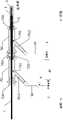
请参阅图5,为本发明其一较佳实施例中所述冷却套管的结构示意图。在该实施例中,所述光纤1、所述内管2及所述外管3为同轴布置;且所述光纤1的近端位于所述内管2的近端内,所述光纤1的远端远远位于所述内管2的远端之外,所述内管2的远端位于所述外管3远端之外。所述内管2的近端与所述外管3的近端之间连通形成所述回流腔6。所述内管2的远端与入口管路20连通,所述外管3的远端与出口管路30连通。Please refer to FIG. 5 , which is a schematic structural diagram of the cooling jacket in a preferred embodiment of the present invention. In this embodiment, the
进一步的,所述内管2优选为两端开口的管体结构。所述光纤1的近端既可以位于所述内管2的近端内又可以将所述光纤1的近端(一般设置有出光部,如图6所示)部分地伸出所述内管2的近端外,既将所述光纤1的近端部分留置于所述回流腔6内。所述外管3一般选为一端开口、另一端封闭的管件。所述外管3的近端即为所述外管3的封闭端。该封闭端一般设计成具有一定曲率或弧度的结构。优选地,所述外管3的封闭端为类似球体结构,以便于冷却介质(例如盐水)的方向回转,减少湍流产生。Further, the
再次参阅图5,所述入口管路20上布置有泵4和冷源,所述泵4优选为蠕动泵,所述冷源由冷却液箱5盛放。在所述冷却液箱5的内部或外部设置有加热恒温装置40。又或者,可以根据实际需要,在所述冷却液箱5的内部和外部均设置有加热恒温装置40,以便于把冷却液加热到人体适合的温度,防止冷却流体流经人体组织时刺激到组织。进一步的,所述出口管路30上布置有用于回收冷源的装置,一般可设置为废液池8。Referring to FIG. 5 again, a pump 4 and a cooling source are arranged on the
本发明还提供了一种光纤导管,以方便操作者的术中使用。如图6所示,为光纤导管结构示意图。所述光纤导管主要包含冷却套管以及密封设置于所述冷却套管远端外周的紧固组件7。所述冷却套管的形状等特性已于前文中进行了详细阐述,在此不做赘述。以下结合附图以及具体实施例来详细说明所述紧固组件7的具体结构特征。The invention also provides an optical fiber catheter, which is convenient for the operator to use in the operation. As shown in FIG. 6 , it is a schematic diagram of the structure of the optical fiber conduit. The fiber optic conduit mainly includes a cooling sleeve and a fastening component 7 sealingly disposed on the outer periphery of the distal end of the cooling sleeve. The shape and other characteristics of the cooling jacket have been described in detail above, and will not be repeated here. The specific structural features of the fastening assembly 7 will be described in detail below with reference to the accompanying drawings and specific embodiments.
大体地,所述紧固组件7包含管件本体701和管状连接件702。其中所述管件本体701的连接端口7011上设置有第一连接部;所述管件本体701上还另设有与外界连通的支管路7013;所述管状连接件702上设置有第二连接部;所述第二连接部与所述第一连接部相匹配,且经所述第二连接部和所述第一连接部的配合将所述管状连接件702与所述管件本体701固定连接。所述第一连接部和所述第二连接部之间的连接方式包含但不限于是螺 纹连接、法兰连接、焊接、卡箍连接、卡套式连接、卡压连接、热熔连接和卡固连接。在实际使用中,为方便产品的标准化生产,所述第一连接部和所述第二连接部之间的固定方式可以优选采用的螺纹结构,该螺接方式更加容易控制各零件之间的间隙,同时也便于拆卸调整。再者,螺纹连接使得密封件在装配过程中不会发生扭转,保证前后管件本体和管状连接件的同心度,避免了扭转引起的间隙不均,受力不均。进一步减小了漏水的风险,提高产品的良品率。Generally, the fastening assembly 7 includes a
请参阅图7,为紧固组件结构示意图。在本发明的其一较佳实施例中,所述紧固组件7包含管件本体701,所述管件本体701的两端用于连接的部位即为连接端口7011。所述连接端口7011的外周壁上设置有至少一个凸起连接部7012(即本发明所述的第一连接部)。所述管件本体701的一侧上另外设置有与外界连通的支管路7013。Please refer to FIG. 7 , which is a schematic diagram of the structure of the fastening assembly. In a preferred embodiment of the present invention, the fastening component 7 includes a pipe
请一并参阅图8A~图8F,为管状连接件的正六面视图。所述紧固组件7还包含管状连接件702。在靠近所述管状连接件702的两端部上分别开设有缺口连接槽7021(即本发明所述的第二连接部)。优选的,所述缺口连接槽7021为L型,该L型的所述缺口连接槽7021包含入口部70210和限位部70211。经所述缺口连接槽7021和所述凸起连接部7012的配合可实现所述管状连接件702与所述管件本体701的紧固连接。进一步的,所述管状连接件702的外表面还可以增设有若干加强筋7020,进而大大提高所述管状连接件702抗冲击性和耐用性。Please refer to FIG. 8A to FIG. 8F together, which are six-sided views of the tubular connector. The fastening assembly 7 also includes a
在本发明所述的一种光纤导管的其一较佳实施例中,所述内管2为两端开口的管体结构,所述外管3为一端开口、另一端封闭的管件。使用时,所述光纤1、所述内管2及所述外管3为同轴布置,且所述光纤1的近端部分地位于所述内管2的近端外,所述光纤1的远端远远位于所述内管2的远端之外,所述内管2的远端位于所述外管3远端之外。所述内管2的近端与所述外管3的近端之间连通形成所述回流腔6。In a preferred embodiment of the optical fiber conduit according to the present invention, the
另,在该实施例中,还配套设置有紧固组件7。所述紧固组件7包含至少2个管件本体701和1个所述管状连接件702,且所述管件本体701的外径与管状连接件702的内径相适配。所述管状连接件702卡固于2个所述管件本体701的对接处,即位于所述管状连接件702上的缺口连接槽7021和位于所述管件本体701上的凸起连接部7012相配合,便可以实现将个所述管状连接件702与所述管件本体701的卡固连接。In addition, in this embodiment, a fastening component 7 is also provided. The fastening assembly 7 includes at least two pipe
进一步的,所述冷却套管和所述紧固组件7之间还设置有密封件。所述密封件包含位于2个所述管件本体701的对接处还设置有衔接密封塞720、位于所述紧固组件7远端的所述连接端口7011内的远端密封塞710以及位于所述紧固组件7近端的所述连接端口7011内的近端密封塞730。其中,2个所述管件本体701的对接处优选设置于靠近所述内管2的远端位置处;即所述衔接密封塞720优先设置于2个管件本体701对接处的2个连接端口7011内。且,所述衔接密封塞720的中心孔内径与所述内管2外径相适配;所述远端密封塞710的中心孔与所述光纤1相适配,所述近端密封塞730的中心孔与所述外管3相适配。Further, a sealing member is also provided between the cooling jacket and the fastening assembly 7 . The sealing element includes a
进而,所述光纤1外壁、所述管件本体701(所指为靠近于冷却套管远端处的管件本体)内壁、所述远端密封塞710和所述衔接密封塞720便可以密封形成仅能够与所述内管2连通的进水型腔703。所述进水型腔703与所述入口管路20连通,所述入口管路20上布置有泵4和冷却液箱5;所述冷却液箱5的内部或外部还设置有加热恒温装置40,所述加热恒温装置40可用于把冷却介质加热到人体适合的温度,防止冷却流体流经人体组织 时刺激到组织。优选的,所述加热恒温装置40保证人体组织接触的冷却液温度保持在37.2℃附近,避免温差大引起的组织反映。相应的,所述内管2外壁、所述管件本体701(所指为靠近于冷却套管近端处的管件本体)外壁、所述衔接密封塞720和所述近端密封塞730可密封形成仅能够与所述外管3连通的出水型腔704。所述出水型腔704与所述出口管路30连通,所述出口管路30上布置有废液池8。Further, the outer wall of the
所述远端密封塞710、所述衔接密封塞720以及所述近端密封塞730的材料优选为软质的硅胶材料,通过材料的变形挤压完成密封效果,密封效果好。在保证密封性的同时,所述内管和所述外管的材料可以选用透光率更加好的玻璃材质,提高激光的效率。当然也可选择树脂材质,选择范围上更广,更易实现。The material of the
以上所述仅为本发明的实施例,并非因此限制本发明的专利范围,凡是利用本发明说明书及附图内容所作的等效结构或等效流程变换,或直接或间接运用在其他相关的技术领域,均同理包括在本发明的专利保护范围内。The above descriptions are only the embodiments of the present invention, and are not intended to limit the scope of the present invention. Any equivalent structure or equivalent process transformation made by using the contents of the description and drawings of the present invention, or directly or indirectly applied to other related technologies Fields are similarly included in the scope of patent protection of the present invention.
Claims (14)
Translated fromChinesePriority Applications (5)
| Application Number | Priority Date | Filing Date | Title |
|---|---|---|---|
| MX2023012067AMX2023012067A (en) | 2021-04-30 | 2022-04-26 | Cooling sleeve and optical fiber catheter having same. |
| EP22794898.1AEP4331518A4 (en) | 2021-04-30 | 2022-04-26 | COOLING SLEEVE AND FIBER OPTIC CATHETER EQUIPPED WITH SAME |
| BR112023022590ABR112023022590A2 (en) | 2021-04-30 | 2022-04-26 | COOLING SLEEVE AND FIBER OPTIC CATHETER |
| US18/287,076US20240197398A1 (en) | 2021-04-30 | 2022-04-26 | Cooling sleeve and optical fiber catheter having same |
| KR1020237038070AKR20230164180A (en) | 2021-04-30 | 2022-04-26 | Cooling sleeve and optical fiber conduit having the cooling sleeve |
Applications Claiming Priority (2)
| Application Number | Priority Date | Filing Date | Title |
|---|---|---|---|
| CN202110484230.XACN113081255A (en) | 2021-04-30 | 2021-04-30 | Cooling sleeve and optical fiber conduit with same |
| CN202110484230.X | 2021-04-30 |
Publications (1)
| Publication Number | Publication Date |
|---|---|
| WO2022228428A1true WO2022228428A1 (en) | 2022-11-03 |
Family
ID=76681147
Family Applications (1)
| Application Number | Title | Priority Date | Filing Date |
|---|---|---|---|
| PCT/CN2022/089280CeasedWO2022228428A1 (en) | 2021-04-30 | 2022-04-26 | Cooling sleeve and optical fiber catheter having same |
Country Status (7)
| Country | Link |
|---|---|
| US (1) | US20240197398A1 (en) |
| EP (1) | EP4331518A4 (en) |
| KR (1) | KR20230164180A (en) |
| CN (1) | CN113081255A (en) |
| BR (1) | BR112023022590A2 (en) |
| MX (1) | MX2023012067A (en) |
| WO (1) | WO2022228428A1 (en) |
Families Citing this family (4)
| Publication number | Priority date | Publication date | Assignee | Title |
|---|---|---|---|---|
| CN113081255A (en)* | 2021-04-30 | 2021-07-09 | 杭州佳量医疗科技有限公司 | Cooling sleeve and optical fiber conduit with same |
| CN114176770B (en)* | 2021-12-31 | 2023-01-24 | 华科精准(北京)医疗科技有限公司 | A cooling jacket and cooling device |
| CN116407271A (en)* | 2021-12-31 | 2023-07-11 | 华科精准(北京)医疗科技有限公司 | Laser ablation assembly and laser ablation system |
| CN115300099A (en)* | 2022-08-17 | 2022-11-08 | 北京化工大学 | Laser ablation cooler and method of making the same |
Citations (7)
| Publication number | Priority date | Publication date | Assignee | Title |
|---|---|---|---|---|
| US20030199860A1 (en)* | 2002-04-22 | 2003-10-23 | Loeb Marvin P. | Devices and methods for directed, interstitial ablation of tissue |
| US20060217693A1 (en)* | 2003-11-07 | 2006-09-28 | Biotex, Inc. | Cooled laser fiber for improved thermal therapy |
| CN104704311A (en)* | 2012-10-02 | 2015-06-10 | 三菱电机株式会社 | Double-tube heat exchanger and refrigerating cycle device |
| CN107087399A (en)* | 2014-10-22 | 2017-08-22 | 心脏起搏器股份公司 | Conveyer for leadless cardiac device |
| US20170319267A1 (en)* | 2016-05-05 | 2017-11-09 | Covidien Lp | Ablation instruments with a member having a triangular cross-section |
| CN113081255A (en)* | 2021-04-30 | 2021-07-09 | 杭州佳量医疗科技有限公司 | Cooling sleeve and optical fiber conduit with same |
| CN113180823A (en)* | 2021-04-30 | 2021-07-30 | 杭州佳量医疗科技有限公司 | Optical fiber conduit cooling system capable of removing fluid bubbles |
Family Cites Families (7)
| Publication number | Priority date | Publication date | Assignee | Title |
|---|---|---|---|---|
| US5827267A (en)* | 1992-02-18 | 1998-10-27 | Angeion Corporation | Cooled multi-fiber medical connector |
| US7127033B2 (en)* | 2004-02-28 | 2006-10-24 | Xoft, Inc. | Miniature x-ray tube cooling system |
| US10363092B2 (en)* | 2006-03-24 | 2019-07-30 | Neuwave Medical, Inc. | Transmission line with heat transfer ability |
| GB2457299B (en)* | 2008-02-09 | 2013-04-24 | Uk Investments Associates Llc | Microwave applicator |
| CN109009429A (en)* | 2018-06-19 | 2018-12-18 | 华科精准(北京)医疗科技有限公司 | device for laser ablation |
| CN111120755A (en)* | 2020-01-21 | 2020-05-08 | 成都奥森泰科技有限公司 | Pipe fitting quick-connection structure |
| CN215425064U (en)* | 2021-04-30 | 2022-01-07 | 杭州佳量医疗科技有限公司 | Cooling sleeve and optical fiber conduit with same |
- 2021
- 2021-04-30CNCN202110484230.XApatent/CN113081255A/enactivePending
- 2022
- 2022-04-26WOPCT/CN2022/089280patent/WO2022228428A1/ennot_activeCeased
- 2022-04-26MXMX2023012067Apatent/MX2023012067A/enunknown
- 2022-04-26USUS18/287,076patent/US20240197398A1/enactivePending
- 2022-04-26KRKR1020237038070Apatent/KR20230164180A/enactivePending
- 2022-04-26EPEP22794898.1Apatent/EP4331518A4/enactivePending
- 2022-04-26BRBR112023022590Apatent/BR112023022590A2/enunknown
Patent Citations (7)
| Publication number | Priority date | Publication date | Assignee | Title |
|---|---|---|---|---|
| US20030199860A1 (en)* | 2002-04-22 | 2003-10-23 | Loeb Marvin P. | Devices and methods for directed, interstitial ablation of tissue |
| US20060217693A1 (en)* | 2003-11-07 | 2006-09-28 | Biotex, Inc. | Cooled laser fiber for improved thermal therapy |
| CN104704311A (en)* | 2012-10-02 | 2015-06-10 | 三菱电机株式会社 | Double-tube heat exchanger and refrigerating cycle device |
| CN107087399A (en)* | 2014-10-22 | 2017-08-22 | 心脏起搏器股份公司 | Conveyer for leadless cardiac device |
| US20170319267A1 (en)* | 2016-05-05 | 2017-11-09 | Covidien Lp | Ablation instruments with a member having a triangular cross-section |
| CN113081255A (en)* | 2021-04-30 | 2021-07-09 | 杭州佳量医疗科技有限公司 | Cooling sleeve and optical fiber conduit with same |
| CN113180823A (en)* | 2021-04-30 | 2021-07-30 | 杭州佳量医疗科技有限公司 | Optical fiber conduit cooling system capable of removing fluid bubbles |
Non-Patent Citations (1)
| Title |
|---|
| See also references ofEP4331518A4* |
Also Published As
| Publication number | Publication date |
|---|---|
| MX2023012067A (en) | 2023-10-23 |
| KR20230164180A (en) | 2023-12-01 |
| EP4331518A1 (en) | 2024-03-06 |
| CN113081255A (en) | 2021-07-09 |
| BR112023022590A2 (en) | 2024-01-09 |
| US20240197398A1 (en) | 2024-06-20 |
| EP4331518A4 (en) | 2025-04-16 |
Similar Documents
| Publication | Publication Date | Title |
|---|---|---|
| WO2022228428A1 (en) | Cooling sleeve and optical fiber catheter having same | |
| CN101711705B (en) | Microwave ablation needle and microwave ablation therapeutic apparatus thereof | |
| CN115429415B (en) | Cold and hot ablation needle | |
| WO2012139085A4 (en) | System and method for cooling of a heated surgical instrument and/or surgical site and treating tissue | |
| CN209153957U (en) | Liquid nitrogen tumour ablation needle | |
| CN108523991B (en) | High-efficient refrigerated multi-functional microwave ablation needle | |
| CN103202728A (en) | Single microwave treatment needle with multiple acting sites | |
| EP4111993B1 (en) | Ablation device | |
| WO2023087671A1 (en) | Cryothermal ablation needle system | |
| CN215425064U (en) | Cooling sleeve and optical fiber conduit with same | |
| CN109259857A (en) | One kind semi-rigid penetration type water cooling Microwave Coagulation Therapy instrument under endoscope guidance | |
| CN209360883U (en) | Fission connection cryoablation needle and its needle assembly and backshank component | |
| CN102949235A (en) | Probe for tumor cold and hot combined treatment | |
| CN117958959A (en) | Water-cooling radio frequency electrode structure for nerve tissue ablation | |
| CN222804344U (en) | Connection structure for ablation catheter, ablation catheter and ablation system | |
| CN114176770B (en) | A cooling jacket and cooling device | |
| CN101912302A (en) | Hard microwave gall bladder mirror system | |
| CN115568936A (en) | Deep electrode | |
| CN200998312Y (en) | Temperature control microwave melting needle | |
| CN210354888U (en) | Cryoablation needle | |
| CN119606525B (en) | An internal circulation water-cooled electrode kit with adjustable temperature sensor position | |
| CN208481454U (en) | Flexible bipolar surgery instrument | |
| CN221431184U (en) | Ablation needle cooling assembly and ablation needle | |
| CN119014965B (en) | Electrode clamp cooling system and electrode clamp for clamp head rotating at any angle along the axis | |
| CN209332259U (en) | A kind of soft type water cooling Microwave Coagulation electrode of cup head half |
Legal Events
| Date | Code | Title | Description |
|---|---|---|---|
| 121 | Ep: the epo has been informed by wipo that ep was designated in this application | Ref document number:22794898 Country of ref document:EP Kind code of ref document:A1 | |
| WWE | Wipo information: entry into national phase | Ref document number:12023552636 Country of ref document:PH | |
| WWE | Wipo information: entry into national phase | Ref document number:MX/A/2023/012067 Country of ref document:MX | |
| WWE | Wipo information: entry into national phase | Ref document number:18287076 Country of ref document:US | |
| WWE | Wipo information: entry into national phase | Ref document number:2301006871 Country of ref document:TH | |
| ENP | Entry into the national phase | Ref document number:20237038070 Country of ref document:KR Kind code of ref document:A | |
| WWE | Wipo information: entry into national phase | Ref document number:1020237038070 Country of ref document:KR | |
| REG | Reference to national code | Ref country code:BR Ref legal event code:B01A Ref document number:112023022590 Country of ref document:BR | |
| WWE | Wipo information: entry into national phase | Ref document number:11202307707Q Country of ref document:SG Ref document number:2023128424 Country of ref document:RU Ref document number:2022794898 Country of ref document:EP | |
| ENP | Entry into the national phase | Ref document number:2022794898 Country of ref document:EP Effective date:20231130 | |
| NENP | Non-entry into the national phase | Ref country code:DE | |
| ENP | Entry into the national phase | Ref document number:112023022590 Country of ref document:BR Kind code of ref document:A2 Effective date:20231027 |