WO2022224322A1 - Data processing system, data provision system, event information generation device, data processing device, data processing method, and program - Google Patents
Data processing system, data provision system, event information generation device, data processing device, data processing method, and programDownload PDFInfo
- Publication number
- WO2022224322A1 WO2022224322A1PCT/JP2021/015930JP2021015930WWO2022224322A1WO 2022224322 A1WO2022224322 A1WO 2022224322A1JP 2021015930 WJP2021015930 WJP 2021015930WWO 2022224322 A1WO2022224322 A1WO 2022224322A1
- Authority
- WO
- WIPO (PCT)
- Prior art keywords
- data
- event information
- rdma
- data processing
- hub node
- Prior art date
- Legal status (The legal status is an assumption and is not a legal conclusion. Google has not performed a legal analysis and makes no representation as to the accuracy of the status listed.)
- Ceased
Links
Images


Classifications
- G—PHYSICS
- G06—COMPUTING OR CALCULATING; COUNTING
- G06F—ELECTRIC DIGITAL DATA PROCESSING
- G06F13/00—Interconnection of, or transfer of information or other signals between, memories, input/output devices or central processing units
- G06F13/14—Handling requests for interconnection or transfer
- G06F13/20—Handling requests for interconnection or transfer for access to input/output bus
- G06F13/28—Handling requests for interconnection or transfer for access to input/output bus using burst mode transfer, e.g. direct memory access DMA, cycle steal
- H—ELECTRICITY
- H04—ELECTRIC COMMUNICATION TECHNIQUE
- H04L—TRANSMISSION OF DIGITAL INFORMATION, e.g. TELEGRAPHIC COMMUNICATION
- H04L67/00—Network arrangements or protocols for supporting network services or applications
- H04L67/50—Network services
- G—PHYSICS
- G06—COMPUTING OR CALCULATING; COUNTING
- G06F—ELECTRIC DIGITAL DATA PROCESSING
- G06F15/00—Digital computers in general; Data processing equipment in general
- G06F15/16—Combinations of two or more digital computers each having at least an arithmetic unit, a program unit and a register, e.g. for a simultaneous processing of several programs
- G06F15/163—Interprocessor communication
- G06F15/173—Interprocessor communication using an interconnection network, e.g. matrix, shuffle, pyramid, star, snowflake
- G06F15/17306—Intercommunication techniques
- G06F15/17331—Distributed shared memory [DSM], e.g. remote direct memory access [RDMA]
- G—PHYSICS
- G06—COMPUTING OR CALCULATING; COUNTING
- G06F—ELECTRIC DIGITAL DATA PROCESSING
- G06F9/00—Arrangements for program control, e.g. control units
- G06F9/06—Arrangements for program control, e.g. control units using stored programs, i.e. using an internal store of processing equipment to receive or retain programs
- G06F9/46—Multiprogramming arrangements
- G06F9/54—Interprogram communication
- G06F9/542—Event management; Broadcasting; Multicasting; Notifications
- H—ELECTRICITY
- H04—ELECTRIC COMMUNICATION TECHNIQUE
- H04L—TRANSMISSION OF DIGITAL INFORMATION, e.g. TELEGRAPHIC COMMUNICATION
- H04L67/00—Network arrangements or protocols for supporting network services or applications
- H04L67/01—Protocols
- H04L67/10—Protocols in which an application is distributed across nodes in the network
- H04L67/1097—Protocols in which an application is distributed across nodes in the network for distributed storage of data in networks, e.g. transport arrangements for network file system [NFS], storage area networks [SAN] or network attached storage [NAS]
Definitions
- the present inventionrelates to technology for executing processing on data collected from multiple terminals.
- Non-Patent Document 1discloses a technique for analyzing surveillance camera images in real time and predicting congestion with high accuracy.
- the present inventionhas been made in view of the above problems, and it is an object of the present invention to provide a technology that makes it possible to easily provide a variety of arbitrary services using data collected from a plurality of terminals.
- a generating meansreceives data collected from a plurality of terminals, generates event information from the data, and transmits the generated event information to a broker device; an event information generation device comprising transmission means for transmitting data corresponding to the event information to a data hub node device corresponding to the event information generated by the generation means among the hub node devices; Acquisition means for acquiring event information corresponding to a specific service from the broker device; and acquisition of the data from a data hub node device storing data corresponding to the event information based on the event information acquired by the acquisition means.
- a data processing devicecomprising a processing means for executing processing using the data;
- a data processing systemis provided comprising:
- a technologyis provided that makes it possible to easily provide a variety of arbitrary services using data collected from multiple terminals.
- FIG. 1is a diagram for explaining an outline of RDMA;
- FIG. 1is a diagram for explaining an outline of RDMA;
- FIG. 1is a diagram for explaining an outline of RDMA;
- FIG. 1is a diagram for explaining an outline of RDMA;
- FIG. 1is a diagram for explaining an outline of RDMA;
- FIG. 1is a diagram for explaining an outline of RDMA;
- FIG. Itis a figure which shows the whole structural example of the communication system in 1st Embodiment. It is a figure for demonstrating an implementation image. It is a figure for explaining a problem.
- FIG. 4is a diagram for explaining an implementation model;
- FIG. 4is a diagram for explaining an implementation model;
- FIG. 4is a diagram for explaining an implementation model;
- FIG. 4is a diagram for explaining an implementation model;
- FIG. 4is a diagram for explaining an implementation model;
- FIG. 4is a diagram for explaining an implementation model;
- FIG. 4is
- FIG. 1is a configuration diagram of an edge node device;
- FIG. 1is a configuration diagram of a message broker device;
- FIG. 1is a configuration diagram of a data hub node device;
- FIG. 1is a configuration diagram of an AI application node device;
- FIG.It is a figure for demonstrating the operation example of the data processing system in 2nd Embodiment.
- RDMAuses hardware equivalent to NIC such as Ethernet (referred to as RDMA-NIC in this embodiment).
- the RDMA-NIC on the transmitting sidereads data by DMA from a memory area reserved in advance and transfers it to the RDMA-NIC on the receiving side. Similarly, the RDMA-NIC on the receiving side writes the received data to a memory area reserved in advance by DMA.
- Thisenables zero-copy communication between user space applications in different nodes.
- the network protocolis implemented in the RDMA-NIC (hardware), which reduces the consumption of OS layer CPU resources in the communication device installed in the node and realizes low-latency communication.
- QPis a virtual interface provided by RDMA-NIC and consists of a pair of Send Queue (SQ) and Receive Queue (RQ).
- SQSend Queue
- RQReceive Queue
- the SQ and RQstore data related to data transmission and data reception, respectively. This includes information such as the address of the memory area where the data is stored and its length. A virtual memory address or a physical memory address is used as the memory area.
- the memory area to be accessed by the RDMA-NICis registered in the OS as a Memory Region. Also, by creating a conversion table between virtual memory addresses and physical memory addresses when registering the Memory region and passing this to the RDMA-NIC, the RDMA-NIC recognizes part of the virtual memory address space of the user program (APP). become able to.
- the RDMA-NICcan refer to this conversion table during transmission and reception to determine the physical memory address to be accessed. Therefore, it is possible to transfer data while minimizing the use of the CPU of the OS layer in the communication device installed in the node.
- a physical memory addressmay be used as the memory area.
- a memory region using physical memory addressesis called a PA-MR (Physical Address Memory Region).
- PA-MRPhysical Address Memory Region
- a transmission request/reception request including information on the physical memory address of the memory area for storing data and its lengthis stored in SQ/RQ, and based on the transmission request/reception request, physical memory address can be accessed.
- a transport layer communication model in RDMA between the Local node and the Remote nodewill be described with reference to FIG.
- a QPQuadeue Pair
- QPis a set of SQ (Send Queue) and RQ (Receive Queue).
- the communication unit of RDMAis a communication request called WR (Work Request), which is loaded into SQ/RQ in units of WQE (Work Queue Element).
- This WQ stacking operationis performed by an instruction from the user program (APP shown in FIG. 1).
- Transmission/reception operations for communication requestsare performed by the RDMA-NIC asynchronously with the operation of loading WQs.
- Send WRthe memory area of the data to be sent is specified in WQE and loaded in SQ.
- Receive WRspecify the memory area where you want to receive data in WQE and load it in RQ.
- WQEscan be stacked in FIFO (First-In-First-Out) by the number of queue depths of SQ/RQ.
- Service types in RDMAare roughly divided into four service types: Reliable Connection (RC), Reliable Datagram (RD), Unreliable Connection (UC), and Unreliable Datagram (UD), depending on the classification of Reliable/Unreliable and Connection/Datagram. .
- RCReliable Connection
- RDReliable Datagram
- UCUnreliable Connection
- UDUnreliable Datagram
- RCguarantees the order and reachability of messages by means of acknowledgment of communication success/abnormality and retransmission by ACK/NAK. It is also a Connection type, and performs one-to-one communication between Local-Remote QPs.
- UDdoes not have a mechanism for acknowledgment or retransmission, unlike RC, many-to-many communication such as transmission to multiple QPs and reception from multiple QPs is possible by specifying a destination for each communication.
- Operation types in RDMAare roughly divided into four operation types: SEND, RDMA WRITE (with Immediate), RDMA READ, and ATOMIC Operations. All of these can be used in RC, and only SEND can be used in UD. Even for the same operation type, the way WQEs and CQEs are stacked differs depending on the service type.
- Any service type and operation typecan be used in the RDMA communication in the present embodiment (first embodiment, second embodiment). Each operation type is described below.
- FIG. 3shows an outline of the operation of the SEND operation method (RC).
- the SEND operation method (RC)is a basic transmission/reception model of RDMA, in which the local side transmits data to the remote side.
- the WQE of RQis extracted from the beginning and stored in the specified memory area.
- CQEis added to CQ corresponding to RQ, and ACK is returned to the Local side.
- the CQEis loaded and the WQE of the SQ is released.
- FIG. 4shows an operational overview of the SEND mode of operation (UD).
- the SEND operation method (UD)is a method that does not perform an acknowledgment unlike the SEND of RC.
- the Local sideprepares SQ and the Remote side prepares RQ, and WQE is loaded respectively.
- the Local sidetransmits data in SEND Only.
- CQEis added to CQ corresponding to SQ.
- CQEis added to the CQ corresponding to the RQ.
- FIG. 5shows an operational overview of the RDMA WRITE operation scheme (RC).
- the RDMA WRITE operation method (RC)is a method in which the Local side transmits data to the Remote side, but differs from SEND in that data is directly transferred to the Remote memory area.
- the local sideprepares SQ and loads WQE. At this time, in addition to the memory area of the data to be transmitted, the memory area on the remote side to be written is also specified in the WQE.
- the remote sidereserves a memory region for RDMA, but there is no need to add WQE to RQ.
- the local sideWhen communication is ready, the local side sends data using RDMA Write. Data is written directly to the memory area on the remote side. If reception is successful on the Remote side, ACK is returned to the Local side. When the Local side receives the ACK, the CQE is loaded and the WQE of the SQ is released.
- FIG. 6shows an operational overview of the RDMA WRITE w/Imm mode of operation (RC).
- the RDMA WRITE described with reference to FIG. 5has a problem that the remote side cannot detect a change in the memory area when receiving data.
- RQ and WQEare set on the remote side, and CQE is waited for when RDMA WRITE reception is successful.
- FIG. 7shows an overview of the RDMA READ operation scheme (RC).
- the RDMA READ operation method (RC)is a method of pulling data from the Remote side to the Local side.
- the local sideprepares SQ and loads WQE.
- the WQEdesignates a memory area from which data is to be received.
- the memory area on the remote side from which reading is to be performedis also specified.
- the remote sidereserves a memory region for RDMA, but there is no need to add WQE to RQ.
- the local sideWhen communication is ready, the local side requests data reading with RDMA Read Request. When the Remote side receives this, it directly sends the data in the Remote side memory area to the set Local side memory area as an RDMA Read Response.
- the RDMA Read Response packetcontains an ACK extension header, and when the Local side receives this ACK, the CQE is loaded and the SQ WQE is released.
- FIG. 8shows an overall configuration diagram of a communication system according to the first embodiment.
- this communication systemincludes a local aggregation node (LA) that connects a plurality of terminals, a regional edge node (RE) that connects a plurality of local aggregation nodes (LA), and an application node (AP).
- LAlocal aggregation node
- REregional edge node
- APapplication node
- the terminalis a camera.
- Regional edge nodes(RE) are assumed to be installed in each region such as Tokyo and Osaka.
- a plurality of local aggregation nodes (LA)exist for each region, and each local aggregation node (LA) accommodates a plurality of terminals (eg, cameras).
- Each nodeis connected by, for example, an optical network.
- the image data collected from the cameraswill be analyzed.
- the content of the analysisfor example, the number of people in the area is counted, which is useful for congestion avoidance, evacuation guidance, and the like.
- the number of people including their attributesit is possible to perform demand forecasting, optimization of inventory/clerk placement, analysis of the effects of events and the like, planning of events and advertisements, and the like. Also, by detecting a person who behaves suspiciously, it can be used for crime prevention.
- Fig. 9assume a block of 500m x 500m with streets 50m wide and in a grid pattern, and install cameras every 10m with the following specifications.
- This datais input to, for example, one local aggregation node (LA) shown in FIG.
- FIG. 10shows an image of the data flow from the camera to the application node (AP) via the local aggregation node (LA) and the regional edge node (RE).
- APapplication node
- LAlocal aggregation node
- REregional edge node
- 60 Mbps TCP data transferis simultaneously executed for 1000 cameras.
- the OS layerautonomously performs flow control and buffers data without optimizing communication according to the size of data to be transferred and the update rate.
- RDMAwhich enables direct data communication between memories, is used as a communication method between LA and RE. That is, each of the local aggregation node (LA) and the regional edge node (RE) is provided with an information communication device with an RDMA-NIC. In the information communication device, an RDMA virtual memory area is secured (registered) according to the size of collected data, and a network band is allocated according to the size and update rate of this virtual memory area. This allocation can be done dynamically. Methods for dynamically allocating network bandwidth include, for example, the following methods. In addition, the following method is an example, and it is good also as using methods other than the following methods.
- the number of optical wavelengthsis dynamically changed.
- MPLS-TE and RSVP-TEperform bandwidth control using traffic engineering functions.
- the forwarding nodeperforms bandwidth control using a traffic shaper, etc.
- FIG. 11shows an example of communication using RDMA between the local aggregation node (LA) and the regional edge node (RE) under the assumption of the camera arrangement described above.
- FIG. 11shows the memory used by RDMA at each of the local aggregation nodes (LA) and the regional edge nodes (RE).
- the total rate of 60 Gbpsis 1 frame of 500 kB x 1000 cameras x 15 FPS, and 1000 cameras fit into 500 MB. Therefore, a memory area of 500 MB is secured in the information communication device on the local (ground) side. However, on the local side, since it is necessary to write the image data of the next frame into the memory during data transfer, two areas are generated in total, one for writing to the memory and the other for transferring the memory. That is, as shown in FIG. 11, two memory areas are generated: a memory area of 500 MB as the G1 area and a memory area of 500 MB as the G2 area. Each memory area is updated at 15 Hz. At least two or more memory areas should be secured.
- a network band(60 Gbps + ⁇ ) is allocated according to the total data rate of 60 Gbps. It should be noted that ⁇ expresses allocation of bandwidth with a margin, and may be allocated to include the header overhead of the encapsulating protocol and other control messages, for example, about 10%.
- the optical pathmay be shared by performing label multiplexing or the like.
- FIG. 12is a diagram showing the functional configuration of the information communication device 100 on the LA side and the information communication device 200 on the RE side.
- the information communication device 100 and the information communication device 200are connected by an optical network 300 .
- the information communication device 100 on the LA sidehas a data transmission section 110, a control section 120, and an RDMA communication section .
- the data transmission unit 110 and the control unit 120are functional units implemented by CPU, FPGA, physical memory, user programs, and the like.
- the RDMA communication unit 130corresponds to an RDMA-NIC.
- the data transmission unit 110receives data from the terminal side, stores the data in the physical memory, and issues a transmission command to the RDMA communication unit 130 . Issuing a transmission command corresponds to accumulating a transmission request in the transmission queue in the RDMA communication unit 130 .
- the control unit 120grasps the size and update rate of data to be transferred by monitoring the data transmission unit 110 or by acquiring information on the terminal side. Based on the size of the data, the control unit 120 determines the size of the memory area used by the RDMA communication unit 130 (referred to as the update size because the update is performed in units of this size) to secure the memory area. Based on the size and update rate of , the bandwidth of the network path for performing data communication by RDMA communication between LA and RE is determined, and the bandwidth is secured.
- control unit 120includes determination means operating in the first layer for determining the update size of the memory area used to hold the data based on information on data transmitted from a plurality of terminals; setting means for setting a bandwidth of a second layer network path necessary for communication with a receiving side based on the update size and the data update rate. Since the layer for size determination processing and the layer for processing related to RDMA communication are different, they are called the first layer and the second layer.
- the information grasped by the control unit 120 on the LA side(data size, update rate, etc.) is notified to the control unit 220 of the information communication device 200 on the RE side, and the control unit 220 sends the RDMA communication unit 230 a memory Perform processing such as securing the area.
- the control unit 120grasps the number of terminals and the amount of data transmitted at the update rate from each terminal based on the received data. can be done. Further, as shown in FIG. 13, an operation system 250 is provided, and each of the control unit 120 and the control unit 220 receives information from the operation system 250, such as the number of terminals, and the update rate and data size of data transmitted from each terminal. to know the size and update rate of the data.
- the RE-side information communication device 200has a data reception unit 210, a control unit 220, and an RDMA communication unit 230.
- the data receiving unit 210 and the control unit 220are functional units realized by CPU, XPU, physical memory, user programs, and the like.
- the RDMA communication unit 230corresponds to an RDMA-NIC.
- various processor unitssuch as GPU are generically called XPU.
- the data receiving unit 210receives data from the LA side via the RDMA communication unit 230, stores the data in the physical memory, and executes data processing by, for example, the XPU.
- the data receiving unit 210may acquire data from the LA side and store it in the physical memory by executing the RDMA READ operation. This makes it possible to cope with the case where the LA side is relatively weak due to the equipment configuration.
- data receptionmay be performed by either the LA side or the RE side.
- the control unit 220grasps the data size, update rate, etc. Based on the grasped information, the memory area used by the RDMA communication unit 230 and network bandwidth. In addition, the control unit 220 calculates the time to hold data in the RE based on the data processing time, etc., and secures the number of memory areas corresponding to the data holding time.
- an information communication device 100is provided on the LA side, and an information communication device 200 is provided on the RE side.
- one LAis connected to the RE in the example of FIG. 14, this is an example, and the RE can connect multiple LAs.
- the information communication device 100 in LAmay be called a proxy server. This is because the information communication device 100 has a function that enables RDMA communication on the network even if the terminal (camera, etc.) does not support RDMA.
- An optical packet transponder 14is connected to the information communication device 100 and an optical packet transponder 26 is connected to the information communication device 200 .
- An optical network 300connects between the optical packet transponder 14 and the optical packet transponder 26 .
- the optical packet transponder 14 on the LA sideconverts the electrical signal output from the RDMA-NIC 12 of the information communication device 100 into an optical signal and transmits the optical signal.
- the optical packet transponder 26 on the RE sideconverts the optical signal received from the optical network 300 into an electrical signal and sends the electrical signal to the RDMA-NIC 24 of the information communication device 200 .
- 80 camerasare connected to the information communication device 100 on the LA side via a LAN. It should be noted that, even with TCP/IP, data transfer from the camera is assumed to be communication over several hundred meters at most, so it is assumed that high-speed data transfer is possible.
- FIG. 14shows a configuration close to a physical implementation for each of the information communication device 100 and the information communication device 200 in order to facilitate explanation of the state of the memory area.
- the information communication device 100includes a control unit 120, a smart NIC 11, and an RDMA-NIC 12, and the smart NIC 11 and RDMA-NIC 12 are connected by a CI (Component Interconnect) 13.
- CIComponent Interconnect
- the smart NIC 11has an FPGA and physical memory.
- the FPGAhas a TCP service function, receives data output from the cameras 1 to 80, and stores the data in a memory area secured by the control unit 120 in the physical memory.
- the RDMA-NIC 12is hardware that performs RDMA communication as described above.
- FIG. 14shows a memory region of virtual memory, which is a mapping of physical memory.
- a memory area to be accessed by the RDMA-NIC 12 in the information communication device 100is secured by the control unit 120 specifying a virtual memory address corresponding to the memory area. Since the virtual memory is a mapping of the physical memory, the memory area secured by the control unit 120 is both a memory area in the virtual memory and a memory area in the physical memory.
- the information communication device 200includes a control unit 220, an XPU card 21, a CPU card 22, a central memory card 23, and an RDAM-NIC 24.
- the XPU card 21, the CPU card 22, the central memory card 23, and the RDAM-NIC 24are , CI25.
- the XPU card 21includes, for example, an XPU that performs image analysis and a physical memory.
- the CPU card 22includes a CPU and a physical memory for performing analysis result utilization processing and the like.
- the central memory card 23comprises physical memory.
- the central memory card 23may be a so-called high-speed storage on the motherboard in PC architecture, or an independent storage such as NVME Array. By DMA-transferring data from the RDMA-NIC 24 to the physical memory on the central memory card 23 (motherboard) without intervening the CPU, the physical memory can be used without increasing the CPU load. Also, a plurality of central memory cards may be configured in a RAID configuration for high performance and HA.
- NVME Arrayas the central memory card 23, it may be connected at high speed with a computing system functional unit via an interconnect.
- the RDMA-NIC 24is hardware that performs RDMA communication as described above.
- FIG. 14shows a memory region of virtual memory, which is a mapping of physical memory.
- a memory area to be accessed by the RDMA-NIC 12is secured in the information communication device 200 by specifying a virtual memory address corresponding to the memory area by the control unit 220 . Since the virtual memory is a mapping of the physical memory, the memory area secured by the control unit 220 is both a memory area in the virtual memory and a memory area in the physical memory.
- the control unit 120 in the information communication device 100 on the LA sidecontrols the memory area to be accessed by the RDMA-NIC 12 and the space between LA and RE. If the number of cameras decreases, such as increasing the connection bandwidth at the same rate, the memory area to be accessed by the RDMA-NIC 12, and LA and RE Increase or decrease the connection bandwidth between Information on the amount of memory area and connection bandwidth determined by control unit 120 is also notified to control unit 220 in information communication device 200 on the RE side. In the information communication device 200, the memory area to be accessed by the RDMA-NIC 24 and the connection band between LA and RE are increased or decreased.
- control unit 120 in the information communication device 100 on the LA side and the control unit 220 in the information communication device 200 on the RE sidecontrol the transfer data generation rate, that is, the number of cameras serving as image data acquisition terminals (data "source”).
- the memory area/connection bandmay be increased or decreased according to changes such as increase or decrease.
- the specified memory areamay be allocated deterministically, or may be dynamically allocated from among free memory areas. Also, the allocated area can be increased as needed each time.
- each memory areais managed in three states: waiting for transfer to RE or transferring, writing in progress, and newly writable.
- LAwhen the area in the writable state is newly reduced, this area is increased, and RE is also requested to increase the memory area.
- a memory area holding data being transferred from LA to REa memory area holding data being received by LA, and a state holding data being processed by RE. memory area is shown.
- the control unit 120performs the above memory allocation control and memory status management. However, this is an example, and means other than the control unit 120 (eg, smart NIC 11, RDMA-NIC 12, an external device, etc.) may perform this. An operation example of the communication system shown in FIG. 14 will be described below.
- each cameraencodes each frame at a maximum of 500 kB.
- the frame rateis 15FPS.
- Information that 80 cameras are connected, each camera encodes each frame at a maximum of 500 kB, and outputs image data at 15 FPSis notified to the controller 120 on the LA side from the camera itself or the operation system. Note that the control unit 120 may estimate the information from the received data.
- the control unit 120divides two memory areas each having a size of 500 kB ⁇ 80 units as memory areas to be accessed by the RDMA-NIC 12 (that is, memory areas of the physical memory of the smart NIC 11). In addition to securing, the secured memory area is divided into areas of 500 kB each. Note that 500 kB ⁇ 80 units is the update size.
- the area of "000"indicates 20 areas of addresses 0 to 19, each area having a size of 500 kB. The same applies to other areas. In other words, 80 500 kB areas corresponding to the number of cameras are secured in each memory area.
- each camerais assigned two areas. For example, camera 1 is assigned areas with addresses 0 and 80, and camera 2 is assigned areas with addresses 1 and 81. FIG.
- the control unit 120 and the control unit 220allocate a band of 60 Mbps ⁇ 80 units+ ⁇ to the RDMA-NIC pair between LA and RE.
- ⁇ (beta)expresses allocation of bandwidth with a margin, and may be allocated to include header overhead by the encapsulating protocol and other control messages, for example, about 10%.
- the central memory (the physical memory of the central memory card 23) in the information communication device 200 of the REholds data for 5 frames of images. Therefore, the control unit 210 secures five memory areas (update size) each having a size of 500 kB ⁇ 80 units, and divides the secured memory area into areas of 500 kB each.
- the area of "000"indicates 20 areas of addresses 0 to 19, each area having a size of 500 kB. The same applies to other areas.
- camera 1is assigned areas 0, 80, 160, 240, and 320
- camera 2is assigned areas 1, 81, 161, 241, and 321. to assign regions to each camera.
- the copy destination areaWhen copying memory from LA to RE, the copy destination area will be rotated. Such rotation may be realized, for example, by the control unit 120 on the transmission side specifying the copy destination area when accumulating the transmission request in the transmission queue, or the RDMA-NIC 12 itself may implement the rotation. may be controlled. In addition, when the RE-side control unit 220 loads a receive request specifying a memory area into the receive queue using the RDMA READ operation, it may be realized by specifying the copy destination area, or the RDMA-NIC 24 itself may control rotation.
- the TCP service in the smart NIC 11alternately writes the image data received from each camera to the area of the camera. For example, the image data of frame 1 received from camera 1 is written in the 0 address area, and the image data of frame 2 received from camera 1 is written in the 80 area. While the image data of frame 2 is written to the area of address 80, the image data of area of address 0 is read by the RDMA-NIC 12 and transferred to the RE side. Therefore, the image data of the frame 3 received from the camera 1 is written in the 0 address area. Such processing is performed for each camera.
- the data transferred from the RDMA-NIC 12 to the RE sideis stored by the RDMA-NIC 24 on the RE side in an area in the central memory corresponding to the camera that sent the data.
- the area from "080" to "140"indicates that the data is being transferred from LA-RE, that is, the data being written.
- each programaccesses or copies the data in the central memory card by DMA.
- the data "000" that has already been stored before the data being transferredis stored in the physical memory of the XPU by DMA transfer and processed by the XPU.
- the virtual memory address and the physical memory address in the RDMA-NIC 24 of the REneed only be linked in a one-to-one relationship, and the designated memory area need not be fixed.
- the physical memory addresses designated as virtual memory addressesmay change over time.
- This controlmay be performed by the RDMA-NIC 24 or by the control unit 220 .
- the relationship between virtual memory addresses and physical memory devicesis set so that the load on the physical devices is even. may be adjusted. For example, when the load increases, the correspondence destination may be changed to another physical device. This control may be performed by the RDMA-NIC 24 or by the control unit 220 .
- the reliability of the physical devicemay be improved by changing the correspondence destination to another physical device.
- This controlmay be performed by the RDMA-NIC 24 or by the control unit 220 .
- N copiesmay be implemented to increase the reliability of data. That is, multiple physical memory addresses may be mapped to one virtual memory address, and the values received by the RDMA-NIC 24 for the virtual memory address may be written to the multiple physical addresses. At this time, instead of writing the same value to a plurality of physical addresses, the result of an operation such as RSE (Reed Solomon Erasure) may be written. Also, in the conversion process for increasing the reliability of data, a function that can ensure security by secret sharing may be used.
- N-copy by optical multicastmay be performed for high reliability of data. That is, high reliability may be realized by simultaneously copying from one LA to a plurality of REs by optical multicast.
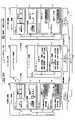
- FIG. 15shows a configuration example of a data processing system according to the second embodiment.
- the second embodimentis based on the technology of the first embodiment, and FIG. 15 describes in more detail the configuration from the regional edge node (RE) to the application node (AP) in the system configuration shown in FIG. Equivalent to things.
- an AI applicationis assumed as an application that operates on an application node, so an AI application node is described as a specific example of the application node.
- the regional edge nodes (RE) and the data hub nodes (DH), and the data hub nodes (DH) and the AI application nodes (AP)are respectively connected by optical networks, for example.
- the message broker node (MB) and the data hub node (DH)may collectively be configured as one node (one device).
- the second embodimentis a case in which the memory allocation is fixed in advance according to the characteristics of the use case, thereby reducing the intervention of the CPU as much as possible and executing the LA ⁇ -> RE transfer & AI service with a low load.
- RDMAis used for communication between the regional edge node (RE) and the data hub node (DH) and between the data hub node (DH) and the AI application node (AP)
- RDMAAlthough it is not essential to use RDMA, by using RDMA together, it is possible to reduce the communication delay between the regional edge node (RE) and the AI application node (AP), and at each node This reduces the load on the nodes, which in turn improves the node aggregation effect, and ultimately reduces the power consumption of the entire system. A similar effect can be expected even if a communication method other than RDMA is used.
- Any communication methodmay be used for communication between the regional edge node (RE) and the message broker node (MB) and between the message broker node (MB) and the AI application node (AP).
- REregional edge node
- MBmessage broker node
- APAI application node
- RDMAmay be used, or general IP communication (such as the Internet) may be used.
- regional edge nodesare installed in Tokyo, Osaka, Nagoya, Fukuoka, and Yokohama.
- Message broker nodesMB
- data hub nodesDH
- a “topic”may be called an “event”.
- AI application nodesare scattered due to the convenience of application providers.
- “suspicious person detection”, “accident rate prediction”, “congestion mitigation”, “demand prediction/inventory optimization”, “micro traffic operation optimization”, “planogram optimization”, and “campaign A plurality of AI application nodes (APs)are arranged for making proposals, etc.
- each AI application node(AP)
- APAI application node
- a plurality of terminalsare connected via a LAN under the local aggregation node (LA), as in the first embodiment.
- the terminalis, for example, a camera (smart camera).
- a smart camerais an example of a device that collects so-called sensor information. It is equipped with an image sensor and DSP, and has the function of encoding and compressing camera images and transmitting them to a LAN.
- a terminal provided under the local aggregation node (LA)may be any device as long as it is a sensor device that collects sensor information.
- ⁇ Device configuration example>An example of the functional configuration of the device arranged in each node will be described below.
- the configuration of the information communication device 100 placed in LAis the same as the configuration of the information communication device 100 shown in FIG. 12 (and FIG. 13) of the first embodiment.
- FIG. 16shows a configuration example of an edge node device 400 provided in a regional edge node (RE).
- the functions of the edge node device 400are basically the same as the functions of the RE-side information communication device 200 shown in FIG. 12 (FIG. 13) of the first embodiment. Since transmission and transmission of data to the data hub node are performed, the configuration shown in FIG. 16 includes functions related to this point. Note that the edge node device 400 may be called an event information generation device.
- the edge node device 400has a data transmission/reception unit 410, a control unit 440, an RDMA communication unit 430, and an event information generation unit 420.
- the data transmission/reception unit 410, the control unit 440, and the event information generation unit 420are functional units implemented by a CPU, XPU, physical memory, user programs (applications), and the like.
- the RDMA communication unit 430corresponds to the RDMA-NIC.
- the data transmission/reception unit 410receives data transmitted from the LA side via the RDMA communication unit 430 and stores the data in the physical memory. Also, the data transmission/reception unit 410 uses the RDMA communication unit 430 to transmit data to the data hub node device corresponding to the event information.
- the dataWhen sending data to the data hub node device, the data is sent to the data hub node device corresponding to the event information (topic) corresponding to the data to be sent. Also, as the address of the memory area of the data storage destination in the data hub node device, the address of the memory area corresponding to the region to which the edge node device 400 of the data transmission source belongs is designated.
- the event information generation unit 420performs data analysis by XPU or the like on the data received from the LA side, generates event information based on the analysis result, and sends the event information to the message broker device corresponding to the event information. to send.
- the event informationincludes information indicating a topic, analysis result information, and information (such as an address) identifying a storage destination of the event information (a data hub node device and its memory area).
- the event information generation unit 420includes generation means for receiving data collected from a plurality of terminals, generating event information from the data, and transmitting the generated event information to the broker device.
- the data transmission/reception unit 410 and the RDMA communication unit 430correspond to the event information generated by the generating means for the data hub node device corresponding to the event information generated by the generation means, among the plurality of data hub node devices that differ for each event information. and transmission means for transmitting data to be transmitted.
- the control unit 440grasps the data size and update rate based on the information received from the LA-side control unit 120 or the operation system 250, and based on the data size and update rate, the RDMA communication unit 430 uses Secure the memory area to be used and secure the network bandwidth. In addition, the control unit 440 calculates the time for holding data in the RE based on the data processing time, etc., and secures the number of memory areas corresponding to the data holding time.
- FIG. 17shows an example of the functional configuration of the message broker device 500 provided in the message broker node (MB).
- the message broker device 500may also be called a broker device.
- the message broker device 500 in the second embodimentis assumed to have broker functions in the Publisher/Subscriber model.
- the message broker device 500has a message receiving unit 510, a message storage unit 520, and a message delivery unit 530.
- the message receiving unit 510receives a message (specifically, event information) on a certain topic from the distributor (RE) and stores the received message in the message storage unit 520 .
- the message distribution unit 530transmits a topic message to a subscriber (here, an AI application node) who subscribes to the topic.
- FIG. 18shows a functional configuration example of the data hub node device 600 provided in the data hub node (DH).
- the data hub node device 600has a data transmission/reception section 610, a control section 630, and an RDMA communication section 620.
- the data transmission/reception unit 610 and the control unit 630are functional units realized by a CPU, physical memory, user programs (applications), and the like.
- RDMA communication unit 620corresponds to RDMA-NIC.
- the data transmission/reception unit 610receives data from the edge node device 400 via the RDMA communication unit 620 and stores the data in the physical memory. Further, the data transmission/reception unit 610 issues a transmission command to the RDMA communication unit 620 to transmit data to the AI application node device 700, and performs data transmission by RDMA.
- the control unit 630secures a memory area used by the RDMA communication unit 620, secures a network band, and the like.
- FIG. 19shows a functional configuration example of an AI application node device 700 provided in an AI application node (AP).
- the AI application node device 700has an event information processing section 710 , a data processing section 720 , an RDMA communication section 730 and a control section 740 .
- the event information processing unit 710, the data processing unit 720, and the control unit 740are functional units realized by the XPU, CPU, physical memory, user programs (applications), and the like.
- RDMA communication unit 730corresponds to RDMA-NIC.
- the AI application node device 700may be called a data processing device.
- the event information processing unit 710acquires event information from the message broker device 500 and processes the event information. That is, the event information processing unit 710 includes acquisition means for acquiring event information corresponding to a specific service from the message broker device.
- the data processing unit 720receives data from the data hub node device 600 via the RDMA communication unit 730, stores the data in the physical memory, and executes processing by the XPU or the like.
- the control unit 740secures a memory area used by the RDMA communication unit 730, secures a network band, and the like.
- the data processing unit 720 and the RDMA communication unit 730acquire the data from the data hub node device that stores the data corresponding to the event information based on the event information acquired by the acquisition unit, and use the data. It includes processing means for performing processing.
- a pool of processors that constitute the data processing unit 720may be provided, and the pool or part of the pool may be allocated to the user.
- a plurality of XPUsare provided, and the plurality of XPUs are defined as an XPU pool.
- the XPU poolis divided into a plurality of pools and the divided pools are assigned to each user.
- a plurality of XPU poolscomprising a plurality of XPUs may be provided. For example, if you have XPU pool 1, XPU pool 2, and XPU pool 3, you can assign XPU pool 1 to user A, XPU pool 2 to user B, and XPU pool 3 to user C. can.
- the data to be processedis sent to the AI application node device 700 from the data collection system prepared by the user (or the data hub node device 600 of this embodiment).
- the AI application node device 700data of the user is transferred to the XPU pool assigned to the user, and calculation processing is performed on the data of the user.
- the analysis object datais image data (video data) transmitted from a camera.
- the configuration including the edge node device 400 (event information generating device) and the data hub node device 600constitutes a platform that provides data to the AI application node device 700 (data processing device).
- a platform having the edge node device 400 and the data hub node device 600may be called a data providing system.
- a device that acquires data from this data providing system and processes the datais not limited to the AI application node device 700 .
- an application server prepared by the usermay acquire data from the data providing system and process the data.
- the event information generation unit 420 of the edge node device 400detects an event from the object detection information obtained by analyzing the image data received from the LA, and generates event information regarding the event. In S102, the event information generation unit 420 transmits the generated event information to the message broker device 500 of the topic related to the event information.
- the event information generation unit 420when the event information generation unit 420 obtains a newly recognized human image as object detection information, it generates event information having a topic of "counting people”. Also, for example, when the event information generation unit 420 obtains a human image detected in a specific monitoring area as the object detection information, it generates event information having a topic of “crime prevention”. Further, for example, when the event information generation unit 420 obtains a human image detected in a store or shop area as the object detection information, it generates event information having a topic of “customer behavior analysis”.
- the event informationmay include information obtained through analysis along with the topic.
- event information having a topic of "counting people”may include the result of counting people.
- the data transmission/reception unit 410transfers the object image data attached to the event information to the data hub node device 600 corresponding to the event information via the RDMA communication unit 430 (S103).
- the event information generator 420includes the virtual memory address of the transfer destination data hub node device 600 in the event information transmitted in S102.
- the event information processing unit 710 of the AI application node device 700acquires event information from the event broker device 500 in S104.
- This event informationis, for example, event information corresponding to a specific service provided by the AI application node device 700 .
- the event information processing section 710determines to process the event and requests the data processing section 720 to process the event. For example, the event information processing unit 710 compares the previous event information and the current event information, and determines to process the event when there is a change in the information.
- the data processing unit 720uses the address information included in the event information to acquire the image data corresponding to the event information from the data hub node device 600. Then, the process is executed (S105, S106).
- a connection configuration example between the local aggregation node (LA) and the regional edge node (RE)is the same as the connection configuration example in the first embodiment, as shown in FIG. Its operation is also basically the same as described in the first embodiment.
- the information communication device 100 in LAhas a so-called proxy server function, and enables RDMA communication on the network even when a smart camera or the like does not support RDMA.
- the information communication device 100 in LAis equipped with the smart NIC 11 that terminates the TCP service and writes it to the physical memory, and the RDMA-NIC 12 that supports RDMA and transfers data to the optical packet transponder 14 .
- the image data sent from the smart camerais TCP-terminated in the information communication device 100, transferred to the virtual memory in the RDMA-NIC 12 via the physical memory in the smart NIC 11, and sent to the network side as an optical packet. be done.
- the edge node device 400(corresponding to the information communication device 200 in the first embodiment) in the RE receives data from the LA, performs various data processing, and generates event information.
- Each device shown in FIG. 21has a configuration similar to that of a memory card or the like in order to show the status of data stored in the memory area.
- the edge node device 400 in the REincludes an RDMA-NIC 44 that receives data from the LA, a central memory card 43, a CPU card 42, and an XPU card 41 (GPU card, etc.) for various data processing.
- an RDMA-NIC 44that receives data from the LA, a central memory card 43, a CPU card 42, and an XPU card 41 (GPU card, etc.) for various data processing.
- the edge node device 400When the edge node device 400 receives data from the LA, it writes the data to the physical memory of the central memory card 43 via the RDMA-NIC 44 .
- the datais stored, for example, in the physical memory of the XPU card 41 by DMA transfer.
- the XPUeg, GPU
- the XPUassembles the image data in the physical memory into a video and performs image analysis.
- the GPUanalyzes the data and generates event information according to the analyzed image.
- the event informationincludes memory address information stored in the data hub node device 600 to which the corresponding image data is to be sent.
- FIG. 21shows an example in which the CPU generates event information.
- the event information generation unit 420(corresponding to the above GPU, CPU, and program) in the edge node device 400 of the RE transmits event information to the message broker device 500 corresponding to the event information generated by image analysis. Transmission of event information does not have to be RDMA, and TCP/IP or other methods may be used. Also, the RDMA-NIC 44 transmits the image data to the data hub node device 600 corresponding to the event information.
- the edge node device 400prepares a table storing the optical path address corresponding to the event information, and the data transmission/reception unit 410 The destination data hub node device 600 is determined by referring to the table.
- the data hub node device 600includes a central memory card 61 and an RDMA-NIC 62.
- the RDMA-NIC 62 of the data hub node device 600receives image data for each specific event from multiple REs and stores the data in a memory area corresponding to the RE (region). Also, in the data hub node device 600 , the RDMA-NIC 62 reads data from the physical memory and transmits the data to the AI application node device 700 .
- the message broker device 500receives event information from the RE's edge node device 400 and transmits the event information to the AI application node device 700 corresponding to the event information.
- the AI application node device 700is a device that acquires, for example, congestion status and number of people information from various image data, and provides services such as restaurant congestion prediction and taxi dispatch management. As shown in FIG. 21, the configuration of the AI application node device 700 is similar to that of the edge node device 400 and includes an XPU card 71, a CPU card 72, a central memory card 73, and an RDMA-NIC74.
- XPU cardAlthough one XPU card is shown in the example of FIG. 21, this is just an example. Multiple XPU cards may be provided to form one or more XPU pools as previously described.
- the AI application node device 700stores in advance which event information to acquire, and based on the stored information, inquires the address of the message broker device 500 corresponding to the relevant event information whether there is new event information. .
- AI application node device 700when AI application node device 700 stores event information for the number of people and customer trend analysis, AI application node device 700 includes message broker device 500A regarding the number of people and message broker device 500A for customer trend analysis. 500B is queried for image data updates (that is, event information updates).
- the message broker device 500transmits the held event information to the AI application node device 700 that made the inquiry.
- the AI application node device 700compares the event information acquired this time with the event information received previously, and executes event processing if there is a difference. At this time, the image data corresponding to the difference is acquired from the data hub node device 600 in which the image data is stored.
- the AI application node device 700determines the address of the data hub node device 600 in which the image data is stored based on the address information. A specific area of memory can be accessed.
- the RDMA-NIC 74writes the image data received from the data hub node device 600 to the physical memory of the central memory card 73.
- the image datais sent to, for example, the XPU card 71 and subjected to image analysis processing. Further, for example, the CPU performs utilization processing of the analysis result.
- Each of the information communication devices 100 and 200, the edge node device 400, the message broker device 500, the data hub node device 600, and the AI application node device 700 described in the first and second embodimentsexecutes a program on a computer, for example. It can also be realized by This computer may be a physical computer or a virtual machine on the cloud.
- This computermay be a physical computer or a virtual machine on the cloud.
- the information communication devices 100 and 200, the edge node device 400, the message broker device 500, the data hub node device 600, and the AI application node device 700are collectively referred to as "devices.”
- the devicecan be realized by executing a program corresponding to the processing performed by the device using hardware resources such as a CPU, XPU, RDMA-NIC, and memory installed in the computer.
- the above programcan be recorded in a computer-readable recording medium (portable memory, etc.), saved, or distributed. It is also possible to provide the above program through a network such as the Internet or e-mail.
- FIG. 22is a diagram showing a hardware configuration example of the computer.
- the computer in FIG. 22includes a drive device 1000, an auxiliary storage device 1002, a memory device 1003, a CPU (or XPU) 1004, an interface device 1005 (eg RDMA-NIC), and a display device 1006, which are interconnected by a bus B. , an input device 1007, an output device 1008, and the like. Note that some of these devices may not be provided. For example, the display device 1006 may not be provided when no display is performed.
- a program that implements the processing in the computeris provided by a recording medium 1001 such as a CD-ROM or memory card, for example.
- a recording medium 1001such as a CD-ROM or memory card
- the programis installed from the recording medium 1001 to the auxiliary storage device 1002 via the drive device 1000 .
- the programdoes not necessarily need to be installed from the recording medium 1001, and may be downloaded from another computer via the network.
- the auxiliary storage device 1002stores installed programs, as well as necessary files and data.
- the memory device 1003reads and stores the program from the auxiliary storage device 1002 when a program activation instruction is received.
- a CPU (XPU) 1004implements functions related to the device according to a program stored in the memory device 1003 .
- the interface device 1005is used as an interface for connecting to the network.
- a display device 1006displays a GUI (Graphical User Interface) or the like by a program.
- An input device 1007is composed of a keyboard, a mouse, buttons, a touch panel, or the like, and is used to input various operational instructions.
- the output device 1008outputs the calculation result.
- An information communication devicethat aggregates data transmitted from a plurality of terminals and transmits the data to a receiving side, determining means operating at a first layer for determining an update size of a memory area used to hold said data based on information about data transmitted from said plurality of terminals; setting means for setting a bandwidth of a second layer network path required for communication with the receiving side based on the update size and the data update rate; Information communication device.
- said determining meansdetermines said update size based on the number of said plurality of terminals and the amount of data transmitted from each terminal at said update rate.
- the information communication devicesecures a memory area at least twice as large as the update size as the memory area.
- (Section 4)4.
- the information communication deviceaccording to any one of items 1 to 3, further comprising RDMA communication means for performing communication on the network path by RDMA.
- (Section 5)5.
- the information communication deviceaccording to claim 4, wherein the RDMA communication means performs data transmission based on an RDMA READ operation executed by the node device on the receiving side.
- a plurality of memory areas of the update sizeare secured according to the holding time of the data received from the information communication device, and the RDMA communication means stores the data in the node device on the receiving side. 6.
- (Section 1)generating means for receiving data collected from a plurality of terminals, generating event information from the data, and transmitting the generated event information to a broker device; an event information generating device comprising: transmitting means for transmitting data corresponding to the event information generated by the generating means to a data hub node device corresponding to the event information; Acquisition means for acquiring event information corresponding to a specific service from the broker device; and acquisition of the data from a data hub node device storing data corresponding to the event information based on the event information acquired by the acquisition means.
- a data processing devicecomprising a processing means for executing processing using the data
- a data processing systemcomprising: (Section 2) 2.
- the data processing systemincludes address information of a memory storing data corresponding to the event information.
- (Section 3)3.
- (Section 4)The event information generating device transmits data to the data hub node device using RDMA, and the data processing device acquires data from the data hub node device using RDMA.
- (Section 5)generating means for receiving data collected from a plurality of terminals, generating event information from the data, and transmitting the generated event information to a broker device; an event information generating device comprising: transmitting means for transmitting data corresponding to the event information generated by the generating means to a data hub node device corresponding to the event information; a data hub node device comprising: receiving means for receiving the data corresponding to the event information generated by the generating means; and transmitting means for transmitting the data to a data processing device that has acquired the event information; Data provision system comprising.
- (Section 6)generating means for receiving data collected from a plurality of terminals, generating event information from the data, and transmitting the generated event information to a broker device; a transmitting means for transmitting data corresponding to the event information to a data hub node device corresponding to the event information generated by the generating means, among a plurality of data hub node devices different for each event information;
- An event information generation devicecomprising: (Section 7) Acquisition means for acquiring event information corresponding to a specific service from a broker device; a processing means for acquiring data from a data hub node device storing data corresponding to the event information based on the event information acquired by the acquisition means, and executing a process using the data;
- a data processing devicecomprising: (Section 8) 8.
- the data processing apparatusis provided with a pool of processors constituting the processing means, and the pool or part of the pool is allocated to the user.
- (Section 9)A data processing method executed in a data processing system having an event information generation device and a data processing device, a generation step in which the event information generation device receives data collected from a plurality of terminals, generates event information from the data, and transmits the generated event information to a broker device; Transmission in which the event information generation device transmits data corresponding to the event information to the data hub node device corresponding to the event information generated in the generation step, among a plurality of data hub node devices different for each event information.
- a data processing methodcomprising: (Section 10) A program for causing a computer to function as each means in the event information generating device according to item 6. (Section 11) A program for causing a computer to function as each means in the data processing apparatus according to item 7 or 8.
- LA Local aggregation nodeRE Regional edge node AP Application node MB Message broker node DB Data hub node 100 Information communication device 110 Data transmission unit 120 Control unit 130 RDMA communication unit 200 Information communication device 210 Data reception unit 220 Control unit 230 RDMA communication unit 250 Operation System 300 Optical network 400 Edge node device 410 Data transmission/reception unit 420 Event information generation unit 430 RDMA communication unit 440 Control unit 500 Message broker device 510 Message reception unit 520 Message storage unit 530 Message distribution unit 600 Data hub node device 610 Data transmission/reception unit 620 RDMA Communication unit 630 control unit 700 AI application node device 710 event information processing unit 720 data processing unit 730 RDMA communication unit 740 control unit 1000 drive device 1001 recording medium 1002 auxiliary storage device 1003 memory device 1004 CPU 1005 interface device 1006 display device 1007 input device 1008 output device
Landscapes
- Engineering & Computer Science (AREA)
- Theoretical Computer Science (AREA)
- Physics & Mathematics (AREA)
- Computer Hardware Design (AREA)
- General Physics & Mathematics (AREA)
- General Engineering & Computer Science (AREA)
- Software Systems (AREA)
- Computer Networks & Wireless Communication (AREA)
- Signal Processing (AREA)
- Mathematical Physics (AREA)
- Multimedia (AREA)
- Computer And Data Communications (AREA)
- Communication Control (AREA)
Abstract
Description
Translated fromJapanese本発明は、複数の端末から収集されたデータに対する処理を実行する技術に関連するものである。The present invention relates to technology for executing processing on data collected from multiple terminals.
近年、あらゆるセンサ情報等のデータが収集され、そのデータを分析することにより、犯罪防止、事故防止、混雑、需要予測といった様々な社会課題の解決に利用されている。In recent years, data such as all kinds of sensor information has been collected, and by analyzing that data, it has been used to solve various social issues such as crime prevention, accident prevention, congestion, and demand forecasting.
例えば、非特許文献1には、監視カメラ映像をリアルタイムに解析して、混雑を高精度に予測する技術が開示されている。For example, Non-Patent Document 1 discloses a technique for analyzing surveillance camera images in real time and predicting congestion with high accuracy.
以下、発明が解決しようとする課題について説明する。The following describes the problems to be solved by the invention.
多数のセンサ情報を収集して分析するサービスを提供するシステムに関して、従来技術では、特定の限られた目的のために設計・構築される。そのため、ある目的のためのサービスを提供したい場合には、その目的に応じてカメラ等のインフラを構築し、取得した映像等のセンサデータの分析を行うシステムをそのサービスのために個別に構築する必要があった。Regarding systems that provide services that collect and analyze a large number of sensor information, conventional technologies are designed and constructed for specific and limited purposes. Therefore, if you want to provide a service for a certain purpose, build infrastructure such as cameras according to that purpose, and build a system for analyzing sensor data such as captured images separately for that service. I needed it.
例えば、アプリケーションサーバにより、社会の動向に応じて、新たなサービスを提供しようとする場合には、データ収集・分析のシステムから構築しなければならなかった。すなわち、従来技術では、複数の端末から収集されたデータを利用して、多様な任意のサービスを提供することが難しいという課題があった。For example, when trying to provide a new service using an application server in response to social trends, we had to build a data collection and analysis system. In other words, the conventional technology has a problem that it is difficult to provide various arbitrary services using data collected from a plurality of terminals.
本発明は上記の課題に鑑みてなされたものであり、複数の端末から収集されたデータを利用して、多様な任意のサービスを容易に提供することを可能とする技術を提供することを目的とする。SUMMARY OF THE INVENTION The present invention has been made in view of the above problems, and it is an object of the present invention to provide a technology that makes it possible to easily provide a variety of arbitrary services using data collected from a plurality of terminals. and
開示の技術によれば、複数の端末から収集されたデータを受信し、当該データからイベント情報を生成し、生成したイベント情報をブローカ装置に送信する生成手段と、イベント情報毎に異なる複数のデータハブノード装置のうちの、前記生成手段により生成したイベント情報に対応するデータハブノード装置に対して、当該イベント情報に対応するデータを送信する送信手段と、を備えるイベント情報生成装置と、
特定のサービスに対応するイベント情報を前記ブローカ装置から取得する取得手段と、前記取得手段により取得したイベント情報に基づいて、当該イベント情報に対応するデータを格納するデータハブノード装置から当該データを取得し、当該データを用いた処理を実行する処理手段と、を備えるデータ処理装置と、
を備えるデータ処理システムが提供される。According to the disclosed technology, a generating means receives data collected from a plurality of terminals, generates event information from the data, and transmits the generated event information to a broker device; an event information generation device comprising transmission means for transmitting data corresponding to the event information to a data hub node device corresponding to the event information generated by the generation means among the hub node devices;
Acquisition means for acquiring event information corresponding to a specific service from the broker device; and acquisition of the data from a data hub node device storing data corresponding to the event information based on the event information acquired by the acquisition means. , a data processing device comprising a processing means for executing processing using the data;
A data processing system is provided comprising:
開示の技術によれば、複数の端末から収集されたデータを利用して、多様な任意のサービスを容易に提供することを可能とする技術が提供される。According to the disclosed technology, a technology is provided that makes it possible to easily provide a variety of arbitrary services using data collected from multiple terminals.
以下、図面を参照して本発明の実施の形態を説明する。以下で説明する実施の形態は一例に過ぎず、本発明が適用される実施の形態は、以下の実施の形態に限られるわけではない。Embodiments of the present invention will be described below with reference to the drawings. The embodiments described below are merely examples, and embodiments to which the present invention is applied are not limited to the following embodiments.
以下、第1実施形態と第2実施形態を説明する。The first embodiment and the second embodiment will be described below.
第1実施形態と第2実施形態ともに、データ通信方式としてRDMAを使用していることから、まず、RDMAの概要を説明する。なお、以下のRDMAの概要について、RDMAの説明のための便宜上、従来技術を示しているが、本実施の形態で用いるRDMAが以下で説明する従来のRDMAと同一である必要はない。メモリ間でCPUを介さずに直接に通信を行うことができる方式であれば、以下のRDMAの概要で説明する方式以外の方式を使用してもよい。Since both the first embodiment and the second embodiment use RDMA as a data communication method, an outline of RDMA will be described first. In addition, for the following outline of RDMA, the prior art is shown for convenience of explanation of RDMA, but the RDMA used in this embodiment need not be the same as the conventional RDMA described below. Any method other than the method described in the outline of RDMA below may be used as long as the method allows direct communication between memories without CPU intervention.
(RDMAの概要)
RDMAでは、イーサネット等のNICに相当するハードウェア(本実施の形態ではRDMA-NICと呼ぶ)を使用する。(Overview of RDMA)
RDMA uses hardware equivalent to NIC such as Ethernet (referred to as RDMA-NIC in this embodiment).
送信側のRDMA-NICは、予め確保されたメモリ領域からDMAでデータを読み込んで、受信側のRDMA-NICに転送する。受信側のRDMA-NICは、同様に予め確保されたメモリ領域に対して受信したデータをDMAで書き込む。これにより、異なるノードのユーザ空間アプリケーション同士がゼロコピーでの通信を行うことが可能となる。RDMAでは、ネットワークのプロトコルはRDMA-NIC(ハードウェア)に実装されており、これによりノードに設置された通信装置におけるOS層のCPUリソースの消費が抑えられるとともに、低レイテンシの通信を実現している。The RDMA-NIC on the transmitting side reads data by DMA from a memory area reserved in advance and transfers it to the RDMA-NIC on the receiving side. Similarly, the RDMA-NIC on the receiving side writes the received data to a memory area reserved in advance by DMA. This enables zero-copy communication between user space applications in different nodes. In RDMA, the network protocol is implemented in the RDMA-NIC (hardware), which reduces the consumption of OS layer CPU resources in the communication device installed in the node and realizes low-latency communication. there is
また、従来のOS層のネットワークスタックを利用したTCPやUDPの通信ではソケットによって通信を行うのに対し、RDMAではQueue Pair(QP)によって通信を行う。In addition, conventional TCP and UDP communications using the network stack of the OS layer use sockets to communicate, while RDMA uses Queue Pairs (QP) to communicate.
QPは、RDMA-NICによって提供される仮想的なインタフェースであり、Send Queue(SQ)とReceive Queue(RQ)のペアからなる。SQやRQには、それぞれデータ送信、データ受信に関わるデータが格納されている。これには、データを格納するメモリ領域のアドレスや、その長さの情報などが含まれる。メモリ領域としては、仮想メモリアドレスや物理メモリアドレスが使用される。QP is a virtual interface provided by RDMA-NIC and consists of a pair of Send Queue (SQ) and Receive Queue (RQ). The SQ and RQ store data related to data transmission and data reception, respectively. This includes information such as the address of the memory area where the data is stored and its length. A virtual memory address or a physical memory address is used as the memory area.
図1に示すように、RDMA-NICを使用する場合には、RDMA-NICにアクセスさせるメモリ領域をMemory RegionとしてOSに登録する。また、Memory regionの登録時に仮想メモリアドレスと物理メモリアドレスの変換表を作り、これをRDMA-NICに渡すことで、RDMA-NICは、ユーザプログラム(APP)の仮想メモリアドレス空間の一部を認識できるようになる。RDMA-NICは送信時と受信時においてこの変換表を参照して、アクセスすべき物理メモリアドレスを決定できる。そのため、ノードに設置された通信装置におけるOS層のCPUの使用を最小限に抑えたデータ転送が可能である。As shown in FIG. 1, when using an RDMA-NIC, the memory area to be accessed by the RDMA-NIC is registered in the OS as a Memory Region. Also, by creating a conversion table between virtual memory addresses and physical memory addresses when registering the Memory region and passing this to the RDMA-NIC, the RDMA-NIC recognizes part of the virtual memory address space of the user program (APP). become able to. The RDMA-NIC can refer to this conversion table during transmission and reception to determine the physical memory address to be accessed. Therefore, it is possible to transfer data while minimizing the use of the CPU of the OS layer in the communication device installed in the node.
なお、上記のようにメモリ領域として仮想メモリアドレスを使用することは一例である。メモリ領域として物理メモリアドレスを使用することとしてもよい。物理メモリアドレスを使用したメモリ領域はPA-MR(Physical Address Memory Region)と呼ばれる。PA-MRを使用する場合、データを格納するメモリ領域の物理メモリアドレスやその長さの情報を含む送信要求/受信要求がSQ/RQに格納され、当該送信要求/受信要求に基づいて物理メモリアドレスにアクセスすることができる。The use of virtual memory addresses as memory areas as described above is an example. A physical memory address may be used as the memory area. A memory region using physical memory addresses is called a PA-MR (Physical Address Memory Region). When PA-MR is used, a transmission request/reception request including information on the physical memory address of the memory area for storing data and its length is stored in SQ/RQ, and based on the transmission request/reception request, physical memory address can be accessed.
<Transport Layerの基本モデル>
次に、LocalノードとRemoteノードの間でのRDMAにおけるTransport Layerの通信モデルについて、図2を参照して説明する。図2に示すように、RDMAのTransport Layerでは、LocalとRemoteの間でQP(Queue Pair)を構成する。前述したとおり、QPはSQ(Send Queue)とRQ(Receive Queue)のセットである。<Basic model of Transport Layer>
Next, a transport layer communication model in RDMA between the Local node and the Remote node will be described with reference to FIG. As shown in FIG. 2, in the RDMA Transport Layer, a QP (Queue Pair) is configured between Local and Remote. As described above, QP is a set of SQ (Send Queue) and RQ (Receive Queue).
RDMAの通信単位はWR(Work Request)と呼ばれる通信要求であり、WQE(Work Queue Element)という単位でSQ/RQに積まれる。このWQを積む動作は、ユーザプログラム(図1に示すAPP)からの命令により行われる。通信要求に対する送信/受信の動作は、RDMA-NICにより、WQを積む動作とは非同期に行われる。The communication unit of RDMA is a communication request called WR (Work Request), which is loaded into SQ/RQ in units of WQE (Work Queue Element). This WQ stacking operation is performed by an instruction from the user program (APP shown in FIG. 1). Transmission/reception operations for communication requests are performed by the RDMA-NIC asynchronously with the operation of loading WQs.
WRには、送信要求であるSend WR、受信要求であるReceive WRがある。Send WRでは、送信したいデータのメモリ領域をWQEに指定してSQへ積む。Receive WRでは、データを受信したいメモリ領域をWQEに指定してRQへ積む。WQEはSQ/RQのQueue depthの数だけFIFO(First-In-First-Out)で積むことができる。WR has Send WR, which is a request to send, and Receive WR, which is a request to receive. In Send WR, the memory area of the data to be sent is specified in WQE and loaded in SQ. In Receive WR, specify the memory area where you want to receive data in WQE and load it in RQ. WQEs can be stacked in FIFO (First-In-First-Out) by the number of queue depths of SQ/RQ.
QPの間でWRの処理が正常に完了すると、SQ/RQのそれぞれに対応したCQ(Completion Queue)に、正常完了を示すCQE(Completion Queue Entry)が積まれる。QPの間でWRの処理がエラーで終了すると、CQにはエラーを示すCQEが積まれる。正常完了のCQEを確認すると、SQ/RQのWQEは削除され、次のWRの受け入れが可能になる。When the WR process is completed normally during the QP, a CQE (Completion Queue Entry) indicating normal completion is added to the CQ (Completion Queue) corresponding to each of SQ/RQ. If WR processing ends with an error during QP, CQ is loaded with CQE indicating the error. Upon confirmation of the successful completion CQE, the SQ/RQ WQE is deleted and the next WR can be accepted.
<RDMAにおけるサービスタイプ、オペレーションタイプ>
RDMAにおけるサービスタイプは、Reliable/Unreliable、Connection/Datagramの区分により、Reliable Connection(RC)、Reliable Datagram(RD)、Unreliable Connection(UC)、Unreliable Datagram(UD)の4つのサービスタイプに大別される。一般に使用されるのは、このうちRCとUDである。<Service type and operation type in RDMA>
Service types in RDMA are roughly divided into four service types: Reliable Connection (RC), Reliable Datagram (RD), Unreliable Connection (UC), and Unreliable Datagram (UD), depending on the classification of Reliable/Unreliable and Connection/Datagram. . Of these, RC and UD are commonly used.
RCは、ACK/NAKによる通信の成功・異常の確認と再送の仕組みによって、メッセージの順序性と到達性を保証するものである。また、Connection型でもあり、Local-RemoteのQP間で1対1の通信を行う。 RC guarantees the order and reachability of messages by means of acknowledgment of communication success/abnormality and retransmission by ACK/NAK. It is also a Connection type, and performs one-to-one communication between Local-Remote QPs.
UDには、確認応答や再送の仕組みはないものの、RCと異なり、通信ごとに宛先を指定して複数のQPへの送信や複数のQPからの受信といった多対多の通信が可能である。Although UD does not have a mechanism for acknowledgment or retransmission, unlike RC, many-to-many communication such as transmission to multiple QPs and reception from multiple QPs is possible by specifying a destination for each communication.
RDMAにおけるオペレーションタイプは、SEND、RDMA WRITE(with Immediate)、RDMA READ、ATOMIC Operationsの4つのオペレーションタイプに大別される。RCではこれら全てが使用でき、UDではSENDのみ使用できる。同じオペレーションタイプでも、サービスタイプによってWQEやCQEの積まれ方が異なる。Operation types in RDMA are roughly divided into four operation types: SEND, RDMA WRITE (with Immediate), RDMA READ, and ATOMIC Operations. All of these can be used in RC, and only SEND can be used in UD. Even for the same operation type, the way WQEs and CQEs are stacked differs depending on the service type.
本実施の形態(第1実施形態、第2実施形態)におけるRDMA通信においては、いずれのサービスタイプ及びオペレーションタイプでも使用可能である。以下、各オペレーションタイプを説明する。Any service type and operation type can be used in the RDMA communication in the present embodiment (first embodiment, second embodiment). Each operation type is described below.
<SEND動作方式(RC)>
図3にSEND動作方式(RC)の動作概要を示す。SEND動作方式(RC)は、RDMAの基本的な送受信モデルであり、Local側がRemote側へデータを送信するモデルである。<SEND operation method (RC)>
FIG. 3 shows an outline of the operation of the SEND operation method (RC). The SEND operation method (RC) is a basic transmission/reception model of RDMA, in which the local side transmits data to the remote side.
図3に示すとおり、Local側はSQ、Remote側はRQを用意し、それぞれWQEを積む。Local側は、SQのWQEを先頭から取り出して、その中に指定されたメモリ領域のデータをSEND Onlyで送信する。As shown in Figure 3, prepare SQ on the Local side and RQ on the Remote side, and load WQE on each. The Local side takes out the WQE of the SQ from the beginning and sends the data of the memory area specified therein in SEND Only.
Remote側で受信したデータについては、RQのWQEを先頭から取り出して、その中に指定されたメモリ領域に格納する。受信が成功すると、RQに対応したCQにCQEが積まれ、Local側へACKを返す。Local側がACKを受信すると、CQEが積まれ、SQのWQEが解放される。For the data received on the remote side, the WQE of RQ is extracted from the beginning and stored in the specified memory area. When reception is successful, CQE is added to CQ corresponding to RQ, and ACK is returned to the Local side. When the Local side receives the ACK, the CQE is loaded and the WQE of the SQ is released.
<SEND動作方式(UD)>
図4は、SEND動作方式(UD)の動作概要を示す。SEND動作方式(UD)は、RCのSENDと異なり、確認応答を行わない方式である。図4に示すとおり、Local側はSQ、Remote側はRQを用意し、それぞれWQEを積む。通信の準備ができると、Local側はSEND Onlyでデータを送信する。データを送信完了すると、SQに対応するCQにCQEが積まれる。Remote側で受信が成功すると、RQに対応したCQにCQEが積まれる。<SEND operation method (UD)>
FIG. 4 shows an operational overview of the SEND mode of operation (UD). The SEND operation method (UD) is a method that does not perform an acknowledgment unlike the SEND of RC. As shown in FIG. 4, the Local side prepares SQ and the Remote side prepares RQ, and WQE is loaded respectively. When preparation for communication is completed, the Local side transmits data in SEND Only. When data transmission is completed, CQE is added to CQ corresponding to SQ. When reception is successful on the remote side, CQE is added to the CQ corresponding to the RQ.
<RDMA WRITE動作方式(RC)>
図5は、RDMA WRITE動作方式(RC)の動作概要を示す。RDMA WRITE動作方式(RC)は、SENDと同様にLocal側がRemote側へデータを送信する方式であるが、Remoteのメモリ領域へ直接転送する点がSENDと異なる。<RDMA WRITE operation method (RC)>
FIG. 5 shows an operational overview of the RDMA WRITE operation scheme (RC). Like SEND, the RDMA WRITE operation method (RC) is a method in which the Local side transmits data to the Remote side, but differs from SEND in that data is directly transferred to the Remote memory area.
Local側はSQを用意しWQEを積む。この時、WQEには送信したいデータのメモリ領域に加えて、書き込みを行いたいRemote側のメモリ領域も指定する。Remote側はRDMA用のメモリ領域(Memory Region)を確保するが、RQにWQEを積む必要はない。The local side prepares SQ and loads WQE. At this time, in addition to the memory area of the data to be transmitted, the memory area on the remote side to be written is also specified in the WQE. The remote side reserves a memory region for RDMA, but there is no need to add WQE to RQ.
通信の準備ができると、Local側はRDMA Writeでデータを送信する。データはRemote側のメモリ領域へ直接書き込まれる。Remote側で受信が成功すると、Local側へACKが返る。Local側がACKを受信すると、CQEが積まれ、SQのWQEが解放される。When communication is ready, the local side sends data using RDMA Write. Data is written directly to the memory area on the remote side. If reception is successful on the Remote side, ACK is returned to the Local side. When the Local side receives the ACK, the CQE is loaded and the WQE of the SQ is released.
<RDMA WRITE w/Imm動作方式(RC)>
図6は、RDMA WRITE w/Imm動作方式(RC)の動作概要を示す。図5を参照して説明したRDMA WRITEには、データ受信時にRemote側がメモリ領域の変更を検知できない不都合がある。<RDMA WRITE w/Imm operation method (RC)>
FIG. 6 shows an operational overview of the RDMA WRITE w/Imm mode of operation (RC). The RDMA WRITE described with reference to FIG. 5 has a problem that the remote side cannot detect a change in the memory area when receiving data.
これに対して、図6に示すRDMA WRITE w/Imm(RDMA WRITE with Immediate)方式では、Remote側でRQとWQEを設定し、RDMA WRITEの受信成功時のCQEを待つことで対処する。On the other hand, in the RDMA WRITE w/Imm (RDMA WRITE with Immediate) method shown in FIG. 6, RQ and WQE are set on the remote side, and CQE is waited for when RDMA WRITE reception is successful.
Local側のSQのWQEには、送信したいデータのメモリ領域、書き込みを行いたいRemote側のメモリ領域に加え、特殊フィールドimm_dataを設定する。Remote側で受信が成功した時、RQに対応したCQにはimm_dataを含んだCQEが積まれる。これを用いて任意のメモリ領域の変更を検知することが可能である。In the WQE of the Local side SQ, in addition to the memory area of the data you want to send and the Remote side memory area you want to write, set the special field imm_data. When reception is successful on the Remote side, a CQE including imm_data is added to the CQ corresponding to the RQ. This can be used to detect changes in arbitrary memory areas.
<RDMA READ動作方式(RC)>
図7は、RDMA READ動作方式(RC)の概要を示す。図7に示すように、RDMA READ動作方式(RC)は、Remote側からLocal側へデータを引き込む方式である。<RDMA READ operation method (RC)>
FIG. 7 shows an overview of the RDMA READ operation scheme (RC). As shown in FIG. 7, the RDMA READ operation method (RC) is a method of pulling data from the Remote side to the Local side.
Local側はSQを用意しWQEを積む。この時、WQEにはデータを受信したいメモリ領域を指定する。さらに、読み込みを行いたいRemote側のメモリ領域も指定する。Remote側はRDMA用のメモリ領域(Memory Region)を確保するが、RQにWQEを積む必要はない。The local side prepares SQ and loads WQE. At this time, the WQE designates a memory area from which data is to be received. Furthermore, the memory area on the remote side from which reading is to be performed is also specified. The remote side reserves a memory region for RDMA, but there is no need to add WQE to RQ.
通信の準備ができると、Local側はRDMA Read Requestでデータ読み込みを要求する。Remote側がこれを受信すると、設定されたLocal側のメモリ領域に対してRemote側のメモリ領域のデータをRDMA Read Responseで直接送る。RDMA Read ResponseのパケットにはACK拡張ヘッダが含まれており、Local側がこのACKを受信すると、CQEが積まれ、SQのWQEが解放される。When communication is ready, the local side requests data reading with RDMA Read Request. When the Remote side receives this, it directly sends the data in the Remote side memory area to the set Local side memory area as an RDMA Read Response. The RDMA Read Response packet contains an ACK extension header, and when the Local side receives this ACK, the CQE is loaded and the SQ WQE is released.
以下、第1実施形態と第2実施形態について説明する。A first embodiment and a second embodiment will be described below.
(第1実施形態)
まず、第1実施形態を説明する。図8に、第1実施形態における通信システムの全体構成図を示す。(First embodiment)
First, the first embodiment will be explained. FIG. 8 shows an overall configuration diagram of a communication system according to the first embodiment.
図8に示すように、本通信システムは、複数の端末を接続するローカル集約ノード(LA)、複数のローカル集約ノード(LA)を接続する地域エッジノード(RE)、及び、アプリノード(AP)を有する。As shown in FIG. 8, this communication system includes a local aggregation node (LA) that connects a plurality of terminals, a regional edge node (RE) that connects a plurality of local aggregation nodes (LA), and an application node (AP). have
第1実施形態では、端末はカメラであることを想定している。地域エッジノード(RE)は、東京、大阪といった各地域に設置されることを想定している。地域毎に複数のローカル集約ノード(LA)が存在し、各ローカル集約ノード(LA)が複数の端末(例えばカメラ)を収容している。各ノード間は、例えば、光ネットワークにより接続される。In the first embodiment, it is assumed that the terminal is a camera. Regional edge nodes (RE) are assumed to be installed in each region such as Tokyo and Osaka. A plurality of local aggregation nodes (LA) exist for each region, and each local aggregation node (LA) accommodates a plurality of terminals (eg, cameras). Each node is connected by, for example, an optical network.
<動作概要、課題等>
第1実施形態では、図8に示すシステム構成により、例えば、多カメラ多目的AIプラットフォームを構成することを想定している。なお、このような想定は第2実施形態でも同様である。<Overview of operation, issues, etc.>
In the first embodiment, it is assumed that, for example, a multi-camera multi-purpose AI platform is configured by the system configuration shown in FIG. In addition, such an assumption is the same also in 2nd Embodiment.
具体的には、当該プラットフォームにおいて、商業ビルやオフィスビルに多数のカメラを設置して、カメラから収集された画像データを分析する。分析の内容としては、例えば、エリアに存在する人数をカウントし、混雑回避、避難誘導等に役立てる。また、属性も含めて人数をカウントすることで、需要予測、在庫・店員配置最適化、イベント等の効果の分析、及びイベント・広告の立案等を行うことができる。また、怪しい行動の人間を検出することで、防犯に役立てることができる。Specifically, on this platform, many cameras will be installed in commercial and office buildings, and the image data collected from the cameras will be analyzed. As for the content of the analysis, for example, the number of people in the area is counted, which is useful for congestion avoidance, evacuation guidance, and the like. In addition, by counting the number of people including their attributes, it is possible to perform demand forecasting, optimization of inventory/clerk placement, analysis of the effects of events and the like, planning of events and advertisements, and the like. Also, by detecting a person who behaves suspiciously, it can be used for crime prevention.
また、次世代の街づくりという観点で、道に多数のカメラを設置することで、Micromobility車両の自動制御、交差点での出会い衝突防止、人が多いところにMicromobility車両を自動配車する等を実現することも可能になる。In addition, from the perspective of next-generation urban development, by installing multiple cameras on roads, automatic control of micromobility vehicles, prevention of collisions at intersections, automatic dispatch of micromobility vehicles to places with many people, etc. will be realized. is also possible.
より具体的には、例えば図9に示すように、50m幅で格子状に道がある500m×500mの街区を想定し、10mおきにカメラを下記の仕様で設置する。More specifically, as shown in Fig. 9, for example, assume a block of 500m x 500m with streets 50m wide and in a grid pattern, and install cameras every 10m with the following specifications.
・接続方式:有線イーサネット(登録商標)
・解像度:フルHD(Rawで2MB)
・フレームレート:15FPS
・符号化:Motion JPEG 60Mbps
20本の道があり、1本の道に50個のカメラが設置されるので、カメラの総数は約1000台になる。全てのカメラからの出力をマージすると、60Gbps、15000FPSとなる。なお、総レート60Gbpsは、1フレーム500kB×カメラ1000台×15FPSにより計算される。・Connection method: Wired Ethernet (registered trademark)
・Resolution: Full HD (2MB in Raw)
・Frame rate: 15 FPS
・Encoding: Motion JPEG 60 Mbps
Since there are 20 roads and 50 cameras are installed on each road, the total number of cameras is about 1000. Merging the outputs from all cameras gives 60 Gbps and 15000 FPS. The total rate of 60 Gbps is calculated by 500 kB per frame×1000 cameras×15 FPS.
このデータが、例えば、図8に示した1つのローカル集約ノード(LA)への入力となる。図10は、上記のデータが、カメラから、ローカル集約ノード(LA)及び地域エッジノード(RE)を経由して、アプリノード(AP)に到達するまでのデータの流れのイメージを示している。図10に示すとおり、60MbpsのTCPデータ転送を同時に1000台のカメラ分だけ実行することになる。This data is input to, for example, one local aggregation node (LA) shown in FIG. FIG. 10 shows an image of the data flow from the camera to the application node (AP) via the local aggregation node (LA) and the regional edge node (RE). As shown in FIG. 10, 60 Mbps TCP data transfer is simultaneously executed for 1000 cameras.
例えば、OS層のTCP/IPサービスを利用しながらデータを送受信するプログラムをCPUで動作させる情報通信装置をLAとREに設置することで上記のデータ転送を実現することが考えられる。しかし、OS層のTCP/IPサービスは、転送対象のデータのサイズや更新レートに応じた通信の最適化をせずに、OS層で自律的にフロー制御を行い、データのバッファリングを行う。For example, it is conceivable to realize the above data transfer by installing in LA and RE an information communication device that causes a CPU to run a program that transmits and receives data while using the TCP/IP service of the OS layer. However, in the OS layer TCP/IP service, the OS layer autonomously performs flow control and buffers data without optimizing communication according to the size of data to be transferred and the update rate.
このため、図10に示すようなデータ転送の例において、転送データが膨大になるとCPU負荷が大きくなり、フロー制御のためにデータ転送に時間がかかってしまうことになる。Therefore, in the example of data transfer shown in FIG. 10, if the transfer data becomes huge, the load on the CPU will increase, and the data transfer will take time due to flow control.
負荷分散の層を構築することで負荷分散を図ることも考えられるが、負荷分散の層に相当数のサーバが必要となり、システム全体としてのCPU負荷が増大するとともに、負荷分散の層の分だけレイテンシが大きくなる。It is possible to distribute the load by building a load distribution layer, but a considerable number of servers are required for the load distribution layer, and the CPU load of the entire system increases, as well as the load distribution layer. Increased latency.
そこで、第1実施形態では、LAとREとの間の通信方式として、メモリ間で直接にデータ通信を行うことが可能なRDMAを使用する。つまり、ローカル集約ノード(LA)と地域エッジノード(RE)のそれぞれに、RDMA-NICを備えた情報通信装置を備える。また、情報通信装置において、収集データのサイズにあわせてRDMAの仮想メモリ領域を確保(登録)し、この仮想メモリ領域のサイズと更新レートに合わせてネットワーク帯域を割り当てることとしている。この割り当ては動的に行うことができる。動的にネットワーク帯域の割り当てを行う方法として、例えば以下のような方法がある。なお、以下の方法は例であり、以下の方法以外の方法を用いることとしてもよい。Therefore, in the first embodiment, RDMA, which enables direct data communication between memories, is used as a communication method between LA and RE. That is, each of the local aggregation node (LA) and the regional edge node (RE) is provided with an information communication device with an RDMA-NIC. In the information communication device, an RDMA virtual memory area is secured (registered) according to the size of collected data, and a network band is allocated according to the size and update rate of this virtual memory area. This allocation can be done dynamically. Methods for dynamically allocating network bandwidth include, for example, the following methods. In addition, the following method is an example, and it is good also as using methods other than the following methods.
・光の物理層のレイヤでは、光の波長数を動的に変更する。· In the optical physical layer, the number of optical wavelengths is dynamically changed.
・伝送装置のレイヤ(レイヤ1)では、OTNにおけるフレーム変更やODUFlexによるより細かい粒度での帯域変更、SONET/SDHにおける速度階梯変更や、VC(VirtualConcatenation)によるより細かい粒度でのレート変更を行う。· In the layer (Layer 1) of the transmission equipment, frame change in OTN, band change with finer granularity by ODUFlex, speed tier change in SONET/SDH, and rate change with finer granularity by VC (Virtual Concatenation) are performed.
・より上位のレイヤでは、MPLS-TE、RSVP―TEによる、トラヒックエンジニアリング機能による帯域制御を行う。· In higher layers, MPLS-TE and RSVP-TE perform bandwidth control using traffic engineering functions.
・同時並列のストリーム数で伝送速度を高速化しているプロトコルでは、データ転送における並列度調整を行う。· For protocols that increase the transmission speed by increasing the number of simultaneous parallel streams, adjust the degree of parallelism in data transfer.
・ネットワークでの帯域制御ではなく、転送ノードでは、トラヒックシェーパなどにより、帯域制御などを行う。· Instead of bandwidth control in the network, the forwarding node performs bandwidth control using a traffic shaper, etc.
図11に、上述したカメラ配置の想定の下での、ローカル集約ノード(LA)と地域エッジノード(RE)との間におけるRDMAを用いた通信の例を示す。図11には、ローカル集約ノード(LA)と地域エッジノード(RE)のそれぞれにおいて、RDMAにより使用されるメモリが示されている。FIG. 11 shows an example of communication using RDMA between the local aggregation node (LA) and the regional edge node (RE) under the assumption of the camera arrangement described above. FIG. 11 shows the memory used by RDMA at each of the local aggregation nodes (LA) and the regional edge nodes (RE).
前述したとおり、総レート60Gbpsは、1フレーム500kB×カメラ1000台×15FPSであり、カメラ1000台は500MBにおさまる。そこで、ローカル(グラウンド)側の情報通信装置において、500MBのメモリ領域を確保する。ただし、ローカル側では、データ転送中に次フレームの画像データをメモリに書き込む必要があるので、メモリを書き込む為の領域と、メモリを転送するための領域、合わせて2領域を生成する。つまり、図11に示すように、G1領域として500MBのメモリ領域と、G2領域として500MBのメモリ領域との2つのメモリ領域を生成する。各メモリ領域は、15Hzで更新される。なお、メモリ領域の数は少なくても2つ以上確保すればよい。As mentioned above, the total rate of 60 Gbps is 1 frame of 500 kB x 1000 cameras x 15 FPS, and 1000 cameras fit into 500 MB. Therefore, a memory area of 500 MB is secured in the information communication device on the local (ground) side. However, on the local side, since it is necessary to write the image data of the next frame into the memory during data transfer, two areas are generated in total, one for writing to the memory and the other for transferring the memory. That is, as shown in FIG. 11, two memory areas are generated: a memory area of 500 MB as the G1 area and a memory area of 500 MB as the G2 area. Each memory area is updated at 15 Hz. At least two or more memory areas should be secured.
リモート(クラウド)側の地域エッジノード(RE)の情報通信装置においては、アプリノードへのデータの転送に際して、データ分析等のために、ある時間だけデータを保持しておくことが想定される。In the information communication device of the regional edge node (RE) on the remote (cloud) side, it is assumed that the data will be held for a certain period of time for data analysis etc. when transferring data to the application node.
そのため、地域エッジノード(RE)の情報通信装置においては、データ保持時間に応じて必要な数のメモリ領域を生成する。例えば、データ保持時間が1秒であるならば、16(=15+1)個のメモリ領域を確保する。図11の例では、C1領域~C4領域の4領域が確保されている。Therefore, in the information communication device of the regional edge node (RE), the necessary number of memory areas are generated according to the data retention time. For example, if the data retention time is 1 second, 16 (=15+1) memory areas are secured. In the example of FIG. 11, four areas of C1 area to C4 area are secured.
また、LAとREとの間のネットワークにおいて、データの総レート60Gbpsに合わせて、ネットワーク帯域(60Gbps+α)が割り当てられる。なお、αは余裕を持って帯域を割り当てることを表現しており、カプセリングするプロトコルによるヘッダオーバーヘッドや、その他の制御メッセージを含める程度、例えば10%程度を割り当てればよい。Also, in the network between LA and RE, a network band (60 Gbps + α) is allocated according to the total data rate of 60 Gbps. It should be noted that α expresses allocation of bandwidth with a margin, and may be allocated to include the header overhead of the encapsulating protocol and other control messages, for example, about 10%.
なお、1対のRDMAノードにおいて60GbpsのRDMA通信を実現できない場合には、メモリ領域を分けて複数のメモリ同期を並列に走らせればよい。この際、例えば、ラベル多重等を行うことにより光パスを共用してもよい。It should be noted that if 60 Gbps RDMA communication cannot be realized in a pair of RDMA nodes, it is sufficient to divide the memory area and run multiple memory synchronizations in parallel. At this time, for example, the optical path may be shared by performing label multiplexing or the like.
<装置構成>
図12は、LA側の情報通信装置100とRE側の情報通信装置200の機能構成を示す図である。情報通信装置100と情報通信装置200との間は光ネットワーク300により接続されている。<Device configuration>
FIG. 12 is a diagram showing the functional configuration of the
図12に示すとおり、LA側の情報通信装置100は、データ送信部110、制御部120、RDMA通信部130を有する。データ送信部110と制御部120は、CPU、FPGA、物理メモリ、及びユーザプログラム等により実現される機能部である。RDMA通信部130は、RDMA-NICに相当する。As shown in FIG. 12, the
データ送信部110は、端末側からのデータを受信し、当該データを物理メモリに格納するとともに、RDMA通信部130に送信命令を出す。送信命令を出すことは、RDMA通信部130における送信キューに送信要求を積むことに相当する。The
制御部120は、データ送信部110を監視することで、あるいは、端末側に関する情報を取得することで、転送すべきデータのサイズ及び更新レートを把握する。制御部120は、データのサイズに基づいて、RDMA通信部130が使用するメモリ領域のサイズ(このサイズ単位で更新されるため更新サイズと呼ぶ)を決定してメモリ領域の確保を行うとともに、データのサイズ及び更新レートに基づいて、LAとREとの間においてRDMA通信によりデータ通信を行うためのネットワークパスの帯域を決定し、当該帯域の確保を行う。The
すなわち、制御部120には、複数の端末から送信されるデータに関する情報に基づいて、当該データを保持するために使用されるメモリ領域の更新サイズを決定する第1レイヤで動作する決定手段と、前記更新サイズ、及び、前記データの更新レートに基づいて、受信側との間で通信に必要な第2レイヤのネットワークパスの帯域の設定を行う設定手段とを含む。なお、サイズ決定処理のレイヤ、RDMA通信に係る処理のレイヤは異なるため、第1レイヤ、第2レイヤと呼んでいる。That is, the
LA側の制御部120が把握した情報(データのサイズ及び更新レート等)は、RE側の情報通信装置200の制御部220に通知され、制御部220は、RDMA通信部230に対して、メモリ領域の確保等の処理を行う。The information grasped by the
データのサイズ及び更新レートの把握に関しては、例えば、制御部120が、受信データに基づいて、端末数、及び、各端末から更新レートで送信されてくるデータの量を把握することにより把握することができる。また、図13に示すように、オペレーションシステム250を備え、制御部120と制御部220のそれぞれが、オペレーションシステム250から、端末数、及び、各端末から送信されるデータの更新レートとデータサイズ等の明示的な情報を受信して、データのサイズ及び更新レートを把握することとしてもよい。As for grasping the data size and update rate, for example, the
図12、図13に示すとおり、RE側の情報通信装置200は、データ受信部210、制御部220、RDMA通信部230を有する。データ受信部210と制御部220は、CPU、XPU、物理メモリ、及びユーザプログラム等により実現される機能部である。RDMA通信部230は、RDMA-NICに相当する。ここではGPUなど、様々なプロセッサユニットを総称的にXPUと呼ぶこととする。As shown in FIGS. 12 and 13, the RE-side
データ受信部210は、LA側からのデータを、RDMA通信部230を介して受信し、当該データを物理メモリに格納するとともに、例えばXPUによるデータ処理を実行する。The
また、データ受信部210は、RDMA READ動作を実行することで、LA側からデータを取得して、物理メモリに格納することとしてもよい。これにより、機器構成上、LA側が比較的非力な場合にも対応可能となる。Also, the
以上のように、データの受信は、LA側もしくは、RE側のどちら側が主体になって実行してもよい。As described above, data reception may be performed by either the LA side or the RE side.
制御部220は、RE側の制御部120又はオペレーションシステム250から受信する情報に基づいて、データのサイズ及び更新レート等を把握し、把握した情報に基づいて、RDMA通信部230が使用するメモリ領域の確保、及びネットワーク帯域の確保を行う。また、制御部220は、データ処理時間等に基づいて、REにおいてデータを保持する時間を算出し、データ保持時間に応じた数のメモリ領域を確保する。Based on the information received from the
<詳細例>
次に、図14を参照して、第1実施形態における詳細構成と詳細動作の例を説明する。図14に示す通信システムにおいて、LA側に情報通信装置100が備えられ、RE側に情報通信装置200が備えられる。なお、図14の例では、REに1つのLAが接続されているが、これは例であり、REは、複数のLAを接続することが可能である。また、LAにおける情報通信装置100をプロキシサーバと呼んでもよい。情報通信装置100は、端末(カメラ等)がRDMAをサポートしていない場合でもネットワーク上でRDMA通信を可能とする機能を有するからである。<Detailed example>
Next, an example of detailed configuration and detailed operation in the first embodiment will be described with reference to FIG. In the communication system shown in FIG. 14, an
また、情報通信装置100には光パケットトランスポンダ14が接続され、情報通信装置200には、光パケットトランスポンダ26が接続される。光パケットトランスポンダ14と光パケットトランスポンダ26との間は光ネットワーク300により接続される。LA側の光パケットトランスポンダ14は、情報通信装置100のRDMA-NIC12から出力された電気信号を光信号に変換し、当該光信号を送出する。RE側の光パケットトランスポンダ26は、光ネットワーク300から受信した光信号を電気信号に変換し、当該電気信号を情報通信装置200のRDMA-NIC24へ送出する。An
また、LA側の情報通信装置100には、LANを介して80台のカメラが接続されている。なお、カメラからのデータ転送はTCP/IPにしても、たかだか数百メートルの通信であると想定されるので、高速なデータ転送が可能と想定している。Also, 80 cameras are connected to the
図14では、メモリ領域の状態を説明し易くするために、情報通信装置100と情報通信装置200のそれぞれについて、物理的な実装に近い構成を示している。FIG. 14 shows a configuration close to a physical implementation for each of the
すなわち、情報通信装置100には、制御部120、スマートNIC11、RDMA-NIC12が備えられ、スマートNIC11とRDMA-NIC12は、CI(Component Interconnect)13により接続されている。That is, the
スマートNIC11は、FPGAと物理メモリを備える。FPGAはTCPサービス機能を有し、カメラ1~80から出力されたデータを受信し、物理メモリにおいて制御部120により確保されたメモリ領域に当該データが格納される。The smart NIC 11 has an FPGA and physical memory. The FPGA has a TCP service function, receives data output from the cameras 1 to 80, and stores the data in a memory area secured by the
RDMA-NIC12は、前述したようなRDMA通信を行うハードウェアである。図14には、物理メモリの写像である仮想メモリのメモリ領域が示されている。The RDMA-
制御部120により、メモリ領域に対応する仮想メモリアドレスが指定されることにより、情報通信装置100においてRDMA-NIC12によるアクセス対象となるメモリ領域が確保される。仮想メモリは物理メモリの写像であるため、制御部120により確保されるメモリ領域は、仮想メモリでのメモリ領域でもあり、物理メモリでのメモリ領域でもある。A memory area to be accessed by the RDMA-
情報通信装置200には、制御部220、XPUカード21、CPUカード22、中央メモリカード23、及びRDAM-NIC24が備えられ、XPUカード21、CPUカード22、中央メモリカード23、及びRDAM-NIC24は、CI25により接続されている。The
XPUカード21は、例えば画像分析を行うXPUと物理メモリを備える。CPUカード22は、分析結果の活用処理等を行うCPUと物理メモリを備える。中央メモリカード23は、物理メモリを備える。The
中央メモリカード23は、PCアーキテクチャにおけるいわゆるマザーボード上の高速ストレージでもよいし、NVME Arrayのような独立したストレージでもよい。RDMA-NIC24から中央メモリカード23(マザーボード)上の物理メモリに対してCPUを介在させずにデータをDMA転送することで、CPU負荷を高めずに物理メモリを使用することができる。また、複数の中央メモリカードをRAID構成にして、高性能化・HA化させることとしてもよい。The
なお、中央メモリカード23としてNVME Arrayを使用する場合には、コンピューティング系の機能部とインターコネクトで高速に接続することとしてもよい。It should be noted that when using an NVME Array as the
RDMA-NIC24は、前述したようなRDMA通信を行うハードウェアである。図14には、物理メモリの写像である仮想メモリのメモリ領域が示されている。前述したように、制御部220により、メモリ領域に対応する仮想メモリアドレスが指定されることにより、情報通信装置200においてRDMA-NIC12によるアクセス対象となるメモリ領域が確保される。仮想メモリは物理メモリの写像であるため、制御部220により確保されるメモリ領域は、仮想メモリでのメモリ領域でもあり、物理メモリでのメモリ領域でもある。The RDMA-
LA側の情報通信装置100における制御部120は、情報通信装置100に接続しているカメラの台数が増えた場合、RDMA-NIC12のアクセス対象とするメモリ領域、及び、LAとREとの間のコネクション帯域も同じ割合で増やすなど、逆にカメラの台数が減った場合は、同じ割合減らすなど、カメラの台数の増減に応じて、RDMA-NIC12のアクセス対象とするメモリ領域、及び、LAとREとの間のコネクション帯域を増減させる。制御部120において決定されたメモリ領域の量、及びコネクション帯域の情報は、RE側の情報通信装置200における制御部220にも通知され、制御部220は、通知された情報に基づいて、RE側の情報通信装置200において、RDMA-NIC24のアクセス対象とするメモリ領域、及び、LAとREとの間のコネクション帯域を増減させる。When the number of cameras connected to the
また、LA側の情報通信装置100における制御部120及びRE側の情報通信装置200における制御部220は、転送データの発生レート、即ち、画像データの取得端末となるカメラの台数(データ"発生元")増減などの変動に応じて、メモリ領域・コネクション帯域を増減させることとしてもよい。In addition, the
各端末(カメラ)とメモリ領域との関係に関しては、1対1の関係で紐付けられていればよく、指定するメモリ領域が固定化されている必要はない。詳細は後述するが、指定するメモリ領域は、確定的に割り当てても良いし、空きメモリ領域の中から動的に割り当てても良い。またその都度、必要に応じて割り当て領域を増やすこともできる。Regarding the relationship between each terminal (camera) and memory area, it is sufficient if they are linked in a one-to-one relationship, and the specified memory area need not be fixed. Although the details will be described later, the specified memory area may be allocated deterministically, or may be dynamically allocated from among free memory areas. Also, the allocated area can be increased as needed each time.
このために、REへの転送待ち又は転送中状態、書き込み中状態、新たに書き込み可能状態、の三状態で各メモリ領域の状態を管理する。LAにおいて、新たに書き込み可能状態の領域が減ってきたらこの領域を増やし、REに対してもメモリ領域の増加を要求する。For this reason, the state of each memory area is managed in three states: waiting for transfer to RE or transferring, writing in progress, and newly writable. In LA, when the area in the writable state is newly reduced, this area is increased, and RE is also requested to increase the memory area.
具体的には、図14の例において、LA-RE転送中のデータを保持する状態のメモリ領域、LAで受信中のデータを保持する状態のメモリ領域、REで処理中のデータを保持する状態のメモリ領域が示されている。Specifically, in the example of FIG. 14, a memory area holding data being transferred from LA to RE, a memory area holding data being received by LA, and a state holding data being processed by RE. memory area is shown.
上記のメモリ割り当て制御及びメモリ状態管理については、制御部120が行う。ただし、これは例であり、制御部120以外の手段(例:スマートNIC11、RDMA-NIC12、外部にある装置等)が行ってもよい。以下、図14に示す通信システムの動作例を説明する。The
図14に示すとおり、80台のカメラがLAに接続されている。各カメラは各フレームを最大500kBで符号化する。フレームレートは15FPSである。80台のカメラが接続されていて、各カメラが各フレームを最大500kBで符号化し、15FPSで画像データを出力するという情報は、カメラ自身あるいはオペレーションシステムからLA側の制御部120に通知される。なお、制御部120は受信データから当該情報を推定してもよい。As shown in Figure 14, 80 cameras are connected to LA. Each camera encodes each frame at a maximum of 500 kB. The frame rate is 15FPS. Information that 80 cameras are connected, each camera encodes each frame at a maximum of 500 kB, and outputs image data at 15 FPS is notified to the
制御部120は、通知された情報に基づいて、RDMA-NIC12がアクセスするメモリ領域(つまり、スマートNIC11の物理メモリのメモリ領域)として、500kB×80台分の大きさのメモリ領域を2領域分確保するとともに、確保したメモリ領域を500kBごとの領域に分ける。なお、500kB×80台分は、更新サイズである。Based on the notified information, the
図14のLA側のメモリ領域の図において、「000」の領域は、0番地~19番地の20個の領域を示し、各領域の大きさが500kBである。他の領域も同様である。つまり、各メモリ領域に、カメラの台数分の80個の500kB領域が確保されている。In the diagram of the memory area on the LA side in FIG. 14, the area of "000" indicates 20 areas of addresses 0 to 19, each area having a size of 500 kB. The same applies to other areas. In other words, 80 500 kB areas corresponding to the number of cameras are secured in each memory area.
ReadとWriteの競合を防ぐために、各カメラに二つの領域が割り当てられる。例えば、カメラ1には0番地の領域と80番地の領域が割り当てられ、カメラ2には1番地の領域と81番地の領域が割り当てられる。 In order to prevent conflicts between Read and Write, each camera is assigned two areas. For example, camera 1 is assigned areas with addresses 0 and 80, and camera 2 is assigned areas with addresses 1 and 81. FIG.
また、各カメラの画像のフレームレートは15FPSであるので、80台のカメラの総レート(=LAからREへのデータ転送レート)は、0.5MB×8×15×80=60Mbps×80=4.8Gbpsとなる。そのため、制御部120及び制御部220により、LAとRE間のRDMA-NIC対に、60Mbps×80台+βの帯域を割り当てる。β(ベータ)は、余裕を持って帯域を割り当てることを表現しており、カプセリングするプロトコルによるヘッダオーバーヘッドや、その他の制御メッセージを含める程度、例えば10%程度を割り当てればよい。Also, since the frame rate of the image of each camera is 15 FPS, the total rate of the 80 cameras (=data transfer rate from LA to RE) is 0.5 MB x 8 x 15 x 80 = 60 Mbps x 80 = 4 .8 Gbps. Therefore, the
また、REの情報通信装置200における中央メモリ(中央メモリカード23の物理メモリ)は画像5フレーム分のデータを保持することとしている。そのため、制御部210は、500kB×80台分の大きさのメモリ領域(更新サイズ)を5領域分確保するとともに、確保したメモリ領域を500kBごとの領域に分ける。図14のRE側のメモリ領域の図において、「000」の領域は、0番地~19番地の20個の領域を示し、各領域の大きさが500kBである。他の領域も同様である。Also, the central memory (the physical memory of the central memory card 23) in the
各カメラへの領域の割り当てに関しては、例えば、カメラ1には領域0、80、160、240、320が割り当てられ、カメラ2には領域1、81、161、241、321が割り当てられるといったようにして、各カメラに領域を割り当てる。Regarding the assignment of areas to each camera, for example, camera 1 is assigned
LAからREへメモリコピーする際にコピー先の領域をローテーションさせることとする。このようなローテーションは、例えば、送信側の制御部120が、送信要求を送信キューに積む際に、コピー先の領域を指定することにより実現してもよいし、RDMA-NIC12自身が、ローテーションの制御を行ってもよい。また、RE側の制御部220が、RDMA READオペレーションにより、メモリ領域を指定した受信要求を受信キューに積む際に、コピー先の領域を指定することにより実現してもよいし、RDMA-NIC24自身が、ローテーションの制御を行ってもよい。When copying memory from LA to RE, the copy destination area will be rotated. Such rotation may be realized, for example, by the
スマートNIC11におけるTCPサービスは、各カメラから受信した画像データを当該カメラの領域に交互に書き込む。例えば、カメラ1から受信したフレーム1の画像データを0番地の領域に書き込み、カメラ1から受信したフレーム2の画像データを80番地の領域に書き込む。フレーム2の画像データを80番地の領域に書き込む間に、0番地の領域の画像データは、RDMA-NIC12により読み出され、RE側へ転送される。そのため、カメラ1から受信したフレーム3の画像データを0番地の領域に書き込む。このような処理がカメラ毎に実行される。The TCP service in the smart NIC 11 alternately writes the image data received from each camera to the area of the camera. For example, the image data of frame 1 received from camera 1 is written in the 0 address area, and the image data of frame 2 received from camera 1 is written in the 80 area. While the image data of frame 2 is written to the area of address 80, the image data of area of address 0 is read by the RDMA-
RDMA-NIC12からRE側へ転送されたデータは、RE側のRDMA-NIC24により、中央メモリにおける、データの送信元のカメラに対応した領域に格納される。図14の例では、「080」~「140」の領域が、LA-RE転送中のデータ、すなわち、書き込み中のデータであることが示されている。The data transferred from the RDMA-
RE側の情報通信装置200においては、目的に応じた複数のプログラムをCPUカード及びXPUカードで走行させている。各プログラムは、中央メモリカードのデータに、DMAでアクセスするか、コピー転送する。図14の例では、転送中のデータの前に格納済みである「000」のデータが、DMA転送によりXPUの物理メモリに格納され、XPUにより処理が実行される。In the
なお、REのRDMA-NIC24における仮想メモリアドレスと物理メモリアドレスとは、1対1の関係で紐づけられていればよく、指定するメモリ領域が固定化されている必要はない。時系列データを保存するために、時間の経過とともに仮想メモリアドレスに指定される物理メモリアドレスを変化させてもよい。It should be noted that the virtual memory address and the physical memory address in the RDMA-
例えば、時刻が1、2、3、4、...のように経過することに対応して、仮想メモリアドレス=1に対応する物理メモリアドレスを81、82、83、84、...のように変化させる。これにより、仮想メモリアドレス=1を指定して順次送信されてくる時系列データを、時系列の順に物理メモリに格納することができ、処理効率を向上できる。この制御は、RDMA-NIC24が行ってもよいし、制御部220が行ってもよい。For example, the physical memory addresses corresponding to the virtual memory address=1 are changed to 81, 82, 83, 84, . change to As a result, the time-series data sequentially transmitted by designating the virtual memory address=1 can be stored in the physical memory in time-series order, and the processing efficiency can be improved. This control may be performed by the RDMA-
また、REにおいて、RDMA-NIC24からの転送先の物理デバイス(XPUと物理メモリを備えるカード等)が複数存在する場合において、物理デバイスの負荷が均等になるように仮想メモリアドレスと物理メモリデバイス関係を調整することとしてもよい。例えば、負荷があがってきたら、別の物理デバイスに対応先を変えることとしてもよい。この制御は、RDMA-NIC24が行ってもよいし、制御部220が行ってもよい。Also, in RE, when there are multiple physical devices (cards with XPU and physical memory, etc.) that are transfer destinations from the RDMA-
また、REにおいて、ある物理デバイスが機能しなくなった場合に、別の物理デバイスに対応先を変えることにより、物理デバイスの高信頼化を図ってもよい。この制御は、RDMA-NIC24が行ってもよいし、制御部220が行ってもよい。Also, in the RE, if a certain physical device fails, the reliability of the physical device may be improved by changing the correspondence destination to another physical device. This control may be performed by the RDMA-
また、REにおいて、データの高信頼化のためにNコピーを実施してもよい。すなわち、一つの仮想メモリアドレスに対して複数の物理メモリアドレスをマッピングさせて、RDMA-NIC24が当該仮想メモリアドレスに対して受信した値を当該複数の物理アドレスに書き込むこととしてもよい。このとき、複数の物理アドレスに同じ値を書く代わりにRSE(Reed Solomon Erasure)等の演算を行った結果を書き込むこととしてもよい。また、データ高信頼化の変換処理において、秘密分散で安全性を確保できる関数を用いることとしてもよい。Also, in the RE, N copies may be implemented to increase the reliability of data. That is, multiple physical memory addresses may be mapped to one virtual memory address, and the values received by the RDMA-
また、データの高信頼化のために光マルチキャストによるNコピーを行ってもよい。すなわち、1つのLAから光マルチキャストで複数のREに同時にコピーして高信頼化を実現してもよい。In addition, N-copy by optical multicast may be performed for high reliability of data. That is, high reliability may be realized by simultaneously copying from one LA to a plurality of REs by optical multicast.
<第1実施形態の効果>
第1実施形態に係る技術により、ローカル集約ノード(LA)における情報通信装置のCPU稼働の軽減を図ることができるとともに、ローカル集約ノード(LA)と遠隔地にあるNW上のサーバ側(RE)との間で大容量データの転送を高速かつ低遅延で実現できる。<Effects of the first embodiment>
With the technology according to the first embodiment, it is possible to reduce the CPU operation of the information communication device in the local aggregation node (LA), and the server side (RE) on the NW remote from the local aggregation node (LA) high-speed, low-delay transfer of large amounts of data between
また、端末から収集したデータの転送にCPUが介在しないので、より少ない装置の台数で多数の端末を収容することができる。また、TCPのようなフロー制御がなくデータ転送にかかる時間が短くて済むので、例えば、瞬間的な分析、反応が必要なAIアプリを実現できる。Also, since the CPU does not intervene in the transfer of data collected from the terminals, a large number of terminals can be accommodated with a smaller number of devices. In addition, since there is no flow control like TCP and the time required for data transfer is short, for example, AI applications that require instantaneous analysis and reaction can be realized.
(第2実施形態)
次に、第2実施形態を説明する。(Second embodiment)
Next, a second embodiment will be described.
多数のセンサ情報を収集して分析するサービスを提供するシステムに関して、従来技術では、特定の限られた目的のために設計・構築される。そのため、ある目的のためのサービスを提供したい場合には、その目的に応じてカメラ等のインフラを構築し、取得した映像等のセンサデータの分析を行うシステムをそのサービスのために個別に構築する必要があった。また、多数のセンサやカメラのデータを収集して他ノードに転送する集約ノードに設置された通信装置におけるOS層のTCP/IPサービスを、データ受信プログラムとともにCPUで動作させることに伴い、転送データが膨大になると、CPU負荷が大きくなってしまうという課題もあった。Regarding systems that provide services that collect and analyze a large number of sensor information, conventional technologies are designed and constructed for specific and limited purposes. Therefore, if you want to provide a service for a certain purpose, build infrastructure such as cameras according to that purpose, and build a system for analyzing sensor data such as captured images separately for that service. I needed it. In addition, along with the data reception program, the CPU operates the TCP/IP service of the OS layer in the communication device installed in the aggregation node that collects data from many sensors and cameras and transfers it to other nodes. There is also a problem that the load on the CPU becomes large when the number of images becomes enormous.
例えば、アプリケーションサーバにより、社会の動向に応じて、新たなサービスを提供しようとする場合には、データ収集・分析のシステムから構築しなければならなかった。すなわち、従来技術では、複数の端末から収集されたデータを利用して、多様な任意のサービスを提供することが難しいという課題があった。以下、これらの課題を解決する第2実施形態について説明する。For example, when trying to provide a new service using an application server in response to social trends, we had to build a data collection and analysis system. In other words, the conventional technology has a problem that it is difficult to provide various arbitrary services using data collected from a plurality of terminals. A second embodiment for solving these problems will be described below.
<システム構成例>
図15に、第2実施形態におけるデータ処理システムの構成例を示す。第2実施形態は、第1実施形態の技術をベースとしており、図15は、図8に示したシステム構成における地域エッジノード(RE)からアプリノード(AP)までの構成をより詳細に記載したものに相当する。なお、第2実施形態では、アプリノードで動作するアプリとしてAIアプリを想定していることから、アプリノードの具体例として、AIアプリノードを記載している。<System configuration example>
FIG. 15 shows a configuration example of a data processing system according to the second embodiment. The second embodiment is based on the technology of the first embodiment, and FIG. 15 describes in more detail the configuration from the regional edge node (RE) to the application node (AP) in the system configuration shown in FIG. Equivalent to things. In addition, in the second embodiment, an AI application is assumed as an application that operates on an application node, so an AI application node is described as a specific example of the application node.
図15に示すように、地域エッジノード(RE)、メッセージブローカノード(MB)、データハブノード(DH)、AIアプリノード(AP)がそれぞれ複数存在する。地域エッジノード(RE)とデータハブノード(DH)との間、及びデータハブノード(DH)とAIアプリノード(AP)との間はそれぞれ例えば光ネットワークで接続される。なお、メッセージブローカノード(MB)とデータハブノード(DH)は、まとめて1つのノード(1つの装置)で構成することとしてもよい。As shown in FIG. 15, there are multiple regional edge nodes (RE), message broker nodes (MB), data hub nodes (DH), and AI application nodes (AP). The regional edge nodes (RE) and the data hub nodes (DH), and the data hub nodes (DH) and the AI application nodes (AP) are respectively connected by optical networks, for example. Note that the message broker node (MB) and the data hub node (DH) may collectively be configured as one node (one device).
また、第2実施形態は、メモリの割り当てをユースケースの特性に応じて予め固定することで、CPUの介在を極力削減し、LA<->RE転送&AIのサービスを低負荷に実行する事例である。ここでは地域エッジノード(RE)とデータハブノード(DH)との間、及びデータハブノード(DH)とAIアプリノード(AP)との間はそれぞれRDMAを用いて通信を行うことを例に説明する。なお、RDMAを用いることは必須では無いが、RDMAを併用することで、地域エッジノード(RE)とAIアプリノード(AP)との間の通信の低遅延化が可能になるとともに、各ノードでの負荷低減、それに伴う、ノード集約効果の向上、ひいては、全体システムの低消費電力化が図れる。以下、RDMA以外の通信方式を使用しても同様の効果が期待できる。In addition, the second embodiment is a case in which the memory allocation is fixed in advance according to the characteristics of the use case, thereby reducing the intervention of the CPU as much as possible and executing the LA <-> RE transfer & AI service with a low load. be. Here, an example in which RDMA is used for communication between the regional edge node (RE) and the data hub node (DH) and between the data hub node (DH) and the AI application node (AP) will be described. Although it is not essential to use RDMA, by using RDMA together, it is possible to reduce the communication delay between the regional edge node (RE) and the AI application node (AP), and at each node This reduces the load on the nodes, which in turn improves the node aggregation effect, and ultimately reduces the power consumption of the entire system. A similar effect can be expected even if a communication method other than RDMA is used.
地域エッジノード(RE)とメッセージブローカノード(MB)との間、及びメッセージブローカノード(MB)とAIアプリノード(AP)との間の通信については、どのような通信方式を使用してもよい。例えばRDMAでもよいし、一般的なIP通信(インターネット等)でもよい。Any communication method may be used for communication between the regional edge node (RE) and the message broker node (MB) and between the message broker node (MB) and the AI application node (AP). . For example, RDMA may be used, or general IP communication (such as the Internet) may be used.
図15に示す例において、地域エッジノード(RE)は、東京、大阪、名古屋、福岡、横浜に設置されている。In the example shown in FIG. 15, regional edge nodes (RE) are installed in Tokyo, Osaka, Nagoya, Fukuoka, and Yokohama.
メッセージブローカノード(MB)とデータハブノード(DH)は、トピック毎に分散して配置されている。なお、「トピック」を「イベント」と呼んでもよい。図15の例では、MB1とDH1が「トピック=防犯・安全管理」に対応し、MB2とDH2が「トピック=人数カウント」に対応し、MB3とDH3が「トピック=顧客行動分析」に対応する。Message broker nodes (MB) and data hub nodes (DH) are distributed and arranged for each topic. A "topic" may be called an "event". In the example of FIG. 15, MB1 and DH1 correspond to "topic=crime prevention/safety management", MB2 and DH2 correspond to "topic=people counting", and MB3 and DH3 correspond to "topic=customer behavior analysis". .
AIアプリノード(AP)は、アプリプロバイダの都合で散在している。図15の例では、「不審者検知」、「事故発生率予測」、「混雑緩和」、「需要予測・在庫最適化」、「マイクロ交通運行最適化」、「棚割最適化」、「キャンペーン提案」などを行う複数のAIアプリノード(AP)が配置されている。AI application nodes (APs) are scattered due to the convenience of application providers. In the example of FIG. 15, "suspicious person detection", "accident rate prediction", "congestion mitigation", "demand prediction/inventory optimization", "micro traffic operation optimization", "planogram optimization", and "campaign A plurality of AI application nodes (APs) are arranged for making proposals, etc.
各AIアプリノード(AP)により提供されるサービスは固定されているわけではない。第2実施形態では、サービス提供に必要な所望のデータを容易に取得することが可能であるため、任意のサービスを容易に提供することが可能である。The services provided by each AI application node (AP) are not fixed. In the second embodiment, it is possible to easily obtain desired data necessary for providing services, so that arbitrary services can be easily provided.
ローカル集約ノード(LA)の配下には、第1実施形態と同様に、LANを介して複数の端末が接続されている。端末は例えばカメラ(スマートカメラ)である。A plurality of terminals are connected via a LAN under the local aggregation node (LA), as in the first embodiment. The terminal is, for example, a camera (smart camera).
スマートカメラはいわゆるセンサ情報を収集する装置としての例であり、イメージセンサ、DSPを搭載し、カメラ映像を符号化して圧縮しLANに送信する機能を有する。なお、ローカル集約ノード(LA)の配下に備えられる端末は、センサ情報を収集するセンサ機器であればどのような機器であってもよい。A smart camera is an example of a device that collects so-called sensor information. It is equipped with an image sensor and DSP, and has the function of encoding and compressing camera images and transmitting them to a LAN. A terminal provided under the local aggregation node (LA) may be any device as long as it is a sensor device that collects sensor information.
<装置構成例>
以下、各ノードに配置される装置の機能構成例を説明する。LAに配置される情報通信装置100の構成は、第1実施形態の図12(及び図13)に示した情報通信装置100の構成と同じである。<Device configuration example>
An example of the functional configuration of the device arranged in each node will be described below. The configuration of the
図16に、地域エッジノード(RE)に備えられるエッジノード装置400の構成例を示す。エッジノード装置400の機能は、第1実施形態の図12(図13)に示したRE側の情報通信装置200の機能と基本的に同じであるが、第2実施形態では、イベント情報生成・送信、及びデータのデータハブノードへの送信を行うことから、図16に示す構成ではその点に係る機能を含めている。なお、エッジノード装置400をイベント情報生成装置と呼んでもよい。FIG. 16 shows a configuration example of an
図16に示すとおり、エッジノード装置400は、データ送受信部410、制御部440、RDMA通信部430、イベント情報生成部420を有する。データ送受信部410と制御部440とイベント情報生成部420は、CPU、XPU、物理メモリ、及びユーザプログラム(アプリケーション)等により実現される機能部である。RDMA通信部430は、RDMA-NICに相当する。As shown in FIG. 16, the
データ送受信部410は、LA側から送信されたデータを、RDMA通信部430を介して受信し、当該データを物理メモリに格納する。また、データ送受信部410は、RDMA通信部430を用いて、イベント情報に対応するデータハブノード装置へのデータ送信を行う。The data transmission/
データハブノード装置へのデータ送信の際には、送信するデータに対応するイベント情報(トピック)に対応するデータハブノード装置へデータを送信する。また、当該データハブノード装置におけるデータ格納先のメモリ領域のアドレスとして、データ送信元のエッジノード装置400が属する地域に対応するメモリ領域のアドレスを指定する。When sending data to the data hub node device, the data is sent to the data hub node device corresponding to the event information (topic) corresponding to the data to be sent. Also, as the address of the memory area of the data storage destination in the data hub node device, the address of the memory area corresponding to the region to which the
イベント情報生成部420は、LA側から受信したデータに対して、XPU等によるデータ分析を行って、分析の結果に基づいて、イベント情報を生成し、イベント情報に対応するメッセージブローカ装置にイベント情報を送信する。イベント情報には、トピックを示す情報、分析結果の情報、当該イベント情報の格納先(格納先のデータハブノード装置とそのメモリ領域)を識別する情報(アドレス等)等が含まれる。The event
すなわち、イベント情報生成部420は、複数の端末から収集されたデータを受信し、当該データからイベント情報を生成し、生成したイベント情報をブローカ装置に送信する生成手段を含む。That is, the event
また、データ送受信部410及びRDMA通信部430は、イベント情報毎に異なる複数のデータハブノード装置のうちの、前記生成手段により生成したイベント情報に対応するデータハブノード装置に対して、当該イベント情報に対応するデータを送信する送信手段を含む。In addition, the data transmission/
制御部440は、LA側の制御部120又はオペレーションシステム250から受信する情報に基づいて、データのサイズ及び更新レートを把握して、データのサイズ及び更新レートに基づいて、RDMA通信部430が使用するメモリ領域の確保、及びネットワーク帯域の確保を行う。また、制御部440は、データ処理時間等に基づいて、REにおいてデータを保持する時間を算出し、データ保持時間に応じた数のメモリ領域を確保する。The
図17に、メッセージブローカノード(MB)に備えられるメッセージブローカ装置500の機能構成例を示す。メッセージブローカ装置500をブローカ装置と呼んでもよい。第2実施形態におけるメッセージブローカ装置500は、Publisher/Subscriberモデルにおけるブローカの機能を有することを想定している。FIG. 17 shows an example of the functional configuration of the
図17に示すように、メッセージブローカ装置500は、メッセージ受信部510、メッセージ格納部520、メッセージ配信部530を有する。メッセージ受信部510は、あるトピックについてのメッセージ(具体的にはイベント情報)を配信者(RE)から受信し、受信したメッセージをメッセージ格納部520に格納する。メッセージ配信部530は、あるトピックを購読する購読者(ここではAIアプリノード)に対し、当該トピックのメッセージを送信する。As shown in FIG. 17, the
図18は、データハブノード(DH)に備えられるデータハブノード装置600の機能構成例を示す。図18に示すように、データハブノード装置600は、データ送受信部610、制御部630、RDMA通信部620を有する。データ送受信部610と制御部630は、CPU、物理メモリ、及びユーザプログラム(アプリケーション)等により実現される機能部である。RDMA通信部620は、RDMA-NICに相当する。FIG. 18 shows a functional configuration example of the data
データ送受信部610は、エッジノード装置400からのデータを、RDMA通信部620を介して受信し、当該データを物理メモリに格納する。また、データ送受信部610は、RDMA通信部620に対し、AIアプリノード装置700へのデータ送信を行うための送信命令を出し、RDMAによるデータ送信を行う。制御部630は、RDMA通信部620が使用するメモリ領域の確保、及びネットワーク帯域の確保等を行う。The data transmission/
図19は、AIアプリノード(AP)に備えられるAIアプリノード装置700の機能構成例を示す。図19に示すように、AIアプリノード装置700は、イベント情報処理部710、データ処理部720、RDMA通信部730、制御部740を有する。イベント情報処理部710、データ処理部720、制御部740は、XPU、CPU、物理メモリ、及びユーザプログラム(アプリケーション)等により実現される機能部である。RDMA通信部730は、RDMA-NICに相当する。なお、AIアプリノード装置700をデータ処理装置と呼んでもよい。FIG. 19 shows a functional configuration example of an AI
イベント情報処理部710は、メッセージブローカ装置500からイベント情報を取得し、イベント情報に対する処理を行う。すなわち、イベント情報処理部710は、特定のサービスに対応するイベント情報をメッセージブローカ装置から取得する取得手段を含む。The event
データ処理部720は、データハブノード装置600からRDMA通信部730を介してデータを受信し、当該データを物理メモリに格納するとともに、XPU等による処理を実行する。制御部740は、RDMA通信部730が使用するメモリ領域の確保、及びネットワーク帯域の確保等を行う。The
すなわち、データ処理部720及びRDMA通信部730は、前記取得手段により取得したイベント情報に基づいて、当該イベント情報に対応するデータを格納するデータハブノード装置から当該データを取得し、当該データを用いた処理を実行する処理手段を含む。That is, the
また、AIアプリノード装置700において、データ処理部720を構成するプロセッサのプールが備えられ、当該プール又は当該プールの一部がユーザに割り当てられることとしてもよい。Also, in the AI
例えば、AIアプリノード装置700において、複数のXPUを備え、当該複数のXPUをXPUプールとする。例えば、XPUプールを複数に分割し、分割したプールを各ユーザに割り当てる。For example, in the AI
また、複数のXPUを備えるXPUプールを複数個備えてもよい。例えば、XPUプール1、XPUプール2、XPUプール3がある場合に、XPUプール1をユーザAに割り当て、XPUプール2をユーザBに割り当て、XPUプール3をユーザCに割り当てるといった割り当てを行うことができる。Also, a plurality of XPU pools comprising a plurality of XPUs may be provided. For example, if you have XPU pool 1, XPU pool 2, and XPU pool 3, you can assign XPU pool 1 to user A, XPU pool 2 to user B, and XPU pool 3 to user C. can.
XPUプールが割り当てられたユーザに関して、例えば、ユーザ自身が用意したデータ収集システム(又は本実施の形態のデータハブノード装置600)から処理対象のデータがAIアプリノード装置700に送信される。AIアプリノード装置700では、当該ユーザに割り当てられたXPUプールに当該ユーザのデータが転送され、当該ユーザのデータに対する計算処理が実行される。このように、XPUプールをユーザに割り当てることで、計算処理のロジックをサービスとして提供することができる。For the user to whom the XPU pool is assigned, for example, the data to be processed is sent to the AI
<処理シーケンス例>
第2実施形態に係るデータ処理システムにおける処理の流れの例を図20のシーケンス図を参照して説明する。ここでは、一例として、分析対象データがカメラから送出された画像データ(映像データ)であるものとして説明を行う。<Processing sequence example>
An example of the flow of processing in the data processing system according to the second embodiment will be described with reference to the sequence diagram of FIG. Here, as an example, the analysis object data is image data (video data) transmitted from a camera.
なお、エッジノード装置400(イベント情報生成装置)とデータハブノード装置600とを有する構成により、AIアプリノード装置700(データ処理装置)に対してデータを提供するプラットフォームが構成される。エッジノード装置400とデータハブノード装置600とを有するプラットフォームをデータ提供システムと呼んでもよい。このデータ提供システムからデータを取得してデータ処理を行う装置は、AIアプリノード装置700に限られない。例えば、ユーザが用意したアプリケーションサーバがデータ提供システムからデータを取得してデータ処理を行うこととしてもよい。The configuration including the edge node device 400 (event information generating device) and the data
S101において、エッジノード装置400のイベント情報生成部420は、LAから受信した画像データを分析することにより得られた物体検出情報からイベントを検出し、当該イベントに関するイベント情報を生成する。S102において、イベント情報生成部420は、生成したイベント情報を、当該イベント情報に関するトピックのメッセージブローカ装置500に送信する。In S101, the event
例えば、イベント情報生成部420は、物体検出情報として、新規に認識された人物像を得た場合には「人数カウント」をトピックとして有するイベント情報を生成する。また、例えば、イベント情報生成部420は、物体検出情報として、特定の要監視エリアで検出された人物像を得た場合には「防犯」をトピックとして有するイベント情報を生成する。また、例えば、イベント情報生成部420は、物体検出情報として、店舗やショップエリアで検出された人物像を得た場合には、「顧客行動分析」をトピックとして有するイベント情報を生成する。For example, when the event
イベント情報には、トピックとともに、分析により得られた情報が含まれていてもよい。例えば、「人数カウント」をトピックに持つイベント情報に、人数のカウント結果が含まれていてもよい。The event information may include information obtained through analysis along with the topic. For example, event information having a topic of "counting people" may include the result of counting people.
データ送受信部410は、イベント情報に付帯した物体画像データを、RDMA通信部430を介して、該当のイベント情報に対応するデータハブノード装置600に転送する(S103)。この場合、イベント情報生成部420は、転送先のデータハブノード装置600の仮想メモリアドレスを、S102で送信するイベント情報に含める。The data transmission/
AIアプリノード装置700のイベント情報処理部710は、S104において、イベント情報をイベントブローカ装置500から取得する。このイベント情報は、例えば、当該AIアプリノード装置700が提供する特定のサービスに対応するイベント情報である。The event
イベント情報処理部710は、当該イベント情報が処理すべきイベント情報であれば、当該イベントを処理すると判断し、データ処理部720に処理を依頼する。例えば、イベント情報処理部710は、前回のイベント情報と今回のイベント情報を比較して、情報に変化があった場合に、イベントを処理すると判断する。If the event information is event information to be processed, the event
イベントを処理する場合において、データ処理部720は、イベント情報とともに画像データが必要である場合、イベント情報に含まれるアドレス情報を用いて、イベント情報に対応する画像データをデータハブノード装置600から取得して、処理を実行する(S105、S106)。When processing an event, if image data is required along with the event information, the
以下ではより具体的な構成例について説明する。A more specific configuration example will be described below.
<ローカル集約ノード(LA)と地域エッジノード(RE)の接続構成例>
ローカル集約ノード(LA)と地域エッジノード(RE)の接続構成例は、第1実施形態での接続構成例と同じであり、図14に示したとおりである。その動作も基本的に第1実施形態において説明したとおりである。<Example of connection configuration between local aggregation node (LA) and regional edge node (RE)>
A connection configuration example between the local aggregation node (LA) and the regional edge node (RE) is the same as the connection configuration example in the first embodiment, as shown in FIG. Its operation is also basically the same as described in the first embodiment.
すなわち、LAにおける情報通信装置100は、いわゆるプロキシサーバの機能を有し、スマートカメラ等がRDMAをサポートしていない場合でもネットワーク上でRDMA通信を可能とする。That is, the
前述したとおり、LAにおける情報通信装置100内にはTCPサービスを終端し物理メモリに書き込むスマートNIC11と、RDMAに対応し光パケットトランスポンダ14にデータを転送するRDMA-NIC12が搭載されている。スマートカメラから送られてきた画像データは情報通信装置100内でTCP終端され、スマートNIC11内の物理メモリを経由してRDMA-NIC12内の仮想メモリに転写され、光パケットとなってネットワーク側に送られる。As described above, the
REにおけるエッジノード装置400(第1実施形態での情報通信装置200に相当)は、LAからデータを受信し、各種データ処理を行って、イベント情報生成等を行う。The edge node device 400 (corresponding to the
<地域エッジノード(RE)~AIアプリノードの接続構成例>
エッジノード装置400、メッセージブローカ装置500、データハブノード装置600、AIアプリノード装置700の具体例を、図21を参照して説明する。図21に示す各装置は、メモリ領域に格納されるデータの状況を示すために、メモリカード等の実装に近い構成を示している。<Example of connection configuration between regional edge node (RE) and AI application node>
Specific examples of the
REにおけるエッジノード装置400には、LAからデータを受信するRDMA-NIC44、中央メモリカード43、CPUカード42、及び各種データ処理のためのXPUカード41(GPUカード等)が含まれる。The
エッジノード装置400は、LAからデータを受信するとRDMA-NIC44を介して中央メモリカード43の物理メモリにデータを書き込む。当該データは、DMA転送により例えばXPUカード41の物理メモリに格納される。ここでは対象データがカメラで取得した画像データとして説明すると、XPU(例えばGPU)は物理メモリの画像データを映像に組み上げ、画像解析を行う。When the
ここでは画像にうつる人間の人数、顧客行動分析、防犯目的でおかしな挙動をしている人間がいないか、といった解析を行う。解析手法については既存技術を用いることが可能である。Here, we analyze the number of people in the image, customer behavior analysis, and whether there are people acting strangely for the purpose of crime prevention. Existing techniques can be used for the analysis method.
また、GPUではデータを解析したうえで、解析した画像に応じたイベント情報を生成する。イベント情報には対応した画像データの送信先のデータハブノード装置600に記憶されるメモリのアドレス情報が含められる。In addition, the GPU analyzes the data and generates event information according to the analyzed image. The event information includes memory address information stored in the data
なお、イベント情報生成はCPUが行ってもよい。図21には、イベント情報生成をCPUが行う場合の例が示されている。Note that the event information generation may be performed by the CPU. FIG. 21 shows an example in which the CPU generates event information.
REのエッジノード装置400におけるイベント情報生成部420(上記のGPUやCPU、及びプログラムに相当)は、画像解析によって生成したイベント情報に対応するメッセージブローカ装置500にイベント情報を送信する。イベント情報の送信は、RDMAである必要はなく、TCP/IPなどの方法でも良い。また、RDMA-NIC44により、イベント情報に対応するデータハブノード装置600に画像データが送信される。The event information generation unit 420 (corresponding to the above GPU, CPU, and program) in the
なお、イベント情報に対応する宛先のデータハブノード装置600の決定に関しては、例えば、エッジノード装置400において、イベント情報に対応する光パスアドレスを記憶したテーブルを用意しておき、データ送受信部410が、そのテーブルを参照することで宛先のデータハブノード装置600を決定する。Regarding the determination of the destination data
データハブノード装置600は、中央メモリカード61、及びRDMA-NIC62を含む。データハブノード装置600のRDMA-NIC62は、複数のREから特定イベントごとの画像データを受信し、RE(地域)に対応したメモリ領域にデータを格納する。また、データハブノード装置600において、RDMA-NIC62は、物理メモリからデータを読み出して、当該データをAIアプリノード装置700に送信する。The data
メッセージブローカ装置500は、REのエッジノード装置400からイベント情報を受信し、当該イベント情報に対応するAIアプリノード装置700にイベント情報を送信する。The
AIアプリノード装置700は、各種画像データから例えば混雑状況と人数の情報を取得してレストランの混雑予測やタクシー配車管理などのサービスを提供する装置である。図21に示すように、AIアプリノード装置700の構成は、エッジノード装置400の構成と同様であり、XPUカード71、CPUカード72、中央メモリカード73、RDMA-NIC74を含む。The AI
なお、図21の例では1つのXPUカードが示されているが、これは例である。複数のXPUカードを備えることで、前述したような1つ又は複数のXPUプールを構成してもよい。Although one XPU card is shown in the example of FIG. 21, this is just an example. Multiple XPU cards may be provided to form one or more XPU pools as previously described.
AIアプリノード装置700は、事前にどのイベント情報を取得するかを記憶しておき、当該記憶情報に基づいて、該当するイベント情報に対応するメッセージブローカ装置500のアドレスに新規イベント情報の有無を問い合わせる。The AI
例えばAIアプリノード装置700が、人数と顧客動向分析のイベント情報を取得することを記憶している場合において、AIアプリノード装置700は、人数に関するメッセージブローカ装置500Aと、顧客動向分析に関するメッセージブローカ装置500Bに、画像データのアップデート(つまり、イベント情報のアップデート)を問い合わせる。For example, when AI
メッセージブローカ装置500は、AIアプリノード装置700からの問い合わせに応じて、アップデートしたイベント情報がある場合に、保有するイベント情報を問い合わせ元のAIアプリノード装置700に送信する。If there is updated event information in response to an inquiry from the AI
AIアプリノード装置700は、例えば、今回取得したイベント情報と以前に受信していたイベント情報との比較を行い、差分がある場合はイベント処理を実行する。このとき、差分に対応する画像データを、当該画像データが格納されているデータハブノード装置600から取得する。The AI
イベント情報には、画像データが格納されているメモリのアドレス情報が含まれているので、AIアプリノード装置700は、当該アドレス情報に基づいて、当該画像データが格納されているデータハブノード装置600のメモリの特定の領域にアクセスすることができる。Since the event information includes the address information of the memory in which the image data is stored, the AI
AIアプリノード装置700において、RDMA-NIC74が、データハブノード装置600から受信した画像データを、中央メモリカード73の物理メモリに書き込む。当該画像データは、例えばXPUカード71に送られて画像分析処理が行われる。また、例えば、CPUによって分析結果の活用処理を行う。In the AI
<第2実施形態の効果>
第2実施形態に係る技術によれば、AIアプリノード装置が提供したいサービスに応じて必要な情報だけを取得することができるので、多様な任意のサービスを容易に提供することが可能となる。<Effects of Second Embodiment>
According to the technology according to the second embodiment, it is possible to acquire only necessary information according to the service that the AI application node device wants to provide, so it is possible to easily provide a variety of arbitrary services.
また、データの送受信にRDMAを使用する場合には、CPU負荷を軽減し、高速かつ低遅延で転送のデータ転送を実現できる。Also, when RDMA is used for data transmission/reception, it is possible to reduce the CPU load and realize high-speed, low-delay data transfer.
(ハードウェア構成例)
第1、第2の実施の形態で説明した情報通信装置100、200、エッジノード装置400、メッセージブローカ装置500、データハブノード装置600、AIアプリノード装置700はいずれも、例えば、コンピュータにプログラムを実行させることにより実現することもできる。このコンピュータは、物理的なコンピュータであってもよいし、クラウド上の仮想マシンであってもよい。情報通信装置100、200、エッジノード装置400、メッセージブローカ装置500、データハブノード装置600、AIアプリノード装置700を総称して「装置」と呼ぶ。(Hardware configuration example)
Each of the
すなわち、当該装置は、コンピュータに搭載されるCPUやXPU、RDMA-NIC、メモリ等のハードウェア資源を用いて、当該装置で実施される処理に対応するプログラムを実行することによって実現することが可能である。上記プログラムは、コンピュータが読み取り可能な記録媒体(可搬メモリ等)に記録して、保存したり、配布したりすることが可能である。また、上記プログラムをインターネットや電子メール等、ネットワークを通して提供することも可能である。That is, the device can be realized by executing a program corresponding to the processing performed by the device using hardware resources such as a CPU, XPU, RDMA-NIC, and memory installed in the computer. is. The above program can be recorded in a computer-readable recording medium (portable memory, etc.), saved, or distributed. It is also possible to provide the above program through a network such as the Internet or e-mail.
図22は、上記コンピュータのハードウェア構成例を示す図である。図22のコンピュータは、それぞれバスBで相互に接続されているドライブ装置1000、補助記憶装置1002、メモリ装置1003、CPU(あるいはXPU)1004、インタフェース装置1005(例:RDMA-NIC)、表示装置1006、入力装置1007、出力装置1008等を有する。なお、これらのうち、一部の装置を備えないこととしてもよい。例えば、表示を行わない場合、表示装置1006を備えなくてもよい。FIG. 22 is a diagram showing a hardware configuration example of the computer. The computer in FIG. 22 includes a
当該コンピュータでの処理を実現するプログラムは、例えば、CD-ROM又はメモリカード等の記録媒体1001によって提供される。プログラムを記憶した記録媒体1001がドライブ装置1000にセットされると、プログラムが記録媒体1001からドライブ装置1000を介して補助記憶装置1002にインストールされる。但し、プログラムのインストールは必ずしも記録媒体1001より行う必要はなく、ネットワークを介して他のコンピュータよりダウンロードするようにしてもよい。補助記憶装置1002は、インストールされたプログラムを格納すると共に、必要なファイルやデータ等を格納する。A program that implements the processing in the computer is provided by a
メモリ装置1003は、プログラムの起動指示があった場合に、補助記憶装置1002からプログラムを読み出して格納する。CPU(XPU)1004は、メモリ装置1003に格納されたプログラムに従って、当該装置に係る機能を実現する。インタフェース装置1005は、ネットワークに接続するためのインタフェースとして用いられる。表示装置1006はプログラムによるGUI(Graphical User Interface)等を表示する。入力装置1007はキーボード及びマウス、ボタン、又はタッチパネル等で構成され、様々な操作指示を入力させるために用いられる。出力装置1008は演算結果を出力する。The
(実施の形態のまとめ)
本明細書には、第1実施形態及び第2実施形態に対応して、少なくとも下記の各項に記載した装置、方法、及びプログラム等が記載されている。(Summary of embodiment)
This specification describes at least the apparatus, method, program, etc. described in the following sections corresponding to the first and second embodiments.
<第1実施形態に対応する項>
(第1項)
複数の端末から送信されたデータを集約して受信側に送信する情報通信装置であって、
前記複数の端末から送信されるデータに関する情報に基づいて、前記データを保持するために使用されるメモリ領域の更新サイズを決定する第1レイヤで動作する決定手段と、
前記更新サイズ、及び、前記データの更新レートに基づいて、前記受信側との間での通信に必要な第2レイヤのネットワークパスの帯域の設定を行う設定手段と、
を備える情報通信装置。
(第2項)
前記決定手段は、前記複数の端末の数、及び各端末から前記更新レートで送信されるデータの量に基づいて、前記更新サイズを決定する
第1項に記載の情報通信装置。
(第3項)
前記決定手段は、前記メモリ領域として、前記更新サイズの少なくとも2倍のメモリ領域を確保する
第1項又は第2項に記載の情報通信装置。
(第4項)
前記ネットワークパスにおける通信をRDMAで行うRDMA通信手段
を更に備える第1項ないし第3項のうちいずれか1項に記載の情報通信装置。
(第5項)
前記RDMA通信手段は、前記受信側のノード装置から実行されるRDMA READオペレーションに基づいて、データ送信を行う
第4項に記載の情報通信装置。
(第6項)
前記受信側のノード装置において、前記情報通信装置から受信するデータの保持時間に応じて、複数の前記更新サイズのメモリ領域が確保され、前記RDMA通信手段は、前記受信側のノード装置におけるデータの格納先のメモリ領域をローテーションさせる
第4項又は第5項に記載の情報通信装置。
(第7項)
複数の端末から送信されたデータを集約して受信側に送信する情報通信装置において実行される情報通信方法であって、
前記複数の端末から送信されるデータに関する情報に基づいて、前記データを保持するために使用されるメモリ領域の更新サイズを決定する第1レイヤで動作する決定手段によるステップと、
前記更新サイズ、及び、前記データの更新レートに基づいて、前記受信側との間での通信に必要な第2レイヤのネットワークパスの帯域の設定を行うステップと、
を備える情報通信方法。
(第8項)
コンピュータを、第1項ないし第6項のうちいずれか1項に記載の情報通信装置における各手段として機能させるためのプログラム。<Items corresponding to the first embodiment>
(Section 1)
An information communication device that aggregates data transmitted from a plurality of terminals and transmits the data to a receiving side,
determining means operating at a first layer for determining an update size of a memory area used to hold said data based on information about data transmitted from said plurality of terminals;
setting means for setting a bandwidth of a second layer network path required for communication with the receiving side based on the update size and the data update rate;
Information communication device.
(Section 2)
2. The information communication apparatus according to claim 1, wherein said determining means determines said update size based on the number of said plurality of terminals and the amount of data transmitted from each terminal at said update rate.
(Section 3)
3. The information communication device according to claim 1 or 2, wherein the determining means secures a memory area at least twice as large as the update size as the memory area.
(Section 4)
4. The information communication device according to any one of items 1 to 3, further comprising RDMA communication means for performing communication on the network path by RDMA.
(Section 5)
5. The information communication device according to claim 4, wherein the RDMA communication means performs data transmission based on an RDMA READ operation executed by the node device on the receiving side.
(Section 6)
In the node device on the receiving side, a plurality of memory areas of the update size are secured according to the holding time of the data received from the information communication device, and the RDMA communication means stores the data in the node device on the receiving side. 6. The information communication device according to item 4 or 5, wherein the storage destination memory area is rotated.
(Section 7)
An information communication method executed in an information communication device for aggregating data transmitted from a plurality of terminals and transmitting the data to a receiving side,
by a determining means operating in a first layer for determining an update size of a memory area used to hold said data based on information about data transmitted from said plurality of terminals;
setting a bandwidth of a second layer network path required for communication with the receiving side based on the update size and the data update rate;
An information communication method comprising:
(Section 8)
A program for causing a computer to function as each means in the information communication device according to any one of items 1 to 6.
<第2実施形態に対応する項>
(第1項)
複数の端末から収集されたデータを受信し、当該データからイベント情報を生成し、生成したイベント情報をブローカ装置に送信する生成手段と、イベント情報毎に異なる複数のデータハブノード装置のうちの、前記生成手段により生成したイベント情報に対応するデータハブノード装置に対して、当該イベント情報に対応するデータを送信する送信手段と、を備えるイベント情報生成装置と、
特定のサービスに対応するイベント情報を前記ブローカ装置から取得する取得手段と、前記取得手段により取得したイベント情報に基づいて、当該イベント情報に対応するデータを格納するデータハブノード装置から当該データを取得し、当該データを用いた処理を実行する処理手段と、を備えるデータ処理装置と、
を備えるデータ処理システム。
(第2項)
前記イベント情報は、当該イベント情報に対応するデータを格納するメモリのアドレス情報を含む
第1項に記載のデータ処理システム。
(第3項)
前記生成手段は、前記収集されたデータに対する画像分析を実施することにより前記イベント情報を生成する
第1項又は第2項に記載のデータ処理システム。
(第4項)
前記イベント情報生成装置は、前記データハブノード装置に対してRDMAを用いてデータを送信し、前記データ処理装置は、前記データハブノード装置からRDMAを用いてデータを取得する
第1項ないし第3項のうちいずれか1項に記載のデータ処理システム。
(第5項)
複数の端末から収集されたデータを受信し、当該データからイベント情報を生成し、生成したイベント情報をブローカ装置に送信する生成手段と、イベント情報毎に異なる複数のデータハブノード装置のうちの、前記生成手段により生成したイベント情報に対応するデータハブノード装置に対して、当該イベント情報に対応するデータを送信する送信手段と、を備えるイベント情報生成装置と、
前記生成手段により生成した前記イベント情報に対応する前記データを受信する受信手段と、前記イベント情報を取得したデータ処理装置に対して、前記データを送信する送信手段と、を備えるデータハブノード装置と、
を備えるデータ提供システム。
(第6項)
複数の端末から収集されたデータを受信し、当該データからイベント情報を生成し、生成したイベント情報をブローカ装置に送信する生成手段と、
イベント情報毎に異なる複数のデータハブノード装置のうちの、前記生成手段により生成したイベント情報に対応するデータハブノード装置に対して、当該イベント情報に対応するデータを送信する送信手段と、
を備えるイベント情報生成装置。
(第7項)
特定のサービスに対応するイベント情報をブローカ装置から取得する取得手段と、
前記取得手段により取得したイベント情報に基づいて、当該イベント情報に対応するデータを格納するデータハブノード装置から当該データを取得し、当該データを用いた処理を実行する処理手段と、
を備えるデータ処理装置。
(第8項)
前記データ処理装置において、前記処理手段を構成するプロセッサのプールが備えられており、当該プール又は当該プールの一部がユーザに割り当てられる
第7項に記載のデータ処理装置。
(第9項)
イベント情報生成装置とデータ処理装置とを有するデータ処理システムにおいて実行されるデータ処理方法であって、
前記イベント情報生成装置が、複数の端末から収集されたデータを受信し、当該データからイベント情報を生成し、生成したイベント情報をブローカ装置に送信する生成ステップと、
前記イベント情報生成装置が、イベント情報毎に異なる複数のデータハブノード装置のうちの、前記生成ステップにより生成したイベント情報に対応するデータハブノード装置に対して、当該イベント情報に対応するデータを送信する送信ステップと、
前記データ処理装置が、特定のサービスに対応するイベント情報を前記ブローカ装置から取得する取得ステップと、
前記データ処理装置が、前記取得ステップにより取得したイベント情報に基づいて、当該イベント情報に対応するデータを格納するデータハブノード装置から当該データを取得し、当該データを用いた処理を実行する処理ステップと
を備えるデータ処理方法。
(第10項)
コンピュータを、第6項に記載のイベント情報生成装置における各手段として機能させるためのプログラム。
(第11項)
コンピュータを、第7項又は第8項に記載のデータ処理装置における各手段として機能させるためのプログラム。<Items corresponding to the second embodiment>
(Section 1)
generating means for receiving data collected from a plurality of terminals, generating event information from the data, and transmitting the generated event information to a broker device; an event information generating device comprising: transmitting means for transmitting data corresponding to the event information generated by the generating means to a data hub node device corresponding to the event information;
Acquisition means for acquiring event information corresponding to a specific service from the broker device; and acquisition of the data from a data hub node device storing data corresponding to the event information based on the event information acquired by the acquisition means. , a data processing device comprising a processing means for executing processing using the data;
A data processing system comprising:
(Section 2)
2. The data processing system according to claim 1, wherein the event information includes address information of a memory storing data corresponding to the event information.
(Section 3)
3. The data processing system according to claim 1 or 2, wherein the generating means generates the event information by performing image analysis on the collected data.
(Section 4)
The event information generating device transmits data to the data hub node device using RDMA, and the data processing device acquires data from the data hub node device using RDMA. A data processing system according to any one of the preceding claims.
(Section 5)
generating means for receiving data collected from a plurality of terminals, generating event information from the data, and transmitting the generated event information to a broker device; an event information generating device comprising: transmitting means for transmitting data corresponding to the event information generated by the generating means to a data hub node device corresponding to the event information;
a data hub node device comprising: receiving means for receiving the data corresponding to the event information generated by the generating means; and transmitting means for transmitting the data to a data processing device that has acquired the event information;
Data provision system comprising.
(Section 6)
generating means for receiving data collected from a plurality of terminals, generating event information from the data, and transmitting the generated event information to a broker device;
a transmitting means for transmitting data corresponding to the event information to a data hub node device corresponding to the event information generated by the generating means, among a plurality of data hub node devices different for each event information;
An event information generation device comprising:
(Section 7)
Acquisition means for acquiring event information corresponding to a specific service from a broker device;
a processing means for acquiring data from a data hub node device storing data corresponding to the event information based on the event information acquired by the acquisition means, and executing a process using the data;
A data processing device comprising:
(Section 8)
8. The data processing apparatus according to claim 7, wherein the data processing apparatus is provided with a pool of processors constituting the processing means, and the pool or part of the pool is allocated to the user.
(Section 9)
A data processing method executed in a data processing system having an event information generation device and a data processing device,
a generation step in which the event information generation device receives data collected from a plurality of terminals, generates event information from the data, and transmits the generated event information to a broker device;
Transmission in which the event information generation device transmits data corresponding to the event information to the data hub node device corresponding to the event information generated in the generation step, among a plurality of data hub node devices different for each event information. a step;
an acquisition step in which the data processing device acquires event information corresponding to a specific service from the broker device;
a processing step in which the data processing device acquires data from a data hub node device storing data corresponding to the event information based on the event information acquired in the acquisition step, and executes processing using the data; A data processing method comprising:
(Section 10)
A program for causing a computer to function as each means in the event information generating device according to item 6.
(Section 11)
A program for causing a computer to function as each means in the data processing apparatus according to item 7 or 8.
以上、本実施の形態について説明したが、本発明はかかる特定の実施形態に限定されるものではなく、特許請求の範囲に記載された本発明の要旨の範囲内において、種々の変形・変更が可能である。Although the present embodiment has been described above, the present invention is not limited to such a specific embodiment, and various modifications and changes can be made within the scope of the gist of the present invention described in the claims. It is possible.
LA ローカル集約ノード
RE 地域エッジノード
AP アプリノード
MB メッセージブローカノード
DB データハブノード
100 情報通信装置
110 データ送信部
120 制御部
130 RDMA通信部
200 情報通信装置
210 データ受信部
220 制御部
230 RDMA通信部
250 オペレーションシステム
300 光ネットワーク
400 エッジノード装置
410 データ送受信部
420 イベント情報生成部
430 RDMA通信部
440 制御部
500 メッセージブローカ装置
510 メッセージ受信部
520 メッセージ格納部
530 メッセージ配信部
600 データハブノード装置
610 データ送受信部
620 RDMA通信部
630 制御部
700 AIアプリノード装置
710 イベント情報処理部
720 データ処理部
730 RDMA通信部
740 制御部
1000 ドライブ装置
1001 記録媒体
1002 補助記憶装置
1003 メモリ装置
1004 CPU
1005 インタフェース装置
1006 表示装置
1007 入力装置
1008 出力装置LA Local aggregation node RE Regional edge node AP Application node MB Message broker node DB
1005
Claims (11)
Translated fromJapanese特定のサービスに対応するイベント情報を前記ブローカ装置から取得する取得手段と、前記取得手段により取得したイベント情報に基づいて、当該イベント情報に対応するデータを格納するデータハブノード装置から当該データを取得し、当該データを用いた処理を実行する処理手段と、を備えるデータ処理装置と、
を備えるデータ処理システム。generating means for receiving data collected from a plurality of terminals, generating event information from the data, and transmitting the generated event information to a broker device; an event information generating device comprising: transmitting means for transmitting data corresponding to the event information generated by the generating means to a data hub node device corresponding to the event information;
Acquisition means for acquiring event information corresponding to a specific service from the broker device; and acquisition of the data from a data hub node device storing data corresponding to the event information based on the event information acquired by the acquisition means. , a data processing device comprising a processing means for executing processing using the data;
A data processing system comprising:
請求項1に記載のデータ処理システム。2. The data processing system according to claim 1, wherein said event information includes address information of a memory storing data corresponding to said event information.
請求項1又は2に記載のデータ処理システム。3. The data processing system according to claim 1, wherein said generating means generates said event information by performing image analysis on said collected data.
請求項1ないし3のうちいずれか1項に記載のデータ処理システム。4. The event information generating device uses RDMA to transmit data to the data hub node device, and the data processing device obtains data from the data hub node device using RDMA. 2. A data processing system according to claim 1.
前記生成手段により生成した前記イベント情報に対応する前記データを受信する受信手段と、前記イベント情報を取得したデータ処理装置に対して、前記データを送信する送信手段と、を備えるデータハブノード装置と、
を備えるデータ提供システム。generating means for receiving data collected from a plurality of terminals, generating event information from the data, and transmitting the generated event information to a broker device; an event information generating device comprising: transmitting means for transmitting data corresponding to the event information generated by the generating means to a data hub node device corresponding to the event information;
a data hub node device comprising: receiving means for receiving the data corresponding to the event information generated by the generating means; and transmitting means for transmitting the data to a data processing device that has acquired the event information;
Data provision system comprising.
イベント情報毎に異なる複数のデータハブノード装置のうちの、前記生成手段により生成したイベント情報に対応するデータハブノード装置に対して、当該イベント情報に対応するデータを送信する送信手段と、
を備えるイベント情報生成装置。generating means for receiving data collected from a plurality of terminals, generating event information from the data, and transmitting the generated event information to a broker device;
a transmitting means for transmitting data corresponding to the event information to a data hub node device corresponding to the event information generated by the generating means, among a plurality of data hub node devices different for each event information;
An event information generation device comprising:
前記取得手段により取得したイベント情報に基づいて、当該イベント情報に対応するデータを格納するデータハブノード装置から当該データを取得し、当該データを用いた処理を実行する処理手段と、
を備えるデータ処理装置。Acquisition means for acquiring event information corresponding to a specific service from a broker device;
a processing means for acquiring data from a data hub node device storing data corresponding to the event information based on the event information acquired by the acquisition means, and executing a process using the data;
A data processing device comprising:
請求項7に記載のデータ処理装置。8. The data processing apparatus according to claim 7, wherein said data processing apparatus is provided with a pool of processors constituting said processing means, and said pool or part of said pool is allocated to a user.
前記イベント情報生成装置が、複数の端末から収集されたデータを受信し、当該データからイベント情報を生成し、生成したイベント情報をブローカ装置に送信する生成ステップと、
前記イベント情報生成装置が、イベント情報毎に異なる複数のデータハブノード装置のうちの、前記生成ステップにより生成したイベント情報に対応するデータハブノード装置に対して、当該イベント情報に対応するデータを送信する送信ステップと、
前記データ処理装置が、特定のサービスに対応するイベント情報を前記ブローカ装置から取得する取得ステップと、
前記データ処理装置が、前記取得ステップにより取得したイベント情報に基づいて、当該イベント情報に対応するデータを格納するデータハブノード装置から当該データを取得し、当該データを用いた処理を実行する処理ステップと
を備えるデータ処理方法。A data processing method executed in a data processing system having an event information generation device and a data processing device,
a generation step in which the event information generation device receives data collected from a plurality of terminals, generates event information from the data, and transmits the generated event information to a broker device;
Transmission in which the event information generation device transmits data corresponding to the event information to the data hub node device corresponding to the event information generated in the generation step, among a plurality of data hub node devices different for each event information. a step;
an acquisition step in which the data processing device acquires event information corresponding to a specific service from the broker device;
a processing step in which the data processing device acquires data from a data hub node device storing data corresponding to the event information based on the event information acquired in the acquisition step, and executes processing using the data; A data processing method comprising:
Priority Applications (6)
| Application Number | Priority Date | Filing Date | Title |
|---|---|---|---|
| PCT/JP2021/015930WO2022224322A1 (en) | 2021-04-19 | 2021-04-19 | Data processing system, data provision system, event information generation device, data processing device, data processing method, and program |
| CN202180097108.5ACN117157633A (en) | 2021-04-19 | 2021-04-19 | Data processing system, data providing system, event information generating device, data processing method, and program |
| US18/554,090US12355848B2 (en) | 2021-04-19 | 2021-04-19 | Data processing system, data providing system, event information generating apparatus, data processing apparatus, data processing method and program |
| JP2022513111AJP7193035B1 (en) | 2021-04-19 | 2021-04-19 | Data processing system, data providing system, event information generating device, data processing device, data processing method, and program |
| EP21937820.5AEP4328757A4 (en) | 2021-04-19 | 2021-04-19 | DATA PROCESSING SYSTEM, DATA PROVIDING SYSTEM, EVENT INFORMATION GENERATION DEVICE, DATA PROCESSING DEVICE, DATA PROCESSING METHOD, AND PROGRAM |
| US19/230,721US20250301046A1 (en) | 2021-04-19 | 2025-06-06 | Data processing system, data processing method and storage medium |
Applications Claiming Priority (1)
| Application Number | Priority Date | Filing Date | Title |
|---|---|---|---|
| PCT/JP2021/015930WO2022224322A1 (en) | 2021-04-19 | 2021-04-19 | Data processing system, data provision system, event information generation device, data processing device, data processing method, and program |
Related Child Applications (2)
| Application Number | Title | Priority Date | Filing Date |
|---|---|---|---|
| US18/554,090A-371-Of-InternationalUS12355848B2 (en) | 2021-04-19 | 2021-04-19 | Data processing system, data providing system, event information generating apparatus, data processing apparatus, data processing method and program |
| US19/230,721ContinuationUS20250301046A1 (en) | 2021-04-19 | 2025-06-06 | Data processing system, data processing method and storage medium |
Publications (1)
| Publication Number | Publication Date |
|---|---|
| WO2022224322A1true WO2022224322A1 (en) | 2022-10-27 |
Family
ID=83723590
Family Applications (1)
| Application Number | Title | Priority Date | Filing Date |
|---|---|---|---|
| PCT/JP2021/015930CeasedWO2022224322A1 (en) | 2021-04-19 | 2021-04-19 | Data processing system, data provision system, event information generation device, data processing device, data processing method, and program |
Country Status (5)
| Country | Link |
|---|---|
| US (2) | US12355848B2 (en) |
| EP (1) | EP4328757A4 (en) |
| JP (1) | JP7193035B1 (en) |
| CN (1) | CN117157633A (en) |
| WO (1) | WO2022224322A1 (en) |
Families Citing this family (1)
| Publication number | Priority date | Publication date | Assignee | Title |
|---|---|---|---|---|
| CN118467457B (en)* | 2024-07-10 | 2024-10-18 | 深圳天海宸光科技有限公司 | Picture transmission method, device, medium and equipment based on RDMA |
Citations (3)
| Publication number | Priority date | Publication date | Assignee | Title |
|---|---|---|---|---|
| JP2009245321A (en)* | 2008-03-31 | 2009-10-22 | Ntt Data Corp | Context device and program |
| JP2015525540A (en)* | 2012-06-13 | 2015-09-03 | オール パーパス ネットワークス リミテッド ライアビリティ カンパニー | Multipurpose broadband network method and system |
| JP2016503539A (en)* | 2012-11-07 | 2016-02-04 | マイクロソフト テクノロジー ライセンシング,エルエルシー | Logical sensor server for the logical sensor platform |
Family Cites Families (8)
| Publication number | Priority date | Publication date | Assignee | Title |
|---|---|---|---|---|
| JP4408692B2 (en)* | 2003-12-19 | 2010-02-03 | 富士通株式会社 | Communication device management program |
| US7571444B2 (en) | 2004-03-25 | 2009-08-04 | International Business Machines Corporation | Method, system and program product for managing events |
| US8244826B2 (en)* | 2007-10-23 | 2012-08-14 | International Business Machines Corporation | Providing a memory region or memory window access notification on a system area network |
| US9520040B2 (en)* | 2008-11-21 | 2016-12-13 | Raytheon Company | System and method for real-time 3-D object tracking and alerting via networked sensors |
| WO2016093553A1 (en)* | 2014-12-12 | 2016-06-16 | 서울대학교 산학협력단 | System for collecting event data, method for collecting event data, service server for collecting event data, and camera |
| US11468053B2 (en) | 2015-12-30 | 2022-10-11 | Dropbox, Inc. | Servicing queries of a hybrid event index |
| US10970269B2 (en) | 2018-05-07 | 2021-04-06 | Microsoft Technology Licensing, Llc | Intermediate consistency levels for database configuration |
| US11520715B2 (en)* | 2021-01-15 | 2022-12-06 | Western Digital Technologies, Inc. | Dynamic allocation of storage resources based on connection type |
- 2021
- 2021-04-19WOPCT/JP2021/015930patent/WO2022224322A1/ennot_activeCeased
- 2021-04-19USUS18/554,090patent/US12355848B2/enactiveActive
- 2021-04-19JPJP2022513111Apatent/JP7193035B1/enactiveActive
- 2021-04-19CNCN202180097108.5Apatent/CN117157633A/enactivePending
- 2021-04-19EPEP21937820.5Apatent/EP4328757A4/enactivePending
- 2025
- 2025-06-06USUS19/230,721patent/US20250301046A1/enactivePending
Patent Citations (3)
| Publication number | Priority date | Publication date | Assignee | Title |
|---|---|---|---|---|
| JP2009245321A (en)* | 2008-03-31 | 2009-10-22 | Ntt Data Corp | Context device and program |
| JP2015525540A (en)* | 2012-06-13 | 2015-09-03 | オール パーパス ネットワークス リミテッド ライアビリティ カンパニー | Multipurpose broadband network method and system |
| JP2016503539A (en)* | 2012-11-07 | 2016-02-04 | マイクロソフト テクノロジー ライセンシング,エルエルシー | Logical sensor server for the logical sensor platform |
Also Published As
| Publication number | Publication date |
|---|---|
| EP4328757A4 (en) | 2025-03-05 |
| JP7193035B1 (en) | 2022-12-20 |
| US20240205299A1 (en) | 2024-06-20 |
| US12355848B2 (en) | 2025-07-08 |
| US20250301046A1 (en) | 2025-09-25 |
| JPWO2022224322A1 (en) | 2022-10-27 |
| EP4328757A1 (en) | 2024-02-28 |
| CN117157633A (en) | 2023-12-01 |
Similar Documents
| Publication | Publication Date | Title |
|---|---|---|
| CN109428770B (en) | Method and device for managing network statistics counters | |
| US10642777B2 (en) | System and method for maximizing bandwidth of PCI express peer-to-peer (P2P) connection | |
| CN100422958C (en) | Methods for performing database operations | |
| US20190245924A1 (en) | Three-stage cost-efficient disaggregation for high-performance computation, high-capacity storage with online expansion flexibility | |
| US20250301046A1 (en) | Data processing system, data processing method and storage medium | |
| US9002969B2 (en) | Distributed multimedia server system, multimedia information distribution method, and computer product | |
| CN109076029A (en) | Technology for network I/O access | |
| CN104954252B (en) | Flow control within a high-performance, scalable, and drop-free data center switching fabric | |
| CN117938755B (en) | A data flow control method, network switching subsystem and intelligent computing platform | |
| EP3361703B1 (en) | Load balancing method, related device and system | |
| US20050210144A1 (en) | Load balancing method and system | |
| US20110302287A1 (en) | Quality of service control | |
| JP2015522991A (en) | Server node interconnection device and server node interconnection method | |
| KR102757509B1 (en) | Data storage devices, systems, and methods for virtualizing fabric-attached storage devices | |
| CN114564313A (en) | Load adjustment method and device, electronic equipment and storage medium | |
| CN113742048A (en) | Hotel cloud service system and service method thereof | |
| CN106528308A (en) | Server sensor information collection method | |
| WO2017000094A1 (en) | Data storage method, device and system | |
| US8667205B2 (en) | Deadlock resolution in end-to-end credit protocol | |
| JP7666589B2 (en) | Information communication device, information communication method, and program | |
| WO2014010189A1 (en) | Proxy device, communication system, program | |
| CN120238447B (en) | Storage resource allocation method and device, electronic equipment and storage medium | |
| CN111090503B (en) | A cost-effective cloud computing service system based on FPGA chip | |
| KR20250100303A (en) | Apparatus and method for transmission of multiple path | |
| Yang et al. | Towards Lightweight Traffic Forecasting in RDMA Networks: Design and Application |
Legal Events
| Date | Code | Title | Description |
|---|---|---|---|
| ENP | Entry into the national phase | Ref document number:2022513111 Country of ref document:JP Kind code of ref document:A | |
| 121 | Ep: the epo has been informed by wipo that ep was designated in this application | Ref document number:21937820 Country of ref document:EP Kind code of ref document:A1 | |
| WWE | Wipo information: entry into national phase | Ref document number:18554090 Country of ref document:US | |
| WWE | Wipo information: entry into national phase | Ref document number:2021937820 Country of ref document:EP | |
| NENP | Non-entry into the national phase | Ref country code:DE | |
| ENP | Entry into the national phase | Ref document number:2021937820 Country of ref document:EP Effective date:20231120 | |
| WWG | Wipo information: grant in national office | Ref document number:18554090 Country of ref document:US |