WO2022209242A1 - Charging management method, program, and charging management system - Google Patents
Charging management method, program, and charging management systemDownload PDFInfo
- Publication number
- WO2022209242A1 WO2022209242A1PCT/JP2022/003390JP2022003390WWO2022209242A1WO 2022209242 A1WO2022209242 A1WO 2022209242A1JP 2022003390 WJP2022003390 WJP 2022003390WWO 2022209242 A1WO2022209242 A1WO 2022209242A1
- Authority
- WO
- WIPO (PCT)
- Prior art keywords
- charging
- information
- electric vehicle
- user
- power source
- Prior art date
- Legal status (The legal status is an assumption and is not a legal conclusion. Google has not performed a legal analysis and makes no representation as to the accuracy of the status listed.)
- Ceased
Links
Images


Classifications
- B—PERFORMING OPERATIONS; TRANSPORTING
- B60—VEHICLES IN GENERAL
- B60L—PROPULSION OF ELECTRICALLY-PROPELLED VEHICLES; SUPPLYING ELECTRIC POWER FOR AUXILIARY EQUIPMENT OF ELECTRICALLY-PROPELLED VEHICLES; ELECTRODYNAMIC BRAKE SYSTEMS FOR VEHICLES IN GENERAL; MAGNETIC SUSPENSION OR LEVITATION FOR VEHICLES; MONITORING OPERATING VARIABLES OF ELECTRICALLY-PROPELLED VEHICLES; ELECTRIC SAFETY DEVICES FOR ELECTRICALLY-PROPELLED VEHICLES
- B60L53/00—Methods of charging batteries, specially adapted for electric vehicles; Charging stations or on-board charging equipment therefor; Exchange of energy storage elements in electric vehicles
- B60L53/60—Monitoring or controlling charging stations
- B60L53/66—Data transfer between charging stations and vehicles
- B60L53/665—Methods related to measuring, billing or payment
- B—PERFORMING OPERATIONS; TRANSPORTING
- B60—VEHICLES IN GENERAL
- B60L—PROPULSION OF ELECTRICALLY-PROPELLED VEHICLES; SUPPLYING ELECTRIC POWER FOR AUXILIARY EQUIPMENT OF ELECTRICALLY-PROPELLED VEHICLES; ELECTRODYNAMIC BRAKE SYSTEMS FOR VEHICLES IN GENERAL; MAGNETIC SUSPENSION OR LEVITATION FOR VEHICLES; MONITORING OPERATING VARIABLES OF ELECTRICALLY-PROPELLED VEHICLES; ELECTRIC SAFETY DEVICES FOR ELECTRICALLY-PROPELLED VEHICLES
- B60L53/00—Methods of charging batteries, specially adapted for electric vehicles; Charging stations or on-board charging equipment therefor; Exchange of energy storage elements in electric vehicles
- B60L53/30—Constructional details of charging stations
- B60L53/305—Communication interfaces
- B—PERFORMING OPERATIONS; TRANSPORTING
- B60—VEHICLES IN GENERAL
- B60L—PROPULSION OF ELECTRICALLY-PROPELLED VEHICLES; SUPPLYING ELECTRIC POWER FOR AUXILIARY EQUIPMENT OF ELECTRICALLY-PROPELLED VEHICLES; ELECTRODYNAMIC BRAKE SYSTEMS FOR VEHICLES IN GENERAL; MAGNETIC SUSPENSION OR LEVITATION FOR VEHICLES; MONITORING OPERATING VARIABLES OF ELECTRICALLY-PROPELLED VEHICLES; ELECTRIC SAFETY DEVICES FOR ELECTRICALLY-PROPELLED VEHICLES
- B60L53/00—Methods of charging batteries, specially adapted for electric vehicles; Charging stations or on-board charging equipment therefor; Exchange of energy storage elements in electric vehicles
- B60L53/60—Monitoring or controlling charging stations
- B60L53/63—Monitoring or controlling charging stations in response to network capacity
- B—PERFORMING OPERATIONS; TRANSPORTING
- B60—VEHICLES IN GENERAL
- B60L—PROPULSION OF ELECTRICALLY-PROPELLED VEHICLES; SUPPLYING ELECTRIC POWER FOR AUXILIARY EQUIPMENT OF ELECTRICALLY-PROPELLED VEHICLES; ELECTRODYNAMIC BRAKE SYSTEMS FOR VEHICLES IN GENERAL; MAGNETIC SUSPENSION OR LEVITATION FOR VEHICLES; MONITORING OPERATING VARIABLES OF ELECTRICALLY-PROPELLED VEHICLES; ELECTRIC SAFETY DEVICES FOR ELECTRICALLY-PROPELLED VEHICLES
- B60L53/00—Methods of charging batteries, specially adapted for electric vehicles; Charging stations or on-board charging equipment therefor; Exchange of energy storage elements in electric vehicles
- B60L53/60—Monitoring or controlling charging stations
- B60L53/64—Optimising energy costs, e.g. responding to electricity rates
- B—PERFORMING OPERATIONS; TRANSPORTING
- B60—VEHICLES IN GENERAL
- B60L—PROPULSION OF ELECTRICALLY-PROPELLED VEHICLES; SUPPLYING ELECTRIC POWER FOR AUXILIARY EQUIPMENT OF ELECTRICALLY-PROPELLED VEHICLES; ELECTRODYNAMIC BRAKE SYSTEMS FOR VEHICLES IN GENERAL; MAGNETIC SUSPENSION OR LEVITATION FOR VEHICLES; MONITORING OPERATING VARIABLES OF ELECTRICALLY-PROPELLED VEHICLES; ELECTRIC SAFETY DEVICES FOR ELECTRICALLY-PROPELLED VEHICLES
- B60L53/00—Methods of charging batteries, specially adapted for electric vehicles; Charging stations or on-board charging equipment therefor; Exchange of energy storage elements in electric vehicles
- B60L53/60—Monitoring or controlling charging stations
- B60L53/65—Monitoring or controlling charging stations involving identification of vehicles or their battery types
- B—PERFORMING OPERATIONS; TRANSPORTING
- B60—VEHICLES IN GENERAL
- B60L—PROPULSION OF ELECTRICALLY-PROPELLED VEHICLES; SUPPLYING ELECTRIC POWER FOR AUXILIARY EQUIPMENT OF ELECTRICALLY-PROPELLED VEHICLES; ELECTRODYNAMIC BRAKE SYSTEMS FOR VEHICLES IN GENERAL; MAGNETIC SUSPENSION OR LEVITATION FOR VEHICLES; MONITORING OPERATING VARIABLES OF ELECTRICALLY-PROPELLED VEHICLES; ELECTRIC SAFETY DEVICES FOR ELECTRICALLY-PROPELLED VEHICLES
- B60L53/00—Methods of charging batteries, specially adapted for electric vehicles; Charging stations or on-board charging equipment therefor; Exchange of energy storage elements in electric vehicles
- B60L53/60—Monitoring or controlling charging stations
- B60L53/67—Controlling two or more charging stations
- B—PERFORMING OPERATIONS; TRANSPORTING
- B60—VEHICLES IN GENERAL
- B60L—PROPULSION OF ELECTRICALLY-PROPELLED VEHICLES; SUPPLYING ELECTRIC POWER FOR AUXILIARY EQUIPMENT OF ELECTRICALLY-PROPELLED VEHICLES; ELECTRODYNAMIC BRAKE SYSTEMS FOR VEHICLES IN GENERAL; MAGNETIC SUSPENSION OR LEVITATION FOR VEHICLES; MONITORING OPERATING VARIABLES OF ELECTRICALLY-PROPELLED VEHICLES; ELECTRIC SAFETY DEVICES FOR ELECTRICALLY-PROPELLED VEHICLES
- B60L53/00—Methods of charging batteries, specially adapted for electric vehicles; Charging stations or on-board charging equipment therefor; Exchange of energy storage elements in electric vehicles
- B60L53/60—Monitoring or controlling charging stations
- B60L53/68—Off-site monitoring or control, e.g. remote control
- G—PHYSICS
- G01—MEASURING; TESTING
- G01C—MEASURING DISTANCES, LEVELS OR BEARINGS; SURVEYING; NAVIGATION; GYROSCOPIC INSTRUMENTS; PHOTOGRAMMETRY OR VIDEOGRAMMETRY
- G01C21/00—Navigation; Navigational instruments not provided for in groups G01C1/00 - G01C19/00
- G01C21/26—Navigation; Navigational instruments not provided for in groups G01C1/00 - G01C19/00 specially adapted for navigation in a road network
- G01C21/34—Route searching; Route guidance
- G01C21/36—Input/output arrangements for on-board computers
- G01C21/3679—Retrieval, searching and output of POI information, e.g. hotels, restaurants, shops, filling stations, parking facilities
- G—PHYSICS
- G01—MEASURING; TESTING
- G01C—MEASURING DISTANCES, LEVELS OR BEARINGS; SURVEYING; NAVIGATION; GYROSCOPIC INSTRUMENTS; PHOTOGRAMMETRY OR VIDEOGRAMMETRY
- G01C21/00—Navigation; Navigational instruments not provided for in groups G01C1/00 - G01C19/00
- G01C21/26—Navigation; Navigational instruments not provided for in groups G01C1/00 - G01C19/00 specially adapted for navigation in a road network
- G01C21/34—Route searching; Route guidance
- G01C21/36—Input/output arrangements for on-board computers
- G01C21/3697—Output of additional, non-guidance related information, e.g. low fuel level
- G—PHYSICS
- G06—COMPUTING OR CALCULATING; COUNTING
- G06Q—INFORMATION AND COMMUNICATION TECHNOLOGY [ICT] SPECIALLY ADAPTED FOR ADMINISTRATIVE, COMMERCIAL, FINANCIAL, MANAGERIAL OR SUPERVISORY PURPOSES; SYSTEMS OR METHODS SPECIALLY ADAPTED FOR ADMINISTRATIVE, COMMERCIAL, FINANCIAL, MANAGERIAL OR SUPERVISORY PURPOSES, NOT OTHERWISE PROVIDED FOR
- G06Q30/00—Commerce
- G06Q30/02—Marketing; Price estimation or determination; Fundraising
- G—PHYSICS
- G06—COMPUTING OR CALCULATING; COUNTING
- G06Q—INFORMATION AND COMMUNICATION TECHNOLOGY [ICT] SPECIALLY ADAPTED FOR ADMINISTRATIVE, COMMERCIAL, FINANCIAL, MANAGERIAL OR SUPERVISORY PURPOSES; SYSTEMS OR METHODS SPECIALLY ADAPTED FOR ADMINISTRATIVE, COMMERCIAL, FINANCIAL, MANAGERIAL OR SUPERVISORY PURPOSES, NOT OTHERWISE PROVIDED FOR
- G06Q50/00—Information and communication technology [ICT] specially adapted for implementation of business processes of specific business sectors, e.g. utilities or tourism
- G06Q50/06—Energy or water supply
- G—PHYSICS
- G06—COMPUTING OR CALCULATING; COUNTING
- G06Q—INFORMATION AND COMMUNICATION TECHNOLOGY [ICT] SPECIALLY ADAPTED FOR ADMINISTRATIVE, COMMERCIAL, FINANCIAL, MANAGERIAL OR SUPERVISORY PURPOSES; SYSTEMS OR METHODS SPECIALLY ADAPTED FOR ADMINISTRATIVE, COMMERCIAL, FINANCIAL, MANAGERIAL OR SUPERVISORY PURPOSES, NOT OTHERWISE PROVIDED FOR
- G06Q50/00—Information and communication technology [ICT] specially adapted for implementation of business processes of specific business sectors, e.g. utilities or tourism
- G06Q50/10—Services
- B—PERFORMING OPERATIONS; TRANSPORTING
- B60—VEHICLES IN GENERAL
- B60L—PROPULSION OF ELECTRICALLY-PROPELLED VEHICLES; SUPPLYING ELECTRIC POWER FOR AUXILIARY EQUIPMENT OF ELECTRICALLY-PROPELLED VEHICLES; ELECTRODYNAMIC BRAKE SYSTEMS FOR VEHICLES IN GENERAL; MAGNETIC SUSPENSION OR LEVITATION FOR VEHICLES; MONITORING OPERATING VARIABLES OF ELECTRICALLY-PROPELLED VEHICLES; ELECTRIC SAFETY DEVICES FOR ELECTRICALLY-PROPELLED VEHICLES
- B60L2240/00—Control parameters of input or output; Target parameters
- B60L2240/60—Navigation input
- B60L2240/62—Vehicle position
- B60L2240/622—Vehicle position by satellite navigation
- B—PERFORMING OPERATIONS; TRANSPORTING
- B60—VEHICLES IN GENERAL
- B60L—PROPULSION OF ELECTRICALLY-PROPELLED VEHICLES; SUPPLYING ELECTRIC POWER FOR AUXILIARY EQUIPMENT OF ELECTRICALLY-PROPELLED VEHICLES; ELECTRODYNAMIC BRAKE SYSTEMS FOR VEHICLES IN GENERAL; MAGNETIC SUSPENSION OR LEVITATION FOR VEHICLES; MONITORING OPERATING VARIABLES OF ELECTRICALLY-PROPELLED VEHICLES; ELECTRIC SAFETY DEVICES FOR ELECTRICALLY-PROPELLED VEHICLES
- B60L2250/00—Driver interactions
- B60L2250/12—Driver interactions by confirmation, e.g. of the input
- B—PERFORMING OPERATIONS; TRANSPORTING
- B60—VEHICLES IN GENERAL
- B60L—PROPULSION OF ELECTRICALLY-PROPELLED VEHICLES; SUPPLYING ELECTRIC POWER FOR AUXILIARY EQUIPMENT OF ELECTRICALLY-PROPELLED VEHICLES; ELECTRODYNAMIC BRAKE SYSTEMS FOR VEHICLES IN GENERAL; MAGNETIC SUSPENSION OR LEVITATION FOR VEHICLES; MONITORING OPERATING VARIABLES OF ELECTRICALLY-PROPELLED VEHICLES; ELECTRIC SAFETY DEVICES FOR ELECTRICALLY-PROPELLED VEHICLES
- B60L2250/00—Driver interactions
- B60L2250/16—Driver interactions by display
- G—PHYSICS
- G01—MEASURING; TESTING
- G01C—MEASURING DISTANCES, LEVELS OR BEARINGS; SURVEYING; NAVIGATION; GYROSCOPIC INSTRUMENTS; PHOTOGRAMMETRY OR VIDEOGRAMMETRY
- G01C21/00—Navigation; Navigational instruments not provided for in groups G01C1/00 - G01C19/00
- G01C21/26—Navigation; Navigational instruments not provided for in groups G01C1/00 - G01C19/00 specially adapted for navigation in a road network
- G01C21/34—Route searching; Route guidance
- G01C21/3453—Special cost functions, i.e. other than distance or default speed limit of road segments
- G01C21/3469—Fuel consumption; Energy use; Emission aspects
- Y—GENERAL TAGGING OF NEW TECHNOLOGICAL DEVELOPMENTS; GENERAL TAGGING OF CROSS-SECTIONAL TECHNOLOGIES SPANNING OVER SEVERAL SECTIONS OF THE IPC; TECHNICAL SUBJECTS COVERED BY FORMER USPC CROSS-REFERENCE ART COLLECTIONS [XRACs] AND DIGESTS
- Y02—TECHNOLOGIES OR APPLICATIONS FOR MITIGATION OR ADAPTATION AGAINST CLIMATE CHANGE
- Y02T—CLIMATE CHANGE MITIGATION TECHNOLOGIES RELATED TO TRANSPORTATION
- Y02T10/00—Road transport of goods or passengers
- Y02T10/60—Other road transportation technologies with climate change mitigation effect
- Y02T10/70—Energy storage systems for electromobility, e.g. batteries
- Y—GENERAL TAGGING OF NEW TECHNOLOGICAL DEVELOPMENTS; GENERAL TAGGING OF CROSS-SECTIONAL TECHNOLOGIES SPANNING OVER SEVERAL SECTIONS OF THE IPC; TECHNICAL SUBJECTS COVERED BY FORMER USPC CROSS-REFERENCE ART COLLECTIONS [XRACs] AND DIGESTS
- Y02—TECHNOLOGIES OR APPLICATIONS FOR MITIGATION OR ADAPTATION AGAINST CLIMATE CHANGE
- Y02T—CLIMATE CHANGE MITIGATION TECHNOLOGIES RELATED TO TRANSPORTATION
- Y02T10/00—Road transport of goods or passengers
- Y02T10/60—Other road transportation technologies with climate change mitigation effect
- Y02T10/7072—Electromobility specific charging systems or methods for batteries, ultracapacitors, supercapacitors or double-layer capacitors
- Y—GENERAL TAGGING OF NEW TECHNOLOGICAL DEVELOPMENTS; GENERAL TAGGING OF CROSS-SECTIONAL TECHNOLOGIES SPANNING OVER SEVERAL SECTIONS OF THE IPC; TECHNICAL SUBJECTS COVERED BY FORMER USPC CROSS-REFERENCE ART COLLECTIONS [XRACs] AND DIGESTS
- Y02—TECHNOLOGIES OR APPLICATIONS FOR MITIGATION OR ADAPTATION AGAINST CLIMATE CHANGE
- Y02T—CLIMATE CHANGE MITIGATION TECHNOLOGIES RELATED TO TRANSPORTATION
- Y02T90/00—Enabling technologies or technologies with a potential or indirect contribution to GHG emissions mitigation
- Y02T90/10—Technologies relating to charging of electric vehicles
- Y02T90/12—Electric charging stations
- Y—GENERAL TAGGING OF NEW TECHNOLOGICAL DEVELOPMENTS; GENERAL TAGGING OF CROSS-SECTIONAL TECHNOLOGIES SPANNING OVER SEVERAL SECTIONS OF THE IPC; TECHNICAL SUBJECTS COVERED BY FORMER USPC CROSS-REFERENCE ART COLLECTIONS [XRACs] AND DIGESTS
- Y02—TECHNOLOGIES OR APPLICATIONS FOR MITIGATION OR ADAPTATION AGAINST CLIMATE CHANGE
- Y02T—CLIMATE CHANGE MITIGATION TECHNOLOGIES RELATED TO TRANSPORTATION
- Y02T90/00—Enabling technologies or technologies with a potential or indirect contribution to GHG emissions mitigation
- Y02T90/10—Technologies relating to charging of electric vehicles
- Y02T90/16—Information or communication technologies improving the operation of electric vehicles
Definitions
- the present disclosurerelates to a charging management method, program, and charging management system for managing charging of a storage battery in an electric vehicle equipped with a storage battery.
- Patent Document 1relates to a rapid charging facility and charging facility system for electric vehicles that are linked to a power generation device such as a photovoltaic module or a charging and discharging device such as a stationary storage battery. Energy management of each device linked to the charging facility A method is disclosed.
- Patent Document 2also discloses a method of distributing charging capacity to electric vehicles in a charging system that includes locally generated solar charging capacity.
- An object of the present disclosureis to provide a charging management method, a program, and a charging management system that make it easier for a user to charge a storage battery mounted on an electric vehicle with a charging power supply desired by the user.
- a charging management methodincludes a first obtaining step, a second obtaining step, a charging information generating step, and a presenting step.
- the first obtaining stepposition information of the electric vehicle and battery information regarding the remaining capacity of a storage battery mounted on the electric vehicle are obtained.
- desired power source information regarding a charging power source for the storage battery desired by the user of the electric vehicleis acquired.
- charging information generating stepcharging information relating to charging of the storage battery is generated based on the battery information obtained in the first obtaining step and the desired power source information obtained in the second obtaining step.
- location information of a recommended charging facility recommended to the userbased on the location information of the electric vehicle among the plurality of charging facilities acquired in the first acquiring step, and the charging information generated in the charging information generating step Presenting charging information to the user.
- a program according to one aspect of the present disclosurecauses one or more processors to execute the charging management method.
- a charging management systemincludes a first acquisition unit, a second acquisition unit, a charging information generation unit, and a presentation unit.
- the first acquisition unitacquires position information of the electric vehicle and battery information related to the remaining capacity of a storage battery mounted on the electric vehicle.
- the second acquisition unitacquires desired power source information regarding a charging power source for the storage battery desired by a user of the electric vehicle.
- the charge information generation unitgenerates charge information regarding charging of the storage battery based on the battery information acquired by the first acquisition unit and the desired power source information acquired by the second acquisition unit.
- the presenting unitprovides position information of recommended charging facilities recommended to the user based on the position information of the electric vehicle acquired by the first acquiring unit among a plurality of charging facilities, and the charging information generated by the charging information generating unit. Presenting charging information to the user.
- the present disclosurehas the advantage of making it easier to charge the storage battery mounted on the electric vehicle with the charging power source desired by the user.
- FIG. 1is a diagram showing an overview of a charging management system according to an embodiment.
- FIG. 2is a block diagram showing the configuration of the charging management system according to the embodiment.
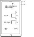
- FIG. 3is a diagram showing an example of a screen for selecting a charging power supply desired by the user in the information terminal according to the embodiment.
- FIG. 4is a diagram showing another example of a screen for selecting a charging power supply desired by the user in the information terminal according to the embodiment.
- FIG. 5is a diagram showing an example of a screen presented to the user in the information terminal according to the embodiment.
- FIG. 6is a diagram showing an example of a reservation completion screen for a recommended charging facility in the information terminal according to the embodiment.
- FIG. 7is a flow chart showing an example of the operation of the charging management system according to the embodiment.
- a charging management methodincludes a first obtaining step, a second obtaining step, a charging information generating step, and a presenting step.
- the first obtaining stepposition information of the electric vehicle and battery information regarding the remaining capacity of a storage battery mounted on the electric vehicle are obtained.
- desired power source information regarding a charging power source for the storage battery desired by the user of the electric vehicleis acquired.
- charging information generating stepcharging information relating to charging of the storage battery is generated based on the battery information obtained in the first obtaining step and the desired power source information obtained in the second obtaining step.
- location information of a recommended charging facility recommended to the userbased on the location information of the electric vehicle among the plurality of charging facilities acquired in the first acquiring step, and the charging information generated in the charging information generating step Presenting charging information to the user.
- the usercan present the user with the recommended charging equipment 31 that can be charged with the charging power supply 4 desired by the user. Therefore, there is an advantage that the storage battery 21 mounted on the electric vehicle 2 can be easily charged with the charging power source 4 desired by the user.
- the usercan charge the storage battery 21 with the charging power source 4 configured to give priority to economic efficiency, charge the storage battery 21 with the charging power source 4 configured to give priority to environmental friendliness, etc., and meet the various needs of the user. It has the advantage of being possible.
- the charging power supplymay include a first power supply derived from renewable energy for the user and a second power supply derived from energy other than renewable energy.
- the charging management methodmay further include a prediction step and a power procurement step.
- the prediction stepcharging demand in each of the plurality of charging facilities is predicted based on the battery information acquired in the first acquisition step and the desired power source information acquired in the second acquisition step.
- the power supply procurement stepthe charging power supply is procured for each of the plurality of charging facilities based on the charging demand predicted by the prediction step.
- the charging management methodmay further include a third acquiring step of acquiring reservation information regarding whether there is a reservation for charging at the recommended charging facility presented by the presenting step. Then, in the prediction step, the charging demand may be predicted further based on the reservation information acquired in the third acquisition step.
- the presentation stepmay further present the cost required for charging the storage battery.
- route information regarding the planned travel route of the electric vehiclemay be further acquired.
- position information of the recommended charging equipmentmay be presented further based on the route information acquired in the first acquiring step.
- the userdoes not have to go to the charging facility 3 located outside the planned travel route, so there is an advantage that the user's convenience is improved.
- a program according to one aspect of the present disclosurecauses one or more processors to execute the charge management method.
- the usercan present the user with the recommended charging equipment 31 that can be charged with the charging power supply 4 desired by the user. Therefore, there is an advantage that the storage battery 21 mounted on the electric vehicle 2 can be easily charged with the charging power source 4 desired by the user.
- the usercan charge the storage battery 21 with the charging power source 4 configured to give priority to economic efficiency, charge the storage battery 21 with the charging power source 4 configured to give priority to environmental friendliness, etc., and meet the various needs of the user. It has the advantage of being possible.
- a charging management systemincludes a first acquisition unit, a second acquisition unit, a charging information generation unit, and a presentation unit.
- the first acquisition unitacquires position information of the electric vehicle and battery information related to the remaining capacity of a storage battery mounted on the electric vehicle.
- the second acquisition unitacquires desired power source information regarding a charging power source for the storage battery desired by a user of the electric vehicle.
- the charge information generation unitgenerates charge information regarding charging of the storage battery based on the battery information acquired by the first acquisition unit and the desired power source information acquired by the second acquisition unit.
- the presenting unitprovides position information of recommended charging facilities recommended to the user based on the position information of the electric vehicle acquired by the first acquiring unit among a plurality of charging facilities, and the charging information generated by the charging information generating unit. Presenting charging information to the user.
- the usercan present the user with the recommended charging equipment 31 that can be charged with the charging power supply 4 desired by the user. Therefore, there is an advantage that the storage battery 21 mounted on the electric vehicle 2 can be easily charged with the charging power source 4 desired by the user.
- the usercan charge the storage battery 21 with the charging power source 4 configured to give priority to economic efficiency, charge the storage battery 21 with the charging power source 4 configured to give priority to environmental friendliness, etc., and meet the various needs of the user. It has the advantage of being possible.
- FIG. 1is a diagram showing an overview of a charging management system 100 according to an embodiment.
- the charging management system 100is a system for managing charging of the storage battery 21 in the electric vehicle 2 on which the storage battery 21 is mounted. Charging of the storage battery 21 is performed by supplying electric power from the charging power supply 4 to the storage battery 21 of the electric vehicle 2 via the charging facility 3 .
- the electric vehicle 2is a vehicle that uses the electricity stored in the storage battery 21 as an energy source and an electric motor as a power source to run.
- the electric vehicle 2may have multiple energy sources including electricity.
- the electric vehicle 2may be a hybrid vehicle that uses both electricity and gasoline as energy sources and runs using an electric motor and an internal combustion engine as power sources, respectively.
- the electric vehicle 2is an electric vehicle. It should be noted that the electric vehicle 2 may include a motorcycle, a bicycle, or the like, in addition to an automobile.
- the charging management system 100manages the electric vehicles 2 owned or temporarily rented by users who have entered into a usage contract with the business operator that operates the charging management system 100 .
- the charging power source 4is connected to the charging facility 3 via power transmission equipment and/or transformer equipment, and supplies power to the storage battery 21 mounted on the electric vehicle 2 via the charging equipment 3 .
- charging power source 4includes a plurality of power sources having different power generation modes.
- the charging power source 4includes a first power source 41 derived from renewable energy and a second power source 42 derived from energy other than renewable energy (hereinafter also referred to as “fossil energy, etc.”).
- the first power supply 41may include, for example, a power supply that supplies power generated by photovoltaic power generation, and a power supply that supplies power generated by hydraulic power generation, wind power generation, geothermal power generation, or biomass power generation.
- the first power supply 41is a power supply suitable for a so-called decarbonized society in which fossil fuels such as oil and coal are used to prevent emissions of greenhouse gases such as carbon dioxide that cause global warming. is.
- a power supply that supplies power generated by solar power generation and a power supply that supplies power generated by wind power generationare illustrated.
- the second power supply 42may include, for example, a power supply that supplies power generated by thermal power generation, nuclear power generation, or the like.
- a power source that supplies electric power generated by nuclear power generationis a power source that can adapt to the decarbonized society described above, but is included in the second power source 42 because it is not derived from renewable energy.
- FIG. 1illustrates a power supply that supplies electric power generated by thermal power generation as an example of the second power supply 42 .
- the charging facility 3is installed by the operator or another operator affiliated with the operator in the area (for example, the entire country) where the operator who operates the charging management system 100 provides services.
- a plurality of (for example, several thousand) charging facilities 3are distributed and installed in the area. Only one charging facility 3 may be installed at each installation location, or several or more than ten charging facilities may be installed.
- the charging facility 3may include, for example, a quick charger with a higher output than the normal charger, in addition to the normal charger. Also, the charging facility 3 may include a charger with a charging cable in addition to the outlet-type charger.
- the charging facility 3is a socket-type charger
- the power plug provided at one end of the charging cable mounted on the electric vehicle 2is inserted, and the charging connector provided at the other end of the charging cable is connected to the electric vehicle 2 .
- the charging equipment 3is a charger with a charging cable
- the storage battery 21 of the electric vehicle 2can be charged by connecting a charging connector provided at one end of the charging cable to a charging port provided in the electric vehicle 2. It is possible to charge.
- the charging facility 3may be a wireless power supply type charger.
- the charging equipment 3is a wireless power supply type charger, by using electromagnetic induction technology, power is supplied from the power transmission coil embedded in the road surface to the power reception coil mounted on the electric vehicle 2 in a non-contact manner. It is possible to charge the storage battery 21 of the vehicle 2 .
- the charging management system 100is configured by, for example, a server device. In the following description, unless otherwise specified, one electric vehicle 2 or one user will be focused on. In practice, the charging management system 100 executes the processing described below for each electric vehicle 2 or each user.
- FIG. 2is a block diagram showing the configuration of the charging management system 100 according to the embodiment.
- the charging management system 100includes a first acquisition unit 11, a second acquisition unit 12, a third acquisition unit 13, a charging information generation unit 14, a presentation unit 15, and a prediction unit 16. , and a power supply unit 17 .
- the first acquisition unit 11acquires position information of the electric vehicle 2 and battery information regarding the remaining capacity of the storage battery 21 mounted on the electric vehicle 2 .
- the first acquisition unit 11is the execution subject of the first acquisition step ST1 (see FIG. 7) in the charging management method.
- the position information of the electric vehicle 2includes, for example, coordinates of the current position of the electric vehicle 2 determined by a positioning system such as GPS (Global Positioning System).
- the battery informationmay include, for example, the current remaining capacity of the storage battery 21, or the chargeable capacity obtained by subtracting the current remaining capacity from the fully charged capacity.
- the battery informationmay include SoC (State of Charge).
- the first acquisition unit 11requests, for example, a server device operated by a manufacturer that manufactures the electric vehicle 2 via a communication network such as the Internet, so that the location information and the battery information of the electric vehicle 2 are sent from the server device. Get information regularly. This is because such a manufacturer manages the state of the electric vehicle 2 by periodically acquiring position information and battery information of the electric vehicle 2 from the electric vehicle 2 . Note that the first acquisition unit 11 may directly acquire the position information and the battery information of the electric vehicle 2 by communicating with the electric vehicle 2 via a communication network.
- the second acquisition unit 12acquires desired power source information regarding the charging power source 4 of the storage battery 21 desired by the user of the electric vehicle 2 .
- the second acquisition unit 12is the executing entity of the second acquisition step ST2 (see FIG. 7) in the charging management method.
- Desired power source informationmay include, for example, information indicating that the user desires charging using either one of the first power source 41 and the second power source 42 .
- the desired power source informationis information about the usage ratio of each of the first power source 41 and the second power source 42 if the user desires charging using both the first power source 41 and the second power source 42, for example. can include
- the second acquisition unit 12acquires the desired power supply information input at the information terminal 5 by communicating with the information terminal 5 owned by the user via a communication network.
- the information terminal 5may include a stationary terminal such as a desktop or laptop personal computer as well as a portable terminal such as a smart phone or a tablet terminal.
- the information terminal 5is installed with a dedicated application for using the charging management system 100 .
- the usercan select the charging power source 4 desired by the user.
- FIG. 3is a diagram showing an example of a screen for selecting the charging power source 4 desired by the user in the information terminal 5 according to the embodiment.
- the display unit 51displays a message M1 "Please select the type of electricity to be charged", a first icon I1 including a character string "ordinary electricity”, A second icon I2 including a character string "electricity (renewable energy)" is displayed.
- the information terminal 5When the user selects the first icon I1 by, for example, touching the display unit 51 with a finger, the information terminal 5 generates desired power source information including the desire to use the second power source 42 as the charging power source 4. A signal including desired power source information is transmitted to charging management system 100 via a communication network. Further, when the user selects the second icon I2 by, for example, touching the display unit 51 with a finger, the information terminal 5 generates desired power source information including the desire to use the first power source 41 as the charging power source 4, A signal including the generated desired power source information is transmitted to the charging management system 100 via the communication network. The second acquisition unit 12 acquires desired power supply information by receiving these signals.
- the display unit 51 of the information terminal 5may display a screen as shown in FIG. 4, for example.
- FIG. 4is a diagram showing another example of the screen for selecting the charging power source 4 desired by the user in the information terminal 5 according to the embodiment.
- a message M2"Please input the rate of electricity to be charged” and the usage rate of electricity derived from "renewable energy” (that is, renewable energy) are input.
- a second text box TB2for inputting the usage rate of electricity derived from "other than renewable energy” (that is, fossil energy, etc.).
- the display unit 51displays the total value of the usage ratio of electricity derived from “renewable energy” and electricity derived from “non-renewable energy”.
- the information terminal 5displays the usage ratio of the first power supply 41 as the charging power supply 4. , and the usage ratio of the second power supply 42 as the charging power supply 4, and transmits a signal including the generated desired power supply information to the charging management system 100 via the communication network.
- the second acquisition unit 12acquires the desired power supply information by receiving the signal.
- the display unit 51may display a text box for the user to input the time slot for charging the storage battery 21 .
- the desired power source informationincludes the time period during which the user charges the storage battery 21 .
- the display unit 51may display the unit price of charging (that is, the cost of charging per 1 kWh).
- the unit price of charging when the first icon I1 is selected and the unit price of charging when the second icon I2 is selectedmay be displayed on the display unit 51 .
- the unit price of chargingmay be displayed according to the usage ratio entered in each of the first text box TB1 and the second text box TB2.
- the charging unit priceis displayed on the display unit 51 when the presentation unit 15 (presentation step ST5) described later transmits a signal including the charging unit price to the information terminal 5 . That is, it can be said that the presentation unit 15 (presentation step ST5) further presents the cost required for charging the storage battery 21 .
- the timing of presenting the unit price of chargingmay be the time when the screen shown in FIG. 3 or FIG. may be the timing for presenting the position information and the like of the recommended charging facility 31 (see FIG. 5).
- the charging information generation unit 14generates the storage battery 21 based on the battery information acquired by the first acquisition unit 11 (first acquisition step ST1) and the desired power source information acquired by the second acquisition unit 12 (second acquisition step ST2). to generate charging information about the charging of the
- the charge information generation unit 14is the main body that executes the charge information generation step ST4 in the charge management method.
- the charging informationmay include information indicating the type of charging power supply 4 included in the desired power supply information and the amount of charge required to fully charge the storage battery 21 calculated based on the battery information.
- the charge informationmay include information indicating the amount of charge required to fully charge the storage battery 21 for each power source.
- the charging informationmay include information indicating the cost required to fully charge the storage battery 21 , that is, the cost required for charging the storage battery 21 .
- the costmay be the unit price of charging or the total cost of charging the storage battery 21 .
- the presentation unit 15presents the location information of the recommended charging equipment 31 and the charging information generated by the charging information generating unit 14 (charging information generating step ST4) to the user.
- the presentation unit 15is the execution subject of the presentation step ST5 in the charging management method.
- the recommended charging facility 31is the charging facility 3 recommended to the user based on the position information of the electric vehicle 2 acquired by the first acquisition unit 11 (first acquisition step ST1) among the plurality of charging facilities 3 .
- the recommended charging facility 31is a charging facility 3 that can charge the storage battery 21 using the charging power supply 4 desired by the user, and is, for example, the current location of the user (that is, the location of the electric vehicle 2). It is the charging facility 3 closest to the current position). For example, when the user specifies a time slot for charging the storage battery 21, the recommended charging facility 31 is the charging facility 3 closest to the estimated position of the electric vehicle 2 in the specified time slot.
- the recommended charging facility 31is located on the planned travel route or in the vicinity of the planned travel route.
- the first acquisition unit 11further acquires route information regarding the planned travel route of the electric vehicle 2, for example, by communicating with the electric vehicle 2 via a communication network.
- the presentation unit 15presents the position information of the recommended charging facility 31 further based on the route information acquired by the first acquisition unit 11 (first acquisition step ST1).
- the presentation unit 15generates presentation information including position information and charging information of the recommended charging equipment 31, and transmits a signal including the generated presentation information to the information terminal 5 via the communication network.
- the information terminal 5Upon receiving the signal, the information terminal 5 causes the display unit 51 to display the presentation information included in the signal. That is, the presentation unit 15 presents the location information and charging information of the recommended charging equipment 31 to the user via the information terminal 5 .
- FIG. 5is a diagram showing an example of a screen presented to the user on the information terminal 5 according to the embodiment.
- the display unit 51displays the current position P1 of the electric vehicle 2, the installation location of “charging facility A” that is the recommended charging facility 31, and the current position P1 of the electric vehicle 2 to “charging facility A”. , and a map including the driving route to the installation location of . Further, the display unit 51 displays a message M3 "Do you want to reserve charging at the charging facility A?" 4 icon I4 is displayed.
- the presentation unit 15displays a character string or the like indicating charge information such as the type of the charging power source 4 and/or the charge amount required to fully charge the storage battery 21, for example. , is displayed on the display unit 51 .
- the presentation unit 15may cause the display unit 51 to further display the estimated time required to reach the "charging facility A".
- the third acquisition unit 13acquires reservation information regarding whether there is a reservation for charging at the recommended charging equipment 31 presented by the presentation unit 15 (presentation step ST5).
- the third acquisition unit 13is the execution subject of the third acquisition step ST3 (see FIG. 7) in the charging management method.
- the third acquisition unit 13acquires the reservation information input by the user on the information terminal 5 by communicating with the information terminal 5 via the communication network.
- the screen shown in FIG.generates reservation information including a reservation for charging at the recommended charging facility 31, and transmits a signal including the generated reservation information to the charging management system 100 via a communication network.
- the third acquisition unit 13acquires reservation information by receiving the signal.
- the presentation unit 15causes the display unit 51 to display a screen as shown in FIG.
- FIG. 6is a diagram showing an example of a reservation completion screen for the recommended charging facility 31 on the information terminal 5 according to the embodiment.
- the display unit 51displays a map in the same manner as in the example shown in FIG. 5, and displays a message M4 that reads, "Charging at charging facility A has been reserved.”
- the information terminal 5may transmit, for example, a signal including a command requesting re-presentation of the recommended charging facility 31 to the charging management system 100 .
- the presentation unit 15 of the charging management system 100presents to the user a recommended charging facility 31 different from the recommended charging facility 31 presented last time.
- the prediction unit 16selects a plurality of charging facilities based on the battery information acquired by the first acquisition unit 11 (first acquisition step ST1) and the desired power source information acquired by the second acquisition unit 12 (second acquisition step ST2). Predict the charging demand at each of 3.
- the prediction unit 16is the execution entity of the prediction step ST6 in the charging management method.
- the charging demandis the amount of power required to charge the storage battery 21 that is expected to occur in each charging facility 3 in the future, and is the amount of power for each type of charging power supply 4 .
- the power consumptionis predicted for each time period, such as in the morning or every hour.
- the prediction unit 16estimates that each charging facility 3 will be required in the future based on, for example, the battery information (remaining capacity of the storage battery 21) acquired from each electric vehicle 2 and the past charging history in each charging facility 3. Calculate the amount of power. In addition, the prediction unit 16 predicts that each charging facility 3 will need power in the future based on, for example, the user's desired power source information of each electric vehicle 2 and the history of the past usage ratio of the charging power source 4 at each charging facility 3. An estimated usage rate of the charging power source 4 is calculated. The prediction unit 16 predicts charging demand at each charging facility 3 by comprehensively considering these calculation results.
- the prediction unit 16predicts charging demand further based on the reservation information acquired by the third acquisition unit 13 (third acquisition step ST3). That is, the prediction unit 16 can grasp future charging at the recommended charging equipment 31 by referring to the reservation information.
- the chargeis not a predicted charge, but a charge that is generally determined to occur in the future. Therefore, there is an advantage that the accuracy of predicting the charging demand can be expected to be improved by further referring to the reservation information by the prediction unit 16 .
- the power supply procurement unit 17procures the charging power supply 4 for each of the plurality of charging facilities 3 based on the charging demand predicted by the prediction unit 16 (prediction step ST6).
- the power supply procurement unit 17is the execution entity of the power supply procurement step ST7 in the charging management method.
- the power source procuring unit 17procures the charging power source 4 for each charging facility 3 so that the electric power necessary for charging the storage battery 21 at the charging facility 3 in the future will not be insufficient.
- Procurement means for procuring the charging power source 4may include, for example, means for procuring from the charging power source 4 (for example, power plant, etc.) owned by the business operator that operates the charging management system 100 .
- the procurement meansmay include means for procuring power from the charging power supply 4 of the electric power company that owns the charging power supply 4 by concluding a power purchase contract with the power company.
- the procurement meansmay include means for procuring from the charging power supply 4 purchased on the wholesale power exchange market (for example, JEPX (Japan Electric Power Exchange) in Japan).
- the power source procurement unit 17uses one or more procurement means among the plurality of procurement means to procure the charging power source 4 for each charging equipment 3 .
- the power supply procurement unit 17may use different procurement means for each type of charging power supply 4 .
- the power supply procurement unit 17procure the first power supply 41 from the first power supply 41 owned by the first power company, and the second power supply 42 from the second power company different from the first power company. You may procure from the 2nd power supply 42 which it holds.
- the power source procurement unit 17may procure the charging power sources 4 so as to satisfy all the charging demands of the respective charging facilities 3, or may procure only the insufficient charging power sources 4 in the respective charging facilities 3. good.
- FIG. 7is a flow chart showing an example of the operation of the charging management system 100 according to the embodiment.
- the first acquisition unit 11periodically acquires battery information from the electric vehicle 2 (S1).
- Processing S1corresponds to the first acquisition step ST1 in the charging management method. Processing S1 is executed without depending on other processing described below.
- the second acquisition unit 12acquires desired power source information from the information terminal 5 (S2). Processing S2 corresponds to second acquisition step ST2 in the charging management method. Specifically, the second acquisition unit 12 receives a signal including the desired power source information transmitted from the information terminal 5 by the user operating the information terminal 5 to input the desired power source information. Acquire desired power source information.
- the charge information generation unit 14generates charge information based on the battery information acquired by the first acquisition unit 11 and the desired power source information acquired by the second acquisition unit 12 (S3).
- the process S3corresponds to the charge information generation step ST4 in the charge management method.
- the presentation unit 15presents the location information of the recommended charging facility 31 and the charging information generated by the charging information generating unit 14 to the user (S4).
- Processing S4corresponds to presentation step ST5 in the charge management method. Specifically, the presentation unit 15 generates presentation information including position information and charging information of the recommended charging equipment 31, and transmits a signal including the created presentation information to the information terminal 5 via the communication network.
- the third acquisition unit 13receives a signal including reservation information transmitted from the information terminal 5, thereby performing the reservation. Information is acquired (S5). Processing S5 corresponds to the third acquisition step ST3 in the charging management method.
- the prediction unit 16predicts the charging demand of each charging facility 3 based on the battery information of each electric vehicle 2 acquired by the first acquisition unit 11 and the desired power source information of each user acquired by the second acquisition unit 12. (S6).
- Processing S6corresponds to prediction step ST6 in the charging management method.
- the process S6is executed, for example, each time the first acquisition unit 11 acquires battery information or each time the second acquisition unit 12 acquires desired power supply information. Further, the process S6 is executed, for example, each time the third acquisition unit 13 acquires reservation information.
- the power source procuring unit 17procures the charging power source 4 for each charging facility 3 based on the charging demand of each charging facility 3 predicted by the prediction unit 16 (S7).
- the process S7corresponds to the power procurement step ST7 in the charging management method. Processing S7 is performed, for example, each time the prediction unit 16 predicts the charging demand.
- the above series of processesare repeated.
- the charging management system 100(charging management method) according to the embodiment, it is possible to present to the user recommended charging equipment 31 that can be charged with the charging power supply 4 desired by the user. Therefore, in the embodiment, there is an advantage that the storage battery 21 mounted on the electric vehicle 2 can be easily charged with the charging power source 4 desired by the user.
- the usercharges the storage battery 21 with the charging power supply 4 configured to give priority to economic efficiency, charges the storage battery 21 with the charging power supply 4 configured to give priority to environmental friendliness, and so on. It has the advantage of being able to respond to the diverse needs of
- the second acquisition unit 12may further subdivide and acquire the type of charging power supply 4 desired by the user.
- the second acquisition unit 12not only acquires the desire to use the first power source 41 as the charging power source 4, but also acquires a power source that supplies power generated by solar power generation or a power source that is generated by wind power generation. It is also possible to obtain a request for a power source or the like that supplies the electric power to be used as the charging power source 4 .
- the third acquisition unit 13may acquire reservation information regarding not only one charging reservation but also multiple charging reservations.
- the usermay reserve multiple times of charging, for example, charging at the recommended charging facility 31 every several days.
- the presentation unit 15(presentation step ST5) is not limited to presenting one recommended charging facility 31, and may present a plurality of recommended charging facilities 31.
- the usermay select the charging facility 3 that the user wants to use from the plurality of recommended charging facilities 31 presented.
- the prediction unit 16predicts the charging demand of each charging facility 3 without referring to the reservation information acquired by the third acquisition unit 13 (third acquisition step ST3). good too.
- the charging management system 100does not have to include the third acquisition unit 13 .
- the charging management methodmay not include the third acquisition step ST3.
- the charging management system 100(charging management method) only presents the recommended charging facility 31 to the user, predicts the charging demand at each charging facility 3, and It is not necessary to procure the power supply 4 for
- the prediction of charging demand at each charging facility 3 and the procurement of the charging power source 4 for each charging facility 3may be performed by a system other than the charging management system 100 .
- the charging management system 100does not have to include the prediction unit 16 and the power procurement unit 17 .
- the charging management methodmay not include the prediction step ST6 and the power procurement step ST7.
- the desired power source informationindicates whether the user desires charging with the first power source 41 derived from renewable energy or whether the user desires charging with the second power source 42 derived from fossil energy or the like.
- Informationincludes, but is not limited to.
- the desired power source informationmay include only information requesting charging with one or more power sources from a plurality of types of power sources as the first power source 41 .
- the userdesires at least one of, for example, a power supply that supplies power generated by solar power generation and a power supply that supplies power generated by wind power generation as the charging power supply 4, and the second power supply 42 need not be included in the options.
- the desired power source informationmay include only information requesting charging with one or more power sources from a plurality of types of power sources as the second power source 42 .
- the userdesires at least one of, for example, a power supply that supplies power generated by thermal power generation and a power supply that supplies power generated by nuclear power generation as the charging power supply 4 . may not be included in the options.
- machine learningmay be used to calculate the charging demand by the prediction unit 16 .
- machine learningis performed using various parameters such as time period and past charging history as inputs. Since charging demand changes from moment to moment, machine learning may be performed so that newer parameters and data have higher priority.
- each processing unit included in the charging management system 100 and the like according to the above embodimentis typically realized as an LSI, which is an integrated circuit. These may be made into one chip individually, or may be made into one chip so as to include part or all of them.
- circuit integrationis not limited to LSIs, and may be realized with dedicated circuits or general-purpose processors.
- An FPGAField Programmable Gate Array
- a reconfigurable processorthat can reconfigure the connections and settings of the circuit cells inside the LSI may be used.
- each componentmay be configured with dedicated hardware or realized by executing a software program suitable for each component.
- Each componentmay be realized by reading and executing a software program recorded in a recording medium such as a hard disk or a semiconductor memory by a program execution unit such as a CPU or processor.
- the division of functional blocks in the block diagramis an example, and a plurality of functional blocks can be realized as one functional block, one functional block can be divided into a plurality of functional blocks, and some functions can be moved to other functional blocks.
- single hardware or softwaremay process the functions of a plurality of functional blocks having similar functions in parallel or in a time-sharing manner.
- each step in the flowchartis executed is for illustrative purposes in order to specifically describe the present disclosure, and orders other than the above may be used. Also, some of the above steps may be executed concurrently (in parallel) with other steps.
- charging management system 100was realized as a single device, but may be realized by a plurality of devices.
- charging management system 100is realized by a plurality of devices, the components included in charging management system 100 may be distributed among the plurality of devices in any way.
- the present disclosuremay be implemented by cloud computing or by edge computing.
- the present disclosurecan be applied, for example, to a system for managing charging of a storage battery in an electric vehicle equipped with a storage battery.
Landscapes
- Engineering & Computer Science (AREA)
- Business, Economics & Management (AREA)
- Radar, Positioning & Navigation (AREA)
- Remote Sensing (AREA)
- Power Engineering (AREA)
- Transportation (AREA)
- Mechanical Engineering (AREA)
- Physics & Mathematics (AREA)
- General Physics & Mathematics (AREA)
- Economics (AREA)
- Health & Medical Sciences (AREA)
- Strategic Management (AREA)
- Theoretical Computer Science (AREA)
- Tourism & Hospitality (AREA)
- General Business, Economics & Management (AREA)
- Marketing (AREA)
- Human Resources & Organizations (AREA)
- Primary Health Care (AREA)
- General Health & Medical Sciences (AREA)
- Automation & Control Theory (AREA)
- Public Health (AREA)
- Water Supply & Treatment (AREA)
- Accounting & Taxation (AREA)
- Development Economics (AREA)
- Finance (AREA)
- Entrepreneurship & Innovation (AREA)
- Game Theory and Decision Science (AREA)
- Charge And Discharge Circuits For Batteries Or The Like (AREA)
Abstract
Description
Translated fromJapanese本開示は、蓄電池を搭載する電動車両における蓄電池の充電を管理する充電管理方法、プログラム、及び充電管理システムに関する。The present disclosure relates to a charging management method, program, and charging management system for managing charging of a storage battery in an electric vehicle equipped with a storage battery.
特許文献1には、太陽光発電モジュール等の発電装置、又は定置型蓄電池等の充放電装置を連係した電気自動車用の急速充電設備及び充電設備システムに関し、充電設備に連携する各装置のエネルギーマネジメント方法が開示されている。Patent Document 1 relates to a rapid charging facility and charging facility system for electric vehicles that are linked to a power generation device such as a photovoltaic module or a charging and discharging device such as a stationary storage battery. Energy management of each device linked to the charging facility A method is disclosed.
また、特許文献2には、局所的に生成される太陽光充電容量を含む充電システム内の電気自動車に充電容量を分配する方法が開示されている。
本開示は、電動車両に搭載されている蓄電池を、ユーザが希望する充電用電源で充電しやすくなる充電管理方法、プログラム、及び充電管理システムを提供することを目的とする。An object of the present disclosure is to provide a charging management method, a program, and a charging management system that make it easier for a user to charge a storage battery mounted on an electric vehicle with a charging power supply desired by the user.
本開示の一態様に係る充電管理方法は、第1取得ステップと、第2取得ステップと、充電情報生成ステップと、提示ステップと、を含む。前記第1取得ステップでは、電動車両の位置情報、及び前記電動車両に搭載されている蓄電池の残容量に関する電池情報を取得する。前記第2取得ステップでは、前記電動車両のユーザが希望する前記蓄電池の充電用電源に関する希望電源情報を取得する。前記充電情報生成ステップでは、前記第1取得ステップが取得した前記電池情報、及び前記第2取得ステップが取得した前記希望電源情報に基づいて、前記蓄電池の充電に関する充電情報を生成する。前記提示ステップでは、複数の充電設備のうち前記第1取得ステップが取得した前記電動車両の位置情報に基づいて前記ユーザに推奨する推奨充電設備の位置情報、及び前記充電情報生成ステップが生成した前記充電情報を前記ユーザに提示する。A charging management method according to an aspect of the present disclosure includes a first obtaining step, a second obtaining step, a charging information generating step, and a presenting step. In the first obtaining step, position information of the electric vehicle and battery information regarding the remaining capacity of a storage battery mounted on the electric vehicle are obtained. In the second acquiring step, desired power source information regarding a charging power source for the storage battery desired by the user of the electric vehicle is acquired. In the charging information generating step, charging information relating to charging of the storage battery is generated based on the battery information obtained in the first obtaining step and the desired power source information obtained in the second obtaining step. In the presenting step, location information of a recommended charging facility recommended to the user based on the location information of the electric vehicle among the plurality of charging facilities acquired in the first acquiring step, and the charging information generated in the charging information generating step Presenting charging information to the user.
本開示の一態様に係るプログラムは、1以上のプロセッサに、前記充電管理方法を実行させる。A program according to one aspect of the present disclosure causes one or more processors to execute the charging management method.
本開示の一態様に係る充電管理システムは、第1取得部と、第2取得部と、充電情報生成部と、提示部と、を備える。前記第1取得部は、電動車両の位置情報、及び前記電動車両に搭載されている蓄電池の残容量に関する電池情報を取得する。前記第2取得部は、前記電動車両のユーザが希望する前記蓄電池の充電用電源に関する希望電源情報を取得する。前記充電情報生成部は、前記第1取得部が取得した前記電池情報、及び前記第2取得部が取得した前記希望電源情報に基づいて、前記蓄電池の充電に関する充電情報を生成する。前記提示部は、複数の充電設備のうち前記第1取得部が取得した前記電動車両の位置情報に基づいて前記ユーザに推奨する推奨充電設備の位置情報、及び前記充電情報生成部が生成した前記充電情報を前記ユーザに提示する。A charging management system according to an aspect of the present disclosure includes a first acquisition unit, a second acquisition unit, a charging information generation unit, and a presentation unit. The first acquisition unit acquires position information of the electric vehicle and battery information related to the remaining capacity of a storage battery mounted on the electric vehicle. The second acquisition unit acquires desired power source information regarding a charging power source for the storage battery desired by a user of the electric vehicle. The charge information generation unit generates charge information regarding charging of the storage battery based on the battery information acquired by the first acquisition unit and the desired power source information acquired by the second acquisition unit. The presenting unit provides position information of recommended charging facilities recommended to the user based on the position information of the electric vehicle acquired by the first acquiring unit among a plurality of charging facilities, and the charging information generated by the charging information generating unit. Presenting charging information to the user.
本開示は、電動車両に搭載されている蓄電池を、ユーザが希望する充電用電源で充電しやすくなる、という利点がある。The present disclosure has the advantage of making it easier to charge the storage battery mounted on the electric vehicle with the charging power source desired by the user.
本開示の一態様に係る充電管理方法は、第1取得ステップと、第2取得ステップと、充電情報生成ステップと、提示ステップと、を含む。前記第1取得ステップでは、電動車両の位置情報、及び前記電動車両に搭載されている蓄電池の残容量に関する電池情報を取得する。前記第2取得ステップでは、前記電動車両のユーザが希望する前記蓄電池の充電用電源に関する希望電源情報を取得する。前記充電情報生成ステップでは、前記第1取得ステップが取得した前記電池情報、及び前記第2取得ステップが取得した前記希望電源情報に基づいて、前記蓄電池の充電に関する充電情報を生成する。前記提示ステップでは、複数の充電設備のうち前記第1取得ステップが取得した前記電動車両の位置情報に基づいて前記ユーザに推奨する推奨充電設備の位置情報、及び前記充電情報生成ステップが生成した前記充電情報を前記ユーザに提示する。A charging management method according to an aspect of the present disclosure includes a first obtaining step, a second obtaining step, a charging information generating step, and a presenting step. In the first obtaining step, position information of the electric vehicle and battery information regarding the remaining capacity of a storage battery mounted on the electric vehicle are obtained. In the second acquiring step, desired power source information regarding a charging power source for the storage battery desired by the user of the electric vehicle is acquired. In the charging information generating step, charging information relating to charging of the storage battery is generated based on the battery information obtained in the first obtaining step and the desired power source information obtained in the second obtaining step. In the presenting step, location information of a recommended charging facility recommended to the user based on the location information of the electric vehicle among the plurality of charging facilities acquired in the first acquiring step, and the charging information generated in the charging information generating step Presenting charging information to the user.
これによれば、ユーザが希望する充電用電源4で充電可能な推奨充電設備31をユーザに提示することができる。このため、電動車両2に搭載されている蓄電池21を、ユーザが希望する充電用電源4で充電しやすくなる、という利点がある。つまり、ユーザが経済性を優先した構成の充電用電源4で蓄電池21を充電したり、環境性を優先した構成の充電用電源4で蓄電池21を充電したり等、ユーザの多様なニーズに対応可能である、という利点がある。According to this, it is possible to present the user with the recommended
例えば、前記充電用電源は、前記ユーザが再生可能エネルギー由来の第1電源と、再生可能エネルギー以外のエネルギー由来の第2電源と、を含んでいてもよい。For example, the charging power supply may include a first power supply derived from renewable energy for the user and a second power supply derived from energy other than renewable energy.
これによれば、環境性を考慮して再生可能エネルギー由来の電気を利用したいというユーザのニーズ、及び経済性を考慮して再生可能エネルギー以外のエネルギー由来の電気を利用したいというニーズの両方に対応することができる、という利点がある。According to this, it is possible to meet both the needs of users who want to use electricity derived from renewable energy in consideration of environmental friendliness, and the needs of users who want to use electricity derived from energy other than renewable energy in consideration of economic efficiency. It has the advantage of being able to
例えば、前記充電管理方法は、予測ステップと、電源調達ステップと、を更に含んでいてもよい。前記予測ステップでは、前記第1取得ステップが取得した前記電池情報、及び前記第2取得ステップが取得した前記希望電源情報に基づいて、前記複数の充電設備の各々での充電需要を予測する。前記電源調達ステップでは、前記予測ステップが予測した前記充電需要に基づいて、前記複数の充電設備の各々に前記充電用電源を調達する。For example, the charging management method may further include a prediction step and a power procurement step. In the prediction step, charging demand in each of the plurality of charging facilities is predicted based on the battery information acquired in the first acquisition step and the desired power source information acquired in the second acquisition step. In the power supply procurement step, the charging power supply is procured for each of the plurality of charging facilities based on the charging demand predicted by the prediction step.
これによれば、複数の充電設備3の各々において、ユーザが希望する充電用電源4が不足するといった事態を回避しやすい、という利点がある。According to this, there is an advantage that it is easy to avoid a situation in which the
例えば、前記充電管理方法は、前記提示ステップが提示した前記推奨充電設備での充電の予約の有無に関する予約情報を取得する第3取得ステップを更に含んでいてもよい。そして、前記予測ステップでは、前記第3取得ステップが取得した前記予約情報に更に基づいて、前記充電需要を予測してもよい。For example, the charging management method may further include a third acquiring step of acquiring reservation information regarding whether there is a reservation for charging at the recommended charging facility presented by the presenting step. Then, in the prediction step, the charging demand may be predicted further based on the reservation information acquired in the third acquisition step.
これによれば、予測される充電ではなく、将来起こり得ることが概ね確定した推奨充電設備31での将来の充電を参照することにより、充電需要を予測する精度の向上が期待できる、という利点がある。According to this, by referring to the future charging at the recommended
例えば、前記提示ステップでは、前記蓄電池の充電に要するコストを更に提示してもよい。For example, the presentation step may further present the cost required for charging the storage battery.
これによれば、ユーザが蓄電池21の充電に要するコストを把握することができるので、環境性又は経済性のいずれを優先して蓄電池21を充電するかをユーザが選択しやすくなり、ユーザの利便性の向上が期待できる、という利点がある。According to this, since the user can grasp the cost required for charging the
例えば、前記第1取得ステップでは、前記電動車両の走行予定経路に関する経路情報を更に取得してもよい。そして、前記提示ステップでは、前記第1取得ステップが取得した前記経路情報に更に基づいて、前記推奨充電設備の位置情報を提示してもよい。For example, in the first acquisition step, route information regarding the planned travel route of the electric vehicle may be further acquired. Then, in the presenting step, position information of the recommended charging equipment may be presented further based on the route information acquired in the first acquiring step.
これによれば、ユーザが走行予定経路から外れた位置にある充電設備3に赴かずに済むので、ユーザの利便性が向上する、という利点がある。According to this, the user does not have to go to the
また、本開示の一態様に係るプログラムは、1以上のプロセッサに、前記充電管理方法を実行させる。A program according to one aspect of the present disclosure causes one or more processors to execute the charge management method.
これによれば、ユーザが希望する充電用電源4で充電可能な推奨充電設備31をユーザに提示することができる。このため、電動車両2に搭載されている蓄電池21を、ユーザが希望する充電用電源4で充電しやすくなる、という利点がある。つまり、ユーザが経済性を優先した構成の充電用電源4で蓄電池21を充電したり、環境性を優先した構成の充電用電源4で蓄電池21を充電したり等、ユーザの多様なニーズに対応可能である、という利点がある。According to this, it is possible to present the user with the recommended
また、本開示の一態様に係る充電管理システムは、第1取得部と、第2取得部と、充電情報生成部と、提示部と、を備える。前記第1取得部は、電動車両の位置情報、及び前記電動車両に搭載されている蓄電池の残容量に関する電池情報を取得する。前記第2取得部は、前記電動車両のユーザが希望する前記蓄電池の充電用電源に関する希望電源情報を取得する。前記充電情報生成部は、前記第1取得部が取得した前記電池情報、及び前記第2取得部が取得した前記希望電源情報に基づいて、前記蓄電池の充電に関する充電情報を生成する。前記提示部は、複数の充電設備のうち前記第1取得部が取得した前記電動車両の位置情報に基づいて前記ユーザに推奨する推奨充電設備の位置情報、及び前記充電情報生成部が生成した前記充電情報を前記ユーザに提示する。Also, a charging management system according to an aspect of the present disclosure includes a first acquisition unit, a second acquisition unit, a charging information generation unit, and a presentation unit. The first acquisition unit acquires position information of the electric vehicle and battery information related to the remaining capacity of a storage battery mounted on the electric vehicle. The second acquisition unit acquires desired power source information regarding a charging power source for the storage battery desired by a user of the electric vehicle. The charge information generation unit generates charge information regarding charging of the storage battery based on the battery information acquired by the first acquisition unit and the desired power source information acquired by the second acquisition unit. The presenting unit provides position information of recommended charging facilities recommended to the user based on the position information of the electric vehicle acquired by the first acquiring unit among a plurality of charging facilities, and the charging information generated by the charging information generating unit. Presenting charging information to the user.
これによれば、ユーザが希望する充電用電源4で充電可能な推奨充電設備31をユーザに提示することができる。このため、電動車両2に搭載されている蓄電池21を、ユーザが希望する充電用電源4で充電しやすくなる、という利点がある。つまり、ユーザが経済性を優先した構成の充電用電源4で蓄電池21を充電したり、環境性を優先した構成の充電用電源4で蓄電池21を充電したり等、ユーザの多様なニーズに対応可能である、という利点がある。According to this, it is possible to present the user with the recommended
なお、これらの包括的又は具体的な態様は、システム、方法、集積回路、コンピュータプログラム又はコンピュータ読み取り可能なCD-ROMなどの記録媒体で実現されてもよく、システム、方法、集積回路、コンピュータプログラム及び記録媒体の任意な組み合わせで実現されてもよい。In addition, these general or specific aspects may be realized by a system, method, integrated circuit, computer program, or a recording medium such as a computer-readable CD-ROM. and any combination of recording media.
以下、実施の形態について、図面を参照しながら具体的に説明する。なお、以下で説明する実施の形態は、いずれも本開示の一具体例を示すものである。以下の実施の形態で示される数値、形状、材料、構成要素、構成要素の配置位置及び接続形態、ステップ、ステップの順序などは、一例であり、本開示を限定する主旨ではない。また、以下の実施の形態における構成要素のうち、最上位概念を示す独立請求項に記載されていない構成要素については、任意の構成要素として説明される。Hereinafter, embodiments will be specifically described with reference to the drawings. It should be noted that each of the embodiments described below is a specific example of the present disclosure. Numerical values, shapes, materials, components, arrangement positions and connection forms of components, steps, order of steps, and the like shown in the following embodiments are examples, and are not intended to limit the present disclosure. In addition, among the constituent elements in the following embodiments, constituent elements that are not described in independent claims representing the highest concept will be described as arbitrary constituent elements.
(実施の形態)
[1.概要]
まず、実施の形態に係る充電管理システムの概要を説明する。図1は、実施の形態に係る充電管理システム100の概要を示す図である。図1に示すように、充電管理システム100は、蓄電池21を搭載する電動車両2における蓄電池21の充電を管理するためのシステムである。蓄電池21の充電は、充電設備3を介して、充電用電源4から電動車両2の蓄電池21へ電力を供給することにより実行される。(Embodiment)
[1. Overview]
First, an overview of the charging management system according to the embodiment will be described. FIG. 1 is a diagram showing an overview of a
電動車両2は、蓄電池21に蓄積されている電気をエネルギー源とし、電動機(モータ)を動力源として走行する車両である。電動車両2は、電気を含めて複数のエネルギー源を有していてもよい。例えば、電動車両2は、電気及びガソリンの両方をエネルギー源とし、それぞれ電動機(モータ)及び内燃機関(エンジン)を動力源として走行するハイブリッド型の車両であってもよい。実施の形態では、電動車両2は、電気自動車である。なお、電動車両2は、自動車の他に、自動二輪車、又は自転車等を含み得る。The
実施の形態では、充電管理システム100は、充電管理システム100を運用する事業者との間で利用契約を締結したユーザが所有する又は一時的に借りる電動車両2を管理する。充電管理システム100の管理対象となる電動車両2は、複数台であって、例えば数万台である。In the embodiment, the
充電用電源4は、送電設備及び/又は変電設備を介して充電設備3に接続されており、充電設備3を介して電動車両2に搭載されている蓄電池21に電力を供給する。実施の形態では、充電用電源4は、発電態様が互いに異なる複数の電源を含んでいる。一例として、充電用電源4は、再生可能エネルギー由来の第1電源41と、再生可能エネルギー以外のエネルギー(以下、「化石エネルギー他」ともいう)由来の第2電源42と、を含む。The charging
第1電源41は、例えば太陽光発電により発電された電力を供給する電源の他、水力発電、風力発電、地熱発電、又はバイオマス発電等により発電された電力を供給する電源を含み得る。つまり、第1電源41は、地球温暖化の原因となる二酸化炭素等の温室効果ガスの排出を防ぐために、石油又は石炭等の化石燃料からの脱却を図る、いわゆる脱炭素社会に適合し得る電源である。図1では、第1電源41の一例として、太陽光発電により発電された電力を供給する電源と、風力発電により発電された電力を供給する電源と、を図示している。The
第2電源42は、例えば火力発電、又は原子力発電等により発電された電力を供給する電源等を含み得る。なお、原子力発電により発電された電力を供給する電源は、上述の脱炭素社会に適合し得る電源であるが、再生可能エネルギー由来ではないため、第2電源42に含まれる。図1では、第2電源42の一例として、火力発電により発電された電力を供給する電源を図示している。The
充電設備3は、充電管理システム100を運用する事業者がサービスを提供するエリア(例えば、国全体)において、当該事業者又は当該事業者と提携する他の事業者により設置されている。実施の形態では、上記エリアに複数台(例えば、数千台)の充電設備3が分散して設置されている。なお、充電設備3は、設置箇所ごとに1台のみ設置されていてもよいし、数台又は十数台設置されていてもよい。The charging
充電設備3は、例えば普通充電器の他に、普通充電器よりも出力が大きい急速充電器を含み得る。また、充電設備3は、コンセント型の充電器の他に、充電ケーブル付きの充電器を含み得る。The charging
充電設備3がコンセント型の充電器である場合、電動車両2に搭載されている充電ケーブルの一端に設けられた電源プラグを差し込み、充電ケーブルの他端に設けられた充電用コネクタを電動車両2に設けられた充電口に接続することにより、電動車両2の蓄電池21を充電することが可能である。また、充電設備3が充電ケーブル付きの充電器である場合、充電ケーブルの一端に設けられた充電用コネクタを電動車両2に設けられた充電口に接続することにより、電動車両2の蓄電池21を充電することが可能である。If the
その他、充電設備3は、ワイヤレス給電型の充電器であってもよい。充電設備3がワイヤレス給電型の充電器である場合、電磁誘導の技術を利用して、路面に埋め込まれた送電コイルから電動車両2に搭載された受電コイルへ非接触で給電することにより、電動車両2の蓄電池21を充電することが可能である。In addition, the charging
[2.構成]
次に、充電管理システム100について詳細に説明する。充電管理システム100は、例えばサーバ装置により構成されている。以下では、特に断りのない限り、1台の電動車両2又は1人のユーザに焦点を当てて説明する。実際には、充電管理システム100は、以下に説明する処理を電動車両2ごと又はユーザごとに実行する。[2. Constitution]
Next, charging
図2は、実施の形態に係る充電管理システム100の構成を示すブロック図である。図2に示すように、充電管理システム100は、第1取得部11と、第2取得部12と、第3取得部13と、充電情報生成部14と、提示部15と、予測部16と、電源調達部17と、を備えている。FIG. 2 is a block diagram showing the configuration of the
第1取得部11は、電動車両2の位置情報、及び電動車両2に搭載されている蓄電池21の残容量に関する電池情報を取得する。第1取得部11は、充電管理方法における第1取得ステップST1(図7参照)の実行主体である。電動車両2の位置情報は、例えばGPS(Global Positioning System)等の測位システムにより測位された電動車両2の現在位置の座標等を含む。電池情報は、例えば蓄電池21の現在の残容量、又は満充電時の容量から現在の残容量を差し引いた充電可能な容量等を含み得る。その他、電池情報は、SoC(State of Charge)を含んでいてもよい。The
第1取得部11は、例えば電動車両2を製造する製造業者が運用するサーバ装置に対して、インターネット等の通信網を介して要求することにより、当該サーバ装置から電動車両2の位置情報及び電池情報を定期的に取得する。このような製造業者は、電動車両2から電動車両2の位置情報及び電池情報を定期的に取得することで、電動車両2の状態を管理しているからである。なお、第1取得部11は、電動車両2との間で通信網を介して通信することにより、電動車両2の位置情報及び電池情報を直接的に取得してもよい。The
第2取得部12は、電動車両2のユーザが希望する蓄電池21の充電用電源4に関する希望電源情報を取得する。第2取得部12は、充電管理方法における第2取得ステップST2(図7参照)の実行主体である。希望電源情報は、例えばユーザが第1電源41及び第2電源42のいずれか一方の電源を用いた充電を希望する旨の情報を含み得る。また、希望電源情報は、例えばユーザが第1電源41及び第2電源42の両方を用いた充電を希望する場合であれば、第1電源41及び第2電源42のそれぞれの使用割合についての情報を含み得る。The
第2取得部12は、ユーザが所有する情報端末5との間で通信網を介して通信することにより、情報端末5で入力された希望電源情報を取得する。情報端末5は、例えばスマートフォン又はタブレット端末等の携帯型の端末の他、例えばデスクトップ型又はラップトップ型のパーソナルコンピュータ等の据置型の端末を含み得る。The
実施の形態では、情報端末5には、充電管理システム100を利用するための専用のアプリケーションがインストールされている。そして、ユーザは、情報端末5を操作して当該アプリケーションを起動することにより、ユーザが希望する充電用電源4を選択することが可能である。In the embodiment, the
具体的には、ユーザが情報端末5を操作して当該アプリケーションを起動すると、情報端末5の表示部51には、例えば図3に示すような画面が表示される。図3は、実施の形態に係る情報端末5における、ユーザが希望する充電用電源4を選択する画面の一例を示す図である。図3に示す例では、表示部51には、「充電する電気の種類を選んでください。」というメッセージM1と、「ふつうの電気」という文字列を含む第1アイコンI1と、「CO2フリーの電気(再エネ)」という文字列を含む第2アイコンI2と、が表示されている。Specifically, when the user operates the
ユーザが例えば表示部51に指を触れる等して第1アイコンI1を選択すると、情報端末5は、充電用電源4として第2電源42を希望する旨を含む希望電源情報を生成し、生成した希望電源情報を含む信号を、通信網を介して充電管理システム100へ送信する。また、ユーザが例えば表示部51に指を触れる等して第2アイコンI2を選択すると、情報端末5は、充電用電源4として第1電源41を希望する旨を含む希望電源情報を生成し、生成した希望電源情報を含む信号を、通信網を介して充電管理システム100へ送信する。第2取得部12は、これらの信号を受信することにより、希望電源情報を取得する。When the user selects the first icon I1 by, for example, touching the
また、ユーザが情報端末5を操作して上記アプリケーションを起動した際に、情報端末5の表示部51には、例えば図4に示すような画面が表示されてもよい。図4は、実施の形態に係る情報端末5における、ユーザが希望する充電用電源4を選択する画面の他の一例を示す図である。図4に示す例では、表示部51には、「充電する電気の割合を入力してください。」というメッセージM2と、「再エネ」(つまり、再生可能エネルギー)由来の電気の使用割合を入力するための第1テキストボックスTB1と、「再エネ以外」(つまり、化石エネルギー他)由来の電気の使用割合を入力するための第2テキストボックスTB2と、が表示されている。また、表示部51には、「再エネ」由来の電気及び「再エネ以外」由来の電気の使用割合の合計値が表示されている。Further, when the user operates the
ユーザが例えば表示部51に指を触れる等して第1テキストボックスTB1及び第2テキストボックスTB2のそれぞれに数字を入力すると、情報端末5は、充電用電源4としての第1電源41の使用割合、及び充電用電源4としての第2電源42の使用割合を含む希望電源情報を生成し、生成した希望電源情報を含む信号を、通信網を介して充電管理システム100へ送信する。第2取得部12は、当該信号を受信することにより、希望電源情報を取得する。When the user inputs numbers in the first text box TB1 and the second text box TB2 by, for example, touching the
なお、ユーザが上記アプリケーションを起動した際に図3に示す画面及び図4に示す画面のいずれを情報端末5の表示部51に表示させるかは、例えば上記アプリケーションにてユーザが設定することが可能である。3 or 4 to be displayed on the
また、図3及び図4には図示していないが、表示部51には、ユーザが蓄電池21の充電を行う時間帯を入力するテキストボックスが表示されていてもよい。この場合、希望電源情報には、ユーザが蓄電池21の充電を行う時間帯が含まれることになる。Also, although not shown in FIGS. 3 and 4, the
また、図3及び図4には図示していないが、表示部51には、充電の単価(つまり、1kWh当たりの充電に掛かる費用)が表示されていてもよい。例えば図3に示す例では、第1アイコンI1を選択した場合における充電の単価と、第2アイコンI2を選択した場合における充電の単価と、が表示部51に表示されていてもよい。また、例えば図4に示す例では、第1テキストボックスTB1及び第2テキストボックスTB2のそれぞれに入力された使用割合に応じた充電の単価が表示されていてもよい。Although not shown in FIGS. 3 and 4, the
充電の単価は、後述する提示部15(提示ステップST5)が、充電の単価を含む信号を情報端末5に送信することにより、表示部51に表示される。つまり、提示部15(提示ステップST5)は、蓄電池21の充電に要するコストを更に提示している、と言える。なお、充電の単価を提示するタイミングは、上述のように図3又は図4に示す画面を表示部51に表示させる時点であってもよいし、後述するように提示部15(提示ステップST5)が推奨充電設備31(図5参照)の位置情報等を提示するタイミングであってもよい。The charging unit price is displayed on the
充電情報生成部14は、第1取得部11(第1取得ステップST1)が取得した電池情報、及び第2取得部12(第2取得ステップST2)が取得した希望電源情報に基づいて、蓄電池21の充電に関する充電情報を生成する。充電情報生成部14は、充電管理方法における充電情報生成ステップST4の実行主体である。充電情報は、希望電源情報に含まれる充電用電源4の種類と、電池情報に基づいて算出される蓄電池21を満充電するのに必要な充電量と、を示す情報を含み得る。また、希望電源情報に複数の電源のそれぞれの使用割合が含まれる場合、充電情報は、蓄電池21を満充電するのに必要な充電量を電源ごとに示す情報を含み得る。その他、充電情報は、蓄電池21を満充電するのに必要な費用、つまり蓄電池21の充電に要するコストを示す情報を含み得る。コストは、充電の単価であってもよいし、蓄電池21の充電に掛かった総費用であってもよい。The charging
提示部15は、推奨充電設備31の位置情報、及び充電情報生成部14(充電情報生成ステップST4)が生成した充電情報をユーザに提示する。提示部15は、充電管理方法における提示ステップST5の実行主体である。推奨充電設備31は、複数の充電設備3のうち第1取得部11(第1取得ステップST1)が取得した電動車両2の位置情報に基づいてユーザに推奨する充電設備3である。The
具体的には、推奨充電設備31は、ユーザが希望する充電用電源4を用いて蓄電池21を充電することが可能な充電設備3であって、例えばユーザの現在位置(つまり、電動車両2の現在位置)から最も近い充電設備3である。また、ユーザが例えば蓄電池21の充電を行う時間帯を指定している場合、推奨充電設備31は、指定された時間帯における電動車両2の推定位置から最も近い充電設備3である。Specifically, the recommended charging
また、ユーザが例えばカーナビゲーションシステムにより電動車両2の走行予定経路を事前に設定している場合であれば、推奨充電設備31は、走行予定経路上、又は走行予定経路の近傍にある充電設備3であってもよい。この場合、第1取得部11(第1取得ステップST1)は、例えば電動車両2との間で通信網を介して通信することにより、電動車両2の走行予定経路に関する経路情報を更に取得する。そして、提示部15(提示ステップST5)は、第1取得部11(第1取得ステップST1)が取得した経路情報に更に基づいて、推奨充電設備31の位置情報を提示する。In addition, if the user has previously set the planned travel route of the
実施の形態では、提示部15は、推奨充電設備31の位置情報及び充電情報を含む提示情報を生成し、生成した提示情報を含む信号を、通信網を介して情報端末5に送信する。情報端末5は、当該信号を受信すると、当該信号に含まれる提示情報を表示部51に表示させる。つまり、提示部15は、情報端末5を介して、推奨充電設備31の位置情報及び充電情報をユーザに提示する。In the embodiment, the
図5は、実施の形態に係る情報端末5における、ユーザに提示される画面の一例を示す図である。図5に示す例では、表示部51には、電動車両2の現在位置P1と、推奨充電設備31である「充電設備A」の設置場所と、電動車両2の現在位置P1から「充電設備A」の設置場所までの走行経路と、を含む地図が表示されている。また、表示部51には、「充電設備Aでの充電を予約しますか?」というメッセージM3と、「予約」という文字列を含む第3アイコンI3と、「キャンセル」という文字列を含む第4アイコンI4と、が表示されている。また、図5には図示していないが、提示部15は、例えば充電用電源4の種別、及び/又は蓄電池21を満充電するのに必要な充電量等の充電情報を示す文字列等を、表示部51に表示させる。なお、図5には図示していないが、提示部15は、「充電設備A」に到達するまでに要すると推定される時間を更に表示部51に表示させてもよい。FIG. 5 is a diagram showing an example of a screen presented to the user on the
第3取得部13は、提示部15(提示ステップST5)が提示した推奨充電設備31での充電の予約の有無に関する予約情報を取得する。第3取得部13は、充電管理方法における第3取得ステップST3(図7参照)の実行主体である。第3取得部13は、情報端末5との間で通信網を介して通信することにより、情報端末5でユーザにより入力された予約情報を取得する。The
具体的には、情報端末5の表示部51に図5に示す画面が表示されている状態において、ユーザが例えば表示部51に指を触れる等して第3アイコンI3を選択すると、情報端末5は、推奨充電設備31での充電を予約する旨を含む予約情報を生成し、生成した予約情報を含む信号を、通信網を介して充電管理システム100へ送信する。第3取得部13は、当該信号を受信することにより、予約情報を取得する。Specifically, in a state where the screen shown in FIG. generates reservation information including a reservation for charging at the recommended charging
この場合、提示部15は、図6に示すような画面を表示部51に表示させる。図6は、実施の形態に係る情報端末5における、推奨充電設備31での予約の完了画面の一例を示す図である。図6に示す例では、表示部51には、図5に示す例と同様に地図が表示され、かつ、「充電設備Aでの充電を予約しました。」というメッセージM4が表示されている。In this case, the
なお、ユーザが例えば表示部51に指を触れる等して第4アイコンI4を選択した場合、推奨充電設備31での充電は予約されず、予約情報を含む信号も充電管理システム100へ送信されない。この場合、情報端末5は、例えば推奨充電設備31の再提示を要求する指令を含む信号を充電管理システム100へ送信してもよい。充電管理システム100の提示部15は、当該信号を受信した場合、前回提示した推奨充電設備31とは別の推奨充電設備31をユーザに提示する。Note that when the user selects the fourth icon I4 by touching the
予測部16は、第1取得部11(第1取得ステップST1)が取得した電池情報、及び第2取得部12(第2取得ステップST2)が取得した希望電源情報に基づいて、複数の充電設備3の各々での充電需要を予測する。予測部16は、充電管理方法における予測ステップST6の実行主体である。充電需要とは、各充電設備3において将来発生すると予想される蓄電池21の充電に要する電力量であって、かつ、充電用電源4の種類ごとの電力量である。電力量は、例えば午前中又は1時間ごと等、時間帯に区切って予測される。The
予測部16は、例えば各電動車両2から取得した電池情報(蓄電池21の残容量)と、各充電設備3における過去の充電履歴とに基づいて、各充電設備3で将来必要となると推定される電力量を算出する。また、予測部16は、例えば各電動車両2のユーザの希望電源情報と、各充電設備3における過去の充電用電源4の使用割合の履歴とに基づいて、各充電設備3において将来必要となると推定される充電用電源4の使用割合を算出する。予測部16は、これらの算出結果を総合考慮することにより、各充電設備3での充電需要を予測する。The
実施の形態では、予測部16(予測ステップST6)は、第3取得部13(第3取得ステップST3)が取得した予約情報に更に基づいて、充電需要を予測する。つまり、予測部16は、予約情報を参照することにより、推奨充電設備31での将来の充電を把握可能である。当該充電は、予測される充電ではなく、将来起こり得ることが概ね確定した充電である。したがって、予測部16が予約情報を更に参照することにより、充電需要を予測する精度の向上が期待できる、という利点がある。In the embodiment, the prediction unit 16 (prediction step ST6) predicts charging demand further based on the reservation information acquired by the third acquisition unit 13 (third acquisition step ST3). That is, the
電源調達部17は、予測部16(予測ステップST6)が予測した充電需要に基づいて、複数の充電設備3の各々に充電用電源4を調達する。電源調達部17は、充電管理方法における電源調達ステップST7の実行主体である。電源調達部17は、将来、充電設備3にて蓄電池21の充電が行われる場合に必要な電力が不足しないように、各充電設備3に充電用電源4を調達する。The power
充電用電源4を調達する調達手段は、例えば充電管理システム100を運用する事業者が保有する充電用電源4(例えば、発電所等)から調達する手段を含み得る。また、調達手段は、充電用電源4を保有する電力事業者と電力購入契約を締結することにより、当該電力事業者の充電用電源4から調達する手段を含み得る。また、調達手段は、卸電力取引市場(例えば、日本国であればJEPX(Japan Electric Power Exchange)等)で購入した充電用電源4から調達する手段を含み得る。電源調達部17は、これら複数の調達手段のうちの1以上の調達手段を用いて、各充電設備3に充電用電源4を調達する。Procurement means for procuring the charging
なお、電源調達部17は、充電用電源4の種類ごとに調達手段を異ならせてもよい。例えば、電源調達部17は、第1電源41については第1電力事業者の保有する第1電源41から調達し、第2電源42については第1電力事業者とは異なる第2電力事業者の保有する第2電源42から調達してもよい。It should be noted that the power
また、電源調達部17は、各充電設備3の充電需要を全て満たすように充電用電源4を調達してもよいし、各充電設備3における不足分の充電用電源4のみを調達してもよい。In addition, the power
[3.動作]
以下、実施の形態に係る充電管理システム100(充電管理方法)の動作例について図7を用いて説明する。図7は、実施の形態に係る充電管理システム100の動作の一例を示すフローチャートである。[3. motion]
An operation example of charging management system 100 (charging management method) according to the embodiment will be described below with reference to FIG. 7 . FIG. 7 is a flow chart showing an example of the operation of the
まず、第1取得部11は、電動車両2から定期的に電池情報を取得する(S1)。処理S1は、充電管理方法における第1取得ステップST1に相当する。処理S1は、以下に説明する他の処理に依存することなく実行される。First, the
次に、第2取得部12は、情報端末5から希望電源情報を取得する(S2)。処理S2は、充電管理方法における第2取得ステップST2に相当する。具体的には、第2取得部12は、ユーザが情報端末5を操作して希望電源情報に関する入力を行うことで、情報端末5から送信される希望電源情報を含む信号を受信することにより、希望電源情報を取得する。Next, the
次に、充電情報生成部14は、第1取得部11が取得した電池情報、及び第2取得部12が取得した希望電源情報に基づいて、充電情報を生成する(S3)。処理S3は、充電管理方法における充電情報生成ステップST4に相当する。そして、提示部15は、推奨充電設備31の位置情報、及び充電情報生成部14が生成した充電情報をユーザに提示する(S4)。処理S4は、充電管理方法における提示ステップST5に相当する。具体的には、提示部15は、推奨充電設備31の位置情報及び充電情報を含む提示情報を生成し、生成した提示情報を含む信号を、通信網を介して情報端末5に送信する。Next, the charge
その後、ユーザが情報端末5を操作して推奨充電設備31での充電の予約を完了すると、第3取得部13は、情報端末5から送信される予約情報を含む信号を受信することにより、予約情報を取得する(S5)。処理S5は、充電管理方法における第3取得ステップST3に相当する。After that, when the user operates the
予測部16は、第1取得部11が取得した各電動車両2の電池情報、及び第2取得部12が取得した各ユーザの希望電源情報に基づいて、各充電設備3の充電需要を予測する(S6)。処理S6は、充電管理方法における予測ステップST6に相当する。処理S6は、例えば第1取得部11が電池情報を取得するたびに、又は第2取得部12が希望電源情報を取得するたびに実行される。また、処理S6は、例えば第3取得部13が予約情報を取得するたびに実行される。The
そして、電源調達部17は、予測部16が予測した各充電設備3の充電需要に基づいて、各充電設備3に充電用電源4を調達する(S7)。処理S7は、充電管理方法における電源調達ステップST7に相当する。処理S7は、例えば予測部16が充電需要を予測するたびに実行される。以下、上記の一連の処理を繰り返す。Then, the power
[4.利点]
以下、実施の形態に係る充電管理システム100(充電管理方法)の利点について説明する。近年では、地球環境及びサステナビリティを考慮して、再生可能エネルギー由来の電気を利用したいというニーズが高まっている。一方、化石エネルギー他由来の電気は、基本的に電気料金が一定であるのに対して、再生可能エネルギー由来の電気は、時間帯又は気候等によって電気料金が変動し得る。このため、環境性を優先して再生可能エネルギー由来の電気を利用するか、経済性を優先して化石エネルギー他由来の電気を利用するか、又は両方の電気を利用するか等、ユーザの多様なニーズに対応可能になることが重要となる。[4. advantage]
Advantages of the charging management system 100 (charging management method) according to the embodiment will be described below. In recent years, in consideration of the global environment and sustainability, there is an increasing need to use electricity derived from renewable energy. On the other hand, the electricity rate for electricity derived from fossil energy or the like is basically constant, whereas the electricity rate for electricity derived from renewable energy may fluctuate depending on the time of day, climate, or the like. For this reason, there are various users, such as whether to use electricity derived from renewable energy giving priority to environmental friendliness, to use electricity derived from fossil energy or other sources to give priority to economic efficiency, or to use electricity from both sources. It is important to be able to respond to various needs.
この点に関して、実施の形態に係る充電管理システム100(充電管理方法)では、ユーザが希望する充電用電源4で充電可能な推奨充電設備31をユーザに提示することができる。このため、実施の形態では、電動車両2に搭載されている蓄電池21を、ユーザが希望する充電用電源4で充電しやすくなる、という利点がある。言い換えれば、実施の形態では、ユーザが経済性を優先した構成の充電用電源4で蓄電池21を充電したり、環境性を優先した構成の充電用電源4で蓄電池21を充電したり等、ユーザの多様なニーズに対応可能である、という利点がある。Regarding this point, in the charging management system 100 (charging management method) according to the embodiment, it is possible to present to the user recommended charging
(変形例)
以上、実施の形態に係る充電管理システム100(充電管理方法)について説明したが、本開示は、この実施の形態に限定されるものではない。(Modification)
Although the charging management system 100 (charging management method) according to the embodiment has been described above, the present disclosure is not limited to this embodiment.
上述の実施形態において、第2取得部12(第2取得ステップST2)は、ユーザが希望する充電用電源4の種別を更に細分化して取得してもよい。例えば、第2取得部12は、単に第1電源41を充電用電源4として希望する旨を取得するのみならず、更に太陽光発電により発電された電力を供給する電源、又は風力発電により発電された電力を供給する電源等を充電用電源4として希望する旨を取得してもよい。In the above-described embodiment, the second acquisition unit 12 (second acquisition step ST2) may further subdivide and acquire the type of charging
上述の実施形態において、第3取得部13(第3取得ステップST3)は、1回分の充電の予約のみならず、複数回分の充電の予約に関する予約情報を取得してもよい。この場合、ユーザは、情報端末5を操作することで、例えば推奨充電設備31での充電を数日ごとに行う等、複数回の充電を予約すればよい。In the above-described embodiment, the third acquisition unit 13 (third acquisition step ST3) may acquire reservation information regarding not only one charging reservation but also multiple charging reservations. In this case, by operating the
上述の実施形態において、提示部15(提示ステップST5)は、1つの推奨充電設備31を提示するのに限らず、複数の推奨充電設備31を提示してもよい。この場合、ユーザは、提示された複数の推奨充電設備31から使用したい充電設備3を選択すればよい。In the above-described embodiment, the presentation unit 15 (presentation step ST5) is not limited to presenting one recommended charging
上述の実施形態において、予測部16(予測ステップST6)は、第3取得部13(第3取得ステップST3)が取得する予約情報を参照せずに、各充電設備3の充電需要を予測してもよい。この場合、充電管理システム100は、第3取得部13を備えていなくてもよい。言い換えれば、充電管理方法は、第3取得ステップST3を含んでいなくてもよい。In the above-described embodiment, the prediction unit 16 (prediction step ST6) predicts the charging demand of each charging
上述の実施形態において、充電管理システム100(充電管理方法)は、ユーザに対して推奨充電設備31を提示するに留まり、各充電設備3での充電需要を予測したり、各充電設備3に充電用電源4を調達したりしなくてもよい。例えば、各充電設備3での充電需要の予測、及び各充電設備3への充電用電源4の調達は、充電管理システム100とは別のシステムにより実行されてもよい。この場合、充電管理システム100は、予測部16及び電源調達部17を備えていなくてもよい。言い換えれば、充電管理方法は、予測ステップST6及び電源調達ステップST7を含んでいなくてもよい。In the above-described embodiment, the charging management system 100 (charging management method) only presents the recommended charging
実施の形態では、希望電源情報は、ユーザが再生可能エネルギー由来の第1電源41での充電を希望するか、又はユーザが化石エネルギー他由来の第2電源42での充電を希望するかについての情報を含んでいるが、これに限られない。例えば、希望電源情報は、第1電源41としての複数種類の電源から1以上の電源での充電を希望する情報のみを含んでいてもよい。この場合、ユーザは、例えば太陽光発電により発電された電力を供給する電源、及び風力発電により発電された電力を供給する電源の少なくとも一方を充電用電源4として希望することになり、第2電源42は選択肢に含まれなくてもよい。同様に、希望電源情報は、第2電源42としての複数種類の電源から1以上の電源での充電を希望する情報のみを含んでいてもよい。この場合、ユーザは、例えば火力発電により発電された電力を供給する電源、及び原子力発電により発電された電力を供給する電源の少なくとも一方を充電用電源4として希望することになり、第1電源41は選択肢に含まれなくてもよい。In the embodiment, the desired power source information indicates whether the user desires charging with the
また、実施の形態において、予測部16による充電需要の算出には、機械学習が用いられてもよい。例えば、時間帯等の各種パラメータと、過去の充電履歴を入力として用いて機械学習が行われる。なお、充電需要は時々刻々と変化するため、より新しいパラメータ及びデータほど優先度が高くなるように機械学習が行われてもよい。Also, in the embodiment, machine learning may be used to calculate the charging demand by the
また、上記実施の形態に係る充電管理システム100等に含まれる各処理部は典型的には集積回路であるLSIとして実現される。これらは個別に1チップ化されてもよいし、一部又は全てを含むように1チップ化されてもよい。Also, each processing unit included in the
また、集積回路化はLSIに限るものではなく、専用回路又は汎用プロセッサで実現してもよい。LSI製造後にプログラムすることが可能なFPGA(Field Programmable Gate Array)、又はLSI内部の回路セルの接続や設定を再構成可能なリコンフィギュラブル・プロセッサを利用してもよい。In addition, circuit integration is not limited to LSIs, and may be realized with dedicated circuits or general-purpose processors. An FPGA (Field Programmable Gate Array) that can be programmed after the LSI is manufactured, or a reconfigurable processor that can reconfigure the connections and settings of the circuit cells inside the LSI may be used.
また、上記実施の形態において、各構成要素は、専用のハードウェアで構成されるか、各構成要素に適したソフトウェアプログラムを実行することによって実現されてもよい。各構成要素は、CPUまたはプロセッサなどのプログラム実行部が、ハードディスクまたは半導体メモリなどの記録媒体に記録されたソフトウェアプログラムを読み出して実行することによって実現されてもよい。In addition, in the above embodiments, each component may be configured with dedicated hardware or realized by executing a software program suitable for each component. Each component may be realized by reading and executing a software program recorded in a recording medium such as a hard disk or a semiconductor memory by a program execution unit such as a CPU or processor.
また、上記で用いた数字は、全て本開示を具体的に説明するために例示するものであり、本開示は例示された数字に制限されない。In addition, the numbers used above are all examples for specifically describing the present disclosure, and the present disclosure is not limited to the numbers illustrated.
また、ブロック図における機能ブロックの分割は一例であり、複数の機能ブロックを一つの機能ブロックとして実現したり、一つの機能ブロックを複数に分割したり、一部の機能を他の機能ブロックに移してもよい。また、類似する機能を有する複数の機能ブロックの機能を単一のハードウェア又はソフトウェアが並列又は時分割に処理してもよい。Also, the division of functional blocks in the block diagram is an example, and a plurality of functional blocks can be realized as one functional block, one functional block can be divided into a plurality of functional blocks, and some functions can be moved to other functional blocks. may Moreover, single hardware or software may process the functions of a plurality of functional blocks having similar functions in parallel or in a time-sharing manner.
また、フローチャートにおける各ステップが実行される順序は、本開示を具体的に説明するために例示するためのものであり、上記以外の順序であってもよい。また、上記ステップの一部が、他のステップと同時(並列)に実行されてもよい。Also, the order in which each step in the flowchart is executed is for illustrative purposes in order to specifically describe the present disclosure, and orders other than the above may be used. Also, some of the above steps may be executed concurrently (in parallel) with other steps.
また、例えば、上記実施の形態では、充電管理システム100は、単一の装置として実現されたが、複数の装置によって実現されてもよい。充電管理システム100が複数の装置によって実現される場合、充電管理システム100が備える構成要素は、複数の装置にどのように振り分けられてもよい。また、本開示は、クラウドコンピューティングによって実現されてもよいし、エッジコンピューティングによって実現されてもよい。Also, for example, in the above-described embodiment, charging
以上、一つまたは複数の態様に係る充電管理システムについて、実施の形態に基づいて説明したが、本開示は、この実施の形態に限定されるものではない。本開示の趣旨を逸脱しない限り、当業者が思いつく各種変形を実施の形態に施したものや、異なる実施の形態における構成要素を組み合わせて構築される形態も、一つまたは複数の態様の範囲内に含まれてもよい。Although the charging management system according to one or more aspects has been described above based on the embodiment, the present disclosure is not limited to this embodiment. As long as it does not deviate from the spirit of the present disclosure, various modifications that a person skilled in the art can think of are applied to the embodiment, and a form constructed by combining the components of different embodiments is also within the scope of one or more aspects. may be included in
本開示は、例えば蓄電池を搭載する電動車両における蓄電池の充電を管理するシステム等に適用できる。The present disclosure can be applied, for example, to a system for managing charging of a storage battery in an electric vehicle equipped with a storage battery.
100 充電管理システム
11 第1取得部
12 第2取得部
13 第3取得部
14 充電情報生成部
15 提示部
2 電動車両
21 蓄電池
3 充電設備
31 推奨充電設備
4 充電用電源
41 第1電源
42 第2電源
ST1 第1取得ステップ
ST2 第2取得ステップ
ST3 第3取得ステップ
ST4 充電情報生成ステップ
ST5 提示ステップ
ST6 予測ステップ
ST7 電源調達ステップREFERENCE SIGNS
Claims (8)
Translated fromJapanese前記電動車両のユーザが希望する前記蓄電池の充電用電源に関する希望電源情報を取得する第2取得ステップと、
前記第1取得ステップが取得した前記電池情報、及び前記第2取得ステップが取得した前記希望電源情報に基づいて、前記蓄電池の充電に関する充電情報を生成する充電情報生成ステップと、
複数の充電設備のうち前記第1取得ステップが取得した前記電動車両の位置情報に基づいて前記ユーザに推奨する推奨充電設備の位置情報、及び前記充電情報生成ステップが生成した前記充電情報を前記ユーザに提示する提示ステップと、を含む、
充電管理方法。a first acquisition step of acquiring position information of an electric vehicle and battery information related to the remaining capacity of a storage battery mounted in the electric vehicle;
a second acquisition step of acquiring desired power source information regarding a power source for charging the storage battery desired by the user of the electric vehicle;
a charging information generating step of generating charging information related to charging of the storage battery based on the battery information obtained by the first obtaining step and the desired power source information obtained by the second obtaining step;
location information of a recommended charging facility recommended to the user based on the location information of the electric vehicle acquired in the first acquiring step among a plurality of charging facilities, and the charging information generated in the charging information generating step; a presenting step of presenting to
charge management method.
請求項1に記載の充電管理方法。The charging power supply includes a first power supply derived from renewable energy for the user and a second power supply derived from energy other than renewable energy.
The charging management method according to claim 1.
前記予測ステップが予測した前記充電需要に基づいて、前記複数の充電設備の各々に前記充電用電源を調達する電源調達ステップと、を更に含む、
請求項1に記載の充電管理方法。a prediction step of predicting charging demand in each of the plurality of charging facilities based on the battery information obtained in the first obtaining step and the desired power source information obtained in the second obtaining step;
a power procurement step of procuring the charging power source for each of the plurality of charging facilities based on the charging demand predicted by the prediction step;
The charging management method according to claim 1.
前記予測ステップでは、前記第3取得ステップが取得した前記予約情報に更に基づいて、前記充電需要を予測する、
請求項3に記載の充電管理方法。further comprising a third obtaining step of obtaining reservation information regarding whether or not there is a reservation for charging at the recommended charging facility presented by the presenting step;
In the prediction step, the charging demand is predicted further based on the reservation information acquired in the third acquisition step.
The charging management method according to claim 3.
請求項1~4のいずれか1項に記載の充電管理方法。In the presenting step, the cost required for charging the storage battery is further presented;
The charge management method according to any one of claims 1 to 4.
前記提示ステップでは、前記第1取得ステップが取得した前記経路情報に更に基づいて、前記推奨充電設備の位置情報を提示する、
請求項1~5のいずれか1項に記載の充電管理方法。The first acquisition step further acquires route information regarding a planned travel route of the electric vehicle,
In the presenting step, position information of the recommended charging equipment is presented further based on the route information acquired in the first acquiring step.
The charge management method according to any one of claims 1 to 5.
請求項1~6のいずれか1項に記載の充電管理方法を実行させる、
プログラム。to one or more processors;
Execute the charging management method according to any one of claims 1 to 6,
program.
前記電動車両のユーザが希望する前記蓄電池の充電用電源に関する希望電源情報を取得する第2取得部と、
前記第1取得部が取得した前記電池情報、及び前記第2取得部が取得した前記希望電源情報に基づいて、前記蓄電池の充電に関する充電情報を生成する充電情報生成部と、
複数の充電設備のうち前記第1取得部が取得した前記電動車両の位置情報に基づいて前記ユーザに推奨する推奨充電設備の位置情報、及び前記充電情報生成部が生成した前記充電情報を前記ユーザに提示する提示部と、を備える、
充電管理システム。a first acquisition unit that acquires position information of an electric vehicle and battery information related to the remaining capacity of a storage battery mounted in the electric vehicle;
a second acquisition unit that acquires desired power supply information regarding a charging power supply for the storage battery that a user of the electric vehicle desires;
a charging information generating unit configured to generate charging information related to charging of the storage battery based on the battery information acquired by the first acquiring unit and the desired power source information acquired by the second acquiring unit;
location information of a recommended charging facility recommended to the user based on the location information of the electric vehicle acquired by the first acquisition unit among a plurality of charging facilities, and the charging information generated by the charging information generation unit, to the user; a presentation unit for presenting to
charging management system.
Priority Applications (3)
| Application Number | Priority Date | Filing Date | Title |
|---|---|---|---|
| CN202280023646.4ACN117063196A (en) | 2021-03-30 | 2022-01-28 | Charging management method, program, and charging management system |
| JP2023510548AJPWO2022209242A1 (en) | 2021-03-30 | 2022-01-28 | |
| US18/367,696US20230415604A1 (en) | 2021-03-30 | 2023-09-13 | Charging management method, recording medium, and charging management system |
Applications Claiming Priority (2)
| Application Number | Priority Date | Filing Date | Title |
|---|---|---|---|
| JP2021056969 | 2021-03-30 | ||
| JP2021-056969 | 2021-03-30 |
Related Child Applications (1)
| Application Number | Title | Priority Date | Filing Date |
|---|---|---|---|
| US18/367,696ContinuationUS20230415604A1 (en) | 2021-03-30 | 2023-09-13 | Charging management method, recording medium, and charging management system |
Publications (1)
| Publication Number | Publication Date |
|---|---|
| WO2022209242A1true WO2022209242A1 (en) | 2022-10-06 |
Family
ID=83458740
Family Applications (1)
| Application Number | Title | Priority Date | Filing Date |
|---|---|---|---|
| PCT/JP2022/003390CeasedWO2022209242A1 (en) | 2021-03-30 | 2022-01-28 | Charging management method, program, and charging management system |
Country Status (4)
| Country | Link |
|---|---|
| US (1) | US20230415604A1 (en) |
| JP (1) | JPWO2022209242A1 (en) |
| CN (1) | CN117063196A (en) |
| WO (1) | WO2022209242A1 (en) |
Families Citing this family (2)
| Publication number | Priority date | Publication date | Assignee | Title |
|---|---|---|---|---|
| US11936190B1 (en)* | 2022-09-14 | 2024-03-19 | Moser Energy Systems | Controller for a portable microgrid system and methods of use |
| US20240253508A1 (en)* | 2023-01-31 | 2024-08-01 | Robert Bosch Gmbh | Automated management of electric vehicles and charging infrastructure in high-demand conditions |
Citations (9)
| Publication number | Priority date | Publication date | Assignee | Title |
|---|---|---|---|---|
| JP2006331405A (en)* | 2005-04-21 | 2006-12-07 | Ntt Facilities Inc | Secondary battery supply system and secondary battery supply method |
| JP2011107929A (en)* | 2009-11-17 | 2011-06-02 | Panasonic Corp | Information management device, control method for the same, and program for the same |
| JP2011174711A (en)* | 2010-02-23 | 2011-09-08 | Alpine Electronics Inc | Onboard navigation device |
| WO2012081520A1 (en)* | 2010-12-15 | 2012-06-21 | アイシン精機株式会社 | Electric automobile charge scheduling method and charge scheduling device |
| WO2012108004A1 (en)* | 2011-02-08 | 2012-08-16 | トヨタ自動車株式会社 | Information provision system and energy supply system |
| JP2013025432A (en)* | 2011-07-19 | 2013-02-04 | Toyota Motor Corp | Device for providing information on environmental load reduction |
| WO2013099549A1 (en)* | 2011-12-27 | 2013-07-04 | 三菱電機株式会社 | Energy management system |
| WO2018225125A1 (en)* | 2017-06-05 | 2018-12-13 | 三菱電機株式会社 | Power supply/demand management device, power supply/demand management system, and power supply/demand management method |
| JP2019033629A (en)* | 2017-08-09 | 2019-02-28 | 三菱重工業株式会社 | Power control method, control device, charging system and program |
Family Cites Families (4)
| Publication number | Priority date | Publication date | Assignee | Title |
|---|---|---|---|---|
| US10121158B2 (en)* | 2013-04-26 | 2018-11-06 | General Motors Llc | Optimizing vehicle recharging to limit use of electricity generated from non-renewable sources |
| JP6085544B2 (en)* | 2013-09-19 | 2017-02-22 | 三菱重工業株式会社 | Rapid charging equipment for electric vehicles, energy management method for charging equipment, and charging equipment system |
| JP2020170244A (en)* | 2019-04-01 | 2020-10-15 | 株式会社東芝 | Information processing system, information processing device, method, and program |
| US11560066B2 (en)* | 2020-03-20 | 2023-01-24 | Gm Cruise Holdings Llc | High voltage battery bypass for electric vehicle fleet |
- 2022
- 2022-01-28WOPCT/JP2022/003390patent/WO2022209242A1/ennot_activeCeased
- 2022-01-28CNCN202280023646.4Apatent/CN117063196A/enactivePending
- 2022-01-28JPJP2023510548Apatent/JPWO2022209242A1/jaactivePending
- 2023
- 2023-09-13USUS18/367,696patent/US20230415604A1/enactivePending
Patent Citations (9)
| Publication number | Priority date | Publication date | Assignee | Title |
|---|---|---|---|---|
| JP2006331405A (en)* | 2005-04-21 | 2006-12-07 | Ntt Facilities Inc | Secondary battery supply system and secondary battery supply method |
| JP2011107929A (en)* | 2009-11-17 | 2011-06-02 | Panasonic Corp | Information management device, control method for the same, and program for the same |
| JP2011174711A (en)* | 2010-02-23 | 2011-09-08 | Alpine Electronics Inc | Onboard navigation device |
| WO2012081520A1 (en)* | 2010-12-15 | 2012-06-21 | アイシン精機株式会社 | Electric automobile charge scheduling method and charge scheduling device |
| WO2012108004A1 (en)* | 2011-02-08 | 2012-08-16 | トヨタ自動車株式会社 | Information provision system and energy supply system |
| JP2013025432A (en)* | 2011-07-19 | 2013-02-04 | Toyota Motor Corp | Device for providing information on environmental load reduction |
| WO2013099549A1 (en)* | 2011-12-27 | 2013-07-04 | 三菱電機株式会社 | Energy management system |
| WO2018225125A1 (en)* | 2017-06-05 | 2018-12-13 | 三菱電機株式会社 | Power supply/demand management device, power supply/demand management system, and power supply/demand management method |
| JP2019033629A (en)* | 2017-08-09 | 2019-02-28 | 三菱重工業株式会社 | Power control method, control device, charging system and program |
Also Published As
| Publication number | Publication date |
|---|---|
| CN117063196A (en) | 2023-11-14 |
| JPWO2022209242A1 (en) | 2022-10-06 |
| US20230415604A1 (en) | 2023-12-28 |
Similar Documents
| Publication | Publication Date | Title |
|---|---|---|
| CN111439163B (en) | Control device and computer-readable storage medium | |
| JP6892881B2 (en) | Controls and programs | |
| Kang et al. | Autonomous electric vehicle sharing system design | |
| CN113228453B (en) | Capacity control device and computer readable storage medium | |
| US20230415604A1 (en) | Charging management method, recording medium, and charging management system | |
| JP7003297B2 (en) | Power transmission / reception management device and program | |
| JP5718871B2 (en) | Charging system, charging amount management device, charging method and program | |
| CN111725800A (en) | Control device and computer-readable storage medium | |
| JP2008131841A (en) | Renewable energy utilization method, renewable energy utilization system, and renewable energy information management apparatus | |
| Eider et al. | Seamless electromobility | |
| WO2020148848A1 (en) | Power transmission/reception management device, and program | |
| JP2013025432A (en) | Device for providing information on environmental load reduction | |
| CN111439136A (en) | Control device and computer-readable storage medium | |
| US20240001795A1 (en) | Charging management method, recording medium, and charging management system | |
| JP6047284B2 (en) | Power demand calculation system, power demand calculation method, power demand calculation device, program, and recording medium | |
| Massier et al. | Electrification of road transport in Singapore and its integration into the power system | |
| US12194879B2 (en) | Systems and methods for flexible charger reservations | |
| JP7396249B2 (en) | Information processing device, information processing system, and information processing method | |
| US12229693B2 (en) | Systems and methods for dynamic charger reservations | |
| JP2021077124A (en) | Notification system, notification method, and program | |
| CN114971939B (en) | Control device, method, and non-transitory computer readable medium | |
| JP2024036193A (en) | Power supply support device, power supply system, power supply method and program | |
| US20250278679A1 (en) | Technologies for scenario forecasting electrification of vehicle fleet | |
| JP2025158584A (en) | Power storage control device, power storage control method, and program | |
| WO2024070016A1 (en) | Charging plan creation method, charging plan creation device, and charging plan providing system |
Legal Events
| Date | Code | Title | Description |
|---|---|---|---|
| 121 | Ep: the epo has been informed by wipo that ep was designated in this application | Ref document number:22779471 Country of ref document:EP Kind code of ref document:A1 | |
| WWE | Wipo information: entry into national phase | Ref document number:2023510548 Country of ref document:JP | |
| WWE | Wipo information: entry into national phase | Ref document number:202280023646.4 Country of ref document:CN | |
| NENP | Non-entry into the national phase | Ref country code:DE | |
| 122 | Ep: pct application non-entry in european phase | Ref document number:22779471 Country of ref document:EP Kind code of ref document:A1 |