WO2022208849A1 - Robot control device, robot control system, and robot control method - Google Patents
Robot control device, robot control system, and robot control methodDownload PDFInfo
- Publication number
- WO2022208849A1 WO2022208849A1PCT/JP2021/014184JP2021014184WWO2022208849A1WO 2022208849 A1WO2022208849 A1WO 2022208849A1JP 2021014184 WJP2021014184 WJP 2021014184WWO 2022208849 A1WO2022208849 A1WO 2022208849A1
- Authority
- WO
- WIPO (PCT)
- Prior art keywords
- robot
- current position
- programmable logic
- logic controller
- control device
- Prior art date
- Legal status (The legal status is an assumption and is not a legal conclusion. Google has not performed a legal analysis and makes no representation as to the accuracy of the status listed.)
- Ceased
Links
Images


Classifications
- B—PERFORMING OPERATIONS; TRANSPORTING
- B25—HAND TOOLS; PORTABLE POWER-DRIVEN TOOLS; MANIPULATORS
- B25J—MANIPULATORS; CHAMBERS PROVIDED WITH MANIPULATION DEVICES
- B25J13/00—Controls for manipulators
- B25J13/06—Control stands, e.g. consoles, switchboards
- G—PHYSICS
- G05—CONTROLLING; REGULATING
- G05B—CONTROL OR REGULATING SYSTEMS IN GENERAL; FUNCTIONAL ELEMENTS OF SUCH SYSTEMS; MONITORING OR TESTING ARRANGEMENTS FOR SUCH SYSTEMS OR ELEMENTS
- G05B19/00—Programme-control systems
- G05B19/02—Programme-control systems electric
- G05B19/42—Recording and playback systems, i.e. in which the programme is recorded from a cycle of operations, e.g. the cycle of operations being manually controlled, after which this record is played back on the same machine
- B—PERFORMING OPERATIONS; TRANSPORTING
- B25—HAND TOOLS; PORTABLE POWER-DRIVEN TOOLS; MANIPULATORS
- B25J—MANIPULATORS; CHAMBERS PROVIDED WITH MANIPULATION DEVICES
- B25J9/00—Programme-controlled manipulators
- B25J9/16—Programme controls
- B25J9/1656—Programme controls characterised by programming, planning systems for manipulators
- B25J9/1664—Programme controls characterised by programming, planning systems for manipulators characterised by motion, path, trajectory planning
- G—PHYSICS
- G05—CONTROLLING; REGULATING
- G05B—CONTROL OR REGULATING SYSTEMS IN GENERAL; FUNCTIONAL ELEMENTS OF SUCH SYSTEMS; MONITORING OR TESTING ARRANGEMENTS FOR SUCH SYSTEMS OR ELEMENTS
- G05B19/00—Programme-control systems
- G05B19/02—Programme-control systems electric
- G05B19/04—Programme control other than numerical control, i.e. in sequence controllers or logic controllers
- G05B19/045—Programme control other than numerical control, i.e. in sequence controllers or logic controllers using logic state machines, consisting only of a memory or a programmable logic device containing the logic for the controlled machine and in which the state of its outputs is dependent on the state of its inputs or part of its own output states, e.g. binary decision controllers, finite state controllers
Definitions
- the present inventionrelates to a robot control device, a robot control system, and a robot control method, and more particularly to a robot control device, a robot control system, and a robot control method that are connected to a programmable logic controller (hereinafter referred to as PLC) and control a robot.
- PLCprogrammable logic controller
- Patent Literature 1describes a robot simulation device capable of simulating the operation of an entire system in which a robot and peripheral devices are combined.
- the PCdesignates the robot by the robot identification information
- the designated robot control devicereads the teaching operation program and stores it in the memory of the PC.
- the robot control device specified by the robot identification informationexecutes the operation program
- the PLCexecutes the sequence program corresponding to the robot identification information
- the I/O data with peripheral equipmentsuch as a welding machine is transferred to the PC.
- the control historyis stored.
- the robot animationis displayed on the display screen of the graphic display device of the PC, and the operating state information of the peripheral equipment is also displayed.
- a first aspect of the present disclosureis a robot control device that is connected to a programmable logic controller and controls a robot, a transfer unit for transferring the current position of the robot to the programmable logic controller in order to store the current position of the robot in a predetermined area in the programmable logic controller; an acquisition unit that acquires the current position stored in the programmable logic controller or information related to the current position from the programmable logic controller; a display control unit that displays the acquired current position or the related information on a screen of a robot teaching operation panel; It is a robot control device with
- a second aspect of the present disclosureis a robot control system comprising the robot control device described in (1) above and a programmable logic controller connected to the robot control device.
- a third aspect of the present disclosureis a robot control method for controlling a robot using a programmable logic controller and a robot control device connected to the programmable logic controller, the robot controller transferring the current position of the robot to the programmable logic controller to store the current position of the robot in a predetermined area in the programmable logic controller;
- the robot control deviceacquires the current position stored in the programmable logic controller or information related to the current position from the programmable logic controller,
- the robot control devicedisplays the acquired current position or the related information on a screen of a robot teaching operation panel.
- FIG. 1is a block diagram showing a configuration example of a robot control system including a robot control device according to a first embodiment of the present disclosure
- FIG. 1is a block diagram showing the configuration of a robot control device according to a first embodiment
- FIG. 4is a flow chart showing the operation of the robot control device of the first embodiment
- FIG. 5is a diagram showing changes in display information on the screen of the robot teaching console and stored information on the position array of the PLC in the first embodiment
- FIG. 10is a diagram showing display information on the screen of the robot teaching console and stored information in the PLC in the second embodiment of the present disclosure
- FIG. 12is a diagram showing a confirmation pop-up displayed on the screen of the robot teaching console by the robot control device of the third embodiment of the present disclosure
- 10is a flow chart showing the operation of the robot control device of the third embodiment
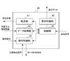
- FIG. 1is a block diagram showing one configuration example of a robot control system including a robot control device according to the first embodiment of the present disclosure.
- the robot control system 10includes a PLC 20, a robot teaching operation panel 30, a robot control device 40 and a robot 50.
- the robot controller 40is connected to the PLC 20 , the robot teaching operation panel 30 and the robot 50 .
- the robot teaching console 30may be provided as part of the robot controller 40 .
- the PLC 20defines the order of assembly work and the like performed by the robot 50 and outputs operation commands to the robot control device 40 .
- the robot control device 40controls the robot 50 based on the motion command.
- Robot controller 40transfers the current position of robot 50 to PLC 20 .
- PLC 20stores its current position within PLC 20 and controls robot 50 via robot controller 40 based on its current position.
- the PLC 20is prepared with a position array (predetermined area) as an area for storing the current position of the robot 50 .
- the PLC 20changes the input current position from the position stored in POS[3] of the position array of the PLC 20 to POS of the position array of the PLC 20. Overwrite the input current position with the position stored in [3].
- the robot teaching operation panel 30is a device having a display function and an information input function, such as a liquid crystal display device with a touch panel, a liquid crystal display device and a keyboard.
- the robot teaching console 30has a screen 31 .
- This screen 31has a position index number as a setting item, and which position array element of the PLC 20 is to be stored is designated by the position index number. Further, the screen 31 displays the current position of the robot 50, the position (PLC position) stored in the designated position array element of the PLC 20, and the like.
- This PLC positionis the same value as the position stored in POS[3] of the PLC 20 position array. Therefore, the user can confirm that the current position of the robot 50 is correctly stored in POS[3] of the position array of the PLC 20 by looking at the screen of the robot teaching console 30 .
- the useruses the robot teaching operation panel 30 to issue an instruction to transfer the current position of the robot 50 to the PLC 20 and an instruction to acquire from the PLC 20 the position stored in the PLC 20 or related information related to the position.
- the robot teaching operation panel 30outputs these instructions to the robot control device 40 as operation signals.
- the robot 50is, for example, an articulated robot, and includes a robot mechanism section 51 and an end factor 52 attached to the tip of the robot mechanism section 51 .
- the current position of the robot 50is, for example, the position of the end factor 52 attached to the tip of the robot mechanism section 51 of the robot 50 .
- the robot mechanism section 51has a plurality of joint shafts, for example, six joint shafts in FIG. Each joint shaft is provided with a motor. End factors 52 are, for example, robot hands, welding torches, paint sprayers, and the like.
- Each motoris provided with a position detector, such as an encoder. A position detection signal from the position detection unit of each joint axis is sent to the robot controller 40 .
- the robot control device 40controls each motor of a plurality of joint shafts of the robot mechanism section 51 based on motion commands from the PLC 20 . Further, the robot control device 40 obtains the values of the current position (X, Y, Z, W, P, R) of the robot 50 from the position detection signal output from the robot mechanism section 51 of the robot 50, and performs robot teaching operation. The values of the position (X, Y, Z, W, P, R) are displayed on the screen 31 of the board 30 as the current position.
- FIG. 2is a block diagram showing the configuration of the robot controller.
- the robot control device 40includes a transfer section 41 , a data acquisition section 42 , an operation control section 43 , a control section 44 and a display control section 45 .
- the motion control unit 43Based on the motion command from the PLC 20, the motion control unit 43 outputs a motor control command to the robot 50 for each motor in order to control each motor of a plurality of joint axes of the robot mechanism unit 51 of the robot 50. . Further, the motion control section 43 outputs the position detection signal of the position detection section of each joint axis to the control section 44 .
- the control unit 44obtains the values of the current position (X, Y, Z, W, P, R) of the robot 50 based on the position detection signals of the position detection units for each joint axis, and stores the current position. Output to the display control unit 45 . Further, when the operation signal received from the robot teaching operation panel 30 is an operation signal for transferring the current position of the robot 50 to the PLC 20, the control unit 44 outputs the stored current position to the transfer unit 41 together with a transfer instruction. . When the operation signal received from the robot teaching operation panel 30 is an operation signal for acquiring the position or the information related to the position stored in the PLC 20 from the PLC 20, the control unit 44 causes the data acquisition unit 42 to acquire data. Output instructions. The display control unit 45 displays the values of the position (X, Y, Z, W, P, R) as the current position on the screen 31 of the robot teaching console 30 .
- the robot control device 40includes an arithmetic processing device such as a CPU (Central Processing Unit).
- the robot control device 40also includes an auxiliary storage device such as a HDD (Hard Disk Drive) that stores various control programs such as application software and an OS (Operating System), and a temporary storage device for the arithmetic processing unit to execute programs. It also has a main storage device such as a random access memory (RAM) for storing the data that is actually needed.
- arithmetic processing devicesuch as a CPU (Central Processing Unit).
- the robot control device 40also includes an auxiliary storage device such as a HDD (Hard Disk Drive) that stores various control programs such as application software and an OS (Operating System), and a temporary storage device for the arithmetic processing unit to execute programs. It also has a main storage device such as a random access memory (RAM) for storing the data that is actually needed.
- RAMrandom access memory
- the arithmetic processing unitreads the application software and the OS from the auxiliary storage device, develops the read application software or OS in the main storage device, and performs arithmetic processing based on the application software or OS. do Also, based on the result of this calculation, various hardware included in each device is controlled. This implements the functional blocks of the robot control device 40 of the present embodiment. In other words, this embodiment can be realized by cooperation of hardware and software.
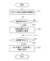
- FIG. 3is a flow chart showing the operation of the robot control device 40.
- FIG. 4is a diagram showing changes in the display information on the screen of the robot teaching console 30 and the stored information on the position array of the PLC 20. As shown in FIG.
- the display information on the screen 31 at this timeis assumed to be display information 30A.
- the stored information at this timeis referred to as stored information 20A.
- the display information on the screen 31changes from the display information 30A to the display information 30B.
- step S12the robot control device 40 detects whether or not the user has performed a transfer operation on the robot teaching operation panel 30.
- the transfer operationis performed, for example, by the user pressing a transfer key (not shown) of the liquid crystal display device with a touch panel of the robot teaching console 30 . If the transfer operation has been performed, the process moves to step S13, and if the transfer operation has not been performed, the process waits until the transfer operation is performed.
- the stored informationchanges from the stored information 20A to the stored information 20B.
- step S14the robot control device 40 detects whether or not the user has performed an operation to acquire the position data of the PLC of the robot teaching console 30.
- the position data acquisition operationis performed, for example, by the user selecting the position index [3] of the liquid crystal display device with a touch panel of the robot teaching console 30 and pressing a confirmation key (not shown). If the position data acquisition operation has been performed, the process proceeds to step S15, and if the position data acquisition operation has not been performed, the process waits until the position data acquisition operation is performed.
- the display information on the screen 31changes from display information 30B to display information 30C.
- the usercan confirm that the current position of the robot has been correctly stored in the position array of the PLC 20 by looking at the screen 31 of the robot teaching console 30 .
- the robot teaching operation panel 30to transfer the current position of the robot to the PLC 20, it is not necessary to confirm on the screen of the PLC 20 whether or not the position has been stored.
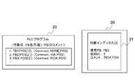
- FIG. 5is a diagram showing display information on the screen of the robot teaching console 30 and information stored in the PLC 20.
- the position array element in the PLC 20the name of the PLC function block (FB) referring to POS [3]
- the FBis acquired from the PLC 20 and displayed on the screen 31 of the robot teaching console 30 . It can be seen, for example, that this location is referenced by an FB named "FB3", and that "FB3" is taught in line 3 of the PLC program. If a comment or the like is attached to the FB, it is also displayed on this screen.
- "PICK_POSwhich means the picking position of the robot, is displayed as a comment.
- the robot controller 40transfers the current position of the robot 50 to the PLC 20, and the PLC 20 transfers POS[3] of the position array. ] overwrites the current position transferred from the robot controller 40 .
- the PLC 20before the PLC 20 overwrites the current position transferred from the robot controller 40 with the position stored in POS[3] of the position array, the PLC 20 asks the user for permission to overwrite.
- the control unit 44 of the robot control device 40receives an operation signal when the user performs an operation to transfer the current position of the robot to the PLC 20 on the screen 31 of the robot teaching operation panel 30 .
- the control unit 44displays a confirmation pop-up 30D with a message "Do you want to overwrite this position?" indicate.
- FIG. 6is a diagram showing a confirmation popup displayed on the screen 31. As shown in FIG. If the user selects "yes”, this position array element can be overwritten by transferring the current position. If the user selects "no", the transfer is aborted and the positions of the PLC 20 position array elements are not changed.
- FIG. 7is a flow chart showing the operation of the robot control device 40 of the third embodiment.
- the flowchart of FIG. 7has three steps S21, S22 and S23 between steps S12 and S13 of the flowchart of FIG.
- step S12the robot control device 40 detects whether or not the transfer operation of the robot teaching console 30 has been performed by the user, and when the transfer operation has been performed, the process proceeds to step S21.
- the robot controller 40acquires the position data stored in the position array elements of the PLC and determines whether all of the position data are "0".
- the position data of the robotincludes not only X, Y, Z, W, P, and R, but also the posture, and even if X, Y, Z, W, P, and R are "0", the posture value is included.
- the position dataare not all "0". Since the initial values of the position data stored in the position array elements of the PLC are all "0", it can be determined that the transfer process is not performed when the position data are all "0". Therefore, when the position data are all "0", the robot control device 40 does not display the confirmation pop-up 30D on the screen because it is the first transfer, and proceeds to step S13.
- the robot control device 40displays a confirmation pop-up 30D on the screen 31 of the robot teaching operation panel 30, and proceeds to step S23. If the user selects "Yes” in step 23, the robot controller 40 proceeds to step S13. If the user selects "no", no transfer takes place and the position of the PLC 20 position array element is not changed.
- each component included in the robot control devicecan be realized by hardware, software, or a combination thereof. Further, a robot control method performed by cooperation of each component included in the robot control device can also be realized by hardware, software, or a combination thereof.
- “implemented by software”means implemented by a computer reading and executing a program.
- Non-transitory computer-readable storage mediainclude various types of tangible storage media.
- Examples of non-transitory computer-readable recording mediainclude magnetic recording media (e.g., hard disk drives), magneto-optical recording media (e.g., magneto-optical discs), CD-ROM (Read Only Memory), CD-R, CD - R/W, including semiconductor memory (eg Mask ROM, PROM (Programmable ROM), EPROM (Erasable PROM), Flash ROM, RAM (random access memory)).
- the robot control device, robot control system, and robot control method according to the present disclosurecan take various embodiments having the following configurations, including the embodiments described above.
- a robot control devicee.g., robot control device 40 that is connected to a programmable logic controller (e.g., PLC 20) and controls a robot (e.g., robot 50), a transfer unit (e.g., transfer unit 41) for transferring the current position of the robot to the programmable logic controller in order to store the current position of the robot in a predetermined area in the programmable logic controller; an acquisition unit (for example, a data acquisition unit 42) that acquires the current position stored in the programmable logic controller or information related to the current position from the programmable logic controller; a display control unit (for example, a display control unit 45) that displays the acquired current position or the related information on the screen of the robot teaching operation panel (for example, the robot teaching operation panel 30); A robot controller with According to this robot control device, when transferring the current position of the robot to the PLC and storing it, there is no need to alternately perform the transfer operation on the robot teaching operation panel and the confirmation operation on the PLC screen. Operation can be completed
- the acquisition unitacquires information on the function block, and the display control unit
- a robot control systemcomprising the robot control device (eg, robot control device) according to any one of (1) to (4) above, and a programmable logic controller connected to the robot control device.
- the robot control deviceeg, robot control device
- a programmable logic controllerconnected to the robot control device.
- the robot control deviceacquires the current position stored in the programmable logic controller or information related to the current position from the programmable logic controller,
- robot control system20 PLC 30 robot teaching operation panel 40 robot control device 41 transfer unit 42 data acquisition unit 43 motion control unit 44 control unit 45 display control unit 50 robot 51 robot mechanism unit 52 end factor
Landscapes
- Engineering & Computer Science (AREA)
- Robotics (AREA)
- Mechanical Engineering (AREA)
- Physics & Mathematics (AREA)
- General Physics & Mathematics (AREA)
- Automation & Control Theory (AREA)
- Numerical Control (AREA)
- Manipulator (AREA)
Abstract
Description
Translated fromJapanese本発明は、ロボット制御装置、ロボット制御システム及びロボット制御方法に関し、特に、プログラマブルロジックコントローラ(以下、PLCと記す)と接続され、ロボットを制御するロボット制御装置、ロボット制御システム及びロボット制御方法に関する。The present invention relates to a robot control device, a robot control system, and a robot control method, and more particularly to a robot control device, a robot control system, and a robot control method that are connected to a programmable logic controller (hereinafter referred to as PLC) and control a robot.
近年、PLCopenの規格に代表されるように、PLCプログラムでロボットを動作させるシステムが普及しつつある。PLCからロボットを動作させるためには、ロボット制御装置がロボットの現在位置をPLCに転送し、PLCがその現在位置をPLC内に格納しておく必要がある。
ユーザは、ロボット教示操作盤を操作してロボットの現在位置をPLCへ転送した後、PLCの画面でその現在位置が格納されたかどうかを確認するといった作業が求められる。In recent years, as typified by the PLCopen standard, systems that operate robots with PLC programs are becoming widespread. In order to operate the robot from the PLC, the robot controller must transfer the robot's current position to the PLC, which must store the current position in the PLC.
After transferring the current position of the robot to the PLC by operating the robot teaching operation panel, the user is required to confirm whether the current position has been stored on the screen of the PLC.
PLC及びロボット制御装置を含むシステムは、例えば特許文献1に記載されている。
特許文献1には、ロボットと周辺機器を組み合わせたシステム全体の動作シミュレーションができるロボットシミュレーション装置が記載されている。ロボットシミュレーション装置においては、PCがロボット識別情報によって、ロボットを指定し、指定したロボット制御装置が教示動作プログラムを読み込みPCのメモリ内に格納する。次に、ロボット識別情報で指定したロボット制御装置によって、動作プログラムが実行されると共に、PLCでロボット識別情報に対応するシーケンスプログラムが実行され、溶接機等の周辺機器とのI/OデータがPCに取り込まれ、制御履歴が記憶される。そして、ロボット制御装置からの情報と、PLCからの情報とに基づいて、ロボットアニメーションがPCのグラフィックディスプレイ装置の表示画面上に表示され、また、周辺機器の動作状態情報が表示される。A system including a PLC and a robot controller is described, for example, in US Pat.
ユーザが、ロボット教示操作盤を操作して、ロボットの現在位置をPLCに転送して格納する際に、ユーザは、ロボット教示操作盤での転送操作とPLCの画面での確認操作とを交互に行う必要があり、時間がかかるという課題があった。When the user operates the robot teaching operation panel to transfer the current position of the robot to the PLC and store it, the user alternates between the transfer operation on the robot teaching operation panel and the confirmation operation on the PLC screen. There was a problem that it was necessary to do it and it took time.
(1) 本開示の第1の態様は、プログラマブルロジックコントローラと接続され、ロボットを制御するロボット制御装置であって、
前記ロボットの現在位置を前記プログラマブルロジックコントローラ内の所定の領域に格納するために、該現在位置を前記プログラマブルロジックコントローラへ転送する転送部と、
前記プログラマブルロジックコントローラに格納された前記現在位置又は前記現在位置の関連情報を前記プログラマブルロジックコントローラから取得する取得部と、
取得した前記現在位置又は前記関連情報を、ロボット教示操作盤の画面に表示する表示制御部と、
を備えたロボット制御装置である。(1) A first aspect of the present disclosure is a robot control device that is connected to a programmable logic controller and controls a robot,
a transfer unit for transferring the current position of the robot to the programmable logic controller in order to store the current position of the robot in a predetermined area in the programmable logic controller;
an acquisition unit that acquires the current position stored in the programmable logic controller or information related to the current position from the programmable logic controller;
a display control unit that displays the acquired current position or the related information on a screen of a robot teaching operation panel;
It is a robot control device with
(2) 本開示の第2の態様は、上記(1)に記載のロボット制御装置と、該ロボット制御装置と接続されるプログラマブルロジックコントローラとを備えた、ロボット制御システムである。(2) A second aspect of the present disclosure is a robot control system comprising the robot control device described in (1) above and a programmable logic controller connected to the robot control device.
(3) 本開示の第3の態様は、プログラマブルロジックコントローラと、該プログラマブルロジックコントローラと接続されるロボット制御装置とを用いて、ロボットを制御するロボット制御方法において、
前記ロボットの現在位置を前記プログラマブルロジックコントローラ内の所定の領域に格納するために、前記ロボット制御装置が該現在位置を前記プログラマブルロジックコントローラへ転送し、
前記ロボット制御装置が、前記プログラマブルロジックコントローラに格納された前記現在位置又は前記現在位置の関連情報を前記プログラマブルロジックコントローラから取得し、
前記ロボット制御装置が、取得した前記現在位置又は前記関連情報を、ロボット教示操作盤の画面に表示する、ロボット制御方法である。(3) A third aspect of the present disclosure is a robot control method for controlling a robot using a programmable logic controller and a robot control device connected to the programmable logic controller,
the robot controller transferring the current position of the robot to the programmable logic controller to store the current position of the robot in a predetermined area in the programmable logic controller;
The robot control device acquires the current position stored in the programmable logic controller or information related to the current position from the programmable logic controller,
In the robot control method, the robot control device displays the acquired current position or the related information on a screen of a robot teaching operation panel.
本開示の各態様によれば、ロボットの現在位置をPLCに転送して格納する際に、ロボット教示操作盤での転送操作とPLCの画面での確認操作とを交互に行う必要がなくなり、一連の操作をロボット教示操作盤だけで済ませることができる。According to each aspect of the present disclosure, when transferring and storing the current position of the robot to the PLC, there is no need to alternately perform the transfer operation on the robot teaching operation panel and the confirmation operation on the PLC screen, and a series of can be completed with only the robot teaching operation panel.
以下、本発明の実施形態について図面を用いて詳細に説明する。
(第1実施形態)
図1は本開示の第1実施形態のロボット制御装置を含むロボット制御システムの一構成例を示すブロック図である。BEST MODE FOR CARRYING OUT THE INVENTION Hereinafter, embodiments of the present invention will be described in detail with reference to the drawings.
(First embodiment)
FIG. 1 is a block diagram showing one configuration example of a robot control system including a robot control device according to the first embodiment of the present disclosure.
図1に示すように、ロボット制御システム10は、PLC20、ロボット教示操作盤30、ロボット制御装置40及びロボット50を備えている。
ロボット制御装置40は、PLC20、ロボット教示操作盤30、及びロボット50に接続されている。ロボット教示操作盤30は、ロボット制御装置40の一部として設けられてもよい。
PLC20は、ロボット50が行う組立作業等の順序を規定し、ロボット制御装置40に動作指令を出力する。ロボット制御装置40は、動作指令に基づいてロボット50を制御する。
ロボット制御装置40は、ロボット50の現在位置をPLC20に転送する。PLC20はその現在位置をPLC20内に格納し、その現在位置に基づいてロボット制御装置40を介してロボット50を制御する。As shown in FIG. 1, the
The
The
PLC20には、ロボット50の現在位置を格納する領域として位置配列(所定の領域となる)が用意されている。例えば、図1に示すように、PLC20の位置配列のPOS[3]には、ロボット50の現在位置として、X=30、Y=20、Z=15、W=0、P=0、R=0が格納されている。PLC20は、ロボット制御装置40からロボット50の現在位置が入力された場合、入力された現在位置が、PLC20の位置配列のPOS[3]に格納された位置と異なる場合、PLC20の位置配列のPOS[3]に格納された位置を入力された現在位置に上書きする。The
ロボット教示操作盤30は、表示機能と情報入力機能とを備えた装置で、例えばタッチパネル付き液晶表示装置、液晶表装置とキーボード等である。ロボット教示操作盤30は、画面31を備える。この画面31には、設定項目として位置インデックス番号があり、位置インデックス番号によってPLC20のどの位置配列要素に格納するかがを指定される。さらに、画面31には、ロボット50の現在位置及びPLC20の指定した位置配列要素に格納されている位置(PLC位置)などが表示される。The robot
例えば、図1には、ロボット教示操作盤30の画面31に、位置インデックス番号として位置インデックス[3]が表示され、ロボット50の現在位置として、X=30、Y=20、Z=15、W=0、P=0、R=0が表示される。また、ロボット教示操作盤30の画面に、PLC位置として、X=30、Y=20、Z=15、W=0、P=0、R=0が表示される。このPLC位置はPLC20の位置配列のPOS[3]に格納されている位置と同じ値である。このため、ユーザは、ロボット教示操作盤30の画面を見ることで、ロボット50の現在位置が、PLC20の位置配列のPOS[3]に正しく格納されたことを確認できる。For example, in FIG. 1, a position index [3] is displayed as a position index number on the
ユーザは、ロボット教示操作盤30を用いて、ロボット50の現在位置をPLC20へ転送する指示、及びPLC20から、PLC20に格納されている位置又は位置に関連する関連情報を取得する指示を行う。ロボット教示操作盤30はこれらの指示を操作信号としてロボット制御装置40に出力する。The user uses the robot
ロボット50は、例えば、多関節ロボットであり、ロボット機構部51、及びロボット機構部51の先端に取り付けられたエンドファクタ52を備えている。ロボット50の現在位置は、例えば、ロボット50のロボット機構部51の先端に取り付けられるエンドファクタ52の位置である。
ロボット機構部51は、複数の関節軸、例えば図1では6個の関節軸を有している。各関節軸にはそれぞれモータが設けられている。エンドファクタ52は、例えば、ロボットハンド、溶接トーチ、塗料噴霧器等である。モータのそれぞれには位置検出部、例えばエンコーダが設けられている。各関節軸の位置検出部の位置検出信号は、ロボット制御装置40に送られる。The
The
ロボット制御装置40は、PLC20からの動作指令に基づいて、ロボット機構部51の複数の関節軸の各モータをそれぞれ制御する。
また、ロボット制御装置40は、ロボット50のロボット機構部51から出力される位置検出信号から、ロボット50の現在位置(X,Y,Z,W,P,R)の値を求め、ロボット教示操作盤30の画面31に現在位置として位置(X,Y,Z,W,P,R)の値を表示する。The
Further, the
図2はロボット制御装置の構成を示すブロック図である。
図2に示すように、ロボット制御装置40は、転送部41、データ取得部42、動作制御部43、制御部44及び表示制御部45を備える。FIG. 2 is a block diagram showing the configuration of the robot controller.
As shown in FIG. 2 , the
転送部41は、制御部44から転送指示があった場合に、ロボット50の現在位置である、X=30、Y=20、Z=15、W=0、P=0、R=0をPLC20に転送する。
データ取得部42は、制御部44からデータ取得指示があった場合に、PLC20の位置配列のPOS[3]に格納された、X=30、Y=20、Z=15、W=0、P=0、R=0をPLC20から取得する。When there is a transfer instruction from the
When receiving a data acquisition instruction from the
動作制御部43は、PLC20からの動作指令に基づいて、ロボット50のロボット機構部51の複数の関節軸の各モータをそれぞれ制御するために、ロボット50にモータ制御指令を各モータごとに出力する。また、動作制御部43は、各関節軸の位置検出部の位置検出信号を制御部44に出力する。Based on the motion command from the
制御部44は、各関節軸の位置検出部の位置検出信号に基づいて、ロボット50の現在位置(X,Y,Z,W,P,R)の値を求め、現在位置を記憶するとともに、表示制御部45に出力する。
また、制御部44は、ロボット教示操作盤30から受けた操作信号が、ロボット50の現在位置をPLC20へ転送する操作信号である場合は、記憶した現在位置を転送部41に転送指示とともに出力する。制御部44は、ロボット教示操作盤30から受けた操作信号が、PLC20から、PLC20に格納されている位置又は位置に関連する情報を取得する操作信号である場合は、データ取得部42にデータ取得指示を出力する。
表示制御部45は、ロボット教示操作盤30の画面31に現在位置として位置(X,Y,Z,W,P,R)の値を表示する。The
Further, when the operation signal received from the robot
The
以上、ロボット制御装置40に含まれる機能ブロックについて説明した。
これらの機能ブロックを実現するために、ロボット制御装置40は、CPU(Central Processing Unit)等の演算処理装置を備える。また、ロボット制御装置40は、アプリケーションソフトウェア及びOS(Operating System)等の各種の制御用プログラムを格納したHDD(Hard Disk Drive)等の補助記憶装置や、演算処理装置がプログラムを実行する上で一時的に必要とされるデータを格納するためのRAM(Random Access Memory)といった主記憶装置も備える。The functional blocks included in the
In order to realize these functional blocks, the
そして、ロボット制御装置40において、演算処理装置が補助記憶装置からアプリケーションソフトウェアやOSを読み込み、読み込んだアプリケーションソフトウェア又はOSを主記憶装置に展開させながら、これらのアプリケーションソフトウェア又はOSに基づいた演算処理を行なう。また、この演算結果に基づいて、各装置が備える各種のハードウェアを制御する。これにより、本実施形態のロボット制御装置40の機能ブロックは実現される。つまり、本実施形態は、ハードウェアとソフトウェアが協働することにより実現することができる。In the
以下、ロボット50の現在位置が、X=30、Y=20、Z=15、W=30、P=20、R=15から、X=30、Y=20、Z=15、W=0、P=0、R=0に変わった場合のロボット制御装置40の動作について図3及び図4を用いて説明する。図3はロボット制御装置40の動作を示すフローチャートである。図4は、ロボット教示操作盤30の画面の表示情報と、PLC20の位置配列の格納情報との変化を示す図である。Below, the current position of the
図4に示すように、まず、ロボット教示操作盤30の画面31には、ロボット50の現在位置として、X=30、Y=20、Z=15、W=30、P=20、R=15が表示され、PLC位置として、X=30、Y=20、Z=15、W=30、P=20、R=15が表示されているとする。このときの画面31の表示情報を表示情報30Aとする。PLC20の位置配列のPOS[3]には、X=30、Y=20、Z=15、W=30、P=20、R=15が格納されている。このときの格納情報を格納情報20Aとする。As shown in FIG. 4, first, on the
ロボット制御装置40は、ロボット50のロボット機構部51の先端のエンドファクタ52の位置がX=30、Y=20、Z=15、W=0、P=0、R=0となるようにエンドファクタ52を回転させる。The
図3のステップS11において、ロボット制御装置40はロボット50からの位置検出信号に基づいて、図4に示すように、ロボット50の現行位置をX=30、Y=20、Z=15、W=30、P=20、R=15から、X=30、Y=20、Z=15、W=0、P=0、R=0に変更して、ロボット教示操作盤30の画面31に表示する。すると、画面31の表示情報は表示情報30Aから表示情報30Bに変わる。
ユーザは、画面31の表示情報30BのPLC位置を見て、PLC20の位置配列のPOS[3]には、X=30、Y=20、Z=15、W=30、P=20、R=15が格納されたままであることを認識する。At step S11 in FIG. 3, the
The user sees the PLC position of the
ステップS12において、ロボット制御装置40はユーザによって、ロボット教示操作盤30の転送操作が行われたかどうかを検出する。転送操作は、例えばロボット教示操作盤30のタッチパネル付液晶表示装置の不図示の転送キーがユーザによって押されることで行われる。転送操作が行われた場合はステップS13に移り、転送操作が行われていない場合には転送操作が行われるまで待機する。In step S12, the
ステップS13において、ロボット制御装置40は、現在位置である、X=30、Y=20、Z=15、W=0、P=0、R=0をPLC20に転送する。PLC20は、位置配列のPOS[3]に格納された、X=30、Y=20、Z=15、W=30、P=20、R=15を、X=30、Y=20、Z=15、W=0、P=0、R=0に上書きする。すると、格納情報は格納情報20Aから格納情報20Bとなる。In step S13, the
ステップS14において、ロボット制御装置40はユーザによって、ロボット教示操作盤30のPLCの位置データ取得操作が行われたかどうかを検出する。位置データ取得操作は、例えばユーザがロボット教示操作盤30のタッチパネル付液晶表示装置の位置インデックス[3]を選択し、不図示の確認キーを押すことで行われる。位置データ取得操作が行われた場合はステップS15に移り、位置データ取得操作が行われていない場合には位置データ取得操作が行われるまで待機する。In step S14, the
ステップS15において、ロボット制御装置40は、PLC20の位置配列のPOS[3]に格納された、X=30、Y=20、Z=15、W=0、P=0、R=0を取得する。そして、ロボット制御装置40は、ロボット教示操作盤30の画面31のPLC位置をX=30、Y=20、Z=15、W=0、P=0、R=0に変更する。画面31の表示情報は表示情報30Bから表示情報30Cに変わる。In step S15, the
ユーザはロボット教示操作盤30の表示情報30Cを見て、PLC20の位置配列のPOS[3]には、X=30、Y=20、Z=15、W=0、P=0、R=0が上書きされて格納されたことを認識する。The user sees the
以上の動作により、ユーザは、ロボット教示操作盤30の画面31を見ることで、ロボットの現在位置がPLC20の位置配列に正しく格納されたことを確認することができる。その結果、ユーザが、ロボット教示操作盤30を操作してロボットの現在位置をPLC20へ転送した後、PLC20の画面でその位置が格納されたかどうかを確認するといった作業は不要となる。Through the above operations, the user can confirm that the current position of the robot has been correctly stored in the position array of the
(第2実施形態)
第1実施形態では、ユーザがロボット教示操作盤30の不図示の確認キーを押すことで、PLC20の位置配列のPOS[3]に格納された、PLC位置を取得して、ロボット教示操作盤30にPLC位置を表示した。
本実施形態では、ユーザがロボット教示操作盤30の不図示の確認キーを押すことで、PLC20に格納されている、位置の関連情報がPLC20から取得され、ロボット教示操作盤30の画面31に表示される。位置の関連情報は、例えば、PLCに格納されたロボットの位置を参照しているPLCのファンクションブロック(FB)の名称、そのFBが教示されているPLCプログラムの行番号、及びFBのコメントなどである。(Second embodiment)
In the first embodiment, when the user presses a confirmation key (not shown) of the robot
In this embodiment, when the user presses a confirmation key (not shown) of the robot
図5は、ロボット教示操作盤30の画面の表示情報と、PLC20の格納情報とを示す図である。
例えば、ユーザが位置インデックス[3]を選択し、不図示の確認キーを押すと、PLC20内の位置配列要素:POS[3]を参照しているPLCのファンクションブロック(FB)の名称、そのFBが教示されているPLCプログラムの行番号、及びFBのコメントがPLC20から取得され、ロボット教示操作盤30の画面31に表示される。それによって、例えば、この位置は「FB3」という名称のFBで参照されていること、及びこの「FB3」はPLCプログラムの3行目に教示されていることなどが分かる。FBにコメントなどが付けられている場合は、それもこの画面に表示される。図5では、コメントとして、ロボットのピッキング位置を意味する“PICK_POS”が表示される。FIG. 5 is a diagram showing display information on the screen of the
For example, when the user selects the position index [3] and presses a confirmation key (not shown), the position array element in the PLC 20: the name of the PLC function block (FB) referring to POS [3], the FB is acquired from the
(第3実施形態)
第1実施形態では、ユーザが、ロボット教示操作盤30の不図示の転送キーを押すと、ロボット制御装置40は、ロボット50の現在位置をPLC20に転送し、PLC20は、位置配列のPOS[3]に格納された位置をロボット制御装置40から転送された現在の位置に上書きしていた。
本実施形態では、PLC20は、位置配列のPOS[3]に格納された位置をロボット制御装置40から転送された現在の位置に上書きする前に、ユーザに上書きの可否を求めるようにする。(Third embodiment)
In the first embodiment, when the user presses a transfer key (not shown) of the
In this embodiment, before the
ロボット制御装置40の制御部44は、ユーザによって、ロボット教示操作盤30の画面31上でロボットの現在位置をPLC20に転送する操作がされると、操作信号を受ける。制御部44は、操作信号を受けた際に、指定した位置配列要素に既に位置が格納されている場合は、「この位置を上書きしますか?」というメッセージの確認用ポップアップ30Dを画面31に表示する。図6は、画面31に表示された確認用ポップアップを示す図である。ユーザが「はい」を選択した場合、この位置配列要素に現在位置を転送して上書きすることができる。ユーザが「いいえ」を選択した場合、転送は中断されPLC20の位置配列要素の位置は変更されない。The
図7は第3実施形態のロボット制御装置40の動作を示すフローチャートである。
図7のフローチャートは、図3のフローチャートのステップS12とステップS13との間に、3つのステップS21、S22及びS23が設けられている。
ステップS12において、ロボット制御装置40はユーザによって、ロボット教示操作盤30の転送操作が行われたかどうかを検出し、転送操作が行われた場合はステップS21に移る。FIG. 7 is a flow chart showing the operation of the
The flowchart of FIG. 7 has three steps S21, S22 and S23 between steps S12 and S13 of the flowchart of FIG.
In step S12, the
ステップ21において、ロボット制御装置40は、PLCの位置配列要素に格納されている位置データを取得し、その位置データが全て“0”であるかどうかを判断する。ロボットの位置データは、X、Y、Z、W、P及びRの他に姿勢も含まれており、X、Y、Z、W、P及びRが“0”でも姿勢の値が入るため、位置データは全て“0”にならない。
PLCの位置配列要素に格納されている位置データの初期値は全て“0”であるため、位置データが全て“0”である場合は、転送処理は行われていないと判断できる。そこで、ロボット制御装置40は、位置データが全て“0”である場合は、初回の転送であるため、確認用ポップアップ30Dを画面に表示せず、ステップS13に移り、ロボット制御装置40は、現在位置である、X=30、Y=20、Z=15、W=0、P=0、R=0をPLC20に転送する。
一方、ロボット制御装置40は、位置データが全て“0”でない場合は、転送処理が既に行われていると判断し、ステップS22に移る。At step 21, the
Since the initial values of the position data stored in the position array elements of the PLC are all "0", it can be determined that the transfer process is not performed when the position data are all "0". Therefore, when the position data are all "0", the
On the other hand, if all the position data are not "0", the
ステップ22において、ロボット制御装置40は、確認用ポップアップ30Dをロボット教示操作盤30の画面31に表示し、ステップS23に移る。
ステップ23において、ユーザが「はい」を選択した場合、ロボット制御装置40はステップS13に移る。ユーザが「いいえ」を選択した場合、転送は行われず、PLC20の位置配列要素の位置は変更されない。At step S22, the
If the user selects "Yes" in step 23, the
以上本発明に係る各実施形態について説明したが、ロボット制御装置に含まれる各構成部は、ハードウェア、ソフトウェア又はこれらの組み合わせにより実現することができる。また、ロボット制御装置に含まれる各構成部のそれぞれの協働により行なわれるロボット制御方法も、ハードウェア、ソフトウェア又はこれらの組み合わせにより実現することができる。ここで、ソフトウェアによって実現されるとは、コンピュータがプログラムを読み込んで実行することにより実現されることを意味する。Although each embodiment according to the present invention has been described above, each component included in the robot control device can be realized by hardware, software, or a combination thereof. Further, a robot control method performed by cooperation of each component included in the robot control device can also be realized by hardware, software, or a combination thereof. Here, "implemented by software" means implemented by a computer reading and executing a program.
プログラムは、様々なタイプの非一時的なコンピュータ読み取り可能な記録媒体(non-transitory computer readable medium)を用いて格納され、コンピュータに供給することができる。非一時的なコンピュータ読み取り可能な記録媒体は、様々なタイプの実体のある記録媒体(tangible storage medium)を含む。非一時的なコンピュータ読み取り可能な記録媒体の例は、磁気記録媒体(例えば、ハードディスクドライブ)、光磁気記録媒体(例えば、光磁気ディスク)、CD-ROM(Read Only Memory)、CD-R、CD-R/W、半導体メモリ(例えば、マスクROM、PROM(Programmable ROM)、EPROM(Erasable PROM)、フラッシュROM、RAM(random access memory))を含む。Programs can be stored and supplied to computers using various types of non-transitory computer readable media. Non-transitory computer-readable storage media include various types of tangible storage media. Examples of non-transitory computer-readable recording media include magnetic recording media (e.g., hard disk drives), magneto-optical recording media (e.g., magneto-optical discs), CD-ROM (Read Only Memory), CD-R, CD - R/W, including semiconductor memory (eg Mask ROM, PROM (Programmable ROM), EPROM (Erasable PROM), Flash ROM, RAM (random access memory)).
上述した実施形態は、本発明の好適な実施形態ではあるが、上記実施形態のみに本発明の範囲を限定するものではなく、本発明の要旨を逸脱しない範囲において種々の変更を施した形態での実施が可能である。The above-described embodiments are preferred embodiments of the present invention, but the scope of the present invention is not limited only to the above-described embodiments, and various modifications can be made without departing from the scope of the present invention. can be implemented.
本開示によるロボット制御装置、ロボット制御システム及びロボット制御方法は、上述した実施形態を含め、次のような構成を有する各種各様の実施形態を取ることができる。The robot control device, robot control system, and robot control method according to the present disclosure can take various embodiments having the following configurations, including the embodiments described above.
(1) プログラマブルロジックコントローラ(例えば、PLC20)と接続され、ロボット(例えば、ロボット50)を制御するロボット制御装置(例えば、ロボット制御装置40)であって、
前記ロボットの現在位置を前記プログラマブルロジックコントローラ内の所定の領域に格納するために、該現在位置を前記プログラマブルロジックコントローラへ転送する転送部(例えば、転送部41)と、
前記プログラマブルロジックコントローラに格納された前記現在位置又は前記現在位置の関連情報を前記プログラマブルロジックコントローラから取得する取得部(例えば、データ取得部42)と、
取得した前記現在位置又は前記関連情報を、ロボット教示操作盤(例えば、ロボット教示操作盤30)の画面に表示する表示制御部(例えば、表示制御部45)と、
を備えたロボット制御装置。
このロボット制御装置によれば、ロボットの現在位置をPLCに転送して格納する際に、ロボット教示操作盤での転送操作とPLCの画面での確認操作とを交互に行う必要がなくなり、一連の操作をロボット教示操作盤だけで済ませることができる。(1) A robot control device (e.g., robot control device 40) that is connected to a programmable logic controller (e.g., PLC 20) and controls a robot (e.g., robot 50),
a transfer unit (e.g., transfer unit 41) for transferring the current position of the robot to the programmable logic controller in order to store the current position of the robot in a predetermined area in the programmable logic controller;
an acquisition unit (for example, a data acquisition unit 42) that acquires the current position stored in the programmable logic controller or information related to the current position from the programmable logic controller;
a display control unit (for example, a display control unit 45) that displays the acquired current position or the related information on the screen of the robot teaching operation panel (for example, the robot teaching operation panel 30);
A robot controller with
According to this robot control device, when transferring the current position of the robot to the PLC and storing it, there is no need to alternately perform the transfer operation on the robot teaching operation panel and the confirmation operation on the PLC screen. Operation can be completed only with the robot teaching operation panel.
(2) 前記プログラマブルロジックコントローラに格納された前記現在位置が、プログラマブルロジックコントローラプログラム内のファンクションブロックで参照されている場合、前記取得部は、該ファンクションブロックの情報を取得し、前記表示制御部は前記ロボット教示操作盤の画面に表示する、上記(1)に記載のロボット制御装置。(2) When the current position stored in the programmable logic controller is referenced by a function block in the programmable logic controller program, the acquisition unit acquires information on the function block, and the display control unit The robot control device according to (1) above, which is displayed on the screen of the robot teaching console.
(3) 前記現在位置を前記プログラマブルロジックコントローラに転送する場合、前記所定の領域に既に前記現在位置が格納されている場合、それを上書きするかどうかを確認するポップアップを前記ロボット教示操作盤の画面に表示する、上記(1)又は(2)に記載のロボット制御装置。(3) When transferring the current position to the programmable logic controller, if the current position is already stored in the predetermined area, a pop-up to confirm whether to overwrite it is displayed on the screen of the robot teaching operation panel. The robot control device according to (1) or (2) above, wherein
(4) 前記ロボット教示操作盤を含む、上記(1)から(3)のいずれかに記載のロボット制御装置。(4) The robot control device according to any one of (1) to (3) above, including the robot teaching operation panel.
(5) 上記(1)から(4)のいずれかに記載のロボット制御装置(例えば、ロボット制御装置)と、該ロボット制御装置と接続されるプログラマブルロジックコントローラとを備えた、ロボット制御システム。
このロボット制御システムによれば、ロボットの現在位置をPLCに転送して格納する際に、ロボット教示操作盤での転送操作とPLCの画面での確認操作とを交互に行う必要がなくなり、一連の操作をロボット教示操作盤だけで済ませることができる。(5) A robot control system comprising the robot control device (eg, robot control device) according to any one of (1) to (4) above, and a programmable logic controller connected to the robot control device.
According to this robot control system, when transferring and storing the current position of the robot to the PLC, there is no need to alternately perform the transfer operation on the robot teaching operation panel and the confirmation operation on the PLC screen. Operation can be completed only with the robot teaching operation panel.
(6) プログラマブルロジックコントローラ(例えば、PLC20)と、該プログラマブルロジックコントローラと接続されるロボット制御装置(例えば、ロボット制御装置40)とを用いて、ロボットを制御するロボット制御方法において、
前記ロボットの現在位置を前記プログラマブルロジックコントローラ内の所定の領域に格納するために、前記ロボット制御装置が該現在位置を前記プログラマブルロジックコントローラへ転送し、
前記ロボット制御装置が、前記プログラマブルロジックコントローラに格納された前記現在位置又は前記現在位置の関連情報を前記プログラマブルロジックコントローラから取得し、
前記ロボット制御装置が、取得した前記現在位置又は前記関連情報を、ロボット教示操作盤の画面に表示する、ロボット制御方法。
このロボット制御方法によれば、ロボットの現在位置をPLCに転送して格納する際に、ロボット教示操作盤での転送操作とPLCの画面での確認操作とを交互に行う必要がなくなり、一連の操作をロボット教示操作盤だけで済ませることができる。(6) A robot control method for controlling a robot using a programmable logic controller (eg, PLC 20) and a robot control device (eg, robot control device 40) connected to the programmable logic controller,
the robot controller transferring the current position of the robot to the programmable logic controller to store the current position of the robot in a predetermined area in the programmable logic controller;
The robot control device acquires the current position stored in the programmable logic controller or information related to the current position from the programmable logic controller,
A robot control method, wherein the robot control device displays the obtained current position or the related information on a screen of a robot teaching operation panel.
According to this robot control method, when transferring the current position of the robot to the PLC and storing it, there is no need to alternately perform the transfer operation on the robot teaching operation panel and the confirmation operation on the PLC screen. Operation can be completed only with the robot teaching operation panel.
10 ロボット制御システム
20 PLC
30 ロボット教示操作盤
40 ロボット制御装置
41 転送部
42 データ取得部
43 動作制御部
44 制御部
45 表示制御部
50 ロボット
51 ロボット機構部
52 エンドファクタ10
30 robot
Claims (6)
Translated fromJapanese前記ロボットの現在位置を前記プログラマブルロジックコントローラ内の所定の領域に格納するために、該現在位置を前記プログラマブルロジックコントローラへ転送する転送部と、
前記プログラマブルロジックコントローラに格納された前記現在位置又は前記現在位置の関連情報を前記プログラマブルロジックコントローラから取得する取得部と、
取得した前記現在位置又は前記関連情報を、ロボット教示操作盤の画面に表示する表示制御部と、
を備えたロボット制御装置。A robot control device connected to a programmable logic controller and controlling a robot,
a transfer unit for transferring the current position of the robot to the programmable logic controller in order to store the current position of the robot in a predetermined area in the programmable logic controller;
an acquisition unit that acquires the current position stored in the programmable logic controller or information related to the current position from the programmable logic controller;
a display control unit that displays the acquired current position or the related information on a screen of a robot teaching operation panel;
A robot controller with
前記ロボットの現在位置を前記プログラマブルロジックコントローラ内の所定の領域に格納するために、前記ロボット制御装置が該現在位置を前記プログラマブルロジックコントローラへ転送し、
前記ロボット制御装置が、前記プログラマブルロジックコントローラに格納された前記現在位置又は前記現在位置の関連情報を前記プログラマブルロジックコントローラから取得し、
前記ロボット制御装置が、取得した前記現在位置又は前記関連情報を、ロボット教示操作盤の画面に表示する、ロボット制御方法。In a robot control method for controlling a robot using a programmable logic controller and a robot control device connected to the programmable logic controller,
the robot controller transferring the current position of the robot to the programmable logic controller to store the current position of the robot in a predetermined area in the programmable logic controller;
The robot control device acquires the current position stored in the programmable logic controller or information related to the current position from the programmable logic controller,
A robot control method, wherein the robot control device displays the obtained current position or the related information on a screen of a robot teaching operation panel.
Priority Applications (6)
| Application Number | Priority Date | Filing Date | Title |
|---|---|---|---|
| CN202180096197.1ACN117043692A (en) | 2021-04-01 | 2021-04-01 | Robot control device, robot control system, and robot control method |
| JP2023510118AJP7572542B2 (en) | 2021-04-01 | 2021-04-01 | ROBOT CONTROL DEVICE, ROBOT CONTROL SYSTEM, AND ROBOT CONTROL METHOD |
| PCT/JP2021/014184WO2022208849A1 (en) | 2021-04-01 | 2021-04-01 | Robot control device, robot control system, and robot control method |
| US18/276,996US20240116191A1 (en) | 2021-04-01 | 2021-04-01 | Robot control device, robot control system, and robot control method |
| DE112021006836.9TDE112021006836T5 (en) | 2021-04-01 | 2021-04-01 | Robot control device, robot control system and robot control method |
| TW111108411ATW202239547A (en) | 2021-04-01 | 2022-03-08 | Robot control device, robot control system, and robot control method |
Applications Claiming Priority (1)
| Application Number | Priority Date | Filing Date | Title |
|---|---|---|---|
| PCT/JP2021/014184WO2022208849A1 (en) | 2021-04-01 | 2021-04-01 | Robot control device, robot control system, and robot control method |
Publications (1)
| Publication Number | Publication Date |
|---|---|
| WO2022208849A1true WO2022208849A1 (en) | 2022-10-06 |
Family
ID=83457257
Family Applications (1)
| Application Number | Title | Priority Date | Filing Date |
|---|---|---|---|
| PCT/JP2021/014184CeasedWO2022208849A1 (en) | 2021-04-01 | 2021-04-01 | Robot control device, robot control system, and robot control method |
Country Status (6)
| Country | Link |
|---|---|
| US (1) | US20240116191A1 (en) |
| JP (1) | JP7572542B2 (en) |
| CN (1) | CN117043692A (en) |
| DE (1) | DE112021006836T5 (en) |
| TW (1) | TW202239547A (en) |
| WO (1) | WO2022208849A1 (en) |
Families Citing this family (1)
| Publication number | Priority date | Publication date | Assignee | Title |
|---|---|---|---|---|
| WO2021235324A1 (en)* | 2020-05-18 | 2021-11-25 | ファナック株式会社 | Robot control device and robot system |
Citations (4)
| Publication number | Priority date | Publication date | Assignee | Title |
|---|---|---|---|---|
| JPH11296217A (en)* | 1998-04-03 | 1999-10-29 | Hitachi Seiki Co Ltd | Method and apparatus for transferring program file in NC device |
| JP2003117863A (en)* | 2001-10-16 | 2003-04-23 | Fanuc Ltd | Robot simulation device |
| JP2006092241A (en)* | 2004-09-24 | 2006-04-06 | Toyoda Mach Works Ltd | Input/output data management device |
| JP2019212221A (en)* | 2018-06-08 | 2019-12-12 | ファナック株式会社 | Remote management device and remote management method |
Family Cites Families (4)
| Publication number | Priority date | Publication date | Assignee | Title |
|---|---|---|---|---|
| JP4676544B2 (en)* | 2009-05-29 | 2011-04-27 | ファナック株式会社 | Robot control device for controlling a robot for supplying and taking out workpieces from a machine tool |
| JP2019025562A (en)* | 2017-07-27 | 2019-02-21 | ファナック株式会社 | Robot control device and production system |
| JP6969283B2 (en)* | 2017-10-25 | 2021-11-24 | オムロン株式会社 | Control system |
| JP7095417B2 (en)* | 2018-06-06 | 2022-07-05 | オムロン株式会社 | Control system, control system control method, and control system program |
- 2021
- 2021-04-01USUS18/276,996patent/US20240116191A1/enactivePending
- 2021-04-01WOPCT/JP2021/014184patent/WO2022208849A1/ennot_activeCeased
- 2021-04-01CNCN202180096197.1Apatent/CN117043692A/enactivePending
- 2021-04-01JPJP2023510118Apatent/JP7572542B2/enactiveActive
- 2021-04-01DEDE112021006836.9Tpatent/DE112021006836T5/enactivePending
- 2022
- 2022-03-08TWTW111108411Apatent/TW202239547A/enunknown
Patent Citations (4)
| Publication number | Priority date | Publication date | Assignee | Title |
|---|---|---|---|---|
| JPH11296217A (en)* | 1998-04-03 | 1999-10-29 | Hitachi Seiki Co Ltd | Method and apparatus for transferring program file in NC device |
| JP2003117863A (en)* | 2001-10-16 | 2003-04-23 | Fanuc Ltd | Robot simulation device |
| JP2006092241A (en)* | 2004-09-24 | 2006-04-06 | Toyoda Mach Works Ltd | Input/output data management device |
| JP2019212221A (en)* | 2018-06-08 | 2019-12-12 | ファナック株式会社 | Remote management device and remote management method |
Also Published As
| Publication number | Publication date |
|---|---|
| TW202239547A (en) | 2022-10-16 |
| US20240116191A1 (en) | 2024-04-11 |
| JP7572542B2 (en) | 2024-10-23 |
| JPWO2022208849A1 (en) | 2022-10-06 |
| CN117043692A (en) | 2023-11-10 |
| DE112021006836T5 (en) | 2023-11-16 |
Similar Documents
| Publication | Publication Date | Title |
|---|---|---|
| US11007646B2 (en) | Programming assistance apparatus, robot system, and method for generating program | |
| KR100358038B1 (en) | Robot control device | |
| US7194396B2 (en) | Simulation device | |
| US10166673B2 (en) | Portable apparatus for controlling robot and method thereof | |
| EP2923806A1 (en) | Robot control device, robot, robotic system, teaching method, and program | |
| CN106457571A (en) | Offline teaching device | |
| JP6434434B2 (en) | A processing robot system that connects a processing device to a robot for processing | |
| US10315305B2 (en) | Robot control apparatus which displays operation program including state of additional axis | |
| EP2833256A1 (en) | Image creation system for a network comprising a programmable logic controller | |
| US20240111275A1 (en) | Robotic workflow recipe | |
| WO2022208849A1 (en) | Robot control device, robot control system, and robot control method | |
| JP2013226602A (en) | Industrial machine system | |
| JP6297792B2 (en) | Robot, robot control method, and robot control program | |
| US20250053150A1 (en) | Simulation device for robot or machine tool | |
| JP6496552B2 (en) | Operation acceptance device | |
| JP4566904B2 (en) | System, control program and recording medium recording the program, and image data creation program and recording medium recording the program | |
| KR102323844B1 (en) | Method for Changing of Storage Apparatus in Human Machine Interface System | |
| JP7737010B2 (en) | Industrial Robot Systems | |
| WO2025179556A1 (en) | Method and mobile device of teaching industrial robot | |
| WO2023148821A1 (en) | Programming device | |
| KR101969727B1 (en) | Apparatus for manipulating multi-joint robot and method thereof | |
| WO2024189839A1 (en) | Robot programming device and programming method | |
| JP2023034569A (en) | Controller and file structure of program | |
| JPH0217509A (en) | Cad cam device | |
| JPH10240331A (en) | Robot control system |
Legal Events
| Date | Code | Title | Description |
|---|---|---|---|
| 121 | Ep: the epo has been informed by wipo that ep was designated in this application | Ref document number:21935011 Country of ref document:EP Kind code of ref document:A1 | |
| ENP | Entry into the national phase | Ref document number:2023510118 Country of ref document:JP Kind code of ref document:A | |
| WWE | Wipo information: entry into national phase | Ref document number:18276996 Country of ref document:US | |
| WWE | Wipo information: entry into national phase | Ref document number:112021006836 Country of ref document:DE | |
| WWE | Wipo information: entry into national phase | Ref document number:202180096197.1 Country of ref document:CN | |
| 122 | Ep: pct application non-entry in european phase | Ref document number:21935011 Country of ref document:EP Kind code of ref document:A1 |