WO2022208607A1 - Guide extension catheter - Google Patents
Guide extension catheterDownload PDFInfo
- Publication number
- WO2022208607A1 WO2022208607A1PCT/JP2021/013277JP2021013277WWO2022208607A1WO 2022208607 A1WO2022208607 A1WO 2022208607A1JP 2021013277 WJP2021013277 WJP 2021013277WWO 2022208607 A1WO2022208607 A1WO 2022208607A1
- Authority
- WO
- WIPO (PCT)
- Prior art keywords
- resin
- intermediate layer
- layer
- wire
- reinforcing
- Prior art date
- Legal status (The legal status is an assumption and is not a legal conclusion. Google has not performed a legal analysis and makes no representation as to the accuracy of the status listed.)
- Ceased
Links
Images


Classifications
- A—HUMAN NECESSITIES
- A61—MEDICAL OR VETERINARY SCIENCE; HYGIENE
- A61M—DEVICES FOR INTRODUCING MEDIA INTO, OR ONTO, THE BODY; DEVICES FOR TRANSDUCING BODY MEDIA OR FOR TAKING MEDIA FROM THE BODY; DEVICES FOR PRODUCING OR ENDING SLEEP OR STUPOR
- A61M25/00—Catheters; Hollow probes
- A—HUMAN NECESSITIES
- A61—MEDICAL OR VETERINARY SCIENCE; HYGIENE
- A61M—DEVICES FOR INTRODUCING MEDIA INTO, OR ONTO, THE BODY; DEVICES FOR TRANSDUCING BODY MEDIA OR FOR TAKING MEDIA FROM THE BODY; DEVICES FOR PRODUCING OR ENDING SLEEP OR STUPOR
- A61M25/00—Catheters; Hollow probes
- A61M25/01—Introducing, guiding, advancing, emplacing or holding catheters
Definitions
- the present inventionrelates to guide extension catheters.
- a minimally invasive interventional treatment that treats diseases such as the heart and blood vessels by inserting a catheter into the blood vesselis widely practiced.
- interventional therapyguiding catheters are used to guide catheter devices for treatment (eg, balloon catheters, stent delivery catheters, etc.) to lesions.
- the guiding cathetersupports the delivery of the catheter device by using the reaction force generated by being pressed against the wall of the blood vessel.
- the guiding catheteralone does not provide sufficient back support, and in some cases, the catheter device cannot cross the stenosis and reach the lesion.
- a guide extension catheteris used in addition to the guiding catheter to obtain additional back support.
- the guide extension catheteris inserted into the guiding catheter and protrudes distally beyond the tip of the guiding catheter.
- a guide extension catheterprovides additional back support to the guide catheter. Additional back support allows the catheter device to be delivered across the stenosis to the lesion.
- a catheter device(interventional coronary artery device) can be operated remotely by making the entrance port of a cylindrical distal shaft arranged on the distal side (tip side) of a guide extension catheter into a helical shape. It is designed for easy entry into the position shaft.
- Patent Document 1no consideration is given to improving the blood vessel followability of the distal shaft.
- the present inventionhas been made in view of the circumstances described above, and aims to improve the blood vessel followability of a tubular portion disposed on the distal end side of a guide extension catheter.
- the present inventionprovides a guide extension catheter having a tubular portion having a longitudinally penetrating lumen at its distal end in the longitudinal direction, wherein the tubular portion is located in the middle of the longitudinal direction.
- a reinforcing portionhaving an inner layer that defines the inner surface of the lumen of the tubular portion, an intermediate layer that is disposed on the outer peripheral surface of the inner layer, and an outer layer that is disposed on the outer peripheral surface of the intermediate layer.
- the intermediate layercomprises a cylindrical coil body in which a wire is spirally wound, or a cylindrical braided body in which a plurality of wires are intersected and braided, and the reinforcing body and a resin that is softer than the resin that constitutes the outer layer.
- the vessel followability of the cylindrical portion arranged on the distal end side of the guide extension catheteris improved.
- FIG. 4is a vertical cross-sectional view schematically showing a detailed configuration of a guide portion according to one embodiment of the present invention; (a) to (d) are transverse cross-sectional views of respective parts in the longitudinal direction of the guide part.
- FIG. 4Ais a schematic plan view showing a longitudinal section of a part of the reinforcing part, and FIG. is a cross-sectional view taken along the line FF.
- FIG. 1(a) and (b) are diagrams for explaining the structure of an intermediate layer when the reinforcing body is a braided body, and are schematic plan views showing a part of the reinforcing portion in longitudinal section.
- (a) to (d)are longitudinal cross-sectional views showing the internal state of the reinforcing portion. It is a longitudinal cross-sectional view which shows the internal state of the curved reinforcement part.
- a catheteris inserted into a blood vessel to treat diseases of the heart, blood vessels, etc.
- a guiding catheteris used to allow treatment catheters (eg, balloon catheters, stent delivery catheters, guidewires, etc.) to reach lesions.
- treatment catheterseg, balloon catheters, stent delivery catheters, guidewires, etc.
- the guiding catheterhas a hollow tubular shape with a lumen through which the catheter for treatment is inserted. delivered to the lesion.
- a guide extension catheteris used in addition to the guiding catheter.
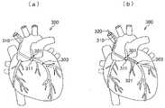
- FIGS. 1(a) and 1(b)are schematic diagrams showing an example of percutaneous coronary angioplasty treatment.
- (a)shows a state in which a guiding catheter is placed
- (b)shows a state in which a guide extension catheter is further placed.
- PCI treatmentpercutaneous coronary angioplasty treatment
- a distal end portion 311 of a guiding catheter 310is placed at the coronary artery ostium 301 .
- FIG.Insert the extension catheter 320 .
- the distal end portion 321 of the guide extension catheter 320is projected beyond the distal end of the guiding catheter 310 (toward the lesion 303).
- a distal end portion of a treatment catheter (not shown) passed through the guide extension catheter 320receives additional back support from the guide extension catheter 320 and is delivered toward the lesion 303 .
- the guiding cathetercan be pressed against the wall of the aorta on the opposite side of the ostium of the coronary artery even in cases where it is difficult for a treatment catheter or the like to pass through the affected area.
- the back support necessary for delivering a treatment device or the like to the affected areais strengthened against the resistance caused by bending or calcification of the coronary artery.
- the guide extension cathetercan also be applied to the treatment of the lower extremity region.
- FIG. 2shows a guide extension catheter according to an embodiment of the present invention, where (a) is a plan view and (b) is a side view.
- the guide extension catheter 1includes a guide portion 100 on the distal end side in the longitudinal direction and a push rod 200 (push member) on the proximal end side in the longitudinal direction.
- a distal end portion 200 a of the push rod 200is joined to a joint portion 150 positioned at the proximal end portion of the guide portion 100 .
- the guide part 100 and the push rod 200have flexibility to curve following the curved shape of the blood vessel.
- Ax in the drawingis the axis of the guide portion 100 .
- the guide portion 100takes an initial posture in which the axis Ax extends linearly and a curved posture in which the axis Ax curves.
- FIG. 3is a longitudinal sectional view schematically showing the detailed configuration of the guide portion according to one embodiment of the present invention.
- FIGS. 4A to 4Dare transverse cross-sectional views of respective portions in the longitudinal direction of the guide portion.
- FIG. 3shows a cross section of the guide section taken along the line AA in FIG. 2(a).
- FIGS. 4(a) to 4(d)show cross sections of the guide section taken along lines BB to EE in FIG. 3, respectively.
- the guide part 100has a hollow cylindrical guide part (cylindrical part) 110 having a lumen 111 penetrating in the longitudinal direction on the distal end side in the longitudinal direction, and has a concave guide surface continuous with the inner surface 111a of the lumen 111.
- a semi-cylindrical semi-cylindrical guide portion 155 having 157is provided on the proximal longitudinal side. Lumen 111 and concave guide surface 157 guide a procedural catheter device.
- the reinforcing portion 117 arranged in the longitudinally intermediate portion of the cylindrical guide portion 110includes an inner layer 131 that defines the inner surface 111a of the lumen 111 of the cylindrical guide portion 110, and an outer peripheral surface of the inner layer 131.
- An intermediate layer 140is arranged, and an outer layer 133 is arranged on the outer peripheral surface of the intermediate layer 140 .
- the intermediate layer 140is, for example, a cylindrical coil body 141A in which a wire 143 is spirally wound as shown in FIG. and a resin 147 that enters a space 145 between wires 143 and 143 that constitute the reinforcing body 141 .
- This embodimentis characterized in that the resin 147 is made of a material softer than the resin forming the outer layer 133 .
- cylindrical guide portion 110is generally cylindrical with a lumen 111 extending longitudinally therethrough.
- the cylindrical guide portion 110includes, in order from the distal end in the longitudinal direction toward the proximal end, a distal tip 113, a distal marker 115, a reinforcing portion 117 having a reinforcing body 141 embedded in its thickness, and a proximal marker. 119 and.
- the cylindrical guide portion 110includes an inner layer 131 that defines the inner surface 111a (the surface facing the lumen 111) of the cylindrical guide portion 110 over its entire longitudinal direction.
- the inner diameter d1, the outer diameter, and the thickness t1 of the inner layer 131are all substantially constant over the entire longitudinal direction.
- the cylindrical guide portion 110includes an outer layer 133 arranged radially outward of the inner layer 131 .
- the distal tip 113comprises an inner layer 131 and an outer layer 133 in intimate contact with the inner layer 131 .
- Distal marker 115 and proximal marker 119are radiopaque markers.
- Distal marker 115 and proximal marker 119are positioned between inner layer 131 and outer layer 133 .
- Distal marker 115 and proximal marker 119are ring-shaped.
- the distal side marker 115 and the proximal side marker 119are attached to the outer circumference of the tube forming the inner layer 131 by caulking.
- the reinforcing portion 117includes an inner layer 131 that defines the inner surface 111a of the cylindrical guide portion 110, an intermediate layer 140 arranged on the outer diameter side (peripheral surface) of the inner layer 131, and an outer diameter side (peripheral surface) of the intermediate layer 140. and an outer layer 133 disposed on the .
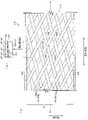
- FIG. 5A and 5Bare diagrams for explaining the configuration of an intermediate layer when the reinforcing body is a coil body
- FIG.is a cross-sectional view taken along line FF of (a).
- the left side of FIG. 5(a)shows the outer layer 133 of the reinforcing portion 117 in the GG cross section of FIG. 5(b), and corresponds to a view of the intermediate layer 140 observed from the H direction (from the outer diameter side).
- the right side of FIG. 5(a)shows each layer of the reinforcing portion 117 in the GG cross section of FIG. 5(b), and corresponds to a view of the intermediate layer 140 observed from the J direction (from the inner diameter side).
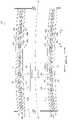
- FIGS. 6(a) and 6(b)are diagrams for explaining the configuration of the intermediate layer when the reinforcing body is a braided body, and are schematic plan views showing a part of the reinforcing portion in longitudinal section.
- the outer layer and the intermediate layerare drawn by the same method as the left side of FIG. 5(a)
- each layer and the intermediate layerare drawn by the same method as the right side of FIG. 5(a). It is
- the intermediate layer 140includes a flexible tubular reinforcing body 141 (141A, 141B) composed of one or more wires 143 and between the wires 143 constituting the reinforcing body 141 ( 5, between the portions 143a and 143b, and between the portions 143a to 143d in FIG. 6).
- the reinforcing body 141imparts kink resistance to the reinforcing portion 117 to prevent kink during bending. By providing the reinforcing body 141, the reinforcing portion 117 can freely bend in each direction without kinking.
- the reinforcing body 141 shown in this exampleis formed so that the inner diameter and the outer diameter are constant in the longitudinal direction.
- a tube forming the inner layer 131is inserted through the hollow interior of the reinforcing body 141 .
- a resin 147 that is softer (lower in hardness) than the resin forming the outer layer 133is used for the intermediate layer 140 .
- the resin 147is in the space 145 between the wires in a plan view (within a plane defined by the longitudinal direction and the circumferential direction of the reinforcing portion 117). It should be fully filled.
- the reinforcing body 141can be composed of a cylindrical coil body 141A in which one wire rod 143 is spirally wound at a predetermined pitch.
- the reinforcing body 141is composed of a tubular coil body 141A in which a plurality of wire rods 143, 143, . can.
- the coil body 141Ahas a spiral inter-wire space 145 (helical space) formed between portions 143a and 143b of the wire 143 adjacent along its longitudinal direction (axial direction).
- the inter-wire space 145penetrates the coil body 141A in the radially inner and outer directions.
- the adjacent portions 143a and 143bmay belong to the same wire 143 or may belong to different wires 143, 143, respectively.
- the resin 147has entered the space 145 between the wires.
- the resin 147may be arranged only in the spaces 145 between the wires, or may be arranged inside and outside the spaces 145 between the wires. In the former case, the resin 147 has a spiral shape within the intermediate layer 140, and in the latter case, the resin 147 has a cylindrical shape within the intermediate layer 140, for example.
- the resin 147contacts both the portion 143a and the portion 143b of the adjacent wire 143 over the entire length of the coil body 141A.
- the reinforcing body 141can be composed of a tubular braided body 141B in which a plurality of wire rods 143, 143, . . .
- the braided body 141Bincludes a wire rod helically woven with a predetermined pitch in the clockwise direction and a wire rod helically woven with a predetermined pitch in the counterclockwise direction. That is, the wires 143, 143, .
- the braided body 141Bhas mesh-shaped inter-wire spaces 145 formed between portions 143a to 143d of the wires 143, 143, .
- the inter-wire space 145has a substantially rhombic shape in plan view. Inter-wire spaces 145 are formed between different wires 143 , 143 . Adjacent portions (parts 143a and 143b, or portions 143c and 143d) in the wire rods inclined in the same direction may belong to the same wire rod 143 or to different wire rods 143, 143. may In this example, the inter-wire space 145 penetrates the braided body 141B in the radially inner and outer directions. The resin 147 has entered the space 145 between the wires. In the intermediate layer 140 , the resin 147 may be arranged only in the spaces 145 between the wires, or may be arranged inside and outside the spaces 145 between the wires.
- the approximately diamond-shaped resin 147is arranged in an oblique grid pattern in the intermediate layer 140 , and in the latter case, the resin 147 has a cylindrical shape in the intermediate layer 140 as an example. At least when the reinforcing portion 117 assumes the initial posture, the resin 147 contacts the portions 143a to 143d of the adjacent wire 143 over the entire length of the braided body 141B.
- Wire rods 143 forming reinforcing bodies 141may have various shapes such as a round wire with a circular cross-sectional shape and a square wire with a rectangular cross-sectional shape.
- a rectangular wire having a substantially rectangular cross-sectional shape(a flattened rectangular shape) as the wire rod 143.
- the rectangular wireis arranged so that its thickness direction (the direction of the short side of the cross section) coincides with the inner and outer radial directions of the reinforcing body 141 .
- the wire shown as a single wire 143 in FIGS. 5 and 6may be an aggregate of a plurality of wires, or a wire bundle in which a plurality of wires are bundled. That is, the coil body 141A may have a configuration in which a wire assembly or a wire bundle is spirally wound at a predetermined pitch. Further, the braided body 141B may have a structure in which a plurality of groups of wire rods or wire rod bundles are braided so as to intersect each other.
- FIG. 7corresponds to an enlarged view of a part of the reinforcing portion 117 shown in FIG.
- the horizontal directionis the longitudinal direction
- the vertical directionis the inner/outer diameter direction
- the lower partis the inner diameter side
- the upper partis the outer diameter side.
- FIG. 7shows a longitudinal sectional view when the reinforcing portion 117 assumes the initial posture shown in FIGS.
- FIG. 7shows an example in which the reinforcing body 141 is a coil body 141A, but the same is true when the reinforcing body 141 is a braided body 141B.
- FIG. 7shows an example using a rectangular wire as the wire, the same applies to the case of using a wire other than the rectangular wire.
- side surfaces 144a and 144bare surfaces extending along the radially inner and outer directions (vertical direction in the drawing) of the reinforcing portion 117 .
- Thicknesses t2 and t3are the lengths of the wire rod 143 and the resin 147 in directions along the inner and outer radial directions of the reinforcing portion 117, respectively.
- the resin 147 that constitutes the intermediate layer 140is in contact with both wire rods (portions 143a and 143b of the wire rod 143) adjacent to each other via the space 145 between the wire rods, at least when the intermediate layer 140 assumes the initial posture. .
- FIG. 7Ashows an example in which the thickness t3 of the resin 147 is thinner than the thickness t2 of the reinforcing member 141 (thickness t2>thickness t3). Resin 147 is in contact with portions 143a and 143b of wire rod 143 at portions of side surfaces 144a and 144b (portions within a range corresponding to thickness t3).
- FIG. 7Ashows an example in which the thickness t3 of the resin 147 is thinner than the thickness t2 of the reinforcing member 141 (thickness t2>thickness t3). Resin 147 is in contact with portions 143a and 143b of
- FIG. 7Cshows an example in which the thickness t3 of the resin 147 is greater than the thickness t2 of the wire rod 143 (thickness t2 ⁇ thickness t3).
- the resin 147is in contact with the portions 143a, 143b of the wire rod 143 on the entire sides 144a, 144b. Furthermore, the resin 147 enters between the wire 143 (143a, 143b) and the outer layer 133. As shown in FIG. Therefore, wire 143 is not in contact with outer layer 133 .
- FIG. 7Dshows another example in which the thickness t3 of the resin 147 is thicker than the thickness t2 of the wire rod 143 (thickness t2 ⁇ thickness t3).
- the resin 147is in contact with the portions 143a, 143b of the wire rod 143 on the entire sides 144a, 144b. Furthermore, the resin 147 enters between the wire 143 and the inner layer 131 and between the wire 143 and the outer layer 133 . Therefore, the wire 143 is not in contact with both the inner layer 131 and the outer layer 133 .
- the wire 143may contact both the inner layer 131 and the outer layer 133. As shown in FIG. 7(c), the wire 143 may contact either the inner layer 131 or the outer layer 133 (the figure shows an example in which only the inner layer 131 is contacted). As shown in FIG. 7(d), the wire rod 143 does not have to contact both the inner layer 131 and the outer layer 133.
- FIG. 7(c)the wire 143 may contact either the inner layer 131 or the outer layer 133 (the figure shows an example in which only the inner layer 131 is contacted).
- the wire rod 143does not have to contact both the inner layer 131 and the outer layer 133.
- FIG. 8is a vertical cross-sectional view showing the internal state of the curved reinforcing portion.
- the inter-wire space 145shrinks or extends in the longitudinal direction of the reinforcing portion 117 according to the curved shape of the reinforcing portion 117 .
- the resin 147deforms according to the deformation of the inter-wire space 145 .
- the resin 147apositioned on the side (lower side in the figure) where the radius of curvature is smaller than the center axis Ax of the reinforcing portion 117 is moved in the direction of the arrow K in the figure by the portions 143a and 143b of the wire rod 143. Compressed.
- the resin 147amaintains contact with both the portions 143a and 143b (side surfaces 144a and 144b) of the wire rod 143 .
- the resin 147b positioned on the side (upper side in the figure) where the radius of curvature is larger than the center axis Ax of the reinforcing part 117 when the reinforcing part 117 is curvedis elongated in the direction of the arrow L in the figure by the portions 143e and 143f of the wire rod 143. be done. At this time, it is desirable that the resin 147b maintain contact with both the portions 143e and 143f (side surfaces 144e and 144f) of the wire 143 .
- the resin 147bmay be separated from one or both of the portions 143e and 143f of the wire rod 143.
- FIG.When the reinforcing portion 117 is bent and deformed, the wire rod 143 is displaced according to the bent shape. Since the resin 147 forming the intermediate layer 140 is softer (lower in hardness) than the resin forming the outer layer 133 , the wire 143 smoothly displaces while deforming the resin 147 . Therefore, even if the outer layer 133 is made of a resin having a strength and/or hardness that can prevent the guide section 100 from being damaged, the blood vessel followability of the reinforcement section 117 is improved.
- the outer layer 133may contact side surfaces 144a and 144b of the wire rod 143.
- FIG. The length of contact of the outer layer 133 and the resin 147 with the side surfaces 144a and 144b of the wire rod 143determines the mobility of the wire rod 143 in the intermediate layer 140 (easiness of displacement). ) is more dominantly controlled by the resin 147 forming the intermediate layer 140 than by the resin forming the outer layer 133 .
- the hardness of the resin composing the outer layer 133 and the hardness of the resin 147 composing the intermediate layer 140 , or the difference in hardness between the two resinsindicates that the mobility of the wire rod 143 in the intermediate layer 140 is greater than that of the resin composing the outer layer 133 . is also set to be predominantly controlled by the resin 147 forming the intermediate layer 140 .
- the reinforcing portion 117may be configured such that flexibility increases stepwise or steplessly from the base end side to the tip end side.
- the reinforcing portion 117 shown in FIGS. 2 and 3includes a distal reinforcing portion 117A (first reinforcing portion) disposed on the distal end side in the longitudinal direction, and a distal reinforcing portion 117A adjacent to the distal reinforcing portion 117A and further extending than the distal reinforcing portion 117A. and a proximal side reinforcing portion 117B (second reinforcing portion) arranged on the proximal side in the longitudinal direction.
- the distal reinforcing portion 117Ahas higher flexibility than the proximal reinforcing portion 117B. That is, the distal reinforcing portion 117A is configured to follow the curved shape of the blood vessel more easily than the proximal reinforcing portion 117B.
- the reinforcement part 117may have three or more parts with different flexibility.
- the resin 147 forming the intermediate layer 140 of the distal reinforcing portion 117Acan be made of a resin that is softer than the resin 147 forming the intermediate layer 140 of the proximal reinforcing portion 117B. That is, the hardness of the resin 147 of the intermediate layer 140 can be set so as to gradually soften from the base end side of the reinforcing portion 117 toward the tip end side.
- the interval between the wires 143, 143 (the pitch of the coiled body, the opening of the braided body) of the distal side reinforcing portion 117Acan be set wider than that of the proximal side reinforcing portion 117B.
- the cross-sectional area of the wire rods 143, 143 of the distal side reinforcing portion 117Amay be smaller than that of the proximal side reinforcing portion 117B.
- the cross-sectional area of the wire 143here means the cross-sectional area in the direction perpendicular to the longitudinal direction of the wire 143 .
- the joint portion 150includes, in order from the distal end side in the longitudinal direction, a tubular joint portion 151 that constitutes the proximal end portion of the tubular guide portion 110, a lumen 111, and an external space. It has an inlet portion 153 open for communication and a semi-cylindrical guide portion 155 . As shown in FIG. 3 , the end face 153a of the entrance portion 153 is inclined with respect to the axis Ax of the cylindrical guide portion 110. As shown in FIG.
- the inclination angle of the end surface 153a with respect to the axis Axis appropriately set in consideration of the insertability of the catheter device into the lumen 111.
- a longitudinal base end surface 155a of the semi-cylindrical guide portion 155is inclined with respect to the axis Ax so that the base end side thereof is tapered.
- the inclination angle of the base end surface 155a with respect to the axis Axis appropriately set in consideration of the introducibility of the catheter device into the semi-cylindrical guide portion 155 and kink resistance (hardness change in the longitudinal direction).
- the inlet portion 153 and the semi-cylindrical guide portion 155are formed by forming the entire longitudinal direction of the guide portion 100 as a tubular body having a multi-layered structure, and then forming a portion of the tubular body in the circumferential direction (in the figure, It is produced by cutting and removing a cut region 161) indicated by a dotted line.
- the outer layer 133 of the joint portion 150may be made of resin that is harder than the outer layer 133 of the other tubular guide portion 110 .
- the outer layer 133 (133A to 133C) of the guide portion 100may be configured to become harder from the distal side toward the proximal side.
- the change in hardness of the guide portion 100 in the longitudinal directioncan be moderated.
- the blood vessel followability of the distal end side of the guide portion 100can be enhanced, and the change in hardness with the push rod 200 joined to the joint portion 150 can be moderated.
- the push rod 200is a linear member having a strength that allows the guide portion 100 to be pushed, pulled out, or rotated, and flexible enough to follow the shape of the blood vessel.
- the flexibility of the push rod 200is lower than that of the guide part 100 .
- the distal end portion 200a of the push rod 200is joined to the outer peripheral portion of the joint portion 150 using an adhesive or the like.
- the tip portion 200ais joined to the cylindrical body having the multilayer structure before the cut region 161 is cut and removed by using a heat-shrinkable tube that functions as an adhesive. For this reason, an adhesive layer 159 is formed around the outer periphery of the joint portion 150 using the heat-shrinkable tube. Note that the adhesive layer 159 shown in FIG.
- a tab 210is attached to the proximal end of the push rod 200 to serve as a grip when the guide extension catheter 1 is operated.
- Each member constituting the guide extension catheter 1is integrated using adhesive, welding, welding, thermal bonding, brazing, bonding, mechanical bonding, or other suitable method.
- the guide extension catheter 1can be produced, for example, by the following procedure.
- the mandrelis inserted into the hollow portion of the tube forming the inner layer 131 .
- a reinforcing body 141is arranged around the outer circumference of the tube. That is, the tube with the mandrel inserted is inserted into the hollow portion of the reinforcing body 141 .
- a distal marker 115 and a proximal marker 119are positioned on the outer circumference of the tube adjacent to the longitudinal ends of the stiffener 141, and the markers are crimped to integrate with the tube. Let this be the first tube assembly.
- a tube made of the resin 147 forming the intermediate layer 140 and a tube forming the outer layer 133are prepared.
- a tube of resin 147is inserted into the tube for outer layer 133 . This is called the second tube assembly.
- a plurality of tubes of the resin 147 having different hardnessare prepared.
- Each tube of resin 147is placed at a predetermined longitudinal position within the tube for outer layer 133 to form a second tube assembly.
- the first tube assemblyis inserted into the hollow portion of the second tube assembly so that the longitudinal positions of the resin 147 and the reinforcing body 141 are matched.
- the entire outer peripheral portion of the second tube assemblyis compressed in the inner diameter direction to bring the two tube assemblies into close contact and integrate them. Thereby, a cylindrical body having a multilayer structure is obtained.
- the proximal end of the tubular bodyis covered with a heat-shrinkable tube forming an adhesive layer 159 .
- the distal end portion 200a of the push rod 200is inserted between the heat-shrinkable tube and the cylindrical body.
- the heat-shrinkable tubeis shrunk to join the tubular body and the push rod 200 .
- the cut area 161 shown in FIG. 3is cut and removed.
- the guide extension catheter 1is manufactured, for example, as follows. That is, as a tube forming the inner layer 131, a tube having a longitudinal length capable of forming the guide portion 100 is prepared. Using the tube, a first tube assembly is produced in the same manner as in the first production method. A tube of resin 147 is inserted into the tube for outer layer 133A to fabricate a second tube assembly in the same manner as in the first fabrication method.
- the first and second tube assembliesare brought into close contact and integrated in the same manner as in the first manufacturing method so that the base ends of the tubes forming the inner layer 131 are exposed to the outside.
- the base ends of the tubes forming the inner layer 131are covered with a tube for the outer layer 133B and a tube for the outer layer 133C.
- itis made into a tubular body having a multilayer structure.
- the longitudinal base end portion of the outer layer 133A and the entire longitudinal direction of the outer layers 133B and 133Care covered with a heat-shrinkable tube forming an adhesive layer 159 .
- a distal end portion 200a of a push rod 200is inserted between the heat-shrinkable tube and the cylindrical body.
- the heat-shrinkable tubeis shrunk to join the tubular body and the push rod 200 .
- the outer layers 133A-133Care longitudinally integrated with a heat-shrinkable tube. Finally, the cut area 161 shown in FIG. 3 is cut and removed.
- Examples of dimensions of each part, examples of materials used for each partare set as follows.
- the total length of the guide extension catheter 1is 1000 mm to 2000 mm.
- the longitudinal length of the tubular guide portion 110is 100 mm to 500 mm
- the longitudinal length of the semi-cylindrical guide portion 155is 10 to 200 mm
- the longitudinal length of the push rod 200is 1000 mm to 1300 mm.
- the inner diameter of the cylindrical guide portion 110is 1.1 mm to 1.8 mm (Fr to Fr)
- a biocompatible material having lubricityis used for the inner layer 131 of the guide part 100 .
- PTFEpolytetrafluoroethylene
- PFAperfluoroalkoxyalkane
- HDPAhigh density polyethylene
- a material having manipulative compatibilityis used for the wires constituting the reinforcing body 141 (the coil body 141A and the braided body 141B).
- stainless steelSUS304WPB
- other types of stainless steel, cobalt alloys, nickel-titanium alloys, tungsten, and the likecan be used as metal materials for the wires constituting the reinforcing body 141 .
- As the resin materialpolyamide, liquid crystal polymer (LCP), polyetheretherketone (PEEK), polyphenylene sulfide (PPS), perfluoroalkoxyalkane (PFA), etc. can be used.
- a biocompatible elastomeris used for the resin 147 forming the intermediate layer 140 of the reinforcing portion 117 .
- a polyurethane-based thermoplastic elastomeris used.
- polyether block amide, polyester elastomer, or the likecan be used for the resin 147 .
- the hardness of the resin 147is 10 or more and less than 60 (Shore D hardness). By setting the Shore D hardness of the resin 147 in this manner, the mobility of the wire 143 within the intermediate layer 140 can be ensured.
- the hardness of the resin 147 forming the intermediate layer 140 of the tip side reinforcing portion 117Ais set to 10 or more and less than 40 (Shore D hardness).
- the hardness of the resin 147 forming the intermediate layer 140 of the proximal side reinforcing portion 117Bis set to 40 or more and less than 60 (Shore D hardness).
- the difference in hardness between the resins 147, 147 of the distal reinforcing portion 117A and the proximal reinforcing portion 117Bis preferably 20 (Shore D hardness) or more.
- a biocompatible resin (elastomer)is used for the outer layer 133 .
- a polyether block amide copolymer(PEBAX (registered trademark)
- PEBAXpolyether block amide copolymer
- polyamide, polyamide elastomer, polyester, and polyethylenecan be used for the outer layer 133 .
- the hardness of the resin forming the outer layer 133is 60 or more and less than 75 (Shore D hardness). By setting the hardness of the resin forming the outer layer 133 in this manner, it is possible to ensure strength enough to prevent the guide portion 100 from being damaged.
- the difference in hardness between the resin forming the outer layer 133 and the resin 147 forming the intermediate layer 140 of the tip side reinforcing portion 117Ais 20 or more and less than 65 (Shore D hardness).
- An X-ray opaque materialis used for the distal marker 115 and the proximal marker 119 .
- platinum iridium90Pt-10Ir
- the distal marker 115 and the proximal marker 119can be made of gold, platinum, palladium, tantalum, tungsten alloys, polymer materials containing X-ray opaque fillers (barium sulfate, bismuth subcarbonate, etc.).
- a biocompatible materialis used for the push rod 200 .
- a cobalt alloyis used.
- stainless steel, nickel-titanium alloys, cobalt, chromium, molybdenum, and nickel-based alloyscan be used as metal materials for the push rod 200 .
- the resin 147 forming the intermediate layer 140is softer (lower in hardness) than the resin forming the outer layer 133 . Therefore, the resin 147 does not hinder the smooth displacement of the wire 143 forming the reinforcing body 141 . If the intermediate layer 140 were not provided with the resin 147 , the displacement of the wire 143 would be restricted by the hard outer layer 133 . Even if a resin having a hardness equivalent to that of the outer layer 133 enters the space 147 between the wires, the displacement of the wires 143 is limited by the hard resin. As described above, according to the present embodiment, the blood vessel followability of the reinforcing portion 117 is improved.
- This embodimentis a guide extension catheter 1 having a tubular portion (tubular guide portion 110) having a lumen 111 penetrating in the longitudinal direction on the distal end side in the longitudinal direction, and the tubular portion is the intermediate portion in the longitudinal direction.
- the reinforcing portion 117has an inner layer 131 that defines the inner surface 111a of the lumen of the cylindrical portion, an intermediate layer 140 arranged on the outer peripheral surface of the inner layer, and an outer layer 133 arranged on the outer peripheral surface of the intermediate layer.
- the intermediate layeris a cylindrical coil body 141A in which a wire 143 is spirally wound, or a cylindrical braided body 141B in which a plurality of wires are intersected. It is characterized in that it includes a resin 147 which is softer than the resin forming the outer layer and which enters into the inter-wire space 145 formed between the wires forming the reinforcing body.
- the blood vessel followability of the cylindrical guide portion arranged on the distal side of the guide extension catheteris improved.
- the intermediate layeris configured to include the reinforcing body and the resin that enters the space between the wire rods of the reinforcing body.
- the resin forming the intermediate layeris softer (lower in hardness) than the resin forming the outer layer. Therefore, when the cylindrical portion is bent and deformed, the wire material constituting the reinforcing body can be smoothly displaced within the intermediate layer. Even if a resin having a strength or hardness capable of preventing damage is used for the outer layer, the blood vessel followability of the tubular portion is improved.
- the guide extension catheter 1is characterized in that the resin 147 forming the intermediate layer 140 is in contact with both adjacent wire rods 143 (portions 143a to 143f) via the space 145 between the wire rods. At least when the reinforcing portion 117 assumes the initial posture, the resin forming the intermediate layer fills the entire inter-wire space in plan view (within the plane defined by the longitudinal direction and the circumferential direction of the reinforcing portion). It is desirable to be The resin forming the intermediate layer may be thicker than the wire, may be as thick as the wire, or may be thinner than the wire.
- the resin located on the side where the radius of curvature becomes smaller than the axis Ax when the cylindrical portion is curvedis compressed by both adjacent wire rods. Since the resin forming the intermediate layer is softer (lower in hardness) than the resin forming the outer layer, it does not interfere with the movement of the reinforcing member.
- the guide extension catheter 1 according to this aspectis characterized in that the Shore D hardness of the resin forming the outer layer 133 is 60 or more and less than 75. By setting the Shore D hardness of the resin forming the outer layer in this way, it is possible to secure strength that can prevent the guide portion 100 from being damaged.
- the reinforcing section 117includes a distal reinforcing section 117A arranged on the distal side in the longitudinal direction, and a proximal reinforcing section adjacent to the distal reinforcing section and extending in the longitudinal direction from the distal reinforcing section.
- the resin 147 forming the intermediate layer 140 of the distal-side reinforcing portionis softer than the resin 147 forming the intermediate layer of the proximal-side reinforcing portion. and The flexibility of the reinforcing portion can be controlled according to the hardness of the resin.
- the flexibility of the reinforcing portionwill be high, and if a relatively hard resin is used for the intermediate layer, the flexibility of the reinforcing portion will be low.
- the hardness of the resin along the longitudinal directionit is possible to obtain a reinforcing portion having different flexibility depending on the position in the longitudinal direction.
- the flexibility of the distal end side of the reinforcing portionis relatively high, and the flexibility of the proximal end side of the reinforcing portion is relatively low. Therefore, the change in hardness with the push rod 200 arranged at the proximal end of the guide extension catheter can be moderated. According to this aspect, it is possible to prevent kink and breakage of the guide extension catheter due to sudden change in hardness in the longitudinal direction.
- the hardness difference between the Shore D hardness of the resin forming the outer layer 133 and the Shore D hardness of the resin 147 forming the intermediate layer 140 of the tip reinforcing portion 117Ais 20 or more. Characterized by By setting the hardness difference in this manner, the mobility of the wire rod 143 in the intermediate layer is controlled predominantly by the resin forming the intermediate layer rather than by the resin forming the outer layer.
- the guide extension catheter 1is characterized in that the Shore D hardness of the resin 147 forming the intermediate layer 140 of the tip reinforcing portion 117A is 10 or more and less than 40.
- the Shore D hardness of the resin forming the intermediate layeris 10 or more and less than 40.
Landscapes
- Health & Medical Sciences (AREA)
- Life Sciences & Earth Sciences (AREA)
- Biophysics (AREA)
- Pulmonology (AREA)
- Engineering & Computer Science (AREA)
- Anesthesiology (AREA)
- Biomedical Technology (AREA)
- Heart & Thoracic Surgery (AREA)
- Hematology (AREA)
- Animal Behavior & Ethology (AREA)
- General Health & Medical Sciences (AREA)
- Public Health (AREA)
- Veterinary Medicine (AREA)
- Media Introduction/Drainage Providing Device (AREA)
Abstract
Description
Translated fromJapanese本発明はガイドエクステンションカテーテルに関する。The present invention relates to guide extension catheters.
心臓や血管等の病気に対して、カテーテルを血管に挿入して治療する低侵襲性のインターベンション治療が広く実施されている。インターベンション治療においては、処置用のカテーテルデバイス(例:バルーンカテーテル、ステントデリバリーカテーテル等)を病変部に到達させるために、ガイディングカテーテルが使用される。A minimally invasive interventional treatment that treats diseases such as the heart and blood vessels by inserting a catheter into the blood vessel is widely practiced. In interventional therapy, guiding catheters are used to guide catheter devices for treatment (eg, balloon catheters, stent delivery catheters, etc.) to lesions.
ガイディングカテーテルは血管壁面に押し付けられることにより生まれる反力を利用して、カテーテルデバイスの送達をサポートする。しかし、ガイディングカテーテルのみではバックサポートが不足し、例えば狭窄部を越えてカテーテルデバイスを病変部に到達させることができない場合がある。The guiding catheter supports the delivery of the catheter device by using the reaction force generated by being pressed against the wall of the blood vessel. However, the guiding catheter alone does not provide sufficient back support, and in some cases, the catheter device cannot cross the stenosis and reach the lesion.
そこで、追加のバックサポートを得るために、ガイディングカテーテルに加えてガイドエクステンションカテーテルが使用される。Therefore, a guide extension catheter is used in addition to the guiding catheter to obtain additional back support.
特許文献1に記載されているように、ガイドエクステンションカテーテルは、ガイディングカテーテル内に挿入され、ガイディングカテーテルの先端を越えて遠位側に突出する。ガイドエクステンションカテーテルは、ガイドカテーテルに対して追加のバックサポートを提供する。追加のバックサポートにより、カテーテルデバイスは狭窄部を越えて病変部に送達される。As described in
特許文献1においては、ガイドエクステンションカテーテルの遠位側(先端側)に配置された筒状の遠位シャフトの入口ポートを螺旋形状とすることにより、カテーテルデバイス(インターベンショナル冠状動脈デバイス)を遠位シャフト内に容易に進入させるように構成している。In
しかし、特許文献1においては、遠位シャフトの血管追従性の改善については考慮されていない。However, in
本発明は、上述の事情に鑑みてなされたものであり、ガイドエクステンションカテーテルの先端側に配置された筒状部の血管追従性を改善することを目的とする。The present invention has been made in view of the circumstances described above, and aims to improve the blood vessel followability of a tubular portion disposed on the distal end side of a guide extension catheter.
上記の課題を解決するために、本発明は、長手方向に貫通した内腔を有する筒状部を長手方向の先端側に備えたガイドエクステンションカテーテルであって、前記筒状部は長手方向の中間部に、該筒状部の前記内腔の内面を規定する内層と、該内層の外周面に配置された中間層と、該中間層の外周面に配置された外層と、を有した補強部を備え、前記中間層は、線材が螺旋状に巻回された筒状のコイル体、又は、複数の線材が交差するように編組された筒状の編組体からなる補強体と、該補強体を構成する前記線材間に形成された線材間空間に入り込むと共に、前記外層を構成する樹脂よりも柔らかい樹脂と、を含み構成されていることを特徴とする。In order to solve the above problems, the present invention provides a guide extension catheter having a tubular portion having a longitudinally penetrating lumen at its distal end in the longitudinal direction, wherein the tubular portion is located in the middle of the longitudinal direction. A reinforcing portion having an inner layer that defines the inner surface of the lumen of the tubular portion, an intermediate layer that is disposed on the outer peripheral surface of the inner layer, and an outer layer that is disposed on the outer peripheral surface of the intermediate layer. The intermediate layer comprises a cylindrical coil body in which a wire is spirally wound, or a cylindrical braided body in which a plurality of wires are intersected and braided, and the reinforcing body and a resin that is softer than the resin that constitutes the outer layer.
本発明によれば、ガイドエクステンションカテーテルの先端側に配置された筒状部の血管追従性が向上する。According to the present invention, the vessel followability of the cylindrical portion arranged on the distal end side of the guide extension catheter is improved.
以下、本発明を図に示した実施形態を用いて詳細に説明する。但し、この実施形態に記載される構成要素、種類、組み合わせ、形状、その相対配置などは特定的な記載がない限り、この発明の範囲をそれのみに限定する主旨ではなく単なる説明例に過ぎない。The present invention will be described in detail below using embodiments shown in the drawings. However, unless there is a specific description, the components, types, combinations, shapes, relative arrangements, and the like described in this embodiment are merely illustrative examples and not intended to limit the scope of the present invention. .
〔ガイドエクステンションカテーテルの使用例〕
心臓や血管等の病気に対して、カテーテルを血管に挿入して治療する低侵襲性のインターベンション治療が広く実施されている。インターベンション治療においては、処置用のカテーテル等(例:バルーンカテーテル、ステントデリバリーカテーテル、ガイドワイヤ等)を病変部に到達させるために、ガイディングカテーテルが使用される。[Example of using a guide extension catheter]
2. Description of the Related Art Minimally invasive interventional therapy, in which a catheter is inserted into a blood vessel to treat diseases of the heart, blood vessels, etc., is widely practiced. In interventional therapy, a guiding catheter is used to allow treatment catheters (eg, balloon catheters, stent delivery catheters, guidewires, etc.) to reach lesions.
ガイディングカテーテルは、処置用のカテーテルを挿通する内腔を備えた中空筒状であり、ガイディングカテーテルの先端部を病変部の直前位置に配置することによって、内腔を通過する処置用のカテーテルを病変部に送達する。The guiding catheter has a hollow tubular shape with a lumen through which the catheter for treatment is inserted. delivered to the lesion.
しかし、屈曲・蛇行病変、石灰化病変、抹消病変といった、いわゆる複雑病変を含む症例では、ガイディングカテーテルによるサポートのみでは、処置用のカテーテルを病変部へ送達させることが困難な場合がある。
このような場合には、ガイディングカテーテルに加えて、ガイドエクステンションカテーテルが使用される。However, in cases involving so-called complex lesions such as tortuous/tortuous lesions, calcified lesions, and peripheral lesions, it may be difficult to deliver the catheter for treatment to the lesion site only with the support of the guiding catheter.
In such cases, a guide extension catheter is used in addition to the guiding catheter.
図1(a)、(b)は、経皮的冠動脈形成術治療の例を示す模式図である。(a)はガイディングカテーテルを配置した状態を示し、(b)は更にガイドエクステンションカテーテルを配置した状態を示す。
図1(a)に示すように、心臓300の経皮的冠動脈形成術治療(PCI治療)では、ガイディングカテーテル310の先端部311を冠動脈入口部301に配置する。処置用のカテーテルを冠動脈入口部301から遠位にある病変部303に到達させるためのバックサポートを強化するために、図1(b)に示すように、ガイディングカテーテル310の内腔内にガイドエクステンションカテーテル320を挿入する。そして、ガイドエクステンションカテーテル320の先端部321を、ガイディングカテーテル310の先端を越えて遠位方向に(病変部303に向けて)突出させる。FIGS. 1(a) and 1(b) are schematic diagrams showing an example of percutaneous coronary angioplasty treatment. (a) shows a state in which a guiding catheter is placed, and (b) shows a state in which a guide extension catheter is further placed.
As shown in FIG. 1( a ), in percutaneous coronary angioplasty treatment (PCI treatment) of a
ガイドエクステンションカテーテル320内に挿通された処置用のカテーテル(不図示)の先端部分は、ガイドエクステンションカテーテル320から追加のバックサポートを受けて病変部303に向けて送達される。
ガイドエクステンションカテーテルを使用すれば、処置用のカテーテル等が病変部を通過困難な症例であっても、冠動脈入口部の対側にある大動脈壁面にガイディングカテーテルが押し付けられる。これにより、冠動脈の屈曲や石灰化などから生じる抵抗に対して処置用のデバイス等を病変部に送達させる際に必要なバックサポートは強化される。
なお、ガイドエクステンションカテーテルは下肢領域の治療にも適用可能である。A distal end portion of a treatment catheter (not shown) passed through the
If a guide extension catheter is used, the guiding catheter can be pressed against the wall of the aorta on the opposite side of the ostium of the coronary artery even in cases where it is difficult for a treatment catheter or the like to pass through the affected area. As a result, the back support necessary for delivering a treatment device or the like to the affected area is strengthened against the resistance caused by bending or calcification of the coronary artery.
In addition, the guide extension catheter can also be applied to the treatment of the lower extremity region.
〔第一の実施形態〕
図2は、本発明の一実施形態に係るガイドエクステンションカテーテルを示す図であり、(a)は平面図であり、(b)は側面図である。[First embodiment]
FIG. 2 shows a guide extension catheter according to an embodiment of the present invention, where (a) is a plan view and (b) is a side view.
ガイドエクステンションカテーテル1は、長手方向の先端側にガイド部100を備え、長手方向の基端側にプッシュロッド200(プッシュ部材)を備える。プッシュロッド200の先端部200aは、ガイド部100の基端部に位置する継手部150に接合されている。ガイド部100とプッシュロッド200は、血管の湾曲形状に追従して湾曲する可撓性を有する。
ここで、図中Axは、ガイド部100の軸線である。ガイド部100は、軸線Axが直線的に伸びた初期姿勢と、軸線Axが湾曲した湾曲姿勢とを取る。The
Here, Ax in the drawing is the axis of the
<ガイド部>
図3は、本発明の一実施形態に係るガイド部の詳細構成を模式的に示した縦断面図である。図4(a)~(d)は、ガイド部の長手方向の各部における横断面図である。
図3には、ガイド部を図2(a)のA-A線で切断した断面を示している。図4(a)~(d)は夫々、ガイド部を図3のB-B線~E-E線で切断した断面を示している。<Guide part>
FIG. 3 is a longitudinal sectional view schematically showing the detailed configuration of the guide portion according to one embodiment of the present invention. FIGS. 4A to 4D are transverse cross-sectional views of respective portions in the longitudinal direction of the guide portion.
FIG. 3 shows a cross section of the guide section taken along the line AA in FIG. 2(a). FIGS. 4(a) to 4(d) show cross sections of the guide section taken along lines BB to EE in FIG. 3, respectively.
ガイド部100は、長手方向に貫通した内腔111を有する中空筒状の筒状ガイド部(筒状部)110を長手方向の先端側に備え、内腔111の内面111aと連続する凹状ガイド面157を有した半筒状の半筒状ガイド部155を長手方向の基端側に備える。内腔111と凹状ガイド面157は、処置用のカテーテルデバイスを案内する。The
本実施形態において、筒状ガイド部110の長手方向の中間部に配置された補強部117は、筒状ガイド部110の内腔111の内面111aを規定する内層131と、内層131の外周面に配置された中間層140と、中間層140の外周面に配置された外層133と、を備える。
中間層140は、例えば図5に示すように線材143が螺旋状に巻回された筒状のコイル体141A、又は、図6に示すように複数の線材143,143…が交差するように編組された筒状の編組体141B等からなる補強体141と、補強体141を構成する線材143,143間に形成された線材間空間145に入り込む樹脂147とを含み構成される。
本実施形態においては、樹脂147を、外層133を構成する樹脂よりも柔らかい材料から構成した点に特徴がある。In the present embodiment, the reinforcing
The
This embodiment is characterized in that the
<<筒状ガイド部>>
図3及び図4に示すように、筒状ガイド部110は、長手方向に貫通した内腔111を有する概略円筒状である。<<cylindrical guide part>>
As shown in FIGS. 3 and 4, the
筒状ガイド部110は、長手方向の先端から基端に向かって順に、先端チップ113と、先端側マーカ115と、肉厚内に補強体141が埋設された補強部117と、基端側マーカ119と、を備える。基端側マーカ119よりも基端側に位置する筒状ガイド部110の部分は、ガイド部100とプッシュロッド200とを接続する継手部150を構成する。
筒状ガイド部110は、その長手方向の全体において、筒状ガイド部110の内面111a(内腔111に面した表面)を規定する内層131を備える。内層131の内径d1、外径、及び肉厚t1は、何れも長手方向の全体に亘って実質的に一定である。
筒状ガイド部110は、内層131よりも外径側に配置された外層133を備える。The
The
The
先端チップ113は、内層131と、内層131に密着した外層133とを備える。
先端側マーカ115と基端側マーカ119はX線不透マーカである。先端側マーカ115と基端側マーカ119は、内層131と外層133との間に配置されている。先端側マーカ115と基端側マーカ119は、リング状である。先端側マーカ115と基端側マーカ119は、内層131を構成するチューブの外周にかしめにより取り付けられている。The
<<補強部>>
補強部117は、筒状ガイド部110の内面111aを規定する内層131と、内層131の外径側(外周面)に配置された中間層140と、中間層140の外径側(外周面)に配置された外層133とを備える。<<Reinforcement part>>
The reinforcing
図5は、補強体をコイル体とした場合の中間層の構成を説明する図であり、(a)は補強部の一部を縦断面にて示した模式的平面図であり、(b)は(a)のF-F断面図である。図5(a)の左側は補強部117の外層133を図5(b)のG-G断面で示すと共に、中間層140をH方向から(外径側から)観察した図に相当する。図5(a)の右側は補強部117の各層を図5(b)のG-G断面で示すと共に、中間層140をJ方向から(内径側から)観察した図に相当する。5A and 5B are diagrams for explaining the configuration of an intermediate layer when the reinforcing body is a coil body, FIG. is a cross-sectional view taken along line FF of (a). The left side of FIG. 5(a) shows the
図6(a)、(b)は、補強体を編組体とした場合の中間層の構成を説明する図であり、補強部の一部を縦断面にて示した模式的平面図である。図6(a)では図5(a)の左側と同様の方法で外層と中間層が描画され、図6(b)では図5(a)の右側と同様の方法で各層と中間層が描画されている。FIGS. 6(a) and 6(b) are diagrams for explaining the configuration of the intermediate layer when the reinforcing body is a braided body, and are schematic plan views showing a part of the reinforcing portion in longitudinal section. In FIG. 6(a), the outer layer and the intermediate layer are drawn by the same method as the left side of FIG. 5(a), and in FIG. 6(b), each layer and the intermediate layer are drawn by the same method as the right side of FIG. 5(a). It is
図5(a)、及び図6中、中間層140に対して紙面と垂直な方向に重なる内層131と外層133は図示されていない。5(a) and 6, the
中間層140は、1本又は複数本の線材143から構成される可撓性を有した筒状の補強体141(141A,141B)と、補強体141を構成する線材143と線材143の間(図5では部分143a,143b間、図6では部分143a~143d間)に形成される線材間空間(隙間)145内に進入した弾性を有する樹脂147(エラストマー)と、を含み、構成される。
補強体141は補強部117に対して、湾曲時におけるキンクを防止する耐キンク性を付与する。補強部117は補強体141を備えることにより、キンクせずに各方向に自在に湾曲する。本例に示す補強体141は、内径と外径が長手方向に一定となるように形成される。補強体141の中空内部には、内層131を構成するチューブが挿通される。
中間層140には、外層133を構成する樹脂よりも柔らかい(硬度が低い)樹脂147が使用される。少なくとも補強部117が、その軸線Axが直線的に伸びた初期姿勢をとるとき、樹脂147は平面視(補強部117の長手方向と周方向とにより規定される平面内)において線材間空間145の全体に充填されていることが望ましい。The
The reinforcing
A
(補強体をコイル体とする例)
図5に示すように、補強体141は、1本の線材143が所定のピッチで螺旋状に巻回された筒状のコイル体141Aから構成できる。又は、補強体141は、所定の間隔を空けて並行に配置された複数本の線材143,143…が、同方向に所定のピッチで螺旋状に巻回された筒状のコイル体141Aから構成できる。
コイル体141Aは、その長手方向(軸方向)に沿って隣り合う線材143の部分143aと部分143bとの間に形成された螺旋状の線材間空間145(螺旋状空間)を有する。線材間空間145は、コイル体141Aの内外径方向に貫通している。なお、隣接する部分143aと部分143bは、夫々同一の線材143に属していてもよいし、異なる線材143,143に属していてもよい。
樹脂147は線材間空間145の内部に進入している。樹脂147は中間層140内において、線材間空間145内のみに配置されてもよいし、線材間空間145の内部及び外部に配置されてもよい。前者の場合、樹脂147は中間層140内で螺旋形状となり、後者の場合、樹脂147は一例として中間層140内で筒形状となる。
少なくとも補強部117が初期姿勢をとるとき、樹脂147は、コイル体141Aの長手方向の全域において、隣接する線材143の部分143aと部分143bの双方に接触する。(Example in which the reinforcing body is a coil body)
As shown in FIG. 5, the reinforcing
The
The
At least when the reinforcing
(補強体を編組体とする例)
図6に示すように、補強体141は、複数の線材143,143…が交差するように編組された筒状の編組体141Bから構成できる。編組体141Bは、右回り方向に所定のピッチで螺旋状に編み込まれた線材と、左回り方向に所定のピッチで螺旋状に編み込まれた線材とを含む。即ち、線材143,143…は、編組体141Bの長手方向或いは周方向に所定の間隔が空くように離間して配置されている。
編組体141Bは、平面視で隣り合った線材143,143…の各部分143a~143dの間に形成された網目状の線材間空間145を有する。線材間空間145は、平面視で概略ひし形状とされる。線材間空間145は、異なる線材143、143同士の間に形成される。なお、同方向に傾斜した線材中の隣接する部分同士(部分143aと部分143b同士、又は部分143cと143d同士)は同一の線材143に属していてもよいし、異なる線材143,143に属していてもよい。本例において、線材間空間145は、編組体141Bの内外径方向に貫通している。
樹脂147は線材間空間145の内部に進入している。樹脂147は中間層140内において、線材間空間145内のみに配置されてもよいし、線材間空間145の内部及び外部に配置されてもよい。前者の場合、概略ひし形状の樹脂147は中間層140内で斜め格子状に配置され、後者の場合、樹脂147は一例として中間層140内で筒形状となる。
少なくとも補強部117が初期姿勢をとるとき、樹脂147は、編組体141Bの長手方向の全域において、隣接する線材143の各部分143a~143dに接触する。(Example in which the reinforcing body is a braided body)
As shown in FIG. 6, the reinforcing
The braided body 141B has mesh-shaped
The
At least when the reinforcing
(補強体を構成する線材の形態)
補強体141(141A,141B)を構成する線材143には、横断面形状が円形状の丸線、横断面形状が矩形状の角線等、種々の形状を採用できる。
特に、本例においては耐キンク性の向上と補強体141の薄肉化の観点から、線材143として横断面形状が概略平角状(偏平した矩形状)の平角線を用いるのが好適である。この場合、平角線は、その厚さ方向(横断面の短辺の方向)が補強体141の内外径方向に一致するように配置される。
なお、図5及び図6において単一の線材143として図示された線材は、複数の線材の集合体、或いは、複数の線材が束ねられた線材束とされてもよい。即ち、コイル体141Aは、線材の集合体又は線材束が所定のピッチでらせん状に巻回された構成であってもよい。また、編組体141Bは、線材の集合体又は線材束が複数組、交差するように編組された構成であってもよい。(Form of wire constituting reinforcing body)
In particular, in this example, from the viewpoint of improving the kink resistance and reducing the thickness of the reinforcing
The wire shown as a
(線材と樹脂との関係)
図7(a)~(d)は、補強部の内部状態を示す縦断面図である。図7は、図2に示す補強部117の一部を拡大して示した図に相当する。図7中、左右方向が長手方向、上下方向が内外径方向、下方が内径側、上方が外径側である。また、図7は、補強部117が図5及び図6に示す初期姿勢をとるときの縦断面図を示す。図7は、補強体141をコイル体141Aとした場合の例を示しているが、補強体141を編組体141Bとした場合も同様である。図7には、線材として平角線を用いた例を示したが、線材として平角線以外を用いた場合も同様である。(Relationship between wire and resin)
7(a) to (d) are longitudinal cross-sectional views showing the internal state of the reinforcing portion. FIG. 7 corresponds to an enlarged view of a part of the reinforcing
以下では、隣接する線材143の部分143a,143bの表面のうち、互いに対向した面を側面144a,144bとする。側面144a,144bは、補強部117の内外径方向(図中上下方向)に沿って伸びる面である。また、肉厚t2、t3は、夫々、補強部117の内外径方向に沿った方向における線材143と樹脂147の長さである。
各図に示すように、中間層140を構成する樹脂147は、少なくとも初期姿勢を取るとき、線材間空間145を介して隣接する両線材(線材143の各部分143a,143b)に接触している。Hereinafter, of the surfaces of the
As shown in each figure, the
図7(a)は、樹脂147の肉厚t3が補強体141の肉厚t2よりも薄い場合(肉厚t2>肉厚t3)の例である。樹脂147は、側面144a,144bの一部分(肉厚t3に相当する範囲の部分)において、線材143の部分143a,143bと接触している。
図7(b)は、樹脂147の肉厚t3が線材143の肉厚t2と同等である場合(肉厚t2=肉厚t3)の例である。樹脂147は、側面144a,144bの全体において、線材143の部分143a,143bと接触している。
図7(c)は、樹脂147の肉厚t3が線材143の肉厚t2よりも厚い場合(肉厚t2<肉厚t3)の例である。樹脂147は、側面144a,144bの全体において、線材143の部分143a,143bと接触している。更に、樹脂147は、線材143(143a,143b)と外層133との間に入り込んでいる。このため、線材143は外層133とは接触していない。
図7(d)は、樹脂147の肉厚t3が線材143の肉厚t2よりも厚い場合(肉厚t2<肉厚t3)の他の例である。樹脂147は、側面144a,144bの全体において、線材143の部分143a,143bと接触している。更に、樹脂147は、線材143と内層131との間、及び、線材143と外層133との間に入り込んでいる。このため、線材143は内層131と外層133の双方には接触していない。FIG. 7A shows an example in which the thickness t3 of the
FIG. 7B shows an example in which the thickness t3 of the
FIG. 7C shows an example in which the thickness t3 of the
FIG. 7D shows another example in which the thickness t3 of the
図7(a)、(b)に示すように、線材143は内層131と外層133の双方に接触してもよい。図7(c)に示すように、線材143は内層131と外層133の一方に接触してもよい(図では内層131のみに接触した例を示している)。図7(d)に示すように、線材143は内層131と外層133の双方に接触しなくてもよい。As shown in FIGS. 7(a) and 7(b), the
図8は、湾曲させた補強部の内部状態を示す縦断面図である。
線材間空間145は補強部117の湾曲形状に応じて、補強部117の長手方向に縮小し、又は伸長する。樹脂147は、線材間空間145の変形に応じて変形する。
補強部117が湾曲したときに補強部117の中心軸線Axよりも曲率半径が小さくなる側(図中下側)に位置する樹脂147aは、線材143の部分143a,143bによって図中矢印K方向に圧縮される。このため、樹脂147aは、線材143の部分143a,143b(側面144a,144b)の双方に接触した状態を維持する。
補強部117が湾曲したときに補強部117の中心軸線Axよりも曲率半径が大きくなる側(図中上側)に位置する樹脂147bは、線材143の部分143e,143fによって図中矢印L方向に伸長される。このとき、樹脂147bは、線材143の部分143e,143f(側面144e,144f)の双方に接触した状態を維持することが望ましい。しかし、樹脂147bは、線材143の部分143e,143fの一方又は双方から離間しても構わない。
補強部117を湾曲変形させると、線材143は湾曲形状に応じて変位する。中間層140を構成する樹脂147は、外層133を構成する樹脂よりも柔らかい(硬度が低い)ので、線材143は樹脂147を変形させながら滑らかに変位する。従って、外層133にガイド部100の破損を防止できる強度、及び/又は、硬さを有する樹脂を用いたとしても、補強部117の血管追従性が向上する。FIG. 8 is a vertical cross-sectional view showing the internal state of the curved reinforcing portion.
The
When the reinforcing
The
When the reinforcing
図7(a)や図8に示すように、外層133は線材143の側面144a,144bに接触してもよい。外層133と樹脂147が夫々線材143の側面144a,144bとに接触する長さ(補強部117の内外径方向における長さ)は、中間層140内における線材143の可動性(変位のしやすさ)が、外層133を構成する樹脂よりも、中間層140を構成する樹脂147によって支配的に制御されるように設定される。
同様に、外層133を構成する樹脂の硬度と中間層140を構成する樹脂147の硬度、或いは両樹脂の硬度差は、中間層140内における線材143の可動性が、外層133を構成する樹脂よりも、中間層140を構成する樹脂147によって支配的に制御されるように設定される。As shown in FIGS. 7A and 8, the
Similarly, the hardness of the resin composing the
(補強部の柔軟性)
補強部117は、基端側から先端側に向かって柔軟性が段階的に又は無段階的に高くなるように構成されてもよい。図2及び図3に示す補強部117は、長手方向の先端側に配置された先端側補強部117A(第一補強部)と、先端側補強部117Aに隣接して先端側補強部117Aよりも長手方向の基端側に配置された基端側補強部117B(第二補強部)とを備える。先端側補強部117Aは基端側補強部117Bよりも、高い柔軟性を有する。即ち、先端側補強部117Aは基端側補強部117Bよりも、血管の湾曲形状に追従して湾曲しやすい構成である。補強部117の柔軟性を段階的に変化させる場合、補強部117は、柔軟性の異なる部位を3以上備えてもよい。(Flexibility of reinforcing part)
The reinforcing
例えば、先端側補強部117Aの中間層140を構成する樹脂147には、基端側補強部117Bの中間層140を構成する樹脂147よりも柔らかい樹脂を使用できる。即ち、中間層140の樹脂147の硬度は、補強部117の基端側から先端側に向かって段階的に柔らかくなるように設定できる。
或いは、先端側補強部117Aの線材143,143間の間隔(コイル体のピッチ、編組体の目開き)を基端側補強部117Bよりも広く設定することができる。更に、先端側補強部117Aの線材143,143の断面積を基端側補強部117Bよりも小さくしてもよい。なお、ここでいう線材143の断面積とは、線材143の長手方向と直交する方向における断面積をいう。
基端側補強部117Bを先端側補強部117Aよりも硬くしたことにより、ガイド部100とプッシュロッド200との硬度変化を緩やかにすることができる。従って、継手部150周辺の折損やキンクを防止できる。For example, the
Alternatively, the interval between the
By making the proximal
<継手部、及び半筒状ガイド部>
図2及び図3に示すように、継手部150は、長手方向の先端側から順に、筒状ガイド部110の基端部を構成する筒状継手部151と、内腔111と外部空間とを連通させるように開口した入口部153と、半筒状ガイド部155とを有する。
図3に示すように、入口部153の端面153aは、筒状ガイド部110の軸線Axに対して傾斜している。軸線Axに対する端面153aの傾斜角度は、カテーテルデバイスの内腔111への挿入性を考慮して適宜設定される。
半筒状ガイド部155の長手方向の基端面155aは、基端側が先細り形状となるように、軸線Axに対して傾斜している。軸線Axに対する基端面155aの傾斜角度は、カテーテルデバイスの半筒状ガイド部155への導入性、及び、耐キンク性(長手方向における硬度変化)を考慮して適宜設定される。<Joint part and semi-cylindrical guide part>
As shown in FIGS. 2 and 3, the
As shown in FIG. 3 , the
A longitudinal
入口部153と半筒状ガイド部155は、例えば、ガイド部100の長手方向の全体を、多層構造を有する筒状体として作製した後、該筒状体の周方向の一部(図中、点線で示したカット領域161)を切断除去することにより作製される。
継手部150の外層133には、他の筒状ガイド部110の外層133よりも硬い樹脂が用いられてもよい。ガイド部100の外層133(133A~133C)は、先端側から基端側に向かって、硬くなるように構成されてもよい。外層133A~133Cに異なる硬度の樹脂を用いることにより、長手方向におけるガイド部100の硬度変化を緩やかにできる。これにより、ガイド部100の先端側の血管追従性を高めると共に、継手部150に接合されるプッシュロッド200との硬度変化を緩やかにできる。For example, the
The
<プッシュロッド>
プッシュロッド200は、ガイド部100を押し込み操作、引き抜き操作、或いは回転操作可能な強度と、血管形状に追従する可撓性を有した線状部材である。プッシュロッド200の柔軟性は、ガイド部100よりも低い。プッシュロッド200の先端部200aは、継手部150の外周部に接着材等を用いて接合される。
本例において先端部200aは、カット領域161を切断除去する前の上記多層構造を有する筒状体に対して、接着材として機能する熱収縮チューブを用いて接合されている。このため、継手部150の外周囲には、上記熱収縮チューブにより接着材層159が形成されている。なお、図3に示される接着材層159は、硬度の異なる外層133A~133Cを長手方向に接合し、一体化させる機能を有する。
図2に示すようにプッシュロッド200の基端部には、ガイドエクステンションカテーテル1を操作する時のつまみとなるタブ210が取り付けられる。<Push rod>
The
In this example, the
As shown in FIG. 2, a
〔作製方法の一例〕
ガイドエクステンションカテーテル1を構成する各部材は、接着、溶着、溶接、熱結合、ろう付け、接合、機械的接合、その他の適切な方法を用いて一体化される。
ガイドエクステンションカテーテル1は、例えば以下のような手順で作製できる。[Example of manufacturing method]
Each member constituting the
The
<第一の作製方法>
内層131を構成するチューブの中空部内に心棒を挿通した状態とする。上記チューブの外周に補強体141を配置する。即ち、補強体141の中空部内に、心棒が挿通された状態の上記チューブを挿通する。補強体141の長手方向の両端に隣接して、先端側マーカ115と基端側マーカ119とを上記チューブの外周に配置し、各マーカをかしめて上記チューブに一体化する。これを第一のチューブアッセンブリーとする。<First preparation method>
The mandrel is inserted into the hollow portion of the tube forming the
別途、中間層140を構成する樹脂147により作成されたチューブと、外層133を構成するチューブとを用意する。外層133用のチューブ内に、樹脂147のチューブを挿入する。これを第二のチューブアッセンブリーとする。
なお、樹脂147の硬度変化に基づき、補強部117の柔軟性をその長手方向に沿って段階的に変化させる場合は、硬度の異なる樹脂147のチューブを複数本用意する。それぞれの樹脂147のチューブを、外層133用のチューブ内の所定の長手方向位置に配置して、これを第二のチューブアッセンブリーとする。Separately, a tube made of the
When the flexibility of the reinforcing
樹脂147と補強体141の長手方向位置を合致させるように、第二のチューブアッセンブリーの中空部内に、第一のチューブアッセンブリーを挿入する。第二のチューブアッセンブリーの外周部の全体を内径方向に圧縮して、二つのチューブアッセンブリーを密着させ、一体化する。これにより、多層構造を有する筒状体が得られる。
上記筒状体の基端部を、接着材層159を形成する熱収縮チューブにて被覆する。また、熱収縮チューブと筒状体との間にプッシュロッド200の先端部200aを挿入する。熱収縮チューブを収縮させて、筒状体とプッシュロッド200とを接合する。
最後に、図3に示すカット領域161を切断、除去する。The first tube assembly is inserted into the hollow portion of the second tube assembly so that the longitudinal positions of the
The proximal end of the tubular body is covered with a heat-shrinkable tube forming an
Finally, the
<第二の作製方法>
外層133の硬度をガイド部100の長手方向に沿って段階的に変化させる場合、ガイドエクステンションカテーテル1は例えば以下のように作製される。
即ち、内層131を構成するチューブとして、ガイド部100を形成可能な長手方向長を有するチューブを用意する。該チューブを用いて、第一の作製方法と同様に第一のチューブアッセンブリーを作製する。
外層133A用のチューブ内に樹脂147のチューブを挿入して、第一の作製方法と同様に第二のチューブアッセンブリーを作製する。<Second preparation method>
When the hardness of the
That is, as a tube forming the
A tube of
内層131を構成するチューブの基端部が外部に露出するように、第一の作製方法と同様にして第一及び第二のチューブアッセンブリーを密着させ、一体化する。
内層131を構成するチューブの基端部を外層133B用のチューブと外層133C用のチューブとにより被覆する。第二の方法では、これを、多層構造を有する筒状体とする。
外層133Aの長手方向の基端部と、外層133B,133Cの長手方向の全体を、接着材層159を形成する熱収縮チューブにて被覆する。熱収縮チューブと上記筒状体との間にプッシュロッド200の先端部200aを挿入する。熱収縮チューブを収縮させて、筒状体とプッシュロッド200とを接合する。外層133A~133Cは、熱収縮チューブにより長手方向に一体化される。
最後に、図3に示すカット領域161を切断、除去する。The first and second tube assemblies are brought into close contact and integrated in the same manner as in the first manufacturing method so that the base ends of the tubes forming the
The base ends of the tubes forming the
The longitudinal base end portion of the
Finally, the
〔各部の寸法例、各部に使用される材料の例〕
ガイドエクステンションカテーテル1の各部の寸法例、各部に使用される材料例等は以下のように設定される。
ガイドエクステンションカテーテル1の全長は、1000mm~2000mmとされる。筒状ガイド部110の長手方向長は100mm~500mm、半筒状ガイド部155の長手方向長は10~200mm、プッシュロッド200の長手方向長は1000mm~1300mmとされる。
筒状ガイド部110の内径は1.1mm~1.8mm(Fr~Fr)、筒状ガイド部110の外径は1.3mm~2.2mm(5Fr~8Fr)とされる(但し1mm=3Fr)。[Examples of dimensions of each part, examples of materials used for each part]
Examples of dimensions of each part of the
The total length of the
The inner diameter of the
ガイド部100の内層131には、潤滑性を有する生体適合性材料が使用される。本例においてはPTFE(ポリテトラフルオロエチレン)が使用されている。その他、内層131には、ペルフルオロアルコキシアルカン(PFA)、高密度ポリエチレン(HDPA)を使用できる。
補強体141(コイル体141Aと編組体141B)を構成する線材には、整体適合性を有する材料が使用される。本例においては、ステンレス鋼(SUS304WPB)が使用されている。その他、補強体141を構成する線材には、金属材料としては、他の種類のステンレス鋼、コバルト合金、ニッケルチタン合金、タングステン等を使用できる。また、樹脂材料として、ポリアミド、液晶ポリマー(LCP)、ポリエーテルエーテルケトン(PEEK)、ポリフェニレンスルファイド(PPS)、ペルフルオロアルコキシアルカン(PFA)等を使用できる。A biocompatible material having lubricity is used for the
A material having manipulative compatibility is used for the wires constituting the reinforcing body 141 (the
補強部117の中間層140を構成する樹脂147には、生体適合性を有するエラストマーが使用される。本例においては、ポリウレタン系の熱可塑性エラストマーが使用されている。その他、樹脂147には、ポリエーテルブロックアミドまたはポリエステルエラストマー等を使用できる。樹脂147の硬度は、10以上60未満(ショアD硬度)とされる。樹脂147のショアD硬度をこのように設定すれば、中間層140内における線材143の可動性を確保できる。
先端側補強部117Aの中間層140を構成する樹脂147の硬度は、10以上40未満(ショアD硬度)とされる。基端側補強部117Bの中間層140を構成する樹脂147の硬度は、40以上60未満(ショアD硬度)とされる。先端側補強部117Aと基端側補強部117Bの夫々の樹脂147,147の硬度差は、20(ショアD硬度)以上が好ましいとされる。
外層133には、生体適合性を有する樹脂(エラストマー)が使用される。本例においては、ナイロン系の熱可塑性エラストマーであるポリエーテルブロックアミド共重合体(PEBAX、登録商標)が使用されている。その他、外層133には、ポリアミド、ポリアミドエラストマー、ポリエステル、ポリエチレンを使用できる。外層133を構成する樹脂の硬度は、60以上75未満(ショアD硬度)とされる。外層133を構成する樹脂の硬度をこのように設定すれば、ガイド部100の破損を防止できる強度を確保できる。A biocompatible elastomer is used for the
The hardness of the
A biocompatible resin (elastomer) is used for the
外層133を構成する樹脂と、先端側補強部117Aの中間層140を構成する樹脂147との硬度差は、20以上65未満(ショアD硬度)とされる。硬度差をこのように設定すれば、中間層140内における線材143の可動性が、外層133を構成する樹脂よりも、中間層140を構成する樹脂147によって支配的に制御される。The difference in hardness between the resin forming the
先端側マーカ115及び基端側マーカ119には、X線不透過材料が用いられる。本例においては、プラチナ合金である白金イリジウム(90Pt-10Ir)が使用されている。その他、先端側マーカ115及び基端側マーカ119には、金、プラチナ、パラジウム、タンタル、タングステン合金、X線不透過フィラーを含む高分子材料(硫酸バリウム、次炭酸ビスマス等)を使用できる。
プッシュロッド200には、生体適合性を有する材料が用いられる。本例においては、コバルト合金が使用されている。その他、プッシュロッド200には、金属材料としてステンレス鋼、ニッケルチタン合金、コバルト、クロム、モリブデン、ニッケル系合金を使用できる。An X-ray opaque material is used for the
A biocompatible material is used for the
〔効果〕
中間層140を構成する樹脂147は、外層133を構成する樹脂よりも柔らかい(硬度が低い)。このため、樹脂147は、補強体141を構成する線材143の滑らかな変位を阻害しない。
仮に、中間層140に樹脂147を配置しない場合、線材143の変位は硬い外層133によって制限される。仮に、線材間空間147に外層133と同等の硬度を有する樹脂を進入させた場合も、線材143の変位は硬い樹脂によって制限される。
以上のように、本実施形態によれば、補強部117の血管追従性が向上する。〔effect〕
The
If the
As described above, according to the present embodiment, the blood vessel followability of the reinforcing
〔本発明の実施態様例と作用、効果のまとめ〕
<第一の実施態様>
本態様は、長手方向に貫通した内腔111を有する筒状部(筒状ガイド部110)を長手方向の先端側に備えたガイドエクステンションカテーテル1であって、筒状部は長手方向の中間部に、筒状部の内腔の内面111aを規定する内層131と、内層の外周面に配置された中間層140と、中間層の外周面に配置された外層133と、を有した補強部117を備え、中間層は、線材143が螺旋状に巻回された筒状のコイル体141A、又は、複数の線材が交差するように編組された筒状の編組体141Bからなる補強体141と、補強体を構成する線材間に形成された線材間空間145に入り込むと共に、外層を構成する樹脂よりも柔らかい樹脂147と、を含み構成されていることを特徴とする。[Summary of embodiment examples and actions and effects of the present invention]
<First embodiment>
This embodiment is a
本態様によれば、ガイドエクステンションカテーテルの遠位側に配置された筒状ガイド部の血管追従性が向上する。
即ち、中間層を、補強体と補強体の線材間空間に入り込む樹脂とを備える構成とした。
中間層を構成する樹脂は、外層を構成する樹脂よりも柔らかい(硬度が低い)。従って、筒状部を湾曲変形させる際に、補強体を構成する線材が中間層内で滑らかに変位できる。外層に、破損を防止可能な強度又は硬さを有する樹脂を用いたとしても、筒状部の血管追従性が向上する。According to this aspect, the blood vessel followability of the cylindrical guide portion arranged on the distal side of the guide extension catheter is improved.
That is, the intermediate layer is configured to include the reinforcing body and the resin that enters the space between the wire rods of the reinforcing body.
The resin forming the intermediate layer is softer (lower in hardness) than the resin forming the outer layer. Therefore, when the cylindrical portion is bent and deformed, the wire material constituting the reinforcing body can be smoothly displaced within the intermediate layer. Even if a resin having a strength or hardness capable of preventing damage is used for the outer layer, the blood vessel followability of the tubular portion is improved.
<第二の実施態様>
本態様に係るガイドエクステンションカテーテル1において、中間層140を構成する樹脂147は、線材間空間145を介して隣接する両線材143(部分143a~143f)に接触していることを特徴とする。
少なくとも補強部117が初期姿勢をとるとき、中間層を構成する樹脂は、平面視では(補強部の長手方向と周方向とにより規定される平面内においては)線材間空間の全体に充填されていることが望ましい。
中間層を構成する樹脂は、線材の肉厚よりも厚くてもよいし、線材の肉厚と同等の厚さでもよいし、線材の肉厚よりも薄くてもよい。
何れの場合も、筒状部を湾曲変形させたときに曲率半径が軸線Axよりも小さくなる側に位置する樹脂は、隣接する両線材によって圧縮される。中間層を構成する樹脂は、外層を構成する樹脂よりも柔らかい(硬度が低い)ので、補強体の動きを妨げない。<Second embodiment>
The
At least when the reinforcing
The resin forming the intermediate layer may be thicker than the wire, may be as thick as the wire, or may be thinner than the wire.
In either case, the resin located on the side where the radius of curvature becomes smaller than the axis Ax when the cylindrical portion is curved is compressed by both adjacent wire rods. Since the resin forming the intermediate layer is softer (lower in hardness) than the resin forming the outer layer, it does not interfere with the movement of the reinforcing member.
<第三の実施態様>
本態様に係るガイドエクステンションカテーテル1において、外層133を構成する樹脂のショアD硬度が60以上75未満であることを特徴とする。
外層を構成する樹脂のショアD硬度をこのように設定すれば、ガイド部100の破損を防止できる強度を確保できる。<Third embodiment>
The
By setting the Shore D hardness of the resin forming the outer layer in this way, it is possible to secure strength that can prevent the
<第四の実施態様>
本態様に係るガイドエクステンションカテーテル1において、補強部117は、長手方向の先端側に配置された先端側補強部117Aと、先端側補強部に隣接して先端側補強部よりも長手方向の基端側に配置された基端側補強部117Bとを有し、先端側補強部の中間層140を構成する樹脂147は、基端側補強部の中間層を構成する樹脂147よりも柔らかいことを特徴とする。
補強部の柔軟性は、樹脂の硬度に応じて制御できる。中間層に比較的柔らかい樹脂を用いれば補強部の柔軟性が高くなり、中間層に比較的硬い樹脂を用いれば補強部の柔軟性が低くなる。樹脂の硬度を長手方向に沿って変化させることによって、長手方向位置に応じて異なる柔軟性を有した補強部を得られる。<Fourth embodiment>
In the
The flexibility of the reinforcing portion can be controlled according to the hardness of the resin. If a relatively soft resin is used for the intermediate layer, the flexibility of the reinforcing portion will be high, and if a relatively hard resin is used for the intermediate layer, the flexibility of the reinforcing portion will be low. By varying the hardness of the resin along the longitudinal direction, it is possible to obtain a reinforcing portion having different flexibility depending on the position in the longitudinal direction.
本態様においては、補強部の先端側の柔軟性を比較的高くし、補強部の基端側の柔軟性を比較的低くした。従って、ガイドエクステンションカテーテルの基端部に配置するプッシュロッド200との硬度変化を緩やかにできる。
本態様によれば、長手方向における硬度の急激な変化に起因するガイドエクステンションカテーテルのキンクや折損を防止できる。In this aspect, the flexibility of the distal end side of the reinforcing portion is relatively high, and the flexibility of the proximal end side of the reinforcing portion is relatively low. Therefore, the change in hardness with the
According to this aspect, it is possible to prevent kink and breakage of the guide extension catheter due to sudden change in hardness in the longitudinal direction.
<第五の実施態様>
本態様に係るガイドエクステンションカテーテル1において、外層133を構成する樹脂のショアD硬度と、先端補強部117Aの中間層140を構成する樹脂147のショアD硬度との硬度差が20以上であることを特徴とする。
硬度差をこのように設定すれば、中間層内における線材143の可動性が、外層を構成する樹脂よりも、中間層を構成する樹脂によって支配的に制御される。<Fifth embodiment>
In the
By setting the hardness difference in this manner, the mobility of the
<第六の実施態様>
本態様に係るガイドエクステンションカテーテル1において、先端補強部117Aの中間層140を構成する樹脂147のショアD硬度が10以上40未満であることを特徴とする。
中間層を構成する樹脂のショアD硬度をこのように設定すれば、中間層内における線材143の可動性を確保できる。<Sixth Embodiment>
The
By setting the Shore D hardness of the resin forming the intermediate layer as described above, the mobility of the
1…ガイドエクステンションカテーテル、100…ガイド部、110…筒状ガイド部(筒状部)、111…内腔、111a…内面、113…先端チップ、115…先端側マーカ、117…補強部、117A…先端側補強部、117B…基端側補強部、119…基端側マーカ、131…内層、133,133A~133C…外層、140…中間層、141…補強体、141A…コイル体、141B…編組体、143…線材、143a~143f…(線材の)部分、144a,144b…(線材の)側面、145…線材間空間、147,147a,147b…樹脂、150…継手部、151…筒状継手部、153…入口部、153a…端面、155…半筒状ガイド部、157…凹状ガイド面、159…接着層、200…プッシュロッド、200a…先端部、210…タブ、300…心臓、301…冠動脈入口部、303…病変部、310…ガイディングカテーテル、311…先端部、320…ガイドエクステンションカテーテル、321…先端部DESCRIPTION OF
Claims (6)
Translated fromJapanese前記筒状部は長手方向の中間部に、該筒状部の前記内腔の内面を規定する内層と、該内層の外周面に配置された中間層と、該中間層の外周面に配置された外層と、を有した補強部を備え、
前記中間層は、線材が螺旋状に巻回された筒状のコイル体、又は、複数の線材が交差するように編組された筒状の編組体からなる補強体と、該補強体を構成する前記線材間に形成された線材間空間に入り込むと共に、前記外層を構成する樹脂よりも柔らかい樹脂と、を含み構成されていることを特徴とするガイドエクステンションカテーテル。A guide extension catheter having a tubular portion having a longitudinally penetrating lumen on the distal end side in the longitudinal direction,
The tubular portion has an inner layer that defines the inner surface of the lumen of the tubular portion, an intermediate layer that is arranged on the outer peripheral surface of the inner layer, and an intermediate layer that is arranged on the outer peripheral surface of the intermediate layer. an outer layer having a reinforced portion having a
The intermediate layer comprises a cylindrical coil body in which a wire rod is spirally wound, or a cylindrical braided body in which a plurality of wire rods are braided so as to intersect, and the reinforcing body. A guide extension catheter, comprising: a resin which is softer than the resin forming the outer layer and which enters the space between the wires formed between the wires.
Priority Applications (2)
| Application Number | Priority Date | Filing Date | Title |
|---|---|---|---|
| PCT/JP2021/013277WO2022208607A1 (en) | 2021-03-29 | 2021-03-29 | Guide extension catheter |
| JP2023509921AJPWO2022208607A1 (en) | 2021-03-29 | 2021-03-29 |
Applications Claiming Priority (1)
| Application Number | Priority Date | Filing Date | Title |
|---|---|---|---|
| PCT/JP2021/013277WO2022208607A1 (en) | 2021-03-29 | 2021-03-29 | Guide extension catheter |
Publications (1)
| Publication Number | Publication Date |
|---|---|
| WO2022208607A1true WO2022208607A1 (en) | 2022-10-06 |
Family
ID=83455728
Family Applications (1)
| Application Number | Title | Priority Date | Filing Date |
|---|---|---|---|
| PCT/JP2021/013277CeasedWO2022208607A1 (en) | 2021-03-29 | 2021-03-29 | Guide extension catheter |
Country Status (2)
| Country | Link |
|---|---|
| JP (1) | JPWO2022208607A1 (en) |
| WO (1) | WO2022208607A1 (en) |
Cited By (1)
| Publication number | Priority date | Publication date | Assignee | Title |
|---|---|---|---|---|
| WO2025187634A1 (en)* | 2024-03-04 | 2025-09-12 | 株式会社カネカ | Extension catheter and method for manufacturing extension catheter |
Citations (3)
| Publication number | Priority date | Publication date | Assignee | Title |
|---|---|---|---|---|
| JP2006263289A (en)* | 2005-03-25 | 2006-10-05 | Kawasumi Lab Inc | Microcatheter |
| JP2007282678A (en)* | 2006-04-12 | 2007-11-01 | Kaneka Corp | Catheter tube |
| JP2015526159A (en)* | 2012-07-17 | 2015-09-10 | ボストン サイエンティフィック サイムド,インコーポレイテッドBoston Scientific Scimed,Inc. | Guide dilatation catheter |
Family Cites Families (2)
| Publication number | Priority date | Publication date | Assignee | Title |
|---|---|---|---|---|
| US20080119825A1 (en)* | 2005-01-21 | 2008-05-22 | Terumo Kabushiki Kaisha | Catheter and Process for Producing the Catheter |
| AU2013344788B2 (en)* | 2012-11-15 | 2016-02-25 | Cardiac Pacemakers, Inc. | Guide catheter occlusion balloon with active inflation |
- 2021
- 2021-03-29JPJP2023509921Apatent/JPWO2022208607A1/jaactivePending
- 2021-03-29WOPCT/JP2021/013277patent/WO2022208607A1/ennot_activeCeased
Patent Citations (3)
| Publication number | Priority date | Publication date | Assignee | Title |
|---|---|---|---|---|
| JP2006263289A (en)* | 2005-03-25 | 2006-10-05 | Kawasumi Lab Inc | Microcatheter |
| JP2007282678A (en)* | 2006-04-12 | 2007-11-01 | Kaneka Corp | Catheter tube |
| JP2015526159A (en)* | 2012-07-17 | 2015-09-10 | ボストン サイエンティフィック サイムド,インコーポレイテッドBoston Scientific Scimed,Inc. | Guide dilatation catheter |
Cited By (1)
| Publication number | Priority date | Publication date | Assignee | Title |
|---|---|---|---|---|
| WO2025187634A1 (en)* | 2024-03-04 | 2025-09-12 | 株式会社カネカ | Extension catheter and method for manufacturing extension catheter |
Also Published As
| Publication number | Publication date |
|---|---|
| JPWO2022208607A1 (en) | 2022-10-06 |
Similar Documents
| Publication | Publication Date | Title |
|---|---|---|
| US7972323B1 (en) | Steerable device for introducing diagnostic and therapeutic apparatus into the body | |
| US7785317B2 (en) | Joined metal tubing and method of manufacture | |
| US8231551B2 (en) | Elongate medical device with continuous reinforcement member | |
| EP0930910B1 (en) | Guide catheter with enhanced guidewire tracking | |
| US6866660B2 (en) | Intravascular catheter with composite reinforcement | |
| EP3662957B1 (en) | Catheter | |
| JP4547374B2 (en) | Medical device including unbalanced reinforcing member and method for manufacturing the same | |
| EP3347079B1 (en) | Catheter | |
| JP2021520858A (en) | Microcatheter | |
| JP7335328B2 (en) | Variable flexibility catheter support frame | |
| JPH1043300A (en) | Winding for reinforcing catheter | |
| JP2006513774A (en) | Multi-braided outer tube | |
| EP3347078B1 (en) | Polymeric catheter shaft with reinforcement | |
| WO2018092387A1 (en) | Catheter assembly | |
| JP7362753B2 (en) | guide extension catheter | |
| WO2022208607A1 (en) | Guide extension catheter | |
| JP7524080B2 (en) | Extension catheter and method for manufacturing same | |
| US20210290915A1 (en) | Guide wire | |
| JP7540142B2 (en) | Support Catheters and Tubes | |
| US20220323720A1 (en) | Support catheter and tube | |
| JP2019213619A (en) | Medical tube and manufacturing method thereof | |
| WO2022158417A1 (en) | Catheter | |
| JP2024026412A (en) | Support catheters and tubes |
Legal Events
| Date | Code | Title | Description |
|---|---|---|---|
| 121 | Ep: the epo has been informed by wipo that ep was designated in this application | Ref document number:21934781 Country of ref document:EP Kind code of ref document:A1 | |
| ENP | Entry into the national phase | Ref document number:2023509921 Country of ref document:JP Kind code of ref document:A | |
| NENP | Non-entry into the national phase | Ref country code:DE | |
| 122 | Ep: pct application non-entry in european phase | Ref document number:21934781 Country of ref document:EP Kind code of ref document:A1 |