WO2022203073A1 - Vehicle lighting - Google Patents
Vehicle lightingDownload PDFInfo
- Publication number
- WO2022203073A1 WO2022203073A1PCT/JP2022/014641JP2022014641WWO2022203073A1WO 2022203073 A1WO2022203073 A1WO 2022203073A1JP 2022014641 WJP2022014641 WJP 2022014641WWO 2022203073 A1WO2022203073 A1WO 2022203073A1
- Authority
- WO
- WIPO (PCT)
- Prior art keywords
- light
- lamp unit
- lamp
- unit
- light distribution
- Prior art date
- Legal status (The legal status is an assumption and is not a legal conclusion. Google has not performed a legal analysis and makes no representation as to the accuracy of the status listed.)
- Ceased
Links
Images


Classifications
- F—MECHANICAL ENGINEERING; LIGHTING; HEATING; WEAPONS; BLASTING
- F21—LIGHTING
- F21S—NON-PORTABLE LIGHTING DEVICES; SYSTEMS THEREOF; VEHICLE LIGHTING DEVICES SPECIALLY ADAPTED FOR VEHICLE EXTERIORS
- F21S41/00—Illuminating devices specially adapted for vehicle exteriors, e.g. headlamps
- F21S41/10—Illuminating devices specially adapted for vehicle exteriors, e.g. headlamps characterised by the light source
- F21S41/14—Illuminating devices specially adapted for vehicle exteriors, e.g. headlamps characterised by the light source characterised by the type of light source
- F21S41/141—Light emitting diodes [LED]
- F21S41/143—Light emitting diodes [LED] the main emission direction of the LED being parallel to the optical axis of the illuminating device
- F—MECHANICAL ENGINEERING; LIGHTING; HEATING; WEAPONS; BLASTING
- F21—LIGHTING
- F21S—NON-PORTABLE LIGHTING DEVICES; SYSTEMS THEREOF; VEHICLE LIGHTING DEVICES SPECIALLY ADAPTED FOR VEHICLE EXTERIORS
- F21S41/00—Illuminating devices specially adapted for vehicle exteriors, e.g. headlamps
- F21S41/10—Illuminating devices specially adapted for vehicle exteriors, e.g. headlamps characterised by the light source
- F21S41/14—Illuminating devices specially adapted for vehicle exteriors, e.g. headlamps characterised by the light source characterised by the type of light source
- F21S41/141—Light emitting diodes [LED]
- F21S41/151—Light emitting diodes [LED] arranged in one or more lines
- F—MECHANICAL ENGINEERING; LIGHTING; HEATING; WEAPONS; BLASTING
- F21—LIGHTING
- F21S—NON-PORTABLE LIGHTING DEVICES; SYSTEMS THEREOF; VEHICLE LIGHTING DEVICES SPECIALLY ADAPTED FOR VEHICLE EXTERIORS
- F21S41/00—Illuminating devices specially adapted for vehicle exteriors, e.g. headlamps
- F21S41/20—Illuminating devices specially adapted for vehicle exteriors, e.g. headlamps characterised by refractors, transparent cover plates, light guides or filters
- F21S41/25—Projection lenses
- F21S41/255—Lenses with a front view of circular or truncated circular outline
- F—MECHANICAL ENGINEERING; LIGHTING; HEATING; WEAPONS; BLASTING
- F21—LIGHTING
- F21S—NON-PORTABLE LIGHTING DEVICES; SYSTEMS THEREOF; VEHICLE LIGHTING DEVICES SPECIALLY ADAPTED FOR VEHICLE EXTERIORS
- F21S41/00—Illuminating devices specially adapted for vehicle exteriors, e.g. headlamps
- F21S41/20—Illuminating devices specially adapted for vehicle exteriors, e.g. headlamps characterised by refractors, transparent cover plates, light guides or filters
- F21S41/285—Refractors, transparent cover plates, light guides or filters not provided in groups F21S41/24 - F21S41/2805
- F—MECHANICAL ENGINEERING; LIGHTING; HEATING; WEAPONS; BLASTING
- F21—LIGHTING
- F21S—NON-PORTABLE LIGHTING DEVICES; SYSTEMS THEREOF; VEHICLE LIGHTING DEVICES SPECIALLY ADAPTED FOR VEHICLE EXTERIORS
- F21S41/00—Illuminating devices specially adapted for vehicle exteriors, e.g. headlamps
- F21S41/30—Illuminating devices specially adapted for vehicle exteriors, e.g. headlamps characterised by reflectors
- F21S41/32—Optical layout thereof
- F21S41/322—Optical layout thereof the reflector using total internal reflection
- F—MECHANICAL ENGINEERING; LIGHTING; HEATING; WEAPONS; BLASTING
- F21—LIGHTING
- F21S—NON-PORTABLE LIGHTING DEVICES; SYSTEMS THEREOF; VEHICLE LIGHTING DEVICES SPECIALLY ADAPTED FOR VEHICLE EXTERIORS
- F21S41/00—Illuminating devices specially adapted for vehicle exteriors, e.g. headlamps
- F21S41/30—Illuminating devices specially adapted for vehicle exteriors, e.g. headlamps characterised by reflectors
- F21S41/32—Optical layout thereof
- F21S41/33—Multi-surface reflectors, e.g. reflectors with facets or reflectors with portions of different curvature
- F—MECHANICAL ENGINEERING; LIGHTING; HEATING; WEAPONS; BLASTING
- F21—LIGHTING
- F21S—NON-PORTABLE LIGHTING DEVICES; SYSTEMS THEREOF; VEHICLE LIGHTING DEVICES SPECIALLY ADAPTED FOR VEHICLE EXTERIORS
- F21S41/00—Illuminating devices specially adapted for vehicle exteriors, e.g. headlamps
- F21S41/60—Illuminating devices specially adapted for vehicle exteriors, e.g. headlamps characterised by a variable light distribution
- F21S41/65—Illuminating devices specially adapted for vehicle exteriors, e.g. headlamps characterised by a variable light distribution by acting on light sources
- F21S41/663—Illuminating devices specially adapted for vehicle exteriors, e.g. headlamps characterised by a variable light distribution by acting on light sources by switching light sources
- F—MECHANICAL ENGINEERING; LIGHTING; HEATING; WEAPONS; BLASTING
- F21—LIGHTING
- F21V—FUNCTIONAL FEATURES OR DETAILS OF LIGHTING DEVICES OR SYSTEMS THEREOF; STRUCTURAL COMBINATIONS OF LIGHTING DEVICES WITH OTHER ARTICLES, NOT OTHERWISE PROVIDED FOR
- F21V5/00—Refractors for light sources
- F—MECHANICAL ENGINEERING; LIGHTING; HEATING; WEAPONS; BLASTING
- F21—LIGHTING
- F21V—FUNCTIONAL FEATURES OR DETAILS OF LIGHTING DEVICES OR SYSTEMS THEREOF; STRUCTURAL COMBINATIONS OF LIGHTING DEVICES WITH OTHER ARTICLES, NOT OTHERWISE PROVIDED FOR
- F21V5/00—Refractors for light sources
- F21V5/02—Refractors for light sources of prismatic shape
- F—MECHANICAL ENGINEERING; LIGHTING; HEATING; WEAPONS; BLASTING
- F21—LIGHTING
- F21V—FUNCTIONAL FEATURES OR DETAILS OF LIGHTING DEVICES OR SYSTEMS THEREOF; STRUCTURAL COMBINATIONS OF LIGHTING DEVICES WITH OTHER ARTICLES, NOT OTHERWISE PROVIDED FOR
- F21V5/00—Refractors for light sources
- F21V5/04—Refractors for light sources of lens shape
- F—MECHANICAL ENGINEERING; LIGHTING; HEATING; WEAPONS; BLASTING
- F21—LIGHTING
- F21W—INDEXING SCHEME ASSOCIATED WITH SUBCLASSES F21K, F21L, F21S and F21V, RELATING TO USES OR APPLICATIONS OF LIGHTING DEVICES OR SYSTEMS
- F21W2102/00—Exterior vehicle lighting devices for illuminating purposes
- F21W2102/10—Arrangement or contour of the emitted light
- F21W2102/13—Arrangement or contour of the emitted light for high-beam region or low-beam region
- F21W2102/135—Arrangement or contour of the emitted light for high-beam region or low-beam region the light having cut-off lines, i.e. clear borderlines between emitted regions and dark regions
- F21W2102/155—Arrangement or contour of the emitted light for high-beam region or low-beam region the light having cut-off lines, i.e. clear borderlines between emitted regions and dark regions having inclined and horizontal cutoff lines
- F—MECHANICAL ENGINEERING; LIGHTING; HEATING; WEAPONS; BLASTING
- F21—LIGHTING
- F21Y—INDEXING SCHEME ASSOCIATED WITH SUBCLASSES F21K, F21L, F21S and F21V, RELATING TO THE FORM OR THE KIND OF THE LIGHT SOURCES OR OF THE COLOUR OF THE LIGHT EMITTED
- F21Y2115/00—Light-generating elements of semiconductor light sources
- F21Y2115/10—Light-emitting diodes [LED]
- F21Y2115/15—Organic light-emitting diodes [OLED]
- F—MECHANICAL ENGINEERING; LIGHTING; HEATING; WEAPONS; BLASTING
- F21—LIGHTING
- F21Y—INDEXING SCHEME ASSOCIATED WITH SUBCLASSES F21K, F21L, F21S and F21V, RELATING TO THE FORM OR THE KIND OF THE LIGHT SOURCES OR OF THE COLOUR OF THE LIGHT EMITTED
- F21Y2115/00—Light-generating elements of semiconductor light sources
- F21Y2115/30—Semiconductor lasers
Definitions
- the present disclosurerelates to vehicle lamps.
- a lamp unitconfigured to irradiate light emitted from a light-emitting element toward the front of the lamp via a translucent member.
- Patent Document 1discloses a configuration of a light transmitting member in a lighting unit of such a vehicle lighting device, which includes a direct light control section for directly emitting light from a light emitting element incident on the light transmitting member toward the front of the lighting device; It also includes a total reflection control section that causes the light from the light emitting element incident on the optical member to be totally reflected and then emitted forward of the lamp.
- Patent Document 2describes a configuration of such a translucent member in which the total reflection surface of the total reflection control portion is divided into a plurality of reflection areas in the circumferential direction around the direct light control portion.
- the present disclosurehas been made in such a situation, and one exemplary purpose of certain aspects thereof is to provide a vehicle lamp capable of switching between high beam and low beam.
- a certain aspect of the present disclosurerelates to a vehicle lamp that can switch between a low beam mode and a high beam mode.
- the vehicular lampIn the low beam mode and the high beam mode, the vehicular lamp has a first area having a longitudinal direction parallel to the horizontal direction and having an upper edge forming a horizontal cutoff line in the low beam mode and the high beam mode.
- a first lamp unit for irradiatinga second lamp unit for irradiating a second area having a longitudinal direction inclined with respect to the horizontal direction, the upper edge of which forms an oblique cut-off line, and a high beam mode.
- a third lamp unitfor illuminating a third area having a longitudinal direction inclined with respect to the horizontal direction and having a lower edge parallel to the oblique cutoff line.
- FIG. 1is a diagram showing a vehicle lamp according to an embodiment
- FIG. 2A and 2Bare diagrams showing low beam light distribution and high beam light distribution formed by the vehicle lamp of FIG. 1.
- FIG. 1is a front view showing a vehicle lamp according to one embodiment
- FIG. 4is a perspective view of a first lamp unit
- FIG. FIG. 4is a cross-sectional view of the first lamp unit (cross-sectional view taken along the line II-II in FIG. 3)
- FIG. 4is a cross-sectional view of the first lamp unit (a cross-sectional view taken along the line III-III in FIG. 3)
- FIG. 4is a cross-sectional view of a second lamp unit;
- FIGS. 8A and 8Bare diagrams showing a low beam light distribution pattern and a high beam light distribution pattern.
- FIGS. 9A to 9Care diagrams for explaining the formation process of the light distribution pattern PA1 shown in FIG. 8A.
- FIGS. 10(a1) to (a4) and FIGS. 10(b1) to (b4)are diagrams for explaining the formation process of the light distribution pattern PA1 shown in FIG. 8(a).
- FIGS. 11A and 11Bare diagrams for explaining the formation process of the light distribution pattern PA1 shown in FIG. 8A.
- 12(a1), (a2), FIG. 12(b1), and (b2)are diagrams for explaining the formation process of the light distribution pattern PB1 shown in FIG. 8(a).
- FIG. 1is an exploded perspective view showing a configuration example of a vehicle lamp
- FIG. 14(a) and 14(b)are a sectional view and a front view of the optical system unit.
- FIG. 11is an exploded perspective view showing a modification of the vehicle lamp;
- FIGS. 16A to 16Care diagrams showing a vehicle lamp according to a modification.
- a vehicular lampis switchable between a low beam mode and a high beam mode. a first lamp unit that irradiates a first region whose upper edge forms a horizontal cutoff line; and a third lighting unit that irradiates a second area in high beam mode, which is an area whose longitudinal direction is inclined with respect to the horizontal direction, and whose lower edge is parallel to the oblique cut-off line. and a third lamp unit.
- the first lighting unitilluminates a wide area below the horizontal cutoff line, and the second lighting unit illuminates the area along the diagonal cutoff line, forming a light distribution suitable for low beams. can.
- a high beam light distributioncan be formed by additionally irradiating the third region, which mainly occupies the upper side of the oblique cutoff line, with the third lamp unit.
- the type of "light-emitting element”is not particularly limited, and for example, light-emitting diodes, laser diodes, organic EL (Electro Luminescence) elements, etc. can be adopted.
- the bottom edge of the third regionmay coincide with the oblique cutoff line.
- a lower edge of the third regionmay be positioned below the diagonal cutoff line, and the second region and the third region may overlap.
- the longitudinal length of the first regionmay be longer than the longitudinal lengths of the second and third regions.
- the illuminance in the high beam mode of at least one of the first lamp unit and the second lamp unitmay be lower than the illuminance in the low beam mode.
- the first to third lamp unitsmay have substantially the same optical configuration.
- each of the first to third lamp unitsmay include a light-emitting element and a translucent member that emits light emitted from the light-emitting element toward the front of the lamp.
- the light-transmitting memberincludes a direct light control unit that directly emits light from the light-emitting element that has entered the light-transmitting member toward the front of the lamp, and a direct light control unit that directly emits the light from the light-emitting element that has entered the light-transmitting member toward the front of the lamp. and a total reflection control section that emits light toward the direct light control section.
- a plurality of diffuser lens elementsmay be formed on the exit surface to diffuse the light emitted from the translucent member in a predetermined direction.
- the total reflection surface of the total reflection control portion in the translucent memberis divided into a plurality of reflection areas in the circumferential direction around the direct light control portion. It is possible to easily align the upper end positions of the light distribution patterns formed by the reflected light from the respective reflection areas.
- the plurality of diffuser lens elements of the first lamp unitare arranged horizontally when viewed from the front, and the plurality of diffuser lens elements of the second lamp unit and the third lamp unit are arranged horizontally when viewed from the front. They may be arranged obliquely.
- a plurality of horizontal diffusion lens elements for diffusing light emitted from the light transmitting member in the horizontal directionare formed on the emission surface of the light transmitting member of the first lamp unit, and the light transmitting member of the second lamp unit has a plurality of horizontal diffusion lens elements.
- a plurality of oblique diffusing lens elementsare formed on the exit surface for diffusing the light emitted from the translucent member in oblique directions that are inclined with respect to the horizontal direction. It is possible to form a bright light distribution pattern with horizontal and diagonal cut-off lines at the upper edge. Further, by forming a plurality of oblique diffusion lens elements for diffusing light obliquely with respect to the horizontal direction also in the third lamp unit, the third area along the oblique cut-off line can be illuminated favorably.
- the translucent members of the first lamp unit, the second lamp unit, and the third lamp unitmay be integrally molded.
- the light emitting elements of the first lamp unit, the second lamp unit, and the third lamp unit and their lighting circuitsmay be mounted on the same substrate.
- the first to third lamp unitsmay be arranged such that their respective centers are positioned at the vertices of a virtual triangle when viewed from the front.
- the first to third lamp unitsmay be arranged on the same straight line when viewed from the front.
- the translucent member of the first lamp unitis a horizontal diffusion lens element formed on the output surface of the direct light control section, and the diffusion angle of the horizontal diffusion lens element is formed on the output surface of the total reflection control section. may be set to a value larger than the diffusion angle of .
- the light-transmitting member of the second lamp unitis arranged such that the diffusion angle of the oblique diffusion lens element formed on the output surface of the direct light control section is larger than the diffusion angle of the oblique diffusion lens element formed on the output surface of the total reflection control section. It may be configured to be set to a large value.
- the direct light control sectionis located closer to the light emitting element than the total reflection control section.
- the light distribution patternbecomes larger than the light distribution pattern formed by the incident light. Therefore, the diffusion angles of the horizontal diffusion lens element and the oblique diffusion lens element formed on the output surface of the direct light control section are replaced by the diffusion angles of the horizontal diffusion lens element and the oblique diffusion lens element formed on the output surface of the total reflection control section.
- the emission surface of the total reflection control sectionis divided into an inner circumference side annular area and an outer circumference side annular area.
- the diffusion angle of the horizontal diffusion lens element formed in the second lamp unitis set to a larger value than the diffusion angle of the horizontal diffusion lens element formed in the outer circumferential annular region, and the translucent member of the second lamp unit includes:
- the emission surface of the total reflection control sectionis divided into an inner ring-shaped region and an outer ring-shaped region, and the diffusion angle of the oblique diffusion lens element formed in the inner ring-shaped region is the outer ring-shaped region. It may be configured to be set to a value larger than the diffusion angle of the oblique diffusion lens element formed in the region.
- the light distribution pattern formed by the light emitted from the inner annular areais larger than the light distribution pattern formed by the light emitted from the outer annular area. Therefore, by setting the diffusion angles of the horizontal and oblique diffusing lens elements formed in the inner annular region to values larger than the diffusion angles of the horizontal and oblique diffusing lens elements formed in the outer circumferential annular region, The light distribution pattern formed by the light emitted from the first and second lamp units can be formed as a light distribution pattern with little light distribution unevenness.
- the emission surface of the total reflection control sectionis displaced toward the front side of the lamp with respect to the emission surface of the direct light control section. If the outer annular region of the emission surface of the control section is displaced toward the front side of the lamp with respect to the inner annular region of the emission surface, the thickness of the translucent member can be reduced.
- the horizontal diffusion lens element formed on the emission surface of the direct light control section and the The horizontal diffusion lens elementis configured so that the diffusion angle in the direction toward the light emitting element is larger than the diffusion angle in the direction away from the light emitting element when viewed from the front of the lamp
- the translucent member of the second lamp unitThe oblique diffusion lens element formed on the exit surface of the direct light control section and the oblique diffusion lens element formed in the inner annular region of the exit surface of the total reflection control section are arranged to diffuse in the direction approaching the light emitting element when viewed from the front of the lamp.
- the light emitted from the emission surface of the direct light control sectionis less likely to be blocked by the standing wall portion located on the outer peripheral side, and the emission light from the inner peripheral side annular region of the emission surface of the total reflection control section is prevented from It is possible to prevent light from being blocked by the standing wall portion positioned on the outer peripheral side. As a result, it is possible to improve the utilization efficiency of the luminous flux of the light source and effectively suppress the generation of stray light.
- a state in which member A is connected to member Brefers to a case in which member A and member B are physically directly connected, as well as a case in which member A and member B are electrically connected to each other. It also includes the case of being indirectly connected through other members that do not substantially affect the physical connection state or impair the functions and effects achieved by their combination.
- the state in which member C is provided between member A and member Brefers to the case where member A and member C or member B and member C are directly connected, as well as the case where they are electrically connected. It also includes the case of being indirectly connected through other members that do not substantially affect the physical connection state or impair the functions and effects achieved by their combination.
- FIG. 1is a diagram showing a vehicle lamp 10 according to an embodiment.
- the vehicle lamp 10includes a first lamp unit 20 , a second lamp unit 40 and a third lamp unit 60 .
- the vehicle lamp 10can switch between a high beam mode and a low beam mode.
- the first lamp unit 20, the second lamp unit 40, and the third lamp unit 60are optically designed to illuminate different areas on the virtual vertical screen.
- the arrangement order of the first lamp unit 20, the second lamp unit 40, and the third lamp unit 60is not limited to that shown in the figure, and may be changed.
- the first lamp unit 20is lit in the low beam mode and the high beam mode, and illuminates the first area PA1, which is an area whose longitudinal direction is the horizontal direction and whose upper edge forms a horizontal cutoff line.
- the second lamp unit 40is lit in the low beam mode and the high beam mode, and illuminates the second area PB1, which is an area whose longitudinal direction is inclined with respect to the horizontal direction, and whose upper edge forms an oblique cutoff line. do.
- the third lamp unit 60is lit in the high beam mode and irradiates the third area PC1, which is an area whose longitudinal direction is inclined with respect to the horizontal direction and whose lower edge is parallel to the oblique cutoff line.
- the first lamp unit 20, the second lamp unit 40 and the third lamp unit 60may have substantially the same optical configuration.
- FIG. 2A and 2Bare diagrams showing low beam light distribution and high beam light distribution formed by the vehicle lamp 10 of FIG.
- FIG. 2(a)shows the light distribution PL in the low beam mode, and the first area PA1 and the second area PB1 are illuminated.
- the upper edge of the first area PA1forms a horizontal cutoff line CL1
- the upper edge of the second area PB1forms an oblique cutoff line CL2.
- the elbow point Eis the intersection of the two cutoff lines CL1 and CL2.
- FIG. 2(b)shows the light distribution PH in the high beam mode, and in addition to the first area PA1 and the second area PB1, the third area PC1 is illuminated.
- the lower edge of the third area PCis along the horizontal cutoff line CL1, that is, the upper edge of the second area PA2.
- the third area PC1may slightly overlap the second area PB1, so that even if the optical axis of the second lamp unit 40 or the third lamp unit 60 should deviate, the area is not irradiated with light. can be prevented from occurring.
- a portion smaller than 10% of the length (width) in the lateral direction of the third region PC1may overlap the second region PB1.
- the length in the longitudinal direction (horizontal direction) of the first area PA1is longer than the length in the longitudinal direction (tilt direction) of the second area PB1 and the third area PC1.
- the length of the third region PC1is equal to the length of the second region PB1, but this is not the only option, and the length of the third region PC1 may be shorter than the length of the second region PB1, It can be long.
- the configuration of the vehicle lamp 10is as described above.
- the vehicle lamp 10illuminates a wide area below the horizontal cutoff line CL1 with the first lamp unit 20, and illuminates the area along the oblique cutoff line CL2 with the second lamp unit 40.
- a light distribution PL suitable for low beamscan be formed.
- the third lamp unit 60additionally irradiates the third region PC1, which mainly occupies the upper side of the oblique cutoff line CL2, so that the high beam light distribution PH can be formed.
- the irradiation region (third region PC1) specific to the high beaminstead of making the irradiation region (third region PC1) specific to the high beam symmetrical, the irradiation to the regions (first region and second region) irradiated by the optical system for low beam is reduced.
- the range of the third area PC1so that the area not irradiated by the low beam optical system occupies the majority, sufficient illuminance (light amount) can be obtained in the irradiation area specific to the high beam.
- the area of the region that overlaps the first region PA1 or the second region PB1is preferably 30% or less of the total area of the third region PC1, more preferably 20% or less. be.
- the illuminance in the high beam mode of the first lamp unit 20 and the second lamp unit 40may be lower than the illuminance in the low beam mode.
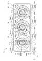
- FIG. 3is a front view showing the vehicle lamp 10 according to one embodiment.
- the first lamp unit 20, the second lamp unit 40, and the third lamp unit 60are horizontally arranged in a line.
- the direction indicated by Xis the "forward" direction of the vehicle lamp 10 (also the “frontward direction” of the vehicle), and the direction indicated by Y is the “leftward direction” orthogonal to the “forward” direction ( Although the vehicle is “leftward”, it is “rightward” when viewed from the front of the lamp), and the direction indicated by Z is “upward”.
- Xis the "forward” direction of the vehicle lamp 10 (also the "frontward direction” of the vehicle)
- the direction indicated by Yis the “leftward direction” orthogonal to the “forward” direction (although the vehicle is “leftward”, it is “rightward” when viewed from the front of the lamp), and the direction indicated by Z is “upward”.
- Xis the "forward” direction of the vehicle lamp 10 (also the "frontward direction” of the vehicle)
- Yis the “leftward direction” orthogonal to the "forward” direction (although the vehicle is “leftward”, it is “rightward” when viewed from the front of the lamp), and the direction indicated by Z is
- the vehicle lamp 10is a headlamp provided at the front end of a vehicle, and includes a lamp body 12 and a translucent cover 14 attached to the front opening of the lamp body 12.
- a projector-type first lamp unit 20, a second lamp unit 40, and a third lamp unit 60are incorporated in a lamp chamber formed by the above.
- the vehicular lamp 10forms a light distribution pattern for low beam with the light emitted from the first lamp unit 20 and the second lamp unit 40, and adds the light emitted from the third lamp unit 60 for high beam. It is configured to form a light distribution pattern.
- FIG. 4is a perspective view of the first lamp unit 20.
- FIG. FIG. 5is a cross-sectional view of the first lamp unit 20 (cross-sectional view taken along line II-II in FIG. 3).
- FIG. 6is a cross-sectional view of the first lamp unit 20 (cross-sectional view along line III-III in FIG. 3).
- the first lamp unit 20is configured to irradiate the light emitted from the light emitting element 22 through the translucent member 24 toward the front of the lamp.
- the light-emitting element 22is a white light-emitting diode having a rectangular (for example, square) light-emitting surface 22a. This substrate 26 is supported by the lamp body 12 .
- the light emitting element 22is arranged in the vicinity above the axis Ax extending in the longitudinal direction of the lamp, with the lower edge of the light emitting surface 22a extending in the horizontal direction.
- the translucent member 24is made of a transparent synthetic resin molded product such as acrylic resin.
- the translucent member 24is arranged in front of the lamp fixture of the light emitting element 22 and supported by the lamp body 12 via a support structure (not shown).
- the light-transmitting member 24includes a direct light control unit 24A that directly emits the light from the light-emitting element 22 that has entered the light-transmitting member 24 toward the front of the lamp, and the light from the light-emitting element 22 that has entered the light-transmitting member 24. It has a total reflection control section 24B that emits the light toward the front of the lamp after being totally reflected.
- the direct light control portion 24Ais set as a circular area centered on the axis line Ax when viewed from the front of the lamp.
- a rear surface 24Ab of the direct light control section 24Ais formed of a convex curved surface with the axis Ax as the center.
- the direct light control section 24Adirects the emitted light from the light emission center of the light emitting element 22 on the rear surface 24Ab as a slightly downward parallel light and makes it enter.
- the total reflection control section 24Bis an area located on the outer peripheral side of the direct light control section 24A, and is set as an annular area centered on the axis line Ax when viewed from the front of the lamp.
- the rear surface 24Bb of the total reflection control unit 24Bincludes an incident surface 24Bb1 that refracts the light emitted from the light emitting element 22 in a direction away from the axis Ax and enters the incident light from the incident surface 24Bb1 toward the front of the lamp. and a total reflection surface 24Bb2 for total reflection.
- the incident surface 24Bb1is configured by a conical surface that is close to a cylindrical surface centered on the axis Ax.
- the total reflection surface 24Bb2is formed of a curved surface having a convex rotating curved surface centered on the axis Ax as a reference surface.
- the total reflection control section 24Bis configured to reflect the light from the light emission center of the light emitting element 22 incident from the incident surface 24Bb1 as slightly downward parallel light on the total reflection surface 24Bb2.
- the total reflection surface 24Bb2 of the total reflection control section 24Bis divided into eight reflection areas L1, L2, L3, L4, R1, R2, R3 and R4 in the circumferential direction around the axis Ax.
- these eight reflective areas L1 to L4 and R1 to R4have the same size fan-shaped outer shape centered on the axis Ax when viewed from the front of the lamp, and have a vertical plane including the axis Ax. are arranged in a symmetrical positional relationship on both the left and right sides of the
- These eight reflection areas L1 to L4 and R1 to R4have slightly different values for the light reflection angles in the vertical direction for each reflection area.
- Each of the regions L1 to L4 and each of the reflective regions R1 to R4has a symmetrical surface shape.
- the emission surface 24a of the translucent member 24is composed of three concentrically divided emission areas 24aA, 24aB, and 24aC when viewed from the front of the lamp.
- the emission area 24aA located in the centeris a circular area centered on the axis line Ax when viewed from the front of the lamp, and its diameter is slightly larger than the diameter of the inner peripheral edge of the total reflection surface 24Bb2 of the total reflection control part 24B. is set to
- the emission area 24aB adjacent to the outer peripheral side of the emission area 24aAis formed as an annular area displaced toward the front side of the lamp with respect to the emission area 24aA. Further, the emission area 24aC adjacent to the outer peripheral side of the emission area 24aB is formed as an annular area displaced toward the front side of the lamp with respect to the emission area 24aB.
- a plurality of horizontal diffusion lens elements 24sA, 24sB, and 24sCare formed in each of the emission areas 24aA to 24aC to horizontally diffuse the light from the light emitting elements 22 reaching the emission areas 24aA to 24aC.
- Each of the horizontal diffusion lens elements 24sA to 24sCis formed in the shape of a convex cylindrical lens extending in the vertical direction, and is configured to diffuse the light from the light emitting element 22 evenly in the horizontal direction.
- the diffusion angle of the horizontal diffusion lens element 24sA formed in the emission area 24aAis set to a larger value than the diffusion angle of the horizontal diffusion lens element 24sB formed in the emission area 24aB. Also, the diffusion angle of the horizontal diffusion lens element 24sB formed in the emission region 24aB is set to a larger value than the diffusion angle of the horizontal diffusion lens element 24sC formed in the emission region 24aC.
- the second lamp unit 40has substantially the same optical configuration as the first lamp unit 20 .
- FIG. 7is a cross-sectional view of the second lamp unit 40 (cross-sectional view taken along line IV-IV in FIG. 3). As shown in FIG. 7, the second lamp unit 40 is also configured to irradiate the light emitted from the light emitting element 42 toward the front of the lamp via the translucent member 44 .
- the second lamp unit 40rotates the first lamp unit 20 clockwise (counterclockwise when the lamp is viewed from the front) about an axis Ax extending in the longitudinal direction of the lamp. 15°), and the light emitting surface 44a of the translucent member 44 has a configuration partially different from that of the lamp unit 20. As shown in FIG. 3, the second lamp unit 40 rotates the first lamp unit 20 clockwise (counterclockwise when the lamp is viewed from the front) about an axis Ax extending in the longitudinal direction of the lamp. 15°), and the light emitting surface 44a of the translucent member 44 has a configuration partially different from that of the lamp unit 20. As shown in FIG.
- the light-emitting element 42 of the second lamp unit 40also has the same configuration as the light-emitting element 22 of the first lamp unit 20, and is mounted on the substrate 46 in the vicinity above the axis line Ax and directed forward of the lamp. are placed.
- the light-transmitting member 44 of the second lamp unit 40also has a direct light control part 44A that directly emits the light from the light-emitting element 42 that has entered the light-transmitting member 44 toward the front of the lamp, and the light-transmitting member 44. It has a total reflection control section 44B that emits the light from the light emitting element 42 toward the front of the lamp after being totally reflected.
- the rear surface 44Ab of the direct light control section 44A and the rear surface 44Bb of the total reflection control section 44Bhave the same shape as the first lamp unit 20, but are rotated clockwise by 15°.
- the emission surface 44a of the translucent member 44is composed of three emission areas 44aA, 44aB, and 44aC that are concentrically divided when viewed from the front of the lamp.
- 44aCis formed with a plurality of oblique diffusion lens elements 44sA, 44sB, and 44sC that diffuse the light emitted from the translucent member 44 in an oblique direction that is 15° with respect to the horizontal direction.
- Each of the oblique diffusion lens elements 44sA to 44sCis formed in the shape of a convex cylindrical lens extending in a direction perpendicular to the oblique direction, and is configured to evenly diffuse the light from the light emitting element 42 in the oblique direction.
- the diffusion angles of the oblique diffusion lens elements 44sA to 44sCare set to values smaller than the diffusion angles of the horizontal diffusion lens elements 24sA to 24sC in the lamp unit 20 (for example, about half the value).
- the diffusion angle of the oblique diffusion lens element 44sAis set to a value larger than the diffusion angle of the oblique diffusion lens element 44sB, and the diffusion angle of the oblique diffusion lens element 44sB is set to be larger than the diffusion angle of the oblique diffusion lens element 44sC. is set to a large value.
- the third lamp unit 60is also configured to irradiate the light emitted from the light emitting element 62 toward the front of the lamp via the translucent member 64. .
- the basic configuration of the third lamp unit 60is substantially the same as that of the second lamp unit 40.
- the light emitting surface 64a of the light transmitting member 64is composed of three concentrically divided light emitting areas 64aA, 64aB, and 64aC when viewed from the front of the lamp.
- a plurality of oblique diffusion lens elements 64sA, 64sB, and 64sCare formed to diffuse the emitted light in oblique directions that are 15° with respect to the horizontal direction.
- Each of the oblique diffusion lens elements 64sA to 64sCis formed in the shape of a convex cylindrical lens extending in a direction orthogonal to the oblique direction, and is configured to evenly diffuse the light from the light emitting element 62 in the oblique direction.
- the diffusion angles of the oblique diffusion lens elements 64sA to 64sCare approximately the same as the diffusion angles of the oblique diffusion lens elements 44sA to 44sC in the second lamp unit 40, and the diffusion angles of the horizontal diffusion lens elements 24sA to 24sC in the lamp unit 20. is set to a value smaller than (for example, about half the value).
- the diffusion angle of the oblique diffusion lens element 64sAis set to a value larger than the diffusion angle of the oblique diffusion lens element 64sB, and the diffusion angle of the oblique diffusion lens element 64sB is set to a value larger than the diffusion angle of the oblique diffusion lens element 64sC. is set to
- FIGS. 8A and 8Bare perspective views of a light distribution pattern formed on a virtual vertical screen placed 25 m in front of the vehicle by light emitted from the vehicle lamp 10 toward the front of the lamp.
- 2Ashows a low-beam light distribution pattern PL1
- FIG. 2Bshows a high-beam light distribution pattern PH1.
- a low-beam light distribution pattern PL1 shown in FIG. 8(a)is a low-beam light distribution pattern for left light distribution, and has horizontal and oblique cutoff lines CL1 and CL2 at its upper edge.
- the cutoff lines CL1 and CL2are formed as a horizontal cutoff line CL1 on the opposite lane side portion on the right side of the line VV passing vertically through the vanishing point HV in the front direction of the lamp and the line VV.
- a diagonal cutoff line CL2is formed on the left side of the vehicle lane side, and an elbow point E, which is the intersection of the two, is located below HV by about 0.5 to 0.6°.
- the low-beam light distribution pattern PL1is a composite light distribution of a light distribution pattern PA1 formed by the light emitted from the first lamp unit 20 and a light distribution pattern PB1 formed by the light emitted from the second lamp unit 40. formed as a pattern.
- the light distribution pattern PA1is a horizontally long light distribution pattern that spreads in the left-right direction around the VV line, and the upper edge of the light distribution pattern PA1 forms a horizontal cutoff line CL1 of the low-beam light distribution pattern PL1. .
- the portion located to the lower left of the elbow point E where the high-luminance region of the light distribution pattern PA1 and the high-luminance region of the light distribution pattern PB1 overlapconstitutes the high-luminance region.
- the light distribution pattern PB1 shown in FIG. 8Ais a horizontally elongated light distribution pattern that spreads in an oblique direction that is inclined clockwise by 15° with respect to the horizontal direction.
- a cutoff line CL2is formed.
- a high-beam light distribution pattern PH1 shown in FIG. 8(b)is formed by adding a light distribution pattern PC1 to the low-beam light distribution pattern PL1.
- the light distribution pattern PC1is a light distribution pattern formed by the light emitted from the third lamp unit 60.
- the light distribution pattern PC1is a horizontally long light distribution pattern that extends in an oblique direction that is inclined clockwise by 15° with respect to the horizontal direction, and the lower end edge of the light distribution pattern PC1 extends along the oblique cutoff line CL2 of the low-beam light distribution pattern PL1. formed.
- 9 to 11are diagrams for explaining the formation process of the light distribution pattern PA1.
- FIG. 9(c)is a diagram showing a light distribution pattern PA1A formed by the light emitted from the direct light control section 64A in the light distribution pattern PA1.
- This light distribution pattern PA1Ais a horizontally elongated light distribution pattern formed by expanding the light distribution pattern PA1A Ann shown in FIG. 9(b) to both the left and right sides.
- the light distribution pattern PA1A.Ois the same as that of the direct light controller 24A when it is assumed that the plurality of horizontal diffusing lens elements 24sA to 24sC are not formed on the light emitting surface 24a of the translucent member 24. is a light distribution pattern formed by light emitted from the
- This light distribution pattern PA1A®is formed as a light distribution pattern having a substantially square outer shape below the HH line passing through HV in the horizontal direction. A boundary is formed. This is because the lower edge of the light emitting surface 22a of the light emitting element 22 extends horizontally above the axis Ax, and the direct light control portion 24A of the translucent member 24 controls the light emission of the light emitting element 22 on the rear surface 24Ab. This is because the light emitted from the center is made to enter as parallel light directed slightly downward.
- the light distribution pattern PA1A formed by the emitted light from the direct light control section 24Ais as shown in FIG. As shown in (c), it is formed as a horizontally elongated light distribution pattern, and a clear light-dark boundary line CLa extending in the horizontal direction is formed at the upper end edge thereof.
- FIG. 10is formed by emitted light from the right half area of the total reflection control section 24B, assuming that the plurality of horizontal diffusion lens elements 24sA to 24sC are not formed on the emission surface 24a of the translucent member 24. It is a light distribution pattern.
- a light distribution pattern PA1B1' shown in FIG. 10(b1)is a light distribution pattern formed by reflected light from the reflection region R1 shown in FIG. 10(a1).
- This light distribution pattern PA1B1may be formed as a slightly oblong light distribution pattern that straddles the VV line.
- the upper region thereofis relatively bright, and a light-dark boundary line extending substantially horizontally is formed at the upper edge.
- a light distribution pattern PA1B2? shown in Fig. 10(b2)is a light distribution pattern formed by reflected light from the reflection region R2 shown in Fig. 10(a2).
- This light distribution pattern PA1B2is formed as a slightly vertically elongated light distribution pattern that straddles the line VV.
- the upper region thereofis relatively bright, and a light-dark boundary line extending in a substantially horizontal direction is formed at the upper edge.
- a light distribution pattern PA1B3? shown in Fig. 10(b3)is a light distribution pattern formed by reflected light from the reflection region R3 shown in Fig. 10(a3).
- This light distribution pattern PA1B3is formed as a slightly vertically elongated light distribution pattern that straddles the line VV.
- the upper region thereofis relatively bright, and a light-dark boundary line extending in a substantially horizontal direction is formed at the upper edge.
- a light distribution pattern PA1B4' shown in FIG. 10(b4)is a light distribution pattern formed by reflected light from the reflection region R4 shown in FIG. 10(a4).
- This light distribution pattern PA1B4may be formed as a slightly oblong light distribution pattern that straddles the line VV.
- the upper region thereofis relatively bright, and a light-dark boundary line extending in a substantially horizontal direction is formed at the upper edge.
- each of the reflection regions R1 to R4is set so that the upper edge of each of the light distribution patterns PA1B1O to PA1B4 is at substantially the same height position as the upper edge of the light distribution pattern PA1A shown in FIG. 9C. It is
- the light distribution pattern PB1 formed by the light emitted from the entire reflection control section 24Bincludes the four light distribution patterns PA1B1 réelle to PA1B4 owned shown in FIGS.
- the light patternis formed as a horizontally elongated light distribution pattern extending to both the left and right sides, and a relatively clear light-dark boundary line CLb is formed at the upper edge of the light pattern.
- a horizontal cutoff line CL1 of the low beam light distribution pattern PL1is formed by the light/dark boundary line CLa of the light distribution pattern PA1A and the light/dark boundary line CLb of the light distribution pattern PA1B.
- FIG. 12is a diagram for explaining the formation process of the light distribution pattern PB1 shown in FIG. 8(a).
- This light distribution pattern PB1is formed as a combined light distribution pattern of the light distribution pattern PB1A shown in FIG. 12(b1) and the light distribution pattern PB1B shown in FIG. 12(b2).
- the light distribution pattern PB1Ais a light distribution pattern formed by emitted light from the direct light control portion 44A of the translucent member 44 shown in FIG.
- the light distribution patternis formed as a horizontally long light distribution pattern that spreads out into a wide area, and a clear light-dark boundary line CLc extending in an oblique direction is formed at the upper edge of the light distribution pattern.
- the light distribution pattern PB1Bis a light distribution pattern formed by the emitted light from the total reflection control portion 44B of the translucent member 44 shown in FIG. 12(a2), and as shown in FIG. A light-dark boundary line CLd extending obliquely is formed at the upper edge of the light distribution pattern.
- These light-dark boundary lines CLc and CLdform an oblique cutoff line CL2 of the low-beam light distribution pattern PL1.
- the light distribution pattern PC1is formed in the same manner as the light distribution pattern PB1 by the third lamp unit 60 having the same configuration as the second lamp unit 40.
- the light distribution pattern PC1may be obtained by rotating the light distribution pattern PB1 about the elbow point by 180 degrees.
- the light-transmitting member 64 of the third lamp unit 60 and the light-transmitting member 44 of the second lamp unit 40have the same optical structure, and the light-transmitting member 64 is positioned relative to the light-transmitting member 44 when viewed from the front. , may be mounted in a state rotated 180 degrees.
- the light distribution pattern PC1 and the light distribution pattern PB1may have a line-symmetrical relationship with respect to the oblique cutoff line CL2.
- the light-transmitting member 64 of the third lamp unit 60 and the light-transmitting member 44 of the second lamp unit 40have the same optical structure, and the light-transmitting member 64 is positioned relative to the light-transmitting member 44 when viewed from the front. , may be mounted upside down.
- the vehicular lamp 10includes a first lamp unit 20 and a second lamp unit 40.
- Translucent members 24, 44 of the respective light-transmitting members 24, 44emit light from the light-emitting elements 22 incident on the translucent members 24, 44. , 42 directly toward the front of the lamp, and the light from the light emitting elements 22 and 42 incident on the translucent members 24 and 44 are totally reflected and then directed toward the front of the lamp. Since the total reflection control units 24B and 44B are provided, it is possible to emit most of the emitted light from the light emitting elements 22 and 42 from the translucent members 24 and 44 toward the front of the lamp. It is possible to improve the utilization efficiency of the luminous flux of the light source.
- the total reflection surface 24Bb2 of the total reflection control portion 24B in the light transmission member 24 of the first lamp unit 20is formed into eight reflection areas L1, L2, L3, and L4 in the circumferential direction around the direct light control portion 24A.
- R1, R2, R3, and R4the light distribution patterns PA1B1®, PA1B2®, PA1B3®, PA1B4®, etc. formed by the reflected light from the respective reflection areas L1 to L4 and R1 to R4 should be aligned. is easily possible.
- the total reflection surface 44Bb2 of the total reflection control part 44B of the light transmission member 44has the same configuration as the light transmission member 24 of the first lamp unit 20. It is possible to easily align the upper end positions of the light distribution pattern formed by the reflected light from the reflection area.
- a plurality of horizontal diffusion lens elements 24sA, 24sB, and 24sC for horizontally diffusing light emitted from the light transmitting member 24are formed on the light emitting surface 24a of the light transmitting member 24 of the first lamp unit 20.
- a plurality of oblique diffusing lens elements 44sA and 44sB for diffusing light emitted from the translucent member 44 in an oblique direction with respect to the horizontal directionare provided on the emission surface 44a of the translucent member 44 of the second lamp unit 40.
- the utilization efficiency of the light source luminous fluxis With improvement, a bright low-beam light distribution pattern PL1 having horizontal and oblique cutoff lines CL1 and CL2 at the upper edge can be formed.
- the translucent member 24 of the first lamp unit 20has the diffusion angle of the horizontal diffusion lens element 24sA formed in the emission area 24aA, which is the emission surface of the direct light control section 24A.
- 24Bwhich are the emission surfaces of 24B, are set to a value larger than the diffusion angle of the horizontal diffusion lens elements 24sB and 24sC formed in the emission areas 24aB and 24aC.
- the diffusion angle of the oblique diffusion lens element 44sA formed in the emission area 44aA, which is the emission surface of the direct light control section 44Ais the same as that of the oblique diffusion lens elements 44sB formed in the emission areas 44aB, 44aC, which are the emission surfaces of the total reflection control section 44B. , 44 sC, the following effects can be obtained.
- the light distribution pattern PA1Ais larger than the light distribution patterns PA1B1' to PA1B4' formed by the light emitted from the total reflection control units 24B and 44B.
- the diffusion angles of the horizontal diffusion lens elements 24sA and the oblique diffusion lens elements 44sA formed in the emission regions 24aA and 44aA constituting the emission surfaces of the direct light control units 24A and 44Aare set to the emission surfaces of the total reflection control units 24B and 44B.
- the light distribution patterns PA1 and PB1 formed by the light emitted from the second lamp unit 40can be formed as light distribution patterns with little light distribution unevenness.
- the translucent member 24 of the first lamp unit 20has an output surface of the total reflection control portion 24B, which has an output area 24aB (inner circumferential annular area) and an output area 24aC (outer circumferential annular area).
- the diffusion angle of the horizontal diffusion lens element 24sB formed in the emission region 24aBis set to a larger value than the diffusion angle of the horizontal diffusion lens element 24sC formed in the emission region 24aC.
- the light-transmitting member 44 of the lamp unit 40has a total reflection control portion 44B of which the output surface is divided into an output area 44aB (inner peripheral side annular area) and an output area 44aC (outer peripheral side annular area).
- the diffusion angle of the oblique diffusion lens element 44sB formed in the light emitting area 44aCis set to a larger value than the diffusion angle of the oblique diffusion lens element 44sC formed in the emission area 44aC, the following effects can be obtained. .
- the light distribution pattern formed by the light emitted from the emission regions 24aB and 44aBis larger than the light distribution pattern formed by the light emitted from the emission regions 24aC and 44aC.
- the light distribution patterns PA1 and PB1 formed by the light emitted from the first lamp unit 20 and the second lamp unit 40can be formed as light distribution patterns with little light distribution unevenness.
- the light transmitting members 24 and 44 of the first lamp unit 20 and the second lamp unit 40are configured so that the emission areas 24aB and 44Ba forming the emission surfaces of the total reflection control units 24B and 44B are the direct light control units 24A and 44B.
- the emission areas 24aA and 44aA forming the emission surfaces of the total reflection control sections 24C and 44Care shifted toward the front side of the lamp with respect to the emission areas 24aA and 44aA forming the emission surfaces of the total reflection control sections 24C and 44C. , 44B, the thickness of the translucent members 24 and 44 can be reduced.
- the vehicle lamp 10by adding the irradiation light from the third lamp unit 60 having substantially the same configuration as the first lamp unit 20 and the second lamp unit 40, the high beam light distribution is achieved. Since it is configured to form the pattern PH1, it is possible to exhibit the function as a headlamp while ensuring uniformity in design.
- the third lamp unit 60is configured in the same manner as the second lamp unit 40, and the light distribution pattern PC1 has the same characteristics as the light distribution pattern PB1.
- the top edge of pattern PB1can be perfectly coincident, or the two light distributions can be slightly overlapped. As a result, the overlap between the light distribution pattern PC1 and the low beam light distribution region PL1 can be reduced, and the energy of the light distribution pattern PC1 can be concentrated on a distant area to be irradiated in the high beam mode.
- FIG. 13is an exploded perspective view showing a configuration example of the vehicle lamp 10.
- the vehicle lamp 10includes an electric system unit 200 in which an electric circuit is modularized, and an optical system unit 300 in which an optical system is mounted.
- the first lamp unit 20is located in the center
- the second lamp unit 40is arranged on the vehicle center side
- the third lamp unit 60is arranged on the outside of the vehicle.
- the electric system unit 200is also called an LED assembly.
- the electrical system unit 200includes a substrate 210, and the light emitting elements 22, 42, and 62 of the first lamp unit 20, the second lamp unit 40, and the third lamp unit 60 are mounted on the common substrate 210 for their lighting circuits. 220 and a connector 230 are mounted.
- the optical systems of the first lamp unit 20, the second lamp unit 40, and the third lamp unit 60that is, the translucent members 24, 44, and 64 are mounted in the optical system unit 300, and are mounted on the electrical system unit 200. It is removable.
- FIG. 14(a) and (b)are a sectional view and a front view of the optical system unit 300.
- FIG. The optical system unit 300has a lens unit 310 and a lens holder 320 .
- the lens unit 310is obtained by integrally molding the translucent members 24, 44, 64 using transparent synthetic resin such as acrylic resin. Lens unit 310 is fixed to lens holder 320 , and lens holder 320 is fixed to substrate 210 of electrical system unit 200 .
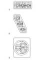
- FIG. 15is an exploded perspective view showing a modification of the vehicle lamp 10.
- FIG. 15is an exploded perspective view showing a modification of the vehicle lamp 10.
- three lamp units 20, 40, 60are arranged non-linearly.
- the three lamp units 20, 40, and 60are arranged such that their respective centers are positioned at the vertices of a virtual triangle when the vehicle lamp 10 is viewed from the front.
- the translucent members 24, 44, 46may be arranged so that their outer circles circumscribe each other.
- the light emitting elements 22, 42, 62are arranged on the substrate 210 so as to form vertices of an equilateral triangle.
- the first lamp unit 20is arranged on the lower side, and the second lamp unit 40 and the third lamp unit 60 are arranged on the upper side, but their positions may be interchanged.
- FIG. 16(a) to (c)are diagrams showing a vehicle lamp 10 according to a modification.
- FIG. 16(a)shows the configuration of FIG. 15 turned upside down.
- the first lamp unit 20, the second lamp unit 40, and the third lamp unit 60may be arranged on an oblique straight line as shown in FIG. 16(b), or as shown in FIG. It may be arranged vertically.
- the total reflection surface 24Bb of the total reflection control portion 24B in the translucent member 24has been described as being divided into eight reflection areas L1 to L4 and R1 to R4. It is also possible to have a configuration divided into reflective areas.
- each of the horizontal diffusion lens elements 24sA to 24sC, 44sA to 44sC, and 64sA to 64sChas been described as being formed in the shape of a convex cylindrical lens, but these elements are formed in the shape of a concave cylindrical lens. is also possible.
- the total reflection surfaces 24Bb, 44Bb, 64Bb of the total reflection control units 24B, 44B, 64B in the translucent members 24, 44, 64are composed of a curved surface of rotation or a curved surface with the curved surface of rotation as a reference surface. Although it has been described as a single object, it is also possible to use a curved surface other than this or a structure composed of a plurality of planes.
- the emission surfaces 24a, 44a, 64a of the light transmitting members 24, 44, 64are concentrically divided when viewed from the front of the lamp. shape, etc.).
- the present disclosurerelates to vehicle lamps.
Landscapes
- Engineering & Computer Science (AREA)
- General Engineering & Computer Science (AREA)
- Physics & Mathematics (AREA)
- Microelectronics & Electronic Packaging (AREA)
- Optics & Photonics (AREA)
- Non-Portable Lighting Devices Or Systems Thereof (AREA)
Abstract
Description
Translated fromJapanese本開示は、車両用灯具に関する。The present disclosure relates to vehicle lamps.
従来より、車両用灯具の構成として、発光素子からの出射光を透光部材を介して灯具前方へ向けて照射するように構成された灯具ユニットを有するものが知られている。Conventionally, as a configuration of a vehicle lamp, there has been known a lamp unit configured to irradiate light emitted from a light-emitting element toward the front of the lamp via a translucent member.
特許文献1には、このような車両用灯具の灯具ユニットにおける透光部材の構成として、透光部材に入射した発光素子からの光を灯具前方へ向けて直接出射させる直射光制御部と、透光部材に入射した発光素子からの光を全反射させた後に灯具前方へ向けて出射させる全反射制御部とを備えたものが記載されている。
また特許文献2には、このような透光部材の構成として、その全反射制御部の全反射面が直射光制御部の周囲において周方向に複数の反射領域に区分けされたものが記載されている。Further, Patent Document 2 describes a configuration of such a translucent member in which the total reflection surface of the total reflection control portion is divided into a plurality of reflection areas in the circumferential direction around the direct light control portion. there is
特許文献1に記載された灯具ユニットのように、その透光部材として直射光制御部と全反射制御部とを備えた構成を採用することにより、発光素子からの出射光の多くを透光部材から灯具前方へ向けて出射させることが可能となり、これにより光源光束の利用効率向上を図ることが可能となる。As in the lighting unit described in
その際、特許文献2に記載されているような透光部材を採用することにより、その全反射制御部の全反射面を構成する各反射領域からの反射光によって形成される配光パターンの上端位置を揃えることが可能となり、これにより全反射制御部からの出射光によって形成される配光パターンとして上端縁にカットオフラインを有する配光パターンを形成することが可能となる。At that time, by adopting a light-transmitting member as described in Patent Document 2, the upper end of the light distribution pattern formed by the reflected light from each reflection area constituting the total reflection surface of the total reflection control unit It is possible to align the positions, thereby forming a light distribution pattern having a cut-off line at the upper edge as a light distribution pattern formed by the light emitted from the total reflection control section.
本開示は係る状況においてなされたものであり、そのある態様の例示的な目的のひとつは、ハイビームとロービームを切りかえ可能な車両用灯具を提供することにある。The present disclosure has been made in such a situation, and one exemplary purpose of certain aspects thereof is to provide a vehicle lamp capable of switching between high beam and low beam.
本開示のある態様は、ロービームモードとハイビームモードが切りかえ可能な車両用灯具に関する。車両用灯具は、ロービームモードおよびハイビームモードにおいて、ロービームモードおよびハイビームモードにおいて、水平方向に対して平行な方向を長手とする領域であって、その上端縁が水平カットオフラインを形成する第1領域を照射する第1灯具ユニットと、水平方向に対して傾斜した方向を長手とする領域であって、その上端縁が斜めカットオフラインを形成する第2領域を照射する第2灯具ユニットと、ハイビームモードにおいて、水平方向に対して傾斜した方向を長手とする領域であって、その下端縁が斜めカットオフラインと平行である第3領域を照射する第3灯具ユニットと、を備える。A certain aspect of the present disclosure relates to a vehicle lamp that can switch between a low beam mode and a high beam mode. In the low beam mode and the high beam mode, the vehicular lamp has a first area having a longitudinal direction parallel to the horizontal direction and having an upper edge forming a horizontal cutoff line in the low beam mode and the high beam mode. a first lamp unit for irradiating, a second lamp unit for irradiating a second area having a longitudinal direction inclined with respect to the horizontal direction, the upper edge of which forms an oblique cut-off line, and a high beam mode. and a third lamp unit for illuminating a third area having a longitudinal direction inclined with respect to the horizontal direction and having a lower edge parallel to the oblique cutoff line.
本開示のある態様によれば、ハイビームとロービームを切りかえ可能な車両用灯具を提供できる。According to an aspect of the present disclosure, it is possible to provide a vehicle lamp that can switch between high beam and low beam.
(実施形態の概要)
本開示のいくつかの例示的な実施形態の概要を説明する。この概要は、後述する詳細な説明の前置きとして、実施形態の基本的な理解を目的として、1つまたは複数の実施形態のいくつかの概念を簡略化して説明するものであり、発明あるいは開示の広さを限定するものではない。この概要は、考えられるすべての実施形態の包括的な概要ではなく、すべての実施形態の重要な要素を特定することも、一部またはすべての態様の範囲を線引きすることも意図していない。便宜上、「一実施形態」は、本明細書に開示するひとつの実施形態(実施例や変形例)または複数の実施形態(実施例や変形例)を指すものとして用いる場合がある。(Overview of embodiment)
SUMMARY OF THE INVENTION Several exemplary embodiments of the disclosure are summarized. This summary presents, in simplified form, some concepts of one or more embodiments, as a prelude to the more detailed description that is presented later, and for the purpose of a basic understanding of the embodiments. The size is not limited. This summary is not a comprehensive overview of all possible embodiments, and it is intended to neither identify key elements of all embodiments nor delineate the scope of some or all aspects. For convenience, "one embodiment" may be used to refer to one embodiment (example or variation) or multiple embodiments (examples or variations) disclosed herein.
一実施形態に係る車両用灯具は、ロービームモードとハイビームモードが切りかえ可能であり、ロービームモードおよびハイビームモードにおいて、ロービームモードおよびハイビームモードにおいて、水平方向に対して平行な方向を長手とする領域であって、その上端縁が水平カットオフラインを形成する第1領域を照射する第1灯具ユニットと、水平方向に対して傾斜した方向を長手とする領域であって、その上端縁が斜めカットオフラインを形成する第2領域を照射する第2灯具ユニットと、ハイビームモードにおいて、水平方向に対して傾斜した方向を長手とする領域であって、その下端縁が斜めカットオフラインと平行である第3領域を照射する第3灯具ユニットと、を備える。A vehicular lamp according to one embodiment is switchable between a low beam mode and a high beam mode. a first lamp unit that irradiates a first region whose upper edge forms a horizontal cutoff line; and a third lighting unit that irradiates a second area in high beam mode, which is an area whose longitudinal direction is inclined with respect to the horizontal direction, and whose lower edge is parallel to the oblique cut-off line. and a third lamp unit.
ロービームモードでは、第1灯具ユニットにより、水平カットオフラインよりも下側を広範囲に照射し、第2灯具ユニットにより、斜めカットオフラインに沿った領域を照射することにより、ロービームに適した配光を形成できる。In low beam mode, the first lighting unit illuminates a wide area below the horizontal cutoff line, and the second lighting unit illuminates the area along the diagonal cutoff line, forming a light distribution suitable for low beams. can.
またハイビームモードでは、第3灯具ユニットによって、主として斜めカットオフラインより上側を占める第3領域を追加で照射することにより、ハイビームの配光を形成できる。In addition, in the high beam mode, a high beam light distribution can be formed by additionally irradiating the third region, which mainly occupies the upper side of the oblique cutoff line, with the third lamp unit.
「発光素子」の種類は特に限定されるものではなく、例えば発光ダイオードやレーザダイオード、有機EL(Electro Luminescence)素子などが採用可能である。The type of "light-emitting element" is not particularly limited, and for example, light-emitting diodes, laser diodes, organic EL (Electro Luminescence) elements, etc. can be adopted.
一実施形態において、第3領域の下端縁は、斜めカットオフラインと一致してもよい。第3領域の下端縁は、斜めカットオフラインより下側に位置していてもよく、第2領域と第3領域はオーバーラップしてもよい。In one embodiment, the bottom edge of the third region may coincide with the oblique cutoff line. A lower edge of the third region may be positioned below the diagonal cutoff line, and the second region and the third region may overlap.
一実施形態において、第1領域の長手方向の長さは、第2領域および第3領域の長手方向の長さよりも長くてもよい。In one embodiment, the longitudinal length of the first region may be longer than the longitudinal lengths of the second and third regions.
一実施形態において、第1灯具ユニットおよび第2灯具ユニットの少なくとも一方のハイビームモードにおける照度は、ロービームモードにおける照度より低くてもよい。ハイビームモードにおいて、第1灯具ユニットおよび第2灯具ユニットの少なくとも一方を暗くすることで、ハイビームモードにおいて、第3灯具ユニットを追加点灯させたことによる消費電力および発熱の増加を相殺することができる。In one embodiment, the illuminance in the high beam mode of at least one of the first lamp unit and the second lamp unit may be lower than the illuminance in the low beam mode. By darkening at least one of the first lamp unit and the second lamp unit in the high beam mode, it is possible to offset an increase in power consumption and heat generation due to additional lighting of the third lamp unit in the high beam mode.
一実施形態において、第1灯具ユニットから第3灯具ユニットは実質的に同じ光学的な構成を有してもよい。In one embodiment, the first to third lamp units may have substantially the same optical configuration.
一実施形態において、第1灯具ユニットから第3灯具ユニットはそれぞれ、発光素子と、発光素子の出射光を灯具前方へ向けて照射する透光部材と、を備えてもよい。透光部材は、透光部材に入射した発光素子からの光を灯具前方へ向けて直接出射させる直射光制御部と、透光部材に入射した発光素子からの光を全反射させた後に灯具前方へ向けて出射させる全反射制御部と、を備えており、全反射制御部の全反射面は、直射光制御部の周囲において周方向に複数の反射領域に区分けされており、透光部材の出射面には、透光部材からの出射光を所定方向に拡散させる複数の拡散レンズ素子が形成されていてもよい。In one embodiment, each of the first to third lamp units may include a light-emitting element and a translucent member that emits light emitted from the light-emitting element toward the front of the lamp. The light-transmitting member includes a direct light control unit that directly emits light from the light-emitting element that has entered the light-transmitting member toward the front of the lamp, and a direct light control unit that directly emits the light from the light-emitting element that has entered the light-transmitting member toward the front of the lamp. and a total reflection control section that emits light toward the direct light control section. A plurality of diffuser lens elements may be formed on the exit surface to diffuse the light emitted from the translucent member in a predetermined direction.
この構成によれば、発光素子からの出射光の多くを透光部材から灯具前方へ向けて出射させることが可能となり、これにより光源光束の利用効率を向上させることが可能となる。According to this configuration, most of the emitted light from the light emitting element can be emitted from the translucent member toward the front of the lamp, thereby improving the utilization efficiency of the luminous flux of the light source.
その際、第1および第2灯具ユニットの各々は、その透光部材における全反射制御部の全反射面が、直射光制御部の周囲において周方向に複数の反射領域に区分けされているので、各反射領域からの反射光によって形成される配光パターンの上端位置を揃えることが容易に可能となる。At this time, in each of the first and second lamp units, the total reflection surface of the total reflection control portion in the translucent member is divided into a plurality of reflection areas in the circumferential direction around the direct light control portion. It is possible to easily align the upper end positions of the light distribution patterns formed by the reflected light from the respective reflection areas.
一実施形態において、第1灯具ユニットの複数の拡散レンズ素子は、正面視したときに水平方向に配列され、第2灯具ユニットおよび第3灯具ユニットの複数の拡散レンズ素子は、正面視したときに斜め方向に配列していてもよい。In one embodiment, the plurality of diffuser lens elements of the first lamp unit are arranged horizontally when viewed from the front, and the plurality of diffuser lens elements of the second lamp unit and the third lamp unit are arranged horizontally when viewed from the front. They may be arranged obliquely.
つまり、第1灯具ユニットの透光部材の出射面には、透光部材からの出射光を水平方向に拡散させる複数の水平拡散レンズ素子が形成されるとともに、第2灯具ユニットの透光部材の出射面には、透光部材からの出射光を水平方向に対して傾斜した斜め方向に拡散させる複数の斜め拡散レンズ素子が形成されているので、第1および第2灯具ユニットからの照射光によって上端縁に水平および斜めカットオフラインを有する明るい配光パターンを形成することが可能となる。また、第3灯具ユニットにも、水平方向に対して傾斜した斜め方向に拡散させる複数の斜め拡散レンズ素子を形成することで、斜めカットオフラインに沿った第3領域を好適に照射できる。That is, a plurality of horizontal diffusion lens elements for diffusing light emitted from the light transmitting member in the horizontal direction are formed on the emission surface of the light transmitting member of the first lamp unit, and the light transmitting member of the second lamp unit has a plurality of horizontal diffusion lens elements. A plurality of oblique diffusing lens elements are formed on the exit surface for diffusing the light emitted from the translucent member in oblique directions that are inclined with respect to the horizontal direction. It is possible to form a bright light distribution pattern with horizontal and diagonal cut-off lines at the upper edge. Further, by forming a plurality of oblique diffusion lens elements for diffusing light obliquely with respect to the horizontal direction also in the third lamp unit, the third area along the oblique cut-off line can be illuminated favorably.
一実施形態において、第1灯具ユニット、第2灯具ユニット、第3灯具ユニットそれぞれの透光部材は一体成形されていてもよい。In one embodiment, the translucent members of the first lamp unit, the second lamp unit, and the third lamp unit may be integrally molded.
一実施形態において、第1灯具ユニット、第2灯具ユニット、第3灯具ユニットそれぞれの発光素子およびそれらの点灯回路は、同一の基板上に実装されていてもよい。In one embodiment, the light emitting elements of the first lamp unit, the second lamp unit, and the third lamp unit and their lighting circuits may be mounted on the same substrate.
一実施形態において、第1灯具ユニットから第3灯具ユニットは、正面視したときに、それぞれの中心が仮想的な三角形の頂点に位置するように配置されてもよい。In one embodiment, the first to third lamp units may be arranged such that their respective centers are positioned at the vertices of a virtual triangle when viewed from the front.
一実施形態において、第1灯具ユニットから第3灯具ユニットは、正面視したときに同一直線上に配置されてもよい。In one embodiment, the first to third lamp units may be arranged on the same straight line when viewed from the front.
一実施形態において、第1灯具ユニットの透光部材を、その直射光制御部の出射面に形成された水平拡散レンズ素子の拡散角が全反射制御部の出射面に形成された水平拡散レンズ素子の拡散角よりも大きい値に設定された構成としてもよい。第2灯具ユニットの透光部材を、その直射光制御部の出射面に形成された斜め拡散レンズ素子の拡散角が全反射制御部の出射面に形成された斜め拡散レンズ素子の拡散角よりも大きい値に設定された構成としてもよい。In one embodiment, the translucent member of the first lamp unit is a horizontal diffusion lens element formed on the output surface of the direct light control section, and the diffusion angle of the horizontal diffusion lens element is formed on the output surface of the total reflection control section. may be set to a value larger than the diffusion angle of . The light-transmitting member of the second lamp unit is arranged such that the diffusion angle of the oblique diffusion lens element formed on the output surface of the direct light control section is larger than the diffusion angle of the oblique diffusion lens element formed on the output surface of the total reflection control section. It may be configured to be set to a large value.
この構成によれば、直射光制御部は全反射制御部よりも発光素子から近い位置にあるので、直射光制御部からの出射光により形成される配光パターンは、全反射制御部からの出射光により形成される配光パターンよりも大きい配光パターンとなる。そこで、直射光制御部の出射面に形成された水平拡散レンズ素子および斜め拡散レンズ素子の拡散角を、全反射制御部の出射面に形成された水平拡散レンズ素子および斜め拡散レンズ素子の拡散角よりも大きい値に設定することにより、第1および第2灯具ユニットからの照射光によって形成される配光パターンを配光ムラの少ない配光パターンとして形成することができる。According to this configuration, the direct light control section is located closer to the light emitting element than the total reflection control section. The light distribution pattern becomes larger than the light distribution pattern formed by the incident light. Therefore, the diffusion angles of the horizontal diffusion lens element and the oblique diffusion lens element formed on the output surface of the direct light control section are replaced by the diffusion angles of the horizontal diffusion lens element and the oblique diffusion lens element formed on the output surface of the total reflection control section. By setting a value larger than , the light distribution pattern formed by the light emitted from the first and second lamp units can be formed as a light distribution pattern with little light distribution unevenness.
一実施形態において、第1灯具ユニットの透光部材として、その全反射制御部の出射面が内周側環状領域と外周側環状領域とに区分けされた構成とした上で、内周側環状領域に形成された水平拡散レンズ素子の拡散角が外周側環状領域に形成された水平拡散レンズ素子の拡散角よりも大きい値に設定された構成とするとともに、第2灯具ユニットの透光部材として、その全反射制御部の出射面が内周側環状領域と外周側環状領域とに区分けされた構成とした上で、内周側環状領域に形成された斜め拡散レンズ素子の拡散角が外周側環状領域に形成された斜め拡散レンズ素子の拡散角よりも大きい値に設定された構成としてもよい。In one embodiment, as the translucent member of the first lamp unit, the emission surface of the total reflection control section is divided into an inner circumference side annular area and an outer circumference side annular area. The diffusion angle of the horizontal diffusion lens element formed in the second lamp unit is set to a larger value than the diffusion angle of the horizontal diffusion lens element formed in the outer circumferential annular region, and the translucent member of the second lamp unit includes: The emission surface of the total reflection control section is divided into an inner ring-shaped region and an outer ring-shaped region, and the diffusion angle of the oblique diffusion lens element formed in the inner ring-shaped region is the outer ring-shaped region. It may be configured to be set to a value larger than the diffusion angle of the oblique diffusion lens element formed in the region.
すなわち、内周側環状領域からの出射光により形成される配光パターンは、外周側環状領域からの出射光により形成される配光パターンよりも大きい配光パターンとなる。そこで、内周側環状領域に形成された水平および斜め拡散レンズ素子の拡散角を、外周側環状領域に形成された水平および斜め拡散レンズ素子の拡散角よりも大きい値に設定することにより、第1および第2灯具ユニットからの照射光によって形成される配光パターンを配光ムラの少ない配光パターンとして形成することができる。That is, the light distribution pattern formed by the light emitted from the inner annular area is larger than the light distribution pattern formed by the light emitted from the outer annular area. Therefore, by setting the diffusion angles of the horizontal and oblique diffusing lens elements formed in the inner annular region to values larger than the diffusion angles of the horizontal and oblique diffusing lens elements formed in the outer circumferential annular region, The light distribution pattern formed by the light emitted from the first and second lamp units can be formed as a light distribution pattern with little light distribution unevenness.
一実施形態において、第1および第2灯具ユニットの各々の透光部材として、全反射制御部の出射面が直射光制御部の出射面に対して灯具前方側に変位しているとともに、全反射制御部の出射面の外周側環状領域が該出射面の内周側環状領域に対して灯具前方側に変位している構成とすれば、透光部材の肉厚を薄くすることができる。In one embodiment, as the translucent member of each of the first and second lamp units, the emission surface of the total reflection control section is displaced toward the front side of the lamp with respect to the emission surface of the direct light control section. If the outer annular region of the emission surface of the control section is displaced toward the front side of the lamp with respect to the inner annular region of the emission surface, the thickness of the translucent member can be reduced.
このようにした場合において、第1灯具ユニットの透光部材において、直射光制御部の出射面に形成された水平拡散レンズ素子および全反射制御部の出射面の内周側環状領域に形成された水平拡散レンズ素子を、灯具正面視において発光素子に近づく方向の拡散角が発光素子から離れる方向の拡散角よりも大きい値に設定された構成とするとともに、第2灯具ユニットの透光部材において、直射光制御部の出射面に形成された斜め拡散レンズ素子および全反射制御部の出射面の内周側環状領域に形成された斜め拡散レンズ素子を、灯具正面視において発光素子に近づく方向の拡散角が発光素子から離れる方向の拡散角よりも大きい値に設定された構成とすれば、次のような作用効果を得ることができる。In this case, in the translucent member of the first lamp unit, the horizontal diffusion lens element formed on the emission surface of the direct light control section and the The horizontal diffusion lens element is configured so that the diffusion angle in the direction toward the light emitting element is larger than the diffusion angle in the direction away from the light emitting element when viewed from the front of the lamp, and the translucent member of the second lamp unit: The oblique diffusion lens element formed on the exit surface of the direct light control section and the oblique diffusion lens element formed in the inner annular region of the exit surface of the total reflection control section are arranged to diffuse in the direction approaching the light emitting element when viewed from the front of the lamp. With a configuration in which the angle is set to a value larger than the diffusion angle in the direction away from the light emitting element, the following effects can be obtained.
すなわち、直射光制御部の出射面からの出射光がその外周側に位置する立壁部によって遮光されてしまいにくくするとともに、全反射制御部の出射面の内周側環状領域からの出射光がその外周側に位置する立壁部によって遮光されてしまいにくくすることができる。そしてこれにより、光源光束の利用効率向上を図ることができるとともに迷光の発生を効果的に抑制することができる。That is, the light emitted from the emission surface of the direct light control section is less likely to be blocked by the standing wall portion located on the outer peripheral side, and the emission light from the inner peripheral side annular region of the emission surface of the total reflection control section is prevented from It is possible to prevent light from being blocked by the standing wall portion positioned on the outer peripheral side. As a result, it is possible to improve the utilization efficiency of the luminous flux of the light source and effectively suppress the generation of stray light.
(実施形態)
以下、好適な実施形態について、図面を参照しながら説明する。各図面に示される同一または同等の構成要素、部材、処理には、同一の符号を付するものとし、適宜重複した説明は省略する。また、実施形態は、開示および発明を限定するものではなく例示であって、実施形態に記述されるすべての特徴やその組み合わせは、必ずしも開示および発明の本質的なものであるとは限らない。(embodiment)
Preferred embodiments are described below with reference to the drawings. The same or equivalent constituent elements, members, and processes shown in each drawing are denoted by the same reference numerals, and duplication of description will be omitted as appropriate. Moreover, the embodiments are illustrative rather than limiting of the disclosure and invention, and not all features or combinations thereof described in the embodiments are necessarily essential to the disclosure and invention.
本明細書において、「部材Aが、部材Bと接続された状態」とは、部材Aと部材Bが物理的に直接的に接続される場合のほか、部材Aと部材Bが、それらの電気的な接続状態に実質的な影響を及ぼさない、あるいはそれらの結合により奏される機能や効果を損なわせない、その他の部材を介して間接的に接続される場合も含む。In this specification, "a state in which member A is connected to member B" refers to a case in which member A and member B are physically directly connected, as well as a case in which member A and member B are electrically connected to each other. It also includes the case of being indirectly connected through other members that do not substantially affect the physical connection state or impair the functions and effects achieved by their combination.
同様に、「部材Cが、部材Aと部材Bの間に設けられた状態」とは、部材Aと部材C、あるいは部材Bと部材Cが直接的に接続される場合のほか、それらの電気的な接続状態に実質的な影響を及ぼさない、あるいはそれらの結合により奏される機能や効果を損なわせない、その他の部材を介して間接的に接続される場合も含む。Similarly, "the state in which member C is provided between member A and member B" refers to the case where member A and member C or member B and member C are directly connected, as well as the case where they are electrically connected. It also includes the case of being indirectly connected through other members that do not substantially affect the physical connection state or impair the functions and effects achieved by their combination.
図1は、実施形態に係る車両用灯具10を示す図である。車両用灯具10は、第1灯具ユニット20、第2灯具ユニット40、第3灯具ユニット60を備える。車両用灯具10は、ハイビームモードとロービームモードが切りかえ可能である。FIG. 1 is a diagram showing a
第1灯具ユニット20、第2灯具ユニット40、第3灯具ユニット60は、仮想鉛直スクリーン上の異なる領域を照射するように光学的に設計されている。第1灯具ユニット20、第2灯具ユニット40、第3灯具ユニット60の並び順は図示したものに限定されず、いれかえてもよい。The
第1灯具ユニット20は、ロービームモードおよびハイビームモードにおいて点灯状態となり、水平方向を長手とする領域であって、その上端縁が水平カットオフラインを形成する第1領域PA1を照射する。The
第2灯具ユニット40は、ロービームモードおよびハイビームモードにおいて点灯状態となり、水平方向に対して傾斜した方向を長手とする領域であって、その上端縁が斜めカットオフラインを形成する第2領域PB1を照射する。The
第3灯具ユニット60は、ハイビームモードにおいて点灯状態となり、水平方向に対して傾斜した方向を長手とする領域であって、その下端縁が斜めカットオフラインと平行である第3領域PC1を照射する。The
後述するように、第1灯具ユニット20、第2灯具ユニット40および第3灯具ユニット60は実質的に同じ光学的な構成を有してもよい。As will be described later, the
以上が車両用灯具10の構成である。図2(a)、(b)は、図1の車両用灯具10が形成するロービーム配光およびハイビーム配光を示す図である。図2(a)には、ロービームモードにおける配光PLが示されており、第1領域PA1と第2領域PB1が照射される。第1領域PA1の上端縁は、水平カットオフラインCL1を形成しており、第2領域PB1の上端縁は、斜めカットオフラインCL2を形成している。2つのカットオフラインCL1,CL2の交点がエルボ点Eとなる。The configuration of the
図2(b)には、ハイビームモードにおける配光PHが示されており、第1領域PA1と第2領域PB1に加えて、第3領域PC1が照射される。第3領域PCの下端縁は、水平カットオフラインCL1、つまり第2領域PA2の上端縁に沿っている。FIG. 2(b) shows the light distribution PH in the high beam mode, and in addition to the first area PA1 and the second area PB1, the third area PC1 is illuminated. The lower edge of the third area PC is along the horizontal cutoff line CL1, that is, the upper edge of the second area PA2.
第3領域PC1は第2領域PB1とわずかにオーバーラップしていてもよく、これにより、第2灯具ユニット40または第3灯具ユニット60に万が一光軸ズレが生じた場合に、光が照射されない領域が生ずるのを防止できる。The third area PC1 may slightly overlap the second area PB1, so that even if the optical axis of the
たとえば第3領域PC1の短手方向の長さ(幅)の10%より小さい部分が、第2領域PB1とオーバーラップしていてもよい。For example, a portion smaller than 10% of the length (width) in the lateral direction of the third region PC1 may overlap the second region PB1.
第1領域PA1の長手方向(水平方向)の長さは、第2領域PB1および第3領域PC1の長手方向(傾斜方向)の長さよりも長い。図2では、第3領域PC1の長さは、第2領域PB1の長さと等しいが、その限りでなく、第3領域PC1の長さは、第2領域PB1の長さより短くてもよいし、長くてもよい。The length in the longitudinal direction (horizontal direction) of the first area PA1 is longer than the length in the longitudinal direction (tilt direction) of the second area PB1 and the third area PC1. In FIG. 2, the length of the third region PC1 is equal to the length of the second region PB1, but this is not the only option, and the length of the third region PC1 may be shorter than the length of the second region PB1, It can be long.
以上が車両用灯具10の構成である。The configuration of the
この車両用灯具10は、ロービームモードでは、第1灯具ユニット20により、水平カットオフラインCL1よりも下側を広範囲に照射し、第2灯具ユニット40により、斜めカットオフラインCL2に沿った領域を照射することにより、ロービームに適した配光PLを形成できる。In the low beam mode, the
またハイビームモードでは、第3灯具ユニット60によって、主として斜めカットオフラインCL2より上側を占める第3領域PC1を追加で照射することにより、ハイビームの配光PHを形成できる。つまり、ハイビームに固有の照射領域(第3領域PC1)を、左右対称とするのではなく、ロービーム用の光学系で照射されている領域(第1領域、第2領域)への照射を減らして、ロービーム用の光学系で照射されていない領域が大部分を占めるように、第3領域PC1の範囲を定めることで、ハイビームに固有の照射領域において、十分な照度(光量)を得ることができる。たとえば第3領域PC1のうち、第1領域PA1または第2領域PB1とオーバーラップする領域の面積は、第3領域PC1全体の面積の30%以下とすることが好ましく、より好ましくは20%以下である。In addition, in the high beam mode, the
一実施形態において、第1灯具ユニット20および第2灯具ユニット40のハイビームモードにおける照度は、ロービームモードにおける照度より低くてもよい。ハイビームモードにおいて、第1灯具ユニット20および第2灯具ユニット40を暗くすることで、ハイビームモードにおいて、第3灯具ユニット60を追加点灯させたことによる消費電力および発熱の増加を相殺することができる。In one embodiment, the illuminance in the high beam mode of the
車両用灯具10の具体的な構成を説明する。A specific configuration of the
図3は、一実施形態に係る車両用灯具10を示す正面図である。この例では、第1灯具ユニット20、第2灯具ユニット40、第3灯具ユニット60は、水平方向に一列に配置されている。FIG. 3 is a front view showing the
本明細書において参照する図において、Xで示す方向が車両用灯具10としての「前方」(車両としても「前方」)であり、Yで示す方向が「前方」と直交する「左方向」(車両としても「左方向」であるが灯具正面視では「右方向」)であり、Zで示す方向が「上方向」である。これら以外の図においても同様である。In the drawings referred to in this specification, the direction indicated by X is the "forward" direction of the vehicle lamp 10 (also the "frontward direction" of the vehicle), and the direction indicated by Y is the "leftward direction" orthogonal to the "forward" direction ( Although the vehicle is "leftward", it is "rightward" when viewed from the front of the lamp), and the direction indicated by Z is "upward". The same applies to figures other than these.
図3に示すように、本実施形態に係る車両用灯具10は、車両の前端部に設けられるヘッドランプであって、ランプボディ12とその前端開口部に取り付けられた素通し状の透光カバー14とで形成される灯室内に、プロジェクタ型の第1灯具ユニット20、第2灯具ユニット40、および第3灯具ユニット60が組み込まれた構成となっている。As shown in FIG. 3, the
そして、この車両用灯具10は、第1灯具ユニット20および第2灯具ユニット40からの照射光によってロービーム用配光パターンを形成するとともに、第3灯具ユニット60の照射光を追加することによってハイビーム用配光パターンを形成する構成となっている。The
まず、第1灯具ユニット20の構成について説明する。First, the configuration of the
図4は、第1灯具ユニット20の斜視図である。図5は、第1灯具ユニット20の断面図(図3のII-II線断面図)である。図6は、第1灯具ユニット20の断面図(図3のIII-III線断面図)である。4 is a perspective view of the
図4に示すように、第1灯具ユニット20は、発光素子22からの出射光を透光部材24を介して灯具前方へ向けて照射するように構成されている。As shown in FIG. 4, the
発光素子22は、矩形状(例えば正方形)の発光面22aを有する白色発光ダイオードであって、基板26に搭載された状態で灯具前方(車両としても前方)へ向けて配置されている。この基板26はランプボディ12に支持されている。The light-emitting
この発光素子22は、灯具前後方向に延びる軸線Axの上方近傍において、その発光面22aの下端縁が水平方向に延びるようにした状態で配置されている。The
透光部材24は、アクリル樹脂等の透明な合成樹脂成形品で構成されている。この透光部材24は、発光素子22の灯具前方に配置されており、図示しない支持構造を介してランプボディ12に支持されている。The
この透光部材24は、透光部材24に入射した発光素子22からの光を灯具前方へ向けて直接出射させる直射光制御部24Aと、透光部材24に入射した発光素子22からの光を全反射させた後に灯具前方へ向けて出射させる全反射制御部24Bとを備えた構成となっている。The light-transmitting
直射光制御部24Aは、灯具正面視において軸線Axを中心とする円形状の領域として設定されている。The direct
この直射光制御部24Aの後面24Abは、軸線Axを中心とする凸曲面状の回転曲面で構成されている。そして、この直射光制御部24Aは、その後面24Abにおいて発光素子22の発光中心からの出射光をやや下向きの平行光として向けて入射させるようになっている。A rear surface 24Ab of the direct
全反射制御部24Bは、直射光制御部24Aの外周側に位置する領域であって、灯具正面視において軸線Axを中心とする円環状の領域として設定されている。The total
この全反射制御部24Bの後面24Bbは、発光素子22からの出射光を軸線Axから離れる方向へ屈折させるようにして入射させる入射面24Bb1と、この入射面24Bb1からの入射光を灯具前方へ向けて全反射させる全反射面24Bb2とを備えている。The rear surface 24Bb of the total
入射面24Bb1は、軸線Axを中心とする円筒面に近い円錐面で構成されている。全反射面24Bb2は、軸線Axを中心とする凸曲面状の回転曲面を基準面とする曲面で構
成されている。The incident surface 24Bb1 is configured by a conical surface that is close to a cylindrical surface centered on the axis Ax. The total reflection surface 24Bb2 is formed of a curved surface having a convex rotating curved surface centered on the axis Ax as a reference surface.
そして、この全反射制御部24Bは、入射面24Bb1から入射した発光素子22の発光中心からの光を、全反射面24Bb2においてやや下向きの平行光として反射させるように構成されている。The total
この全反射制御部24Bの全反射面24Bb2は、軸線Axを中心にして周方向に8つの反射領域L1、L2、L3、L4、R1、R2、R3、R4に区分けされている。具体的には、これら8つの反射領域L1~L4、R1~R4は、灯具正面視において軸線Axを中心とする同一サイズの扇形の外形形状を有しており、かつ、軸線Axを含む鉛直面の左右両側に左右対称の位置関係で配置されている。The total reflection surface 24Bb2 of the total
これら8つの反射領域L1~L4、R1~R4は、上下方向の光反射角度が各反射領域毎に少しずつ異なる値に設定されているが、左右対称の位置関係にある反射領域同士(すなわち反射領域L1~L4の各々と反射領域R1~R4の各々と)は左右対称の表面形状を有している。These eight reflection areas L1 to L4 and R1 to R4 have slightly different values for the light reflection angles in the vertical direction for each reflection area. Each of the regions L1 to L4 and each of the reflective regions R1 to R4 has a symmetrical surface shape.
透光部材24の出射面24aは、灯具正面視において同心円状に区分けされた3つの出射領域24aA、24aB、24aCで構成されている。The
中心に位置する出射領域24aAは、灯具正面視において軸線Axを中心とする円形状の領域であって、その径は全反射制御部24Bの全反射面24Bb2の内周縁の径よりもやや大きい値に設定されている。The emission area 24aA located in the center is a circular area centered on the axis line Ax when viewed from the front of the lamp, and its diameter is slightly larger than the diameter of the inner peripheral edge of the total reflection surface 24Bb2 of the total reflection control part 24B. is set to
この出射領域24aAの外周側に隣接する出射領域24aBは、出射領域24aAに対して灯具前方側に変位した円環状の領域として形成されている。また、この出射領域24aBの外周側に隣接する出射領域24aCは、出射領域24aBに対して灯具前方側に変位した円環状の領域として形成されている。The emission area 24aB adjacent to the outer peripheral side of the emission area 24aA is formed as an annular area displaced toward the front side of the lamp with respect to the emission area 24aA. Further, the emission area 24aC adjacent to the outer peripheral side of the emission area 24aB is formed as an annular area displaced toward the front side of the lamp with respect to the emission area 24aB.
各出射領域24aA~24aCには、該出射領域24aA~24aCに到達した発光素子22からの光を水平方向に拡散させる複数の水平拡散レンズ素子24sA、24sB、24sCが形成されている。各水平拡散レンズ素子24sA~24sCは、上下方向に延びる凸シリンドリカルレンズ状に形成されており、発光素子22からの光を水平方向に左右均等に拡散させるように構成されている。A plurality of horizontal diffusion lens elements 24sA, 24sB, and 24sC are formed in each of the emission areas 24aA to 24aC to horizontally diffuse the light from the
その際、出射領域24aAに形成された水平拡散レンズ素子24sAの拡散角は、出射領域24aBに形成された水平拡散レンズ素子24sBの拡散角よりも大きい値に設定されている。また、出射領域24aBに形成された水平拡散レンズ素子24sBの拡散角は、出射領域24aCに形成された水平拡散レンズ素子24sCの拡散角よりも大きい値に設定されている。At that time, the diffusion angle of the horizontal diffusion lens element 24sA formed in the emission area 24aA is set to a larger value than the diffusion angle of the horizontal diffusion lens element 24sB formed in the emission area 24aB. Also, the diffusion angle of the horizontal diffusion lens element 24sB formed in the emission region 24aB is set to a larger value than the diffusion angle of the horizontal diffusion lens element 24sC formed in the emission region 24aC.
次に、第2灯具ユニット40の構成について説明する。第2灯具ユニット40は第1灯具ユニット20と光学的には実質的に同一の構成を有する。Next, the configuration of the
図7は、第2灯具ユニット40の断面図(図3のIV-IV線断面図)である。図7に示すように、第2灯具ユニット40も、発光素子42からの出射光を透光部材44を介して灯具前方へ向けて照射するように構成されている。FIG. 7 is a cross-sectional view of the second lamp unit 40 (cross-sectional view taken along line IV-IV in FIG. 3). As shown in FIG. 7, the
ただし、第2灯具ユニット40は、図3に示すように第1灯具ユニット20を灯具前後方向に延びる軸線Axを中心にして時計回り(灯具正面視では反時計回り)に所定角度(具体的には15°)回転させた上で、その透光部材44の出射面44aを灯具ユニット20の場合と一部異なった構成にしたものとなっている。However, as shown in FIG. 3, the
すなわち、第2灯具ユニット40の発光素子42も、第1灯具ユニット20の発光素子22と同様の構成を有しており、軸線Axの上方近傍において基板46に搭載された状態で灯具前方へ向けて配置されている。That is, the light-emitting
また、第2灯具ユニット40の透光部材44も、透光部材44に入射した発光素子42からの光を灯具前方へ向けて直接出射させる直射光制御部44Aと、透光部材44に入射した発光素子42からの光を全反射させた後に灯具前方へ向けて出射させる全反射制御部44Bとを備えた構成となっている。In addition, the light-transmitting
直射光制御部44Aの後面44Abおよび全反射制御部44Bの後面44Bbは、その形状自体は第1灯具ユニット20の場合と同様であるが、時計回りに15°回転した構成となっている。The rear surface 44Ab of the direct
透光部材44の出射面44aは、第1灯具ユニット20の場合と同様、灯具正面視において同心円状に区分けされた3つの出射領域44aA、44aB、44aCで構成されており、各出射領域44aA~44aCには、透光部材44からの出射光を水平方向に対して15°傾斜した斜め方向に拡散させる複数の斜め拡散レンズ素子44sA、44sB、44sCが形成されている。As in the case of the
各斜め拡散レンズ素子44sA~44sCは、斜め方向と直交する方向に延びる凸シリンドリカルレンズ状に形成されており、発光素子42からの光を斜め方向に左右均等に拡散させるように構成されている。Each of the oblique diffusion lens elements 44sA to 44sC is formed in the shape of a convex cylindrical lens extending in a direction perpendicular to the oblique direction, and is configured to evenly diffuse the light from the
ただし、各斜め拡散レンズ素子44sA~44sCの拡散角は、灯具ユニット20における各水平拡散レンズ素子24sA~24sCの拡散角よりも小さい値(例えば半分程度の値)に設定されている。However, the diffusion angles of the oblique diffusion lens elements 44sA to 44sC are set to values smaller than the diffusion angles of the horizontal diffusion lens elements 24sA to 24sC in the lamp unit 20 (for example, about half the value).
その際、斜め拡散レンズ素子44sAの拡散角は斜め拡散レンズ素子44sBの拡散角よりも大きい値に設定されており、また、斜め拡散レンズ素子44sBの拡散角は斜め拡散レンズ素子44sCの拡散角よりも大きい値に設定されている。At that time, the diffusion angle of the oblique diffusion lens element 44sA is set to a value larger than the diffusion angle of the oblique diffusion lens element 44sB, and the diffusion angle of the oblique diffusion lens element 44sB is set to be larger than the diffusion angle of the oblique diffusion lens element 44sC. is set to a large value.
次に、第3灯具ユニット60の構成について説明する。Next, the configuration of the
図3を参照すると、第1灯具ユニット20と同様に、第3灯具ユニット60も、発光素子62からの出射光を透光部材64を介して灯具前方へ向けて照射するように構成されている。Referring to FIG. 3, similarly to the
第3灯具ユニット60の基本的な構成は、第2灯具ユニット40と実質的に同じである。The basic configuration of the
透光部材64の出射面64aは、灯具正面視において同心円状に区分けされた3つの出射領域64aA、64aB、64aCで構成されており、各出射領域64aA~64aCには、透光部材64からの出射光を水平方向に対して15°傾斜した斜め方向に拡散させる複数の斜め拡散レンズ素子64sA、64sB、64sCが形成されている。The
各斜め拡散レンズ素子64sA~64sCは、斜め方向と直交する方向に延びる凸シリンドリカルレンズ状に形成されており、発光素子62からの光を斜め方向に左右均等に拡散させるように構成されている。Each of the oblique diffusion lens elements 64sA to 64sC is formed in the shape of a convex cylindrical lens extending in a direction orthogonal to the oblique direction, and is configured to evenly diffuse the light from the
各斜め拡散レンズ素子64sA~64sCの拡散角は、第2灯具ユニット40における斜め拡散レンズ素子44sA~44sCの拡散角と同程度であり、灯具ユニット20における各水平拡散レンズ素子24sA~24sCの拡散角よりも小さい値(例えば半分程度の値)に設定されている。The diffusion angles of the oblique diffusion lens elements 64sA to 64sC are approximately the same as the diffusion angles of the oblique diffusion lens elements 44sA to 44sC in the
斜め拡散レンズ素子64sAの拡散角は斜め拡散レンズ素子64sBの拡散角よりも大きい値に設定されており、また、斜め拡散レンズ素子64sBの拡散角は斜め拡散レンズ素子64sCの拡散角よりも大きい値に設定されている。The diffusion angle of the oblique diffusion lens element 64sA is set to a value larger than the diffusion angle of the oblique diffusion lens element 64sB, and the diffusion angle of the oblique diffusion lens element 64sB is set to a value larger than the diffusion angle of the oblique diffusion lens element 64sC. is set to
図8(a)、(b)は、車両用灯具10から灯具前方へ向けて照射される光により、車両前方25mの位置に配置された仮想鉛直スクリーン上に形成される配光パターンを透視的に示す図であって、同図(a)はロービーム用配光パターンPL1を示す図であり、同図(b)はハイビーム用配光パターンPH1を示す図である。FIGS. 8A and 8B are perspective views of a light distribution pattern formed on a virtual vertical screen placed 25 m in front of the vehicle by light emitted from the
図8(a)に示すロービーム用配光パターンPL1は、左配光のロービーム用配光パターンであって、その上端縁に水平および斜めカットオフラインCL1、CL2を有している。このカットオフラインCL1、CL2は、灯具正面方向の消点であるH-Vを鉛直方向に通るV-V線よりも右側の対向車線側部分が水平カットオフラインCL1として形成されるとともにV-V線よりも左側の自車線側部分が斜めカットオフラインCL2として形成されており、両者の交点であるエルボ点EはH-Vの0.5~0.6°程度下方に位置している。A low-beam light distribution pattern PL1 shown in FIG. 8(a) is a low-beam light distribution pattern for left light distribution, and has horizontal and oblique cutoff lines CL1 and CL2 at its upper edge. The cutoff lines CL1 and CL2 are formed as a horizontal cutoff line CL1 on the opposite lane side portion on the right side of the line VV passing vertically through the vanishing point HV in the front direction of the lamp and the line VV. A diagonal cutoff line CL2 is formed on the left side of the vehicle lane side, and an elbow point E, which is the intersection of the two, is located below HV by about 0.5 to 0.6°.
このロービーム用配光パターンPL1は、第1灯具ユニット20からの照射光によって形成される配光パターンPA1と、第2灯具ユニット40からの照射光によって形成される配光パターンPB1との合成配光パターンとして形成されている。The low-beam light distribution pattern PL1 is a composite light distribution of a light distribution pattern PA1 formed by the light emitted from the
配光パターンPA1は、V-V線を中心にして左右方向に拡がる横長の配光パターンであって、その上端縁においてロービーム用配光パターンPL1の水平カットオフラインCL1を形成するようになっている。The light distribution pattern PA1 is a horizontally long light distribution pattern that spreads in the left-right direction around the VV line, and the upper edge of the light distribution pattern PA1 forms a horizontal cutoff line CL1 of the low-beam light distribution pattern PL1. .
ロービーム用配光パターンPL1においては、配光パターンPA1の高光度領域と配光パターンPB1の高光度領域とが重複するエルボ点Eの左下方に位置する部分が高光度領域を構成している。In the low-beam light distribution pattern PL1, the portion located to the lower left of the elbow point E where the high-luminance region of the light distribution pattern PA1 and the high-luminance region of the light distribution pattern PB1 overlap constitutes the high-luminance region.
図8(a)に示す配光パターンPB1は、水平方向に対して時計回りに15°傾斜した斜め方向に拡がる横長の配光パターンであって、その上端縁においてロービーム用配光パターンPL1の斜めカットオフラインCL2を形成するようになっている。The light distribution pattern PB1 shown in FIG. 8A is a horizontally elongated light distribution pattern that spreads in an oblique direction that is inclined clockwise by 15° with respect to the horizontal direction. A cutoff line CL2 is formed.
図8(b)に示すハイビーム用配光パターンPH1は、ロービーム用配光パターンPL1に配光パターンPC1を追加することにより形成されている。A high-beam light distribution pattern PH1 shown in FIG. 8(b) is formed by adding a light distribution pattern PC1 to the low-beam light distribution pattern PL1.
配光パターンPC1は、第3灯具ユニット60からの照射光によって形成される配光パターンである。配光パターンPC1は、水平方向に対して時計回りに15°傾斜した斜め方向に拡がる横長の配光パターンであって、その下端縁においてロービーム用配光パターンPL1の斜めカットオフラインCL2に沿うように形成されている。The light distribution pattern PC1 is a light distribution pattern formed by the light emitted from the
そして、このようなハイビーム用配光パターンPH1を形成することにより、車両前方走行路の遠方視認性を十分に確保するようになっている。By forming such a high-beam light distribution pattern PH1, the long-distance visibility of the road ahead of the vehicle is sufficiently ensured.
図9~図11は、配光パターンPA1の成立過程を説明するための図である。9 to 11 are diagrams for explaining the formation process of the light distribution pattern PA1.
図9(c)は、配光パターンPA1のうち直射光制御部64Aからの出射光によって形成される配光パターンPA1Aを示す図である。FIG. 9(c) is a diagram showing a light distribution pattern PA1A formed by the light emitted from the direct
この配光パターンPA1Aは、図9(b)に示す配光パターンPA1Aоを左右両側に拡げることにより形成される横長の配光パターンである。This light distribution pattern PA1A is a horizontally elongated light distribution pattern formed by expanding the light distribution pattern PA1Aо shown in FIG. 9(b) to both the left and right sides.
配光パターンPA1Aоは、図9(a)に示すように、仮に透光部材24の出射面24aに複数の水平拡散レンズ素子24sA~24sCが形成されていないとした場合に、直射光制御部24Aからの出射光によって形成される配光パターンである。As shown in FIG. 9(a), the light distribution pattern PA1A.O is the same as that of the direct
この配光パターンPA1Aоは、H-Vを水平方向に通るH-H線の下方において略正方形の外形形状を有する配光パターンとして形成されており、その上端縁には水平方向に延びる明瞭な明暗境界線が形成されている。これは、発光素子22の発光面22aの下端縁が軸線Axの上方近傍において水平方向に延びており、かつ、透光部材24の直射光制御部24Aが、その後面24Abにおいて発光素子22の発光中心からの出射光をやや下向きの平行光として向けて入射させるように構成されていることによるものである。This light distribution pattern PA1A® is formed as a light distribution pattern having a substantially square outer shape below the HH line passing through HV in the horizontal direction. A boundary is formed. This is because the lower edge of the
実際には、透光部材24の出射面24aに複数の水平拡散レンズ素子24sA~24sCが形成されているので、直射光制御部24Aからの出射光によって形成される配光パターンPA1Aは、図9(c)に示すように横長の配光パターンとして形成され、その上端縁には水平方向に延びる明瞭な明暗境界線CLaが形成されている。Actually, since a plurality of horizontal diffusing lens elements 24sA to 24sC are formed on the
なお、各配光パターンPA1Aо、PA1Aにおいて、その内部に多重で形成された曲線は、この曲線で囲まれた領域が相対的に明るいことを示している。これら以外の配光パターンにおいても同様である。It should be noted that, in each of the light distribution patterns PA1Aо and PA1A, multiple curves formed inside indicate that the area surrounded by these curves is relatively bright. The same applies to light distribution patterns other than these.
図10は、仮に透光部材24の出射面24aに複数の水平拡散レンズ素子24sA~24sCが形成されていないとした場合に、全反射制御部24Bの右半分の領域からの出射光によって形成される配光パターンである。FIG. 10 is formed by emitted light from the right half area of the total
図10(b1)に示す配光パターンPA1B1оは、図10(a1)に示す反射領域R1からの反射光によって形成される配光パターンである。この配光パターンPA1B1оは、V-V線を跨ぐやや横長の配光パターンとして形成されている。この配光パターンPA1B1оにおいては、その上部領域が比較的明るくなっており、その上端縁には略水平方向に延びる明暗境界線が形成されている。A light distribution pattern PA1B1' shown in FIG. 10(b1) is a light distribution pattern formed by reflected light from the reflection region R1 shown in FIG. 10(a1). This light distribution pattern PA1B1о is formed as a slightly oblong light distribution pattern that straddles the VV line. In this light distribution pattern PA1B1', the upper region thereof is relatively bright, and a light-dark boundary line extending substantially horizontally is formed at the upper edge.
図10(b2)に示す配光パターンPA1B2оは、図10(a2)に示す反射領域R2からの反射光によって形成される配光パターンである。この配光パターンPA1B2оは、V-V線を跨ぐやや縦長の配光パターンとして形成されている。この配光パターンPA1B2оにおいては、その上部領域が比較的明るくなっており、その上端縁には略水平方向に延びる明暗境界線が形成されている。A light distribution pattern PA1B2? shown in Fig. 10(b2) is a light distribution pattern formed by reflected light from the reflection region R2 shown in Fig. 10(a2). This light distribution pattern PA1B2о is formed as a slightly vertically elongated light distribution pattern that straddles the line VV. In this light distribution pattern PA1B2?, the upper region thereof is relatively bright, and a light-dark boundary line extending in a substantially horizontal direction is formed at the upper edge.
図10(b3)に示す配光パターンPA1B3оは、図10(a3)に示す反射領域R3からの反射光によって形成される配光パターンである。この配光パターンPA1B3оは、V-V線を跨ぐやや縦長の配光パターンとして形成されている。この配光パターンPA1B3оにおいては、その上部領域が比較的明るくなっており、その上端縁には略水平方向に延びる明暗境界線が形成されている。A light distribution pattern PA1B3? shown in Fig. 10(b3) is a light distribution pattern formed by reflected light from the reflection region R3 shown in Fig. 10(a3). This light distribution pattern PA1B3о is formed as a slightly vertically elongated light distribution pattern that straddles the line VV. In this light distribution pattern PA1B3?, the upper region thereof is relatively bright, and a light-dark boundary line extending in a substantially horizontal direction is formed at the upper edge.
図10(b4)に示す配光パターンPA1B4оは、図10(a4)に示す反射領域R4からの反射光によって形成される配光パターンである。この配光パターンPA1B4оは、V-V線を跨ぐやや横長の配光パターンとして形成されている。この配光パターンPA1B4оにおいては、その上部領域が比較的明るくなっており、その上端縁には略水平方向に延びる明暗境界線が形成されている。A light distribution pattern PA1B4' shown in FIG. 10(b4) is a light distribution pattern formed by reflected light from the reflection region R4 shown in FIG. 10(a4). This light distribution pattern PA1B4о is formed as a slightly oblong light distribution pattern that straddles the line VV. In this light distribution pattern PA1B4', the upper region thereof is relatively bright, and a light-dark boundary line extending in a substantially horizontal direction is formed at the upper edge.
各反射領域R1~R4は、各配光パターンPA1B1о~PA1B4の上端縁が、図9(c)に示す配光パターンPA1Aの上端縁と略同じ高さ位置になるように、その表面形状が設定されている。The surface shape of each of the reflection regions R1 to R4 is set so that the upper edge of each of the light distribution patterns PA1B1O to PA1B4 is at substantially the same height position as the upper edge of the light distribution pattern PA1A shown in FIG. 9C. It is
実際には、図11(a)に示すように、透光部材24の出射面24aに複数の水平拡散レンズ素子24sA~24sCが形成されているので、図11(b)に示すように、全反射制御部24B全体からの出射光によって形成される配光パターンPB1は、図10(b1)~(b4)に示す4つの配光パターンPA1B1о~PA1B4оおよびこれらを左右反転させた形状の4つの配光パターンを左右両側に拡げた横長の配光パターンとして形成され、その上端縁には比較的明瞭な明暗境界線CLbが形成されている。Actually, as shown in FIG. 11(a), since a plurality of horizontal diffusion lens elements 24sA to 24sC are formed on the
そして、PA1Aの明暗境界線CLaと配光パターンPA1Bの明暗境界線CLbとによって、ロービーム用配光パターンPL1の水平カットオフラインCL1を形成するようになっている。A horizontal cutoff line CL1 of the low beam light distribution pattern PL1 is formed by the light/dark boundary line CLa of the light distribution pattern PA1A and the light/dark boundary line CLb of the light distribution pattern PA1B.
図12は、図8(a)に示す配光パターンPB1の成立過程を説明するための図である。FIG. 12 is a diagram for explaining the formation process of the light distribution pattern PB1 shown in FIG. 8(a).
この配光パターンPB1は、図12(b1)に示す配光パターンPB1Aと図12(b2)に示す配光パターンPB1Bとの合成配光パターンとして形成されている。This light distribution pattern PB1 is formed as a combined light distribution pattern of the light distribution pattern PB1A shown in FIG. 12(b1) and the light distribution pattern PB1B shown in FIG. 12(b2).
配光パターンPB1Aは、図12(a1)に示す透光部材44の直射光制御部44Aからの出射光によって形成される配光パターンであって、図12(b1)に示すように、斜め方向に拡がる横長の配光パターンとして形成されており、その上端縁には斜め方向に延びる明瞭な明暗境界線CLcが形成されている。The light distribution pattern PB1A is a light distribution pattern formed by emitted light from the direct
配光パターンPB1Bは、図12(a2)に示す透光部材44の全反射制御部44Bからの出射光によって形成される配光パターンであって、図12(b2)に示すように、斜め方向に拡がる横長の配光パターンとして形成されており、その上端縁には斜め方向に延びる明暗境界線CLdが形成されている。The light distribution pattern PB1B is a light distribution pattern formed by the emitted light from the total
そして、これら明暗境界線CLc、CLdによって、ロービーム用配光パターンPL1の斜めカットオフラインCL2を形成するようになっている。These light-dark boundary lines CLc and CLd form an oblique cutoff line CL2 of the low-beam light distribution pattern PL1.
配光パターンPC1は、第2灯具ユニット40と同様の構成を有する第3灯具ユニット60によって、配光パターンPB1と同様に形成される。たとえば配光パターンPC1は、配光パターンPB1をエルボ点を中心として、180度回転させたものであってもよい。この場合、第3灯具ユニット60の透光部材64と第2灯具ユニット40の透光部材44は光学的に同じ構造とし、透光部材64は、正面視したときに透光部材44に対して、180度回転させた状態で取り付けられてもよい。The light distribution pattern PC1 is formed in the same manner as the light distribution pattern PB1 by the
あるいは、配光パターンPC1と配光パターンPB1は、斜めカットオフラインCL2を基準としてを線対称の関係にあってもよい。この場合、第3灯具ユニット60の透光部材64と第2灯具ユニット40の透光部材44は光学的に同じ構造とし、透光部材64は、正面視したときに透光部材44に対して、上下反転させた状態で取り付けられてもよい。Alternatively, the light distribution pattern PC1 and the light distribution pattern PB1 may have a line-symmetrical relationship with respect to the oblique cutoff line CL2. In this case, the light-transmitting
次に、本実施形態の作用効果について説明する。Next, the effects of this embodiment will be described.
本実施形態に係る車両用灯具10は、第1灯具ユニット20および第2灯具ユニット40を備えており、その各々の透光部材24、44は、透光部材24、44に入射した発光素子22、42からの光を灯具前方へ向けて直接出射させる直射光制御部24A、44Aと、透光部材24、44に入射した発光素子22、42からの光を全反射させた後に灯具前方へ向けて出射させる全反射制御部24B、44Bとを備えているので、発光素子22、42からの出射光の多くを透光部材24、44から灯具前方へ向けて出射させることが可能となり、これにより光源光束の利用効率を向上させることが可能となる。The
その際、第1灯具ユニット20は、その透光部材24における全反射制御部24Bの全反射面24Bb2が、直射光制御部24Aの周囲において周方向に8つの反射領域L1、L2、L3、L4、R1、R2、R3、R4に区分けされているので、各反射領域L1~L4、R1~R4からの反射光によって形成される配光パターンPA1B1о、PA1B2о、PA1B3о、PA1B4о等の上端位置を揃えることが容易に可能となる。At that time, the total reflection surface 24Bb2 of the total
同様に、第2灯具ユニット40も、その透光部材44における全反射制御部44Bの全反射面44Bb2が、第1灯具ユニット20の透光部材24と同様の構成を有しているので、各反射領域からの反射光によって形成される配光パターンの上端位置を揃えることが容易に可能となる。Similarly, in the
その上で、第1灯具ユニット20の透光部材24の出射面24aには、透光部材24からの出射光を水平方向に拡散させる複数の水平拡散レンズ素子24sA、24sB、24sCが形成されるとともに、第2灯具ユニット40の透光部材44の出射面44aには、透光部材44からの出射光を水平方向に対して傾斜した斜め方向に拡散させる複数の斜め拡散レンズ素子44sA、44sB、44sCが形成されているので、第1灯具ユニット20および第2灯具ユニット40からの照射光によって上端縁に水平および斜めカットオフラインCL1、CL2を有する明るいロービーム用配光パターンPL1を形成することが可能となる。In addition, a plurality of horizontal diffusion lens elements 24sA, 24sB, and 24sC for horizontally diffusing light emitted from the
このように本実施形態によれば、発光素子からの出射光を透光部材を介して灯具前方へ向けて照射するように構成された灯具ユニットを有する車両用灯具10において、光源光束の利用効率向上を図った上で、上端縁に水平および斜めカットオフラインCL1、CL2を有する明るいロービーム用配光パターンPL1を形成することができる。As described above, according to the present embodiment, in the
また本実施形態において、第1灯具ユニット20の透光部材24は、その直射光制御部24Aの出射面である出射領域24aAに形成された水平拡散レンズ素子24sAの拡散角が、全反射制御部24Bの出射面である出射領域24aB、24aCに形成された水平拡散レンズ素子24sB、24sCの拡散角よりも大きい値に設定されており、また、第2灯具ユニット40の透光部材44は、その直射光制御部44Aの出射面である出射領域44aAに形成された斜め拡散レンズ素子44sAの拡散角が全反射制御部44Bの出射面である出射領域44aB、44aCに形成された斜め拡散レンズ素子44sB、44sCの拡散角よりも大きい値に設定されているので、次のような作用効果を得ることができる。Further, in the present embodiment, the
すなわち、直射光制御部24A、44Aは全反射制御部24B、44Bよりも発光素子22、42から近い位置にあるので、直射光制御部24A、44Aからの出射光により形成される配光パターンPA1Aо等は、全反射制御部24B、44Bからの出射光により形成される配光パターンPA1B1о~PA1B4о等よりも大きい配光パターンとなる。That is, since the direct
そこで、直射光制御部24A、44Aの出射面を構成する出射領域24aA、44aAに形成された水平拡散レンズ素子24sAおよび斜め拡散レンズ素子44sAの拡散角を、全反射制御部24B、44Bの出射面を構成する出射領域24aB、24aCおよび44aB、44aCに形成された水平拡散レンズ素子24sB、24sCおよび斜め拡散レンズ素子44sB、44sCの拡散角よりも大きい値に設定することにより、第1灯具ユニット20および第2灯具ユニット40からの照射光によって形成される配光パターンPA1、PB1を配光ムラの少ない配光パターンとして形成することができる。Therefore, the diffusion angles of the horizontal diffusion lens elements 24sA and the oblique diffusion lens elements 44sA formed in the emission regions 24aA and 44aA constituting the emission surfaces of the direct
さらに本実施形態において、第1灯具ユニット20の透光部材24は、その全反射制御部24Bの出射面が出射領域24aB(内周側環状領域)と出射領域24aC(外周側環状領域)とに区分けされており、出射領域24aBに形成された水平拡散レンズ素子24sBの拡散角が出射領域24aCに形成された水平拡散レンズ素子24sCの拡散角よりも大きい値に設定されており、また、第2灯具ユニット40の透光部材44は、その全反射制御部44Bの出射面が出射領域44aB(内周側環状領域)と出射領域44aC(外周側環状領域)とに区分けされており、出射領域44aBに形成された斜め拡散レンズ素子44sBの拡散角が出射領域44aCに形成された斜め拡散レンズ素子44sCの拡散角よりも大きい値に設定されているので、次のような作用効果を得ることができる。Further, in the present embodiment, the
すなわち、出射領域24aB、44aBからの出射光により形成される配光パターンは、出射領域24aC、44aCからの出射光により形成される配光パターンよりも大きい配光パターンとなるので、出射領域24aB、44aBに形成された水平および斜め拡散レンズ素子24sB、44sBの拡散角を、出射領域24aC、44aCに形成された水平および斜め拡散レンズ素子24sC、44sCの拡散角よりも大きい値に設定することにより、第1灯具ユニット20および第2灯具ユニット40からの照射光によって形成される配光パターンPA1、PB1を配光ムラの少ない配光パターンとして形成することができる。That is, the light distribution pattern formed by the light emitted from the emission regions 24aB and 44aB is larger than the light distribution pattern formed by the light emitted from the emission regions 24aC and 44aC. By setting the diffusion angles of horizontal and oblique diffusion lens elements 24sB and 44sB formed in 44aB to values larger than the diffusion angles of horizontal and oblique diffusion lens elements 24sC and 44sC formed in emission regions 24aC and 44aC, The light distribution patterns PA1 and PB1 formed by the light emitted from the
その際、第1灯具ユニット20および第2灯具ユニット40の各々の透光部材24、44は、全反射制御部24B、44Bの出射面を構成する出射領域24aB、44Baが直射光制御部24A、44Aの出射面を構成する出射領域24aA、44aAに対して灯具前方側に変位しており、また、全反射制御部24C、44Cの出射面を構成する出射領域24aC、44aCが全反射制御部24B、44Bの出射面を構成する出射領域24aB、44aBに対して灯具前方側に変位しているので、透光部材24、44の肉厚を薄くすることができる。At that time, the
さらに、本実施形態に係る車両用灯具10においては、第1灯具ユニット20および第2灯具ユニット40と略同一の構成を有する第3灯具ユニット60からの照射光を追加することによりハイビーム用配光パターンPH1を形成するように構成されているので、意匠上の統一性を確保した上で、ヘッドランプとしての機能を発揮させるようにすることができる。Furthermore, in the
第3灯具ユニット60は、第2灯具ユニット40と同様に構成されており、配光パターンPC1は、配光パターンPB1と同様の特徴を有しており、配光パターンPC1の下端縁と配光パターンPB1の上端縁を完全に一致させ、あるいは、2つの配光をわずかにオーバーラップさせることができる。これにより、配光パターンPC1と、ロービームの配光領域PL1の重複を減らし、配光パターンPC1のエネルギーを、ハイビームモードで照射すべき遠方に集中させることができる。The
図13は、車両用灯具10の構成例を示す分解斜視図である。車両用灯具10は、電気回路がモジュール化された電気系ユニット200と、光学系が実装される光学系ユニット300を備える。この例では、第1灯具ユニット20が中央であり、車両中央側に第2灯具ユニット40が、車両外側に第3灯具ユニット60が配置される。FIG. 13 is an exploded perspective view showing a configuration example of the
電気系ユニット200は、LEDアッシーとも称される。電気系ユニット200は、基板210を備え、第1灯具ユニット20、第2灯具ユニット40、第3灯具ユニット60それぞれの発光素子22、42、62は、共通の基板210上に、それらの点灯回路220やコネクタ230とともに実装されている。The
一方、第1灯具ユニット20、第2灯具ユニット40、第3灯具ユニット60それぞれの光学系、すなわち透光部材24、44、64は、光学系ユニット300に実装され、電気系ユニット200に対して着脱可能となっている。On the other hand, the optical systems of the
図14(a)、(b)は、光学系ユニット300の断面図および正面図である。光学系ユニット300は、レンズユニット310およびレンズホルダー320を備える。14(a) and (b) are a sectional view and a front view of the
レンズユニット310は、透光部材24、44,64を、アクリル樹脂等の透明な合成樹脂を用いて一体成形したものである。レンズユニット310は、レンズホルダー320に固定され、レンズホルダー320が、電気系ユニット200の基板210に対して固定される。The
以上、実施の形態について説明した。この実施の形態は例示であり、それらの各構成要素や各処理プロセスの組み合わせにいろいろな変形例が可能なこと、またそうした変形例も本発明の範囲にあることは当業者に理解されるところである。以下、こうした変形例について説明する。The embodiment has been described above. It should be understood by those skilled in the art that this embodiment is merely an example, and that various modifications can be made to the combination of each component and each treatment process, and that such modifications are within the scope of the present invention. be. Such modifications will be described below.
図15は、車両用灯具10の変形例を示す分解斜視図である。この変形例では、3個の灯具ユニット20、40、60が、非直線上に配置される。具体的には3個の灯具ユニット20,40,60は、それぞれの中心が、車両用灯具10を正面視したときに、仮想的な三角形の頂点に位置するように配置される。たとえば透光部材24、44,46は、その外形円が互いに外接するように配置してもよい。この場合、発光素子22,42,62は、基板210上に正三角形の頂点となるように配置される。FIG. 15 is an exploded perspective view showing a modification of the
この例では第1灯具ユニット20が下側、第2灯具ユニット40、第3灯具ユニット60が上側に配置されるが、その位置は入れ替えてもよい。In this example, the
図16(a)~(c)は、変形例に係る車両用灯具10を示す図である。図16(a)は、図15の構成の天地を反転したものである。第1灯具ユニット20、第2灯具ユニット40、第3灯具ユニット60は、図16(b)に示すように斜めの直線上に配置してもよいし、図16(c)に示すように、鉛直方向に配置してもよい。16(a) to (c) are diagrams showing a
(その他の変形例)
実施形態においては、透光部材24における全反射制御部24Bの全反射面24Bbが8つの反射領域L1~L4、R1~R4に区分けされているものとして説明したが、9つ以上または7つ以下の反射領域に区分けされた構成とすることも可能である。(Other modifications)
In the embodiment, the total reflection surface 24Bb of the total
実施形態においては、各水平拡散レンズ素子24sA~24sC、44sA~44sC、64sA~64sCが凸シリンドリカルレンズ状に形成されているものとして説明したが、これらを凹シリンドリカルレンズ状に形成された構成とすることも可能である。In the embodiment, each of the horizontal diffusion lens elements 24sA to 24sC, 44sA to 44sC, and 64sA to 64sC has been described as being formed in the shape of a convex cylindrical lens, but these elements are formed in the shape of a concave cylindrical lens. is also possible.
実施形態においては、各透光部材24、44、64における全反射制御部24B、44B、64Bの全反射面24Bb、44Bb、64Bbが回転曲面または回転曲面を基準面とする曲面で構成されているものとして説明したが、これ以外の曲面あるいは複数の平面で構成されたものとすることも可能である。In the embodiment, the total reflection surfaces 24Bb, 44Bb, 64Bb of the total
実施形態においては、各透光部材24、44、64の出射面24a、44a、64aが灯具正面視において同心円状に区分けされているものとして説明したが、これ以外の形状(例えば楕円状や矩形状等)に区分けされたものとすることも可能である。In the embodiments, the
また、本発明は、実施形態およびその変形例に記載された構成に限定されるものではなく、これ以外の種々の変更を加えた構成が採用可能である。In addition, the present invention is not limited to the configurations described in the embodiments and their modifications, and configurations with various other modifications can be adopted.
本開示は、車両用灯具に関する。The present disclosure relates to vehicle lamps.
10 車両用灯具
12 ランプボディ
14 透光カバー
20 第1灯具ユニット
22 発光素子
22a 発光面
24 透光部材
24A 直射光制御部
24B 全反射制御部
24sA、24sB、24sC 水平拡散レンズ素子
26 基板
40 第2灯具ユニット
42 発光素子
42a 発光面
44 透光部材
44A 直射光制御部
44B 全反射制御部
44sA、44sB、44sC 斜め拡散レンズ素子
46 基板
60 第3灯具ユニット
62 発光素子
62a 発光面
64 透光部材
64A 直射光制御部
64B 全反射制御部
64sA、64sB、64sC 斜め拡散レンズ素子
PL1 ロービーム用配光パターン
PH1 ハイビーム用配光パターン
CL1 水平カットオフライン
CL2 斜めカットオフライン
E エルボ点
200 電気系ユニット
210 基板
220 点灯回路
230 コネクタ
300 光学系ユニット
310 レンズユニット
320 レンズホルダーREFERENCE SIGNS
Claims (11)
Translated fromJapanese前記ロービームモードおよび前記ハイビームモードにおいて、水平方向を長手とする領域であって、その上端縁が水平カットオフラインを形成する第1領域を照射する第1灯具ユニットと、
前記ロービームモードおよび前記ハイビームモードにおいて、水平方向に対して傾斜した方向を長手とする領域であって、その上端縁が斜めカットオフラインを形成する第2領域を照射する第2灯具ユニットと、
前記ハイビームモードにおいて、水平方向に対して傾斜した方向を長手とする領域であって、その下端縁が前記斜めカットオフラインと平行である第3領域を照射する第3灯具ユニットと、
を備えることを特徴とする車両用灯具。A vehicle lamp capable of switching between a low beam mode and a high beam mode,
a first lamp unit that irradiates a first region, the upper edge of which forms a horizontal cutoff line, in the low beam mode and the high beam mode;
a second lighting unit that irradiates a second region having an upper edge forming an oblique cutoff line in the low beam mode and the high beam mode;
a third lighting unit that irradiates a third region, in the high beam mode, which is a region whose longitudinal direction is inclined with respect to the horizontal direction and whose lower edge is parallel to the oblique cutoff line;
A vehicle lamp comprising:
発光素子と、
前記発光素子の出射光を灯具前方へ向けて照射する透光部材と、
を備え、
前記透光部材は、
前記透光部材に入射した前記発光素子からの光を灯具前方へ向けて直接出射させる直射光制御部と、
前記透光部材に入射した前記発光素子からの光を全反射させた後に灯具前方へ向けて出射させる全反射制御部と、
を備えており、
前記全反射制御部の全反射面は、前記直射光制御部の周囲において周方向に複数の反射領域に区分けされており、
前記透光部材の出射面には、前記透光部材からの出射光を所定方向に拡散させる複数の拡散レンズ素子が形成されていることを特徴とする請求項1から5のいずれかに記載の車両用灯具。Each of the first lamp unit to the third lamp unit,
a light emitting element;
a translucent member that emits light emitted from the light emitting element toward the front of the lamp;
with
The translucent member is
a direct light control unit that directly emits the light from the light emitting element that has entered the translucent member toward the front of the lamp;
a total reflection control unit that causes the light from the light emitting element that has entered the translucent member to be totally reflected and then emitted toward the front of the lamp;
and
A total reflection surface of the total reflection control section is divided into a plurality of reflection areas in a circumferential direction around the direct light control section,
6. The light-transmitting member according to any one of claims 1 to 5, wherein a plurality of diffusing lens elements for diffusing light emitted from the light-transmitting member in a predetermined direction are formed on the light-emitting surface of the light-transmitting member. Vehicle lighting.
Priority Applications (4)
| Application Number | Priority Date | Filing Date | Title |
|---|---|---|---|
| JP2023509345AJP7710506B2 (en) | 2021-03-26 | 2022-03-25 | Vehicle lighting fixtures |
| CN202280023165.3ACN117043509A (en) | 2021-03-26 | 2022-03-25 | Lamp for vehicle |
| EP22775854.7AEP4317774B1 (en) | 2021-03-26 | 2022-03-25 | Vehicle lighting |
| US18/470,484US12259104B2 (en) | 2021-03-26 | 2023-09-20 | Automotive lamp |
Applications Claiming Priority (2)
| Application Number | Priority Date | Filing Date | Title |
|---|---|---|---|
| JP2021053891 | 2021-03-26 | ||
| JP2021-053891 | 2021-03-26 |
Related Child Applications (1)
| Application Number | Title | Priority Date | Filing Date |
|---|---|---|---|
| US18/470,484ContinuationUS12259104B2 (en) | 2021-03-26 | 2023-09-20 | Automotive lamp |
Publications (1)
| Publication Number | Publication Date |
|---|---|
| WO2022203073A1true WO2022203073A1 (en) | 2022-09-29 |
Family
ID=83397505
Family Applications (1)
| Application Number | Title | Priority Date | Filing Date |
|---|---|---|---|
| PCT/JP2022/014641CeasedWO2022203073A1 (en) | 2021-03-26 | 2022-03-25 | Vehicle lighting |
Country Status (5)
| Country | Link |
|---|---|
| US (1) | US12259104B2 (en) |
| EP (1) | EP4317774B1 (en) |
| JP (1) | JP7710506B2 (en) |
| CN (1) | CN117043509A (en) |
| WO (1) | WO2022203073A1 (en) |
Cited By (2)
| Publication number | Priority date | Publication date | Assignee | Title |
|---|---|---|---|---|
| EP4477943A1 (en)* | 2023-06-15 | 2024-12-18 | Coplus Inc. | Light device for a vehicle |
| WO2025154493A1 (en)* | 2024-01-17 | 2025-07-24 | 株式会社小糸製作所 | Vehicle headlight |
Families Citing this family (1)
| Publication number | Priority date | Publication date | Assignee | Title |
|---|---|---|---|---|
| JP2024161960A (en)* | 2023-05-09 | 2024-11-21 | カワサキモータース株式会社 | Saddle-type vehicle and headlamp unit |
Citations (4)
| Publication number | Priority date | Publication date | Assignee | Title |
|---|---|---|---|---|
| JP2003168307A (en)* | 2001-12-03 | 2003-06-13 | Koito Mfg Co Ltd | Vehicular headlamp |
| JP2009146665A (en) | 2007-12-12 | 2009-07-02 | Koito Mfg Co Ltd | Lighting fixtures for vehicles |
| JP2009283299A (en) | 2008-05-22 | 2009-12-03 | Koito Mfg Co Ltd | Lamp for vehicle |
| JP2020170586A (en) | 2019-04-01 | 2020-10-15 | 株式会社小糸製作所 | Lighting fixture for vehicle |
Family Cites Families (6)
| Publication number | Priority date | Publication date | Assignee | Title |
|---|---|---|---|---|
| US6821004B2 (en) | 2001-12-03 | 2004-11-23 | Koito Manufacturing Co., Ltd. | Headlamp for vehicle |
| JP4497348B2 (en) | 2004-01-13 | 2010-07-07 | 株式会社小糸製作所 | Vehicle lighting |
| JP4535965B2 (en) | 2005-08-16 | 2010-09-01 | 株式会社小糸製作所 | Vehicle lighting |
| JP5179328B2 (en) | 2008-11-20 | 2013-04-10 | 株式会社小糸製作所 | Lighting fixtures for vehicles |
| AT517135B1 (en) | 2015-04-24 | 2017-04-15 | Zkw Group Gmbh | Headlights for vehicles, in particular for single-track vehicles |
| JP7187836B2 (en) | 2018-06-21 | 2022-12-13 | 市光工業株式会社 | vehicle lamp |
- 2022
- 2022-03-25JPJP2023509345Apatent/JP7710506B2/enactiveActive
- 2022-03-25CNCN202280023165.3Apatent/CN117043509A/enactivePending
- 2022-03-25EPEP22775854.7Apatent/EP4317774B1/enactiveActive
- 2022-03-25WOPCT/JP2022/014641patent/WO2022203073A1/ennot_activeCeased
- 2023
- 2023-09-20USUS18/470,484patent/US12259104B2/enactiveActive
Patent Citations (4)
| Publication number | Priority date | Publication date | Assignee | Title |
|---|---|---|---|---|
| JP2003168307A (en)* | 2001-12-03 | 2003-06-13 | Koito Mfg Co Ltd | Vehicular headlamp |
| JP2009146665A (en) | 2007-12-12 | 2009-07-02 | Koito Mfg Co Ltd | Lighting fixtures for vehicles |
| JP2009283299A (en) | 2008-05-22 | 2009-12-03 | Koito Mfg Co Ltd | Lamp for vehicle |
| JP2020170586A (en) | 2019-04-01 | 2020-10-15 | 株式会社小糸製作所 | Lighting fixture for vehicle |
Cited By (2)
| Publication number | Priority date | Publication date | Assignee | Title |
|---|---|---|---|---|
| EP4477943A1 (en)* | 2023-06-15 | 2024-12-18 | Coplus Inc. | Light device for a vehicle |
| WO2025154493A1 (en)* | 2024-01-17 | 2025-07-24 | 株式会社小糸製作所 | Vehicle headlight |
Also Published As
| Publication number | Publication date |
|---|---|
| EP4317774A1 (en) | 2024-02-07 |
| CN117043509A (en) | 2023-11-10 |
| JP7710506B2 (en) | 2025-07-18 |
| EP4317774B1 (en) | 2024-10-02 |
| US20240003512A1 (en) | 2024-01-04 |
| JPWO2022203073A1 (en) | 2022-09-29 |
| US12259104B2 (en) | 2025-03-25 |
Similar Documents
| Publication | Publication Date | Title |
|---|---|---|
| KR100570480B1 (en) | Vehicle headlamp | |
| KR100570481B1 (en) | Headlights for vehicles | |
| CN100578074C (en) | car headlights | |
| JP4115921B2 (en) | Vehicle headlamp | |
| JP5607634B2 (en) | Lighting unit and vehicle headlamp | |
| CN100578075C (en) | car headlights | |
| JP7710506B2 (en) | Vehicle lighting fixtures | |
| JP7506809B2 (en) | Vehicle lighting fixtures | |
| JP2004095479A (en) | Headlight for vehicle | |
| JP4926642B2 (en) | Lighting fixtures for vehicles | |
| CN109386807B (en) | Vehicle lamp | |
| JP5839677B2 (en) | Lighting fixtures for vehicles | |
| WO2017002736A1 (en) | Vehicle lamp fitting | |
| JP4825169B2 (en) | Lighting fixtures for vehicles | |
| JP5041307B2 (en) | Vehicle headlamp | |
| JP2021086703A (en) | Vehicular lighting fixture | |
| JP5316238B2 (en) | Vehicle lighting | |
| KR20150072082A (en) | A lamp for vehicle | |
| JP2014010975A (en) | Vehicular lighting fixture | |
| JP6635691B2 (en) | Vehicle lighting | |
| WO2024143024A1 (en) | Vehicle lamp | |
| JP2023044895A (en) | Lamp for vehicle | |
| JP2025005738A (en) | Vehicle lighting fixtures | |
| JP2023180530A (en) | Vehicle lights | |
| JP2021103677A (en) | Antiglare structure of vehicular lighting fixture and vehicular lighting fixture |
Legal Events
| Date | Code | Title | Description |
|---|---|---|---|
| 121 | Ep: the epo has been informed by wipo that ep was designated in this application | Ref document number:22775854 Country of ref document:EP Kind code of ref document:A1 | |
| WWE | Wipo information: entry into national phase | Ref document number:2023509345 Country of ref document:JP | |
| WWE | Wipo information: entry into national phase | Ref document number:202280023165.3 Country of ref document:CN | |
| WWE | Wipo information: entry into national phase | Ref document number:2022775854 Country of ref document:EP | |
| NENP | Non-entry into the national phase | Ref country code:DE | |
| ENP | Entry into the national phase | Ref document number:2022775854 Country of ref document:EP Effective date:20231026 |