WO2022195680A1 - Robot task teaching device and method for teaching task - Google Patents
Robot task teaching device and method for teaching taskDownload PDFInfo
- Publication number
- WO2022195680A1 WO2022195680A1PCT/JP2021/010391JP2021010391WWO2022195680A1WO 2022195680 A1WO2022195680 A1WO 2022195680A1JP 2021010391 WJP2021010391 WJP 2021010391WWO 2022195680 A1WO2022195680 A1WO 2022195680A1
- Authority
- WO
- WIPO (PCT)
- Prior art keywords
- teaching
- robot
- detection unit
- work
- teacher
- Prior art date
- Legal status (The legal status is an assumption and is not a legal conclusion. Google has not performed a legal analysis and makes no representation as to the accuracy of the status listed.)
- Ceased
Links
Images


Classifications
- G—PHYSICS
- G05—CONTROLLING; REGULATING
- G05B—CONTROL OR REGULATING SYSTEMS IN GENERAL; FUNCTIONAL ELEMENTS OF SUCH SYSTEMS; MONITORING OR TESTING ARRANGEMENTS FOR SUCH SYSTEMS OR ELEMENTS
- G05B19/00—Programme-control systems
- G05B19/02—Programme-control systems electric
- G05B19/42—Recording and playback systems, i.e. in which the programme is recorded from a cycle of operations, e.g. the cycle of operations being manually controlled, after which this record is played back on the same machine
- B—PERFORMING OPERATIONS; TRANSPORTING
- B25—HAND TOOLS; PORTABLE POWER-DRIVEN TOOLS; MANIPULATORS
- B25J—MANIPULATORS; CHAMBERS PROVIDED WITH MANIPULATION DEVICES
- B25J9/00—Programme-controlled manipulators
- B25J9/16—Programme controls
- B25J9/1628—Programme controls characterised by the control loop
- B25J9/163—Programme controls characterised by the control loop learning, adaptive, model based, rule based expert control
- B—PERFORMING OPERATIONS; TRANSPORTING
- B25—HAND TOOLS; PORTABLE POWER-DRIVEN TOOLS; MANIPULATORS
- B25J—MANIPULATORS; CHAMBERS PROVIDED WITH MANIPULATION DEVICES
- B25J9/00—Programme-controlled manipulators
- B25J9/16—Programme controls
- B25J9/1656—Programme controls characterised by programming, planning systems for manipulators
- B—PERFORMING OPERATIONS; TRANSPORTING
- B25—HAND TOOLS; PORTABLE POWER-DRIVEN TOOLS; MANIPULATORS
- B25J—MANIPULATORS; CHAMBERS PROVIDED WITH MANIPULATION DEVICES
- B25J9/00—Programme-controlled manipulators
- B25J9/16—Programme controls
- B25J9/1694—Programme controls characterised by use of sensors other than normal servo-feedback from position, speed or acceleration sensors, perception control, multi-sensor controlled systems, sensor fusion
- B25J9/1697—Vision controlled systems
- G—PHYSICS
- G05—CONTROLLING; REGULATING
- G05B—CONTROL OR REGULATING SYSTEMS IN GENERAL; FUNCTIONAL ELEMENTS OF SUCH SYSTEMS; MONITORING OR TESTING ARRANGEMENTS FOR SUCH SYSTEMS OR ELEMENTS
- G05B2219/00—Program-control systems
- G05B2219/30—Nc systems
- G05B2219/36—Nc in input of data, input key till input tape
- G05B2219/36401—Record play back, teach position and record it then play back
- G—PHYSICS
- G05—CONTROLLING; REGULATING
- G05B—CONTROL OR REGULATING SYSTEMS IN GENERAL; FUNCTIONAL ELEMENTS OF SUCH SYSTEMS; MONITORING OR TESTING ARRANGEMENTS FOR SUCH SYSTEMS OR ELEMENTS
- G05B2219/00—Program-control systems
- G05B2219/30—Nc systems
- G05B2219/40—Robotics, robotics mapping to robotics vision
- G05B2219/40391—Human to robot skill transfer
Definitions
- the present inventionrelates to a robot work teaching device and a work teaching method for teaching human work motions to a robot.
- a teaching tool having a button for specifying a teaching position of a robotis set to a position where the teacher wants to move the robot, and the teaching position is specified by pressing the button here.
- the position and orientation of the teaching tool at this timeare measured by a stereo camera, determined as the teaching position of the robot, and furthermore, the determined teaching positions are interpolated to generate a teaching program for operating the robot. is configured as
- Patent Document 2describes a robot teaching system equipped with an acquisition device that acquires work information including image information.
- the process of determining whether the current process has ended normally and moving to the next processshould also be described in the robot's teaching program. For example, at the end of the process, the image recognition of the state of the work object is performed, and if it is the same as the target state stored in advance, the processing is judged to be normal termination, otherwise the processing is determined to be abnormal termination. Described.
- the description of the teaching program for the robot as described aboveneeds to be input one by one by the instructor separately from the teaching of the operating position of the robot described in Patent Document 1, and the work content to be executed by the robot is complicated. As a result, input work and debugging work by such a teacher increase, causing an increase in man-hours for developing a teaching program.
- a robot work teaching devicethat generates a teaching program for causing a robot to perform a series of tasks by detecting that the teacher has grasped or manipulated an object to be grasped and confirmed the work status in synchronization with measurement. And to provide a work teaching method.
- the present inventionprovides a work teaching device for a robot that teaches a robot a work to be done by a teacher.
- a teaching pose measuring unitfor measuring a teaching pose
- a positioning detection unitfor detecting that an object to be moved by the teacher has been positioned
- a gripping motion detection unitfor detecting that the object has been gripped by the teacher.
- a teaching programthat receives signals from a teaching pose measuring section, a positioning detection section, a grasping motion detection section, a functional operation detection section, and a work state confirmation motion detection section and generates a robot teaching program that is divided for each teacher's motion. It comprises a generation section and a teaching program execution section for executing the teaching program generated by the teaching program generation section.
- the present inventionprovides a method for teaching a work of a robot for teaching a work by a teacher to a robot.
- the object moved by the teacher in synchronization with the measurement of the pose for teachingis detected by the positioning detection unit, and the object is moved by the teacher in synchronization with the measurement of the pose for teaching.
- the grasping motion detection unitdetects that the object has been grasped
- the function operation detection unitdetects that the teacher has operated a function of the object in synchronization with the measurement of the teaching pose, and detects the teaching pose.
- the work state confirmation motion detection unitdetects that the teacher has confirmed the work state of the object, and the pose measurement unit for teaching, the positioning detection unit, the gripping motion detection unit, and the function operation detection.
- the teaching program generation sectionreceives signals from the unit and the work state confirmation motion detection section, generates a robot teaching program divided for each teacher's motion, and transmits the teaching program generated by the teaching program generation section to the teaching program execution section. I tried to run it with
- the robotwhen converting human work into robot work, the robot can perform a series of tasks simply by demonstrating the work as usual using a work object or a grasped object such as a work tool used in the work. It is possible to generate the teaching program for executing the work of , including not only the description of the movement path of the robot, but also the grasp of the grasped object to be grasped by the robot, the functional operation of the grasped object, and the work state confirmation. , the work teaching of the robot is facilitated, and there is an effect that the development efficiency of the teaching program is improved.
- FIG. 1is a block diagram illustrating the overall configuration of a robot work teaching device 1 according to an embodiment of the present invention
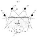
- FIG. 2is a plan view showing an example in which cameras 201 to 204 for measuring poses for teaching are arranged with respect to the workbench 10.
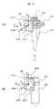
- FIG. (a)is a perspective view of a micropipette 310 attached with a marker plate 311 for measuring poses for teaching
- (b)is a perspective view of a test tube 320 attached with a marker plate 321 for measuring poses for teaching.
- Itis a diagram.
- (a)is a perspective view of a teaching glove 410 incorporating pressure-sensitive switches 411 to 416 for detecting the positioning, gripping, and function operation of a grasped object by the teacher 11;
- FIG. 11is a perspective view of a teaching glove 410 showing an example of wearing and gripping a micropipette 310.
- FIG. FIG. 3is a perspective view of a teacher 11 and its surroundings, showing an example using a footswitch 501 for inputting positioning, gripping, and functional operations of an object to be grasped by the teacher 11 and a microphone 502 for inputting the teacher's 11 voice;
- . 4is a flow chart showing a procedure of dispensing a reagent into a test tube 320 using a micropipette 310.
- FIG. 4is a front view of the workbench 10 on which a chip box 702 and reagent bottles 704 are placed; 4 is a flow chart showing a procedure of processing of a teaching program generation unit 106.
- FIG. FIG. 9is a flow chart showing the continuation of the processing procedure of the teaching program generation unit 106 shown in FIG. 8; FIG.
- FIG. 10is a table showing an example of data of a teaching pose partial sequence generated by the teaching program generating unit 106
- (b)is a table generated from the teaching pose partial sequence generated by the teaching program generating unit 106.
- 10is a table showing an example of data of a sequence of joint displacements of a robot to be processed
- 3is a diagram showing an example of a robot teaching program generated by a teaching program generation unit 106 expressed in the form of a sequential function chart
- FIG. FIG. 12is a diagram showing an example of editing the sequential function chart shown in FIG. 11 by the teaching program editing unit 107
- 13is a diagram showing an example in which the sequential function chart shown in FIG. 12 is further edited by the teaching program editing unit 107;
- FIGS. 11 to 13(a) is a diagram showing a command string 1401 described as an action of step s2 in the sequential function charts shown in FIGS. 11 to 13, and (b) is the sequential function charts shown in FIGS. (c) shows the contents of the transition conditional expression 1402 described as the processing of the transition t201 on the output side of the action in step s2 in FIG.
- a diagram showing the described command sequence 1403(d) shows the contents of the transition condition expression 1404 described as the processing of the transition t401 on the output side of the action in step s4 in the sequential function charts shown in FIGS.
- (e)shows the command sequence 1405 described as the processing of step s6 in the sequential function charts shown in FIGS.
- FIG. 11 to 13shows the sequential - It is a diagram showing the contents of the transition conditional expression 1406 described as the processing of the transition t601 on the output side of the action in step s6 in the function chart.
- (a)is a front view of a screen 1501 for editing the processing of step s4 of the sequential function chart shown in FIGS. 11 to 13 by operating the teaching program editing unit 107
- (b)is a teaching program editing
- FIG. 15is a front view of a screen 1503 for editing a transition conditional expression of transition t401 of the sequential function chart shown in FIGS. 11 to 13 by operating the unit 107
- 4is a flow chart showing the procedure of processing of a teaching program execution unit 108.
- a robot work teaching deviceis a robot teaching device that generates a teaching program that enables a robot to reproduce the motion of a grasped object by a teacher demonstrating a series of tasks.
- a robot teaching deviceBy measuring the position and orientation of the object to be grasped in time series, and detecting the positioning, gripping, function operation, and confirmation action of the object to be grasped in synchronization with the measurement, the time series of the object to be grasped at the timing of positioning
- the position and orientation of a grasped object grasped by a teacherare measured as teaching poses, and in synchronism with this, it is determined that the grasped object has been positioned.
- the teaching pose sequenceis divided and stored as a teaching pose partial sequence.
- it detects that the object to be grasped, the operation of the function of the object to be grasped, and the confirmation of the work stateare performed, and the object to be executed at the timing when these are detected.
- the action of grasping a grasped object, operating a function of a grasped object, and confirming the work stateis stored.
- portions of the teaching posesare adjusted so that the positions and postures of the grasped objects to be gripped by the robot are the same as those of the teaching poses included in the teaching pose partial sequences.
- the sequenceis converted into a robot joint displacement sequence, commands to be executed are generated, and executed according to the order taught by the instructor. is generated, and a teaching program for the robot is written so as to be executed at the timing when grasping of the grasped object, functional manipulation of the grasped object, and work state confirmation are detected.
- the robot teaching program generated herethe robot was made to perform a series of tasks in the same manner as the tasks demonstrated by the instructor.
- the position and orientation of a grasped object grasped by a teacherare measured as teaching poses, and the grasped object is positioned synchronously with this.
- the teaching pose sequenceis divided and stored as a teaching pose partial sequence.
- itdetects that the object to be grasped, the operation of the function of the object to be grasped, and the confirmation of the work state are performed, and the object to be executed at the timing when these are detected.
- the action of grasping a grasped object, operating a function of a grasped object, and confirming the work stateis stored.
- a partial sequence of teaching posesis adjusted so that the position and orientation of an object to be gripped by the robot are the same as those of each of the teaching poses included in the partial sequence of teaching poses. Converts to a sequence of robot joint displacements, generates commands to be executed, executes them according to the order instructed by the instructor, and generates commands for grasping the grasped object, operating the grasped object's functions, and checking the work state. Then, a teaching program for the robot is written so as to be executed at the timing when the action of grasping the object to be grasped, operating the function of the object to be grasped, and confirming the work state is detected. Furthermore, by executing the robot teaching program generated here, the robot is caused to perform a series of tasks in the same manner as the tasks demonstrated by the instructor.
- FIG. 1is a schematic diagram illustrating the overall configuration of a robot work teaching device 1 according to an embodiment of the present invention.
- the robot work teaching device 1includes cameras 201 to 204 for measuring the three-dimensional position and orientation of a grasped object grasped by a teacher 11, a right marker plate 311 attached to the grasped object, a left marker plate 321, and a teaching device. It comprises a computer 100 that executes various devices (to be described later) for detecting the positioning of a grasped object grasped by the person 11, grasping motions, function operations, and work state confirmation, and arithmetic processing units related to work instruction.
- the teacher 11works toward the workbench 10 in order to teach the robot 12.
- the teacher 11dispenses a reagent into a test tube 320, which is a working object, held with the left hand, using a micropipette 310, which is a working tool, held with the right hand.
- the object to be grasped by the teacher 11will be referred to as a first object to be grasped.
- a right marker plate 311 for motion captureis attached to the micropipette 310 .
- a left marker plate 321 for motion captureis attached to the test tube 320 .
- each of the right marker plate 311 and the left marker plate 321is attached with a reflective marker for motion capture in a unique arrangement.
- the marker plate 311 and the left marker plate 321are recognized separately, and the position and orientation of the marker coordinate system set at the center of each plate are measured.
- the micropipette 310 and the test tube 320are examples of objects to be grasped by the teacher 11, and the objects to be grasped are not limited to these.
- the robot 12is installed facing a workbench 10' similar to workbench 10, and is instructed to dispense reagents into test tubes 320' held by its left hand with a micropipette 310' held by its right hand. be.
- the object to be grasped by these robots 12will be referred to as a second object to be grasped.
- a micropipette 310 ′ and a test tube 320 ′correspond to the micropipette 310 and the test tube 320 (first grasped object) grasped by the teacher 11 .
- Micropipette 310' and test tube 320'can be of the same shape as micropipette 310 and test tube 320, but need not be exactly the same, and can be of the same type as long as differences in shape are recognized. and may differ in shape, material, and other properties.
- the robot 12is a dual-armed robot having a left arm 121 and a right arm 122, but is not limited to this.
- the robotmay be a combination of two robots, a single-arm robot with a right arm and a single-arm robot with a left arm.
- the two robotsmay be different types of robots. It is also possible to reproduce the work of the teacher with two arms by a robot having three or more arms.
- the robot 12is not limited to a model simulating a human body as shown in the drawing, and is not limited to a specific shape as long as it can perform the desired motion.
- the teaching pose measurement unit 101measures the three-dimensional position and orientation of the object (micropipette 310, test tube 320) gripped by the instructor 11 from the images acquired by the cameras 201-204. Specifically, the teaching pose measurement unit 101 images the right marker plate 311 and the left marker plate 321 with the cameras 201, 202, 203, and 204, and calculates the three-dimensional positions of the right marker plate 311 and the left marker plate 321, respectively. and attitude in chronological order.
- the three-dimensional position and orientation of an objectwill be referred to as "pose”.
- the "pose"is data including not only the position of the object to be grasped, but also its tilt and rotation.
- the positioning detection unit 102detects the position of the object to be grasped in synchronization with the measurement of the pose of the object to be grasped (hereinafter referred to as the teaching pose) by the teaching pose measurement unit 101 during the teaching operation by the teacher 11. detect that Specifically, the positioning of the object to be grasped is detected when the pose of the object to be grasped measured by the teaching pose measuring unit 101 does not change for a certain period of time, or a pressure-sensitive switch attached to the finger of the teacher 11, which will be described later, is attached to the finger. 413 to 416 (see FIG. 4), a foot switch 501 (see FIG. 5) operated by the teacher 11 at his/her feet, or a microphone 502 (see FIG. 5) for inputting the voice of the teacher 11. is positioned.
- the gripping motion detection unit 103detects the gripping motion of the object to be gripped in synchronization with the measurement of the teaching pose by the teaching pose measuring unit 101 during the teaching work by the teacher 11 . Specifically, pressure-sensitive switches 413 to 416 (see FIG. 4) worn on fingers by the teacher 11, which will be described later, a foot switch 501 (see FIG. 5) operated by the teacher 11, or the voice of the teacher 11 is received from any one of the microphones 502 (see FIG. 5) for inputting , and the gripping operation (gripping/releasing) of the gripped object is detected.
- the functional operation detection unit 104detects that the function of the object to be grasped has been operated in synchronization with the measurement of the teaching pose during the teaching work by the teacher 11 . Specifically, pressure-sensitive switches 411 and 412 (see FIG. 4) worn on fingers by the teacher 11, which will be described later, a foot switch 501 (see FIG. 5) operated by the teacher 11, or the voice of the teacher 11 received a signal from one of the microphones 502 (see FIG. 5) for inputting , and an operation of a function possessed by the object to be grasped (for example, pressing the suction/discharge button 313 of the micropipette 310, etc.) was performed. to detect
- the work state confirmation motion detection unit 105detects that the work state has been confirmed during the teaching work by the teacher 11 in synchronization with the measurement of the teaching pose. Specifically, pressure-sensitive switches 413 to 416 (see FIG. 4) worn on fingers by the teacher 11, which will be described later, a foot switch 501 (see FIG. 5) operated by the teacher 11, or the voice of the teacher 11 receives a signal from any of the microphones 502 (see FIG. 5) that inputs the , and detects that the work state has been confirmed (for example, the work state has been confirmed by the camera image recognition function provided in the robot 12). .
- the teaching program generation unit 106generates time-series data of teaching poses at the timing when it is detected that the object to be grasped by the teacher 11 (first object to be grasped) is positioned during the teaching work by the teacher 11. (sequence) is divided and stored as a subsequence of teaching poses. Also, at the timing when the grasping action of the first grasped object and the functional operation of the first grasped object are detected, these are stored as the actions for the first grasped object, and at the timing when the work state confirmation is detected, the operation is performed. It is stored as a state confirmation operation.
- the teaching posesare set so that the pose of the object to be gripped (the second object to be gripped) to be gripped by the robot 12 is the same pose as each of the teaching poses included in the partial sequence of the teaching poses. is converted into a sequence of joint displacements of the robot 12, commands to be executed are generated, and executed according to the order taught by the teacher 11. is executed at the timing when the motion to the first grasped object is detected, and a command for confirming the work state is generated and executed at the timing when the work state confirmation is detected. Generate a program.
- the teaching program editing unit 107allows the teacher 11 to edit the teaching program for the robot 12 generated by the teaching program generating unit 106, such as corrections and additions, through a graphical user interface, which will be described later. It is a tool to
- the teaching program executing unit 108sequentially interprets the commands described in the teaching program for the robot 12 generated by the teaching program generating unit 106 or the teaching program for the robot 12 edited by the teaching program editing unit 107, It outputs a joint drive command for executing an action, a drive command for a hand provided at the tip of the robot 12, and the like, and controls each joint axis of the robot 12, the hand, and the like.
- FIG. 2shows an example of the layout of the cameras 201 to 204 connected to the teaching pose measuring unit 101 shown in FIG.
- Cameras 201 to 204are mounted on the work table in order to measure the pose of the object to be grasped (such as the micropipette 310 and the test tube 320 shown in FIG. 1) held by the teacher 11 who works toward the work table 10. It is arranged on the opposite side of the teacher 11 with 10 interposed therebetween.
- the fields of view 210 of the cameras 201 to 204are set so as to overlap each other on the workbench 10, so that the work area on the workbench 10 is entirely covered, and the poses of work tools and work objects as objects to be grasped are determined. is imaged.
- a workbench coordinate system 2100( ⁇ W in the drawing) is set on the workbench 10 as a reference coordinate system for motion capture, and poses of objects to be grasped (work tools, work objects) measured by motion capture are set. is expressed as a pose in the workbench coordinate system 2100 .
- FIG. 3(a)shows the state where the right marker plate 311 is attached to the micropipette 310
- FIG. 3(b)shows the state where the left marker plate 321 is attached to the test tube 320.
- FIG. The micropipette 310has an aspirate/dispense button 313 .
- the micropipette 310is equipped with an attachment 312 for attaching a right marker plate 311 .
- an attachment 322 for attaching a left marker plate 321is attached to the test tube 320, as shown in FIG. 3(b).
- the right marker plate 311has one axis (for example, the X axis) of the right marker plate coordinate system 3100 ( ⁇ RM in the drawing) set in the right marker plate 311 with respect to the micropipette 310 . It is attached so as to be substantially aligned with the vertical direction.
- the left marker plate 321has one axis (for example, X It is attached so as to substantially match the vertical direction of 320 .
- a right marker plate coordinate system 3100is defined as a coordinate system whose origin is the center of the right marker plate 311 when registering the arrangement pattern of the reflective markers 311a to 311d.
- the reflective markers 321a to 321d shown in FIG. 3(b)are arranged asymmetrically in the horizontal and vertical directions on the substrate of the left marker plate 321.
- the teaching pose measurement unit 101can easily adjust the right marker plate 311 and the left marker plate 321 based on the arrangement patterns. can be identified.
- the size and color of the reflective markers 311a to 311d in FIG. 3(a)are different from those of the reflective markers 321a to 321d in FIG. is also possible. It is also possible to change the number of reflective markers on the marker plate 311 in FIG. 3A and the marker plate 321 in FIG.
- FIG. 4shows a teaching glove 410 containing pressure-sensitive switches 411 to 416 used as detection devices for the detection units 102 to 105 shown in FIG. It is a figure which shows the example holding
- FIG. 4(a)shows an example of arrangement of the pressure-sensitive switches 411 to 416 in the glove for teaching 410, and FIG. - Shows a state in which the discharge button 313 is pressed.
- the pressure-sensitive switches 411 and 412are arranged on the thumb portion of the teacher 11 and can detect pressing of the suction/discharge button 313 of the micropipette 310 . Also, the pressure-sensitive switches 413 to 416 can detect that the instructor 11 has gripped the micropipette 310 .
- the signals from the pressure-sensitive switches 411 to 416are input to the signal processing unit 417 (signal 4120), and the results of noise filtering and threshold determination processing are output to the computer 100 (signal 4170).
- FIG. 5is a diagram showing an example using a footswitch 501 used as a detection device for each of the detection units 102 to 105 shown in FIG.
- a plurality of foot switches 501are provided. For example, at the timing when the instructor 11 grips the micropipette 310 or operates the suction/discharge button 313 during operation teaching, the foot switches 501 assigned to these gripping operations and functional operations are switched. By pressing the switch 501, it is detected that these grasping motions and functional operations have been performed.
- the microphone 502can pick up the voice of the instructor 11 during the operation instruction. By inputting the voice assigned to these gripping motions and functional operations, it is detected that these gripping motions and functional operations have been performed.
- the teaching glove 410 shown in FIG. 4 and the foot switch 501 and the microphone 502 shown in FIG. 5can be used as detection devices connected to the detection units 102 to 105 shown in FIG. It is also possible to use these devices in combination according to the content of work teaching, work environment, and the like.
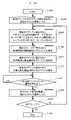
- FIG. 6is a flow chart showing the procedure of dispensing the reagent into the test tube 320 using the micropipette 310 .
- the teacher 11starts work (S601)
- the left handmoves to the gripping position of the test tube 320 placed on the test tube stand (S602), and grips the test tube 320 (S603).
- the test tube 320is normally gripped (S604).
- the right handis moved to the gripping position of the micropipette 310 placed on the pipette stand (S605), and the micropipette 310 is gripped (S606).
- the micropipette 310is normally gripped (S607).
- the left-hand test tube 320is moved to the standby position (S608).
- the micropipette 310 on the right handis moved to the tip attachment position, and the tip is attached (S609). Here, it is confirmed visually that the chip is normally attached (S610).
- the micropipette 310is moved to the reagent aspiration position within the reagent bottle (S611), and the aspiration/discharge button 313 of the micropipette 310 is pressed to aspirate the reagent into the chip (S612).
- the reagenthas been normally sucked into the chip (S613).
- the tip end of the micropipette 310is moved to the discharge position in the test tube 320 (S614), and the suction/discharge button 313 of the micropipette 310 is pressed to discharge the reagent in the tip into the test tube 320 (S615). .
- the suction/discharge button 313 of the micropipette 310is pressed to discharge the reagent in the tip into the test tube 320 (S615).
- the reagenthas been discharged normally into the test tube 320 (S616). It should be noted that in FIG. 6, the procedure of the subsequent work is omitted.
- the above procedureshows the work procedure by the teacher 11, but the robot 12 also follows exactly the same procedure using the micropipette 310' and the test tube 320'.
- the work stateis confirmed by the image recognition function of the camera connected to the robot 12 . It should be noted that it is also possible to confirm such a working state by means other than the image recognition of the camera. It is also possible to check the holding state of the test tube 320'. It is also possible to check the state of reagent suction and discharge by detecting the liquid level using a photoelectric sensor.
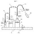
- FIG. 7shows the movement path of the micropipette 310 held by the right hand when the instructor 11 performs the dispensing operation using the micropipette 310 on the workbench 10, and divides this as a partial sequence of poses for teaching.
- FIG. 11is a diagram schematically showing an example of doing.
- the right handis moved to the gripping position (represented as P1 in the figure) of the micropipette 310 placed on the pipette stand 701, and the micropipette 310 is gripped here (represented as Grasp in the figure).
- the micropipette 310is normally gripped (indicated as Check 1 in the figure).
- the gripping operation of the micropipette 310is performed by pressing any of the pressure-sensitive switches 413 to 416 of the teaching glove 410 shown in FIG. 4, or by pressing the foot switch 501 shown in FIG. Alternatively, it is detected by voice input through the microphone 502 (for example, utterance of "Grasp").
- the grasping state of the micropipette 310can also be confirmed by pressing any of the pressure-sensitive switches 413 to 416 of the teaching glove 410, pressing the foot switch 501, or sounding the microphone 502. Detected by input (e.g., saying "Check grasp pipet").
- a movement path 710is composed of a sequence of points P1, P2, . . . These point sequences are teaching poses obtained by measuring the movement of the micropipette 310 held by the teacher 11 in the three-dimensional space by motion capture when the teacher 11 demonstrates the work. Time-series data measured at sampling intervals. The data of the sequence of points forming the movement path 710 is the partial sequence of the teaching pose.
- Positioning at the positioning point Piis detected by stopping the operation for a certain period of time at Pi, or by pressurizing one of the pressure-sensitive switches 413 to 416 of the teaching glove 410, or by the foot switch. It is detected by pressing 501 or voice input by microphone 502 (for example, saying "Stop here").
- the confirmation operation of the attached state of the tip 703 of the micropipette 310is performed by pressurizing any of the pressure-sensitive switches 413 to 416 of the teaching glove 410, by pressing the foot switch 501, or by the microphone 502. Detected by voice input (for example, saying "Check set tip").
- the micropipette 310 with the chip 703 attachedis moved along the movement path 711 to the reagent aspirating position (Pj in the figure) in the reagent bottle 704 and positioned.
- the aspirate/discharge button 313 of the micropipette 310is pressed to aspirate the reagent 705 into the tip 703 (Aspirate in the drawing). Furthermore, it is confirmed that the reagent 705 is normally sucked into the chip 703 (Check 3 in the figure).
- the movement path 711is composed of a sequence of points from the movement start point Pi to the positioning point Pj, Pi, Pi+1, . Alternatively, it is detected by pressurization of any of the pressure-sensitive switches 413 to 416 of the teaching glove 410 , pressing of the foot switch 501 , or voice input by the microphone 502 .
- Pressing the suction/discharge button 313 of the micropipette 310 at the positioning point Pj, that is, the functional operation of the micropipette 310is performed by pressing one of the pressure-sensitive switches 411 and 412 of the teaching glove 410. It is detected by pressing the foot switch 501 or voice input by the microphone 502 (for example, uttering "Aspirate").
- confirming that the reagent 705 has been normally sucked into the chip 703is similarly done by pressing any of the pressure-sensitive switches 413 to 416 of the teaching glove 410 and pressing the foot switch 501. or by detecting voice input (for example, utterance of "Check aspirate") by the microphone 502.
- the micropipette 310 sucking the reagent 705is moved along the movement path 712 to the reagent discharge position (Pk in the figure) in the test tube 320 and positioned (the test tube 320 is held in the left hand in advance). (assuming that it is waiting for Here, the suction/discharge button 313 of the micropipette 310 is pressed to discharge the reagent 705 into the test tube 320 (Dispense in the drawing). Furthermore, it is confirmed that the reagent 705 has been discharged normally into the test tube 320 (Check 4 in the figure).
- the movement path 712is composed of a sequence of points Pj, Pj+1, . . . Pk from the movement start point Pj to the positioning point Pk. Alternatively, it is detected by pressurization of any of the pressure-sensitive switches 413 to 416 of the teaching glove 410 , pressing of the foot switch 501 , or voice input by the microphone 502 .
- the suction/discharge button 313 of the micropipette 310is pressed at the positioning point Pk, that is, the functional operation of the micropipette 310 is the pressing of one of the pressure-sensitive switches 411 and 412 of the teaching glove 410. It is detected by pressing the footswitch 501 or voice input by the microphone 502 (for example, uttering "Dispense").
- the operation for confirming the discharge state into the test tube 320is also performed by pressing any of the pressure-sensitive switches 413 to 416 of the teaching glove 410, pressing the foot switch 501, or pressing the microphone 502. Detected by voice input by (for example, saying "Check dispense").
- FIGS. 8 and 9are flowcharts showing the procedure of processing of the teaching program generation unit 106.
- FIG.In the teaching program generation unit 106, when the teacher 11 starts teaching the work by demonstrating the work (S801), the teaching pose measuring unit 101 measures the pose of the object to be grasped by the teacher 11 as the teaching pose. (S802).
- each pose of the object to be grasped grasped by the right hand and left hand of the teacher 11is measured as a teaching pose.
- the object to be grasped positioning detection unit 102detects the positioning of either the right hand or the left hand to be grasped (if YES in S803), the teaching of the hand whose positioning has been detected until now is detected.
- the time-series data (sequence) of the hand poseis divided and stored as a partial sequence of the teaching pose of the hand whose positioning has been detected (S804). If the positioning of either the right hand or the left hand to be grasped has not been detected (NO in S803), the teaching pose measurement is continued (S802).
- the partial sequence of teaching posesis converted into a joint displacement sequence of the robot 12 so that the pose of the object to be grasped by the robot 12 becomes the same as the teaching pose, and executed.
- a commandis generated (S805).
- the gripping motion detecting unit 103detects a gripping motion of the object to be gripped by the hand on which the positioning is detected (YES in S806), this is treated as a gripping motion of the object to be gripped in the partial sequence of the pose for teaching.
- S807On the other hand, when no grasping motion is detected (NO in S806), the process proceeds to S809.
- a command for performing a gripping motion for the gripped objectis generated (S808). Further, when the functional operation detection unit 104 detects a functional operation of the grasped object by the hand that detected the positioning (if YES in S809), this is treated as a functional operation of the grasped object in the teaching pose partial sequence. Store (S810). On the other hand, when the functional operation of the grasped part is not detected (NO in S809), the process proceeds to S812 shown in FIG.
- a command for performing a functional operation of the object to be graspedis generated (S811). Further, when the work state confirmation movement detection unit 105 detects a work state confirmation movement by the hand that detected the positioning (if YES in S812), this is used as the work state confirmation movement in the teaching pose partial sequence. Store (S813). On the other hand, when no confirmation action is detected (NO in S812), the process proceeds to S815.
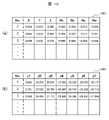
- FIG. 10is a diagram showing an example of the teaching pose partial sequence generated by the teaching program generation unit 106 and the robot joint displacement sequence data generated from this.
- FIG. 10Ashows an example of teaching pose partial sequence data 1001, where the pose of a grasped object grasped by the teacher 11 is expressed as a sequence of three-dimensional positions and orientations (quaternions). is doing.
- FIG. 10(b)shows an example of joint displacement sequence data 1002 of the robot 12, which is represented here as a sequence of joint angles when the arm of the robot 12 has a 7-axis configuration.
- the teaching pose partial sequence data 1001 and the joint displacement sequence data 1002 of the robot 12are managed as data for one hand of the teacher 11 and the robot 12, respectively. is a two-handed operation, these data are generated for the right hand and the left hand.
- the partial sequence data 1001 of teaching poses and the sequence data 1002 of joint displacements of the robot 12are stored as time-series data, and three-dimensional position and posture data and joint angle data at each time are arranged in chronological order. data. These data are given serial numbers (indicated by No. in the figure), and each serial number corresponds to each time.
- each timeindicates the time updated in the sampling period of the motion capture described above, and for example, the time is incremented by 50 milliseconds.
- the position of the teaching poseis represented by a Cartesian coordinate system (X, Y, Z), but it is also possible to represent this by another coordinate system, such as a cylindrical coordinate system.
- the postures of teaching posesare represented by quaternions (Rx, Ry, Rz, Rw), they can also be represented by roll, pitch, yaw, Euler angles, and the like.
- FIG. 10(b)shows an example in which the arm of the robot 12 has a seven-axis configuration (the names of the axes are J1 to J7), but other axis configurations may be used.
- the joint displacements of J1 to J7are represented by angle data of the rotation axis, it is also possible to represent joint displacements other than this, such as the position of the translational axis.
- FIG. 11is a diagram showing an example of a robot teaching program generated by the teaching program generation unit 106 expressed in the form of a sequential function chart.
- an initial step s1is generated, and the step name "Initial" is described here.
- a transition t101 on the output side of the initial step s1is generated at the same time, and a comment "Ready” is described here.
- a linkis generated connecting the initial step s1 and the transition t101. It should be noted that there is no transition condition between the action executed in the initial step s1 and the transition t101 on the output side, and when program execution is started, the next step is unconditionally shifted.
- the initial step s1is internally given the step number 1, and the transition t101 is given the transition number 101 (indicating the first transition on the output side of step s1). Assignment of step numbers and transition numbers is the same for subsequent steps and transitions.
- step s2As described in the processing procedure of FIG. 8, when the positioning of any hand of the teacher 11 is detected, the next step s2 is generated and the step name "Step 2" is described here. At the same time, a transition t201 on the output side of step s2 is generated, and a comment "Succeeded" is written here. Furthermore, a link is generated between step s2 and transition t201. Note that the step name and comment automatically described here can be corrected later by the teaching program editing unit 107 .
- step s2when step s2 is generated, as an action to be executed there, first, a partial sequence of teaching poses (corresponding to FIG. 10(a)) of the hand whose positioning has been detected is generated. A sequence of joint displacements of the robot 12 (corresponding to FIG. 10B) is generated so that the pose of the object to be grasped by is the same as the teaching pose, and a command for execution is generated. At this time, if a gripping motion of the hand whose positioning has been detected is detected, a command for performing a gripping motion of the gripped object is generated. Further, when the operation of confirming the working state of the hand that detected the positioning is detected, a command for confirming the working state is generated.
- transition condition for transition t201a conditional expression for judging the success or failure of the confirmation result is described when the confirmation operation of the work state is performed. If the operation to confirm the work state is not performed, it means that the joint displacement sequence of the robot, that is, the operation up to the positioning of the robot has been completed normally. is normally completed as the transition condition of transition t201.
- FIG. 12shows an example of the sequential function chart shown in FIG. 11 edited by the teaching program editing unit 107.
- the step namesare corrected to names representing the work content (an example of English notation is shown).
- steps corresponding to the steps shown in FIG. 11are indicated by the same numbers and marked with * .
- the work contents of the same step numbers in FIGS. 11 and 12are the same. That is, FIG. 12 becomes a program representing the following work.
- test tube 320'is gripped by the hand of the left arm 121, and the micropipette 310' is gripped by the hand of the right arm 122, and taken out from the respective stands (s2 * ).
- test tube 320' gripped by the left arm 121is moved to the standby position (s3 * ).
- tip 703 in the tip box 702is attached to the micropipette 310' gripped by the hand of the right arm 122 (s4 * ).
- the reagent 705 in the reagent bottle 704is aspirated into the tip 703 of the micropipette 310' (s5 * ), and is inserted to the discharge position in the test tube 320' gripped by the hand of the left arm 121 (s6 * ), and the reagent 705 is discharged (s7 * ).
- the micropipette 310'is withdrawn from the test tube 320' (s8 * ) and the tip 703 is removed from the micropipette 310' (s9 * ).
- the test tube 320' gripped by the hand of the left arm 121is shaken to stir the reagent 705 therein (s10 * ).
- the test tube 320' and the micropipette 310'are placed on their respective stands (s11 * ), completing the series of operations (s12 * ).
- FIG. 13is a diagram showing an example in which the sequential function chart shown in FIG. 12 is further edited.
- the tip 703is attached to the micropipette 310' (s4 * )
- the attached state of the tip 703is confirmed by image recognition of the camera, and if the attachment of the tip 703 is successful (t401), the next step s4 is performed.
- *shows an example in which an error handling process is added such that if the mounting of the chip 703 fails (t402), the mounting operation of the chip 703 is performed again (s13 * ).
- a transition conditionfor example, a conditional expression for determining the type of reagent 705
- an actionfor example, a command for executing an operation that increases the number of times the test tube 320′ is shaken
- FIG. 14is a diagram showing an example of processing descriptions of steps and transitions in the sequential function charts shown in FIGS.
- FIG. 14(a)shows a command string 1401 described as an action of step s2 in FIGS. 11-13.
- "larm_move (“traj_larm_s2")" in the command string 1401is a partial sequence of teaching poses of the left arm 121 of the robot 12 divided as the motion of step s2 (s2 * ) (automatically stored under the name "traj_larm_s2"). is executed).
- rarm_move("traj_rarm_s2"is a command to execute a partial sequence of teaching poses for the right arm 122 of the robot 12 (automatically stored under the name “traj_rarm_s2").
- “larm_grasp( )”is a command for closing the hand of the left arm 121 of the robot 12 to grasp an object (test tube 320' in this case).
- “rarm_grasp( )”is a command to close the hand of the right arm 122 of the robot 12 to grasp an object (micropipette 310' in this case).
- “larm_check("get_tube”)”is a command for confirming by image recognition whether the hand of the left arm 121 is properly gripping the test tube 320'.
- “rarm_check("get_pipet”)”is a command for confirming by image recognition whether the hand of the right arm 122 is holding the micropipette 310' normally.
- FIG. 14(b)shows a transition conditional expression 1402 described as processing of transition t201 on the output side of step s2 (s2 * ).
- 12is a conditional expression for judging the success or failure of the confirmation result of the work state. Note that these conditional expressions are automatically generated from the contents of the command string 1401 .
- FIG. 14(c)is a command sequence 1403 described as the processing of step s4 (s4 * ) in FIGS. 1404 is shown. These processing contents are the same as those of the command string 1401 and the transition conditional expression 1402, and "rarm_check("set_tip")" correctly attaches the tip 703 to the micropipette 310' gripped by the hand of the right arm 122. This command is used to check whether the
- FIG. 14(e)is a command sequence 1405 described as the processing of step s6 (s6 * ) in FIGS. 1406 is shown.
- "rarm_move("traj_rarm_s6")" in the command string 1405is a teaching pose partial sequence of the right arm 122 of the robot 12 divided as the motion of step s5 (s5 * ) (automatically stored under the name “traj_rarm_s6"). is executed).
- FIG. 15A and 15Bare diagrams showing an example of display and input of a screen that constitutes the teaching program editing unit 107.
- FIG. A screen constituting the teaching program editing unit 107may be provided in the computer 100 or may be provided in a place away from the computer 100 (not shown).
- FIG. 15(a)shows a screen 1501 for editing the processing of step s4 (s4 * ) of the sequential function charts shown in FIGS.
- a step edit window 1502is displayed, where the name 1502a of step s4 is edited (rewrite "Step 4" to "Set tip” in the example of the figure). ) and edit the command string 1502b to be executed in this step s4 * .
- FIG. 15(b)shows a screen 1503 for editing the transition conditional expression of transition t401.
- a transition edit window 1504is displayed, where the comment 1504a of the transition t401 is edited and the conditional expression 1504b of the transition condition to be determined by this transition t401 is edited. (in this example, the automatically generated description is adopted as is).
- FIG. 16is a flow chart showing the processing procedure of the teaching program execution unit 108.
- FIG.When the teaching program execution unit 108 starts executing the teaching program (S1601), first, the step number of the step following the initial step is set to the sequential function chart, which is the teaching program as shown in FIGS. It is obtained from the connection relation of the link and substituted for the internally held current step number (S1602). Next, various commands described in the step indicated by the current step number are executed. That is, a command is executed to generate and execute a joint displacement sequence of the robot 12 so that the pose of the object to be grasped by the hand of the robot 12 becomes the same as the teaching pose (S1603).
- a command for gripping an object to be gripped by the hands of the robot 12is executed (S1604), and a command for functionally manipulating the object to be gripped by the hands of the robot 12 is executed (S1605). Further, a command for confirming the working state of the robot 12 is executed (S1606).
- the conditional expression described as the transition conditionis established at any transition on the output side of the current step (if YES in S1607), the next transition is made from the link connection relation of the sequential function chart. A step number is obtained and substituted for the current step number (S1608). Also, if the transition condition is not satisfied at any transition on the output side of the current step (NO in S1607), it waits until one of these is satisfied.
- the robotwhen converting human work into robot work, the robot can perform a series of tasks simply by demonstrating the work as usual using a grasped object used in the work. It is possible to generate the teaching program for executing the work of , including not only the description of the movement path of the robot, but also the grasp of the grasped object to be grasped by the robot, the functional operation of the grasped object, and the work state confirmation. In comparison with the conventional method of separately programming operation contents and operation state confirmation processing after measuring the motion of the object to be grasped, it becomes easier to teach the robot work, and the development efficiency of the teaching program can be improved.
- the present inventionis not limited to the above-described embodiments, and includes various modifications.
- the above-described embodimentshave been described in detail in order to explain the present invention in an easy-to-understand manner, and are not necessarily limited to those having all the configurations described.
- part of the configuration of one embodimentcan be replaced with the configuration of another embodiment, and the configuration of another embodiment can be added to the configuration of one embodiment.
- SYMBOLS 1Robot work teaching device, 100... Computer, 10, 10'... Workbench, 11... Instructor, 12... Robot, 201 to 204... Camera, 310, 310'... Micropipette, 320, 320'... Test tube , 311, 321... marker plate, 210... field of view of camera, 2100... workbench coordinate system, 311a to 311d, 321a to 321d... reflective marker, 312, 322... attachment, 3100, 3200... marker plate coordinate system, 410...
Landscapes
- Engineering & Computer Science (AREA)
- Robotics (AREA)
- Mechanical Engineering (AREA)
- Physics & Mathematics (AREA)
- General Physics & Mathematics (AREA)
- Automation & Control Theory (AREA)
- Manipulator (AREA)
Abstract
Description
Translated fromJapanese本発明は、人の作業動作をロボットに教示するためのロボットの作業教示装置及び作業教示方法に関する。The present invention relates to a robot work teaching device and a work teaching method for teaching human work motions to a robot.
特許文献1のロボット教示システムは、ロボットの教示位置を指定するためのボタンを備えた教示ツールを教示者がロボットを動作させたい位置に合わせ、ここでボタンを押すことで教示位置を指定し、このときの教示ツールの位置及び姿勢をステレオカメラで計測して、これをロボットの教示位置として決定し、さらに、ここで決定した教示位置の間を補間してロボットを動作させる教示プログラムを生成するように構成されている。In the robot teaching system of
また、特許文献2には、画像情報を含む作業情報を取得する取得装置を備えたロボット教示システムが記載されている。In addition,
ロボットの手首部に備えられたハンドにより、様々な作業対象物や作業用ツールを把持し、さらに作業用ツールが有する各種機能を操作しながら、一連の作業をロボットにより実行させる場合、このような作業対象物や作業用ツールの把持や操作に関するコマンドをロボットの教示位置のシーケンス(ロボットの移動経路)に関連付けながら、ロボットの教示プログラムの中に記述する必要がある。When the robot is caused to perform a series of operations while grasping various work objects and work tools with a hand provided on the wrist of the robot and operating various functions of the work tools, such a It is necessary to describe in the teaching program of the robot while associating the commands for gripping and manipulating the work object and work tool with the sequence of teaching positions of the robot (moving path of the robot).
また、ロボットの一連の作業の各工程の区切りにおいて、現在の工程が正常終了したかどうかを判断し、次の工程に移行する処理もロボットの教示プログラムの中に記述すべき内容である。例えば、工程の最後に作業対象物の状態を画像認識し、事前に記憶していた目標状態と同じになっていれば正常終了、そうでなければ異常終了と判定する処理が教示プログラムの中に記述される。In addition, at the delimitation of each process in a series of robot work, the process of determining whether the current process has ended normally and moving to the next process should also be described in the robot's teaching program. For example, at the end of the process, the image recognition of the state of the work object is performed, and if it is the same as the target state stored in advance, the processing is judged to be normal termination, otherwise the processing is determined to be abnormal termination. Described.
以上のようなロボットの教示プログラムの記述は、特許文献1で述べられたロボットの動作位置の教示とは別に、教示者が一つ一つ入力する必要があり、ロボットに実行させる作業内容が複雑になると、このような教示者による入力作業及びデバッグ作業が増加し、教示プログラムの開発工数が増大する原因となっていた。The description of the teaching program for the robot as described above needs to be input one by one by the instructor separately from the teaching of the operating position of the robot described in
また、特許文献2に開示されたロボット教示システムにおいても、ロボットによる被把持物への操作や作業状態の検出を教示することを、ロボットの動作位置の教示とは別に、教示者が一つ一つ入力する必要があり、教示者による入力作業及びデバッグ作業が増加し、教示プログラムの開発工数が増大する原因となっていた。Further, in the robot teaching system disclosed in
本発明は、上述のような課題を解決するためになされたもので、教示者が一連の作業を実演する際の作業対象物や作業用ツールなどの被把持物の動作を計測するとともに、この計測と同期して、教示者が被把持物の把持や操作、作業状態確認を行ったことを検出することで、ロボットに一連の作業を実行させるための教示プログラムを生成するロボットの作業教示装置及び作業教示方法を提供することを目的とする。SUMMARY OF THE INVENTION The present invention has been made to solve the above-described problems. A robot work teaching device that generates a teaching program for causing a robot to perform a series of tasks by detecting that the teacher has grasped or manipulated an object to be grasped and confirmed the work status in synchronization with measurement. And to provide a work teaching method.
上記した課題を解決するために、本発明では、教示者による作業をロボットに教示するロボットの作業教示装置を、教示者により把持される物体(作業対象物や作業用ツールなど)の位置及び姿勢である教示用ポーズを計測する教示用ポーズ計測部と、教示者により移動される物体が位置決めされたことを検出する位置決め検出部と、教示者により物体が把持されたことを検出する把持動作検出部と、教示者により物体が有する機能が操作されたことを検出する機能操作検出部と、教示者による物体への作業状態の確認が行われたことを検出する作業状態確認動作検出部と、教示用ポーズ計測部と位置決め検出部と把持動作検出部と機能操作検出部と作業状態確認動作検出部とからの信号を受けて教示者の動作ごとに分割したロボットの教示プログラムを生成する教示プログラム生成部と、この教示プログラム生成部で生成した教示プログラムを実行する教示プログラム実行部とを備えて構成した。In order to solve the above-described problems, the present invention provides a work teaching device for a robot that teaches a robot a work to be done by a teacher. a teaching pose measuring unit for measuring a teaching pose, a positioning detection unit for detecting that an object to be moved by the teacher has been positioned, and a gripping motion detection unit for detecting that the object has been gripped by the teacher. a function operation detection unit that detects that the teacher has operated a function of the object; a work state confirmation operation detection unit that detects that the teacher has confirmed the work state of the object; A teaching program that receives signals from a teaching pose measuring section, a positioning detection section, a grasping motion detection section, a functional operation detection section, and a work state confirmation motion detection section and generates a robot teaching program that is divided for each teacher's motion. It comprises a generation section and a teaching program execution section for executing the teaching program generated by the teaching program generation section.
また、上記した課題を解決するために、本発明では、教示者による作業をロボットに教示するロボットの作業教示方法を、教示者により把持される物体の位置及び姿勢である教示用ポーズを教示用ポーズ計測部で計測し、教示用ポーズの計測と同期して教示者により移動される物体が位置決めされたことを位置決め検出部で検出し、教示用ポーズの計測と同期して教示者により物体が把持されたことを把持動作検出部で検出し、教示用ポーズの計測と同期して教示者により物体が有する機能を操作することが行われたことを機能操作検出部で検出し、教示用ポーズの計測と同期して教示者による物体への作業状態の確認が行われたことを作業状態確認動作検出部で検出し、教示用ポーズ計測部と位置決め検出部と把持動作検出部と機能操作検出部と作業状態確認動作検出部とからの信号を受けて教示プログラム生成部で教示者の動作ごとに分割したロボットの教示プログラムを生成し、教示プログラム生成部で生成した教示プログラムを教示プログラム実行部で実行するようにした。Further, in order to solve the above-described problems, the present invention provides a method for teaching a work of a robot for teaching a work by a teacher to a robot. Measured by the pose measurement unit, the object moved by the teacher in synchronization with the measurement of the pose for teaching is detected by the positioning detection unit, and the object is moved by the teacher in synchronization with the measurement of the pose for teaching. The grasping motion detection unit detects that the object has been grasped, and the function operation detection unit detects that the teacher has operated a function of the object in synchronization with the measurement of the teaching pose, and detects the teaching pose. In synchronism with the measurement, the work state confirmation motion detection unit detects that the teacher has confirmed the work state of the object, and the pose measurement unit for teaching, the positioning detection unit, the gripping motion detection unit, and the function operation detection. The teaching program generation section receives signals from the unit and the work state confirmation motion detection section, generates a robot teaching program divided for each teacher's motion, and transmits the teaching program generated by the teaching program generation section to the teaching program execution section. I tried to run it with
本発明よれば、人の作業をロボットの作業に変換する際、人が作業で用いる作業対象物または作業用ツールなどの被把持物を用いて通常通りに作業を実演するだけで、ロボットに一連の作業を実行させるための教示プログラムを、ロボットの移動経路の記述だけでなく、ロボットにより把持される被把持物の把持、被把持物の機能操作、作業状態確認の記述も含めて生成できるため、ロボットの作業教示が容易になり、教示プログラムの開発効率を向上させるという効果がある。According to the present invention, when converting human work into robot work, the robot can perform a series of tasks simply by demonstrating the work as usual using a work object or a grasped object such as a work tool used in the work. It is possible to generate the teaching program for executing the work of , including not only the description of the movement path of the robot, but also the grasp of the grasped object to be grasped by the robot, the functional operation of the grasped object, and the work state confirmation. , the work teaching of the robot is facilitated, and there is an effect that the development efficiency of the teaching program is improved.
本発明の実施形態に係るロボットの作業教示装置は、教示者が一連の作業を実演することで被把持物の動作をロボットで再生できる教示プログラムを生成するロボット教示装置であって、カメラやセンサなどで被把持物の位置及び姿勢を時系列に計測し、それと同期して被把持物に対する位置決め、把持、機能操作、確認動作を検出することで、位置決めされたタイミングで被把持物の時系列データを分割し、被把持物の把持、機能操作、確認動作を検出したタイミングでそれらコマンドを実行することが記述された、教示プログラムを自動で生成できるようにしたものである。A robot work teaching device according to an embodiment of the present invention is a robot teaching device that generates a teaching program that enables a robot to reproduce the motion of a grasped object by a teacher demonstrating a series of tasks. By measuring the position and orientation of the object to be grasped in time series, and detecting the positioning, gripping, function operation, and confirmation action of the object to be grasped in synchronization with the measurement, the time series of the object to be grasped at the timing of positioning By dividing the data, it is possible to automatically generate a teaching program in which commands to be executed at the timing of detection of grasping of a graspable object, function operation, and confirmation action are described.
これにより、ロボットの作業教示装置において、従来は、被把持物に対する操作や作業状態確認を実行するために、ロボットの動作教示後に操作内容や作業状態確認処理を別途プログラムする必要があったものを、本発明によれば、被把持物の機能操作を含む教示プログラムを自動で生成できるようにした。As a result, in the conventional robot work teaching device, it was necessary to separately program the operation details and work state confirmation processing after the robot motion teaching in order to execute the operation of the object to be grasped and the work state confirmation. According to the present invention, it is possible to automatically generate a teaching program including functional manipulations of a grasped object.
すなわち、本発明に係るロボットの作業教示装置においては、教示者により把持される被把持物の位置及び姿勢を教示用ポーズとして計測し、これと同期して、被把持物が位置決めされたことを検出し、この位置決めが検出されたタイミングで教示用ポーズのシーケンスを分割して教示用ポーズの部分シーケンスとして記憶する。さらに、教示用ポーズの計測と同期し、被把持物の把持、被把持物の有する機能の操作、作業状態の確認が行われたことを検出し、これらが検出されたタイミングで実行される被把持物の把持、被把持物の機能操作、作業状態確認の行為として記憶する。That is, in the robot work teaching device according to the present invention, the position and orientation of a grasped object grasped by a teacher are measured as teaching poses, and in synchronism with this, it is determined that the grasped object has been positioned. At the timing when this positioning is detected, the teaching pose sequence is divided and stored as a teaching pose partial sequence. Furthermore, in synchronism with the measurement of the pose for teaching, it detects that the object to be grasped, the operation of the function of the object to be grasped, and the confirmation of the work state are performed, and the object to be executed at the timing when these are detected. The action of grasping a grasped object, operating a function of a grasped object, and confirming the work state is stored.
そして、これらの情報に基づいて、ロボットにより把持される被把持物の位置及び姿勢が教示用ポーズの部分シーケンスに含まれる各教示用ポーズと同一の位置及び姿勢となるよう、教示用ポーズの部分シーケンスをロボットの関節変位のシーケンスに変換、実行するコマンドを生成し、これを教示者が教示した順に従って実行するとともに、被把持物の把持、被把持物の機能操作、作業状態確認を行うコマンドを生成し、これを被把持物の把持、被把持物の機能操作、作業状態確認の行為が検出されたタイミングで実行するように記述されたロボットの教示プログラムを生成する。さらに、ここで生成したロボットの教示プログラムを実行することで、教示者が実演した作業と同じようにロボットに一連の作業を実行させるようにした。Then, based on these pieces of information, portions of the teaching poses are adjusted so that the positions and postures of the grasped objects to be gripped by the robot are the same as those of the teaching poses included in the teaching pose partial sequences. The sequence is converted into a robot joint displacement sequence, commands to be executed are generated, and executed according to the order taught by the instructor. is generated, and a teaching program for the robot is written so as to be executed at the timing when grasping of the grasped object, functional manipulation of the grasped object, and work state confirmation are detected. Furthermore, by executing the robot teaching program generated here, the robot was made to perform a series of tasks in the same manner as the tasks demonstrated by the instructor.
また、本発明の実施形態に係るロボットの作業教示方法は、教示者により把持される被把持物の位置及び姿勢を教示用ポーズとして計測し、これと同期して、被把持物が位置決めされたことを検出し、この位置決めが検出されたタイミングで教示用ポーズのシーケンスを分割して教示用ポーズの部分シーケンスとして記憶する。さらに、教示用ポーズの計測と同期し、被把持物の把持、被把持物の有する機能の操作、作業状態の確認が行われたことを検出し、これらが検出されたタイミングで実行される被把持物の把持、被把持物の機能操作、作業状態確認の行為として記憶する。これらの情報に基づいて、ロボットにより把持される被把持物の位置及び姿勢が教示用ポーズの部分シーケンスに含まれる各教示用ポーズと同一の位置及び姿勢となるよう、教示用ポーズの部分シーケンスをロボットの関節変位のシーケンスに変換、実行するコマンドを生成し、これを教示者が教示した順に従って実行するとともに、被把持物の把持、被把持物の機能操作、作業状態確認を行うコマンドを生成し、これを被把持物の把持、被把持物の機能操作、作業状態確認の行為が検出されたタイミングで実行するように記述されたロボットの教示プログラムを生成する。さらに、ここで生成したロボットの教示プログラムを実行することで、教示者が実演した作業と同じようにロボットに一連の作業を実行させる。Further, in the method for teaching robot work according to the embodiment of the present invention, the position and orientation of a grasped object grasped by a teacher are measured as teaching poses, and the grasped object is positioned synchronously with this. When this positioning is detected, the teaching pose sequence is divided and stored as a teaching pose partial sequence. Furthermore, in synchronism with the measurement of the pose for teaching, it detects that the object to be grasped, the operation of the function of the object to be grasped, and the confirmation of the work state are performed, and the object to be executed at the timing when these are detected. The action of grasping a grasped object, operating a function of a grasped object, and confirming the work state is stored. Based on these pieces of information, a partial sequence of teaching poses is adjusted so that the position and orientation of an object to be gripped by the robot are the same as those of each of the teaching poses included in the partial sequence of teaching poses. Converts to a sequence of robot joint displacements, generates commands to be executed, executes them according to the order instructed by the instructor, and generates commands for grasping the grasped object, operating the grasped object's functions, and checking the work state. Then, a teaching program for the robot is written so as to be executed at the timing when the action of grasping the object to be grasped, operating the function of the object to be grasped, and confirming the work state is detected. Furthermore, by executing the robot teaching program generated here, the robot is caused to perform a series of tasks in the same manner as the tasks demonstrated by the instructor.
以下、図面を参照して本発明の実施例を説明する。Hereinafter, embodiments of the present invention will be described with reference to the drawings.
図1は、本発明の一実施例に係るロボットの作業教示装置1の全体構成を説明する概略図である。FIG. 1 is a schematic diagram illustrating the overall configuration of a robot
ロボットの作業教示装置1は、教示者11が把持する被把持物の3次元位置及び姿勢を計測するためのカメラ201~204と被把持物に取り付けた右マーカープレート311、左マーカープレート321、教示者11により把持される被把持物の位置決め、把持動作、機能操作、作業状態確認を検出するための後述の各種デバイス、作業教示に関わる各演算処理部を実行するコンピュータ100から構成される。The robot
ロボットの作業教示装置1において、教示者11はロボット12への教示のため、作業台10に向かって作業を行う。例えば、教示者11は、右手で把持した作業用ツールであるマイクロピペット310により、左手で把持した作業対象物である試験管320に試薬を分注する。以下、これらの教示者11により把持される被把持物を第1被把持物と称する。マイクロピペット310にはモーションキャプチャ用の右マーカープレート311が取り付けられる。試験管320にはモーションキャプチャ用の左マーカープレート321が取り付けられる。In the robot
ここで、右マーカープレート311及び左マーカープレート321のそれぞれには、モーションキャプチャするための反射マーカーが固有の配置で取り付けられており、カメラ201、202、203、204により撮像された際に、右マーカープレート311と左マーカープレート321のそれぞれが区別して認識され、それぞれのプレートの中心に設定されたマーカー座標系の位置及び姿勢が計測される。なお、マイクロピペット310及び試験管320は、教示者11により把持される被把持物の一例であり、被把持物はこれらに限定されるものではない。Here, each of the
ロボット12は、作業台10と同様の作業台10'に向かって設置され、その右ハンドで把持したマイクロピペット310'により、左ハンドで把持した試験管320'に試薬を分注するよう教示される。以下、これらのロボット12により把持される被把持物を第2被把持物と称する。マイクロピペット310'及び試験管320'(第2被把持物)は、教示者11により把持されるマイクロピペット310及び試験管320(第1被把持物)に対応するものである。マイクロピペット310'及び試験管320'は、マイクロピペット310及び試験管320と同一の形状とすることができるが、完全に同一である必要はなく、形状の差異が把握されている限りにおいて、同種のものであればよく、形状や材質その他の性状において異なるものであってもよい。The
なお、図示の例では、ロボット12は左アーム121と右アーム122を備えた双腕のロボットであるが、これに限定されるものではない。例えば、ロボットは、右腕の単腕のロボットと、左腕の単腕のロボットとの2つのロボットの組み合わせであってもよい。その2つのロボットは、それぞれ異なる種類のロボットであってもよい。また、教示者の2本の腕の作業を、3本以上のアームを有するロボットにより再現することも可能である。また、ロボット12は、図示のような人間の体型を模擬したものには限定されず、所期の動作が可能である限り、特定の形状には限定されない。In the illustrated example, the
教示用ポーズ計測部101は、カメラ201~204で取得された画像から教示者11により把持される被把持物(マイクロピペット310、試験管320)の3次元位置及び姿勢を計測する。具体的には、教示用ポーズ計測部101は、右マーカープレート311及び左マーカープレート321をカメラ201、202、203、204により撮像し、右マーカープレート311及び左マーカープレート321のそれぞれの3次元位置及び姿勢を時系列で計測する。以下、物体の3次元位置及び姿勢のことを「ポーズ」と称する。すなわち、「ポーズ」とは、被把持物の位置だけでなく、その傾きや回転を含むデータである。The teaching pose
位置決め検出部102は、教示者11による教示作業中に、教示用ポーズ計測部101による被把持物のポーズ(以下、教示用ポーズと称する)の計測と同期して、被把持物が位置決めされたことを検出する。具体的には、教示用ポーズ計測部101により計測される被把持物のポーズが一定時間変動しないことをもって被把持物の位置決めを検出するか、後述する教示者11が手指に装着した感圧スイッチ413~416(図4参照)、教示者11が足元で操作するフットスイッチ501(図5参照)、あるいは教示者11の音声を入力するマイクロフォン502(図5参照)のいずれかにより、被把持物が位置決めされたことを検出する。The
把持動作検出部103は、教示者11による教示作業中に、教示用ポーズ計測部101による教示用ポーズの計測と同期して、被把持物の把持動作を検出する。具体的には、後述する教示者11が手指に装着した感圧スイッチ413~416(図4参照)、教示者11が足元で操作するフットスイッチ501(図5参照)、あるいは教示者11の音声を入力するマイクロフォン502(図5参照)のいずれかからの信号を受けて、被把持物の把持動作(把持/解放)を検出する。The gripping
機能操作検出部104は、教示者11による教示作業中に、教示用ポーズの計測と同期して、被把持物が有する機能の操作が行われたことを検出する。具体的には、後述する教示者11が手指に装着した感圧スイッチ411、412(図4参照)、教示者11が足元で操作するフットスイッチ501(図5参照)、あるいは教示者11の音声を入力するマイクロフォン502(図5参照)のいずれかからの信号を受けて、被把持物が有する機能の操作(例えば、マイクロピペット310の吸引・吐出ボタン313の押し動作など)が行われたことを検出する。The functional
作業状態確認動作検出部105は、教示者11による教示作業中に、教示用ポーズの計測と同期して、作業状態の確認が行われたことを検出する。具体的には、後述する教示者11が手指に装着した感圧スイッチ413~416(図4参照)、教示者11が足元で操作するフットスイッチ501(図5参照)、あるいは教示者11の音声を入力するマイクロフォン502(図5参照)のいずれかからの信号を受けて、作業状態確認(例えば、ロボット12に備えられたカメラ画像認識機能による作業状態確認など)が行われたことを検出する。The work state confirmation
教示プログラム生成部106は、教示者11による教示作業中に、教示者11により把持される被把持物(第1被把持物)が位置決めされたことを検出したタイミングで教示用ポーズの時系列データ(シーケンス)を分割し、これを教示用ポーズの部分シーケンスとして記憶する。また、第1被把持物の把持動作、第1被把持物の機能操作が検出されたタイミングでこれらを第1被把持物に対する動作として記憶し、作業状態確認が検出されたタイミングでこれを作業状態確認動作として記憶する。The teaching
以上の情報に基づき、ロボット12により把持される被把持物(第2被把持物)のポーズが教示用ポーズの部分シーケンスに含まれる各教示用ポーズと同一のポーズとなるように、教示用ポーズの部分シーケンスをロボット12の関節変位のシーケンスに変換、実行するコマンドを生成し、これを教示者11が教示した順に従って実行するとともに、第2被把持物に対する動作を行うコマンドを生成し、これを第1被把持物に対する動作が検出されたタイミングで実行し、さらに作業状態確認を行うコマンドを生成し、これを作業状態確認が検出されたタイミングで実行するように記述されたロボット12の教示プログラムを生成する。Based on the above information, the teaching poses are set so that the pose of the object to be gripped (the second object to be gripped) to be gripped by the
教示プログラム編集部107は、教示プログラム生成部106により生成されたロボット12の教示プログラムに対し、教示者11が後述のグラフィカル・ユーザ・インタフェースなどを介して、修正、追加などの編集を行えるようにするツールである。The teaching
教示プログラム実行部108は、教示プログラム生成部106により生成されたロボット12の教示プログラム、または教示プログラム編集部107により編集されたロボット12の教示プログラムに記述されたコマンドを順次解釈し、ロボット12の動作を実行するための関節駆動指令、ロボット12の手先に備えられたハンドの駆動指令などを出力し、ロボット12の各関節軸、ハンドなどを制御する。The teaching
図2は、図1に示す教示用ポーズ計測部101に接続されるカメラ201~204の配置の一例を示す。作業台10に向かって作業を行う教示者11が把持している被把持物(図1で示したマイクロピペット310、試験管320など)のポーズを計測するため、カメラ201~204が、作業台10を挟んで教示者11とは反対側に配置される。FIG. 2 shows an example of the layout of the
カメラ201~204の視野210は、作業台10上で互いに重複するように設定され、これにより作業台10上の作業領域が全てカバーされ、被把持物としての作業用ツールや作業対象物のポーズが撮像される。作業台10上には、モーションキャプチャの基準座標系となる作業台座標系2100(図中、ΣW)が設定され、モーションキャプチャにより計測される被把持物(作業用ツール、作業対象物)のポーズは、作業台座標系2100におけるポーズとして表現される。The fields of
図3(a)は、右マーカープレート311をマイクロピペット310に取り付けた状態、図3(b)は、左マーカープレート321を試験管320に取り付けた状態を示す。マイクロピペット310は、吸引・吐出ボタン313を備える。図3(a)に示すように、マイクロピペット310には、右マーカープレート311を取り付けるためのアタッチメント312が装着される。同様に、図3(b)に示すように、試験管320には左マーカープレート321を取り付けるためのアタッチメント322が装着される。3(a) shows the state where the
右マーカープレート311は、マイクロピペット310に対して、右マーカープレート311に設定された右マーカープレート座標系3100(図中、ΣRM)の軸の1つ(例えば、X軸)が、マイクロピペット310の鉛直方向と略一致するように取り付けられる。同様に、左マーカープレート321は、試験管320に対して、左マーカープレート321に設定された左マーカープレート座標系3200(図中、ΣLM)の軸の1つ(例えば、X軸)が試験管320の鉛直方向と略一致するように取り付けられる。The
右マーカープレート311、左マーカープレート321の基板には、それぞれ4個ずつの反射マーカー311a~311d、321a~321dが配置される。図3(a)に示した反射マーカー311a~311dは、右マーカープレート311の基板上で左右及び上下に非対称に配置される。反射マーカー311a~311dの配置パターンを教示用ポーズ計測部101に登録しておけば、右マーカープレート311のポーズを計測できる。また、左右及び上下に非対称な配置とすることにより、計測対象である右マーカープレート311の姿勢を容易に判定できる。右マーカープレート座標系3100は、反射マーカー311a~311dの配置パターンを登録する際に、右マーカープレート311の中心を原点する座標系として定義する。Four
同様に、図3(b)に示した反射マーカー321a~321dは、左マーカープレート321の基板上で左右及び上下に非対称に配置される。右マーカープレート311と左マーカープレート321の反射マーカーの配置パターンを互いに異なる配置パターンとすることにより、教示用ポーズ計測部101は右マーカープレート311と左マーカープレート321のそれぞれを当該配置パターンに基づき容易に識別できる。Similarly, the
なお、異なる配置パターンとする代わりに、図3(a)の反射マーカー311a~311dの大きさや色を図3(b)の反射マーカー321a~321dとは異なるものとすることで、左右を識別することも可能である。また、図3(a)のマーカープレート311と図3(b)のマーカープレート321のそれぞれの反射マーカーの個数を変えて、個数の違いに基づき左右を識別することも可能である。Note that, instead of using different arrangement patterns, the size and color of the
図4は、図1に示した各検出部102~105の検出デバイスとして用いられる感圧スイッチ411~416を内蔵した教示用グローブ410と、教示者11がこれを手に装着してマイクロピペット310を把持している例を示す図である。図4(a)は、教示用グローブ410における感圧スイッチ411~416の配置の例、図4(b)は、教示者11が教示用グローブ410を装着してマイクロピペット310を把持し、吸引・吐出ボタン313を押している状態を示す。FIG. 4 shows a
感圧スイッチ411、412は、教示者11の親指部分に配置されており、マイクロピペット310の吸引・吐出ボタン313を押したことを検出できる。また、感圧スイッチ413~416は、教示者11がマイクロピペット310を把持したことを検出できる。なお、感圧スイッチ411~416の信号は信号処理部417に入力され(信号4120)、ここでノイズフィルタ処理や閾値判定処理を行った結果をコンピュータ100に対して出力する(信号4170)。The pressure-
図5は、図1に示した各検出部102~105の検出デバイスとして用いられるフットスイッチ501、教示者11の音声を入力するマイクロフォン502を使用している例を示す図である。フットスイッチ501は複数個設けられ、例えば、教示者11が作業教示中にマイクロピペット310の把持や吸引・吐出ボタン313の操作を行ったタイミングで、これらの把持動作、機能操作に割り付けられたフットスイッチ501を押すことで、これらの把持動作、機能操作が行われたことを検出する。FIG. 5 is a diagram showing an example using a
マイクロフォン502は、教示者11の作業教示中の音声を拾えるようになっており、例えば、教示者11が作業教示中にマイクロピペット310の把持や吸引・吐出ボタン313の操作を行ったタイミングで、これらの把持動作、機能操作に割り付けられた音声を入力することで、これらの把持動作、機能操作が行われたことを検出する。The
なお、前述の通り、図4に示した教示用グローブ410、図5に示したフットスイッチ501とマイクロフォン502は、図1に示した各検出部102~105と接続する検出デバイスとして利用可能であり、作業教示内容、作業環境などに応じて、これらのデバイスを組み合わせて利用することも可能である。As described above, the
図6は、マイクロピペット310を用いて試薬を試験管320に分注する作業の手順を示すフローチャートである。教示者11は、作業を開始すると(S601)、まず、左手を試験管スタンドに置かれた試験管320の把持位置へ移動し(S602)、試験管320を把持する(S603)。ここで、試験管320を正常に把持したことを目視などにより確認する(S604)。次に、右手をピペットスタンドに置かれたマイクロピペット310の把持位置へ移動し(S605)、マイクロピペット310を把持する(S606)。ここで、マイクロピペット310を正常に把持したことを目視などにより確認する(S607)。さらに、左手の試験管320を待機位置へ移動する(S608)。FIG. 6 is a flow chart showing the procedure of dispensing the reagent into the
次に、右手のマイクロピペット310をチップ装着位置へ移動し、チップを装着する(S609)。ここで、チップを正常に装着したことを目視などにより確認する(S610)。次に、マイクロピペット310を試薬ボトル内の試薬吸引位置へ移動し(S611)、マイクロピペット310の吸引・吐出ボタン313を押して試薬をチップ内に吸引する(S612)。ここで、チップ内に試薬を正常に吸引したことを目視などにより確認する(S613)。次に、マイクロピペット310のチップ先端を試験管320内の吐出位置へ移動し(S614)、マイクロピペット310の吸引・吐出ボタン313を押してチップ内の試薬を試験管320内に吐出する(S615)。ここで、試験管320内に試薬を正常に吐出したことを目視などにより確認する(S616)。なお、図6では、このあとに続く作業の手順は省略している。Next, the
以上の手順は、教示者11による作業手順を示したものであるが、ロボット12も全く同じ手順に従ってマイクロピペット310’と試験管320’を用いて作業を行う。教示者11が目視により作業状態を確認する部分は、ロボット12に接続されるカメラの画像認識機能により作業状態を確認する。なお、このような作業状態の確認をカメラの画像認識以外の手段で行うことも可能であり、例えば、ロボット12のハンドに内蔵された図示していないリミットスイッチあるいは接触センサにより、マイクロピペット310’や試験管320’の把持状態を確認することも可能である。また、光電センサを用いた液面検出により、試薬の吸引や吐出の状態を確認することも可能である。The above procedure shows the work procedure by the
図7は、教示者11が作業台10の上でマイクロピペット310を用いて分注作業を行った際の右手で把持したマイクロピペット310の移動経路と、これを教示用ポーズの部分シーケンスとして分割した例を模式的に示す図である。FIG. 7 shows the movement path of the
まず、ピペットスタンド701に置かれたマイクロピペット310の把持位置(図中、P1と表す)へ右手を移動し、ここでマイクロピペット310を把持する(図中、Graspと表す)。ここで、マイクロピペット310を正常に把持したことを目視などにより確認する(図中、Check 1と表す)。マイクロピペット310の把持動作は、図4に示した教示用グローブ410の感圧スイッチ413~416のいずれかが加圧されたこと、あるいは、図5に示したフットスイッチ501が押されたこと、またはマイクロフォン502による音声入力(例えば、「Grasp」と発声されたこと)により検出される。First, the right hand is moved to the gripping position (represented as P1 in the figure) of the
また、マイクロピペット310の把持状態の確認動作も、同様に教示用グローブ410の感圧スイッチ413~416のいずれかが加圧されたこと、フットスイッチ501が押されたこと、またはマイクロフォン502による音声入力(例えば、「Check grasp pipet」と発声されたこと)により検出される。Similarly, the grasping state of the
次に、右手で把持したマイクロピペット310を、移動経路710に沿ってチップボックス702内のチップ703の装着位置(図中、Pi)へ移動して位置決めする。ここで、チップ703を正常に装着したことを確認する(図中、Check 2)。移動経路710は、図中に示す移動開始点P1から位置決め点Piまでの点列、P1、P2・・・Piで構成される。これらの点列は、教示者11が作業を実演する際、教示者11が把持するマイクロピペット310の3次元空間内の動作を、モーションキャプチャにより計測して得られる教示用ポーズであり、一定のサンプリング周期で計測した時系列データである。この移動経路710を構成する点列のデータが教示用ポーズの部分シーケンスとなる。Next, the
位置決め点Piで位置決めされたことは、Piで一定時間動作が停止したことにより検出されるか、あるいは、教示用グローブ410の感圧スイッチ413~416のいずれかが加圧されたこと、フットスイッチ501が押されたこと、またはマイクロフォン502による音声入力(例えば、「Stop here」と発声されたこと)により検出される。Positioning at the positioning point Pi is detected by stopping the operation for a certain period of time at Pi, or by pressurizing one of the pressure-
また、マイクロピペット310のチップ703の装着状態の確認動作は、教示用グローブ410の感圧スイッチ413~416のいずれかが加圧されたこと、フットスイッチ501が押されたこと、またはマイクロフォン502による音声入力(例えば、「Check set tip」と発声されたこと)により検出される。Further, the confirmation operation of the attached state of the
次に、チップ703を装着したマイクロピペット310を、移動経路711に沿って試薬ボトル704内の試薬吸引位置(図中、Pj)へ移動して位置決めする。ここで、マイクロピペット310の吸引・吐出ボタン313を押して、チップ703内に試薬705を吸引する(図中、Aspirate)。さらに、チップ703内に試薬705を正常に吸引したことを確認する(図中、Check 3)。Next, the
移動経路711は、移動開始点Piから位置決め点Pjまでの点列、Pi、Pi+1・・・Pjで構成され、位置決め点Pjで位置決めされたことは、Pjで一定時間動作が停止したことにより検出されるか、あるいは、教示用グローブ410の感圧スイッチ413~416のいずれかが加圧されたこと、フットスイッチ501が押されたこと、またはマイクロフォン502による音声入力により検出される。The
位置決め点Pjでマイクロピペット310の吸引・吐出ボタン313を押されたこと、すなわち、マイクロピペット310の機能操作は、教示用グローブ410の感圧スイッチ411、412のいずれかが加圧されたこと、フットスイッチ501が押されたこと、またはマイクロフォン502による音声入力(例えば、「Aspirate」と発声されたこと)により検出される。Pressing the suction/
また、チップ703内に試薬705を正常に吸引したことを確認することは、同様に教示用グローブ410の感圧スイッチ413~416のいずれかが加圧されたこと、フットスイッチ501が押されたこと、またはマイクロフォン502による音声入力(例えば、「Check aspirate」と発声されたこと)を検出することにより行われる。Also, confirming that the
次に、試薬705を吸引したマイクロピペット310を、移動経路712に沿って試験管320内の試薬吐出位置(図中、Pk)へ移動して位置決めする(試験管320は事前に左手で把持して待機しているものとする)。ここで、マイクロピペット310の吸引・吐出ボタン313を押して、試験管320内に試薬705を吐出する(図中、Dispense)。さらに、試験管320内に試薬705を正常に吐出したことを確認する(図中、Check 4)。移動経路712は、移動開始点Pjから位置決め点Pkまでの点列、Pj、Pj+1・・・Pkで構成され、位置決め点Pkで位置決めされたことは、Pkで一定時間動作が停止したことにより検出されるか、あるいは、教示用グローブ410の感圧スイッチ413~416のいずれかが加圧されたこと、フットスイッチ501が押されたこと、またはマイクロフォン502による音声入力により検出される。Next, the
位置決め点Pkでマイクロピペット310の吸引・吐出ボタン313を押されたこと、すなわち、マイクロピペット310の機能操作は、教示用グローブ410の感圧スイッチ411、412のいずれかが加圧されたこと、フットスイッチ501が押されたこと、またはマイクロフォン502による音声入力(例えば、「Dispense」と発声されたこと)により検出される。The suction/
また、試験管320内への吐出状態の確認動作も、同様に教示用グローブ410の感圧スイッチ413~416のいずれかが加圧されたこと、フットスイッチ501が押されたこと、またはマイクロフォン502による音声入力(例えば、「Check dispense」と発声されたこと)により検出される。Similarly, the operation for confirming the discharge state into the
図8及び図9は、教示プログラム生成部106の処理の手順を示すフローチャートである。教示プログラム生成部106では、教示者11が作業の実演による作業教示を始めると(S801)、教示用ポーズ計測部101により、教示者11により把持される被把持物のポーズを教示用ポーズとして計測する(S802)。ここで、図6に示した作業のように両手を用いた作業の場合、教示者11の右手と左手により把持される被把持物のそれぞれのポーズを教示用ポーズとして計測する。FIGS. 8 and 9 are flowcharts showing the procedure of processing of the teaching
次に、被把持物位置決め検出部102により、右手または左手のいずれかの被把持物の位置決めを検出すると(S803でYESの場合)、位置決めを検出した側の手のそれまで計測していた教示用ポーズの時系列データ(シーケンス)を分割し、これを位置決めを検出した側の手の教示用ポーズの部分シーケンスとして記憶する(S804)。また、右手または左手のいずれかの被把持物の位置決めを検出していなければ(S803でNOの場合)、教示用ポーズの計測を継続する(S802)。Next, when the object to be grasped
次に、S804で部分シーケンスを記憶した後、教示用ポーズの部分シーケンスを、ロボット12による被把持物のポーズが教示用ポーズと同一になるよう、ロボット12の関節変位のシーケンスに変換、実行するコマンドを生成する(S805)。さらに、把持動作検出部103により、位置決めを検出した側の手による被把持物の把持動作を検出すると(S806でYESの場合)、これを教示用ポーズの部分シーケンスにおける被把持物の把持動作として記憶する(S807)。一方、把持動作を検出しなかったとき(S806でNOの場合)は、S809へ進む。Next, after storing the partial sequence in S804, the partial sequence of teaching poses is converted into a joint displacement sequence of the
次に、S807で把持動作として記憶した後、被把持物の把持動作を行うコマンドを生成する(S808)。さらに、機能操作検出部104により、位置決めを検出した側の手による被把持物の機能操作を検出すると(S809でYESの場合)、これを教示用ポーズの部分シーケンスにおける被把持物の機能操作として記憶する(S810)。一方、被把持部の機能操作を検出しなかったとき(S809でNOの場合)は、図9に示すS812に進む。Next, after storing as a gripping motion in S807, a command for performing a gripping motion for the gripped object is generated (S808). Further, when the functional
次に、S810で機能操作として記憶した後、被把持物の機能操作を行うコマンドを生成する(S811)。さらに、作業状態確認動作検出部105により、位置決めを検出した側の手による作業状態の確認動作を検出すると(S812でYESの場合)、これを教示用ポーズの部分シーケンスにおける作業状態の確認動作として記憶する(S813)。一方、確認動作を検出しなかったとき(S812でNOの場合)は、S815に進む。Next, after storing as a functional operation in S810, a command for performing a functional operation of the object to be grasped is generated (S811). Further, when the work state confirmation
次に、S813で確認動作として記憶した後、作業状態の確認動作を行うコマンドを生成する(S814)。Next, after storing it as a confirmation operation in S813, a command for confirming the work state is generated (S814).
ここまでの処理が終わったあと、ロボット12の教示プログラムとなるシーケンシャル・ファンクション・チャートのステップを生成し、そこで実行されるアクションとして上記で生成したコマンドを記述する(S815)。さらに、このステップの出力側のトランジションを生成し、ここで作業状態の確認結果の成否をトランジションの遷移条件として記述する(S816)。このあと、教示者11による作業の実演が終了すれば(S817でYESの場合)、教示プログラム生成部106の処理を終了する(S818)。一方、教示者11による作業教示が継続されれば(S817でNOの場合)、S802の教示用ポーズの計測に戻る。After the processing up to this point is completed, the steps of the sequential function chart that serve as the teaching program for the
なお、本実施形態では、教示プログラムをシーケンシャル・ファンクション・チャートの形式で記述する例を示しているが、これに代えて、フローチャート、状態遷移図などの形式を用いて記述することも可能である。In this embodiment, an example of describing the teaching program in the form of a sequential function chart is shown, but instead of this, it is also possible to describe using a form such as a flow chart or a state transition diagram. .
図10は、教示プログラム生成部106で生成される教示用ポーズの部分シーケンスとこれから生成されるロボットの関節変位のシーケンスのデータの例を示す図である。図10(a)は、教示用ポーズの部分シーケンスのデータ1001の例を示し、ここでは教示者11により把持される被把持物のポーズを3次元位置及び姿勢(四元数)のシーケンスとして表現している。図10(b)は、ロボット12の関節変位のシーケンスのデータ1002の例を示し、ここではロボット12の腕が7軸構成の場合の各関節の角度のシーケンスとして表現している。FIG. 10 is a diagram showing an example of the teaching pose partial sequence generated by the teaching
ここで示したように、教示用ポーズの部分シーケンスデータ1001、ロボット12の関節変位のシーケンスデータ1002は、それぞれ教示者11、ロボット12の片手分のデータとして管理されており、教示者11による作業が両手による作業の場合、これらのデータが右手用、左手用に生成される。As shown here, the teaching pose
また、教示用ポーズの部分シーケンスデータ1001、ロボット12の関節変位のシーケンスデータ1002の各データは時系列データとして記憶され、それぞれ各時刻における3次元位置及び姿勢データ、各関節角度データが時刻順に並んだデータとなっている。これらのデータには整理番号(図中、No.で示す)が付与され、各整理番号が各時刻に対応している。ここで、各時刻は前述のモーションキャプチャのサンプリング周期で更新される時刻を示し、例えば、50ミリ秒単位で刻まれた時刻となる。The
なお、図10(a)では、教示用ポーズの位置をデカルト座標系(X, Y, Z)で表したが、これを別の座標系、例えば、円筒座標系などで表すことも可能である。また、教示用ポーズの姿勢を四元数(Rx, Ry, Rz, Rw)で表したが、これをロール・ピッチ・ヨー、オイラー角などで表すことも可能である。図10(b)では、ロボット12の腕が7軸構成(各軸名称をJ1~J7とする)の例を示したが、これ以外の軸構成であっても良い。また、J1~J7の関節変位を回転軸の角度データで表したが、これ以外の関節変位、例えば、並進軸の位置などで表すことも可能である。In FIG. 10(a), the position of the teaching pose is represented by a Cartesian coordinate system (X, Y, Z), but it is also possible to represent this by another coordinate system, such as a cylindrical coordinate system. . In addition, although the postures of teaching poses are represented by quaternions (Rx, Ry, Rz, Rw), they can also be represented by roll, pitch, yaw, Euler angles, and the like. FIG. 10(b) shows an example in which the arm of the
図11は、教示プログラム生成部106により生成されるロボットの教示プログラムをシーケンシャル・ファンクション・チャートの形式で表した例を示す図である。まず、教示者11が作業教示を始めると、初期ステップs1が生成され、ここに「Initial」というステップ名称が記述される。このとき、同時に初期ステップs1の出力側のトランジションt101が生成され、ここに「Ready」とコメントが記述される。さらに、初期ステップs1とトランジションt101の間を連結するリンクが生成される。なお、初期ステップs1で実行されるアクションと、その出力側のトランジションt101の遷移条件はなく、プログラム実行を開始すると、無条件に次のステップに移行するものとする。FIG. 11 is a diagram showing an example of a robot teaching program generated by the teaching
初期ステップs1には内部的にステップ番号1が付与され、トランジションt101にはトランジション番号101(ステップs1の出力側のトランジションの1番目を示す)が付与される。ステップ番号、トランジション番号の付与については、以降で生成されるステップ、トランジションについても同様である。The initial step s1 is internally given the
図8の処理手順で述べたように、教示者11のいずれかの手の位置決めを検出すると、次のステップs2が生成され、ここに「Step 2」というステップ名称が記述される。同時に、ステップs2の出力側のトランジションt201が生成され、ここに「Succeeded」とコメントが記述される。さらに、ステップs2とトランジションt201の間のリンクが生成される。なお、ここで自動的に記述されるステップ名称、コメントは、あとで教示プログラム編集部107により修正できる。As described in the processing procedure of FIG. 8, when the positioning of any hand of the
また、ステップs2が生成された際、そこで実行されるアクションとして、まず、位置決めを検出した側の手の教示用ポーズの部分シーケンス(図10(a)に相当)が生成され、これとロボット12による被把持物のポーズが教示用ポーズと同一になるよう、ロボット12の関節変位のシーケンス(図10(b)に相当)を生成し、実行するコマンドが生成される。このときに位置決めを検出した側の手の把持動作を検出すれば、被把持物の把持動作を行うコマンドを生成する。さらに、位置決めを検出した側の手の作業状態の確認動作を検出すれば、作業状態の確認動作を行うコマンドが生成される。Also, when step s2 is generated, as an action to be executed there, first, a partial sequence of teaching poses (corresponding to FIG. 10(a)) of the hand whose positioning has been detected is generated. A sequence of joint displacements of the robot 12 (corresponding to FIG. 10B) is generated so that the pose of the object to be grasped by is the same as the teaching pose, and a command for execution is generated. At this time, if a gripping motion of the hand whose positioning has been detected is detected, a command for performing a gripping motion of the gripped object is generated. Further, when the operation of confirming the working state of the hand that detected the positioning is detected, a command for confirming the working state is generated.
トランジションt201の遷移条件としては、作業状態の確認動作が行われた場合は、その確認結果の成否を判定する条件式が記述される。作業状態の確認動作が行われなかった場合は、ロボットの関節変位のシーケンス、すなわちロボットの位置決めまでの動作が正常に完了したこと、さらに、被把持物の把持動作が行われた際は、それが正常に完了したことをトランジションt201の遷移条件として判定する。As a transition condition for transition t201, a conditional expression for judging the success or failure of the confirmation result is described when the confirmation operation of the work state is performed. If the operation to confirm the work state is not performed, it means that the joint displacement sequence of the robot, that is, the operation up to the positioning of the robot has been completed normally. is normally completed as the transition condition of transition t201.
以降、同様に、教示者11のいずれかの手の位置決めを検出すると、次のステップ及びトランジションが生成され(図11に示した例では、s3からs12まで、及びt301からt1201まで)、それらのアクション、遷移条件が生成される。図11に示した例では、教示者11の作業教示が終了した際、終了ステップs12が生成され、ここに「End」というステップ名称が記述される。終了ステップs12のアクションはない。Thereafter, similarly, when the positioning of any hand of the
図11に示したシーケンシャル・ファンクション・チャートでは、ステップとトランジションをリンクで接続することでプログラムの処理の順序が記述されており、このリンクの接続関係が教示者11により教示された作業の順序を表現している。In the sequential function chart shown in FIG. 11, the order of program processing is described by connecting steps and transitions with links. expressing.
図12は、図11に示したシーケンシャル・ファンクション・チャートを教示プログラム編集部107により編集した例を示す図である。この図では、ステップ名称を作業内容を表す名称(英語表記の例を示す)に修正している。図12においては、図11に示した各ステップに対応するステップに同じ番号で表示し、*を付している。図11と図12における同じステップ番号の作業内容は同じである。すなわち、図12は、以下のような作業を表すプログラムとなる。FIG. 12 shows an example of the sequential function chart shown in FIG. 11 edited by the teaching
プログラム実行を開始すると(s1*)、左アーム121のハンドで試験管320’、右アーム122のハンドでマイクロピペット310’を把持して、それぞれのスタンドから取り出す(s2*)。次に、左アーム121で把持した試験管320’を待機位置に移動する(s3*)。また、右アーム122のハンドで把持したマイクロピペット310’にチップボックス702内のチップ703を装着する(s4*)。次に、マイクロピペット310’のチップ703内に試薬ボトル704内の試薬705を吸引し(s5*)、これを左アーム121のハンドで把持した試験管320’内の吐出位置まで挿入し(s6*)、試薬705を吐出する(s7*)。次に、マイクロピペット310’を試験管320’から抜き出し(s8*)、マイクロピペット310’からチップ703を取り外す(s9*)。さらに、左アーム121のハンドで把持した試験管320’を振って、その中の試薬705を撹拌する(s10*)。最後に、試験管320’とマイクロピペット310’をそれぞれのスタンドに置き(s11*)、一連の作業を終了する(s12*)。When program execution starts (s1* ), the test tube 320' is gripped by the hand of the
なお、図12では、各トランジションのコメントについては、図11の記述をそのままにしているが、これらを適宜修正することも可能である。例えば、トランジションt201のコメントを単純に「OK」と記述しても良い。In FIG. 12, comments for each transition are left as they are in FIG. 11, but they can be modified as appropriate. For example, the comment for transition t201 may simply be "OK".
図13は、図12に示したシーケンシャル・ファンクション・チャートをさらに編集した例を示す図である。この図では、マイクロピペット310’にチップ703を装着した際(s4*)、チップ703の装着状態をカメラの画像認識で確認し、チップ703の装着に成功すれば(t401)、次のステップs4*に移行するように記述されていたプログラムにおいて、もしチップ703の装着に失敗すれば(t402)、再度、チップ703の装着動作を行う(s13*)というエラー対応処理を追加した例を示す。FIG. 13 is a diagram showing an example in which the sequential function chart shown in FIG. 12 is further edited. In this figure, when the
これと同様に、図13のプログラムの各トランジションでは、直前のステップの作業状態の確認結果の成否を判定する条件式が記述されているので、作業状態の確認結果が失敗した場合、すなわち、何らかのエラーが発生した場合の対応処理を追加することが可能である。このようにして、教示者11の作業実演により自動的に生成された教示プログラムに対して、教示プログラム編集部107により、あとでエラー対応処理を追加することで、教示プログラム実行時の信頼性を向上できる。Similarly, in each transition of the program in FIG. 13, a conditional expression for judging the success or failure of the confirmation result of the work state of the immediately preceding step is described. It is possible to add a corresponding process when an error occurs. In this way, the teaching
また、作業条件に応じて動作を変えたい場合(例えば、試薬705の種類に応じて撹拌時の試験管320’を振る回数を増やす場合など)は、新たなトランジションとステップを追加して、ここに遷移条件(例えば、試薬705の種類を判定する条件式など)とアクション(例えば、試験管320’を振る回数を増やした動作を実行するコマンドなど)を記述することも可能であり、このようにして教示プログラムの機能拡張が可能である。Also, if you want to change the operation according to the work conditions (for example, to increase the number of times the
図14は、図11~13に示したシーケンシャル・ファンクション・チャートにおけるステップ及びトランジションの処理記述の例を示す図である。FIG. 14 is a diagram showing an example of processing descriptions of steps and transitions in the sequential function charts shown in FIGS.
図14(a)は、図11~13のステップs2のアクションとして記述されたコマンド列1401を示す。コマンド列1401の「larm_move("traj_larm_s2")」は、ステップs2(s2*)の動作として分割されたロボット12の左アーム121の教示用ポーズの部分シーケンス("traj_larm_s2"という名称で自動的に記憶される)を実行するコマンドである。FIG. 14(a) shows a
同様に、「rarm_move("traj_rarm_s2")」は、ロボット12の右アーム122の教示用ポーズの部分シーケンス("traj_rarm_s2"という名称で自動的に記憶される)を実行するコマンドである。「larm_grasp()」は、ロボット12の左アーム121のハンドを閉じて物体(この場合、試験管320’)を把持するコマンドである。「rarm_grasp()」は、ロボット12の右アーム122のハンドを閉じて物体(この場合、マイクロピペット310’)を把持するコマンドである。Similarly, "rarm_move("traj_rarm_s2")" is a command to execute a partial sequence of teaching poses for the
さらに、「larm_check("get_tube")」は、左アーム121のハンドにより試験管320’を正常に把持しているかどうかを画像認識により確認するコマンドである。同様に、「rarm_check("get_pipet")」は、右アーム122のハンドによりマイクロピペット310’を正常に把持しているかどうかを画像認識により確認するコマンドである。Furthermore, "larm_check("get_tube")" is a command for confirming by image recognition whether the hand of the
図14(b)は、ステップs2(s2*)の出力側のトランジションt201の処理として記述された遷移条件式1402を示す。遷移条件式1402の「larm_check == SUCCEEDED and rarm_check == SUCCEEDED」は、前述の試験管320’及びマイクロピペット310’が正常に把持されていることが確認されたことを示す条件式であり、ロボット12の作業状態の確認結果の成否を判定する条件式となる。なお、これらの条件式は、コマンド列1401の内容から自動的に生成される。FIG. 14(b) shows a transition
図14(c)は、図11~13のステップs4(s4*)の処理として記述されたコマンド列1403、図14(d)は、その出力側のトランジションt401の処理として記述された遷移条件式1404を示す。これらの処理内容は、コマンド列1401及び遷移条件式1402と同様であり、「rarm_check("set_tip")」は、右アーム122のハンドで把持されたマイクロピペット310’にチップ703を正常に装着しているかどうかを画像認識により確認するコマンドである。FIG. 14(c) is a
図14(e)は、図11~13のステップs6(s6*)の処理として記述されたコマンド列1405、図14(f)は、その出力側のトランジションt601の処理として記述された遷移条件式1406を示す。コマンド列1405の「rarm_move("traj_rarm_s6")」は、ステップs5(s5*)の動作として分割されたロボット12の右アーム122の教示用ポーズの部分シーケンス("traj_rarm_s6"という名称で自動的に記憶される)を実行するコマンドである。遷移条件式1406の「rarm_status == SUCCEEDED」は、このコマンドの実行、すなわち、右アーム122の移動が正常終了したことを示す条件式である。前述のコマンド列1401のように作業状態確認が特に行われない場合、遷移条件式1406のように当該ステップのコマンドが正常終了していることを表す条件式が記述される。なお、この条件式は、コマンド列1405の内容から自動的に生成される。FIG. 14(e) is a
図15は、教示プログラム編集部107を構成する画面の表示及び入力の例を示す図である。教示プログラム編集部107を構成する画面は、コンピュータ100に備え付けられてもよいし、図示していないコンピュータ100から離れた場所に設けてもよい。15A and 15B are diagrams showing an example of display and input of a screen that constitutes the teaching
図15(a)は、図11~13に示したシーケンシャル・ファンクション・チャートのステップs4(s4*)の処理を編集している画面1501を示す。ここで、ステップs4にマウス等のカーソルを合わせてダブルクリックすると、ステップ編集ウィンドウ1502が表示され、ここでステップs4の名称1502aの編集(図の例では「Step 4」を「Set tip」に書き換え)と、このステップs4*で実行するコマンド列1502bの編集を行う。FIG. 15(a) shows a
図15(b)は、トランジションt401の遷移条件式を編集している画面1503を示す。ここで、トランジションt401にマウス等のカーソルを合わせてダブルクリックすると、トランジション編集ウィンドウ1504が表示され、ここでトランジションt401のコメント1504aの編集と、このトランジションt401で判定する遷移条件の条件式1504bの編集を行う(この例では、自動的に生成された記述をそのまま採用している)。FIG. 15(b) shows a
図16は、教示プログラム実行部108の処理の手順を示すフローチャートである。教示プログラム実行部108により教示プログラムの実行を開始すると(S1601)、まず、初期ステップの次のステップのステップ番号を、例えば、図11~13に示すような教示プログラムであるシーケンシャル・ファンクション・チャートのリンクの接続関係から取得し、これを内部で保持される現在のステップ番号に代入する(S1602)。次に、現在のステップ番号が示しているステップに記述された各種コマンドを実行する。すなわち、ロボット12のハンドによる被把持物のポーズが教示用ポーズと同一になるよう、ロボット12の関節変位のシーケンスを生成・実行するコマンドを実行する(S1603)。次に、ロボット12のハンドによる被把持物の把持動作を行うコマンドを実行し(S1604)、ロボット12のハンドによる被把持物の機能操作を行うコマンドを実行する(S1605)。さらに、ロボット12による作業状態の確認動作を行うコマンドを実行する(S1606)。そのあと、現在のステップの出力側のいずれかのトランジションで遷移条件として記述された条件式が成立していれば(S1607でYESの場合)、シーケンシャル・ファンクション・チャートのリンクの接続関係から次のステップ番号を取得し、これを現在のステップ番号に代入する(S1608)。また、現在のステップの出力側のいずれのトランジションでも遷移条件が成立していなければ(S1607でNOの場合)、これらのいずれかが成立するまで待つ。FIG. 16 is a flow chart showing the processing procedure of the teaching
なお、S1608で更新された現在のステップ番号が終了ステップのステップ番号と一致すれば(S1609でYESの場合)、教示プログラムの実行を終了する(S1610)。一方、更新された現在のステップ番号が終了ステップのステップ番号と一致していなければ(S1609でNOの場合)、S1603からのステップを繰り返して実行する。If the current step number updated in S1608 matches the step number of the end step (YES in S1609), execution of the teaching program ends (S1610). On the other hand, if the updated current step number does not match the step number of the end step (NO in S1609), the steps from S1603 are repeated.
以上に述べたように、本実施形態によれば、人の作業をロボットの作業に変換する際、人が作業で用いる被把持物を用いて通常通りに作業を実演するだけで、ロボットに一連の作業を実行させるための教示プログラムを、ロボットの移動経路の記述だけでなく、ロボットにより把持される被把持物の把持、被把持物の機能操作、作業状態確認の記述も含めて生成できるため、従来技術の被把持物の動作計測後に操作内容や操作状態確認処理を別途プログラムする方法と比べてロボットの作業教示が容易になり、教示プログラムの開発効率を向上できる。As described above, according to the present embodiment, when converting human work into robot work, the robot can perform a series of tasks simply by demonstrating the work as usual using a grasped object used in the work. It is possible to generate the teaching program for executing the work of , including not only the description of the movement path of the robot, but also the grasp of the grasped object to be grasped by the robot, the functional operation of the grasped object, and the work state confirmation. In comparison with the conventional method of separately programming operation contents and operation state confirmation processing after measuring the motion of the object to be grasped, it becomes easier to teach the robot work, and the development efficiency of the teaching program can be improved.
なお、本発明は上記した実施形態に限定されるものではなく、様々な変形例が含まれる。例えば、上記した実施形態は本発明を分かりやすく説明するために詳細に説明したものであり、必ずしも説明した全ての構成を備えるものに限定されるものではない。また、ある実施形態の構成の一部を他の実施形態の構成に置き換えることが可能であり、また、ある実施形態の構成に他の実施形態の構成を加えることも可能である。また、各実施形態の構成の一部について、他の構成の追加・削除・置換をすることが可能である。It should be noted that the present invention is not limited to the above-described embodiments, and includes various modifications. For example, the above-described embodiments have been described in detail in order to explain the present invention in an easy-to-understand manner, and are not necessarily limited to those having all the configurations described. Also, part of the configuration of one embodiment can be replaced with the configuration of another embodiment, and the configuration of another embodiment can be added to the configuration of one embodiment. Moreover, it is possible to add, delete, or replace part of the configuration of each embodiment with another configuration.
1…ロボットの作業教示装置、100…コンピュータ、10、10’…作業台、11…教示者、12…ロボット、201~204…カメラ、310、310’…マイクロピペット、320、320’…試験管、311、321…マーカープレート、210…カメラの視野、2100…作業台座標系、311a~311d、321a~321d…反射マーカー、312、322…アタッチメント、3100、3200…マーカープレート座標系、410…教示用グローブ、411~416…感圧スイッチ、417…信号処理部、4120、4170…信号、501…フットスイッチ、502…マイクロフォン、701…ピペットスタンド、702…チップボックス、703…チップ、704…試薬ボトル、705…試薬、710~712…移動経路、1001…教示用ポーズのシーケンス、1002…ロボットの関節変位のシーケンスデータ、s1~s13・・・シーケンシャル・ファンクション・チャートのステップ、t101~t1101…シーケンシャル・ファンクション・チャートのトランジション、1401、1403、1405…コマンド列、1402、1404、1406…遷移条件式、1501、1503…教示プログラム編集部の画面、1502…ステップ編集ウィンドウ、1502a…ステップ名称、1502b…コマンド列、1504…トランジション編集ウィンドウ、1504a…トランジションのコメント、1504b…遷移条件式DESCRIPTION OF
Claims (15)
Translated fromJapanese前記教示者により把持される物体の位置及び姿勢である教示用ポーズを計測する教示用ポーズ計測部と、
前記教示者により移動される前記物体が位置決めされたことを検出する位置決め検出部と、
前記教示者により前記物体が把持されたことを検出する把持動作検出部と、
前記教示者により前記物体が有する機能を操作することが行われたことを検出する機能操作検出部と、
前記教示者による前記物体への作業状態の確認が行われたことを検出する作業状態確認動作検出部と、
前記教示用ポーズ計測部と前記位置決め検出部と前記把持動作検出部と前記機能操作検出部と前記作業状態確認動作検出部とからの信号を受けて前記教示者の動作ごとに分割した前記ロボットの教示プログラムを生成する教示プログラム生成部と、
前記教示プログラム生成部で生成した教示プログラムを実行する教示プログラム実行部と、
を備えたことを特徴とするロボットの作業教示装置。A work teaching device for a robot that teaches a robot work by a teacher,
a teaching pose measuring unit that measures a teaching pose that is the position and orientation of an object held by the teacher;
a positioning detection unit that detects that the object moved by the teacher is positioned;
a gripping motion detection unit that detects that the object is gripped by the teacher;
a functional operation detection unit that detects that the instructor has operated a function of the object;
a work state confirmation operation detection unit that detects that the teacher has confirmed the work state of the object;
Signals from the teaching pose measurement unit, the positioning detection unit, the gripping operation detection unit, the functional operation detection unit, and the work state confirmation operation detection unit are received, and the robot is divided for each operation of the instructor. a teaching program generation unit that generates a teaching program;
a teaching program execution unit that executes the teaching program generated by the teaching program generation unit;
A work teaching device for a robot, comprising:
表示部を更に備え、前記表示部には、前記教示プログラム生成部で生成した前記ロボットの前記教示プログラムをシーケンシャル・ファンクション・チャート形式で表示する第1の領域と、前記第1の領域に表示された前記シーケンシャル・ファンクション・チャート形式の前記教示プログラムから選択したステップで実行されるコマンド列を表示する第2の領域と、前記第1の領域に表示された前記シーケンシャル・ファンクション・チャート形式の前記教示プログラムから選択したトランジションで判定される条件式を表示する第3の領域とを備えることを特徴とするロボットの作業教示装置。The robot work teaching device according to claim 1,
A display unit is further provided, and the display unit has a first area for displaying the teaching program for the robot generated by the teaching program generating section in a sequential function chart format, and a display area for displaying the teaching program in the first area. a second area for displaying a command string to be executed in a step selected from the teaching program in the sequential function chart format; and the teaching in the sequential function chart format displayed in the first area. and a third area for displaying a conditional expression determined by the transition selected from the program.
前記位置決め検出部で前記教示者により移動される前記物体が位置決めされたことを検出することと、前記把持動作検出部で前記教示者により前記物体が把持されたことを検出することと、前記機能操作検出部で前記教示者により前記物体が有する機能の操作が行われたことを検出することと、前記作業状態確認動作検出部で前記教示者による前記物体への作業状態の確認が行われたことを検出することとを、前記教示用ポーズ計測部で前記教示者による教示用ポーズを計測することと同期して行うことを特徴とするロボットの作業教示装置。The robot work teaching device according to claim 1,
detecting that the object moved by the teacher is positioned by the positioning detection unit; detecting that the object is gripped by the teacher by the grasping motion detection unit; The operation detection unit detects that the teacher has operated a function of the object, and the work state confirmation operation detection unit confirms the work state of the object by the teacher. 2. A robot operation teaching device, wherein the detection is performed in synchronism with the measurement of the teaching pose by the teacher in the teaching pose measuring unit.
前記教示者の動作を複数の方向から撮像する撮像部と、前記教示者による前記物体の位置決め又は前記物体の把持動作又は前記物体が有する機能の操作を検出する操作検出部と、前記物体の位置決め又は前記物体の把持動作又は前記物体が有する機能の操作が行われたことを前記教示者が入力する入力部とを更に備え、前記教示用ポーズ計測部と前記位置決め検出部と前記把持動作検出部と前記機能操作検出部と前記作業状態確認動作検出部とは、前記撮像部又は前記操作検出部又は前記入力部からの信号を受けて処理した信号を前記教示プログラム生成部に出力することを特徴とするロボットの作業教示装置。The robot work teaching device according to claim 1,
an imaging unit for capturing images of the instructor's actions from a plurality of directions; an operation detection unit for detecting positioning of the object by the instructor, gripping of the object, or operation of a function of the object; and positioning of the object. Alternatively, the teaching pose measuring unit, the positioning detection unit, and the gripping operation detection unit may further include an input unit through which the instructor inputs that a grasping motion of the object or operation of a function of the object is performed. and the function operation detection unit and the work state confirmation operation detection unit receive and process a signal from the imaging unit, the operation detection unit, or the input unit and output the processed signal to the teaching program generation unit. A robot work teaching device.
前記位置決め検出部は、前記撮像部で撮像した前記教示者の動作が一定時間変動しないことを以って、又は、前記操作検出部で検出された信号又は前記教示者が前記入力部に入力した信号を受けて、前記教示者により移動される前記物体が位置決めされたことを検出することを特徴とするロボットの作業教示装置。The robot work teaching device according to claim 4,
The positioning detection unit detects that the movement of the teacher imaged by the imaging unit does not change for a certain period of time, or the signal detected by the operation detection unit or the input of the teacher to the input unit. A work teaching device for a robot, receiving a signal to detect that the object moved by the teacher is positioned.
前記操作検出部は前記教示者が手指に装着した感圧スイッチを含み、前記入力部は前記教示者が足元で操作するフットスイッチまたは前記教示者の音声を入力するマイクロフォンの何れかを備え、前記把持動作検出部は、前記感圧スイッチ、又は前記フットスイッチ、又は前記マイクロフォンからの出力信号を受けて前記教示者による前記物体の把持動作が行われたことを検出することを特徴とするロボットの作業教示装置。The robot work teaching device according to claim 4,
The operation detection unit includes a pressure-sensitive switch worn by the instructor on the finger, the input unit includes either a foot switch operated by the instructor with his/her feet or a microphone for inputting the instructor's voice, The gripping motion detection unit receives an output signal from the pressure-sensitive switch, the footswitch, or the microphone, and detects that the instructor has performed a gripping motion of the object. Work teaching device.
前記操作検出部は前記教示者が手指に装着した感圧スイッチを含み、前記入力部は前記教示者が足元で操作するフットスイッチまたは前記教示者の音声を入力するマイクロフォンの何れかを備え、前記機能操作検出部は、前記感圧スイッチ、又は前記フットスイッチ、又は前記マイクロフォンからの出力信号を受けて前記教示者による前記物体が有する機能の操作が行われたことを検出することを特徴とするロボットの作業教示装置。The robot work teaching device according to claim 4,
The operation detection unit includes a pressure-sensitive switch worn by the instructor on the finger, the input unit includes either a foot switch operated by the instructor with his/her feet or a microphone for inputting the instructor's voice, The functional operation detection unit receives an output signal from the pressure-sensitive switch, the foot switch, or the microphone and detects that the instructor has operated a function of the object. Robot work teaching device.
前記操作検出部は前記教示者が手指に装着した感圧スイッチを含み、前記入力部は前記教示者が足元で操作するフットスイッチまたは前記教示者の音声を入力するマイクロフォンの何れかを備え、前記作業状態確認動作検出部は、前記感圧スイッチ、又は前記フットスイッチ、又は前記マイクロフォンからの出力信号を受けて前記教示者による前記物体への作業状態の確認が行われたことを検出することを特徴とするロボットの作業教示装置。The robot work teaching device according to claim 4,
The operation detection unit includes a pressure-sensitive switch worn by the instructor on the finger, the input unit includes either a foot switch operated by the instructor with his/her feet or a microphone for inputting the instructor's voice, The work state confirmation operation detection unit receives an output signal from the pressure-sensitive switch, the foot switch, or the microphone, and detects that the teacher has confirmed the work state of the object. A work teaching device for a robot characterized by:
前記教示プログラム生成部で生成する前記教示者の動作ごとに分割した前記ロボットの教示プログラムは、前記把持された物体の位置決め点で区切られた単位動作ごとに分割され、前記単位動作内に含まれる前記教示用ポーズと前記ロボットにより把持される前記物体と同種の物体の位置及び姿勢が一致するように前記ロボットの動作を生成するように記述した前記ロボットの教示プログラムであることを特徴とするロボットの作業教示装置。The robot work teaching device according to claim 1,
The robot teaching program generated by the teaching program generation unit divided for each motion of the teacher is divided for each unit motion separated by positioning points of the gripped object and included in the unit motion. A teaching program for the robot, wherein the motion of the robot is generated so that the pose for teaching and the position and orientation of an object of the same type as the object to be grasped by the robot are matched with each other. work teaching device.
前記教示者より把持される物体の位置及び姿勢である教示用ポーズを教示用ポーズ計測部で計測し、
前記教示用ポーズの計測と同期して前記教示者により移動される前記物体が位置決めされたことを位置決め検出部で検出し、
前記教示用ポーズの計測と同期して前記教示者により前記物体が把持されたことを把持動作検出部で検出し、
前記教示用ポーズの計測と同期して前記教示者により前記物体が有する機能を操作することが行われたことを機能操作検出部で検出し、
前記教示用ポーズの計測と同期して前記教示者による前記物体への作業状態の確認が行われたことを作業状態確認動作検出部で検出し、
前記教示用ポーズ計測部と前記位置決め検出部と前記把持動作検出部と前記機能操作検出部と前記作業状態確認動作検出部とからの信号を受けて教示プログラム生成部で前記教示者の動作ごとに分割した前記ロボットの教示プログラムを生成し、
前記教示プログラム生成部で生成した教示プログラムを教示プログラム実行部で実行する、
ことを特徴とするロボットの作業教示方法。A work teaching method for a robot for teaching a work by an instructor to a robot, comprising:
measuring a teaching pose, which is the position and orientation of the object held by the teacher, by a teaching pose measuring unit;
detecting, by a positioning detection unit, that the object moved by the teacher is positioned in synchronization with the measurement of the teaching pose;
A grasping motion detection unit detects that the object is grasped by the teacher in synchronization with the measurement of the teaching pose,
A functional operation detection unit detects that the instructor has operated a function of the object in synchronization with the measurement of the teaching pose,
Detecting that the teacher confirms the working state of the object in synchronization with the measurement of the teaching pose,
Signals from the teaching pose measuring unit, the positioning detection unit, the grasping motion detection unit, the functional operation detection unit, and the work state confirmation motion detection unit are received by the teaching program generation unit for each motion of the teacher. generating a teaching program for the divided robot;
executing a teaching program generated by the teaching program generation unit by a teaching program execution unit;
A work teaching method for a robot, characterized by:
前記教示プログラムを生成する工程において、前記教示者により移動される前記物体が位置決めされたことを位置決め検出部で検出したタイミングで前記教示用ポーズのシーケンスを分割し、前記分割したシーケンスを前記教示用ポーズの部分シーケンスとして記憶し、前記教示者により前記物体が把持されたことを前記把持動作検出部で検出した信号と、前記教示者により前記物体が有する機能を操作することが行われたことを前記機能操作検出部で検出した信号と、前記作業状態確認動作検出部で前記教示者による前記物体への作業状態の確認が行われたことを検出した信号とを前記記憶した前記教示用ポーズの部分シーケンスと関連付けて記憶することを特徴とするロボットの作業教示方法。The robot operation teaching method according to claim 11,
In the step of generating the teaching program, the teaching pose sequence is divided at the timing when the positioning detection unit detects that the object moved by the teacher is positioned, and the divided sequence is used as the teaching pose sequence. Stored as a partial sequence of poses, a signal detected by the grasping motion detecting unit that the object has been grasped by the teacher, and a signal that the function of the object has been operated by the teacher. The signal detected by the function operation detection unit and the signal detected by the work state confirmation operation detection unit that the teacher has confirmed the work state of the object are used to determine the stored teaching pose. A robot work teaching method, characterized by storing in association with a partial sequence.
前記教示プログラムを生成する工程において、前記教示用ポーズの部分シーケンスに含まれる前記教示用ポーズと前記ロボットにより把持される前記物体と同種の物体の位置及び姿勢が一致するように前記ロボットの関節の変位のシーケンスに変換して実行するように記述した前記ロボットの教示プログラムを生成することを特徴とするロボットの作業教示方法。The robot work teaching method according to claim 12,
In the step of generating the teaching program, the joints of the robot are adjusted so that the teaching pose included in the teaching pose partial sequence matches the position and orientation of an object of the same type as the object grasped by the robot. A robot work teaching method, comprising: generating a teaching program for the robot described so as to be converted into a displacement sequence and executed.
前記教示プログラムを生成する工程において、前記生成する前記ロボットの前記教示プログラムをシーケンシャル・ファンクション・チャートの形式で記述し、前記教示用ポーズの部分シーケンスを前記ロボットの関節の変位のシーケンスに変換して実行するコマンドと、前記把持動作検出部で検出した前記教示者により前記物体の把持動作に基づいて前記ロボットが行う動作のコマンドと、前記機能操作検出部で検出した前記教示者による前記物体が有する機能の操作に基づいて前記ロボットが行う動作のコマンドと、前記作業状態確認動作検出部で検出した前記教示者による前記物体への作業状態の確認に基づいて前記ロボットが行う動作のコマンドとを作成し、前記作成したコマンドを実行する処理を、前記シーケンシャル・ファンクション・チャートのステップと定義し、これらのステップを前記教示用ポーズの部分シーケンスの順に連ねることで前記シーケンシャル・ファンクション・チャートを生成することを特徴とするロボットの作業教示方法。The robot work teaching method according to claim 12,
In the step of generating the teaching program, the teaching program for the robot to be generated is described in the form of a sequential function chart, and the partial sequence of teaching poses is converted into a sequence of joint displacements of the robot. A command to be executed, a command for a motion to be performed by the robot based on the gripping motion of the object by the teacher detected by the gripping motion detection unit, and the object by the teacher detected by the functional operation detection unit A command for the action to be performed by the robot based on the operation of the function and a command for the action to be performed by the robot based on the confirmation of the work status of the object by the teacher detected by the work status confirmation motion detection unit are created. and defining the process of executing the created command as steps of the sequential function chart, and generating the sequential function chart by connecting these steps in the order of the partial sequence of the teaching poses. A robot work teaching method characterized by:
前記シーケンシャル・ファンクション・チャートのトランジションに前記ステップ間の遷移条件として、前記作業状態の確認結果の成否を記述することを特徴とするロボットの作業教示方法。The robot operation teaching method according to claim 14,
A robot work teaching method, wherein success or failure of confirmation results of the work state is described as a transition condition between the steps in a transition of the sequential function chart.
Priority Applications (4)
| Application Number | Priority Date | Filing Date | Title |
|---|---|---|---|
| US18/280,798US12384028B2 (en) | 2021-03-15 | 2021-03-15 | Work teaching device and work teaching method for robot |
| JP2023506404AJP7546143B2 (en) | 2021-03-15 | 2021-03-15 | Robot work teaching device |
| PCT/JP2021/010391WO2022195680A1 (en) | 2021-03-15 | 2021-03-15 | Robot task teaching device and method for teaching task |
| DE112021006786.9TDE112021006786B4 (en) | 2021-03-15 | 2021-03-15 | JOB TRAINING DEVICE AND JOB TRAINING PROCEDURE FOR ROBOTS |
Applications Claiming Priority (1)
| Application Number | Priority Date | Filing Date | Title |
|---|---|---|---|
| PCT/JP2021/010391WO2022195680A1 (en) | 2021-03-15 | 2021-03-15 | Robot task teaching device and method for teaching task |
Publications (1)
| Publication Number | Publication Date |
|---|---|
| WO2022195680A1true WO2022195680A1 (en) | 2022-09-22 |
Family
ID=83320073
Family Applications (1)
| Application Number | Title | Priority Date | Filing Date |
|---|---|---|---|
| PCT/JP2021/010391CeasedWO2022195680A1 (en) | 2021-03-15 | 2021-03-15 | Robot task teaching device and method for teaching task |
Country Status (4)
| Country | Link |
|---|---|
| US (1) | US12384028B2 (en) |
| JP (1) | JP7546143B2 (en) |
| DE (1) | DE112021006786B4 (en) |
| WO (1) | WO2022195680A1 (en) |
Cited By (1)
| Publication number | Priority date | Publication date | Assignee | Title |
|---|---|---|---|---|
| CN116087968A (en)* | 2023-01-20 | 2023-05-09 | 松下神视电子(苏州)有限公司 | Sensor for detecting a position of a body |
Citations (4)
| Publication number | Priority date | Publication date | Assignee | Title |
|---|---|---|---|---|
| JP2012228757A (en)* | 2011-04-27 | 2012-11-22 | Seiko Epson Corp | Teaching method of robot, teaching device of robot, and program |
| JP2015054378A (en)* | 2013-09-13 | 2015-03-23 | セイコーエプソン株式会社 | Information processing device, robot, scenario information creation method and program |
| JP2015071206A (en)* | 2013-10-03 | 2015-04-16 | セイコーエプソン株式会社 | Control device, robot, teaching data generation method and program |
| JP2018167334A (en)* | 2017-03-29 | 2018-11-01 | セイコーエプソン株式会社 | Teaching device and teaching method |
Family Cites Families (18)
| Publication number | Priority date | Publication date | Assignee | Title |
|---|---|---|---|---|
| JP4976883B2 (en)* | 2007-02-23 | 2012-07-18 | パナソニック株式会社 | Manipulator system |
| CN102229147B (en)* | 2007-06-27 | 2014-01-29 | 松下电器产业株式会社 | Manipulator control device and control method, robot |
| JP5549749B1 (en) | 2013-01-16 | 2014-07-16 | 株式会社安川電機 | Robot teaching system, robot teaching program generation method and teaching tool |
| US9321176B1 (en)* | 2014-04-01 | 2016-04-26 | University Of South Florida | Systems and methods for planning a robot grasp based upon a demonstrated grasp |
| US9403273B2 (en) | 2014-05-23 | 2016-08-02 | GM Global Technology Operations LLC | Rapid robotic imitation learning of force-torque tasks |
| US12257711B2 (en)* | 2015-08-18 | 2025-03-25 | Mbl Limited | Robotic kitchen systems and methods in an instrumented environment with electronic cooking libraries |
| US20170249561A1 (en) | 2016-02-29 | 2017-08-31 | GM Global Technology Operations LLC | Robot learning via human-demonstration of tasks with force and position objectives |
| JP6763968B2 (en)* | 2016-12-02 | 2020-09-30 | Cyberdyne株式会社 | Upper limb movement support device and upper limb movement support system |
| JP6879009B2 (en)* | 2017-03-30 | 2021-06-02 | 株式会社安川電機 | Robot motion command generation method, robot motion command generator and computer program |
| CN110914022B (en) | 2017-08-10 | 2023-11-07 | 罗伯特·博世有限公司 | System and method for direct teaching of robots |
| WO2019064752A1 (en) | 2017-09-28 | 2019-04-04 | 日本電産株式会社 | System for teaching robot, method for teaching robot, control device, and computer program |
| US11508344B2 (en)* | 2017-12-27 | 2022-11-22 | Sony Corporation | Information processing device, information processing method and program |
| JP6826069B2 (en)* | 2018-04-18 | 2021-02-03 | ファナック株式会社 | Robot motion teaching device, robot system and robot control device |
| US11577388B2 (en) | 2019-06-27 | 2023-02-14 | Intel Corporation | Automatic robot perception programming by imitation learning |
| DE102020124285B4 (en) | 2019-09-20 | 2022-06-09 | Nvidia Corporation | Vision-based teleoperation of a moving robotic system |
| DE102019216229B4 (en) | 2019-10-07 | 2022-11-10 | Robert Bosch Gmbh | Apparatus and method for controlling a robotic device |
| WO2021260898A1 (en)* | 2020-06-25 | 2021-12-30 | 株式会社日立ハイテク | Robot teaching device and method for teaching work |
| JP7717036B2 (en)* | 2022-08-10 | 2025-08-01 | 本田技研工業株式会社 | Remote operation assistance system and remote operation assistance method |
- 2021
- 2021-03-15JPJP2023506404Apatent/JP7546143B2/enactiveActive
- 2021-03-15DEDE112021006786.9Tpatent/DE112021006786B4/enactiveActive
- 2021-03-15WOPCT/JP2021/010391patent/WO2022195680A1/ennot_activeCeased
- 2021-03-15USUS18/280,798patent/US12384028B2/enactiveActive
Patent Citations (4)
| Publication number | Priority date | Publication date | Assignee | Title |
|---|---|---|---|---|
| JP2012228757A (en)* | 2011-04-27 | 2012-11-22 | Seiko Epson Corp | Teaching method of robot, teaching device of robot, and program |
| JP2015054378A (en)* | 2013-09-13 | 2015-03-23 | セイコーエプソン株式会社 | Information processing device, robot, scenario information creation method and program |
| JP2015071206A (en)* | 2013-10-03 | 2015-04-16 | セイコーエプソン株式会社 | Control device, robot, teaching data generation method and program |
| JP2018167334A (en)* | 2017-03-29 | 2018-11-01 | セイコーエプソン株式会社 | Teaching device and teaching method |
Cited By (2)
| Publication number | Priority date | Publication date | Assignee | Title |
|---|---|---|---|---|
| CN116087968A (en)* | 2023-01-20 | 2023-05-09 | 松下神视电子(苏州)有限公司 | Sensor for detecting a position of a body |
| CN116087968B (en)* | 2023-01-20 | 2024-04-30 | 松下神视电子(苏州)有限公司 | Sensor for detecting a position of a body |
Also Published As
| Publication number | Publication date |
|---|---|
| JPWO2022195680A1 (en) | 2022-09-22 |
| DE112021006786T5 (en) | 2023-11-09 |
| US12384028B2 (en) | 2025-08-12 |
| JP7546143B2 (en) | 2024-09-05 |
| DE112021006786B4 (en) | 2025-02-13 |
| US20240300098A1 (en) | 2024-09-12 |
Similar Documents
| Publication | Publication Date | Title |
|---|---|---|
| US11573140B2 (en) | Force/torque sensor, apparatus and method for robot teaching and operation | |
| CN110709211B (en) | Robot system and control method for robot system | |
| JP2020055096A (en) | Information processing apparatus, information processing method and system | |
| US20180178389A1 (en) | Control apparatus, robot and robot system | |
| EP3272473B1 (en) | Teaching device and method for generating control information | |
| US20180178388A1 (en) | Control apparatus, robot and robot system | |
| EP2923806A1 (en) | Robot control device, robot, robotic system, teaching method, and program | |
| WO2011065034A1 (en) | Method for controlling action of robot, and robot system | |
| JP2018167334A (en) | Teaching device and teaching method | |
| JP7452619B2 (en) | Control device, control method and program | |
| WO2022195680A1 (en) | Robot task teaching device and method for teaching task | |
| WO2017085811A1 (en) | Teaching device and control information-generating method | |
| JP2023112867A (en) | Generation method, computer program and generation system | |
| JP7454046B2 (en) | Robot teaching device and work teaching method | |
| US20250214237A1 (en) | Robot Teaching Method and Device | |
| JP2022047503A (en) | Two-handed detection in teaching by demonstration | |
| JP7483420B2 (en) | ROBOT SYSTEM, CONTROL DEVICE, INFORMATION PROCESSING DEVICE, CONTROL METHOD, INFORMATION PROCESSING METHOD, PROGRAM, AND RECORDING MEDIUM | |
| JP2023038781A (en) | Robot teaching system, robot teaching method, and glove for robot teaching | |
| JP2022060003A (en) | Information processing equipment, control methods and programs for information processing equipment | |
| CN115213894A (en) | Robot image display method, display system, and recording medium | |
| JPH06134684A (en) | Teaching method of robot track | |
| KR102860052B1 (en) | Robot teaching device and method using srain gauge | |
| WO2025023078A1 (en) | Robot system and control method | |
| JP7185749B2 (en) | ROBOT SYSTEM AND ROBOT SYSTEM CONTROL METHOD | |
| WO2025115716A1 (en) | Annotation device, annotation system, learning system, and annotation method |
Legal Events
| Date | Code | Title | Description |
|---|---|---|---|
| 121 | Ep: the epo has been informed by wipo that ep was designated in this application | Ref document number:21931435 Country of ref document:EP Kind code of ref document:A1 | |
| WWE | Wipo information: entry into national phase | Ref document number:2023506404 Country of ref document:JP | |
| WWE | Wipo information: entry into national phase | Ref document number:18280798 Country of ref document:US | |
| WWE | Wipo information: entry into national phase | Ref document number:112021006786 Country of ref document:DE | |
| 122 | Ep: pct application non-entry in european phase | Ref document number:21931435 Country of ref document:EP Kind code of ref document:A1 | |
| WWG | Wipo information: grant in national office | Ref document number:112021006786 Country of ref document:DE | |
| WWG | Wipo information: grant in national office | Ref document number:18280798 Country of ref document:US |