WO2022188224A1 - Organic waste anaerobic reactor - Google Patents
Organic waste anaerobic reactorDownload PDFInfo
- Publication number
- WO2022188224A1 WO2022188224A1PCT/CN2021/084853CN2021084853WWO2022188224A1WO 2022188224 A1WO2022188224 A1WO 2022188224A1CN 2021084853 WCN2021084853 WCN 2021084853WWO 2022188224 A1WO2022188224 A1WO 2022188224A1
- Authority
- WO
- WIPO (PCT)
- Prior art keywords
- tank
- reactor
- reactor tank
- organic waste
- slag
- Prior art date
- Legal status (The legal status is an assumption and is not a legal conclusion. Google has not performed a legal analysis and makes no representation as to the accuracy of the status listed.)
- Ceased
Links
Images


Classifications
- C—CHEMISTRY; METALLURGY
- C12—BIOCHEMISTRY; BEER; SPIRITS; WINE; VINEGAR; MICROBIOLOGY; ENZYMOLOGY; MUTATION OR GENETIC ENGINEERING
- C12M—APPARATUS FOR ENZYMOLOGY OR MICROBIOLOGY; APPARATUS FOR CULTURING MICROORGANISMS FOR PRODUCING BIOMASS, FOR GROWING CELLS OR FOR OBTAINING FERMENTATION OR METABOLIC PRODUCTS, i.e. BIOREACTORS OR FERMENTERS
- C12M1/00—Apparatus for enzymology or microbiology
- C12M1/107—Apparatus for enzymology or microbiology with means for collecting fermentation gases, e.g. methane
Definitions
- the inventionrelates to the technical field of organic waste treatment, in particular to an organic waste anaerobic reactor.
- organic wastemainly includes: organic waste generated by relevant units such as canteens, hotels, restaurants, communities, fruit and vegetable markets, and farmland.
- Organic wasteis not suitable for direct landfill and incineration because of its perishable, odorous, and biodegradable characteristics. Therefore, an anaerobic reactor for organic waste with simple structure, high fermentation efficiency and safe and reliable operation is urgently needed.
- the present inventionprovides an anaerobic reactor for organic waste.
- the inventiondiscloses an anaerobic reactor for organic waste, comprising a reactor tank, a central stirrer and a slag collecting tank;
- the slag collecting troughis annularly arranged on the upper part of the inner wall of the reactor tank, and is sloped along the circumferential direction, and the lowest end of the slag collecting trough is connected to the top discharge port;
- the upper part of the reactor tank bodyis provided with a plurality of flushing pipelines corresponding to the slag collecting tank, the lower part is provided with a plurality of bottom slag discharge ports, and the side wall of the reactor tank body is provided with feed ports and The bottom discharge port, the feed pipe is inclined vertically and inwardly in the reactor tank at a certain angle after passing through the feed port;
- the central agitatoris arranged inside the reactor tank, and the central agitator includes a first paddle set below the liquid level for stirring materials and a second paddle set at the liquid level for cleaning scum. Two blades.
- the diameter of the reactor tankis not less than 16m, and the height of the straight section is not less than 16.8m;
- the top of the reactor tankis a cone-top structure, and the cone-top angle is not less than 20°.
- the slag collecting tankis connected with the inner wall of the reactor tank by welding, and the bottom elevation of the slag collecting tank at 60° and 240° in the circumferential direction is 15.75m, and at 150° in the circumferential direction
- the bottom elevation of 330° and 330°is 15.62m
- the top elevation of the slag collecting tankis 15.9m; the bottom elevation and the top elevation are all based on the tank bottom as the base 0 elevation;
- the slag collecting troughis connected to the top discharge port at 150° and 330° circumferential positions, and the cross-section of the slag collecting trough is U-shaped.
- a plurality of the flushing pipelinesare respectively arranged circumferentially at 60°, 240°, 150°, and 330° right above the slag collecting tank;
- the flushing pipelineis a DN50 pipe, and a manual ball valve and a solenoid valve are arranged on the DN50 pipe in sequence.
- the plurality of bottom slag discharge portsare arranged at angles of 45°, 135°, 225°, and 315° along the bottom of the tank wall of the reactor tank;
- each bottom slag discharge portis connected with a slag discharge pipe through a connecting piece, and the slag discharge pipe is inclined downwardly through a pipe support, and the inclination angle is not greater than 45°.
- the setting height of the feeding port from the groundis not less than 2.5m, and the feeding pipe enters the inside of the reactor tank after passing through the feeding port horizontally;
- the feed pipeis designed vertically upward inside the reactor tank, and the tail of the feed pipe is inclined inward.
- the bottom discharge portis arranged at the bottom of the reactor tank, and the discharge pipe is placed directly under the central agitator after passing through the discharge port.
- Inside the reactor tankis a horizontal straight pipe section.
- the motor end of the central agitatoris placed on the top of the reactor tank, and the output shaft of the central agitator enters the reactor tank after passing through the top of the reactor tank inside the body;
- a first paddle and a second paddleare sequentially arranged on the output shaft along the vertical direction.
- the present inventionalso includes a controller, a liquid level gauge, a pressure sensor and a positive and negative pressure protector;
- the liquid level gauge and the pressure sensorare installed inside the reactor tank, and the positive and negative pressure protectors are installed on the top of the reactor tank;
- the liquid level gauge and the pressure sensorare connected to the input end of the controller, and the positive and negative pressure protectors and the central agitator are connected to the output end of the controller.
- a manual ball valve and a solenoid valveare provided on the connecting pipelines with the feed port, the plurality of bottom slag discharge ports, the bottom discharge port, and the top discharge port.
- Each of the solenoid valvesis connected to the output end of the controller.
- the present inventionhas a simple structure, and by passing the feed pipe through the feed port and inclining it vertically and inwardly at a certain angle in the reactor tank, not only can the material enter the flow field better to form a certain turbulent flow, but also under the action of the turbulent flow It can make the material better mixed into the reactor, make the incoming material contact with the material in the tank more uniformly and quickly, effectively prevent partial precipitation caused by the uneven specific gravity of the material, and improve the fermentation efficiency of the reactor;
- the second paddle for cleaning scumis arranged, so that the scum inside the tank is collected to the position of the tank wall under the action of the centrifugal force generated by the stirring of the blade, which facilitates the collection and discharge of the scum by the slag collecting tank, and improves the efficiency of the tank.
- the reaction efficiency of the materials inside the bodyensures the safe and reliable operation of the reactor;
- a section of horizontal pipeis arranged in the discharge pipe, and one end of the horizontal pipe is arranged directly under the central agitator. Since the flow field directly under the central agitator is weak and the materials are easy to accumulate, the materials will be preferentially discharged under the action of gravity when they are discharged.
- the materialhere can prevent the dead zone material from being discharged due to deposition, which improves the reaction efficiency of the reactor.
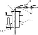
- Fig. 1is the front view of a kind of organic waste anaerobic reactor disclosed by the present invention
- FIG. 2is a top view of an anaerobic reactor for organic waste disclosed in the present invention.
- FIG. 3is a top view of a slag collecting tank of an anaerobic reactor for organic waste disclosed in the present invention
- FIG. 4is a cross-sectional view of a slag collecting tank of an anaerobic reactor for organic waste disclosed in the present invention
- FIG. 5is a structural diagram of a flushing water interface of an anaerobic reactor for organic waste disclosed in the present invention
- FIG. 6is a structural diagram of the bottom slag discharge port of an organic waste anaerobic reactor disclosed in the present invention.
- Reactor tank body1-1, tank top; 1-2, tank wall; 2, slag collection tank; 3, central agitator; 3-1, first paddle; 3-2, second paddle ;3-3. Stirring motor; 4. Feeding port; 5. Bottom discharging port; 6. Top discharging port; 7. Maintenance platform; 8. Manhole; 9. Bottom slag discharging port; 10. Flushing pipeline ;11, positive and negative pressure protector; 12, gas pressure sensor; 13, agitator inspection port; 14, biogas outlet; 15, manual ball valve; 16, solenoid valve; 17, slag discharge pipe; 18, reducer pipe; 19 , Tee pipe; 20. Pipe support.
- the terms “installed”, “connected” and “connected”should be understood in a broad sense, for example, it may be a fixed connection or a connectable connection.
- Detachable connection, or integral connectionmay be mechanical connection or electrical connection; may be direct connection, or indirect connection through an intermediate medium, or internal communication between two components.
- the present inventiondiscloses an anaerobic reactor for organic waste, including a reactor tank 1, a slag collecting tank 2 and a central agitator 3; , and grading is carried out along the circumferential direction, and the lowest end of the slag collecting tank 2 is connected with the top discharge port 6; the upper part of the reactor tank 1 corresponds to the slag collecting tank 2 surrounded by a plurality of flushing pipelines 10, and the lower part is provided with a A plurality of bottom slag discharge ports 9, the side wall of the reactor tank 1 is provided with a feed port 4 and a bottom discharge port 5, and the feed pipe passes through the feed port 4 and vertically in the reactor tank 1.
- the internal inclinationis at a certain angle; the central agitator 3 is arranged inside the reactor tank 1, and the central agitator 3 includes a first paddle 3-1 arranged under the liquid surface for stirring materials and a first paddle 3-1 arranged at the liquid surface for Second paddle 3-2 for cleaning scum.
- the processing capacity of the present inventionis 100 tons/day, the TS content is 8%-16%, and the organic waste slurry with particle size less than 10mm.
- the present inventionhas simple structure and convenient maintenance.
- the materialBy passing the feeding pipe through the feeding port 4 and then tilting it vertically and inwardly at a certain angle in the reactor tank 1, the material can better enter the flow field to form a certain turbulent flow, and at the same time Under the action of turbulent flow, the material can be better mixed into the reactor, so that the incoming material can contact the material in the tank more uniformly and quickly, effectively preventing partial precipitation caused by uneven specific gravity of the material, and improving the fermentation of the reactor.
- Efficiencyby setting the second blade 3-2 for cleaning the scum, the scum inside the tank can be collected to the position 1-2 of the tank wall under the action of the centrifugal force generated by the stirring of the blade, which is convenient for the scum collection tank 2 to remove the scum.
- the collection and dischargeimprove the reaction efficiency of the materials inside the tank and ensure the safe and reliable operation of the reactor.
- the diameter of the reactor tank 1 of the present inventionis not less than 16m, preferably 16m in the present invention
- the height of the straight section of the reactor tank 1is not less than 16.8m
- the height of the straight section of the present inventionis preferably 16.8m
- the tank top 1-1is a cone top design
- the cone top angleis not less than 20 °
- the cone top angle of the present inventionis preferably 20°.
- the effective volumeis preferably 3300m 3 .
- the slag collecting tank 2 of the present inventionis connected with the inner wall of the reactor tank 1 by welding, and the bottom elevations of the slag collecting tank 2 in the horizontal direction of the reactor tank 1 at 60° and 240° are 15.75m, the bottom elevation at 150° and 330° in the horizontal direction is 15.62m, the top elevation of the slag collecting tank 2 is 15.9m, the bottom elevation and the top elevation of the slag collecting tank 2 of the present invention are based on the tank bottom. Elevation, the slag collecting tank 2 is connected to the corresponding bottom discharge port 6 through the slag discharge pipeline at the 150° and 330° positions.
- the diameter of the slag discharge pipelineis preferably 0.2m. 6.
- the connected flangewherein the length of the slag discharge pipeline extending out of the reactor tank 1 along the horizontal direction is not less than 0.35m, and the length of the slag discharge pipeline extending out of the reactor tank 1 in the present invention is preferably 0.35m.
- the height of the feeding port 4 of the present invention from the groundis not less than 2.5m
- the setting height of the feeding port 4 of the present inventionis preferably 2.5m
- the feeding pipeenters the reactor tank after passing through the feeding port 3 horizontally.
- the feeding pipeis laid vertically upward after entering the reactor tank 1, and the laying tail of the feeding pipe is inclined at a certain angle to the inside of the reactor tank 1, and the inclined setting can not only make the material flow better.
- the fieldforms a certain turbulent flow, and at the same time, under the action of turbulence, the material can be mixed into the reactor better, so that the incoming material and the material in the tank are more uniformly contacted, which can effectively prevent partial precipitation caused by uneven specific gravity of the material, improve the fermentation efficiency of the reactor.
- the feeding speed of the present inventionis not less than 5 m/sec, and the feeding speed of the present invention is preferably 5 m/sec.
- the stirring motor 3-3 of the central agitator 3 of the present inventionis arranged on the top of the reactor tank 1, one end of the output shaft of the central agitator 3 is connected with the stirring motor 3-3, and the other end passes through the tank top 1-3.
- 1is placed inside the reactor tank 1, and the output shaft is sequentially installed with a first paddle 3-1 and a second paddle 3-2 from top to bottom.
- the installation method of each groupimproves the stirring efficiency of the reactor.
- the scum inside the reactor tank 1 at the liquid levelis collected to the tank wall 1 under the action of the centrifugal force generated by the stirring of the blades of the second paddle 3-2.
- the -2 positionis convenient for the collection of scum by the slag collecting tank 2, which ensures the safe and reliable operation of the reactor.
- the bottom discharge port 5 of the present inventionis arranged at the bottom of the reactor tank 1, and the discharge pipe is placed directly below the central agitator 3 after passing through the bottom discharge port 5, wherein the discharge pipe is in the reactor tank.
- the interior of the body 1is a horizontal straight pipe section, and the discharge pipe is horizontally arranged directly below the central agitator 3, which solves the problem that the material is easy to accumulate due to the weak flow field directly below the central agitator 3, and when the material is discharged under the action of gravity
- the materialhere will be preferentially discharged to prevent the dead zone due to deposition, which will cause the material to not be discharged and affect the reaction efficiency of the reactor.
- each flushing pipeline 10 of the present inventionis respectively arranged at 60°, 240°, 150°, and 330° directly above the slag collecting tank 2 in the circumferential direction, and each flushing pipeline 10 is preferably a DN50 pipe
- the DN50 pipelinepasses through the tank top 1-1 and extends inside the reactor tank 1, and there is a certain distance from the upper surface of the slag collecting tank 2.
- Each DN50 pipelineis provided with a manual ball valve 15 and a solenoid valve 16.
- the setting of the manual ball valve 15 and the solenoid valve 16 of the present inventionensures that when the solenoid valve 16 is overhauled or the solenoid valve 16 fails, the on-off of the pipeline can be controlled by the manual ball valve 15.
- the manual ball valve 15 of the present inventionis in the solenoid valve. 16 Set one before and after each.
- the bottom slag discharge ports 9 of the present inventionare arranged at an angle of 45°, 135°, 225°, and 315° along the bottom of the tank wall 1-2 of the reactor tank body 1; each The outlet of the bottom slag discharge port 9 is connected with a slag discharge pipe 17 through a connecting piece.
- the slag discharge pipe 17is inclined downward through the pipeline support 20, and the inclination angle is not greater than 45°.
- the inclination angle of the slag discharge pipe 17 in the present inventionis preferably 45°. °.
- each bottom slag discharge port 9is connected with a three-way pipe 19, and the two ends of the three-way pipe 19 are respectively connected with a slag discharge pipe 17 through an elbow and a reducing pipe 18, and two adjacent slag discharge pipes are connected.
- the included angle of 17is not greater than 90°, and the included angle of two adjacent slag discharge pipes 17 of the present invention is preferably 90°
- the present inventionalso includes a controller, a liquid level gauge, a gas pressure sensor 12 and a positive and negative pressure protector 11, wherein the liquid level gauge and the gas pressure sensor 12 are installed inside the reactor tank 1, and the positive and negative pressure protector 11 is installed On the top of the reactor tank 1, the liquid level gauge and the gas pressure sensor 12 are connected to the input end of the controller, and the positive and negative pressure protector 11 and the central stirrer 3 are connected to the output end of the controller.
- the protection range of the positive and negative pressure protector 11is -300pa ⁇ 2.5Kpa. When it is detected that the pressure inside the reactor tank 1 exceeds the protection range or is lower than the protection range, the positive and negative pressure protector 11 acts at this time, which improves the reaction safety and operational reliability of the device.
- the gas pressure sensor 12is used to monitor the biogas pressure inside the reactor tank 1 in real time, which further improves the safety of the reactor.
- a manual ball valve 15 and a solenoid valve 16are provided on the connecting pipelines with the feed port 4, the plurality of bottom slag discharge ports 9, the bottom discharge port 5, and the top discharge port 6, and each solenoid valve 16 is connected to the The output of the controller is connected.
- the present inventionis also provided with an inspection platform 7, a manhole 8, a mixer inspection port 13, a glass observation port and a biogas outlet 14, wherein the upper part of the tank top 1-1 corresponds to the central agitator.
- the position of the stirring motor 3-3 of the 3is provided with an agitator inspection port 13, and the upper part of the tank top 1-1 is also provided with an inspection platform 7 and a biogas outlet 14, and the tank wall of the reactor tank 1 corresponds to the bottom position of the central agitator.
- a glass observation portis also provided on the tank wall 1-2 on the same level as the slag collecting tank 2. The glass observation port can observe the scum inside the slag collecting tank and improve the fermentation efficiency of the reactor.
- the arrangement angle and height of the plurality of bottom slag outlets 9, the plurality of flushing pipelines 10 and the slag collecting tank 2can be adjusted according to the size of the specific reactor tank 1, so as to adapt to the specific reaction.
- the reactor tank 1ensures the fermentation efficiency of the reactor.
- the liquid level in the normal operation of the present inventionis 16m
- the feed port 4 and the central agitator 3when the liquid level rises to 16.2m, close the feed port 4, at this time the central agitator 3 starts to feed the material.
- the scum inside the reactor tank 1gathers on the tank wall 1-2.
- the operatorobserves the scum accumulation through the glass observation port, and controls to open the top discharge port 6 on the pipeline.
- the valves of the four flushing pipelines 10start to flush the slag collecting tank 2.
- the secondary feeding stepis consistent with the primary feeding step, and will not be repeated again;
- bottom dischargewhen the reactor runs for 15 days, before opening the feed port 4, it is necessary to open the valve on the bottom discharge port 5, and perform the bottom discharge work for 2 minutes. After the bottom discharge work is completed, again Repeat the above-mentioned steps 2 and 3, and carry out material addition and fermentation work;
Landscapes
- Chemical & Material Sciences (AREA)
- Engineering & Computer Science (AREA)
- Health & Medical Sciences (AREA)
- Life Sciences & Earth Sciences (AREA)
- Bioinformatics & Cheminformatics (AREA)
- Organic Chemistry (AREA)
- Zoology (AREA)
- Biotechnology (AREA)
- Wood Science & Technology (AREA)
- Microbiology (AREA)
- Biomedical Technology (AREA)
- Sustainable Development (AREA)
- Medicinal Chemistry (AREA)
- Oil, Petroleum & Natural Gas (AREA)
- Biochemistry (AREA)
- General Engineering & Computer Science (AREA)
- General Health & Medical Sciences (AREA)
- Genetics & Genomics (AREA)
- General Chemical & Material Sciences (AREA)
- Purification Treatments By Anaerobic Or Anaerobic And Aerobic Bacteria Or Animals (AREA)
Abstract
Description
Translated fromChinese本发明涉及有机垃圾处理技术领域,具体涉及一种有机垃圾厌氧反应器。The invention relates to the technical field of organic waste treatment, in particular to an organic waste anaerobic reactor.
随着经济社会发展和物质消费水平大幅度提高,我国生活垃圾产量迅速增长,环境隐患日益突出,已经成为新兴城镇化发展的制约因素。遵循减量化、资源化、无害化的原则,实施生活垃圾分类,可以有效改善城乡环境,促进资源回收利用,加快“两型社会”建设,提高新型城镇化质量和生态文明建设水平。With the economic and social development and the substantial increase in the level of material consumption, the output of domestic waste in my country has grown rapidly, and environmental hidden dangers have become increasingly prominent, which has become a restrictive factor for the development of emerging urbanization. Following the principles of reduction, recycling, and harmlessness, the implementation of household waste classification can effectively improve the urban and rural environment, promote resource recycling, accelerate the construction of a "two-oriented society", and improve the quality of new urbanization and the level of ecological civilization construction.
国务院办公厅和住房城乡建设部分别发布了《生活垃圾分类制度实施方案》和《住房城乡建设部关于加快推进部分重点城市生活垃圾分类工作的通知》。确定了北京、天津、上海等46个重点城市先行实施生活垃圾分类。46个重点城市基本建成生活垃圾分类处理系统,基本形成相应的法律法规和标准体系,形成一批可复制、可推广的模式。在进入焚烧和填埋设施之前,可回收物和易腐垃圾的回收利用率合计达到35%以上。其中有机垃圾(有机固废)主要包括:相关单位食堂、宾馆、饭店、小区、果蔬市场、农田等产生的有机质垃圾等。The General Office of the State Council and the Ministry of Housing and Urban-Rural Development have respectively issued the "Implementation Plan for Domestic Waste Classification System" and the "Notice of the Ministry of Housing and Urban-Rural Development on Accelerating the Promotion of Domestic Waste Classification in Some Key Cities". 46 key cities including Beijing, Tianjin and Shanghai have been determined to implement household waste classification first. 46 key cities have basically built a household waste classification and treatment system, basically formed corresponding laws, regulations and standard systems, and formed a batch of replicable and popularized models. The combined recycling rate of recyclables and perishable waste reaches more than 35% before entering incineration and landfill facilities. Among them, organic waste (organic solid waste) mainly includes: organic waste generated by relevant units such as canteens, hotels, restaurants, communities, fruit and vegetable markets, and farmland.
有机垃圾因其易腐发臭、易生物降解等特点,不宜直接填埋和焚烧,因此急需要一种结构简单、发酵效率高且运行安全可靠的有机垃圾厌氧反应器。Organic waste is not suitable for direct landfill and incineration because of its perishable, odorous, and biodegradable characteristics. Therefore, an anaerobic reactor for organic waste with simple structure, high fermentation efficiency and safe and reliable operation is urgently needed.
发明内容SUMMARY OF THE INVENTION
针对现有技术中存在的不足之处,本发明提供了一种有机垃圾厌氧反应器。Aiming at the deficiencies in the prior art, the present invention provides an anaerobic reactor for organic waste.
本发明公开了一种有机垃圾厌氧反应器,包括反应器罐体、中央搅拌器和集渣槽;The invention discloses an anaerobic reactor for organic waste, comprising a reactor tank, a central stirrer and a slag collecting tank;
所述集渣槽环布在所述反应器罐体内壁上部,且沿周向进行放坡,所述集渣槽的最低端与顶部排料口连接;The slag collecting trough is annularly arranged on the upper part of the inner wall of the reactor tank, and is sloped along the circumferential direction, and the lowest end of the slag collecting trough is connected to the top discharge port;
所述反应器罐体的上部对应所述集渣槽环布有多个冲洗管路,下部设有 有多个底部排渣口,所述反应器罐体的侧壁上设有进料口和底部出料口,进料管穿过所述进料口后在所述反应器罐体内竖直向内倾斜一定角度;The upper part of the reactor tank body is provided with a plurality of flushing pipelines corresponding to the slag collecting tank, the lower part is provided with a plurality of bottom slag discharge ports, and the side wall of the reactor tank body is provided with feed ports and The bottom discharge port, the feed pipe is inclined vertically and inwardly in the reactor tank at a certain angle after passing through the feed port;
所述中央搅拌器设置在所述反应器罐体内部,所述中央搅拌器包括设在液面下的用于搅拌物料的第一桨叶和设在液面处的用于清理浮渣的第二桨叶。The central agitator is arranged inside the reactor tank, and the central agitator includes a first paddle set below the liquid level for stirring materials and a second paddle set at the liquid level for cleaning scum. Two blades.
作为本发明的进一步改进,所述反应器罐体的直径不小于16m,直段高度不小于16.8m;As a further improvement of the present invention, the diameter of the reactor tank is not less than 16m, and the height of the straight section is not less than 16.8m;
所述反应器罐体的顶部为锥顶结构,所述锥顶角度不小于20°。The top of the reactor tank is a cone-top structure, and the cone-top angle is not less than 20°.
作为本发明的进一步改进,所述集渣槽与所述反应器罐体内壁通过焊接方式连接,所述集渣槽在环向60°和240°的底部标高为15.75m,在环向150°和330°的底部标高为15.62m,所述集渣槽的顶部标高为15.9m;所述底部标高、所述顶部标高均以罐底为基准0标高;As a further improvement of the present invention, the slag collecting tank is connected with the inner wall of the reactor tank by welding, and the bottom elevation of the slag collecting tank at 60° and 240° in the circumferential direction is 15.75m, and at 150° in the circumferential direction The bottom elevation of 330° and 330° is 15.62m, and the top elevation of the slag collecting tank is 15.9m; the bottom elevation and the top elevation are all based on the tank bottom as the base 0 elevation;
所述集渣槽在环向150°、330°位置与所述顶部排料口连接,所述集渣槽的截面为U型。The slag collecting trough is connected to the top discharge port at 150° and 330° circumferential positions, and the cross-section of the slag collecting trough is U-shaped.
作为本发明的进一步改进,多个所述冲洗管路分别环向设置在集渣槽正上方的60°、240°、150°、330°处;As a further improvement of the present invention, a plurality of the flushing pipelines are respectively arranged circumferentially at 60°, 240°, 150°, and 330° right above the slag collecting tank;
所述冲洗管路为DN50管,所述DN50管上依次设有手动球阀和电磁阀。The flushing pipeline is a DN50 pipe, and a manual ball valve and a solenoid valve are arranged on the DN50 pipe in sequence.
作为本发明的进一步改进,多个所述底部排渣口沿着所述反应器罐体罐壁底部环向布置角度为45°、135°、225°、315°;As a further improvement of the present invention, the plurality of bottom slag discharge ports are arranged at angles of 45°, 135°, 225°, and 315° along the bottom of the tank wall of the reactor tank;
每个所述底部排渣口的出口处均通过连接件连接有排渣管,所述排渣管通过管道支架向下倾斜设置,所述倾斜角度不大于45°。The outlet of each bottom slag discharge port is connected with a slag discharge pipe through a connecting piece, and the slag discharge pipe is inclined downwardly through a pipe support, and the inclination angle is not greater than 45°.
作为本发明的进一步改进,所述进料口距离地面的设置高度不小于2.5m,进料管水平穿过所述进料口后进入所述反应器罐体内部;As a further improvement of the present invention, the setting height of the feeding port from the ground is not less than 2.5m, and the feeding pipe enters the inside of the reactor tank after passing through the feeding port horizontally;
所述进料管在所述反应器罐体内部做竖直向上设计,所述进料管的尾部向内倾斜。The feed pipe is designed vertically upward inside the reactor tank, and the tail of the feed pipe is inclined inward.
作为本发明的进一步改进,所述底部出料口设置在所述反应器罐体底部,出料管穿过所述出料口后置于所述中央搅拌器的正下方,所述出料管在所述反应器罐体内部为水平直管段。As a further improvement of the present invention, the bottom discharge port is arranged at the bottom of the reactor tank, and the discharge pipe is placed directly under the central agitator after passing through the discharge port. Inside the reactor tank is a horizontal straight pipe section.
作为本发明的进一步改进,所述中央搅拌器的电机端置于所述反应器罐体的顶部,所述中央搅拌器的输出轴穿过所述反应器罐体顶部后进入所述反应器罐体内部;As a further improvement of the present invention, the motor end of the central agitator is placed on the top of the reactor tank, and the output shaft of the central agitator enters the reactor tank after passing through the top of the reactor tank inside the body;
所述输出轴上沿竖直方向依次设有第一桨叶和第二桨叶。A first paddle and a second paddle are sequentially arranged on the output shaft along the vertical direction.
作为本发明的进一步改进,还包括控制器、液位计、压力传感器和正负压保护器;As a further improvement of the present invention, it also includes a controller, a liquid level gauge, a pressure sensor and a positive and negative pressure protector;
所述液位计和所述压力传感器安装在所述反应器罐体内部,所述正负压保护器安装在所述反应器罐体顶部;The liquid level gauge and the pressure sensor are installed inside the reactor tank, and the positive and negative pressure protectors are installed on the top of the reactor tank;
所述液位计、所述压力传感器与所述控制器的输入端连接,所述正负压保护器、所述中央搅拌器与所述控制器的输出端连接。The liquid level gauge and the pressure sensor are connected to the input end of the controller, and the positive and negative pressure protectors and the central agitator are connected to the output end of the controller.
作为本发明的进一步改进,与所述进料口、多个所述底部排渣口、所述底部出料口、所述顶部排料口的连接管路上均设有手动球阀和电磁阀,每个所述电磁阀均与所述控制器的输出端连接。As a further improvement of the present invention, a manual ball valve and a solenoid valve are provided on the connecting pipelines with the feed port, the plurality of bottom slag discharge ports, the bottom discharge port, and the top discharge port. Each of the solenoid valves is connected to the output end of the controller.
与现有技术相比,本发明的有益效果为:Compared with the prior art, the beneficial effects of the present invention are:
本发明结构简单,通过将进料管穿过进料口后在反应器罐体内竖直向内倾斜一定角度,不仅可以使物料更好的进入流场形成一定的湍流,同时在湍流的作用下可以使物料更好的混入反应器,使进入的物料与罐内的物料接触的更均匀,更快速,有效的防止因物料比重不均导致的部分沉淀,提高了反应器的发酵效率;The present invention has a simple structure, and by passing the feed pipe through the feed port and inclining it vertically and inwardly at a certain angle in the reactor tank, not only can the material enter the flow field better to form a certain turbulent flow, but also under the action of the turbulent flow It can make the material better mixed into the reactor, make the incoming material contact with the material in the tank more uniformly and quickly, effectively prevent partial precipitation caused by the uneven specific gravity of the material, and improve the fermentation efficiency of the reactor;
本发明通过设置清理浮渣的第二桨叶,使罐体内部的浮渣在叶片搅动产生的离心力的作用下汇集到罐壁位置,方便集渣槽对浮渣的收集和排出,提高了罐体内部的物料的反应效率,保证了反应器的运行安全可靠;In the present invention, the second paddle for cleaning scum is arranged, so that the scum inside the tank is collected to the position of the tank wall under the action of the centrifugal force generated by the stirring of the blade, which facilitates the collection and discharge of the scum by the slag collecting tank, and improves the efficiency of the tank. The reaction efficiency of the materials inside the body ensures the safe and reliable operation of the reactor;
本发明通过将出料管设置一段水平管,水平管一端设置在中央搅拌器正下方,由于中央搅拌器正下方流场较弱物料易堆积,在重力的作用下当物料出料时会优先排出此处物料,以防止因沉积产生死区物料无法排出,提高了反应器的反应效率。In the present invention, a section of horizontal pipe is arranged in the discharge pipe, and one end of the horizontal pipe is arranged directly under the central agitator. Since the flow field directly under the central agitator is weak and the materials are easy to accumulate, the materials will be preferentially discharged under the action of gravity when they are discharged. The material here can prevent the dead zone material from being discharged due to deposition, which improves the reaction efficiency of the reactor.
图1为本发明公开的一种有机垃圾厌氧反应器主视图;Fig. 1 is the front view of a kind of organic waste anaerobic reactor disclosed by the present invention;
图2为本发明公开的一种有机垃圾厌氧反应器俯视图;2 is a top view of an anaerobic reactor for organic waste disclosed in the present invention;
图3为本发明公开的一种有机垃圾厌氧反应器的集渣槽俯视图;3 is a top view of a slag collecting tank of an anaerobic reactor for organic waste disclosed in the present invention;
图4为本发明公开的一种有机垃圾厌氧反应器的集渣槽截面图;4 is a cross-sectional view of a slag collecting tank of an anaerobic reactor for organic waste disclosed in the present invention;
图5为本发明公开的一种有机垃圾厌氧反应器的冲洗水接口结构图;5 is a structural diagram of a flushing water interface of an anaerobic reactor for organic waste disclosed in the present invention;
图6为本发明公开的一种有机垃圾厌氧反应器的底部排渣口结构图。FIG. 6 is a structural diagram of the bottom slag discharge port of an organic waste anaerobic reactor disclosed in the present invention.
图中:In the picture:
1、反应器罐体;1-1、罐顶;1-2、罐壁;2、集渣槽;3、中央搅拌器;3-1、第一桨叶;3-2、第二桨叶;3-3、搅拌电机;4、进料口;5、底部出料口;6、顶部排料口;7、检修平台;8、人孔;9、底部排渣口;10、冲洗管路;11、正负压保护器;12、气体压力传感器;13、搅拌器检修口;14、沼气出口;15、手动球阀;16、电磁阀;17、排渣管;18、变径管;19、三通管;20、管道支架。1. Reactor tank body; 1-1, tank top; 1-2, tank wall; 2, slag collection tank; 3, central agitator; 3-1, first paddle; 3-2, second paddle ;3-3. Stirring motor; 4. Feeding port; 5. Bottom discharging port; 6. Top discharging port; 7. Maintenance platform; 8. Manhole; 9. Bottom slag discharging port; 10. Flushing pipeline ;11, positive and negative pressure protector; 12, gas pressure sensor; 13, agitator inspection port; 14, biogas outlet; 15, manual ball valve; 16, solenoid valve; 17, slag discharge pipe; 18, reducer pipe; 19 , Tee pipe; 20. Pipe support.
为使本发明实施例的目的、技术方案和优点更加清楚,下面将结合本发明实施例中的附图,对本发明实施例中的技术方案进行清楚、完整地描述,显然,所描述的实施例是本发明的一部分实施例,而不是全部的实施例。基于本发明中的实施例,本领域普通技术人员在没有做出创造性劳动的前提下所获得的所有其他实施例,都属于本发明保护的范围。In order to make the purposes, technical solutions and advantages of the embodiments of the present invention clearer, the technical solutions in the embodiments of the present invention will be clearly and completely described below with reference to the accompanying drawings in the embodiments of the present invention. Obviously, the described embodiments These are some embodiments of the present invention, but not all embodiments. Based on the embodiments of the present invention, all other embodiments obtained by those of ordinary skill in the art without creative work fall within the protection scope of the present invention.
在本发明的描述中,需要说明的是,术语“中心”、“上”、“下”、“左”、“右”、“竖直”、“水平”、“内”、“外”等指示的方位或位置关系为基于附图所示的方位或位置关系,仅是为了便于描述本发明和简化描述,而不是指示或暗示所指的装置或元件必须具有特定的方位、以特定的方位构造和操作,因此不能理解为对本发明的限制。此外,术语“第一”、“第二”、“第三”仅用于描述目的,而不能理解为指示或暗示相对重要性。In the description of the present invention, it should be noted that the terms "center", "upper", "lower", "left", "right", "vertical", "horizontal", "inner", "outer", etc. The indicated orientation or positional relationship is based on the orientation or positional relationship shown in the accompanying drawings, which is only for the convenience of describing the present invention and simplifying the description, rather than indicating or implying that the indicated device or element must have a specific orientation or a specific orientation. construction and operation, and therefore should not be construed as limiting the invention. Furthermore, the terms "first", "second", and "third" are used for descriptive purposes only and should not be construed to indicate or imply relative importance.
在本发明的描述中,还需要说明的是,除非另有明确的规定和限定,术语“安装”、“相连”、“连接”应做广义理解,例如,可以是固定连接,也可以是可拆卸连接,或一体地连接;可以是机械连接,也可以是电连接;可以是直接相连,也可以通过中间媒介间接相连,可以是两个元件内部的连通。对于本领域的普通技术人员而言,可以具体情况理解上述术语在本发明中的具体含义。In the description of the present invention, it should also be noted that, unless otherwise expressly specified and limited, the terms "installed", "connected" and "connected" should be understood in a broad sense, for example, it may be a fixed connection or a connectable connection. Detachable connection, or integral connection; may be mechanical connection or electrical connection; may be direct connection, or indirect connection through an intermediate medium, or internal communication between two components. For those of ordinary skill in the art, the specific meanings of the above terms in the present invention can be understood in specific situations.
下面结合附图对本发明做进一步的详细描述:Below in conjunction with accompanying drawing, the present invention is described in further detail:
如图1所示,本发明公开了一种有机垃圾厌氧反应器,包括反应器罐体1、集渣槽2和中央搅拌器3;集渣槽2环布在反应器罐体1内壁上部,且沿周向 进行放坡,集渣槽2的最低端与顶部排料口6连接;反应器罐体1的上部对应集渣槽2环布有多个冲洗管路10,下部设有有多个底部排渣口9,反应器罐体1的侧壁上设有进料口4和底部出料口5,进料管穿过进料口4后在反应器罐体1内竖直向内倾斜一定角度;中央搅拌器3设置在反应器罐体1内部,中央搅拌器3包括设在液面下的用于搅拌物料的第一桨叶3-1和设在液面处的用于清理浮渣的第二桨叶3-2。本发明的处理量为100吨/天,TS含量为8%-16%,粒径小于10mm的有机垃圾浆液。As shown in Figure 1, the present invention discloses an anaerobic reactor for organic waste, including a
本发明结构简单,维护方便,通过将进料管穿过进料口4后在反应器罐体1内竖直向内倾斜一定角度,使物料更好的进入流场形成一定的湍流,同时在湍流的作用下可以使物料更好的混入反应器,使进入的物料与罐内的物料接触的更均匀,更快速,有效的防止因物料比重不均导致的部分沉淀,提高了反应器的发酵效率,通过设置清理浮渣的第二桨叶3-2,使罐体内部的浮渣在叶片搅动产生的离心力的作用下汇集到罐壁1-2位置,方便集渣槽2对浮渣的收集和排出,提高了罐体内部的物料的反应效率,保证了反应器的运行安全可靠。The present invention has simple structure and convenient maintenance. By passing the feeding pipe through the feeding
具体的:specific:
如图1所示,本发明的反应器罐体1的直径不小于16m,本发明优选16m,反应器罐体1的直段高度不小于16.8m,本发明直段高度优选16.8m,反应器罐顶1-1为锥顶设计,锥顶角度不小于20°,本发明锥顶角度优选20°本发明的反应器罐体1的有效容积不小于3300m3,本发明的反应器罐体1的有效容积优选3300m3。As shown in Fig. 1, the diameter of the
如图2~4所示,本发明的集渣槽2与反应器罐体1内壁通过焊接方式连接,集渣槽2在反应器罐体1的水平方向的60°和240°的底部标高为15.75m,在水平方向的150°和330°位置底部标高为15.62m,集渣槽2的顶部标高为15.9m,本发明的集渣槽2的底部标高和顶部标高均以罐底为基准0标高,集渣槽2在150°和330°位置均通过排渣管路与对应的底部出料口6连接,排渣管路直径优选0.2m,排渣管路尾部设有与底部出料口6连接的法兰盘,其中排渣管路沿水平方向伸出反应器罐体1的长度不小于0.35m,本发明排渣管路伸出反应器罐体1长度优选0.35m。As shown in FIGS. 2 to 4 , the
如图1所示,本发明进料口4距离地面的设置高度不小于2.5m,本发明 进料口4设置高度优选2.5m,进料管水平穿过进料口3后进入到反应器罐体1内部,进料管在进入反应器罐体1内部后竖直向上铺设,进料管的铺设尾部向反应器罐体1内部倾斜一定角度,倾斜设置,不仅可以使物料更好的进入流场形成一定的湍流,同时在湍流的作用下也可以是物料更好的混入反应器,使进入的物料与罐内的物料接触的更均匀,有效防止因物料比重不均导致的部分沉淀,提高了反应器的发酵效率。本发明进料速度不低于5m/秒,本发明进料速度优选5m/秒。As shown in FIG. 1 , the height of the feeding
进一步的,本发明的中央搅拌器3的搅拌电机3-3设置在反应器罐体1的顶部,中央搅拌器3的输出轴一端与搅拌电机3-3连接,另一端穿过罐顶1-1置于反应器罐体1内部,输出轴自上向下依次安装有第一桨叶3-1和第二桨叶3-2,第一桨叶3-1在实际安装时,可以采取两个为一组的安装方式,提高反应器的搅拌效率,反应器罐体1内部的位于液面的浮渣在第二桨叶3-2的叶片搅动产生的离心力的作用下汇集到罐壁1-2位置,方便集渣槽2对浮渣的收集,保证了反应器的运行安全可靠。Further, the stirring motor 3-3 of the
进一步的,本发明的底部出料口5设置在反应器罐体1的底部,出料管穿过底部出料口5后置于中央搅拌器3的正下方,其中出料管在反应器罐体1内部为水平直管段,出料管水平设置在中央搅拌器3的正下方,解决了由于中央搅拌器3的正下方流场较弱物料易堆积,在重力的作用下当物料出料时会优先排出此处物料,以防止因沉积产生死区,导致物料无法排出,影响反应器的反应效率。Further, the
如图5所示,本发明的多个冲洗管路10环向分别设置在集渣槽2正上方的60°、240°、150°、330°处,每个冲洗管路10均优选DN50管路,DN50管路穿过罐顶1-1后伸出在反应器罐体1内部,且距离集渣槽2上表面存在一定距离,每条DN50管路均设置有手动球阀15和电磁阀16,本发明手动球阀15和电磁阀16的设置,保证了在对电磁阀16进行检修或者电磁阀16出现故障时,可以通过手动球阀15控制管路的通断,本发明手动球阀15在电磁阀16前后各设置一个。As shown in FIG. 5 , the
如图2和图6所示,本发明的底部排渣口9沿着反应器罐体1的罐壁1-2底部环向布置角度为45°、135°、225°、315°;每个底部排渣口9的出口处均通过连接件连接有排渣管17,排渣管17通过管道支架20向下倾斜设置, 倾斜角度不大于45°,本发明排渣管17的倾斜角度优选45°。As shown in FIG. 2 and FIG. 6 , the bottom
进一步的,每个底部排渣口9的出口处均连接有三通管19,三通管19的两端分别通过弯头和变径管18连接有排渣管17,相邻两个排渣管17的夹角角度不大于90°,本发明相邻两个排渣管17的夹角角度优选90°Further, the outlet of each bottom
进一步的,本发明还包括控制器、液位计、气体压力传感器12和正负压保护器11,其中液位计和气体压力传感器12安装在反应器罐体1内部,正负压保护器11安装在反应器罐体1的顶部,液位计、气体压力传感器12与控制器的输入端连接,正负压保护器11、中央搅拌器3与控制器的输出端连接。正负压保护器11的保护范围为-300pa~2.5Kpa,当检测到反应器罐体1内部的压力超过保护范围或低于保护范围时,此时正负压保护器11动作,提高了反应器的安全、运行可靠性。气体压力传感器12用于对反应器罐体1内部的沼气压力进行实时监测,进一步提高了反应器的安全性。Further, the present invention also includes a controller, a liquid level gauge, a
进一步的,与进料口4、多个底部排渣口9、底部出料口5、顶部排料口6的连接管路上均设有手动球阀15和电磁阀16,每个电磁阀16均与控制器的输出端连接。Further, a
进一步的,如图1和图2所示,本发明还设置有检修平台7、人孔8、搅拌器检修口13、玻璃观察口和沼气出口14,其中罐顶1-1上部对应中央搅拌器3的搅拌电机3-3的位置设有搅拌器检修口13,罐顶1-1上部还设有检修平台7和沼气出口14,在反应器罐体1的罐壁对应中央搅拌器底部位置还设有人孔8,人孔8的设计,实现了对反应器罐体1内部的物料和废渣的观察。与集渣槽2同一水平面的罐壁1-2位置还设有玻璃观察口,玻璃观察口设置实现了对集渣槽内部浮渣的观察,提高了反应器的发酵效率。Further, as shown in Figure 1 and Figure 2, the present invention is also provided with an
进一步的,本发明中多个底部排渣口9、多个冲洗管路10和集渣槽2的布置角度和高度均可以根据具体的反应器罐体1的尺寸进行调整,以适应具体的反应器罐体1,保证反应器的发酵效率。Further, in the present invention, the arrangement angle and height of the plurality of
本实施例的使用方法:How to use this embodiment:
1)、初始状态:中央搅拌器3、进料口4、底部出料口5、顶部排料口6、多个底部排渣口9、冲洗管路10、沼气出口14均处于关闭状态;1), the initial state: the
2)、一次加料:本发明正常运行液位为16m,打开进料口4和中央搅拌器3,当液位上升到16.2m时,关闭进料口4,此时中央搅拌器3开始对物料 进行搅拌,搅拌2小时后,反应器罐体1内部的浮渣聚集到罐壁1-2处,此时操作员通过玻璃观察口观察到浮渣聚集情况,控制打开顶部排料口6管路上的阀门开始排渣,当反应器罐体1内部液位下降到16.1m时,此时打开四个冲洗管路10的阀门,开始对集渣槽2进行冲洗,当反应器罐体1内部液位下降到15.9-16m时,关闭顶部排料口6管路上的阀门,再关闭4个冲洗管路10的阀门,停止冲洗和排渣工作,发酵反应过程中,沼气出口14处于打开状态;2), one feeding: the liquid level in the normal operation of the present invention is 16m, open the
3)、二次加料:二次加料步骤与一次加料步骤一致,再次不做赘述;3), secondary feeding: the secondary feeding step is consistent with the primary feeding step, and will not be repeated again;
4)、底部出料:当反应器运行15天后,在打开进料口4之前,需要打开底部出料口5上的阀门,进行2分钟的底部排料工作,底部排料工作完成后,再次重复上述步骤二和步骤三,进行物料添加和发酵工作;4), bottom discharge: when the reactor runs for 15 days, before opening the
5)、底部排渣;当反应器运行半年后,在打开进料口4之前,需要先打开底部排渣口9管路上的阀门,开始对反应器罐体1内部进行3-5分钟的排渣工作,排渣工作完成后,进行物料添加和发酵工作。5), bottom slag discharge; when the reactor runs for half a year, before opening the
以上仅为本发明的优选实施例而已,并不用于限制本发明,对于本领域的技术人员来说,本发明可以有各种更改和变化。凡在本发明的精神和原则之内,所作的任何修改、等同替换、改进等,均应包含在本发明的保护范围之内。The above are only preferred embodiments of the present invention, and are not intended to limit the present invention. For those skilled in the art, the present invention may have various modifications and changes. Any modification, equivalent replacement, improvement, etc. made within the spirit and principle of the present invention shall be included within the protection scope of the present invention.
Claims (10)
Translated fromChinesePriority Applications (1)
| Application Number | Priority Date | Filing Date | Title |
|---|---|---|---|
| ZA2023/04101AZA202304101B (en) | 2021-03-11 | 2023-04-03 | Organic waste anaerobic reactor |
Applications Claiming Priority (4)
| Application Number | Priority Date | Filing Date | Title |
|---|---|---|---|
| CN202120520057.X | 2021-03-11 | ||
| CN202110265780.2 | 2021-03-11 | ||
| CN202110265780.2ACN112852600A (en) | 2021-03-11 | 2021-03-11 | Organic garbage anaerobic reactor |
| CN202120520057.XUCN215886991U (en) | 2021-03-11 | 2021-03-11 | Organic garbage anaerobic reactor |
Publications (1)
| Publication Number | Publication Date |
|---|---|
| WO2022188224A1true WO2022188224A1 (en) | 2022-09-15 |
Family
ID=83227288
Family Applications (1)
| Application Number | Title | Priority Date | Filing Date |
|---|---|---|---|
| PCT/CN2021/084853CeasedWO2022188224A1 (en) | 2021-03-11 | 2021-04-01 | Organic waste anaerobic reactor |
Country Status (2)
| Country | Link |
|---|---|
| WO (1) | WO2022188224A1 (en) |
| ZA (1) | ZA202304101B (en) |
Cited By (5)
| Publication number | Priority date | Publication date | Assignee | Title |
|---|---|---|---|---|
| CN112852600A (en)* | 2021-03-11 | 2021-05-28 | 北京高能时代环境技术股份有限公司 | Organic garbage anaerobic reactor |
| CN115572658A (en)* | 2022-09-20 | 2023-01-06 | 北京时代桃源环境科技股份有限公司 | System and method for removing anaerobic scum and sediment |
| CN116764578A (en)* | 2023-07-19 | 2023-09-19 | 浙江宏达化学制品有限公司 | Preparation device and preparation method of fluorescent whitening agent |
| CN118788286A (en)* | 2024-09-12 | 2024-10-18 | 上海数郜机电有限公司 | A gas lift liquid collection stirring reactor |
| CN119186303A (en)* | 2024-11-22 | 2024-12-27 | 新乡市恒星科技有限责任公司 | Blending equipment for lubricating oil production |
Citations (8)
| Publication number | Priority date | Publication date | Assignee | Title |
|---|---|---|---|---|
| US4157958A (en)* | 1978-03-17 | 1979-06-12 | Chow Bernard H | Inverted vessel processing method for the production of methane gas |
| JP2005013845A (en)* | 2003-06-25 | 2005-01-20 | Sinto Brator Co Ltd | Scum disintegrator |
| CN202148310U (en)* | 2011-08-10 | 2012-02-22 | 类成明 | Straw methane reactor |
| CN102399683A (en)* | 2010-09-10 | 2012-04-04 | 辽宁北方环境保护有限公司 | Novel upflow anaerobic reactor |
| CN203411537U (en)* | 2013-08-27 | 2014-01-29 | 深圳市朗坤环保有限公司 | Anaerobic tank with scum discharging function |
| CN106085837A (en)* | 2016-06-29 | 2016-11-09 | 上海浦东环保发展有限公司 | A kind of equipment for changing food waste wet type anaerobism producing methane |
| CN209619356U (en)* | 2019-01-25 | 2019-11-12 | 湖北农谷环能科技有限公司 | A kind of marsh gas fermenting system |
| CN210085449U (en)* | 2019-01-30 | 2020-02-18 | 安徽九华环保科技有限公司 | Raw material processing device for straw methane station |
- 2021
- 2021-04-01WOPCT/CN2021/084853patent/WO2022188224A1/ennot_activeCeased
- 2023
- 2023-04-03ZAZA2023/04101Apatent/ZA202304101B/enunknown
Patent Citations (8)
| Publication number | Priority date | Publication date | Assignee | Title |
|---|---|---|---|---|
| US4157958A (en)* | 1978-03-17 | 1979-06-12 | Chow Bernard H | Inverted vessel processing method for the production of methane gas |
| JP2005013845A (en)* | 2003-06-25 | 2005-01-20 | Sinto Brator Co Ltd | Scum disintegrator |
| CN102399683A (en)* | 2010-09-10 | 2012-04-04 | 辽宁北方环境保护有限公司 | Novel upflow anaerobic reactor |
| CN202148310U (en)* | 2011-08-10 | 2012-02-22 | 类成明 | Straw methane reactor |
| CN203411537U (en)* | 2013-08-27 | 2014-01-29 | 深圳市朗坤环保有限公司 | Anaerobic tank with scum discharging function |
| CN106085837A (en)* | 2016-06-29 | 2016-11-09 | 上海浦东环保发展有限公司 | A kind of equipment for changing food waste wet type anaerobism producing methane |
| CN209619356U (en)* | 2019-01-25 | 2019-11-12 | 湖北农谷环能科技有限公司 | A kind of marsh gas fermenting system |
| CN210085449U (en)* | 2019-01-30 | 2020-02-18 | 安徽九华环保科技有限公司 | Raw material processing device for straw methane station |
Cited By (5)
| Publication number | Priority date | Publication date | Assignee | Title |
|---|---|---|---|---|
| CN112852600A (en)* | 2021-03-11 | 2021-05-28 | 北京高能时代环境技术股份有限公司 | Organic garbage anaerobic reactor |
| CN115572658A (en)* | 2022-09-20 | 2023-01-06 | 北京时代桃源环境科技股份有限公司 | System and method for removing anaerobic scum and sediment |
| CN116764578A (en)* | 2023-07-19 | 2023-09-19 | 浙江宏达化学制品有限公司 | Preparation device and preparation method of fluorescent whitening agent |
| CN118788286A (en)* | 2024-09-12 | 2024-10-18 | 上海数郜机电有限公司 | A gas lift liquid collection stirring reactor |
| CN119186303A (en)* | 2024-11-22 | 2024-12-27 | 新乡市恒星科技有限责任公司 | Blending equipment for lubricating oil production |
Also Published As
| Publication number | Publication date |
|---|---|
| ZA202304101B (en) | 2023-07-26 |
Similar Documents
| Publication | Publication Date | Title |
|---|---|---|
| WO2022188224A1 (en) | Organic waste anaerobic reactor | |
| CN102212462B (en) | Solid phase and liquid phase integrated methane fermenting device | |
| CN101949271B (en) | Low-temperature vehicle-mounted oil drilling fluid purifying system during drilling and repairing | |
| CN108532912A (en) | Corridor restaurant garbage treating system | |
| CN106085837A (en) | A kind of equipment for changing food waste wet type anaerobism producing methane | |
| CN112852600A (en) | Organic garbage anaerobic reactor | |
| CN205973934U (en) | Sewage treatment device | |
| CN110759500A (en) | Kitchen waste vacuum treatment system and working method | |
| CN207342324U (en) | A kind of kitchen oil separation filter device | |
| CN215886991U (en) | Organic garbage anaerobic reactor | |
| CN202087572U (en) | Complete equipment used for resource recovery of kitchen garbage | |
| CN101962599A (en) | Complete equipment for refining commercial grease by utilizing illegal cooking oil and method thereof | |
| CN209210475U (en) | A new high-efficiency UASB water treatment equipment | |
| CN103722006A (en) | Organo-chlorine pesticide contaminated soil synergism eluting system | |
| CN201648378U (en) | An anaerobic reaction device dedicated to kitchen waste | |
| CN208473239U (en) | A kind of corridor restaurant garbage treating system | |
| CN201010650Y (en) | Multifunctional biogas tank | |
| CN207242560U (en) | A kind of lime white prepares storage device | |
| CN116371886A (en) | A food waste treatment system | |
| CN213653678U (en) | Environment-friendly energy-saving building drainage structure | |
| CN204601707U (en) | Solidliquid mixture extraction and isolation device | |
| CN217912138U (en) | Organic garbage fine-separation pulping device | |
| CN106119290A (en) | A kind of ring medium ring two-stage integral anaerobic fermentation process | |
| CN106119092A (en) | A kind of restaurant garbage treating system | |
| CN207828316U (en) | A kind of firedamp gas equipment of processing rubbish from cooking |
Legal Events
| Date | Code | Title | Description |
|---|---|---|---|
| 121 | Ep: the epo has been informed by wipo that ep was designated in this application | Ref document number:21929696 Country of ref document:EP Kind code of ref document:A1 | |
| NENP | Non-entry into the national phase | Ref country code:DE | |
| 32PN | Ep: public notification in the ep bulletin as address of the adressee cannot be established | Free format text:NOTING OF LOSS OF RIGHTS PURSUANT TO RULE 112(1) EPC | |
| 122 | Ep: pct application non-entry in european phase | Ref document number:21929696 Country of ref document:EP Kind code of ref document:A1 |