WO2022183874A1 - Battery and power consuming device - Google Patents
Battery and power consuming deviceDownload PDFInfo
- Publication number
- WO2022183874A1 WO2022183874A1PCT/CN2022/074048CN2022074048WWO2022183874A1WO 2022183874 A1WO2022183874 A1WO 2022183874A1CN 2022074048 WCN2022074048 WCN 2022074048WWO 2022183874 A1WO2022183874 A1WO 2022183874A1
- Authority
- WO
- WIPO (PCT)
- Prior art keywords
- battery
- circuit board
- cell
- cells
- tab
- Prior art date
- Legal status (The legal status is an assumption and is not a legal conclusion. Google has not performed a legal analysis and makes no representation as to the accuracy of the status listed.)
- Ceased
Links
Images


Classifications
- H—ELECTRICITY
- H01—ELECTRIC ELEMENTS
- H01M—PROCESSES OR MEANS, e.g. BATTERIES, FOR THE DIRECT CONVERSION OF CHEMICAL ENERGY INTO ELECTRICAL ENERGY
- H01M50/00—Constructional details or processes of manufacture of the non-active parts of electrochemical cells other than fuel cells, e.g. hybrid cells
- H01M50/50—Current conducting connections for cells or batteries
- H01M50/502—Interconnectors for connecting terminals of adjacent batteries; Interconnectors for connecting cells outside a battery casing
- H01M50/503—Interconnectors for connecting terminals of adjacent batteries; Interconnectors for connecting cells outside a battery casing characterised by the shape of the interconnectors
- H—ELECTRICITY
- H01—ELECTRIC ELEMENTS
- H01M—PROCESSES OR MEANS, e.g. BATTERIES, FOR THE DIRECT CONVERSION OF CHEMICAL ENERGY INTO ELECTRICAL ENERGY
- H01M50/00—Constructional details or processes of manufacture of the non-active parts of electrochemical cells other than fuel cells, e.g. hybrid cells
- H01M50/50—Current conducting connections for cells or batteries
- H01M50/531—Electrode connections inside a battery casing
- H01M50/533—Electrode connections inside a battery casing characterised by the shape of the leads or tabs
Definitions
- the embodiments of the present applicationrelate to the technical field of batteries, and in particular, to a battery and electrical equipment.
- a batteryis a device that converts external energy into electrical energy and stores it inside to power external electrical devices (such as portable electronic devices) when needed.
- batteriesare widely used in electric devices such as mobile phones, tablets, and notebook computers.
- the inventor of the present applicationfound that: at present, most of the batteries on the market are square, but some electrical equipment is convenient to set a curved battery compartment due to the layout of the internal components, so it is necessary to design A battery that fits into a curved battery compartment.
- the embodiments of the present applicationaim to provide a battery and an electrical device, so as to fit a battery compartment with a curved shape in the electrical device.
- a batteryincludes a housing case, a battery cell group and a circuit board.
- the accommodating shellextends in a curved shape, so that the accommodating shell has a convex side and a concave side.
- the battery packis accommodated in the housing case, and the battery pack includes a plurality of battery cells.
- the circuit boardis accommodated in the accommodating case, and the battery core is electrically connected with the circuit board.
- the battery provided in the embodiment of the present applicationhas a curved and extended shape, so it can be adapted to a curved battery compartment in an electrical device.
- the containing shellincludes a first part, a second part and a third part connected in sequence; the first part is inclined relative to the second part, and the third part is inclined relative to the second part It is provided that the first part, the second part and the third part together form a concave part.
- the circuit boardis accommodated in the second part;
- the batteryincludes two groups of battery cells, one of which is accommodated in the first part, and the other group of cells is accommodated in the first part. in the third part.
- the circuit boardis located between the two battery cell groups, so that each battery cell is electrically connected to the circuit board respectively.
- the cellincludes a cell body and a tab extending out of the cell main body, the cell body is inclined relative to the circuit board, and the tab is connected to the circuit board. electrical connection.
- the angle between the main body of the battery cell and the circuit boardis between 110° and 170°.
- the battery cell groupincludes two battery cells arranged in layers.
- the circuit boardincludes a first side surface and a second side surface arranged oppositely.
- the tabs of one of the battery cellsare welded to the first side surface, and the tabs of the other battery core are welded to the first side surface. on the second side. This arrangement helps to isolate the tabs of different cells in the same cell group, so as to reduce the risk of short-circuiting of the tabs of different cells.
- two cells in the same cell groupare connected in series, and two cell groups are connected in series.
- the cell bodyincludes a main body portion and an encapsulation portion extending from an end of the main body portion close to the circuit board, and the tabs extend out of the cell from the encapsulation portion main body.
- the end of the circuit board close to the cellis arranged between the encapsulation parts of adjacent cells in the same cell group, so as to isolate the tabs of different cells in the same cell group, so as to reduce the reduction of different cells. risk of short-circuiting the tabs.
- the encapsulation partincludes a first encapsulation part and two second encapsulation parts, the first encapsulation part is formed by extending from an end of the main body part close to the circuit board, the second encapsulation part is formed The encapsulation portion is disposed on a side of the first encapsulation portion away from the main body portion.
- the battery coreincludes two tabs, each of which corresponds to one of the second encapsulation parts, the tabs extend from the second encapsulation part and the main body of the battery core, and the circuit board is close to the end of the battery core
- the partis arranged between the second encapsulation parts of adjacent cells in the same cell group.
- the battery packfurther includes an insulating member.
- the insulating memberis arranged between the encapsulation parts of the two cells, and the end portion of the circuit board close to the cell is connected to the insulating member.
- the tabincludes a first connection part and a second connection part, the first connection part is connected to the main body of the battery cell, and the second connection part is welded to the circuit board, The second connecting portion is bent relative to the first connecting portion.
- the first connecting portionincludes a first section and a second section, and the first section, the second section and the second connecting section are connected by bending in sequence.
- the first connection portion of the battery cellsis located on the circuit board.
- the battery cell bodyin the same battery cell group, includes a first surface and a second surface oppositely arranged along the stacking direction of the battery cells, and the first surface of the adjacent battery cells Adjacent settings.
- the distance between the encapsulation part and the first surfaceis greater than the distance between the encapsulation part and the second surface, and the end of the circuit board close to the cell is arranged adjacent to the same cell group between the encapsulation parts of the cells.
- the second surface of at least one of the cellsis in contact with the receiving shell; and/or, in the same cell group, at least one of the cells
- An elastic pieceis arranged between the second surface of the core and the receiving shell.
- the housing caseincludes a first housing and a second housing fixed with the first housing, the first housing is provided with a support portion, and the circuit board is mounted on the support department.
- one of the support part and the circuit boardis provided with a positioning column, and the other is provided with a positioning hole adapted to the positioning column, and the positioning column is inserted into the positioning hole .
- a protruding portionextends from the inner wall of the second housing at a position corresponding to the circuit board, and an end of the protruding portion facing the circuit board is provided with a groove.
- the batteryincludes a buffer member, the buffer member is arranged between the circuit board and the upper case, and the buffer member is at least partially arranged in the groove.
- the battery cellincludes a soft-wrapped battery cell or a steel-shell battery cell.
- the circuit boardis bent and extended, and the direction in which the circuit board is bent and extended is the same as the direction in which the receiving shell is bent and extended.
- the battery cell groupincludes a plurality of battery cells, each of the battery cells is arranged at intervals along the direction in which the circuit board is bent and extended, and each of the battery cells is electrically connected to the circuit board.
- the receiving shellextends in an arc shape
- the circuit boardextends in an arc shape
- the battery cellincludes a cylindrical battery cell.
- the axial direction of the electric coreis parallel to the axial direction of the arc-shaped extension of the containing shell; or, the axial direction of the electric core is perpendicular to the axial direction of the arc-shaped extension of the containing shell.
- An electrical deviceincludes a bracket and the above-mentioned battery, and the battery is mounted on the bracket.
- the electrical equipmentincludes a cleaning robot.
- the cleaning robotincludes the bracket, and the inner part of the bracket is provided with an accommodating cavity.
- the batteryis accommodated in the accommodating cavity, the accommodating shell is bent and extended, the convex side of the accommodating shell is disposed close to the inner wall of the accommodating cavity, and the concave side of the accommodating shell faces the accommodating cavity. the center of the cavity.
- the battery provided by the embodiment of the present applicationincludes a housing case, a battery cell group, and a circuit board.
- the accommodating shellextends in a curved shape, so that the accommodating shell has a convex side and a concave side.
- the battery core groupis accommodated in the receiving case, and includes a plurality of battery cores.
- the circuit boardis also accommodated in the accommodating case, and the electric core is electrically connected to the circuit board.
- the battery provided in the embodiment of the present applicationhas a curved and extended shape, so it can be adapted to a curved battery compartment in an electrical device.
- FIG. 1is a perspective schematic diagram of a battery provided in one embodiment of the present application in one direction;
- Fig. 2is the perspective schematic diagram of another direction of the battery in Fig. 1;
- Fig. 3is the exploded schematic diagram of one direction of the battery in Fig. 1;
- Fig. 4is the exploded schematic diagram of another direction of the battery in Fig. 1;
- Fig. 5is the projection schematic diagram of one direction of the battery in Fig. 1;
- FIG. 6is a perspective view of the battery in FIG. 1 in one direction after being cut at the first part;
- Fig. 7is the partial enlarged schematic diagram of A place in Fig. 6;
- FIG. 8is a three-dimensional schematic diagram of the first battery cell in FIG. 3;
- Fig. 9is the schematic diagram after the first cell in Fig. 3 is unfolded
- FIG. 10is a schematic diagram of the connection between the cell group and the circuit board in one direction
- FIG. 11is a schematic diagram of the connection between the cell group and the circuit board in another direction
- Fig. 12is a partial enlarged schematic diagram at B in Fig. 10;
- Fig. 13is a partial enlarged schematic diagram at C in Fig. 11;
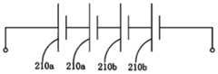
- Fig. 14is a circuit diagram in which each cell in Fig. 3 is connected in series;
- Fig. 15is a partial enlarged schematic diagram at D in Fig. 3;
- Fig. 16is the partial enlarged schematic diagram at E in Fig. 4;
- FIG. 17is a perspective view of a battery according to another embodiment of the present application in one direction;
- FIG. 18is an exploded schematic view of the battery in FIG. 17 in one direction;
- FIG. 19is a perspective view of a battery according to another embodiment of the present application in one direction;
- FIG. 20is an exploded schematic view of the battery in FIG. 19 in one direction;
- FIG. 21is a schematic diagram of an electrical device provided by an embodiment of the present application.
- the "installation”includes welding, screwing, snapping, gluing, etc. to fix or restrict a certain element or device to a specific position or place, and the element or device can be held in a specific position or place. It can also move within a limited range without moving, and the element or device can be disassembled or not disassembled after being fixed or restricted in a specific position or place, which is not limited in the embodiments of the present application.
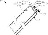
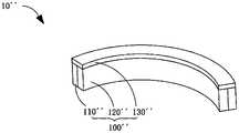
- FIGS. 1 to 5respectively show a perspective view of a battery 10 in two directions, an exploded schematic view of the battery 10 in two directions, and a projection view in one direction provided by one of the embodiments of the present application.
- 10(hereinafter referred to as battery) includes a housing case 100 , a battery pack 200 and a circuit board 300 .
- the housing case 100is a mounting structure for the battery pack 200 and the circuit board 300 , and extends in a curved shape.
- the battery pack 200is accommodated in the accommodating case 100 and includes a plurality of battery cells 210 .
- the circuit board 300is also accommodated in the accommodating case 100 , and the battery cells 210 are connected to the circuit board 300 .
- the "several" mentioned in this applicationmeans: one or more than two integers.
- the housing case 100includes a first part 110, a second part 120 and a third part 130 connected in sequence; the first part 110 is relative to the second part 120 as shown in the figure ( Fig. 5) is inclined downward, and there is an included angle ⁇ 1 therebetween, the third part 130 is inclined downward relative to the second part 120 as shown in the figure (Fig. 5), and there is a sandwich between the two
- the angle ⁇ 2is such that the first part 110 , the second part 120 and the third part 130 together form the recess 101 .
- the side of the receiving shell 100 facing the concave portion 101is the concave side
- the side of the receiving shell 100 facing away from the concave portion 101is the convex side, that is, the concave side of the receiving shell 100 and the convex side.
- the angle ⁇ 1 between the first portion 110 and the second portion 120is between 110° and 170°
- the angle ⁇ 2 between the third portion 130 and the second portion 120is between 110° and 170°.
- the housing case 100includes a first housing 140 and a second housing 150 disposed opposite to each other, and the first housing 140 and the second housing 150 are oppositely spliced to form a housing housing 100.
- the first casing 140includes a first lower casing 141 , a second lower casing 142 and a third lower casing 143 .
- the first lower shell portion 141is connected to one end of the second lower shell portion 142, and the third lower shell portion 143 is connected to the other end of the second lower shell portion 142; wherein, the first lower shell portion 141 is opposite to the second lower shell portion 142 is inclined downward as shown in the figure ( FIG.
- the third lower shell part 143is inclined downward relative to the second lower shell part 142 as shown in the figure ( FIG. 5 ).
- the first lower shell portion 141 , the second lower shell portion 142 and the third lower shell portion 143respectively form the recessed portion 101 on one side away from the second shell 150 ; the first lower shell portion 141 , the second lower shell portion 143 142 and the third lower shell portion 143 are respectively concave on one side facing the second shell 150 to form the first concave portion 102 .
- the second casing 150is disposed away from the above-mentioned recessed portion 101 , and includes a first upper casing portion 151 , a second upper casing portion 152 and a third upper casing portion 153 .
- the first upper shell part 151is connected with one end of the second upper shell part 152, and the third upper shell part 153 is connected with the other end of the second upper shell part 152; wherein, the first upper shell part 151 is opposite to the second upper shell part 152 is inclined downward as shown in the figure ( FIG. 5 ), and the third upper shell part 153 is inclined downward relative to the second upper shell part 152 as shown in the figure ( FIG. 5 ).
- the first upper shell portion 151 and the first lower shell portion 141are oppositely disposed and correspondingly spliced to form the first portion 110 ; the second upper shell portion 152 and the second lower shell portion 142 are disposed opposite and correspondingly spliced to form the above-mentioned first portion 110 .
- the second part 120 ; the third upper shell part 153 and the third lower shell part 143are disposed opposite to each other and spliced correspondingly to form the third part 130 .
- FIG. 6 and FIG. 7respectively show a perspective view of the battery 10 cut in one direction at the first part and a partial enlarged view at A, the first case 140 faces the second case.
- One side of the 150is provided with a positioning protrusion 1401, the positioning protrusion 1401 extends in a ring shape along the edge of the side of the first shell 140 facing the second shell 150; correspondingly, the second shell 150 faces the first shell 140
- the sides of the first upper shell portion 151 , the second upper shell portion 152 and the third upper shell portion 153 facing the first shell 140are concave inward to form a second recessed portion 103 , the second recessed portion 103 is the same as the above-mentioned first shell portion 103
- the concave portions 102together constitute a receiving cavity of the receiving shell 100 .
- the second upper shell portion 152extends in a curved shape, so as to better fit the battery compartment with an arc-shaped inner wall.
- a part of the structure of the second upper shell part 152extends in an arc shape, for example, the part of the second upper shell part 152 connected to the first upper shell part 151 extends in an arc shape; for example, the second upper shell part 152
- the portion connecting the third upper case portion 153extends in an arc shape.
- the accommodating case 100further includes a first extension portion 111 disposed at the connection between the first portion 110 and the second portion 120 facing the recessed portion 101 , and the first extension portion 111 simultaneously connects the first portion 110 and the second portion 120 , so as to strengthen the connection strength between the first part 110 and the second part 120 .
- the number of the first extending portions 111is plural, and the plural first extending portions 111 are arranged at intervals along the extending direction of the edge where the first portion 110 and the second portion 120 are connected.
- the housing case 100further includes a second extension part 121 , and the second extension part 121 is disposed on the second part 120 and the third part 130 facing the above-mentioned second part 120 .
- the connection point on one side of the concave portion 101is connected to the second part 120 and the third part 130 at the same time.
- the number of the second extending portions 121is plural, and the plural second extending portions 121 are arranged at intervals along the extending direction of the edge where the second portion 120 and the third portion 130 are connected.
- the battery pack 200includes a plurality of cells 210, and the plurality of cells 210 specifically includes a first battery cell 210a and a second battery cell 210b.
- the first cell 210 ais disposed in the first part 110
- the second cell 210 bis disposed in the third part 130 .
- the circuit board 300is disposed on the second part 120 , that is, it is located between the first cell 210 a and the second cell 210 b , so that each cell 210 is electrically connected to the circuit board 300 respectively.
- the first cell is located in the first partdoes not mean that all the first cells are located in the first part in an absolute sense, but means that most of the volume of the first cell is located in the first part , for example, the end of the first cell close to the circuit board can extend into the second part in a small amount; for the same reason, "the second cell is located in the third part” does not mean that all the second cells are located in the third part in an absolute sense. It means that most of the volume of the second cell is located in the third part, for example, the end of the second cell close to the circuit board may protrude into the second part in a small amount.
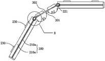
- FIG. 8 to FIG. 10respectively show a three-dimensional schematic diagram of the first battery cell, a schematic diagram of the expanded first battery cell, and a schematic diagram in one direction when the battery cell group 200 is connected to the circuit board 300 .
- the above-mentioned first cell 210 aincludes a first cell body 211 and a first tab 212 .
- the first cell main body 211is roughly in the shape of a square, which is inclined relative to the circuit board 300 and forms an obtuse angle ⁇ 1 therebetween; in this embodiment, the space between the first cell main body 211 and the above-mentioned circuit board 300
- the included angle ⁇ 1is between 110° and 170°, so as to match the included angle between the second part 120 and the first part 110 (or the third part 130 ).
- the first cell body 211specifically includes a first package 2111 , a first electrode assembly 2112 accommodated in the first package 2111 , and structures such as an electrolyte filled in the first package 2111 .
- the first package 2111includes a first body portion 21111 and a first package portion 21112 extending from an end of the first body portion 21111 close to the circuit board 300 .
- the first main body portion 21111is provided with an accommodation space for accommodating the first electrode assembly 2112 and the electrolyte solution; the first encapsulation portion 21112 is formed by thermal pressing, gluing, etc. after the first electrode assembly 2112 is accommodated in the first encapsulating member 2111 . Process to seal the part, so as to realize the encapsulation of the internal structure of the first package 2111 .
- the first encapsulation part 21112includes a first main encapsulation part 21113 and two first sub-encapsulation parts 21114 .
- the first main packaging part 21113is formed to extend from the end of the first main body part 21111 close to the circuit board 300 to the end away from the first main body part 21111 ; the first sub packaging part 21114 is provided on the first main packaging part 21113 away from the first On one side of the main body portion 21111 , the two first sub-package portions 21114 are arranged at intervals along the axis direction around which the receiving case 100 is bent and extended.
- first tab 212extends into the first package 2111 and is connected to the first electrode assembly 2112 , and the other end extends out of the first cell body 211 from the first package 21112 and extends out of the first battery.
- One end of the core body 211is electrically connected to the above-mentioned circuit board 300 .
- the first tab 212includes a first connecting portion 2121 and a second connecting portion 2122 that are connected to each other.
- the first connection portion 2121is connected to the first cell main body 211, and specifically extends from the first sub-package portion 21114 to the first cell main body 211; the second connection portion 2122 is bent relative to the first connection portion 2121, and connected to the above-mentioned circuit board 300 .
- the second cell 210bincludes a second cell main body and a second tab extending out of the second cell main body, the second cell main body is inclined relative to the circuit board 300, and an obtuse angle ⁇ 2 is formed therebetween;
- the diode tabsare electrically connected to the circuit board 300 .
- the battery cell set 200includes The two first cells 210a are directed along the side of the housing case 100 away from the recess 101 toward the side of the housing case 100 facing the recess 101 (for the convenience of description, it is defined as a preset direction hereinafter), the two first cells 210a. 210a is arranged in layers.
- the circuit board 300has a first side surface 301 and a second side surface 302 arranged opposite to each other along the predetermined direction; Among the two stacked first cells 210a, the first tab 212 of one of the first cells 210 is welded to the first side 301, and the first tab 212 of the other first cell 210a is welded to the second side 302.
- the first connecting portion 2121 of the first cell close to the recessed portion 101is straight.
- the first connecting portion 2121 of the first cell 210 facing away from the recessed portion 101is bent and includes a first section 21211 and a second Two sections 21212, one end of the first section 21211 is connected to the first cell body, the other end is connected to the second section 21212, one end of the second section 21212 away from the first section 21211 is connected to the second connecting portion 2122 Connection; the second section 21212 is inclined relative to the first section 21211, and the second connecting portion 2122 is inclined relative to the second section 21212.
- the first tab 212is fixed to the circuit board 300 by welding; it can be understood that, in other embodiments of the present application, the first tab 212 can also be fixed to the circuit board 300 by other means, such as snap connection , screw connection, etc.
- the above-mentioned cell group 200includes two second cells 210b, and the two second cells 210b are stacked along the predetermined direction.
- the second tab of a second cell 210bis connected to the first side surface 301
- the second tab of the other second cell 210bis connected to the second side surface 302 .
- the second tabis fixed to the circuit board 300 by welding; it can be understood that, in other embodiments of the present application, the second tab can also be fixed to the circuit board 300 by other means, such as snap connection, screw connection wait.
- the specific arrangement of the two second batteries 210bis the same as the arrangement of the above-mentioned two first batteries 210a, and reference may be made to the above description, which will not be repeated here.
- the two stacked first cells 210aare connected in series, the two stacked second cells 210b are connected in series, and the integral modules of the two first cells 210a and the integral modules of the two second cells 210b are connected in series , that is, two first cells and two second cells are connected in series in sequence, so that the cell group 200 can achieve a higher output voltage.
- conductive linesmay be provided on the circuit board 300 to realize the series connection between the cells. More specifically, please refer to FIG. 14 , which shows a circuit diagram in which each cell is connected in series in sequence, and in conjunction with FIG. 3 and FIG.
- the positive tab of the cell 210ais electrically connected; the negative tab of the first cell 210a facing the recess 101 is electrically connected with the positive tab of the second cell 210b facing the recess 101; the negative tab of the second cell 210b facing the recess 101 is electrically connected It is electrically connected to the positive tab of the second cell 210b facing away from the recess 101 .
- other connection modessuch as parallel connection or mixed connection, may also be used between the battery cells 210 .
- the circuit board 300is the control module of the battery 10. On the one hand, it is used to provide a series or parallel connection circuit for each battery cell 210. Charge and discharge, short circuit protection for the battery and other functions. In some embodiments, the end portion of the circuit board 300 close to the first cell 210a is disposed between the first encapsulation portions 21112 of the adjacent first cell 210a.
- the end of the circuit board 300 close to the first cell 210aprotrudes between the first sub-package parts 21114 of the two adjacent first cells 210a; in this way, the end of the circuit board 300 can be To a certain extent, risks such as short circuit caused by physical contact between the first tabs 212 of the above-mentioned two adjacent first cells due to the deformation of the first tabs 212 are reduced.
- the first encapsulation part 21112may only include the first main encapsulation part, then at this time, the end of the circuit board 300 close to the first cell 210a extends into two adjacent second between the first main packaging parts 21113 of a cell 210a.
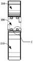
- FIG. 11 and FIG. 13are a schematic diagram viewed along the stacking direction of the first battery cells 210 a and an enlarged schematic view at C, respectively.
- the first The first connection portion 2121 of the cell 210ais located on the circuit board 300; in this way, the edge of the circuit board 300 completely extends beyond the root of the exposed portion of the first tab 212, so the circuit board 300 can well separate two adjacent first cells The first tab 212 of 210a.
- the end portion of the circuit board 300 close to the second cell 210bis disposed between the second encapsulation portions of the adjacent second cell 210b.
- the end of the circuit board 300 close to the second cell 210bprotrudes between the second sub-packages of two adjacent second cells 210b; in this way, the end of the circuit board 300 can reduce the risk of damage to a certain extent.
- the deformation of the second tabscauses the risk of short circuit and the like caused by physical contact between the second tabs of the two adjacent second cells 210 .
- the second encapsulation partmay only include the second main encapsulation part, then at this time, the end of the circuit board 300 close to the second cell 210b extends into two adjacent second between the second main packaging parts of the battery cells 210b.
- the second tabs of the second cells 210bare located on the circuit board 300; in this way, the edge of the circuit board 300 completely protrudes beyond the root of the outer portion of the second tabs exposed , so the circuit board 300 can well separate the second tabs of the two adjacent second cells 210b.
- the cell set 200further includes a first structural member 220 , the first structural member 220 is disposed between the first encapsulation portions 21112 of the two first cells 210 a , and the circuit board 300 is close to the first structural member 220 .
- An end of a cell 210 ais connected to the first structural member 220 .
- the side of the first structural member 220 facing the first tab 212 and the side facing the circuit board 300respectively include insulating materials, so as to avoid electrical contact between the first tabs 212 of the two stacked first cells 210a.
- the disposition of the first structure member 220can form a support for the two first encapsulation portions 21112 and reduce the collapse of the first encapsulation portion 21112 toward the center of the two first encapsulation portions 21112
- the first structural member 220is connected to the circuit board 300, so the first structural member 220 can form a support for the circuit board 300, thereby reducing the circuit board 300 facing the first cell 210a when the battery 10 is impacted
- the first structural member 220 and the circuit board 300together form a structure for separating the first tabs 212 of the two first batteries 210a, so as to further Risks such as short circuit caused by physical contact between the first tabs 212 of the two stacked first cells 210a are reduced.
- the first structural member 220includes foam, the foam abuts against the end of the circuit board 300 close to the battery core 210; the foam has a certain elasticity, which is conducive to the installation of the circuit board 300 on the one hand, and the other hand.
- the first structural member 220may also include other insulating elements such as rubber and silicone.
- the battery pack 200further includes a second structural member 221, the second structural member 221 is disposed between the second encapsulation parts of the two second batteries 210b, and the circuit board 300 is close to the end of the second battery 210b connected to the second structural member 221 .
- the side of the second structure member 221 facing the second tabs and the side facing the circuit board 300respectively include insulating materials, so as to avoid electrical contact between the second tabs of the two second battery cells 210b stacked on top of each other.
- the disposition of the second structure member 221can form a support for the two second encapsulation parts, and reduce the hidden danger of the second encapsulation part collapsing toward the center of the two second encapsulation parts;
- the second structural member 221is connected to the circuit board 300 , so the second structural member 221 can form a support for the circuit board 300 , thereby reducing the impact of the battery 10 , the circuit board 300 moving toward the second cell 210 b and causing the first
- the second structural member 221 and the circuit board 300together form a structure that separates the second tabs of the two second batteries 210b, so as to further reduce the number of stacked two batteries 210b.
- the second structural member 221includes foam, the foam abuts against the end of the circuit board 300 close to the second cell 210b; the foam has a certain elasticity, which is beneficial to the installation of the circuit board 300 on the one hand, On the other hand, when the circuit board 300 is displaced, a buffering effect can be formed on the circuit board 300 .
- the second structural member 221may also include other insulating elements such as rubber and silicone.
- the above-mentioned first cell body 211includes a first surface 201 and a second surface 202 oppositely disposed along the stacking direction of the first cell 210a, adjacent to the first cell 210a
- the first surfaces 201 of the 201are disposed adjacent to each other.
- the distance between the first encapsulation part 21112 and the first surface 201is greater than the distance between the first encapsulation part 21112 and the second surface 202; the design aims to increase the distance between the first encapsulation parts 21112 on the two first cells 210a The distance is to increase the distance between the first tabs 212 on the different first cells 210a, so as to reduce the hidden danger of the contact between the first tabs 212 on the different first cells 210a, and at the same time facilitate the extension of the end of the circuit board 300. into between the first packaging parts 21112 of the two first cells 210 .
- the second surface 202 of one of the first cells 210ais in contact with the housing case 100, so as to improve the heat dissipation effect of the cell group 200;
- An elastic member 230is embedded between the second surface 202 and the accommodating case 100 to reduce the impact force between the battery cell 210 and the accommodating case 100 when the battery cell 210 moves relative to the accommodating case 100 .
- the elastic member 230includes foam; of course, in other embodiments of the present application, the elastic member 230 may also be other elastic elements such as rubber and high-elasticity sponge.
- the second surfaces 202 of the two battery cells 210may both be in contact with the housing case 100 , or the second surface 202 of the two battery cells 210 may be in contact with the housing case 100 .
- An elastic member 230is disposed between the surface 202 and the receiving case 100 .
- the above-mentioned second cell bodyincludes a third surface and a fourth surface disposed opposite to each other along the stacking direction of the second cell 210b, and the third surface 201 adjacent to the second cell 210b is disposed adjacent to each other.
- the distance between the second encapsulation part and the third surfaceis greater than the distance between the second encapsulation part and the fourth surface; the design aims to increase the distance between the second encapsulation parts on the two second cells 210b, that is, increase The distance between the second tabs on the second cells 210b is greatly different, so as to reduce the hidden danger of contact between the second tabs on the different second cells 210b, and at the same time, it is convenient for the end of the circuit board 300 to protrude into the two second cells 210b between the second package parts.
- the fourth surface of one second battery cell 210bis in contact with the receiving case 100, so as to improve the heat dissipation effect of the battery cell group 200;
- the elastic members 230are embedded between the four surfaces and the accommodating case 100 to reduce the impact force between the second battery cell 210b and the accommodating case 100 when the second battery cell 210b moves relative to the accommodating case 100 .
- the fourth surfaces of the two second battery cells 210bmay both be in contact with the receiving case 100, or the two second battery cells 210b may be in contact with the receiving case 100.
- An elastic member 230is disposed between the fourth surface of the battery cell 210b and the receiving case 100 .
- the battery cell 210 described in this applicationincludes a soft-wrapped battery cell, but in other embodiments of the present application, the battery cell 210 may also be a steel-shell battery cell, and the specific type thereof is not described here. limited.
- the first surface 201 and the second surface 202 of the first battery cell 210aare both flat board structures.
- the opposite wall surface of 202is also a plane structure, so that the first battery cell 210a can be fitted and fitted with the inner wall of the receiving case 100 when installed in the receiving case 100 .
- the third surface and the fourth surface of the second battery cell 210bare both flat board structures.
- the walls of the first housing and the second housing respectively opposite to the fourth surfaceare also planar structures. Therefore, it can be ensured that when the second battery cell 210b is installed in the accommodating case 100 , it can fit and fit with the inner wall of the accommodating case 100 .
- FIG. 15 and FIG. 16respectively show the partially enlarged schematic diagram at D in FIG. 3 and the partially enlarged schematic diagram at E in FIG. 4 , and in combination with other drawings, the circuit board 300 is accommodated in the above-mentioned second part 120, the inner wall of the first housing 140 is provided with a support portion 144, and the circuit board 300 is mounted on the support portion 144; at the same time, a side of the circuit board 300 away from the support portion 144 and the second housing 150 are embedded with The elastic buffer member 310 ( FIG. 3 ) enables the circuit board 300 to be stably mounted on the receiving case 100 .
- a protruding portion 154extends from the inner wall of the second housing 150 at a position corresponding to the circuit board 300 .
- One end of the protruding portion 154 facing the circuit board 300is provided with a groove 104 , and one end of the buffer member 310 abuts against the The other end of the circuit board 300 extends into the groove 104 , that is, the buffer member 310 is at least partially disposed in the groove 104 .
- the buffer member 310includes foam; it can be understood that, in other embodiments of the present application, the buffer member 310 may also be other elastic elements such as rubber and high-elasticity sponge.
- the inner wall of the second housing 150extends in the groove 104 to form an abutting portion 155 , and the side of the abutting portion 155 facing the circuit board 300 is parallel to the second side surface 302 , so that the buffer member 310 can be It is only necessary to set it in a simple block shape, and it is not necessary to make the end of the buffer member 310 away from the circuit board 300 to match the shape of the second housing 150 .
- the support portion 144is provided with a positioning column 145 extending toward the circuit board 300 , and the circuit board 300 is provided with a positioning hole adapted to the positioning column 145 . 303 ; the positioning post 145 is inserted into the positioning hole 303 to complete the positioning of the circuit board 300 and the first housing 140 , thereby facilitating the assembly of the circuit board 300 .
- the circuit board 300may also be provided with a positioning post, and the protruding portion 144 is provided with a suitable positioning hole, and the positioning post and the positioning hole cooperate together to assist the circuit Installation of the board 300.
- the battery 10 provided in this embodiment of the present applicationincludes a housing case 100 , a battery cell group 200 and a circuit board 300 .
- the accommodating case 100extends in a curved shape, so that the accommodating case 100 has a convex side and a concave side.
- the battery pack 200is accommodated in the accommodating case 100 and includes a plurality of battery cells 210 .
- the circuit board 300is also accommodated in the accommodating case 100 , and the above-mentioned battery cells 210 are electrically connected to the circuit board 300 .
- the battery 10 provided in the embodiment of the present applicationhas a curved and extended shape, so it can be adapted to a curved battery compartment in an electrical device.
- the present applicationalso provides another battery 10 ′, please refer to FIG. 17 and FIG. 18 , which show a three-dimensional schematic view and an exploded schematic view of the battery 10 ′, respectively.
- the battery 10 ′(hereinafter referred to as the battery),
- the battery 10'includes a housing case 100', a battery pack 200' and a circuit board 300'.
- the accommodating case 100 ′is a mounting structure for the battery pack 200 ′ and the circuit board 300 ′, which extends in a curved shape, so that the accommodating case 100 ′ has a convex side and a concave side.
- the battery pack 200'is accommodated in the housing case 100', and includes a plurality of battery cells 210'.
- the circuit board 300'is also accommodated in the accommodating case 100', and the above-mentioned battery cells 210' are connected to the circuit board 300'.
- the receiving case 100 ′extends in an arc shape as a whole, so that the receiving case 100 ′ has a concave side and a convex side.
- the receiving case 100'includes a first casing 110' and a second casing 120'.
- the first casing 110'includes a bottom wall 111' extending in an arc shape, and a side wall 112' vertically extending from the edge of the bottom wall 111';
- the second casing 120'is fixed to the side wall 112' and faces away from One side of the bottom wall 111' and block the end of the side wall 112' facing away from the bottom wall 111'.
- the bottom wall 111 ′ and the side wall 112 ′are integrally formed; it can be understood that in other embodiments of the present application, the bottom wall 111 ′ and the side wall 112 ′ can also be formed separately, and then fixed by Components are fixedly connected.
- the circuit board 300 ′is disposed opposite to the second casing 120 ′, and is bent and extended along the direction in which the receiving casing 100 ′ is bent and extended.
- the battery pack 200 ′includes a plurality of battery cells 210 ′, the plurality of battery cells 210 ′ are arranged at intervals along the bending and extending direction of the circuit board 300 ′, and each battery cell 210 ′ is electrically connected to the circuit board 300 ′.
- the cell 210 ′includes a cylindrical cell, and the axial direction of the cylindrical cell is parallel to the axial direction around which the arc-shaped extension of the receiving shell 100 ′ surrounds.
- the battery 10 ′ provided in the embodiment of the present applicationalso has a curved and extended shape, so it can be adapted to a curved battery compartment in an electrical device.
- the present applicationalso provides another battery 10 ′′, please refer to FIG. 19 and FIG. 20 , which show a three-dimensional schematic view and an exploded schematic view of the battery 10 ′′, respectively.
- the battery 10 ′′(hereinafter referred to as the battery) includes The housing case 100", the battery cell group 200" and the circuit board 300" are accommodated.
- the accommodating case 100''is a mounting structure for the battery pack 200'' and the circuit board 300'', which extends in a curved shape, so that the accommodating case 100'' has a convex side and a concave side.
- the battery pack 200"is accommodated in the accommodating case 100", which includes a plurality of battery cells 210".
- the circuit board 300"is also accommodated in the accommodating case 100", and the above-mentioned battery cells 210" are connected to the circuit board 300".
- the housing case 100 ′′includes a rear housing 110 ′′, a front housing 120 ′′, and a second housing 130 ′′.
- One sideis concave to form a first accommodating cavity extending in an arc shape, and the first accommodating cavity is used for accommodating the battery pack 200.
- the second shell 130"is fixed to the rear shell One end of the body 110'' and cover the rear casing 110'' and the front casing 120'' as a whole; the side of the second casing 130 facing the rear casing 110'' is concave to form a second accommodating cavity extending in an arc shape.
- the two accommodating cavitiesare used for accommodating the circuit board 300".
- the arc-shaped extending direction of the above-mentioned first accommodating cavity and the second accommodating cavityis the same as the arc-shaped extending direction of the rear casing 110 ′′.
- the battery cell group 200"includes a plurality of battery cells 210", the plurality of battery cells 210" are arranged at intervals along the bending and extending direction of the circuit board 300", and each battery cell 210" is electrically connected to the circuit board 300".
- the battery cell 210 ′′includes a cylindrical battery core; the difference from the previous embodiment is that in this embodiment, the axis direction of the cylindrical battery core is perpendicular to the axis direction surrounded by the arc-shaped extension of the above-mentioned housing shell 100 ′′.
- the battery cells 210 in the battery cell group 200"are connected in an arc shape at the end.
- the battery 10"includes two battery cell groups 200", and the two battery cell groups 200" extend in an arc shape along the receiving shell 100". The surrounding axis directions are spaced apart.
- the battery 10 ′′ provided in the embodiment of the present applicationalso has a curved and extended shape, so it can be adapted to a curved battery compartment in an electrical device.
- the present applicationalso provides an electrical device.
- the electrical equipment 1includes a bracket 20 and a battery in any of the above-mentioned embodiments, and the battery is installed on the above-mentioned bracket 20 .
- the electrical equipment 1includes a circular cleaning robot, and the cleaning robot includes the above-mentioned bracket 20 and the above-mentioned battery.
- the cleaning robot including the above-mentioned battery 10is explained; it can be understood that, in other embodiments of the present application, the electrical equipment 1 may also be other electrical equipment such as an electric vehicle and an electric rice cooker.
- the electrical device 1includes a bracket 20 , a battery 10 and other devices, such as a motor, a fan, and the like.
- the bracket 20has a cylindrical shape as a whole, and an accommodating cavity 21 is provided inside the bracket 20 for accommodating the battery 10 and the above-mentioned devices such as the motor.
- the accommodating cavity 21specifically includes a cylindrical first accommodating space 21a formed by expanding outward from the axis of the accommodating cavity 21, and an annular second accommodating space 21b surrounding the periphery of the first accommodating space 21a.
- the second accommodating space 21bis located between the first accommodating space 21a and the inner wall of the accommodating cavity 21 .
- the second accommodating space 21bincludes a curved battery compartment area for accommodating the battery 10, and the battery 10 is arranged in the above-mentioned battery compartment area.
- the accommodating case 100 of the battery 10is bent and extended to form a concave side and an outer convex side.
- the concave side of the accommodating case 100is disposed toward the center of the accommodating cavity 21 , and the accommodating case 100 is convex.
- One side of the deviceis set close to or attached to the inner wall of the accommodating cavity 21 .
- the cleaning robots currently on the marketall the devices including the battery in the accommodating cavity are centrally arranged in the above-mentioned first accommodating space, and the setting of the second accommodating space aims to avoid the contour of the peripheral devices and the first accommodating space.
- the inner wall of 21ainterferes, but it makes it difficult to use the second accommodating space, that is, the space utilization rate of the cleaning robot is low, and it is difficult to realize a miniaturized design.
- the battery 10 in this embodimentcan make good use of the annular second accommodating space 21b in the upper electrical equipment 1, thereby effectively reducing the volume of the first accommodating space 21a, thereby reducing the overall volume of the cleaning robot , which is conducive to the realization of the miniaturized design of cleaning robots.
- the volume of the battery 10should be the largest, that is, the volume of the first part 110 , the second part 120 and the third part 130 should be made as large as possible.
- the maximum determination methodis illustrated as an example, as follows:
- the first part 110extends straight.
- the width of the first part 110 on the cross sectionis defined as the width T
- the length of the first part 110 on the cross sectionis defined as the length L
- the cross-sectional area of the first part 110 perpendicular to the axis of the accommodating cavity 21is defined as Positioned as area S, the applicant can get the following formula:
- the applicantcan determine that when hour, , the area S is the largest.
- the method for determining the largest volume of the third part 130 and the second part 110is substantially the same, and details are not described here.
- the battery 10 of the electrical device 1 provided in the embodiment of the present applicationis in a curved and extended shape, so the battery 10 can be adapted to the curved battery compartment in the electrical device 1, and the space utilization rate of the electrical device 1 is high.
Landscapes
- Chemical & Material Sciences (AREA)
- Chemical Kinetics & Catalysis (AREA)
- Electrochemistry (AREA)
- General Chemical & Material Sciences (AREA)
- Battery Mounting, Suspending (AREA)
Abstract
Description
Translated fromChinese相关申请的交叉引用CROSS-REFERENCE TO RELATED APPLICATIONS
本申请要求2021年03月05日向中国国家知识产权局递交的申请号为202120487486.1,名称为“电池与用电设备”的在先申请的优先权,上述在先申请的内容以引入的方式并入本文本中。This application claims the priority of an earlier application entitled "Battery and Electrical Equipment" with application number 202120487486.1 filed with the State Intellectual Property Office of China on March 5, 2021, the contents of the aforementioned earlier application are incorporated by reference in this text.
本申请实施例涉及电池技术领域,尤其涉及一种电池与用电设备。The embodiments of the present application relate to the technical field of batteries, and in particular, to a battery and electrical equipment.
电池是一种将外界的能量转化为电能并储存于其内部,以在需要的时刻对外部用电设备(如便携式电子设备)进行供电的装置。目前,电池广泛地运用于手机、平板、笔记本电脑等用电设备中。A battery is a device that converts external energy into electrical energy and stores it inside to power external electrical devices (such as portable electronic devices) when needed. At present, batteries are widely used in electric devices such as mobile phones, tablets, and notebook computers.
本申请的发明人在实现本申请的过程中发现:目前,市场上的电池多为方形,但有些用电设备因其内元器件的布局,而方便设置弯曲形状的电池仓,因此有必要设计一种适配弯曲形状电池仓的电池。In the process of realizing the present application, the inventor of the present application found that: at present, most of the batteries on the market are square, but some electrical equipment is convenient to set a curved battery compartment due to the layout of the internal components, so it is necessary to design A battery that fits into a curved battery compartment.
发明内容SUMMARY OF THE INVENTION
本申请实施例旨在提供一种电池与用电设备,以适配用电设备中弯曲形状的电池仓。The embodiments of the present application aim to provide a battery and an electrical device, so as to fit a battery compartment with a curved shape in the electrical device.
本申请实施例解决其技术问题采用以下技术方案:The embodiment of the present application adopts the following technical solutions to solve its technical problems:
一种电池,包括收容壳、电芯组与电路板。其中,所述收容壳呈弯曲状延伸,以使所述收容壳具有外凸的一侧以及内凹的一侧。电芯组收容于所述收容壳,所述电芯组包括若干个电芯。电路板收容于所述收容壳,所述电芯与所述电路板电连接。本申请实施例提供的电池呈弯曲延伸的形状,故其可以适配用电设备中弯曲形状的电池仓。A battery includes a housing case, a battery cell group and a circuit board. Wherein, the accommodating shell extends in a curved shape, so that the accommodating shell has a convex side and a concave side. The battery pack is accommodated in the housing case, and the battery pack includes a plurality of battery cells. The circuit board is accommodated in the accommodating case, and the battery core is electrically connected with the circuit board. The battery provided in the embodiment of the present application has a curved and extended shape, so it can be adapted to a curved battery compartment in an electrical device.
作为上述方案的进一步改进方案,所述收容壳包括依次连接的第一部分、第二部分以及第三部分;所述第一部分相对于第二部分倾斜设置,所述第三部分相对于第二部分倾斜设置,所述第一部分、所述第二部分以及所述第三部分 共同围合形成凹部。As a further improvement of the above solution, the containing shell includes a first part, a second part and a third part connected in sequence; the first part is inclined relative to the second part, and the third part is inclined relative to the second part It is provided that the first part, the second part and the third part together form a concave part.
作为上述方案的进一步改进方案,所述电路板收容于所述第二部分;所述电池包括两组电芯组,其中一组电芯组收容于所述第一部分,另一组电芯组收容于所述第三部分。该设置使得电路板位于两电芯组之间,以便于各电芯分别与电路板电连接。As a further improvement of the above solution, the circuit board is accommodated in the second part; the battery includes two groups of battery cells, one of which is accommodated in the first part, and the other group of cells is accommodated in the first part. in the third part. In this arrangement, the circuit board is located between the two battery cell groups, so that each battery cell is electrically connected to the circuit board respectively.
作为上述方案的进一步改进方案,所述电芯包括电芯主体和延伸出所述电芯主体的极耳,所述电芯主体相对所述电路板倾斜设置,所述极耳与所述电路板电连接。As a further improvement of the above solution, the cell includes a cell body and a tab extending out of the cell main body, the cell body is inclined relative to the circuit board, and the tab is connected to the circuit board. electrical connection.
作为上述方案的进一步改进方案,所述电芯主体与所述电路板之间的夹角介于110°~170°之间。As a further improvement of the above solution, the angle between the main body of the battery cell and the circuit board is between 110° and 170°.
作为上述方案的进一步改进方案,所述电芯组包括层叠设置的两个电芯。所述电路板包括相对设置的第一侧面和第二侧面,同一所述电芯组中,一所述电芯的极耳焊接于所述第一侧面,另一所述电芯的极耳焊接于第二侧面。如此设置有助于将同一电芯组内的不同电芯的极耳隔绝开,以降低不同电芯的极耳短路的风险。As a further improvement of the above solution, the battery cell group includes two battery cells arranged in layers. The circuit board includes a first side surface and a second side surface arranged oppositely. In the same battery cell group, the tabs of one of the battery cells are welded to the first side surface, and the tabs of the other battery core are welded to the first side surface. on the second side. This arrangement helps to isolate the tabs of different cells in the same cell group, so as to reduce the risk of short-circuiting of the tabs of different cells.
作为上述方案的进一步改进方案,同一所述电芯组中的两电芯之间串联,两所述电芯组之间串联。As a further improvement of the above solution, two cells in the same cell group are connected in series, and two cell groups are connected in series.
作为上述方案的进一步改进方案,所述电芯主体包括主体部以及自所述主体部靠近所述电路板的一端延伸形成的封装部,所述极耳自所述封装部伸出所述电芯主体。所述电路板靠近电芯的端部设于同一电芯组内相邻电芯的封装部之间,以便于将同一电芯组内的不同电芯的极耳隔绝开,以降低不同电芯的极耳短路的风险。As a further improvement of the above solution, the cell body includes a main body portion and an encapsulation portion extending from an end of the main body portion close to the circuit board, and the tabs extend out of the cell from the encapsulation portion main body. The end of the circuit board close to the cell is arranged between the encapsulation parts of adjacent cells in the same cell group, so as to isolate the tabs of different cells in the same cell group, so as to reduce the reduction of different cells. risk of short-circuiting the tabs.
作为上述方案的进一步改进方案,所述封装部包括第一封装部和两个第二封装部,所述第一封装部自所述主体部靠近所述电路板的一端延伸形成,所述第二封装部设于所述第一封装部背离所述主体部的一侧。所述电芯包括两个极耳,每一极耳分别对应一所述第二封装部,所述极耳自所述第二封装部延伸出电芯主体,所述电路板靠近电芯的端部设于同一电芯组内相邻电芯的第二封装部之间。As a further improvement of the above solution, the encapsulation part includes a first encapsulation part and two second encapsulation parts, the first encapsulation part is formed by extending from an end of the main body part close to the circuit board, the second encapsulation part is formed The encapsulation portion is disposed on a side of the first encapsulation portion away from the main body portion. The battery core includes two tabs, each of which corresponds to one of the second encapsulation parts, the tabs extend from the second encapsulation part and the main body of the battery core, and the circuit board is close to the end of the battery core The part is arranged between the second encapsulation parts of adjacent cells in the same cell group.
作为上述方案的进一步改进方案,所述电芯组还包括绝缘件。同一所述电芯组内,所述绝缘件设于两所述电芯的封装部之间,所述电路板靠近电芯的端 部连接于绝缘件。As a further improvement of the above solution, the battery pack further includes an insulating member. In the same cell group, the insulating member is arranged between the encapsulation parts of the two cells, and the end portion of the circuit board close to the cell is connected to the insulating member.
作为上述方案的进一步改进方案,所述极耳包括第一连接部与第二连接部,所述第一连接部与所述电芯主体连接,所述第二连接部焊接于所述电路板,所述第二连接部相对所述第一连接部弯折设置。As a further improvement of the above solution, the tab includes a first connection part and a second connection part, the first connection part is connected to the main body of the battery cell, and the second connection part is welded to the circuit board, The second connecting portion is bent relative to the first connecting portion.
作为上述方案的进一步改进方案,所述第一连接部包括第一区段和第二区段,所述第一区段、所述第二区段与所述第二连接部依次弯折连接。As a further improvement of the above solution, the first connecting portion includes a first section and a second section, and the first section, the second section and the second connecting section are connected by bending in sequence.
作为上述方案的进一步改进方案,同一组所述电芯组中,沿所述电芯的堆叠方向观察,所述电芯的第一连接部位于所述电路板。As a further improvement of the above solution, in the same group of the battery cells, when viewed along the stacking direction of the battery cells, the first connection portion of the battery cells is located on the circuit board.
作为上述方案的进一步改进方案,同一组所述电芯组中,所述电芯主体包括沿所述电芯的堆叠方向相对设置的第一表面和第二表面,相邻电芯的第一表面相邻设置。所述封装部与所述第一表面之间的距离大于所述封装部与所述第二表面之间的距离,所述电路板靠近所述电芯的端部设于同一电芯组相邻电芯的封装部之间。As a further improvement of the above solution, in the same battery cell group, the battery cell body includes a first surface and a second surface oppositely arranged along the stacking direction of the battery cells, and the first surface of the adjacent battery cells Adjacent settings. The distance between the encapsulation part and the first surface is greater than the distance between the encapsulation part and the second surface, and the end of the circuit board close to the cell is arranged adjacent to the same cell group between the encapsulation parts of the cells.
作为上述方案的进一步改进方案,同一所述电芯组中,至少一所述电芯的第二表面与所述收容壳接触;和/或,同一所述电芯组中,至少一所述电芯的第二表面与收容壳之间设有弹性件。As a further improvement of the above solution, in the same cell group, the second surface of at least one of the cells is in contact with the receiving shell; and/or, in the same cell group, at least one of the cells An elastic piece is arranged between the second surface of the core and the receiving shell.
作为上述方案的进一步改进方案,所述收容壳包括第一壳体以及与第一壳体固定的第二壳体,所述第一壳体设有支撑部,所述电路板安装于所述支撑部。As a further improvement of the above solution, the housing case includes a first housing and a second housing fixed with the first housing, the first housing is provided with a support portion, and the circuit board is mounted on the support department.
作为上述方案的进一步改进方案,所述支撑部与所述电路板中的一个设有定位柱,另一个设有与所述定位柱相适配的定位孔,所述定位柱插入所述定位孔。As a further improvement of the above solution, one of the support part and the circuit board is provided with a positioning column, and the other is provided with a positioning hole adapted to the positioning column, and the positioning column is inserted into the positioning hole .
作为上述方案的进一步改进方案,第二壳体的内壁于对应所述电路板的位置延伸出凸出部,所述凸出部面向所述电路板的一端设有凹槽。所述电池包括缓冲件,所述缓冲件设于所述电路板与所述上壳之间,所述,所述缓冲件至少部分设于凹槽。As a further improvement of the above solution, a protruding portion extends from the inner wall of the second housing at a position corresponding to the circuit board, and an end of the protruding portion facing the circuit board is provided with a groove. The battery includes a buffer member, the buffer member is arranged between the circuit board and the upper case, and the buffer member is at least partially arranged in the groove.
作为上述方案的进一步改进方案,所述电芯包括软包电芯或钢壳电芯。As a further improvement of the above solution, the battery cell includes a soft-wrapped battery cell or a steel-shell battery cell.
作为上述方案的进一步改进方案,所述电路板弯曲延伸,所述电路板弯曲延伸的方向与所述收容壳弯曲延伸的方向相同。所述电芯组包括多个电芯,各所述电芯沿所述电路板弯曲延伸的方向间隔排布,各所述电芯均与所述电路板电连接。As a further improvement of the above solution, the circuit board is bent and extended, and the direction in which the circuit board is bent and extended is the same as the direction in which the receiving shell is bent and extended. The battery cell group includes a plurality of battery cells, each of the battery cells is arranged at intervals along the direction in which the circuit board is bent and extended, and each of the battery cells is electrically connected to the circuit board.
作为上述方案的进一步改进方案,所述收容壳呈弧形延伸,所述电路板呈弧形延伸。As a further improvement of the above solution, the receiving shell extends in an arc shape, and the circuit board extends in an arc shape.
作为上述方案的进一步改进方案,所述电芯包括圆柱形电芯。所述电芯的轴线方向与所述收容壳弧形延伸所环绕的的轴线方向平行;或者,所述电芯的轴线方向与所述收容壳弧形延伸的轴线方向垂直。As a further improvement of the above solution, the battery cell includes a cylindrical battery cell. The axial direction of the electric core is parallel to the axial direction of the arc-shaped extension of the containing shell; or, the axial direction of the electric core is perpendicular to the axial direction of the arc-shaped extension of the containing shell.
本申请实施例解决其技术问题还采用以下技术方案:The embodiment of the present application also adopts the following technical solutions to solve its technical problems:
一种用电设备,包括支架与上述的电池,所述电池安装于所述支架。An electrical device includes a bracket and the above-mentioned battery, and the battery is mounted on the bracket.
作为上述方案的进一步改进方案,所述用电设备包括清洁机器人。所述清洁机器人包括所述支架,所述支架的内部设有容置腔。所述电池收容于所述容置腔,所述收容壳弯曲延伸,所述收容壳外凸的一侧靠近所述容置腔的内壁设置,所述收容壳内凹的一侧朝向所述容置腔的中心。As a further improvement of the above solution, the electrical equipment includes a cleaning robot. The cleaning robot includes the bracket, and the inner part of the bracket is provided with an accommodating cavity. The battery is accommodated in the accommodating cavity, the accommodating shell is bent and extended, the convex side of the accommodating shell is disposed close to the inner wall of the accommodating cavity, and the concave side of the accommodating shell faces the accommodating cavity. the center of the cavity.
本申请的有益效果是:The beneficial effects of this application are:
本申请实施例提供的电池包括收容壳、电芯组和电路板。其中,收容壳呈弯曲状延伸,以使收容壳具有外凸的一侧以及内凹的一侧。电芯组收容于收容壳,其包括若干个电芯。电路板亦收容于收容壳,上述电芯与该电路板电连接。The battery provided by the embodiment of the present application includes a housing case, a battery cell group, and a circuit board. Wherein, the accommodating shell extends in a curved shape, so that the accommodating shell has a convex side and a concave side. The battery core group is accommodated in the receiving case, and includes a plurality of battery cores. The circuit board is also accommodated in the accommodating case, and the electric core is electrically connected to the circuit board.
本申请实施例提供的电池呈弯曲延伸的形状,故其可以适配用电设备中弯曲形状的电池仓。The battery provided in the embodiment of the present application has a curved and extended shape, so it can be adapted to a curved battery compartment in an electrical device.
一个或多个实施例通过与之对应的附图进行示例性说明,这些示例性说明并不构成对实施例的限定,附图中具有相同参考数字标号的元件表示为类似的元件,除非有特别申明,附图中的图不构成比例限制。One or more embodiments are exemplified by the accompanying drawings, which are not intended to limit the embodiments, and elements with the same reference numerals in the drawings represent similar elements, unless otherwise specified. It is stated that the figures in the accompanying drawings do not constitute a scale limitation.
图1为本申请其中一实施例提供的电池的一个方向的立体示意图;FIG. 1 is a perspective schematic diagram of a battery provided in one embodiment of the present application in one direction;
图2为图1中电池的另一个方向的立体示意图;Fig. 2 is the perspective schematic diagram of another direction of the battery in Fig. 1;
图3为图1中电池的一个方向的分解示意图;Fig. 3 is the exploded schematic diagram of one direction of the battery in Fig. 1;
图4为图1中电池的另一个方向的分解示意图;Fig. 4 is the exploded schematic diagram of another direction of the battery in Fig. 1;
图5为图1中电池的一个方向的投影示意图;Fig. 5 is the projection schematic diagram of one direction of the battery in Fig. 1;
图6为图1中电池于第一部分处剖切后的一个方向的立体示意图;FIG. 6 is a perspective view of the battery in FIG. 1 in one direction after being cut at the first part;
图7为图6中A处的局部放大示意图;Fig. 7 is the partial enlarged schematic diagram of A place in Fig. 6;
图8为图3中第一电芯的立体示意图;FIG. 8 is a three-dimensional schematic diagram of the first battery cell in FIG. 3;
图9为图3中第一电芯展开后的示意图;Fig. 9 is the schematic diagram after the first cell in Fig. 3 is unfolded;
图10为电芯组与电路板之间的一个方向的连接示意图;FIG. 10 is a schematic diagram of the connection between the cell group and the circuit board in one direction;
图11为电芯组与电路板之间的另一个方向的连接示意图;FIG. 11 is a schematic diagram of the connection between the cell group and the circuit board in another direction;
图12为图10中B处的局部放大示意图;Fig. 12 is a partial enlarged schematic diagram at B in Fig. 10;
图13为图11中C处的局部放大示意图;Fig. 13 is a partial enlarged schematic diagram at C in Fig. 11;
图14为图3中各电芯依次串联的电路图;Fig. 14 is a circuit diagram in which each cell in Fig. 3 is connected in series;
图15为图3中D处的局部放大示意图;Fig. 15 is a partial enlarged schematic diagram at D in Fig. 3;
图16为图4中E处的局部放大示意图;Fig. 16 is the partial enlarged schematic diagram at E in Fig. 4;
图17为本申请其中另一实施例提供的电池的一个方向的立体示意图;FIG. 17 is a perspective view of a battery according to another embodiment of the present application in one direction;
图18为图17中电池的一个方向的分解示意图;FIG. 18 is an exploded schematic view of the battery in FIG. 17 in one direction;
图19为本申请其中又一实施例提供的电池的一个方向的立体示意图;FIG. 19 is a perspective view of a battery according to another embodiment of the present application in one direction;
图20为图19中电池的一个方向的分解示意图;FIG. 20 is an exploded schematic view of the battery in FIG. 19 in one direction;
图21为本申请其中一实施例提供的用电设备的示意图。FIG. 21 is a schematic diagram of an electrical device provided by an embodiment of the present application.
为了便于理解本申请,下面结合附图和具体实施例,对本申请进行更详细的说明。需要说明的是,当元件被表述“固定于”/“固接于”/“安装于”另一个元件,它可以直接在另一个元件上、或者其间可以存在一个或多个居中的元件。当一个元件被表述“连接”另一个元件,它可以是直接连接到另一个元件、或者其间可以存在一个或多个居中的元件。本说明书所使用的术语“垂直的”、“水平的”、“左”、“右”、“内”、“外”以及类似的表述只是为了说明的目的。In order to facilitate the understanding of the present application, the present application will be described in more detail below with reference to the accompanying drawings and specific embodiments. It should be noted that when an element is described as being "fixed to"/"fixed to"/"mounted to" another element, it can be directly on the other element, or there may be one or more intervening elements therebetween. When an element is referred to as being "connected" to another element, it can be directly connected to the other element or one or more intervening elements may be present therebetween. The terms "vertical", "horizontal", "left", "right", "inner", "outer" and similar expressions used in this specification are for illustrative purposes only.
除非另有定义,本说明书所使用的所有的技术和科学术语与属于本申请的技术领域的技术人员通常理解的含义相同。在本申请的说明书中所使用的术语只是为了描述具体的实施例的目的,不是用于限制本申请。本说明书所使用的术语“和/或”包括一个或多个相关的所列项目的任意的和所有的组合。Unless otherwise defined, all technical and scientific terms used in this specification have the same meaning as commonly understood by one of ordinary skill in the technical field belonging to this application. The terms used in the specification of the present application are only for the purpose of describing specific embodiments, and are not used to limit the present application. As used in this specification, the term "and/or" includes any and all combinations of one or more of the associated listed items.
此外,下面所描述的本申请不同实施例中所涉及的技术特征只要彼此之间未构成冲突就可以相互结合。In addition, the technical features involved in the different embodiments of the present application described below can be combined with each other as long as there is no conflict with each other.
在本说明书中,所述“安装”包括焊接、螺接、卡接、粘合等方式将某一元件或装置固定或限制于特定位置或地方,所述元件或装置可在特定位置或地 方保持不动也可在限定范围内活动,所述元件或装置固定或限制于特定位置或地方后可进行拆卸也可不能进行拆卸,在本申请实施例中不作限制。In this specification, the "installation" includes welding, screwing, snapping, gluing, etc. to fix or restrict a certain element or device to a specific position or place, and the element or device can be held in a specific position or place. It can also move within a limited range without moving, and the element or device can be disassembled or not disassembled after being fixed or restricted in a specific position or place, which is not limited in the embodiments of the present application.
请参阅图1至图5,其分别示出了本申请其中一实施例提供的电池10的两个方向的立体示意图、该电池10的两个方向的分解示意图以及一个方向的投影视图,该电池10(以下简称电池)包括收容壳100、电芯组200以及电路板300。其中,收容壳100是电芯组200以及电路板300的安装结构,其呈弯曲状延伸。电芯组200收容于收容壳100,其包括若干个电芯210。电路板300亦收容于收容壳100,上述电芯210与该电路板300连接。值得一提的是,本申请中所述的“若干”意为:一个或两个以上的整数。Please refer to FIGS. 1 to 5 , which respectively show a perspective view of a
对于上述收容壳100,请先参阅图1与图2,收容壳100包括依次连接的第一部分110、第二部分120以及第三部分130;该第一部分110相对于第二部分120如图示(图5)向下倾斜设置,且两者之间具有一夹角α1,该第三部分130相对于第二部分120如图示(图5)向下倾斜设置,且两者之间具有一夹角α2,如此使得第一部分110、第二部分120以及第三部分130共同围合形成凹部101。即是:收容壳100面向该凹部101的一侧为内凹的一侧,该收容壳100背向凹部101的一侧为外凸的一侧,亦即是收容壳100具有内凹的一侧以及外凸的一侧。其中,第一部分110与第二部分120之间的角度α1介于110°~170°之间,第三部分130与第二部分120之间的角度α2介于110°~170°之间。For the above-mentioned
请进一步参阅图3与图4,本实施例中,收容壳100包括相对设置的第一壳体140以及第二壳体150,该第一壳体140与第二壳体150相对拼接成收容壳100。同时结合5,第一壳体140包括第一下壳部141、第二下壳部142以及第三下壳部143。第一下壳部141与第二下壳部142的一端连接,第三下壳部143与第二下壳部142的另一端连接;其中,第一下壳部141相对于第二下壳部142如图示(图5)向下倾斜设置,第三下壳部143相对于第二下壳部142如图示(图5)向下倾斜设置。该第一下壳部141、第二下壳部142以及第三下壳部143各自背离第二壳体150的一侧共同形成上述凹部101;该第一下壳部141、第二下壳部142以及第三下壳部143各自面向第二壳体150的一侧内凹以形成第一凹陷部102。第二壳体150背离上述凹部101设置,其包括第一上壳部151、第二上壳部152以及第三上壳部153。第一上壳部151与第二上壳部152的一端连接,第三上壳部153与第二上壳部152的另一端连接;其中, 第一上壳部151相对于第二上壳部152如图示(图5)向下倾斜设置,第三上壳部153相对于第二上壳部152如图示(图5)向下倾斜设置。该第一上壳部151与上述第一下壳部141相对设置并对应拼接以形成上述第一部分110;该第二上壳部152与上述第二下壳部142相对设置并对应拼接以形成上述第二部分120;该第三上壳部153与上述第三下壳部143相对设置并对应拼接以形成上述第三部分130。具体地,请参阅图6与图7,其分别示出了该电池10于第一部分处剖切后的一个方向的立体示意图以及A处的局部放大示意图,第一壳体140面向第二壳体150的一侧设有定位凸起1401,该定位凸起1401沿第一壳体140面向第二壳体150的一面的边缘延伸呈环形;相应地,第二壳体150面向第一壳体140的一侧设有与该定位凸起1401相适配的定位凹槽1501,上述定位凸起1401插入该定位凹槽1501,以使第一壳体140与第二壳体150实现定位安装,进而便于两者通过粘接、螺接、卡接等固定方式固定连接。第一上壳部151、第二上壳部152以及第三上壳部153各自面向第一壳体140的一侧内凹以形成第二凹陷部103,该第二凹陷部103与上述第一凹陷部102共同组成收容壳100的收容腔。优选地,所述第二上壳部152呈弯曲形延伸,从而可较好地适配贴合于内壁呈圆弧形壁面的电池仓。优选地,所述第二上壳部152部分结构呈弧形延伸,比如所述第二上壳部152连接第一上壳部151的部分呈弧形延伸;比如所述第二上壳部152连接第三上壳部153的部分呈弧形延伸。Please further refer to FIG. 3 and FIG. 4 , in this embodiment, the
进一步地,收容壳100还包括设置于上述第一部分110与第二部分120面向凹部101一侧的连接处的第一延伸部111,该第一延伸部111同时连接第一部分110与第二部分120,从而强化第一部分110与第二部分120之间的连接强度。较优地,上述第一延伸部111的数量为复数个,该复数个第一延伸部111沿第一部分110与第二部分120连接处棱边延伸的方向间隔设置。同理,为强化第二部分120与第三部分130之间的连接强度,收容壳100还包括第二延伸部121,该第二延伸部121设置于上述第二部分120与第三部分130面向凹部101一侧的连接处,并同时连接第二部分120与第三部分130。较优地,上述第二延伸部121的数量为复数个,该复数个第二延伸部121沿第二部分120与第三部分130连接处棱边延伸的方向间隔设置。Further, the
对于上述电芯组200与电路板300,请先参阅图3与图4,该电芯组200包括若干个电芯210,该若干个电芯210具体包括第一电芯210a与第二电芯210b。 其中,第一电芯210a设于第一部分110,第二电芯210b设于第三部分130。电路板300设于上述第二部分120,即是其位于第一电芯210a与第二电芯210b之间,以便于各电芯210分别与电路板300电连接。当然,本实施例中所述的“第一电芯设于第一部分”并非绝对意义上的指第一电芯全部位于第一部分,而是指第一电芯的体积的绝大部分位于第一部分,例如,该第一电芯靠近电路板的一端可以少量地伸入第二部分;同理,“第二电芯设于第三部分”并非绝对意义上的指第二电芯全部位于第三部分,而是指第二电芯的体积的绝大部分位于第三部分,例如,该第二电芯靠近电路板的一端可以少量地伸入第二部分。For the above-mentioned
请具体参阅图8至图10,其分别示出了第一电芯的立体示意图、第一电芯展开后的示意图,以及,电芯组200与电路板300连接状态下的一个方向的示意图,同时结合其他附图,上述第一电芯210a包括第一电芯主体211和第一极耳212。其中,第一电芯主体211大致呈方块状,其相对于电路板300倾斜设置,两者之间构成一钝角β1;本实施例中,第一电芯主体211与上述电路板300之间的夹角β1介于110°~170°之间,从而与上述第二部分120、第一部分110(或第三部分130)之间的夹角相适配。第一电芯主体211具体包括第一封装件2111、收容于第一封装件2111内的第一电极组件2112,以及填充于第一封装件2111内的电解液等结构。第一封装件2111包括第一主体部21111以及自第一主体部21111靠近电路板300的一端延伸出的第一封装部21112。第一主体部21111设有用于收容上述第一电极组件2112与电解液的收容空间;第一封装部21112是上述第一电极组件2112收容于第一封装件2111后,通过热压、胶粘等工艺进行密封的部位,从而实现对第一封装件2111内部结构的封装。在一些实施例中,第一封装部21112包括第一主封装部21113和两个第一副封装部21114。具体地,第一主封装部21113自第一主体部21111靠近电路板300的一端向背离第一主体部21111的一端延伸形成;第一副封装部21114设于第一主封装部21113背离第一主体部21111的一侧,两第一副封装部21114沿收容壳100弯曲延伸所环绕的轴线方向间隔设置。值得一提的是,本申请文件中所述的“沿某部件弯曲延伸所环绕的轴线方向”具体意为:某部件弯曲延伸的轨迹所确定的平面的法线方向,其中所述的“弯曲延伸”可以是弧形延伸、S形延伸或其他非直线形状的延伸。Please refer to FIG. 8 to FIG. 10 , which respectively show a three-dimensional schematic diagram of the first battery cell, a schematic diagram of the expanded first battery cell, and a schematic diagram in one direction when the
第一极耳212的一端伸入第一封装件2111内,并与上述第一电极组件 2112连接,另一端自上述第一封装部21112延伸出第一电芯主体211,且延伸出第一电芯主体211的一端与上述电路板300电连接。具体地,第一极耳212包括彼此连接的第一连接部2121与第二连接部2122。该第一连接部2121与上述第一电芯主体211连接,其具体自上述第一副封装部21114伸出第一电芯主体211;第二连接部2122相对第一连接部2121弯折设置,并连接于上述电路板300。One end of the
同理,第二电芯210b包括第二电芯主体和延伸出第二电芯主体的第二极耳,第二电芯主体相对电路板300倾斜设置,两者之间构成一钝角β2;第二极耳与电路板300电连接。第二电芯210b的具体结构可参阅上述对第一电芯210a的说明,在此不赘述。Similarly, the
请参阅图10至图13,其分别示出了电芯组200与电路板300的两个方向的连接示意图,以及B处、C处的局部放大示意图,本实施例中,电芯组200包括两第一电芯210a,沿收容壳100背离凹部101的一侧指向收容壳100面向凹部101的一侧的方向(为方便说明,以下将其定义为预设方向),该两第一电芯210a层叠设置。相应地,电路板300具有沿上述预设方向相对设置的第一侧面301与第二侧面302;其中,第一侧面301靠近上述凹部101设置,第二侧面302背离上述凹部101设置。层叠设置的两第一电芯210a中,其中一第一电芯210的第一极耳212焊接于上述第一侧面301,另一第一电芯210a的第一极耳212焊接于第二侧面302。靠近上述凹部101的第一电芯的第一连接部2121呈平直状.背离上述凹部101的第一电芯210的第一连接部2121呈弯折状,其包括第一区段21211与第二区段21212,该第一区段21211的一端与第一电芯主体连接,另一端与第二区段21212连接,第二区段21212远离第一区段21211的一端与第二连接部2122连接;第二区段21212相对上述第一区段21211倾斜设置,第二连接部2122相对第二区段21212倾斜设置。可选地,第一极耳212通过焊接固定于电路板300;可以理解的是,在本申请的其他实施例中,第一极耳212还可以通过其他方式固定于电路板300,如卡接、螺接等。Please refer to FIG. 10 to FIG. 13 , which respectively show schematic diagrams of the connection between the battery cell set 200 and the
同理,上述电芯组200包括两第二电芯210b,沿上述预设方向,该两第二电芯210b层叠设置。其中,一第二电芯210b的第二极耳连接于上述第一侧面301,另一第二电芯210b的第二极耳连接于第二侧面302。可选地,第二极耳通过焊接固定于电路板300;可以理解的是,在本申请的其他实施例中,第二 极耳还可以通过其他方式固定于电路板300,如卡接、螺接等。两第二电芯210b的具体设置方式与上述两第一电芯210a的设置方式相同,可参见上述说明,在此不赘述。Similarly, the above-mentioned
层叠设置的两第一电芯210a之间串联,层叠设置的两第二电芯210b之间串联,且该两第一电芯210a的整体模块与两第二电芯210b的整体模块之间串联,即是:两个第一电芯和两个第二电芯依次串联连接,以使该电芯组200实现较高的输出电压。具体可在电路板300上设置导电线路,以实现各电芯之间的串联连接。更具体地,请参阅图14,其示出了各电芯依次串联的电路图,同时结合图3与图4,背离凹部101的第一电芯210a的负极极耳与面向凹部101的第一电芯210a的正极极耳电连接;面向凹部101的第一电芯210a负极极耳与面向凹部101的第二电芯210b的正极极耳电连接;面向凹部的第二电芯210b的负极极耳与背离凹部101的第二电芯210b的正极极耳电连接。可以理解的是,在本申请的其他实施例中,各电芯210之间还可以采用其他的连接方式,如并联,或混连。The two stacked
电路板300是该电池10的控制模块,其一方面用于为各电芯210提供串联或并联等连接方式的电路,另一方面还具有检测电芯的电流数据、电压数据,控制电池适时地充放电,对电池进行短路保护等功能。在一些实施例中,电路板300靠近第一电芯210a的端部设于相邻第一电芯210a的第一封装部21112之间。具体地,请继续参阅12,电路板300靠近第一电芯210a的端部伸入至相邻两第一电芯210a的第一副封装部21114之间;如此,电路板300的端部可在一定程度上降低因第一极耳212变形致使上述相邻两第一电芯的第一极耳212物理接触而导致的短路等风险。应当理解:在本申请的其他实施例中,第一封装部21112可以是仅包括第一主封装部,则此时,电路板300靠近第一电芯210a的端部伸入至相邻两第一电芯210a的第一主封装部21113之间。请再结合图11与图13,其分别为沿第一电芯210a的堆叠方向观察的示意图以及C处的放大示意图,在一些实施例中,沿第一电芯210a的堆叠方向观察,第一电芯210a的第一连接部2121位于电路板300;如此,电路板300的边缘完全超出第一极耳212显露在外部分的根部,故电路板300可很好地分隔相邻两第一电芯210a的第一极耳212。The
同理,电路板300靠近第二电芯210b的端部设于相邻第二电芯210b的第 二封装部之间。具体地,电路板300靠近第二电芯210b的端部伸入至相邻两第二电芯210b的第二副封装部之间;如此,电路板300的端部可在一定程度上降低因第二极耳变形致使上述相邻两第二电芯210的第二极耳物理接触而导致的短路等风险。应当理解:在本申请的其他实施例中,第二封装部可以是仅包括第二主封装部,则此时,电路板300靠近第二电芯210b的端部伸入至相邻两第二电芯210b的第二主封装部之间。在一些实施例中,沿第二电芯210b的堆叠方向观察,第二电芯210b的第二极耳位于电路板300;如此,电路板300的边缘完全超出第二极耳显露在外部分的根部,故电路板300可很好地分隔相邻两第二电芯210b的第二极耳。Similarly, the end portion of the
进一步地,请继续参阅图12,电芯组200还包括第一结构件220,该第一结构件220设于两第一电芯210a的第一封装部21112之间,上述电路板300靠近第一电芯210a的端部连接于第一结构件220。第一结构件220分别朝向第一极耳212的一侧以及朝向电路板300的一侧均包括绝缘材料,从而避免层叠设置的两第一电芯210a的第一极耳212之间电接触。一方面,由于第一封装部21112的厚度一般较小,第一结构件220的设置可形成对两第一封装部21112的支撑,降低第一封装部21112朝向两第一封装部21112的中心塌陷的隐患;另一方面,第一结构件220与电路板300连接,故第一结构件220可对电路板300形成支撑,进而可降低电池10受到冲击时,电路板300朝向第一电芯210a运动而导致第一电芯210a受损的隐患;再一方面,第一结构件220还与电路板300共同组成一将两第一电芯210a的第一极耳212进行分隔的结构,以进一步降低层叠设置的两第一电芯210a的第一极耳212物理接触而导致的短路等风险。可选地,第一结构件220包括泡棉,该泡棉抵接于电路板300靠近电芯210的端部;泡棉具有一定的弹性,其一方面有利于电路板300的安装,另一方面可在电路板300发生位移时,对电路板300形成缓冲的效果。可以理解的是,在本申请的其他实施例中,第一结构件220亦可以包括橡胶、硅胶等其他绝缘的元件。Further, please continue to refer to FIG. 12 , the cell set 200 further includes a first
同理,电芯组200还包括第二结构件221,该第二结构件221设于两第二电芯210b的第二封装部之间,上述电路板300靠近第二电芯210b的端部连接于第二结构件221。第二结构件221分别朝向第二极耳的一侧以及朝向电路板300的一侧均包括绝缘材料,从而避免层叠设置的两第二电芯210b的第二极耳 之间电接触。一方面,由于第二封装部的厚度一般较小,第二结构件221的设置可形成对两第二封装部的支撑,降低第二封装部朝向两第二封装部的中心塌陷的隐患;另一方面,第二结构件221与电路板300连接,故第二结构件221可对电路板300形成支撑,进而可降低电池10受到冲击时,电路板300朝向第二电芯210b运动而导致第二电芯210b受损的隐患;再一方面,第二结构件221还与电路板300共同组成一将两第二电芯210b的第二极耳进行分隔的结构,以进一步降低层叠设置的两第二电芯210b的第二极耳物理接触而导致的短路等风险。可选地,第二结构件221包括泡棉,该泡棉抵接于电路板300靠近第二电芯210b的端部;泡棉具有一定的弹性,其一方面有利于电路板300的安装,另一方面可在电路板300发生位移时,对电路板300形成缓冲的效果。可以理解的是,在本申请的其他实施例中,第二结构件221亦可以包括橡胶、硅胶等其他绝缘的元件。Similarly, the
更进一步地,请同时结合图10与图12,上述第一电芯主体211包括沿第一电芯210a的堆叠方向相对设置的第一表面201和第二表面202,相邻第一电芯210a的第一表面201相邻设置。上述第一封装部21112与第一表面201之间的距离大于第一封装部21112与第二表面202之间的距离;该设计旨在增大两第一电芯210a上第一封装部21112的距离,即是增大不同第一电芯210a上第一极耳212之间的距离,以降低不同第一电芯210a上第一极耳212接触的隐患,同时方便电路板300的端部伸入两第一电芯210的第一封装部21112之间。较优地,层叠设置的两第一电芯210a中,一第一电芯210a的第二表面202与收容壳100接触,从而提升电芯组200的散热效果;另一第一电芯210a的第二表面202与收容壳100之间嵌设有弹性件230,用以在电芯210相对收容壳100运动时,降低电芯210与收容壳100之间的冲击力。可选地,弹性件230包括泡棉;当然,在本申请的其他实施例中,弹性件230还可以是橡胶、高弹性海绵等其他弹性元件。可以理解的是,在本申请的其他实施例中,在同一电芯组200内,还可以是两电芯210的第二表面202均与收容壳100接触,亦或两电芯210的第二表面202与收容壳100之间均设有弹性件230。Further, please refer to FIG. 10 and FIG. 12 at the same time, the above-mentioned
同理,上述第二电芯主体包括沿第二电芯210b的堆叠方向相对设置的第三表面和第四表面,相邻第二电芯210b的第三表面201相邻设置。上述第二封装部与第三表面之间的距离大于第二封装部与第四表面之间的距离;该设计旨 在增大两第二电芯210b上第二封装部的距离,即是增大不同第二电芯210b上第二极耳之间的距离,以降低不同第二电芯210b上第二极耳接触的隐患,同时方便电路板300的端部伸入两第二电芯210b的第二封装部之间。较优地,层叠设置的两第二电芯210b中,一第二电芯210b的第四表面与收容壳100接触,从而提升电芯组200的散热效果;另一第二电芯210b的第四表面与收容壳100之间嵌设有上述弹性件230,用以在第二电芯210b相对收容壳100运动时,降低第二电芯210b与收容壳100之间的冲击力。可以理解的是,在本申请的其他实施例中,层叠设置的两第二电芯210b内,还可以是两第二电芯210b的第四表面均与收容壳100接触,亦或两第二电芯210b的第四表面与收容壳100之间均设有弹性件230。Similarly, the above-mentioned second cell body includes a third surface and a fourth surface disposed opposite to each other along the stacking direction of the
值得一提的是,本申请中所述的电芯210包括软包电芯,但在本申请的其他实施例中,电芯210亦可以是钢壳电芯,在此不对其的具体类型作出限定。还值得一提的是,第一电芯210a的第一表面201与第二表面202均为平整的板面结构,相应地,上述第一壳体140与第二壳体150分别与第二表面202相对的壁面也为平面结构,从而可保证第一电芯210a安装于收容壳100内时,可与收容壳100的内壁适配贴合。同理,第二电芯210b的第三表面与第四表面均为平整的板面结构,相应地,上述第一壳体与第二壳体分别与第四表面相对的壁面也为平面结构,从而可保证第二电芯210b安装于收容壳100内时,可与收容壳100的内壁适配贴合。It is worth mentioning that the
接下来,再对电路板300的安装方式作补充说明。Next, a supplementary description of the installation method of the
请具体参阅图15与图16,其分别示出了图3中D处的局部放大示意图,以及图4中E处的局部放大示意图,同时结合其他附图,电路板300收容于上述第二部分120,上述第一壳体140的内壁设有支撑部144,电路板300承载安装于该支撑部144;同时,电路板300背离支撑部144的一侧与第二壳体150之间嵌设有具有弹性的缓冲件310(图3),从而使电路板300稳固地安装于收容壳100。具体地,第二壳体150的内壁于对应电路板300的位置延伸出凸出部154,该凸出部154面向电路板300的一端设有凹槽104,上述缓冲件310的一端抵接于电路板300,另一端伸入该凹槽104,即是缓冲件310至少部分设于凹槽104。本实施例中,缓冲件310包括泡棉;可以理解的是,在本申请的其他实施例中,缓冲件310亦可以是橡胶、高弹性海绵等其他具有弹性的元件。 较优地,第二壳体150的内壁于凹槽104内延伸形成一抵接部155,该抵接部155面向电路板300的一侧平行于上述第二侧面302,从而使缓冲件310可设置为简单的块状即可,而无需使得缓冲件310背离电路板300的一端与第二壳体150的形状适配。Please refer to FIG. 15 and FIG. 16 , which respectively show the partially enlarged schematic diagram at D in FIG. 3 and the partially enlarged schematic diagram at E in FIG. 4 , and in combination with other drawings, the
进一步地,为便于电路板300与第一壳体140的定位安装,上述支撑部144设有朝向电路板300延伸的定位柱145,电路板300设有与该定位柱145相适配的定位孔303;该定位柱145插入定位孔303,以使电路板300与第一壳体140完成定位,进而便于电路板300的装配。可以理解的是,在本申请的其他实施例中,还可以是电路板300上设有定位柱,凸出部144上设有适配的定位孔,该定位柱与定位孔共同配合以辅助电路板300的安装。Further, in order to facilitate the positioning and installation of the
本申请实施例提供的电池10包括收容壳100、电芯组200和电路板300。其中,收容壳100呈弯曲状延伸,以使收容壳100具有外凸的一侧以及内凹的一侧。电芯组200收容于收容壳100,其包括若干个电芯210。电路板300亦收容于收容壳100,上述电芯210与该电路板300电连接。The
本申请实施例提供的电池10呈弯曲延伸的形状,故其可以适配用电设备中弯曲形状的电池仓。The
基于同一发明构思,本申请还提供另一种电池10′,请参阅图17与图18,其分别示出了该电池10′的立体示意图以及分解示意图,该电池10′(以下简称电池),该电池10′包括收容壳100′、电芯组200′以及电路板300′。其中,收容壳100′是电芯组200′以及电路板300′的安装结构,其呈弯曲状延伸,以使该收容壳100′具有外凸的一侧以及内凹的一侧。电芯组200′收容于收容壳100′,其包括若干个电芯210′。电路板300′亦收容于收容壳100′,上述电芯210′与该电路板300′连接。Based on the same inventive concept, the present application also provides another
对于上述收容壳100′,请参阅图17与图18,收容壳100′整体呈弧形延伸,以使得收容壳100′具有内凹的一侧,以及外凸的一侧。本实施例中,收容壳100′包括第一壳体110′与第二壳体120′。其中,第一壳体110′包括一呈弧形延伸的底壁111′,以及自底壁111′的边缘垂直延伸形成的侧壁112′;第二壳体120′固定于侧壁112′背离底壁111′的一侧,并封堵侧壁112′背离底壁111′的一端。可选地,底壁111′与侧壁112′一体成型;可以理解的是,在本申请的其他 实施例中,底壁111′与侧壁112′亦可以是分体成型,之后再通过固定元件固定连接。Referring to FIGS. 17 and 18 , for the above-mentioned
对于上述电芯组200′及电路板300′,请参阅图18,电路板300′与第二壳体120′相对设置,并沿收容壳100′弯曲延伸的方向弯曲延伸。电芯组200′包括复数个电芯210′,该复数个电芯210′沿电路板300′弯曲延伸的方向间隔排布,各电芯210′均与电路板300′电连接。较佳地,电芯210′包括圆柱形电芯,该圆柱形电芯的轴线方向与上述收容壳100′弧形延伸所环绕的轴线方向平行。Please refer to FIG. 18 for the above-mentioned
本申请实施例提供的电池10′亦呈弯曲延伸的形状,故其可以适配用电设备中弯曲形状的电池仓。The
基于同一发明构思,本申请还提供另一种电池10″,请参阅图19与图20,其分别示出了该电池10″的立体示意图以及分解示意图,该电池10″(以下简称电池)包括收容壳100″、电芯组200″以及电路板300″。其中,收容壳100″是电芯组200″以及电路板300″的安装结构,其呈弯曲状延伸,以使该收容壳100″具有外凸的一侧以及内凹的一侧。电芯组200″收容于收容壳100″,其包括若干个电芯210″。电路板300″亦收容于收容壳100″,上述电芯210″与该电路板300″连接。Based on the same inventive concept, the present application also provides another
对于上述收容壳100″,请参阅图19与图20,本实施例中,收容壳100″包括后壳体110″、前壳体120″以及第二壳体130″。其中,后壳体110″与前壳体120″均呈弧形延伸,后壳体110″内凹的一侧朝向前壳体120″外凸的一侧设置;且该后壳体110″面向前壳体120″的一侧内凹以形成弧形延伸的第一收容腔,该第一收容腔用于收容电芯组200。沿后壳体110″所环绕的轴线方向,第二壳体130″固定于后壳体110″的一端,并整体覆盖后壳体110″与前壳体120″;第二壳体130面向后壳体110″的一侧内凹以形成弧形延伸的第二收容腔,该第二收容腔用于收容电路板300″。上述第一收容腔与第二收容腔弧形延伸的方向均与后壳体110″弧形延伸的方向相同。Please refer to FIGS. 19 and 20 for the above-mentioned
对于上述电芯组200″及电路板300″,请参阅图18,电路板300″收容于上述第二收容腔,并沿与收容壳100″弯曲延伸的方向弯曲延伸。电芯组200″包括复数个电芯210″,该复数个电芯210″沿电路板300″弯曲延伸的方向间隔排布,各电芯210″均与电路板300″电连接。电芯210″包括圆柱形电芯;与上一 实施例中不同的是,本实施例中,该圆柱形电芯的轴线方向与上述收容壳100″弧形延伸所环绕的轴线方向垂直,同一组电芯组200″内的各电芯210收尾相连成弧形。可选地,电池10″包括两组电芯组200″,该两组电芯组200″沿收容壳100″弧形延伸所环绕的轴线方向间隔设置。Referring to FIG. 18 for the above-mentioned
本申请实施例提供的电池10″亦呈弯曲延伸的形状,故其可以适配用电设备中弯曲形状的电池仓。The
基于同一发明构思,本申请还提供一种用电设备。具体地,请参阅图21,其示出了该用电设备1的示意图,该用电设备1包括支架20以及上述任一实施例中的电池,该电池安装于上述支架20。本实施例中,用电设备1包括圆形的清洁机器人,该清洁机器人包括上述支架20与上述的电池;接下来,以该清洁机器人包括上述电池10为例,对该用电设备1的具体结构作出说明;可以理解的是,在本申请的其他实施例中,用电设备1亦可以是电动车、电饭煲等其他用电设备。Based on the same inventive concept, the present application also provides an electrical device. Specifically, please refer to FIG. 21 , which shows a schematic diagram of the
用电设备1包括支架20、电池10以及其他的器件,如电机、风机等。其中,支架20整体呈圆柱形,其内部设有容置腔21,用以收容电池10以及上述的电机等器件。容置腔21具体包括一自容置腔21的轴线向外扩张形成的柱形的第一容置空间21a,以及环绕于第一容置空间21a外周的环形的第二容置空间21b,该第二容置空间21b位于第一容置空间21a与容置腔21的内壁之间。The
容置腔21中除电池10之外的大多数器件布置在上述第一容置空间21a;第二容置空间21b包括用于安置电池10的弯曲形电池仓区域,电池10设于上述电池仓区域。具体地,电池10的收容壳100呈弯曲延伸以形成内凹的一侧与外凸的一侧,该收容壳100内凹的一侧朝向容置腔21的中心设置,该收容壳100外凸的一侧靠近或贴合于容置腔21的内壁设置。Most of the devices in the
目前市场上的清洁机器人,其容置腔内部包括电池在内的所有器件均集中布置于上述第一容置空间,第二容置空间的设置旨在避免外围器件的轮廓与第一容置空间21a的内壁干涉,但其导致该第二容置空间难以利用,即是使清洁机器人的空间利用率较低,难以实现小型化设计。而本实施例中的电池10能够很好的利用上用电设备1中环形的第二容置空间21b,从而可有效减小第一容置空间21a的体积,进而减小清洁机器人的整体体积,有利于清洁机器人小 型化设计的实现。In the cleaning robots currently on the market, all the devices including the battery in the accommodating cavity are centrally arranged in the above-mentioned first accommodating space, and the setting of the second accommodating space aims to avoid the contour of the peripheral devices and the first accommodating space. The inner wall of 21a interferes, but it makes it difficult to use the second accommodating space, that is, the space utilization rate of the cleaning robot is low, and it is difficult to realize a miniaturized design. The
进一步地,为使得电池10的能量尽可能多,应保证电池10体积最大,即是使第一部分110、第二部分120以及第三部分130的体积尽可能大,接下来先以第一部分110体积最大的确定方式为例作出说明,具体如下:Further, in order to make the energy of the battery 10 as much as possible, the volume of the battery 10 should be the largest, that is, the volume of the first part 110 , the second part 120 and the third part 130 should be made as large as possible. The maximum determination method is illustrated as an example, as follows:
第一部分110呈平直延伸,当第二容置空间21b的高度、内径R1以及外径R2都确定时,应确保第一部分110于垂直于容置腔21轴线的截面面积最大。为便于说明,以下将第一部分110在该截面上的宽度定义为宽度T,将第一部分110在该截面上的长度定义为长度L,将第一部分110于垂直于容置腔21轴线的截面面积定位为面积S,则申请人可得到以下公式:The first part 110 extends straight. When the height, inner diameter R1 and outer diameter R2 of the second accommodating space 21b are determined, it should be ensured that the cross-sectional area of the first part 110 perpendicular to the axis of the accommodating cavity 21 is the largest. For the convenience of description, the width of the first part 110 on the cross section is defined as the width T, the length of the first part 110 on the cross section is defined as the length L, and the cross-sectional area of the first part 110 perpendicular to the axis of the accommodating cavity 21 is defined as Positioned as area S, the applicant can get the following formula:

S=TL; (2)S=TL; (2)
申请人根据上述两公式可确定,当

此外,第三部分130与第二部分110体积最大的确定方式大致相同,在此不作赘述。In addition, the method for determining the largest volume of the
本申请实施例提供的用电设备1的电池10呈弯曲延伸的形状,故该电池10可以适配用电设备1中弯曲形状的电池仓,用电设备1的空间利用率较高。The
最后应说明的是:以上实施例仅用以说明本申请的技术方案,而非对其限制;在本申请的思路下,以上实施例或者不同实施例中的技术特征之间也可以进行组合,步骤可以以任意顺序实现,并存在如上所述的本申请的不同方面的许多其它变化,为了简明,它们没有在细节中提供;尽管参照前述实施例对本申请进行了详细的说明,本领域的普通技术人员应当理解:其依然可以对前述各实施例所记载的技术方案进行修改,或者对其中壳体技术特征进行等同替换;而这些修改或者替换,并不使相应技术方案的本质脱离本申请各实施例技术方案的范围。Finally, it should be noted that the above embodiments are only used to illustrate the technical solutions of the present application, but not to limit them; under the thinking of the present application, the technical features in the above embodiments or different embodiments can also be combined, The steps may be carried out in any order, and there are many other variations of the different aspects of the present application as described above, which are not provided in detail for the sake of brevity; although the present application has been The skilled person should understand that it is still possible to modify the technical solutions recorded in the foregoing embodiments, or to perform equivalent replacements for the technical features of the housing; and these modifications or replacements do not make the essence of the corresponding technical solutions deviate from the various aspects of the present application. The scope of the technical solution of the embodiment.
Claims (24)
Translated fromChinesePriority Applications (1)
| Application Number | Priority Date | Filing Date | Title |
|---|---|---|---|
| CN202280016750.0ACN116941121A (en) | 2021-03-05 | 2022-01-26 | Batteries and electrical equipment |
Applications Claiming Priority (2)
| Application Number | Priority Date | Filing Date | Title |
|---|---|---|---|
| CN202120487486.1 | 2021-03-05 | ||
| CN202120487486 | 2021-03-05 |
Publications (1)
| Publication Number | Publication Date |
|---|---|
| WO2022183874A1true WO2022183874A1 (en) | 2022-09-09 |
Family
ID=83153874
Family Applications (1)
| Application Number | Title | Priority Date | Filing Date |
|---|---|---|---|
| PCT/CN2022/074048CeasedWO2022183874A1 (en) | 2021-03-05 | 2022-01-26 | Battery and power consuming device |
Country Status (2)
| Country | Link |
|---|---|
| CN (2) | CN116941121A (en) |
| WO (1) | WO2022183874A1 (en) |
Cited By (2)
| Publication number | Priority date | Publication date | Assignee | Title |
|---|---|---|---|---|
| CN116169402A (en)* | 2022-12-31 | 2023-05-26 | 宁德新能源科技有限公司 | Battery cell assembly and electricity utilization device |
| WO2024103944A1 (en)* | 2022-11-15 | 2024-05-23 | 珠海冠宇电池股份有限公司 | Battery and electronic device |
Families Citing this family (1)
| Publication number | Priority date | Publication date | Assignee | Title |
|---|---|---|---|---|
| CN116231237A (en)* | 2023-04-12 | 2023-06-06 | 东莞新能德科技有限公司 | Batteries and electrical equipment |
Citations (9)
| Publication number | Priority date | Publication date | Assignee | Title |
|---|---|---|---|---|
| US20140363702A1 (en)* | 2013-06-05 | 2014-12-11 | Samsung Sdi Co., Ltd. | Flexible electrode assembly and rechargeable battery including the same |
| CN104319419A (en)* | 2014-11-10 | 2015-01-28 | 海宁兰博电源科技有限公司 | High-voltage special-shaped Li-polymer soft-package battery |
| CN105580157A (en)* | 2013-09-30 | 2016-05-11 | 株式会社Lg化学 | Battery packs with curved surface structures |
| US20160149167A1 (en)* | 2014-11-26 | 2016-05-26 | Samsung Sdi Co., Ltd. | Rechargeable battery |
| US20160301044A1 (en)* | 2015-04-10 | 2016-10-13 | Zhen Huang | Flexible Battery System for Portable Device |
| CN109411643A (en)* | 2018-12-10 | 2019-03-01 | 宁德新能源科技有限公司 | Battery pack |
| CN112133876A (en)* | 2020-08-31 | 2020-12-25 | 东莞新能德科技有限公司 | Batteries and Terminal Equipment |
| CN212366142U (en)* | 2020-06-15 | 2021-01-15 | 东莞新能德科技有限公司 | Batteries and Electronic Devices |
| CN213459997U (en)* | 2020-09-30 | 2021-06-15 | 东莞新能安科技有限公司 | Battery module, battery pack and electronic device |
- 2022
- 2022-01-26WOPCT/CN2022/074048patent/WO2022183874A1/ennot_activeCeased
- 2022-01-26CNCN202280016750.0Apatent/CN116941121A/enactivePending
- 2022-02-28CNCN202220421492.1Upatent/CN217589151U/enactiveActive
Patent Citations (9)
| Publication number | Priority date | Publication date | Assignee | Title |
|---|---|---|---|---|
| US20140363702A1 (en)* | 2013-06-05 | 2014-12-11 | Samsung Sdi Co., Ltd. | Flexible electrode assembly and rechargeable battery including the same |
| CN105580157A (en)* | 2013-09-30 | 2016-05-11 | 株式会社Lg化学 | Battery packs with curved surface structures |
| CN104319419A (en)* | 2014-11-10 | 2015-01-28 | 海宁兰博电源科技有限公司 | High-voltage special-shaped Li-polymer soft-package battery |
| US20160149167A1 (en)* | 2014-11-26 | 2016-05-26 | Samsung Sdi Co., Ltd. | Rechargeable battery |
| US20160301044A1 (en)* | 2015-04-10 | 2016-10-13 | Zhen Huang | Flexible Battery System for Portable Device |
| CN109411643A (en)* | 2018-12-10 | 2019-03-01 | 宁德新能源科技有限公司 | Battery pack |
| CN212366142U (en)* | 2020-06-15 | 2021-01-15 | 东莞新能德科技有限公司 | Batteries and Electronic Devices |
| CN112133876A (en)* | 2020-08-31 | 2020-12-25 | 东莞新能德科技有限公司 | Batteries and Terminal Equipment |
| CN213459997U (en)* | 2020-09-30 | 2021-06-15 | 东莞新能安科技有限公司 | Battery module, battery pack and electronic device |
Cited By (2)
| Publication number | Priority date | Publication date | Assignee | Title |
|---|---|---|---|---|
| WO2024103944A1 (en)* | 2022-11-15 | 2024-05-23 | 珠海冠宇电池股份有限公司 | Battery and electronic device |
| CN116169402A (en)* | 2022-12-31 | 2023-05-26 | 宁德新能源科技有限公司 | Battery cell assembly and electricity utilization device |
Also Published As
| Publication number | Publication date |
|---|---|
| CN217589151U (en) | 2022-10-14 |
| CN116941121A (en) | 2023-10-24 |
Similar Documents
| Publication | Publication Date | Title |
|---|---|---|
| CN217589151U (en) | Battery and electric equipment | |
| TWI735836B (en) | Battery unit, battery module and car | |
| KR100886571B1 (en) | Battery pack case | |
| CN108242521A (en) | secondary battery module | |
| CN208014772U (en) | End plate, shell and battery modules | |
| KR20080027505A (en) | Connection member for electrical connection of battery cells | |
| CN113964417B (en) | Battery packs and electrical equipment | |
| KR101234242B1 (en) | Battery Pack | |
| WO2014019492A1 (en) | Lithium-ion battery pack easy to install | |
| CN216850093U (en) | Batteries and battery packs | |
| CN113764786B (en) | A battery, battery pack and automobile | |
| WO2022110189A1 (en) | Battery set, battery pack, and electrical device | |
| JP2015002172A (en) | Secondary battery pack | |
| JP5405196B2 (en) | Pack battery and pack battery intermediate | |
| JP5944481B2 (en) | Power supply | |
| CN216793900U (en) | Battery pack and electric equipment | |
| CN113904055B (en) | Battery components and electrical equipment | |
| CN115803961A (en) | Battery module comprising connection terminals arranged in zigzag manner | |
| CN219286546U (en) | A battery assembly and battery pack | |
| CN218414898U (en) | Batteries and Consumers | |
| CN117080657A (en) | Battery modules, battery packs and electrical equipment | |
| CN206179972U (en) | Battery module | |
| KR101488874B1 (en) | Protection circuit module of improved assemble function | |
| KR101469466B1 (en) | Battery pack comprising protection circuit module of improved assemble function | |
| KR101514426B1 (en) | Connector, battery pack having the same and assembling method thereof |
Legal Events
| Date | Code | Title | Description |
|---|---|---|---|
| 121 | Ep: the epo has been informed by wipo that ep was designated in this application | Ref document number:22762342 Country of ref document:EP Kind code of ref document:A1 | |
| WWE | Wipo information: entry into national phase | Ref document number:202280016750.0 Country of ref document:CN | |
| NENP | Non-entry into the national phase | Ref country code:DE | |
| 122 | Ep: pct application non-entry in european phase | Ref document number:22762342 Country of ref document:EP Kind code of ref document:A1 |