WO2022181928A1 - Scalable modular internet-of-things device - Google Patents
Scalable modular internet-of-things deviceDownload PDFInfo
- Publication number
- WO2022181928A1 WO2022181928A1PCT/KR2021/015990KR2021015990WWO2022181928A1WO 2022181928 A1WO2022181928 A1WO 2022181928A1KR 2021015990 WKR2021015990 WKR 2021015990WWO 2022181928 A1WO2022181928 A1WO 2022181928A1
- Authority
- WO
- WIPO (PCT)
- Prior art keywords
- iot device
- iot
- processor
- battery
- connector
- Prior art date
- Legal status (The legal status is an assumption and is not a legal conclusion. Google has not performed a legal analysis and makes no representation as to the accuracy of the status listed.)
- Ceased
Links
Images


Classifications
- G—PHYSICS
- G06—COMPUTING OR CALCULATING; COUNTING
- G06F—ELECTRIC DIGITAL DATA PROCESSING
- G06F1/00—Details not covered by groups G06F3/00 - G06F13/00 and G06F21/00
- G06F1/26—Power supply means, e.g. regulation thereof
- H—ELECTRICITY
- H05—ELECTRIC TECHNIQUES NOT OTHERWISE PROVIDED FOR
- H05K—PRINTED CIRCUITS; CASINGS OR CONSTRUCTIONAL DETAILS OF ELECTRIC APPARATUS; MANUFACTURE OF ASSEMBLAGES OF ELECTRICAL COMPONENTS
- H05K5/00—Casings, cabinets or drawers for electric apparatus
- H05K5/02—Details
- H05K5/0247—Electrical details of casings, e.g. terminals, passages for cables or wiring
- H—ELECTRICITY
- H05—ELECTRIC TECHNIQUES NOT OTHERWISE PROVIDED FOR
- H05K—PRINTED CIRCUITS; CASINGS OR CONSTRUCTIONAL DETAILS OF ELECTRIC APPARATUS; MANUFACTURE OF ASSEMBLAGES OF ELECTRICAL COMPONENTS
- H05K5/00—Casings, cabinets or drawers for electric apparatus
- H05K5/0026—Casings, cabinets or drawers for electric apparatus provided with connectors and printed circuit boards [PCB], e.g. automotive electronic control units
- H05K5/0069—Casings, cabinets or drawers for electric apparatus provided with connectors and printed circuit boards [PCB], e.g. automotive electronic control units having connector relating features for connecting the connector pins with the PCB or for mounting the connector body with the housing
- G—PHYSICS
- G06—COMPUTING OR CALCULATING; COUNTING
- G06F—ELECTRIC DIGITAL DATA PROCESSING
- G06F1/00—Details not covered by groups G06F3/00 - G06F13/00 and G06F21/00
- G06F1/26—Power supply means, e.g. regulation thereof
- G06F1/263—Arrangements for using multiple switchable power supplies, e.g. battery and AC
- G—PHYSICS
- G06—COMPUTING OR CALCULATING; COUNTING
- G06F—ELECTRIC DIGITAL DATA PROCESSING
- G06F1/00—Details not covered by groups G06F3/00 - G06F13/00 and G06F21/00
- G06F1/26—Power supply means, e.g. regulation thereof
- G06F1/28—Supervision thereof, e.g. detecting power-supply failure by out of limits supervision
- G—PHYSICS
- G06—COMPUTING OR CALCULATING; COUNTING
- G06F—ELECTRIC DIGITAL DATA PROCESSING
- G06F15/00—Digital computers in general; Data processing equipment in general
- G06F15/76—Architectures of general purpose stored program computers
- G06F15/78—Architectures of general purpose stored program computers comprising a single central processing unit
- G06F15/7896—Modular architectures, e.g. assembled from a number of identical packages
- H—ELECTRICITY
- H05—ELECTRIC TECHNIQUES NOT OTHERWISE PROVIDED FOR
- H05K—PRINTED CIRCUITS; CASINGS OR CONSTRUCTIONAL DETAILS OF ELECTRIC APPARATUS; MANUFACTURE OF ASSEMBLAGES OF ELECTRICAL COMPONENTS
- H05K5/00—Casings, cabinets or drawers for electric apparatus
- H05K5/0086—Casings, cabinets or drawers for electric apparatus portable, e.g. battery operated apparatus
- H—ELECTRICITY
- H05—ELECTRIC TECHNIQUES NOT OTHERWISE PROVIDED FOR
- H05K—PRINTED CIRCUITS; CASINGS OR CONSTRUCTIONAL DETAILS OF ELECTRIC APPARATUS; MANUFACTURE OF ASSEMBLAGES OF ELECTRICAL COMPONENTS
- H05K5/00—Casings, cabinets or drawers for electric apparatus
- H05K5/06—Hermetically-sealed casings
- H05K5/069—Other details of the casing, e.g. wall structure, passage for a connector, a cable, a shaft
Definitions
- the present inventionrelates to an IoT terminal, and more particularly, to a method of expanding an IoT device.
- the Internet of thingsis defined as the Internet of Things or the Internet of Objects, and refers to an environment in which information created by uniquely identifiable objects is shared through the Internet. This is a concept developed from the existing USN (Ubiquitous Sensor Network) and M2M (Machine to Machine), and has been extended and recognized as IoT communication and Internet of Everything (IoE).
- the Internet of Thingscan share information by connecting objects through a network, not only in home appliances and electronic devices, but also in various fields such as healthcare, remote meter reading, smart home, and smart cars.
- IoT technologydevelops, attempts to expand and utilize multiple IoT sensors are increasing in response to various requests from consumers. To this end, individual IoT-related parts should be able to be easily linked and expanded.
- FIG. 1is a conceptual diagram for explaining a process of extending a battery (battery) in a conventional IoT terminal.
- FIG. 2is a conceptual diagram for explaining a process of extending an IoT sensor to a conventional IoT terminal.
- the case of FIG. 2is also similar to the case of FIG. 1 .
- the IoT device 100when there is a request to add a sensor to the IoT device 100 of the same type as the IoT device 100 of the left drawing of FIG. 1 for device function expansion, in the prior art, the IoT device (105) It was extended and applied in the form of adding the IoT sensor 2 (160) on the first substrate (110) of the device. At this time, since the device is not formed in the form of simple coupling, it is necessary to newly develop the entire first substrate 110 , and accordingly, it is necessary to newly develop the entire IoT device 105 . Therefore, there is a burden of changing the overall structure, and as described in the example of FIG. 1 , when the existing IoT device 100 has passed various certification tests, a new IoT device with excessive design changes in the existing IoT device In (105), there is also the inconvenience of requiring a certification test again.
- An object according to an aspect of the present invention for solving the above-described problemsis to provide an expandable modular IoT device capable of creating a new product by modularizing the IoT device and connecting the module of the necessary function according to the commercialization direction. .
- an expandable modular IoT deviceincludes a first substrate, a first processor on the first substrate, a first IoT sensor on the first substrate, and additional electronic components; It may include a connector (connector) provided for connection.
- the devicemay further include a first battery arranged in the IoT device.
- the additional electronic componentincludes a second battery, and further includes a Power Management Circuit for controlling power from the second battery, wherein the power management circuit comprises: (i) connecting only the first battery supply power from the first battery to the processor, and (ii) supply power from the second battery when the second battery arranged independently of the IoT device is connected to the connector. may be supplied to the processor.
- the power management circuitsupplies power to the processor at a second voltage using the USB for charging, wherein the second voltage is the first battery or It may be higher than the first voltage of the second battery.
- USBUniversal Serial Bus
- the power management circuitIn response to the presence of the first battery while the connector is connected to the USB for charging, the power management circuit performs a mode of charging the first battery while supplying power to the processor with the second voltage. can be activated.
- the additional electronic componentincludes a second board and a second IoT sensor on the second board, and when the second board and the second IoT sensor are arranged inside the IoT device, the connector is disposed on the first board a first internal connector arranged in a , a second internal connector is also arranged on the second board, and the first board and the second board are connected to the IoT due to the connection between the first internal connector and the second internal connector It can be modularized and communicated within the device.
- the connectoris a first external connector for connection with a second IoT device arranged independently of the IoT device, and the second IoT device also includes a second processor, a second IoT sensor, and a second external connector,
- the first external connectoris connected to the second external connector so that the first processor and the second processor can communicate.
- the communication method through the connectormay include at least one of Universal Asynchronous Receive/Transmit (UART), Integrated Circuit (I2C), and Serial Peripheral Interface (SPI).
- UARTUniversal Asynchronous Receive/Transmit
- I2CIntegrated Circuit
- SPISerial Peripheral Interface
- a communication method between the first processor and the first IoT sensoruses a first communication method
- a communication method between the first board and the second board in the IoT device through an internal connectoruses a second communication method
- a communication method through an external connector with the second IoT devicemay transmit/receive data using a third communication method.
- an expandable modular IoT deviceincludes a first substrate, a processor on the first substrate, a first IoT sensor on the first substrate, and an antenna interworking with the processor. Including, but may be configured to be capable of mounting derivative electronic components other than the first substrate, the processor, and the first IoT sensor inside the IoT device.
- the component arrangement prohibition areahaving an area greater than or equal to a reference value is set in a certain area of the side of the antenna in a horizontal direction from the bottom surface of the IoT device, and the derived electronic component is extended and interlocked
- the component arrangement Itmay be configured so that radio frequency (RF) performance of the processor and the antenna is not affected as any components are not arranged in the forbidden area.
- RFradio frequency
- the antennaIn a vertical direction from the bottom surface, the antenna is arranged on the top of the processor, and in the horizontal direction, the antenna is arranged at the periphery of the first substrate, and the length of the antenna is the length of the first substrate
- the component arrangement prohibition regionmay be formed to be shorter than the reference length to secure the predetermined region at a margin between the length of the first substrate and the length of the antenna.
- a fixed areais formed including the antenna, the processor, the first IoT sensor, and the first substrate, and the derivative part is formed in the extended area and interlocked with a single IoT device, wherein the extended area is in the horizontal direction, It may be formed on a side surface of the fixed region.
- the extension areamay have a limited space so as not to extend beyond a reference value in terms of height.
- the derivative componentmay include at least one of a second substrate, a second IoT sensor, and a battery.
- FIG. 1is a conceptual diagram for explaining a process of extending a battery (battery) in a conventional IoT terminal
- FIG. 2is a conceptual diagram for explaining a process of extending an IoT sensor to a conventional IoT terminal
- FIG. 3is a block diagram illustrating an expandable modular IoT device according to an embodiment of the present invention.
- FIG. 4is a block diagram for explaining a structure for extending a battery in the expandable modular IoT device of FIG. 3;
- FIG. 5is a conceptual diagram for explaining a method of controlling a power path according to a power source in the battery expansion structure of FIG. 4;
- FIG. 6is a block diagram illustrating a structure for extending an IoT sensor to the expandable modular IoT device of FIG. 3;
- FIG. 7is a block diagram showing a structure in which the IoT sensor of FIG. 6 is expanded inside the device;
- FIG. 8is a block diagram showing a structure for coupling an external IoT device to the IoT device of FIG. 7;
- FIG. 9is a block diagram illustrating the need for further development of a modular IoT device based on an external connector structure
- FIGS 10 and 11are cross-sectional and plan views of an expandable modular IoT device according to another embodiment of the present invention.
- FIGS. 12 to 14are exemplary views exemplarily illustrating a structure in which additional IoT-related parts are extended and linked to the IoT device of FIGS. 10 and 11 .
- first, second, etc.may be used to describe various elements, but the elements should not be limited by the terms. The above terms are used only for the purpose of distinguishing one component from another. For example, without departing from the scope of the present invention, a first component may be referred to as a second component, and similarly, a second component may also be referred to as a first component. and/or includes a combination of a plurality of related listed items or any of a plurality of related listed items.
- the expandable modular IoT device 200may include a substrate 210 , a processor 220 , an IoT sensor 230 , and a battery 240 . have.
- the processor 220 and the IoT sensor 230are electrically connected and arranged on the substrate 210 , and the battery 240 is electrically connected to the substrate 210 . is connected to and has a structure to supply power.
- the substrate 210may be implemented as a bread board, an chicken board, a PCB board, or the like.
- the processor 220may be implemented as a microprocessor and/or a micro controller unit (MCU).
- the processor 220may include a communication module.
- the MCU and the communication modulemay be implemented as one processor or as independent processors.
- the communication modulesupports a radio frequency (RF) method of various techniques. For example, it can support short-distance communication such as Bluetooth, Zigbee, and Wi-Fi, as well as broadband communication such as LTE and 5G. More preferably, communication methods such as LoRa and NB-IoT, which are communication methods for IoT, may be supported.
- the processor 220may operate by source code including IoT operation information.
- the processor 220may be connected to other computing devices and perform various control functions by a user inputting a source code related to IoT operation information through an input device such as a keyboard and a mouse.
- the IoT sensor 230represents a sensing device that detects or measures a physical quantity such as temperature, pressure, light, or sound or a change thereof and converts it into an electrical signal.
- a physical quantitysuch as temperature, pressure, light, or sound or a change thereof and converts it into an electrical signal.
- Theseinclude light sensor, proximity sensor, moisture sensor, ultrasonic sensor, water quality sensor, water level sensor, motion sensor, gyroscope sensor, image sensor, heat/smoke sensor, infrared sensor, chemical sensor, vibration sensor, temperature sensor, pressure sensor , gas sensors, acoustic sensors, quartz crystal microbalance (QCM), electrostatic probes (Langmuir probes), magnetic probes, spectroscopy or ionic mass spectrometers, etc.
- QCMquartz crystal microbalance
- electrostatic probesLiangmuir probes
- magnetic probesspectroscopy or ionic mass spectrometers, etc.
- digital input/output peripheralssuch as LED
- componentssuch as a battery and/or an IoT sensor may be added to the IoT device 200 to change hardware specifications.
- the added electrical componentsmay include various electronic components (memory, etc.) as well as a battery and IoT sensor.
- the device 2 202 including the battery 250may be connected.
- powermay be supplied to the IoT device 200 at a voltage of V BAT without excessive design change by using a connector.
- the IoT device 200(device 1) is also formed in a modular form including a connector (not shown) to receive other power or output power.
- device 2 202also includes a connector to be modularized. Accordingly, the connector of the IoT device 200 and the connector of the device 2 202 may be coupled to each other to transmit/receive power in V BAT .
- the IoT device 200may be connected to the device 3 204 including the IoT sensor 2 265 to expand the sensing function.
- a separate connector of a different form or a different communication method from the connector for powermay be arranged.
- the device 3 204is formed in a form in which the IoT sensor 2 265 is electrically connected on the second substrate 260 , and may have a modular form including an external connector.
- the IoT sensor 265may be coupled through the separate connector of the device 1 200 and the connector of the device 3 204 .
- the connection between the connectorsmay be connected using at least one of Universal Asynchronous Receive/Transmit (UART), Inter Integrated Circuit (I2C), and Serial Peripheral Interface (SPI).
- UARTUniversal Asynchronous Receive/Transmit
- I2CInter Integrated Circuit
- SPISerial Peripheral Interface
- UARTis asynchronous communication, and it is a communication method that uses a method that replaces the synchronization signal (Clock) in order to transmit and receive data smoothly. UARTs do not have a shared clock, so it is desirable to configure and match the same timing (baud rate) to correctly decode the data.
- I2C communicationis a method of transmitting and receiving data through one line (SDA) for sending and receiving data and one clock line (SCL) for synchronizing transmission/reception timing. It consists of one master and one or more slaves, and up to 127 slaves can be connected.
- the SPI methodis a synchronous communication method supporting 1:N communication. There must be one master and one or more slave devices.
- IoT-related partsmay be modularized and formed in a form that can be coupled through a connector.
- electronic componentssuch as a memory, another processor, an encoder/decoder, and a converter/inverter may also be modularized and coupled through a connector.
- device 1has a female connector
- device 2preferably has a corresponding male connector.
- the other devicepreferably has a connector shaped to receive the protruding pin.
- Modularizationmeans configuring not only one part but also a plurality of parts in a form that can be combined with other devices or other parts without special processing including internal or external connectors.
- power-related connectorsare arranged in the left, right, and both lateral directions to connect a power-related modular device such as a battery. It is possible to configure modularized electronic components to be connectable by arranging data transmission/reception function connectors (UART, I2C, SPI-based connectors) including sensors in two directions, upper and lower. It is free to be the other way around In this case, a plurality of connectors may be arranged on one surface.
- the electronic component-related devices 204In addition to the battery-related devices 202 coupled to the IoT device 200 , the electronic component-related devices 204 also arrange one or more connectors on the left and/or top and bottom sides to be coupled to the IoT device 200 . At the same time, it may be configured to be connectable to other devices. Through this, various IoT devices can be linked and implemented in an infinitely expandable, modular form. Accordingly, a plurality of battery modules and/or a plurality of IoT sensor modules may be combined on one surface.
- the connectormay be arranged not only on the upper side but also on the lower side in a direction perpendicular to the ground. Accordingly, connectors are arranged on both sides, so that a more free connection may be possible.
- FIG. 4is a block diagram illustrating a structure for extending a battery in the expandable modular IoT device of FIG. 3 .
- an IoT sensor 330is arranged in a processor 320 (including a MCU and a communication module) on a first substrate 310 , and an IoT device additionally including a battery 1 340 ( 300), when new product development is required according to the expansion of the battery function, the modular device 2 302 including the battery 350 can be connected simply without changing the overall structure of the device.
- powermay be supplied to the IoT device 300 as a VBAT voltage without excessive design change by using a power connector.
- one of the power connectors of the two devices 300 and 302may be formed of a plurality of protruding pins, and the other may be formed in a form to accommodate the protruding pins.
- connectorsmay be provided on different surfaces. For example, if a connector is provided on the upper surface of the device 1 ( 300 ), a connector is provided on the lower surface of the device 2 ( 302 ) so that they can be easily attached and detached from each other.
- both devices 300 and 302are configured to be modular and easily expandable to each other, it is not necessary to develop an additional communication module, and various authentications can be omitted despite the hardware specification change due to battery expansion. . That is, only the part that is changed through the device 2 (302) can be additionally developed, modularized, and then mounted.
- FIG. 5is a conceptual diagram for explaining a method of controlling a power path according to a power source in the battery expansion structure of FIG. 4 .
- the IoT device 400when various power sources are extended and connected to the IoT device 400 , appropriate power control may be required.
- the IoT device 400as described above, is provided with a processor 420 on a substrate, where the V SYS voltage flows into the processor 420 so that the power management circuit 422 controls the power path.
- the voltage management circuit 422is connected to the internal battery 440 and/or the connector 424 to receive power from the outside, and according to the connection relationship, the power (V SYS ) is supplied to the processor ( V SYS ) according to an appropriate scenario. 420) to provide the function.
- the power management circuit 422controls the power path according to the connected power source to form a structure in which the battery 440 can be expanded as well as the charging of the internal battery 440 with one connector 424 . .
- the power V SYS supplied to the processor 420becomes the power from the internal battery 440 .
- the voltage (V SYS )may be a voltage (V BAT ) of the built-in small battery of 3.7V.
- the power V SYS supplied to the processor 420becomes the power from the external battery 450 .
- the voltage (V SYS )may be 3.7V, which is the voltage (V BAT ) of the external auxiliary battery.
- the power (V SYS ) supplied to the processor 420is power through the USB for charging. becomes this In this case, although the voltage of the USB for charging is 5.0V, the power management circuit 422 may supply the voltage (V SYS ) to the processor 420 as 4.2V for stable power supply.
- the power V SYS supplied to the processor 420is the power from the external battery 450 .
- the internal battery 440is charged, a load is applied to the external auxiliary battery 450 , so that the charging mode is controlled to maintain an inactive state.
- the power V SYS supplied to the processor 420is from the USB 470 for charging. make it power Accordingly, the voltage V SYS may be 4.2V and supplied to the processor 420 .
- the USB 470 for chargingcan receive power stably, it is preferable to charge the internal battery 440 as well. Accordingly, while stably supplying the voltage V SYS to 4.2V, the charging mode of the internal battery 440 is activated so that the internal battery 440 can be charged together.
- FIG. 6is a block diagram illustrating a structure of extending an IoT sensor to the expandable modular IoT device of FIG. 3 .
- the modularized IoT device 500having the same configuration as that of the IoT device of FIG. 3 may be used with extended functions by combining the devices 504 .
- the IoT device 500may be connected through a connector (not shown).
- the device 504is modularized based on a connector (not shown) having a shape corresponding to the connector of the IoT device 500 and is connected to the IoT device 500 .
- the device 504includes an IoT sensor 2 565 on a second substrate 560 .
- the connection between the two connectorsmay be at least one of UART, I2C, and SPI.
- FIG. 7is a block diagram illustrating a structure in which the IoT sensor of FIG. 6 is expanded inside a device.
- the expansion of a devicedoes not mean only connecting an electronic component to the outside of the device. Internal connections are also possible. That is, the modular IoT device 600 may be designed with a built-in sensor.
- the IoT device 600arranges a processor 620 (which may include a MCU and a communication module) and an IoT sensor 630 on a first substrate 610, and the first substrate 610 is and an internal connector 626 .
- the processor 720 and the IoT sensor 630 in the IoT sensor device 700may be connected to each other through at least one of UART, I2C, and SPI to transmit and receive data.
- the IoT device 600includes an IoT sensor 665 and an internal connector 628 on the second board 660 .
- the two substrates 610 and 660may be connected to each other by at least one of UART, I2C, and SPI to transmit and receive data.
- the communication methodmay be selected by the processor 620 based on whether the communication method is supported by the IoT sensor 665 .
- the internal connectors 626 and 628are connectors for transmitting and receiving data and may have shapes corresponding to each other.
- FIG. 8is a block diagram illustrating a structure of coupling an external IoT device to the IoT device of FIG. 7 .
- the IoT device 700 on the left side of FIG. 8has the same configuration as the IoT internally expandable IoT device 600 of FIG. 7 .
- the already developed third-party IoT sensor device 702may be connected.
- the IoT sensor device 702includes a processor 772 and an IoT sensor 3 774 on a third substrate 770 .
- the processor 772 and the IoT sensor 3 774 in the IoT sensor device 702may also be connected to each other through at least one of UART, I2C, and SPI to transmit and receive data.
- a connection between the two devices 700 and 702may be made through external connectors 724 and 722 .
- the IoT device 702By connecting the IoT device 702 to the device through the external connector 724, it is connected to the IoT device 700 without the development of a separate communication module, antenna, server, web and application to build an IoT integrated solution. can do.
- the internal connectors 726 and 728 and the external connectors 724 and 722may be connectors of different shapes or different communication methods.
- the communication methodat least one of UART, I2C, and SPI may be selected in the IoT device 700 according to whether the MCU of the processor 772 of the IoT device 702 is supported.
- FIG. 9is a block diagram illustrating the need for further development of a modular IoT device based on an external connector structure.
- the IoT device 800 having a plurality of external connectors 824 and 826is the IoT device 802 and The IoT device 804 may be connected using an external connector 822 and an external connector 828 .
- a modular IoT device having an external connector connection structureproduces devices 802 and 804 in a format corresponding to the IoT device 800 .
- the IoT device 802case, the second board 860 , the battery 865 , the case of the IoT device 804 , the third board 870 , and the IoT sensor 2 875 all have a burden to develop.
- reliability problemssuch as waterproofing, dustproofing, and durability may occur in the junction part 1 of the IoT device 800 and the IoT device 802 and the junction part 2 of the IoT device 800 and the IoT device 804 .
- the performance of the antennamay cause a difference in performance due to a different radiation pattern depending on the type of internal parts and mechanism. have.
- the external connector mounting typeis not effective in terms of product miniaturization and antenna radiation efficiency. More specifically, very important considerations when designing IoT devices are miniaturization, water and dust resistance, and RF performance. Therefore, it is desirable to minimize development cost and time by minimizing development and review of the above considerations when derivation of a product. If an external connector is applied, space of 20 to 30% or more of the size of a small product is wasted, so the application of an integrated mechanism may be appropriate. That is, it may be desirable to perform modularization within the instrument.
- FIG 10 and 11are cross-sectional and plan views of an expandable modular IoT device according to another embodiment of the present invention.
- the IoT device 900when viewed in cross-sectional view, includes a battery 940 , a first substrate 910 , a processor 920 , an IoT sensor 930 , and an antenna 905 .
- the battery 940is arranged at the bottom, the first substrate 910 is arranged thereon, the processor 920 is arranged on one side of the first substrate 910, and the IoT sensor ( 915) may be electrically connected and arranged.
- the processor 920 and the IoT sensor 915may be arranged side by side on the first substrate 910 .
- the antennas 905may be spaced apart on the processor 920 .
- the processor 920may be a communication module, and may transmit/receive a wireless signal in connection with the antenna 905 .
- the component arrangement prohibition area 915in the side area of the antenna 905 in the IoT device 900 so that the arrangement of any electronic components is prohibited. That is, it is preferable to configure so that the RF performance of the processor 920 and the antenna 905 is not affected by preventing the arrangement of any electronic components.
- a processor 920may be arranged on the left side of the first substrate 910 and an IoT sensor 930 may be arranged on the right side.
- the antenna 905may surround the first substrate 910 and may be arranged around the first substrate 910 .
- the antenna 905may be arranged on the upper and lower portions of the first substrate 910 , and may also be arranged on one side of the left or right side. Since the antenna 905 operates in conjunction with the processor 920 , it is arranged on a side corresponding to the processor 920 .
- the component arrangement prohibition region 915may be located on the right side of the antenna 905 .
- the component arrangement prohibition region 915may be arranged at a margin thereof.
- the length of the antenna 905is preferably shorter than the length of the first substrate 910 by at least the reference length. It is preferable that the component arrangement prevention area 915 is composed of an area of at least 4 cm 2 or more.
- FIGS. 12 to 14are exemplary views exemplarily illustrating a structure in which additional IoT-related parts are extended and linked to the IoT device of FIGS. 10 and 11 .
- the antenna 1005, the first substrate 1010, the processor 1020, the IoT in the fixed area of the IoT device(the IoT device having the basic components of FIGS. It includes a sensor 1030 and a battery 1 1040 .
- the IoT deviceis configured such that no parts are arranged in the area by further including a component arrangement prohibition area.
- the derived electronic components according to the new hardware specificationcan be arranged only in the extended area. That is, it enables the derivation of unlimited devices in a free form within the extended area.
- the IoT device including the IoT sensor 2 1052 and the battery 2 1054 on the second board 1050is internally modularized and expanded into one device without applying an external connector.
- the battery 3 1040 in the fixed areais extended to the extended area and has a longer width
- the IoT sensor 3is formed on the third substrate 1060 in addition to the extended area.
- the IoT device including the 1062 and the battery 4 1066is internally modularized and configured in an expanded form.
- the battery 5 ( 1076 )is internally modularized in the extended area and configured in an expanded form in one IoT device.
- the height of the extended areain addition to the component arrangement prohibited area, it is also desirable to limit the height of the extended area to a reference value so that the RF performance of the communication module and the antenna is not affected.
Landscapes
- Engineering & Computer Science (AREA)
- Theoretical Computer Science (AREA)
- Physics & Mathematics (AREA)
- General Engineering & Computer Science (AREA)
- General Physics & Mathematics (AREA)
- Microelectronics & Electronic Packaging (AREA)
- Computer Hardware Design (AREA)
- Power Engineering (AREA)
- Arrangements For Transmission Of Measured Signals (AREA)
- Charge And Discharge Circuits For Batteries Or The Like (AREA)
- Power Sources (AREA)
Abstract
Description
Translated fromKorean본 발명은 IoT 단말기에 관한 것으로, 보다 상세하게는, IoT 디바이스의 확장 방법에 관한 것이다.The present invention relates to an IoT terminal, and more particularly, to a method of expanding an IoT device.
사물인터넷(Internet of things, IoT)이란, 사물 간 인터넷 혹은 개체 간 인터넷(Internet of Objects)으로 정의되며, 고유 식별이 가능한 사물이 만들어낸 정보를 인터넷을 통해 공유하는 환경을 의미한다. 이는 기존의 USN(Ubiquitous Sensor Network), M2M(Machine to Machine)에서 발전된 개념으로, 사물지능통신 및 만물인터넷(IoE, Internet of Everything)으로도 확장되어 인식되고 있다.The Internet of things (IoT) is defined as the Internet of Things or the Internet of Objects, and refers to an environment in which information created by uniquely identifiable objects is shared through the Internet. This is a concept developed from the existing USN (Ubiquitous Sensor Network) and M2M (Machine to Machine), and has been extended and recognized as IoT communication and Internet of Everything (IoE).
이러한 사물인터넷은 가전제품, 전자기기뿐만 아니라 헬스케어, 원격검침, 스마트홈, 스마트카 등 다양한 분야에서 사물을 네트워크로 연결해 정보를 공유할 수 있다.The Internet of Things can share information by connecting objects through a network, not only in home appliances and electronic devices, but also in various fields such as healthcare, remote meter reading, smart home, and smart cars.
IoT 기술이 발달함에 따라, 수요자들이 요구하는 다양한 요청에 대응하여, 다수의 IoT 센서들을 확장 활용하고자 하는 시도들이 늘어가고 있다. 이를 위해서는, 개별 IoT 관련 부품들을 용이하게 연계 확장시킬 수 있어야 하는데, 종래의 IoT 단말기에서는 연계 확장시 다음과 같은 문제점이 존재한다.As IoT technology develops, attempts to expand and utilize multiple IoT sensors are increasing in response to various requests from consumers. To this end, individual IoT-related parts should be able to be easily linked and expanded.
도 1은 종래 IoT 단말기에 배터리(battery)를 확장하는 과정을 설명하기 위한 개념도이다.1 is a conceptual diagram for explaining a process of extending a battery (battery) in a conventional IoT terminal.
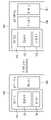
도 1을 참조하면, 프로세서(120) 및 IoT 센서 1(130) 및 배터리 1(140)을 포함하는 IoT 디바이스(100)에 전력 공급을 확장 적용하기 위해, 배터리 2를 추가하고자 하는 요구가 있을 때, 종래의 기술로는, IoT 디바이스(105) 내부에, 배터리 1(140)과 함께 배터리 2(150)를 부가하는 형태로 확장 적용하였다. 이와 같이, 신규하게 배터리 2(150)가 추가된 IoT 디바이스(105)에 대해서는 단순한 부품 추가가 가능한 형태가 아니기 때문에, 디바이스 전체에 대한 구조 변경이 불가피한 불편함이 존재한다. 또한, 기존 IoT 디바이스(100)가 각종 인증 시험을 통과한 상태인 경우, 기존 IoT 디바이스에서 과도한 설계변경이 된 신규 IoT 디바이스(105)는 다시 인증 시험이 필요하게 되는 불편함 또한 존재한다.Referring to FIG. 1 , when there is a request to add a battery 2 in order to extend and apply power supply to the
도 2는 종래 IoT 단말기에 IoT 센서를 확장하는 과정을 설명하기 위한 개념도이다. 도 2의 경우도 역시, 도 1의 경우와 유사하다.2 is a conceptual diagram for explaining a process of extending an IoT sensor to a conventional IoT terminal. The case of FIG. 2 is also similar to the case of FIG. 1 .
도 2를 참조하면, 도 1의 좌측 도면의 IoT 디바이스(100)와 동일한 형태의 IoT 디바이스(100)에 장치 기능 확장을 위해 센서를 추가하고자 하는 요구가 있을 때, 종래의 기술로는, IoT 디바이스(105) 디바이스의 제 1 기판(110) 상에 IoT 센서 2(160)를 부가하는 형태로 확장 적용되었다. 이때, 단순 결합하는 형태로 디바이스가 형성되어 있지 않기 때문에, 제 1 기판(110) 전체를 신규 개발할 필요가 있고, 이에 따라 IoT 디바이스(105) 전체를 신규 개발할 필요가 있었다. 따라서, 전체 구조 변경에 대한 부담이 존재하고, 도 1의 예시에서 설명한 바와 같이, 기존 IoT 디바이스(100)가 각종 인증 시험을 통과한 상태인 경우, 기존 IoT 디바이스에서 과도한 설계변경이 된 신규 IoT 디바이스(105)는 다시 인증 시험이 필요하게 되는 불편함 또한 존재한다.Referring to FIG. 2 , when there is a request to add a sensor to the
상술한 문제점을 해결하기 위한 본 발명의 일 양태에 따른 목적은, IoT 디바이스를 모듈화하여, 사업화 방향에 따라 필요 기능의 모듈을 체결함에 의해 신규 제품을 생성가능한 확장가능한 모듈형 IoT 디바이스를 제공하는 것이다.An object according to an aspect of the present invention for solving the above-described problems is to provide an expandable modular IoT device capable of creating a new product by modularizing the IoT device and connecting the module of the necessary function according to the commercialization direction. .
상기한 목적을 달성하기 위한 본 발명의 일 양태에 따른, 확장가능한 모듈형 IoT 디바이스는, 제 1 기판, 상기 제 1 기판 상의 제 1 프로세서, 상기 제 1 기판 상의 제 1 IoT 센서 및 추가적인 전자 부품과 연결하기 위해 구비되는 커넥터(connector)를 포함할 수 있다.According to an aspect of the present invention for achieving the above object, an expandable modular IoT device includes a first substrate, a first processor on the first substrate, a first IoT sensor on the first substrate, and additional electronic components; It may include a connector (connector) provided for connection.
상기 디바이스는, 상기 IoT 디바이스 내에 배열된 제 1 배터리를 더 포함할 수 있다.The device may further include a first battery arranged in the IoT device.
상기 추가적인 전자 부품은 제 2 배터리를 포함하고, 상기 제 2 배터리로부터의 전력을 제어하는 전력 관리 회로(Power Management Circuit)를 더 포함하되, 상기 전력 관리 회로는, (i) 상기 제 1 배터리만 연결되어 있을 때, 상기 제 1 배터리로부터의 전력을 상기 프로세서로 공급하고, (ii) 상기 IoT 디바이스와 독립하여 배열된 상기 제 2 배터리가 상기 커넥터와 연결되어 있을 때, 상기 제 2 배터리로부터의 전력을 상기 프로세서로 공급할 수 있다.The additional electronic component includes a second battery, and further includes a Power Management Circuit for controlling power from the second battery, wherein the power management circuit comprises: (i) connecting only the first battery supply power from the first battery to the processor, and (ii) supply power from the second battery when the second battery arranged independently of the IoT device is connected to the connector. may be supplied to the processor.
상기 커넥터가 충전용 USB(Universal Serial Bus)와 연결될 때, 상기 전력 관리 회로는, 상기 충전용 USB를 이용하여 제 2 전압으로 상기 프로세서에 전력을 공급하되, 상기 제 2 전압은 상기 제 1 배터리 또는 상기 제 2 배터리의 제 1 전압보다 높을 수 있다.When the connector is connected to a USB (Universal Serial Bus) for charging, the power management circuit supplies power to the processor at a second voltage using the USB for charging, wherein the second voltage is the first battery or It may be higher than the first voltage of the second battery.
상기 커넥터가 상기 충전용 USB와 연결되어 있으면서, 상기 제 1 배터리가 존재함에 대응하여, 상기 전력 관리 회로는, 상기 제 2 전압으로 상기 프로세서에 전력을 공급하면서, 상기 제 1 배터리를 충전하는 모드를 활성화시킬 수 있다.In response to the presence of the first battery while the connector is connected to the USB for charging, the power management circuit performs a mode of charging the first battery while supplying power to the processor with the second voltage. can be activated.
상기 추가적인 전자 부품은 제 2 기판과 상기 제 2 기판 상의 제 2 IoT 센서를 포함하고, 상기 제 2 기판과 상기 제 2 IoT 센서는 상기 IoT 디바이스 내부에 배열될 때, 상기 커넥터는 상기 제 1 기판 상에 배열된 제 1 내부 커넥터이고, 상기 제 2 기판 상에도 제 2 내부 커넥터가 배열되며, 상기 제 1 내부 커넥터와 상기 제 2 내부 커넥터의 연결로 인해 상기 제 1 기판과 상기 제 2 기판이 상기 IoT 디바이스 내에서 모듈화되어 통신할 수 있다.The additional electronic component includes a second board and a second IoT sensor on the second board, and when the second board and the second IoT sensor are arranged inside the IoT device, the connector is disposed on the first board a first internal connector arranged in a , a second internal connector is also arranged on the second board, and the first board and the second board are connected to the IoT due to the connection between the first internal connector and the second internal connector It can be modularized and communicated within the device.
상기 커넥터는 상기 IoT 디바이스와 독립적으로 배열된 제 2 IoT 디바이스와 연결을 위한 제 1 외부 커넥터이며, 상기 제 2 IoT 디바이스도 제 2 프로세서와 제 2 IoT 센서 및 제 2 외부 커넥터를 포함하며, 상기 제 1 외부 커넥터는 상기 제 2 외부 커넥터와 연결되어 상기 제 1 프로세서와 상기 제 2 프로세서가 통신할 수 있다.The connector is a first external connector for connection with a second IoT device arranged independently of the IoT device, and the second IoT device also includes a second processor, a second IoT sensor, and a second external connector, The first external connector is connected to the second external connector so that the first processor and the second processor can communicate.
상기 커넥터를 통한 통신 방식은 UART(Universal Asynchronous Receive/Transmit), I2C(Inter Intergrated Circuit) 및 SPI(Serial Peripheral Interface) 중 적어도 하나를 포함할 수 있다.The communication method through the connector may include at least one of Universal Asynchronous Receive/Transmit (UART), Integrated Circuit (I2C), and Serial Peripheral Interface (SPI).
상기 제 1 프로세서와 상기 제 1 IoT 센서 간의 통신 방식은 제 1 통신 방식을 사용하고, 상기 제 1 기판과 상기 IoT 디바이스 내의 제 2 기판과의 내부 커넥터를 통한 통신 방식은 제 2 통신 방식을 사용하며, 그리고 제 2 IoT 디바이스와의 외부 커넥터를 통한 통신 방식은 제 3 통신 방식을 사용하여 데이터를 송수신할 수 있다.A communication method between the first processor and the first IoT sensor uses a first communication method, and a communication method between the first board and the second board in the IoT device through an internal connector uses a second communication method, , and a communication method through an external connector with the second IoT device may transmit/receive data using a third communication method.
상기한 목적을 달성하기 위한 본 발명의 다른 양태에 따른, 확장가능한 모듈형 IoT 디바이스는, 제 1 기판, 제 1 기판 상의 프로세서, 상기 제 1 기판 상의 제 1 IoT 센서 및 상기 프로세서와 연동하는 안테나를 포함하되, 상기 IoT 디바이스의 내부에 상기 제 1 기판, 상기 프로세서 및 상기 제 1 IoT 센서 이외의 파생 전자 부품을 실장가능하게 구성될 수 있다.According to another aspect of the present invention for achieving the above object, an expandable modular IoT device includes a first substrate, a processor on the first substrate, a first IoT sensor on the first substrate, and an antenna interworking with the processor. Including, but may be configured to be capable of mounting derivative electronic components other than the first substrate, the processor, and the first IoT sensor inside the IoT device.
상기 IoT 디바이스의 바닥(bottom) 면으로부터 수평 방향에 대해 상기 안테나의 측면의 일정 영역에, 기준값 이상의 넓이를 갖는 부품 배열 금지 영역을 설정하여, 상기 파생 전자 부품을 확장하여 연동시킬 때, 상기 부품 배열 금지 영역에는 임의의 부품이 배열되지 않도록 함에 따라 상기 프로세서 및 상기 안테나의 RF(Radio Frequency) 성능이 영향을 받지 않도록 구성될 수 있다.When a component arrangement prohibition area having an area greater than or equal to a reference value is set in a certain area of the side of the antenna in a horizontal direction from the bottom surface of the IoT device, and the derived electronic component is extended and interlocked, the component arrangement It may be configured so that radio frequency (RF) performance of the processor and the antenna is not affected as any components are not arranged in the forbidden area.
상기 바닥 면으로부터 수직 방향에 대해, 상기 프로세서의 상부에 상기 안테나가 배열되고, 상기 수평 방향에 대해, 상기 안테나는 상기 제 1 기판의 주변에 배열되며, 상기 안테나의 길이는 상기 제 1 기판의 길이보다 기준 길이 이상 짧게 형성되어 상기 부품 배열 금지 영역이 상기 제 1 기판의 길이와 상기 안테나의 길이의 마진(margin) 부분에 상기 일정 영역을 확보하도록 형성될 수 있다.In a vertical direction from the bottom surface, the antenna is arranged on the top of the processor, and in the horizontal direction, the antenna is arranged at the periphery of the first substrate, and the length of the antenna is the length of the first substrate The component arrangement prohibition region may be formed to be shorter than the reference length to secure the predetermined region at a margin between the length of the first substrate and the length of the antenna.
상기 안테나, 상기 프로세서, 상기 제 1 IoT 센서 및 상기 제 1 기판을 포함하여 고정영역을 형성하고, 상기 파생 부품은 확장영역에 형성되어 단일 IoT 디바이스로 연동하되, 상기 확장영역은 상기 수평 방향으로, 상기 고정영역의 측면에 형성될 수 있다.A fixed area is formed including the antenna, the processor, the first IoT sensor, and the first substrate, and the derivative part is formed in the extended area and interlocked with a single IoT device, wherein the extended area is in the horizontal direction, It may be formed on a side surface of the fixed region.
상기 확장영역은 높이 측면에서 기준 값 이상 확장되지 못하도록 제한된 공간을 가질 수 있다.The extension area may have a limited space so as not to extend beyond a reference value in terms of height.
상기 파생 부품은 제 2 기판, 제 2 IoT 센서, 배터리 중 적어도 하나를 포함할 수 있다.The derivative component may include at least one of a second substrate, a second IoT sensor, and a battery.
본 발명의 확장가능한 모듈형 IoT 디바이스에 따르면, 모듈화를 통해 신규 제품 개발 필요성 및 인증 절차를 최소화하는 효과가 있다.According to the expandable modular IoT device of the present invention, there is an effect of minimizing the need for new product development and authentication procedures through modularization.
또한, 다양한 IoT 시장의 니즈(needs)에 빠르게 대응할 수 있다.In addition, it can quickly respond to the needs of various IoT markets.
추가적으로, 이미 개발된 제 3 자(3rd party) 센서 단말/보드와 연결하여 사용이 가능하기에 효율적인 제품 확장성을 제공하는 효과가 있다. 즉, 제 3 자 센서 단말에 통신 모듈을 연결하여 통신모듈/안테나/서버/웹/앱의 신규 개발 없이 IoT 통합 솔루션을 손쉽게 구축할 수 있다.In addition, it has the effect of providing efficient product scalability because it can be used in connection with a previously developed3rd party sensor terminal/board. That is, by connecting the communication module to a third-party sensor terminal, it is possible to easily build an IoT integrated solution without new development of communication module/antenna/server/web/app.
도 1은 종래 IoT 단말기에 배터리(battery)를 확장하는 과정을 설명하기 위한 개념도,1 is a conceptual diagram for explaining a process of extending a battery (battery) in a conventional IoT terminal;
도 2는 종래 IoT 단말기에 IoT 센서를 확장하는 과정을 설명하기 위한 개념도,2 is a conceptual diagram for explaining a process of extending an IoT sensor to a conventional IoT terminal;
도 3은 본 발명의 일 실시예에 따른, 확장가능한 모듈형 IoT 디바이스를 나타낸 블록도,3 is a block diagram illustrating an expandable modular IoT device according to an embodiment of the present invention;
도 4은 도 3의 확장가능한 모듈형 IoT 디바이스에 배터리를 확장하는 구조를 설명하기 위한 블록도,4 is a block diagram for explaining a structure for extending a battery in the expandable modular IoT device of FIG. 3;
도 5는 도 4의 배터리 확장 구조시 전원에 따라 전력 경로를 제어하는 방법을 설명하기 위한 개념도,5 is a conceptual diagram for explaining a method of controlling a power path according to a power source in the battery expansion structure of FIG. 4;
도 6은 도 3의 확장가능한 모듈형 IoT 디바이스에 IoT 센서를 확장하는 구조를 설명하기 위한 블록도,6 is a block diagram illustrating a structure for extending an IoT sensor to the expandable modular IoT device of FIG. 3;
도 7은 도 6의 IoT 센서를 디바이스 내부에서 확장한 구조를 나타낸 블록도,7 is a block diagram showing a structure in which the IoT sensor of FIG. 6 is expanded inside the device;
도 8은 도 7의 IoT 디바이스에 외부 IoT 디바이스를 결합하는 구조를 나타낸 블록도,8 is a block diagram showing a structure for coupling an external IoT device to the IoT device of FIG. 7;
도 9는 외부 커넥터 구조 기반의 모듈화된 IoT 디바이스의 추가 개발 필요성을 설명하기 위한 블록도,9 is a block diagram illustrating the need for further development of a modular IoT device based on an external connector structure;
도 10 및 도 11은 본 발명의 다른 실시예에 따른 확장가능한 모듈형 IoT 디바이스의 단면도 및 평면도,10 and 11 are cross-sectional and plan views of an expandable modular IoT device according to another embodiment of the present invention;
도 12 내지 도 14는 도 10 및 도 11의 IoT 디바이스에 추가 IoT 관련 부품을 확장 연계시킨 구조를 예시적으로 나타낸 예시도이다.12 to 14 are exemplary views exemplarily illustrating a structure in which additional IoT-related parts are extended and linked to the IoT device of FIGS. 10 and 11 .
본 발명은 다양한 변경을 가할 수 있고 여러 가지 실시예를 가질 수 있는 바, 특정 실시예들을 도면에 예시하고 상세하게 설명하고자 한다.Since the present invention can have various changes and can have various embodiments, specific embodiments are illustrated in the drawings and described in detail.
그러나, 이는 본 발명을 특정한 실시 형태에 대해 한정하려는 것이 아니며, 본 발명의 사상 및 기술 범위에 포함되는 모든 변경, 균등물 내지 대체물을 포함하는 것으로 이해되어야 한다.However, this is not intended to limit the present invention to specific embodiments, and should be understood to include all modifications, equivalents and substitutes included in the spirit and scope of the present invention.
제 1, 제 2 등의 용어는 다양한 구성요소들을 설명하는데 사용될 수 있지만, 상기 구성요소들은 상기 용어들에 의해 한정되어서는 안 된다. 상기 용어들은 하나의 구성요소를 다른 구성요소로부터 구별하는 목적으로만 사용된다. 예를 들어, 본 발명의 권리 범위를 벗어나지 않으면서 제 1 구성요소는 제 2 구성요소로 명명될 수 있고, 유사하게 제 2 구성요소도 제 1 구성요소로 명명될 수 있다. 및/또는 이라는 용어는 복수의 관련된 기재된 항목들의 조합 또는 복수의 관련된 기재된 항목들 중의 어느 항목을 포함한다.Terms such as first, second, etc. may be used to describe various elements, but the elements should not be limited by the terms. The above terms are used only for the purpose of distinguishing one component from another. For example, without departing from the scope of the present invention, a first component may be referred to as a second component, and similarly, a second component may also be referred to as a first component. and/or includes a combination of a plurality of related listed items or any of a plurality of related listed items.
어떤 구성요소가 다른 구성요소에 "연결되어" 있다거나 "접속되어" 있다고 언급된 때에는, 그 다른 구성요소에 직접적으로 연결되어 있거나 또는 접속되어 있을 수도 있지만, 중간에 다른 구성요소가 존재할 수도 있다고 이해되어야 할 것이다. 반면에, 어떤 구성요소가 다른 구성요소에 "직접 연결되어" 있다거나 "직접 접속되어" 있다고 언급된 때에는, 중간에 다른 구성요소가 존재하지 않는 것으로 이해되어야 할 것이다.When a component is referred to as being “connected” or “connected” to another component, it may be directly connected or connected to the other component, but it is understood that other components may exist in between. it should be On the other hand, when it is said that a certain element is "directly connected" or "directly connected" to another element, it should be understood that the other element does not exist in the middle.
본 출원에서 사용한 용어는 단지 특정한 실시예를 설명하기 위해 사용된 것으로, 본 발명을 한정하려는 의도가 아니다. 단수의 표현은 문맥상 명백하게 다르게 뜻하지 않는 한, 복수의 표현을 포함한다. 본 출원에서, "포함하다" 또는 "가지다" 등의 용어는 명세서상에 기재된 특징, 숫자, 단계, 동작, 구성요소, 부품 또는 이들을 조합한 것이 존재함을 지정하려는 것이지, 하나 또는 그 이상의 다른 특징들이나 숫자, 단계, 동작, 구성요소, 부품 또는 이들을 조합한 것들의 존재 또는 부가 가능성을 미리 배제하지 않는 것으로 이해되어야 한다.The terms used in the present application are only used to describe specific embodiments, and are not intended to limit the present invention. The singular expression includes the plural expression unless the context clearly dictates otherwise. In the present application, terms such as “comprise” or “have” are intended to designate that a feature, number, step, operation, component, part, or combination thereof described in the specification exists, but one or more other features It is to be understood that this does not preclude the possibility of the presence or addition of numbers, steps, operations, components, parts, or combinations thereof.
다르게 정의되지 않는 한, 기술적이거나 과학적인 용어를 포함해서 여기서 사용되는 모든 용어들은 본 발명이 속하는 기술 분야에서 통상의 지식을 가진 자에 의해 일반적으로 이해되는 것과 동일한 의미를 가지고 있다. 일반적으로 사용되는 사전에 정의되어 있는 것과 같은 용어들은 관련 기술의 문맥상 가지는 의미와 일치하는 의미를 가진 것으로 해석되어야 하며, 본 출원에서 명백하게 정의하지 않는 한, 이상적이거나 과도하게 형식적인 의미로 해석되지 않는다.Unless defined otherwise, all terms used herein, including technical or scientific terms, have the same meaning as commonly understood by one of ordinary skill in the art to which this invention belongs. Terms such as those defined in commonly used dictionaries should be interpreted as having a meaning consistent with the meaning in the context of the related art, and should not be interpreted in an ideal or excessively formal meaning unless explicitly defined in the present application. does not
이하, 첨부한 도면들을 참조하여, 본 발명의 바람직한 실시예를 보다 상세하게 설명하고자 한다. 본 발명을 설명함에 있어 전체적인 이해를 용이하게 하기 위하여 도면상의 동일한 구성요소에 대해서는 동일한 참조부호를 사용하고 동일한 구성요소에 대해서 중복된 설명은 생략한다.Hereinafter, preferred embodiments of the present invention will be described in more detail with reference to the accompanying drawings. In describing the present invention, in order to facilitate the overall understanding, the same reference numerals are used for the same components in the drawings, and duplicate descriptions of the same components are omitted.
도 3은 본 발명의 일 실시예에 따른, 확장가능한 모듈형 IoT 디바이스를 나타낸 블록도이다. 도 3에 도시된 바와 같이, 본 발명의 일 실시예에 따른 확장가능한 모듈형 IoT 디바이스(200)는 기판(210), 프로세서(220), IoT 센서(230) 및 배터리(240)를 포함할 수 있다.3 is a block diagram illustrating an expandable modular IoT device according to an embodiment of the present invention. As shown in FIG. 3 , the expandable modular
도 3의 촤측 도면을 참조하면, IoT 디바이스(200)는 기판(210) 상에 프로세서(220) 및 IoT 센서(230)가 전기적으로 연결되어 배열되고, 배터리(240)가 기판(210)에 전기적으로 연결되어, 전력을 공급하는 구조를 갖는다.Referring to the drawing on the side of FIG. 3 , in the
여기서, 기판(210)는 브래드보드(bread board), 아두이노(Arduino) 기판, PCB 기판 등으로 구현될 수 있다.Here, the
프로세서(220)는 마이크로 프로세서(Microprocessor) 및/또는 MCU(Micro Controller Unit)로 구현될 수 있다. 프로세서(220)는 통신 모듈을 포함할 수 있다. MCU와 통신 모듈은 하나의 프로세서로 구현될 수 있고, 독립된 프로세서들로 구현될 수 있다. 이때, 통신 모듈은 다양한 기법의 RF(Radio Frequency) 방식을 지원한다. 예를 들어, 블루투스, 지그비, 와이파이와 같은 근거리 통신뿐만 아니라 LTE, 5G와 같은 광대역 통신을 지원할 수 있다. 보다 바람직하게는, IoT용 통신 방식인 LoRa 및 NB-IoT 등의 통신방식을 지원할 수 있다. 프로세서(220)는 IoT 동작 정보를 포함하는 소스코드에 의해 동작할 수 있다. 프로세서(220)는 다른 컴퓨팅 장치와 연결되어, 키보드 및 마우스와 같은 입력 장치를 통해 IoT 동작 정보와 관련된 소스코드를 사용자가 입력함에 의해 다양한 제어 기능을 수행할 수 있다.The
IoT 센서(230)는 온도, 압력, 광, 소리와 같은 물리적인 양이나 그 변화를 감지하거나 계측하여 전기적 신호로 변환하는 감지 장치를 나타낸다. 여기에는, 광 센서, 근접 센서, 수분 센서, 초음파 센서, 수질 센서, 수위 센서, 모션 센서, 자이로스코프 센서, 이미지 센서, 열/연기 센서, 적외선 센서, 화학 센서, 진동 센서, 온도 센서, 압력 센서, 가스 센서, 음향 센서, 수정 진동자 저울(quartz crystal microbalance, QCM), 정전 프로브 (Langmuir probe), 자기 센서(magnetic probe), 분광 분석기(spectroscopy) 또는 이온종 질량 분석기(mass spectrometer) 등이 포함될 수 있지만 반드시 이에 한정되는 것은 아니다. 경우에 따라서는, LED, 스위치와 같은 디지털 입출력 주변기기 및/또는 DC 모터, 서보모터와 같은 PWM(Pulse Width Modulation) 입출력 주변기기 등도 포함될 수 있다.The
도 3의 우측 도면을 참조하면, IoT 디바이스(200)에, 하드웨어 스팩(Hardware Specification) 변경을 위해, 배터리 및/또는 IoT 센서와 같은 부품을 추가할 수 있다. 이때, 추가되는 전기적 부품은 배터리, IoT센서 뿐만 아니라, 다양한 전자부품들(메모리 등)을 포함할 수 있다.Referring to the right drawing of FIG. 3 , components such as a battery and/or an IoT sensor may be added to the
먼저, 전력 기능 확장을 위해, 배터리(250)가 포함된 디바이스 2(202)를 연결시킬 수 있다. 이때, 커넥터(connector)를 이용하여 IoT 디바이스(200)에 과도한 설계 변경 없이, 전력을 VBAT 전압으로 공급할 수 있다. 이를 위해, IoT 디바이스(200)(디바이스 1)도 커넥터(미도시)를 포함하여 모듈화된 형태로 형성되어 다른 전력을 입력받거나 전력을 출력할 수 있도록 구현된다. 또한, 디바이스 2(202)도 커넥터를 포함하여 모듈화되는 것이 바람직하다. 이에 따라, IoT 디바이스(200)의 커넥터와 디바이스 2(202)의 커넥터가 서로 결합하여 VBAT로 전력을 송수신할 수 있다.First, in order to expand the power function, the device 2 202 including the
다른 예에서, IoT 디바이스(200)는 센싱 기능 확장을 위해, IoT 센서 2(265)가 포함된 디바이스 3(204)과 연결될 수 있다. 이를 위해, 전력을 위한 커넥터와 다른 형태 또는 다른 통신 방식의 별도의 커넥터가 배열될 수 있다. 디바이스 3(204)은 제 2 기판(260) 상에 IoT 센서 2(265)가 전기적으로 연결된 형태로 형성되되, 외부 커넥터를 포함하여 모듈화된 형태를 가질 수 있다. 이를 통해, 디바이스 1(200)의 상기 별도의 커넥터와 디바이스 3(204)의 커넥터를 통해 IoT 센서(265)가 결합될 수 있다. 상기 커넥터들 간의 연결은 UART(Universal Asynchronous Receive/Transmit), I2C(Inter Intergrated Circuit) 및 SPI(Serial Peripheral Interface) 중 적어도 하나의 방식으로 연결될 수 있다. UART는 비동기 통신으로, 데이터를 원활하게 송수신하기 위해 동기 신호(Clock)을 대체하는 방법을 사용하는 통신 방식이다. UART에는 공유 클럭이 없으므로 데이터를 올바르게 디코딩하기 위해 동일한 타이밍(Baud Rate)를 구성하고 일치시키는 것이 바람직하다. I2C 통신은 데이터를 주고 받기 위한 선(SDA) 하나와 송수신 타이밍 동기화를 위한 클럭 선(SCL) 하나를 통해 데이터를 송수신하는 방식이다. 하나의 마스터(Master)와 하나 이상의 슬레이브(Slave)로 이루어지며, 슬레이브는 최대 127개까지 연결할 수 있다. SPI 방식은 1:N 통신을 지원하는 동기식 통신 방식이다. 반드시 하나의 마스터와 하나 이상의 슬레이브 기기가 존재해야 한다. 데이터를 전송하고 수신하는 선이 따로 있기 때문에 전송과 수신이 동시에 이루어질 수 있어서 송수신 하나의 선으로 이루어지는 I2C 통신에 비해 속도가 빠르다. 따라서, 이더넷 통신 같은 속도가 중요한 곳에 사용되는 것이 바람직하다.In another example, the
본 발명의 또 다른 실시예에 따르면, 배터리와 IoT 센서 이외에, 다른 IoT 관련 부품이 커넥터를 통해 결합될 수 있는 형태로 모듈화되어 형성될 수 있다. 예를 들어, 메모리(memory), 다른 프로세서, 인코더/디코더, 컨버터/인버터 등의 전자부품 등도 모듈화되어 커넥터를 통해 결합될 수 있다. 이때, 디바이스 1이 암형(female) 커넥터를 가지고 있으면, 디바이스 2는 대응하는 수형(male) 커넥터를 갖는 것이 바람직하다. 예를 들어, 하나의 디바이스가 돌출된 핀(pin)을 가지고 있으면, 다른 디바이스는 돌출된 핀을 수용하는 형상의 커넥터를 가지는 것이 바람직하다. 모듈화는 내부 또는 외부 커넥터를 포함하여 특별한 처리 없이 타 디바이스 또는 다른 부품에 결합 가능한 형태로 하나의 부품 뿐만 아니라 복수 개의 부품을 구성하는 것을 의미한다.According to another embodiment of the present invention, in addition to the battery and the IoT sensor, other IoT-related parts may be modularized and formed in a form that can be coupled through a connector. For example, electronic components such as a memory, another processor, an encoder/decoder, and a converter/inverter may also be modularized and coupled through a connector. At this time, if device 1 has a female connector, device 2 preferably has a corresponding male connector. For example, if one device has a protruding pin, the other device preferably has a connector shaped to receive the protruding pin. Modularization means configuring not only one part but also a plurality of parts in a form that can be combined with other devices or other parts without special processing including internal or external connectors.
본 발명의 추가적인 실시예에 따르면, 지면에서 수직한 방향에서 IoT 디바이스(200)를 바라봤을 때, 좌측과 우측, 양 측면 방향으로, 전력 관련 커넥터를 배열하여 배터리와 같은 전력 관련 모듈화된 디바이스를 연결가능하게 하고, 상측과 하측, 두 방향으로, 센서를 포함하는 데이터 송수신 기능 커넥터(UART, I2C, SPI 기반 커넥터)를 배열하여 모듈화된 전자 부품을 연결가능하게 구성할 수 있다. 반대가 되도 무방하다. 이때, 커넥터들은 하나의 면에 다수 개가 배열될 수 있다. IoT 디바이스(200)에 결합되는 배터리 관련 디바이스들(202) 뿐만 아니라, 전자 부품 관련 디바이스들(204)도 좌우측 및/또는 상하측에 커넥터를 하나 또는 그 이상 배열하여, IoT 디바이스(200)에 결합됨과 동시에 다른 디바이스도 연결가능하도록 구성될 수 있다. 이를 통해, 다양한 IoT 기기가 연계하여 무한히 확장가능하게 모듈화된 형태로 구현될 수 있다. 이에 따라 하나의 면에, 다수 개의 배터리 모듈 및/또는 다수 개의 IoT 센서 모듈이 결합될 수 있다.According to an additional embodiment of the present invention, when the
추가적으로, 커넥터는 지면에 수직한 방향으로 상측뿐만 아니라 하측에도 배열될 수 있다. 이에 따라 양면에 커넥터가 배열되어, 보다 자유로운 연결이 가능하도록 구성될 수 있다.Additionally, the connector may be arranged not only on the upper side but also on the lower side in a direction perpendicular to the ground. Accordingly, connectors are arranged on both sides, so that a more free connection may be possible.
도 4는 도 3의 확장가능한 모듈형 IoT 디바이스에 배터리를 확장하는 구조를 설명하기 위한 블록도이다.FIG. 4 is a block diagram illustrating a structure for extending a battery in the expandable modular IoT device of FIG. 3 .
도 4를 참조하면, 제 1 기판(310) 상에 프로세서(320)(MCU와 통신모듈을 포함함)에, IoT 센서(330)가 배열되며, 추가적으로 배터리 1(340)를 포함하는 IoT 디바이스(300)에, 배터리 기능 확장에 따른 신규 제품 개발이 필요할 때, 디바이스 전체 구조를 변경하지 않고, 간단하게, 배터리(350)가 포함된 모듈화된 디바이스 2(302)를 연결시킬 수 있다. 이때, 전력 커넥터(connector)를 이용하여 IoT 디바이스(300)에 과도한 설계 변경 없이, 전력을 VBAT 전압으로 공급할 수 있다. 이때, 두 디바이스(300, 302)의 전력 커넥터들 중 하나는 돌출된 다수의 핀으로 형성될 수 있고, 다른 하나는 상기 돌출된 핀을 수용하는 형태로 형성될 수 있다. 더욱이, 이러한 하드웨어의 조립 및 연결의 자유도를 향상시키기 위해, 서로 다른 면에 커넥터가 구비될 수 있다. 예를 들어, 디바이스 1(300)의 상면에 커넥터가 구비되면, 디바이스 2(302)의 하면에 커넥터가 구비되어 서로 용이하게 착탈될 수 있도록 할 수 있다. 위와 같이 양 디바이스(300, 302)가 모듈형으로 서로 용이하게 확장가능하게 구성됨에 따라, 배터리 확장에 의한 하드웨어 스펙 변경에도 불구하고, 추가적인 통신모듈을 개발하지 않아도 되고, 각종 인증을 생략할 수 있다. 즉, 디바이스 2(302)를 통해 변경되는 부분만 추가 개발하여 모듈화한 후 장착하면 되는 것이다.Referring to FIG. 4 , an
도 5는 도 4의 배터리 확장 구조시 전원에 따라 전력 경로를 제어하는 방법을 설명하기 위한 개념도이다.FIG. 5 is a conceptual diagram for explaining a method of controlling a power path according to a power source in the battery expansion structure of FIG. 4 .
도 5를 참조하면, 다양한 전원(power source)이 IoT 디바이스(400)에 확장 연결될 때, 적절한 전력 제어가 필요할 수 있다. 먼저, IoT 디바이스(400)가, 전술한 바와 같이, 기판 상에 프로세서(420)가 구비되어 있으며, 여기에, VSYS 전압이 프로세서(420)로 흘러들어가게 전력 관리 회로(422)가 전력 경로를 제어한다. 전압 관리 회로(422)는 내부 배터리(440) 및/또는 커넥터(424)와 연결되어 외부로부터의 전력을 수신할 수 있도록 되어있으며, 연결 관계에 따라 적절한 시나리오에 의해 전력(VSYS)을 프로세서(420)로 공급하는 기능을 수행한다.Referring to FIG. 5 , when various power sources are extended and connected to the
본 발명의 실시예에 따르면, 전력 관리 회로(422)는 연결되는 전원에 따라 전력 경로를 제어하여 하나의 커넥터(424)로 내부 배터리(440)의 충전뿐만 아니라 배티러 확장이 가능한 구조를 형성한다.According to an embodiment of the present invention, the
먼저, 내부 배터리(440)만 연결되어 있는 경우, 프로세서(420)로 공급되는 전력(VSYS)은 내부배터리(440)로부터의 전력이 된다. 이때, 전압(VSYS)은 내장형 소형 배터리의 전압(VBAT)인 3.7V일 수 있다.First, when only the internal battery 440 is connected, the power VSYS supplied to the
다음으로, 커넥터(424)를 통해 외부 배터리(450)만 연결된 경우, 프로세서(420)로 공급되는 전력(VSYS)은 외부배터리(450)로부터의 전력이 된다. 이때, 전압(VSYS)은 외장형 보조 배터리의 전압(VBAT)인 3.7V일 수 있다.Next, when only the external battery 450 is connected through the
또한, 커넥터(424)를 통해 충전용 USB(470)만 연결되어 충전용 USB(470)를 통해 전원을 끌어오는 경우, 프로세서(420)로 공급되는 전력(VSYS)은 충전용 USB를 통한 전력이 된다. 이때, 충전용 USB의 전압이 5.0V임에도 불구하고, 전력 관리 회로(422)는 안정적인 전력 공급을 위해, 상기 전압(VSYS)을 4.2V로 하여, 프로세서(420)에 공급할 수 있다.In addition, when only the
추가적으로, 내부 배터리(440)와 커넥터(424)를 통해 외부 배터리(450)가 함께 연결되어 있은 경우, 프로세서(420)로 공급되는 전력(VSYS)은 외부배터리(450)로부터의 전력이 되도록 한다. 이때, 내부 배터리(440)까지 충전이 되도록 하면, 외부 보조 배터리(450)에 부하가 많이 걸리기에, 충전 모드는 비활성화 상태를 유지하도록 제어한다.Additionally, when the internal battery 440 and the external battery 450 are connected together through the
다른 예에서, 내부 배터리(440)와 커넥터(424)를 통해 충전용 USB(470)가 함께 연결되어 있은 경우, 프로세서(420)로 공급되는 전력(VSYS)은 충전용 USB(470)로부터의 전력이 되도록 한다. 따라서, 전압(VSYS)을 4.2V로 하여, 프로세서(420)에 공급할 수 있다. 이때, 충전용 USB(470)은 안정적으로 전력을 공급받을 수 있기 때문에, 내부 배터리(440)까지 충전이 되도록 하는 것이 바람직하다. 따라서, 전압(VSYS)을 4.2V로 하여 안정적으로 공급하면서, 내부 배터리(440)의 충전 모드는 활성화시켜 내부 배터리(440)의 충전도 함께 수행될 수 있도록 한다.In another example, when the internal battery 440 and the
도 6은 도 3의 확장가능한 모듈형 IoT 디바이스에 IoT 센서를 확장하는 구조를 설명하기 위한 블록도이다.6 is a block diagram illustrating a structure of extending an IoT sensor to the expandable modular IoT device of FIG. 3 .
도 6을 참조하면, 도 3의 IoT 디바이스와 동일한 구성의 모듈화된 IoT 디바이스(500)는 디바이스(504)를 결합되어 기능이 확장되어 사용될 수 있다. 이때, IoT 디바이스(500)는 커넥터(미도시)를 통해 연결될 수 있다. 디바이스(504)는 IoT 디바이스(500)의 커넥터에 대응하는 형상의 커넥터(미도시)를 기반으로 모듈화되어 IoT 디바이스(500)에 연결된다. 디바이스(504)는 제 2 기판(560) 상에 IoT 센서 2(565)를 포함하고 있다. 그리고, 두 커넥터 간의 연결은 UART, I2C 및 SPI 중 적어도 하나의 방식일 수 있다.Referring to FIG. 6 , the
위와 같은 모듈형의 두 디바이스(500, 504)의 형태에 따라, 신규한 기능을 위해 제품 개발이 필요할 때에도, 과도한 설계 변경 없이 변경되는 부분만 개발하여 모듈로 연결만 하면 되기에, 제품 개발의 효율이 높아지고, 개발비용 부분에서도 이득을 볼 수 있다.According to the form of the two
도 7은 도 6의 IoT 센서를 디바이스 내부에서 확장한 구조를 나타낸 블록도이다.7 is a block diagram illustrating a structure in which the IoT sensor of FIG. 6 is expanded inside a device.
도 7을 참조하면, 디바이스의 확장은 디바이스 외부에 전자 부품을 연결하는 것만을 의미하는 것은 아니다. 내부 연결도 가능하다. 즉, 센서 내장형으로 모듈형 IoT 디바이스(600)가 설계될 수 있다.Referring to FIG. 7 , the expansion of a device does not mean only connecting an electronic component to the outside of the device. Internal connections are also possible. That is, the
보다 구체적으로, IoT 디바이스(600)는 제 1 기판(610) 상에 프로세서(620)(MCU와 통신모듈을 포함할 수 있음) 및 IoT 센서(630)을 배열하고, 제 1 기판(610)은 내부 커넥터(626)를 포함한다. 이때, IoT 센서 디바이스(700) 내의 프로세서(720)과 IoT 센서(630)은 UART, I2C 및 SPI 중 적어도 하나의 방식으로 서로 연결되어, 데이터를 주고 받을 수 있다.More specifically, the
또한, IoT 디바이스(600)는 제 2 기판(660) 상에 IoT 센서(665)와 내부 커넥터(628)를 포함한다. 두 개의 기판(610, 660)은 UART, I2C 및 SPI 중 적어도 하나의 방식으로 서로 연결되어, 데이터를 주고 받을 수 있다. 통신 방식은 IoT 센서(665)의 통신 방식 지원 여부를 기반으로 프로세서(620)에서 선택할 수 있다. 내부 커넥터(626, 628)는 데이터를 송수신을 위한 커넥터로 서로 대응되는 형태를 가질 수 있다.In addition, the
도 8은 도 7의 IoT 디바이스에 외부 IoT 디바이스를 결합하는 구조를 나타낸 블록도이다.8 is a block diagram illustrating a structure of coupling an external IoT device to the IoT device of FIG. 7 .
도 8을 참조하면, 도 8 좌측의 IoT 디바이스(700)는 도 7의 IoT 내부 확장형 IoT 디바이스(600)와 동일한 구성을 갖는다. 여기에, 이미 개발된 제 3 자 IoT 센서 디바이스(702)를 연결할 수 있다. 상기 IoT 센서 디바이스(702)는 제 3 기판(770) 상에 프로세서(772)와 IoT 센서 3(774)을 포함한다. 상기 IoT 센서 디바이스(702) 내의 프로세서(772)와 IoT 센서 3(774)도 UART, I2C 및 SPI 중 적어도 하나의 방식으로 서로 연결되어, 데이터를 주고 받을 수 있다.Referring to FIG. 8 , the
한편, 두 디바이스(700, 702) 간의 연결은 외부 커넥터(724, 722)를 통해 이루어질 수 있다. IoT 디바이스(702)는 외부 커넥터(724)를 통해 디바이스과 연결됨에 의해, 별도의 통신모듈, 안테나, 서버, 웹 및 앱(application)의 개발 없이, IoT 디바이스(700)과 연결하여 IoT 통합 솔루션을 구축할 수 있다. 이때, 내부 커넥터(726, 728)과 외부 커넥터(724, 722)는 서로 다른 형태 또는 다른 통신 방식의 커넥터일 수 있다. 통신 방식은 IoT 디바이스(702)의 프로세서(772)의 MCU의 지원 여부에 따라 IoT 디바이스(700)에서 UART, I2C 및 SPI 중 적어도 하나의 방식을 선택 가능하다.Meanwhile, a connection between the two
도 9는 외부 커넥터 구조 기반의 모듈화된 IoT 디바이스의 추가 개발 필요성을 설명하기 위한 블록도이다.9 is a block diagram illustrating the need for further development of a modular IoT device based on an external connector structure.
도 9를 참조하면, 본 발명의 일 실시예에 따라, 복수 개의 외부커넥터(824, 826)를 가진 IoT 디바이스(800)는 하드웨어 스펙 변경에 따라 신규 제품 개발 필요성에 의해, IoT 디바이스(802) 및 IoT 디바이스(804)와 외부커넥터(822) 및 외부커넥터(828)을 이용하여 연결될 수 있다.Referring to FIG. 9 , according to an embodiment of the present invention, the
특히, 도 9의 우측 도면을 참조하면, 외부커넥터 연결 구조로 된 모듈화된 IoT 디바이스는 IoT 디바이스(800)와 대응하는 형식으로 디바이스들(802, 804)를 제작하게 되는데, 이때, IoT 디바이스(802)의 케이스, 제 2 기판(860), 배터리(865), IoT 디바이스(804)의 케이스, 제 3 기판(870), IoT 센서 2(875)를 모두 개발해야 하는 부담이 존재한다.In particular, referring to the right drawing of FIG. 9 , a modular IoT device having an external connector connection structure produces
특히, IoT 디바이스(800)과 IoT 디바이스(802)의 접합부위 1과 IoT 디바이스(800)과 IoT 디바이스(804)의 접합부위 2에서 방수, 방진, 내구성 등의 신뢰성 문제가 생길 수 있다. 또한, 접합부위를 보강함에 따른 제품 사이즈 증가도 불가피하다. 추가적으로, 안테나의 성능은 내부 부품 및 기구 형태에 따라 방사패턴이 달라져서 성능 차이를 유발할 수 있는데, IoT 디바이스(800)의 안테나 성능이 IoT 디바이스(802)의 신규 기구 추가에 따라 영향을 받게 되는 문제점이 있다.In particular, reliability problems such as waterproofing, dustproofing, and durability may occur in the junction part 1 of the
결과적으로, 외부 커넥터 실장 타입은 제품 소형화 측면 및 안테나 방사 효율 측면에서 효과적이지 못하다. 보다 상세하게는, IoT 디바이스 설계시 매우 중요한 고려사항은 소형화, 방수 및 방진, 그리고 RF 성능이다. 따라서, 제품 파생시 위와 같은 고려사항에 대한 개발 및 검토를 최소한으로 하여 개발비용 및 시간을 최소화하는 것이 바람직하다. 외부 커넥터를 적용하면 소형 제품 사이즈의 20~30% 이상의 공간이 낭비되기 때문에, 일체형 기구 적용이 적절할 수 있다. 즉, 기구 내부에서 모듈화를 수행하는 것이 바람직할 수 있다.As a result, the external connector mounting type is not effective in terms of product miniaturization and antenna radiation efficiency. More specifically, very important considerations when designing IoT devices are miniaturization, water and dust resistance, and RF performance. Therefore, it is desirable to minimize development cost and time by minimizing development and review of the above considerations when derivation of a product. If an external connector is applied, space of 20 to 30% or more of the size of a small product is wasted, so the application of an integrated mechanism may be appropriate. That is, it may be desirable to perform modularization within the instrument.
도 10 및 도 11은 본 발명의 다른 실시예에 따른 확장가능한 모듈형 IoT 디바이스의 단면도 및 평면도이다.10 and 11 are cross-sectional and plan views of an expandable modular IoT device according to another embodiment of the present invention.
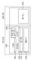
도 10을 참조하면, 단면도로 바라봤을 때, IoT 디바이스(900)는 배터리(940), 제 1 기판(910), 프로세서(920), IoT 센서(930) 및 안테나(905)를 포함한다. 이때, 배터리(940)가 가장 하단에 배열되고, 그 위에, 제 1 기판(910)이 배열되며, 제 1 기판(910) 상의 일측면에 프로세서(920)가 배열되고, 다른 측면에 IoT 센서(915)가 전기적으로 연결되어 배열될 수 있다. 프로세서(920)와 IoT 센서(915)는 제 1 기판(910) 상에 나란히 배열될 수 있다. 안테나(905)는 프로세서(920) 상에 간격을 두고 배열될 수 있다. 여기서, 프로세서(920)는 통신 모듈일 수 있고, 안테나(905)와 연계하여 무선 신호를 송수신할 수 있다. 이러한 배열에서, IoT 디바이스(900)에는 안테나(905)의 측면 영역에 부품 배열 금지 영역(915)을 설정하여, 어떠한 전자 부품의 배치가 금지되도록 하는 것이 바람직하다. 즉, 임의의 전자 부품의 배열을 방지함에 따라 프로세서(920) 및 안테나(905)의 RF 성능이 영향을 받지 않도록 구성하는 것이 바람직하다.Referring to FIG. 10 , when viewed in cross-sectional view, the
도 11을 참조하면, 평면도로 바라봤을 때, 제 1 기판(910) 상에 좌측에는 프로세서(920)가 우측에는 IoT 센서(930)가 배열될 수 있다. 그리고, 안테나(905)는 상기 제 1 기판(910)을 둘러싸는 형태로, 그 주변에 배열될 수 있다. 안테나(905)는 제 1 기판(910)의 상부 및 하부에 배열될 수 있으며, 좌측 또는 우측 중 하나의 면에도 배열될 수 있다. 안테나(905)는 프로세서(920)와 연계하여 동작하기 때문에, 프로세서(920)와 대응하는 측면에 배열된다. 따라서, 안테나(905)가 제 1 기판(910)의 좌측에 치우쳐져서 배열될 때, 부품 배열 금지 영역(915)은 안테나(905)의 우측 부분에 위치할 수 있다. 특히, 부품 배열 금지 영역(915)은 제 1 기판(910)의 길이와 안테나(905)의 길이를 비교할 때, 그 마진(margin) 부분에 배열될 수 있다. 이때, 부품 배열 금지 영역(915)의 기준 값 이상의 일정한 넓이를 갖는 것이 바람직하다. 상기 기준 넓이 확보를 위해, 상기 안테나(905)의 길이는 제 1 기판(910)의 길이 보다 기준 길이 이상 짧게 형성되는 것이 바람직하다. 부품 배열 방지 영역(915)은 최소 4cm2 이상의 영역으로 구성되는 것이 바람직하다.Referring to FIG. 11 , when viewed from a plan view, a
도 12 내지 도 14는 도 10 및 도 11의 IoT 디바이스에 추가 IoT 관련 부품을 확장 연계시킨 구조를 예시적으로 나타낸 예시도이다.12 to 14 are exemplary views exemplarily illustrating a structure in which additional IoT-related parts are extended and linked to the IoT device of FIGS. 10 and 11 .
도 12를 참조하면, IoT 디바이스의 고정 영역(도 10 및 도 11의 기본 구성요소를 모듈형으로 갖춘 형태의 IoT 디바이스)에 안테나(1005), 제 1 기판(1010), 프로세서(1020), IoT 센서(1030) 및 배터리 1(1040)를 포함한다. 또한, 부품 배열 금지 영역을 추가로 포함하여, 해당 영역에는 어떠한 부품도 배열되지 않도록 구성된다. 그리고, 고정 영역의 수평 방향에 확장 영역을 구분하여 신규 하드웨어 스펙에 따른 파생 전자 부품은 확장 영역에만 배열될 수 있도록 한다. 즉, 확장 영역 내에서 자유로운 형태로 무제한 디바이스의 파생이 가능하도록 한다. 도 12의 실시예에서는, 제 2 기판(1050) 상의 IoT 센서 2(1052) 및 배터리 2(1054)를 포함하는 IoT 기구가 내부적으로 모듈화되어 외부 커넥터를 적용하지 않고 하나의 디바이스로 확장된다.12, the
또한, 도 13을 참조하면, 고정영역의 배터리 3(1040)이 확장 영역까지 파생되어, 그 폭이 좀 더 긴 형태로 형성되며, 확장 영역에 추가적으로, 제 3 기판(1060) 상에 IoT 센서 3(1062) 및 배터리 4(1066)을 포함하는 IoT 기구가 내부적으로 모듈화되어 확장된 형태로 구성된다.In addition, referring to FIG. 13 , the battery 3 1040 in the fixed area is extended to the extended area and has a longer width, and the IoT sensor 3 is formed on the third substrate 1060 in addition to the extended area. The IoT device including the 1062 and the battery 4 1066 is internally modularized and configured in an expanded form.
추가적으로, 도 14를 참조하면, 확장 영역에 배터리 5(1076)가 내부적으로 모듈화되어 하나의 IoT 디바이스에서 확장된 형태로 구성된다.Additionally, referring to FIG. 14 , the battery 5 ( 1076 ) is internally modularized in the extended area and configured in an expanded form in one IoT device.
이러한 부품 배치 금지 영역 이외의 확장 영역에 파생 부품을 배열함에 따라, 소형화, 방수, 방진과 관련된 이슈를 검토할 필요성이 없어지고, 통신모듈(프로세서) 및 안테나 성능에 대한 이슈를 검토할 필요성도 없어지는 이점이 있다.By arranging derivative parts in the extended area other than the area where parts are prohibited, there is no need to review issues related to miniaturization, waterproofing, and dustproofing, and there is no need to review issues related to communication module (processor) and antenna performance. has an advantage.
특히, 부품 배열 금지 영역에 추가적으로, 확장 영역의 높이를 기준값으로 제한함에 따라, 통신모듈 및 안테나의 RF 성능이 영향을 받지 않도록 하는 것도 바람직하다.In particular, in addition to the component arrangement prohibited area, it is also desirable to limit the height of the extended area to a reference value so that the RF performance of the communication module and the antenna is not affected.
이상 도면 및 실시예를 참조하여 설명하였지만, 본 발명의 보호범위가 상기 도면 또는 실시예에 의해 한정되는 것을 의미하지는 않으며 해당 기술 분야의 숙련된 당업자는 하기의 특허 청구의 범위에 기재된 본 발명의 사상 및 영역으로부터 벗어나지 않는 범위 내에서 본 발명을 다양하게 수정 및 변경시킬 수 있음을 이해할 수 있을 것이다.Although described above with reference to the drawings and embodiments, it does not mean that the scope of protection of the present invention is limited by the drawings or embodiments, and those skilled in the art can appreciate the spirit of the present invention described in the claims below. And it will be understood that various modifications and changes can be made without departing from the scope of the present invention.
Claims (15)
Translated fromKoreanPriority Applications (2)
| Application Number | Priority Date | Filing Date | Title |
|---|---|---|---|
| US17/909,754US20230422420A1 (en) | 2021-02-26 | 2021-11-05 | Scalable modular internet-of-things device |
| CN202180026911.XACN115399079B (en) | 2021-02-26 | 2021-11-05 | Scalable, modular IoT device |
Applications Claiming Priority (4)
| Application Number | Priority Date | Filing Date | Title |
|---|---|---|---|
| KR20210026882 | 2021-02-26 | ||
| KR10-2021-0026882 | 2021-02-26 | ||
| KR10-2021-0143267 | 2021-10-26 | ||
| KR1020210143267AKR20220122921A (en) | 2021-02-26 | 2021-10-26 | OPEN-ENDED MODULAR IoT DEVICE |
Publications (1)
| Publication Number | Publication Date |
|---|---|
| WO2022181928A1true WO2022181928A1 (en) | 2022-09-01 |
Family
ID=83048586
Family Applications (1)
| Application Number | Title | Priority Date | Filing Date |
|---|---|---|---|
| PCT/KR2021/015990CeasedWO2022181928A1 (en) | 2021-02-26 | 2021-11-05 | Scalable modular internet-of-things device |
Country Status (4)
| Country | Link |
|---|---|
| US (1) | US20230422420A1 (en) |
| KR (1) | KR102723495B1 (en) |
| CN (1) | CN115399079B (en) |
| WO (1) | WO2022181928A1 (en) |
Citations (5)
| Publication number | Priority date | Publication date | Assignee | Title |
|---|---|---|---|---|
| KR101516753B1 (en)* | 2013-07-31 | 2015-05-04 | 엠디에스테크놀로지 주식회사 | Scalable 3g gateway m2m device by block |
| KR101632710B1 (en)* | 2015-07-09 | 2016-06-22 | 엠디에스테크놀로지 주식회사 | LTE GATEWAY IoT DEVICE AND METHOD FOR EXPANDING DEVICE USING THE SAME |
| US20160209899A1 (en)* | 2015-01-05 | 2016-07-21 | iDevices, LLC | Iot communications bridging power switch |
| KR20190043774A (en)* | 2017-10-19 | 2019-04-29 | 주식회사 하이엔시스 | IoT apparatus for collecting data from sensor of various types, and method thereof |
| WO2020131121A1 (en)* | 2018-12-21 | 2020-06-25 | Intel Corporation | Modular system for internet of things |
Family Cites Families (24)
| Publication number | Priority date | Publication date | Assignee | Title |
|---|---|---|---|---|
| US20050280550A1 (en)* | 2004-06-16 | 2005-12-22 | Ivan William Partners, Inc. Corporation | Modal light-emitting device for mobile signal output devices methods and systems |
| US8706932B1 (en)* | 2007-08-30 | 2014-04-22 | Virident Systems, Inc. | Replaceable non-volatile memory apparatus with a plurality of pluggable electrical connectors |
| KR20120030337A (en)* | 2009-04-06 | 2012-03-28 | 더 유니버시티 오브 아크론 | Battery pack management unit and how to use it to extend the life of the battery pack |
| US8762605B2 (en)* | 2011-11-30 | 2014-06-24 | Apple Inc. | Adapter for electronic devices |
| US8665599B2 (en)* | 2012-01-06 | 2014-03-04 | Hugee Technology Co., Ltd. | Portable external power-supplying device |
| WO2013130124A1 (en)* | 2012-02-29 | 2013-09-06 | Deka Products Limited Partnership | System and method for powering a device |
| US9153987B2 (en)* | 2012-03-07 | 2015-10-06 | Micrel, Inc. | Battery charger voltage control method for instant boot-up |
| CN202872406U (en)* | 2012-09-19 | 2013-04-10 | 青岛海信移动通信技术股份有限公司 | Interface multiplexing circuit and mobile terminal |
| CN105378603B (en)* | 2013-11-26 | 2019-09-10 | Lg电子株式会社 | Portable keyboard and loudspeaker assembly |
| US9842784B2 (en)* | 2014-06-23 | 2017-12-12 | Zglue, Inc. | System and methods for producing modular stacked integrated circuits |
| CN105335311A (en)* | 2014-07-04 | 2016-02-17 | 纬创资通股份有限公司 | Portable electronic device and power management method |
| CN104967199B (en)* | 2015-08-05 | 2018-07-10 | 青岛海信移动通信技术股份有限公司 | Fast charge method and mobile terminal |
| KR102512986B1 (en)* | 2015-11-17 | 2023-03-22 | 삼성전자주식회사 | Electronic system and electronic device |
| US10715599B2 (en)* | 2015-11-30 | 2020-07-14 | Verizon Patent And Licensing, Inc. | Internet of things (IoT) platform and application framework |
| US9929772B2 (en)* | 2016-02-05 | 2018-03-27 | Apana Inc. | Low power, high resolution automated meter reading and analytics |
| KR101696151B1 (en)* | 2016-06-09 | 2017-01-12 | 신재광 | MODULAR ROBOTICS SYSTEM BASED ON IoT |
| US9839267B1 (en)* | 2016-12-29 | 2017-12-12 | Shadecraft, Inc. | Shading system with artificial intelligence application programming interface |
| US10094138B2 (en)* | 2016-12-29 | 2018-10-09 | Shadecraft, Inc. | Control of multiple intelligent umbrellas and/or robotic shading systems |
| CN207304534U (en)* | 2017-10-27 | 2018-05-01 | 上海京颐科技股份有限公司 | A kind of portable medical terminal with RF receiving modules |
| CN108563174B (en)* | 2018-05-29 | 2023-11-21 | 安徽中科智能感知科技股份有限公司 | Internet of things vehicle condition monitoring system based on modularized gateway device and setting method thereof |
| US11640546B2 (en)* | 2019-04-02 | 2023-05-02 | Nusantao, Inc. | Managing access to data and managing operations performed by applications |
| CN112788557B (en)* | 2019-11-08 | 2022-11-18 | 华为技术有限公司 | Internet of things sensor management method and wireless access point |
| CN111211799A (en)* | 2020-02-27 | 2020-05-29 | 奇点新源国际技术开发(北京)有限公司 | Communication method based on expansion device and expansion device |
| KR20220114297A (en)* | 2021-02-08 | 2022-08-17 | 삼성전자주식회사 | Case device and method providing charging function |
- 2021
- 2021-11-05WOPCT/KR2021/015990patent/WO2022181928A1/ennot_activeCeased
- 2021-11-05CNCN202180026911.XApatent/CN115399079B/enactiveActive
- 2021-11-05USUS17/909,754patent/US20230422420A1/ennot_activeAbandoned
- 2023
- 2023-08-17KRKR1020230107743Apatent/KR102723495B1/enactiveActive
Patent Citations (5)
| Publication number | Priority date | Publication date | Assignee | Title |
|---|---|---|---|---|
| KR101516753B1 (en)* | 2013-07-31 | 2015-05-04 | 엠디에스테크놀로지 주식회사 | Scalable 3g gateway m2m device by block |
| US20160209899A1 (en)* | 2015-01-05 | 2016-07-21 | iDevices, LLC | Iot communications bridging power switch |
| KR101632710B1 (en)* | 2015-07-09 | 2016-06-22 | 엠디에스테크놀로지 주식회사 | LTE GATEWAY IoT DEVICE AND METHOD FOR EXPANDING DEVICE USING THE SAME |
| KR20190043774A (en)* | 2017-10-19 | 2019-04-29 | 주식회사 하이엔시스 | IoT apparatus for collecting data from sensor of various types, and method thereof |
| WO2020131121A1 (en)* | 2018-12-21 | 2020-06-25 | Intel Corporation | Modular system for internet of things |
Also Published As
| Publication number | Publication date |
|---|---|
| KR20230126687A (en) | 2023-08-30 |
| US20230422420A1 (en) | 2023-12-28 |
| KR102723495B9 (en) | 2025-02-10 |
| CN115399079A (en) | 2022-11-25 |
| CN115399079B (en) | 2025-06-20 |
| KR102723495B1 (en) | 2024-11-05 |
Similar Documents
| Publication | Publication Date | Title |
|---|---|---|
| US9153923B2 (en) | USB power adapter with integrated male and female connectors to charge and sync functions | |
| CN103493386A (en) | Communications distribution systems, apparatus and methods using power line carrier communications | |
| CN104881101B (en) | Electronic device | |
| CN107000828A (en) | Flight control assemblies and the unmanned plane with the flight control assemblies | |
| WO2012142757A1 (en) | Motor controller for automatically configuring plural types of interfaces | |
| KR20220122921A (en) | OPEN-ENDED MODULAR IoT DEVICE | |
| WO2022181928A1 (en) | Scalable modular internet-of-things device | |
| WO2013180334A1 (en) | Backplane bus structure of communication system and board recognition method using same | |
| CN105025069A (en) | Modular network device and system combining multiple modular network devices | |
| CN106757749B (en) | Active Jacquard drive system | |
| CN106547224B (en) | Bus-based general-purpose micro-nano-satellite integrated electronic architecture | |
| US20080304304A1 (en) | Composite Connection Port Device | |
| WO2016023444A1 (en) | Interface patch cord and standard module | |
| CN215341062U (en) | Expansion units and computing systems for use with computing devices | |
| CN213987484U (en) | Protocol switching board and battery management system | |
| CN103885358A (en) | Security system equipment plate development platform | |
| WO2024026837A1 (en) | Power supply distribution unit based on modularization, and power supply distribution system | |
| CN203967337U (en) | Plug and socket | |
| CN109804711B (en) | Modular communication device | |
| CN209913192U (en) | Network power supply switching device | |
| CN223427022U (en) | A small industrial controller analog output module | |
| CN115248792B (en) | Expansion device for use with computing equipment and computing system | |
| CN109634889A (en) | A kind of air-float turntable center calculation electromechanical box general-purpose interface | |
| EP2006758A1 (en) | Composite connection port device | |
| CN216486417U (en) | Expansion cards and automation equipment |
Legal Events
| Date | Code | Title | Description |
|---|---|---|---|
| WWE | Wipo information: entry into national phase | Ref document number:17909754 Country of ref document:US | |
| 121 | Ep: the epo has been informed by wipo that ep was designated in this application | Ref document number:21928221 Country of ref document:EP Kind code of ref document:A1 | |
| NENP | Non-entry into the national phase | Ref country code:DE | |
| 122 | Ep: pct application non-entry in european phase | Ref document number:21928221 Country of ref document:EP Kind code of ref document:A1 | |
| WWG | Wipo information: grant in national office | Ref document number:202180026911.X Country of ref document:CN |