WO2022168793A1 - Safety device and flight vehicle - Google Patents
Safety device and flight vehicleDownload PDFInfo
- Publication number
- WO2022168793A1 WO2022168793A1PCT/JP2022/003597JP2022003597WWO2022168793A1WO 2022168793 A1WO2022168793 A1WO 2022168793A1JP 2022003597 WJP2022003597 WJP 2022003597WWO 2022168793 A1WO2022168793 A1WO 2022168793A1
- Authority
- WO
- WIPO (PCT)
- Prior art keywords
- parachute
- safety device
- flying object
- control unit
- timing
- Prior art date
- Legal status (The legal status is an assumption and is not a legal conclusion. Google has not performed a legal analysis and makes no representation as to the accuracy of the status listed.)
- Ceased
Links
Images


Classifications
- B—PERFORMING OPERATIONS; TRANSPORTING
- B64—AIRCRAFT; AVIATION; COSMONAUTICS
- B64D—EQUIPMENT FOR FITTING IN OR TO AIRCRAFT; FLIGHT SUITS; PARACHUTES; ARRANGEMENT OR MOUNTING OF POWER PLANTS OR PROPULSION TRANSMISSIONS IN AIRCRAFT
- B64D17/00—Parachutes
- B64D17/02—Canopy arrangement or construction
- B64D17/04—Canopy arrangement or construction formed with two or more canopies arranged about a common axis
- B—PERFORMING OPERATIONS; TRANSPORTING
- B64—AIRCRAFT; AVIATION; COSMONAUTICS
- B64D—EQUIPMENT FOR FITTING IN OR TO AIRCRAFT; FLIGHT SUITS; PARACHUTES; ARRANGEMENT OR MOUNTING OF POWER PLANTS OR PROPULSION TRANSMISSIONS IN AIRCRAFT
- B64D17/00—Parachutes
- B64D17/80—Parachutes in association with aircraft, e.g. for braking thereof
- B—PERFORMING OPERATIONS; TRANSPORTING
- B64—AIRCRAFT; AVIATION; COSMONAUTICS
- B64D—EQUIPMENT FOR FITTING IN OR TO AIRCRAFT; FLIGHT SUITS; PARACHUTES; ARRANGEMENT OR MOUNTING OF POWER PLANTS OR PROPULSION TRANSMISSIONS IN AIRCRAFT
- B64D25/00—Emergency apparatus or devices, not otherwise provided for
- B—PERFORMING OPERATIONS; TRANSPORTING
- B64—AIRCRAFT; AVIATION; COSMONAUTICS
- B64U—UNMANNED AERIAL VEHICLES [UAV]; EQUIPMENT THEREFOR
- B64U20/00—Constructional aspects of UAVs
- B64U20/30—Constructional aspects of UAVs for safety, e.g. with frangible components
- B—PERFORMING OPERATIONS; TRANSPORTING
- B64—AIRCRAFT; AVIATION; COSMONAUTICS
- B64U—UNMANNED AERIAL VEHICLES [UAV]; EQUIPMENT THEREFOR
- B64U70/00—Launching, take-off or landing arrangements
- B64U70/80—Vertical take-off or landing, e.g. using rockets
- B64U70/83—Vertical take-off or landing, e.g. using rockets using parachutes, balloons or the like
- B—PERFORMING OPERATIONS; TRANSPORTING
- B64—AIRCRAFT; AVIATION; COSMONAUTICS
- B64U—UNMANNED AERIAL VEHICLES [UAV]; EQUIPMENT THEREFOR
- B64U70/00—Launching, take-off or landing arrangements
- B64U70/80—Vertical take-off or landing, e.g. using rockets
- B64U70/87—Vertical take-off or landing, e.g. using rockets using inflatable cushions
- B—PERFORMING OPERATIONS; TRANSPORTING
- B64—AIRCRAFT; AVIATION; COSMONAUTICS
- B64D—EQUIPMENT FOR FITTING IN OR TO AIRCRAFT; FLIGHT SUITS; PARACHUTES; ARRANGEMENT OR MOUNTING OF POWER PLANTS OR PROPULSION TRANSMISSIONS IN AIRCRAFT
- B64D2201/00—Airbags mounted in aircraft for any use
- B—PERFORMING OPERATIONS; TRANSPORTING
- B64—AIRCRAFT; AVIATION; COSMONAUTICS
- B64U—UNMANNED AERIAL VEHICLES [UAV]; EQUIPMENT THEREFOR
- B64U10/00—Type of UAV
- B64U10/10—Rotorcrafts
- B64U10/13—Flying platforms
- B—PERFORMING OPERATIONS; TRANSPORTING
- B64—AIRCRAFT; AVIATION; COSMONAUTICS
- B64U—UNMANNED AERIAL VEHICLES [UAV]; EQUIPMENT THEREFOR
- B64U2101/00—UAVs specially adapted for particular uses or applications
- B64U2101/30—UAVs specially adapted for particular uses or applications for imaging, photography or videography
- B—PERFORMING OPERATIONS; TRANSPORTING
- B64—AIRCRAFT; AVIATION; COSMONAUTICS
- B64U—UNMANNED AERIAL VEHICLES [UAV]; EQUIPMENT THEREFOR
- B64U2101/00—UAVs specially adapted for particular uses or applications
- B64U2101/60—UAVs specially adapted for particular uses or applications for transporting passengers; for transporting goods other than weapons
- B64U2101/64—UAVs specially adapted for particular uses or applications for transporting passengers; for transporting goods other than weapons for parcel delivery or retrieval
Definitions
- the present inventionrelates to a safety device and an aircraft.
- a safety device for an aircraftincludes a safety mechanism, a drive mechanism, an injection mechanism, and a control mechanism (Patent Document 1).
- a small flying object to which a parachute device can be attached as an auxiliary device for the airbag devicehas been proposed (Patent Document 2).
- a techniquehas been proposed to prevent dew condensation from occurring in the parachute and open the parachute more reliably (Patent Document 3).
- the flying objectmay be swept away by the wind and land in a place significantly deviated from the planned flight route.
- an unmanned flying objectsuch as a so-called drone in an urban area, it is desirable to land as close as possible to the initial flight route even in an emergency.
- the technology of the present disclosureaims to provide a safety device that can control the landing point when an aircraft crashes.
- the safety deviceis a safety device attached to a flying object, comprising a first parachute that attenuates the falling speed and controls the attitude of the flying object when it falls; A second parachute that is opened later than the first parachute and reduces the impact of landing of the flying object, a sensor unit that detects the falling of the flying object, and opening of the first and second parachutes. and a control unit for controlling the Further, the control unit causes the first parachute to open at a first timing after the sensor unit has detected the fall, and the control unit opens a second parachute that satisfies the predetermined condition after the first timing. At the right time, open the second parachute.
- the falling speed of the flying objectis attenuated and the attitude of the flying object when it falls is controlled.
- the second parachutewhich is the main parachute that reduces the landing impact of the flying object
- the landing pointis controlled when the vehicle crashes so that the secondary parachute will not deploy until the vehicle further meets a predetermined condition, the vehicle will land at a location not too far from its original flight path. can land. That is, the landing point can be controlled when the aircraft crashes.
- a first pyrotechnic product for ejecting the first parachutemay be further provided, and the control unit may open the first parachute by controlling the first pyrotechnic product.
- the flying objectmay be a multicopter having a plurality of rotor blades, and the first parachute may be ejected in a direction that does not interfere with the plurality of rotor blades. In this way, the parachute can be reliably opened.
- the first parachuteis connected to the top of the second parachute, and comprises a restraining part for restraining the opening of the second parachute and a second pyrotechnic product for canceling restraint by the restraining part.
- the control unitmay open the second parachute by controlling the second pyrotechnic product.
- the restraintmay also include a wire connected to the first parachute or the second parachute, and the second pyrotechnic may be a wire cutter that shoots the projectile and cuts the wire. For example, with such a configuration, the timing of opening the second parachute can be controlled.
- the predetermined conditionmay be set so that different conditions can be set according to the type of flying object. In this way, the safety device can be easily applied to various aircraft.
- the sensor unitmay further measure the altitude of the flying object, and the predetermined condition may be that the altitude of the flying object measured by the sensor unit is lower than a predetermined threshold.
- the sensor unitcan calculate altitude from atmospheric pressure.
- an alarm unitthat emits sound or light when the sensor unit detects a fall may be further provided. In this way, it is possible to warn the surroundings when the flying object falls.
- an airbagthat is deployed at a predetermined timing when the sensor unit detects a fall may be further provided.
- the airbagcan further reduce the impact on the flying object and structures near the landing point.
- a power supply unit that supplies power to the sensor unit and the control unitmay be further provided. In this way, the safety device can operate independently even if an abnormality occurs in the flying object.
- FIG. 1is a diagram schematically showing an example of a safety device and an aircraft.
- FIG. 2is a functional block diagram showing an example of a safety device.
- FIG. 3is a diagram for explaining the configurations of the first pyrotechnic product, the first parachute, and the second parachute.
- FIG. 4is a diagram for explaining the configurations of the second pyrotechnic product, the first parachute, and the second parachute.
- FIG. 5is a diagram showing an example of how to fold the parachute.
- FIG. 6is a processing flow diagram for explaining the operation of the safety device.
- FIG. 7is a diagram for explaining the altitude and elapsed time of the flying object, and the operation of the safety device.
- FIG. 1is a diagram schematically showing an example of a safety device 1 and an aircraft 2.
- FIG. 2is a functional block diagram showing an example of the safety device 1.
- the safety device 1detects the fall of the flying object 2 and uses a parachute or the like to reduce the impact on the flying object 2 and structures near the landing point when it lands or lands on water.
- the flying object 2is an unmanned aerial vehicle (UAV: Unmanned Aerial Vehicle) called a so-called drone.
- UAVUnmanned Aerial Vehicle
- the aircraft 2may be, for example, a multicopter with multiple rotor blades. Also, the flying object 2 may fly along a predetermined route to deliver packages, or may take moving images or still images with an on-board camera.
- the safety device 1includes a sensor unit 11, a control unit 12, a parachute storage unit that stores a first parachute 13 and a second parachute 14, an airbag 15, and a first pyrotechnic device 16 that controls opening of the parachute. and a second pyrotechnic 17 , a third pyrotechnic 18 controlling deployment of the airbag 15 , and an alarm device 19 .
- the sensor unit 11includes an acceleration sensor 111 for detecting the fall of the flying object 2 and an atmospheric pressure sensor 112 for calculating the altitude of the flying object 2 . Also, the sensor unit 11 is mounted near the center of gravity of the aircraft 2 .
- the control unit 12is a processor such as a microcontroller, and is connected to the sensor unit 11, the pyrotechnics 16 to 18, and the alarm device 19 via signal lines. The controller 12 then controls the safety device 1 based on the output of the sensor unit 11 . Note that the control unit 12 may be provided inside the sensor unit 11 .
- the first parachute 13is a pilot chute
- the second parachute 14is a main parachute. That is, the parachute cord of the first parachute 13 is connected to the top of the second parachute 14 , and the second parachute 14 is pulled out by the air resistance of the first parachute 13 .
- a restraining unit for restraining the opening of the second parachute 14is provided, and the first parachute 13 and the second parachute 14 are each opened at a timing according to the control of the control unit 12.
- the first parachute 13is connected to, for example, a parachute storage via a wire that functions as a restraint. The wire then prevents the first parachute 13 from pulling out the second parachute 14 until it is cut.
- the airbag 15is attached to the lower part of the flying body 2 to reduce the impact of landing or landing on water.
- the airbag 15one used in a known airbag device mounted on an automobile or the like can be used. It is preferable that the airbag 15 does not have a vent port for discharging gas, because the aircraft 2 can be kept afloat for a long time when landing on water.
- the shape of the airbag 15 after inflation and deploymentis not particularly limited, and can be appropriately selected according to the structure and shape of the aircraft 2 .
- itcan be shaped like a yacht catamaran or trimaran).
- the first pyrotechnic 16forms a gun slug that fires a weight connected to the top of the first parachute 13 from a cylindrical housing like a slug bullet by the energy received from the igniter.
- FIG. 3is a diagram for explaining the configurations of the first pyrotechnic product 16, the first parachute 13, and the second parachute 14.
- FIG. The first pyrotechnic product 16includes an igniter 161 and a weight 162 in a cylindrical housing. Also, the weight 162 is connected to the top of the folded first parachute 13 . When the weight 162 is launched by the gas pressure generated by energizing a resistor (not shown) and igniting the igniter 161, the first parachute 13 connected to the weight 162 is pulled out and opened. take an umbrella
- the first pyrotechnic product 16is attached to the upper part of the flying object 2, and the weight is fired in a direction that does not interfere with the rotor blades of the flying object 2.
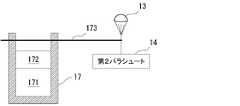
- the second pyrotechnic product 17forms a wire cutter that cuts the wire described above by activating the piston held in the cylindrical housing by the energy received from the igniter.
- FIG. 4is a diagram for explaining the configurations of the second pyrotechnic product 17, the first parachute 13, and the second parachute 14.
- FIG. The second pyrotechnic product 17includes an igniter 171 and a piston 172 in a cylindrical housing. A wire 173 is stretched in the moving direction of the piston 172 . Also, the wire 173 is connected to the parachute cord of the first parachute 13 and prevents the first parachute 13 from pulling out the second parachute 14 . The parachute cord of the first parachute 13 is connected to the top of the folded second parachute 14 .
- the third pyrotechnic product 18is also a pyrotechnic inflator (gas generator) containing an igniter inside, and feeds gas into the bag-like airbag 15 to inflate the airbag 15 .
- the warning device 19includes, for example, an LED or a speaker, and emits light or sound to inform the surroundings of the fall of the aircraft 2.
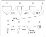
- FIG. 5is a diagram showing an example of how to fold a parachute.
- the shape of the canopy of the parachuteis not particularly limited, and shapes such as a hemispherical shape, a planar circular shape, a cross shape, and a hexagon shape can be adopted.
- (1) of FIG. 5is a view of the canopy folded in two in front view or side view. Then, as shown in (1) to (5) of FIG. 5, the canopy is horizontally divided into a plurality of equal parts (5 equal parts in the example of FIG. 5) when the canopy is opened, and folded into accordions. That is, from (1) to (5), the canopy folded in two is put together, and valley folds and mountain folds are alternately repeated along the fold line along the vertical direction when the umbrella is opened.
- the canopyis vertically divided into a plurality of equal parts (in the example of FIG. 5, divided into three equal parts) and folded into bellows. That is, from (5) to (7), valley folds and mountain folds are alternately repeated along folding lines along the horizontal direction when the umbrella is opened.
- the slings(lines) are put together.
- the slingsmay be wrapped, for example, in a circle.
- the first parachute 13 and the second parachute 14may be folded according to the procedure shown in FIG. 5, or may be folded by another existing method.
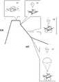
- FIG. 6is a processing flow diagram for explaining the operation of the safety device 1.
- FIG. FIG. 7is a diagram for explaining the altitude and elapsed time of the flying object 2 and the operation of the safety device 1. As shown in FIG. 7 correspond to the steps in FIG. The processing shown in FIG. 6 is executed by the safety device 1 while the aircraft 2 is in flight.
- the safety device 1includes a power supply unit (not shown) that supplies power to the sensor unit 11 and the control unit 12 described above, and operates independently of the aircraft 2 . That is, even if trouble occurs in the aircraft 2, the safety device 1 can operate independently.
- the control unit 12 of the safety device 1acquires data indicating the acceleration output by the acceleration sensor 111 (Fig. 6: S1).
- the acceleration sensor 111outputs observation values corresponding to acceleration in three axial directions at predetermined intervals.
- the control unit 12acquires the acceleration in the three-axis directions and calculates the synthetic acceleration of the three axes. Note that the control unit 12 may calculate the synthetic acceleration using the moving average of the acquired acceleration.
- control unit 12detects the fall of the flying object 2 using the acquired acceleration (FIG. 6: S2). In this step, if the data indicating the acceleration acquired in S1 indicates, for example, a vertical downward acceleration equal to or greater than a predetermined threshold value, the control unit 12 determines that the flying object 2 is falling. When the control unit 12 does not detect the drop in S2 (S2: NO), the process returns to S1 and repeats the process.
- control unit 12detects the fall in S2 (S2: YES)
- the control unit 12operates the first pyrotechnic product 16 to deploy the first parachute 13 (FIG. 6: S3).
- the control unit 12energizes the first pyrotechnic 16 to open the first parachute 13 connected to the weight 162 to be launched.
- the control unit 12may cause the alarm device 19 to output light or sound.
- control unit 12operates the third pyrotechnic product 18 at a predetermined timing to deploy the airbag 15 (FIG. 6: S4). In this step, the control unit 12 energizes the third pyrotechnic product 18 , ignites the igniter to generate gas, and inflates the airbag 15 .
- the timing of deploying the airbag 15is not particularly limited as long as it is before the aircraft 2 lands. .
- control unit 12acquires data indicating the atmospheric pressure output by the atmospheric pressure sensor 112, and calculates the altitude of the flying object 2 (FIG. 6: S5).
- the atmospheric pressure sensor 112outputs an observed value corresponding to atmospheric pressure at a predetermined cycle.
- the control unit 12calculates the altitude of the aircraft 2 using a known function that indicates the relationship between the measured value of air pressure and the altitude. Note that the control unit 12 may remove noise using a moving average of the obtained air pressure. Also, the control unit 12 may estimate the atmospheric pressure value using, for example, a Kalman filter.
- the control unit 12determines whether the altitude is equal to or less than a predetermined threshold (Fig. 6: S6). In this step, the control unit 12 determines whether the altitude calculated in S5 is equal to or less than a predetermined threshold. If it is determined in S6 that the altitude is not equal to or lower than the predetermined threshold (S6: NO), the process returns to S5 and repeats the process.
- the control unit 12operates the second pyrotechnic device 17 to deploy the second parachute 14 (FIG. 6: S7 ).
- the control unit 12energizes the second pyrotechnic product 17, and when the piston 172 cuts the wire 173, the second parachute 14 increases the air resistance of the first parachute 13. pulled out by and unfolds.
- the flying object 2can be landed at a place not so far from the initial flight path. Further, by deploying the second parachute 14 in S7, the impact of the landing of the flying object 2 can be sufficiently reduced.
- the aircraft 2can be landed at a position close to a predetermined flight route or delivery route, for example, by autopilot. can improve sexuality.
- the safety device 1 described abovecan be attached to various types of aircraft 2 . Further, for the above-described sequence control, such as the opening timing of the second parachute 14 and the deployment timing of the airbag 15 based on the above-described altitude threshold, preferable settings are defined in advance according to the type of the flying object 2, for example. , may be applied according to the type of the flying object 2.
- Safety device 11Sensor unit 111: Acceleration sensor 112: Air pressure sensor 12: Control unit 13: First parachute 14: Second parachute 15: Air bag 16: First pyrotechnic product 161: Ignitor 162: Weight 17: Second pyrotechnic 171: igniter 172: piston 173: wire 18: third pyrotechnic 19: alarm device 2: flying body
Landscapes
- Engineering & Computer Science (AREA)
- Aviation & Aerospace Engineering (AREA)
- Business, Economics & Management (AREA)
- Emergency Management (AREA)
- Mechanical Engineering (AREA)
- Remote Sensing (AREA)
- Emergency Lowering Means (AREA)
Abstract
Description
Translated fromJapanese本発明は、安全装置及び飛行体に関する。The present invention relates to a safety device and an aircraft.
従来、安全機構、駆動機構、射出機構および制御機構を備える飛行体用安全装置が提案されている(特許文献1)。また、エアバッグ装置の補助的な装置としてパラシュート装置を取り付けることができる小型飛行体も提案されている(特許文献2)。また、パラシュートにおいて結露が生じることを防止し、パラシュートをより確実に開傘させる技術も提案されている(特許文献3)。また、不具合検知部によって不具合が検知された場合、ドローンのプロペラの駆動を停止させ、パラシュートを射出したりエアバッグを作動させる技術も提案されている(特許文献4)。Conventionally, a safety device for an aircraft has been proposed that includes a safety mechanism, a drive mechanism, an injection mechanism, and a control mechanism (Patent Document 1). Also, a small flying object to which a parachute device can be attached as an auxiliary device for the airbag device has been proposed (Patent Document 2). Also, a technique has been proposed to prevent dew condensation from occurring in the parachute and open the parachute more reliably (Patent Document 3). There is also proposed a technique of stopping the driving of the propeller of the drone and ejecting a parachute or activating an airbag when a defect is detected by a defect detection unit (Patent Document 4).
飛行体の落下時、早期にパラシュートを開傘させると、飛行体が風に流され、予定されていた飛行ルートから大幅に外れた場所に着地するおそれがある。特に、いわゆるドローンのような無人飛行体を都市部で飛行させるような場合、緊急時であっても当初の飛行ルートにできるだけ近い位置に着地させることが望ましい。If the parachute is opened early when the flying object falls, the flying object may be swept away by the wind and land in a place significantly deviated from the planned flight route. In particular, when flying an unmanned flying object such as a so-called drone in an urban area, it is desirable to land as close as possible to the initial flight route even in an emergency.
そこで、本開示の技術は、飛行体の墜落時に着地点を制御し得る安全装置を提供することを目的とする。Therefore, the technology of the present disclosure aims to provide a safety device that can control the landing point when an aircraft crashes.
上記課題を解決するために、本開示では、安全装置は、飛行体に備え付けられる安全装置であって、落下速度を減衰させると共に飛行体の落下時の姿勢を制御する第1のパラシュートと、第1のパラシュートよりも遅く開傘させられ、飛行体の着地時の衝撃を低減させる第2のパラシュートと、飛行体の落下を検知するセンサ部と、第1のパラシュート及び第2のパラシュートの開傘を制御する制御部とを備える。また、制御部は、センサ部が落下を検知した後の第1のタイミングで、第1のパラシュートを開傘させると共に、第1のタイミングの後であって、さらに所定の条件を満たす第2のタイミングで、第2のパラシュートを開傘させる。In order to solve the above problems, in the present disclosure, the safety device is a safety device attached to a flying object, comprising a first parachute that attenuates the falling speed and controls the attitude of the flying object when it falls; A second parachute that is opened later than the first parachute and reduces the impact of landing of the flying object, a sensor unit that detects the falling of the flying object, and opening of the first and second parachutes. and a control unit for controlling the Further, the control unit causes the first parachute to open at a first timing after the sensor unit has detected the fall, and the control unit opens a second parachute that satisfies the predetermined condition after the first timing. At the right time, open the second parachute.
第1のパラシュートが開傘させられると、飛行体の落下速度を減衰すると共に飛行体の落下時の姿勢が制御される。このとき飛行体の着地時の衝撃を低減させるメインパラシュートである第2のパラシュートを開傘させてしまうと、例えば横風に流されて当初の飛行経路から大きく外れた場所に着地するおそれがある。上述のように、飛行体がさらに所定の条件を満たすまで第2のパラシュートは開傘させないように、飛行体の墜落時に着地点を制御すれば、当初の飛行経路からそれほど遠くない場所に飛行体を着地させ得る。すなわち、飛行体の墜落時に着地点を制御し得る。When the first parachute is opened, the falling speed of the flying object is attenuated and the attitude of the flying object when it falls is controlled. At this time, if the second parachute, which is the main parachute that reduces the landing impact of the flying object, is opened, there is a risk that the flying object will be swept away by a crosswind and land in a place greatly deviated from the initial flight path. As mentioned above, if the landing point is controlled when the vehicle crashes so that the secondary parachute will not deploy until the vehicle further meets a predetermined condition, the vehicle will land at a location not too far from its original flight path. can land. That is, the landing point can be controlled when the aircraft crashes.
また、第1のパラシュートを射出するための第1の火工品をさらに備え、制御部は、第1の火工品を制御することにより第1のパラシュートを開傘させるようにしてもよい。また、飛行体は、複数の回転翼を備えるマルチコプターであり、第1のパラシュートは、複数の回転翼と干渉しない方向に射出されるようにしてもよい。このようにすれば、パラシュートを確実に開傘させることができる。Further, a first pyrotechnic product for ejecting the first parachute may be further provided, and the control unit may open the first parachute by controlling the first pyrotechnic product. Also, the flying object may be a multicopter having a plurality of rotor blades, and the first parachute may be ejected in a direction that does not interfere with the plurality of rotor blades. In this way, the parachute can be reliably opened.
また、第1のパラシュートは、第2のパラシュートの傘頂部と接続され、第2のパラシュートの開傘を抑止するための抑止部と当該抑止部による抑止を解除する第2の火工品とをさらに備え、制御部は、第2の火工品を制御することにより第2のパラシュートを開傘させるようにしてもよい。また、抑止部は、第1のパラシュート又は第2のパラシュートと接続されるワイヤーを含み、第2の火工品は、発射体を射出してワイヤーを切断するワイヤーカッターであってもよい。例えばこのような構成により、第2のパラシュートを開傘するタイミングを制御し得る。Also, the first parachute is connected to the top of the second parachute, and comprises a restraining part for restraining the opening of the second parachute and a second pyrotechnic product for canceling restraint by the restraining part. In addition, the control unit may open the second parachute by controlling the second pyrotechnic product. The restraint may also include a wire connected to the first parachute or the second parachute, and the second pyrotechnic may be a wire cutter that shoots the projectile and cuts the wire. For example, with such a configuration, the timing of opening the second parachute can be controlled.
また、所定の条件は、飛行体の種別に応じて異なる条件を設定できるようにしてもよい。このようにすれば、安全装置を、様々な飛行体に容易に適用できる。Also, the predetermined condition may be set so that different conditions can be set according to the type of flying object. In this way, the safety device can be easily applied to various aircraft.
また、センサ部は、飛行体の高度をさらに測定し、所定の条件は、センサ部が測定した飛行体の高度が所定の閾値よりも低いことであってもよい。例えば、センサ部は気圧から高度を算出することができる。Also, the sensor unit may further measure the altitude of the flying object, and the predetermined condition may be that the altitude of the flying object measured by the sensor unit is lower than a predetermined threshold. For example, the sensor unit can calculate altitude from atmospheric pressure.
また、センサ部が落下を検知した場合に、音又は光を発する警報部をさらに備えるようにしてもよい。このようにすれば、飛行体の落下時に、周囲に警告できる。Also, an alarm unit that emits sound or light when the sensor unit detects a fall may be further provided. In this way, it is possible to warn the surroundings when the flying object falls.
また、センサ部が落下を検知した場合に、所定のタイミングで展開されるエアバッグをさらに備えるようにしてもよい。エアバッグにより、飛行体及び着地点付近の構造物等への衝撃をさらに抑えることができる。Also, an airbag that is deployed at a predetermined timing when the sensor unit detects a fall may be further provided. The airbag can further reduce the impact on the flying object and structures near the landing point.
また、センサ部及び制御部に給電する電力供給部をさらに備えるものであってもよい。このようにすれば、飛行体に異常が生じても、安全装置は単独で動作することができる。Also, a power supply unit that supplies power to the sensor unit and the control unit may be further provided. In this way, the safety device can operate independently even if an abnormality occurs in the flying object.
また、上述した安全装置を備える飛行体を提供することもできる。It is also possible to provide an aircraft equipped with the safety device described above.
本開示によれば、飛行体の墜落時に着地点を制御し得る安全装置を提供できる。According to the present disclosure, it is possible to provide a safety device that can control the landing point when an aircraft crashes.
以下に、図面を参照して本開示の実施形態に係る飛行体の安全装置について説明する。なお、実施形態における各構成及びそれらの組み合わせ等は、一例であって、本開示の主旨から逸脱しない範囲内で、適宜、構成の付加、省略、置換、及びその他の変更が可能である。本開示は、実施形態によって限定されることはなく、特許請求の範囲によってのみ限定される。A safety device for an aircraft according to an embodiment of the present disclosure will be described below with reference to the drawings. Note that each configuration and combination thereof in the embodiment is an example, and configuration addition, omission, replacement, and other changes are possible as appropriate without departing from the gist of the present disclosure. This disclosure is not limited by the embodiments, but only by the claims.
図1は、安全装置1及び飛行体2の一例を模式的に表す図である。また、図2は、安全装置1の一例を示す機能ブロック図である。本実施形態に係る安全装置1は、飛行体2の落下を検知し、パラシュート等を用いて着地又は着水時の飛行体2及び着地点付近の構造物等への衝撃を低減させる。飛行体2は、いわゆるドローンと呼ばれるような無人飛行機(UAV:Unmanned Aerial Vehicle)である。飛行体2は、例えば複数の回転翼を備えるマルチコプターであってもよい。また、飛行体2は、例えば、予め定められたルートを飛行して、荷物を配達するものであってもよいし、搭載するカメラで動画又は静止画を撮影するものであってもよい。FIG. 1 is a diagram schematically showing an example of a
安全装置1は、センサユニット11と、制御部12と、第1パラシュート13及び第2パラシュート14を格納するパラシュート格納部と、エアバッグ15と、パラシュートの開傘を制御する第1火工品16及び第2火工品17と、エアバッグ15の展開を制御する第3火工品18と、警報装置19とを含む。センサユニット11は、飛行体2の落下を検知するための加速度センサ111と、飛行体2の高度を算出するための気圧センサ112とを含む。また、センサユニット11は、飛行体2の重心近傍に装着される。The
制御部12は、マイクロコントローラのようなプロセッサであり、センサユニット11や、火工品16~18、警報装置19と信号線を介して接続されている。そして、制御部12は、センサユニット11の出力に基づいて安全装置1の制御を行う。なお、制御部12は、センサユニット11内に設けられてもよい。The
第1パラシュート13は、パイロットシュートであり、第2パラシュート14は、メインパラシュートである。すなわち、第1パラシュート13のパラシュートコードは第2パラシュート14の傘頂部に接続され、第1パラシュート13の空気抵抗力によって第2パラシュート14が引き出される。ただし、本実施形態では、第2パラシュート14の開傘を抑止するための抑止部を備え、第1パラシュート13と第2パラシュート14とは、それぞれ制御部12の制御に応じたタイミングで開傘するようになっている。具体的には、第1パラシュート13は、抑止部として機能するワイヤーを介して例えばパラシュート格納部に接続される。そして、ワイヤーは、切断されるまで、第1パラシュート13が第2パラシュート14を引き出すことを抑止する。The
また、エアバッグ15は、飛行体2の下部に装着され、着地又は着水の衝撃を軽減する。エアバッグ15は、自動車などに搭載されている公知のエアバッグ装置で使用しているものを使用することができる。なお、エアバッグ15はガスを排出するためのベント口は有しない方が、着水時に飛行体2を長時間浮かせることができるため好ましい。また、エアバッグ15の膨張展開後の形状は特に制限されるものではなく、飛行体2の構造および形状に応じて適宜選択することができる。例えば、球状、扁球状(円板状)、平面視において楕円状の扁平な球状、多面体状、なす形状、棒状、浮き輪状、舟形、又はこれらのエアバッグが1箇所以上で複数接続される形状(例えば、ヨットの双胴艇や三胴艇のような形状)等にすることができる。Also, the
第1火工品16は、筒状の筐体から、第1パラシュート13の傘頂部と接続された錘を、点火器から受けるエネルギーによりスラグ弾のように発射するガンスラグを形成する。図3は、第1火工品16、第1パラシュート13及び第2パラシュート14の構成を説明するための図である。第1火工品16は、シリンダ状の筐体に、点火器161と錘162とを備える。また、錘162は、折り畳まれた第1パラシュート13の傘頂部に接続されている。そして、図示していない抵抗体に通電させ、点火器161に点火されることにより発生するガス圧により、錘162が発射されると、錘162と接続された第1パラシュート13が引き出され、開傘する。なお、第1火工品16は飛行体2の上部に取り付けられ、錘は飛行体2の回転翼と干渉しない方向に発射される。The first pyrotechnic 16 forms a gun slug that fires a weight connected to the top of the
第2火工品17は、筒状の筐体内に保持するピストンを点火器から受けるエネルギーにより作動させ、上述したワイヤーを切断するワイヤーカッターを形成する。図4は、第2火工品17、第1パラシュート13及び第2パラシュート14の構成を説明するための図である。第2火工品17は、シリンダ状の筐体に、点火器171とピストン172とを備える。また、ピストン172の移動方向にはワイヤー173が張られている。また、ワイヤー173は、第1パラシュート13のパラシュートコードに接続され、第1パラシュート13が第2パラシュート14を引き出すことを抑止する。なお、第1パラシュート13のパラシュートコードは、折り畳まれた第2パラシュート14の傘頂部に接続されている。そして、図示していない抵抗体に通電させ、点火器171に点火されることにより発生するガス圧により、ピストン172が移動すると、ワイヤー173を切断し、第1パラシュート13と接続された第2パラシュート14は、第1パラシュート13の空気抵抗力によって引き出され、開傘する。The second
第3火工品18も、内部に点火器を含む火薬式のインフレータ(ガス発生器)であり、袋状のエアバッグ15内にガスを送り込み、エアバッグ15を膨張させる。The third
警報装置19は、例えばLED又はスピーカーを含み、光又は音を発して周囲に飛行体2の落下を知らせる。The
図5は、パラシュートの畳み方の一例を示す図である。パラシュートのキャノピーの形状は特に限定されず、半球型、平面円形型、十字型、ヘキサゴン型等の形状を採用することができる。図5の(1)は、キャノピーを正面視又は側面視した形状に2つ折りにした図である。そして、図5の(1)から(5)に示すように、キャノピーは開傘時の水平方向に複数に等分(図5の例では5等分)され、蛇腹折りにされる。すなわち、(1)から(5)までは、2つ折りにされたキャノピーを合わせて、開傘時の鉛直方向に沿った折り線に沿って、谷折りと山折りとが交互に繰り返される。さらに、図5の(5)から(7)に示すように、キャノピーは開傘時の鉛直方向に複数に等分(図5の例では3等分)され、蛇腹折りにされる。すなわち、(5)から(7)までは、開傘時の水平方向に沿った折り線に沿って、谷折りと山折りとが交互に繰り返される。最後に、図5の(7)から(8)に示すように、吊索(ライン)をまとめる。吊索は、例えば円形に巻いてまとめるようにしてもよい。第1パラシュート13及び第2パラシュート14は、図5に示す手順で折り畳むようにしてもよいし、他の既存の手法により折り畳むようにしてもよい。FIG. 5 is a diagram showing an example of how to fold a parachute. The shape of the canopy of the parachute is not particularly limited, and shapes such as a hemispherical shape, a planar circular shape, a cross shape, and a hexagon shape can be adopted. (1) of FIG. 5 is a view of the canopy folded in two in front view or side view. Then, as shown in (1) to (5) of FIG. 5, the canopy is horizontally divided into a plurality of equal parts (5 equal parts in the example of FIG. 5) when the canopy is opened, and folded into accordions. That is, from (1) to (5), the canopy folded in two is put together, and valley folds and mountain folds are alternately repeated along the fold line along the vertical direction when the umbrella is opened. Further, as shown in (5) to (7) of FIG. 5, the canopy is vertically divided into a plurality of equal parts (in the example of FIG. 5, divided into three equal parts) and folded into bellows. That is, from (5) to (7), valley folds and mountain folds are alternately repeated along folding lines along the horizontal direction when the umbrella is opened. Finally, as shown in (7) to (8) of FIG. 5, the slings (lines) are put together. The slings may be wrapped, for example, in a circle. The
図6は、安全装置1の動作を説明するための処理フロー図である。また、図7は、飛行体2の高度及び経過時間、並びに安全装置1の動作を説明するための図である。なお、図7に示す符号は、図6の工程と対応している。図6に示す処理は、飛行体2の飛行中に、安全装置1が実行する。なお、安全装置1は、上述したセンサユニット11や制御部12に給電する電力供給部(図示せず)を備え、飛行体2からは独立して動作する。すなわち、飛行体2にトラブルが生じた場合も、安全装置1は単独で動作することができる。FIG. 6 is a processing flow diagram for explaining the operation of the
安全装置1の制御部12は、加速度センサ111が出力する加速度を示すデータを取得する(図6:S1)。加速度センサ111は、所定の周期で3軸方向の加速度に応じた観測値をそれぞれ出力する。一方、制御部12は、3軸方向の加速度を取得し、3軸の合成加速度を算出する。なお、制御部12は、取得した加速度の移動平均を用いて合成加速度を算出するようにしてもよい。The
また、制御部12は、取得した加速度を用いて飛行体2の落下を検知する(図6:S2)。本ステップでは、S1において取得した加速度を示すデータが、例えば鉛直下方へ向かう所定の閾値以上の加速度を示す場合、制御部12は飛行体2が落下していると判断する。S2において制御部12が落下を検知しない場合(S2:NO)、S1に戻って処理を繰り返す。Also, the
一方、S2において制御部12が落下を検知した場合(S2:YES)、制御部12は第1火工品16を動作させ、第1パラシュート13を展開させる(図6:S3)。本ステップでは、図3を用いて説明したように、制御部12は第1火工品16に通電させ、発射される錘162に接続された第1パラシュート13を開傘させる。また、S2において制御部12が落下を検知した後に、制御部12は、警報装置19に光又は音を出力させるようにしてもよい。On the other hand, if the
また、制御部12は、所定のタイミングで第3火工品18を動作させ、エアバッグ15を展開させる(図6:S4)。本ステップでは、制御部12は第3火工品18に通電させ、点火器に点火してガスを発生させ、エアバッグ15を膨張させる。なお、エアバッグ15を展開させるタイミングは、飛行体2の着地前であれば特に限定されず、例えばS3の処理から所定時間後であってもよいし、後述するS7と同時であってもよい。Also, the
また、制御部12は、気圧センサ112が出力する気圧を示すデータを取得し、飛行体2の高度を算出する(図6:S5)。気圧センサ112は、所定の周期で気圧に応じた観測値を出力する。一方、制御部12は、気圧の測定値と高度との関係を示す既知の関数を用いて飛行体2の高度を算出する。なお、制御部12は、取得した気圧の移動平均を用いてノイズを除去するようにしてもよい。また、制御部12は、例えばカルマンフィルターを用いて気圧の値を推定するようにしてもよい。Also, the
そして、制御部12は、高度が所定の閾値以下であるか判断する(図6:S6)。本ステップでは、制御部12は、S5で算出された高度が予め定められた閾値以下であるか判断する。S6において高度が所定の閾値以下でないと判断された場合(S6:NO)、S5に戻って処理を繰り返す。Then, the
一方、S6において高度が所定の閾値以下であると判断された場合(S6:YES)、制御部12は、第2火工品17を動作させ、第2パラシュート14を展開させる(図6:S7)。本ステップでは、図4を用いて説明したように、制御部12は第2火工品17に通電させ、ピストン172がワイヤー173を切断すると、第2パラシュート14は第1パラシュート13の空気抵抗力によって引き出され、開傘する。On the other hand, if it is determined in S6 that the altitude is equal to or lower than the predetermined threshold (S6: YES), the
<効果>
図7に示すように、S3において第1パラシュート13が開傘させられると、飛行体2の落下速度を減衰すると共に飛行体2の落下時の姿勢が制御される。このときメインパラシュートである第2パラシュート14を開傘させてしまうと、例えば横風に流されて当初の飛行経路から大きく外れた場所に着地するおそれがある。すなわち、周囲の建造物や電線、通行人などに接触する可能性が高まる。本実施形態では、飛行体2が所定の高度以下に降下するまで第2パラシュート14は開傘させられないため、飛行体の墜落時に着地点を制御し得る。すなわち、第1パラシュート13とは異なるタイミングで、第2パラシュート14を開傘させるよう制御することで、当初の飛行経路からそれほど遠くない場所に飛行体2を着地させ得る。また、S7において第2パラシュート14を展開することにより、飛行体2の着地時の衝撃を十分に低減させることができる。<effect>
As shown in FIG. 7, when the
したがって、本実施形態に係る安全装置1によれば、例えば自動操縦によりあらかじめ定められた飛行ルートや配達ルートに近い位置に飛行体2を着地させることができ、飛行体2の墜落時においても安全性を向上させることができる。また、飛行体が運搬する荷物や、飛行体に搭載されるカメラ等の機器を保護することができる。Therefore, according to the
<その他>
上述した安全装置1は、様々な種類の飛行体2に取り付けることができる。また、上述した高度の閾値に基づく第2パラシュート14の開傘タイミングや、エアバッグ15の展開タイミング等、上述したシーケンス制御は、例えば飛行体2の種別に応じて予め好ましい設定を定義しておき、飛行体2の種別に応じて適用できるようにしてもよい。<Others>
The
以上、本開示に係る電流回路遮断装置の実施形態および変形例について説明したが、上述した各実施形態および変形例は可能な限り組み合わせることができる。また、例えばエアバッグ15や、警報装置19等、図2に示した構成の一部は、本開示の趣旨を逸脱しない範囲で削除することができる。Although the embodiments and modifications of the current circuit breaker according to the present disclosure have been described above, the embodiments and modifications described above can be combined as much as possible. Also, part of the configuration shown in FIG. 2, such as the
1:安全装置
11:センサユニット
111:加速度センサ
112:気圧センサ
12:制御部
13:第1パラシュート
14:第2パラシュート
15:エアバッグ
16:第1火工品
161:点火器
162:錘
17:第2火工品
171:点火器
172:ピストン
173:ワイヤー
18:第3火工品
19:警報装置
2:飛行体1: Safety device 11: Sensor unit 111: Acceleration sensor 112: Air pressure sensor 12: Control unit 13: First parachute 14: Second parachute 15: Air bag 16: First pyrotechnic product 161: Ignitor 162: Weight 17: Second pyrotechnic 171: igniter 172: piston 173: wire 18: third pyrotechnic 19: alarm device 2: flying body
Claims (12)
Translated fromJapanese落下速度を減衰させると共に前記飛行体の落下時の姿勢を制御する第1のパラシュートと、
前記第1のパラシュートよりも遅く開傘させられ、前記飛行体の着地時の衝撃を低減させる第2のパラシュートと、
前記飛行体の落下を検知するセンサ部と、
前記第1のパラシュート及び前記第2のパラシュートの開傘を制御する制御部と、
を備え、
前記制御部は、前記センサ部が落下を検知した後の第1のタイミングで、前記第1のパラシュートを開傘させると共に、前記第1のタイミングの後であって、さらに所定の条件を満たす第2のタイミングで、前記第2のパラシュートを開傘させる
安全装置。A safety device mounted on an aircraft,
a first parachute that attenuates the falling speed and controls the attitude of the flying object when it falls;
a second parachute that is opened later than the first parachute and reduces impact when the flying object lands;
a sensor unit that detects the falling of the flying object;
a control unit that controls opening of the first parachute and the second parachute;
with
The control section causes the first parachute to open at a first timing after the sensor section detects the fall, and a second timing that satisfies a predetermined condition after the first timing. A safety device that opens the second parachute at the timing of 2.
前記制御部は、前記第1の火工品を制御することにより前記第1のパラシュートを開傘させる
請求項1に記載の安全装置。further comprising a first pyrotechnic for ejecting the first parachute;
The safety device according to claim 1, wherein the control unit opens the first parachute by controlling the first pyrotechnic product.
前記第1のパラシュートは、前記複数の回転翼と干渉しない方向に射出される
請求項2に記載の安全装置。The flying object is a multicopter equipped with a plurality of rotor blades,
The safety device according to claim 2, wherein the first parachute is ejected in a direction that does not interfere with the plurality of rotor blades.
前記第2のパラシュートの開傘を抑止するための抑止部と当該抑止部による抑止を解除する第2の火工品とをさらに備え、
前記制御部は、前記第2の火工品を制御することにより前記第2のパラシュートを開傘させる
請求項1から3のいずれか一項に記載の安全装置。The first parachute is connected to the canopy of the second parachute,
further comprising a deterrent part for deterring opening of the second parachute and a second pyrotechnic product for releasing deterrence by the deterrent part;
The safety device according to any one of claims 1 to 3, wherein the control unit opens the second parachute by controlling the second pyrotechnic product.
前記第2の火工品は、発射体を射出して前記ワイヤーを切断するワイヤーカッターである
請求項4に記載の安全装置。The deterrent includes a wire connected to the first parachute or the second parachute,
5. The safety device of claim 4, wherein the second pyrotechnic device is a wire cutter that shoots a projectile to cut the wire.
請求項1から5のいずれか一項に記載の安全装置。The safety device according to any one of claims 1 to 5, wherein different conditions can be set for the predetermined condition according to the type of the flying object.
前記所定の条件は、前記センサ部が測定した前記飛行体の高度が所定の閾値よりも低いことである
請求項1から6のいずれか一項に記載の安全装置。The sensor unit further measures the altitude of the flying object,
The safety device according to any one of claims 1 to 6, wherein the predetermined condition is that the altitude of the flying object measured by the sensor section is lower than a predetermined threshold.
請求項1から7のいずれか一項に記載の安全装置。The safety device according to any one of claims 1 to 7, further comprising an alarm unit that emits sound or light when the sensor unit detects a fall.
請求項1から8のいずれか一項に記載の安全装置。The safety device according to any one of claims 1 to 8, further comprising an airbag that deploys at a predetermined timing when the sensor section detects a fall.
請求項9に記載の安全装置。The safety device according to claim 9, wherein the airbag does not have a vent port for discharging gas.
請求項1から10のいずれか一項に記載の安全装置。The safety device according to any one of claims 1 to 10, further comprising a power supply unit that supplies power to the sensor unit and the control unit.
Priority Applications (3)
| Application Number | Priority Date | Filing Date | Title |
|---|---|---|---|
| CN202280011843.4ACN116867707A (en) | 2021-02-02 | 2022-01-31 | Safety device and flying body |
| EP22749665.0AEP4289727A4 (en) | 2021-02-02 | 2022-01-31 | SAFETY DEVICE AND AIRCRAFT |
| US18/228,944US20230373666A1 (en) | 2021-02-02 | 2023-08-01 | Safety device and flight vehicle |
Applications Claiming Priority (2)
| Application Number | Priority Date | Filing Date | Title |
|---|---|---|---|
| JP2021015136AJP7580288B2 (en) | 2021-02-02 | 2021-02-02 | Safety devices and flying vehicles |
| JP2021-015136 | 2021-02-02 |
Related Child Applications (1)
| Application Number | Title | Priority Date | Filing Date |
|---|---|---|---|
| US18/228,944ContinuationUS20230373666A1 (en) | 2021-02-02 | 2023-08-01 | Safety device and flight vehicle |
Publications (1)
| Publication Number | Publication Date |
|---|---|
| WO2022168793A1true WO2022168793A1 (en) | 2022-08-11 |
Family
ID=82741349
Family Applications (1)
| Application Number | Title | Priority Date | Filing Date |
|---|---|---|---|
| PCT/JP2022/003597CeasedWO2022168793A1 (en) | 2021-02-02 | 2022-01-31 | Safety device and flight vehicle |
Country Status (5)
| Country | Link |
|---|---|
| US (1) | US20230373666A1 (en) |
| EP (1) | EP4289727A4 (en) |
| JP (1) | JP7580288B2 (en) |
| CN (1) | CN116867707A (en) |
| WO (1) | WO2022168793A1 (en) |
Families Citing this family (1)
| Publication number | Priority date | Publication date | Assignee | Title |
|---|---|---|---|---|
| CN114502463B (en)* | 2021-06-16 | 2025-01-03 | 深圳市大疆创新科技有限公司 | Control method and device of unmanned aerial vehicle system, unmanned aerial vehicle system and storage medium |
Citations (11)
| Publication number | Priority date | Publication date | Assignee | Title |
|---|---|---|---|---|
| US3079113A (en)* | 1960-10-04 | 1963-02-26 | Jr Andre J Meyer | Vehicle parachute and equipment jettison system |
| JPH0415499A (en)* | 1990-05-08 | 1992-01-20 | Mitsubishi Heavy Ind Ltd | Object dropping device |
| US20030197095A1 (en)* | 2001-12-07 | 2003-10-23 | Daniel Preston | Steerable parachute control system and method |
| JP2007182182A (en)* | 2006-01-10 | 2007-07-19 | Ihi Aerospace Co Ltd | Return member recovery method and recovery device for high speed return |
| JP2010018264A (en)* | 2008-06-09 | 2010-01-28 | Technical Research & Development Institute Ministry Of Defence | Parachute mounting device |
| JP2018001814A (en) | 2016-06-28 | 2018-01-11 | 株式会社Ksf | Parachute and aircraft with parachute system |
| JP2018034761A (en) | 2016-09-02 | 2018-03-08 | 株式会社ダイセル | Small aircraft with airbag device |
| JP2018154249A (en) | 2017-03-17 | 2018-10-04 | 東芝電波プロダクツ株式会社 | Drone safety device and method and drone |
| JP2018193055A (en)* | 2017-05-16 | 2018-12-06 | 日本化薬株式会社 | Expand device of parachute or paraglider, and flying object therewith |
| WO2019039062A1 (en) | 2017-08-24 | 2019-02-28 | 日本化薬株式会社 | Flight vehicle safety device and flight vehicle |
| CN212243847U (en)* | 2019-12-31 | 2020-12-29 | 深圳市天鹰装备科技有限公司 | Umbrella rope cutter and control circuit |
Family Cites Families (4)
| Publication number | Priority date | Publication date | Assignee | Title |
|---|---|---|---|---|
| US11459113B2 (en)* | 2016-07-11 | 2022-10-04 | Kitty Hawk Corporation | Multimodal aircraft recovery system |
| US10577111B2 (en)* | 2016-10-28 | 2020-03-03 | Kitty Hawk Corporation | Bimodal parachute deployment system |
| TWI610852B (en)* | 2016-12-20 | 2018-01-11 | Aircraft parachute device | |
| JP2020104803A (en)* | 2018-12-28 | 2020-07-09 | キヤノンマーケティングジャパン株式会社 | Unmanned aircraft, method for controlling unmanned aircraft and program |
- 2021
- 2021-02-02JPJP2021015136Apatent/JP7580288B2/enactiveActive
- 2022
- 2022-01-31CNCN202280011843.4Apatent/CN116867707A/enactivePending
- 2022-01-31WOPCT/JP2022/003597patent/WO2022168793A1/ennot_activeCeased
- 2022-01-31EPEP22749665.0Apatent/EP4289727A4/enactivePending
- 2023
- 2023-08-01USUS18/228,944patent/US20230373666A1/ennot_activeAbandoned
Patent Citations (11)
| Publication number | Priority date | Publication date | Assignee | Title |
|---|---|---|---|---|
| US3079113A (en)* | 1960-10-04 | 1963-02-26 | Jr Andre J Meyer | Vehicle parachute and equipment jettison system |
| JPH0415499A (en)* | 1990-05-08 | 1992-01-20 | Mitsubishi Heavy Ind Ltd | Object dropping device |
| US20030197095A1 (en)* | 2001-12-07 | 2003-10-23 | Daniel Preston | Steerable parachute control system and method |
| JP2007182182A (en)* | 2006-01-10 | 2007-07-19 | Ihi Aerospace Co Ltd | Return member recovery method and recovery device for high speed return |
| JP2010018264A (en)* | 2008-06-09 | 2010-01-28 | Technical Research & Development Institute Ministry Of Defence | Parachute mounting device |
| JP2018001814A (en) | 2016-06-28 | 2018-01-11 | 株式会社Ksf | Parachute and aircraft with parachute system |
| JP2018034761A (en) | 2016-09-02 | 2018-03-08 | 株式会社ダイセル | Small aircraft with airbag device |
| JP2018154249A (en) | 2017-03-17 | 2018-10-04 | 東芝電波プロダクツ株式会社 | Drone safety device and method and drone |
| JP2018193055A (en)* | 2017-05-16 | 2018-12-06 | 日本化薬株式会社 | Expand device of parachute or paraglider, and flying object therewith |
| WO2019039062A1 (en) | 2017-08-24 | 2019-02-28 | 日本化薬株式会社 | Flight vehicle safety device and flight vehicle |
| CN212243847U (en)* | 2019-12-31 | 2020-12-29 | 深圳市天鹰装备科技有限公司 | Umbrella rope cutter and control circuit |
Also Published As
| Publication number | Publication date |
|---|---|
| EP4289727A4 (en) | 2024-11-20 |
| CN116867707A (en) | 2023-10-10 |
| US20230373666A1 (en) | 2023-11-23 |
| JP2022118547A (en) | 2022-08-15 |
| JP7580288B2 (en) | 2024-11-11 |
| EP4289727A1 (en) | 2023-12-13 |
Similar Documents
| Publication | Publication Date | Title |
|---|---|---|
| JP7232374B2 (en) | flying object | |
| US11267573B2 (en) | Small flying vehicle equipped with airbag device | |
| WO2018190319A1 (en) | Flight vehicle and method for controlling flight vehicle | |
| EP4063273B1 (en) | Emergency landing of aircraft | |
| US12222717B2 (en) | Automated aircraft recovery system | |
| JP7191090B2 (en) | Actuating device for flying object, method for preventing malfunction of operating device for flying object, thrust generating device for flying object, deploying device for parachute or paraglider, and airbag device | |
| EP3589543B1 (en) | Aircraft provided with a secondary flight assembly | |
| US11919650B2 (en) | Multimodal aircraft recovery system | |
| US10981657B2 (en) | Multi-rocket parachute deployment system | |
| CN114423681A (en) | Damage mitigation for aircraft with deployable parachutes | |
| US20230373666A1 (en) | Safety device and flight vehicle | |
| JP6644119B1 (en) | Airbag device and unmanned aerial vehicle equipped with the same | |
| JP2023109122A (en) | Linear connector for flying object, safety device, flying object equipped with safety device, and tying method using linear connecting device for flying object | |
| NZ749620B (en) | Multi-rocket parachute deployment system |
Legal Events
| Date | Code | Title | Description |
|---|---|---|---|
| 121 | Ep: the epo has been informed by wipo that ep was designated in this application | Ref document number:22749665 Country of ref document:EP Kind code of ref document:A1 | |
| WWE | Wipo information: entry into national phase | Ref document number:202280011843.4 Country of ref document:CN | |
| NENP | Non-entry into the national phase | Ref country code:DE | |
| ENP | Entry into the national phase | Ref document number:2022749665 Country of ref document:EP Effective date:20230904 |