WO2022168609A1 - Control system, motion planning device, control device, motion planning and control method, motion planning method, and control method - Google Patents
Control system, motion planning device, control device, motion planning and control method, motion planning method, and control methodDownload PDFInfo
- Publication number
- WO2022168609A1 WO2022168609A1PCT/JP2022/001839JP2022001839WWO2022168609A1WO 2022168609 A1WO2022168609 A1WO 2022168609A1JP 2022001839 WJP2022001839 WJP 2022001839WWO 2022168609 A1WO2022168609 A1WO 2022168609A1
- Authority
- WO
- WIPO (PCT)
- Prior art keywords
- data
- trajectory
- unit
- assembly
- state transition
- Prior art date
- Legal status (The legal status is an assumption and is not a legal conclusion. Google has not performed a legal analysis and makes no representation as to the accuracy of the status listed.)
- Ceased
Links
Images


Classifications
- B—PERFORMING OPERATIONS; TRANSPORTING
- B25—HAND TOOLS; PORTABLE POWER-DRIVEN TOOLS; MANIPULATORS
- B25J—MANIPULATORS; CHAMBERS PROVIDED WITH MANIPULATION DEVICES
- B25J9/00—Programme-controlled manipulators
- B25J9/10—Programme-controlled manipulators characterised by positioning means for manipulator elements
- B—PERFORMING OPERATIONS; TRANSPORTING
- B25—HAND TOOLS; PORTABLE POWER-DRIVEN TOOLS; MANIPULATORS
- B25J—MANIPULATORS; CHAMBERS PROVIDED WITH MANIPULATION DEVICES
- B25J9/00—Programme-controlled manipulators
- B25J9/16—Programme controls
- B25J9/1656—Programme controls characterised by programming, planning systems for manipulators
Definitions
- the present disclosurerelates to a control system, motion planning device, control device, motion planning and control method, motion planning method, and control method.
- Patent Document 1Japanese Patent Application Laid-Open No. 2019-209446. This technique analyzes the adjacency relationship of the component parts using a predetermined analysis method according to the part type, and generates the assembly order of the component parts.
- Patent Document 3International Publication No. 2015/177855
- components that can be disassembledare identified from an assembly
- edgesare drawn between the nodes that are geometrically constrained using the components as nodes, and an evaluation value is assigned to each of the nodes and edges.
- the decomposition graphis generated, the decomposition order of the assembly is determined using the decomposition graph, and the assembly order is generated.
- Non-Patent Document 1Dmitry Kalashnikov, et al. "QT-Opt: Scalable Deep Reinforcement Learning for Vision-Based Robotic Manipulation " arXiv preprint arXiv:1806.10293, 2018.).
- a techniquehas been proposed in which a robot learns the motion of gripping an object based on image data obtained from a camera through reinforcement learning. According to this method, at least a part of a series of processes for teaching the robot to grasp an object can be automated.
- Patent Document 4JP-A-2020-082332.
- the series that realizes the final target relative amountis determined from the relative amount at the time when the motion control is started, and the relative amount is changed to the relative amount in the target state to which the next transition occurs.
- a control commandis generated to allow
- the present disclosurehas been made in view of the above circumstances, and aims to provide a control system, an operation planning method, and a control method for appropriately and efficiently managing the work process of a robot and executing the control of the robot. aim.
- a further objectis to provide a motion planning device and a control device suitable for constructing such a control system.
- a control systemis a control system including a motion planning device and a control device, wherein the motion planning device is a first element that is a part or an assembly and a part or an assembly A transition for creating first unit state transition data representing a transition from a state in which a second element exists independently to a state in which a third element, which is an assembly composed of the first element and the second element, is assembled.
- a grip data identifierthat identifies certain first grip data
- a final portion of the relative trajectory of the first element and the second element for performing the transitionthe final portion of the relative trajectory of the first element and the second element a guide trajectory creation unit that creates a first guide trajectory serving as a common target relative trajectory irrespective of the initial relative position
- the control devicecontrols the first unit state transition data, the first gripping data, and the first an acquisition unit that acquires one guide trajectory and acquires from a first sensor first observation data obtained by observing the position of the first element and the position of the second element; and the first observation data and the first grip data.
- a motion planning deviceis a state in which a first element that is a part or an assembly and a second element that is a part or an assembly exist independently from the first element and the second element.
- a transition creation unitthat creates first unit state transition data representing a transition to a state in which the third element, which is an assembled body, is assembled;
- a gripping data specifying unitthat specifies first gripping data that is a planned value of the relative positions of the end effector and the first gripping object when gripping the first element or the second element; creating a first guide trajectory which is the final part of the relative trajectory of the first element and the second element and which is a common target relative trajectory regardless of the initial relative positions of the first element and the second element; and a guide trajectory generator.
- a control deviceis a state in which a first element that is a part or an assembly and a second element that is a part or an assembly exist independently of each other.
- First unit state transition datarepresenting a transition to a state in which the third element that is an assembly is assembled, and the end effector of the robot for assembly is the first element or the second element that is the first grasped object and a final relative trajectory of the first element and the second element for performing the transition.
- a first guide trajectorythat is a common target relative trajectory irrespective of the initial relative positions of the first element and the second element, and obtains the position of the first element and the position of the second element an acquisition unit that acquires first observation data obtained by observing a position from a first sensor; an acquisition unit that causes the end effector to grip the first gripping target based on the first observation data and the first gripping data;
- the first grasped objectwhich is one of the first element and the second element, relative to the other element along a target relative trajectory including a guide trajectory in the final part, the first an execution unit for executing a first task of completing the state in which the third element is assembled in the unit state transition data.
- control systemmotion planning and control method, it is possible to appropriately and efficiently manage the work process of the robot and control the robot.
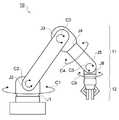
- FIG. 1is a diagram showing a schematic configuration of a robot as an example of an object to be controlled;
- FIG.It is a block diagram which shows the hardware constitutions of a motion planning apparatus and a control apparatus.
- 3is a block diagram showing an example of functional configurations of a motion planning device and a control device;
- FIG.It is a figure which shows an example of the unit state transition data produced in a motion planning apparatus.
- FIG. 4is a diagram showing an example of an assembly procedure and a disassembly procedure using parts A to D;
- FIG. 5is a diagram showing an example of relative positions of grip data;
- 5is a diagram showing an example of relative positions of grip data; It is an example of relative trajectories recorded when an assembly of parts AD is disassembled into an assembly of parts D and parts AC. It is a figure which shows an example of a guide track
- FIG. 1is a diagram showing the configuration of a control system for controlling a robot according to this embodiment.
- the control system 1has a robot 10 , a state observation sensor 14 , a motion planning device 20 , a state transition control section 25 and a control device 30 .
- the state transition control unit 25may be part of the operation planning device 20, may be part of the control device 30, or may be a part of the operation planning device 20 and the control device 30 as in the present embodiment. may be configured as an independent device from any of
- FIGS. 2 and 3are diagrams showing a schematic configuration of a robot 10 as an example of a controlled object.
- the robot 10 in this embodimentis a 6-axis vertical articulated robot, and an end effector 12 is provided at the tip 11a of the arm 11 .
- the robot 10grips the parts by the end effector 12 and performs assembly work of the assembly.
- the end effector 12is configured to have a pair of holding parts 12a of hands, but the end effector 12 may be used as a suction pad to suck a component.
- the term "holding a component"includes sucking the component.
- the robot 10has an arm 11 with 6 degrees of freedom with joints J1 to J6.
- the joints J1 to J6connect the links so as to be rotatable in the directions of arrows C1 to C6 by motors (not shown).
- a gripperis connected as an end effector 12 to the tip of the arm 11 .
- a vertical articulated robotis taken as an example, but a horizontal articulated robot (scalar robot) may be used.
- a 6-axis robothas been exemplified, a multi-joint robot with other degrees of freedom such as a 5-axis or 7-axis robot, or a parallel link robot may be used.
- the state observation sensor 14observes the state of the robot 10 and outputs observed data as state observation data.
- a joint encoder of the robot 10for example, a visual sensor (camera), a motion capture, a force-related sensor, or the like is used.
- the position and orientation of the tip 11a of the arm 11can be identified from the angles of the joints, and the orientation of the part (work target) can be estimated from the visual sensor and/or the force-related sensor.
- a motion capture markeris attached to the end effector 12
- the position and orientation of the end effector 12can be identified as the state of the robot 10, and the orientation of the part (workpiece) can be determined from the position and orientation of the end effector 12. can be estimated.
- Force-related sensoris a general term for force sensors and torque sensors, and also includes tactile sensors when sensors are provided in areas that come into contact with parts.
- a force-related sensormay be provided on the surface of the part where the end effector 12 grips the part or on the joint inside the end effector 12 so as to detect the force that the end effector of the robot 10 receives from the part.
- a force-related sensoris, for example, a sensor that detects a single-element or multi-element, single-axis, three-axis, or six-axis force as the state of the robot 10 . By using the force-related sensor, it is possible to accurately grasp how the end effector 12 grips the part, that is, the posture of the part, and to perform appropriate control.
- the visual sensorcan also detect the position and orientation of the end effector 12 itself and the part gripped by the end effector 12 as the state of the robot 10 .
- State observation sensor 14is an example of a first sensor.
- the first sensormay be one sensor, or may be a generic term for sensors when the sensor that observes the first element and the sensor that observes the second element are different from each other.
- the state observation sensor 14is an example of a second sensor. The second sensor may be the same sensor as the first sensor.
- FIG. 3is a block diagram showing the hardware configuration of the motion planning device 20 and the control device 30 according to this embodiment.
- the motion planning device 20 and the control device 30can be implemented with similar hardware configurations.
- the operation planning device 20includes a CPU (Central Processing Unit) 20A, a ROM (Read Only Memory) 20B, a RAM (Random Access Memory) 20C, a storage 20D, an input section 20E, a display section 20F, and a communication interface (I/F) 20G. have Each component is communicably connected to each other via a bus 20H.
- the control device 30has a CPU 30A, a ROM 30B, a RAM 30C, a storage 30D, an input section 30E, a display section 30F, and a communication I/F 30G. Each component is communicably connected to each other via a bus 30H.
- the case of the motion planning device 20will be described below.
- programsare stored in the ROM 20B or the storage 20D.
- the CPU 20Ais a central processing unit that executes various programs and controls each configuration. That is, the CPU 20A reads a program from the ROM 20B or the storage 20D and executes the program using the RAM 20C as a work area. The CPU 20A performs control of each configuration and various arithmetic processing according to programs recorded in the ROM 20B or the storage 20D.
- the ROM 20Bstores various programs and various data.
- the RAM 20Ctemporarily stores programs or data as a work area.
- the storage 20Dis configured by a HDD (Hard Disk Drive), SSD (Solid State Drive), or flash memory, and stores various programs including an operating system and various data.
- the input unit 20Eincludes a keyboard and a pointing device such as a mouse, and is used for various inputs.
- the display unit 20Fis, for example, a liquid crystal display, and displays various information.
- the display unit 20Fmay employ a touch panel system and function as the input unit 20E.
- the communication interface (I/F) 20Gis an interface for communicating with other devices, and uses standards such as Ethernet (registered trademark), FDDI, or Wi-Fi (registered trademark), for example.
- FIG. 4is a block diagram showing an example of the functional configuration of the motion planning device 20 and the control device 30. As shown in FIG. Note that the motion planning device 20 and the control device 30 may be integrated.
- the motion planning device 20has a transition creating unit 110, a grasping data specifying unit 112, and a guide trajectory creating unit 114 as functional configurations.
- Each functional configuration of the operation planning device 20is realized by the CPU 20A reading a program stored in the ROM 20B or the storage 20D, developing it in the RAM 20C, and executing it.
- the control device 30has an acquisition unit 130 and an execution unit 132 as functional configurations.
- Each functional configuration of the control device 30is realized by the CPU 30A reading a program stored in the ROM 30B or the storage 30D, developing it in the RAM 30C, and executing it.
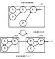
- FIG. 5is a diagram showing an example of unit state transition data created in the motion planning device 20.
- the assembly process by the work of the robot 10is represented by a state transition diagram.
- an entire state transition diagram 201is decomposed into individual parts or assemblies, and the data representing the element transitions are represented as unit state transition data (202A and 202B).
- the unit state transition datais a partial element of the composite state transition data including each of the unit state transition data.
- the operation planning device 20prepares each unit state transition data as an operation plan, and accepts registration information necessary for preparing the unit state transition data by input from the user.
- the registration informationincludes various types of information such as part information (part ID, type, etc.), CAD information for each type of end effector 12, assembly procedure (including disassembly procedure), and part gripping position (including orientation).
- the assembly procedureincludes relative trajectories of parts recorded during assembly (or disassembly) on the simulation.
- the transition creation unit 110creates composite state transition data that includes each piece of unit state transition data in a form that is linked by mutual common elements. Each unit state transition data is created from the assembly procedure in the registration information.
- the transition creating unit 110creates a third element A′, which is an assembly composed of the first element and the second element, from the state in which the first element A and the second element B exist independently.
- the first unit state transition data 202Arepresenting the transition to the state where the A first element A is a part or assembly.
- the second component Bis also a component or assembly.
- the transition creation unit 110creates the next second unit state transition data 202B using the third element A'.
- the second unit state transition data 202Brepresents unit state transition data indicating the next assembly process after the transition to the assembled state of the third element A' of the first unit state transition data 202A.
- the transition creation unit 110creates a state in which the third element A′ and the fourth element C exist independently, and the fifth element A′′, which is an assembly composed of the third element A′ and the fourth element C, is assembled.
- the second unit state transition data 202B representing the transition to the existing stateis created.
- the composite state transition data 201 created by the transition creating unit 110is composed of the first unit state transition data 202A and the second unit state transition data 202B by the third element A′, which is a common element of the first unit state transition data 202A and the second unit state transition data 202B. It has a format in which unit state transition data 202B is linked.
- unit state transition data 202Ais the first unit state transition data in the above description, which unit state transition data is the first unit state transition data is optional.
- the unit state transition data 202Bmay be the first unit state transition data, and the next unit state transition data may be the second unit state transition data.
- the second unit state transition datais data representing creation of a new assembly element by combining the elements assembled by the transition represented by the first unit state transition data with other elements.
- the transition creation unit 110may create only the unit state transition data 202A and 202B without creating the composite state transition data 201.
- FIG. 6is a diagram showing an example of an assembly procedure and a disassembly procedure using parts A to D.
- FIG. 6When applied to state transitions, each of (1) to (4) corresponds to unit state transition data, and data in the form of connecting all the steps of (1) to (4) corresponds to composite state transition data. Applying the work process of assembling part A and part B in (1) to the above-mentioned first unit state transition data, part A and part B correspond to the first element and the second element, respectively, and part A and part B corresponds to the third element. (2) to (4) can also be applied to the first unit state transition data.
- the assembly of parts A and Bcorresponds to the third element
- the part Ccorresponds to the fourth element
- the assembly of parts A to Ccorresponds to the fifth element.
- (3) and (4)can also be applied to the second unit state transition data.
- the gripping data identification unit 112 and the guide trajectory creation unit 114will be described below using the procedure for assembling parts A to D as an example.
- the gripped data identifying unit 112identifies gripped data for each piece of unit state transition data based on the gripped position of the part in the registration information.
- the gripping datais a planned value of the relative positions of the end effector and the gripped object when the end effector 12 of the robot 10 grips the gripped object for assembly.
- the gripped data specifying unit 112specifies first gripped data when the end effector 12 grips the first element or the second element, which is the first gripped object. Also, the gripped data specifying unit 112 specifies the second gripped data when the end effector 12 of the robot 10 grips the third element or the fourth element, which is the second gripped object.
- the relative position in grip datawill be described below.
- the other element for the element that is the grasped objectis the integration target object.
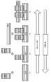
- FIG. 7is a diagram showing an example of relative positions of grip data.
- the relative position R1 of the end effector 12 with respect to the component Ais indicated by an arrow when the end effector 12 is a suction pad.
- FIG. 7Ashows the relative position R1 of the end effector 12 with respect to the component A when the end effector 12 is a suction pad.
- FIG. 7Bshows the relative position R2 of the end effector 12 with respect to the part B when the end effector 12 is a gripper (hand) having a pair of holding portions.
- Part C and part Dare represented similarly.
- the relative positionis obtained by the following formula (1).
- (T obj ⁇ tcp ) ⁇ 1T tcp ⁇ obj (1)
- the left siderepresents the component coordinate system
- the right siderepresents the relative position (position and orientation) from the end effector 12 .
- the gripping datais calculated, for example, as a planned value of the target relative position between the CAD data with identification ID of the end effector 12 used at the time of gripping and the target to be gripped.
- the planned value of the relative positionmay be entered by the user who is the administrator including it in the gripping position of the part (the position to be gripped on the part surface) in the registration information, or it can be automatically performed by existing methods such as gripping planning. may be calculated.
- the guide trajectory creation unit 114creates a guide trajectory for each piece of unit state transition data based on the assembly procedure included in the registration information.
- the guide trajectoryis the final part of the relative trajectory of the element that is the grasp object and the element that is the destination object for state transition, and is the common target relative position between these elements regardless of the initial relative position. It is a trajectory that is considered a trajectory.
- a guide trajectory creation unit 114creates a first guide trajectory for assembling the first element and the second element. Also, the guide trajectory creating unit 114 creates a second guide trajectory for assembling the third element and the fourth element.
- the trajectorymay be represented by the velocity information without explicitly including the position information. When a trajectory is represented by velocity information, it is represented by a vector quantity including direction information.
- the first guide trajectoryis the first part of the relative trajectory of the first element and the second element recorded when the third element is decomposed into the first element and the second element, or from the first element and the second element It can be created as the final portion of the relative trajectory of the first and second elements recorded when the third element was assembled.
- An example of a method for creating a guide trajectorywill be described below.
- FIG. 8is an example of a relative trajectory recorded when an assembly of parts A to D is disassembled into an assembly of parts D and parts A to C. That is, for the first part of the relative trajectory of the first and second elements recorded when the third element is resolved.
- FIG. 8shows the relative trajectory G1 of the component D, and the opposite trajectory of the relative trajectory G1 can be used as a guide trajectory when the component D is gripped and assembled.
- Such a relative trajectorymay be calculated when generating a procedure for decomposing from the target state.
- a bounding box (BB)is set for each process, and when the bounding box no longer overlaps the moved parts during disassembly, the disassembly of the process is terminated.
- FIG. 9is a diagram showing an example of a guide trajectory.
- FIG. 9Ashows the guide trajectory (G2) when the part A is gripped and lifted.
- FIG. 9Bshows the guide trajectory (G3) when installing part B on part A.
- FIG. 9Ashows the guide trajectory (G2) when the part A is gripped and lifted.
- FIG. 9Bshows the guide trajectory (G3) when installing part B on part A.
- the state transition control unit 25acquires composite state transition data or unit state transition data, grip data and guide trajectory from the motion planning device 20 .
- the state transition control unit 25acquires composite state transition data, it decomposes it into unit state transition data.
- state transition control unit 25receives notification from control device 30 that execution of one state transition is completed, state transition control unit 25 instructs control device 30 to execute the next state transition.
- the state transition control unit 25provides the unit state transition data, the grip data, and the guide trajectory to the control device 30 collectively in advance or each time the state transition is performed so that the control device 30 can use the unit state transition data, the grip data, and the guide trajectory for executing the state transition. do.
- the state transition control unit 25may be included in the motion planning device 20, may be included in the control device 30, or may be a device different from any of them. Further, the entire control system including the operation planning device 20, the control device 30 and the state transition control section 25 may be one device.
- each processing unit of the control device 30will be described using the state transition in FIG. 5 as an example.
- one state transitionis called a task.
- the acquisition unit 130acquires the unit state transition data 202A (first unit state transition data) and corresponding grip data (first grip data) and guide trajectory (first guide trajectory) from the state transition control unit 25. . Further, the acquisition unit 130 acquires observation data (first observation data) obtained by observing the position of the element A (first element) and the position of the element B (second element) from the state observation sensor 14 (first sensor). . Note that the position of element A and the position of element B include attitudes. According to the progress of the task, the acquisition unit 130 obtains the unit state transition data 202B (second unit state transition data), the corresponding grip data (second grip data), and the guide trajectory (second guide trajectory) for state transition. Acquired from the control unit 25 . The acquisition unit 130 acquires observation data (second observation data) obtained by observing the position of the element A' (third element) and the position of the element C (fourth element) from the state observation sensor 14 (second sensor).
- the execution unit 132uses the unit state transition data 202A output from the state transition control unit 25 to execute the task (first task) that is the state transition represented by the unit state transition data 202A. Specifically, the execution unit 132 causes the end effector 12 to grip the gripping object (first gripping object) that is one of the elements A and B based on the observation data and gripping data for the elements A and B. and move the grasped object relative to the other element along the target relative trajectory including the guide trajectory in the final part.
- the execution unit 132grasps the positions of element A and element B in the robot coordinate system from observation data. Assuming that the element A is grasped, the starting position of the guide trajectory in the robot coordinate system is grasped from the position of the element B and the guide trajectory. The movement amount of the robot 10 to the starting point of the guide trajectory is calculated, and the end effector 12 grips the element A based on the grip data. The element A gripped by the end effector 12 is moved to the start position of the guide trajectory and then moved along the guide trajectory.
- the execution unit 132may execute the above operation by appropriately correcting the observation error, the gripping position error, and the direction error between the robot coordinate system and the guide trajectory.
- the execution unit 132moves the grasped object, which is one of the elements A and B, from its initial position to the start position of the guide trajectory or any position on the guide trajectory relative to the other element. Generate a transition trajectory.
- the trajectory ST from gripping the component B to the start position of the guide trajectory G3is an example of the relative trajectory.
- the transition trajectorymay be either a relative trajectory or a trajectory in the robot coordinate system.
- the element that is not grippedis basically assumed to be fixed as an object to be built, but it may be gripped by the end effector 12 of another robot 10 and moved. In addition, if movement occurs due to contact between parts during the task, observation may be performed again.
- FIG. 10is a sequence diagram showing the processing flow of the control system 1 of this embodiment.
- the CPU 20Afunctions as each unit of the operation planning device 20 to perform the operation planning process
- the CPU 30Afunctions as each unit of the control device 30 to perform control processing.
- step S100the motion planning device 20 creates composite state transition data and control data by connecting each unit state transition data.
- the control dataare each gripping data and each guide trajectory corresponding to each created unit state transition data. Details of the processing in step S100 will be described later.
- step S102the action planning device 20 outputs the composite state transition data and the control data to the state transition control section 25.
- the state transition control unit 25divides the composite state transition data into unit state transition data.
- step S104the state transition control unit 25 accepts the task start instruction and starts the task to be processed.
- the task start instructionis received, the first task to be processed is started, and the task to be processed is updated according to the progress of the task.
- the task start instructionmay be received by the control device 30 .
- step S106the state transition control unit 25 notifies the control device 30 of task start.
- step S108the state transition control unit 25 outputs unit state transition data corresponding to the task to be processed and control data corresponding to the unit state transition data to the control device 30.
- step S110when the acquisition unit 130 of the control device 30 receives the task start notification, it acquires observation data observed by the state observation sensor 14.
- step S112the execution unit 132 of the control device 30 calculates the transition trajectory of the robot 10 to the starting point position of the guide trajectory based on the observation data and grip data.
- step S114the execution unit 132 of the control device 30 executes the task to be processed. That is, the end effector 12 grips the element to be gripped based on the gripping data, and moves the gripped object relative to the other element along the calculated transfer trajectory and guide trajectory.
- step S116the execution unit 132 of the control device 30 determines whether or not the end point of the guide trajectory has been reached in executing the task. If it is determined that the end point has been reached, the process proceeds to step S118, and if it is determined that the end point has not been reached, the determination of step 116 is repeated.
- step S118the execution unit 132 of the control device 30 notifies the state transition control unit 25 of task completion.
- step S120the state transition control unit 25 determines whether or not processing has been completed up to the final state of the composite state transition data. If it is determined that the process has been completed up to the final state, the process proceeds to step S124. If it is determined that the processing has not ended up to the final state, the process proceeds to step S122.
- step S122the state transition control unit 25 updates the task to be processed, and returns to step S108. Updating a task is a process of advancing a task to be processed to the next task.
- step S108after updating the task, the unit state transition data and control data (grasping data and guide trajectory) corresponding to the task to be processed are output to the control device 30, and the subsequent processes are repeated.
- step S124the state transition control unit 25 ends the task and ends the processing of the control system 1.
- FIG. 11is a flow chart showing the flow of the motion planning process of the motion planning device 20 in step S100.
- step S200the CPU 20A accepts registration information by input from the user.
- the registration informationincludes various information such as part information (part ID, type, etc.), CAD information for each type of end effector 12, assembly procedure, and part grip position (including orientation).
- step S202the transition creation unit 110 creates composite state transition data by concatenating each unit state transition data based on the assembly procedure in the registration information.
- step S204the gripping data identifying unit 112 identifies gripping data based on the gripping position of the part in the registration information for each piece of unit state transition data.
- step S206the guide trajectory creation unit 114 creates a guide trajectory for each unit state transition data based on the assembly procedure (recorded relative trajectory of the parts) in the registration information.
- step S208the CPU 20A displays each of the created unit state transition data, grip data, and guide trajectory on the display section 20F.
- the displayhere is not limited to the display section 20F, and may be performed via another device.
- step S210the CPU 20A determines whether or not a correction instruction has been received from the user. If it is determined that the correction instruction has been received, the process proceeds to step S212, and if it is determined that the correction instruction has not been received, the process proceeds to step S102.
- step S212the CPU 20A reflects the content of the correction instruction on each of the unit state transition data, the grip data, and the guide trajectory.
- the correction instructionincludes, for example, correction of each state transition diagram of the unit state transition data, addition of a waypoint, correction of the grasping position of the part of the grasping data, correction of the relative trajectory in the guide trajectory, and the like.
- the composite state transition data including each of the final unit state transition data, and the control data including the grip data and the guide trajectoryare output to the state transition control section 25.
- composite state transition data and control dataare created by concatenating each unit state transition data, and tasks are controlled by the unit state transition data. Thereby, the work process of the robot can be managed appropriately and efficiently.
- the operation planning process or control process executed by the CPU reading the software (program) in the above embodimentmay be executed by various processors other than the CPU.
- the processoris a PLD (Programmable Logic Device) whose circuit configuration can be changed after manufacturing, such as an FPGA (Field-Programmable Gate Array), and an ASIC (Application Specific Integrated Circuit) to execute specific processing.
- a dedicated electric circuit or the likewhich is a processor having a specially designed circuit configuration, is exemplified.
- the motion planning process or control processmay be executed by one of these various processors, or by a combination of two or more processors of the same or different kind (e.g., multiple FPGAs, and a CPU and an FPGA). , etc.).
- the hardware structure of these various processorsis an electric circuit in which circuit elements such as semiconductor elements are combined.
- the programis pre-stored (installed) in the ROM 20B (30B) or the storage 20D (30D), but the present invention is not limited to this.
- the programmay be provided in a form recorded on a recording medium such as CD-ROM (Compact Disk Read Only Memory), DVD-ROM (Digital Versatile Disk Read Only Memory), and USB (Universal Serial Bus) memory.
- the programmay be downloaded from an external device via a network.
- robot system10 robot 11 arm 12 gripper 14 state observation sensor 20 motion planning device 25 state transition control section 30 control device
Landscapes
- Engineering & Computer Science (AREA)
- Robotics (AREA)
- Mechanical Engineering (AREA)
- Manipulator (AREA)
Abstract
Description
Translated fromJapanese本開示は、制御システム、動作計画装置、制御装置、動作計画及び制御方法、動作計画方法、並びに制御方法に関する。The present disclosure relates to a control system, motion planning device, control device, motion planning and control method, motion planning method, and control method.
製品の組み立て作業に必要な部品は多種多様であり、製品の製造工程では、これらの多種多様な部品の性質等を考慮して組み立て手順を作成する必要がある。このような背景から、部品の組み立て手順の作成に関する技術が提案されている。There are a wide variety of parts required for product assembly work, and in the product manufacturing process, it is necessary to create an assembly procedure that takes into consideration the properties of these diverse parts. In view of this background, techniques have been proposed for creating part assembly procedures.
例えば、部品種別を考慮して組み立て順序を生成するための技術がある(特許文献1:特開2019-209446号公報参照)。この技術では、部品種別に応じた所定の解析方法を用いて構成部品の隣接関係を解析し、構成部品の組立順序を生成している。For example, there is a technique for generating an assembly order in consideration of part types (see Patent Document 1: Japanese Patent Application Laid-Open No. 2019-209446). This technique analyzes the adjacency relationship of the component parts using a predetermined analysis method according to the part type, and generates the assembly order of the component parts.
また、把持する部品との適合性を考慮した適切なハンド選択作業のティーチングを自動化するための技術がある(特許文献2:国際公開第2015/178377号参照)。この技術では、部品に関する情報を格納した部品情報DBと、一又は複数のハンドに関する情報を格納したハンド情報DBとを用いて、部品を把持するハンドを選択するティーチング情報を生成して、組み立て時間を最小化するようにハンドの選択を最適化している。In addition, there is a technique for automating the teaching of an appropriate hand selection task considering the compatibility with the gripped part (see Patent Document 2: International Publication No. 2015/178377). In this technique, a part information DB storing information about parts and a hand information DB storing information about one or more hands are used to generate teaching information for selecting a hand that grips a part, thereby shortening assembly time. It optimizes hand selection to minimize
また、適切な組立順序を生成するための技術がある(特許文献3:国際公開第2015/177855号参照)。この技術では、組立品の中から分解可能な構成部品を特定し、構成部品をノードとして、幾何学的拘束関係にある該ノード間にエッジを張り、ノード及びエッジの各々に評価値を付与した分解グラフを生成し、分解グラフを用いて組立品の分解順序を決定し、組立順序を生成している。There is also a technique for generating an appropriate assembly order (see Patent Document 3: International Publication No. 2015/177855). In this technique, components that can be disassembled are identified from an assembly, edges are drawn between the nodes that are geometrically constrained using the components as nodes, and an evaluation value is assigned to each of the nodes and edges. The decomposition graph is generated, the decomposition order of the assembly is determined using the decomposition graph, and the assembly order is generated.
また、組み立て作業を行うロボットの動作生成に関する技術がある。There are also technologies related to motion generation for robots that perform assembly work.
例えば、機械学習を利用して、遂行する作業をロボットに習得させる手法が研究されている(非特許文献1:Dmitry Kalashnikov, et al. "QT-Opt: Scalable Deep Reinforcement Learning for Vision-Based Robotic Manipulation" arXiv preprint arXiv:1806.10293, 2018.参照)。この技術では、カメラから得られる画像データに基づいて対象物を把持する動作を強化学習によりロボットに習得させる手法が提案されている。この手法によれば、対象物を把持する動作をロボットに教示する一連の処理の少なくとも一部を自動化することができる。For example, research is being conducted on a method of using machine learning to make a robot learn the work to be performed (Non-Patent Document 1: Dmitry Kalashnikov, et al. "QT-Opt: Scalable Deep Reinforcement Learning for Vision-Based Robotic Manipulation " arXiv preprint arXiv:1806.10293, 2018.). In this technology, a technique has been proposed in which a robot learns the motion of gripping an object based on image data obtained from a camera through reinforcement learning. According to this method, at least a part of a series of processes for teaching the robot to grasp an object can be automated.
また、汎用性をもつ制御装置に係る技術がある(特許文献4:特開2020-082332号公報参照)。この技術では、動作の制御を開始する時点における相対関係量から最終目標の相対関係量を実現する系列を決定する等を行い、相対関係量を次に遷移する目標の状態における相対関係量に変化させるように制御指令を生成している。There is also a technology related to a versatile control device (see Patent Document 4: JP-A-2020-082332). In this technology, the series that realizes the final target relative amount is determined from the relative amount at the time when the motion control is started, and the relative amount is changed to the relative amount in the target state to which the next transition occurs. A control command is generated to allow
もっとも、上述した組み立て手順の作成に関する技術は、あくまで作業の流れを示した手順書を作成する手法であり、ロボットがどのように動作して部品を組み立てるのか等は考慮していない。そのため、ロボットの動作を考慮して組み立て手順を作成する手法が求められる。However, the technology related to the creation of the assembly procedure described above is just a method of creating a procedure manual that shows the work flow, and does not consider how the robot will operate to assemble the parts. Therefore, there is a need for a method of creating an assembly procedure in consideration of robot motions.
また、上述したロボットの動作生成に関する技術は、機械学習を導入した場合の欠点として、ロボットを管理する管理者の意図した動作を適切に反映できない場合が想定される。例えば、機械学習で学習したモデルにより生成した動作が管理者の意図した動作と異なる場合、モデルを意図した動作を生成するように再学習させるには手間とコストが掛かるため変更が困難である。また、同じ動作であっても、作業意図が異なることがある。また、入力と出力が一対一の対応にならないことがある。よって一意にロボットの動作生成ができるわけではない。また、機械学習では一作業一学習でモデルを学習する場合が多いものの、実際には複数の作業の組み合わせの中から作業の各々の条件が管理者によって与えられる場合が多い。そのため、これらの多数の条件付けを考慮して予めモデルを学習しておくことは困難である。In addition, it is assumed that the above-mentioned technology related to robot motion generation cannot appropriately reflect the intended motion of the administrator who manages the robot as a drawback when machine learning is introduced. For example, if the behavior generated by a machine-learned model differs from the behavior intended by the administrator, re-learning the model to generate the intended behavior would be time-consuming and costly, making it difficult to change. Also, even if the action is the same, the work intention may be different. Also, there may not be a one-to-one correspondence between inputs and outputs. Therefore, it is not possible to uniquely generate the motion of the robot. In addition, in machine learning, a model is often learned by learning one task at a time, but in reality, there are many cases in which conditions for each task are given by a manager from a combination of a plurality of tasks. Therefore, it is difficult to pre-learn the model considering these many conditionings.
よって、工程ごとのロボットの動作計画の管理を管理者が容易に行えるような組み立て手順が作成されることが望ましい。また、作成された手順のデータを用いてロボットの動作が制御されることが望ましい。Therefore, it is desirable to create an assembly procedure that allows administrators to easily manage robot motion plans for each process. In addition, it is desirable to control the motion of the robot using the created procedure data.
本開示は、上記事情を鑑みてなされたものであり、ロボットの作業工程を適切かつ効率的に管理しロボットの制御を実行するための制御システム、並びに動作計画方法及び制御方法を提供することを目的とする。さらに、そのような制御システムを構成するために好適な動作計画装置及び制御装置を提供することを目的とする。The present disclosure has been made in view of the above circumstances, and aims to provide a control system, an operation planning method, and a control method for appropriately and efficiently managing the work process of a robot and executing the control of the robot. aim. A further object is to provide a motion planning device and a control device suitable for constructing such a control system.
本開示の第1態様に係る制御システムは、動作計画装置と、制御装置とを含む制御システムであって、前記動作計画装置は、部品又は組み立て体である第1要素と部品又は組み立て体である第2要素とが独立に存在する状態から前記第1要素及び前記第2要素からなる組み立て体である第3要素が組み立てられている状態への遷移を表す第1単位状態遷移データを作成する遷移作成部、組み立てのためにロボットのエンドエフェクタが第1把持対象物である前記第1要素又は前記第2要素を把持したときの前記エンドエフェクタ及び前記第1把持対象物の相対位置の計画値である第1把持データを特定する把持データ特定部、及び、前記遷移を行うための前記第1要素及び前記第2要素の相対軌道の最終部分であって、前記第1要素及び前記第2要素の初期相対位置にかかわらない共通の目標相対軌道とされる第1ガイド軌道を作成するガイド軌道作成部、を含み、前記制御装置は、前記第1単位状態遷移データ、前記第1把持データ及び前記第1ガイド軌道を取得し、前記第1要素の位置及び前記第2要素の位置を観測した第1観測データを第1センサから取得する取得部、及び、前記第1観測データ及び前記第1把持データに基づいて前記エンドエフェクタにより前記第1把持対象物を把持させ、前記第1ガイド軌道を最終部分に含む目標相対軌道に沿って前記第1要素及び前記第2要素の一方である前記第1把持対象物を他方の要素に対して相対的に移動させることにより、前記第1単位状態遷移データにおいて前記第3要素が組み立てられた状態を完成させる第1タスクを実行する実行部、を含む。A control system according to a first aspect of the present disclosure is a control system including a motion planning device and a control device, wherein the motion planning device is a first element that is a part or an assembly and a part or an assembly A transition for creating first unit state transition data representing a transition from a state in which a second element exists independently to a state in which a third element, which is an assembly composed of the first element and the second element, is assembled. A planning value of the relative positions of the end effector and the first gripped object when the end effector of the robot grips the first element or the second element, which is the first gripped object, for assembly. a grip data identifier that identifies certain first grip data; and a final portion of the relative trajectory of the first element and the second element for performing the transition, the final portion of the relative trajectory of the first element and the second element a guide trajectory creation unit that creates a first guide trajectory serving as a common target relative trajectory irrespective of the initial relative position, wherein the control device controls the first unit state transition data, the first gripping data, and the first an acquisition unit that acquires one guide trajectory and acquires from a first sensor first observation data obtained by observing the position of the first element and the position of the second element; and the first observation data and the first grip data. and gripping the first gripping object by the end effector based on the first gripping that is one of the first element and the second element along a target relative trajectory including the first guide trajectory in the final part an execution unit that performs a first task of completing the assembled state of the third element in the first unit state transition data by moving an object relative to the other element.
本開示の第2態様に係る動作計画装置は、部品又は組み立て体である第1要素と部品又は組み立て体である第2要素とが独立に存在する状態から前記第1要素及び前記第2要素からなる組み立て体である第3要素が組み立てられている状態への遷移を表す第1単位状態遷移データを作成する遷移作成部と、組み立てのためにロボットのエンドエフェクタが第1把持対象物である前記第1要素又は前記第2要素を把持したときの前記エンドエフェクタ及び前記第1把持対象物の相対位置の計画値である第1把持データを特定する把持データ特定部と、前記遷移を行うための前記第1要素及び前記第2要素の相対軌道の最終部分であって、前記第1要素及び前記第2要素の初期相対位置にかかわらない共通の目標相対軌道とされる第1ガイド軌道を作成するガイド軌道作成部と、を含む。A motion planning device according to a second aspect of the present disclosure is a state in which a first element that is a part or an assembly and a second element that is a part or an assembly exist independently from the first element and the second element. a transition creation unit that creates first unit state transition data representing a transition to a state in which the third element, which is an assembled body, is assembled; a gripping data specifying unit that specifies first gripping data that is a planned value of the relative positions of the end effector and the first gripping object when gripping the first element or the second element; creating a first guide trajectory which is the final part of the relative trajectory of the first element and the second element and which is a common target relative trajectory regardless of the initial relative positions of the first element and the second element; and a guide trajectory generator.
本開示の第3態様に係る制御装置は、部品又は組み立て体である第1要素と部品又は組み立て体である第2要素とが独立に存在する状態から前記第1要素及び前記第2要素からなる組み立て体である第3要素が組み立てられている状態への遷移を表す第1単位状態遷移データ、組み立てのためにロボットのエンドエフェクタが第1把持対象物である前記第1要素又は前記第2要素を把持したときの前記エンドエフェクタ及び前記第1把持対象物の相対位置の計画値である第1把持データ、並びに、前記遷移を行うための前記第1要素及び前記第2要素の相対軌道の最終部分であって、前記第1要素及び前記第2要素の初期相対位置にかかわらない共通の目標相対軌道とされる第1ガイド軌道、を取得し、前記第1要素の位置及び前記第2要素の位置を観測した第1観測データを第1センサから取得する取得部と、前記第1観測データ及び前記第1把持データに基づいて前記エンドエフェクタにより前記第1把持対象物を把持させ、前記第1ガイド軌道を最終部分に含む目標相対軌道に沿って前記第1要素及び前記第2要素の一方である前記第1把持対象物を他方の要素に対して相対的に移動させることにより、前記第1単位状態遷移データにおいて前記第3要素が組み立てられた状態を完成させる第1タスクを実行する実行部と、を含む。A control device according to a third aspect of the present disclosure is a state in which a first element that is a part or an assembly and a second element that is a part or an assembly exist independently of each other. First unit state transition data representing a transition to a state in which the third element that is an assembly is assembled, and the end effector of the robot for assembly is the first element or the second element that is the first grasped object and a final relative trajectory of the first element and the second element for performing the transition. a first guide trajectory that is a common target relative trajectory irrespective of the initial relative positions of the first element and the second element, and obtains the position of the first element and the position of the second element an acquisition unit that acquires first observation data obtained by observing a position from a first sensor; an acquisition unit that causes the end effector to grip the first gripping target based on the first observation data and the first gripping data; By moving the first grasped object, which is one of the first element and the second element, relative to the other element along a target relative trajectory including a guide trajectory in the final part, the first an execution unit for executing a first task of completing the state in which the third element is assembled in the unit state transition data.
開示の制御システム、並びに動作計画及び制御方法によれば、ロボットの作業工程を適切かつ効率的に管理しロボットの制御を実行することができる。According to the disclosed control system, motion planning and control method, it is possible to appropriately and efficiently manage the work process of the robot and control the robot.
以下、本開示の実施形態の一例を、図面を参照しつつ説明する。なお、各図面において同一又は等価な構成要素及び部分には同一の参照符号を付与している。また、図面の寸法比率は、説明の都合上誇張されており、実際の比率とは異なる場合がある。An example of an embodiment of the present disclosure will be described below with reference to the drawings. In each drawing, the same or equivalent components and portions are given the same reference numerals. Also, the dimensional ratios in the drawings are exaggerated for convenience of explanation, and may differ from the actual ratios.
図1は、本実施形態に係るロボットを制御するための制御システムの構成を示す図である。図1に示すように、制御システム1は、ロボット10と、状態観測センサ14と、動作計画装置20と、状態遷移制御部25と、制御装置30とを有する。なお、状態遷移制御部25は、動作計画装置20の一部であってもよいし、制御装置30の一部であってもよいし、本実施形態のように動作計画装置20及び制御装置30のいずれからも独立した装置として構成されていてもよい。FIG. 1 is a diagram showing the configuration of a control system for controlling a robot according to this embodiment. As shown in FIG. 1 , the
(ロボット)
図2及び図3は、制御対象の一例としてのロボット10の概略構成を示す図である。本実施形態におけるロボット10は、6軸垂直多関節ロボットであり、アーム11の先端11aにエンドエフェクタ12が設けられる。ロボット10は、エンドエフェクタ12によって部品を把持して組み立て体の組立作業を行う。図3の例ではエンドエフェクタ12は1組の挟持部12aのハンドを有する構成としているが、エンドエフェクタ12を吸着パッドとして、部品を吸着するようにしてもよい。本明細書においては、部品を吸着することも含めて部品を把持するという。(robot)
2 and 3 are diagrams showing a schematic configuration of a
図2に示すように、ロボット10は、関節J1~J6を備えた6自由度のアーム11を有する。各関節J1~J6は、図示しないモータによりリンク同士を矢印C1~C6の方向に回転可能に接続する。アーム11の先端にはエンドエフェクタ12としてグリッパが接続されている。ここでは、垂直多関節ロボットを例に挙げたが、水平多関節ロボット(スカラーロボット)であってもよい。また、6軸ロボットを例に挙げたが、5軸や7軸などその他の自由度の多関節ロボットであってもよく、パラレルリンクロボットであってもよい。As shown in FIG. 2, the
(状態観測センサ)
状態観測センサ14は、ロボット10の状態を観測し、観測したデータを状態観測データとして出力する。状態観測センサ14としては、例えば、ロボット10の関節のエンコーダ、視覚センサ(カメラ)、モーションキャプチャ、力関連センサ等が用いられる。ロボット10の状態として、各関節の角度からアーム11の先端11aの位置及び姿勢が特定でき、視覚センサ及び/又は力関連センサから部品(作業対象物)の姿勢が推定できる。モーションキャプチャ用のマーカーがエンドエフェクタ12に取り付けられている場合には、ロボット10の状態としてエンドエフェクタ12の位置及び姿勢が特定でき、エンドエフェクタ12の位置及び姿勢から部品(作業対象物)の姿勢が推定できる。(state observation sensor)
The
力関連センサとは、力覚センサ及びトルクセンサの総称であり、さらにセンサを部品と接触する部位に設ける場合には触覚センサも含む総称である。力関連センサは、ロボット10のエンドエフェクタが部品から受ける力を検出するように、エンドエフェクタ12が部品を把持する部分の表面や、エンドエフェクタ12内の関節部分に設けてもよい。力関連センサは、例えば、1要素または多要素の、1軸、3軸、又は6軸の力をロボット10の状態として検出するセンサである。力関連センサを用いることで、エンドエフェクタ12が部品をどのように把持しているか、すなわち部品の姿勢をより精度良く把握でき、適切な制御が可能となる。"Force-related sensor" is a general term for force sensors and torque sensors, and also includes tactile sensors when sensors are provided in areas that come into contact with parts. A force-related sensor may be provided on the surface of the part where the
また、視覚センサによっても、エンドエフェクタ12自体やエンドエフェクタ12が把持している部品の位置及び姿勢をロボット10の状態として検出できる。The visual sensor can also detect the position and orientation of the
このように、状態観測センサ14である各種センサによって、エンドエフェクタ12、及び把持されている部品についての状態を検出することができる。また、各種センサの検出結果を状態観測データとして取得することができる。状態観測センサ14が、第1センサの一例である。また、第1センサは、1つのセンサでもよく、第1要素を観測するセンサと第2要素を観測するセンサが互いに異なる場合のセンサの総称であってもよい。また、状態観測センサ14が、第2センサの一例である。第2センサは第1センサと同一のセンサであってもよい。In this way, various sensors that are the
(動作計画装置/制御装置)
次に、動作計画装置20及び制御装置30の構成について説明する。(Motion planning device/control device)
Next, configurations of the
図3は、本実施形態に係る動作計画装置20及び制御装置30のハードウェア構成を示すブロック図である。動作計画装置20及び制御装置30は同様のハードウェア構成で実現できる。動作計画装置20は、CPU(Central Processing Unit)20A、ROM(Read Only Memory)20B、RAM(Random Access Memory)20C、ストレージ20D、入力部20E、表示部20F、及び通信インタフェース(I/F)20Gを有する。各構成は、バス20Hを介して相互に通信可能に接続されている。制御装置30は、CPU30A、ROM30B、RAM30C、ストレージ30D、入力部30E、表示部30F、及び通信I/F30Gを有する。各構成は、バス30Hを介して相互に通信可能に接続されている。以下、動作計画装置20の場合について説明する。FIG. 3 is a block diagram showing the hardware configuration of the
本実施形態では、ROM20B又はストレージ20Dには、プログラムが格納されている。CPU20Aは、中央演算処理ユニットであり、各種プログラムを実行したり、各構成を制御したりする。すなわち、CPU20Aは、ROM20B又はストレージ20Dからプログラムを読み出し、RAM20Cを作業領域としてプログラムを実行する。CPU20Aは、ROM20B又はストレージ20Dに記録されているプログラムに従って、上記各構成の制御及び各種の演算処理を行う。In this embodiment, programs are stored in the
ROM20Bは、各種プログラム及び各種データを格納する。RAM20Cは、作業領域として一時的にプログラム又はデータを記憶する。ストレージ20Dは、HDD(Hard Disk Drive)、SSD(Solid State Drive)、又はフラッシュメモリにより構成され、オペレーティングシステムを含む各種プログラム、及び各種データを格納する。The
入力部20Eは、キーボード、及びマウス等のポインティングデバイスを含み、各種の入力を行うために使用される。表示部20Fは、例えば、液晶ディスプレイであり、各種の情報を表示する。表示部20Fは、タッチパネル方式を採用して、入力部20Eとして機能してもよい。The
通信インタフェース(I/F)20Gは、他の機器と通信するためのインタフェースであり、例えば、イーサネット(登録商標)、FDDI又はWi-Fi(登録商標)等の規格が用いられる。The communication interface (I/F) 20G is an interface for communicating with other devices, and uses standards such as Ethernet (registered trademark), FDDI, or Wi-Fi (registered trademark), for example.
図4は、動作計画装置20及び制御装置30の機能構成の例を示すブロック図である。なお、動作計画装置20及び制御装置30を一体として構成するようにしてもよい。FIG. 4 is a block diagram showing an example of the functional configuration of the
図4に示すように、動作計画装置20は、機能構成として、遷移作成部110と、把持データ特定部112と、ガイド軌道作成部114とを有する。動作計画装置20の各機能構成は、CPU20AがROM20B又はストレージ20Dに記憶されたプログラムを読み出し、RAM20Cに展開して実行することにより実現される。制御装置30は、機能構成として、取得部130と、実行部132とを有する。制御装置30の各機能構成は、CPU30AがROM30B又はストレージ30Dに記憶されたプログラムを読み出し、RAM30Cに展開して実行することにより実現される。As shown in FIG. 4, the
ここで本実施形態の動作計画装置20で作成する状態遷移データについて説明する。図5は、動作計画装置20において作成する単位状態遷移データの一例を示す図である。本実施形態では、ロボット10の作業による組み立て工程を状態遷移図で表す。図5に示すように、全体の状態遷移図201を、部品又は組み立て体を要素単位に分解して、要素の遷移を表したデータを単位状態遷移データ(202A及び202B)として表す。単位状態遷移データは、単位状態遷移データの各々を含む複合状態遷移データの部分要素であり、単位状態遷移データに分解することにより、後述する把持データ及びガイド軌道等の制御データの効率的な管理が可能となる。The state transition data created by the
以降、動作計画装置20の各処理部について説明する。なお、動作計画装置20では、動作計画として単位状態遷移データの各々を作成するが、単位状態遷移データの作成のために必要な登録情報をユーザからの入力により受け付ける。登録情報は、部品の情報(部品のID、種類等)、エンドエフェクタ12の種類別のCAD情報、組み立て手順(分解手順を含む)、及び部品の把持位置(姿勢を含む)等の各種情報である。なお、組み立て手順にはシミュレーション上で組み立て(又は分解)の際に記録された部品の相対軌道を含む。Each processing unit of the
遷移作成部110は、単位状態遷移データの各々を互いの共通要素により連結させた形で含む複合状態遷移データを作成する。単位状態遷移データの各々は登録情報のうちの組み立て手順から作成する。The
図5の例において、遷移作成部110は、第1要素Aと第2要素Bとが独立に存在する状態から第1要素及び第2要素からなる組み立て体である第3要素A’が組み立てられている状態への遷移を表す第1単位状態遷移データ202Aを作成する。第1要素Aは部品又は組み立て体である。第2要素Bもまた部品又は組み立て体である。In the example of FIG. 5 , the
次に、遷移作成部110は、第3要素A’を用いて次の第2単位状態遷移データ202Bを作成する。第2単位状態遷移データ202Bは第1単位状態遷移データ202Aの第3要素A’が組み立てられている状態に遷移した後の次の組み立て過程を示す単位状態遷移データを表している。遷移作成部110は、第3要素A’と第4要素Cとが独立に存在する状態から第3要素A’及び第4要素Cからなる組み立て体である第5要素A’’が組み立てられている状態への遷移を表す第2単位状態遷移データ202Bを作成する。Next, the
遷移作成部110が作成する複合状態遷移データ201は、第1単位状態遷移データ202Aと第2単位状態遷移データ202Bの共通要素である第3要素A’によって第1単位状態遷移データ202Aと第2単位状態遷移データ202Bとが連結された形式になっている。The composite
上記説明では単位状態遷移データ202Aを第1単位状態遷移データとしたが、どの単位状態遷移データを第1単位状態遷移データとするかは任意である。例えば、単位状態遷移データ202Bを第1単位状態遷移データとし、その次の単位状態遷移データを第2単位状態遷移データとしてもよい。第2単位状態遷移データは、第1単位状態遷移データが表す遷移により組み立てられた要素を、他の要素と組み合わせることにより新たな組み立て体要素を作成することを表すデータである。Although the unit
遷移作成部110は、複合状態遷移データ201を作成することなく、単位状態遷移データ202A、202Bだけを作成するようにしてもよい。The
ここで把持データ特定部112及びガイド軌道作成部114について説明する前に、複合状態遷移データに対応する組み立て手順の具体的な例を説明する。図6は、部品A~部品Dを用いた組み立て手順、分解手順の一例を示す図である。状態遷移に当てはめると、(1)~(4)の各々が単位状態遷移データに対応し、(1)~(4)の全工程を連結した形式のデータが複合状態遷移データに対応する。(1)の部品A及び部品Bを組み立てる作業工程を当該上記の第1単位状態遷移データに当てはめると、部品A及び部品Bがそれぞれ第1要素及び第2要素に対応し、部品A及び部品Bを組み立てた組み立て体が第3要素に対応する。(2)~(4)についても同様に第1単位状態遷移データに当てはめることができる。また、(2)の作業工程を第2単位状態遷移データに当てはめると、部品A及び部品Bの組み立て体が第3要素、部品Cが第4要素に対応し、部品A~部品Cの組み立て体が第5要素に対応する。(3)、(4)についても同様に第2単位状態遷移データに当てはめることができる。以下では、この部品A~部品Dの組み立て手順を例に、把持データ特定部112及びガイド軌道作成部114について説明する。Before describing the gripping
把持データ特定部112は、登録情報のうちの部品の把持位置に基づいて、単位状態遷移データの各々について、把持データを特定する。把持データは、組み立てのためにロボット10のエンドエフェクタ12が把持対象物を把持したときのエンドエフェクタ及び把持対象物の相対位置の計画値である。把持データ特定部112は、エンドエフェクタ12が第1把持対象物である第1要素又は第2要素を把持したときの第1把持データを特定する。また、把持データ特定部112は、ロボット10のエンドエフェクタ12が第2把持対象物である第3要素又は第4要素を把持したときの第2把持データを特定する。以下、把持データにおける相対位置について説明する。ここで、把持対象物とした要素に対する、もう一方の要素が組み込み先対象物となる。The gripped
図7(図7A及び図7B)は把持データの相対位置の一例を示す図である。図7Aは、エンドエフェクタ12を吸着パッドとした場合において、部品Aに対するエンドエフェクタ12の相対位置R1が矢印として表される。図7Aは、エンドエフェクタ12を吸着パッドとした場合において、部品Aに対するエンドエフェクタ12の相対位置R1を表している。図7Bは、エンドエフェクタ12を一組の挟持部を備えたグリッパ(ハンド)とした場合において、部品Bに対するエンドエフェクタ12の相対位置R2を表している。部品C及び部品Dについても同様に表される。FIG. 7 (FIGS. 7A and 7B) is a diagram showing an example of relative positions of grip data. In FIG. 7A, the relative position R1 of the
相対位置は次の(1)式により求められる。
(Tobj→tcp)-1=Ttcp→obj ・・・(1)
左辺が部品座標系を表しており、右辺がエンドエフェクタ12からの相対位置(位置及び姿勢)を表している。把持データは、例えば、把持時に使用するエンドエフェクタ12の識別ID付きCADデータと把持対象物の目標とする相対位置の計画値として計算する。相対位置の計画値は、管理者であるユーザが登録情報の部品の把持位置(部品表面上の把持されるべき位置)に含めて入力してもよいし、把持計画など既存の手法により自動で算出してもよい。The relative position is obtained by the following formula (1).
(Tobj→tcp )−1 =Ttcp→obj (1)
The left side represents the component coordinate system, and the right side represents the relative position (position and orientation) from the
ガイド軌道作成部114は、単位状態遷移データの各々について、登録情報のうちの組み立て手順に基づいて、ガイド軌道を作成する。ガイド軌道は、状態遷移を行うための把持対象物である要素と組み込み先対象物である要素の相対軌道の最終部分であって、これらの要素の間の初期相対位置にかかわらない共通の目標相対軌道とされる軌道である。ガイド軌道作成部114は、第1要素及び第2要素の組み立てについての第1ガイド軌道を作成する。また、ガイド軌道作成部114は、第3要素及び第4要素の組み立てについての第2ガイド軌道を作成する。なお、位置情報で相対軌道を表す場合だけでなく、陽には位置情報を含まず速度情報で軌道を表す場合もある。速度情報で軌道を表す場合は方向情報を含むベクトル量で表される。The guide
また、第1ガイド軌道は、第3要素を第1要素及び第2要素に分解したときに記録された第1要素及び第2要素の相対軌道の最初部分、又は第1要素及び第2要素から第3要素を組み立てたときに記録された第1要素及び第2要素の相対軌道の最終部分として作成することができる。以下、ガイド軌道の作成手法の一例を説明する。Also, the first guide trajectory is the first part of the relative trajectory of the first element and the second element recorded when the third element is decomposed into the first element and the second element, or from the first element and the second element It can be created as the final portion of the relative trajectory of the first and second elements recorded when the third element was assembled. An example of a method for creating a guide trajectory will be described below.
図8は、部品A~Dの組み立て体を分解して部品D及び部品A~Cの組み立て体にしたときに記録された相対軌道の一例である。つまり、第3要素を分解したときに記録された第1要素及び第2要素の相対軌道の最初部分の場合の例である。図8では、部品Dの相対軌道G1が表されており、この相対軌道G1の逆の軌道を、部品Dを把持して組み付けるときのガイド軌道とすることができる。このような相対軌道は、目標状態から分解していく手順を生成する際に算出すればよい。分解手順としては、工程ごとにバウンディングボックス(BB)を設定し、分解する際にバウンディングボックスが動かした部品と被らなくなったら当該工程の分解を終了とする。FIG. 8 is an example of a relative trajectory recorded when an assembly of parts A to D is disassembled into an assembly of parts D and parts A to C. That is, for the first part of the relative trajectory of the first and second elements recorded when the third element is resolved. FIG. 8 shows the relative trajectory G1 of the component D, and the opposite trajectory of the relative trajectory G1 can be used as a guide trajectory when the component D is gripped and assembled. Such a relative trajectory may be calculated when generating a procedure for decomposing from the target state. As for the disassembly procedure, a bounding box (BB) is set for each process, and when the bounding box no longer overlaps the moved parts during disassembly, the disassembly of the process is terminated.
図9(図9A及び図9B)は、ガイド軌道の一例を示す図である。図9Aは部品Aを把持して持ち上げる場合のガイド軌道(G2)を表している。図9Bは部品Bを部品Aに据え付ける場合のガイド軌道(G3)を表している。FIG. 9 (FIGS. 9A and 9B) is a diagram showing an example of a guide trajectory. FIG. 9A shows the guide trajectory (G2) when the part A is gripped and lifted. FIG. 9B shows the guide trajectory (G3) when installing part B on part A. FIG.
状態遷移制御部25は、複合状態遷移データ又は単位状態遷移データ、把持データ及びガイド軌道を動作計画装置20から取得する。状態遷移制御部25は、複合状態遷移データを取得した場合は、それを単位状態遷移データに分解する。状態遷移制御部25は、制御装置30から1つの状態遷移の実行完了の通知を受けると、次の状態遷移の実行を制御装置30に指示する。また、状態遷移制御部25は、制御装置30が単位状態遷移データ、把持データ及びガイド軌道を状態遷移の実行に利用できるように、予め一括して、又は状態遷移の都度、制御装置30に提供する。状態遷移制御部25は、動作計画装置20に含まれていてもよいし、制御装置30に含まれていてもよいし、いずれとも異なる装置であってもよい。また、動作計画装置20、制御装置30及び状態遷移制御部25を含む制御システム全体が1つの装置であってもよい。The state
以降、制御装置30の各処理部について図5の状態遷移を例として説明する。ここでは、1つの状態遷移のことをタスクという。Hereinafter, each processing unit of the
取得部130は、単位状態遷移データ202A(第1単位状態遷移データ)と、それに対応する把持データ(第1把持データ)及びガイド軌道(第1ガイド軌道)を、状態遷移制御部25から取得する。また、取得部130は、要素A(第1要素)の位置及び要素B(第2要素)の位置を観測した観測データ(第1観測データ)を状態観測センサ14(第1センサ)から取得する。なお、要素Aの位置及び要素Bの位置は姿勢を含む。タスクの進行に応じて、取得部130は、単位状態遷移データ202B(第2単位状態遷移データ)と、それに対応する把持データ(第2把持データ)及びガイド軌道(第2ガイド軌道)を状態遷移制御部25から取得する。取得部130は、要素A’(第3要素)の位置及び要素C(第4要素)の位置を観測した観測データ(第2観測データ)を状態観測センサ14(第2センサ)から取得する。The
実行部132は、状態遷移制御部25から出力された単位状態遷移データ202Aを用いてそれが表す状態遷移であるタスク(第1タスク)を実行する。具体的には、実行部132は、要素A及び要素Bについての観測データ及び把持データに基づいてエンドエフェクタ12により要素A及び要素Bの一方である把持対象物(第1把持対象物)を把持させ、ガイド軌道を最終部分に含む目標相対軌道に沿って把持対象物を他方の要素に対して相対的に移動させる。The
さらに詳細に説明すると、実行部132は、観測データによりロボット座標系における要素A、及び要素Bの位置を把握する。要素Aを把持するとして、要素Bの位置とガイド軌道とからロボット座標系におけるガイド軌道の始点位置を把握する。ガイド軌道の始点位置までのロボット10の動作移動量を算出し、エンドエフェクタ12により把持データをもとに要素Aを把持する。エンドエフェクタ12で把持した要素Aをガイド軌道の始点位置まで移動し、その後ガイド軌道に沿って移動させる。実行部132は、以上の動作を、観測誤差、把持位置の誤差、及びロボット座標系とガイド軌道との方向誤差を適宜補正して、実行してもよい。In more detail, the
ここでガイド軌道を用いた移動の一例について説明する。実行部132は、要素A及び要素Bの一方である把持対象物をその初期位置からガイド軌道の始点位置又はガイド軌道上の何れかの位置まで他方の要素に対して相対的に移動させる軌道である移行軌道を生成する。図9Bの例では、部品Bを把持してガイド軌道G3の始点位置までの軌道STが相対軌道の一例である。なお、移行軌道は、相対軌道、ロボット座標系における軌道のいずれでもよい。Here, an example of movement using the guide trajectory will be explained. The
なお、把持されていない方の要素は組み込み先対象物として、固定されていることを基本的想定とするが、別のロボット10のエンドエフェクタ12に把持されて移動する場合もある。また、タスクの途中で部品同士の接触による移動が生じた場合は観測し直してもよい。It should be noted that the element that is not gripped is basically assumed to be fixed as an object to be built, but it may be gripped by the
また、実行部1232は、タスクの進行に応じて、状態遷移制御部25から出力された次の単位状態遷移データ(第2単位状態遷移データ)を用いて図5の要素A’(第3要素)と要素C(第4要素)から要素A’’(第5要素)を組み立てるタスク(第2タスク)を、先行するタスクと同様に実行する。5 using the next unit state transition data (second unit state transition data) output from the state
次に、制御システム1の作用について説明する。Next, the action of the
図10は、本実施形態の制御システム1の処理の流れを示すシーケンス図である。CPU20Aが動作計画装置20の各部として機能することにより動作計画処理を行い、CPU30Aが制御装置30の各部として機能することにより制御処理を行う。FIG. 10 is a sequence diagram showing the processing flow of the
ステップS100では、動作計画装置20が、単位状態遷移データの各々を連結した複合状態遷移データ及び制御データを作成する。制御データは、作成した単位状態遷移データの各々に対応する把持データの各々及びガイド軌道の各々である。ステップS100の処理の詳細は後述する。In step S100, the
ステップS102では、動作計画装置20が、複合状態遷移データ及び制御データを状態遷移制御部25に出力する。状態遷移制御部25は、複合状態遷移データを単位状態遷移データに分割する。In step S102, the
ステップS104では、状態遷移制御部25が、タスク開始指示を受け付け、処理対象のタスクを開始する。タスク開始指示を受け付けた時点では処理対象として最初のタスクを開始し、タスクの進行に応じて処理対象のタスクを更新していく。なお、タスク開始指示は制御装置30で受け付けるようにしてもよい。In step S104, the state
ステップS106では、状態遷移制御部25が、制御装置30にタスク開始を通知する。In step S106, the state
ステップS108では、状態遷移制御部25が、処理対象のタスクに対応する単位状態遷移データ及び当該単位状態遷移データに対応する制御データを制御装置30に出力する。In step S108, the state
ステップS110では、制御装置30の取得部130が、タスク開始の通知を受け付けると、状態観測センサ14が観測した観測データを取得する。In step S110, when the
ステップS112では、制御装置30の実行部132が、観測データ及び把持データに基づいて、ガイド軌道の始点位置までのロボット10の移行軌道を算出する。In step S112, the
ステップS114では、制御装置30の実行部132が、処理対象のタスクを実行する。すなわち、エンドエフェクタ12により把持データをもとに把持対象の要素を把持させ、算出した移行軌道とガイド軌道に沿って、把持対象物を他方の要素に対して相対的に移動させる。In step S114, the
ステップS116では、制御装置30の実行部132が、タスクの実行において、ガイド軌道の終点に到達したか否かを判定する。判定により終点に到達したと判定した場合にはステップS118へ移行し、終点に到達していないと判定した場合には当該ステップ116の判定を繰り返す。In step S116, the
ステップS118では、制御装置30の実行部132が、状態遷移制御部25にタスク完了を通知する。In step S118, the
ステップS120では、状態遷移制御部25が、複合状態遷移データの最終状態まで処理を終了したか否かを判定する。最終状態まで処理終了したと判定した場合にはステップS124へ移行する。最終状態まで処理終了していないと判定した場合には、ステップS122へ移行する。In step S120, the state
ステップS122では、状態遷移制御部25が、処理対象のタスクを更新し、ステップS108に戻る。タスクの更新とは、処理対象のタスクを次のタスクに進める処理である。タスク更新後のステップS108では、処理対象のタスクに対応した単位状態遷移データ及び制御データ(把持データ及びガイド軌道)を制御装置30に出力し、以降の処理を繰り返す。In step S122, the state
ステップS124では、状態遷移制御部25が、タスクを終了し、制御システム1の処理を終了する。At step S124, the state
図11は、ステップS100の動作計画装置20の動作計画処理の流れを示すフローチャートである。FIG. 11 is a flow chart showing the flow of the motion planning process of the
ステップS200では、CPU20Aが、ユーザからの入力により登録情報を受け付ける。登録情報は、部品の情報(部品のID、種類等)、エンドエフェクタ12の種類別のCAD情報、組み立て手順、及び部品の把持位置(姿勢を含む)等の各種情報である。In step S200, the
ステップS202では、遷移作成部110が、登録情報のうちの組み立て手順に基づいて、単位状態遷移データの各々を連結した複合状態遷移データを作成する。In step S202, the
ステップS204では、把持データ特定部112が、単位状態遷移データの各々について、登録情報のうちの部品の把持位置に基づいて、把持データを特定する。In step S204, the gripping
ステップS206では、ガイド軌道作成部114が、単位状態遷移データの各々について、登録情報のうちの組み立て手順(記録された部品の相対軌道)に基づいて、ガイド軌道を作成する。In step S206, the guide
ステップS208では、CPU20Aが、作成した単位状態遷移データの各々、把持データ、及びガイド軌道を表示部20Fに表示する。なお、ここでの表示は表示部20Fに限らず、他の装置を介してもよい。In step S208, the
ステップS210では、CPU20Aが、ユーザから修正指示を受け付けたか否かを判定する。修正指示を受け付けたと判定した場合にはステップS212へ移行し、修正指示を受け付けなかったと判定した場合にはステップS102へ移行する。In step S210, the
ステップS212では、CPU20Aが、修正指示の内容を、単位状態遷移データの各々、把持データ、及びガイド軌道に反映する。修正指示とは、例えば、単位状態遷移データの各々の状態遷移図の修正、経由点の追加、把持データの部品の把持位置の修正、ガイド軌道における相対軌道の修正等である。ステップS102の出力では、最終的な単位状態遷移データの各々からなる複合状態遷移データ、並びに把持データ及びガイド軌道である制御データを状態遷移制御部25に出力する。In step S212, the
以上のように、本実施形態の制御システム1によれば、単位状態遷移データの各々を連結した複合状態遷移データ及び制御データを作成して、単位状態遷移データによってタスクを制御する。これにより、ロボットの作業工程を適切かつ効率的に管理することができる。As described above, according to the
なお、上記実施形態でCPUがソフトウェア(プログラム)を読み込んで実行した動作計画処理又は制御処理を、CPU以外の各種のプロセッサが実行してもよい。この場合のプロセッサとしては、FPGA(Field-Programmable Gate Array)等の製造後に回路構成を変更可能なPLD(Programmable Logic Device)、及びASIC(Application Specific Integrated Circuit)等の特定の処理を実行させるために専用に設計された回路構成を有するプロセッサである専用電気回路等が例示される。また、動作計画処理又は制御処理を、これらの各種のプロセッサのうちの1つで実行してもよいし、同種又は異種の2つ以上のプロセッサの組み合わせ(例えば、複数のFPGA、及びCPUとFPGAとの組み合わせ等)で実行してもよい。また、これらの各種のプロセッサのハードウェア的な構造は、より具体的には、半導体素子等の回路素子を組み合わせた電気回路である。It should be noted that the operation planning process or control process executed by the CPU reading the software (program) in the above embodiment may be executed by various processors other than the CPU. In this case, the processor is a PLD (Programmable Logic Device) whose circuit configuration can be changed after manufacturing, such as an FPGA (Field-Programmable Gate Array), and an ASIC (Application Specific Integrated Circuit) to execute specific processing. A dedicated electric circuit or the like, which is a processor having a specially designed circuit configuration, is exemplified. Also, the motion planning process or control process may be executed by one of these various processors, or by a combination of two or more processors of the same or different kind (e.g., multiple FPGAs, and a CPU and an FPGA). , etc.). More specifically, the hardware structure of these various processors is an electric circuit in which circuit elements such as semiconductor elements are combined.
また、上記実施形態では、プログラムがROM20B(30B)又はストレージ20D(30D)に予め記憶(インストール)されている態様を説明したが、これに限定されない。プログラムは、CD-ROM(Compact Disk Read Only Memory)、DVD-ROM(Digital Versatile Disk Read Only Memory)、及びUSB(Universal Serial Bus)メモリ等の記録媒体に記録された形態で提供されてもよい。また、プログラムは、ネットワークを介して外部装置からダウンロードされる形態としてもよい。Also, in the above embodiment, the program is pre-stored (installed) in the
2021年2月5日に出願された日本国特許出願2021-017686号の開示は、その全体が参照により本明細書に取り込まれる。本明細書に記載された全ての文献、特許出願、及び技術規格は、個々の文献、特許出願、及び技術規格が参照により取り込まれることが具体的かつ個々に記された場合と同程度に、本明細書中に参照により取り込まれる。The disclosure of Japanese Patent Application No. 2021-017686 filed on February 5, 2021 is incorporated herein by reference in its entirety. All publications, patent applications and technical standards mentioned herein are to the same extent as if each individual publication, patent application and technical standard were specifically and individually noted to be incorporated by reference. incorporated herein by reference.
1 ロボットシステム
10 ロボット
11 アーム
12 グリッパ
14 状態観測センサ
20 動作計画装置
25 状態遷移制御部
30 制御装置1
Claims (15)
Translated fromJapanese前記動作計画装置は、
部品又は組み立て体である第1要素と部品又は組み立て体である第2要素とが独立に存在する状態から前記第1要素及び前記第2要素からなる組み立て体である第3要素が組み立てられている状態への遷移を表す第1単位状態遷移データを作成する遷移作成部、
組み立てのためにロボットのエンドエフェクタが第1把持対象物である前記第1要素又は前記第2要素を把持したときの前記エンドエフェクタ及び前記第1把持対象物の相対位置の計画値である第1把持データを特定する把持データ特定部、及び、
前記遷移を行うための前記第1要素及び前記第2要素の相対軌道の最終部分であって、前記第1要素及び前記第2要素の初期相対位置にかかわらない共通の目標相対軌道とされる第1ガイド軌道を作成するガイド軌道作成部、を含み、
前記制御装置は、
前記第1単位状態遷移データ、前記第1把持データ及び前記第1ガイド軌道を取得し、前記第1要素の位置及び前記第2要素の位置を観測した第1観測データを第1センサから取得する取得部、及び、
前記第1観測データ及び前記第1把持データに基づいて前記エンドエフェクタにより前記第1把持対象物を把持させ、前記第1ガイド軌道を最終部分に含む目標相対軌道に沿って前記第1要素及び前記第2要素の一方である前記第1把持対象物を他方の要素に対して相対的に移動させることにより、前記第1単位状態遷移データにおいて前記第3要素が組み立てられた状態を完成させる第1タスクを実行する実行部、を含む、
制御システム。A control system including a motion planning device and a control device,
The motion planning device is
A third element, which is an assembly composed of the first element and the second element, is assembled from a state in which the first element, which is a part or an assembly, and the second element, which is a part or an assembly, exist independently. a transition creation unit that creates first unit state transition data representing transitions to states;
A first element that is a planned value of the relative positions of the end effector and the first gripped object when the end effector of the robot grips the first element or the second element that is the first gripped object for assembly. a gripped data identification unit that identifies gripped data; and
a final portion of the relative trajectory of the first element and the second element for effecting the transition, the final portion being a common target relative trajectory regardless of the initial relative positions of the first element and the second element; 1 guide trajectory creation unit for creating a guide trajectory,
The control device is
Acquiring the first unit state transition data, the first gripping data, and the first guide trajectory, and acquiring first observation data obtained by observing the position of the first element and the position of the second element from a first sensor. an acquisition unit, and
Based on the first observation data and the first gripping data, the end effector is caused to grip the first gripping object, and the first element and the A first gripping object which is one of the second elements and completes the assembled state of the third elements in the first unit state transition data by relatively moving the first grasped object with respect to the other element. an execution unit that executes a task,
control system.
前記遷移作成部は、さらに、前記第3要素と部品又は組み立て体である第4要素とが独立に存在する状態から前記第3要素及び前記第4要素からなる組み立て体である第5要素が組み立てられている状態への遷移を表す第2単位状態遷移データを作成し、
前記把持データ特定部は、さらに、組み立てのためにロボットのエンドエフェクタが第2把持対象物である前記第3要素又は前記第4要素を把持したときの前記エンドエフェクタ及び前記第2把持対象物の相対位置の計画値である第2把持データを特定し、
前記ガイド軌道作成部は、さらに、前記遷移を行うための前記第3要素及び前記第4要素の相対軌道の最終部分であって、前記第3要素及び前記第4要素の初期相対位置にかかわらない共通の目標相対軌道とされる第2ガイド軌道を作成し、
前記制御装置において、
前記取得部は、さらに、前記第2単位状態遷移データ、前記第2把持データ及び前記第2ガイド軌道を取得し、前記第3要素の位置及び前記第4要素の位置を観測した第2観測データを第2センサから取得し、
前記実行部は、さらに、前記第2観測データ及び前記第2把持データに基づいて前記第2把持対象物を前記エンドエフェクタにより把持させ、前記第2ガイド軌道を最終部分に含む目標相対軌道に沿って前記第3要素及び前記第4要素の一方である前記第2把持対象物を他方の要素に対して相対的に移動させることにより、前記第2単位状態遷移データにおいて前記第5要素が組み立てられた状態を完成させる第2タスクを実行する、
請求項1に記載の制御システム。In the motion planning device,
The transition creation unit further assembles a fifth element, which is an assembly composed of the third element and the fourth element, from a state in which the third element and a fourth element, which is a part or an assembly, exist independently. creating second unit state transition data representing a transition to a state that is
The gripped data specifying unit further includes a data frame for the end effector and the second gripped object when the end effector of the robot grips the third element or the fourth element, which is the second gripped object, for assembly. identifying the second gripping data that is the planned value of the relative position;
The guide trajectory generator further comprises a final portion of the relative trajectory of the third element and the fourth element for effecting the transition, regardless of the initial relative positions of the third element and the fourth element. creating a second guide trajectory that is a common target relative trajectory;
In the control device,
The acquisition unit further acquires the second unit state transition data, the second grip data, and the second guide trajectory, and second observation data obtained by observing the position of the third element and the position of the fourth element. is obtained from the second sensor, and
The execution unit further causes the end effector to grip the second gripping object based on the second observation data and the second gripping data, and grips the second gripping object along a target relative trajectory including the second guide trajectory in a final portion. The fifth element is assembled in the second unit state transition data by relatively moving the second grasped object, which is one of the third element and the fourth element, with respect to the other element. perform a second task that completes the state
A control system according to claim 1 .
請求項2に記載の制御システム。The transition creation unit creates composite state transition data including the first unit state transition data and the second unit state transition data in a form in which common parts of each are aggregated.
3. A control system according to claim 2.
前記状態遷移制御部は、前記第1タスクの完了後、前記第2単位状態遷移データを前記制御装置の前記実行部に出力し、
前記制御装置の前記実行部は、出力された前記第2単位状態遷移データを用いて前記第2タスクを実行する、
請求項2~請求項3の何れか1項に記載の制御システム。The control system further includes a state transition control unit,
After the completion of the first task, the state transition control unit outputs the second unit state transition data to the execution unit of the control device,
The execution unit of the control device executes the second task using the output second unit state transition data.
The control system according to any one of claims 2 and 3.
組み立てのためにロボットのエンドエフェクタが第1把持対象物である前記第1要素又は前記第2要素を把持したときの前記エンドエフェクタ及び前記第1把持対象物の相対位置の計画値である第1把持データを特定する把持データ特定部と、
前記遷移を行うための前記第1要素及び前記第2要素の相対軌道の最終部分であって、前記第1要素及び前記第2要素の初期相対位置にかかわらない共通の目標相対軌道とされる第1ガイド軌道を作成するガイド軌道作成部と、
を含む、動作計画装置。A third element, which is an assembly composed of the first element and the second element, is assembled from a state in which the first element, which is a part or an assembly, and the second element, which is a part or an assembly, exist independently. a transition creation unit that creates first unit state transition data representing a transition to a state;
A first element that is a planned value of the relative positions of the end effector and the first gripped object when the end effector of the robot grips the first element or the second element that is the first gripped object for assembly. a gripped data identification unit that identifies gripped data;
a final portion of the relative trajectory of the first element and the second element for effecting the transition, the final portion being a common target relative trajectory regardless of the initial relative positions of the first element and the second element; 1 a guide trajectory creation unit that creates a guide trajectory;
A motion planning device, comprising:
前記把持データ特定部は、さらに、組み立てのためにロボットのエンドエフェクタが第2把持対象物である前記第3要素又は前記第4要素を把持したときの前記エンドエフェクタ及び前記第2把持対象物の相対位置の計画値である第2把持データを特定し、
前記ガイド軌道作成部は、さらに、前記遷移を行うための前記第3要素及び前記第4要素の相対軌道の最終部分であって、前記第3要素及び前記第4要素の初期相対位置にかかわらない共通の目標相対軌道とされる第2ガイド軌道を作成する、
請求項6に記載の動作計画装置。The transition creation unit further assembles a fifth element, which is an assembly composed of the third element and the fourth element, from a state in which the third element and a fourth element, which is a part or an assembly, exist independently. creating second unit state transition data representing a transition to a state that is
The gripped data specifying unit further includes a data frame for the end effector and the second gripped object when the end effector of the robot grips the third element or the fourth element, which is the second gripped object, for assembly. identifying the second gripping data that is the planned value of the relative position;
The guide trajectory generator further comprises a final portion of the relative trajectory of the third element and the fourth element for effecting the transition, regardless of the initial relative positions of the third element and the fourth element. creating a second guide trajectory that is a common target relative trajectory;
The motion planning device according to claim 6.
請求項7に記載の動作計画装置。The transition creation unit creates composite state transition data including the first unit state transition data and the second unit state transition data in a form in which common parts of each are aggregated.
The motion planning device according to claim 7.
組み立てのためにロボットのエンドエフェクタが第1把持対象物である前記第1要素又は前記第2要素を把持したときの前記エンドエフェクタ及び前記第1把持対象物の相対位置の計画値である第1把持データ、並びに、
前記遷移を行うための前記第1要素及び前記第2要素の相対軌道の最終部分であって、前記第1要素及び前記第2要素の初期相対位置にかかわらない共通の目標相対軌道とされる第1ガイド軌道、を取得し、
前記第1要素の位置及び前記第2要素の位置を観測した第1観測データを第1センサから取得する取得部と、
前記第1観測データ及び前記第1把持データに基づいて前記エンドエフェクタにより前記第1把持対象物を把持させ、前記第1ガイド軌道を最終部分に含む目標相対軌道に沿って前記第1要素及び前記第2要素の一方である前記第1把持対象物を他方の要素に対して相対的に移動させることにより、前記第1単位状態遷移データにおいて前記第3要素が組み立てられた状態を完成させる第1タスクを実行する実行部と、
を含む、制御装置。A third element, which is an assembly composed of the first element and the second element, is assembled from a state in which the first element, which is a part or an assembly, and the second element, which is a part or an assembly, exist independently. first unit state transition data representing a transition to a state;
A first element that is a planned value of the relative positions of the end effector and the first gripped object when the end effector of the robot grips the first element or the second element that is the first gripped object for assembly. grasping data, and
a final portion of the relative trajectory of the first element and the second element for effecting the transition, the final portion being a common target relative trajectory regardless of the initial relative positions of the first element and the second element; 1 guide trajectory,
an acquisition unit that acquires, from a first sensor, first observation data obtained by observing the position of the first element and the position of the second element;
Based on the first observation data and the first gripping data, the end effector is caused to grip the first gripping object, and the first element and the A first gripping object which is one of the second elements and completes the assembled state of the third elements in the first unit state transition data by relatively moving the first grasped object with respect to the other element. an execution unit that executes a task;
a controller, including
組み立てのためにロボットのエンドエフェクタが第2把持対象物である前記第3要素又は前記第4要素を把持したときの前記エンドエフェクタ及び前記第2把持対象物の相対位置の計画値である第2把持データ、並びに、
前記遷移を行うための前記第3要素及び前記第4要素の相対軌道の最終部分であって、前記第3要素及び前記第4要素の初期相対位置にかかわらない共通の目標相対軌道とされる第2ガイド軌道を取得し、
前記第3要素の位置及び前記第4要素の位置を観測した第2観測データを第2センサから取得し、
前記実行部は、さらに、前記第2観測データ及び前記第2把持データに基づいて前記第2把持対象物を前記エンドエフェクタにより把持させ、前記第2ガイド軌道を最終部分に含む目標相対軌道に沿って前記第3要素及び前記第4要素の一方である前記第2把持対象物を他方の要素に対して相対的に移動させることにより、前記第2単位状態遷移データにおいて前記第5要素が組み立てられた状態を完成させる第2タスクを実行する、
請求項10に記載の制御装置。The obtaining unit further includes a state in which the third element and the fourth element, which is a component or an assembly, exist independently of each other, and the fifth element, which is an assembly including the third element and the fourth element, is assembled. Second unit state transition data representing a transition to a state in which
A second gripping object which is a planned value of the relative positions of the end effector and the second gripped object when the end effector of the robot grips the third element or the fourth element, which is the second gripped object, for assembly. grasping data, and
a final portion of the relative trajectory of the third element and the fourth element for effecting the transition, the final portion being a common target relative trajectory regardless of the initial relative positions of the third element and the fourth element; 2 Get the guide trajectory,
Obtaining from a second sensor second observation data that observes the position of the third element and the position of the fourth element,
The execution unit further causes the end effector to grip the second gripping object based on the second observation data and the second gripping data, and grips the second gripping object along a target relative trajectory including the second guide trajectory in a final portion. The fifth element is assembled in the second unit state transition data by relatively moving the second grasped object, which is one of the third element and the fourth element, with respect to the other element. perform a second task that completes the state
11. Control device according to claim 10.
前記動作計画では、
部品又は組み立て体である第1要素と部品又は組み立て体である第2要素とが独立に存在する状態から前記第1要素及び前記第2要素からなる組み立て体である第3要素が組み立てられている状態への遷移を表す第1単位状態遷移データを作成し、
組み立てのためにロボットのエンドエフェクタが第1把持対象物である前記第1要素又は前記第2要素を把持したときの前記エンドエフェクタ及び前記第1把持対象物の相対位置の計画値である第1把持データを特定し、
前記遷移を行うための前記第1要素及び前記第2要素の相対軌道の最終部分であって、前記第1要素及び前記第2要素の初期相対位置にかかわらない共通の目標相対軌道とされる第1ガイド軌道を作成し、
前記制御では、
前記第1単位状態遷移データ、前記第1把持データ及び前記第1ガイド軌道を取得し、前記第1要素の位置及び前記第2要素の位置 を観測した第1観測データを第1センサ から取得し、
前記第1観測データ及び前記第1把持データに基づいて前記エンドエフェクタにより前記第1把持対象物を把持させ、前記第1ガイド軌道を最終部分に含む目標相対軌道に沿って前記第1要素及び前記第2要素の一方である前記第1把持対象物を他方の要素に対して相対的に移動させることにより、 前記第1単位状態遷移データにおいて前記第3要素が組み立てられた状態を完成させる第1タスクを実行する、
処理をコンピュータに実行させる動作計画及び制御方法。A motion planning and control method for performing motion planning and control,
In the action plan,
A third element, which is an assembly composed of the first element and the second element, is assembled from a state in which the first element, which is a part or an assembly, and the second element, which is a part or an assembly, exist independently. creating first unit state transition data representing a transition to a state;
A first element that is a planned value of the relative positions of the end effector and the first gripped object when the end effector of the robot grips the first element or the second element that is the first gripped object for assembly. Identify grip data,
a final portion of the relative trajectory of the first element and the second element for effecting the transition, the final portion being a common target relative trajectory regardless of the initial relative positions of the first element and the second element; 1 Create a guide trajectory,
In said control,
Acquiring the first unit state transition data, the first grasping data, and the first guide trajectory, and acquiring first observation data obtained by observing the position of the first element and the position of the second element from a first sensor ,
Based on the first observation data and the first gripping data, the end effector is caused to grip the first gripping object, and the first element and the A first for completing a state in which the third elements are assembled in the first unit state transition data by moving the first grasped object, which is one of the second elements, relative to the other element perform the task,
Operation planning and control method for causing a computer to execute processing.
組み立てのためにロボットのエンドエフェクタが第1把持対象物である前記第1要素又は前記第2要素を把持したときの前記エンドエフェクタ及び前記第1把持対象物の相対位置の計画値である第1把持データを特定し、
前記遷移を行うための前記第1要素及び前記第2要素の相対軌道の最終部分であって、前記第1要素及び前記第2要素の初期相対位置にかかわらない共通の目標相対軌道とされる第1ガイド軌道を作成する、
処理をコンピュータに実行させる動作計画方法。A third element, which is an assembly composed of the first element and the second element, is assembled from a state in which the first element, which is a part or an assembly, and the second element, which is a part or an assembly, exist independently. creating first unit state transition data representing a transition to a state;
A first element that is a planned value of the relative positions of the end effector and the first gripped object when the end effector of the robot grips the first element or the second element that is the first gripped object for assembly. Identify grip data,
a final portion of the relative trajectory of the first element and the second element for effecting the transition, the final portion being a common target relative trajectory regardless of the initial relative positions of the first element and the second element; 1 Create a guide trajectory,
A motion planning method that causes a computer to execute a process.
組み立てのためにロボットのエンドエフェクタが第1把持対象物である前記第1要素又は前記第2要素を把持したときの前記エンドエフェクタ及び前記第1把持対象物の相対位置の計画値である第1把持データ、並びに、
前記遷移を行うための前記第1要素及び前記第2要素の相対軌道の最終部分であって、前記第1要素及び前記第2要素の初期相対位置にかかわらない共通の目標相対軌道とされる第1ガイド軌道、を取得し、
前記第1要素の位置及び前記第2要素の位置を観測した第1観測データを第1センサから取得し、
前記第1観測データ及び前記第1把持データに基づいて前記エンドエフェクタにより前記第1把持対象物を把持させ、前記第1ガイド軌道を最終部分に含む目標相対軌道に沿って前記第1要素及び前記第2要素の一方である前記第1把持対象物を他方の要素に対して相対的に移動させることにより、前記第1単位状態遷移データにおいて前記第3要素が組み立てられた状態を完成させる第1タスクを実行する、
処理をコンピュータに実行させる制御方法。A third element, which is an assembly composed of the first element and the second element, is assembled from a state in which the first element, which is a part or an assembly, and the second element, which is a part or an assembly, exist independently. first unit state transition data representing a transition to a state;
A first element that is a planned value of the relative positions of the end effector and the first gripped object when the end effector of the robot grips the first element or the second element that is the first gripped object for assembly. grasping data, and
a final portion of the relative trajectory of the first element and the second element for effecting the transition, the final portion being a common target relative trajectory regardless of the initial relative positions of the first element and the second element; 1 guide trajectory,
Obtaining from a first sensor first observation data obtained by observing the position of the first element and the position of the second element;
Based on the first observation data and the first gripping data, the end effector is caused to grip the first gripping object, and the first element and the A first gripping object which is one of the second elements and completes the assembled state of the third elements in the first unit state transition data by relatively moving the first grasped object with respect to the other element. perform the task,
A control method that causes a computer to execute a process.
Applications Claiming Priority (2)
| Application Number | Priority Date | Filing Date | Title |
|---|---|---|---|
| JP2021017686AJP7608851B2 (en) | 2021-02-05 | 2021-02-05 | Control system, motion planning device, control device, motion planning and control method, motion planning method, and control method |
| JP2021-017686 | 2021-02-05 |
Publications (1)
| Publication Number | Publication Date |
|---|---|
| WO2022168609A1true WO2022168609A1 (en) | 2022-08-11 |
Family
ID=82740622
Family Applications (1)
| Application Number | Title | Priority Date | Filing Date |
|---|---|---|---|
| PCT/JP2022/001839CeasedWO2022168609A1 (en) | 2021-02-05 | 2022-01-19 | Control system, motion planning device, control device, motion planning and control method, motion planning method, and control method |
Country Status (2)
| Country | Link |
|---|---|
| JP (1) | JP7608851B2 (en) |
| WO (1) | WO2022168609A1 (en) |
Citations (6)
| Publication number | Priority date | Publication date | Assignee | Title |
|---|---|---|---|---|
| JPS63288683A (en)* | 1987-05-21 | 1988-11-25 | 株式会社東芝 | Assembling robot |
| JPH042481A (en)* | 1990-04-18 | 1992-01-07 | Hitachi Ltd | Assembly process design device and method |
| JPH10124130A (en)* | 1996-10-15 | 1998-05-15 | Ricoh Co Ltd | Assembly equipment |
| JP2006350620A (en)* | 2005-06-15 | 2006-12-28 | Fuji Electric Holdings Co Ltd | Operation teaching method of assembly mechanism in automatic assembly system |
| WO2016132521A1 (en)* | 2015-02-20 | 2016-08-25 | 株式会社日立製作所 | Teaching data-generating device |
| WO2017046835A1 (en)* | 2015-09-14 | 2017-03-23 | 株式会社日立製作所 | Assembly operation teaching device and assembly operation teaching method |
- 2021
- 2021-02-05JPJP2021017686Apatent/JP7608851B2/enactiveActive
- 2022
- 2022-01-19WOPCT/JP2022/001839patent/WO2022168609A1/ennot_activeCeased
Patent Citations (6)
| Publication number | Priority date | Publication date | Assignee | Title |
|---|---|---|---|---|
| JPS63288683A (en)* | 1987-05-21 | 1988-11-25 | 株式会社東芝 | Assembling robot |
| JPH042481A (en)* | 1990-04-18 | 1992-01-07 | Hitachi Ltd | Assembly process design device and method |
| JPH10124130A (en)* | 1996-10-15 | 1998-05-15 | Ricoh Co Ltd | Assembly equipment |
| JP2006350620A (en)* | 2005-06-15 | 2006-12-28 | Fuji Electric Holdings Co Ltd | Operation teaching method of assembly mechanism in automatic assembly system |
| WO2016132521A1 (en)* | 2015-02-20 | 2016-08-25 | 株式会社日立製作所 | Teaching data-generating device |
| WO2017046835A1 (en)* | 2015-09-14 | 2017-03-23 | 株式会社日立製作所 | Assembly operation teaching device and assembly operation teaching method |
Also Published As
| Publication number | Publication date |
|---|---|
| JP2022120649A (en) | 2022-08-18 |
| JP7608851B2 (en) | 2025-01-07 |
Similar Documents
| Publication | Publication Date | Title |
|---|---|---|
| Asfour et al. | Armar-6: A high-performance humanoid for human-robot collaboration in real-world scenarios | |
| CN104858876B (en) | Visual debugging of robotic tasks | |
| Bagnell et al. | An integrated system for autonomous robotics manipulation | |
| Kamali et al. | Real-time motion planning for robotic teleoperation using dynamic-goal deep reinforcement learning | |
| CN114516060A (en) | Apparatus and method for controlling a robotic device | |
| Hudson et al. | Model-based autonomous system for performing dexterous, human-level manipulation tasks | |
| JP2021011001A (en) | Arithmetic logic unit, machine learning method and control program | |
| TW202211073A (en) | Learning apparatus, learning method, learning program, control apparatus, control method, and control program | |
| Pedemonte et al. | Visual-based shared control for remote telemanipulation with integral haptic feedback | |
| JP2025530009A (en) | Systems and methods for learning sequences in robotic tasks for generalization to new tasks | |
| Adjigble et al. | An assisted telemanipulation approach: combining autonomous grasp planning with haptic cues | |
| Nandikolla et al. | Teleoperation Robot Control of a Hybrid EEG‐Based BCI Arm Manipulator Using ROS | |
| WO2022168634A1 (en) | Robot control device, robot control method, and robot control program | |
| CN108890630A (en) | A kind of robot teaching system and method | |
| Pan et al. | Survey on recent advances in planning and control for collaborative robotics | |
| EP4175795B1 (en) | Transfer between tasks in different domains | |
| JP2006350620A (en) | Operation teaching method of assembly mechanism in automatic assembly system | |
| Saini et al. | Design Development and Analysis of 3-DOF Robotic Arm | |
| Karim et al. | Da-vil: Adaptive dual-arm manipulation with reinforcement learning and variable impedance control | |
| JP7447568B2 (en) | Simulation equipment and programs | |
| WO2022168609A1 (en) | Control system, motion planning device, control device, motion planning and control method, motion planning method, and control method | |
| CN114762973B (en) | Modular robotic device and method for operating the same | |
| JP7424122B2 (en) | Simulation equipment and programs | |
| Si et al. | A novel robot skill learning framework based on bilateral teleoperation | |
| Sharan et al. | Design and Development of a Robotic Arm for an Assistive Robot using ROS |
Legal Events
| Date | Code | Title | Description |
|---|---|---|---|
| 121 | Ep: the epo has been informed by wipo that ep was designated in this application | Ref document number:22749485 Country of ref document:EP Kind code of ref document:A1 | |
| NENP | Non-entry into the national phase | Ref country code:DE | |
| 122 | Ep: pct application non-entry in european phase | Ref document number:22749485 Country of ref document:EP Kind code of ref document:A1 |