WO2022163068A1 - Thermostat device - Google Patents
Thermostat deviceDownload PDFInfo
- Publication number
- WO2022163068A1 WO2022163068A1PCT/JP2021/041518JP2021041518WWO2022163068A1WO 2022163068 A1WO2022163068 A1WO 2022163068A1JP 2021041518 WJP2021041518 WJP 2021041518WWO 2022163068 A1WO2022163068 A1WO 2022163068A1
- Authority
- WO
- WIPO (PCT)
- Prior art keywords
- housing
- legs
- thermostat device
- leg
- valve seat
- Prior art date
- Legal status (The legal status is an assumption and is not a legal conclusion. Google has not performed a legal analysis and makes no representation as to the accuracy of the status listed.)
- Ceased
Links
Images


Classifications
- F—MECHANICAL ENGINEERING; LIGHTING; HEATING; WEAPONS; BLASTING
- F16—ENGINEERING ELEMENTS AND UNITS; GENERAL MEASURES FOR PRODUCING AND MAINTAINING EFFECTIVE FUNCTIONING OF MACHINES OR INSTALLATIONS; THERMAL INSULATION IN GENERAL
- F16K—VALVES; TAPS; COCKS; ACTUATING-FLOATS; DEVICES FOR VENTING OR AERATING
- F16K31/00—Actuating devices; Operating means; Releasing devices
- F16K31/002—Actuating devices; Operating means; Releasing devices actuated by temperature variation
- G—PHYSICS
- G05—CONTROLLING; REGULATING
- G05D—SYSTEMS FOR CONTROLLING OR REGULATING NON-ELECTRIC VARIABLES
- G05D23/00—Control of temperature
- G05D23/01—Control of temperature without auxiliary power
- G05D23/13—Control of temperature without auxiliary power by varying the mixing ratio of two fluids having different temperatures
- G05D23/1306—Control of temperature without auxiliary power by varying the mixing ratio of two fluids having different temperatures for liquids
- G05D23/132—Control of temperature without auxiliary power by varying the mixing ratio of two fluids having different temperatures for liquids with temperature sensing element
- G05D23/1333—Control of temperature without auxiliary power by varying the mixing ratio of two fluids having different temperatures for liquids with temperature sensing element measuring the temperature of incoming fluid
- F—MECHANICAL ENGINEERING; LIGHTING; HEATING; WEAPONS; BLASTING
- F01—MACHINES OR ENGINES IN GENERAL; ENGINE PLANTS IN GENERAL; STEAM ENGINES
- F01P—COOLING OF MACHINES OR ENGINES IN GENERAL; COOLING OF INTERNAL-COMBUSTION ENGINES
- F01P7/00—Controlling of coolant flow
- F01P7/14—Controlling of coolant flow the coolant being liquid
- F01P2007/146—Controlling of coolant flow the coolant being liquid using valves
- F—MECHANICAL ENGINEERING; LIGHTING; HEATING; WEAPONS; BLASTING
- F01—MACHINES OR ENGINES IN GENERAL; ENGINE PLANTS IN GENERAL; STEAM ENGINES
- F01P—COOLING OF MACHINES OR ENGINES IN GENERAL; COOLING OF INTERNAL-COMBUSTION ENGINES
- F01P7/00—Controlling of coolant flow
- F01P7/14—Controlling of coolant flow the coolant being liquid
- F01P7/16—Controlling of coolant flow the coolant being liquid by thermostatic control
- F—MECHANICAL ENGINEERING; LIGHTING; HEATING; WEAPONS; BLASTING
- F16—ENGINEERING ELEMENTS AND UNITS; GENERAL MEASURES FOR PRODUCING AND MAINTAINING EFFECTIVE FUNCTIONING OF MACHINES OR INSTALLATIONS; THERMAL INSULATION IN GENERAL
- F16K—VALVES; TAPS; COCKS; ACTUATING-FLOATS; DEVICES FOR VENTING OR AERATING
- F16K2200/00—Details of valves
- F16K2200/30—Spring arrangements
- G—PHYSICS
- G05—CONTROLLING; REGULATING
- G05D—SYSTEMS FOR CONTROLLING OR REGULATING NON-ELECTRIC VARIABLES
- G05D23/00—Control of temperature
- G05D23/01—Control of temperature without auxiliary power
- G05D23/02—Control of temperature without auxiliary power with sensing element expanding and contracting in response to changes of temperature
- G05D23/021—Control of temperature without auxiliary power with sensing element expanding and contracting in response to changes of temperature the sensing element being a non-metallic solid, e.g. elastomer, paste
- G05D23/022—Control of temperature without auxiliary power with sensing element expanding and contracting in response to changes of temperature the sensing element being a non-metallic solid, e.g. elastomer, paste the sensing element being placed within a regulating fluid flow
Definitions
- the present inventionrelates to thermostat devices.
- the thermostat deviceincludes a hollow housing 60, a thermoelement 51 whose one end is inserted into the housing 60 and expands and contracts according to temperature, and a thermostat.
- a valve body 52that opens and closes by expansion and contraction of an element 51 , a coil spring 53 that biases the valve body 52 in a closing direction, and a frame 65 that supports one end of the coil spring 53 .
- the housing 60 including the pair of legs 62, 62is changed from metal to synthetic resin for the purpose of cost reduction, weight reduction, etc.
- the durability of the pair of legs 62will be reduced and the spring load will cause the pair of legs 62 to lose their durability.
- 62are separated from each other, the pair of legs 62, 62 are deformed to open, and the frame 65 may fall off.
- a method of suppressing the opening of the pair of legs 62, 62a method of increasing the thickness, width, or length of the legs or providing reinforcing ribs on the outside of the pair of legs 62, 62 can be considered.
- the large leg 62 or the reinforcing ribmay interfere with the mating member on which the thermostat device is mounted, making it impossible to mount it.
- the thermostat deviceis arranged on the inlet side of the engine in an automobile, the thermostat device is attached to a water pump that supplies coolant to the engine.
- the member for mounting the thermostat device on the water pump sideis the mating member, and the mating member is formed with mounting holes into which the legs of the thermostat device and the thermoelement inside thereof are inserted. .
- the size of this mounting holecannot be freely changed. There is a risk that it will not be possible to insert it into the hole.
- the leg 62 of the thermostat deviceis enlarged without changing the mounting hole of the mating member, or if the rib for reinforcement is provided on the outside of the leg 62, the housing of the thermostat device provided on the outside of the leg 62 will be reduced. There is a risk that a gasket seal line that seals between the member and the mating member will not be established, making it impossible to secure a mounting space for the gasket.
- the present inventionhas been made in view of the above-mentioned points, and an object of the present invention is to provide a thermostat device capable of suppressing the opening of the legs of the housing and suppressing deterioration of mountability.
- a thermostat devicecomprises a housing having a valve seat formed therein; a thermo-element having one end inserted into the housing and expanding and contracting according to temperature; A valve disc provided on the outer circumference of a thermo-element and seated and separated from the valve seat by expansion and contraction of the thermo-element, an urging member for urging the valve disc toward the valve seat, and one end of the urging member.
- the housingcomprising a hollow main body having an opening at one end and having the valve seat formed therein; It has a pair of legs that are hooked and ribs that are provided on the edge of the opening and continue to both sides of the base of the legs, and the outer surfaces of the legs are formed in an arc shape when viewed from the tip side of the legs.
- the outer surface of the ribis curved or slanted from the outer surface of the leg toward the inner side of a circle connecting the outer surfaces of the pair of legs.
- the outer side surfaces of the ribs connected to both sides of the base of the pair of legsare curved or inclined toward the inside of the circle connecting the outer side surfaces of the pair of legs, so that the tips of the pair of legs are curved or inclined.
- Durabilitycan be improved against the force applied in the opening (separating) direction.
- the ribsince the rib does not protrude outward from the circle connecting the outer surfaces of the pair of legs and is positioned inside the circle, the rib does not interfere with the counterpart member when the thermostat device is mounted on the counterpart member. , the mountability can be improved.
- the seal line of the gasket that seals between the housing and the mating memberpasses through the outside of the leg, but the seal line can be arranged inside the portion other than the outside of the leg. Therefore, the housing can be made smaller, and the weight of the thermostat device can be reduced, and the installation space can be saved.
- the radius of curvature of the outer surface of the ribmay be smaller than the radius of curvature of the outer surface of the leg. By doing so, it is possible to suppress the inward protrusion of the rib while ensuring the length of the rib. Furthermore, since it is possible to suppress the formation of an edge at the boundary between the outer surface of the leg and the outer surface of the rib, it is possible to prevent stress from concentrating on this edge. Therefore, the above configuration is more advantageous in increasing the durability of the legs.
- a recessed portion having a concave shapemay be formed on the inner surface of the rib.
- the width of the ribscan be made as uniform as possible while suppressing the amount of protrusion of the ribs inward, so that molding accuracy can be improved when the housing is injection-molded from a synthetic resin.
- thermostat device of the present inventionit is possible to suppress the opening of the legs of the housing and to suppress the deterioration of mountability.
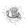
- FIG. 1is a perspective view of a thermostat device according to one embodiment of the present invention, viewed from the distal end side of a leg.
- FIG. 2is a partial cross-sectional view of a thermostat device according to one embodiment of the present invention.
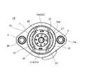
- FIG. 3is a bottom view of the thermostat device according to one embodiment of the present invention.
- 4is an enlarged view showing an enlarged part of the housing of the thermostat device of FIG. 3.
- FIG. FIG. 5is a partial cross-sectional view of a conventional thermostat device.
- a thermostat device 10 according to one embodiment of the present inventionwill be described below with reference to the drawings.
- a thermostat device 10 according to the present embodiment shown in FIGS. 1 to 3is provided, for example, in a coolant system of an engine.
- the thermostat device 10is provided on the inlet side or the outlet side of the engine in the cooling path connecting the radiator and the engine, and opens and closes the cooling path according to the temperature of the coolant, and the temperature of the coolant circulating through the engine to control.
- the thermostat device 10includes a hollow housing 1, a thermoelement 17 having one end inserted into the housing 1, and a valve provided on the outer periphery of the thermoelement 17 for opening and closing a cooling passage. It comprises a body 15 , a coil spring 16 as a biasing member that biases the valve body 15 in the closing direction, and a frame 19 that supports one end of the coil spring 16 .
- the upper and lower sides of the thermostat device 10 shown in FIG. 2are simply referred to as “upper” and "lower.”
- the housing 1is made of synthetic resin.
- the housing 1includes a substantially truncated cylindrical main body 20 having an opening 20c formed at the lower end thereof, a pair of legs 21, 21 extending downward from the lower end opening edge of the main body 20 so as to face each other, and the main body 20. and a pair of flanges 2, 2 projecting outward from the outer circumference of the lower end of the body portion 20.
- the coolantpasses through the connection port 23, the inside of the main body 20, and the opening 20c, which form part of the cooling path.
- a bolt hole 2ais formed in each of the pair of flanges 2,2.
- a metal sleeve(not shown) is press-fitted into the bolt hole 2a, and a bolt (not shown) for fixing the thermostat device 10 to a mating member is inserted through the sleeve.
- An annular groove 20dis formed so as to surround the opening 20c in the lower end opening edge of the body portion 20 located inside the bolt hole 2a, and a gasket 25 is fitted in the groove 20d.
- the gasket 25seals between the thermostat device 10 and the mating member, and prevents the coolant flowing inside the housing 1 from leaking to the outside when the thermostat device 10 is attached to the mating member.
- the inner side (inner side) of the gasket 25 in the body portion 20is the inner side of the housing 1 .
- a ring-shaped valve seat 20bis formed on the inner periphery immediately above the lower end opening edge of the body portion 20 located inside the housing 1, and the valve body 15 is seated and separated from the valve seat 20b, thereby closing the cooling path. is opened and closed.
- thermoelement 17is inserted inside the housing 1 .
- the thermo-element 17is arranged in the axial center portion of the main body portion 20 along the axial center line.
- the thermo-element 17includes an element case 30 in which a thermal expansion material such as wax is enclosed, and a piston 3 inserted into the element case 30 so as to be advanced and retracted.
- the piston 3moves out of the element case 30 and the thermo-element 17 extends.
- the piston 3enters the element case 30 and the thermo-element 17 contracts.
- the thermo-element 17expands and contracts depending on the temperature.
- thermo-element 17The tip of the piston 3 located at the upper end of the thermo-element 17 is fitted to a cylindrical boss 20a formed inside the main body 20 at the top. Therefore, upward movement of the piston 3 with respect to the housing 1 is prevented. Therefore, when the thermo-element 17 expands and contracts, the element case 30 moves up and down without changing the position of the piston 3 with respect to the housing 1 .
- a valve body 15is fixed to the outer circumference of the element case 30 .
- the valve body 15moves up and down together with the element case 30 as the thermo-element 17 expands and contracts.
- the valve body 15moves downward, the valve body 15 is separated from the valve seat 20b and the cooling liquid can pass between them, allowing communication of the cooling path. be done.
- the thermo-element 17contracts and the valve element 15 moves upward and is seated on the valve seat 20b, communication of the cooling passage is cut off. In this manner, the valve body 15 opens and closes the cooling path by seating and removing from the valve seat 20b.
- the upper end of the coil spring 16contacts the back surface of the valve body 15 .
- This coil spring 16is arranged so as to surround the thermo-element 17 .
- a lower end (one end) of the coil spring 16is supported by a frame 19 .
- the frame 19is caught by the tips of a pair of legs 21, 21 formed on the housing 1 and prevented from moving downward with respect to the housing 1.
- a through hole 19 ais formed in the center of the frame 19 .
- the element case 30is vertically movably inserted through the through hole 19a. That is, the element case 30 can move up and down with respect to the frame 19 .
- the coil spring 16is a compression spring and is arranged in a compressed state between the valve body 15 and the frame 19 . Therefore, the valve element 15 is urged upward (toward the valve seat 20b) by the coil spring 16. As shown in FIG. In this configuration, when the cooling liquid around the thermo-element 17 becomes hot and the thermo-element 17 expands, the valve body 15 moves downward against the biasing force of the coil spring 16 and leaves the valve seat 20b. On the other hand, when the cooling liquid around the thermo-element 17 becomes low temperature and the thermo-element 17 contracts, the valve body 15 moves upward according to the biasing force of the coil spring 16 and approaches the valve seat 20b.
- the housing 1has a pair of legs 21 , 21 and reinforcing ribs 22 arranged at the base of each leg 21 .
- Hooks 21aare formed at the ends of the pair of legs 21, 21, respectively, and the engaging portions 19b formed on the frame 19 are hooked on the hooks 21a.
- the center side of the body part 20is the inside, and the opposite side (the outer peripheral side, the side away from the center) is the outside.
- the outer surface 21b of the leg 21curves in an arc along the edge of the opening 20c.
- a circle connecting the outer surfaces of the pair of legs 21, 21is a circle C.
- a rib 22is formed at the base of each leg 21 so as to extend from the base and both sides of the leg 21 .
- each rib 22is connected to an outer surface 21b of the leg 21, and curves from the outer surface 21b of the leg 21 toward the inside of the circle C. As shown in FIG. As a result, it is possible to improve the durability against the force applied in the direction of opening (separating) the tips of the pair of legs 21 , 21 . Therefore, the opening of the leg 21 of the housing 1 can be suppressed.
- the thermostat device 10is arranged on the inlet side of the engine and the coolant flows from the connection port 23 through the radiator, the pressure of the coolant on the connection port side does not cause the valve element 15 to open. , it is necessary to increase the set load of the coil spring 16, and the force acting in the direction of opening the leg 21 increases.
- the present inventionis particularly effective to apply the present invention to the thermostat device 10 arranged on the engine inlet side.
- the present inventionmay be applied to a thermostat device arranged on the engine outlet side.
- the ribs 22are entirely arranged inside the circle C, so that the ribs 22 do not interfere with the mating member when the thermostat device 10 is mounted on the mating member. Therefore, according to the above configuration, even if the ribs 22 for reinforcement are provided, it is possible to suppress deterioration in mountability of the thermostat device 10 .
- the seal line of the gasket 25 for sealing between the housing 1 and the mating memberpasses through the outside of the leg 21, but the seal line can be arranged inside the portion other than the outside of the leg 21.
- the housing 1can be made smaller, and the weight of the thermostat device 10 can be reduced, and the mounting space can be saved.
- the outer surface 21b of the rib 22is curved, but this is not the only option. You may incline so that it may go to the inner side of circle C from 21b. Even in such a case, similarly to the present embodiment, it is possible to suppress the opening of the legs 21 of the housing 1 and to suppress deterioration in mountability of the thermostat device 10 .
- the outer surface 22b of the rib 22is curved, and the curvature radius R2 of the outer surface 22b is smaller than the curvature radius R1 of the outer surface 21b of the leg 21 (R2 ⁇ R1). .
- the length of the rib 22can be secured while the inward protrusion amount of the rib 22 can be suppressed. It is possible to eliminate the need to change the design of the positioned valve body 15 and the like.
- the outer surface 21b of the leg 21 and the outer surface 22b of the rib 22can be connected in a curved line, and the angle ( Edge) can be suppressed, so stress can be suppressed from concentrating on this corner.
- the above configurationis more advantageous in enhancing the durability of the leg 21 .
- its curvature radius R2may be the same as or larger than the curvature radius R1 of the outer surface 21b of the leg 21, and can be changed as appropriate.
- concave recessed portions 22aare formed on the inner side surfaces 22c of the ribs 22.
- the inner side surface 22c of the rib 22continues to the inner side surface 21c of the leg 21 and curves outward from the inner side surface 21c of the leg 21 to form the recess 22a.
- the width of the ribs 22can be made as uniform as possible while suppressing the amount of protrusion of the ribs 22 inward, so that the molding accuracy can be improved when the housing 1 is injection-molded with a synthetic resin.
- the housing 1may be made of metal.
- the height (thickness), width and length of the ribs 22can be appropriately changed according to the load or endurance conditions.
Landscapes
- Engineering & Computer Science (AREA)
- General Engineering & Computer Science (AREA)
- Mechanical Engineering (AREA)
- Physics & Mathematics (AREA)
- General Physics & Mathematics (AREA)
- Automation & Control Theory (AREA)
- Fluid Mechanics (AREA)
- Chemical & Material Sciences (AREA)
- Combustion & Propulsion (AREA)
- Temperature-Responsive Valves (AREA)
- Control Of Temperature (AREA)
Abstract
Description
Translated fromJapanese本発明はサーモスタット装置に関する。The present invention relates to thermostat devices.
サーモスタット装置の中には、例えば特許文献1に開示されるように(図5参照)、中空のハウジング60と、一端がハウジング60内に挿入されて温度に応じて伸縮するサーモエレメント51と、サーモエレメント51の伸縮により開閉する弁体52と、前記弁体52を閉じる方向へ付勢するコイルスプリング53と、コイルスプリング53の一端を支えるフレーム65とを備え、このフレーム65をハウジング60の一対の脚62、62の先端に引っ掛けるものがある。As disclosed in Patent Document 1 (see FIG. 5), the thermostat device includes a
図5に示すような、ハウジング60の脚62の先端にばね受けとして機能するフレーム65を引っ掛けるサーモスタット装置では、脚62にコイルスプリング53のばね荷重が作用する。このような場合であっても、ハウジング60がアルミ等の金属製の場合には、脚62の耐久性に問題はない。In a thermostat device in which a
しかしながら、コストの削減、軽量化等を目的として、一対の脚62、62を含むハウジング60を金属製からそのまま合成樹脂製に変更した場合、耐久性が低下して、ばね荷重によって一対の脚62、62の先端が互いに離れて一対の脚62、62が開くように変形し、フレーム65が脱落する虞がある。However, if the
尚、一対の脚62、62の開きを抑制する方法としては、脚の厚み、幅、又は長さを大きくしたり、一対の脚62、62の外側に補強用のリブを設ける方法が考えられるが、そのようにした場合、大きな脚62又は補強用のリブがサーモスタット装置を搭載する相手側部材と干渉して搭載できなくなる虞がある。
具体的には、例えば、サーモスタット装置が自動車におけるエンジンの入口側に配置される場合、サーモスタット装置は、エンジンに冷却液を供給するウォーターポンプに取り付けられる。この場合、ウォーターポンプ側のサーモスタット装置を取り付けるための部材が相手側部材であり、この相手側部材には、サーモスタット装置の脚部及びその内側のサーモエレメント等を挿し込む取付孔が形成されている。この取付孔の大きさは、自由に変更できないことがあり、前述のように、サーモスタット装置の脚62を大きくしたり、脚62の外側に補強用のリブを設けたりすると、相手側部材の取付孔に挿入できなくなる虞がある。
換言すると、相手側部材の取付孔を変更せずにサーモスタット装置の脚62を大きくしたり、脚62の外側に補強用のリブを設けたりすると、脚62の外側に設けられ、サーモスタット装置のハウジングと相手側部材との間をシールするガスケットのシールラインが成立せずに、ガスケットの取付スペースを確保できなくなる虞がある。As a method of suppressing the opening of the pair of
Specifically, for example, when the thermostat device is arranged on the inlet side of the engine in an automobile, the thermostat device is attached to a water pump that supplies coolant to the engine. In this case, the member for mounting the thermostat device on the water pump side is the mating member, and the mating member is formed with mounting holes into which the legs of the thermostat device and the thermoelement inside thereof are inserted. . In some cases, the size of this mounting hole cannot be freely changed. There is a risk that it will not be possible to insert it into the hole.
In other words, if the
本発明は、前記した点に着目してなされたものであり、ハウジングの脚の開きを抑制できるとともに、搭載性の低下を抑制できるサーモスタット装置を提供することを目的とする。The present invention has been made in view of the above-mentioned points, and an object of the present invention is to provide a thermostat device capable of suppressing the opening of the legs of the housing and suppressing deterioration of mountability.
前記した課題を解決するために、本発明に係るサーモスタット装置は、内側に弁座が形成されるハウジングと、一端が該ハウジングの内側に挿入されて温度に応じて伸縮作動するサーモエレメントと、前記サーモエレメントの外周に設けられて前記サーモエレメントの伸縮作動により、前記弁座に離着座する弁体と、前記弁体を弁座側へ付勢する付勢部材と、前記付勢部材の一端を支持するフレームと、を備え、前記ハウジングは、一端に開口を有して内側に前記弁座が形成される中空の本体部と、前記本体部の開口縁から起立して、先端に前記フレームが引っ掛かる一対の脚と、前記開口縁に設けられて前記脚の根元の両側部に連なるリブと、を有し、前記脚の外側面は、前記脚の先端側から見て円弧状に形成されており、前記リブの外側面は、前記脚の前記外側面から一対の前記脚の前記外側面を繋ぐ円の内側へ向かうよう、湾曲又は傾斜することを特徴とする。In order to solve the above-described problems, a thermostat device according to the present invention comprises a housing having a valve seat formed therein; a thermo-element having one end inserted into the housing and expanding and contracting according to temperature; A valve disc provided on the outer circumference of a thermo-element and seated and separated from the valve seat by expansion and contraction of the thermo-element, an urging member for urging the valve disc toward the valve seat, and one end of the urging member. a frame for supporting the housing, the housing comprising a hollow main body having an opening at one end and having the valve seat formed therein; It has a pair of legs that are hooked and ribs that are provided on the edge of the opening and continue to both sides of the base of the legs, and the outer surfaces of the legs are formed in an arc shape when viewed from the tip side of the legs. The outer surface of the rib is curved or slanted from the outer surface of the leg toward the inner side of a circle connecting the outer surfaces of the pair of legs.
このような構成によれば、一対の脚の根元両側部に連なるリブの外側面が、一対の脚の外側面を繋ぐ円の内側へ向かうよう、湾曲又は傾斜するので、一対の脚の先端を開く(離間させる)方向に加わる力に対し、耐久性を向上できる。また、リブが一対の脚の外側面を繋ぐ円から外側へ出ず、前記円の内側に位置するので、サーモスタット装置を相手方部材に搭載する際に、リブが相手側部材に干渉することがなく、搭載性を向上できる。
さらには、ハウジングと相手方部材との間をシールするガスケットのシールラインは、脚の外側を通るが、その脚の外側以外の部分では、シールラインを内側へ配置できる。このため、ハウジングを小型にでき、サーモスタット装置の軽量化及び取付スペースの省スペース化が可能になる。According to such a configuration, the outer side surfaces of the ribs connected to both sides of the base of the pair of legs are curved or inclined toward the inside of the circle connecting the outer side surfaces of the pair of legs, so that the tips of the pair of legs are curved or inclined. Durability can be improved against the force applied in the opening (separating) direction. In addition, since the rib does not protrude outward from the circle connecting the outer surfaces of the pair of legs and is positioned inside the circle, the rib does not interfere with the counterpart member when the thermostat device is mounted on the counterpart member. , the mountability can be improved.
Furthermore, the seal line of the gasket that seals between the housing and the mating member passes through the outside of the leg, but the seal line can be arranged inside the portion other than the outside of the leg. Therefore, the housing can be made smaller, and the weight of the thermostat device can be reduced, and the installation space can be saved.
また、前記サーモスタット装置において、前記リブの外側面の曲率半径を、前記脚の外側面の曲率半径よりも小さくしてもよい。このようにすると、リブの長さを確保しつつ、リブの内側への突出量を抑制できる。さらに、脚の外側面とリブの外側面との境界に角(エッジ)ができるのを抑制できるので、この角に応力が集中するのを防ぐことができる。よって、上記構成によれば、脚の耐久性を高める上で、より有利である。Further, in the thermostat device, the radius of curvature of the outer surface of the rib may be smaller than the radius of curvature of the outer surface of the leg. By doing so, it is possible to suppress the inward protrusion of the rib while ensuring the length of the rib. Furthermore, since it is possible to suppress the formation of an edge at the boundary between the outer surface of the leg and the outer surface of the rib, it is possible to prevent stress from concentrating on this edge. Therefore, the above configuration is more advantageous in increasing the durability of the legs.
また、前記サーモスタット装置において、前記リブの内側面に、凹形状の窪み部が形成されていてもよい。このようにすると、リブの内側への突出量を抑制しつつ、リブの幅をなるべく均一にできるので、ハウジングが合成樹脂で射出成型される場合に、成形精度を高めることができる。Further, in the thermostat device, a recessed portion having a concave shape may be formed on the inner surface of the rib. In this way, the width of the ribs can be made as uniform as possible while suppressing the amount of protrusion of the ribs inward, so that molding accuracy can be improved when the housing is injection-molded from a synthetic resin.
本発明に係るサーモスタット装置によれば、ハウジングの脚の開きを抑制できるとともに、搭載性の低下を抑制できる。According to the thermostat device of the present invention, it is possible to suppress the opening of the legs of the housing and to suppress the deterioration of mountability.
以下、本発明の一実施の形態に係るサーモスタット装置を図面に基づき説明する。図1から図3に示す本実施の形態に係るサーモスタット装置10は、例えばエンジンの冷却液系に設けられる。具体的には、サーモスタット装置10は、ラジエータとエンジンとを繋ぐ冷却路におけるエンジンの入口側又は出口側に設けられ、冷却液の温度に応じて冷却路を開閉し、エンジンを循環する冷却液温度を制御する。A thermostat device according to one embodiment of the present invention will be described below with reference to the drawings. A
前記サーモスタット装置10は、図2に示すように、中空のハウジング1と、このハウジング1内に一端が挿入されるサーモエレメント17と、このサーモエレメント17の外周に設けられ、冷却路を開閉する弁体15と、この弁体15を閉じ方向へ付勢する付勢部材としてのコイルスプリング16と、コイルスプリング16の一端を支持するフレーム19とを備える。以下、説明の便宜上、図2に示すサーモスタット装置10の上下を単に「上」「下」という。As shown in FIG. 2, the
本実施の形態において、ハウジング1は、合成樹脂により形成されている。ハウジング1は、下端に開口20cが形成される略有頂筒状の本体部20と、この本体部20の下端開口縁から下方へ相対向して延びる一対の脚21,21と、本体部20の頂部に設けられるラジエータ側の接続口23と、本体部20の下端外周から外側へ張り出す一対のフランジ2,2とを有する。冷却液は、接続口23、本体部20の内側、及び開口20cを通過するようになっており、これらは冷却路の一部を構成する。
一対のフランジ2,2には、それぞれボルト孔2aが形成される。ボルト孔2aには、金属製のスリーブ(符示せず)が圧入され、このスリーブにサーモスタット装置10を相手側部材へ固定するためのボルト(図示せず)が挿通される。このボルト孔2aよりも内側に位置する本体部20の下端開口縁には、開口20cを取り囲むように環状の溝20dが形成され、この溝20dにガスケット25が装着される。
このガスケット25は、サーモスタット装置10と相手側部材との間をシールし、サーモスタット装置10を相手側部材に取り付けた状態で、ハウジング1内を流れる冷却液が外に漏れるのを防止する。本体部20におけるガスケット25よりも内側(内部側)が、ハウジング1の内側である。
このハウジング1の内側に位置する本体部20の下端開口縁の直上部内周に、環状の弁座20bが形成されており、この弁座20bに弁体15が離着座することで、冷却路が開閉される。In this embodiment, the
A
The gasket 25 seals between the
A ring-
ハウジング1の内側に、サーモエレメント17が挿入される。サーモエレメント17は、本体部20の軸芯部に、その軸芯線に沿うように配置される。サーモエレメント17は、内部にワックス等の熱膨張体が封入されるエレメントケース30と、このエレメントケース30に進退可能に挿入されるピストン3とを備える。
そして、エレメントケース30周囲の冷却液の温度が上昇し、内部の熱膨張体が膨張すると、ピストン3がエレメントケース30から退出し、サーモエレメント17が伸長する。反対に、エレメントケース30周囲の冷却液の温度が低下し、内部の熱膨張体が収縮すると、ピストン3がエレメントケース30に進入し、サーモエレメント17が収縮する。このように、サーモエレメント17は、温度に応じて伸縮作動する。
サーモエレメント17の上端に位置するピストン3の先端は、本体部20の内側、頂部に形成された筒状のボス部20aに篏合する。このため、ハウジング1に対するピストン3の上方への移動が阻止される。よって、サーモエレメント17が伸縮作動すると、ハウジング1に対するピストン3の位置は変わらず、エレメントケース30が上下に移動する。A
When the temperature of the cooling liquid around the
The tip of the
エレメントケース30の外周に、弁体15が固定されている。これにより、弁体15は、サーモエレメント17の伸縮に伴ってエレメントケース30とともに上下に移動する。そして、サーモエレメント17が伸長して弁体15が下方へ移動すると、弁体15が弁座20bから離座してこれらの間を冷却液が通過できるようになるので、冷却路の連通が許容される。反対に、サーモエレメント17が収縮し、弁体15が上方へ移動して弁座20bに着座すると、冷却路の連通が遮断される。このように、弁体15は、弁座20bに離着座して冷却路を開閉する。A
弁体15の背面には、コイルスプリング16の上端が当接する。このコイルスプリング16は、サーモエレメント17の周りを囲うように配置されている。また、コイルスプリング16の下端(一端)は、フレーム19で支えられている。The upper end of the
フレーム19は、ハウジング1に形成される一対の脚21,21の先端部に引っ掛かり、ハウジング1に対する下方への移動が阻止される。また、フレーム19の中心部には、貫通孔19aが形成されている。この貫通孔19aに、エレメントケース30が上下動自在に挿通される。つまり、エレメントケース30は、フレーム19に対して上下動可能となっている。The
コイルスプリング16は、圧縮ばねであり、弁体15とフレーム19との間に圧縮された状態で配置される。このため、弁体15は、コイルスプリング16で上方(弁座20b側)へ付勢される。この構成において、サーモエレメント17の周囲の冷却液が高温になり、サーモエレメント17が伸長すると、弁体15がコイルスプリング16の付勢力に抗して下方へ移動して、弁座20bから離れる。その一方、サーモエレメント17の周囲の冷却液が低温になり、サーモエレメント17が収縮すると、弁体15がコイルスプリング16の付勢力に従って上方へ移動して、弁座20bに近づく。The
図1に示すように、ハウジング1は、一対の脚21,21と、各脚21の根元に配置される補強用のリブ22とを有する。また、一対の脚21,21の先端には、それぞれ引掛け部21aが形成されており、この引掛け部21aにフレーム19に形成された係合部19bが引っ掛かる。As shown in FIG. 1, the
ハウジング1を構成する各部において、本体部20の中心側が内側、反対側(外周側、中心から離れる側)が外側である。図4に示すように、各脚21を下方(先端側)から見た状態で、脚21の外側面21bは開口20cの縁に沿うように円弧状に湾曲する。一対の脚21,21の外側面を繋ぐ円を、円Cとする。各脚21の根元には、その脚21の根元、両側部から延長するように、リブ22が形成されている。In each part constituting the
各リブ22の外側面22bは、脚21の外側面21bに連なり、この脚21の外側面21bから円Cの内側へ向けて湾曲する。これにより、一対の脚21,21の先端を開く(離間させる)方向に加わる力に対し、耐久性を向上できる。よって、ハウジング1の脚21の開きを抑制できる。
特に、サーモスタット装置10が、エンジンの入口側に配置され、接続口23からラジエータを経由した冷却液が流入する場合には、この接続口側の冷却液の圧力で弁体15が開弁しないよう、コイルスプリング16のセット荷重を大きくする必要があり、脚21を開く方向へ作用する力が大きくなる。よって、このようなエンジン入口側に配置されるサーモスタット装置10に、本発明が適用されるのが特に有効である。しかし、本発明は、エンジン出口側に配置されるサーモスタット装置に適用されても良い。
また、上記構成によれば、リブ22全体が円Cよりも内側に配置されるため、サーモスタット装置10を相手方部材に搭載する際に、リブ22が相手側部材に干渉することがない。よって、上記構成によれば、補強用のリブ22を設けたとしても、サーモスタット装置10の搭載性が低下するのを抑制できる。
さらには、ハウジング1と相手方部材との間をシールするガスケット25のシールラインは、脚21の外側を通るが、その脚21の外側以外の部分では、シールラインを内側へ配置できる。このため、ハウジング1を小型にでき、サーモスタット装置10の軽量化及び取付スペースの省スペース化が可能になる。
なお、本実施の形態では、リブ22の外側面21bが湾曲しているが、この限りではなく、図4中一点鎖線で記載するように、リブ22の外側面22bが、脚21の外側面21bから円Cの内側へ向かうよう傾斜していても良い。このような場合であっても、本実施の形態と同様に、ハウジング1の脚21の開きを抑制できるとともに、サーモスタット装置10の搭載性が低下するのを抑制できる。An
In particular, when the
Further, according to the above configuration, the
Furthermore, the seal line of the
In this embodiment, the
また、本実施の形態のサーモスタット装置10では、リブ22の外側面22bが湾曲し、その外側面22bの曲率半径R2が、脚21の外側面21bの曲率半径R1よりも小さい(R2<R1)。当該構成によれば、リブ22の長さを確保しつつ、リブ22の内側への突出量を抑制できるので、リブ22を円Cの内側へ向かうように形成しても、リブ22の内側に位置する弁体15等の設計変更を不要にできる。
さらに、上記構成によれば、脚21の外側面21bとリブ22の外側面22bとを曲線的に繋げることができ、脚21の外側面21bとリブ22の外側面22bとの間に角(エッジ)ができるのを抑制できるので、この角に応力が集中するのを抑制できる。よって、上記構成によれば、脚21の耐久性を高める上で、より有利である。
しかし、リブ22の外側面22bが湾曲する場合、その曲率半径R2は、脚21の外側面21bの曲率半径R1と同じであっても、それより大きくても良く、適宜変更できる。Further, in the
Furthermore, according to the above configuration, the
However, when the
また、リブ22の内側面22cには、凹形状の窪み部22aが形成されている。より詳しくは、リブ22の内側面22cは、脚21の内側面21cに連なり、この脚21の内側面21cから外側へ湾曲して窪み部22aを形成する。当該構成によれば、リブ22の内側への突出量を抑制しつつ、リブ22の幅をなるべく均一にできるので、ハウジング1が合成樹脂で射出成型される場合に、成形精度を高めることができる。
しかし、リブ22の内側面22cに、窪み部22aを形成しなくてもよく、ハウジング1の素材及び成型方法も適宜変更できる。具体的には、ハウジング1は、金属製であっても良い。また、リブ22の高さ(厚さ)、幅、長さは、荷重負荷又は耐久条件に応じて、適宜変更できる。In addition, concave recessed
However, it is not necessary to form the recessed
以上、本発明の好ましい実施の形態を詳細に説明したが、特許請求の範囲から逸脱しない限り、改造、変形、及び変更が可能である。Although the preferred embodiments of the present invention have been described in detail above, modifications, variations, and changes are possible without departing from the scope of the claims.
1 ハウジング
2 フランジ
3 ピストン
10 サーモスタット装置
15 弁体
16 コイルスプリング(付勢部材)
19 フレーム
19b 係合部
20 本体部
20a ボス部
20b 弁座
20c 開口
21 脚
21a 引掛け部
21b 脚の外側面
22 リブ
22a 窪み部
22b リブの外側面
C 一対の脚の外側面を繋ぐ円
R1 脚の外側面の曲率半径
R2 リブの外周面の曲率半径
19
Claims (3)
Translated fromJapanese一端が該ハウジングの内側に挿入されて温度に応じて伸縮作動するサーモエレメントと、
前記サーモエレメントの外周に設けられて前記サーモエレメントの伸縮作動により、前記弁座に離着座する弁体と、
前記弁体を弁座側へ付勢する付勢部材と、
前記付勢部材の一端を支持するフレームと、を備え、
前記ハウジングは、
一端に開口を有して内側に前記弁座が形成される中空の本体部と、
前記本体部の開口縁から起立して、先端に前記フレームが引っ掛かる一対の脚と、
前記開口縁に設けられて前記脚の根元の両側部に連なるリブと、を有し、
前記脚の外側面は、前記脚の先端側から見て円弧状に形成されており、
前記リブの外側面は、前記脚の前記外側面から一対の前記脚の前記外側面を繋ぐ円の内側へ向かうよう、湾曲又は傾斜することを特徴とするサーモスタット装置。a housing having a valve seat formed therein;
a thermo element whose one end is inserted inside the housing and expands and contracts according to temperature;
a valve body that is provided on the outer periphery of the thermo-element and moves to and from the valve seat by expansion and contraction of the thermo-element;
a biasing member that biases the valve body toward the valve seat;
a frame that supports one end of the biasing member;
The housing is
a hollow body having an opening at one end and having the valve seat formed therein;
a pair of legs standing from the edge of the opening of the main body and having the frame hooked at the tip thereof;
a rib provided at the edge of the opening and continuing to both sides of the base of the leg,
The outer surface of the leg is formed in an arc shape when viewed from the tip side of the leg,
The thermostat device according to claim 1, wherein the outer surface of the rib is curved or inclined from the outer surface of the leg toward the inner side of a circle connecting the outer surfaces of the pair of legs.
Priority Applications (4)
| Application Number | Priority Date | Filing Date | Title |
|---|---|---|---|
| US18/270,082US12247675B2 (en) | 2021-01-28 | 2021-11-11 | Thermostat device |
| EP21923073.7AEP4286667A4 (en) | 2021-01-28 | 2021-11-11 | THERMOSTAT |
| CA3205680ACA3205680A1 (en) | 2021-01-28 | 2021-11-11 | Thermostat device |
| AU2021423963AAU2021423963A1 (en) | 2021-01-28 | 2021-11-11 | Thermostat device |
Applications Claiming Priority (2)
| Application Number | Priority Date | Filing Date | Title |
|---|---|---|---|
| JP2021012284AJP7536669B2 (en) | 2021-01-28 | 2021-01-28 | Thermostat device |
| JP2021-012284 | 2021-01-28 |
Publications (1)
| Publication Number | Publication Date |
|---|---|
| WO2022163068A1true WO2022163068A1 (en) | 2022-08-04 |
Family
ID=82653153
Family Applications (1)
| Application Number | Title | Priority Date | Filing Date |
|---|---|---|---|
| PCT/JP2021/041518CeasedWO2022163068A1 (en) | 2021-01-28 | 2021-11-11 | Thermostat device |
Country Status (6)
| Country | Link |
|---|---|
| US (1) | US12247675B2 (en) |
| EP (1) | EP4286667A4 (en) |
| JP (1) | JP7536669B2 (en) |
| AU (1) | AU2021423963A1 (en) |
| CA (1) | CA3205680A1 (en) |
| WO (1) | WO2022163068A1 (en) |
Families Citing this family (1)
| Publication number | Priority date | Publication date | Assignee | Title |
|---|---|---|---|---|
| JP7593819B2 (en)* | 2021-01-28 | 2024-12-03 | 日本サーモスタット株式会社 | Thermostat device and manufacturing method thereof |
Citations (3)
| Publication number | Priority date | Publication date | Assignee | Title |
|---|---|---|---|---|
| JP2006329272A (en)* | 2005-05-24 | 2006-12-07 | Kuzee:Kk | Valve device |
| JP2016008568A (en)* | 2014-06-25 | 2016-01-18 | 日本サーモスタット株式会社 | Thermostat valve |
| JP2018025269A (en)* | 2016-08-12 | 2018-02-15 | 富士精工株式会社 | Plug integrated thermo valve |
Family Cites Families (18)
| Publication number | Priority date | Publication date | Assignee | Title |
|---|---|---|---|---|
| US4978060A (en)* | 1990-03-15 | 1990-12-18 | Eaton Corporation | Engine coolant thermostat with pressure relief feature |
| US5381953A (en)* | 1993-02-23 | 1995-01-17 | Fishman; Joseph | Fail-open locking element and thermostat incorporating same |
| JP4187131B2 (en)* | 2000-04-28 | 2008-11-26 | 日本サーモスタット株式会社 | Thermostat device |
| JP4498636B2 (en)* | 2001-04-27 | 2010-07-07 | 日本サーモスタット株式会社 | Thermostat device |
| JP2003328753A (en)* | 2002-05-10 | 2003-11-19 | Nippon Thermostat Co Ltd | Electronically controlled thermostat |
| JP4212041B2 (en) | 2003-11-27 | 2009-01-21 | 日本サーモスタット株式会社 | Thermostat device |
| JP4225551B2 (en)* | 2004-05-21 | 2009-02-18 | 日本サーモスタット株式会社 | Thermostat device |
| KR100755264B1 (en)* | 2006-03-17 | 2007-09-04 | 고려전자주식회사 | Thermostat device |
| CA2727578C (en)* | 2008-07-10 | 2016-02-09 | Nippon Thermostat Co., Ltd. | Thermostat device |
| JP5039803B2 (en)* | 2010-03-04 | 2012-10-03 | 日本サーモスタット株式会社 | Cooling device for internal combustion engine |
| JP4649535B1 (en)* | 2010-03-29 | 2011-03-09 | 富士精工株式会社 | Thermostat device |
| JP5164281B2 (en)* | 2010-04-27 | 2013-03-21 | 日本サーモスタット株式会社 | Fluid control valve device |
| JP5789094B2 (en)* | 2010-11-08 | 2015-10-07 | 日本サーモスタット株式会社 | Cooling device for internal combustion engine |
| JP6744137B2 (en)* | 2016-06-07 | 2020-08-19 | 日本サーモスタット株式会社 | Thermostat device |
| JP7211873B2 (en)* | 2019-04-04 | 2023-01-24 | 日本サーモスタット株式会社 | thermostat device |
| JP7464504B2 (en)* | 2020-11-16 | 2024-04-09 | 日本サーモスタット株式会社 | Thermo valve and thermo valve connector |
| JP7332643B2 (en)* | 2021-02-17 | 2023-08-23 | 日本サーモスタット株式会社 | thermostat device |
| JP7393371B2 (en)* | 2021-02-17 | 2023-12-06 | 日本サーモスタット株式会社 | thermostat device |
- 2021
- 2021-01-28JPJP2021012284Apatent/JP7536669B2/enactiveActive
- 2021-11-11CACA3205680Apatent/CA3205680A1/enactivePending
- 2021-11-11AUAU2021423963Apatent/AU2021423963A1/enactivePending
- 2021-11-11WOPCT/JP2021/041518patent/WO2022163068A1/ennot_activeCeased
- 2021-11-11EPEP21923073.7Apatent/EP4286667A4/enactivePending
- 2021-11-11USUS18/270,082patent/US12247675B2/enactiveActive
Patent Citations (3)
| Publication number | Priority date | Publication date | Assignee | Title |
|---|---|---|---|---|
| JP2006329272A (en)* | 2005-05-24 | 2006-12-07 | Kuzee:Kk | Valve device |
| JP2016008568A (en)* | 2014-06-25 | 2016-01-18 | 日本サーモスタット株式会社 | Thermostat valve |
| JP2018025269A (en)* | 2016-08-12 | 2018-02-15 | 富士精工株式会社 | Plug integrated thermo valve |
Non-Patent Citations (1)
| Title |
|---|
| See also references ofEP4286667A4* |
Also Published As
| Publication number | Publication date |
|---|---|
| EP4286667A4 (en) | 2025-01-01 |
| JP7536669B2 (en) | 2024-08-20 |
| US12247675B2 (en) | 2025-03-11 |
| US20240068588A1 (en) | 2024-02-29 |
| CA3205680A1 (en) | 2022-08-04 |
| JP2022115621A (en) | 2022-08-09 |
| AU2021423963A1 (en) | 2023-07-27 |
| AU2021423963A9 (en) | 2024-10-17 |
| EP4286667A1 (en) | 2023-12-06 |
Similar Documents
| Publication | Publication Date | Title |
|---|---|---|
| CN103026113B (en) | Thermostat device | |
| WO2022163068A1 (en) | Thermostat device | |
| EP2659102A1 (en) | Thermostat for coolant system | |
| KR101875625B1 (en) | Thermostat | |
| US12110817B2 (en) | Thermostat device | |
| US20170254254A1 (en) | Thermostatic valve having a sleeve | |
| JP7593819B2 (en) | Thermostat device and manufacturing method thereof | |
| KR102359939B1 (en) | Coolant control valve unit having holder | |
| JP7671313B2 (en) | Thermo valve for cooling water control | |
| JP7648451B2 (en) | Cover member and thermostat device with cover member | |
| JP7078270B2 (en) | Thermo actuator | |
| JP3545997B2 (en) | Wax-type thermoresponsive control valve for engine refrigerant circuit | |
| KR100963436B1 (en) | Automotive Thermostat | |
| CN112594053B (en) | Temperature regulator | |
| US20240219939A1 (en) | Temperature adjustment device | |
| US8205802B2 (en) | Premounted unit of a tube portion and a thermostat valve | |
| WO2025047073A1 (en) | Thermostat device | |
| WO2024090183A1 (en) | Temperature adjustment device | |
| WO2025041463A1 (en) | Thermostat device |
Legal Events
| Date | Code | Title | Description |
|---|---|---|---|
| 121 | Ep: the epo has been informed by wipo that ep was designated in this application | Ref document number:21923073 Country of ref document:EP Kind code of ref document:A1 | |
| WWE | Wipo information: entry into national phase | Ref document number:18270082 Country of ref document:US | |
| ENP | Entry into the national phase | Ref document number:3205680 Country of ref document:CA | |
| ENP | Entry into the national phase | Ref document number:2021423963 Country of ref document:AU Date of ref document:20211111 Kind code of ref document:A | |
| WWE | Wipo information: entry into national phase | Ref document number:2021923073 Country of ref document:EP | |
| NENP | Non-entry into the national phase | Ref country code:DE | |
| ENP | Entry into the national phase | Ref document number:2021923073 Country of ref document:EP Effective date:20230828 | |
| WWG | Wipo information: grant in national office | Ref document number:18270082 Country of ref document:US |