WO2022151920A1 - Augmented reality display device - Google Patents
Augmented reality display deviceDownload PDFInfo
- Publication number
- WO2022151920A1 WO2022151920A1PCT/CN2021/139258CN2021139258WWO2022151920A1WO 2022151920 A1WO2022151920 A1WO 2022151920A1CN 2021139258 WCN2021139258 WCN 2021139258WWO 2022151920 A1WO2022151920 A1WO 2022151920A1
- Authority
- WO
- WIPO (PCT)
- Prior art keywords
- optical waveguide
- coupling
- optical
- grating
- light
- Prior art date
- Legal status (The legal status is an assumption and is not a legal conclusion. Google has not performed a legal analysis and makes no representation as to the accuracy of the status listed.)
- Ceased
Links
Images


Classifications
- G—PHYSICS
- G02—OPTICS
- G02B—OPTICAL ELEMENTS, SYSTEMS OR APPARATUS
- G02B27/00—Optical systems or apparatus not provided for by any of the groups G02B1/00 - G02B26/00, G02B30/00
- G02B27/0081—Optical systems or apparatus not provided for by any of the groups G02B1/00 - G02B26/00, G02B30/00 with means for altering, e.g. enlarging, the entrance or exit pupil
- G—PHYSICS
- G02—OPTICS
- G02B—OPTICAL ELEMENTS, SYSTEMS OR APPARATUS
- G02B27/00—Optical systems or apparatus not provided for by any of the groups G02B1/00 - G02B26/00, G02B30/00
- G02B27/01—Head-up displays
- G02B27/0101—Head-up displays characterised by optical features
- G—PHYSICS
- G02—OPTICS
- G02B—OPTICAL ELEMENTS, SYSTEMS OR APPARATUS
- G02B27/00—Optical systems or apparatus not provided for by any of the groups G02B1/00 - G02B26/00, G02B30/00
- G02B27/01—Head-up displays
- G02B27/017—Head mounted
- G02B27/0172—Head mounted characterised by optical features
- G—PHYSICS
- G02—OPTICS
- G02B—OPTICAL ELEMENTS, SYSTEMS OR APPARATUS
- G02B27/00—Optical systems or apparatus not provided for by any of the groups G02B1/00 - G02B26/00, G02B30/00
- G02B27/42—Diffraction optics, i.e. systems including a diffractive element being designed for providing a diffractive effect
- G02B27/4272—Diffraction optics, i.e. systems including a diffractive element being designed for providing a diffractive effect having plural diffractive elements positioned sequentially along the optical path
- G—PHYSICS
- G02—OPTICS
- G02B—OPTICAL ELEMENTS, SYSTEMS OR APPARATUS
- G02B6/00—Light guides; Structural details of arrangements comprising light guides and other optical elements, e.g. couplings
- G02B6/10—Light guides; Structural details of arrangements comprising light guides and other optical elements, e.g. couplings of the optical waveguide type
- G—PHYSICS
- G02—OPTICS
- G02B—OPTICAL ELEMENTS, SYSTEMS OR APPARATUS
- G02B6/00—Light guides; Structural details of arrangements comprising light guides and other optical elements, e.g. couplings
- G02B6/24—Coupling light guides
- G02B6/26—Optical coupling means
- G02B6/34—Optical coupling means utilising prism or grating
- G—PHYSICS
- G06—COMPUTING OR CALCULATING; COUNTING
- G06T—IMAGE DATA PROCESSING OR GENERATION, IN GENERAL
- G06T19/00—Manipulating 3D models or images for computer graphics
- G06T19/006—Mixed reality
- G—PHYSICS
- G02—OPTICS
- G02B—OPTICAL ELEMENTS, SYSTEMS OR APPARATUS
- G02B6/00—Light guides; Structural details of arrangements comprising light guides and other optical elements, e.g. couplings
- G02B6/10—Light guides; Structural details of arrangements comprising light guides and other optical elements, e.g. couplings of the optical waveguide type
- G02B6/12—Light guides; Structural details of arrangements comprising light guides and other optical elements, e.g. couplings of the optical waveguide type of the integrated circuit kind
- G02B2006/12083—Constructional arrangements
- G02B2006/12107—Grating
- G—PHYSICS
- G02—OPTICS
- G02B—OPTICAL ELEMENTS, SYSTEMS OR APPARATUS
- G02B6/00—Light guides; Structural details of arrangements comprising light guides and other optical elements, e.g. couplings
- G02B6/10—Light guides; Structural details of arrangements comprising light guides and other optical elements, e.g. couplings of the optical waveguide type
- G02B6/12—Light guides; Structural details of arrangements comprising light guides and other optical elements, e.g. couplings of the optical waveguide type of the integrated circuit kind
- G02B2006/12133—Functions
- G02B2006/12147—Coupler
- G—PHYSICS
- G02—OPTICS
- G02B—OPTICAL ELEMENTS, SYSTEMS OR APPARATUS
- G02B27/00—Optical systems or apparatus not provided for by any of the groups G02B1/00 - G02B26/00, G02B30/00
- G02B27/01—Head-up displays
- G02B27/0101—Head-up displays characterised by optical features
- G02B2027/0112—Head-up displays characterised by optical features comprising device for genereting colour display
- G—PHYSICS
- G02—OPTICS
- G02B—OPTICAL ELEMENTS, SYSTEMS OR APPARATUS
- G02B27/00—Optical systems or apparatus not provided for by any of the groups G02B1/00 - G02B26/00, G02B30/00
- G02B27/01—Head-up displays
- G02B27/017—Head mounted
- G02B2027/0178—Eyeglass type
Definitions
- the present applicationrelates to the technical field of augmented reality, and in particular, to an augmented reality display device.
- Augmented reality technologyintegrates virtual information with the real world.
- Augmented reality technology represented by augmented reality glassesis currently emerging in various industries, especially in the security and industrial fields.
- Augmented reality technologyreflects It has an unparalleled advantage and greatly improves the way of information interaction.
- the more mature augmented reality technologiesare mainly divided into prism solution, birdbath solution, free-form surface solution, off-axis holographic lens solution and waveguide (Lightguide) solution. Applications in Reality Glasses.
- the holographic lens schemeuses the unique optical characteristics of holograms, which has the advantages of large field of view (FOV) and small volume, but is limited by the relatively small eye movement range, and the holographic waveguide scheme has advantages in color uniformity (no rainbow effect) and realization of Monolithic full-color waveguides have advantages, but are currently limited in mass production and large fields of view. Waveguides are currently the best solution for augmented reality glasses.
- the waveguide schemeis further divided into geometric waveguide scheme, relief grating waveguide scheme and volume holographic waveguide scheme.
- the geometric waveguide schemegenerally includes a sawtooth structure waveguide and a polarizing film array mirror waveguide (abbreviated as polarized array waveguide).
- the mainstream polarized arrayed waveguideuses a partially transmissive and partially reflective film mirror of the array to display virtual information.
- the polarized arrayed waveguide solutionhas the advantages of lightness, thinness, large eye movement range and uniform color.
- the relief grating waveguide solutioncan be mass-produced by nanoimprinting process. It has the advantages of large field of view and large eye movement range, but it also brings challenges of field of view uniformity and color uniformity. At the same time, the related micro-nano processing The craftsmanship is also a huge challenge.
- the optomechanicalin order to make the central field of view of the optomechanical coincide with the central field of view of the human eye, the optomechanical needs to be vertically coupled with the optical waveguide lens, which makes the degree of freedom in structural design low. Limited by the optical waveguide lens and the optomechanical itself, the field of view coupled out of the image light is small.
- the present applicationprovides an augmented reality display device, and solves the problem of dispersion existing in the optical waveguide sheet by selecting a visible laser light source.
- the optical-mechanical and optical waveguide lensescan still ensure that the optical-mechanical central field of view and the human eye's central field of view overlap in the case of non-vertical coupling, which greatly improves the structural design of the optical-mechanical and optical waveguide lenses degrees of freedom.
- an augmented reality display devicecomprising: an optical machine for emitting image light; at least one layer of optical waveguide lens for coupling in, turning in and out of the image light emitted by the optical machine, at least A layer of optical waveguide lens includes an in-coupling grating area, an optical waveguide substrate, and a turning and out-coupling grating area, wherein the in-coupling grating area is arranged on the first optical surface of the optical waveguide substrate and receives the transmitted image light emitted by the optical machine;
- the optical waveguide substrateis used to transmit the image light through total reflection;
- the turning and coupling-out grating areais arranged on the first optical surface of the optical waveguide substrate, and receives the total reflection light transmitted by the optical waveguide substrate and couples it out;
- the input grating vectorsums the turning The sum of the vector with the out-coupling grating is not zero, wherein the coupling-in angle of the optical machine and each layer of the optical waveguide lens is the same.
- each layer of the optical waveguide sheetcorresponds to one color of image light.
- the gratings in the turning and out-coupling grating regionsneed to satisfy the following formula:
- the wavelength of the transmitted image lightis ⁇
- the angle ⁇ between the surface of the at least one layer of optical waveguide lens and the vertical directionthe coupled-in grating period ⁇ 1
- the turning and outcoupling grating period ⁇ 2is the wavelength of the transmitted image light.
- the included angle ⁇ between the optical machine and the surface normal of the at least one layer of the optical waveguide sheetranges from 0° to 15°.
- the included angle ⁇ between the surface of the at least one layer of the optical waveguide sheet and the vertical direction and the included angle ⁇ between the surface normal of the at least one layer of the optical waveguide sheetsatisfy the following formula:
- the turning and outcoupling grating regioncomprises a one-dimensional surface relief grating or a two-dimensional surface relief grating.
- the light source of the optomechanicaltransmits the image light rays including visible laser light, and the dispersion of the optical waveguide lens is limited by the narrow line width of the light source.
- the line width of the visible light laser, the period of the coupled-in grating, the turning and coupled-out grating periodssatisfy the following formulas:
- ⁇is the angular resolution of the human eye, the angle ⁇ between the optical-mechanical coupling-in direction and the surface normal of the at least one layer of optical waveguide lens, the coupling-in grating period ⁇ 1 , the turning and out-coupling grating period ⁇ 2 , the line width of the visible light laser ⁇ .
- the periods of the turning and coupling-out gratings in both directionsare ⁇ 3
- the included angleis ⁇
- the line width of the visible lasersatisfies the following formula :
- ⁇is the angular resolution of the human eye
- the angle ⁇ between the optical-mechanical coupling direction and the surface normal of the at least one layer of the optical waveguide lens, and the wavelength of the transmitted image lightis ⁇ .
- the optical machineemits RGB three-color light
- at least one layer of optical waveguide lensincludes three layers of optical waveguide lens, each layer of optical waveguide lens has a coupling-in period and a turning and coupling-out period corresponding to each color light
- the sum of the input grating vector and the turning point and the coupling-out grating vectoris not zero, and the coupling angles of the optomechanical and the three-layer optical waveguide mirror are all the same.
- the optomechanicalemits RGB tricolor light, including:
- the linewidth range of blue lightis between 0-2.nm, and the optional range is between 0-0.5nm;
- the line width of green lightis between 0-2.3nm, and the optional range is between 0-0.5nm;
- the linewidth of red lightis in the range of 0-2.7nm, and the optional range is between 0-0.5nm.
- the optical waveguide substratehas a thickness of 0.3 mm to 2.5 mm and a refractive index of 1.4 to 2.2.
- the optical waveguide substrateis transparent and of fixed thickness, has two opposing optical planes, and the material includes glass or quartz.
- a planar optical waveguide lens with a non-zero grating vector sumis proposed, so that the optical-mechanical and optical waveguide lenses can still ensure that the optical-mechanical center field of view and the human eye center field of view are coincident under the condition of non-vertical coupling.
- the freedom of structure design of the optical machine and the optical waveguide sheetis greatly improved.
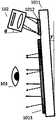
- FIG. 1shows a side view of an augmented reality display device according to an exemplary embodiment.
- FIG. 2shows a side view of an optical machine coupled with an optical waveguide sheet in a vertical manner according to an exemplary embodiment.
- FIG. 3shows a schematic diagram of a coupled-in grating vector and the sum of the inflection and coupled-out grating vectors being zero, according to an exemplary embodiment.
- FIG. 4illustrates a side view of an optical machine coupled with an optical waveguide mirror in a non-perpendicular manner, according to an exemplary embodiment.
- FIG. 5is a schematic diagram illustrating that the sum of the coupled-in grating vector and the inflection and coupled-out grating vectors is not zero, according to an exemplary embodiment.
- FIG. 6illustrates a side view of an optical machine coupled with an optical waveguide sheet in a non-perpendicular manner according to another exemplary embodiment.
- FIG. 7shows a distribution diagram of a light source of an optomechanical in K-space according to an exemplary embodiment.
- FIG. 8shows a distribution diagram of a light source of an optomechanical in K-space after being coupled in according to an exemplary embodiment.
- FIG. 9shows a distribution diagram of the light source of the optomechanical in K space after being coupled out according to an exemplary embodiment.
- FIG. 10shows a schematic perspective view of the turning and outcoupling grating being a two-dimensional grating according to an exemplary embodiment.
- FIG. 11shows a distribution diagram of a light source of an optomechanical in K-space according to another exemplary embodiment.
- FIG. 12shows a distribution diagram of a light source of an optomechanical in K-space after being coupled in according to an exemplary embodiment.
- FIG. 13shows a distribution diagram of the light source of the optomechanical in K space after the two-dimensional grating is coupled out according to an exemplary embodiment.
- FIG. 14illustrates a side view of an opto-mechanical coupled with an RGB three-layer optical waveguide sheet in a non-perpendicular manner, according to an example embodiment.
- FIG. 15illustrates a side view of an opto-mechanical coupled to an RGB three-layer optical waveguide sheet in a non-perpendicular manner according to another example embodiment.
- Example embodimentswill now be described more fully with reference to the accompanying drawings.
- Example embodimentscan be embodied in various forms and should not be construed as limited to the embodiments set forth herein; rather, these embodiments are provided so that this application will be thorough and complete, and will fully convey the concept of example embodiments to those skilled in the art.
- the same reference numerals in the drawingsdenote the same or similar parts, and thus their repeated descriptions will be omitted.
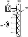
- FIG. 1shows a side view of an augmented reality display device according to an exemplary embodiment.
- a currently known augmented reality display device 100is shown in FIG. 1 . It includes an optical waveguide lens 101 and an optical machine 102 .
- the optical waveguide lens 101includes an optical waveguide substrate 1011 , a coupling-in grating region 1012 , and a turning and coupling-out grating region 1013 .
- the coupled-in grating regionis a one-dimensional surface relief grating.
- the turning and coupling-out grating regionscan be either one-dimensional surface relief gratings or two-dimensional surface relief gratings.
- the diffracted lightis totally reflected by the optical waveguide substrate 1011 and transmitted to the turning and coupling-out grating region 1013, and finally diffracted to the human eye 103, wherein the coupling-in grating
- the sum of the vector sum inflection and the outcoupling grating vectoris not zero, and the coupling angle of the optomechanical and each layer of optical waveguide mirrors is the same.
- the optical waveguide substrate 1011is transparent to visible light and has two opposite optical planes for total reflection and transmission of image light.
- the thickness of the optical waveguide substrate 1011is 0.3 mm to 2.5 mm, and the refractive index is 1.4 to 2.2 (the refractive index of current commercially available optical materials is generally within this range), and the material of the optical waveguide substrate includes glass or quartz.
- the waveguide substrate 1011 in the present applicationis preferably thin and light and has a large refractive index. Using the principle of total reflection, the light entered by the optomechanical that meets the conditions can be totally reflected, and the task of transporting the light from the optomechanical to the front of the human eye can be realized.
- the known augmented reality display device 100realizes that the huge optical machine around the eyes can be moved to the side, such as on the side or the forehead, without blocking the line of sight, through a transmission medium such as the optical waveguide lens 101, and then the light is transmitted. Bring it to the eyes.
- Another big advantageis that it can increase the range of the orbit (after wearing glasses, how much the eye moves around the center point of the system in the range of x and y to still be able to see the image clearly), so increase the orbit of the eye.
- the rangemakes it easier to adapt to all groups of people when making products.
- FIG. 2shows a side view of an optical machine coupled with an optical waveguide sheet in a vertical manner according to an exemplary embodiment.
- the opto-mechanical and the optical waveguide lensare vertically coupled, so that the central field of view of the opto-mechanical corresponds to the central field of view observed by the human eye.
- the vertical coupling layoutlimits the layout of the opto-mechanical and the optical waveguide lens. The degree of freedom is not conducive to the structural design of AR glasses. If the optical machine and the optical waveguide lens are coupled in a non-perpendicular manner, in order to make the central field of view observed by the human eye coincide with the central field of view of the optical machine, the human eye and the optical waveguide lens will not be parallel (see Figure 4). It will affect the user's viewing experience.
- FIG. 3shows a schematic diagram of the coupled-in grating vector and the sum of the inflection and coupled-out grating vectors according to an exemplary embodiment.
- the sum of the coupled-in grating vector and the turning and coupled-out grating vectorsis 0, that is, the coupled-in grating vector Turn Raster Vector outcoupling raster vector
- the corresponding grating vectorrefers to the vector sum of the turning grating vectors and the outcoupling grating vectors
- the corresponding grating vectorrefers to the grating vector of the two-dimensional surface relief grating
- Commonly used relief gratingsare mainly one-dimensional gratings, which include tilted gratings, trapezoidal gratings, blazed gratings, and rectangular gratings.
- the characteristic dimensions of the above grating structuresare all nanoscale. Therefore, the current routes of the relief grating waveguide mainly include: the one-dimensional grating-based relief grating waveguide scheme.
- the schematic diagramis shown in Figure 1. It is divided into coupling-in, turning and coupling-out regions. The turning region and the coupling-out region expand in one direction respectively.
- the two-dimensional grating-based relief grating waveguide schemeis divided into coupling-in and coupling-out regions.
- the classical structure of the coupling-in regionis a one-dimensional grating
- the coupling-out region structureis a two-dimensional grating (not shown in the figure). Multiple levels, while ensuring the outcoupling of the beam and the expansion in multiple directions.
- the K-domain diagram of the two-dimensional grating waveguideis calculated by simulation (see Figure 11 to Figure 13).
- the inner circlerepresents that the light meets the condition of total reflection in the waveguide sheet, and the outer circle represents the maximum K value that the material of the waveguide sheet can achieve.
- the gratingtranslates the K value of the beam to the annular area, that is, the beam satisfies the condition of total reflection and propagation in the waveguide plate, and the coupling-out grating translates the K value of part of the beam from the annular area to the inner ring area, that is, the beam is coupled out to the human Eye.
- the light coupled out to the human eyeis in the same direction as the light coupled into the optical waveguide lens by the opto-mechanical; in the case of reflection, the light coupled out to the human eye is the same as the light coupled into the optical waveguide lens by the opto-mechanical
- the directionsare mirror-symmetrical with respect to the normal to the surface of the optical waveguide lens.
- FIG. 5is a schematic diagram illustrating that the sum of the coupled-in grating vector and the inflection and coupled-out grating vectors is not zero, according to an exemplary embodiment.
- the grating vector sum of the optical waveguide lensis not zero, there will be a problem of dispersion, and the use of a light source with a narrow line width can make the dispersion phenomenon impossible to be observed by the human eye.
- the line width that does not affect the imaging quality of the optical waveguide lenscan be obtained in the following manner.
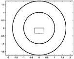
- FIG. 7shows a distribution diagram of a light source of an optomechanical in K-space according to an exemplary embodiment.
- FIG. 8shows a distribution diagram of a light source of an optomechanical in K-space after being coupled in according to an exemplary embodiment.
- FIG. 9shows a distribution diagram of the light source of the optomechanical in K space after being coupled out according to an exemplary embodiment.
- the distribution in K spaceis shown in the figure 8 shown.
- the period of inflection and outcoupling gratingis set to adjust the outcoupling center field of view to be output vertically from the optical waveguide lens, after one-dimensional surface relief inflection and outcoupling grating, at K
- the spatial distributionis shown in Figure 9. Since the grating vector sum of the optical waveguide mirror is not zero, the dispersion of the optical waveguide mirror is unavoidable (compare the distribution of Fig. 7).
- the visible light lasercan be used as the light source, and the dispersion of the optical waveguide lens can be limited by its narrow line width, so that the dispersion phenomenon cannot be observed by the human eye.
- the method for calculating the linewidth of the visible laseris the same, which is not repeated here and does not limit the present application.
- the light emitted by the objectpasses through the pupil of the human eye and is imaged on the retina through the refraction system of the human eye. Since the focal length of the human eye is only about 20mm, the diffraction pattern on the retina looks like a Fraunhofer aperture.
- the pupilis basically a circular hole, and its diameter is adjusted by the iris in the range of 2mm-8mm. Under normal brightness conditions, the pupil diameter is about 3mm.
- the most sensitive green light wavelength of the human eyeis 550nm, and the minimum resolution angle of the human eye is 550nm. is 1'.
- the field of view of the optomechanicalis 40°, which means that, in an optical instrument, with the lens of the optical instrument as the vertex, the angle formed by the two edges of the maximum range where the object image of the object to be measured can pass through the lens, This is called the field of view (FOV).
- the size of the field of viewdetermines the field of view of the optical instrument. The larger the field of view, the larger the field of view and the smaller the optical magnification. In layman's terms, if the target object exceeds this angle, it will not be included in the lens.
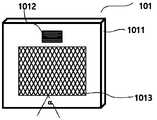
- FIG. 10shows a schematic perspective view of the turning and outcoupling grating being a two-dimensional grating according to an exemplary embodiment.
- the optical waveguide substrate 1011 of the optical waveguide sheet 101 and the coupling-in grating region 1012are one-dimensional surface relief gratings.
- the turning and coupling-out grating region 1013is a two-dimensional surface relief grating composed of two one-dimensional surface relief gratings, and the period of the two-dimensional grating in both directions is ⁇ 3 , and the included angle is ⁇ .
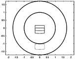
- FIG. 11shows a distribution diagram of a light source of an optomechanical in K-space according to another exemplary embodiment.
- FIG. 12shows a distribution diagram of a light source of an optomechanical in K-space after being coupled in according to another exemplary embodiment.
- FIG. 13shows a distribution diagram of the light source of the optomechanical in K space after the two-dimensional grating is coupled out according to an exemplary embodiment.
- the wavelength at half maximum widthis ⁇ 1
- the field of view of the optomechanicalis 40°
- the distribution of the optomechanical in K space at the center wavelengthis
- the period of the coupled gratingis set to ⁇ 1 , and its size is suitable to be just distributed in the ring.
- the distribution in K spaceis shown in Figure 12.
- the light sourceis coupled out through a two-dimensional grating, the period of the two-dimensional grating in both directions is ⁇ 3 , and the included angle is ⁇ , so that the out-coupling center field of view is perpendicular to the output of the optical waveguide lens, as shown in Figure 13.
- the required linewidth of the visible lasercan be calculated using the following formula: where ⁇ is the angular resolution of the human eye. Specifically, it can be taken as 1′. For AR glasses, 2′ is also acceptable.
- the angle ⁇10° between the optical-mechanical coupling and the surface normal of the optical waveguide lens .
- the line width of the visible light lasercan also be found to be 0.76 nm. It can be seen from this that the linewidth of the required visible light laser has nothing to do with the turning and coupling-out grating whether it is a one-dimensional grating or a two-dimensional grating.
- the method for calculating the linewidth of the visible laseris the same, which is not repeated here and cannot be regarded as a limitation of this application.
- the RGB three-layer optical waveguide sheetis superimposed in the direction perpendicular to the surface of the waveguide sheet in the order of blue light sheet, green light sheet and red light sheet (not shown in the figure).
- a cut-off filteris set between them so that the light of the cut-off wavelength does not pass.
- a blue light cutoff filteris set between the blue light sheet and the green light sheet, so that blue light does not pass; correspondingly, a green light cutoff filter is set between the green light sheet and the red light sheet, so that green light does not pass.
- the angle between the surface of the three-layer optical waveguide lens and the vertical directionis ⁇
- the angle between the optical-mechanical coupling direction and the surface normal of each layer of the optical waveguide lensis ⁇ .
- the minimum linewidth of the optomechanical visible light laseris generally 0.5nm. Under the condition that the linewidth of the optomechanical visible light laser is 0.5nm, the optomechanical inclination angle range can be 0-15°, and the inclination angle should not be too large, otherwise it will lead to Image is distorted.
- FIG. 14illustrates a side view of an optical machine coupled with at least one layer of optical waveguide optic in a non-perpendicular manner, according to an example embodiment.
- the coupling-in period, turning and coupling-out period of the gratingare different.
- different optical waveguide lensesare used to transmit light of different wavelengths.
- each layer of optical waveguide lenshas its own in-coupling period and inflection and out-coupling period corresponding to each color light.
- the turning and coupling out gratingmake the light in the center field of view of the optical machine transmitted through the optical waveguide lens and then coupled out of human beings
- the central field of view of the eyewhich needs to satisfy in The vertical center line is set clockwise as positive, and ⁇ can be negative, that is, the optical waveguide lens 101 rotates the angle ⁇ counterclockwise with the vertical center line, that is, the corresponding optical waveguide lens is inclined toward the eye side.
- Figure 15shows a side view of an opto-mechanical coupled to a three-layer RGB optical waveguide sheet in a non-perpendicular manner according to another example embodiment.
- the coupling-in period, turning and coupling-out period of the gratingare different.
- different optical waveguide lensesare used to transmit light of different wavelengths.
- each layer of optical waveguide lenshas its own in-coupling period and inflection and out-coupling period corresponding to each color light.
- the coupling grating period ⁇ 1460nm
- the coupling-in period and turning and coupling-out period of the gratingare different.
- different optical waveguide lensesare used to transmit light of different wavelengths.
- each layer of optical waveguide lenshas its own in-coupling period and inflection and coupling-out period corresponding to each color light.
- the coupling grating period ⁇ 1460nm
- the turning and coupling out gratingmake the light in the center field of view of the optical machine transmitted through the optical waveguide lens and then coupled out of In the central field of view of the human eye
- the corresponding turning and coupling-out gratingsare two-dimensional gratings.
- the coupling-in period, turning and coupling-out period of the gratingare different.
- different optical waveguide lensesare used to transmit light of different wavelengths.
- each layer of optical waveguide lenshas its own in-coupling period and inflection and out-coupling period corresponding to each color light.
- the coupling grating period ⁇ 1500nm
- the coupling-in period, turning and coupling-out period of the gratingare different.
- different optical waveguide lensesare used to transmit light of different wavelengths.
- each layer of optical waveguide sheethas its own in-coupling period and inflection and coupling-out period corresponding to each color light.
- the coupling grating period ⁇ 1510nm
- the turning and coupling grating period ⁇ 2483.3 nm
- the present applicationprovides an augmented reality display device, and solves the problem of dispersion existing in the optical waveguide lens, and the use of a light source with a narrow line width can prevent the human eye from observing the dispersion phenomenon. , and a detailed and feasible description of satisfying the conditions is made in the embodiment.
- the optical-mechanical and optical waveguide lensescan still ensure that the optical-mechanical central field of view and the human eye's central field of view overlap in the case of non-vertical coupling, which greatly improves the structural design of the optical-mechanical and optical waveguide lenses degrees of freedom.
Landscapes
- Physics & Mathematics (AREA)
- General Physics & Mathematics (AREA)
- Optics & Photonics (AREA)
- Engineering & Computer Science (AREA)
- Computer Graphics (AREA)
- Computer Hardware Design (AREA)
- General Engineering & Computer Science (AREA)
- Software Systems (AREA)
- Theoretical Computer Science (AREA)
- Optical Couplings Of Light Guides (AREA)
- Diffracting Gratings Or Hologram Optical Elements (AREA)
- Optical Integrated Circuits (AREA)
Abstract
Description
Translated fromChinese本申请涉及增强现实技术领域,具体而言,涉及一种增强现实的显示设备。The present application relates to the technical field of augmented reality, and in particular, to an augmented reality display device.
目前,增强现实技术即AR(Augmented Reality)技术是将虚拟信息与现实世界相互融合,以增强现实眼镜为代表的增强现实技术目前在各个行业开始兴起,尤其在安防和工业领域,增强现实技术体现了无与伦比的优势,大大改进了信息交互方式。目前比较成熟的增强现实技术主要分为棱镜方案、birdbath方案、自由曲面方案、离轴全息透镜方案和波导(Lightguide)方案,前三种方案体积较大,限制了其在智能穿戴方面,即增强现实眼镜方面的应用。全息透镜方案使用全息片独一无二的光学特性,具有大视场角(FOV)和小体积的优势,但是受限于眼动范围比较小,且全息波导方案在色彩均匀性(无彩虹效应)和实现单片全彩波导上均有优势,但是目前在大规模量产和大视场上受到了限制。波导是目前最佳的增强现实眼镜方案。波导方案又分为几何波导方案、浮雕光栅波导方案和体全息波导方案。几何波导方案中一般包括锯齿结构波导和偏振薄膜阵列反射镜波导(简称偏振阵列波导)。其中主流的偏振阵列波导是使用阵列的部分透射部分反射薄膜镜来达到虚拟信息的显示的目的,偏振阵列波导方案具有轻薄、眼动范围大且色彩均匀的优势。浮雕光栅波导方案可以用纳米压印工艺进行大批量生产,它具有大视场和大眼动范围的优势,但是也会带来视场均匀性和色彩均匀性的挑战,同时相关的微纳加工工艺也是巨大的挑战。At present, augmented reality technology, or AR (Augmented Reality) technology, integrates virtual information with the real world. Augmented reality technology represented by augmented reality glasses is currently emerging in various industries, especially in the security and industrial fields. Augmented reality technology reflects It has an unparalleled advantage and greatly improves the way of information interaction. At present, the more mature augmented reality technologies are mainly divided into prism solution, birdbath solution, free-form surface solution, off-axis holographic lens solution and waveguide (Lightguide) solution. Applications in Reality Glasses. The holographic lens scheme uses the unique optical characteristics of holograms, which has the advantages of large field of view (FOV) and small volume, but is limited by the relatively small eye movement range, and the holographic waveguide scheme has advantages in color uniformity (no rainbow effect) and realization of Monolithic full-color waveguides have advantages, but are currently limited in mass production and large fields of view. Waveguides are currently the best solution for augmented reality glasses. The waveguide scheme is further divided into geometric waveguide scheme, relief grating waveguide scheme and volume holographic waveguide scheme. The geometric waveguide scheme generally includes a sawtooth structure waveguide and a polarizing film array mirror waveguide (abbreviated as polarized array waveguide). Among them, the mainstream polarized arrayed waveguide uses a partially transmissive and partially reflective film mirror of the array to display virtual information. The polarized arrayed waveguide solution has the advantages of lightness, thinness, large eye movement range and uniform color. The relief grating waveguide solution can be mass-produced by nanoimprinting process. It has the advantages of large field of view and large eye movement range, but it also brings challenges of field of view uniformity and color uniformity. At the same time, the related micro-nano processing The craftsmanship is also a huge challenge.
发明人发现,通常若要使光机的中心视场与人眼中心视场重合,光机需与光波导镜片垂直耦入,这种方式使得结构设计的自由度较低。受光波导镜片和光机本身限制,耦出图像光线的视场较小。The inventor found that, in order to make the central field of view of the optomechanical coincide with the central field of view of the human eye, the optomechanical needs to be vertically coupled with the optical waveguide lens, which makes the degree of freedom in structural design low. Limited by the optical waveguide lens and the optomechanical itself, the field of view coupled out of the image light is small.
在所述背景技术部分公开的上述信息仅用于加强对本申请的背景的理解,因此它可以包括不构成对本领域普通技术人员已知的现有技术的信息。The above information disclosed in this Background section is only for enhancement of understanding of the background of the application and therefore it may contain information that does not form the prior art that is already known to a person of ordinary skill in the art.
发明内容SUMMARY OF THE INVENTION
基于此,本申请提供了一种增强现实的显示设备,并针对光波导镜片存在的色散问题通过选择可见激光光源来解决。通过本申请的技术方案,使得光机与光波导镜片在非垂直耦入的情况下仍能保证光机中心视场与人眼中心视场重合,极大地提升了光机与光波导镜片结构设计的自由度。Based on this, the present application provides an augmented reality display device, and solves the problem of dispersion existing in the optical waveguide sheet by selecting a visible laser light source. Through the technical solution of the present application, the optical-mechanical and optical waveguide lenses can still ensure that the optical-mechanical central field of view and the human eye's central field of view overlap in the case of non-vertical coupling, which greatly improves the structural design of the optical-mechanical and optical waveguide lenses degrees of freedom.
本申请技术方案的特征和优点将通过下面的详细描述变得显然,或部分地通过本申请的实践而习得。The features and advantages of the technical solutions of the present application will become apparent from the following detailed description, or be learned in part by practice of the present application.
据本申请的一方面,提出一种增强现实的显示设备,包括:光机,用于发射图像光线;至少一层光波导镜片,用于耦入及转折与耦出光机发射的图像光线,至少一层光波导镜片包括,耦入光栅区、光波导基底和转折与耦出光栅区,其中,耦入光栅区设置在光波导基底的第一光学表面上,接收光机发射的传输图像光线;光波导基底,用于通过全反射传输图像光线;转折与耦出光栅区设置在光波导基底的第一光学表面上,接收光波导基底传输的全反射光并耦出;耦入光栅矢量和转折与耦出光栅矢量之和不为零,其中,光机与各层光波导镜片的耦入角度相同。According to one aspect of the present application, an augmented reality display device is proposed, comprising: an optical machine for emitting image light; at least one layer of optical waveguide lens for coupling in, turning in and out of the image light emitted by the optical machine, at least A layer of optical waveguide lens includes an in-coupling grating area, an optical waveguide substrate, and a turning and out-coupling grating area, wherein the in-coupling grating area is arranged on the first optical surface of the optical waveguide substrate and receives the transmitted image light emitted by the optical machine; The optical waveguide substrate is used to transmit the image light through total reflection; the turning and coupling-out grating area is arranged on the first optical surface of the optical waveguide substrate, and receives the total reflection light transmitted by the optical waveguide substrate and couples it out; the input grating vector sums the turning The sum of the vector with the out-coupling grating is not zero, wherein the coupling-in angle of the optical machine and each layer of the optical waveguide lens is the same.
根据一些实施例,各层光波导镜片对应一种颜色的图像光线。According to some embodiments, each layer of the optical waveguide sheet corresponds to one color of image light.
根据一些实施例,转折与耦出光栅区的光栅需满足如下公式:According to some embodiments, the gratings in the turning and out-coupling grating regions need to satisfy the following formula:

其中
根据一些实施例,光机与至少一层光波导镜片表面法线的夹角θ范围0°~15°。According to some embodiments, the included angle θ between the optical machine and the surface normal of the at least one layer of the optical waveguide sheet ranges from 0° to 15°.
根据一些实施例,至少一层光波导镜片表面与竖直方向的夹角γ与至少一层光波导镜片表面法线的夹角θ满足如下公式:According to some embodiments, the included angle γ between the surface of the at least one layer of the optical waveguide sheet and the vertical direction and the included angle θ between the surface normal of the at least one layer of the optical waveguide sheet satisfy the following formula:
θ+γ≤20°θ+γ≤20°
根据一些实施例,转折与耦出光栅区包括一维表面浮雕光栅或二维表面浮雕光栅。According to some embodiments, the turning and outcoupling grating region comprises a one-dimensional surface relief grating or a two-dimensional surface relief grating.
根据一些实施例,光机的光源传输图像光线包括可见激光,通过光源的窄线宽的特性限制光波导镜片的色散。According to some embodiments, the light source of the optomechanical transmits the image light rays including visible laser light, and the dispersion of the optical waveguide lens is limited by the narrow line width of the light source.
根据一些实施例,可见光激光的线宽、耦入光栅周期、转折与耦出光栅周期满足如下公式:According to some embodiments, the line width of the visible light laser, the period of the coupled-in grating, the turning and coupled-out grating periods, satisfy the following formulas:

其中ε为人眼的角分辨率,光机耦入方向与至少一层光波导镜片表面法线的夹角θ,耦入光栅周期Λ1,转折与耦出光栅周期Λ2,可见光激光的线宽δλ。where ε is the angular resolution of the human eye, the angle θ between the optical-mechanical coupling-in direction and the surface normal of the at least one layer of optical waveguide lens, the coupling-in grating period Λ1 , the turning and out-coupling grating period Λ2 , the line width of the visible light laser δλ.
根据一些实施例,当转折与耦出光栅区为二维表面浮雕光栅时,转折与耦出光栅沿两个方向的周期均为Λ3,夹角为α,可见光激光的线宽满足于如下公式:According to some embodiments, when the turning and coupling-out grating regions are two-dimensional surface relief gratings, the periods of the turning and coupling-out gratings in both directions are Λ3 , the included angle is α, and the line width of the visible laser satisfies the following formula :

其中ε为人眼的角分辨率,光机耦入方向与至少一层光波导镜片表面法线的夹角θ,传输图像光线的波长为λ。Among them, ε is the angular resolution of the human eye, the angle θ between the optical-mechanical coupling direction and the surface normal of the at least one layer of the optical waveguide lens, and the wavelength of the transmitted image light is λ.
根据一些实施例,光机发出RGB三色光;至少一层光波导镜片包括三层光波导镜片,每一层光波导镜片各自具有对应每种颜色光线的耦入周期和转折与耦出周期;耦入光栅矢量和转折与耦出光栅矢量之和不为零,其中,光机与三层光波导镜片的耦入角度均相同。According to some embodiments, the optical machine emits RGB three-color light; at least one layer of optical waveguide lens includes three layers of optical waveguide lens, each layer of optical waveguide lens has a coupling-in period and a turning and coupling-out period corresponding to each color light; The sum of the input grating vector and the turning point and the coupling-out grating vector is not zero, and the coupling angles of the optomechanical and the three-layer optical waveguide mirror are all the same.
根据一些实施例,光机发出RGB三色光,包括:According to some embodiments, the optomechanical emits RGB tricolor light, including:
蓝光的线宽范围在0-2.nm之间,可选范围在0-0.5nm之间;The linewidth range of blue light is between 0-2.nm, and the optional range is between 0-0.5nm;
绿光的线宽范围在0-2.3nm之间,可选范围在0-0.5nm之间;The line width of green light is between 0-2.3nm, and the optional range is between 0-0.5nm;
红光的线宽范围在0-2.7nm之间,可选范围在0-0.5nm之间。The linewidth of red light is in the range of 0-2.7nm, and the optional range is between 0-0.5nm.
根据一些实施例,光波导基底的厚度为0.3mm至2.5mm,折射率为1.4 全2.2。According to some embodiments, the optical waveguide substrate has a thickness of 0.3 mm to 2.5 mm and a refractive index of 1.4 to 2.2.
根据一些实施例,光波导基底透明且有固定厚度,具有两个相对的光学平面且材料包括玻璃或者石英。According to some embodiments, the optical waveguide substrate is transparent and of fixed thickness, has two opposing optical planes, and the material includes glass or quartz.
根据本申请的技术方案,提出光栅矢量和不为零的平面光波导镜片,使得光机与光波导镜片在非垂直耦入的情况下仍能保证光机中心视场与人眼中心视场重合,通过可见光激光器与光栅矢量和不为零的波导片这一组合极大地提升了光机与光波导镜片结构设计的自由度。According to the technical solution of the present application, a planar optical waveguide lens with a non-zero grating vector sum is proposed, so that the optical-mechanical and optical waveguide lenses can still ensure that the optical-mechanical center field of view and the human eye center field of view are coincident under the condition of non-vertical coupling. , through the combination of the visible light laser and the waveguide sheet whose grating vector sum is not zero, the freedom of structure design of the optical machine and the optical waveguide sheet is greatly improved.
应当理解的是,以上的一般描述和后文的细节描述仅是示例性的,并不能限制本申请。It is to be understood that the foregoing general description and the following detailed description are exemplary only and do not limit the application.
为了更清楚地说明本申请实施例中的技术方案,下面将对实施例描述中所需要使用的附图作简单地介绍,显而易见地,下面描述中的附图仅仅是本申请的一些实施例,对于本领域普通技术人员来讲,还可以根据这些附图获得其他的附图,而并不超出本申请要求保护的范围。In order to illustrate the technical solutions in the embodiments of the present application more clearly, the following briefly introduces the drawings that are used in the description of the embodiments. Obviously, the drawings in the following description are only some embodiments of the present application. For those of ordinary skill in the art, other drawings can also be obtained from these drawings without exceeding the scope of protection claimed in the present application.
图1示出根据一示例性实施例的增强现实显示设备的侧视图。FIG. 1 shows a side view of an augmented reality display device according to an exemplary embodiment.
图2示出根据一示例性实施例的光机与光波导镜片以垂直的方式耦合的侧视图。FIG. 2 shows a side view of an optical machine coupled with an optical waveguide sheet in a vertical manner according to an exemplary embodiment.
图3示出根据一示例性实施例的耦入光栅矢量和转折与耦出光栅矢量之和为零的示意图。FIG. 3 shows a schematic diagram of a coupled-in grating vector and the sum of the inflection and coupled-out grating vectors being zero, according to an exemplary embodiment.
图4示出根据一示例性实施例的光机与光波导镜片以非垂直的方式耦合的侧视图。4 illustrates a side view of an optical machine coupled with an optical waveguide mirror in a non-perpendicular manner, according to an exemplary embodiment.
图5示出根据一示例性实施例的耦入光栅矢量和转折与耦出光栅矢量之和不为零的示意图。FIG. 5 is a schematic diagram illustrating that the sum of the coupled-in grating vector and the inflection and coupled-out grating vectors is not zero, according to an exemplary embodiment.
图6示出根据另一示例性实施例的光机与光波导镜片以非垂直的方式耦合的侧视图。6 illustrates a side view of an optical machine coupled with an optical waveguide sheet in a non-perpendicular manner according to another exemplary embodiment.
图7示出根据一示例性实施例的光机的光源在K空间中的分布图。FIG. 7 shows a distribution diagram of a light source of an optomechanical in K-space according to an exemplary embodiment.
图8示出根据一示例性实施例的光机的光源耦入后在K空间中的分布图。FIG. 8 shows a distribution diagram of a light source of an optomechanical in K-space after being coupled in according to an exemplary embodiment.
图9示出根据一示例性实施例的光机的光源耦出后在K空间中的分布图。FIG. 9 shows a distribution diagram of the light source of the optomechanical in K space after being coupled out according to an exemplary embodiment.
图10示出根据一示例性实施例的转折与耦出光栅为二维光栅的立体示意图。FIG. 10 shows a schematic perspective view of the turning and outcoupling grating being a two-dimensional grating according to an exemplary embodiment.
图11示出根据另一示例性实施例的光机的光源在K空间中的分布图。FIG. 11 shows a distribution diagram of a light source of an optomechanical in K-space according to another exemplary embodiment.
图12示出根据一示例性实施例的光机的光源耦入后在K空间中的分布图。FIG. 12 shows a distribution diagram of a light source of an optomechanical in K-space after being coupled in according to an exemplary embodiment.
图13示出根据一示例性实施例的光机的光源耦出二维光栅后在K空间中的分布图。FIG. 13 shows a distribution diagram of the light source of the optomechanical in K space after the two-dimensional grating is coupled out according to an exemplary embodiment.
图14示出根据一示例实施例的光机与RGB三层光波导镜片以非垂直的方式耦合的侧视图。14 illustrates a side view of an opto-mechanical coupled with an RGB three-layer optical waveguide sheet in a non-perpendicular manner, according to an example embodiment.
图15示出根据另一示例实施例的光机与RGB三层光波导镜片以非垂直的方式耦合的侧视图。15 illustrates a side view of an opto-mechanical coupled to an RGB three-layer optical waveguide sheet in a non-perpendicular manner according to another example embodiment.
现在将参考附图更全面地描述示例实施例。然而,示例实施例能够以多种形式实施,且不应被理解为限于在此阐述的实施例;相反,提供这些实施例使得本申请将全面和完整,并将示例实施例的构思全面地传达给本领域的技术人员。在图中相同的附图标记表示相同或类似的部分,因而将省略对它们的重复描述。Example embodiments will now be described more fully with reference to the accompanying drawings. Example embodiments, however, can be embodied in various forms and should not be construed as limited to the embodiments set forth herein; rather, these embodiments are provided so that this application will be thorough and complete, and will fully convey the concept of example embodiments to those skilled in the art. The same reference numerals in the drawings denote the same or similar parts, and thus their repeated descriptions will be omitted.
所描述的特征、结构或特性可以以任何合适的方式结合在一个或更多实施例中。在下面的描述中,提供许多具体细节从而给出对本公开的实施例的充分理解。然而,本领域技术人员将意识到,可以实践本公开的技术方案而没有这些特定细节中的一个或更多,或者可以采用其它的方式、组元、材料、装置等。在这些情况下,将不详细示出或描述公知结构、方法、装置、实现步骤、材料或者操作。The described features, structures, or characteristics may be combined in any suitable manner in one or more embodiments. In the following description, numerous specific details are provided in order to give a thorough understanding of the embodiments of the present disclosure. However, those skilled in the art will appreciate that the technical solutions of the present disclosure may be practiced without one or more of these specific details, or with other ways, components, materials, devices, etc. In these instances, well-known structures, methods, devices, implementations, materials, or operations are not shown or described in detail.
此外,术语“包括”和“具有”以及它们任何变形,意图在于覆盖不排他的包含。例如包含了一系列步骤或单元的过程、方法、系统、产品或设备没有限定于已列出的步骤或单元,而是可选地还包括没有列出的步骤或单元,或可选地还包括对于这些过程、方法、产品或设备固有的其他步 骤或单元。Furthermore, the terms "comprising" and "having" and any variations thereof are intended to cover non-exclusive inclusion. For example, a process, method, system, product or device comprising a series of steps or units is not limited to the listed steps or units, but optionally also includes unlisted steps or units, or optionally also includes For other steps or units inherent to these processes, methods, products or devices.
本申请的说明书和权利要求书及上述附图中的术语“第一”、“第二”等是用于区别不同对象,而不是用于描述特定顺序。此外,术语“包括”和“具有”以及它们任何变形,意图在于覆盖不排他的包含。The terms "first", "second" and the like in the description and claims of the present application and the above drawings are used to distinguish different objects, rather than to describe a specific order. Furthermore, the terms "comprising" and "having" and any variations thereof are intended to cover non-exclusive inclusion.
图1示出根据一示例性实施例的增强现实显示设备的侧视图。FIG. 1 shows a side view of an augmented reality display device according to an exemplary embodiment.
目前已知的增强现实显示设备100,如图1所示。包括一光波导镜片101,一光机102。光波导镜片101包括一光波导基底1011,一耦入光栅区1012,一转折与耦出光栅区1013。耦入光栅区为一维表面浮雕光栅。转折与耦出光栅区可以是一维表面浮雕光栅,也可以是二维表面浮雕光栅。A currently known augmented reality display device 100 is shown in FIG. 1 . It includes an
根据实施例,来自光机102的图像光线经过耦入光栅区1012后,衍射光被光波导基底1011全反射传输至转折与耦出光栅区1013,最终被衍射至人眼103,其中耦入光栅矢量和转折与耦出光栅矢量之和不为零,光机与各层光波导镜片的耦入角度相同。According to the embodiment, after the image light from the optomechanical 102 passes through the coupling-in
光波导基底1011对可见光透明,具有两个相对的光学平面,用于全反射传输图像光线。可选地,光波导基底1011的厚度为0.3mm至2.5mm,折射率为1.4至2.2(目前市售光学材料的折射率一般在该范围内),光波导基底的材料包括玻璃或者石英。The
根据已知的理论特性,本申请中的波导基底1011以厚度轻薄、大折射率为宜。利用全反射原理,可以使满足条件的光机打进去的光产生全反射,就能实现将光从光机搬运到人眼睛前面的任务。According to the known theoretical characteristics, the
已知的增强现实显示设备100,实现了把眼睛周围很庞大的光机搬到旁边去,比如在侧面、额头处,可以不挡住视线,通过光波导镜片101这样一个传输的媒介,再把光带到眼睛前面来。The known augmented reality display device 100 realizes that the huge optical machine around the eyes can be moved to the side, such as on the side or the forehead, without blocking the line of sight, through a transmission medium such as the
另外一个比较大的优点就是,可以增大动眼眶(戴上眼镜之后,眼睛在系统中心点周围移动多大的x和y的范围仍然能够清晰地看到图像)的范围,所以增大动眼眶的范围,使得在做产品时更加容易适应所有的人群。Another big advantage is that it can increase the range of the orbit (after wearing glasses, how much the eye moves around the center point of the system in the range of x and y to still be able to see the image clearly), so increase the orbit of the eye. The range makes it easier to adapt to all groups of people when making products.
当然也有一些不足,比如光学效率相对较低,对于衍射波导来说会有一些色散导致的彩虹现象以及色彩不均匀,出现明暗交替的光线。通常若要使光机的中心视场与人眼中心视场重合,光机需与光波导镜片垂直耦入, 这种方式使得结构设计的自由度较低。Of course, there are also some shortcomings, such as relatively low optical efficiency, and for diffractive waveguides, there will be some rainbow phenomenon caused by dispersion and uneven color, and light and dark alternating light will appear. Usually, in order to make the central field of view of the optomechanical coincide with the central field of view of the human eye, the optomechanical needs to be coupled vertically with the optical waveguide lens, which makes the degree of freedom of structural design low.
图2示出根据一示例性实施例的光机与光波导镜片以垂直的方式耦合的侧视图。FIG. 2 shows a side view of an optical machine coupled with an optical waveguide sheet in a vertical manner according to an exemplary embodiment.
如图2所示,通常光机与光波导镜片垂直耦合,这样可以使得光机的中心视场对应人眼观察到的中心视场,然而垂直耦合布局这就限制了光机与光波导镜片布局的自由度,不利于AR眼镜的结构设计。如果光机与光波导镜片以非垂直的方式耦合,为了使人眼观察到的中心视场与光机的中心视场重合,则人眼与光波导镜片将不平行(参见图4),这会影响用户的观察体验。As shown in Figure 2, usually the opto-mechanical and the optical waveguide lens are vertically coupled, so that the central field of view of the opto-mechanical corresponds to the central field of view observed by the human eye. However, the vertical coupling layout limits the layout of the opto-mechanical and the optical waveguide lens. The degree of freedom is not conducive to the structural design of AR glasses. If the optical machine and the optical waveguide lens are coupled in a non-perpendicular manner, in order to make the central field of view observed by the human eye coincide with the central field of view of the optical machine, the human eye and the optical waveguide lens will not be parallel (see Figure 4). It will affect the user's viewing experience.
图3示出根据一示例性实施例的耦入光栅矢量和转折与耦出光栅矢量之和示意图。FIG. 3 shows a schematic diagram of the coupled-in grating vector and the sum of the inflection and coupled-out grating vectors according to an exemplary embodiment.
如图3所示,一般来说,光波导镜片设计中,耦入光栅矢量和转折与耦出光栅矢量之和为0,即,耦入光栅矢量


根据实施例,当转折与耦出光栅区为一维表面浮雕光栅时,对应的光栅矢量指转折光栅矢量与耦出光栅矢量的矢量和,当转折与耦出光栅区为二维表面浮雕光栅时,对应的光栅矢量指该二维表面浮雕光栅的光栅矢量。According to the embodiment, when the turning and outcoupling grating regions are one-dimensional surface relief gratings, the corresponding grating vector refers to the vector sum of the turning grating vectors and the outcoupling grating vectors, and when the turning and outcoupling grating regions are two-dimensional surface relief gratings , and the corresponding grating vector refers to the grating vector of the two-dimensional surface relief grating.
常用的浮雕光栅主要有一维光栅,其包括倾斜光栅、梯形光栅、闪耀光栅和矩形光栅结构等。二维光栅,如波导中常用的六边形分布的圆柱光栅结构以上光栅结构的特征尺寸均为纳米级。所以目前浮雕光栅波导的路线主要有:基于一维光栅的浮雕光栅波导方案,原理图如图1所示,分为耦入、转折和耦出区域,三个区域均采用一维光栅,并在转折区域和耦出区域分别进行一个方向的扩展。Commonly used relief gratings are mainly one-dimensional gratings, which include tilted gratings, trapezoidal gratings, blazed gratings, and rectangular gratings. For two-dimensional gratings, such as the hexagonally distributed cylindrical grating structure commonly used in waveguides, the characteristic dimensions of the above grating structures are all nanoscale. Therefore, the current routes of the relief grating waveguide mainly include: the one-dimensional grating-based relief grating waveguide scheme. The schematic diagram is shown in Figure 1. It is divided into coupling-in, turning and coupling-out regions. The turning region and the coupling-out region expand in one direction respectively.
基于二维光栅的浮雕光栅波导方案,分为耦入和耦出区域,耦入区域经典结构为一维光栅,耦出区域结构为二维光栅(图未示出),使用二维光栅结构的多个级次,同时保证光束的耦出和多个方向的扩展。通过模拟计算二维光栅波导的K域图(参见图11至图13),圆环内代表光在波导片中满足全反射条件,外圈代表波导片材料所可以达到得最大K值,耦入光栅将光束的K值平移到环形区域,即使得光束满足在波导片内全反射传播得条件,耦出光栅将部分光束的K值从环形区域平移到内圈区域,即使得光束耦出到 人眼。The two-dimensional grating-based relief grating waveguide scheme is divided into coupling-in and coupling-out regions. The classical structure of the coupling-in region is a one-dimensional grating, and the coupling-out region structure is a two-dimensional grating (not shown in the figure). Multiple levels, while ensuring the outcoupling of the beam and the expansion in multiple directions. The K-domain diagram of the two-dimensional grating waveguide is calculated by simulation (see Figure 11 to Figure 13). The inner circle represents that the light meets the condition of total reflection in the waveguide sheet, and the outer circle represents the maximum K value that the material of the waveguide sheet can achieve. The grating translates the K value of the beam to the annular area, that is, the beam satisfies the condition of total reflection and propagation in the waveguide plate, and the coupling-out grating translates the K value of part of the beam from the annular area to the inner ring area, that is, the beam is coupled out to the human Eye.
此时,在透射情况下,耦出至人眼的光线与光机耦入光波导镜片的光线方向一致;在反射情况下,耦出至人眼的光线与光机耦入光波导镜片的光线方向关于光波导镜片表面的法线呈镜像对称。At this time, in the case of transmission, the light coupled out to the human eye is in the same direction as the light coupled into the optical waveguide lens by the opto-mechanical; in the case of reflection, the light coupled out to the human eye is the same as the light coupled into the optical waveguide lens by the opto-mechanical The directions are mirror-symmetrical with respect to the normal to the surface of the optical waveguide lens.
图5示出根据一示例性实施例的耦入光栅矢量和转折与耦出光栅矢量之和不为零的示意图。FIG. 5 is a schematic diagram illustrating that the sum of the coupled-in grating vector and the inflection and coupled-out grating vectors is not zero, according to an exemplary embodiment.
如图5所示,当耦入光栅和转折与耦出光栅的光栅矢量之和不为零,即,耦入光栅矢量


此时由于光波导镜片光栅矢量和不为零,会存在色散问题,而采用窄线宽的光源可以使得人眼无法观察到色散现象。不影响光波导镜片成像质量的线宽可以按以下描述方式求得。At this time, since the grating vector sum of the optical waveguide lens is not zero, there will be a problem of dispersion, and the use of a light source with a narrow line width can make the dispersion phenomenon impossible to be observed by the human eye. The line width that does not affect the imaging quality of the optical waveguide lens can be obtained in the following manner.
图7示出根据一示例性实施例的光机的光源在K空间中的分布图。FIG. 7 shows a distribution diagram of a light source of an optomechanical in K-space according to an exemplary embodiment.
图8示出根据一示例性实施例的光机的光源耦入后在K空间中的分布图。FIG. 8 shows a distribution diagram of a light source of an optomechanical in K-space after being coupled in according to an exemplary embodiment.
图9示出根据一示例性实施例的光机的光源耦出后在K空间中的分布图。FIG. 9 shows a distribution diagram of the light source of the optomechanical in K space after being coupled out according to an exemplary embodiment.
参见图7至图9,光机的光源在K空间中的分布(参见图7),根据实施例,针对转折与耦出光栅为一维表面浮雕光栅时的情况,设定光机耦入时与光波导镜片表面法线的夹角θ=10°,光源的中心波长为λc=460nm,半高宽波长为λ1,光机的视场角为40°,光波导镜片的折射率为n=1.7216,耦入光栅的周期设置为Λ1,其大小使得其刚好分布在环中为宜,光机输出的光经过耦入一维表面浮雕光栅之后,在K空间中的分布,如图8所示。Referring to FIGS. 7 to 9 , the distribution of the light source of the opto-mechanical in K space (see FIG. 7 ), according to the embodiment, for the case where the turning and coupling-out gratings are one-dimensional surface relief gratings, set the time of opto-mechanical coupling in The included angle θ=10° with the surface normal of the optical waveguide lens, the central wavelength of the light source is λc =460nm, the wavelength at half maximum width is λ1 , the field angle of the optical machine is 40°, and the refractive index of the optical waveguide lens is n=1.7216, the period of the coupled grating is set to Λ1 , and its size is suitable to be just distributed in the ring. After the light output by the optomechanical is coupled into the one-dimensional surface relief grating, the distribution in K space is shown in the figure 8 shown.
经过一维表面浮雕转折与耦出光栅,转折与耦出光栅的周期设置为,将耦出中心视场调整成从光波导镜片垂直输出,经过一维表面浮雕转折与耦出光栅之后,在K空间的分布如图9所示。由于光波导镜片的光栅矢量 和不为零,所以光波导镜片的色散不可避免(比较图7的分布)。After one-dimensional surface relief inflection and outcoupling grating, the period of inflection and outcoupling grating is set to adjust the outcoupling center field of view to be output vertically from the optical waveguide lens, after one-dimensional surface relief inflection and outcoupling grating, at K The spatial distribution is shown in Figure 9. Since the grating vector sum of the optical waveguide mirror is not zero, the dispersion of the optical waveguide mirror is unavoidable (compare the distribution of Fig. 7).
根据实施例,可以通过采用可见光激光器作为光源,利用其窄线宽的特性限制光波导镜片的色散,从而使得人眼无法观察到色散现象。所需可见光激光器的线宽可以通过如下公式计算,
当光源发出RGB三色光时,计算可见激光器线宽的方法相同,此处不做赘述且不限制本申请。When the light source emits RGB three-color light, the method for calculating the linewidth of the visible laser is the same, which is not repeated here and does not limit the present application.
具体地,物体发出的光线通过人眼的瞳孔,经人眼的折射系统成像于视网膜上。由于人眼的焦距只有20mm左右,故视网膜上的像是夫琅禾费圆孔衍射图样。瞳孔基本上是圆孔,其直径由虹膜在2mm-8mm范围内调节,在正常的光亮度条件下,瞳孔直径大约为3mm,人眼最敏感的绿光波长为550nm,人眼的最小分辨角为1′。Specifically, the light emitted by the object passes through the pupil of the human eye and is imaged on the retina through the refraction system of the human eye. Since the focal length of the human eye is only about 20mm, the diffraction pattern on the retina looks like a Fraunhofer aperture. The pupil is basically a circular hole, and its diameter is adjusted by the iris in the range of 2mm-8mm. Under normal brightness conditions, the pupil diameter is about 3mm. The most sensitive green light wavelength of the human eye is 550nm, and the minimum resolution angle of the human eye is 550nm. is 1'.
具体地,光机的视场角为40°理解为,在光学仪器中,以光学仪器的镜头为顶点,以被测目标的物像可通过镜头的最大范围的两条边缘构成的夹角,称为视场角(FOV)。视场角的大小决定了光学仪器的视野范围,视场角越大,视野就越大,光学倍率就越小。通俗地说,目标物体超过这个角就不会被收在镜头里。Specifically, the field of view of the optomechanical is 40°, which means that, in an optical instrument, with the lens of the optical instrument as the vertex, the angle formed by the two edges of the maximum range where the object image of the object to be measured can pass through the lens, This is called the field of view (FOV). The size of the field of view determines the field of view of the optical instrument. The larger the field of view, the larger the field of view and the smaller the optical magnification. In layman's terms, if the target object exceeds this angle, it will not be included in the lens.
图10示出根据一示例性实施例的转折与耦出光栅为二维光栅的立体示意图。FIG. 10 shows a schematic perspective view of the turning and outcoupling grating being a two-dimensional grating according to an exemplary embodiment.
如图10,根据实施例,光波导镜片101的光波导基底1011,耦入光栅区1012为一维表面浮雕光栅。转折与耦出光栅区1013是二维表面浮雕光栅,该二维表面浮雕光栅由两个一维表面浮雕光栅组成且二维光栅沿两个方向的周期均为Λ3,夹角为α。As shown in FIG. 10 , according to an embodiment, the
图11示出根据另一示例性实施例的光机的光源在K空间中的分布图。FIG. 11 shows a distribution diagram of a light source of an optomechanical in K-space according to another exemplary embodiment.
图12示出根据另一示例性实施例的光机的光源耦入后在K空间中的分布图。FIG. 12 shows a distribution diagram of a light source of an optomechanical in K-space after being coupled in according to another exemplary embodiment.
图13示出根据一示例性实施例的光机的光源耦出二维光栅后在K空间中的分布图。FIG. 13 shows a distribution diagram of the light source of the optomechanical in K space after the two-dimensional grating is coupled out according to an exemplary embodiment.
参见图11至图13,根据实施例,针对转折与耦出光栅为二维光栅时的情况,设定光机耦入时与光波导镜片表面法线的夹角θ=10°,光源的中心波长为λc=460nm,半高宽波长为λ1,光机的视场角为40°,光波导镜片的折射率为n=1.7216,在中心波长下光机在K空间中的分布。Referring to FIGS. 11 to 13 , according to the embodiment, for the case where the turning and coupling-out gratings are two-dimensional gratings, the angle θ=10° between the optical-mechanical coupling and the surface normal of the optical waveguide sheet is set, and the center of the light source is The wavelength is λc =460nm, the wavelength at half maximum width is λ1 , the field of view of the optomechanical is 40°, the refractive index of the optical waveguide lens is n=1.7216, and the distribution of the optomechanical in K space at the center wavelength.
耦入光栅的周期设置为Λ1,其大小使得其刚好分布在环中为宜,光机输出的光经过耦入光栅之后,在K空间中的分布,如图12所示。光源耦出经过二维光栅,二维光栅沿两个方向的周期均为Λ3,夹角为α,使得耦出中心视场垂直于光波导镜片输出,如图13所示。所需可见光激光的线宽可以用下式计算:
当光源发出RGB三色光时,计算可见激光器线宽的方法相同,此处不做赘述且不能作为本申请的限制。When the light source emits RGB three-color light, the method for calculating the linewidth of the visible laser is the same, which is not repeated here and cannot be regarded as a limitation of this application.
根据以上光波导镜片光栅矢量和不为零,会存在色散问题,通过实验得到的K空间分布图,并根据已知设定条件和参数计算出可见光激光器线宽使得人眼无法观察到色散现象。According to the above optical waveguide lens grating vector sum is not zero, there will be a dispersion problem. The K-space distribution map obtained by the experiment, and the linewidth of the visible laser is calculated according to the known setting conditions and parameters, so that the dispersion phenomenon cannot be observed by the human eye.
下面将根据实施例进一步地说明。The following will further illustrate according to the embodiment.
根据实施例,RGB三层光波导镜片按照蓝光片、绿光片和红光片的顺序在垂直波导片表面的方向叠加(图未示出),可选地,可在每层光波导镜片之间设置截止滤光片,使得被截止波长的光不通过。具体地,在蓝光片和 绿光片之间设置蓝光截止滤光片,使得蓝光不通过;对应的,绿光片和红光片之间设置绿光截止滤光片,使得绿光不通过。三层光波导镜片表面与竖直方向的夹角都为γ,光机耦入方向与各层光波导镜片表面法线的夹角都为θ。选用折射率均为n=1.72的光波导镜片基底材料,光机的主波长为460nm,530nm,620nm。目前光机可见光激光器的线宽最小值一般为0.5nm,在满足光机可见光激光器线宽为0.5nm的情况下,光机的倾角范围可以为0-15°,倾角不宜过大,否则会导致图像扭曲。According to the embodiment, the RGB three-layer optical waveguide sheet is superimposed in the direction perpendicular to the surface of the waveguide sheet in the order of blue light sheet, green light sheet and red light sheet (not shown in the figure). A cut-off filter is set between them so that the light of the cut-off wavelength does not pass. Specifically, a blue light cutoff filter is set between the blue light sheet and the green light sheet, so that blue light does not pass; correspondingly, a green light cutoff filter is set between the green light sheet and the red light sheet, so that green light does not pass. The angle between the surface of the three-layer optical waveguide lens and the vertical direction is γ, and the angle between the optical-mechanical coupling direction and the surface normal of each layer of the optical waveguide lens is θ. The base material of the optical waveguide lens with the refractive index of n=1.72 is selected, and the main wavelengths of the optical machine are 460 nm, 530 nm and 620 nm. At present, the minimum linewidth of the optomechanical visible light laser is generally 0.5nm. Under the condition that the linewidth of the optomechanical visible light laser is 0.5nm, the optomechanical inclination angle range can be 0-15°, and the inclination angle should not be too large, otherwise it will lead to Image is distorted.
以下根据实施例的说明包含的如上条件的实施例并不能限制本申请。The examples under the above conditions contained in the following description according to the examples do not limit the present application.
图14示出根据一示例实施例的光机与至少一层光波导镜片以非垂直的方式耦合的侧视图。14 illustrates a side view of an optical machine coupled with at least one layer of optical waveguide optic in a non-perpendicular manner, according to an example embodiment.
如图14所示,本实施例中光机与光波导镜片表面法线的夹角θ=10°,光波导镜片表面与竖直方向的夹角γ=5°,此时θ+γ不宜超过20°,如果可见光激光器线宽进一步降低,该限制可以放宽。针对不同波长的光,光栅的耦入周期和转折与耦出周期不同,一般以不同的光波导镜片传输不同波长的光,当光机发出的光由RGB三色组成时,三层光波导镜片作为传输介质,每一层光波导镜片各自具有对应每种颜色光线的耦入周期和转折与耦出周期,本实施例以λ=460nm的蓝光为例,红光和绿光可同理得出,此处不在赘述。为了使耦入光线能都在光波导镜片基底中满足全反射传输,设置耦入光栅周期Λ1=460nm,转折与耦出光栅使得光机中心视场的光线经过光波导镜片传输后耦出于人眼的中心视场,需满足


图15示出根据另一示例实施例的光机与三层RGB光波导镜片以非 垂直的方式耦合的侧视图。Figure 15 shows a side view of an opto-mechanical coupled to a three-layer RGB optical waveguide sheet in a non-perpendicular manner according to another example embodiment.
如图15所示,本实施例中光机与波导片表面法线的夹角θ=10°,波导片竖直设置光波导镜片表面与竖直方向的夹角γ=0°,此时θ+γ不宜超过20°,如果可见光激光器线宽进一步降低,该限制可以放宽。针对不同波长的光,光栅的耦入周期和转折与耦出周期不同,一般以不同的光波导镜片传输不同波长的光,当光机发出的光由RGB三色组成时,三层光波导镜片作为传输介质,每一层光波导镜片各自具有对应每种颜色光线的耦入周期和转折与耦出周期,本实施例以λ=460nm的蓝光为例,红光和绿光可同理得出。为了使耦入光线能都在光波导镜片基底中满足全反射传输,设置耦入光栅周期Λ1=460nm,转折与耦出光栅使得光机中心视场的光线经过光波导镜片传输后耦出于人眼的中心视场,需满足


继续参照图15,本实施例中光机与波导片表面法线的夹角θ=10°,波导片竖直设置光波导镜片表面与竖直方向的夹角γ=0°,此时θ+γ不宜超过20°,如果可见光激光器线宽进一步降低,该限制可以放宽。针对不同波长的光,光栅的耦入周期和转折与耦出周期不同,一般以不同的光波导镜片传输不同波长的光,当光机发出的光由RGB三色组成时,三层光波导镜片作为传输介质,每一层光波导镜片各自具有对应每种颜色光线的耦入周期和转折与耦出周期,本实施例以λ=460nm的蓝光为例,红光和绿光可同理得出,此处不做赘述。为了使耦入光线能都在光波导镜片基底中满足全反射传输,设置耦入光栅周期Λ1=460nm,转折与耦出光栅使得光机中心视场的光线经过光波导镜片传输后耦出于人眼的中心视场,对应的转折与耦出光栅为二维光栅,该二维光栅由两个一维光栅组成,每个的周期为Λ3=337nm,二者夹角为52°。Continuing to refer to FIG. 15 , in this embodiment, the angle θ=10° between the optical machine and the surface normal of the waveguide sheet, and the angle γ=0° between the surface of the optical waveguide sheet and the vertical direction is set vertically on the waveguide sheet, at this time θ+ γ should not exceed 20°, and this restriction can be relaxed if the visible laser linewidth is further reduced. For light of different wavelengths, the coupling-in period and turning and coupling-out period of the grating are different. Generally, different optical waveguide lenses are used to transmit light of different wavelengths. When the light emitted by the optical machine is composed of RGB three colors, the three-layer optical waveguide lens As a transmission medium, each layer of optical waveguide lens has its own in-coupling period and inflection and coupling-out period corresponding to each color light. In this embodiment, blue light with λ=460 nm is taken as an example, and red light and green light can be obtained in the same way. , will not be repeated here. In order to make the coupled light can meet the total reflection transmission in the optical waveguide lens substrate, set the coupling grating period Λ1 =460nm, the turning and coupling out grating make the light in the center field of view of the optical machine transmitted through the optical waveguide lens and then coupled out of In the central field of view of the human eye, the corresponding turning and coupling-out gratings are two-dimensional gratings. The two-dimensional grating consists of two one-dimensional gratings, each with a period of Λ3 =337 nm, and an included angle of 52°.
继续参照图15,本实施例中光机与波导片表面法线的夹角θ=15°,波 导片竖直设置,光波导镜片表面与竖直方向的夹角γ=0°,此时θ+γ不宜超过20°,如果可见光激光器线宽进一步降低,该限制可以放宽。针对不同波长的光,光栅的耦入周期和转折与耦出周期不同,一般以不同的光波导镜片传输不同波长的光,当光机发出的光由RGB三色组成时,三层光波导镜片作为传输介质,每一层光波导镜片各自具有对应每种颜色光线的耦入周期和转折与耦出周期,本实施例以λ=460nm的蓝光为例,红光和绿光可同理得出,此处不做赘述。为了使耦入光线能都在光波导镜片基底中满足全反射传输,设置耦入光栅周期Λ1=500nm,转折与耦出光栅使得光机中心视场的光线经过光波导镜片传输后耦出于人眼的中心视场,需满足

继续参照图15,根据实施例,光机与波导片表面法线的夹角θ=3.83°,波导片竖直设置光波导镜片表面与竖直方向的夹角为γ=0°,此时θ+γ不宜超过20°,如果可见光激光器线宽进一步降低,该限制可以放宽。针对不同波长的光,光栅的耦入周期和转折与耦出周期不同,一般以不同的光波导镜片传输不同波长的光,当光机发出的光由RGB三色组成时,三层光波导镜片作为传输介质,每一层光波导镜片各自具有对应每种颜色光线的耦入周期和转折与耦出周期,本实施例以λ=460nm的蓝光为例,为了使耦入光线能都在光波导镜片基底中满足全反射传输,设置耦入光栅周期Λ1=400nm,转折与耦出光栅使得光机中心视场的光线经过光波导镜片传输后耦出于人眼的中心视场,对应的转折与耦出光栅Λ2=378nm,则根据所需激光器的线宽计算,
同理可算出当红光波长λ=620nm,为了使耦入光线能都在光波导镜片基底中满足全反射传输,设置耦入光栅周期Λ1=510nm,设置转折与耦出光栅周期Λ2=483.3nm,则计算出对应的激光器线宽为δλ=2.7nm。In the same way, it can be calculated that the wavelength of red light is λ=620nm. In order to make the coupled light can meet the total reflection transmission in the optical waveguide lens substrate, set the coupling grating period Λ1 =510nm, set the turning and coupling grating period Λ2 =483.3 nm, the corresponding laser line width is calculated as δλ=2.7nm.
表格1示出,根据实施例的以蓝光λ=460nm的在不同夹角和光栅周期下满足激光器线宽范围为0~2nm,可选范围小于等于0.5nm。Table 1 shows that according to the embodiment, the blue light λ=460 nm satisfies the laser line width range of 0-2 nm under different included angles and grating periods, and the optional range is less than or equal to 0.5 nm.

红光和绿光的统计数据按照如上方式在此不赘述。The statistical data of the red light and the green light are as described above and will not be repeated here.
通过本申请的实施例的技术方案,本申请提供了一种增强现实的显示设备,并针对光波导镜片存在的色散问题,而采用窄线宽的光源可以使得人眼无法观察到色散现象来解决,并且在实施例中做了详细可行的满足条件的说明。通过本申请的技术方案,使得光机与光波导镜片在非垂直耦入的情况下仍能保证光机中心视场与人眼中心视场重合,极大地提升了光机与光波导镜片结构设计的自由度。Through the technical solutions of the embodiments of the present application, the present application provides an augmented reality display device, and solves the problem of dispersion existing in the optical waveguide lens, and the use of a light source with a narrow line width can prevent the human eye from observing the dispersion phenomenon. , and a detailed and feasible description of satisfying the conditions is made in the embodiment. Through the technical solution of the present application, the optical-mechanical and optical waveguide lenses can still ensure that the optical-mechanical central field of view and the human eye's central field of view overlap in the case of non-vertical coupling, which greatly improves the structural design of the optical-mechanical and optical waveguide lenses degrees of freedom.
以上对本申请实施例进行了详细介绍,本文中应用了具体个例对本申请的原理及实施方式进行了阐述,以上实施例的说明仅用于帮助理解本申请的方法及其核心思想。同时,本领域技术人员依据本申请的思想,基于本申请的具体实施方式及应用范围上做出的改变或变形之处,都属于本申请保护的范围。综上所述,本说明书内容不应理解为对本申请的限制。The embodiments of the present application are described in detail above, and specific examples are used herein to illustrate the principles and implementations of the present application. The descriptions of the above embodiments are only used to help understand the methods and core ideas of the present application. Meanwhile, any changes or deformations made by those skilled in the art based on the ideas of the present application and the specific embodiments and application scope of the present application fall within the protection scope of the present application. In conclusion, the content of this specification should not be construed as a limitation on the present application.
Claims (13)
Translated fromChinese


Priority Applications (3)
| Application Number | Priority Date | Filing Date | Title |
|---|---|---|---|
| US18/272,718US20240085702A1 (en) | 2021-01-18 | 2021-12-17 | Augmented reality display device |
| EP21919107.9AEP4279979A4 (en) | 2021-01-18 | 2021-12-17 | AUGMENTED REALITY DISPLAY DEVICE |
| CN202180089504.3ACN116745682A (en) | 2021-01-18 | 2021-12-17 | Augmented reality display device |
Applications Claiming Priority (2)
| Application Number | Priority Date | Filing Date | Title |
|---|---|---|---|
| CN202110061744.4 | 2021-01-18 | ||
| CN202110061744.4ACN114815233B (en) | 2021-01-18 | 2021-01-18 | Augmented reality display device |
Publications (1)
| Publication Number | Publication Date |
|---|---|
| WO2022151920A1true WO2022151920A1 (en) | 2022-07-21 |
Family
ID=82447862
Family Applications (1)
| Application Number | Title | Priority Date | Filing Date |
|---|---|---|---|
| PCT/CN2021/139258CeasedWO2022151920A1 (en) | 2021-01-18 | 2021-12-17 | Augmented reality display device |
Country Status (4)
| Country | Link |
|---|---|
| US (1) | US20240085702A1 (en) |
| EP (1) | EP4279979A4 (en) |
| CN (2) | CN114815233B (en) |
| WO (1) | WO2022151920A1 (en) |
Cited By (5)
| Publication number | Priority date | Publication date | Assignee | Title |
|---|---|---|---|---|
| CN115185029A (en)* | 2022-09-07 | 2022-10-14 | 北京驭光科技发展有限公司 | Grating structures, diffractive optical waveguides, and display devices |
| CN115586641A (en)* | 2022-11-02 | 2023-01-10 | 广纳四维(广东)光电科技有限公司 | Optical waveguide calculation method based on field angle in K domain and diffraction optical waveguide |
| CN116107089A (en)* | 2022-11-17 | 2023-05-12 | 江西凤凰光学科技有限公司 | A method for uniformity compensation of diffractive optical waveguide |
| WO2024022088A1 (en)* | 2022-07-26 | 2024-02-01 | 深圳市光舟半导体技术有限公司 | Display device, and method for displaying virtual image |
| WO2024103978A1 (en)* | 2022-11-16 | 2024-05-23 | 京东方科技集团股份有限公司 | Optical transmission structure and manufacturing method therefor, and display apparatus |
Families Citing this family (6)
| Publication number | Priority date | Publication date | Assignee | Title |
|---|---|---|---|---|
| CN115343853A (en)* | 2022-08-15 | 2022-11-15 | 北京理工大学 | Augmented reality optical waveguide display method and system |
| CN115981005A (en)* | 2022-12-30 | 2023-04-18 | 中国科学院长春光学精密机械与物理研究所 | Full-color display system of Micro LED optical waveguide AR glasses |
| CN117950105B (en)* | 2024-02-05 | 2024-12-03 | 嘉兴驭光光电科技有限公司 | Near-eye display waveguide device and near-eye display equipment |
| CN118131485B (en)* | 2024-03-18 | 2024-12-24 | 江西凤凰光学科技有限公司 | Single-optical-machine binocular double-layer display system based on beam splitting right-angle turning prism |
| CN118244495A (en)* | 2024-05-07 | 2024-06-25 | 南昌虚拟现实研究院股份有限公司 | Single-layer color holographic optical waveguide display device |
| CN118377081B (en)* | 2024-06-26 | 2024-10-01 | 歌尔光学科技有限公司 | Light guide device, optical display system and display device |
Citations (7)
| Publication number | Priority date | Publication date | Assignee | Title |
|---|---|---|---|---|
| CN109239842A (en)* | 2017-07-11 | 2019-01-18 | 苏州苏大维格光电科技股份有限公司 | A kind of holographical wave guide eyeglass and preparation method thereof and three-dimensional display apparatus |
| US20190056593A1 (en)* | 2017-08-18 | 2019-02-21 | Tipd, Llc | Waveguide Image Combiner for Augmented Reality Displays |
| CN110471185A (en)* | 2019-08-28 | 2019-11-19 | 瑞声通讯科技(常州)有限公司 | Waveguide augmented reality display device |
| CN110764260A (en)* | 2018-07-28 | 2020-02-07 | 华为技术有限公司 | an augmented reality device |
| CN111965750A (en)* | 2020-07-20 | 2020-11-20 | 天津大学 | A Holographic Waveguide Imaging Structure for Improving Transmission Field of View |
| CN111999894A (en)* | 2020-09-11 | 2020-11-27 | 谷东科技有限公司 | Optical waveguide near-eye display device and augmented reality display apparatus |
| CN112180606A (en)* | 2020-11-09 | 2021-01-05 | Oppo广东移动通信有限公司 | Image display device and wearable device |
Family Cites Families (22)
| Publication number | Priority date | Publication date | Assignee | Title |
|---|---|---|---|---|
| US6805490B2 (en)* | 2002-09-30 | 2004-10-19 | Nokia Corporation | Method and system for beam expansion in a display device |
| CN101263412A (en)* | 2005-09-14 | 2008-09-10 | 米拉茨创新有限公司 | Diffractive optical device and system |
| WO2007141588A1 (en)* | 2006-06-02 | 2007-12-13 | Nokia Corporation | Split exit pupil expander |
| US8639072B2 (en)* | 2011-10-19 | 2014-01-28 | Milan Momcilo Popovich | Compact wearable display |
| US20150325202A1 (en)* | 2014-05-07 | 2015-11-12 | Thalmic Labs Inc. | Systems, devices, and methods for wearable computers with heads-up displays |
| US10459305B2 (en)* | 2015-08-03 | 2019-10-29 | Facebook Technologies, Llc | Time-domain adjustment of phase retardation in a liquid crystal grating for a color display |
| CN106526848A (en)* | 2015-09-09 | 2017-03-22 | 宁波舜宇光电信息有限公司 | Near-to-eye display equipment, display device thereof and image display method |
| CN113759555B (en)* | 2015-10-05 | 2024-09-20 | 迪吉伦斯公司 | Waveguide Display |
| CN105487170A (en)* | 2016-01-19 | 2016-04-13 | 东南大学 | Holographic optical waveguide and holographic optical waveguide display device |
| US10613376B2 (en)* | 2016-01-28 | 2020-04-07 | Hewlett Packard Enterprise Development Lp | Augmented reality see-through display |
| GB2550958B (en)* | 2016-06-03 | 2022-02-23 | Bae Systems Plc | Waveguide structure |
| CN105954876A (en)* | 2016-07-04 | 2016-09-21 | 北京理工大学 | Large-view-field near-to-eye display eyepiece system |
| EP3339936A1 (en)* | 2016-12-20 | 2018-06-27 | Oculus VR, LLC | Waveguide display with a small form factor, a large field of view and a large eyebox |
| CN106842397B (en)* | 2017-01-05 | 2020-07-17 | 苏州苏大维格光电科技股份有限公司 | A resin holographic waveguide lens, a preparation method thereof, and a three-dimensional display device |
| EP3361147A1 (en)* | 2017-02-14 | 2018-08-15 | BAE SYSTEMS plc | Waveguide structure |
| CN108738358B (en)* | 2017-02-22 | 2021-03-26 | 鲁姆斯有限公司 | Light guide optics |
| FI129400B (en)* | 2017-12-22 | 2022-01-31 | Dispelix Oy | Diffractive waveguide element and diffractive waveguide display |
| WO2019176438A1 (en)* | 2018-03-13 | 2019-09-19 | ソニー株式会社 | Optical device, image display device, and display apparatus |
| CN209624815U (en)* | 2019-03-07 | 2019-11-12 | 深圳珑璟光电技术有限公司 | A kind of diffraction grating and AR imaging device in more rectangular configuration periods |
| CN110146989A (en)* | 2019-05-21 | 2019-08-20 | 京东方科技集团股份有限公司 | Optical waveguide element and display method thereof, display device and display method thereof |
| US11474395B2 (en)* | 2019-12-18 | 2022-10-18 | Meta Platforms Technologies, Llc | Birefringent polymer based surface relief grating |
| CN111830715A (en)* | 2020-07-28 | 2020-10-27 | 谷东科技有限公司 | Waveguide display device with two-dimensional extended pupil and augmented reality display equipment |
- 2021
- 2021-01-18CNCN202110061744.4Apatent/CN114815233B/enactiveActive
- 2021-12-17CNCN202180089504.3Apatent/CN116745682A/enactivePending
- 2021-12-17EPEP21919107.9Apatent/EP4279979A4/enactivePending
- 2021-12-17USUS18/272,718patent/US20240085702A1/enactivePending
- 2021-12-17WOPCT/CN2021/139258patent/WO2022151920A1/ennot_activeCeased
Patent Citations (7)
| Publication number | Priority date | Publication date | Assignee | Title |
|---|---|---|---|---|
| CN109239842A (en)* | 2017-07-11 | 2019-01-18 | 苏州苏大维格光电科技股份有限公司 | A kind of holographical wave guide eyeglass and preparation method thereof and three-dimensional display apparatus |
| US20190056593A1 (en)* | 2017-08-18 | 2019-02-21 | Tipd, Llc | Waveguide Image Combiner for Augmented Reality Displays |
| CN110764260A (en)* | 2018-07-28 | 2020-02-07 | 华为技术有限公司 | an augmented reality device |
| CN110471185A (en)* | 2019-08-28 | 2019-11-19 | 瑞声通讯科技(常州)有限公司 | Waveguide augmented reality display device |
| CN111965750A (en)* | 2020-07-20 | 2020-11-20 | 天津大学 | A Holographic Waveguide Imaging Structure for Improving Transmission Field of View |
| CN111999894A (en)* | 2020-09-11 | 2020-11-27 | 谷东科技有限公司 | Optical waveguide near-eye display device and augmented reality display apparatus |
| CN112180606A (en)* | 2020-11-09 | 2021-01-05 | Oppo广东移动通信有限公司 | Image display device and wearable device |
Non-Patent Citations (1)
| Title |
|---|
| See also references ofEP4279979A4* |
Cited By (8)
| Publication number | Priority date | Publication date | Assignee | Title |
|---|---|---|---|---|
| WO2024022088A1 (en)* | 2022-07-26 | 2024-02-01 | 深圳市光舟半导体技术有限公司 | Display device, and method for displaying virtual image |
| US12399308B2 (en) | 2022-07-26 | 2025-08-26 | Shenzhen Optiark Semiconductor Technologies Limited | Display apparatus comprising diffractive elements |
| CN115185029A (en)* | 2022-09-07 | 2022-10-14 | 北京驭光科技发展有限公司 | Grating structures, diffractive optical waveguides, and display devices |
| CN115586641A (en)* | 2022-11-02 | 2023-01-10 | 广纳四维(广东)光电科技有限公司 | Optical waveguide calculation method based on field angle in K domain and diffraction optical waveguide |
| CN115586641B (en)* | 2022-11-02 | 2023-10-27 | 广纳四维(广东)光电科技有限公司 | Calculation method of optical waveguide in K domain based on field angle and diffraction optical waveguide |
| WO2024103978A1 (en)* | 2022-11-16 | 2024-05-23 | 京东方科技集团股份有限公司 | Optical transmission structure and manufacturing method therefor, and display apparatus |
| CN116107089A (en)* | 2022-11-17 | 2023-05-12 | 江西凤凰光学科技有限公司 | A method for uniformity compensation of diffractive optical waveguide |
| CN116107089B (en)* | 2022-11-17 | 2024-02-09 | 江西凤凰光学科技有限公司 | Method for compensating uniformity of diffraction optical waveguide |
Also Published As
| Publication number | Publication date |
|---|---|
| EP4279979A4 (en) | 2024-08-14 |
| US20240085702A1 (en) | 2024-03-14 |
| CN114815233B (en) | 2023-06-27 |
| CN116745682A (en) | 2023-09-12 |
| EP4279979A1 (en) | 2023-11-22 |
| CN114815233A (en) | 2022-07-29 |
Similar Documents
| Publication | Publication Date | Title |
|---|---|---|
| WO2022151920A1 (en) | Augmented reality display device | |
| JP7292464B2 (en) | optical system | |
| US11630291B2 (en) | Method of fabricating an optical assembly | |
| US10866419B2 (en) | Optical combiner and applications thereof | |
| JP7121116B2 (en) | Waveguide-based optical system and method for augmented reality systems | |
| WO2015154643A1 (en) | Transmissive glasses display | |
| Boo et al. | Metasurface wavefront control for high-performance user-natural augmented reality waveguide glasses | |
| WO2019010857A1 (en) | Holographic waveguide lens and augmented reality display device | |
| CN110727116A (en) | A two-dimensional pupil dilation method based on polarized volume holographic grating | |
| TW202104983A (en) | Optical system of head-mounted virtual reality(vr) display device | |
| US20220236568A1 (en) | Optical system | |
| US12105304B2 (en) | Augmented reality display device | |
| CN114355613B (en) | Optical device for diffractive waveguide type augmented reality glasses and its application | |
| CN116381948B (en) | Optical waveguide and display device | |
| CN210720881U (en) | Coaxial near-to-eye display system based on free-form surface reflection | |
| JP4325033B2 (en) | Virtual image observation optical element and virtual image observation optical device | |
| US20220365266A1 (en) | Apochromatic liquid crystal polarization hologram device | |
| CN107272203B (en) | Refractive, diffractive and reflective head-mounted display optical system | |
| CN118131485A (en) | A single-lens machine binocular double-layer display system based on beam splitting right-angle turning prism | |
| CN110286490A (en) | Augmented reality optical system based on free-form surface and optical waveguide | |
| US12066648B2 (en) | Apochromatic liquid crystal polarization hologram device | |
| CN210166569U (en) | Augmented reality optical system based on free-form surface and optical waveguide | |
| CN222145329U (en) | Optical system and wearable display device | |
| Filograno et al. | Transparent polymer-based metasurfaces for augmented reality display | |
| US20240337785A1 (en) | Switchable structured illumination generator, light guide display system with stray light reduction, and stress-neutral optical coating |
Legal Events
| Date | Code | Title | Description |
|---|---|---|---|
| 121 | Ep: the epo has been informed by wipo that ep was designated in this application | Ref document number:21919107 Country of ref document:EP Kind code of ref document:A1 | |
| WWE | Wipo information: entry into national phase | Ref document number:202180089504.3 Country of ref document:CN | |
| WWE | Wipo information: entry into national phase | Ref document number:18272718 Country of ref document:US | |
| NENP | Non-entry into the national phase | Ref country code:DE | |
| ENP | Entry into the national phase | Ref document number:2021919107 Country of ref document:EP Effective date:20230815 |