WO2022145622A1 - Method and apparatus for receiving traffic for all links or specific link in wireless lan system - Google Patents
Method and apparatus for receiving traffic for all links or specific link in wireless lan systemDownload PDFInfo
- Publication number
- WO2022145622A1 WO2022145622A1PCT/KR2021/011993KR2021011993WWO2022145622A1WO 2022145622 A1WO2022145622 A1WO 2022145622A1KR 2021011993 WKR2021011993 WKR 2021011993WWO 2022145622 A1WO2022145622 A1WO 2022145622A1
- Authority
- WO
- WIPO (PCT)
- Prior art keywords
- mld
- link
- information
- bitmap
- field
- Prior art date
- Legal status (The legal status is an assumption and is not a legal conclusion. Google has not performed a legal analysis and makes no representation as to the accuracy of the status listed.)
- Ceased
Links
Images


Classifications
- H—ELECTRICITY
- H04—ELECTRIC COMMUNICATION TECHNIQUE
- H04W—WIRELESS COMMUNICATION NETWORKS
- H04W28/00—Network traffic management; Network resource management
- H04W28/02—Traffic management, e.g. flow control or congestion control
- H04W28/06—Optimizing the usage of the radio link, e.g. header compression, information sizing, discarding information
- H—ELECTRICITY
- H04—ELECTRIC COMMUNICATION TECHNIQUE
- H04W—WIRELESS COMMUNICATION NETWORKS
- H04W74/00—Wireless channel access
- H04W74/002—Transmission of channel access control information
- H04W74/006—Transmission of channel access control information in the downlink, i.e. towards the terminal
- H—ELECTRICITY
- H04—ELECTRIC COMMUNICATION TECHNIQUE
- H04W—WIRELESS COMMUNICATION NETWORKS
- H04W28/00—Network traffic management; Network resource management
- H04W28/02—Traffic management, e.g. flow control or congestion control
- H04W28/0252—Traffic management, e.g. flow control or congestion control per individual bearer or channel
- H04W28/0263—Traffic management, e.g. flow control or congestion control per individual bearer or channel involving mapping traffic to individual bearers or channels, e.g. traffic flow template [TFT]
- H—ELECTRICITY
- H04—ELECTRIC COMMUNICATION TECHNIQUE
- H04L—TRANSMISSION OF DIGITAL INFORMATION, e.g. TELEGRAPHIC COMMUNICATION
- H04L45/00—Routing or path finding of packets in data switching networks
- H04L45/24—Multipath
- H—ELECTRICITY
- H04—ELECTRIC COMMUNICATION TECHNIQUE
- H04W—WIRELESS COMMUNICATION NETWORKS
- H04W40/00—Communication routing or communication path finding
- H04W40/24—Connectivity information management, e.g. connectivity discovery or connectivity update
- H—ELECTRICITY
- H04—ELECTRIC COMMUNICATION TECHNIQUE
- H04W—WIRELESS COMMUNICATION NETWORKS
- H04W74/00—Wireless channel access
- H04W74/04—Scheduled access
- H—ELECTRICITY
- H04—ELECTRIC COMMUNICATION TECHNIQUE
- H04W—WIRELESS COMMUNICATION NETWORKS
- H04W76/00—Connection management
- H04W76/10—Connection setup
- H04W76/11—Allocation or use of connection identifiers
- H—ELECTRICITY
- H04—ELECTRIC COMMUNICATION TECHNIQUE
- H04W—WIRELESS COMMUNICATION NETWORKS
- H04W76/00—Connection management
- H04W76/10—Connection setup
- H04W76/15—Setup of multiple wireless link connections
- H—ELECTRICITY
- H04—ELECTRIC COMMUNICATION TECHNIQUE
- H04W—WIRELESS COMMUNICATION NETWORKS
- H04W84/00—Network topologies
- H04W84/02—Hierarchically pre-organised networks, e.g. paging networks, cellular networks, WLAN [Wireless Local Area Network] or WLL [Wireless Local Loop]
- H04W84/10—Small scale networks; Flat hierarchical networks
- H04W84/12—WLAN [Wireless Local Area Networks]
Definitions
- This specificationrelates to multi-link operation in a WLAN system, and more particularly, to a method and apparatus for receiving traffic for all links or a specific link.
- a wireless local area networkhas been improved in various ways.
- the IEEE 802.11ax standardproposes an improved communication environment using OFDMA (orthogonal frequency division multiple access) and DL MU downlink multi-user multiple input, multiple output (MIMO) techniques.
- OFDMAorthogonal frequency division multiple access
- MIMOdownlink multi-user multiple input, multiple output
- the new communication standardmay be an Extreme High Throughput (EHT) specification that is being discussed recently.
- the EHT standardmay use a newly proposed increased bandwidth, an improved PHY layer protocol data unit (PPDU) structure, an improved sequence, a hybrid automatic repeat request (HARQ) technique, and the like.
- the EHT standardmay be referred to as an IEEE 802.11be standard.
- An increased number of spatial streamsmay be used in the new wireless LAN standard.
- a signaling technique in the WLAN systemmay need to be improved.
- the present specificationproposes a method and apparatus for receiving traffic for all links or a specific link in a WLAN system.
- An example hereinproposes a method for receiving traffic for all links or a specific link.
- This embodimentmay be performed in a network environment in which a next-generation wireless LAN system (IEEE 802.11be or EHT wireless LAN system) is supported.
- the next-generation wireless LAN systemis a wireless LAN system improved from the 802.11ax system, and may satisfy backward compatibility with the 802.11ax system.
- This embodimentproposes a method and apparatus for delivering not only traffic for the MLD, but also traffic information for all links used by the MLD or traffic information for a TID mapped to a specific link.
- a receiving multi-link devicereceives a beacon frame from a transmitting MLD.
- the receiving MLDdecodes the beacon frame.
- the beacon frameincludes a Link Mapping Bitmap (LMB) element.
- the LMB elementincludes a first field and a second field.
- the first fieldincludes information on whether a link bitmap exists.
- the second fieldincludes information on a link bitmap for a specific received MLD.
- the information on the link bitmap for the specific reception MLDincludes first and second information.
- the first informationis information on whether or not traffic for a TID (Traffic Identifier) mapped to all links for the specific received MLD exists.
- the second informationis information on whether or not traffic for a TID mapped to a specific link for the specific reception MLD exists.
- the transmitting MLDcould deliver the buffered traffic for the receiving MLD through a partial virtual bitmap of a TIM (Traffic Indication Map) element in multi-link operation.
- TIMTraffic Indication Map
- This embodimentdefines a link bitmap for a specific reception MLD, so that the transmission MLD transmits buffered traffic for all links (first information) or a specific link (second information) used by the reception MLD through the link bitmap.
- the receiving MLDcan quickly know that there is traffic for all links or a specific link used by the receiving MLD, so that it can efficiently manage traffic.
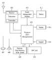
- FIG. 1shows an example of a transmitting apparatus and/or a receiving apparatus of the present specification.
- WLANwireless LAN
- 3is a view for explaining a general link setup process.
- FIG. 4is a diagram illustrating an example of a PPDU used in the IEEE standard.
- 5shows an operation according to UL-MU.
- FIG. 6shows an example of a trigger frame.
- FIG. 7shows an example of a common information field of a trigger frame.
- FIG. 8shows an example of a subfield included in a per user information field.
- FIG. 10shows an example of a PPDU used in this specification.
- FIG. 11shows a modified example of a transmitting apparatus and/or a receiving apparatus of the present specification.
- FIG. 13shows an example of a Multi-Link Traffic element format.
- FIG. 15shows an example of a TIM bitmap and an LMB element.
- 16shows an example of indicating traffic for TIDs mapped to all links by setting all bits of the Link Bitmap to 1.
- FIG. 17shows an example of indicating traffic for TIDs mapped to all links by setting all bits of the Link Bitmap to 0.
- FIG. 18shows an example of an LMB element further including a Link bitmap present field.
- FIG. 19shows an example of an LMB element further including a Link bitmap length field.
- 21shows an example of adding one more bit to the Link Bitmap indicated in the Link Bitmap Present field.
- FIG. 22is a flowchart illustrating a procedure in which a transmitting MLD transmits traffic information for a TID mapped to all links or a specific link according to the present embodiment.
- FIG. 23is a flowchart illustrating a procedure in which a receiving MLD receives traffic information for a TID mapped to all links or a specific link according to the present embodiment.
- a or B (A or B)may mean “only A”, “only B” or “both A and B”.
- a or B (A or B)”may be interpreted as “A and/or B (A and/or B)”.
- A, B or C (A, B or C)” hereinmeans “only A,” “only B,” “only C,” or “any and any combination of A, B and C. combination of A, B and C)”.
- a slash (/) or a comma (comma) used hereinmay mean “and/or”.
- A/Bmay mean “and/or B”.
- A/Bmay mean “only A”, “only B”, or “both A and B”.
- A, B, Cmay mean “A, B, or C”.
- At least one of A and Bmay mean “only A”, “only B” or “both A and B”.
- the expression “at least one of A or B” or “at least one of A and/or B”means “at least one It can be interpreted the same as “at least one of A and B”.
- At least one of A, B and Cmeans “only A”, “only B”, “only C” or “of A, B and C”. any combination of A, B and C”. Also, “at least one of A, B or C” or “at least one of A, B and/or C” means may mean “at least one of A, B and C”.
- control informationEHT-Signal
- EHT-Signalwhen displayed as “control information (EHT-Signal)”, “EHT-Signal” may be proposed as an example of “control information”.
- control informationof the present specification is not limited to “EHT-Signal”, and “EHT-Signal” may be proposed as an example of “control information”.
- control informationie, EHT-signal
- EHT-Signaleven when displayed as “control information (ie, EHT-signal)”, “EHT-Signal” may be proposed as an example of “control information”.
- the following examples of the present specificationmay be applied to various wireless communication systems.
- the following example of the present specificationmay be applied to a wireless local area network (WLAN) system.
- the present specificationmay be applied to the IEEE 802.11a/g/n/ac standard or the IEEE 802.11ax standard.
- this specificationmay be applied to the newly proposed EHT standard or IEEE 802.11be standard.
- an example of the present specificationmay be applied to the EHT standard or a new wireless LAN standard that is an enhancement of IEEE 802.11be.
- an example of the present specificationmay be applied to a mobile communication system.
- LTELong Term Evolution
- 3GPP3rd Generation Partnership Project
- an example of the present specificationmay be applied to a communication system of the 5G NR standard based on the 3GPP standard.
- FIG. 1shows an example of a transmitting apparatus and/or a receiving apparatus of the present specification.
- the example of FIG. 1may perform various technical features described below.
- 1relates to at least one STA (station).
- the STAs 110 and 120 of the present specificationare a mobile terminal, a wireless device, a wireless transmit/receive unit (WTRU), a user equipment (UE), It may also be called by various names such as a mobile station (MS), a mobile subscriber unit, or simply a user.
- the STAs 110 and 120 in the present specificationmay be referred to by various names such as a network, a base station, a Node-B, an access point (AP), a repeater, a router, and a relay.
- the STAs 110 and 120may be referred to by various names such as a receiving device, a transmitting device, a receiving STA, a transmitting STA, a receiving device, and a transmitting device.
- the STAs 110 and 120may perform an access point (AP) role or a non-AP role. That is, the STAs 110 and 120 of the present specification may perform AP and/or non-AP functions.
- the APmay also be indicated as an AP STA.
- the STAs 110 and 120 of the present specificationmay support various communication standards other than the IEEE 802.11 standard.
- a communication standardeg, LTE, LTE-A, 5G NR standard
- the STA of the present specificationmay be implemented in various devices such as a mobile phone, a vehicle, and a personal computer.
- the STA of the present specificationmay support communication for various communication services such as voice call, video call, data communication, and autonomous driving (Self-Driving, Autonomous-Driving).
- the STAs 110 and 120may include a medium access control (MAC) conforming to the IEEE 802.11 standard and a physical layer interface for a wireless medium.
- MACmedium access control
- the STAs 110 and 120will be described based on the sub-view (a) of FIG. 1 as follows.
- the first STA 110may include a processor 111 , a memory 112 , and a transceiver 113 .
- the illustrated processor, memory, and transceivermay each be implemented as separate chips, or at least two or more blocks/functions may be implemented through one chip.
- the transceiver 113 of the first STAperforms a signal transmission/reception operation. Specifically, IEEE 802.11 packets (eg, IEEE 802.11a/b/g/n/ac/ax/be, etc.) may be transmitted/received.
- IEEE 802.11 packetseg, IEEE 802.11a/b/g/n/ac/ax/be, etc.
- the first STA 110may perform an intended operation of the AP.
- the processor 111 of the APmay receive a signal through the transceiver 113 , process the received signal, generate a transmission signal, and perform control for signal transmission.
- the memory 112 of the APmay store a signal (ie, a received signal) received through the transceiver 113 , and may store a signal to be transmitted through the transceiver (ie, a transmission signal).
- the second STA 120may perform an intended operation of a non-AP STA.
- the transceiver 123 of the non-APperforms a signal transmission/reception operation.
- IEEE 802.11 packetseg, IEEE 802.11a/b/g/n/ac/ax/be, etc.
- IEEE 802.11a/b/g/n/ac/ax/be, etc.may be transmitted/received.
- the processor 121 of the non-AP STAmay receive a signal through the transceiver 123 , process the received signal, generate a transmission signal, and perform control for signal transmission.
- the memory 122 of the non-AP STAmay store a signal (ie, a received signal) received through the transceiver 123 and may store a signal to be transmitted through the transceiver (ie, a transmission signal).
- an operation of a device indicated as an AP in the following specificationmay be performed by the first STA 110 or the second STA 120 .
- the operation of the device marked as APis controlled by the processor 111 of the first STA 110 , and is controlled by the processor 111 of the first STA 110 .
- Relevant signalsmay be transmitted or received via the controlled transceiver 113 .
- control information related to an operation of the AP or a transmission/reception signal of the APmay be stored in the memory 112 of the first STA 110 .
- the operation of the device indicated by the APis controlled by the processor 121 of the second STA 120 and controlled by the processor 121 of the second STA 120 .
- a related signalmay be transmitted or received via the transceiver 123 that is used.
- control information related to an operation of the AP or a transmission/reception signal of the APmay be stored in the memory 122 of the second STA 110 .
- an operation of a device indicated as a non-APin the following specification may be performed by the first STA 110 or the second STA 120 .
- the operation of the device marked as non-APis controlled by the processor 121 of the second STA 120, and the processor ( A related signal may be transmitted or received via the transceiver 123 controlled by 121 .
- control information related to the operation of the non-AP or the AP transmit/receive signalmay be stored in the memory 122 of the second STA 120 .
- the operation of the device marked as non-APis controlled by the processor 111 of the first STA 110 , and the processor ( Related signals may be transmitted or received via transceiver 113 controlled by 111 .
- control information related to the operation of the non-AP or the AP transmission/reception signalmay be stored in the memory 112 of the first STA 110 .
- transmission / receptionSTA, first STA, second STA, STA1, STA2, AP, first AP, second AP, AP1, AP2, (transmission / reception) Terminal, (transmission / reception) device , (transmitting/receiving) apparatus, a device called a network, etc. may refer to the STAs 110 and 120 of FIG. 1 .
- a device indicated by a /receiver) device, a (transmit/receive) apparatus, and a networkmay also refer to the STAs 110 and 120 of FIG. 1 .
- an operation in which various STAs transmit and receive signalsmay be performed by the transceivers 113 and 123 of FIG. 1 .
- an example of an operation of generating a transmission/reception signal or performing data processing or operation in advance for a transmission/reception signalis 1) Determining bit information of a subfield (SIG, STF, LTF, Data) field included in a PPDU /Acquisition/configuration/computation/decoding/encoding operation, 2) time resource or frequency resource (eg, subcarrier resource) used for the subfield (SIG, STF, LTF, Data) field included in the PPDU, etc.
- a specific sequenceeg, pilot sequence, STF / LTF sequence, SIG
- SIGsubfield
- SIGsubfield
- STFsubfield
- LTFLTF
- Datasubfield
- an operation related to determination / acquisition / configuration / operation / decoding / encoding of an ACK signalmay include
- various informationeg, field/subfield/control field/parameter/power related information used by various STAs for determination/acquisition/configuration/computation/decoding/encoding of transmit/receive signals is may be stored in the memories 112 and 122 of FIG. 1 .
- the device/STA of the sub-view (a) of FIG. 1 described abovemay be modified as shown in the sub-view (b) of FIG. 1 .
- the STAs 110 and 120 of the present specificationwill be described based on the sub-drawing (b) of FIG. 1 .
- the transceivers 113 and 123 illustrated in (b) of FIG. 1may perform the same function as the transceivers illustrated in (a) of FIG. 1 .
- the processing chips 114 and 124 illustrated in (b) of FIG. 1may include processors 111 and 121 and memories 112 and 122 .
- the processors 111 and 121 and the memories 112 and 122 illustrated in (b) of FIG. 1are the processors 111 and 121 and the memories 112 and 122 illustrated in (a) of FIG. ) can perform the same function.
- a technical feature in which a transmitting STA transmits a control signalis that the control signals generated by the processors 111 and 121 shown in the sub-drawings (a)/(b) of FIG. 1 are (a) of FIG. ) / (b) can be understood as a technical feature transmitted through the transceivers 113 and 123 shown in (b).
- the technical feature in which the transmitting STA transmits the control signalis a technical feature in which a control signal to be transmitted to the transceivers 113 and 123 is generated from the processing chips 114 and 124 shown in the sub-view (b) of FIG. can be understood
- the technical feature in which the receiving STA receives the control signalmay be understood as the technical feature in which the control signal is received by the transceivers 113 and 123 shown in the sub-drawing (a) of FIG. 1 .
- the technical feature that the receiving STA receives the control signalis that the control signal received by the transceivers 113 and 123 shown in the sub-drawing (a) of FIG. 1 is the processor shown in (a) of FIG. 111, 121) can be understood as a technical feature obtained by.
- the technical feature for the receiving STA to receive the control signalis that the control signal received by the transceivers 113 and 123 shown in the sub-view (b) of FIG. 1 is the processing chip shown in the sub-view (b) of FIG. It can be understood as a technical feature obtained by (114, 124).
- software codes 115 and 125may be included in the memories 112 and 122 .
- the software codes 115 and 125may include instructions for controlling the operations of the processors 111 and 121 .
- Software code 115, 125may be included in a variety of programming languages.
- the processors 111 and 121 or the processing chips 114 and 124 shown in FIG. 1may include an application-specific integrated circuit (ASIC), other chipsets, logic circuits, and/or data processing devices.
- the processormay be an application processor (AP).
- the processors 111 and 121 or the processing chips 114 and 124 illustrated in FIG. 1may include a digital signal processor (DSP), a central processing unit (CPU), a graphics processing unit (GPU), and a modem (Modem). and demodulator).
- DSPdigital signal processor
- CPUcentral processing unit
- GPUgraphics processing unit
- Modemmodem
- demodulatordemodulator
- SNAPDRAGONTM series processormanufactured by Qualcomm®, an EXYNOSTM series processor manufactured by Samsung®, and a processor manufactured by Apple®. It may be an A series processor, a HELIOTM series processor manufactured by MediaTek®, an ATOMTM series processor manufactured by INTEL®, or a processor enhanced therewith.
- uplinkmay mean a link for communication from a non-AP STA to an AP STA, and an uplink PPDU/packet/signal may be transmitted through the uplink.
- downlinkmay mean a link for communication from an AP STA to a non-AP STA, and a downlink PPDU/packet/signal may be transmitted through the downlink.
- WLANwireless LAN
- FIG. 2shows the structure of an infrastructure basic service set (BSS) of the Institute of Electrical and Electronic Engineers (IEEE) 802.11.
- BSSinfrastructure basic service set
- IEEEInstitute of Electrical and Electronic Engineers
- a wireless LAN systemmay include one or more infrastructure BSSs 200 and 205 (hereinafter, BSSs).
- BSSs 200 and 205are a set of APs and STAs such as an access point (AP) 225 and a station 200-1 (STA1) that can communicate with each other through successful synchronization, and are not a concept indicating a specific area.
- the BSS 205may include one or more combinable STAs 205 - 1 and 205 - 2 to one AP 230 .
- the BSSmay include at least one STA, the APs 225 and 230 providing a distribution service, and a distribution system (DS) 210 connecting a plurality of APs.
- DSdistribution system
- the distributed system 210may implement an extended service set (ESS) 240 that is an extended service set by connecting several BSSs 200 and 205 .
- ESS 240may be used as a term indicating one network in which one or several APs are connected through the distributed system 210 .
- APs included in one ESS 240may have the same service set identification (SSID).
- the portal 220may serve as a bridge connecting a wireless LAN network (IEEE 802.11) and another network (eg, 802.X).
- IEEE 802.11IEEE 802.11
- 802.Xanother network
- a network between the APs 225 and 230 and a network between the APs 225 and 230 and the STAs 200 - 1 , 205 - 1 and 205 - 2may be implemented.
- a network that establishes a network and performs communication even between STAs without the APs 225 and 230is defined as an ad-hoc network or an independent basic service set (IBSS).
- FIG. 2The lower part of FIG. 2 is a conceptual diagram illustrating the IBSS.
- the IBSSis a BSS operating in an ad-hoc mode. Since IBSS does not include an AP, there is no centralized management entity that performs a centralized management function. That is, in the IBSS, the STAs 250-1, 250-2, 250-3, 255-4, and 255-5 are managed in a distributed manner. In IBSS, all STAs (250-1, 250-2, 250-3, 255-4, 255-5) can be mobile STAs, and access to a distributed system is not allowed, so a self-contained network network) is formed.
- 3is a view for explaining a general link setup process.
- the STAmay perform a network discovery operation.
- the network discovery operationmay include a scanning operation of the STA. That is, in order for the STA to access the network, it is necessary to find a network in which it can participate.
- An STAmust identify a compatible network before participating in a wireless network.
- the process of identifying a network existing in a specific areais called scanning. Scanning methods include active scanning and passive scanning.
- an STA performing scanningtransmits a probe request frame to discover which APs exist nearby while moving channels, and waits for a response.
- a respondertransmits a probe response frame to the STA that has transmitted the probe request frame in response to the probe request frame.
- the respondermay be an STA that last transmitted a beacon frame in the BSS of the channel being scanned.
- the APsince the AP transmits a beacon frame, the AP becomes the responder.
- the STAs in the IBSSrotate and transmit the beacon frame, so the responder is not constant.
- an STA that transmits a probe request frame on channel 1 and receives a probe response frame on channel 1stores BSS-related information included in the received probe response frame and channel) to perform scanning (ie, probe request/response transmission/reception on channel 2) in the same way.
- the scanning operationmay be performed in a passive scanning manner.
- An STA performing scanning based on passive scanningmay wait for a beacon frame while moving channels.
- the beacon frameis one of the management frames in IEEE 802.11, and is periodically transmitted to inform the existence of a wireless network, and to allow a scanning STA to search for a wireless network and participate in the wireless network.
- the APplays a role of periodically transmitting a beacon frame, and in the IBSS, the STAs in the IBSS rotate and transmit the beacon frame.
- the STA performing scanningreceives the beacon frame, it stores information on the BSS included in the beacon frame and records beacon frame information in each channel while moving to another channel.
- the STAmay store BSS-related information included in the received beacon frame, move to the next channel, and perform scanning on the next channel in the same manner.
- the STA discovering the networkmay perform an authentication process through step S320.
- This authentication processmay be referred to as a first authentication process in order to clearly distinguish it from the security setup operation of step S340 to be described later.
- the authentication process of S320may include a process in which the STA transmits an authentication request frame to the AP, and in response thereto, the AP transmits an authentication response frame to the STA.
- An authentication frame used for an authentication request/responsecorresponds to a management frame.
- the authentication frameincludes an authentication algorithm number, an authentication transaction sequence number, a status code, a challenge text, a Robust Security Network (RSN), and a Finite Cyclic Group), etc. may be included.
- RSNRobust Security Network
- Finite Cyclic GroupFinite Cyclic Group
- the STAmay transmit an authentication request frame to the AP.
- the APmay determine whether to allow authentication for the corresponding STA based on information included in the received authentication request frame.
- the APmay provide the result of the authentication process to the STA through the authentication response frame.
- the successfully authenticated STAmay perform a connection process based on step S330.
- the association processincludes a process in which the STA transmits an association request frame to the AP, and in response, the AP transmits an association response frame to the STA.
- the connection request frameincludes information related to various capabilities, a beacon listening interval, a service set identifier (SSID), supported rates, supported channels, RSN, and a mobility domain.
- SSIDservice set identifier
- supported ratessupported channels
- RSNradio station
- TIM broadcast requestTraffic Indication Map Broadcast request
- connection response frameincludes information related to various capabilities, status codes, Association IDs (AIDs), support rates, Enhanced Distributed Channel Access (EDCA) parameter sets, Received Channel Power Indicator (RCPI), Received Signal to Noise (RSNI). indicator), mobility domain, timeout interval (association comeback time), overlapping BSS scan parameters, TIM broadcast response, QoS map, and the like.
- AIDsAssociation IDs
- EDCAEnhanced Distributed Channel Access
- RCPIReceived Channel Power Indicator
- RSNIReceived Signal to Noise
- indicatormobility domain
- timeout intervalassociation comeback time
- overlapping BSS scan parametersTIM broadcast response
- QoS mapQoS map
- step S340the STA may perform a security setup process.
- the security setup process of step S340may include, for example, a process of private key setup through 4-way handshaking through an Extensible Authentication Protocol over LAN (EAPOL) frame. .
- EAPOLExtensible Authentication Protocol over LAN
- FIG. 4is a diagram illustrating an example of a PPDU used in the IEEE standard.
- the LTF and STF fieldsinclude a training signal
- SIG-A and SIG-Binclude control information for the receiving station
- the data fieldincludes user data corresponding to MAC PDU/Aggregated MAC PDU (PSDU).
- the HE PPDU according to FIG. 4is an example of a PPDU for multiple users, and HE-SIG-B may be included only for multiple users, and the corresponding HE-SIG-B may be omitted from the PPDU for a single user.
- HE-PPDU for multiple usersis L-STF (legacy-short training field), L-LTF (legacy-long training field), L-SIG (legacy-signal), HE-SIG-A (high efficiency-signal A), HE-SIG-B (high efficiency-signal-B), HE-STF (high efficiency-short training field), HE-LTF (high efficiency-long training field) , a data field (or MAC payload) and a packet extension (PE) field.
- Each fieldmay be transmitted during the illustrated time interval (ie, 4 or 8 ⁇ s, etc.).
- a resource unitmay include a plurality of subcarriers (or tones).
- the resource unitmay be used when transmitting a signal to a plurality of STAs based on the OFDMA technique. Also, even when a signal is transmitted to one STA, a resource unit may be defined.
- the resource unitmay be used for STF, LTF, data field, and the like.
- the RU described in this specificationmay be used for uplink (UL) communication and downlink (DL) communication.
- a transmitting STAeg, AP
- a first RUeg, 26/52/106
- a second RUeg, 26/52/106/242-RU, etc.
- the first STAmay transmit a first trigger-based PPDU based on the first RU
- the second STAmay transmit a second trigger-based PPDU based on the second RU.
- the first/second trigger-based PPDUsare transmitted to the AP in the same time interval.
- the transmitting STA(eg, AP) allocates a first RU (eg, 26/52/106/242-RU, etc.) to the first STA, and A second RU (eg, 26/52/106/242-RU, etc.) may be allocated to the 2 STAs. That is, the transmitting STA (eg, AP) may transmit the HE-STF, HE-LTF, and Data fields for the first STA through the first RU within one MU PPDU, and the second through the second RU. HE-STF, HE-LTF, and Data fields for 2 STAs may be transmitted.
- the transmitting STAmay perform channel access through contending (ie, backoff operation) and transmit a trigger frame 1030 . That is, the transmitting STA (eg, AP) may transmit the PPDU including the Trigger Frame 1330 .
- a TB (trigger-based) PPDUis transmitted after a delay of SIFS.
- the TB PPDUs 1041 and 1042may be transmitted in the same time zone, and may be transmitted from a plurality of STAs (eg, user STAs) whose AIDs are indicated in the trigger frame 1030 .
- the ACK frame 1050 for the TB PPDUmay be implemented in various forms.
- an orthogonal frequency division multiple access (OFDMA) technique or MU MIMO techniquemay be used, and OFDMA and MU MIMO technique may be used simultaneously.
- OFDMAorthogonal frequency division multiple access
- the trigger frame of FIG. 6allocates resources for uplink multiple-user transmission (MU), and may be transmitted, for example, from an AP.
- the trigger framemay be composed of a MAC frame and may be included in a PPDU.
- Each field shown in FIG. 6may be partially omitted, and another field may be added. In addition, the length of each field may be changed differently from that shown.
- the frame control field 1110 of FIG. 6includes information about the version of the MAC protocol and other additional control information, and the duration field 1120 includes time information for NAV setting or an STA identifier (eg, For example, information on AID) may be included.
- the RA field 1130includes address information of the receiving STA of the corresponding trigger frame, and may be omitted if necessary.
- the TA field 1140includes address information of an STA (eg, AP) that transmits the trigger frame
- the common information field 1150is a common information field 1150 applied to the receiving STA that receives the trigger frame.
- a field indicating the length of the L-SIG field of the uplink PPDU transmitted in response to the trigger frame or the SIG-A field (ie, HE-SIG-A) in the uplink PPDU transmitted in response to the trigger frame. field)may include information controlling the content.
- common control informationinformation on the length of the CP or the length of the LTF field of the uplink PPDU transmitted in response to the trigger frame may be included.
- per user information fields 1160#1 to 1160#Ncorresponding to the number of receiving STAs receiving the trigger frame of FIG. 6 .
- the individual user information fieldmay be referred to as an “allocation field”.
- the trigger frame of FIG. 6may include a padding field 1170 and a frame check sequence field 1180 .
- Each of the per user information fields 1160#1 to 1160#N shown in FIG. 6may again include a plurality of subfields.
- FIG. 7shows an example of a common information field of a trigger frame. Some of the subfields of FIG. 7 may be omitted, and other subfields may be added. Also, the length of each subfield shown may be changed.
- the illustrated length field 1210has the same value as the length field of the L-SIG field of the uplink PPDU transmitted in response to the trigger frame, and the length field of the L-SIG field of the uplink PPDU indicates the length of the uplink PPDU.
- the length field 1210 of the trigger framemay be used to indicate the length of the corresponding uplink PPDU.
- the cascade indicator field 1220indicates whether a cascade operation is performed.
- the cascade operationmeans that downlink MU transmission and uplink MU transmission are performed together in the same TXOP. That is, after downlink MU transmission is performed, it means that uplink MU transmission is performed after a preset time (eg, SIFS).
- a preset timeeg, SIFS.
- the CS request field 1230indicates whether the state of the radio medium or NAV should be considered in a situation in which the receiving device receiving the corresponding trigger frame transmits the corresponding uplink PPDU.
- the HE-SIG-A information field 1240may include information for controlling the content of the SIG-A field (ie, the HE-SIG-A field) of the uplink PPDU transmitted in response to the corresponding trigger frame.
- the CP and LTF type field 1250may include information on the LTF length and CP length of the uplink PPDU transmitted in response to the corresponding trigger frame.
- the trigger type field 1060may indicate the purpose for which the corresponding trigger frame is used, for example, normal triggering, triggering for beamforming, and a request for Block ACK/NACK.
- the trigger type field 1260 of the trigger frameindicates a basic type trigger frame for normal triggering.
- a basic type trigger framemay be referred to as a basic trigger frame.
- the user information field 1300 of FIG. 8may be understood as any one of the individual user information fields 1160#1 to 1160#N mentioned in FIG. 6 above. Some of the subfields included in the user information field 1300 of FIG. 8 may be omitted, and other subfields may be added. Also, the length of each subfield shown may be changed.
- a User Identifier field 1310 of FIG. 8indicates an identifier of an STA (ie, a receiving STA) corresponding to per user information, and an example of the identifier is an association identifier (AID) of the receiving STA. It can be all or part of a value.
- an RU Allocation field 1320may be included. That is, when the receiving STA identified by the user identifier field 1310 transmits the TB PPDU in response to the trigger frame, it transmits the TB PPDU through the RU indicated by the RU allocation field 1320 .
- the subfield of FIG. 8may include a coding type field 1330 .
- the coding type field 1330may indicate the coding type of the TB PPDU. For example, when BCC coding is applied to the TB PPDU, the coding type field 1330 is set to '1', and when LDPC coding is applied, the coding type field 1330 can be set to '0'. have.
- the subfield of FIG. 8may include an MCS field 1340 .
- the MCS field 1340may indicate an MCS technique applied to a TB PPDU. For example, when BCC coding is applied to the TB PPDU, the coding type field 1330 is set to '1', and when LDPC coding is applied, the coding type field 1330 can be set to '0'. have.
- the transmitting STAmay allocate 6 RU resources as shown in FIG. 9 through a trigger frame.
- the APis a first RU resource (AID 0, RU 1), a second RU resource (AID 0, RU 2), a third RU resource (AID 0, RU 3), a fourth RU resource (AID 2045, RU) 4), a fifth RU resource (AID 2045, RU 5) and a sixth RU resource (AID 3, RU 6) may be allocated.
- Information on AID 0, AID 3, or AID 2045may be included, for example, in the user identification field 1310 of FIG. 8 .
- Information on RU 1 to RU 6may be included in, for example, the RU allocation field 1320 of FIG. 8 .
- the first to third RU resources of FIG. 9may be used as UORA resources for an associated STA
- the fourth to fifth RU resources of FIG. 9are non-associated for STAs. It may be used as a UORA resource
- the sixth RU resource of FIG. 9may be used as a resource for a normal UL MU.
- the OFDMA random access BackOff (OBO) counter of STA1decreases to 0, and STA1 randomly selects the second RU resources (AID 0, RU 2).
- OBO counter of STA2/3is greater than 0, uplink resources are not allocated to STA2/3.
- STA1 of FIG. 9is an associated STA, there are a total of three eligible RA RUs for STA1 (RU 1, RU 2, RU 3), and accordingly, STA1 decrements the OBO counter by 3 to increase the OBO counter. became 0.
- STA2 of FIG. 9is an associated STA, a total of three eligible RA RUs for STA2 (RU 1, RU 2, RU 3), and accordingly, STA2 decrements the OBO counter by 3, but the OBO counter is 0 is in a larger state.
- STA3 of FIG. 9is an un-associated STA, the eligible RA RUs for STA3 are two (RU 4, RU 5) in total, and accordingly, STA3 decrements the OBO counter by 2, but the OBO counter is is greater than 0.
- FIG. 10shows an example of a PPDU used in this specification.
- the PPDU of FIG. 10may be called by various names such as an EHT PPDU, a transmission PPDU, a reception PPDU, a first type or an Nth type PPDU.
- a PPDU or an EHT PPDUmay be referred to by various names such as a transmission PPDU, a reception PPDU, a first type or an Nth type PPDU.
- the EHT PPUmay be used in an EHT system and/or a new wireless LAN system in which the EHT system is improved.
- the PPDU of FIG. 10may represent some or all of the PPDU types used in the EHT system.
- the example of FIG. 10may be used for both a single-user (SU) mode and a multi-user (MU) mode.
- the PPDU of FIG. 10may be a PPDU for one receiving STA or a plurality of receiving STAs.
- the EHT-SIG of FIG. 10may be omitted.
- the STA that has received the trigger frame for uplink-MU (UL-MU) communicationmay transmit a PPDU in which the EHT-SIG is omitted in the example of FIG. 10 .
- L-STF to EHT-LTFmay be referred to as a preamble or a physical preamble, and may be generated/transmitted/received/acquired/decoded in a physical layer.
- the subcarrier spacing of the L-STF, L-LTF, L-SIG, RL-SIG, U-SIG, and EHT-SIG fields of FIG. 10is set to 312.5 kHz, and the subcarrier spacing of the EHT-STF, EHT-LTF, and Data fields may be set to 78.125 kHz. That is, the tone index (or subcarrier index) of the L-STF, L-LTF, L-SIG, RL-SIG, U-SIG, and EHT-SIG fields is displayed in units of 312.5 kHz, EHT-STF, EHT-LTF, The tone index (or subcarrier index) of the Data field may be displayed in units of 78.125 kHz.
- L-LTF and L-STFmay be the same as the conventional fields.
- the L-SIG field of FIG. 10may include, for example, 24-bit bit information.
- 24-bit informationmay include a 4-bit Rate field, a 1-bit Reserved bit, a 12-bit Length field, a 1-bit Parity bit, and a 6-bit Tail bit.
- the 12-bit Length fieldmay include information about the length or time duration of the PPDU.
- the value of the 12-bit Length fieldmay be determined based on the type of the PPDU. For example, when the PPDU is a non-HT, HT, VHT PPDU or an EHT PPDU, the value of the Length field may be determined as a multiple of 3.
- the value of the Length fieldmay be determined as “a multiple of 3 + 1” or “a multiple of 3 +2”.
- the value of the Length fieldmay be determined as a multiple of 3
- the value of the Length fieldis “a multiple of 3 + 1” or “a multiple of 3” +2”.
- the transmitting STAmay apply BCC encoding based on a code rate of 1/2 to 24-bit information of the L-SIG field. Thereafter, the transmitting STA may acquire a 48-bit BCC encoding bit. BPSK modulation may be applied to 48-bit coded bits to generate 48 BPSK symbols. The transmitting STA may map 48 BPSK symbols to positions excluding pilot subcarriers ⁇ subcarrier indexes -21, -7, +7, +21 ⁇ and DC subcarriers ⁇ subcarrier index 0 ⁇ .
- the transmitting STAmay additionally map signals of ⁇ -1, -1, -1, 1 ⁇ to the subcarrier indexes ⁇ -28, -27, +27, 28 ⁇ .
- the above signalcan be used for channel estimation in the frequency domain corresponding to ⁇ -28, -27, +27, 28 ⁇ .
- the transmitting STAmay generate the RL-SIG generated in the same way as the L-SIG.
- BPSK modulationis applied.
- the receiving STAmay know that the received PPDU is an HE PPDU or an EHT PPDU based on the existence of the RL-SIG.
- a U-SIGmay be inserted after the RL-SIG of FIG. 10 .
- the U-SIGmay be referred to by various names, such as a first SIG field, a first SIG, a first type SIG, a control signal, a control signal field, and a first (type) control signal.
- the U-SIGmay include information of N bits, and may include information for identifying the type of the EHT PPDU.
- the U-SIGmay be configured based on two symbols (eg, two consecutive OFDM symbols).
- Each symbol (eg, OFDM symbol) for U-SIGmay have a duration of 4 us.
- Each symbol of the U-SIGmay be used to transmit 26-bit information.
- each symbol of U-SIGmay be transmitted/received based on 52 data tones and 4 pilot tones.
- A-bit information(eg, 52 un-coded bits) may be transmitted, and the first symbol of the U-SIG is the first of the total A-bit information.
- X-bit information(eg, 26 un-coded bits) is transmitted, and the second symbol of U-SIG can transmit the remaining Y-bit information (eg, 26 un-coded bits) of the total A-bit information.
- the transmitting STAmay obtain 26 un-coded bits included in each U-SIG symbol.
- the transmitting STAmay generate 52 BPSK symbols allocated to each U-SIG symbol by performing BPSK modulation on the interleaved 52-coded bits.
- One U-SIG symbolmay be transmitted based on 56 tones (subcarriers) from subcarrier index -28 to subcarrier index +28, except for DC index 0.
- the 52 BPSK symbols generated by the transmitting STAmay be transmitted based on the remaining tones (subcarriers) excluding pilot tones -21, -7, +7, and +21 tones.
- A-bit information (eg, 52 un-coded bits) transmitted by U-SIGincludes a CRC field (eg, a 4-bit long field) and a tail field (eg, a 6-bit long field). ) may be included.
- the CRC field and the tail fieldmay be transmitted through the second symbol of the U-SIG.
- the CRC fieldmay be generated based on the remaining 16 bits except for the CRC/tail field in the 26 bits allocated to the first symbol of the U-SIG and the second symbol, and may be generated based on the conventional CRC calculation algorithm.
- the tail fieldmay be used to terminate the trellis of the convolutional decoder, and may be set, for example, to “000000”.
- a bit information (eg, 52 un-coded bits) transmitted by U-SIGmay be divided into version-independent bits and version-dependent bits.
- the size of version-independent bitsmay be fixed or variable.
- the version-independent bitsmay be allocated only to the first symbol of the U-SIG, or the version-independent bits may be allocated to both the first symbol and the second symbol of the U-SIG.
- the version-independent bits and the version-dependent bitsmay be referred to by various names such as a first control bit and a second control bit.
- the version-independent bits of the U-SIGmay include a 3-bit PHY version identifier.
- the 3-bit PHY version identifiermay include information related to the PHY version of the transmission/reception PPDU.
- the first value of the 3-bit PHY version identifiermay indicate that the transmission/reception PPDU is an EHT PPDU.
- the transmitting STAmay set the 3-bit PHY version identifier to the first value.
- the receiving STAmay determine that the receiving PPDU is an EHT PPDU based on the PHY version identifier having the first value.
- the version-independent bits of the U-SIGmay include a 1-bit UL/DL flag field.
- a first value of the 1-bit UL/DL flag fieldrelates to UL communication, and a second value of the UL/DL flag field relates to DL communication.
- the version-independent bits of the U-SIGmay include information about the length of the TXOP and information about the BSS color ID.
- EHT PPDUwhen the EHT PPDU is divided into various types (eg, various types such as EHT PPDU related to SU mode, EHT PPDU related to MU mode, EHT PPDU related to TB mode, EHT PPDU related to Extended Range transmission) , information on the type of the EHT PPDU may be included in the version-dependent bits of the U-SIG.
- various typeseg, various types such as EHT PPDU related to SU mode, EHT PPDU related to MU mode, EHT PPDU related to TB mode, EHT PPDU related to Extended Range transmission
- information on the type of the EHT PPDUmay be included in the version-dependent bits of the U-SIG.
- U-SIGis 1) a bandwidth field including information about bandwidth, 2) a field including information about an MCS technique applied to EHT-SIG, 3) dual subcarrier modulation to EHT-SIG (dual An indication field including information on whether subcarrier modulation, DCM) technique is applied, 4) a field including information on the number of symbols used for EHT-SIG, 5) EHT-SIG is generated over the entire band It may include information about a field including information on whether or not, 6) a field including information about the type of EHT-LTF/STF, 7) a field indicating the length of EHT-LTF and a CP length.
- (transmit/receive/uplink/downlink) signalsmay be a signal transmitted/received based on the PPDU of FIG. 10 .
- the PPDU of FIG. 10may be used to transmit and receive various types of frames.
- the PPDU of FIG. 10may be used for a control frame.
- control framemay include request to send (RTS), clear to send (CTS), Power Save-Poll (PS-Poll), BlockACKReq, BlockAck, Null Data Packet (NDP) announcement, and Trigger Frame.
- the PPDU of FIG. 18may be used for a management frame.
- An example of the management framemay include a Beacon frame, (Re-)Association Request frame, (Re-)Association Response frame, Probe Request frame, and Probe Response frame.
- the PPDU of FIG. 10may be used for a data frame.
- the PPDU of FIG. 10may be used to simultaneously transmit at least two or more of a control frame, a management frame, and a data frame.
- FIG. 11shows a modified example of a transmitting apparatus and/or a receiving apparatus of the present specification.
- Each device/STA of the sub-drawings (a)/(b) of FIG. 1may be modified as shown in FIG. 11 .
- the transceiver 630 of FIG. 11may be the same as the transceivers 113 and 123 of FIG. 1 .
- the transceiver 630 of FIG. 11may include a receiver and a transmitter.
- the processor 610 of FIG. 11may be the same as the processors 111 and 121 of FIG. 1 . Alternatively, the processor 610 of FIG. 11 may be the same as the processing chips 114 and 124 of FIG. 1 .
- the memory 150 of FIG. 11may be the same as the memories 112 and 122 of FIG. 1 .
- the memory 150 of FIG. 11may be a separate external memory different from the memories 112 and 122 of FIG. 1 .
- the power management module 611manages power for the processor 610 and/or the transceiver 630 .
- the battery 612supplies power to the power management module 611 .
- the display 613outputs the result processed by the processor 610 .
- Keypad 614receives input to be used by processor 610 .
- a keypad 614may be displayed on the display 613 .
- SIM card 615may be an integrated circuit used to securely store an international mobile subscriber identity (IMSI) used to identify and authenticate subscribers in mobile phone devices, such as mobile phones and computers, and keys associated therewith. .
- IMSIinternational mobile subscriber identity
- the speaker 640may output a sound related result processed by the processor 610 .
- the microphone 641may receive a sound related input to be used by the processor 610 .
- the STA (AP and/or non-AP STA) of the present specificationmay support multi-link (ML) communication.
- ML communicationmay refer to communication supporting a plurality of links.
- Links related to ML communicationmay include channels of a 2.4 GHz band, a 5 GHz band, and a 6 GHz band (eg, 20/40/80/160/240/320 MHz channels).
- a plurality of links used for ML communicationmay be set in various ways.
- a plurality of links supported by one STA for ML communicationmay be a plurality of channels in a 2.4 GHz band, a plurality of channels in a 5 GHz band, and a plurality of channels in a 6 GHz band.
- a plurality of links supported by one STA for ML communicationinclude at least one channel in the 2.4 GHz band (or 5 GHz/6 GHz band) and at least one channel in the 5 GHz band (or 2.4 GHz/6 GHz band) within It may be a combination of one channel.
- at least one of a plurality of links supported by one STA for ML communicationmay be a channel to which preamble puncturing is applied.
- the STAmay perform ML setup to perform ML communication.
- ML setupmay be performed based on management frames or control frames such as Beacon, Probe Request/Response, Association Request/Response.
- management frames or control framessuch as Beacon, Probe Request/Response, Association Request/Response.
- information about ML configurationmay be included in an element field included in Beacon, Probe Request/Response, and Association Request/Response.
- an enabled link for ML communicationmay be determined.
- the STAmay perform frame exchange through at least one of a plurality of links determined as an enabled link.
- the enabled linkmay be used for at least one of a management frame, a control frame, and a data frame.
- a transceiver supporting each linkmay operate as one logical STA.
- one STA supporting two linksmay be expressed as one multi-link device (MLD) including a first STA for a first link and a second STA for a second link.
- MLDmulti-link device
- one AP supporting two linksmay be expressed as one AP MLD including a first AP for a first link and a second AP for a second link.
- one non-AP supporting two linksmay be expressed as one non-AP MLD including a first STA for the first link and a second STA for the second link.
- the MLDmay transmit information about a link that the corresponding MLD can support through ML setup.
- Link informationmay be configured in various ways.
- information about the linkincludes 1) information on whether the MLD (or STA) supports simultaneous RX/TX operation, 2) the number/upper limit of uplink/downlink links supported by the MLD (or STA) information, 3) information about the location/band/resource of the uplink/downlink link supported by the MLD (or STA), 4) the type of frame available or preferred in at least one uplink/downlink link (management, control, data etc.) information, 5) available or preferred ACK policy information in at least one uplink/downlink link, and 6) available or preferred TID (traffic identifier) information in at least one uplink/downlink link.
- the TIDis related to the priority of traffic data and is expressed as eight types of values according to the conventional wireless LAN standard. That is, eight TID values corresponding to four access categories (AC) (AC_BK (background), AC_BE (best effort), AC_VI (video), and AC_VO (voice)) according to the conventional WLAN standard will be defined.
- ACaccess categories
- AC_BKbackground
- AC_BEbest effort
- AC_VIvideo
- AC_VOvoice
- all TIDs for uplink/downlink linkmay be pre-configured to be mapped. Specifically, if negotiation is not made through ML setup, all TIDs are used for ML communication. can be used for
- a plurality of links usable by the transmitting MLD and the receiving MLD related to ML communicationmay be set, and this may be referred to as an “enabled link”.
- “enabled link”may be called differently in various expressions. For example, it may be referred to as various expressions such as a first link, a second link, a transmission link, and a reception link.
- the MLDmay update the ML setup. For example, the MLD may transmit information about a new link when it is necessary to update information about the link. Information on the new link may be transmitted based on at least one of a management frame, a control frame, and a data frame.
- the device described belowmay be the apparatus of FIGS. 1 and/or 11 , and the PPDU may be the PPDU of FIG. 10 .
- a devicemay be an AP or a non-AP STA.
- the device described belowmay be an AP multi-link device (MLD) supporting multi-link or a non-AP STA MLD.
- MLDAP multi-link device
- EHTextremely high throughput
- the devicemay use one or more bands (eg, 2.4 GHz, 5 GHz, 6 GHz, 60 GHz, etc.) simultaneously or alternately.
- MLDrefers to a multi-link device.
- the MLDhas one or more connected STAs and has one MAC service access point (SAP) that goes to an upper link layer (Logical Link Control, LLC).
- SAPMAC service access point
- LLCLogical Link Control
- MLDmay mean a physical device or a logical device.
- a devicemay mean an MLD.
- a transmitting device and a receiving devicemay refer to MLD.
- the first link of the receiving/transmitting devicemay be a terminal (eg, STA or AP) that performs signal transmission/reception through the first link included in the receiving/transmitting device.
- the second link of the receiving/transmitting devicemay be a terminal (eg, STA or AP) that performs signal transmission/reception through the second link included in the receiving/transmitting device.
- IEEE802.11becan support two types of multi-link operations. For example, simultaneous transmit and receive (STR) and non-STR operations may be considered.
- STRsimultaneous transmit and receive
- non-STRmay be considered.
- an STRmay be referred to as an asynchronous multi-link operation
- a non-STRmay be referred to as a synchronous multi-link operation.
- a multi-linkmay include a multi-band. That is, the multi-link may mean a link included in several frequency bands, or may mean a plurality of links included in one frequency band.
- EHTconsiders multi-link technology, where multi-link may include multi-band. That is, the multi-link can represent links of several bands and can represent multiple multi-links within one band at the same time. Two types of multi-link operation are being considered. Asynchronous operation that enables simultaneous TX/RX on multiple links and synchronous operation that is not possible are considered.
- STRsimultaneous transmit and receive
- STR MLDmulti-link device
- -STR MLDnon-STR MLD
- a TID-To-Link Mapping elementindicates a link capable of exchanging frames belonging to each TID.
- the Direction subfield of the TID-To-Link Control fieldis set to 0 (Downlink).
- the Direction subfieldis set to 1 (Uplink).
- the TID-To-Link Mapping elementprovides TID-to-link mapping information for a frame transmitted in both downlink and uplink.
- the Direction subfieldis set to 2 (bidirectional link). The value 3 is reserved.
- the Default Link Mapping subfield of the TID-To-Link Control fieldis set to 1. Unless the TID-To-Link mapping element indicates a default TID-To-Link mapping, the Default Link Mapping subfield is set to 0.
- the Link Mapping Presence Indicator subfieldindicates whether the Link Mapping Of TID n field exists in the TID-To-Link mapping element. A value of 1 in bit position n of the Link Mapping Presence Indicator subfield indicates that the Link Mapping Of TID n field is present in the TID-To-Link mapping element. Otherwise (if the value is 0 at bit position n of the Link Mapping Presence Indicator subfield), the Link Mapping Of TID n field is not in the TID-To-Link mapping element. If the Default Link Mapping subfield is set to 1, this subfield is reserved.
- a value of 1 in bit position i of the Link Mapping Of TID n fieldindicates that TID n is mapped to the link associated with the link ID i for the direction specified in the Direction subfield. If the Default Link Mapping subfield is set to 1, this field does not exist.
- FIG. 13shows an example of a Multi-Link Traffic element format.
- the Multi-Link Traffic elementincludes a list of per-link traffic indicator bitmaps (Per-Link Traffic Indication List field) for non-AP MLDs.
- the Multi-Link Traffic Control subfield of FIG. 13includes a Bitmap Size subfield, an AID Offset subfield, and a reservation field.
- the Bitmap Size subfieldindicates the size of each Per-Link Traffic Indication Bitmap subfield in bits.
- the Per-Link Traffic Indication Bitmap subfieldis encoded with m, where (m+1) is the size of the Per-Link Traffic Indication Bitmap subfield. A value of 0 in the Bitmap Size subfield is reserved.
- the AID Offset subfieldindicates the k-th bit of a traffic indication virtual bitmap.
- the Per-Link Traffic Indication List fieldincludes n Per-Link Traffic Indication Bitmap subfields and padding bits.
- the Per-Link Traffic Indication List fieldincludes a Per-Link Traffic Indication Bitmap subfield corresponding to the AID of the non-AP MLD starting from the k-th bit of the traffic indicator virtual bitmap.
- the Per-Link Traffic Indication List fieldincludes l Per-Link Traffic Indication Bitmap subfields.
- lis the bit corresponding to the AID of the non-AP MLD set to 1 by calculating from the kth bit of the traffic indicator virtual bitmap of the Partial Virtual Bitmap subfield of the TIM element included in the beacon frame together with the Multi-Link Traffic element. is the number of
- the Per-Link Traffic Indication Bitmap subfieldindicates a link recommendation for a non-AP MLD in the basic mapping mode or a traffic indicator for each link for a non-AP MLD that negotiated a link mapping between the AP MLD and the TID.
- Each bit of the Per-Link Traffic Indication Bitmap subfieldcorresponds to a link in which an STA belonging to non-AP MLD operates, and bit position i of the bitmap is equal to Bi and corresponds to a link having a link ID of i. If the Per-Link Traffic Indication Bitmap subfield corresponds to a non-AP MLD that successfully negotiated a TID-to-link mapping, a value of 1 at bit position i of the bitmap is the same as i or link ID of the MMPDU(s) indicates that there are buffered BU(s) with TID(s) mapped to the link with ; A value of 0 at the bit position of the bitmap indicates that there are no buffered BU(s) with TID(s) mapped to the corresponding link or MMPDU.
- Per-Link Traffic Indication Bitmap subfieldcorresponds to a non-AP MLD in default mapping mode
- a value of 1 at bit position i in the bitmapindicates that the link with link ID i is recommended for searching for buffered BUs. .
- the length of the Per-Link Traffic Indication List fieldis a multiple of 8 bits.
- the padding bitis set to zero.
- the AP MLDmust allocate a single AID to the non-AP MLD upon successful multi-link setup. All STAs of the non-AP MLD must have the same AID as that assigned to the non-AP MLD when configuring the multi-link.
- the AP MLDshall indicate pending buffered traffic to the non-AP MLD by using a partial virtual bitmap of the TIM element in the beacon frame.
- AP MLDmay recommend non-AP MLD to use one or more active links to retrieve individually addressed buffered BU(s).
- the indication of the APmay be transmitted in a broadcast or unicast frame.
- AP MLDbuffers a BU with a TID in AP MLD if the TID is not mapped to a link in which the corresponding STA of the non-AP MLD is in active mode, and writes to the partial virtual bitmap of the TIM element corresponding to the AID of the non-AP MLD. bit must be set to 1.
- TPC Request and Link Measurement Request framesare measurement MAC Management Protocol Data Units (MMPDUs).
- MMPDUsMAC Management Protocol Data Units
- AP MLDis not a measurement MMPDU and buffers MMPDUs intended to be received by STAs belonging to non-AP MLD in AP MLD when all STAs belonging to non-AP MLD are in power save mode.
- the bit of the partial virtual bitmap of the TIM element corresponding to the AID of the non-AP MLDmust be set to 1.
- the AP connected to the AP MLDshall include a Multi-Link Traffic element in the transmitted beacon frame when at least one of the connected non-AP MLDs has successfully negotiated the TID-to-link mapping with the AP MLD and the AP MLD.
- AP MLDhas buffered BUs for Non-AP MLD.
- the Multi-Link Traffic elementstarts from the bit number k of the traffic indicator virtual bitmap and corresponds to the AID(s) of the non-AP MLD(s) in the Per-Link Traffic Indication Bitmap sub contains field(s).
- the AID Offset subfield of the Multi-Link Traffic Control field of the Multi-Link Traffic elementcontains the value k.
- the order of the Per-Link Traffic Indication Bitmap subfieldfollows the bit order set to 1 in the Partial Virtual Bitmap subfield of the TIM element corresponding to the AID(s) of the non-AP MLD(s).
- a non-AP MLDsuccessfully negotiates a TID-to-link mapping with an AP MLD with a non-default mapping, and when the AP MLD has a TID mapped to that link or a buffered BU with an MMPDU for that non-AP MLD If there is (s), the bit position i of the Partial Virtual Bitmap subfield corresponding to the link in which the link ID is the same as i in which the STA of the non-AP MLD operates should be set to 1. Otherwise, the bit is set to 0.
- the bit position i of the Per-Link Traffic Indication Bitmap subfield corresponding to a link having the same link ID as i with an STA belonging to the non-AP MLDis the buffered BU(s). ) may be set to 1 to indicate to the non-AP MLD the link to be searched.
- An example of the configuration of the Multi-Link Traffic elementis shown in FIG. 14 .
- any STA related to the non-AP MLD(or belonging to the non-AP MLD) is If the STA uses Unscheduled-Automatic Power Save Delivery (U-APSD) to retrieve the buffered BU(s) and all Access Category (AC) are forward enabled, a PS-Poll frame or U-APSD trigger frame is issued.
- U-APSDUnscheduled-Automatic Power Save Delivery
- a PS-Poll framemay be issued to search for a BU, or a U-APSD trigger frame may be issued when the STA uses U-APSD and all ACs are forward-activated.
- the non-AP MLD that successfully negotiated the TID-to-link mappingdetects that the bit corresponding to its AID is equal to 1 in the TIM element, and the Per-Link corresponding to the link on which the STA associated with the non-AP MLD operates.
- the STA associated with the non-AP MLD operating on that linksends a PS-Poll frame to retrieve the buffered BU from the AP MLD. or, when the STA uses U-APSD and all ACs are forwarded, a U-APSD trigger frame may be issued.
- the partial virtual bitmap of the TIM elementindicates pending buffered traffic of non-AP MLDs.
- the buffered traffic for the non-AP MLDmay be traffic mapped to a specific link, and the TID mapped to all links as in the default TID mapping It may be traffic, and there may be traffic mapped to a specific link and traffic mapped to all links.
- This specificationproposes a signaling method for this, particularly a traffic indication for TIDs mapped to all links.
- a link bitmapmay be included.
- Each bit of the Link Bitmapis configured in the order of link ID and is mapped to each link.
- a bit set to 1 in the Link Bitmapindicates that there is traffic for the TID mapped to the link corresponding to the bit. 15 shows an example for this.
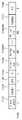
- FIG. 15shows an example of a TIM bitmap and an LMB element.
- Link mapping bitmapsare configured as many as the number of AIDs set to 1.
- a link mapping bitmap (LMB) for AID 12indicates that there is traffic for link1
- an LMB for AID 28indicates that there is traffic for link2 and link3.
- a TID bitmapmay be included. Each bit of the TID Bitmap is mapped to each TID. A bit set to 1 in the TID Bitmap indicates that there is traffic for the TID mapped to that bit.
- Method 1All bits of the Link Bitmap corresponding to a specific MLD are set to 1 (or 0).
- 16shows an example of indicating traffic for TIDs mapped to all links by setting all bits of the Link Bitmap to 1.
- the terminalcannot distinguish between traffic for TIDs mapped to a specific link or traffic for TIDs mapped to all links. In this case, an unnecessary overhead may occur due to a fixed overhead.
- an overhead increaseoccurs when the size of a bitmap configured per MLD is large (ie, when the number of links is large, for example, 5 or 8).
- FIG. 17shows an example of indicating traffic for TIDs mapped to all links by setting all bits of the Link Bitmap to 0.
- FIG. 17shows an example in which all bits are set to 0 to indicate traffic mapped to all links.
- all bits of the Link Bitmapare set to 0 to indicate that there is traffic mapped to all links.
- the LMB for AID 77indicates that it is in the TID mapped to links 1, 2, and 3, respectively.
- Method 2If there is only traffic mapped to all links, do not include Link Mapping Bitmap.
- the terminalwhen itself (non-AP MLD) is pointed to in the partial virtual bitmap of the TIM element, if the link bitmap is not additionally included in the beacon, the terminal (non-AP MLD) has traffic in which the AP MLD is mapped to all links. considered to be
- Link Mapping Bitmapa field indicating whether a Link Bitmap for a specific MLD exists (eg, Link bitmap present field) is included.
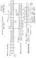
- FIG. 18shows an example of an LMB element further including a Link bitmap present field.
- the Link Mapping Bitmapincludes a Link Bitmap present field and a Link bitmap for each MLD.
- Link Bitmap presentit indicates whether there is a Link Bitmap for a specific MLD.
- the size of the Link Bitmap Present fieldis the number of bits set to 1 in the TIM Bitmap, the size of each Link Bitmap following the Link bitmap present field is 3 bits, and each bit indicates Link 1, 2, and 3.
- Link Bitmapsare included only for MLDs for AID 12, AID 35, and AID 77.
- the Link Bitmap of AID 12indicates that there is traffic for link 1
- the Link Bitmap of AID 35indicates that there is traffic on links 2 and 3
- the Link Bitmap of AID 77indicates that there is traffic on link 2.
- each bit of the Link bitmap presetis set to 0, so the Link Bitmap does not appear.
- the devices corresponding to AID 28 and AID 57are MLDs, it is determined that the AP has traffic for the TIDs mapped to all links.
- a non-MLD STAmay skip reading an element for the corresponding LMB.
- the size of the Link Bitmap for each MLDmay be variable, and length information for the Link Bitmap may be included in the LMB element. If length information is not included, the size of the Link Bitmap becomes the total number of links operated by the AP. 19 shows an example for this.
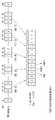
- FIG. 19shows an example of an LMB element further including a Link bitmap length field.
- Methods 1 and 2can effectively inform when there is only traffic for TIDs mapped to all links or when there is no traffic for TIDs mapped to all links and there is traffic for TIDs mapped to specific links.
- the bit for MLD for AID 77 in the Link Bitmap Present fieldis set to 1, and the corresponding Link Bitmap is included.
- the corresponding MLD(AID 77) can know that the AP has both traffic for TIDs mapped to all links and traffic for TIDs mapped to specific links. However, it is not possible to know which link the traffic for a specific link is mapped to.
- the first bit of the Link Bitmap for each MLDis used as a bit indicating whether there is traffic for the TID mapped to all links. 21 shows an example of this.
- 21shows an example of adding one more bit to the Link Bitmap indicated in the Link Bitmap Present field.
- the Link Bitmap for MLD for AID 12corresponds to the mapped TID for all links. It indicates that there is traffic for the TID mapped to link 1. Since the bit for all links in the Link Bitmap for MLD for AID 35 is set to 0 and the bit for links 2 and 3 is set to 1, the Link Bitmap for MLD for AID 35 is set to link 2 and link 3. Indicates that there is traffic for mapped TIDs.
- the Link Bitmap for MLD for AID 77is the same as the mapped TID for all links. Indicates that there is traffic for TIDs mapped to Link 1, Link 2, and Link 3.
- FIG. 22is a flowchart illustrating a procedure in which a transmitting MLD transmits traffic information for a TID mapped to all links or a specific link according to the present embodiment.
- the example of FIG. 22may be performed in a network environment in which a next-generation wireless LAN system (IEEE 802.11be or EHT wireless LAN system) is supported.
- the next-generation wireless LAN systemis a wireless LAN system improved from the 802.11ax system, and may satisfy backward compatibility with the 802.11ax system.
- This embodimentproposes a method and apparatus for delivering not only traffic for the MLD, but also traffic information for all links used by the MLD or traffic information for a TID mapped to a specific link.
- step S2210the transmission MLD (Multi-link Device) generates a beacon frame.
- step S2220the transmitting MLD transmits the beacon frame to the receiving MLD.
- the beacon frameincludes a Link Mapping Bitmap (LMB) element.
- the LMB elementincludes a first field and a second field.
- the first fieldincludes information on whether a link bitmap exists.
- the second fieldincludes information on a link bitmap for a specific received MLD.
- the information on the link bitmap for the specific reception MLDincludes first and second information.
- the first informationis information on whether or not traffic for a TID (Traffic Identifier) mapped to all links for the specific received MLD exists.
- the second informationis information on whether or not traffic for a TID mapped to a specific link for the specific reception MLD exists.
- the transmitting MLDcould deliver the buffered traffic for the receiving MLD through a partial virtual bitmap of a TIM (Traffic Indication Map) element in multi-link operation.
- This embodimentdefines a link bitmap for a specific reception MLD, so that the transmission MLD transmits buffered traffic for all links (first information) or a specific link (second information) used by the reception MLD through the link bitmap.
- the specific reception MLDmay be selected as a second reception MLD among the first reception MLDs based on the first field.
- the first reception MLDmay be a reception MLD for an association identifier (AID) corresponding to a bit set to 1 in a traffic indication map (TIM) bitmap.
- AIDassociation identifier
- TIMtraffic indication map
- the TIM bitmapconsists of 256 bits, and one AID is mapped to each bit. If there is a bit set to 1 in the TIM bitmap, the reception MLD can know that there is a reception MLD (non-AP MLD) to which the AID corresponding to the bit is allocated.
- the second reception MLDmay be a reception MLD corresponding to a bit set to 1 in the first field.
- the first fieldmay be a field indicating in a bitmap whether a link bitmap for each of the first received MLDs exists by allocating one bit to each of the first received MLDs. For example, in the TIM bitmap, first to fifth bits (5 bits) are set to 1, the first bit indicates AID 12, the second bit indicates AID 28, and the It is assumed that 3 bits indicate AID 35, the fourth bit indicates AID 57, and the fifth bit indicates AID 77.
- the receiving MLDis received MLD #1 for AID 12, received MLD #2 for AID 28, received MLD #3 for AID 35, received MLD #4 for AID 57, and received MLD #5 for AID 77 can be seen to exist.
- the first fieldmay be generated as a 5-bit bitmap by allocating one bit to each of the indicated five received MLDs (the first received MLD). That is, the size of the first field may be equal to the number of bits set to 1 in the TIM bitmap.
- the second fieldmay include only information on link bitmaps for the received MLDs #1, #3, and #5.
- this embodimentproposes a method of respectively delivering all links and/or traffic for a specific link with respect to the specific receiving MLD through information on a link bitmap for the specific receiving MLD.
- the first informationincludes one bit
- the one bitmay be set to 1. That is, this embodiment proposes a method of using the first bit of the link bitmap for the specific received MLD as a bit indicating whether there is traffic for the TID mapped to all links.
- the second informationincludes a first bit for the first link; a second bit for the second link and a third bit for the third link.
- the first and second bitsmay be set to 1, and the third bit may be set to 0.
- a bit indicating that there is traffic for the TID mapped to all links(the first information) and a separate bit or bitmap (second information) are configured to provide traffic for the TID mapped to a specific link Suggests a way to inform that there is also.
- the LMB elementmay further include a third field.
- the third fieldmay include information on the length of the link bitmap for the specific reception MLD.
- the length of the link bitmap for the specific reception MLDmay be determined based on the number of links used by the specific reception MLD. For example, if there are three links used by the specific reception MLD, the length of the link bitmap for the specific reception MLD may be 3 bits. Alternatively, when the information on the link bitmap for the specific reception MLD further includes the first information (1 bit), the length of the link bitmap for the specific reception MLD may be 4 bits.
- FIG. 23is a flowchart illustrating a procedure in which a receiving MLD receives traffic information for a TID mapped to all links or a specific link according to the present embodiment.
- the example of FIG. 23may be performed in a network environment in which a next-generation wireless LAN system (IEEE 802.11be or EHT wireless LAN system) is supported.
- the next-generation wireless LAN systemis a wireless LAN system improved from the 802.11ax system, and may satisfy backward compatibility with the 802.11ax system.
- This embodimentproposes a method and apparatus for delivering not only traffic for the MLD, but also traffic information for all links used by the MLD or traffic information for a TID mapped to a specific link.
- step S2310the receiving multi-link device (MLD) receives a beacon frame from the transmitting MLD.
- step S2320the receiving MLD decodes the beacon frame.
- the beacon frameincludes a Link Mapping Bitmap (LMB) element.
- the LMB elementincludes a first field and a second field.
- the first fieldincludes information on whether a link bitmap exists.
- the second fieldincludes information on a link bitmap for a specific received MLD.
- the information on the link bitmap for the specific reception MLDincludes first and second information.
- the first informationis information on whether or not traffic for a TID (Traffic Identifier) mapped to all links for the specific received MLD exists.
- the second informationis information on whether or not traffic for a TID mapped to a specific link for the specific reception MLD exists.
- the transmitting MLDcould deliver the buffered traffic for the receiving MLD through a partial virtual bitmap of a TIM (Traffic Indication Map) element in multi-link operation.
- This embodimentdefines a link bitmap for a specific reception MLD, so that the transmission MLD transmits buffered traffic for all links (first information) or a specific link (second information) used by the reception MLD through the link bitmap.
- the specific reception MLDmay be selected as a second reception MLD among the first reception MLDs based on the first field.
- the first reception MLDmay be a reception MLD for an association identifier (AID) corresponding to a bit set to 1 in a traffic indication map (TIM) bitmap.
- AIDassociation identifier
- TIMtraffic indication map
- the TIM bitmapconsists of 256 bits, and one AID is mapped to each bit. If there is a bit set to 1 in the TIM bitmap, the reception MLD can know that there is a reception MLD (non-AP MLD) to which an AID corresponding to the bit is allocated.
- the second reception MLDmay be a reception MLD corresponding to a bit set to 1 in the first field.
- the first fieldmay be a field indicating in a bitmap whether a link bitmap for each of the first received MLDs exists by allocating one bit to each of the first received MLDs. For example, in the TIM bitmap, first to fifth bits (5 bits) are set to 1, the first bit indicates AID 12, the second bit indicates AID 28, and the It is assumed that 3 bits indicate AID 35, the fourth bit indicates AID 57, and the fifth bit indicates AID 77.
- the receiving MLDis received MLD #1 for AID 12, received MLD #2 for AID 28, received MLD #3 for AID 35, received MLD #4 for AID 57, and received MLD #5 for AID 77 can be seen to exist.
- the first fieldmay be generated as a 5-bit bitmap by allocating one bit to each of the indicated five reception MLDs (the first reception MLDs). That is, the size of the first field may be the same as the number of bits set to 1 in the TIM bitmap.
- the second fieldmay include only information on link bitmaps for the received MLDs #1, #3, and #5.
- this embodimentproposes a method of respectively delivering all links and/or traffic for a specific link with respect to the specific receiving MLD through information on a link bitmap for the specific receiving MLD.
- the first informationincludes one bit
- the one bitmay be set to 1. That is, this embodiment proposes a method of using the first bit of the link bitmap for the specific received MLD as a bit indicating whether there is traffic for the TID mapped to all links.
- the second informationincludes a first bit for the first link; a second bit for the second link and a third bit for the third link.
- the first and second bitsmay be set to 1, and the third bit may be set to 0.
- a bit indicating that there is traffic for the TID mapped to all links(the first information) and a separate bit or bitmap (second information) are configured to provide traffic for the TID mapped to a specific link Suggests a way to inform that there is also.
- the LMB elementmay further include a third field.
- the third fieldmay include information on the length of the link bitmap for the specific reception MLD.
- the length of the link bitmap for the specific reception MLDmay be determined based on the number of links used by the specific reception MLD. For example, if there are three links used by the specific reception MLD, the length of the link bitmap for the specific reception MLD may be 3 bits. Alternatively, when the information on the link bitmap for the specific reception MLD further includes the first information (1 bit), the length of the link bitmap for the specific reception MLD may be 4 bits.
- the technical features of the present specification described abovemay be applied to various devices and methods.
- the above-described technical features of the present specificationmay be performed/supported through the apparatus of FIGS. 1 and/or 11 .
- the technical features of the present specification described abovemay be applied only to a part of FIGS. 1 and/or 11 .
- the technical features of the present specification described aboveare implemented based on the processing chips 114 and 124 of FIG. 1 , or implemented based on the processors 111 and 121 and the memories 112 and 122 of FIG. 1 , or , may be implemented based on the processor 610 and the memory 620 of FIG. 11 .
- the apparatus hereinmay receive a beacon frame from a transmitting multi-link device (MLD); and decodes the beacon frame.
- MLDtransmitting multi-link device
- CRMcomputer readable medium
- CRM proposed by the present specificationis at least one computer readable medium including at least one computer readable medium including instructions based on being executed by at least one processor.
- the CRMmay include: receiving a beacon frame from a transmitting multi-link device (MLD); and instructions for performing operations including decoding the beacon frame.
- the instructions stored in the CRM of the present specificationmay be executed by at least one processor.
- At least one processor related to CRM in the present specificationmay be the processors 111 and 121 or the processing chips 114 and 124 of FIG. 1 , or the processor 610 of FIG. 11 .
- the CRM of the present specificationmay be the memories 112 and 122 of FIG. 1 , the memory 620 of FIG. 11 , or a separate external memory/storage medium/disk.
- Machine learningrefers to a field that defines various problems dealt with in the field of artificial intelligence and studies methodologies to solve them. do.
- Machine learningis also defined as an algorithm that improves the performance of a certain task through constant experience.
- An artificial neural networkis a model used in machine learning, and may refer to an overall model having problem-solving ability, which is composed of artificial neurons (nodes) that form a network by combining synapses.
- An artificial neural networkmay be defined by a connection pattern between neurons of different layers, a learning process that updates model parameters, and an activation function that generates an output value.
- the artificial neural networkmay include an input layer, an output layer, and optionally one or more hidden layers. Each layer includes one or more neurons, and the artificial neural network may include neurons and synapses connecting neurons. In the artificial neural network, each neuron may output a function value of an activation function for input signals, weights, and biases input through synapses.
- a model parametermeans a parameter determined through learning, and includes the weight of the synaptic connection and the bias of the neuron.
- the hyperparameterrefers to a parameter that must be set before learning in a machine learning algorithm, and includes a learning rate, the number of iterations, a mini-batch size, an initialization function, and the like.
- the purpose of learning the artificial neural networkcan be seen as determining the model parameters that minimize the loss function.
- the loss functionmay be used as an index for determining optimal model parameters in the learning process of the artificial neural network.
- Machine learningcan be classified into supervised learning, unsupervised learning, and reinforcement learning according to a learning method.
- Supervised learningrefers to a method of training an artificial neural network in a state in which a label for the training data is given, and the label is the correct answer (or result value) that the artificial neural network should infer when the training data is input to the artificial neural network.
- Unsupervised learningmay refer to a method of training an artificial neural network in a state where no labels are given for training data.
- Reinforcement learningcan refer to a learning method in which an agent defined in an environment learns to select an action or sequence of actions that maximizes the cumulative reward in each state.
- machine learningimplemented as a deep neural network (DNN) including a plurality of hidden layers is also called deep learning, and deep learning is a part of machine learning.
- DNNdeep neural network
- machine learningis used in a sense including deep learning.
- a robotcan mean a machine that automatically handles or operates a task given by its own capabilities.
- a robot having a function of recognizing an environment and performing an operation by self-judgmentmay be referred to as an intelligent robot.
- Robotscan be classified into industrial, medical, home, military, etc. depending on the purpose or field of use.
- the robotmay be provided with a driving unit including an actuator or a motor to perform various physical operations such as moving the robot joints.
- the movable robotincludes a wheel, a brake, a propeller, and the like in the driving unit, and may travel on the ground or fly in the air through the driving unit.
- the extended realityis a generic term for virtual reality (VR), augmented reality (AR), and mixed reality (MR).
- VR technologyprovides only CG images of objects or backgrounds in the real world
- AR technologyprovides virtual CG images on top of images of real objects
- MR technologyis a computer that mixes and combines virtual objects in the real world. graphic technology.
- MR technologyis similar to AR technology in that it shows both real and virtual objects. However, there is a difference in that in AR technology, a virtual object is used in a form that complements a real object, whereas in MR technology, a virtual object and a real object are used with equal characteristics.
- HMDHead-Mount Display
- HUDHead-Up Display
- mobile phonetablet PC, laptop, desktop, TV, digital signage, etc.
Landscapes
- Engineering & Computer Science (AREA)
- Computer Networks & Wireless Communication (AREA)
- Signal Processing (AREA)
- Mobile Radio Communication Systems (AREA)
Abstract
Description
Translated fromKorean본 명세서는 무선랜 시스템에서 멀티 링크 동작에 관한 것으로, 보다 상세하게는, 모든 링크 또는 특정 링크에 대한 트래픽을 수신하는 방법 및 장치에 관한 것이다.This specification relates to multi-link operation in a WLAN system, and more particularly, to a method and apparatus for receiving traffic for all links or a specific link.
WLAN(wireless local area network)은 다양한 방식으로 개선되어왔다. 예를 들어, IEEE 802.11ax 표준은 OFDMA(orthogonal frequency division multiple access) 및 DL MU MIMO(downlink multi-user multiple input, multiple output) 기법을 사용하여 개선된 통신 환경을 제안했다.A wireless local area network (WLAN) has been improved in various ways. For example, the IEEE 802.11ax standard proposes an improved communication environment using OFDMA (orthogonal frequency division multiple access) and DL MU downlink multi-user multiple input, multiple output (MIMO) techniques.
본 명세서는 새로운 통신 표준에서 활용 가능한 기술적 특징을 제안한다. 예를 들어, 새로운 통신 표준은 최근에 논의 중인 EHT(Extreme high throughput) 규격일 수 있다. EHT 규격은 새롭게 제안되는 증가된 대역폭, 개선된 PPDU(PHY layer protocol data unit) 구조, 개선된 시퀀스, HARQ(Hybrid automatic repeat request) 기법 등을 사용할 수 있다. EHT 규격은 IEEE 802.11be 규격으로 불릴 수 있다.This specification proposes technical features that can be used in a new communication standard. For example, the new communication standard may be an Extreme High Throughput (EHT) specification that is being discussed recently. The EHT standard may use a newly proposed increased bandwidth, an improved PHY layer protocol data unit (PPDU) structure, an improved sequence, a hybrid automatic repeat request (HARQ) technique, and the like. The EHT standard may be referred to as an IEEE 802.11be standard.
새로운 무선랜 규격에서는 증가된 개수의 공간 스트림이 사용될 수 있다. 이 경우, 증가된 개수의 공간 스트림을 적절히 사용하기 위해 무선랜 시스탬 내에서의 시그널링 기법이 개선되어야 할 수 있다.An increased number of spatial streams may be used in the new wireless LAN standard. In this case, in order to properly use the increased number of spatial streams, a signaling technique in the WLAN system may need to be improved.
본 명세서는 무선랜 시스템에서 모든 링크 또는 특정 링크에 대한 트래픽을 수신하는 방법 및 장치를 제안한다.The present specification proposes a method and apparatus for receiving traffic for all links or a specific link in a WLAN system.
본 명세서의 일례는 모든 링크 또는 특정 링크에 대한 트래픽을 수신하는 방법을 제안한다.An example herein proposes a method for receiving traffic for all links or a specific link.
본 실시예는 차세대 무선랜 시스템(IEEE 802.11be 또는 EHT 무선랜 시스템)이 지원되는 네트워크 환경에서 수행될 수 있다. 상기 차세대 무선랜 시스템은 802.11ax 시스템을 개선한 무선랜 시스템으로 802.11ax 시스템과 하위 호환성(backward compatibility)을 만족할 수 있다.This embodiment may be performed in a network environment in which a next-generation wireless LAN system (IEEE 802.11be or EHT wireless LAN system) is supported. The next-generation wireless LAN system is a wireless LAN system improved from the 802.11ax system, and may satisfy backward compatibility with the 802.11ax system.
본 실시예는 MLD에 대한 트래픽뿐만 아니라 MLD가 사용하는 모든 링크 또는 특정 링크에 매핑된 TID에 대한 트래픽 정보를 전달하는 방법 및 장치를 제안한다.This embodiment proposes a method and apparatus for delivering not only traffic for the MLD, but also traffic information for all links used by the MLD or traffic information for a TID mapped to a specific link.
수신 MLD(Multi-link Device)는 송신 MLD로부터 비콘 프레임을 수신한다.A receiving multi-link device (MLD) receives a beacon frame from a transmitting MLD.
상기 수신 MLD는 상기 비콘 프레임을 복호한다.The receiving MLD decodes the beacon frame.
상기 비콘 프레임은 LMB(Link Mapping Bitmap) 요소를 포함한다. 상기 LMB 요소는 제1 필드 및 제2 필드를 포함한다. 상기 제1 필드는 링크 비트맵이 존재하는지 여부에 대한 정보를 포함한다. 상기 제2 필드는 특정 수신 MLD에 대한 링크 비트맵에 대한 정보를 포함한다.The beacon frame includes a Link Mapping Bitmap (LMB) element. The LMB element includes a first field and a second field. The first field includes information on whether a link bitmap exists. The second field includes information on a link bitmap for a specific received MLD.
상기 특정 수신 MLD에 대한 링크 비트맵에 대한 정보는 제1 및 제2 정보를 포함한다. 상기 제1 정보는 상기 특정 수신 MLD에 대해 모든 링크에 매핑된 TID(Traffic Identifier)에 대한 트래픽이 존재하는지 여부에 대한 정보이다. 상기 제2 정보는 상기 특정 수신 MLD에 대해 특정 링크에 매핑된 TID에 대한 트래픽이 존재하는지 여부에 대한 정보이다.The information on the link bitmap for the specific reception MLD includes first and second information. The first information is information on whether or not traffic for a TID (Traffic Identifier) mapped to all links for the specific received MLD exists. The second information is information on whether or not traffic for a TID mapped to a specific link for the specific reception MLD exists.
기존에는 송신 MLD가 멀티 링크 동작에서 TIM(Traffic Indication Map) 요소의 부분 가상 비트맵을 통해 수신 MLD에 대한 버퍼된 트래픽을 전달할 수 있었다. 본 실시예는 특정 수신 MLD에 대한 링크 비트맵을 정의하여 송신 MLD가 상기 링크 비트맵을 통해 수신 MLD가 사용하는 모든 링크(제1 정보) 또는 특정 링크(제2 정보)에 대한 버퍼된 트래픽이 있음을 알려주는 방법을 제안한다.Conventionally, the transmitting MLD could deliver the buffered traffic for the receiving MLD through a partial virtual bitmap of a TIM (Traffic Indication Map) element in multi-link operation. This embodiment defines a link bitmap for a specific reception MLD, so that the transmission MLD transmits buffered traffic for all links (first information) or a specific link (second information) used by the reception MLD through the link bitmap. We suggest a way to let you know that
본 명세서에서 제안된 실시예에 따르면, 수신 MLD는 자신이 사용하는 모든 링크 또는 특정 링크에 대한 트래픽이 있음을 빠르게 알 수 있어 효율적으로 트래픽 관리를 할 수 있다는 효과가 있다.According to the embodiment proposed in this specification, the receiving MLD can quickly know that there is traffic for all links or a specific link used by the receiving MLD, so that it can efficiently manage traffic.
도 1은 본 명세서의 송신 장치 및/또는 수신 장치의 일례를 나타낸다.1 shows an example of a transmitting apparatus and/or a receiving apparatus of the present specification.
도 2는 무선랜(WLAN)의 구조를 나타낸 개념도이다.2 is a conceptual diagram illustrating the structure of a wireless LAN (WLAN).
도 3은 일반적인 링크 셋업(link setup) 과정을 설명하는 도면이다.3 is a view for explaining a general link setup process.
도 4는 IEEE 규격에서 사용되는 PPDU의 일례를 도시한 도면이다.4 is a diagram illustrating an example of a PPDU used in the IEEE standard.
도 5는 UL-MU에 따른 동작을 나타낸다.5 shows an operation according to UL-MU.
도 6은 트리거 프레임의 일례를 나타낸다.6 shows an example of a trigger frame.
도 7은 트리거 프레임의 공통 정보(common information) 필드의 일례를 나타낸다.7 shows an example of a common information field of a trigger frame.
도 8은 사용자 정보(per user information) 필드에 포함되는 서브 필드의 일례를 나타낸다.8 shows an example of a subfield included in a per user information field.
도 9는 UORA 기법의 기술적 특징을 설명한다.9 illustrates the technical features of the UORA technique.
도 10은 본 명세서에 사용되는 PPDU의 일례를 나타낸다.10 shows an example of a PPDU used in this specification.
도 11은 본 명세서의 송신 장치 및/또는 수신 장치의 변형된 일례를 나타낸다.11 shows a modified example of a transmitting apparatus and/or a receiving apparatus of the present specification.
도 12는 TID-To-Link 매핑 요소 포맷의 일례를 나타낸다.12 shows an example of a TID-To-Link mapping element format.
도 13은 Multi-Link Traffic 요소 포맷의 일례를 나타낸다.13 shows an example of a Multi-Link Traffic element format.
도 14는 Multi-Link Traffic 요소 포맷의 일례를 나타낸다.14 shows an example of a Multi-Link Traffic element format.
도 15는 TIM 비트맵 및 LMB 요소의 일례를 나타낸다.15 shows an example of a TIM bitmap and an LMB element.
도 16은 Link Bitmap의 모든 비트를 1로 설정하여 모든 링크에 매핑된 TID에 대한 트래픽을 나타내는 일례를 나타낸다.16 shows an example of indicating traffic for TIDs mapped to all links by setting all bits of the Link Bitmap to 1.
도 17은 Link Bitmap의 모든 비트를 0으로 설정하여 모든 링크에 매핑된 TID에 대한 트래픽을 나타내는 일례를 나타낸다.17 shows an example of indicating traffic for TIDs mapped to all links by setting all bits of the Link Bitmap to 0. Referring to FIG.
도 18은 Link bitmap present 필드를 더 포함하는 LMB 요소의 일례를 나타낸다.18 shows an example of an LMB element further including a Link bitmap present field.
도 19는 Link bitmap length 필드를 더 포함하는 LMB 요소의 일례를 나타낸다.19 shows an example of an LMB element further including a Link bitmap length field.
도 20은 Link Bitmap Present 필드에서 지시된 Link Bitmap의 모든 비트를 1로 설정하는 일례를 나타낸다.20 shows an example of setting all bits of the Link Bitmap indicated in the Link Bitmap Present field to 1.
도 21은 Link Bitmap Present 필드에서 지시된 Link Bitmap에 하나의 비트를 더 추가하는 일례를 나타낸다.21 shows an example of adding one more bit to the Link Bitmap indicated in the Link Bitmap Present field.
도 22는 본 실시예에 따른 송신 MLD가 모든 링크 또는 특정 링크에 매핑된 TID에 대한 트래픽 정보를 송신하는 절차를 도시한 흐름도이다.22 is a flowchart illustrating a procedure in which a transmitting MLD transmits traffic information for a TID mapped to all links or a specific link according to the present embodiment.
도 23은 본 실시예에 따른 수신 MLD가 모든 링크 또는 특정 링크에 매핑된 TID에 대한 트래픽 정보를 수신하는 절차를 도시한 흐름도이다.23 is a flowchart illustrating a procedure in which a receiving MLD receives traffic information for a TID mapped to all links or a specific link according to the present embodiment.
본 명세서에서 “A 또는 B(A or B)”는 “오직 A”, “오직 B” 또는 “A와 B 모두”를 의미할 수 있다. 달리 표현하면, 본 명세서에서 “A 또는 B(A or B)”는 “A 및/또는 B(A and/or B)”으로 해석될 수 있다. 예를 들어, 본 명세서에서 “A, B 또는 C(A, B or C)”는 “오직 A”, “오직 B”, “오직 C”또는 “A, B 및 C의 임의의 모든 조합(any combination of A, B and C)”를 의미할 수 있다.In this specification, “A or B (A or B)” may mean “only A”, “only B” or “both A and B”. In other words, in the present specification, “A or B (A or B)” may be interpreted as “A and/or B (A and/or B)”. For example, “A, B or C (A, B or C)” herein means “only A,” “only B,” “only C,” or “any and any combination of A, B and C. combination of A, B and C)”.
본 명세서에서 사용되는 슬래쉬(/)나 쉼표(comma)는 “및/또는(and/or)”을 의미할 수 있다. 예를 들어, “A/B”는 “및/또는 B”를 의미할 수 있다. 이에 따라 “A/B”는 “오직 A”, “오직 B”, 또는 “A와 B 모두”를 의미할 수 있다. 예를 들어, “A, B, C”는 “A, B 또는 C”를 의미할 수 있다.A slash (/) or a comma (comma) used herein may mean “and/or”. For example, “A/B” may mean “and/or B”. Accordingly, “A/B” may mean “only A”, “only B”, or “both A and B”. For example, “A, B, C” may mean “A, B, or C”.
본 명세서에서 “적어도 하나의 A 및 B(at least one of A and B)”는, “오직 A”“오직 B” 또는 “A와 B 모두”를 의미할 수 있다. 또한, 본 명세서에서 “적어도 하나의 A 또는 B(at least one of A or B)”나 “적어도 하나의 A 및/또는 B(at least one of A and/or B)”라는 표현은 “적어도 하나의 A 및 B(at least one of A and B)”와 동일하게 해석될 수 있다.As used herein, “at least one of A and B” may mean “only A”, “only B” or “both A and B”. In addition, in this specification, the expression “at least one of A or B” or “at least one of A and/or B” means “at least one It can be interpreted the same as “at least one of A and B”.
또한, 본 명세서에서 “적어도 하나의 A, B 및 C(at least one of A, B and C)”는, “오직 A”, “오직 B”, “오직 C”또는 “A, B 및 C의 임의의 모든 조합(any combination of A, B and C)”를 의미할 수 있다. 또한, “적어도 하나의 A, B 또는 C(at least one of A, B or C)”나 “적어도 하나의 A, B 및/또는 C(at least one of A, B and/or C)”는 “적어도 하나의 A, B 및 C(at least one of A, B and C)”를 의미할 수 있다.Also, in this specification, “at least one of A, B and C” means “only A”, “only B”, “only C” or “of A, B and C”. any combination of A, B and C”. Also, “at least one of A, B or C” or “at least one of A, B and/or C” means may mean “at least one of A, B and C”.
또한, 본 명세서에서 사용되는 괄호는 “예를 들어(for example)”를 의미할 수 있다. 구체적으로, “제어 정보(EHT-Signal)”로 표시된 경우, “제어 정보”의 일례로 “EHT-Signal”이 제안된 것일 수 있다. 달리 표현하면 본 명세서의 “제어 정보”는 “EHT-Signal”로 제한(limit)되지 않고, “EHT-Signal”이 “제어 정보”의 일례로 제안될 것일 수 있다. 또한, “제어 정보(즉, EHT-signal)”로 표시된 경우에도, “제어 정보”의 일례로 “EHT-Signal”가 제안된 것일 수 있다.In addition, parentheses used herein may mean “for example”. Specifically, when displayed as “control information (EHT-Signal)”, “EHT-Signal” may be proposed as an example of “control information”. In other words, “control information” of the present specification is not limited to “EHT-Signal”, and “EHT-Signal” may be proposed as an example of “control information”. Also, even when displayed as “control information (ie, EHT-signal)”, “EHT-Signal” may be proposed as an example of “control information”.
본 명세서에서 하나의 도면 내에서 개별적으로 설명되는 기술적 특징은, 개별적으로 구현될 수도 있고, 동시에 구현될 수도 있다.In this specification, technical features that are individually described within one drawing may be implemented individually or simultaneously.
본 명세서의 이하의 일례는 다양한 무선 통신시스템에 적용될 수 있다. 예를 들어, 본 명세서의 이하의 일례는 무선랜(wireless local area network, WLAN) 시스템에 적용될 수 있다. 예를 들어, 본 명세서는 IEEE 802.11a/g/n/ac의 규격이나, IEEE 802.11ax 규격에 적용될 수 있다. 또한 본 명세서는 새롭게 제안되는 EHT 규격 또는 IEEE 802.11be 규격에도 적용될 수 있다. 또한 본 명세서의 일례는 EHT 규격 또는 IEEE 802.11be를 개선(enhance)한 새로운 무선랜 규격에도 적용될 수 있다. 또한 본 명세서의 일례는 이동 통신 시스템에 적용될 수 있다. 예를 들어, 3GPP(3rd Generation Partnership Project) 규격에 기반하는 LTE(Long Term Evolution) 및 그 진화(evoluation)에 기반하는 이동 통신 시스템에 적용될 수 있다. 또한, 본 명세서의 일례는 3GPP 규격에 기반하는 5G NR 규격의 통신 시스템에 적용될 수 있다.The following examples of the present specification may be applied to various wireless communication systems. For example, the following example of the present specification may be applied to a wireless local area network (WLAN) system. For example, the present specification may be applied to the IEEE 802.11a/g/n/ac standard or the IEEE 802.11ax standard. In addition, this specification may be applied to the newly proposed EHT standard or IEEE 802.11be standard. In addition, an example of the present specification may be applied to the EHT standard or a new wireless LAN standard that is an enhancement of IEEE 802.11be. Also, an example of the present specification may be applied to a mobile communication system. For example, it may be applied to a mobile communication system based on Long Term Evolution (LTE) based on the 3rd Generation Partnership Project (3GPP) standard and its evolution. In addition, an example of the present specification may be applied to a communication system of the 5G NR standard based on the 3GPP standard.
이하 본 명세서의 기술적 특징을 설명하기 위해 본 명세서가 적용될 수 있는 기술적 특징을 설명한다.Hereinafter, technical features to which the present specification can be applied in order to describe the technical features of the present specification will be described.
도 1은 본 명세서의 송신 장치 및/또는 수신 장치의 일례를 나타낸다.1 shows an example of a transmitting apparatus and/or a receiving apparatus of the present specification.
도 1의 일례는 이하에서 설명되는 다양한 기술적 특징을 수행할 수 있다. 도 1은 적어도 하나의 STA(station)에 관련된다. 예를 들어, 본 명세서의 STA(110, 120)은 이동 단말(mobile terminal), 무선 기기(wireless device), 무선 송수신 유닛(Wireless Transmit/Receive Unit; WTRU), 사용자 장비(User Equipment; UE), 이동국(Mobile Station; MS), 이동 가입자 유닛(Mobile Subscriber Unit) 또는 단순히 유저(user) 등의 다양한 명칭으로도 불릴 수 있다. 본 명세서의 STA(110, 120)은 네트워크, 기지국(Base Station), Node-B, AP(Access Point), 리피터, 라우터, 릴레이 등의 다양한 명칭으로 불릴 수 있다. 본 명세서의 STA(110, 120)은 수신 장치, 송신 장치, 수신 STA, 송신 STA, 수신 Device, 송신 Device 등의 다양한 명칭으로 불릴 수 있다.The example of FIG. 1 may perform various technical features described below. 1 relates to at least one STA (station). For example, the
예를 들어, STA(110, 120)은 AP(access Point) 역할을 수행하거나 non-AP 역할을 수행할 수 있다. 즉, 본 명세서의 STA(110, 120)은 AP 및/또는 non-AP의 기능을 수행할 수 있다. 본 명세서에서 AP는 AP STA으로도 표시될 수 있다.For example, the
본 명세서의 STA(110, 120)은 IEEE 802.11 규격 이외의 다양한 통신 규격을 함께 지원할 수 있다. 예를 들어, 3GPP 규격에 따른 통신 규격(예를 들어, LTE, LTE-A, 5G NR 규격)등을 지원할 수 있다. 또한 본 명세서의 STA은 휴대 전화, 차량(vehicle), 개인용 컴퓨터 등의 다양한 장치로 구현될 수 있다. 또한, 본 명세서의 STA은 음성 통화, 영상 통화, 데이터 통신, 자율 주행(Self-Driving, Autonomous-Driving) 등의 다양한 통신 서비스를 위한 통신을 지원할 수 있다.The
본 명세서에서 STA(110, 120)은 IEEE 802.11 표준의 규정을 따르는 매체 접속 제어(medium access control, MAC)와 무선 매체에 대한 물리 계층(Physical Layer) 인터페이스를 포함할 수 있다.In this specification, the
도 1의 부도면 (a)를 기초로 STA(110, 120)을 설명하면 이하와 같다.The
제1 STA(110)은 프로세서(111), 메모리(112) 및 트랜시버(113)를 포함할 수 있다. 도시된 프로세서, 메모리 및 트랜시버는 각각 별도의 칩으로 구현되거나, 적어도 둘 이상의 블록/기능이 하나의 칩을 통해 구현될 수 있다.The
제1 STA의 트랜시버(113)는 신호의 송수신 동작을 수행한다. 구체적으로, IEEE 802.11 패킷(예를 들어, IEEE 802.11a/b/g/n/ac/ax/be 등)을 송수신할 수 있다.The
예를 들어, 제1 STA(110)은 AP의 의도된 동작을 수행할 수 있다. 예를 들어, AP의 프로세서(111)는 트랜시버(113)를 통해 신호를 수신하고, 수신 신호를 처리하고, 송신 신호를 생성하고, 신호 송신을 위한 제어를 수행할 수 있다. AP의 메모리(112)는 트랜시버(113)를 통해 수신된 신호(즉, 수신 신호)를 저장할 수 있고, 트랜시버를 통해 송신될 신호(즉, 송신 신호)를 저장할 수 있다.For example, the
예를 들어, 제2 STA(120)은 Non-AP STA의 의도된 동작을 수행할 수 있다. 예를 들어, non-AP의 트랜시버(123)는 신호의 송수신 동작을 수행한다. 구체적으로, IEEE 802.11 패킷(예를 들어, IEEE 802.11a/b/g/n/ac/ax/be 등)을 송수신할 수 있다.For example, the
예를 들어, Non-AP STA의 프로세서(121)는 트랜시버(123)를 통해 신호를 수신하고, 수신 신호를 처리하고, 송신 신호를 생성하고, 신호 송신을 위한 제어를 수행할 수 있다. Non-AP STA의 메모리(122)는 트랜시버(123)를 통해 수신된 신호(즉, 수신 신호)를 저장할 수 있고, 트랜시버를 통해 송신될 신호(즉, 송신 신호)를 저장할 수 있다.For example, the
예를 들어, 이하의 명세서에서 AP로 표시된 장치의 동작은 제1 STA(110) 또는 제2 STA(120)에서 수행될 수 있다. 예를 들어 제1 STA(110)이 AP인 경우, AP로 표시된 장치의 동작은 제1 STA(110)의 프로세서(111)에 의해 제어되고, 제1 STA(110)의 프로세서(111)에 의해 제어되는 트랜시버(113)를 통해 관련된 신호가 송신되거나 수신될 수 있다. 또한, AP의 동작에 관련된 제어 정보나 AP의 송신/수신 신호는 제1 STA(110)의 메모리(112)에 저장될 수 있다. 또한, 제2 STA(110)이 AP인 경우, AP로 표시된 장치의 동작은 제2 STA(120)의 프로세서(121)에 의해 제어되고, 제2 STA(120)의 프로세서(121)에 의해 제어되는 트랜시버(123)를 통해 관련된 신호가 송신되거나 수신될 수 있다. 또한, AP의 동작에 관련된 제어 정보나 AP의 송신/수신 신호는 제2 STA(110)의 메모리(122)에 저장될 수 있다.For example, an operation of a device indicated as an AP in the following specification may be performed by the
예를 들어, 이하의 명세서에서 non-AP(또는 User-STA)로 표시된 장치의 동작은 제 STA(110) 또는 제2 STA(120)에서 수행될 수 있다. 예를 들어 제2 STA(120)이 non-AP인 경우, non-AP로 표시된 장치의 동작은 제2 STA(120)의 프로세서(121)에 의해 제어되고, 제2 STA(120)의 프로세서(121)에 의해 제어되는 트랜시버(123)를 통해 관련된 신호가 송신되거나 수신될 수 있다. 또한, non-AP의 동작에 관련된 제어 정보나 AP의 송신/수신 신호는 제2 STA(120)의 메모리(122)에 저장될 수 있다. 예를 들어 제1 STA(110)이 non-AP인 경우, non-AP로 표시된 장치의 동작은 제1 STA(110)의 프로세서(111)에 의해 제어되고, 제1 STA(120)의 프로세서(111)에 의해 제어되는 트랜시버(113)를 통해 관련된 신호가 송신되거나 수신될 수 있다. 또한, non-AP의 동작에 관련된 제어 정보나 AP의 송신/수신 신호는 제1 STA(110)의 메모리(112)에 저장될 수 있다.For example, an operation of a device indicated as a non-AP (or User-STA) in the following specification may be performed by the
이하의 명세서에서 (송신/수신) STA, 제1 STA, 제2 STA, STA1, STA2, AP, 제1 AP, 제2 AP, AP1, AP2, (송신/수신) Terminal, (송신/수신) device, (송신/수신) apparatus, 네트워크 등으로 불리는 장치는 도 1의 STA(110, 120)을 의미할 수 있다. 예를 들어, 구체적인 도면 부호 없이 (송신/수신) STA, 제1 STA, 제2 STA, STA1, STA2, AP, 제1 AP, 제2 AP, AP1, AP2, (송신/수신) Terminal, (송신/수신) device, (송신/수신) apparatus, 네트워크 등으로 표시된 장치도 도 1의 STA(110, 120)을 의미할 수 있다. 예를 들어, 이하의 일례에서 다양한 STA이 신호(예를 들어, PPPDU)를 송수신하는 동작은 도 1의 트랜시버(113, 123)에서 수행되는 것일 수 있다. 또한, 이하의 일례에서 다양한 STA이 송수신 신호를 생성하거나 송수신 신호를 위해 사전에 데이터 처리나 연산을 수행하는 동작은 도 1의 프로세서(111, 121)에서 수행되는 것일 수 있다. 예를 들어, 송수신 신호를 생성하거나 송수신 신호를 위해 사전에 데이터 처리나 연산을 수행하는 동작의 일례는, 1) PPDU 내에 포함되는 서브 필드(SIG, STF, LTF, Data) 필드의 비트 정보를 결정/획득/구성/연산/디코딩/인코딩하는 동작, 2) PPDU 내에 포함되는 서브 필드(SIG, STF, LTF, Data) 필드를 위해 사용되는 시간 자원이나 주파수 자원(예를 들어, 서브캐리어 자원) 등을 결정/구성/회득하는 동작, 3) PPDU 내에 포함되는 서브 필드(SIG, STF, LTF, Data) 필드를 위해 사용되는 특정한 시퀀스(예를 들어, 파일럿 시퀀스, STF/LTF 시퀀스, SIG에 적용되는 엑스트라 시퀀스) 등을 결정/구성/회득하는 동작, 4) STA에 대해 적용되는 전력 제어 동작 및/또는 파워 세이빙 동작, 5) ACK 신호의 결정/획득/구성/연산/디코딩/인코딩 등에 관련된 동작을 포함할 수 있다. 또한, 이하의 일례에서 다양한 STA이 송수신 신호의 결정/획득/구성/연산/디코딩/인코딩을 위해 사용하는 다양한 정보(예를 들어, 필드/서브필드/제어필드/파라미터/파워 등에 관련된 정보)는 도 1의 메모리(112, 122)에 저장될 수 있다.In the following specification (transmission / reception) STA, first STA, second STA, STA1, STA2, AP, first AP, second AP, AP1, AP2, (transmission / reception) Terminal, (transmission / reception) device , (transmitting/receiving) apparatus, a device called a network, etc. may refer to the
상술한 도 1의 부도면 (a)의 장치/STA는 도 1의 부도면 (b)와 같이 변형될 수 있다. 이하 도 1의 부도면 (b)을 기초로, 본 명세서의 STA(110, 120)을 설명한다.The device/STA of the sub-view (a) of FIG. 1 described above may be modified as shown in the sub-view (b) of FIG. 1 . Hereinafter, the
예를 들어, 도 1의 부도면 (b)에 도시된 트랜시버(113, 123)는 상술한 도 1의 부도면 (a)에 도시된 트랜시버와 동일한 기능을 수행할 수 있다. 예를 들어, 도 1의 부도면 (b)에 도시된 프로세싱 칩(114, 124)은 프로세서(111, 121) 및 메모리(112, 122)를 포함할 수 있다. 도 1의 부도면 (b)에 도시된 프로세서(111, 121) 및 메모리(112, 122)는 상술한 도 1의 부도면 (a)에 도시된 프로세서(111, 121) 및 메모리(112, 122)와 동일한 기능을 수행할 수 있다.For example, the
이하에서 설명되는, 이동 단말(mobile terminal), 무선 기기(wireless device), 무선 송수신 유닛(Wireless Transmit/Receive Unit; WTRU), 사용자 장비(User Equipment; UE), 이동국(Mobile Station; MS), 이동 가입자 유닛(Mobile Subscriber Unit), 유저(user), 유저 STA, 네트워크, 기지국(Base Station), Node-B, AP(Access Point), 리피터, 라우터, 릴레이, 수신 장치, 송신 장치, 수신 STA, 송신 STA, 수신 Device, 송신 Device, 수신 Apparatus, 및/또는 송신 Apparatus는, 도 1의 부도면 (a)/(b)에 도시된 STA(110, 120)을 의미하거나, 도 1의 부도면 (b)에 도시된 프로세싱 칩(114, 124)을 의미할 수 있다. 즉, 본 명세서의 기술적 특징은, 도 1의 부도면 (a)/(b)에 도시된 STA(110, 120)에 수행될 수도 있고, 도 1의 부도면 (b)에 도시된 프로세싱 칩(114, 124)에서만 수행될 수도 있다. 예를 들어, 송신 STA가 제어 신호를 송신하는 기술적 특징은, 도 1의 부도면 (a)/(b)에 도시된 프로세서(111, 121)에서 생성된 제어 신호가 도 1의 부도면 (a)/(b)에 도시된 트랜시버(113, 123)을 통해 송신되는 기술적 특징으로 이해될 수 있다. 또는, 송신 STA가 제어 신호를 송신하는 기술적 특징은, 도 1의 부도면 (b)에 도시된 프로세싱 칩(114, 124)에서 트랜시버(113, 123)로 전달될 제어 신호가 생성되는 기술적 특징으로 이해될 수 있다.As described below, a mobile terminal, a wireless device, a wireless transmit/receive unit (WTRU), a user equipment (UE), a mobile station (MS), a mobile Mobile Subscriber Unit, user, user STA, network, base station, Node-B, access point (AP), repeater, router, relay, receiving device, transmitting device, receiving STA, transmitting STA, Receiving Device, Transmitting Device, Receiving Apparatus, and/or Transmitting Apparatus means the
예를 들어, 수신 STA가 제어 신호를 수신하는 기술적 특징은, 도 1의 부도면 (a)에 도시된 트랜시버(113, 123)에 의해 제어 신호가 수신되는 기술적 특징으로 이해될 수 있다. 또는, 수신 STA가 제어 신호를 수신하는 기술적 특징은, 도 1의 부도면 (a)에 도시된 트랜시버(113, 123)에 수신된 제어 신호가 도 1의 부도면 (a)에 도시된 프로세서(111, 121)에 의해 획득되는 기술적 특징으로 이해될 수 있다. 또는, 수신 STA가 제어 신호를 수신하는 기술적 특징은, 도 1의 부도면 (b)에 도시된 트랜시버(113, 123)에 수신된 제어 신호가 도 1의 부도면 (b)에 도시된 프로세싱 칩(114, 124)에 의해 획득되는 기술적 특징으로 이해될 수 있다.For example, the technical feature in which the receiving STA receives the control signal may be understood as the technical feature in which the control signal is received by the
도 1의 부도면 (b)을 참조하면, 메모리(112, 122) 내에 소프트웨어 코드(115, 125)가 포함될 수 있다. 소프트웨어 코드(115, 125)는 프로세서(111, 121)의 동작을 제어하는 instruction이 포함될 수 있다. 소프트웨어 코드(115, 125)는 다양한 프로그래밍 언어로 포함될 수 있다.Referring to (b) of FIG. 1 ,
도 1에 도시된 프로세서(111, 121) 또는 프로세싱 칩(114, 124)은 ASIC(application-specific integrated circuit), 다른 칩셋, 논리 회로 및/또는 데이터 처리 장치를 포함할 수 있다. 프로세서는 AP(application processor)일 수 있다. 예를 들어, 도 1에 도시된 프로세서(111, 121) 또는 프로세싱 칩(114, 124)은 DSP(digital signal processor), CPU(central processing unit), GPU(graphics processing unit), 모뎀(Modem; modulator and demodulator) 중 적어도 하나를 포함할 수 있다. 예를 들어, 도 1에 도시된 프로세서(111, 121) 또는 프로세싱 칩(114, 124)은 Qualcomm®에 의해 제조된 SNAPDRAGONTM 시리즈 프로세서, Samsung®에 의해 제조된 EXYNOSTM 시리즈 프로세서, Apple®에 의해 제조된 A 시리즈 프로세서, MediaTek®에 의해 제조된 HELIOTM 시리즈 프로세서, INTEL®에 의해 제조된 ATOMTM 시리즈 프로세서 또는 이를 개선(enhance)한 프로세서일 수 있다.The
본 명세서에서 상향링크는 non-AP STA로부터 AP STA으로의 통신을 위한 링크를 의미할 수 있고 상향링크를 통해 상향링크 PPDU/패킷/신호 등이 송신될 수 있다. 또한, 본 명세서에서 하향링크는 AP STA로부터 non-AP STA으로의 통신을 위한 링크를 의미할 수 있고 하향링크를 통해 하향링크 PPDU/패킷/신호 등이 송신될 수 있다.In this specification, uplink may mean a link for communication from a non-AP STA to an AP STA, and an uplink PPDU/packet/signal may be transmitted through the uplink. In addition, in this specification, downlink may mean a link for communication from an AP STA to a non-AP STA, and a downlink PPDU/packet/signal may be transmitted through the downlink.
도 2는 무선랜(WLAN)의 구조를 나타낸 개념도이다.2 is a conceptual diagram illustrating the structure of a wireless LAN (WLAN).
도 2의 상단은 IEEE(institute of electrical and electronic engineers) 802.11의 인프라스트럭쳐 BSS(basic service set)의 구조를 나타낸다.The upper part of FIG. 2 shows the structure of an infrastructure basic service set (BSS) of the Institute of Electrical and Electronic Engineers (IEEE) 802.11.
도 2의 상단을 참조하면, 무선랜 시스템은 하나 또는 그 이상의 인프라스트럭쳐 BSS(200, 205)(이하, BSS)를 포함할 수 있다. BSS(200, 205)는 성공적으로 동기화를 이루어서 서로 통신할 수 있는 AP(access point, 225) 및 STA1(Station, 200-1)과 같은 AP와 STA의 집합으로서, 특정 영역을 가리키는 개념은 아니다. BSS(205)는 하나의 AP(230)에 하나 이상의 결합 가능한 STA(205-1, 205-2)을 포함할 수도 있다.Referring to the upper part of FIG. 2 , a wireless LAN system may include one or
BSS는 적어도 하나의 STA, 분산 서비스(distribution Service)를 제공하는 AP(225, 230) 및 다수의 AP를 연결시키는 분산 시스템(distribution System, DS, 210)을 포함할 수 있다.The BSS may include at least one STA, the
분산 시스템(210)은 여러 BSS(200, 205)를 연결하여 확장된 서비스 셋인 ESS(extended service set, 240)를 구현할 수 있다. ESS(240)는 하나 또는 여러 개의 AP가 분산 시스템(210)을 통해 연결되어 이루어진 하나의 네트워크를 지시하는 용어로 사용될 수 있다. 하나의 ESS(240)에 포함되는 AP는 동일한 SSID(service set identification)를 가질 수 있다.The distributed
포털(portal, 220)은 무선랜 네트워크(IEEE 802.11)와 다른 네트워크(예를 들어, 802.X)와의 연결을 수행하는 브리지 역할을 수행할 수 있다.The portal 220 may serve as a bridge connecting a wireless LAN network (IEEE 802.11) and another network (eg, 802.X).
도 2의 상단과 같은 BSS에서는 AP(225, 230) 사이의 네트워크 및 AP(225, 230)와 STA(200-1, 205-1, 205-2) 사이의 네트워크가 구현될 수 있다. 하지만, AP(225, 230)가 없이 STA 사이에서도 네트워크를 설정하여 통신을 수행하는 것도 가능할 수 있다. AP(225, 230)가 없이 STA 사이에서도 네트워크를 설정하여 통신을 수행하는 네트워크를 애드-혹 네트워크(Ad-Hoc network) 또는 독립 BSS(independent basic service set, IBSS)라고 정의한다.In the BSS as shown in the upper part of FIG. 2 , a network between the
도 2의 하단은 IBSS를 나타낸 개념도이다.The lower part of FIG. 2 is a conceptual diagram illustrating the IBSS.
도 2의 하단을 참조하면, IBSS는 애드-혹 모드로 동작하는 BSS이다. IBSS는 AP를 포함하지 않기 때문에 중앙에서 관리 기능을 수행하는 개체(centralized management entity)가 없다. 즉, IBSS에서 STA(250-1, 250-2, 250-3, 255-4, 255-5)들은 분산된 방식(distributed manner)으로 관리된다. IBSS에서는 모든 STA(250-1, 250-2, 250-3, 255-4, 255-5)이 이동 STA으로 이루어질 수 있으며, 분산 시스템으로의 접속이 허용되지 않아서 자기 완비적 네트워크(self-contained network)를 이룬다.Referring to the lower part of FIG. 2 , the IBSS is a BSS operating in an ad-hoc mode. Since IBSS does not include an AP, there is no centralized management entity that performs a centralized management function. That is, in the IBSS, the STAs 250-1, 250-2, 250-3, 255-4, and 255-5 are managed in a distributed manner. In IBSS, all STAs (250-1, 250-2, 250-3, 255-4, 255-5) can be mobile STAs, and access to a distributed system is not allowed, so a self-contained network network) is formed.
도 3은 일반적인 링크 셋업(link setup) 과정을 설명하는 도면이다.3 is a view for explaining a general link setup process.
도시된 S310 단계에서 STA은 네트워크 발견 동작을 수행할 수 있다. 네트워크 발견 동작은 STA의 스캐닝(scanning) 동작을 포함할 수 있다. 즉, STA이 네트워크에 액세스하기 위해서는 참여 가능한 네트워크를 찾아야 한다. STA은 무선 네트워크에 참여하기 전에 호환 가능한 네트워크를 식별하여야 하는데, 특정 영역에 존재하는 네트워크 식별과정을 스캐닝이라고 한다. 스캐닝 방식에는 능동적 스캐닝(active scanning)과 수동적 스캐닝(passive scanning)이 있다.In the illustrated step S310, the STA may perform a network discovery operation. The network discovery operation may include a scanning operation of the STA. That is, in order for the STA to access the network, it is necessary to find a network in which it can participate. An STA must identify a compatible network before participating in a wireless network. The process of identifying a network existing in a specific area is called scanning. Scanning methods include active scanning and passive scanning.
도 3에서는 예시적으로 능동적 스캐닝 과정을 포함하는 네트워크 발견 동작을 도시한다. 능동적 스캐닝에서 스캐닝을 수행하는 STA은 채널들을 옮기면서 주변에 어떤 AP가 존재하는지 탐색하기 위해 프로브 요청 프레임(probe request frame)을 전송하고 이에 대한 응답을 기다린다. 응답자(responder)는 프로브 요청 프레임을 전송한 STA에게 프로브 요청 프레임에 대한 응답으로 프로브 응답 프레임(probe response frame)을 전송한다. 여기에서, 응답자는 스캐닝되고 있는 채널의 BSS에서 마지막으로 비콘 프레임(beacon frame)을 전송한 STA일 수 있다. BSS에서는 AP가 비콘 프레임을 전송하므로 AP가 응답자가 되며, IBSS에서는 IBSS 내의 STA들이 돌아가면서 비콘 프레임을 전송하므로 응답자가 일정하지 않다. 예를 들어, 1번 채널에서 프로브 요청 프레임을 전송하고 1번 채널에서 프로브 응답 프레임을 수신한 STA은, 수신한 프로브 응답 프레임에 포함된 BSS 관련 정보를 저장하고 다음 채널(예를 들어, 2번 채널)로 이동하여 동일한 방법으로 스캐닝(즉, 2번 채널 상에서 프로브 요청/응답 송수신)을 수행할 수 있다.3 exemplarily illustrates a network discovery operation including an active scanning process. In active scanning, an STA performing scanning transmits a probe request frame to discover which APs exist nearby while moving channels, and waits for a response. A responder transmits a probe response frame to the STA that has transmitted the probe request frame in response to the probe request frame. Here, the responder may be an STA that last transmitted a beacon frame in the BSS of the channel being scanned. In the BSS, since the AP transmits a beacon frame, the AP becomes the responder. In the IBSS, the STAs in the IBSS rotate and transmit the beacon frame, so the responder is not constant. For example, an STA that transmits a probe request frame on
도 3의 일례에는 표시되지 않았지만, 스캐닝 동작은 수동적 스캐닝 방식으로 수행될 수도 있다. 수동적 스캐닝을 기초로 스캐닝을 수행하는 STA은 채널들을 옮기면서 비콘 프레임을 기다릴 수 있다. 비콘 프레임은 IEEE 802.11에서 관리 프레임(management frame) 중 하나로서, 무선 네트워크의 존재를 알리고, 스캐닝을 수행하는 STA으로 하여금 무선 네트워크를 찾아서, 무선 네트워크에 참여할 수 있도록 주기적으로 전송된다. BSS에서 AP가 비콘 프레임을 주기적으로 전송하는 역할을 수행하고, IBSS에서는 IBSS 내의 STA들이 돌아가면서 비콘 프레임을 전송한다. 스캐닝을 수행하는 STA은 비콘 프레임을 수신하면 비콘 프레임에 포함된 BSS에 대한 정보를 저장하고 다른 채널로 이동하면서 각 채널에서 비콘 프레임 정보를 기록한다. 비콘 프레임을 수신한 STA은, 수신한 비콘 프레임에 포함된 BSS 관련 정보를 저장하고 다음 채널로 이동하여 동일한 방법으로 다음 채널에서 스캐닝을 수행할 수 있다.Although not shown in the example of FIG. 3 , the scanning operation may be performed in a passive scanning manner. An STA performing scanning based on passive scanning may wait for a beacon frame while moving channels. The beacon frame is one of the management frames in IEEE 802.11, and is periodically transmitted to inform the existence of a wireless network, and to allow a scanning STA to search for a wireless network and participate in the wireless network. In the BSS, the AP plays a role of periodically transmitting a beacon frame, and in the IBSS, the STAs in the IBSS rotate and transmit the beacon frame. When the STA performing scanning receives the beacon frame, it stores information on the BSS included in the beacon frame and records beacon frame information in each channel while moving to another channel. Upon receiving the beacon frame, the STA may store BSS-related information included in the received beacon frame, move to the next channel, and perform scanning on the next channel in the same manner.
네트워크를 발견한 STA은, 단계 S320를 통해 인증 과정을 수행할 수 있다. 이러한 인증 과정은 후술하는 단계 S340의 보안 셋업 동작과 명확하게 구분하기 위해서 첫 번째 인증(first authentication) 과정이라고 칭할 수 있다. S320의 인증 과정은, STA이 인증 요청 프레임(authentication request frame)을 AP에게 전송하고, 이에 응답하여 AP가 인증 응답 프레임(authentication response frame)을 STA에게 전송하는 과정을 포함할 수 있다. 인증 요청/응답에 사용되는 인증 프레임(authentication frame)은 관리 프레임에 해당한다.The STA discovering the network may perform an authentication process through step S320. This authentication process may be referred to as a first authentication process in order to clearly distinguish it from the security setup operation of step S340 to be described later. The authentication process of S320 may include a process in which the STA transmits an authentication request frame to the AP, and in response thereto, the AP transmits an authentication response frame to the STA. An authentication frame used for an authentication request/response corresponds to a management frame.
인증 프레임은 인증 알고리즘 번호(authentication algorithm number), 인증 트랜잭션 시퀀스 번호(authentication transaction sequence number), 상태 코드(status code), 검문 텍스트(challenge text), RSN(Robust Security Network), 유한 순환 그룹(Finite Cyclic Group) 등에 대한 정보를 포함할 수 있다.The authentication frame includes an authentication algorithm number, an authentication transaction sequence number, a status code, a challenge text, a Robust Security Network (RSN), and a Finite Cyclic Group), etc. may be included.
STA은 인증 요청 프레임을 AP에게 전송할 수 있다. AP는 수신된 인증 요청 프레임에 포함된 정보에 기초하여, 해당 STA에 대한 인증을 허용할지 여부를 결정할 수 있다. AP는 인증 처리의 결과를 인증 응답 프레임을 통하여 STA에게 제공할 수 있다.The STA may transmit an authentication request frame to the AP. The AP may determine whether to allow authentication for the corresponding STA based on information included in the received authentication request frame. The AP may provide the result of the authentication process to the STA through the authentication response frame.
성공적으로 인증된 STA은 단계 S330을 기초로 연결 과정을 수행할 수 있다. 연결 과정은 STA이 연결 요청 프레임(association request frame)을 AP에게 전송하고, 이에 응답하여 AP가 연결 응답 프레임(association response frame)을 STA에게 전송하는 과정을 포함한다. 예를 들어, 연결 요청 프레임은 다양한 능력(capability)에 관련된 정보, 비콘 청취 간격(listen interval), SSID(service set identifier), 지원 레이트(supported rates), 지원 채널(supported channels), RSN, 이동성 도메인, 지원 오퍼레이팅 클래스(supported operating classes), TIM 방송 요청(Traffic Indication Map Broadcast request), 상호동작(interworking) 서비스 능력 등에 대한 정보를 포함할 수 있다. 예를 들어, 연결 응답 프레임은 다양한 능력에 관련된 정보, 상태 코드, AID(Association ID), 지원 레이트, EDCA(Enhanced Distributed Channel Access) 파라미터 세트, RCPI(Received Channel Power Indicator), RSNI(Received Signal to Noise Indicator), 이동성 도메인, 타임아웃 간격(연관 컴백 시간(association comeback time)), 중첩(overlapping) BSS 스캔 파라미터, TIM 방송 응답, QoS 맵 등의 정보를 포함할 수 있다.The successfully authenticated STA may perform a connection process based on step S330. The association process includes a process in which the STA transmits an association request frame to the AP, and in response, the AP transmits an association response frame to the STA. For example, the connection request frame includes information related to various capabilities, a beacon listening interval, a service set identifier (SSID), supported rates, supported channels, RSN, and a mobility domain. , supported operating classes, TIM broadcast request (Traffic Indication Map Broadcast request), may include information on interworking service capability, and the like. For example, the connection response frame includes information related to various capabilities, status codes, Association IDs (AIDs), support rates, Enhanced Distributed Channel Access (EDCA) parameter sets, Received Channel Power Indicator (RCPI), Received Signal to Noise (RSNI). indicator), mobility domain, timeout interval (association comeback time), overlapping BSS scan parameters, TIM broadcast response, QoS map, and the like.
이후 S340 단계에서, STA은 보안 셋업 과정을 수행할 수 있다. 단계 S340의 보안 셋업 과정은, 예를 들어, EAPOL(Extensible Authentication Protocol over LAN) 프레임을 통한 4-웨이(way) 핸드쉐이킹을 통해서, 프라이빗 키 셋업(private key setup)을 하는 과정을 포함할 수 있다.Thereafter, in step S340, the STA may perform a security setup process. The security setup process of step S340 may include, for example, a process of private key setup through 4-way handshaking through an Extensible Authentication Protocol over LAN (EAPOL) frame. .
도 4는 IEEE 규격에서 사용되는 PPDU의 일례를 도시한 도면이다.4 is a diagram illustrating an example of a PPDU used in the IEEE standard.
도시된 바와 같이, IEEE a/g/n/ac 등의 규격에서는 다양한 형태의 PPDU(PHY protocol data unit)가 사용되었다. 구체적으로, LTF, STF 필드는 트레이닝 신호를 포함하였고, SIG-A, SIG-B 에는 수신 스테이션을 위한 제어 정보가 포함되었고, 데이터 필드에는 PSDU(MAC PDU/Aggregated MAC PDU)에 상응하는 사용자 데이터가 포함되었다.As shown, various types of PHY protocol data units (PPDUs) are used in standards such as IEEE a/g/n/ac. Specifically, the LTF and STF fields include a training signal, SIG-A and SIG-B include control information for the receiving station, and the data field includes user data corresponding to MAC PDU/Aggregated MAC PDU (PSDU). was included
또한, 도 4는 IEEE 802.11ax 규격의 HE PPDU의 일례도 포함한다. 도 4에 따른 HE PPDU는 다중 사용자를 위한 PPDU의 일례로, HE-SIG-B는 다중 사용자를 위한 경우에만 포함되고, 단일 사용자를 위한 PPDU에는 해당 HE-SIG-B가 생략될 수 있다.4 also includes an example of an HE PPDU of the IEEE 802.11ax standard. The HE PPDU according to FIG. 4 is an example of a PPDU for multiple users, and HE-SIG-B may be included only for multiple users, and the corresponding HE-SIG-B may be omitted from the PPDU for a single user.
도시된 바와 같이, 다중 사용자(Multiple User; MU)를 위한 HE-PPDU는 L-STF(legacy-short training field), L-LTF(legacy-long training field), L-SIG(legacy-signal), HE-SIG-A(high efficiency-signal A), HE-SIG-B(high efficiency-signal-B), HE-STF(high efficiency-short training field), HE-LTF(high efficiency-long training field), 데이터 필드(또는 MAC 페이로드) 및 PE(Packet Extension) 필드를 포함할 수 있다. 각각의 필드는 도시된 시간 구간(즉, 4 또는 8 ㎲ 등) 동안에 전송될 수 있다.As shown, HE-PPDU for multiple users (Multiple User; MU) is L-STF (legacy-short training field), L-LTF (legacy-long training field), L-SIG (legacy-signal), HE-SIG-A (high efficiency-signal A), HE-SIG-B (high efficiency-signal-B), HE-STF (high efficiency-short training field), HE-LTF (high efficiency-long training field) , a data field (or MAC payload) and a packet extension (PE) field. Each field may be transmitted during the illustrated time interval (ie, 4 or 8 μs, etc.).
이하, PPDU에서 사용되는 자원유닛(RU)을 설명한다. 자원유닛은 복수 개의 서브캐리어(또는 톤)을 포함할 수 있다. 자원유닛은 OFDMA 기법을 기초로 다수의 STA에게 신호를 송신하는 경우 사용될 수 있다. 또한 하나의 STA에게 신호를 송신하는 경우에도 자원유닛이 정의될 수 있다. 자원유닛은 STF, LTF, 데이터 필드 등을 위해 사용될 수 있다.Hereinafter, a resource unit (RU) used in the PPDU will be described. A resource unit may include a plurality of subcarriers (or tones). The resource unit may be used when transmitting a signal to a plurality of STAs based on the OFDMA technique. Also, even when a signal is transmitted to one STA, a resource unit may be defined. The resource unit may be used for STF, LTF, data field, and the like.
본 명세서에서 설명된 RU는 UL(Uplink) 통신 및 DL(Downlink) 통신에 사용될 수 있다. 예를 들어, Trigger frame에 의해 solicit되는 UL-MU 통신이 수행되는 경우, 송신 STA(예를 들어, AP)은 Trigger frame을 통해서 제1 STA에게는 제1 RU(예를 들어, 26/52/106/242-RU 등)를 할당하고, 제2 STA에게는 제2 RU(예를 들어, 26/52/106/242-RU 등)를 할당할 수 있다. 이후, 제1 STA은 제1 RU를 기초로 제1 Trigger-based PPDU를 송신할 수 있고, 제2 STA은 제2 RU를 기초로 제2 Trigger-based PPDU를 송신할 수 있다. 제1/제2 Trigger-based PPDU는 동일한 시간 구간에 AP로 송신된다.The RU described in this specification may be used for uplink (UL) communication and downlink (DL) communication. For example, when UL-MU communication solicited by a Trigger frame is performed, a transmitting STA (eg, AP) provides a first RU (eg, 26/52/106) to the first STA through a Trigger frame. /242-RU, etc.), and a second RU (eg, 26/52/106/242-RU, etc.) may be allocated to the second STA. Thereafter, the first STA may transmit a first trigger-based PPDU based on the first RU, and the second STA may transmit a second trigger-based PPDU based on the second RU. The first/second trigger-based PPDUs are transmitted to the AP in the same time interval.
예를 들어, DL MU PPDU가 구성되는 경우, 송신 STA(예를 들어, AP)은 제1 STA에게는 제1 RU(예를 들어, 26/52/106/242-RU 등)를 할당하고, 제2 STA에게는 제2 RU(예를 들어, 26/52/106/242-RU 등)를 할당할 수 있다. 즉, 송신 STA(예를 들어, AP)은 하나의 MU PPDU 내에서 제1 RU를 통해 제1 STA을 위한 HE-STF, HE-LTF, Data 필드를 송신할 수 있고, 제2 RU를 통해 제2 STA을 위한 HE-STF, HE-LTF, Data 필드를 송신할 수 있다.For example, when the DL MU PPDU is configured, the transmitting STA (eg, AP) allocates a first RU (eg, 26/52/106/242-RU, etc.) to the first STA, and A second RU (eg, 26/52/106/242-RU, etc.) may be allocated to the 2 STAs. That is, the transmitting STA (eg, AP) may transmit the HE-STF, HE-LTF, and Data fields for the first STA through the first RU within one MU PPDU, and the second through the second RU. HE-STF, HE-LTF, and Data fields for 2 STAs may be transmitted.
도 5는 UL-MU에 따른 동작을 나타낸다. 도시된 바와 같이, 송신 STA(예를 들어, AP)는 contending (즉, Backoff 동작)을 통해 채널 접속을 수행하고, Trigger frame(1030)을 송신할 수 있다. 즉, 송신 STA(예를 들어, AP)은 Trigger Frame(1330)이 포함된 PPDU를 송신할 수 있다. Trigger frame이 포함된 PPDU가 수신되면 SIFS 만큼의 delay 이후 TB(trigger-based) PPDU가 송신된다.5 shows an operation according to UL-MU. As shown, the transmitting STA (eg, AP) may perform channel access through contending (ie, backoff operation) and transmit a
TB PPDU(1041, 1042)는 동일한 시간 대에 송신되고, Trigger frame(1030) 내에 AID가 표시된 복수의 STA(예를 들어, User STA)으로부터 송신될 수 있다. TB PPDU에 대한 ACK 프레임(1050)은 다양한 형태로 구현될 수 있다.The
트리거 프레임의 구체적 특징은 도 6 내지 도 8을 통해 설명된다. UL-MU 통신이 사용되는 경우에도, OFDMA(orthogonal frequency division multiple access) 기법 또는 MU MIMO 기법이 사용될 수 있고, OFDMA 및 MU MIMO 기법이 동시에 사용될 수 있다.Specific features of the trigger frame will be described with reference to FIGS. 6 to 8 . Even when UL-MU communication is used, an orthogonal frequency division multiple access (OFDMA) technique or MU MIMO technique may be used, and OFDMA and MU MIMO technique may be used simultaneously.
도 6은 트리거 프레임의 일례를 나타낸다. 도 6의 트리거 프레임은 상향링크 MU 전송(Uplink Multiple-User transmission)을 위한 자원을 할당하고, 예를 들어 AP로부터 송신될 수 있다. 트리거 프레임은 MAC 프레임으로 구성될 수 있으며, PPDU에 포함될 수 있다.6 shows an example of a trigger frame. The trigger frame of FIG. 6 allocates resources for uplink multiple-user transmission (MU), and may be transmitted, for example, from an AP. The trigger frame may be composed of a MAC frame and may be included in a PPDU.
도 6에 도시된 각각의 필드는 일부 생략될 수 있고, 다른 필드가 추가될 수 있다. 또한, 필드 각각의 길이는 도시된 바와 다르게 변화될 수 있다.Each field shown in FIG. 6 may be partially omitted, and another field may be added. In addition, the length of each field may be changed differently from that shown.
도 6의 프레임 컨트롤(frame control) 필드(1110)는 MAC 프로토콜의 버전에 관한 정보 정보 및 기타 추가적인 제어 정보가 포함되며, 듀레이션 필드(1120)는 NAV 설정을 위한 시간 정보나 STA의 식별자(예를 들어, AID)에 관한 정보가 포함될 수 있다.The
또한, RA 필드(1130)는 해당 트리거 프레임의 수신 STA의 주소 정보가 포함되며, 필요에 따라 생략될 수 있다. TA 필드(1140)는 해당 트리거 프레임을 송신하는 STA(예를 들어, AP)의 주소 정보가 포함되며, 공통 정보(common information) 필드(1150)는 해당 트리거 프레임을 수신하는 수신 STA에게 적용되는 공통 제어 정보를 포함한다. 예를 들어, 해당 트리거 프레임에 대응하여 송신되는 상향 PPDU의 L-SIG 필드의 길이를 지시하는 필드나, 해당 트리거 프레임에 대응하여 송신되는 상향 PPDU의 SIG-A 필드(즉, HE-SIG-A 필드)의 내용(content)을 제어하는 정보가 포함될 수 있다. 또한, 공통 제어 정보로서, 해당 트리거 프레임에 대응하여 송신되는 상향 PPDU의 CP의 길이에 관한 정보나 LTF 필드의 길이에 관한 정보가 포함될 수 있다.In addition, the
또한, 도 6의 트리거 프레임을 수신하는 수신 STA의 개수에 상응하는 개별 사용자 정보(per user information) 필드(1160#1 내지 1160#N)를 포함하는 것이 바람직하다. 상기 개별 사용자 정보 필드는, “할당 필드”라 불릴 수도 있다.In addition, it is preferable to include per
또한, 도 6의 트리거 프레임은 패딩 필드(1170)와, 프레임 체크 시퀀스 필드(1180)를 포함할 수 있다.Also, the trigger frame of FIG. 6 may include a
도 6에 도시된, 개별 사용자 정보(per user information) 필드(1160#1 내지 1160#N) 각각은 다시 다수의 서브 필드를 포함할 수 있다.Each of the per
도 7은 트리거 프레임의 공통 정보(common information) 필드의 일례를 나타낸다. 도 7의 서브 필드 중 일부는 생략될 수 있고, 기타 서브 필드가 추가될 수도 있다. 또한 도시된 서브 필드 각각의 길이는 변형될 수 있다.7 shows an example of a common information field of a trigger frame. Some of the subfields of FIG. 7 may be omitted, and other subfields may be added. Also, the length of each subfield shown may be changed.
도시된 길이 필드(1210)는 해당 트리거 프레임에 대응하여 송신되는 상향 PPDU의 L-SIG 필드의 길이 필드와 동일한 값을 가지며, 상향 PPDU의 L-SIG 필드의 길이 필드는 상향 PPDU의 길이를 나타낸다. 결과적으로 트리거 프레임의 길이 필드(1210)는 대응되는 상향링크 PPDU의 길이를 지시하는데 사용될 수 있다.The illustrated
또한, 케스케이드 지시자 필드(1220)는 케스케이드 동작이 수행되는지 여부를 지시한다. 케스케이드 동작은 동일 TXOP 내에 하향링크 MU 송신과 상향링크 MU 송신이 함께 수행되는 것을 의미한다. 즉, 하향링크 MU 송신이 수행된 이후, 기설정된 시간(예를 들어, SIFS) 이후 상향링크 MU 송신이 수행되는 것을 의미한다. 케이스케이드 동작 중에는 하향링크 통신을 수행하는 송신장치(예를 들어, AP)는 1개만 존재하고, 상향링크 통신을 수행하는 송신장치(예를 들어, non-AP)는 복수 개 존재할 수 있다.In addition, the
CS 요구 필드(1230)는 해당 트리거 프레임을 수신한 수신장치가 대응되는 상향링크 PPDU를 전송하는 상황에서 무선매체의 상태나 NAV 등을 고려해야 하는지 여부를 지시한다.The
HE-SIG-A 정보 필드(1240)는 해당 트리거 프레임에 대응하여 송신되는 상향 PPDU의 SIG-A 필드(즉, HE-SIG-A 필드)의 내용(content)을 제어하는 정보가 포함될 수 있다.The HE-SIG-
CP 및 LTF 타입 필드(1250)는 해당 트리거 프레임에 대응하여 송신되는 상향 PPDU의 LTF의 길이 및 CP 길이에 관한 정보를 포함할 수 있다. 트리거 타입 필드(1060)는 해당 트리거 프레임이 사용되는 목적, 예를 들어 통상의 트리거링, 빔포밍을 위한 트리거링, Block ACK/NACK에 대한 요청 등을 지시할 수 있다.The CP and
본 명세서에서 트리거 프레임의 트리거 타입 필드(1260)는 통상의 트리거링을 위한 기본(Basic) 타입의 트리거 프레임을 지시한다고 가정할 수 있다. 예를 들어, 기본(Basic) 타입의 트리거 프레임은 기본 트리거 프레임으로 언급될 수 있다.In the present specification, it may be assumed that the
도 8은 사용자 정보(per user information) 필드에 포함되는 서브 필드의 일례를 나타낸다. 도 8의 사용자 정보 필드(1300)는 앞선 도 6에서 언급된 개별 사용자 정보 필드(1160#1~1160#N) 중 어느 하나로 이해될 수 있다. 도 8의 사용자 정보 필드(1300)에 포함된 서브 필드 중 일부는 생략될 수 있고, 기타 서브 필드가 추가될 수도 있다. 또한 도시된 서브 필드 각각의 길이는 변형될 수 있다.8 shows an example of a subfield included in a per user information field. The user information field 1300 of FIG. 8 may be understood as any one of the individual
도 8의 사용자 식별자(User Identifier) 필드(1310)는 개별 사용자 정보(per user information)에 상응하는 STA(즉, 수신 STA)의 식별자를 나타내는 것으로, 식별자의 일례는 수신 STA의 AID(association identifier) 값의 전부 또는 일부가 될 수 있다.A
또한, RU 할당(RU Allocation) 필드(1320)가 포함될 수 있다. 즉 사용자 식별자 필드(1310)로 식별된 수신 STA가, 트리거 프레임에 대응하여 TB PPDU를 송신하는 경우, RU 할당 필드(1320)가 지시한 RU를 통해 TB PPDU를 송신한다.In addition, an
도 8의 서브 필드는 코딩 타입 필드(1330)를 포함할 수 있다. 코딩 타입 필드(1330)는 TB PPDU의 코딩 타입을 지시할 수 있다. 예를 들어, 상기 TB PPDU에 BCC 코딩이 적용되는 경우 상기 코딩 타입 필드(1330)는 '1'로 설정되고, LDPC 코딩이 적용되는 경우 상기 코딩 타입 필드(1330)는 '0'으로 설정될 수 있다.The subfield of FIG. 8 may include a
또한, 도 8의 서브 필드는 MCS 필드(1340)를 포함할 수 있다. MCS 필드(1340)는 TB PPDU에 적용되는 MCS 기법을 지시할 수 있다. 예를 들어, 상기 TB PPDU에 BCC 코딩이 적용되는 경우 상기 코딩 타입 필드(1330)는 '1'로 설정되고, LDPC 코딩이 적용되는 경우 상기 코딩 타입 필드(1330)는 '0'으로 설정될 수 있다.In addition, the subfield of FIG. 8 may include an
이하 UORA(UL OFDMA-based Random Access) 기법에 대해 설명한다.Hereinafter, a UL OFDMA-based random access (UORA) technique will be described.
도 9는 UORA 기법의 기술적 특징을 설명한다.9 illustrates the technical features of the UORA technique.
송신 STA(예를 들어, AP)는 트리거 프레임을 통해 도 9에 도시된 바와 같이 6개의 RU 자원을 할당할 수 있다. 구체적으로, AP는 제1 RU 자원(AID 0, RU 1), 제2 RU 자원(AID 0, RU 2), 제3 RU 자원(AID 0, RU 3), 제4 RU 자원(AID 2045, RU 4), 제5 RU 자원(AID 2045, RU 5), 제6 RU 자원(AID 3, RU 6)를 할당할 수 있다. AID 0, AID 3, 또는 AID 2045에 관한 정보는, 예를 들어 도 8의 사용자 식별 필드(1310)에 포함될 수 있다. RU 1 내지 RU 6에 관한 정보는, 예를 들어 도 8의 RU 할당 필드(1320)에 포함될 수 있다. AID=0은 연결된(associated) STA을 위한 UORA 자원을 의미할 수 있고, AID=2045는 비-연결된(un-associated) STA을 위한 UORA 자원을 의미할 수 있다. 이에 따라, 도 9의 제1 내지 제3 RU 자원은 연결된(associated) STA을 위한 UORA 자원으로 사용될 수 있고, 도 9의 제4 내지 제5 RU 자원은 비-연결된(un-associated) STA을 위한 UORA 자원으로 사용될 수 있고, 도 9의 제6 RU 자원은 통상의 UL MU를 위한 자원으로 사용될 수 있다.The transmitting STA (eg, AP) may allocate 6 RU resources as shown in FIG. 9 through a trigger frame. Specifically, the AP is a first RU resource (
도 9의 일례에서는 STA1의 OBO(OFDMA random access BackOff) 카운터가 0으로 감소하여, STA1이 제2 RU 자원(AID 0, RU 2)을 랜덤하게 선택한다. 또한, STA2/3의 OBO 카운터는 0 보다 크기 때문에, STA2/3에게는 상향링크 자원이 할당되지 않았다. 또한, 도 9에서 STA4는 트리거 프레임 내에 자신의 AID(즉, AID=3)이 포함되었으므로, 백오프 없이 RU 6의 자원이 할당되었다.In the example of FIG. 9 , the OFDMA random access BackOff (OBO) counter of STA1 decreases to 0, and STA1 randomly selects the second RU resources (
구체적으로, 도 9의 STA1은 연결된(associated) STA이므로 STA1을 위한 eligible RA RU는 총 3개(RU 1, RU 2, RU 3)이고, 이에 따라 STA1은 OBO 카운터를 3만큼 감소시켜 OBO 카운터가 0이 되었다. 또한, 도 9의 STA2는 연결된(associated) STA이므로 STA2를 위한 eligible RA RU는 총 3개(RU 1, RU 2, RU 3)이고, 이에 따라 STA2은 OBO 카운터를 3만큼 감소시켰지만 OBO 카운터가 0보다 큰 상태이다. 또한, 도 9의 STA3는 비-연결된(un-associated) STA이므로 STA3를 위한 eligible RA RU는 총 2개(RU 4, RU 5)이고, 이에 따라 STA3은 OBO 카운터를 2만큼 감소시켰지만 OBO 카운터가 0보다 큰 상태이다.Specifically, since STA1 of FIG. 9 is an associated STA, there are a total of three eligible RA RUs for STA1 (
이하, 본 명세서의 STA에서 송신/수신되는 PPDU가 설명된다.Hereinafter, the PPDU transmitted/received by the STA of the present specification will be described.
도 10은 본 명세서에 사용되는 PPDU의 일례를 나타낸다.10 shows an example of a PPDU used in this specification.
도 10의 PPDU는 EHT PPDU, 송신 PPDU, 수신 PPDU, 제1 타입 또는 제N 타입 PPDU 등의 다양한 명칭으로 불릴 수 있다. 예를 들어, 본 명세서에서 PPDU 또는 EHT PPDU는, 송신 PPDU, 수신 PPDU, 제1 타입 또는 제N 타입 PPDU 등의 다양한 명칭으로 불릴 수 있다. 또한, EHT PPU는 EHT 시스템 및/또는 EHT 시스템을 개선한 새로운 무선랜 시스템에서 사용될 수 있다.The PPDU of FIG. 10 may be called by various names such as an EHT PPDU, a transmission PPDU, a reception PPDU, a first type or an Nth type PPDU. For example, in the present specification, a PPDU or an EHT PPDU may be referred to by various names such as a transmission PPDU, a reception PPDU, a first type or an Nth type PPDU. In addition, the EHT PPU may be used in an EHT system and/or a new wireless LAN system in which the EHT system is improved.
도 10의 PPDU는 EHT 시스템에서 사용되는 PPDU 타입 중 일부 또는 전부를 나타낼 수 있다. 예를 들어, 도 10의 일례는 SU(single-user) 모드 및 MU(multi-user) 모드 모두를 위해 사용될 수 있다. 달리 표현하면, 도 10의 PPDU는 하나의 수신 STA 또는 복수의 수신 STA을 위한 PPDU일 수 있다. 도 10의 PPDU가 TB(Trigger-based) 모드를 위해 사용되는 경우, 도 10의 EHT-SIG는 생략될 수 있다. 달리 표현하면 UL-MU(Uplink-MU) 통신을 위한 Trigger frame을 수신한 STA은, 도 10의 일례에서 EHT-SIG 가 생략된 PPDU를 송신할 수 있다.The PPDU of FIG. 10 may represent some or all of the PPDU types used in the EHT system. For example, the example of FIG. 10 may be used for both a single-user (SU) mode and a multi-user (MU) mode. In other words, the PPDU of FIG. 10 may be a PPDU for one receiving STA or a plurality of receiving STAs. When the PPDU of FIG. 10 is used for a trigger-based (TB) mode, the EHT-SIG of FIG. 10 may be omitted. In other words, the STA that has received the trigger frame for uplink-MU (UL-MU) communication may transmit a PPDU in which the EHT-SIG is omitted in the example of FIG. 10 .
도 10에서 L-STF 내지 EHT-LTF는 프리앰블(preamble) 또는 물리 프리앰블(physical preamble)로 불릴 수 있고, 물리계층에서 생성/송신/수신/획득/디코딩될 수 있다.In FIG. 10 , L-STF to EHT-LTF may be referred to as a preamble or a physical preamble, and may be generated/transmitted/received/acquired/decoded in a physical layer.
도 10의 L-STF, L-LTF, L-SIG, RL-SIG, U-SIG, EHT-SIG 필드의 subcarrier spacing은 312.5 kHz로 정해지고, EHT-STF, EHT-LTF, Data 필드의 subcarrier spacing은 78.125 kHz로 정해질 수 있다. 즉, L-STF, L-LTF, L-SIG, RL-SIG, U-SIG, EHT-SIG 필드의 tone index(또는 subcarrier index)는 312.5 kHz 단위로 표시되고, EHT-STF, EHT-LTF, Data 필드의 tone index(또는 subcarrier index)는 78.125 kHz 단위로 표시될 수 있다.The subcarrier spacing of the L-STF, L-LTF, L-SIG, RL-SIG, U-SIG, and EHT-SIG fields of FIG. 10 is set to 312.5 kHz, and the subcarrier spacing of the EHT-STF, EHT-LTF, and Data fields may be set to 78.125 kHz. That is, the tone index (or subcarrier index) of the L-STF, L-LTF, L-SIG, RL-SIG, U-SIG, and EHT-SIG fields is displayed in units of 312.5 kHz, EHT-STF, EHT-LTF, The tone index (or subcarrier index) of the Data field may be displayed in units of 78.125 kHz.
도 10의 PPDU는 L-LTF 및 L-STF는 종래의 필드와 동일할 수 있다.In the PPDU of FIG. 10, L-LTF and L-STF may be the same as the conventional fields.
도 10의 L-SIG 필드는 예를 들어 24 비트의 비트 정보를 포함할 수 있다. 예를 들어, 24비트 정보는 4 비트의 Rate 필드, 1 비트의 Reserved 비트, 12 비트의 Length 필드, 1 비트의 Parity 비트 및, 6 비트의 Tail 비트를 포함할 수 있다. 예를 들어, 12 비트의 Length 필드는 PPDU의 길이 또는 time duration에 관한 정보를 포함할 수 있다. 예를 들어, 12비트 Length 필드의 값은 PPDU의 타입을 기초로 결정될 수 있다. 예를 들어, PPDU가 non-HT, HT, VHT PPDU이거나 EHT PPDU인 경우, Length 필드의 값은 3의 배수로 결정될 수 있다. 예를 들어, PPDU가 HE PPDU인 경우, Length 필드의 값은 “3의 배수 + 1”또는 “3의 배수 +2”로 결정될 수 있다. 달리 표현하면, non-HT, HT, VHT PPDU이거나 EHT PPDU를 위해 Length 필드의 값은 3의 배수로 결정될 수 있고, HE PPDU를 위해 Length 필드의 값은 “3의 배수 + 1”또는 “3의 배수 +2”로 결정될 수 있다.The L-SIG field of FIG. 10 may include, for example, 24-bit bit information. For example, 24-bit information may include a 4-bit Rate field, a 1-bit Reserved bit, a 12-bit Length field, a 1-bit Parity bit, and a 6-bit Tail bit. For example, the 12-bit Length field may include information about the length or time duration of the PPDU. For example, the value of the 12-bit Length field may be determined based on the type of the PPDU. For example, when the PPDU is a non-HT, HT, VHT PPDU or an EHT PPDU, the value of the Length field may be determined as a multiple of 3. For example, when the PPDU is an HE PPDU, the value of the Length field may be determined as “a multiple of 3 + 1” or “a multiple of 3 +2”. In other words, for non-HT, HT, VHT PPDUs or for EHT PPDUs, the value of the Length field may be determined as a multiple of 3, and for the HE PPDU, the value of the Length field is “a multiple of 3 + 1” or “a multiple of 3” +2”.
예를 들어, 송신 STA은 L-SIG 필드의 24 비트 정보에 대해 1/2의 부호화율(code rate)에 기초한 BCC 인코딩을 적용할 수 있다. 이후 송신 STA은 48 비트의 BCC 부호화 비트를 획득할 수 있다. 48비트의 부호화 비트에 대해서는 BPSK 변조가 적용되어 48 개의 BPSK 심볼이 생성될 수 있다. 송신 STA은 48개의 BPSK 심볼을, 파일럿 서브캐리어{서브캐리어 인덱스 -21, -7, +7, +21} 및 DC 서브캐리어{서브캐리어 인덱스 0}를 제외한 위치에 매핑할 수 있다. 결과적으로 48개의 BPSK 심볼은 서브캐리어 인덱스 -26 내지 -22, -20 내지 -8, -6 내지 -1, +1 내지 +6, +8 내지 +20, 및 +22 내지 +26에 매핑될 수 있다. 송신 STA은 서브캐리어 인덱스 {-28, -27, +27, 28}에 {-1, -1, -1, 1}의 신호를 추가로 매핑할 수 있다. 위의 신호는 {-28, -27, +27, 28}에 상응하는 주파수 영역에 대한 채널 추정을 위해 사용될 수 있다.For example, the transmitting STA may apply BCC encoding based on a code rate of 1/2 to 24-bit information of the L-SIG field. Thereafter, the transmitting STA may acquire a 48-bit BCC encoding bit. BPSK modulation may be applied to 48-bit coded bits to generate 48 BPSK symbols. The transmitting STA may map 48 BPSK symbols to positions excluding pilot subcarriers {subcarrier indexes -21, -7, +7, +21} and DC subcarriers {subcarrier index 0}. As a result, 48 BPSK symbols can be mapped to subcarrier indices -26 to -22, -20 to -8, -6 to -1, +1 to +6, +8 to +20, and +22 to +26. have. The transmitting STA may additionally map signals of {-1, -1, -1, 1} to the subcarrier indexes {-28, -27, +27, 28}. The above signal can be used for channel estimation in the frequency domain corresponding to {-28, -27, +27, 28}.
송신 STA은 L-SIG와 동일하게 생성되는 RL-SIG를 생성할 수 있다. RL-SIG에 대해서는 BPSK 변조가 적용된다. 수신 STA은 RL-SIG의 존재를 기초로 수신 PPDU가 HE PPDU 또는 EHT PPDU임을 알 수 있다.The transmitting STA may generate the RL-SIG generated in the same way as the L-SIG. For RL-SIG, BPSK modulation is applied. The receiving STA may know that the received PPDU is an HE PPDU or an EHT PPDU based on the existence of the RL-SIG.
도 10의 RL-SIG 이후에는 U-SIG(Universal SIG)가 삽입될 수 있다. U-SIG는 제1 SIG 필드, 제1 SIG, 제1 타입 SIG, 제어 시그널, 제어 시그널 필드, 제1 (타입) 제어 시그널 등의 다양한 명칭으로 불릴 수 있다.A U-SIG (Universal SIG) may be inserted after the RL-SIG of FIG. 10 . The U-SIG may be referred to by various names, such as a first SIG field, a first SIG, a first type SIG, a control signal, a control signal field, and a first (type) control signal.
U-SIG는 N 비트의 정보를 포함할 수 있고, EHT PPDU의 타입을 식별하기 위한 정보를 포함할 수 있다. 예를 들어, U-SIG는 2개의 심볼(예를 들어, 연속하는 2 개의 OFDM 심볼)을 기초로 구성될 수 있다. U-SIG를 위한 각 심볼(예를 들어, OFDM 심볼)은 4 us의 duration 을 가질 수 있다. U-SIG의 각 심볼은 26 비트 정보를 송신하기 위해 사용될 수 있다. 예를 들어 U-SIG의 각 심볼은 52개의 데이터 톤과 4 개의 파일럿 톤을 기초로 송수신될 수 있다.The U-SIG may include information of N bits, and may include information for identifying the type of the EHT PPDU. For example, the U-SIG may be configured based on two symbols (eg, two consecutive OFDM symbols). Each symbol (eg, OFDM symbol) for U-SIG may have a duration of 4 us. Each symbol of the U-SIG may be used to transmit 26-bit information. For example, each symbol of U-SIG may be transmitted/received based on 52 data tones and 4 pilot tones.
U-SIG(또는 U-SIG 필드)를 통해서는 예를 들어 A 비트 정보(예를 들어, 52 un-coded bit)가 송신될 수 있고, U-SIG의 제1 심볼은 총 A 비트 정보 중 처음 X 비트 정보(예를 들어, 26 un-coded bit)를 송신하고, U-SIG의 제2 심볼은 총 A 비트 정보 중 나머지 Y 비트 정보(예를 들어, 26 un-coded bit)를 송신할 수 있다. 예를 들어, 송신 STA은 각 U-SIG 심볼에 포함되는 26 un-coded bit를 획득할 수 있다. 송신 STA은 R=1/2의 rate를 기초로 convolutional encoding(즉, BCC 인코딩)을 수행하여 52-coded bit를 생성하고, 52-coded bit에 대한 인터리빙을 수행할 수 있다. 송신 STA은 인터리빙된 52-coded bit에 대해 BPSK 변조를 수행하여 각 U-SIG 심볼에 할당되는 52개의 BPSK 심볼을 생성할 수 있다. 하나의 U-SIG 심볼은 DC 인덱스 0을 제외하고, 서브캐리어 인덱스 -28부터 서브캐리어 인덱스 +28까지의 56개 톤(서브캐리어)을 기초로 송신될 수 있다. 송신 STA이 생성한 52개의 BPSK 심볼은 파일럿 톤인 -21, -7, +7, +21 톤을 제외한 나머지 톤(서브캐리어)를 기초로 송신될 수 있다.Through the U-SIG (or U-SIG field), for example, A-bit information (eg, 52 un-coded bits) may be transmitted, and the first symbol of the U-SIG is the first of the total A-bit information. X-bit information (eg, 26 un-coded bits) is transmitted, and the second symbol of U-SIG can transmit the remaining Y-bit information (eg, 26 un-coded bits) of the total A-bit information. have. For example, the transmitting STA may obtain 26 un-coded bits included in each U-SIG symbol. The transmitting STA may generate a 52-coded bit by performing convolutional encoding (ie, BCC encoding) based on a rate of R=1/2, and may perform interleaving on the 52-coded bit. The transmitting STA may generate 52 BPSK symbols allocated to each U-SIG symbol by performing BPSK modulation on the interleaved 52-coded bits. One U-SIG symbol may be transmitted based on 56 tones (subcarriers) from subcarrier index -28 to subcarrier index +28, except for
예를 들어, U-SIG에 의해 송신되는 A 비트 정보(예를 들어, 52 un-coded bit)는 CRC 필드(예를 들어 4비트 길이의 필드) 및 테일 필드(예를 들어 6비트 길이의 필드)를 포함할 수 있다. 상기 CRC 필드 및 테일 필드는 U-SIG의 제2 심볼을 통해 송신될 수 있다. 상기 CRC 필드는 U-SIG의 제1 심볼에 할당되는 26 비트와 제2 심볼 내에서 상기 CRC/테일 필드를 제외한 나머지 16 비트를 기초로 생성될 수 있고, 종래의 CRC calculation 알고리즘을 기초로 생성될 수 있다. 또한, 상기 테일 필드는 convolutional decoder의 trellis를 terminate하기 위해 사용될 수 있고, 예를 들어 “000000”으로 설정될 수 있다.For example, A-bit information (eg, 52 un-coded bits) transmitted by U-SIG includes a CRC field (eg, a 4-bit long field) and a tail field (eg, a 6-bit long field). ) may be included. The CRC field and the tail field may be transmitted through the second symbol of the U-SIG. The CRC field may be generated based on the remaining 16 bits except for the CRC/tail field in the 26 bits allocated to the first symbol of the U-SIG and the second symbol, and may be generated based on the conventional CRC calculation algorithm. can Also, the tail field may be used to terminate the trellis of the convolutional decoder, and may be set, for example, to “000000”.
U-SIG(또는 U-SIG 필드)에 의해 송신되는 A 비트 정보(예를 들어, 52 un-coded bit)는 version-independent bits와 version-dependent bits로 구분될 수 있다. 예를 들어, version-independent bits의 크기는 고정적이거나 가변적일 수 있다. 예를 들어, version-independent bits는 U-SIG의 제1 심볼에만 할당되거나, version-independent bits는 U-SIG의 제1 심볼 및 제2 심볼 모두에 할당될 수 있다. 예를 들어, version-independent bits와 version-dependent bits는 제1 제어 비트 및 제2 제어 비트 등의 다양한 명칭으로 불릴 수 있다.A bit information (eg, 52 un-coded bits) transmitted by U-SIG (or U-SIG field) may be divided into version-independent bits and version-dependent bits. For example, the size of version-independent bits may be fixed or variable. For example, the version-independent bits may be allocated only to the first symbol of the U-SIG, or the version-independent bits may be allocated to both the first symbol and the second symbol of the U-SIG. For example, the version-independent bits and the version-dependent bits may be referred to by various names such as a first control bit and a second control bit.
예를 들어, U-SIG의 version-independent bits는 3비트의 PHY version identifier를 포함할 수 있다. 예를 들어, 3비트의 PHY version identifier는 송수신 PPDU의 PHY version 에 관련된 정보를 포함할 수 있다. 예를 들어, 3비트의 PHY version identifier의 제1 값은 송수신 PPDU가 EHT PPDU임을 지시할 수 있다. 달리 표현하면, 송신 STA은 EHT PPDU를 송신하는 경우, 3비트의 PHY version identifier를 제1 값으로 설정할 수 있다. 달리 표현하면, 수신 STA은 제1 값을 가지는 PHY version identifier를 기초로, 수신 PPDU가 EHT PPDU임을 판단할 수 있다.For example, the version-independent bits of the U-SIG may include a 3-bit PHY version identifier. For example, the 3-bit PHY version identifier may include information related to the PHY version of the transmission/reception PPDU. For example, the first value of the 3-bit PHY version identifier may indicate that the transmission/reception PPDU is an EHT PPDU. In other words, when transmitting the EHT PPDU, the transmitting STA may set the 3-bit PHY version identifier to the first value. In other words, the receiving STA may determine that the receiving PPDU is an EHT PPDU based on the PHY version identifier having the first value.
예를 들어, U-SIG의 version-independent bits는 1비트의 UL/DL flag 필드를 포함할 수 있다. 1비트의 UL/DL flag 필드의 제1 값은 UL 통신에 관련되고, UL/DL flag 필드의 제2 값은 DL 통신에 관련된다.For example, the version-independent bits of the U-SIG may include a 1-bit UL/DL flag field. A first value of the 1-bit UL/DL flag field relates to UL communication, and a second value of the UL/DL flag field relates to DL communication.
예를 들어, U-SIG의 version-independent bits는 TXOP의 길이에 관한 정보, BSS color ID에 관한 정보를 포함할 수 있다.For example, the version-independent bits of the U-SIG may include information about the length of the TXOP and information about the BSS color ID.
예를 들어 EHT PPDU가 다양한 타입(예를 들어, SU 모드에 관련된 EHT PPDU, MU 모드에 관련된 EHT PPDU, TB 모드에 관련된 EHT PPDU, Extended Range 송신에 관련된 EHT PPDU 등의 다양한 타입)으로 구분되는 경우, EHT PPDU의 타입에 관한 정보는 U-SIG의 version-dependent bits에 포함될 수 있다.For example, when the EHT PPDU is divided into various types (eg, various types such as EHT PPDU related to SU mode, EHT PPDU related to MU mode, EHT PPDU related to TB mode, EHT PPDU related to Extended Range transmission) , information on the type of the EHT PPDU may be included in the version-dependent bits of the U-SIG.
예를 들어, U-SIG는 1) 대역폭에 관한 정보를 포함하는 대역폭 필드, 2) EHT-SIG에 적용되는 MCS 기법에 관한 정보를 포함하는 필드, 3) EHT-SIG에 듀얼 서브캐리어 모듈레이션(dual subcarrier modulation, DCM) 기법이 적용되는지 여부에 관련된 정보를 포함하는 지시 필드, 4) EHT-SIG를 위해 사용되는 심볼의 개수에 관한 정보를 포함하는 필드, 5) EHT-SIG가 전 대역에 걸쳐 생성되는지 여부에 관한 정보를 포함하는 필드, 6) EHT-LTF/STF의 타입에 관한 정보를 포함하는 필드, 7) EHT-LTF의 길이 및 CP 길이를 지시하는 필드에 관한 정보를 포함할 수 있다.For example, U-SIG is 1) a bandwidth field including information about bandwidth, 2) a field including information about an MCS technique applied to EHT-SIG, 3) dual subcarrier modulation to EHT-SIG (dual An indication field including information on whether subcarrier modulation, DCM) technique is applied, 4) a field including information on the number of symbols used for EHT-SIG, 5) EHT-SIG is generated over the entire band It may include information about a field including information on whether or not, 6) a field including information about the type of EHT-LTF/STF, 7) a field indicating the length of EHT-LTF and a CP length.
이하의 일례에서 (송신/수신/상향/하향) 신호, (송신/수신/상향/하향) 프레임, (송신/수신/상향/하향) 패킷, (송신/수신/상향/하향) 데이터 유닛, (송신/수신/상향/하향) 데이터 등으로 표시되는 신호는 도 10의 PPDU를 기초로 송수신되는 신호일 수 있다. 도 10의 PPDU는 다양한 타입의 프레임을 송수신하기 위해 사용될 수 있다. 예를 들어, 도 10의 PPDU는 제어 프레임(control frame)을 위해 사용될 수 있다. 제어 프레임의 일례는, RTS(request to send), CTS(clear to send), PS-Poll(Power Save-Poll), BlockACKReq, BlockAck, NDP(Null Data Packet) announcement, Trigger Frame을 포함할 수 있다. 예를 들어, 도 18의 PPDU는 관리 프레임(management frame)을 위해 사용될 수 있다. management frame의 일례는, Beacon frame, (Re-)Association Request frame, (Re-)Association Response frame, Probe Request frame, Probe Response frame를 포함할 수 있다. 예를 들어, 도 10의 PPDU는 데이터 프레임을 위해 사용될 수 있다. 예를 들어, 도 10의 PPDU는 제어 프레임, 관리 프레임, 및 데이터 프레임 중 적어도 둘 이상을 동시에 송신하기 위해 사용될 수도 있다.In the example below, (transmit/receive/uplink/downlink) signals, (transmit/receive/uplink/downlink) frames, (transmit/receive/uplink/downlink) packets, (transmit/receive/uplink/downlink) data units, ( A signal indicated by transmission/reception/uplink/downlink) data, etc. may be a signal transmitted/received based on the PPDU of FIG. 10 . The PPDU of FIG. 10 may be used to transmit and receive various types of frames. For example, the PPDU of FIG. 10 may be used for a control frame. Examples of the control frame may include request to send (RTS), clear to send (CTS), Power Save-Poll (PS-Poll), BlockACKReq, BlockAck, Null Data Packet (NDP) announcement, and Trigger Frame. For example, the PPDU of FIG. 18 may be used for a management frame. An example of the management frame may include a Beacon frame, (Re-)Association Request frame, (Re-)Association Response frame, Probe Request frame, and Probe Response frame. For example, the PPDU of FIG. 10 may be used for a data frame. For example, the PPDU of FIG. 10 may be used to simultaneously transmit at least two or more of a control frame, a management frame, and a data frame.
도 11은 본 명세서의 송신 장치 및/또는 수신 장치의 변형된 일례를 나타낸다.11 shows a modified example of a transmitting apparatus and/or a receiving apparatus of the present specification.
도 1의 부도면 (a)/(b)의 각 장치/STA은 도 11과 같이 변형될 수 있다. 도 11의 트랜시버(630)는 도 1의 트랜시버(113, 123)와 동일할 수 있다. 도 11의 트랜시버(630)는 수신기(receiver) 및 송신기(transmitter)를 포함할 수 있다.Each device/STA of the sub-drawings (a)/(b) of FIG. 1 may be modified as shown in FIG. 11 . The
도 11의 프로세서(610)는 도 1의 프로세서(111, 121)과 동일할 수 있다. 또는, 도 11의 프로세서(610)는 도 1의 프로세싱 칩(114, 124)과 동일할 수 있다.The
도 11의 메모리(150)는 도 1의 메모리(112, 122)와 동일할 수 있다. 또는, 도 11의 메모리(150)는 도 1의 메모리(112, 122)와는 상이한 별도의 외부 메모리일 수 있다.The memory 150 of FIG. 11 may be the same as the
도 11을 참조하면, 전력 관리 모듈(611)은 프로세서(610) 및/또는 트랜시버(630)에 대한 전력을 관리한다. 배터리(612)는 전력 관리 모듈(611)에 전력을 공급한다. 디스플레이(613)는 프로세서(610)에 의해 처리된 결과를 출력한다. 키패드(614)는 프로세서(610)에 의해 사용될 입력을 수신한다. 키패드(614)는 디스플레이(613) 상에 표시될 수 있다. SIM 카드(615)는 휴대 전화 및 컴퓨터와 같은 휴대 전화 장치에서 가입자를 식별하고 인증하는 데에 사용되는 IMSI(international mobile subscriber identity) 및 그와 관련된 키를 안전하게 저장하기 위하여 사용되는 집적 회로일 수 있다.Referring to FIG. 11 , the
도 11을 참조하면, 스피커(640)는 프로세서(610)에 의해 처리된 소리 관련 결과를 출력할 수 있다. 마이크(641)는 프로세서(610)에 의해 사용될 소리 관련 입력을 수신할 수 있다.Referring to FIG. 11 , the
이하 본 명세서의 STA이 지원하는 멀티링크(Multi-link; ML)에 대한 기술적 특징이 설명된다.Hereinafter, technical features of a multi-link (ML) supported by an STA of the present specification will be described.
본 명세서의 STA(AP 및/또는 non-AP STA)은 멀티링크(Multi Link; ML) 통신을 지원할 수 있다. ML 통신은 복수의 링크(Link)를 지원하는 통신을 의미할 수 있다. ML 통신에 관련된 링크는 2.4 GHz 밴드, 5 GHz 밴드, 6 GHz 밴드의 채널(예를 들어, 20/40/80/160/240/320 MHz 채널)을 포함할 수 있다.The STA (AP and/or non-AP STA) of the present specification may support multi-link (ML) communication. ML communication may refer to communication supporting a plurality of links. Links related to ML communication may include channels of a 2.4 GHz band, a 5 GHz band, and a 6 GHz band (eg, 20/40/80/160/240/320 MHz channels).
ML 통신을 위해 사용되는 복수의 링크(link)는 다양하게 설정될 수 있다. 예를 들어, ML 통신을 위해 하나의 STA에 지원되는 복수의 링크(link)는 2.4 GHz 밴드 내의 복수의 채널, 5 GHz 밴드 내의 복수의 채널, 6 GHz 밴드 내의 복수의 채널일 수 있다. 또는, ML 통신을 위해 하나의 STA에 지원되는 복수의 링크(link)는 2.4 GHz 밴드(또는 5 GHz/6 GHz 밴드) 내의 적어도 하나의 채널과 5GHz 밴드(또는 2.4 GHz/6 GHz 밴드) 내의 적어도 하나의 채널의 조합일 수 있다. 한편, ML 통신을 위해 하나의 STA에 지원되는 복수의 링크(link) 중 적어도 하나는 프리앰블 펑처링이 적용되는 채널일 수 있다.A plurality of links used for ML communication may be set in various ways. For example, a plurality of links supported by one STA for ML communication may be a plurality of channels in a 2.4 GHz band, a plurality of channels in a 5 GHz band, and a plurality of channels in a 6 GHz band. Alternatively, a plurality of links supported by one STA for ML communication include at least one channel in the 2.4 GHz band (or 5 GHz/6 GHz band) and at least one channel in the 5 GHz band (or 2.4 GHz/6 GHz band) within It may be a combination of one channel. Meanwhile, at least one of a plurality of links supported by one STA for ML communication may be a channel to which preamble puncturing is applied.
STA은 ML 통신을 수행하기 위해 ML 설정(setup)을 수행할 수 있다. ML 설정(setup)은 Beacon, Probe Request/Response, Association Request/Response 등의 management frame이나 control frame을 기초로 수행될 수 있다. 예를 들어 ML 설정에 관한 정보는 Beacon, Probe Request/Response, Association Request/Response 내에 포함되는 element 필드 내에 포함될 수 있다.The STA may perform ML setup to perform ML communication. ML setup may be performed based on management frames or control frames such as Beacon, Probe Request/Response, Association Request/Response. For example, information about ML configuration may be included in an element field included in Beacon, Probe Request/Response, and Association Request/Response.
ML 설정(setup)이 완료되면 ML 통신을 위한 enabled link가 결정될 수 있다. STA은 enabled link로 결정된 복수의 링크 중 적어도 하나를 통해 프레임 교환(frame exchange)을 수행할 수 있다. 예를 들어, enabled link는 management frame, control frame 및 data frame 중 적어도 하나를 위해 사용될 수 있다.When ML setup is completed, an enabled link for ML communication may be determined. The STA may perform frame exchange through at least one of a plurality of links determined as an enabled link. For example, the enabled link may be used for at least one of a management frame, a control frame, and a data frame.
하나의 STA이 복수의 Link를 지원하는 경우, 각 Link를 지원하는 송수신 장치는 하나의 논리적 STA처럼 동작할 수 있다. 예를 들어, 2개의 Link를 지원하는 하나의 STA은, 제1 Link 를 위한 제1 STA과 제2 link 를 위한 제2 STA을 포함하는 하나의 ML 디바이스(Multi Link Device; MLD)로 표현될 수 있다. 예를 들어, 2개의 Link 를 지원하는 하나의 AP는, 제1 Link를 위한 제1 AP와 제2 link를 위한 제2 AP을 포함하는 하나의 AP MLD로 표현될 수 있다. 또한, 2개의 Link 를 지원하는 하나의 non-AP는, 제1 Link를 위한 제1 STA와 제2 link를 위한 제2 STA을 포함하는 하나의 non-AP MLD로 표현될 수 있다.When one STA supports a plurality of links, a transceiver supporting each link may operate as one logical STA. For example, one STA supporting two links may be expressed as one multi-link device (MLD) including a first STA for a first link and a second STA for a second link. have. For example, one AP supporting two links may be expressed as one AP MLD including a first AP for a first link and a second AP for a second link. In addition, one non-AP supporting two links may be expressed as one non-AP MLD including a first STA for the first link and a second STA for the second link.
이하, ML 설정(setup)에 관한 보다 구체적인 특징이 설명된다.Hereinafter, more specific features related to the ML setup are described.
MLD(AP MLD 및/또는 non-AP MLD)는 ML 설정(setup)을 통해, 해당 MLD가 지원할 수 있는 링크에 관한 정보를 송신할 수 있다. 링크에 관한 정보는 다양하게 구성될 수 있다. 예를 들어, 링크에 관한 정보는 1) MLD(또는 STA)가 simultaneous RX/TX operation을 지원하는지 여부에 관한 정보, 2) MLD(또는 STA)가 지원하는 uplink/downlink Link의 개수/상한에 관한 정보, 3) MLD(또는 STA)가 지원하는 uplink/downlink Link의 위치/대역/자원에 관한 정보, 4) 적어도 하나의 uplink/downlink Link에서 사용 가능한 또는 선호되는 frame의 type(management, control, data 등)에 관한 정보, 5) 적어도 하나의 uplink/downlink Link에서 사용 가능한 또는 선호되는 ACK policy 정보, 및 6) 적어도 하나의 uplink/downlink Link에서 사용 가능한 또는 선호되는 TID(traffic identifier)에 관한 정보 중 적어도 하나를 포함할 수 있다. TID는 트래픽 데이터의 우선 순위(priority)에 관련된 것으로 종래 무선랜 규격에 따라 8 종류의 값으로 표현된다. 즉, 종래 무선랜 규격에 따른 4개의 액세스 카테고리(access category; AC)(AC_BK(background), AC_BE(best effort), AC_VI(video), AC_VO(voice))에 대응되는 8개의 TID 값이 정의될 수 있다.The MLD (AP MLD and/or non-AP MLD) may transmit information about a link that the corresponding MLD can support through ML setup. Link information may be configured in various ways. For example, information about the link includes 1) information on whether the MLD (or STA) supports simultaneous RX/TX operation, 2) the number/upper limit of uplink/downlink links supported by the MLD (or STA) information, 3) information about the location/band/resource of the uplink/downlink link supported by the MLD (or STA), 4) the type of frame available or preferred in at least one uplink/downlink link (management, control, data etc.) information, 5) available or preferred ACK policy information in at least one uplink/downlink link, and 6) available or preferred TID (traffic identifier) information in at least one uplink/downlink link. It may include at least one. The TID is related to the priority of traffic data and is expressed as eight types of values according to the conventional wireless LAN standard. That is, eight TID values corresponding to four access categories (AC) (AC_BK (background), AC_BE (best effort), AC_VI (video), and AC_VO (voice)) according to the conventional WLAN standard will be defined. can
예를 들어, uplink/downlink Link에 대해 모든 TID가 매핑(mapping)되는 것으로 사전에 설정될 수 있다. 구체적으로, ML 설정(setup)을 통해 협상이 이루어지지 않는 경우에는 모든 TID가 ML 통신을 위해 사용되고, 추가적인 ML 설정을 통해 uplink/downlink Link와 TID 간의 매핑이 협상되는 경우 협상된 TID가 ML 통신을 위해 사용될 수 있다.For example, all TIDs for uplink/downlink link may be pre-configured to be mapped. Specifically, if negotiation is not made through ML setup, all TIDs are used for ML communication. can be used for
ML 설정(setup)을 통해 ML 통신에 관련된 송신 MLD 및 수신 MLD가 사용할 수 있는 복수의 link가 설정될 수 있고, 이를 “enabled link”라 부를 수 있다. “enabled link”는 다양한 표현으로 달리 불릴 수 있다. 예를 들어, 제1 Link, 제2 Link, 송신 Link, 수신 Link 등의 다양한 표현으로 불릴 수 있다.Through ML setup, a plurality of links usable by the transmitting MLD and the receiving MLD related to ML communication may be set, and this may be referred to as an “enabled link”. “enabled link” may be called differently in various expressions. For example, it may be referred to as various expressions such as a first link, a second link, a transmission link, and a reception link.
ML 설정(setup)이 완료된 이후, MLD는 ML 설정(setup)을 업데이트할 수 있다. 예를 들어, MLD는 링크에 관한 정보에 대한 업데이트가 필요한 경우 새로운 링크에 관한 정보를 송신할 수 있다. 새로운 링크에 관한 정보는 management frame, control frame 및 data frame 중 적어도 하나를 기초로 송신될 수 있다.After the ML setup is completed, the MLD may update the ML setup. For example, the MLD may transmit information about a new link when it is necessary to update information about the link. Information on the new link may be transmitted based on at least one of a management frame, a control frame, and a data frame.
이하에서 설명되는 디바이스는 도 1 및/또는 도 11의 장치일 수 있고, PPDU는 도 10의 PPDU일 수 있다. 디바이스는 AP 또는 non-AP STA일 수 있다. 이하에서 설명되는 디바이스는 멀티 링크를 지원하는 AP MLD(multi-link device) 또는 non-AP STA MLD일 수 있다.The device described below may be the apparatus of FIGS. 1 and/or 11 , and the PPDU may be the PPDU of FIG. 10 . A device may be an AP or a non-AP STA. The device described below may be an AP multi-link device (MLD) supporting multi-link or a non-AP STA MLD.
802.11ax 이후 논의되고 있는 표준인 EHT(extremely high throughput)에서는 하나 이상의 대역을 동시에 사용하는 멀티 링크 환경이 고려되고 있다. 디바이스가 멀티 링크를 지원하게 되면, 디바이스는 하나 이상의 대역(예를 들어, 2.4GHz, 5GHz, 6GHz, 60GHz 등)을 동시 또는 번갈아 가며 사용할 수 있다.In extremely high throughput (EHT), a standard being discussed after 802.11ax, a multi-link environment using more than one band at the same time is being considered. When the device supports multi-link, the device may use one or more bands (eg, 2.4 GHz, 5 GHz, 6 GHz, 60 GHz, etc.) simultaneously or alternately.
이하의 명세서에서, MLD는 multi-link device를 의미한다. MLD는 하나 이상의 연결된 STA를 가지고 있으며 상위 링크 계층 (Logical Link Control, LLC)으로 통하는 하나의 MAC SAP (service access point)를 가지고 있다. MLD는 물리 기기를 의미하거나 논리적 기기를 의미할 수 있다. 이하에서 디바이스는 MLD를 의미할 수 있다.In the following specification, MLD refers to a multi-link device. The MLD has one or more connected STAs and has one MAC service access point (SAP) that goes to an upper link layer (Logical Link Control, LLC). MLD may mean a physical device or a logical device. Hereinafter, a device may mean an MLD.
이하의 명세서에서, 송신 디바이스 및 수신 디바이스는 MLD를 의미할 수 있다. 수신/송신 디바이스의 제1 링크는 상기 수신/송신 디바이스에 포함된, 제1 링크를 통해 신호 송수신을 수행하는 단말(예를 들어, STA 또는 AP)일 수 있다. 수신/송신 디바이스의 제2 링크는 상기 수신/송신 디바이스에 포함된, 제2 링크를 통해 신호 송수신을 수행하는 단말(예를 들어, STA 또는 AP)일 수 있다.In the following specification, a transmitting device and a receiving device may refer to MLD. The first link of the receiving/transmitting device may be a terminal (eg, STA or AP) that performs signal transmission/reception through the first link included in the receiving/transmitting device. The second link of the receiving/transmitting device may be a terminal (eg, STA or AP) that performs signal transmission/reception through the second link included in the receiving/transmitting device.
IEEE802.11be에서는 크게 2가지의 멀티링크 동작을 지원할 수 있다. 예를 들어 STR(simultaneous transmit and receive) 및 non-STR 동작이 고려될 수 있다. 예를 들어, STR은 비동기식 멀티링크 동작(asynchronous multi-link operation)으로 지칭될 수 있고, non-STR은 동기식 멀티링크 동작(synchronous multi-link operation)으로 지칭될 수 있다. 멀티 링크는 멀티 밴드를 포함할 수 있다. 즉, 멀티 링크는 여러 주파수 밴드에 포함된 링크를 의미할 수 있고, 한 주파수 밴드 내에 포함된 여러 개의 링크를 의미할 수도 있다.IEEE802.11be can support two types of multi-link operations. For example, simultaneous transmit and receive (STR) and non-STR operations may be considered. For example, an STR may be referred to as an asynchronous multi-link operation, and a non-STR may be referred to as a synchronous multi-link operation. A multi-link may include a multi-band. That is, the multi-link may mean a link included in several frequency bands, or may mean a plurality of links included in one frequency band.
EHT (11be)에서는 multi-link 기술을 고려하고 있으며, 여기서 multi-link는 multi-band를 포함할 수 있다. 즉, multi-link는 여러 band의 link를 나타낼 수 있는 동시에 한 band 내의 여러 개의 multi-link를 나타낼 수 있다. 크게 2가지의 multi-link operation이 고려되고 있다. 여러 개의 link에서 동시에 TX/RX를 가능하게 하는 Asynchronous operation과 가능하지 않은 Synchronous operation을 고려하고 있다. 이하에서는 여러 개의 link에서 수신과 송신이 동시에 가능하게 하는 capability를 STR(simultaneous transmit and receive)이라고 하고, STR capability를 가지는 STA를 STR MLD(multi-link device), STR capability를 가지고 있지 않은 STA를 non-STR MLD라고 한다.EHT (11be) considers multi-link technology, where multi-link may include multi-band. That is, the multi-link can represent links of several bands and can represent multiple multi-links within one band at the same time. Two types of multi-link operation are being considered. Asynchronous operation that enables simultaneous TX/RX on multiple links and synchronous operation that is not possible are considered. Hereinafter, a capability that enables simultaneous reception and transmission in multiple links is called STR (simultaneous transmit and receive), an STA with STR capability is referred to as a STR MLD (multi-link device), and an STA that does not have STR capability is referred to as non This is called -STR MLD.
1. TID-to-Link 매핑(Mapping) 및 Multi-Link 트래픽 요소(Traffic element)1. TID-to-Link Mapping and Multi-Link Traffic Element
도 12는 TID-To-Link 매핑 요소 포맷의 일례를 나타낸다.12 shows an example of a TID-To-Link mapping element format.
도 12를 참조하면, TID-To-Link Mapping 요소는 각 TID에 속한 프레임을 교환할 수 있는 링크를 나타낸다.12 , a TID-To-Link Mapping element indicates a link capable of exchanging frames belonging to each TID.
TID-to-link Mapping 요소가 하향링크에서 전송되는 프레임에 대한 TID-to-link 매핑 정보를 제공하는 경우, TID-To-Link Control field의 Direction 서브필드는 0 (Downlink)으로 설정된다. TID-To-Link Mapping 요소가 상향링크에서 전송되는 프레임에 대한 TID-to-link 매핑 정보를 제공하면 Direction 서브필드는 1(Uplink)로 설정된다. TID-To-Link Mapping 요소가 하향링크와 상향링크 모두에서 전송되는 프레임에 대해 TID-to-link 매핑 정보를 제공하는 경우 Direction 서브필드는 2(양방향 링크)로 설정된다. 값 3은 유보되어 있다(reserved).When the TID-to-link Mapping element provides TID-to-link mapping information for a frame transmitted in downlink, the Direction subfield of the TID-To-Link Control field is set to 0 (Downlink). When the TID-To-Link Mapping element provides TID-to-link mapping information for a frame transmitted in uplink, the Direction subfield is set to 1 (Uplink). When the TID-To-Link Mapping element provides TID-to-link mapping information for a frame transmitted in both downlink and uplink, the Direction subfield is set to 2 (bidirectional link). The
TID-To-Link 매핑 요소가 기본 TID-To-Link 매핑을 나타내는 경우 TID-To-Link Control field의 Default Link Mapping 서브필드는 1로 설정된다. TID-To-Link 매핑 요소가 기본 TID-To-Link 매핑을 나타내는 경우가 아니면, Default Link Mapping 서브필드는 0으로 설정된다.If the TID-To-Link mapping element indicates a default TID-To-Link mapping, the Default Link Mapping subfield of the TID-To-Link Control field is set to 1. Unless the TID-To-Link mapping element indicates a default TID-To-Link mapping, the Default Link Mapping subfield is set to 0.
Link Mapping Presence Indicator 서브 필드는 Link Mapping Of TID n field 가 TID-To-Link 매핑 요소에 존재하는지 여부를 나타낸다. Link Mapping Presence Indicator 서브 필드의 비트 위치 n에서 값 1은 Link Mapping Of TID n field 가 TID-To-Link 매핑 요소에 있음을 나타낸다. 그렇지 않으면(Link Mapping Presence Indicator 서브 필드의 비트 위치 n에서 값이 0이면), Link Mapping Of TID n field가 TID-To-Link 매핑 요소에 없다. Default Link Mapping 서브필드가 1로 설정되면 이 서브 필드는 유보된다.The Link Mapping Presence Indicator subfield indicates whether the Link Mapping Of TID n field exists in the TID-To-Link mapping element. A value of 1 in bit position n of the Link Mapping Presence Indicator subfield indicates that the Link Mapping Of TID n field is present in the TID-To-Link mapping element. Otherwise (if the value is 0 at bit position n of the Link Mapping Presence Indicator subfield), the Link Mapping Of TID n field is not in the TID-To-Link mapping element. If the Default Link Mapping subfield is set to 1, this subfield is reserved.
Link Mapping Of TID n field (여기서, n=0,1,..., 7)는 TID n에 속하는 프레임이 전송할 수 있는 링크(들)를 나타낸다. Link Mapping Of TID n field의 비트 위치 i에서 값 1은 TID n이 Direction 서브 필드에 지정된 방향에 대한 링크 ID i와 연관된 링크에 매핑됨을 나타낸다. Default Link Mapping 서브 필드가 1로 설정되면 이 필드는 존재하지 않는다.The Link Mapping Of TID n field (here, n=0,1,..., 7) indicates link(s) that a frame belonging to TID n can transmit. A value of 1 in bit position i of the Link Mapping Of TID n field indicates that TID n is mapped to the link associated with the link ID i for the direction specified in the Direction subfield. If the Default Link Mapping subfield is set to 1, this field does not exist.
도 13은 Multi-Link Traffic 요소 포맷의 일례를 나타낸다.13 shows an example of a Multi-Link Traffic element format.
Multi-Link Traffic 요소에는 non-AP MLD에 대한 링크 당 트래픽 지시자 비트 맵의 리스트(Per-Link Traffic Indication List 필드)가 포함된다. 도 13의 Multi-Link Traffic Control 서브필드는 Bitmap Size 서브 필드, AID Offset 서브필드, 유보 필드를 포함한다.The Multi-Link Traffic element includes a list of per-link traffic indicator bitmaps (Per-Link Traffic Indication List field) for non-AP MLDs. The Multi-Link Traffic Control subfield of FIG. 13 includes a Bitmap Size subfield, an AID Offset subfield, and a reservation field.
Bitmap Size 서브 필드는 각 Per-Link Traffic Indication Bitmap 서브 필드의 크기를 비트 단위로 나타낸다. 상기 Per-Link Traffic Indication Bitmap 서브 필드는 m으로 인코딩되며, 여기서 (m+1)은 상기 Per-Link Traffic Indication Bitmap 서브 필드의 크기이다. Bitmap Size 서브 필드의 값 0은 유보된다.The Bitmap Size subfield indicates the size of each Per-Link Traffic Indication Bitmap subfield in bits. The Per-Link Traffic Indication Bitmap subfield is encoded with m, where (m+1) is the size of the Per-Link Traffic Indication Bitmap subfield. A value of 0 in the Bitmap Size subfield is reserved.
AID Offset 서브필드는 트래픽 지시자 가상 비트맵(traffic indication virtual bitmap)의 k번째 비트를 나타낸다.The AID Offset subfield indicates the k-th bit of a traffic indication virtual bitmap.
Per-Link Traffic Indication List 필드는 n개의 Per-Link Traffic Indication Bitmap 서브 필드와 패딩 비트를 포함한다. Per-Link Traffic Indication List 필드에는 트래픽 지시자 가상 비트맵의 k번째 비트에서 시작하는 non-AP MLD의 AID에 해당하는 Per-Link Traffic Indication Bitmap 서브 필드가 포함된다. Per-Link Traffic Indication List 필드에는 l개의 Per-Link Traffic Indication Bitmap 서브 필드가 포함된다. 여기서, l는 Multi-Link Traffic 요소와 함께 비콘 프레임에 포함되는 TIM element의 Partial Virtual Bitmap 서브필드의 트래픽 지시자 가상 비트맵의 k 번째 비트부터 계산하여 1로 설정된 non-AP MLD의 AID에 해당하는 비트의 수이다.The Per-Link Traffic Indication List field includes n Per-Link Traffic Indication Bitmap subfields and padding bits. The Per-Link Traffic Indication List field includes a Per-Link Traffic Indication Bitmap subfield corresponding to the AID of the non-AP MLD starting from the k-th bit of the traffic indicator virtual bitmap. The Per-Link Traffic Indication List field includes l Per-Link Traffic Indication Bitmap subfields. Here, l is the bit corresponding to the AID of the non-AP MLD set to 1 by calculating from the kth bit of the traffic indicator virtual bitmap of the Partial Virtual Bitmap subfield of the TIM element included in the beacon frame together with the Multi-Link Traffic element. is the number of
Per-Link Traffic Indication Bitmap 서브 필드는 기본 매핑 모드에 있는 non-AP MLD에 대한 링크 추천 또는 AP MLD와 TID 링크 매핑을 협상한 non-AP MLD에 대한 링크 별 트래픽 지시자를 나타낸다.The Per-Link Traffic Indication Bitmap subfield indicates a link recommendation for a non-AP MLD in the basic mapping mode or a traffic indicator for each link for a non-AP MLD that negotiated a link mapping between the AP MLD and the TID.
Per-Link Traffic Indication Bitmap 서브 필드의 각 비트는 non-AP MLD에 속한 STA이 동작하는 링크에 해당하며, 비트맵의 비트 위치 i는 Bi와 같으며 링크 ID가 i인 링크에 해당한다. Per-Link Traffic Indication Bitmap 서브 필드가 TID-to-link 매핑을 성공적으로 협상한 non-AP MLD에 해당하는 경우, 비트맵의 비트 위치 i에서 1의 값은 i 또는 MMPDU (s)와 동일한 링크 ID를 갖는 링크에 매핑된 TID(들)를 갖는 버퍼된 BU (들)가 있음을 나타내고; 비트맵의 비트 위치에서 값이 0이면 해당 링크 나 MMPDU에 매핑된 TID (들)를 가진 버퍼된 BU (들)가 없음을 나타낸다. Per-Link Traffic Indication Bitmap 서브 필드가 기본 매핑 모드에 있는 non-AP MLD에 해당하는 경우 비트맵의 비트 위치 i에 있는 값 1은 링크 ID가 i인 링크가 버퍼된 BU를 검색하기 위해 추천됨을 나타낸다.Each bit of the Per-Link Traffic Indication Bitmap subfield corresponds to a link in which an STA belonging to non-AP MLD operates, and bit position i of the bitmap is equal to Bi and corresponds to a link having a link ID of i. If the Per-Link Traffic Indication Bitmap subfield corresponds to a non-AP MLD that successfully negotiated a TID-to-link mapping, a value of 1 at bit position i of the bitmap is the same as i or link ID of the MMPDU(s) indicates that there are buffered BU(s) with TID(s) mapped to the link with ; A value of 0 at the bit position of the bitmap indicates that there are no buffered BU(s) with TID(s) mapped to the corresponding link or MMPDU. If the Per-Link Traffic Indication Bitmap subfield corresponds to a non-AP MLD in default mapping mode, a value of 1 at bit position i in the bitmap indicates that the link with link ID i is recommended for searching for buffered BUs. .
Padding 서브 필드에는 0-7개의 패딩 비트가 포함되어 있으므로 Per-Link Traffic Indication List 필드의 길이는 8비트의 배수가 된다. 패딩 비트는 0으로 설정된다.Since the Padding subfield contains 0-7 padding bits, the length of the Per-Link Traffic Indication List field is a multiple of 8 bits. The padding bit is set to zero.
2. 본 명세서에 적용 가능한 실시예 - Traffic Indication2. Examples applicable to the present specification - Traffic Indication
AP MLD는 성공적인 multi-link 설정 시 non-AP MLD에 단일 AID를 할당해야 한다. non-AP MLD의 모든 STA은 multi-link 설정 시 non-AP MLD에 할당된 것과 동일한 AID를 가져야 한다.The AP MLD must allocate a single AID to the non-AP MLD upon successful multi-link setup. All STAs of the non-AP MLD must have the same AID as that assigned to the non-AP MLD when configuring the multi-link.
AP MLD는 비콘 프레임에서 TIM 요소의 부분 가상 비트맵(partial virtual bitmap)을 사용하여 non-AP MLD에 대해 펜딩 중인 버퍼된 트래픽을 지시해야 한다.The AP MLD shall indicate pending buffered traffic to the non-AP MLD by using a partial virtual bitmap of the TIM element in the beacon frame.
AP MLD는 개별적으로 주소가 지정된 버퍼된 BU(들)를 검색하기 위해 하나 이상의 활성화된 링크를 사용하도록 non-AP MLD를 권장할 수 있다. AP의 지시는 브로드캐스트 또는 유니캐스트 프레임으로 전달될 수 있다.AP MLD may recommend non-AP MLD to use one or more active links to retrieve individually addressed buffered BU(s). The indication of the AP may be transmitted in a broadcast or unicast frame.
AP MLD는 non-AP MLD의 해당 STA가 활성 모드에 있는 링크에 TID가 매핑되지 않은 경우 AP MLD에서 TID가 있는 BU를 버퍼하고 non-AP MLD의 AID에 해당하는 TIM 요소의 부분 가상 비트맵에 비트를 1로 설정해야 한다.AP MLD buffers a BU with a TID in AP MLD if the TID is not mapped to a link in which the corresponding STA of the non-AP MLD is in active mode, and writes to the partial virtual bitmap of the TIM element corresponding to the AID of the non-AP MLD. bit must be set to 1.
TPC(Transmit Power Control) 요청 및 링크 측정 요청 프레임은 측정 MMPDU(MAC Management Protocol Data Unit)이다.The Transmit Power Control (TPC) Request and Link Measurement Request frames are measurement MAC Management Protocol Data Units (MMPDUs).
AP MLD는 측정 MMPDU가 아니며 non-AP MLD에 속한 모든 STA이 파워 세이브 모드에 있을 때 AP MLD에 있는 non-AP MLD에 속한 STA이 수신하도록 의도된 MMPDU를 버퍼한다. 이 경우 non-AP MLD의 AID에 해당하는 TIM 요소의 부분 가상 비트맵의 비트는 1로 설정되어야 한다.AP MLD is not a measurement MMPDU and buffers MMPDUs intended to be received by STAs belonging to non-AP MLD in AP MLD when all STAs belonging to non-AP MLD are in power save mode. In this case, the bit of the partial virtual bitmap of the TIM element corresponding to the AID of the non-AP MLD must be set to 1.
AP MLD에 연결된 AP는 연결된 non-AP MLD 중 적어도 하나가 AP MLD 및 AP MLD와 TID-to-link 매핑을 성공적으로 협상한 경우 전송하는 비콘 프레임에 Multi-Link Traffic 요소를 포함해야 한다. AP MLD는 Non-AP MLD에 대해 버퍼된 BU를 가진다. Multi-Link Traffic 요소는 Per-Link Traffic Indication Bitmap List 필드에서, 트래픽 지시자 가상 비트맵의 비트 번호 k부터 시작하여 non-AP MLD(들)의 AID(들)에 해당하는 Per-Link Traffic Indication Bitmap 서브 필드(들)를 포함한다. Multi-Link Traffic 요소의 Multi-Link Traffic Control 필드의 AID 오프셋 서브 필드는 값 k를 포함한다. Per-Link Traffic Indication Bitmap 서브 필드의 순서는 non-AP MLD(들)의 AID(들)에 해당하는 TIM 요소의 Partial Virtual Bitmap 서브 필드에서 1로 설정된 비트 순서를 따른다. Non-AP MLD가 non-default 매핑이 있는 AP MLD와 TID-to-link 매핑을 성공적으로 협상한 경우 및 AP MLD가 해당 링크에 매핑된 TID 또는 해당 non-AP MLD에 대한 MMPDU가 있는 버퍼된 BU(들)가 있는 경우, 링크 ID가 non-AP MLD의 STA가 동작하는 i와 동일한 링크에 해당하는 Partial Virtual Bitmap 서브 필드의 비트 위치 i는 1로 설정되어야 한다. 그렇지 않으면 비트는 0으로 설정된다. Non-AP MLD가 기본 매핑 모드에 있는 경우, non-AP MLD에 소속된 STA가 있는 링크 ID가 i와 동일한 링크에 해당하는 Per-Link Traffic Indication Bitmap 서브필드의 비트 위치 i는 버퍼링된 BU(들)가 검색되어야 하는 링크를 non-AP MLD에 나타내기 위해 1로 설정될 수 있다. Multi-Link Traffic 요소의 구성 예는 도 14에서 도시한다.The AP connected to the AP MLD shall include a Multi-Link Traffic element in the transmitted beacon frame when at least one of the connected non-AP MLDs has successfully negotiated the TID-to-link mapping with the AP MLD and the AP MLD. AP MLD has buffered BUs for Non-AP MLD. In the Per-Link Traffic Indication Bitmap List field, the Multi-Link Traffic element starts from the bit number k of the traffic indicator virtual bitmap and corresponds to the AID(s) of the non-AP MLD(s) in the Per-Link Traffic Indication Bitmap sub contains field(s). The AID Offset subfield of the Multi-Link Traffic Control field of the Multi-Link Traffic element contains the value k. The order of the Per-Link Traffic Indication Bitmap subfield follows the bit order set to 1 in the Partial Virtual Bitmap subfield of the TIM element corresponding to the AID(s) of the non-AP MLD(s). When a non-AP MLD successfully negotiates a TID-to-link mapping with an AP MLD with a non-default mapping, and when the AP MLD has a TID mapped to that link or a buffered BU with an MMPDU for that non-AP MLD If there is (s), the bit position i of the Partial Virtual Bitmap subfield corresponding to the link in which the link ID is the same as i in which the STA of the non-AP MLD operates should be set to 1. Otherwise, the bit is set to 0. When the non-AP MLD is in the default mapping mode, the bit position i of the Per-Link Traffic Indication Bitmap subfield corresponding to a link having the same link ID as i with an STA belonging to the non-AP MLD is the buffered BU(s). ) may be set to 1 to indicate to the non-AP MLD the link to be searched. An example of the configuration of the Multi-Link Traffic element is shown in FIG. 14 .
도 14는 Multi-Link Traffic 요소 포맷의 일례를 나타낸다.14 shows an example of a Multi-Link Traffic element format.
기본 매핑(default mapping) 모드에 있는 non-AP MLD가 TIM 요소에서 AID에 해당하는 비트가 1인 것을 감지하면 non-AP MLD와 관련된(또는 non-AP MLD에 속해 있는) 어떠한 STA이라도 AP MLD에서 버퍼된 BU(들)를 검색하기 위해 STA이 U-APSD(Unscheduled-Automatic Power Save Delivery)를 사용하고 모든 AC(Access Category)가 전달 활성화된 경우 PS-Poll 프레임 또는 U-APSD 트리거 프레임을 발행할 수 있다.When the non-AP MLD in the default mapping mode detects that the bit corresponding to the AID in the TIM element is 1, any STA related to the non-AP MLD (or belonging to the non-AP MLD) is If the STA uses Unscheduled-Automatic Power Save Delivery (U-APSD) to retrieve the buffered BU(s) and all Access Category (AC) are forward enabled, a PS-Poll frame or U-APSD trigger frame is issued. can
기본 매핑 모드에 있는 non-AP MLD가 TIM 요소에서 자신의 AID에 해당하는 비트가 1임을 감지하면, non-AP MLD와 관련된(또는 non-AP MLD에 속해 있는) 모든 STA는 AP MLD에서 버퍼된 BU를 검색하기 위해 PS-Poll 프레임을 발행하거나 또는 STA이 U-APSD를 사용하고 모든 AC가 전달 활성화된 경우 U-APSD 트리거 프레임을 발행할 수 있다.When the non-AP MLD in the default mapping mode detects that the bit corresponding to its AID in the TIM element is 1, all STAs related to the non-AP MLD (or belonging to the non-AP MLD) are buffered in the AP MLD. A PS-Poll frame may be issued to search for a BU, or a U-APSD trigger frame may be issued when the STA uses U-APSD and all ACs are forward-activated.
TID-to-link 매핑을 성공적으로 협상한 non-AP MLD가 자신의 AID에 해당하는 비트가 TIM 요소에서 1과 같다는 것을 감지하고 Non-AP MLD에 연관된 STA이 동작하는 링크에 해당하는 Per-Link Traffic Indication Bitmap 서브 필드의 모든 비트가 Multi-Link Traffic 요소에서 1과 같다는 것을 감지한 경우, 해당 링크에서 작동하는 non-AP MLD에 연관된 STA는 AP MLD에서 버퍼링된 BU를 검색하기 위해 PS-Poll 프레임을 발행하거나, STA가 U-APSD를 사용하고 모든 AC가 전달 활성화된 경우 U-APSD 트리거 프레임을 발행할 수 있다.The non-AP MLD that successfully negotiated the TID-to-link mapping detects that the bit corresponding to its AID is equal to 1 in the TIM element, and the Per-Link corresponding to the link on which the STA associated with the non-AP MLD operates. When it is detected that all bits of the Traffic Indication Bitmap subfield are equal to 1 in the Multi-Link Traffic element, the STA associated with the non-AP MLD operating on that link sends a PS-Poll frame to retrieve the buffered BU from the AP MLD. or, when the STA uses U-APSD and all ACs are forwarded, a U-APSD trigger frame may be issued.
ML TIM(Multi-Link Traffic Indication Map)에서 TIM element의 partial virtual bitmap은 non-AP MLD들의 펜딩(pending) 중인 buffered traffic을 가리킨다. Non-AP MLD가 multi-link를 가지고 다수의 STA들을 운용하고 있을 때, non-AP MLD에 대한 buffered traffic이 특정 link에 맵핑된 traffic일 수 있고, default TID mapping처럼 모든 link에 맵핑된 TID에 대한 traffic일 수 있고, 특정 link에 맵핑된 traffic과 모든 link에 맵핑된 traffic이 존재할 수 있다. 본 명세서에서는 이에 대한 signalling 방법에 대해서, 특히 모든 link에 맵핑된 TID에 대한 traffic indication에 대해 제안한다.In the ML TIM (Multi-Link Traffic Indication Map), the partial virtual bitmap of the TIM element indicates pending buffered traffic of non-AP MLDs. When the non-AP MLD has a multi-link and operates multiple STAs, the buffered traffic for the non-AP MLD may be traffic mapped to a specific link, and the TID mapped to all links as in the default TID mapping It may be traffic, and there may be traffic mapped to a specific link and traffic mapped to all links. This specification proposes a signaling method for this, particularly a traffic indication for TIDs mapped to all links.
특정 link에 맵핑된 TID에 대한 traffic을 지시하기 위해서, Link bitmap을 포함시킬 수 있다. Link Bitmap의 각 비트는 link ID 순으로 구성되며, 각 링크에 맵핑되어 있다. Link Bitmap에서 1로 설정된 bit는 해당 비트에 해당하는 link에 맵핑된 TID에 대한 traffic이 있다는 것을 가리킨다. 도 15는 이에 대한 예를 나타낸다.In order to indicate traffic for a TID mapped to a specific link, a link bitmap may be included. Each bit of the Link Bitmap is configured in the order of link ID and is mapped to each link. A bit set to 1 in the Link Bitmap indicates that there is traffic for the TID mapped to the link corresponding to the bit. 15 shows an example for this.
도 15는 TIM 비트맵 및 LMB 요소의 일례를 나타낸다.15 shows an example of a TIM bitmap and an LMB element.
도 15에서 TIM Bitmap에서 AID 12, 28, 35, 57, 77에 대한 MLD/STA이 지시됨을 알 수 있다. AID가 1로 설정된 수만큼 Link mapping bitmap이 구성된다. 도 15에서, AID 12에 대한 LMB(Link mapping bitmap)은 link1에 대한 traffic이 있음을 가리키고, AID 28에 대한 LMB 에서는 link2와 link3에 대한 traffic이 있다는 것을 가리킨다.It can be seen from FIG. 15 that MLD/STA for
다른 방법으로 특정 link에 맵핑된 TID에 대한 traffic을 지시하기 위해서, TID bitmap을 포함시킬 수 있다. TID Bitmap의 각 비트는 각 TID에 맵핑되어 있다. TID Bitmap에서 1로 설정된 비트는 해당 비트에 맵핑된 TID에 대한 traffic이 있다는 것을 가리킨다.Alternatively, in order to indicate traffic for a TID mapped to a specific link, a TID bitmap may be included. Each bit of the TID Bitmap is mapped to each TID. A bit set to 1 in the TID Bitmap indicates that there is traffic for the TID mapped to that bit.
이하에서는, 모든 link에 맵핑된 TID를 가리키기 위한 방법을 제안한다.Hereinafter, a method for indicating TIDs mapped to all links is proposed.
방법 1: 특정 MLD에 해당하는 Link Bitmap의 모든 bit들을 1(또는 0)로 설정한다.Method 1: All bits of the Link Bitmap corresponding to a specific MLD are set to 1 (or 0).
도 16은 Link Bitmap의 모든 비트를 1로 설정하여 모든 링크에 매핑된 TID에 대한 트래픽을 나타내는 일례를 나타낸다.16 shows an example of indicating traffic for TIDs mapped to all links by setting all bits of the Link Bitmap to 1.
도 16에서, AID 57에 대한 MLD에 대해서, Link Bitmap의 모든 비트를 1로 설정함으로써 모든 link에 맵핑된 traffic이 있다는 것을 가리킨다. 이 경우에는 모든 link에 맵핑된 traffic인지 각 링크에 맵핑된 traffic인지 알 수 없다.In Fig. 16, for MLD for
또한, 도 16의 Link Bitmap을 통해 특정 link에 맵핑된 TID에 대한 traffic인지 모든 link에 맵핑된 TID에 대한 traffic인지 단말은 구별할 수 없다. 이 경우 고정적 overhead가 들어가 불필요한 overhead가 발생할 수 있고, 특히 MLD 당 구성되는 bitmap의 크기가 클 경우(즉, link 수가 많을 경우, 예를 들어, 5개 또는 8개), 오버헤드 증가가 발생한다.In addition, through the link bitmap of FIG. 16 , the terminal cannot distinguish between traffic for TIDs mapped to a specific link or traffic for TIDs mapped to all links. In this case, an unnecessary overhead may occur due to a fixed overhead. In particular, when the size of a bitmap configured per MLD is large (ie, when the number of links is large, for example, 5 or 8), an overhead increase occurs.
도 17은 Link Bitmap의 모든 비트를 0으로 설정하여 모든 링크에 매핑된 TID에 대한 트래픽을 나타내는 일례를 나타낸다.17 shows an example of indicating traffic for TIDs mapped to all links by setting all bits of the Link Bitmap to 0. Referring to FIG.
도 17은 모든 link에 맵핑된 traffic을 가리키기 위해서 모든 비트를 0으로 설정한 예를 나타낸다. 도 17에서, AID 57에 대한 MLD에 대해서, Link Bitmap의 모든 비트를 0으로 설정함으로써 모든 link에 맵핑된 traffic이 있다는 것을 가리킨다. AID 77에 대한 LMB에서는 link 1, 2, 3 각각에 맵핑된 TID에 있다는 것을 가리킨다.17 shows an example in which all bits are set to 0 to indicate traffic mapped to all links. In Fig. 17, for MLD for
방법 2: 모든 link에 맵핑된 Traffic만 있는 경우 Link Mapping Bitmap을 포함시키지 않는다.Method 2: If there is only traffic mapped to all links, do not include Link Mapping Bitmap.
즉, TIM element의 partial virtual bitmap에서 자신(non-AP MLD)이 가리켜져 있을 때, Beacon에 추가적으로 Link Bitmap 포함되지 않는 경우 단말(non-AP MLD)은 AP MLD가 모든 링크에 맵핑된 traffic을 가지고 있다고 간주한다.That is, when itself (non-AP MLD) is pointed to in the partial virtual bitmap of the TIM element, if the link bitmap is not additionally included in the beacon, the terminal (non-AP MLD) has traffic in which the AP MLD is mapped to all links. considered to be
또한, Link Mapping Bitmap에서 특정 MLD에 대한 Link Bitmap이 있는지 가리키는 필드(예에서는, Link bitmap present field)를 포함한다.In addition, in the Link Mapping Bitmap, a field indicating whether a Link Bitmap for a specific MLD exists (eg, Link bitmap present field) is included.
도 18은 Link bitmap present 필드를 더 포함하는 LMB 요소의 일례를 나타낸다.18 shows an example of an LMB element further including a Link bitmap present field.
도 18에서, Link Mapping Bitmap에 Link Bitmap present field와 각 MLD에 대한 Link bitmap이 포함된다. Link Bitmap present에서 특정 MLD에 대한 Link Bitmap이 있는지를 가리킨다. Link Bitmap Present field의 크기는 TIM Bitmap에서 1로 설정된 bit들의 수이고, Link bitmap present field 뒤에 나오는 각 Link Bitmap의 size는 3bits이고, 각 비트는 Link 1, 2, 3를 가리킨다. 위의 예에서는 AID 12, AID 35, AID 77에 대한 MLD에 대해서만 Link Bitmap이 포함되었다. AID 12의 Link Bitmap에서는 link 1에 대한 traffic이 있다는 것을 가리키고, AID 35의 Link Bitmap에서는 link 2와 3에 대한 traffic이 있다는 것을 가리키고, AID 77의 Link Bitmap에서는 link 2에 대한 traffic이 있다는 것을 가리킨다. 도 18에서, AID 28과 AID 57에 대해서는 Link bitmap preset의 각 비트가 0으로 설정되어 있어서, Link Bitmap이 나오지 않는다. 이 때, AID 28과 AID 57에 해당하는 장치가 MLD이면, AP가 모든 link에 맵핑된 TID에 대한 traffic을 가지고 있다고 판단한다. MLD가 아닌 STA은 해당 LMB에 대한 element를 읽는 것을 스킵(skip)할 수 있다.In FIG. 18, the Link Mapping Bitmap includes a Link Bitmap present field and a Link bitmap for each MLD. In Link Bitmap present, it indicates whether there is a Link Bitmap for a specific MLD. The size of the Link Bitmap Present field is the number of bits set to 1 in the TIM Bitmap, the size of each Link Bitmap following the Link bitmap present field is 3 bits, and each bit indicates
각 MLD에 대한 Link Bitmap의 크기는 가변적일 수 있으며, LMB element에서 Link Bitmap에 대한 length 정보를 포함할 수 있다. 만약 length 정보가 포함되지 않으면, Link Bitmap의 크기는 AP에서 운용하는 총 link 수가 된다. 도 19는 이에 대한 예를 나타낸다.The size of the Link Bitmap for each MLD may be variable, and length information for the Link Bitmap may be included in the LMB element. If length information is not included, the size of the Link Bitmap becomes the total number of links operated by the AP. 19 shows an example for this.
도 19는 Link bitmap length 필드를 더 포함하는 LMB 요소의 일례를 나타낸다.19 shows an example of an LMB element further including a Link bitmap length field.
도 19에서, Link bitmap Length field가 LMB element에 포함되었고, Link Bitmap의 크기는 3 bits로 설정된 예를 나타낸다.19 shows an example in which the Link bitmap Length field is included in the LMB element and the size of the Link Bitmap is set to 3 bits.
방법 1 및 2는 모든 link에 맵핑된 TID에 대한 Traffic만 있을 때 또는 모든 link에 맵핑된 TID에 대한 Traffic이 없고 특정 link에 맵핑된 TID에 대한 traffic이 있는 경우에 효과적으로 알릴 수 있다. 그러나, 모든 link에 맵핑된 TID에 대한 Traffic이 있고 특정 link에 맵핑된 TID에 대한 traffic이 둘 다 있는 경우를 구별하여 알리기 위해서는 Link Bitmap Present field에서 해당 non-AP MLD에 대한 비트를 1로 설정하고, 해당 non-AP MLD에 대한 Link Bitmap의 모든 비트를 1으로 설정한다. 도 20은 이에 대한 예를 나타낸다.
도 20은 Link Bitmap Present 필드에서 지시된 Link Bitmap의 모든 비트를 1로 설정하는 일례를 나타낸다.20 shows an example of setting all bits of the Link Bitmap indicated in the Link Bitmap Present field to 1.
도 20에서, Link Bitmap Present field에서 AID 77에 대한 MLD에 대한 bit가 1로 설정되고, 해당 Link Bitmap이 포함된다. 이 때 Link Bitmap의 모든 비트는 1로 설정되었기 때문에, 해당 MLD(AID 77)는 AP가 모든 link에 맵핑된 TID에 대한 traffic과 특정 link에 맵핑된 TID에 대한 traffic 둘 다를 가지고 있다고 알 수 있다. 하지만, 특정 link에 대한 traffic은 어느 link에 맵핑 되었는지를 알 수 없다.In FIG. 20, the bit for MLD for
이를 해결하기 위해서, 각 MLD에 대한 Link Bitmap의 첫 번째 비트를 all link에 맵핑된 TID에 대한 traffic이 있는지를 가리키는 비트로 사용한다. 도 21은 이에 대한 예를 나타낸다.To solve this problem, the first bit of the Link Bitmap for each MLD is used as a bit indicating whether there is traffic for the TID mapped to all links. 21 shows an example of this.
도 21은 Link Bitmap Present 필드에서 지시된 Link Bitmap에 하나의 비트를 더 추가하는 일례를 나타낸다.21 shows an example of adding one more bit to the Link Bitmap indicated in the Link Bitmap Present field.
도 21에서, AID 12에 대한 MLD의 대한 Link Bitmap에서 all links에 대한 비트와 link 1에 대한 비트가 1로 설정되었기 때문에, AID 12에 대한 MLD의 대한 Link Bitmap은 모든 링크에 대해 맵핑된 TID에 대한 traffic과 link 1에 맵핑된 TID에 대한 traffic이 있다는 것을 지시한다. AID 35에 대한 MLD의 대한 Link Bitmap에서 all links에 대한 비트는 0으로 설정되었고 link 2,3에 대한 비트가 1로 설정되었기 때문에, AID 35에 대한 MLD의 대한 Link Bitmap은 link 2와 link 3에 맵핑된 TID들에 대한 traffic이 있다는 것을 지시한다. AID 77에 대한 MLD의 대한 Link Bitmap에서 all links에 대한 비트와 link1,2,3에 대한 비트가 모두 1로 설정되었기 때문에, AID 77에 대한 MLD의 대한 Link Bitmap은 모든 링크에 대해 맵핑된 TID에 대한 traffic과 Link 1, link 2와 link 3에 맵핑된 TID들에 대한 traffic이 있다는 것을 지시한다.In FIG. 21, since the bit for all links and the bit for
이하에서는, 도 1 내지 도 21을 참조하여, 상술한 실시예를 설명한다.Hereinafter, the above-described embodiment will be described with reference to FIGS. 1 to 21 .
도 22는 본 실시예에 따른 송신 MLD가 모든 링크 또는 특정 링크에 매핑된 TID에 대한 트래픽 정보를 송신하는 절차를 도시한 흐름도이다.22 is a flowchart illustrating a procedure in which a transmitting MLD transmits traffic information for a TID mapped to all links or a specific link according to the present embodiment.
도 22의 일례는 차세대 무선랜 시스템(IEEE 802.11be 또는 EHT 무선랜 시스템)이 지원되는 네트워크 환경에서 수행될 수 있다. 상기 차세대 무선랜 시스템은 802.11ax 시스템을 개선한 무선랜 시스템으로 802.11ax 시스템과 하위 호환성(backward compatibility)을 만족할 수 있다.The example of FIG. 22 may be performed in a network environment in which a next-generation wireless LAN system (IEEE 802.11be or EHT wireless LAN system) is supported. The next-generation wireless LAN system is a wireless LAN system improved from the 802.11ax system, and may satisfy backward compatibility with the 802.11ax system.
본 실시예는 MLD에 대한 트래픽뿐만 아니라 MLD가 사용하는 모든 링크 또는 특정 링크에 매핑된 TID에 대한 트래픽 정보를 전달하는 방법 및 장치를 제안한다.This embodiment proposes a method and apparatus for delivering not only traffic for the MLD, but also traffic information for all links used by the MLD or traffic information for a TID mapped to a specific link.
S2210 단계에서, 송신 MLD(Multi-link Device)는 비콘 프레임을 생성한다.In step S2210, the transmission MLD (Multi-link Device) generates a beacon frame.
S2220 단계에서, 상기 송신 MLD는 수신 MLD로 상기 비콘 프레임을 송신한다.In step S2220, the transmitting MLD transmits the beacon frame to the receiving MLD.
상기 비콘 프레임은 LMB(Link Mapping Bitmap) 요소를 포함한다. 상기 LMB 요소는 제1 필드 및 제2 필드를 포함한다. 상기 제1 필드는 링크 비트맵이 존재하는지 여부에 대한 정보를 포함한다. 상기 제2 필드는 특정 수신 MLD에 대한 링크 비트맵에 대한 정보를 포함한다.The beacon frame includes a Link Mapping Bitmap (LMB) element. The LMB element includes a first field and a second field. The first field includes information on whether a link bitmap exists. The second field includes information on a link bitmap for a specific received MLD.
상기 특정 수신 MLD에 대한 링크 비트맵에 대한 정보는 제1 및 제2 정보를 포함한다. 상기 제1 정보는 상기 특정 수신 MLD에 대해 모든 링크에 매핑된 TID(Traffic Identifier)에 대한 트래픽이 존재하는지 여부에 대한 정보이다. 상기 제2 정보는 상기 특정 수신 MLD에 대해 특정 링크에 매핑된 TID에 대한 트래픽이 존재하는지 여부에 대한 정보이다.The information on the link bitmap for the specific reception MLD includes first and second information. The first information is information on whether or not traffic for a TID (Traffic Identifier) mapped to all links for the specific received MLD exists. The second information is information on whether or not traffic for a TID mapped to a specific link for the specific reception MLD exists.
기존에는 송신 MLD가 멀티 링크 동작에서 TIM(Traffic Indication Map) 요소의 부분 가상 비트맵을 통해 수신 MLD에 대한 버퍼된 트래픽을 전달할 수 있었다. 본 실시예는 특정 수신 MLD에 대한 링크 비트맵을 정의하여 송신 MLD가 상기 링크 비트맵을 통해 수신 MLD가 사용하는 모든 링크(제1 정보) 또는 특정 링크(제2 정보)에 대한 버퍼된 트래픽이 있음을 알려주는 방법을 제안한다. 이로써, 수신 MLD는 자신이 사용하는 모든 링크 또는 특정 링크에 대한 트래픽이 있음을 빠르게 알 수 있어 효율적으로 트래픽 관리를 할 수 있다.Conventionally, the transmitting MLD could deliver the buffered traffic for the receiving MLD through a partial virtual bitmap of a TIM (Traffic Indication Map) element in multi-link operation. This embodiment defines a link bitmap for a specific reception MLD, so that the transmission MLD transmits buffered traffic for all links (first information) or a specific link (second information) used by the reception MLD through the link bitmap. We suggest a way to let you know that Accordingly, the receiving MLD can quickly know that there is traffic for all links or a specific link used by the receiving MLD, and thus can efficiently manage traffic.
상기 특정 수신 MLD는 상기 제1 필드를 기반으로 제1 수신 MLD 중 제2 수신 MLD로 선택될 수 있다. 상기 제1 수신 MLD는 TIM(Traffic Indication Map) 비트맵에서 1로 설정된 비트에 대응하는 AID(Association Identifier)에 대한 수신 MLD일 수 있다. 상기 TIM 비트맵은 256개의 비트로 구성되고 각 비트마다 하나의 AID가 매핑되어 있다. 상기 TIM 비트맵에서 1로 설정된 비트가 있다면, 상기 수신 MLD는 해당 비트에 대응하는 AID가 할당된 수신 MLD(non-AP MLD)가 있음을 알 수 있다.The specific reception MLD may be selected as a second reception MLD among the first reception MLDs based on the first field. The first reception MLD may be a reception MLD for an association identifier (AID) corresponding to a bit set to 1 in a traffic indication map (TIM) bitmap. The TIM bitmap consists of 256 bits, and one AID is mapped to each bit. If there is a bit set to 1 in the TIM bitmap, the reception MLD can know that there is a reception MLD (non-AP MLD) to which the AID corresponding to the bit is allocated.
상기 제2 수신 MLD는 상기 제1 필드에서 1로 설정된 비트에 대응하는 수신 MLD일 수 있다. 상기 제1 필드는 상기 제1 수신 MLD 각각에 대해 한 비트씩 할당하여 상기 제1 수신 MLD 각각에 대한 링크 비트맵이 존재하는지 여부를 비트맵으로 나타낸 필드일 수 있다. 예를 들어, 상기 TIM 비트맵에서 제1 내지 제5 비트(5개의 비트)가 1로 설정되고, 상기 제1 비트는 AID 12를 지시하고, 상기 제2 비트는 AID 28를 지시하고, 상기 제3 비트는 AID 35를 지시하고, 상기 제4 비트는 AID 57을 지시하고, 상기 제5 비트는 AID 77을 지시한다고 가정한다. 이로써, 상기 수신 MLD는 AID 12에 대한 수신 MLD #1, AID 28에 대한 수신 MLD #2, AID 35에 대한 수신 MLD #3, AID 57에 대한 수신 MLD #4, AID 77에 대한 수신 MLD #5가 존재함을 알 수 있다. 이때, 상기 제1 필드는 상기 지시된 5개의 수신 MLD(상기 제1 수신 MLD) 각각에 대해 한 비트씩 할당하여 5비트의 비트맵으로 생성될 수 있다. 즉, 상기 제1 필드의 크기는 상기 TIM 비트맵에서 1로 설정된 비트의 개수와 동일할 수 있다.The second reception MLD may be a reception MLD corresponding to a bit set to 1 in the first field. The first field may be a field indicating in a bitmap whether a link bitmap for each of the first received MLDs exists by allocating one bit to each of the first received MLDs. For example, in the TIM bitmap, first to fifth bits (5 bits) are set to 1, the first bit indicates
다만, 상기 제1 필드에서 상기 수신 MLD #1, 상기 수신 MLD #3, 상기 수신 MLD #5에 대한 링크 비트맵만 존재한다고 지시할 수 있고, 이때, 전체 5비트 중 상기 수신 MLD #1, #3, #5에 해당하는 3비트만 1로 설정될 수 있다. 이에 따라, 상기 제2 필드는 상기 수신 MLD #1, #3, #5에 대한 링크 비트맵에 대한 정보만을 포함할 수 있다.However, in the first field, it may be indicated that only link bitmaps for the received
특히, 본 실시예는 상기 특정 수신 MLD에 대한 링크 비트맵에 대한 정보를 통하여 상기 특정 수신 MLD에 대해 모든 링크 및/또는 특정 링크에 대한 트래픽을 각각 전달하는 방법을 제안한다.In particular, this embodiment proposes a method of respectively delivering all links and/or traffic for a specific link with respect to the specific receiving MLD through information on a link bitmap for the specific receiving MLD.
구체적으로, 상기 특정 수신 MLD가 제1 내지 제3 링크를 사용하고, 상기 제1 내지 제3 링크에 모두 매핑된 TID에 대한 트래픽이 존재하는 경우, 상기 제1 정보는 하나의 비트를 포함하고, 상기 하나의 비트는 1로 설정될 수 있다. 즉, 본 실시예는 상기 특정 수신 MLD에 대한 링크 비트맵의 첫 번째 비트를 모든 링크에 매핑된 TID에 대한 트래픽이 있는지 여부를 가리키는 비트로 사용하는 방법을 제안한다.Specifically, when the specific receiving MLD uses the first to third links and there is traffic for the TID mapped to all of the first to third links, the first information includes one bit, The one bit may be set to 1. That is, this embodiment proposes a method of using the first bit of the link bitmap for the specific received MLD as a bit indicating whether there is traffic for the TID mapped to all links.
상기 특정 수신 MLD가 제1 내지 제3 링크를 사용하고, 상기 제1 및 제2 링크 각각에 매핑된 TID에 대한 트래픽이 존재하는 경우, 상기 제2 정보는 상기 제1 링크에 대한 제1 비트, 상기 제2 링크에 대한 제2 비트 및 상기 제3 링크에 대한 제3 비트를 포함할 수 있다. 상기 제1 및 제2 비트는 1로 설정되고, 상기 제3 비트는 0으로 설정될 수 있다. 또한, 본 실시예는 모든 링크에 매핑된 TID에 대한 트래픽이 있음을 알리는 비트(상기 제1 정보)와 별도의 비트 또는 비트맵(제2 정보)을 구성하여 특정 링크에 매핑된 TID에 대한 트래픽도 있음을 알리는 방법을 제안한다.When the specific receiving MLD uses the first to third links and there is traffic for the TID mapped to each of the first and second links, the second information includes a first bit for the first link; a second bit for the second link and a third bit for the third link. The first and second bits may be set to 1, and the third bit may be set to 0. In addition, according to the present embodiment, a bit indicating that there is traffic for the TID mapped to all links (the first information) and a separate bit or bitmap (second information) are configured to provide traffic for the TID mapped to a specific link Suggests a way to inform that there is also.
상기 LMB 요소는 제3 필드를 더 포함할 수 있다. 상기 제3 필드는 상기 특정 수신 MLD에 대한 링크 비트맵의 길이에 대한 정보를 포함할 수 있다. 상기 특정 수신 MLD에 대한 링크 비트맵의 길이는 상기 특정 수신 MLD가 사용하는 링크의 개수를 기반으로 결정될 수 있다. 예를 들어, 상기 특정 수신 MLD가 사용하는 링크가 3개라면, 상기 특정 수신 MLD에 대한 링크 비트맵의 길이는 3비트일 수 있다. 또는, 상기 특정 수신 MLD에 대한 링크 비트맵에 대한 정보가 상기 제1 정보(1비트)를 더 포함하는 경우 상기 특정 수신 MLD에 대한 링크 비트맵의 길이는 4비트일 수 있다.The LMB element may further include a third field. The third field may include information on the length of the link bitmap for the specific reception MLD. The length of the link bitmap for the specific reception MLD may be determined based on the number of links used by the specific reception MLD. For example, if there are three links used by the specific reception MLD, the length of the link bitmap for the specific reception MLD may be 3 bits. Alternatively, when the information on the link bitmap for the specific reception MLD further includes the first information (1 bit), the length of the link bitmap for the specific reception MLD may be 4 bits.
도 23은 본 실시예에 따른 수신 MLD가 모든 링크 또는 특정 링크에 매핑된 TID에 대한 트래픽 정보를 수신하는 절차를 도시한 흐름도이다.23 is a flowchart illustrating a procedure in which a receiving MLD receives traffic information for a TID mapped to all links or a specific link according to the present embodiment.
도 23의 일례는 차세대 무선랜 시스템(IEEE 802.11be 또는 EHT 무선랜 시스템)이 지원되는 네트워크 환경에서 수행될 수 있다. 상기 차세대 무선랜 시스템은 802.11ax 시스템을 개선한 무선랜 시스템으로 802.11ax 시스템과 하위 호환성(backward compatibility)을 만족할 수 있다.The example of FIG. 23 may be performed in a network environment in which a next-generation wireless LAN system (IEEE 802.11be or EHT wireless LAN system) is supported. The next-generation wireless LAN system is a wireless LAN system improved from the 802.11ax system, and may satisfy backward compatibility with the 802.11ax system.
본 실시예는 MLD에 대한 트래픽뿐만 아니라 MLD가 사용하는 모든 링크 또는 특정 링크에 매핑된 TID에 대한 트래픽 정보를 전달하는 방법 및 장치를 제안한다.This embodiment proposes a method and apparatus for delivering not only traffic for the MLD, but also traffic information for all links used by the MLD or traffic information for a TID mapped to a specific link.
S2310 단계에서, 수신 MLD(Multi-link Device)는 송신 MLD로부터 비콘 프레임을 수신한다.In step S2310, the receiving multi-link device (MLD) receives a beacon frame from the transmitting MLD.
S2320 단계에서, 상기 수신 MLD는 상기 비콘 프레임을 복호한다.In step S2320, the receiving MLD decodes the beacon frame.
상기 비콘 프레임은 LMB(Link Mapping Bitmap) 요소를 포함한다. 상기 LMB 요소는 제1 필드 및 제2 필드를 포함한다. 상기 제1 필드는 링크 비트맵이 존재하는지 여부에 대한 정보를 포함한다. 상기 제2 필드는 특정 수신 MLD에 대한 링크 비트맵에 대한 정보를 포함한다.The beacon frame includes a Link Mapping Bitmap (LMB) element. The LMB element includes a first field and a second field. The first field includes information on whether a link bitmap exists. The second field includes information on a link bitmap for a specific received MLD.
상기 특정 수신 MLD에 대한 링크 비트맵에 대한 정보는 제1 및 제2 정보를 포함한다. 상기 제1 정보는 상기 특정 수신 MLD에 대해 모든 링크에 매핑된 TID(Traffic Identifier)에 대한 트래픽이 존재하는지 여부에 대한 정보이다. 상기 제2 정보는 상기 특정 수신 MLD에 대해 특정 링크에 매핑된 TID에 대한 트래픽이 존재하는지 여부에 대한 정보이다.The information on the link bitmap for the specific reception MLD includes first and second information. The first information is information on whether or not traffic for a TID (Traffic Identifier) mapped to all links for the specific received MLD exists. The second information is information on whether or not traffic for a TID mapped to a specific link for the specific reception MLD exists.
기존에는 송신 MLD가 멀티 링크 동작에서 TIM(Traffic Indication Map) 요소의 부분 가상 비트맵을 통해 수신 MLD에 대한 버퍼된 트래픽을 전달할 수 있었다. 본 실시예는 특정 수신 MLD에 대한 링크 비트맵을 정의하여 송신 MLD가 상기 링크 비트맵을 통해 수신 MLD가 사용하는 모든 링크(제1 정보) 또는 특정 링크(제2 정보)에 대한 버퍼된 트래픽이 있음을 알려주는 방법을 제안한다. 이로써, 수신 MLD는 자신이 사용하는 모든 링크 또는 특정 링크에 대한 트래픽이 있음을 빠르게 알 수 있어 효율적으로 트래픽 관리를 할 수 있다.Conventionally, the transmitting MLD could deliver the buffered traffic for the receiving MLD through a partial virtual bitmap of a TIM (Traffic Indication Map) element in multi-link operation. This embodiment defines a link bitmap for a specific reception MLD, so that the transmission MLD transmits buffered traffic for all links (first information) or a specific link (second information) used by the reception MLD through the link bitmap. We suggest a way to let you know that Accordingly, the receiving MLD can quickly know that there is traffic for all links or a specific link used by the receiving MLD, and thus can efficiently manage traffic.
상기 특정 수신 MLD는 상기 제1 필드를 기반으로 제1 수신 MLD 중 제2 수신 MLD로 선택될 수 있다. 상기 제1 수신 MLD는 TIM(Traffic Indication Map) 비트맵에서 1로 설정된 비트에 대응하는 AID(Association Identifier)에 대한 수신 MLD일 수 있다. 상기 TIM 비트맵은 256개의 비트로 구성되고 각 비트마다 하나의 AID가 매핑되어 있다. 상기 TIM 비트맵에서 1로 설정된 비트가 있다면, 상기 수신 MLD는 해당 비트에 대응하는 AID가 할당된 수신 MLD(non-AP MLD)가 있음을 알 수 있다.The specific reception MLD may be selected as a second reception MLD among the first reception MLDs based on the first field. The first reception MLD may be a reception MLD for an association identifier (AID) corresponding to a bit set to 1 in a traffic indication map (TIM) bitmap. The TIM bitmap consists of 256 bits, and one AID is mapped to each bit. If there is a bit set to 1 in the TIM bitmap, the reception MLD can know that there is a reception MLD (non-AP MLD) to which an AID corresponding to the bit is allocated.
상기 제2 수신 MLD는 상기 제1 필드에서 1로 설정된 비트에 대응하는 수신 MLD일 수 있다. 상기 제1 필드는 상기 제1 수신 MLD 각각에 대해 한 비트씩 할당하여 상기 제1 수신 MLD 각각에 대한 링크 비트맵이 존재하는지 여부를 비트맵으로 나타낸 필드일 수 있다. 예를 들어, 상기 TIM 비트맵에서 제1 내지 제5 비트(5개의 비트)가 1로 설정되고, 상기 제1 비트는 AID 12를 지시하고, 상기 제2 비트는 AID 28를 지시하고, 상기 제3 비트는 AID 35를 지시하고, 상기 제4 비트는 AID 57을 지시하고, 상기 제5 비트는 AID 77을 지시한다고 가정한다. 이로써, 상기 수신 MLD는 AID 12에 대한 수신 MLD #1, AID 28에 대한 수신 MLD #2, AID 35에 대한 수신 MLD #3, AID 57에 대한 수신 MLD #4, AID 77에 대한 수신 MLD #5가 존재함을 알 수 있다. 이때, 상기 제1 필드는 상기 지시된 5개의 수신 MLD(상기 제1 수신 MLD) 각각에 대해 한 비트씩 할당하여 5비트의 비트맵으로 생성될 수 있다. 즉, 상기 제1 필드의 크기는 상기 TIM 비트맵에서 1로 설정된 비트의 개수와 동일할 수 있다.The second reception MLD may be a reception MLD corresponding to a bit set to 1 in the first field. The first field may be a field indicating in a bitmap whether a link bitmap for each of the first received MLDs exists by allocating one bit to each of the first received MLDs. For example, in the TIM bitmap, first to fifth bits (5 bits) are set to 1, the first bit indicates
다만, 상기 제1 필드에서 상기 수신 MLD #1, 상기 수신 MLD #3, 상기 수신 MLD #5에 대한 링크 비트맵만 존재한다고 지시할 수 있고, 이때, 전체 5비트 중 상기 수신 MLD #1, #3, #5에 해당하는 3비트만 1로 설정될 수 있다. 이에 따라, 상기 제2 필드는 상기 수신 MLD #1, #3, #5에 대한 링크 비트맵에 대한 정보만을 포함할 수 있다.However, in the first field, it may be indicated that only link bitmaps for the received
특히, 본 실시예는 상기 특정 수신 MLD에 대한 링크 비트맵에 대한 정보를 통하여 상기 특정 수신 MLD에 대해 모든 링크 및/또는 특정 링크에 대한 트래픽을 각각 전달하는 방법을 제안한다.In particular, this embodiment proposes a method of respectively delivering all links and/or traffic for a specific link with respect to the specific receiving MLD through information on a link bitmap for the specific receiving MLD.
구체적으로, 상기 특정 수신 MLD가 제1 내지 제3 링크를 사용하고, 상기 제1 내지 제3 링크에 모두 매핑된 TID에 대한 트래픽이 존재하는 경우, 상기 제1 정보는 하나의 비트를 포함하고, 상기 하나의 비트는 1로 설정될 수 있다. 즉, 본 실시예는 상기 특정 수신 MLD에 대한 링크 비트맵의 첫 번째 비트를 모든 링크에 매핑된 TID에 대한 트래픽이 있는지 여부를 가리키는 비트로 사용하는 방법을 제안한다.Specifically, when the specific receiving MLD uses the first to third links and there is traffic for the TID mapped to all of the first to third links, the first information includes one bit, The one bit may be set to 1. That is, this embodiment proposes a method of using the first bit of the link bitmap for the specific received MLD as a bit indicating whether there is traffic for the TID mapped to all links.
상기 특정 수신 MLD가 제1 내지 제3 링크를 사용하고, 상기 제1 및 제2 링크 각각에 매핑된 TID에 대한 트래픽이 존재하는 경우, 상기 제2 정보는 상기 제1 링크에 대한 제1 비트, 상기 제2 링크에 대한 제2 비트 및 상기 제3 링크에 대한 제3 비트를 포함할 수 있다. 상기 제1 및 제2 비트는 1로 설정되고, 상기 제3 비트는 0으로 설정될 수 있다. 또한, 본 실시예는 모든 링크에 매핑된 TID에 대한 트래픽이 있음을 알리는 비트(상기 제1 정보)와 별도의 비트 또는 비트맵(제2 정보)을 구성하여 특정 링크에 매핑된 TID에 대한 트래픽도 있음을 알리는 방법을 제안한다.When the specific receiving MLD uses the first to third links and there is traffic for the TID mapped to each of the first and second links, the second information includes a first bit for the first link; a second bit for the second link and a third bit for the third link. The first and second bits may be set to 1, and the third bit may be set to 0. In addition, according to the present embodiment, a bit indicating that there is traffic for the TID mapped to all links (the first information) and a separate bit or bitmap (second information) are configured to provide traffic for the TID mapped to a specific link Suggests a way to inform that there is also.
상기 LMB 요소는 제3 필드를 더 포함할 수 있다. 상기 제3 필드는 상기 특정 수신 MLD에 대한 링크 비트맵의 길이에 대한 정보를 포함할 수 있다. 상기 특정 수신 MLD에 대한 링크 비트맵의 길이는 상기 특정 수신 MLD가 사용하는 링크의 개수를 기반으로 결정될 수 있다. 예를 들어, 상기 특정 수신 MLD가 사용하는 링크가 3개라면, 상기 특정 수신 MLD에 대한 링크 비트맵의 길이는 3비트일 수 있다. 또는, 상기 특정 수신 MLD에 대한 링크 비트맵에 대한 정보가 상기 제1 정보(1비트)를 더 포함하는 경우 상기 특정 수신 MLD에 대한 링크 비트맵의 길이는 4비트일 수 있다.The LMB element may further include a third field. The third field may include information on the length of the link bitmap for the specific reception MLD. The length of the link bitmap for the specific reception MLD may be determined based on the number of links used by the specific reception MLD. For example, if there are three links used by the specific reception MLD, the length of the link bitmap for the specific reception MLD may be 3 bits. Alternatively, when the information on the link bitmap for the specific reception MLD further includes the first information (1 bit), the length of the link bitmap for the specific reception MLD may be 4 bits.
3. 장치 구성3. Device configuration
상술한 본 명세서의 기술적 특징은 다양한 장치 및 방법에 적용될 수 있다. 예를 들어, 상술한 본 명세서의 기술적 특징은 도 1 및/또는 도 11의 장치를 통해 수행/지원될 수 있다. 예를 들어, 상술한 본 명세서의 기술적 특징은, 도 1 및/또는 도 11의 일부에만 적용될 수 있다. 예를 들어, 상술한 본 명세서의 기술적 특징은, 도 1의 프로세싱 칩(114, 124)을 기초로 구현되거나, 도 1의 프로세서(111, 121)와 메모리(112, 122)를 기초로 구현되거나, 도 11의 프로세서(610)와 메모리(620)를 기초로 구현될 수 있다. 예를 들어, 본 명세서의 장치는, 송신 MLD(Multi-link Device)로부터 비콘 프레임을 수신하고; 및 상기 비콘 프레임을 복호한다.The technical features of the present specification described above may be applied to various devices and methods. For example, the above-described technical features of the present specification may be performed/supported through the apparatus of FIGS. 1 and/or 11 . For example, the technical features of the present specification described above may be applied only to a part of FIGS. 1 and/or 11 . For example, the technical features of the present specification described above are implemented based on the
본 명세서의 기술적 특징은 CRM(computer readable medium)을 기초로 구현될 수 있다. 예를 들어, 본 명세서에 의해 제안되는 CRM은 적어도 하나의 프로세서(processor)에 의해 실행됨을 기초로 하는 명령어(instruction)를 포함하는 적어도 하나의 컴퓨터로 읽을 수 있는 기록매체(computer readable medium)이다The technical features of the present specification may be implemented based on a CRM (computer readable medium). For example, CRM proposed by the present specification is at least one computer readable medium including at least one computer readable medium including instructions based on being executed by at least one processor.
상기 CRM은, 송신 MLD(Multi-link Device)로부터 비콘 프레임을 수신하는 단계; 및 상기 비콘 프레임을 복호하는 단계를 포함하는 동작(operations)을 수행하는 명령어(instructions)를 저장할 수 있다. 본 명세서의 CRM 내에 저장되는 명령어는 적어도 하나의 프로세서에 의해 실행(execute)될 수 있다. 본 명세서의 CRM에 관련된 적어도 하나의 프로세서는 도 1의 프로세서(111, 121) 또는 프로세싱 칩(114, 124)이거나, 도 11의 프로세서(610)일 수 있다. 한편, 본 명세서의 CRM은 도 1의 메모리(112, 122)이거나 도 11의 메모리(620)이거나, 별도의 외부 메모리/저장매체/디스크 등일 수 있다.The CRM may include: receiving a beacon frame from a transmitting multi-link device (MLD); and instructions for performing operations including decoding the beacon frame. The instructions stored in the CRM of the present specification may be executed by at least one processor. At least one processor related to CRM in the present specification may be the
상술한 본 명세서의 기술적 특징은 다양한 응용예(application)나 비즈니스 모델에 적용 가능하다. 예를 들어, 인공 지능(Artificial Intelligence: AI)을 지원하는 장치에서의 무선 통신을 위해 상술한 기술적 특징이 적용될 수 있다.The technical features of the present specification described above are applicable to various applications or business models. For example, the above-described technical features may be applied for wireless communication in a device supporting artificial intelligence (AI).
인공 지능은 인공적인 지능 또는 이를 만들 수 있는 방법론을 연구하는 분야를 의미하며, 머신 러닝(기계 학습, Machine Learning)은 인공 지능 분야에서 다루는 다양한 문제를 정의하고 그것을 해결하는 방법론을 연구하는 분야를 의미한다. 머신 러닝은 어떠한 작업에 대하여 꾸준한 경험을 통해 그 작업에 대한 성능을 높이는 알고리즘으로 정의하기도 한다.Artificial intelligence refers to a field that studies artificial intelligence or methodologies that can create it, and machine learning refers to a field that defines various problems dealt with in the field of artificial intelligence and studies methodologies to solve them. do. Machine learning is also defined as an algorithm that improves the performance of a certain task through constant experience.
인공 신경망(Artificial Neural Network; ANN)은 머신 러닝에서 사용되는 모델로써, 시냅스의 결합으로 네트워크를 형성한 인공 뉴런(노드)들로 구성되는, 문제 해결 능력을 가지는 모델 전반을 의미할 수 있다. 인공 신경망은 다른 레이어의 뉴런들 사이의 연결 패턴, 모델 파라미터를 갱신하는 학습 과정, 출력값을 생성하는 활성화 함수(Activation Function)에 의해 정의될 수 있다.An artificial neural network (ANN) is a model used in machine learning, and may refer to an overall model having problem-solving ability, which is composed of artificial neurons (nodes) that form a network by combining synapses. An artificial neural network may be defined by a connection pattern between neurons of different layers, a learning process that updates model parameters, and an activation function that generates an output value.
인공 신경망은 입력층(Input Layer), 출력층(Output Layer), 그리고 선택적으로 하나 이상의 은닉층(Hidden Layer)를 포함할 수 있다. 각 층은 하나 이상의 뉴런을 포함하고, 인공 신경망은 뉴런과 뉴런을 연결하는 시냅스를 포함할 수 있다. 인공 신경망에서 각 뉴런은 시냅스를 통해 입력되는 입력 신호들, 가중치, 편향에 대한 활성 함수의 함숫값을 출력할 수 있다.The artificial neural network may include an input layer, an output layer, and optionally one or more hidden layers. Each layer includes one or more neurons, and the artificial neural network may include neurons and synapses connecting neurons. In the artificial neural network, each neuron may output a function value of an activation function for input signals, weights, and biases input through synapses.
모델 파라미터는 학습을 통해 결정되는 파라미터를 의미하며, 시냅스 연결의 가중치와 뉴런의 편향 등이 포함된다. 그리고, 하이퍼파라미터는 머신 러닝 알고리즘에서 학습 전에 설정되어야 하는 파라미터를 의미하며, 학습률(Learning Rate), 반복 횟수, 미니 배치 크기, 초기화 함수 등이 포함된다.A model parameter means a parameter determined through learning, and includes the weight of the synaptic connection and the bias of the neuron. In addition, the hyperparameter refers to a parameter that must be set before learning in a machine learning algorithm, and includes a learning rate, the number of iterations, a mini-batch size, an initialization function, and the like.
인공 신경망의 학습의 목적은 손실 함수를 최소화하는 모델 파라미터를 결정하는 것으로 볼 수 있다. 손실 함수는 인공 신경망의 학습 과정에서 최적의 모델 파라미터를 결정하기 위한 지표로 이용될 수 있다.The purpose of learning the artificial neural network can be seen as determining the model parameters that minimize the loss function. The loss function may be used as an index for determining optimal model parameters in the learning process of the artificial neural network.
머신 러닝은 학습 방식에 따라 지도 학습(Supervised Learning), 비지도 학습(Unsupervised Learning), 강화 학습(Reinforcement Learning)으로 분류할 수 있다.Machine learning can be classified into supervised learning, unsupervised learning, and reinforcement learning according to a learning method.
지도 학습은 학습 데이터에 대한 레이블(label)이 주어진 상태에서 인공 신경망을 학습시키는 방법을 의미하며, 레이블이란 학습 데이터가 인공 신경망에 입력되는 경우 인공 신경망이 추론해 내야 하는 정답(또는 결과 값)을 의미할 수 있다. 비지도 학습은 학습 데이터에 대한 레이블이 주어지지 않는 상태에서 인공 신경망을 학습시키는 방법을 의미할 수 있다. 강화 학습은 어떤 환경 안에서 정의된 에이전트가 각 상태에서 누적 보상을 최대화하는 행동 혹은 행동 순서를 선택하도록 학습시키는 학습 방법을 의미할 수 있다.Supervised learning refers to a method of training an artificial neural network in a state in which a label for the training data is given, and the label is the correct answer (or result value) that the artificial neural network should infer when the training data is input to the artificial neural network. can mean Unsupervised learning may refer to a method of training an artificial neural network in a state where no labels are given for training data. Reinforcement learning can refer to a learning method in which an agent defined in an environment learns to select an action or sequence of actions that maximizes the cumulative reward in each state.
인공 신경망 중에서 복수의 은닉층을 포함하는 심층 신경망(DNN: Deep Neural Network)으로 구현되는 머신 러닝을 딥 러닝(심층 학습, Deep Learning)이라 부르기도 하며, 딥 러닝은 머신 러닝의 일부이다. 이하에서, 머신 러닝은 딥 러닝을 포함하는 의미로 사용된다.Among artificial neural networks, machine learning implemented as a deep neural network (DNN) including a plurality of hidden layers is also called deep learning, and deep learning is a part of machine learning. Hereinafter, machine learning is used in a sense including deep learning.
또한 상술한 기술적 특징은 로봇의 무선 통신에 적용될 수 있다.In addition, the above-described technical features can be applied to the wireless communication of the robot.
로봇은 스스로 보유한 능력에 의해 주어진 일을 자동으로 처리하거나 작동하는 기계를 의미할 수 있다. 특히, 환경을 인식하고 스스로 판단하여 동작을 수행하는 기능을 갖는 로봇을 지능형 로봇이라 칭할 수 있다.A robot can mean a machine that automatically handles or operates a task given by its own capabilities. In particular, a robot having a function of recognizing an environment and performing an operation by self-judgment may be referred to as an intelligent robot.
로봇은 사용 목적이나 분야에 따라 산업용, 의료용, 가정용, 군사용 등으로 분류할 수 있다. 로봇은 액츄에이터 또는 모터를 포함하는 구동부를 구비하여 로봇 관절을 움직이는 등의 다양한 물리적 동작을 수행할 수 있다. 또한, 이동 가능한 로봇은 구동부에 휠, 브레이크, 프로펠러 등이 포함되어, 구동부를 통해 지상에서 주행하거나 공중에서 비행할 수 있다.Robots can be classified into industrial, medical, home, military, etc. depending on the purpose or field of use. The robot may be provided with a driving unit including an actuator or a motor to perform various physical operations such as moving the robot joints. In addition, the movable robot includes a wheel, a brake, a propeller, and the like in the driving unit, and may travel on the ground or fly in the air through the driving unit.
또한 상술한 기술적 특징은 확장 현실을 지원하는 장치에 적용될 수 있다.In addition, the above-described technical features may be applied to a device supporting extended reality.
확장 현실은 가상 현실(VR: Virtual Reality), 증강 현실(AR: Augmented Reality), 혼합 현실(MR: Mixed Reality)을 총칭한다. VR 기술은 현실 세계의 객체나 배경 등을 CG 영상으로만 제공하고, AR 기술은 실제 사물 영상 위에 가상으로 만들어진 CG 영상을 함께 제공하며, MR 기술은 현실 세계에 가상 객체들을 섞고 결합시켜서 제공하는 컴퓨터 그래픽 기술이다.The extended reality is a generic term for virtual reality (VR), augmented reality (AR), and mixed reality (MR). VR technology provides only CG images of objects or backgrounds in the real world, AR technology provides virtual CG images on top of images of real objects, and MR technology is a computer that mixes and combines virtual objects in the real world. graphic technology.
MR 기술은 현실 객체와 가상 객체를 함께 보여준다는 점에서 AR 기술과 유사하다. 그러나, AR 기술에서는 가상 객체가 현실 객체를 보완하는 형태로 사용되는 반면, MR 기술에서는 가상 객체와 현실 객체가 동등한 성격으로 사용된다는 점에서 차이점이 있다.MR technology is similar to AR technology in that it shows both real and virtual objects. However, there is a difference in that in AR technology, a virtual object is used in a form that complements a real object, whereas in MR technology, a virtual object and a real object are used with equal characteristics.
XR 기술은 HMD(Head-Mount Display), HUD(Head-Up Display), 휴대폰, 태블릿 PC, 랩탑, 데스크탑, TV, 디지털 사이니지 등에 적용될 수 있고, XR 기술이 적용된 장치를 XR 장치(XR Device)라 칭할 수 있다.XR technology can be applied to HMD (Head-Mount Display), HUD (Head-Up Display), mobile phone, tablet PC, laptop, desktop, TV, digital signage, etc. can be called
본 명세서에 기재된 청구항들은 다양한 방식으로 조합될 수 있다. 예를 들어, 본 명세서의 방법 청구항의 기술적 특징이 조합되어 장치로 구현될 수 있고, 본 명세서의 장치 청구항의 기술적 특징이 조합되어 방법으로 구현될 수 있다. 또한, 본 명세서의 방법 청구항의 기술적 특징과 장치 청구항의 기술적 특징이 조합되어 장치로 구현될 수 있고, 본 명세서의 방법 청구항의 기술적 특징과 장치 청구항의 기술적 특징이 조합되어 방법으로 구현될 수 있다.The claims described herein may be combined in various ways. For example, the technical features of the method claims of the present specification may be combined and implemented as an apparatus, and the technical features of the apparatus claims of the present specification may be combined and implemented as a method. In addition, the technical features of the method claim of the present specification and the technical features of the apparatus claim may be combined to be implemented as an apparatus, and the technical features of the method claim of the present specification and the technical features of the apparatus claim may be combined and implemented as a method.
Claims (16)
Translated fromKoreanPriority Applications (3)
| Application Number | Priority Date | Filing Date | Title |
|---|---|---|---|
| US18/258,384US20240040428A1 (en) | 2020-12-28 | 2021-09-06 | Method and apparatus for receiving traffic for all links or specific link in wireless lan system |
| EP21915420.0AEP4271035A4 (en) | 2020-12-28 | 2021-09-06 | Method and apparatus for receiving traffic for all links or specific link in wireless lan system |
| KR1020237018977AKR20230124901A (en) | 2020-12-28 | 2021-09-06 | Method and apparatus for receiving traffic for all links or specific links in a wireless LAN system |
Applications Claiming Priority (2)
| Application Number | Priority Date | Filing Date | Title |
|---|---|---|---|
| KR20200184098 | 2020-12-28 | ||
| KR10-2020-0184098 | 2020-12-28 |
Publications (1)
| Publication Number | Publication Date |
|---|---|
| WO2022145622A1true WO2022145622A1 (en) | 2022-07-07 |
Family
ID=82260890
Family Applications (1)
| Application Number | Title | Priority Date | Filing Date |
|---|---|---|---|
| PCT/KR2021/011993CeasedWO2022145622A1 (en) | 2020-12-28 | 2021-09-06 | Method and apparatus for receiving traffic for all links or specific link in wireless lan system |
Country Status (4)
| Country | Link |
|---|---|
| US (1) | US20240040428A1 (en) |
| EP (1) | EP4271035A4 (en) |
| KR (1) | KR20230124901A (en) |
| WO (1) | WO2022145622A1 (en) |
Cited By (3)
| Publication number | Priority date | Publication date | Assignee | Title |
|---|---|---|---|---|
| WO2024124382A1 (en)* | 2022-12-12 | 2024-06-20 | 北京小米移动软件有限公司 | Communication method, electronic device, and storage medium |
| EP4485888A1 (en)* | 2023-06-26 | 2025-01-01 | INTEL Corporation | Enhanced mapping mechanism for transmission identifier to link in non-collocated access point multi-link downlink systems |
| CN119421204A (en)* | 2023-07-25 | 2025-02-11 | 展讯通信(上海)有限公司 | Multi-link communication method, device, equipment and storage medium |
Families Citing this family (1)
| Publication number | Priority date | Publication date | Assignee | Title |
|---|---|---|---|---|
| KR20240138092A (en)* | 2022-02-28 | 2024-09-20 | 주식회사 윌러스표준기술연구소 | Wireless communication method using multi-link and wireless communication terminal using the same |
Citations (2)
| Publication number | Priority date | Publication date | Assignee | Title |
|---|---|---|---|---|
| US20200359259A1 (en)* | 2019-05-10 | 2020-11-12 | Qualcomm Incorporated | Multi-link aggregation link management |
| US20200396568A1 (en)* | 2014-08-19 | 2020-12-17 | Po-Kai Huang | Group addressed data delivery |
Family Cites Families (2)
| Publication number | Priority date | Publication date | Assignee | Title |
|---|---|---|---|---|
| US11672038B2 (en)* | 2019-11-11 | 2023-06-06 | Nxp Usa, Inc. | Apparatus and method for multi-link communications |
| JP7371277B2 (en)* | 2020-06-09 | 2023-10-30 | パナソニック インテレクチュアル プロパティ コーポレーション オブ アメリカ | Communication device and communication method compatible with multi-link traffic indication map |
- 2021
- 2021-09-06USUS18/258,384patent/US20240040428A1/enactivePending
- 2021-09-06WOPCT/KR2021/011993patent/WO2022145622A1/ennot_activeCeased
- 2021-09-06EPEP21915420.0Apatent/EP4271035A4/enactivePending
- 2021-09-06KRKR1020237018977Apatent/KR20230124901A/enactivePending
Patent Citations (2)
| Publication number | Priority date | Publication date | Assignee | Title |
|---|---|---|---|---|
| US20200396568A1 (en)* | 2014-08-19 | 2020-12-17 | Po-Kai Huang | Group addressed data delivery |
| US20200359259A1 (en)* | 2019-05-10 | 2020-11-12 | Qualcomm Incorporated | Multi-link aggregation link management |
Non-Patent Citations (4)
| Title |
|---|
| MINYOUNG PARK (INTEL CORP.): "multi-link TIM design", IEEE DRAFT; 11-20-0084-01-00BE-MULTI-LINK-TIM-DESIGN, IEEE-SA MENTOR, PISCATAWAY, NJ USA, vol. 802.11 EHT; 802.11be, no. 1, 21 April 2020 (2020-04-21), Piscataway, NJ USA , pages 1 - 9, XP068167557* |
| ROJAN CHITRAKAR (PANASONIC): "Multi-link element format", IEEE DRAFT; 11-20-0772-05-00BE-MULTI-LINK-ELEMENT-FORMAT, IEEE-SA MENTOR, PISCATAWAY, NJ USA, vol. 802.11 EHT; 802.11be, no. 5, 23 October 2020 (2020-10-23), Piscataway, NJ USA , pages 1 - 11, XP068173960* |
| See also references ofEP4271035A4* |
| YOUNG HOON KWON (NXP): "Multi-link TIM", IEEE DRAFT; 11-20-0066-02-00BE-MULTI-LINK-TIM, IEEE-SA MENTOR, PISCATAWAY, NJ USA, vol. 802.11 EHT; 802.11be, no. 2, 19 May 2020 (2020-05-19), Piscataway, NJ USA , pages 1 - 18, XP068167982* |
Cited By (3)
| Publication number | Priority date | Publication date | Assignee | Title |
|---|---|---|---|---|
| WO2024124382A1 (en)* | 2022-12-12 | 2024-06-20 | 北京小米移动软件有限公司 | Communication method, electronic device, and storage medium |
| EP4485888A1 (en)* | 2023-06-26 | 2025-01-01 | INTEL Corporation | Enhanced mapping mechanism for transmission identifier to link in non-collocated access point multi-link downlink systems |
| CN119421204A (en)* | 2023-07-25 | 2025-02-11 | 展讯通信(上海)有限公司 | Multi-link communication method, device, equipment and storage medium |
Also Published As
| Publication number | Publication date |
|---|---|
| EP4271035A1 (en) | 2023-11-01 |
| US20240040428A1 (en) | 2024-02-01 |
| EP4271035A4 (en) | 2024-11-06 |
| KR20230124901A (en) | 2023-08-28 |
Similar Documents
| Publication | Publication Date | Title |
|---|---|---|
| WO2022114468A1 (en) | Method and apparatus for transmitting su ppdu to peer sta in txop period allocated by trigger frame in wireless lan system | |
| WO2021251758A1 (en) | Method and apparatus for receiving important update information via multi-link element in wireless lan system | |
| WO2022124831A1 (en) | Configuration of trigger frame | |
| WO2022145622A1 (en) | Method and apparatus for receiving traffic for all links or specific link in wireless lan system | |
| WO2022114716A1 (en) | Restricted twt in obss environment | |
| WO2022010260A1 (en) | Multi-link setup in wireless communication system | |
| WO2021033882A1 (en) | Novel access category for low latency | |
| WO2022173218A1 (en) | Improved operation for constrained twt | |
| WO2022108327A1 (en) | Improved trigger frame | |
| WO2020180047A1 (en) | Ap selection for signal transmission using multiple aps | |
| WO2022149814A1 (en) | Method and apparatus for receiving mac address of another sta within reception mld in wireless lan system | |
| WO2021033881A1 (en) | Negotiation for low-latency queue | |
| WO2021235836A1 (en) | Trigger frame transmission in wireless communication system | |
| WO2021033880A1 (en) | Ofdma random access method for low latency | |
| WO2020231062A1 (en) | Link maintenance in multi ap system | |
| WO2022169324A1 (en) | Improved link adaptation control | |
| WO2021033879A1 (en) | Resource allocation adjustment for low-latency queue | |
| WO2022265387A1 (en) | Method and apparatus for transferring information requested by non-ap sta for p2p transmission to ap in wireless lan system | |
| WO2022108404A1 (en) | Protection of restricted twt operation | |
| WO2022019466A1 (en) | Transmission of power state information for multi-link device | |
| WO2022255647A1 (en) | Method and device for requesting same partial information for all transmission stas within transmission mld and responding thereto in wireless lan system | |
| WO2022186672A1 (en) | Method and device for transmitting and receiving full profile within ml element in wireless lan system | |
| WO2022211489A1 (en) | Method and device for transmitting updated information for ml reconfiguration in wireless lan system | |
| WO2022158802A1 (en) | Method and apparatus for signaling rsp on basis of twt information frame in wireless lan system | |
| WO2022211418A1 (en) | Method and device for transmitting ml element for ml reconfiguration in wireless lan system |
Legal Events
| Date | Code | Title | Description |
|---|---|---|---|
| 121 | Ep: the epo has been informed by wipo that ep was designated in this application | Ref document number:21915420 Country of ref document:EP Kind code of ref document:A1 | |
| WWE | Wipo information: entry into national phase | Ref document number:18258384 Country of ref document:US | |
| WWE | Wipo information: entry into national phase | Ref document number:2021915420 Country of ref document:EP | |
| NENP | Non-entry into the national phase | Ref country code:DE | |
| ENP | Entry into the national phase | Ref document number:2021915420 Country of ref document:EP Effective date:20230728 |