WO2022143411A1 - Optical module and lighting device - Google Patents
Optical module and lighting deviceDownload PDFInfo
- Publication number
- WO2022143411A1 WO2022143411A1PCT/CN2021/140877CN2021140877WWO2022143411A1WO 2022143411 A1WO2022143411 A1WO 2022143411A1CN 2021140877 WCN2021140877 WCN 2021140877WWO 2022143411 A1WO2022143411 A1WO 2022143411A1
- Authority
- WO
- WIPO (PCT)
- Prior art keywords
- light
- optical module
- emitting unit
- projection
- longitudinal section
- Prior art date
- Legal status (The legal status is an assumption and is not a legal conclusion. Google has not performed a legal analysis and makes no representation as to the accuracy of the status listed.)
- Ceased
Links
Images


Classifications
- F—MECHANICAL ENGINEERING; LIGHTING; HEATING; WEAPONS; BLASTING
- F21—LIGHTING
- F21V—FUNCTIONAL FEATURES OR DETAILS OF LIGHTING DEVICES OR SYSTEMS THEREOF; STRUCTURAL COMBINATIONS OF LIGHTING DEVICES WITH OTHER ARTICLES, NOT OTHERWISE PROVIDED FOR
- F21V5/00—Refractors for light sources
- F21V5/008—Combination of two or more successive refractors along an optical axis
- F—MECHANICAL ENGINEERING; LIGHTING; HEATING; WEAPONS; BLASTING
- F21—LIGHTING
- F21V—FUNCTIONAL FEATURES OR DETAILS OF LIGHTING DEVICES OR SYSTEMS THEREOF; STRUCTURAL COMBINATIONS OF LIGHTING DEVICES WITH OTHER ARTICLES, NOT OTHERWISE PROVIDED FOR
- F21V5/00—Refractors for light sources
- F21V5/002—Refractors for light sources using microoptical elements for redirecting or diffusing light
- F21V5/005—Refractors for light sources using microoptical elements for redirecting or diffusing light using microprisms
- F—MECHANICAL ENGINEERING; LIGHTING; HEATING; WEAPONS; BLASTING
- F21—LIGHTING
- F21Y—INDEXING SCHEME ASSOCIATED WITH SUBCLASSES F21K, F21L, F21S and F21V, RELATING TO THE FORM OR THE KIND OF THE LIGHT SOURCES OR OF THE COLOUR OF THE LIGHT EMITTED
- F21Y2115/00—Light-generating elements of semiconductor light sources
- F21Y2115/10—Light-emitting diodes [LED]
Definitions
- Spotlightsalso known as spotlights and spotlights, are lamps that gather light from a light source and project them in a designated direction to achieve regional lighting. Commonly used in square lighting, large-area operation lighting, exterior wall lighting of historical buildings, indoor local lighting and other scenes.
- the light distribution of optical modules on the marketstill belongs to the symmetrical light distribution, that is, the secondary optical lens used has a symmetrical light distribution in the X-X section and the Y-Y section, that is, the outgoing light is in accordance with the light of the lens.
- the left and right and top and bottom of the axisare symmetrically distributed, forming a rectangular light spot with left and right symmetry and up and down symmetry.
- a small number of optical module productshave achieved asymmetric light distribution (so-called polarized light), and their light distribution curve is in the shape of a bat wing.
- due to the difficulty in calculating and modeling the light distribution of polarized lensesCan do 30 degrees.
- An object of the present applicationis to provide an optical module, which can solve the problem that the polarization angle of the polarized flood light in the prior art is small.
- the present applicationprovides an optical module, including a polarized lens
- the polarized lensincludes: a lens body, one side of which is provided with a groove, and the other side is provided with a protrusion; is the bottom surface of the groove, the light incident surface is a symmetrical spherical cap or ellipsoid cap or an eccentric spherical surface; and the light exit surface, which is the convex surface, is arranged opposite the light incident surface, the The light-emitting surface is an eccentric spherical surface.
- the distance between the projection of the point with the smallest radius of curvature on the eccentric curve on the reference surface and an end point of the axis segment in the projection of the light-emitting surfaceis the same as that in the projection of the light-emitting surface.
- the ratio of the lengths of the axis segmentsis 0.2-0.4.
- a connecting platformis also included, which is connected to the edge of the polarizing lens.
- the polarizing lens and the connecting platformare an integrated structure.
- the present applicationfurther provides an illumination device including the optical module involved in the present application.
- a light-emitting unitis included, disposed in the cavity, and mounted on the substrate.
- the light emitting unitis located on the axis of symmetry of the projection of the light incident surface on the reference surface.
- the beneficial effects of the present applicationare as follows: the present application provides an optical module and an illuminating device, and the polarization angle of the polarizing lens provided by the present application can reach 60 degrees, which greatly improves the polarization angle; on the other hand, Adjust the relative position of the light-emitting unit and the polarizing lens according to the needs of the light distribution angle, so as to realize the adjustment of the light distribution angle of the light-emitting unit by the polarizing lens, so that the optical module can be used in various occasions.
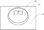
- FIG. 1is a schematic structural diagram of a polarized lens provided in Embodiment 1 of the present application.
- FIG. 3is a schematic cross-sectional structural diagram of the lighting device provided in Embodiment 1 of the present application.
- FIG. 4is a schematic top-view structural diagram of the lighting device provided in Embodiment 1 of the present application.
- FIG. 5is a longitudinal sectional view of a first longitudinal section of the lighting device provided in Embodiment 1 of the present application;
- FIG. 6is a longitudinal sectional view of a second longitudinal section of the lighting device provided in Embodiment 1 of the present application;
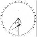
- FIG. 7is a light distribution curve diagram of a polarized lens when the light-emitting unit is located at the first position according to Embodiment 1 of the present application;
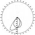
- FIG. 9is a light distribution curve diagram of the polarized lens when the light-emitting unit is located at the third position according to Embodiment 1 of the present application;
- FIG. 10is a light distribution curve diagram of the polarized lens when the light-emitting unit is located at the fourth position according to Embodiment 1 of the present application;
- FIG. 11is a light distribution curve diagram of the polarized lens when the light-emitting unit is located at the fourth position according to Embodiment 1 of the present application;
- FIG. 12is a schematic structural diagram of the lighting device provided in Embodiment 2 of the present application.
- FIG. 13is a schematic top-view structural diagram of the lighting device provided in Embodiment 2 of the present application.
- 17is a light distribution curve diagram of the polarized lens when the light-emitting unit is located at the fourth position according to Embodiment 2 of the present application;
- FIG. 18is a light distribution curve diagram of the polarized lens when the light emitting unit is located at the fifth position according to Embodiment 2 of the present application.
- Polarized lens-20light-incident surface-21;
- a groove 231is provided on one side of the lens body 23, and the light incident surface 21 is the bottom surface of the groove for collecting light sources.
- the light incident surface 21is a symmetrical ellipsoid crown, and after the light emitted by the light source passes through the light incident surface 21 and enters the lens body 23, the angle of the light is not deflected.
- the light incident surface 21may also be a symmetrical spherical cap or an eccentric spherical surface.
- the other side of the lens body 23is provided with a protrusion 232 , and the light-emitting surface 22 is the surface of the protrusion 232 , and is disposed opposite to the light-incident surface 22 for emitting light sources.
- the light emitting surface 22is an eccentric spherical surface. The light emitted by the light source passes through the light incident surface 21 and enters the lens body 23 and then passes through the light emitting surface 22. The angle of the light is deflected and deflected to the same side.
- connection platform 24is positioned around the lens body 23, is connected to the edge of the polarized lens 20, connects the light incident surface 21 and the light exit surface 22, and the light incident surface 21 and the light exit surface 22 of the polarized lens 20 and the connection platform 24 are an integrated structure.
- the projection of the polarizing lens 20 on the substrate 10is an axisymmetric figure, the axis of symmetry of the projection of the polarizing lens 20 on the substrate 10 is defined as the central axis of the polarizing lens 20, and the first longitudinal section of the polarizing lens 20 is defined as passing through the central axis and perpendicular to the axis. In the plane of the substrate, the second longitudinal section of the polarizing lens 20 is defined as being perpendicular to the central axis and perpendicular to the plane of the substrate.
- the projection of the light-emitting surface 22 on the reference surfaceis an axisymmetric figure, and the intersection of the symmetry axis of the axisymmetric figure and the projection of the light-emitting surface 22 on the reference surface is defined.
- the projection of the light-incident surface 21 on the reference surfaceis an axisymmetric figure, and the intersection of the symmetry axis of the axisymmetric figure and the projection of the light-incident surface 21 on the reference surface is defined as the projection of the light-incident surface.
- the midpoint of the projected central axis of the light incident surface 21is separated from the midpoint of the projected central axis of the light exit surface 22 .
- a plane passing through the projected central axis segment of the light exit surface 22 and perpendicular to the reference planeis defined as the first longitudinal section
- a plane perpendicular to the reference plane and perpendicular to the first longitudinal sectionis defined as the second longitudinal section.
- the intersection of the light-emitting surface 22 and the first longitudinal sectionis an eccentric curve
- the intersection of the light-incident surface 21 and the first longitudinal sectionis an arc
- the intersection of the light-emitting surface 22 and the second longitudinal sectionis semicircular or arcuate.
- the intersection line of the light-emitting surface 22 and the first longitudinal sectionis an eccentric curve.
- the projection of the point with the smallest radius of curvature on the eccentric curve on the reference surfaceis the distance between the projection of the light-emitting surface 22 and an end point of the central axis of the projection of the light-emitting surface 22, and the projection of the light-emitting surface 22.
- the ratio of the lengths of the axis segmentsis 0.2-0.4.
- the projected area of the light incident surface 21 on the reference surfaceis smaller than the projected area of the light exit surface 22 on the reference surface, and part or all of the projection of the light incident surface 21 on the reference surface is located within the projection of the light exit surface 22 on the reference surface 2.
- An embodiment of the present applicationfurther provides an illumination device 100 .
- the illumination device 100includes a substrate 10 , a polarizing lens 20 , and a light-emitting unit 30 .
- the light-incident surface 21 and the substrate 10enclose a cavity 233 .
- the light-emitting unit 30is arranged in the cavity 233 and is mounted on the substrate 10 . There is a gap between the light-emitting unit 30 and the light-incident surface 21 . light distribution.
- FIG. 5is a longitudinal cross-sectional view of the first longitudinal section of the polarizing lens 20 .
- the light emitting unit 30is located on the symmetry axis of the projection of the light incident surface 21 of the polarizing lens 20 on the reference surface.
- the intersection of the connecting platform and the first longitudinal sectionforms a first platform 241 and a second platform 242 .
- the projection of the light incident surface 21 on the substrate 10partially overlaps with the projection of the light emitting surface 22 on the substrate 10 . It can be seen from FIG.
- the projection of the light incident surface 21 on the substrate 10Covers the projection of the light-emitting surface 22 on the substrate 10 ; on the side close to the first platform 241 , the projection of the light-emitting surface 22 on the substrate 10 covers the projection of the light-incident surface 21 on the substrate 10 .
- the ratio of the distance between the center point of the light-emitting unit 30 and an end point of the projected central axis segment of the light incident surface 21 and the length of the projected central axis segment of the light incident surface 21is 0.2-0.5.
- FIG. 6is a longitudinal cross-sectional view of the second longitudinal section of the polarizing lens 20 .
- the intersection line of the light incident surface 21 and the second longitudinal sectionis an arcuate shape, and the intersection line of the light exit surface 22 and the second longitudinal section is an arcuate shape.
- the intersection line of the light incident surface 21 and the second longitudinal sectionis a semicircle.
- the refracted rays of the light emitted from the light emitting unit after passing through the polarizing lens 20 in the second longitudinal section of the polarizing lens 20are close to the central axis of the light incident surface.
- the light emitting unit 30has a first position, a second position, a third position, a fourth position and a fifth position on the axis of symmetry of the projection of the polarizing lens 20 on the substrate 10 .
- the light emitting unit 30is closer to the second platform 242 , the light distribution angle of the polarizing lens 20 is smaller, and when the light emitting unit 30 is farther away from the second platform 242 , the light distribution angle of the polarizing lens 20 is smaller.
- the distance between the first platform 241 and the second platform 242is 3.6 mm
- the distance between the first position of the light-emitting unit 30 and the second platform 240is 0.3 mm
- the polarized lightis
- the light distribution angle of the lens to the light-emitting unit 30 in the first longitudinal sectionis 25 degrees
- the light distribution angle of the polarizing lens to the light-emitting unit 30 in the second longitudinal sectionis 90 degrees
- the maximum light intensity of the first longitudinal sectiondeviates from the light incident surface 21 45 degrees of the central axis.
- the minimum distance between the first position of the light-emitting unit 30 and the second platform 240is 0.3mm.
- the distance between the third position of the light-emitting unit 30 and the second platform 240is 1.4 mm, and the light distribution angle of the polarizing lens to the light-emitting unit 30 in the first longitudinal section is 40 degrees , the light distribution angle of the polarizing lens to the light-emitting unit 30 in the second longitudinal section is 90 degrees, and the maximum light intensity of the first longitudinal section is deviated from the central axis of the light incident surface 21 by 40 degrees.
- the distance between the fourth position of the light-emitting unit 30 and the second platform 240is 2 mm
- the light distribution angle of the polarizing lens to the light-emitting unit 30 in the first longitudinal sectionis 50 degrees
- the light distribution angle of the polarizing lens to the light emitting unit 30 in the second longitudinal sectionis 90 degrees
- the maximum light intensity of the first longitudinal sectionis deviated from the central axis of the light incident surface 21 by 36 degrees.
- the light distribution angle of the polarizing lens to the light-emitting unit 30 in the first longitudinal sectionis 60 degrees
- the light distribution angle of the polarizing lens to the light emitting unit 30 in the second longitudinal sectionis 90 degrees
- the maximum light intensity of the first longitudinal sectionis deviated from the central axis of the light incident surface 21 by 30 degrees.
- the light-emitting unit 30is movably mounted on the substrate 10, the substrate 10 is provided with a slide rail, the light-emitting unit 30 can move in the slide rail, and the moving path of the light-emitting unit is the symmetry of the projection on the reference plane of the polarizing lens axis.
- the optical modulecan be used in various occasions.
- the optical modulefurther includes a driving power source and a lampshade (not shown in the figure), the driving power source is arranged on the substrate, and the driving power source is electrically connected with the light-emitting unit to provide power for the light-emitting unit; the lampshade is arranged on the substrate and cover the light-emitting unit and the lens, to protect the light-emitting unit and the lens.
- the optical module in this embodimentwill solve this technical problem.
- the optical module 100is arranged on the lamp pole of the street lamp. Since the polarized lens has different angles of light distribution in the first longitudinal section and the second longitudinal section, respectively, Therefore, the first longitudinal section is set parallel to the road direction, and the second longitudinal section is perpendicular to the road direction.
- the low polerequires a large illumination area, a large angle light distribution is required, and the position of the light emitting unit is set close to the first platform; when the high pole requires key lighting, a small angle light distribution is required, and the light emitting unit is set close to the first platform.
- For the second platformthere is no need to adjust the elevation angle of the lamps to prevent the light from entering the human eye and causing uncomfortable glare.
- the lighting device in this embodimentis substantially the same as the corresponding structure in Embodiment 1, and the same structure can refer to the corresponding description in Embodiment 1, and details are not repeated here.
- the light-emitting unituses two 3030 lamp beads, as shown in Figure 12 and Figure 13, the diameter of the 3030 lamp bead is 3mm, and the two 3030 lamp beads in the light-emitting unit The distance of the beads is 1mm, and a total of 64 3030 lamp beads are arranged on the substrate 10.
- the distance between the first platform 241 and the second platform 242is 4.6 mm
- the distance between the first position of the light-emitting unit 30 and the second platform 242is 0.8 mm
- the polarizing lensis at
- the light distribution angle of the first longitudinal section to the light-emitting unit 30is 25 degrees
- the light distribution angle of the polarizing lens to the light-emitting unit 30 in the second longitudinal sectionis 90 degrees
- the maximum light intensity of the first longitudinal sectionis deviated from the center of the light incident surface 21 Axis 42 degrees.
- the distance between the second position of the light-emitting unit 30 and the second platform 240is 1 mm
- the light distribution angle of the polarizing lens to the light-emitting unit 30 in the first longitudinal sectionis 30 degrees
- the light distribution angle of the polarizing lens to the light-emitting unit 30 in the second longitudinal sectionis 90 degrees
- the maximum light intensity of the first longitudinal sectionis deviated from the central axis of the light incident surface 21 by 39 degrees.
- the distance between the third position of the light-emitting unit 30 and the second platform 240is 1.6 mm
- the light distribution angle of the polarizing lens to the light-emitting unit 30 in the first longitudinal sectionis 40 degrees
- the light distribution angle of the polarizing lens to the light-emitting unit 30 in the second longitudinal sectionis 90 degrees
- the maximum light intensity of the first longitudinal sectionis deviated from the central axis of the light incident surface 21 by 36 degrees.
- the distance between the fourth position of the light-emitting unit 30 and the second platform 240is 2 mm
- the light distribution angle of the polarizing lens to the light-emitting unit 30 in the first longitudinal sectionis 50 degrees
- the light distribution angle of the polarizing lens to the light emitting unit 30 in the second longitudinal sectionis 90 degrees
- the maximum light intensity of the first longitudinal sectionis deviated from the central axis of the light incident surface 21 by 36 degrees.
- the distance between the fifth position of the light-emitting unit 30 and the second platform 240is 3 mm
- the light distribution angle of the polarizing lens to the light-emitting unit 30 in the first longitudinal sectionis 60 degrees
- the light distribution angle of the polarizing lens to the light emitting unit 30 in the second longitudinal sectionis 90 degrees
- the maximum light intensity of the first longitudinal sectionis deviated from the central axis of the light incident surface 21 by 30 degrees.
- the optical modulecan be used in various occasions.
Landscapes
- Engineering & Computer Science (AREA)
- General Engineering & Computer Science (AREA)
- Non-Portable Lighting Devices Or Systems Thereof (AREA)
Abstract
Description
Translated fromChinese本申请要求了申请日为2020年12月31日,申请号为202011623395.2,发明名称为“一种光学模组及照明装置”的中国专利申请的优先权,该项专利申请的全部内容通过引用结合在本申请中。This application claims the priority of the Chinese patent application whose filing date is December 31, 2020, the application number is 202011623395.2, and the invention name is "an optical module and lighting device", the entire contents of which are incorporated by reference in this application.
本申请涉及照明技术领域,尤其地涉及一种光学模组及照明装置。The present application relates to the field of lighting technology, and in particular, to an optical module and a lighting device.
投光灯又称聚光灯、投射灯,是一种将光源光线汇聚投向指定方向实现区域化照明的灯具。常用于广场照明、大面积作业照明、历史建筑群外墙照明、室内局部照明等场景。Spotlights, also known as spotlights and spotlights, are lamps that gather light from a light source and project them in a designated direction to achieve regional lighting. Commonly used in square lighting, large-area operation lighting, exterior wall lighting of historical buildings, indoor local lighting and other scenes.
投光灯大多采用透镜结合LED光源的形式,实现光学模组的整体照明作业。目前市场上光学模组的配光仍属于对称式的配光,即所采用的二次光学透镜,其配光曲面在X-X剖面及Y-Y剖面分别是对称配光的,即出射光线按照透镜的光轴左右和上下分别对称配光,形成一个左右对称和上下对称的长方形光斑。有一小部分光学模组产品做到了非对称配光(即所谓的偏光),其配光曲线为蝙蝠翼形状,但是由于偏光透镜配光计算及建模比较困难,大部分偏光透镜的偏光角度只能做到30度。Most of the floodlights use the form of lens combined with LED light source to realize the overall lighting operation of the optical module. At present, the light distribution of optical modules on the market still belongs to the symmetrical light distribution, that is, the secondary optical lens used has a symmetrical light distribution in the X-X section and the Y-Y section, that is, the outgoing light is in accordance with the light of the lens. The left and right and top and bottom of the axis are symmetrically distributed, forming a rectangular light spot with left and right symmetry and up and down symmetry. A small number of optical module products have achieved asymmetric light distribution (so-called polarized light), and their light distribution curve is in the shape of a bat wing. However, due to the difficulty in calculating and modeling the light distribution of polarized lenses Can do 30 degrees.
因此,确有必要来开发一种新型的光学模组,以克服现有技术的缺陷。Therefore, it is indeed necessary to develop a new type of optical module to overcome the defects of the prior art.
发明内容SUMMARY OF THE INVENTION
本申请的一个目的是提供一种光学模组,其能够解决已知技术中偏光投光灯的偏光角度较小的问题。An object of the present application is to provide an optical module, which can solve the problem that the polarization angle of the polarized flood light in the prior art is small.
为实现上述目的,本申请提供一种光学模组,包括一偏光透镜,所述偏光透镜包括:透镜体,其一侧设有凹槽,其另一侧设有一凸起;入光面,其为所述凹槽的底面,所述入光面为对称的球冠或椭球冠或偏心球面;以及出光面,其为所述凸起的表面,与所述入光面相对设置,所述出光面为偏心球面。In order to achieve the above purpose, the present application provides an optical module, including a polarized lens, the polarized lens includes: a lens body, one side of which is provided with a groove, and the other side is provided with a protrusion; is the bottom surface of the groove, the light incident surface is a symmetrical spherical cap or ellipsoid cap or an eccentric spherical surface; and the light exit surface, which is the convex surface, is arranged opposite the light incident surface, the The light-emitting surface is an eccentric spherical surface.
进一步的,在其他实施方式中,其中以所述凹槽的槽口所处平面为参照面,所述出光面在所述参照面上的投影为轴对称图形,定义该轴对称图形的对称轴与所述出光面在所述参照面上的投影的交点为出光面投影中轴线段,定义经过所述出光面投影中轴线段且垂直于所述参照面的平面为第一纵向截面,所述出光面与所述第一纵向截面的交线为一偏心曲线。Further, in other embodiments, the plane where the notch of the groove is located is the reference plane, the projection of the light emitting surface on the reference plane is an axisymmetric figure, and the symmetry axis of the axisymmetric figure is defined. The intersection point with the projection of the light-emitting surface on the reference surface is the projection center axis segment of the light-emitting surface, and a plane passing through the projection center-axis segment of the light-emitting surface and perpendicular to the reference surface is defined as the first longitudinal section. The intersection line of the light-emitting surface and the first longitudinal section is an eccentric curve.
进一步的,在其他实施方式中,其中所述偏心曲线上曲率半径最小的一点在所述参照面上的投影与所述出光面投影中轴线段的一端点的距离,与所述出光面投影中轴线段的长度的比值为0.2-0.4。Further, in other embodiments, the distance between the projection of the point with the smallest radius of curvature on the eccentric curve on the reference surface and an end point of the axis segment in the projection of the light-emitting surface is the same as that in the projection of the light-emitting surface. The ratio of the lengths of the axis segments is 0.2-0.4.
进一步的,在其他实施方式中,其中所述入光面在所述参照面上的投影为轴对称图形,定义该轴对称图形的对称轴与所述入光面在所述参照面上的投影的交点为入光面投影中轴线段,所述入光面投影中轴线段的中点与所述出光面投影中轴线的中点相离。Further, in other embodiments, the projection of the light incident surface on the reference surface is an axisymmetric figure, and the symmetry axis of the axisymmetric figure and the projection of the light incident surface on the reference surface are defined. The intersection point is the projected central axis segment of the light incident surface, and the midpoint of the projected central axis segment of the light incident surface is separated from the midpoint of the projected central axis of the light exit surface.
进一步的,在其他实施方式中,其中所述入光面与所述第一纵向截面的交线为一弧线。Further, in other embodiments, the intersection line of the light incident surface and the first longitudinal section is an arc.
进一步的,在其他实施方式中,其中所述入光面在所述参照面上的投影的面积小于所述出光面在所述参照面上的投影面积。Further, in other embodiments, the projected area of the light incident surface on the reference surface is smaller than the projected area of the light exit surface on the reference surface.
进一步的,在其他实施方式中,其中还包括连接平台,连接至所述偏光透镜的边缘处。Further, in other embodiments, a connecting platform is also included, which is connected to the edge of the polarizing lens.
进一步的,在其他实施方式中,其中所述偏光透镜与所述连接平台为一体化结构。Further, in other embodiments, the polarizing lens and the connecting platform are an integrated structure.
进一步的,在其他实施方式中,其中定义垂直于所述参照面的平面且垂直于所述第一纵向截面的平面为第二纵向截面;所述出光面与所述第二纵向截面的交线为半圆形或弓形。Further, in other embodiments, a plane perpendicular to the reference plane and a plane perpendicular to the first longitudinal section is defined as a second longitudinal section; the intersection of the light exit surface and the second longitudinal section It is semicircular or arcuate.
为实现上述目的,本申请还提供一种照明装置,包括本申请涉及的所述光学模组。In order to achieve the above purpose, the present application further provides an illumination device including the optical module involved in the present application.
进一步的,在其他实施方式中,其中,包括基板,所述光学模组被安装至所述基板,所述光学模组的入光面与所述基板围成一腔体;所述基板的平面与所述凹槽的槽口所处平面相平行。Further, in other embodiments, a substrate is included, the optical module is mounted on the substrate, the light incident surface of the optical module and the substrate form a cavity; the plane of the substrate parallel to the plane where the notch of the groove is located.
进一步的,在其他实施方式中,其中,包括发光单元,设于所述腔体内,且安装至所述基板。Further, in other embodiments, a light-emitting unit is included, disposed in the cavity, and mounted on the substrate.
进一步的,在其他实施方式中,其中,所述发光单元位于所述入光面在所述参照面上的投影的对称轴上。Further, in other embodiments, the light emitting unit is located on the axis of symmetry of the projection of the light incident surface on the reference surface.
进一步的,在其他实施方式中,其中,所述发光单元中心点与入光面投影中轴线段的一端点的距离,与所述入光面投影中轴线段的长度的比值为0.2-0.5。Further, in other embodiments, the ratio of the distance between the center point of the light-emitting unit and an end point of the projected central axis segment of the light incident surface and the length of the projected central axis segment of the light incident surface is 0.2-0.5.
进一步的,在其他实施方式中,其中,所述发光单元在所述基板上具有第一位置和第二位置,所述发光单元在所述第一位置时所述偏光透镜的配光角度小于所述发光单元在所述第二位置时所述偏光透镜的配光角度。Further, in other embodiments, the light-emitting unit has a first position and a second position on the substrate, and when the light-emitting unit is at the first position, the light distribution angle of the polarizing lens is smaller than that of the light-emitting unit. The light distribution angle of the polarizing lens when the light emitting unit is in the second position.
相对于已知技术,本申请的有益效果在于:本申请提供一种光学模组及照明装置,本申请提供的偏光透镜的偏光角度能做到60度,大大提高了偏光角度;另一方面,根据配光角度需要,调整发光单元和偏光透镜的相对位置,实现偏光透镜对发光单元配光角度的调节,使光学模组通用于各种场合使用。Compared with the known technology, the beneficial effects of the present application are as follows: the present application provides an optical module and an illuminating device, and the polarization angle of the polarizing lens provided by the present application can reach 60 degrees, which greatly improves the polarization angle; on the other hand, Adjust the relative position of the light-emitting unit and the polarizing lens according to the needs of the light distribution angle, so as to realize the adjustment of the light distribution angle of the light-emitting unit by the polarizing lens, so that the optical module can be used in various occasions.
下面结合附图,通过对本申请的具体实施方式详细描述,将使本申请的技术方案及其它有益效果显而易见。The technical solutions and other beneficial effects of the present application will be apparent through the detailed description of the specific embodiments of the present application in conjunction with the accompanying drawings.
图1为本申请实施例1提供的偏光透镜的结构示意图;1 is a schematic structural diagram of a polarized lens provided in Embodiment 1 of the present application;
图2为本申请实施例1提供的照明装置的结构示意图;2 is a schematic structural diagram of the lighting device provided in Embodiment 1 of the present application;
图3为本申请实施例1提供的照明装置的剖视结构示意图;3 is a schematic cross-sectional structural diagram of the lighting device provided in Embodiment 1 of the present application;
图4为本申请实施例1提供的照明装置的俯视结构示意图;FIG. 4 is a schematic top-view structural diagram of the lighting device provided in Embodiment 1 of the present application;
图5为本申请实施例1提供的照明装置的第一纵向截面的纵向剖视图;5 is a longitudinal sectional view of a first longitudinal section of the lighting device provided in Embodiment 1 of the present application;
图6为本申请实施例1提供的照明装置的第二纵向截面的纵向剖视图;6 is a longitudinal sectional view of a second longitudinal section of the lighting device provided in Embodiment 1 of the present application;
图7为本申请实施例1提供的当发光单元位于第一位置时偏光透镜的配光曲线图;7 is a light distribution curve diagram of a polarized lens when the light-emitting unit is located at the first position according to Embodiment 1 of the present application;
图8为本申请实施例1提供的当发光单元位于第二位置时偏光透镜的配光曲线图;8 is a light distribution curve diagram of the polarized lens when the light-emitting unit is located at the second position according to Embodiment 1 of the present application;
图9为本申请实施例1提供的当发光单元位于第三位置时偏光透镜的配光曲线图;9 is a light distribution curve diagram of the polarized lens when the light-emitting unit is located at the third position according to Embodiment 1 of the present application;
图10为本申请实施例1提供的当发光单元位于第四位置时偏光透镜的配光曲线图;10 is a light distribution curve diagram of the polarized lens when the light-emitting unit is located at the fourth position according to Embodiment 1 of the present application;
图11为本申请实施例1提供的当发光单元位于第四位置时偏光透镜的配光曲线图;11 is a light distribution curve diagram of the polarized lens when the light-emitting unit is located at the fourth position according to Embodiment 1 of the present application;
图12为本申请实施例2提供的照明装置的结构示意图;12 is a schematic structural diagram of the lighting device provided in Embodiment 2 of the present application;
图13为本申请实施例2提供的照明装置的俯视结构示意图;13 is a schematic top-view structural diagram of the lighting device provided in Embodiment 2 of the present application;
图14为本申请实施例2提供的当发光单元位于第一位置时偏光透镜的配光曲线图;14 is a light distribution curve diagram of a polarized lens when the light-emitting unit is located at the first position according to Embodiment 2 of the present application;
图15为本申请实施例2提供的当发光单元位于第二位置时偏光透镜的配光曲线图;15 is a light distribution curve diagram of the polarized lens when the light-emitting unit is located at the second position according to Embodiment 2 of the present application;
图16为本申请实施例2提供的当发光单元位于第三位置时偏光透镜的配光曲线图;16 is a light distribution curve diagram of the polarized lens when the light-emitting unit is located at the third position according to Embodiment 2 of the present application;
图17为本申请实施例2提供的当发光单元位于第四位置时偏光透镜的配光曲线图;17 is a light distribution curve diagram of the polarized lens when the light-emitting unit is located at the fourth position according to Embodiment 2 of the present application;
图18为本申请实施例2提供的当发光单元位于第五位置时偏光透镜的配光曲线图。FIG. 18 is a light distribution curve diagram of the polarized lens when the light emitting unit is located at the fifth position according to Embodiment 2 of the present application.
附图说明:Description of drawings:
照明装置-100; 基板-10;Lighting device-100; Substrate-10;
偏光透镜-20; 入光面-21;Polarized lens-20; light-incident surface-21;
发光单元-30; 出光面-22;Light-emitting unit-30; Light-emitting surface-22;
透镜体-23;lens body-23;
连接平台-24; 凹槽-231;connection platform-24; groove-231;
凸起-232; 腔体-233;Bump-232; Cavity-233;
第一平台-241; 第二平台-242。The first platform-241; The second platform-242.
下面将结合本申请实施例中的附图,对本申请实施例中的技术方案进行清楚、完整地描述。显然,所描述的实施例仅仅是本申请一部分实施例,而不是全部的实施例。基于本申请中的实施例,本领域技术人员在没有作出创造性劳动前提下所获得的所有其他实施例,都属于本申请保护的范围。The technical solutions in the embodiments of the present application will be clearly and completely described below with reference to the accompanying drawings in the embodiments of the present application. Obviously, the described embodiments are only a part of the embodiments of the present application, but not all of the embodiments. Based on the embodiments in the present application, all other embodiments obtained by those skilled in the art without creative work fall within the protection scope of the present application.
实施例1Example 1
本申请实施例提供一种光学模组,包括偏光透镜20,如图1所示,偏光透镜20包括一入光面21、一出光面22、透镜体23和连接平台24。An embodiment of the present application provides an optical module including a
透镜体23一侧设有凹槽231,入光面21为凹槽的底面,用于收集光源。在本实施例中,入光面21为对称的椭球冠,光源发出的光线经过入光面21进入透镜体23后,光线的角度不发生偏转。在其他实施例中,入光面21也可以为对称的球冠或偏心球面。A
透镜体23的另一侧设有一凸起232,出光面22为凸起232的表面,与入光面22相对设置,用于发射光源。在本实施例中,出光面22为偏心球面,光源发出的光线经过入光面21进入透镜体23再经过出光面22后,光线的角度发生偏转,并向同一侧偏转。The other side of the
连接平台24位于透镜体23的四周,连接至偏光透镜20的边缘处,连接入光面21和出 光面22,偏光透镜20的入光面21和出光面22与连接平台24为一体化结构。The
偏光透镜20在基板10上的投影为轴对称图形,定义偏光透镜20在基板10上的投影的对称轴为偏光透镜20的中轴线,定义偏光透镜20的第一纵向截面为经过中轴线且垂直于基板的平面,定义偏光透镜20的第二纵向截面为垂直于中轴线且垂直于基板的平面。The projection of the
以凹槽231的槽口所处平面为参照面,出光面22在参照面上的投影为轴对称图形,定义该轴对称图形的对称轴与出光面22在所述参照面上的投影的交点为出光面投影中轴线段,入光面21在参照面上的投影为轴对称图形,定义该轴对称图形的对称轴与入光面21在参照面上的投影的交点为入光面投影中轴线段,入光面21投影中轴线段的中点与出光面22投影中轴线的中点相离。Taking the plane where the notch of the
定义经过出光面22投影中轴线段且垂直于参照面的平面为第一纵向截面,定义垂直于参照面的平面且垂直于第一纵向截面的平面为第二纵向截面。出光面22与第一纵向截面的交线为一偏心曲线,入光面21与第一纵向的交线为一弧线;出光面22与第二纵向截面的交线为半圆形或弓形。A plane passing through the projected central axis segment of the
出光面22与第一纵向截面的交线为一偏心曲线,偏心曲线上曲率半径最小的一点在参照面上的投影与出光面22投影中轴线段的一端点的距离,与出光面22投影中轴线段的长度的比值为0.2-0.4。The intersection line of the light-emitting
入光面21在参照面上的投影的面积小于出光面22在参照面上的投影面积,入光面21在参照面上的投影的部分或全部位于出光面22在2参照面上的投影内。The projected area of the
本申请实施例还提供一种照明装置100,如图2和图3所示,照明装置100包括基板10、偏光透镜20、发光单元30。An embodiment of the present application further provides an
入光面21与基板10围成一腔体233,发光单元30设于腔体233内,安装至基板10,发光单元30与入光面21之间具有间隙,偏光透镜20对发光单元30发出的光线进行配光。The light-
基板10的平面与凹槽231的槽口所处平面相平行,连接平台24的底面与基板10相接。The plane of the
请参阅图5,图5为偏光透镜20的第一纵向截面的纵向剖视图,发光单元30位于偏光透镜20的入光面21在参照面上的投影的对称轴上。连接平台与第一纵向截面的交线形成第一平台241和第二平台242。入光面21在基板10上的投影与出光面22在基板10上的投影部分交叠,由图5中可知,在靠近第二平台242的一侧,入光面21在基板10上的投影覆盖出光面22在基板10上的投影;在靠近第一平台241的一侧,出光面22在基板10上的投影覆盖入光面21在基板10上的投影。Please refer to FIG. 5 , which is a longitudinal cross-sectional view of the first longitudinal section of the
发光单元30中心点与入光面21投影中轴线段的一端点的距离,与入光面21投影中轴线段的长度的比值为0.2-0.5。The ratio of the distance between the center point of the light-emitting
在其他实施例中,入光面21为对称的球冠时,入光面21与第一纵向截面的的交线为半圆形。In other embodiments, when the
以入光面21的中心轴与基板10相交的点为坐标原点,以入光面21的中心轴为z轴, 以偏光透镜20在基板10上的投影的对称轴为x轴,建立三维坐标系,y轴分别垂直于x轴及z轴。坐标原点朝向第一平台241的方向为x轴的负方向。坐标原点朝向第二平台242的方向为x轴的正方向,偏心曲面在该坐标上的公式为:Taking the point where the central axis of the
y=-2×10-10x6-8×10-9x5+7×10-7x4+2×10-5x3-0.0078x2-0.3006x+84.923y = -2×10-10 x6 -8 x 10-9 x5 +7 x 10-7 x4 +2 x 10-5 x3 -0.0078x2 -0.3006x+84.923
从发光单元出射的光在偏光透镜的第一纵向截面经过偏光透镜后的折射光线偏离入光面的中心轴,偏向第一平台241的方向。The refracted rays of the light emitted from the light emitting unit after passing through the polarizing lens in the first longitudinal section of the polarizing lens are deviated from the central axis of the light incident surface and are deviated towards the direction of the
请参阅图6,图6为偏光透镜20的第二纵向截面的纵向剖视图。入光面21与第二纵向截面的交线为一弓形,出光面22与第二纵向截面的交线为一弓形。在其他实施例中,入光面21为对称的球冠时,入光面21与第二纵向截面的交线为半圆形。Please refer to FIG. 6 , which is a longitudinal cross-sectional view of the second longitudinal section of the
从发光单元出射的光在偏光透镜20的第二纵向截面经过偏光透镜20后的折射光线靠近入光面的中心轴。The refracted rays of the light emitted from the light emitting unit after passing through the
如图2和图4所示,在本实施例中,发光单元采用一个5050灯珠,5050灯珠的直径为5mm,在基板10上总共排布32颗5050灯珠。As shown in FIG. 2 and FIG. 4 , in this embodiment, the light-emitting unit adopts one 5050 lamp bead, the diameter of the 5050 lamp bead is 5 mm, and a total of 32 5050 lamp beads are arranged on the
发光单元30在偏光透镜20在基板10上的投影的对称轴上具有第一位置、第二位置、第三位置、第四位置和第五位置。当发光单元30越靠近第二平台242,偏光透镜20的配光角度越小,当发光单元30越远离第二平台242时,偏光透镜20的配光角度越小。The
如图7所示,在本实施例中,第一平台241和第二平台242之间的距离为3.6mm,发光单元30的第一位置与第二平台240之间的距离为0.3mm,偏光透镜在第一纵向截面对发光单元30的配光角度为25度,偏光透镜在第二纵向截面对发光单元30的配光角度为90度,第一纵向截的最大光强偏离入光面21的中心轴45度。As shown in FIG. 7 , in this embodiment, the distance between the
发光单元30的发光中心点距离第二平台240的长度小于0.3mm时,可能会产生干涉,因此在本实施例中,设置发光单元30的第一位置与第二平台240之间的最小距离为0.3mm。When the length of the light-emitting center point of the light-emitting
如图8所示,在本实施例中,发光单元30的第二位置与第二平台240之间的距离为0.8mm,偏光透镜在第一纵向截面对发光单元30的配光角度为30度,偏光透镜在第二纵向截面对发光单元30的配光角度为90度,第一纵向截的最大光强偏离入光面21的中心轴42度。As shown in FIG. 8 , in this embodiment, the distance between the second position of the light-emitting
如图9所示,在本实施例中,发光单元30的第三位置与第二平台240之间的距离为1.4mm,偏光透镜在第一纵向截面对发光单元30的配光角度为40度,偏光透镜在第二纵向截面对发光单元30的配光角度为90度,第一纵向截的最大光强偏离入光面21的中心轴40度。As shown in FIG. 9 , in this embodiment, the distance between the third position of the light-emitting
如图10所示,在本实施例中,发光单元30的第四位置与第二平台240之间的距离为2mm,偏光透镜在第一纵向截面对发光单元30的配光角度为50度,偏光透镜在第二纵向截面对发光单元30的配光角度为90度,第一纵向截的最大光强偏离入光面21的中心轴36度。As shown in FIG. 10 , in this embodiment, the distance between the fourth position of the light-emitting
如图11所示,在本实施例中,发光单元30的第五位置与第二平台240之间的距离为3mm时,偏光透镜在第一纵向截面对发光单元30的配光角度为60度,偏光透镜在第二纵向截面对发光单元30的配光角度为90度,第一纵向截的最大光强偏离入光面21的中心轴30度。As shown in FIG. 11 , in this embodiment, when the distance between the fifth position of the light-emitting
定义发光单元30的发光中心点距离第二平台240的长度为a,偏光透镜在第二纵向截面对发光单元30的配光角度为b,则b=15.6a+18.5。The length of the light-emitting center point of the light-emitting
在其他实施方式中,发光单元30可移动式安装至基板10上,基板10上设置有滑轨,发光单元30能够在滑轨中移动,发光单元的移动路径为偏光透镜参照面上的投影的对称轴。In other embodiments, the light-emitting
根据配光角度需要,通过调整发光单元和偏光透镜的相对位置,实现偏光透镜对发光单元配光角度的调节,使光学模组通用于各种场合使用。According to the needs of the light distribution angle, by adjusting the relative position of the light emitting unit and the polarizing lens, the adjustment of the light distribution angle of the light emitting unit by the polarizing lens is realized, so that the optical module can be used in various occasions.
在本实施例中,光学模组还包括驱动电源和灯罩(图未示),驱动电源设于基板上,且驱动电源与发光单元电性连接,用于为发光单元提供电源;灯罩设于基板上,且覆盖于发光单元和透镜的上方,用于保护发光单元和透镜。In this embodiment, the optical module further includes a driving power source and a lampshade (not shown in the figure), the driving power source is arranged on the substrate, and the driving power source is electrically connected with the light-emitting unit to provide power for the light-emitting unit; the lampshade is arranged on the substrate and cover the light-emitting unit and the lens, to protect the light-emitting unit and the lens.
本实施例中的光学模组可以应用于路灯,现有技术中的路灯由于其配光角度不可调,当低杆要求大照射面积时需要大角度配光的光学模组,高杆要求照明时需要小角度配光的光学模组,都是通过调整灯具的仰角来实现向前投射,但会有部分光线进入人眼形成不舒适眩光。The optical module in this embodiment can be applied to street lamps. Because the light distribution angle of the street lamps in the prior art is not adjustable, when a low pole requires a large irradiation area, an optical module with a large angle light distribution is required, and when a high pole requires lighting Optical modules that require small-angle light distribution all realize forward projection by adjusting the elevation angle of the lamps, but some light will enter the human eye to form uncomfortable glare.
而本实施例中的光学模组将会解决这个技术问题,将光学模组100设于路灯的灯杆上,由于偏光透镜在第一纵向截面及第二纵向截面分别有不同角度的配光,故将第一纵向截面设置为平行于道路方向,第二纵向截面垂直于道路方向。当低杆要求大照射面积时,需要大角度配光,此时设置发光单元的位置靠近第一平台;当高杆要求重点照明时,需要小角度配光,此时设置发光单元的位置靠近第二平台,不需要调整灯具的仰角,避免光线进入人眼形成不舒适眩光。The optical module in this embodiment will solve this technical problem. The
实施例2Example 2
本实施例中的照明装置与实施例1中的对应结构大致相同,其相同的结构可参照实施例1中的对应描述,此处不再赘述。其中两者的主要不同之处在于,在本实施例中,发光单元采用两个3030灯珠,如图12和图13所示,3030灯珠的直径为3mm,发光单元中的两个3030灯珠的距离为1mm,在基板上10总共排布64颗3030灯珠。The lighting device in this embodiment is substantially the same as the corresponding structure in Embodiment 1, and the same structure can refer to the corresponding description in Embodiment 1, and details are not repeated here. The main difference between the two is that in this embodiment, the light-emitting unit uses two 3030 lamp beads, as shown in Figure 12 and Figure 13, the diameter of the 3030 lamp bead is 3mm, and the two 3030 lamp beads in the light-emitting unit The distance of the beads is 1mm, and a total of 64 3030 lamp beads are arranged on the
如图14所示,在本实施例中,第一平台241与第二平台242的距离为4.6mm,发光单元30的第一位置与第二平台242之间的距离为0.8mm,偏光透镜在第一纵向截面对发光单元30的配光角度为25度,偏光透镜在第二纵向截面对发光单元30的配光角度为90度,第一纵向截的最大光强偏离入光面21的中心轴42度。As shown in FIG. 14 , in this embodiment, the distance between the
如图15所示,在本实施例中,发光单元30的第二位置与第二平台240之间的距离为1mm,偏光透镜在第一纵向截面对发光单元30的配光角度为30度,偏光透镜在第二纵向截面对发光单元30的配光角度为90度,第一纵向截的最大光强偏离入光面21的中心轴39 度。As shown in FIG. 15 , in this embodiment, the distance between the second position of the light-emitting
如图16所示,在本实施例中,发光单元30的第三位置与第二平台240之间的距离为1.6mm,偏光透镜在第一纵向截面对发光单元30的配光角度为40度,偏光透镜在第二纵向截面对发光单元30的配光角度为90度,第一纵向截的最大光强偏离入光面21的中心轴36度。As shown in FIG. 16 , in this embodiment, the distance between the third position of the light-emitting
如图17所示,在本实施例中,发光单元30的第四位置与第二平台240之间的距离为2mm,偏光透镜在第一纵向截面对发光单元30的配光角度为50度,偏光透镜在第二纵向截面对发光单元30的配光角度为90度,第一纵向截的最大光强偏离入光面21的中心轴36度。As shown in FIG. 17 , in this embodiment, the distance between the fourth position of the light-emitting
如图18所示,在本实施例中,发光单元30的第五位置与第二平台240之间的距离为3mm,偏光透镜在第一纵向截面对发光单元30的配光角度为60度,偏光透镜在第二纵向截面对发光单元30的配光角度为90度,第一纵向截的最大光强偏离入光面21的中心轴30度。As shown in FIG. 18 , in this embodiment, the distance between the fifth position of the light-emitting
根据配光角度需要,通过调整发光单元和偏光透镜的相对位置,实现偏光透镜对发光单元配光角度的调节,使光学模组通用于各种场合使用。According to the needs of the light distribution angle, by adjusting the relative position of the light emitting unit and the polarizing lens, the adjustment of the light distribution angle of the light emitting unit by the polarizing lens is realized, so that the optical module can be used in various occasions.
在上述实施例中,对各个实施例的描述都各有侧重,某个实施例中没有详述的部分,可以参见其他实施例的相关描述。In the above-mentioned embodiments, the description of each embodiment has its own emphasis. For parts that are not described in detail in a certain embodiment, reference may be made to the relevant descriptions of other embodiments.
以上对本申请实施例所提供的一种光学模组进行了详细介绍,本文中应用了具体个例对本申请的原理及实施方式进行了阐述,以上实施例的说明只是用于帮助理解本申请的技术方案及其核心思想;本领域的普通技术人员应当理解:其依然可以对前述各实施例所记载的技术方案进行修改,或者对其中部分技术特征进行等同替换;而这些修改或者替换,并不使相应技术方案的本质脱离本申请各实施例的技术方案的范围。An optical module provided by the embodiments of the present application has been introduced in detail above. The principles and implementations of the present application are described in this article by using specific examples. The descriptions of the above embodiments are only used to help understand the technology of the present application. scheme and its core idea; those of ordinary skill in the art should understand that: it is still possible to modify the technical solutions recorded in the foregoing embodiments, or to perform equivalent replacements for some of the technical features; and these modifications or replacements do not make The essence of the corresponding technical solutions deviates from the scope of the technical solutions of the embodiments of the present application.
Claims (16)
Translated fromChineseApplications Claiming Priority (2)
| Application Number | Priority Date | Filing Date | Title |
|---|---|---|---|
| CN202011623395.2 | 2020-12-31 | ||
| CN202011623395.2ACN112747288A (en) | 2020-12-31 | 2020-12-31 | Optical module and lighting device |
Publications (1)
| Publication Number | Publication Date |
|---|---|
| WO2022143411A1true WO2022143411A1 (en) | 2022-07-07 |
Family
ID=75650385
Family Applications (1)
| Application Number | Title | Priority Date | Filing Date |
|---|---|---|---|
| PCT/CN2021/140877CeasedWO2022143411A1 (en) | 2020-12-31 | 2021-12-23 | Optical module and lighting device |
Country Status (2)
| Country | Link |
|---|---|
| CN (1) | CN112747288A (en) |
| WO (1) | WO2022143411A1 (en) |
Families Citing this family (1)
| Publication number | Priority date | Publication date | Assignee | Title |
|---|---|---|---|---|
| CN112747288A (en)* | 2020-12-31 | 2021-05-04 | 欧普照明股份有限公司 | Optical module and lighting device |
Citations (7)
| Publication number | Priority date | Publication date | Assignee | Title |
|---|---|---|---|---|
| CN102054925A (en)* | 2009-10-29 | 2011-05-11 | 富准精密工业(深圳)有限公司 | Light emitting diode module |
| US20120307495A1 (en)* | 2011-06-06 | 2012-12-06 | Leotek Electronics Corporation | Optical lens and optical lens plate |
| CN103375769A (en)* | 2012-12-25 | 2013-10-30 | 深圳市斯派克光电科技有限公司 | Polarized lens unit and lens module for LED streetlights |
| CN105546476A (en)* | 2014-10-30 | 2016-05-04 | 全亿大科技(佛山)有限公司 | Optical lens and optical lens module thereof |
| CN105805696A (en)* | 2014-12-30 | 2016-07-27 | 全亿大科技(佛山)有限公司 | Lens, illuminating device provided with lens, and light guiding cover |
| CN112747288A (en)* | 2020-12-31 | 2021-05-04 | 欧普照明股份有限公司 | Optical module and lighting device |
| CN214840598U (en)* | 2020-12-31 | 2021-11-23 | 欧普照明股份有限公司 | Optical module and lighting device |
- 2020
- 2020-12-31CNCN202011623395.2Apatent/CN112747288A/ennot_activeWithdrawn
- 2021
- 2021-12-23WOPCT/CN2021/140877patent/WO2022143411A1/ennot_activeCeased
Patent Citations (7)
| Publication number | Priority date | Publication date | Assignee | Title |
|---|---|---|---|---|
| CN102054925A (en)* | 2009-10-29 | 2011-05-11 | 富准精密工业(深圳)有限公司 | Light emitting diode module |
| US20120307495A1 (en)* | 2011-06-06 | 2012-12-06 | Leotek Electronics Corporation | Optical lens and optical lens plate |
| CN103375769A (en)* | 2012-12-25 | 2013-10-30 | 深圳市斯派克光电科技有限公司 | Polarized lens unit and lens module for LED streetlights |
| CN105546476A (en)* | 2014-10-30 | 2016-05-04 | 全亿大科技(佛山)有限公司 | Optical lens and optical lens module thereof |
| CN105805696A (en)* | 2014-12-30 | 2016-07-27 | 全亿大科技(佛山)有限公司 | Lens, illuminating device provided with lens, and light guiding cover |
| CN112747288A (en)* | 2020-12-31 | 2021-05-04 | 欧普照明股份有限公司 | Optical module and lighting device |
| CN214840598U (en)* | 2020-12-31 | 2021-11-23 | 欧普照明股份有限公司 | Optical module and lighting device |
Also Published As
| Publication number | Publication date |
|---|---|
| CN112747288A (en) | 2021-05-04 |
Similar Documents
| Publication | Publication Date | Title |
|---|---|---|
| TWI626401B (en) | Lens for light emitting device | |
| CN102654268A (en) | LED (Light-Emitting Diode) lens device, LED lens device module and LED lamp device | |
| TWI506229B (en) | Light emitting apparatus and lens | |
| CN108302380B (en) | Lens type LED blackboard lamp | |
| WO2017054568A1 (en) | Led spotlight | |
| WO2012095006A1 (en) | Light distribution module design method for led lamps | |
| TWI471616B (en) | Lens module for light emitting diode light source | |
| WO2012028083A1 (en) | Method for designing uniform illumination reflector | |
| CN105042444A (en) | Blackboard LED lamp | |
| WO2022143411A1 (en) | Optical module and lighting device | |
| WO2021121318A1 (en) | Optical beam expander lens and lamp | |
| CN205424830U (en) | Spreadlight lens and have illumination lamps and lanterns of this spreadlight lens | |
| CN204986739U (en) | Blackboard LED lamp | |
| CN214840598U (en) | Optical module and lighting device | |
| TWI429953B (en) | Anti-glare lenses and table lamps with anti-glare lenses | |
| WO2020037950A1 (en) | Lens assembly capable of changing size of light spot | |
| CN217482671U (en) | Optical lens and lighting device | |
| CN207849093U (en) | A kind of narrow angle Windowsill lamp lens of light chopping and Windowsill lamp | |
| TW201428212A (en) | Zoom lens with multi-layers for illumination | |
| CN108150894A (en) | A kind of narrow angle Windowsill lamp lens of light chopping and Windowsill lamp | |
| TWI702432B (en) | Optical lens structure | |
| CN204187328U (en) | A kind of convex lens for plurality of LEDs light source light distribution and light fixture thereof | |
| CN108826084A (en) | Variable-focus projection lamp device | |
| CN208253252U (en) | An adjustable lighting device | |
| CN212319620U (en) | Lens and lamp |
Legal Events
| Date | Code | Title | Description |
|---|---|---|---|
| 121 | Ep: the epo has been informed by wipo that ep was designated in this application | Ref document number:21914148 Country of ref document:EP Kind code of ref document:A1 | |
| NENP | Non-entry into the national phase | Ref country code:DE | |
| 122 | Ep: pct application non-entry in european phase | Ref document number:21914148 Country of ref document:EP Kind code of ref document:A1 |