WO2022143141A1 - Delivery catheter assembly, transcatheter valve repair system, and valve repair method - Google Patents
Delivery catheter assembly, transcatheter valve repair system, and valve repair methodDownload PDFInfo
- Publication number
- WO2022143141A1 WO2022143141A1PCT/CN2021/137759CN2021137759WWO2022143141A1WO 2022143141 A1WO2022143141 A1WO 2022143141A1CN 2021137759 WCN2021137759 WCN 2021137759WWO 2022143141 A1WO2022143141 A1WO 2022143141A1
- Authority
- WO
- WIPO (PCT)
- Prior art keywords
- sheath
- valve
- auxiliary member
- delivery catheter
- catheter assembly
- Prior art date
- Legal status (The legal status is an assumption and is not a legal conclusion. Google has not performed a legal analysis and makes no representation as to the accuracy of the status listed.)
- Ceased
Links
Images


Classifications
- A—HUMAN NECESSITIES
- A61—MEDICAL OR VETERINARY SCIENCE; HYGIENE
- A61F—FILTERS IMPLANTABLE INTO BLOOD VESSELS; PROSTHESES; DEVICES PROVIDING PATENCY TO, OR PREVENTING COLLAPSING OF, TUBULAR STRUCTURES OF THE BODY, e.g. STENTS; ORTHOPAEDIC, NURSING OR CONTRACEPTIVE DEVICES; FOMENTATION; TREATMENT OR PROTECTION OF EYES OR EARS; BANDAGES, DRESSINGS OR ABSORBENT PADS; FIRST-AID KITS
- A61F2/00—Filters implantable into blood vessels; Prostheses, i.e. artificial substitutes or replacements for parts of the body; Appliances for connecting them with the body; Devices providing patency to, or preventing collapsing of, tubular structures of the body, e.g. stents
- A61F2/02—Prostheses implantable into the body
- A61F2/24—Heart valves ; Vascular valves, e.g. venous valves; Heart implants, e.g. passive devices for improving the function of the native valve or the heart muscle; Transmyocardial revascularisation [TMR] devices; Valves implantable in the body
Definitions
- the present disclosurebelongs to the technical field of medical devices, and in particular, relates to a delivery catheter assembly, a transcatheter valve repair system and a valve repair method.
- Parts of the heartsuch as mitral or tricuspid valve disease, generally require surgical intervention to restore or improve the structure and function of the heart.
- transcatheter interventional valve therapyhas gradually become the first choice.
- the existing interventional valve therapyrequires the use of a delivery tube to enter the corresponding part of the heart along the blood vessel, and the implant is aligned with the part to perform operations such as clamping the leaflet, incising the valve, and implanting the artificial valve.
- the present disclosurerelates to a delivery catheter assembly, comprising: an introducer sheath, and a bendable sheath movably threaded through the introducer sheath, the bendable sheath adjacent to a distal end The end is protruded with a first auxiliary piece, the first auxiliary piece is arranged on the outer periphery of the bending sheath tube and is symmetrical with respect to the central axis of the bending sheath tube, and the first auxiliary piece at least partially stops at the the distal opening of the introducer sheath.
- the first auxiliary memberincludes a first connecting section and a first abutting section, the first connecting section is connected with the bending sheath, and the maximum outer diameter of the first abutting section is greater than The inner diameter at the distal opening of the introducer sheath.
- first abutting segment and the first connecting segmentare connected by a first transition surface, and the radial dimension of the first transition surface gradually increases from the proximal end to the distal end.
- the first transition surfaceis a convex, concave or conical surface.
- the outer or inner wall of the first connecting segmentis provided with a first protruding strip, and the inner or outer wall of the flexible sheath is provided with a corresponding first notch; or the outer or inner wall of the first connecting segment is provided with a first notch.
- a first notchis provided, and the inner wall or the outer wall of the bending sheath is provided with a corresponding first convex strip.
- the distal end of the first abutment segmentis provided with a circular arc.
- the length of the first auxiliary member in the axial direction of the flexible sheathis in the range of 6 to 9 mm.
- the bending sheathis further provided with a second auxiliary member, the outer wall of the second auxiliary member and the inner wall of the introducing sheath are in clearance fit, the second auxiliary member and the The first auxiliary parts are arranged in sequence from near to far.
- the second auxiliary memberincludes a second abutment section, the outer diameter of the second abutment section is the same as the inner diameter of the introducer sheath, the proximal end of the second abutment section and The distal ends are respectively connected smoothly with the outer wall of the bending sheath through the second transition surfaces.
- the length of the second auxiliary member in the axial direction of the flexible sheathis in the range of 5 to 10 mm.
- the distance between the distal end of the second auxiliary member and the proximal end of the first auxiliary member in the axial direction of the flexible sheathis in the range of 16 to 25 mm.
- the bending sheathis further provided with a third auxiliary member, the proximal end of the third auxiliary member is connected to the bending sheath, and the distal end is provided with an expandable structure.
- the third auxiliary member, the first auxiliary member and the second auxiliary memberare arranged in order from far to near.
- the proximal end of the third auxiliary memberincludes a third connecting section, the inner wall or outer wall of the third connecting section is provided with a third notch, and the outer wall or inner wall of the bending sheath is provided with a corresponding or the inner wall or outer wall of the third connecting section is provided with a third convex strip, and the outer wall or inner wall of the bending sheath is provided with a corresponding third notch.
- the diameter of the expandable structuregradually increases from the proximal end to the distal end, and the expandable structure is made of a shape memory material.
- the delivery catheter assemblyfurther comprises an operating handle respectively provided at the proximal end of the introducing sheath, and a bending handle provided at the proximal end of the bending sheath.
- the present disclosurerelates to a transcatheter valve repair system including a delivery catheter assembly and an implant of the structure described above, the delivery catheter assembly being configured to deliver the implant.
- the distal end of the flexible sheathis detachably connected to the implant.
- the length of the expandable structureis one quarter to one half the length of the implant.
- the implantis a valve clamping device.
- the present disclosurerelates to a valve repair method, comprising: establishing a passage from outside the body to the inside of the body through the cooperation of a guide sheath with a guide wire;
- the clamping deviceis connected with the bending sheath; the bending sheath is transported to the vicinity of the valve of the patient along the introducing sheath in a transcatheter manner; using the valve clamping device, the valve leaflets are clamped together; and when the leaflets of the valve are snapped together edge-to-edge, releasing the connection between the connecting rod and the valve clamping device, thereby releasing the flexible sheath
- the connection between the tube and the valve clamping devicethereby implanting the valve clamping device in the patient, secures the valve leaflets together.
- the valve repair methodfurther comprises: when the valve clamping device cannot clamp the valve leaflet or the clamping position on the valve leaflet is not ideal, properly withdrawing the flexible sheath to make auxiliary abutting the distal end surface of the guide sheath; and continue to withdraw the bend sheath to correct the concentricity of the bend sheath and the guide sheath, so that the valve is clamped
- the devicecan be retracted into the introducer sheath in any direction.
- the valveis selected from the group consisting of a mitral valve and a tricuspid valve.
- the lumen of the introducer sheathis configured to provide a delivery channel for the flexible sheath and the implant, and the flexible sheath
- the tubeis provided with a protruding first auxiliary member, and the outer diameter of at least part of the first auxiliary member is larger than the inner diameter of the introducer sheath, so that the first auxiliary member at least partially stops at the distal opening of the introducer sheath.
- the guide sheathAt the extended position of the implant, under the action of the retraction force, due to the large outer diameter of the first auxiliary member, the guide sheath will be stretched to slightly deform and enter the guide sheath.
- the outer periphery of an auxiliary piece and the inner wall of the guide sheathare in a state of interference and fit, and there is a distance between the tube body of the bending sheath and the inner wall of the guiding sheath.
- the implant connected to the distal end of the bending sheathThere is also a distance from the inner wall of the introducer sheath, which can prevent the distal end of the introducer sheath from interfering with the proximal end of the implant, and keep the flexible sheath and the implant in the center of the introducer sheath. shaft, so that the implant can be smoothly retracted into the introducer sheath.
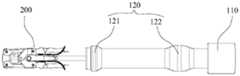
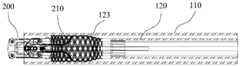
- FIG. 1is a schematic diagram of the overall structure of the transcatheter valve repair system according to the first embodiment of the disclosure.
- FIG. 2is an enlarged view of the distal end of the delivery catheter assembly according to the first embodiment of the disclosure.
- FIG. 3is a schematic structural diagram of the first auxiliary member according to the first embodiment of the disclosure.
- FIG. 4is a front view of the first auxiliary member according to the first embodiment of the disclosure.
- FIG. 5is a schematic cross-sectional view of A-A in FIG. 4 .
- FIG. 6is a right side view of the first auxiliary member according to the first embodiment of the disclosure.
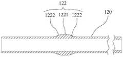
- FIG. 7is a longitudinal cross-sectional view of the second auxiliary member according to the second embodiment of the disclosure.
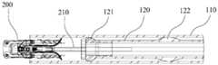
- FIG. 8is a longitudinal cross-sectional view of the delivery catheter assembly according to the second embodiment of the disclosure.
- FIG. 9is a longitudinal cross-sectional view of the implant entering the flexible sheath according to the second embodiment of the disclosure.
- FIG. 10is a schematic diagram of the overall structure of the implant entering the flexible sheath in the transcatheter valve repair system according to the second embodiment of the present disclosure.
- FIG. 11is a longitudinal cross-sectional view of the delivery catheter assembly in the loader according to the second embodiment of the disclosure.
- FIG. 12is a schematic structural diagram of the third auxiliary member and the bending sheath tube according to the third embodiment of the disclosure
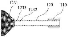
- FIG. 13is a schematic structural diagram of the third auxiliary member and the delivery catheter assembly according to the third embodiment of the disclosure.
- FIG. 14is a schematic structural diagram of the transcatheter valve repair system according to the third embodiment of the disclosure.
- FIG. 15is a schematic structural diagram of a third auxiliary member according to Embodiment 3 of the present disclosure.
- FIG. 16is a longitudinal cross-sectional view of a third auxiliary member according to Embodiment 3 of the present disclosure.
- FIG. 17is a longitudinal cross-sectional view of the third auxiliary member recovered in the bending sheath according to the third embodiment of the disclosure.
- FIG. 18is a longitudinal cross-sectional view of the third auxiliary member and the delivery catheter assembly after the implant is released according to the third embodiment of the disclosure.
- Fig. 19is a longitudinal cross-sectional view of the third auxiliary member being completely retracted into the bending sheath after the implant according to the third embodiment of the disclosure is released.
- FIG. 20is a schematic diagram of the valve clipping system used for mitral valve edge-to-edge repair of valve leaflets according to Embodiment 3 of the present disclosure.
- the proximal endrefers to the end of the instrument or component close to the operator
- the distal endrefers to the end of the instrument or component away from the operator
- the axial directionrefers to the distal end parallel to the instrument or component
- the direction of the line connecting the center of the end and the proximal end, the radial directionrefers to the direction perpendicular to the axial direction, and the circumferential direction refers to the direction surrounding the axial direction.
- a delivery catheter assemblyDisclosed are a delivery catheter assembly, a transcatheter valve repair system and a valve repair method, which can retract the implant into the delivery catheter assembly when needed, so as to conveniently adjust the position of the implant.
- a first embodiment of the present disclosurediscloses a delivery catheter assembly 100 , which includes an introducer sheath 110 and a bending sheath 120 .
- the bending sheath 120is movably passed through the introducing sheath 110 .
- the bending sheath 120is protruded with a first auxiliary member 121 near the distal end.
- the first auxiliary member 121is arranged on the outer circumference of the bending sheath 120 and is symmetrical about the central axis of the bending sheath 120.
- the first auxiliary member 121is at least partially It stops at the distal opening of the introducer sheath 110 .
- the lumen of the guide sheath 110is used to provide a delivery channel for the flexible sheath 120 and the implant 200, and the flexible sheath 120 is provided with a protruding first auxiliary member 121,
- the outer diameter of at least part of the structure of the first auxiliary member 121is larger than the inner diameter of the introducing sheath 110 , so that the first auxiliary member 121 at least partially stops the distal opening of the introducing sheath 110 .
- the implant 200After the implant 200 is protruded from the guide sheath 110, if the implant 200 does not reach the exact surgical site, the implant 200 needs to be retracted to the guide The sheath 110 is then readjusted to the extended position of the implant 200 . At this time, under the action of the retraction force, due to the large outer diameter of the first auxiliary member 121, the introducer sheath 110 will be stretched to slightly deform and enter the introducer sheath 110.
- the first auxiliary member 121has a The outer periphery and the inner wall of the guide sheath 110 are in a state of interference and fit, and there is a distance between the tube body of the bending sheath 120 and the inner wall of the guiding sheath 110 . Therefore, the implant connected to the distal end of the bending sheath 120 200 is also spaced from the inner wall of the introducer sheath 110 .
- the distancecan avoid the interference between the distal end of the introducing sheath 110 and the proximal end of the implant 200, and make the bending sheath 120 and the implantation
- the component 200is always located at the central axis of the introducer sheath 110 , so that the flexible sheath 120 and the implant 200 can be smoothly retracted into the introducer sheath 110 .
- the first auxiliary member 121includes a first connecting section 1211 and a first abutting section 1212 , the first connecting section 1211 is connected with the bending sheath 120 , and the first abutting section The maximum outer diameter of segment 1212 is greater than the inner diameter at the distal opening of introducer sheath 110 .
- the first connecting section 1211is used for connecting with the bending sheath tube 120 and is cylindrical.
- the first abutting section 1212is cylindrical, and the outer diameter of the first abutting section 1212 (ie, the maximum outer diameter of the first auxiliary member 121 ) is slightly larger than the inner diameter of the introducing sheath 110 , so as to ensure that the bending sheath 120 and the The concentricity of the introducer sheath 110 facilitates the retrieval of the implant 200 into the introducer sheath 110 .
- first abutting section 1212 and the first connecting section 1211are connected by a first transition surface 1213, and the radial dimension of the first transition surface 1213 gradually increases from the proximal end to the distal end.
- the first transition surface 1213 and the first abutting section 1212have a stepped cylindrical structure.
- the part of the first transition surface 1213will be in contact with the distal opening of the bending sheath 120, and the gradually increasing size of the first transition surface 1213 is beneficial to the bending sheath
- the tube 120is smoothly retracted into the introducer sheath 110 , and the first auxiliary member 121 is prevented from damaging the distal end surface of the introducer sheath 110 .
- the first transition surface 1213is a convex, concave, or tapered surface.
- the shape of the first transition surface 1213is for the purpose of achieving a good transition and improving the centering performance of the bending sheath 120.
- the first transition surface 1213is set as a tapered surface, and the range of the taper ⁇ can be reasonably set to ensure that The effective length at the largest diameter of the head end of the first auxiliary piece 121 (ie, the “first abutting section 1212 ”) ensures the concentricity between the bending sheath 120 and the introducing sheath 110 .
- the taper ⁇is set at about 100 to 130°. In certain embodiments, the taper ⁇ is about 110 to 120°, and the length of the first abutment segment 1212 ranges from about 1.3 to 1.0 mm.
- the outer wall or inner wall of the first connecting section 1211is provided with a first convex strip, and the inner or outer wall of the flexible sheath 120 is provided with a corresponding first notch; or, the outer wall of the first connecting section 1211 Or the inner wall is provided with a first notch, and the inner wall or the outer wall of the bending sheath 120 is provided with a corresponding first protruding strip. In this way, the first connecting section 1211 is connected to the bending sheath 120 through the mating connection between the first protruding strip and the first notch.
- the outer wall of the first connecting section 122is provided with a first slot 12111
- the inner wall of the bending sheath 120is provided with a corresponding first protruding strip.
- the connection between the first auxiliary member 121 and the bending sheath 120is realized by the snap connection between the first notch 12111 and the first convex strip, and the pull-off strength and rotation of the first connecting section 1211 and the bending sheath 120 can be improved. off strength.
- gluecan be poured into the first slot 12111 to fix the first auxiliary member 121 and the bending sheath 120 by gluing.
- the first connecting section 1211 and the bending sheath 120are fixed by welding, that is, the bending sheath 120 is wrapped and partially melted to the first connecting section of the first auxiliary member 121 by high temperature 1211, so that the front end of the bending sheath 120 is fused with the first auxiliary piece 121.
- the distal end of the first abutting segment 1212is provided with a circular arc portion 1214 to prevent scratching of the blood vessel and the inner wall of the heart.
- the radius of the arc portion 1214should be reduced as much as possible to avoid affecting the size of the first abutting section 1212 , and at the same time ensure that the first abutting section 1212 has an appropriate contact area to achieve a reasonable positioning effect.
- the radius of the arcuate portion 1214ranges from about 0.2 to 0.4 mm.
- the length of the first auxiliary member 121 along the axial direction of the flexible sheath 120ranges from about 6 to 9 mm. It can be understood that if the length of the first auxiliary member 121 is too long, the bending radius of the flexible sheath tube 120 will be affected, thereby causing the distal end of the sheath tube to abut the atrioventricular wall. The length is insufficient, which in turn affects the strength of the connection.
- the material of the first auxiliary member 121can be selected from stainless steel material, nickel titanium material or polymer material. In this embodiment, stainless steel material with high strength and good processing performance is preferably used.
- the delivery catheter assembly 100further includes an operating handle 130 disposed at the proximal end of the introducer sheath 110 , and a bending handle 140 disposed at the proximal end of the bending sheath 120 .
- the operating handle 130is used to adjust the camber and axial movement of the distal end portion of the guide sheath 110
- the bending handle 140is used to adjust the bending and axial movement of the bending sheath 120. Operates to adjust the relative position between the implant 200 and the treatment site.
- a transcatheter valve repair system 1000is also disclosed, including the delivery catheter assembly 100 and the implant 200 of the above-mentioned structures.
- the implants 200are detachably connected.
- the bending sheath 120is provided with a third auxiliary member 123
- the distal end of the third auxiliary member 123is provided with an expandable structure 1231
- the length of the expandable structure 1231is four times the length of the implant 200 . one-half to one-half.
- the implant 200is detachably disposed at the distal end of the flexible sheath 120. After the implant 200 reaches the appropriate surgical site and the implantation is completed, the implant 200 is separated from the flexible sheath 120, and then withdrawn and adjusted. By bending the sheath tube 120 and the introducer sheath tube 110, the delivery catheter assembly 100 can be withdrawn from the body, and the implant 200 can be indwelled in the patient.
- the purpose of the expandable structure 1231is to wrap the part of the implant 200 that is prone to scratches and reduce the damage to the heart caused by the implant 200 during the retraction process.
- the length of the expandable structure 1231is a quarter of the length of the implant 200. One to one half, taking into account the saving of materials and the effect of wrapping.
- the size of the heartis also different.
- the size of the implant 200will also be different.
- the lengthsare proportional to accommodate different sizes and types of implants 200.
- implant 200is a valve clamping device.
- the distal end of the flexible sheath 120is provided with a connecting rod 210 for connecting with the valve clamping device.
- the repair process of the mitral valveis briefly described below with the valve clamping device: first, the channel from the outside to the body is established by cooperating with the guide sheath 110 and the guide wire; then the proximal end of the valve clamping device and the connecting rod 210 are connected Removable connection, so as to connect the valve clamping device with the flexible sheath 120; then the flexible sheath 120 is delivered to the patient's mitral valve near the patient's mitral valve in a transcatheter manner along the introducer sheath 110, at this time the valve clamp Both the clamping device and the bending sheath 120 are accommodated in the guiding sheath 110, and can move relative to the guiding sheath 110 in the axial direction; finally, the operator operates the valve clamping device remotely to displace the mitral valve.
- the anterior leaflet and the posterior leaflet of the valveare clamped together, and once the leaflets of the mitral valve are abutted edge-to-edge, the operator can release the connection between the connecting rod 210 and the valve clamping device, thereby releasing the adjustment
- the connection between the sheath tube 120 and the valve clamping device, and then the valve clamping deviceis implanted in the patient, and the anterior leaflet and the posterior leaflet of the mitral valve are fixed together to realize the "edge-to-edge repair" of the mitral valve .
- the sheath tube 120is appropriately withdrawn to bend the first auxiliary member 121 abuts on the distal surface of the guide sheath 110, and then continues to withdraw and bend the sheath 120. At this time, the first auxiliary member 121 is gradually accommodated in the guide sheath 110, and is always in contact with the guide sheath.
- the delivery catheter assembly 100 provided in the second embodiment of the present disclosureis basically the same in structure as the delivery catheter assembly in the first embodiment, except that the bending sheath 120 is further provided with a second auxiliary member 122 .
- the outer wall of the member 122 and the inner wall of the introducer sheath 110are in clearance fit, and the second auxiliary member 122 and the first auxiliary member 121 are arranged in sequence from near to far.
- the first auxiliary member 121 and the second auxiliary member 122cooperate to form a two-point and one-line structure to jointly correct the bending sheath 120 and the guide
- the concentricity of the sheath tube 110further ensures that the distal end of the bending sheath tube 120 and the distal end of the guiding sheath tube 110 form a straight channel, ensuring that the retraction route of the implant 200 is coaxial with the guiding sheath tube 110, thereby ensuring
- the implant 200can be retracted into the introducer sheath 110 in any direction, which is more conducive to the retrieval of the implant 200 .
- the second auxiliary member 122includes a second abutting section 1221 , the outer diameter of the second abutting section 1221 is the same as the inner diameter of the introducing sheath 110 , the proximal end and the distal end of the second abutting section 1221 are the same. The ends are respectively connected smoothly with the outer wall of the bending sheath 120 through the second transition surface 1222 .
- the external structure of the second auxiliary member 122is an irregular stepped cylindrical convex structure.
- the purpose of the second transition surface 1222is to improve the smooth connection between the second abutting section 1221 and the body part of the bending sheath 120 , so as to avoid the second abutting section 1221 and the inner wall of the introducing sheath 110 from being stuck.
- the length of the second auxiliary member 122 along the axial direction of the flexible sheath 120ranges from about 5 to 10 mm.
- One of the reasons for setting this length rangeis that the concentricity between the bending sheath 120 and the guiding sheath 110 can be improved, which is conducive to the recovery of the implant 200 into the guiding sheath 110 ; the other is to avoid affecting the bending sheath 120 bending performance and bending angle.
- the distance between the distal end of the second auxiliary member 122 and the proximal end of the first auxiliary member 121 along the axial direction of the flexible sheath 120ranges from about 16 to 25 mm.
- the reason for setting this distance rangeis to prevent the second auxiliary member 122 from affecting the bending radius and bending shape of the bending sheath 120 .
- the maximum outer diameter of the second auxiliary member 122is the same as the inner diameter of the introducer sheath 110 , thereby improving the concentricity between the bending sheath 120 and the introducer sheath 110 .
- the concentricityis corrected by the first auxiliary member 121 and the second auxiliary member 122 and then recovered into the introducing sheath 110 .
- an implant 200(eg, a valve clamping device) is typically pre-installed by the manufacturer in a hollow loader 2000 at the factory. During the pre-installation process, It is necessary to withdraw the bending sheath 120 until the implant 200 is gradually accommodated in the inner cavity of the loader 2000.
- the second auxiliary member 122can ensure the concentricity between the bending sheath 120 and the inner cavity of the loader 2000, and assists the implantation
- the insertion piece 200is gradually retracted into the inner cavity of the loader 2000, and since the outer diameter of the second auxiliary piece 122 is larger than the inner diameter of the silicone valve 2100 at the proximal end of the loader 2000, it can prevent excessive retraction and bending of the sheath tube 120 to cause implantation
- the insert 200is pulled from the proximal end of the loader 2000, preventing damage to the implant 200.
- the delivery catheter assembly 100 provided in the third embodiment of the present disclosureis basically the same in structure as the delivery catheter assembly in the first embodiment.
- the proximal end of the piece 123is connected to the outer wall of the bending sheath 120, and the distal end is provided with an expandable structure 1231.
- the third auxiliary member 123is sleeved outside the distal end of the bending sheath 120.
- the expandable structure 1231can be opened and covered on the periphery of the implant member 200 through a related operation, and then followed by With gradual retraction, the expandable structure 1231 is retracted under the action of the introducer sheath 110 and retracted to the introducer sheath 110 together with the implant 200 .
- the third auxiliary member 123 and the first auxiliary member 121are arranged in order from far to near. Since the third auxiliary member 123 needs to wrap the distal implant 200, the third auxiliary member 123 is arranged at the distal end of the bending sheath 120, and the first auxiliary member 121 is arranged at the opposite proximal end, so as not to interfere with the third auxiliary member 123. Expansion and contraction of the auxiliary member 123 .
- the third embodimentcan also be combined with the structure of the second embodiment: the bending sheath 120 includes a second auxiliary member 122, and the third auxiliary member 123 is formed by the first auxiliary member 121 and the second auxiliary member 122. Far and near are set in order.
- the first auxiliary member 121 , the second auxiliary member 122 and the third auxiliary member 123cooperate together to ensure that the retraction route of the implantation member 200 is coaxial with the introducing sheath 110 , which facilitates the retraction of the implantation member 200 .
- the proximal end of the third auxiliary member 123includes a third connecting section 1232 , and the inner or outer wall of the third connecting section 1232 is provided with a third notch, and the flexible sheath 120
- the outer wall or inner wall of the bending sheath 120is provided with a corresponding third ridge;
- the third connecting section 1232is connected to the bending sheath 120 through the fitting connection between the third protruding strip and the third notch.
- the outer wall of the third connecting section 1232is provided with a third notch
- the inner wall of the bending sheath 120is provided with a corresponding third convex strip.
- connection method of the third convex strip and the third groove 12321may refer to the connection method of the first groove 12111 and the first convex strip described above.
- the total length of the third connection section 1232is set to be about 5 to 6 mm, which ensures the connection strength and does not affect the bending performance of the bending sheath 120 .
- the diameter of the expandable structure 1231gradually increases from the proximal end to the distal end, ie, the expandable structure 1231 is a hollow umbrella-like structure with an open proximal end and is connected to the flexible sheath 120 at the distal end.
- the maximum outer diameter of the expandable structure 1231ranges from about 25 to 30 mm.
- the expandable structure 1231is made of a shape memory material such as Nitinol.
- the manufacturing process of the third auxiliary member 123is as follows: first, a plurality of nickel-titanium wires are used to weave into a cylindrical structure, and then put into an umbrella-shaped shaping mold, heat-set at a high temperature of about 500 to 650°, and then the umbrella-shaped structure is The tail end and the steel sleeve 1233 are fixed together by means of polymer material welding, or bonding, welding, or riveting, so as to obtain the third auxiliary member 123 of this embodiment.
- the third auxiliary member 123 and the bending sheath 120can also be fixed by welding with a polymer material, that is, the connection between the bending sheath 120 and the third auxiliary member 123 is melted at a high temperature, so that the front end of the bending sheath 120 and the third auxiliary member 123 are melted.
- the three auxiliary pieces 123are fused together.
- the implant 200is a valve clamping device.
- the valve clamping devicefails to clamp the valve leaflet or the clamping position is not ideal, the valve clamping device needs to be withdrawn to be re-accommodated to the introducer sheath In the tube 110, at this time, by withdrawing and adjusting the sheath tube 120, the third auxiliary member 123 changes from an umbrella-shaped structure to a cylindrical structure, and the third auxiliary member 123 completely wraps the proximal end of the valve clamping device, thereby clamping the valve.
- the closing deviceis retracted into the introducer sheath 110 .
- the connecting rod 210 at the distal end of the flexible sheath 120 for connecting with the valve clamping deviceis completely exposed, and it is necessary to The delivery catheter assembly 100 is completely withdrawn from the patient's body.
- the third auxiliary member 123can completely wrap the connecting rod 210, so as to prevent the connecting rod 210 from scratching the valve leaflets and the atrium wall, improving the performance of the instrument. Safety performance and reduced surgical risk.
- the third auxiliary member 123can press the valve leaflet on the atrium side to reduce the swing range of the anterior leaflet and the posterior leaflet, thereby facilitating the valve clamping device to clamp the valve leaflet, reducing the difficulty of implantation and improving the success rate of the operation.
Landscapes
- Health & Medical Sciences (AREA)
- Cardiology (AREA)
- Oral & Maxillofacial Surgery (AREA)
- Transplantation (AREA)
- Engineering & Computer Science (AREA)
- Biomedical Technology (AREA)
- Heart & Thoracic Surgery (AREA)
- Vascular Medicine (AREA)
- Life Sciences & Earth Sciences (AREA)
- Animal Behavior & Ethology (AREA)
- General Health & Medical Sciences (AREA)
- Public Health (AREA)
- Veterinary Medicine (AREA)
- Prostheses (AREA)
Abstract
Description
Translated fromChinese相关申请的引用Citations to Related Applications
本公开要求于2020年12月30日向中华人民共和国国家知识产权局提交的申请号为202011612802.X、名称为“一种输送导管组件及经导管瓣膜修复系统”的发明专利申请以及于2020年12月30日向中华人民共和国国家知识产权局提交的申请号为202023335537.3、名称为“一种输送导管组件及经导管瓣膜修复系统”的实用新型专利申请的全部权益,并通过引用的方式将其全部内容并入本文。This disclosure requires an invention patent application with the application number 202011612802.X, entitled "A Delivery Catheter Assembly and a Transcatheter Valve Repair System" filed with the State Intellectual Property Office of the People's Republic of China on December 30, 2020, and an invention patent application filed on December 30, 2020 All rights and interests of the utility model patent application with the application number 202023335537.3 and the title of "A Delivery Catheter Assembly and Transcatheter Valve Repair System" submitted to the State Intellectual Property Office of the People's Republic of China on March 30, and the entire contents of which are incorporated by reference Incorporated herein.
领域field
本公开属于医疗器械技术领域,具体而言,涉及输送导管组件、经导管瓣膜修复系统及瓣膜修复方法。The present disclosure belongs to the technical field of medical devices, and in particular, relates to a delivery catheter assembly, a transcatheter valve repair system and a valve repair method.
背景background
心脏部位,如二尖瓣或三尖瓣疾病一般需要手术干预,恢复或改善心脏的结构和功能。为了减少手术损伤,经导管的介入式瓣膜治疗术逐渐成为首选。Parts of the heart, such as mitral or tricuspid valve disease, generally require surgical intervention to restore or improve the structure and function of the heart. In order to reduce surgical damage, transcatheter interventional valve therapy has gradually become the first choice.
现有的介入式瓣膜治疗术需要借助输送管沿血管进入心脏对应部位,将植入件对准此部位进行夹合瓣叶、切开瓣膜、植入人工瓣膜等操作。The existing interventional valve therapy requires the use of a delivery tube to enter the corresponding part of the heart along the blood vessel, and the implant is aligned with the part to perform operations such as clamping the leaflet, incising the valve, and implanting the artificial valve.
概述Overview
一方面,本公开涉及输送导管组件,包括:导引鞘管,以及调弯鞘管,所述调弯鞘管活动地穿设于所述导引鞘管中,所述调弯鞘管邻近远端处凸设有第一辅助件,所述第一辅助件设于所述调弯鞘管外周并关于所述调弯鞘管的中心轴对称,所述第一辅助件至少部分止挡于所述导引鞘管的远端开口。In one aspect, the present disclosure relates to a delivery catheter assembly, comprising: an introducer sheath, and a bendable sheath movably threaded through the introducer sheath, the bendable sheath adjacent to a distal end The end is protruded with a first auxiliary piece, the first auxiliary piece is arranged on the outer periphery of the bending sheath tube and is symmetrical with respect to the central axis of the bending sheath tube, and the first auxiliary piece at least partially stops at the the distal opening of the introducer sheath.
在某些实施方案中,第一辅助件包括第一连接段和第一抵接段, 所述第一连接段与所述调弯鞘管连接,所述第一抵接段的最大外径大于所述导引鞘管的远端开口处的内径。In some embodiments, the first auxiliary member includes a first connecting section and a first abutting section, the first connecting section is connected with the bending sheath, and the maximum outer diameter of the first abutting section is greater than The inner diameter at the distal opening of the introducer sheath.
在某些实施方案中,第一抵接段与所述第一连接段之间通过第一过渡面连接,所述第一过渡面的径向尺寸由近端向远端逐渐增大。In some embodiments, the first abutting segment and the first connecting segment are connected by a first transition surface, and the radial dimension of the first transition surface gradually increases from the proximal end to the distal end.
在某些实施方案中,第一过渡面为凸弧面、凹弧面或锥面。In certain embodiments, the first transition surface is a convex, concave or conical surface.
在某些实施方案中,第一连接段的外壁或内壁设有第一凸条,所述调弯鞘管的内壁或外壁设有对应的第一槽口;或者第一连接段的外壁或内壁设有第一槽口,所述调弯鞘管的内壁或外壁设有对应的第一凸条。In certain embodiments, the outer or inner wall of the first connecting segment is provided with a first protruding strip, and the inner or outer wall of the flexible sheath is provided with a corresponding first notch; or the outer or inner wall of the first connecting segment is provided with a first notch. A first notch is provided, and the inner wall or the outer wall of the bending sheath is provided with a corresponding first convex strip.
在某些实施方案中,第一抵接段的远端设有圆弧部。In certain embodiments, the distal end of the first abutment segment is provided with a circular arc.
在某些实施方案中,第一辅助件沿所述调弯鞘管轴向的长度范围为6至9mm。In some embodiments, the length of the first auxiliary member in the axial direction of the flexible sheath is in the range of 6 to 9 mm.
在某些实施方案中,调弯鞘管还设有第二辅助件,所述第二辅助件的外壁与所述导引鞘管的内壁之间间隙配合,所述第二辅助件和所述第一辅助件由近及远依次设置。In certain embodiments, the bending sheath is further provided with a second auxiliary member, the outer wall of the second auxiliary member and the inner wall of the introducing sheath are in clearance fit, the second auxiliary member and the The first auxiliary parts are arranged in sequence from near to far.
在某些实施方案中,第二辅助件包括第二抵接段,所述第二抵接段的外径和所述导引鞘管的内径一致,所述第二抵接段的近端和远端分别通过第二过渡面与所述调弯鞘管的外壁光滑连接。In certain embodiments, the second auxiliary member includes a second abutment section, the outer diameter of the second abutment section is the same as the inner diameter of the introducer sheath, the proximal end of the second abutment section and The distal ends are respectively connected smoothly with the outer wall of the bending sheath through the second transition surfaces.
在某些实施方案中,第二辅助件沿所述调弯鞘管轴向的长度范围为5至10mm。In some embodiments, the length of the second auxiliary member in the axial direction of the flexible sheath is in the range of 5 to 10 mm.
在某些实施方案中,第二辅助件的远端和所述第一辅助件的近端沿所述调弯鞘管轴向的间距范围为16至25mm。In certain embodiments, the distance between the distal end of the second auxiliary member and the proximal end of the first auxiliary member in the axial direction of the flexible sheath is in the range of 16 to 25 mm.
在某些实施方案中,调弯鞘管还设有第三辅助件,所述第三辅助件的近端连接于所述调弯鞘管,远端设有可扩张结构。In certain embodiments, the bending sheath is further provided with a third auxiliary member, the proximal end of the third auxiliary member is connected to the bending sheath, and the distal end is provided with an expandable structure.
在某些实施方案中,第三辅助件、所述第一辅助件及所述第二辅助件由远及近依次设置。In some implementations, the third auxiliary member, the first auxiliary member and the second auxiliary member are arranged in order from far to near.
在某些实施方案中,第三辅助件的近端包括第三连接段,所述第三连接段的内壁或外壁设有第三槽口,所述调弯鞘管的外壁或内壁设有对应的第三凸条;或者第三连接段的内壁或外壁设有第 三凸条,所述调弯鞘管的外壁或内壁设有对应的第三槽口。In some embodiments, the proximal end of the third auxiliary member includes a third connecting section, the inner wall or outer wall of the third connecting section is provided with a third notch, and the outer wall or inner wall of the bending sheath is provided with a corresponding or the inner wall or outer wall of the third connecting section is provided with a third convex strip, and the outer wall or inner wall of the bending sheath is provided with a corresponding third notch.
在某些实施方案中,可扩张结构的直径自近端至远端逐渐增加,所述可扩张结构由形状记忆材料制成。In certain embodiments, the diameter of the expandable structure gradually increases from the proximal end to the distal end, and the expandable structure is made of a shape memory material.
在某些实施方案中,输送导管组件还包括分别设于所述导引鞘管近端的操作手柄,及设于所述调弯鞘管近端的调弯手柄。In certain embodiments, the delivery catheter assembly further comprises an operating handle respectively provided at the proximal end of the introducing sheath, and a bending handle provided at the proximal end of the bending sheath.
另一方面,本公开涉及经导管瓣膜修复系统,包括上述结构的输送导管组件及植入件,所述输送导管组件配置为输送所述植入件。In another aspect, the present disclosure relates to a transcatheter valve repair system including a delivery catheter assembly and an implant of the structure described above, the delivery catheter assembly being configured to deliver the implant.
在某些实施方案中,所述调弯鞘管的远端与所述植入件之间可拆卸连接。In certain embodiments, the distal end of the flexible sheath is detachably connected to the implant.
在某些实施方案中,所述可扩张结构的长度为所述植入件的长度的四分之一至二分之一。In certain embodiments, the length of the expandable structure is one quarter to one half the length of the implant.
在某些实施方案中,所述植入件为瓣膜夹合装置。In certain embodiments, the implant is a valve clamping device.
又一方面,本公开涉及瓣膜修复方法,包括:通过导引鞘管与导丝配合建立从体外到体内的通道;将瓣膜夹合装置的近端与连接杆可拆卸连接,从而将所述瓣膜夹合装置与调弯鞘管相连;将所述调弯鞘管沿着所述导引鞘管以经导管的方式输送至患者的瓣膜附近;使用所述瓣膜夹合装置,将所述瓣膜的瓣叶夹持在一起;以及当所述瓣膜的瓣叶被缘对缘地对合在一起时,解脱所述连接杆与所述瓣膜夹合装置之间的连接,从而解脱所述调弯鞘管与所述瓣膜夹合装置之间的连接,进而将所述瓣膜夹合装置植入在患者体内,将所述瓣膜的瓣叶固定在一起。In yet another aspect, the present disclosure relates to a valve repair method, comprising: establishing a passage from outside the body to the inside of the body through the cooperation of a guide sheath with a guide wire; The clamping device is connected with the bending sheath; the bending sheath is transported to the vicinity of the valve of the patient along the introducing sheath in a transcatheter manner; using the valve clamping device, the valve leaflets are clamped together; and when the leaflets of the valve are snapped together edge-to-edge, releasing the connection between the connecting rod and the valve clamping device, thereby releasing the flexible sheath The connection between the tube and the valve clamping device, thereby implanting the valve clamping device in the patient, secures the valve leaflets together.
在某些实施方案中,瓣膜修复方法还包括:当所述瓣膜夹合装置不能夹持瓣叶或者在瓣叶上的夹持位置不理想时,适当后撤所述调弯鞘管,使辅助件抵接在所述导引鞘管的远端面;以及继续后撤所述调弯鞘管,矫正所述调弯鞘管与所述导引鞘管的同心度,使得所述瓣膜夹合装置可以在任意方向回收进所述导引鞘管内。In certain embodiments, the valve repair method further comprises: when the valve clamping device cannot clamp the valve leaflet or the clamping position on the valve leaflet is not ideal, properly withdrawing the flexible sheath to make auxiliary abutting the distal end surface of the guide sheath; and continue to withdraw the bend sheath to correct the concentricity of the bend sheath and the guide sheath, so that the valve is clamped The device can be retracted into the introducer sheath in any direction.
在某些实施方案中,瓣膜选自二尖瓣和三尖瓣。In certain embodiments, the valve is selected from the group consisting of a mitral valve and a tricuspid valve.
在某些实施方案中,本公开的输送导管组件、经导管瓣膜修 复系统及瓣膜修复方法中,导引鞘管的内腔配置为调弯鞘管及植入件提供输送通道,且调弯鞘管设有凸出的第一辅助件,第一辅助件的至少部分结构的外径尺寸大于导引鞘管的内径,使得第一辅助件至少部分止挡于导引鞘管的远端开口。在植入件的植入过程中,植入件从导引鞘管伸出后,若植入件并未达到准确的手术部位,需要使植入件先回收至导引鞘管,再重新调整植入件的伸出位置,此时在回撤力作用下,由于第一辅助件外径尺寸较大,将撑开导引鞘管使其发生轻微形变并进入导引鞘管,此时第一辅助件的外周与导引鞘管的内壁为抵触贴合状态,而调弯鞘管的管体与导引鞘管的内壁存在间距,因此,连接于调弯鞘管远端的植入件也与导引鞘管的内壁存在间距,此间距能够避免导引鞘管的远端与植入件的近端发生干涉,并使得调弯鞘管和植入件始终位于导引鞘管的中心轴处,使植入件顺利回收至导引鞘管中。In certain embodiments, in the delivery catheter assemblies, transcatheter valve repair systems, and valve repair methods of the present disclosure, the lumen of the introducer sheath is configured to provide a delivery channel for the flexible sheath and the implant, and the flexible sheath The tube is provided with a protruding first auxiliary member, and the outer diameter of at least part of the first auxiliary member is larger than the inner diameter of the introducer sheath, so that the first auxiliary member at least partially stops at the distal opening of the introducer sheath. During the implantation process, after the implant protrudes from the introducer sheath, if the implant does not reach the exact surgical site, the implant must be retracted to the introducer sheath first, and then readjusted. At the extended position of the implant, under the action of the retraction force, due to the large outer diameter of the first auxiliary member, the guide sheath will be stretched to slightly deform and enter the guide sheath. The outer periphery of an auxiliary piece and the inner wall of the guide sheath are in a state of interference and fit, and there is a distance between the tube body of the bending sheath and the inner wall of the guiding sheath. Therefore, the implant connected to the distal end of the bending sheath There is also a distance from the inner wall of the introducer sheath, which can prevent the distal end of the introducer sheath from interfering with the proximal end of the implant, and keep the flexible sheath and the implant in the center of the introducer sheath. shaft, so that the implant can be smoothly retracted into the introducer sheath.
附图的简要说明Brief Description of Drawings
此处的附图被并入说明书中并构成本说明书的一部分,示出了符合本公开的实施例,并与说明书一起用于解释本公开的原理。The accompanying drawings, which are incorporated in and constitute a part of this specification, illustrate embodiments consistent with the disclosure and together with the description serve to explain the principles of the disclosure.
为了更清楚地说明本公开实施例中的技术方案,下面将对实施例中所需要使用的附图作简单地介绍,显而易见地,对于本领域普通技术人员而言,在不付出创造性劳动性的前提下,还可以根据这些附图获得其他的附图。In order to illustrate the technical solutions in the embodiments of the present disclosure more clearly, the accompanying drawings required in the embodiments will be briefly introduced below. Obviously, for those skilled in the art, without creative efforts On the premise, other drawings can also be obtained according to these drawings.
图1为本公开实施例一的经导管瓣膜修复系统的整体结构示意图。FIG. 1 is a schematic diagram of the overall structure of the transcatheter valve repair system according to the first embodiment of the disclosure.
图2为本公开实施例一的输送导管组件的远端放大图。FIG. 2 is an enlarged view of the distal end of the delivery catheter assembly according to the first embodiment of the disclosure.
图3为本公开实施例一的第一辅助件的结构示意图。FIG. 3 is a schematic structural diagram of the first auxiliary member according to the first embodiment of the disclosure.
图4为本公开实施例一的第一辅助件的正视图。FIG. 4 is a front view of the first auxiliary member according to the first embodiment of the disclosure.
图5为图4中A-A的截面示意图。FIG. 5 is a schematic cross-sectional view of A-A in FIG. 4 .
图6为本公开实施例一的第一辅助件的右视图。FIG. 6 is a right side view of the first auxiliary member according to the first embodiment of the disclosure.
图7为本公开实施例二的第二辅助件的纵向剖面图。FIG. 7 is a longitudinal cross-sectional view of the second auxiliary member according to the second embodiment of the disclosure.
图8为本公开实施例二的输送导管组件的纵向剖面图。8 is a longitudinal cross-sectional view of the delivery catheter assembly according to the second embodiment of the disclosure.
图9为本公开实施例二的植入件进入调弯鞘管的纵向剖面图。FIG. 9 is a longitudinal cross-sectional view of the implant entering the flexible sheath according to the second embodiment of the disclosure.
图10本公开实施例二的经导管瓣膜修复系统中植入件进入调弯鞘管的整体结构示意图。FIG. 10 is a schematic diagram of the overall structure of the implant entering the flexible sheath in the transcatheter valve repair system according to the second embodiment of the present disclosure.
图11为本公开实施例二的输送导管组件在装载器中的纵向剖面图。11 is a longitudinal cross-sectional view of the delivery catheter assembly in the loader according to the second embodiment of the disclosure.
图12为本公开实施例三的第三辅助件与调弯鞘管的结构示意图12 is a schematic structural diagram of the third auxiliary member and the bending sheath tube according to the third embodiment of the disclosure
图13为本公开实施例三的第三辅助件及输送导管组件的结构示意图。13 is a schematic structural diagram of the third auxiliary member and the delivery catheter assembly according to the third embodiment of the disclosure.
图14为本公开实施例三的经导管瓣膜修复系统的结构示意图。FIG. 14 is a schematic structural diagram of the transcatheter valve repair system according to the third embodiment of the disclosure.
图15为本公开实施例三的第三辅助件的结构示意图。FIG. 15 is a schematic structural diagram of a third auxiliary member according to Embodiment 3 of the present disclosure.
图16为本公开实施例三的第三辅助件的纵向剖面图。16 is a longitudinal cross-sectional view of a third auxiliary member according to Embodiment 3 of the present disclosure.
图17为本公开实施例三的第三辅助件回收于调弯鞘管的纵向剖面图。FIG. 17 is a longitudinal cross-sectional view of the third auxiliary member recovered in the bending sheath according to the third embodiment of the disclosure.
图18为本公开实施例三的植入件释放后第三辅助件及输送导管组件的纵向剖视图。18 is a longitudinal cross-sectional view of the third auxiliary member and the delivery catheter assembly after the implant is released according to the third embodiment of the disclosure.
图19为本公开实施例三的植入件释放后第三辅助件完全回收于调弯鞘管的纵向剖视图。Fig. 19 is a longitudinal cross-sectional view of the third auxiliary member being completely retracted into the bending sheath after the implant according to the third embodiment of the disclosure is released.
图20为根据本公开实施例三的瓣膜夹合系统用于二尖瓣缘对缘修复瓣叶的示意图。FIG. 20 is a schematic diagram of the valve clipping system used for mitral valve edge-to-edge repair of valve leaflets according to Embodiment 3 of the present disclosure.
详述detail
为使本公开实施例的目的、技术方案和优点更加清楚,下面将结合本公开实施例中的附图,对本公开实施例中的技术方案进行清楚、完整地描述,显然,所描述的实施例是本公开的一部分实施例,而不是全部的实施例。基于本公开中的实施例,本领域普通技术人员在没有做出创造性劳动的前提下所获得的所有其他实施例,都属于本公开保护的范围。In order to make the purposes, technical solutions and advantages of the embodiments of the present disclosure clearer, the technical solutions in the embodiments of the present disclosure will be described clearly and completely below with reference to the accompanying drawings in the embodiments of the present disclosure. Obviously, the described embodiments These are some, but not all, embodiments of the present disclosure. Based on the embodiments in the present disclosure, all other embodiments obtained by those of ordinary skill in the art without creative work fall within the protection scope of the present disclosure.
需要理解的是,“前”、“后”、“上”、“下”、“左”、“右”、“纵”、“横”、“竖直”、“水平”、“顶”、“底”、“内”、“外”、“头”、“尾”等 指示的方位或位置关系为基于附图的方位或位置关系、以特定的方位构造和操作,仅是为了便于描述本技术方案,而不是指示所指的装置或元件必须具有特定的方位,因此不能理解为对本公开的限制。It should be understood that "front", "rear", "up", "down", "left", "right", "vertical", "horizontal", "vertical", "horizontal", "top", The orientation or positional relationship indicated by "bottom", "inner", "outer", "head", "tail", etc. is based on the orientation or positional relationship of the drawings, constructed and operated in a specific orientation, and is only for the convenience of describing the present invention. technical solutions, rather than indicating that the indicated device or element must have a specific orientation, so it should not be construed as a limitation on the present disclosure.
还需要说明的是,除非另有明确的规定和限定,“安装”、“相连”、“连接”、“固定”、“设置”等术语应做广义理解,例如,可以是固定连接,也可以是可拆卸连接,或成一体;可以是直接相连,也可以通过中间媒介间接相连,可以是两个元件内部的连通或两个元件的相互作用关系。当一个元件被称为在另一元件“上”或“下”时,该元件能够“直接地”或“间接地”位于另一元件之上,或者也可能存在一个或更多个居间元件。对于本领域的普通技术人员而言,可以根据具体情况理解上述术语在本公开中的具体含义。It should also be noted that, unless otherwise expressly specified and limited, terms such as "installation", "connection", "connection", "fixation" and "setup" should be understood in a broad sense, for example, it may be a fixed connection, or a It is a detachable connection or an integral body; it can be directly connected or indirectly connected through an intermediate medium, and it can be the internal communication of two elements or the interaction relationship between the two elements. When an element is referred to as being "on" or "under" another element, it can be "directly" or "indirectly" on the other element, or one or more intervening elements may also be present. For those of ordinary skill in the art, the specific meanings of the above terms in the present disclosure can be understood according to specific situations.
在本公开的描述中,仍需要说明的是,近端是指器械或部件靠近操作者的一端,远端是指器械或部件远离操作者的一端;轴向是指平行于器械或部件的远端与近端中心连线的方向,径向是指垂直于轴向的方向,周向是指环绕轴向的方向。In the description of the present disclosure, it should be noted that the proximal end refers to the end of the instrument or component close to the operator, the distal end refers to the end of the instrument or component away from the operator; the axial direction refers to the distal end parallel to the instrument or component The direction of the line connecting the center of the end and the proximal end, the radial direction refers to the direction perpendicular to the axial direction, and the circumferential direction refers to the direction surrounding the axial direction.
公开了输送导管组件、经导管瓣膜修复系统及瓣膜修复方法,能够在需要时将植入件收回输送导管组件内,方便调节植入件的位置。下面通过具体实施例和说明书附图对公开进行阐述。Disclosed are a delivery catheter assembly, a transcatheter valve repair system and a valve repair method, which can retract the implant into the delivery catheter assembly when needed, so as to conveniently adjust the position of the implant. The disclosure is described below through specific embodiments and accompanying drawings of the description.
实施例一Example 1
参阅图1和图2,本公开实施例一公开了输送导管组件100,包括导引鞘管110和调弯鞘管120。调弯鞘管120活动地穿设于导引鞘管110中。调弯鞘管120邻近远端处凸设有第一辅助件121,第一辅助件121设于调弯鞘管120外周并关于调弯鞘管120的中心轴对称,第一辅助件121至少部分止挡于导引鞘管110的远端开口。Referring to FIGS. 1 and 2 , a first embodiment of the present disclosure discloses a
本公开的输送导管组件100,导引鞘管110的内腔用于为调弯鞘管120及植入件200提供输送通道,且调弯鞘管120设有凸出的第一辅助件121,第一辅助件121的至少部分结构的外径尺寸大 于导引鞘管110的内径,使得第一辅助件121至少部分止挡于导引鞘管110的远端开口。在植入件200的植入过程中,植入件200从导引鞘管110中伸出后,若植入件200并未达到准确的手术部位,需要使植入件200先回收至导引鞘管110,再重新调整植入件200的伸出位置。此时在回撤力作用下,由于第一辅助件121外径尺寸较大,将撑开导引鞘管110使其发生轻微形变并进入导引鞘管110,此时第一辅助件121的外周与导引鞘管110的内壁为抵触贴合状态,而调弯鞘管120的管体与导引鞘管110的内壁存在间距,因此,连接于调弯鞘管120远端的植入件200也与导引鞘管110的内壁存在间距。由于第一辅助件121关于调弯鞘管120的中心轴对称,此间距能够避免导引鞘管110的远端与植入件200的近端发生干涉,并使得调弯鞘管120和植入件200始终位于导引鞘管110的中心轴处,使调弯鞘管120和植入件200顺利回收至导引鞘管110中。In the
在某些实施方案中,参阅图3至图6,第一辅助件121包括第一连接段1211和第一抵接段1212,第一连接段1211与调弯鞘管120连接,第一抵接段1212的最大外径大于导引鞘管110的远端开口处的内径。本实施例中,第一连接段1211用于与调弯鞘管120相连,呈圆柱形。第一抵接段1212呈圆柱形,第一抵接段1212的外径(即,第一辅助件121的最大外径)稍大于导引鞘管110的内径,从而保证调弯鞘管120与导引鞘管110的同心度,有利于植入件200被回收进导引鞘管110内。In some embodiments, referring to FIG. 3 to FIG. 6 , the first
在某些实施方案中,第一抵接段1212与第一连接段1211之间通过第一过渡面1213连接,第一过渡面1213的径向尺寸由近端向远端逐渐增大。第一过渡面1213和第一抵接段1212呈阶梯圆柱结构。其中,在调弯鞘管120的回收过程中,第一过渡面1213的部分会与调弯鞘管120的远端开口接触,而第一过渡面1213逐渐增大的尺寸,有利于调弯鞘管120顺畅回收进导引鞘管110内,并且避免第一辅助件121损伤导引鞘管110的远端面。In some embodiments, the
在某些实施方案中,第一过渡面1213为凸弧面、凹弧面或锥 面。第一过渡面1213的形状以实现良好的过渡和提高调弯鞘管120的对中性能为目的,本实施例将第一过渡面1213设为锥面,通过合理设置锥度α的范围,可以保证第一辅助件121头端的最大直径处(即,“第一抵接段1212”)的有效长度,从而保证调弯鞘管120与导引鞘管110之间的同心度。锥度α过小会导致在调弯鞘管120回收进导引鞘管110内时受到较大阻力,且容易损伤导引鞘管110的远端面;锥度α过大会影响第一抵接段1212的有效长度,导致调弯鞘管120与导引鞘管110的同心度降低。在某些实施方案中,锥形的锥度α设置为约100至130°。在某些实施方案中,锥度α约为110至120°,第一抵接段1212的长度范围约为1.3至1.0mm。In certain embodiments, the
在某些实施方案中,第一连接段1211的外壁或内壁设有第一凸条,调弯鞘管120的内壁或外壁设有对应的第一槽口;或者,第一连接段1211的外壁或内壁设有第一槽口,调弯鞘管120的内壁或外壁设有对应的第一凸条。如此,通过第一凸条与第一槽口的配合连接,将第一连接段1211与调弯鞘管120连接。本实施例中,第一连接段122的外壁设有第一槽口12111,调弯鞘管120的内壁设有对应的第一凸条。第一槽口12111和第一凸条之间通过卡接实现第一辅助件121和调弯鞘管120的连接,并且可以提高第一连接段1211和调弯鞘管120的拉脱强度和旋脱强度。在某些实施方案中,可在第一槽口12111灌注胶水,通过胶粘固定第一辅助件121和调弯鞘管120。在某些实施方案中,将第一连接段1211与调弯鞘管120之间通过熔接固定,即,通过高温使调弯鞘管120包裹并部分熔化至第一辅助件121的第一连接段1211,从而将调弯鞘管120前端与第一辅助件121熔合。In some embodiments, the outer wall or inner wall of the first connecting
在某些实施方案中,第一抵接段1212的远端设有圆弧部1214,以防止刮伤血管及心脏内壁。圆弧部1214的半径应当尽量降低,以避免对第一抵接段1212的尺寸造成影响,同时保证第一抵接段1212具备适当的抵触面积,达到合理的定位效果。在某些实施方案中,圆弧部1214的半径范围约为0.2至0.4mm。In some embodiments, the distal end of the
在某些实施方案中,第一辅助件121沿调弯鞘管120轴向的长度范围约为6至9mm。可以理解,第一辅助件121的长度过长会影响调弯鞘管120的弯曲半径,进而导致鞘管远端抵顶房室壁,过短会导致第一辅助件121的第一连接段1211的长度不足,进而影响连接强度。In some embodiments, the length of the first
第一辅助件121的材料可选择不锈钢材料、镍钛材料或者高分子材料,本实施例优先采用具有高强度和良好的加工性能的不锈钢材料。The material of the first
再次参阅图1,在某些实施方案中,输送导管组件100还包括分别设于导引鞘管110近端的操作手柄130,及设于调弯鞘管120近端的调弯手柄140。操作手柄130用于调节导引鞘管110的远端部分的弯度和轴向移动,调弯手柄140则用于调节调弯鞘管120的弯曲和轴向移动,二者相互配合,在患者体外操作以调整植入件200与治疗位点之间的相对位置。Referring again to FIG. 1 , in some embodiments, the
再次参阅图1,还公开了经导管瓣膜修复系统1000,包括上述结构的输送导管组件100及植入件200,输送导管组件100用于输送植入件200,调弯鞘管120的远端与植入件200之间可拆卸连接。参阅图12至图14,调弯鞘管120设有第三辅助件123,第三辅助件123的远端设有可扩张结构1231,可扩张结构1231的长度为植入件200的长度的四分之一至二分之一。Referring again to FIG. 1 , a transcatheter
植入件200可拆卸地设置在调弯鞘管120的远端,在植入件200到达合适手术部位并植入完成后,将植入件200与调弯鞘管120分离,然后回撤调弯鞘管120及导引鞘管110,就可将输送导管组件100撤出体外,将植入件200留置在患者体内。可扩张结构1231目的是将植入件200容易造成剐蹭的部分包裹,减少植入件200在回撤过程中对心脏造成损伤,可扩张结构1231的长度为植入件200的长度的四分之一至二分之一,兼顾节省用料和包裹效果。由于患者的身高、年龄、性别等个体差异,心脏的尺寸也不同,为了配合不同大小的心脏,植入件200的尺寸也会有所差别,将可扩张结构1231的长度与植入件200的长度呈比例设置, 适用不同尺寸和类型的植入件200。The
在某些实施方案中,植入件200为瓣膜夹合装置。调弯鞘管120远端设有用于与瓣膜夹合装置相连的连接杆210。下面以瓣膜夹合装置来简单阐述二尖瓣的修复过程:首先通过导引鞘管110与导丝配合建立从体外到体内的通道;然后将瓣膜夹合装置的近端与连接杆210之间可拆卸连接,从而将瓣膜夹合装置与调弯鞘管120相连;再将调弯鞘管120沿着导引鞘管110以经导管的方式输送至患者的二尖瓣附近,此时瓣膜夹合装置及调弯鞘管120均收容在导引鞘管110中,并可与导引鞘管110之间沿轴向相对运动;最后操作者通过远距离操作瓣膜夹合装置,将二尖瓣的前叶和后叶夹持在一起,一旦二尖瓣的瓣叶被缘对缘地对合在一起,操作者即可解脱连接杆210与瓣膜夹合装置之间的连接,从而解脱调弯鞘管120与瓣膜夹合装置之间的连接,进而将瓣膜夹合装置植入在患者体内,将二尖瓣的前叶和后叶固定在一起,实现二尖瓣的“缘对缘修复”。在瓣膜夹合装置的植入过程中,如瓣膜夹合装置出现故障不能夹持瓣叶或者在瓣叶上的夹持位置不理想时,适当后撤调弯鞘管120,使第一辅助件121抵接在导引鞘管110的远端面,然后继续后撤调弯鞘管120,此时第一辅助件121逐渐收容至导引鞘管110中,并且始终抵接在导引鞘管110的内腔,从而矫正调弯鞘管120与导引鞘管110的同心度,保证瓣膜夹合装置回撤路线与导引鞘管110同轴,避免导引鞘管110的远端面与瓣膜夹合装置的钳臂或其他部件之间产生干涉,使得瓣膜夹合装置可以在任意方向回收进导引鞘管110内,之后即可调整导引鞘管110的远端位置并再次推出瓣膜夹合装置或者将导引鞘管110及瓣膜夹合装置整体撤出体外。In certain embodiments,
实施例二Embodiment 2
参阅图7至图9,本公开实施例二提供的输送导管组件100与实施例一的输送导管组件结构基本相同,区别在于:调弯鞘管120还设有第二辅助件122,第二辅助件122的外壁与导引鞘管110的 内壁之间间隙配合,第二辅助件122和第一辅助件121由近及远依次设置。Referring to FIGS. 7 to 9 , the
在某些实施方案中,当植入件200出现故障不能实现手术操作时,第一辅助件121和第二辅助件122配合,形成两点一线的结构,共同矫正调弯鞘管120与导引鞘管110的同心度,进一步保证了调弯鞘管120远端与导引鞘管110远端形成一条直线通道,保证植入件200的回撤路线与导引鞘管110同轴,从而保证植入件200可以在任意方向回收进导引鞘管110内,更有利于植入件200的回收。In some embodiments, when the
在某些实施方案中,第二辅助件122包括第二抵接段1221,第二抵接段1221的外径和导引鞘管110的内径一致,第二抵接段1221的近端和远端分别通过第二过渡面1222与调弯鞘管120的外壁光滑连接。第二辅助件122的外形结构为不规则的阶梯圆柱凸起结构。第二过渡面1222的目的是提高第二抵接段1221和调弯鞘管120的管体部分的圆滑连接,避免第二抵接段1221与导引鞘管110的内壁发生卡顿。In some embodiments, the second
在某些实施方案中,第二辅助件122沿调弯鞘管120轴向的长度范围约为5至10mm。此长度范围设置的原因其一是可以提高调弯鞘管120与导引鞘管110的同心度,有利于植入件200回收进导引鞘管110;其二是避免影响调弯鞘管120的调弯性能和弯曲角度。In some embodiments, the length of the second
在某些实施方案中,第二辅助件122的远端和第一辅助件121的近端沿调弯鞘管120轴向的间距范围约为16至25mm。此间距范围设置的原因是避免第二辅助件122影响调弯鞘管120的弯曲半径和弯曲形状。第二辅助件122的最大外径与导引鞘管110的内径相同,从而提高了调弯鞘管120与导引鞘管110的同心度。In some embodiments, the distance between the distal end of the second
参阅图9和图10,植入件200如瓣膜夹合装置在关闭状态后,通过第一辅助件121和第二辅助件122矫正同心度后回收进导引鞘管110内。Referring to FIGS. 9 and 10 , after the
在某些实施方案中,参阅图11,在其它实施例中,植入件200 (如瓣膜夹合装置)在出厂时通常由厂家预装在中空的装载器2000中,在预装过程中,需要后撤调弯鞘管120直至植入件200逐渐收容至装载器2000的内腔,第二辅助件122可以保证调弯鞘管120与装载器2000内腔之间的同心度,辅助将植入件200逐渐收进装载器2000的内腔中,并且由于第二辅助件122的外径大于装载器2000近端的硅胶阀门2100的内径,可以防止过度后撤调弯鞘管120而导致植入件200自装载器2000近端被拉出,防止植入件200损坏。In certain embodiments, referring to FIG. 11, in other embodiments, an implant 200 (eg, a valve clamping device) is typically pre-installed by the manufacturer in a
实施例三Embodiment 3
参阅图12至图14,本公开实施例三提供的输送导管组件100与实施例一的输送导管组件结构基本相同,区别在于:调弯鞘管120还设有第三辅助件123,第三辅助件123的近端连接于调弯鞘管120的外壁,远端设有可扩张结构1231。第三辅助件123套设在调弯鞘管120远端外,在需要回撤植入件200时,可通过相关操作使可扩张结构1231张开并罩于植入件200的外周,然后随着逐步后缩,可扩张结构1231在导引鞘管110的作用下收拢,并和植入件200一同收回到导引鞘管110。Referring to FIGS. 12 to 14 , the
在某些实施方案中,第三辅助件123和第一辅助件121由远及近依次设置。由于第三辅助件123需要包裹远端的植入件200,因此第三辅助件123设置在调弯鞘管120的远端,第一辅助件121设置在相对的近端,不会妨碍第三辅助件123的扩张和收缩。In some embodiments, the third
在某些实施方案中,实施例三还可以与实施例二的结构结合:调弯鞘管120包括第二辅助件122,第三辅助件123与第一辅助件121、第二辅助件122由远及近依次设置。第一辅助件121、第二辅助件122和第三辅助件123共同配合,保证植入件200的回撤路线与导引鞘管110同轴,有利于植入件200的回撤。In some embodiments, the third embodiment can also be combined with the structure of the second embodiment: the bending
在某些实施方案中,参阅图15和图16,第三辅助件123的近端包括第三连接段1232,第三连接段1232的内壁或外壁设有第三槽口,调弯鞘管120的外壁或内壁设有对应的第三凸条;或者, 第三连接段1232的内壁或外壁设有第三凸条,调弯鞘管120的外壁或内壁设有对应的第三槽口。如此,通过第三凸条与第三槽口的配合连接,将第三连接段1232与调弯鞘管120连接。本实施例中,第三连接段1232的外壁设有第三槽口,调弯鞘管120的内壁设有对应的第三凸条。第三凸条和第三槽口12321的连接方式可参照前述第一槽口12111和第一凸条的连接方式。第三连接段1232的总长度设置为约5至6mm,保证了连接强度以及不会对调弯鞘管120的调弯性能造成影响。In certain embodiments, referring to FIGS. 15 and 16 , the proximal end of the third
在某些实施方案中,可扩张结构1231的直径自近端至远端逐渐增加,即,可扩张结构1231为中空的伞状结构,近端敞口,远端连接于调弯鞘管120。可扩张结构1231的最大外径范围约为25至30mm。可扩张结构1231由镍钛合金等形状记忆材料制成。In certain embodiments, the diameter of the
第三辅助件123的制作过程如下:先采用多根镍钛金属丝编织为筒状结构,再放入伞状的定型模具中,于约500至650°高温热定型,然后将伞状结构的尾端与钢套1233通过高分子材料熔接、或者粘接、焊接、铆接的方式固定在一起,即可得到本实施例的第三辅助件123。The manufacturing process of the third
第三辅助件123与调弯鞘管120还可通过高分子材料熔接固定,即使用高温将调弯鞘管120与第三辅助件123的连接处熔化,从而将调弯鞘管120前端与第三辅助件123熔合在一起。The third
请参阅图17,植入件200为瓣膜夹合装置,当瓣膜夹合装置出现故障不能夹持瓣叶或者夹持位置不理想时,需后撤瓣膜夹合装置使其重新收容至导引鞘管110中,此时通过后撤调弯鞘管120,第三辅助件123由伞状结构变化为筒状结构,第三辅助件123完全包裹住瓣膜夹合装置的近端,从而将瓣膜夹合装置收进导引鞘管110内。Please refer to FIG. 17 , the
在某些实施方案中,请参阅图18和图19,在瓣膜夹合装置释放后,调弯鞘管120远端用于与瓣膜夹合装置相连的连接杆210完全暴露在外,此时需要将输送导管组件100整个撤出患者体内,在回撤调弯鞘管120过程中,第三辅助件123可以完全包裹住连 接杆210,从而避免连接杆210划伤瓣叶和心房壁,提高器械的安全性能和降低手术风险。In certain embodiments, referring to FIGS. 18 and 19 , after the valve clamping device is released, the connecting
在某些实施方案中,请参阅图20,本实施例提供的经导管瓣膜修复系统用于二尖瓣缘对缘修复时,在瓣膜夹合装置夹持二尖瓣的前叶和后叶之前,第三辅助件123可以在心房侧压住瓣叶,减轻前叶和后叶的摆动幅度,从而利于瓣膜夹合装置夹持瓣叶,降低植入难度,提高手术成功率。In certain embodiments, referring to FIG. 20, when the transcatheter valve repair system provided in this example is used for edge-to-edge repair of the mitral valve, before the valve clamping device clamps the anterior and posterior leaflets of the mitral valve , the third
Claims (22)
Translated fromChineseApplications Claiming Priority (4)
| Application Number | Priority Date | Filing Date | Title |
|---|---|---|---|
| CN202011612802.X | 2020-12-30 | ||
| CN202023335537.3UCN215130894U (en) | 2020-12-30 | 2020-12-30 | Delivery catheter assembly and transcatheter valve repair system |
| CN202011612802.XACN114681136B (en) | 2020-12-30 | 2020-12-30 | A delivery catheter assembly and a transcatheter valve repair system |
| CN202023335537.3 | 2020-12-30 |
Publications (1)
| Publication Number | Publication Date |
|---|---|
| WO2022143141A1true WO2022143141A1 (en) | 2022-07-07 |
Family
ID=82258653
Family Applications (1)
| Application Number | Title | Priority Date | Filing Date |
|---|---|---|---|
| PCT/CN2021/137759CeasedWO2022143141A1 (en) | 2020-12-30 | 2021-12-14 | Delivery catheter assembly, transcatheter valve repair system, and valve repair method |
Country Status (1)
| Country | Link |
|---|---|
| WO (1) | WO2022143141A1 (en) |
Cited By (4)
| Publication number | Priority date | Publication date | Assignee | Title |
|---|---|---|---|---|
| CN116585072A (en)* | 2023-05-16 | 2023-08-15 | 晨兴(南通)医疗器械有限公司 | Valve recovery device and method of use |
| CN116725621A (en)* | 2023-03-22 | 2023-09-12 | 上海玮启医疗器械有限公司 | An adjustable and curved intracardiac tumor and foreign body removal device |
| WO2024140080A1 (en)* | 2022-12-29 | 2024-07-04 | 先健科技(深圳)有限公司 | Bending-adjustable delivery sheath |
| CN118986594A (en)* | 2024-10-25 | 2024-11-22 | 科瑞迈吉(苏州)医疗科技有限公司 | Conveying system for valve repair |
Citations (5)
| Publication number | Priority date | Publication date | Assignee | Title |
|---|---|---|---|---|
| CN202859386U (en)* | 2012-09-28 | 2013-04-10 | 乐普(北京)医疗器械股份有限公司 | System for delivering artificial cardiac valve through catheter |
| CN103431926A (en)* | 2013-09-04 | 2013-12-11 | 杭州启明医疗器械有限公司 | Sheath-core for conveying interventional device and conveying system with sheath-core |
| CN107405198A (en)* | 2015-03-20 | 2017-11-28 | 耶拿阀门科技股份有限公司 | Heart valve prosthesis induction system and the method that heart valve prosthesis is conveyed with inducting device sheath |
| US20180092744A1 (en)* | 2016-10-05 | 2018-04-05 | Randolf Von Oepen | Systems and methods for delivering and deploying an artificial heart valve within the mitral annulus |
| CN209678757U (en)* | 2018-08-31 | 2019-11-26 | 上海微创心通医疗科技有限公司 | Conveying device |
- 2021
- 2021-12-14WOPCT/CN2021/137759patent/WO2022143141A1/ennot_activeCeased
Patent Citations (6)
| Publication number | Priority date | Publication date | Assignee | Title |
|---|---|---|---|---|
| CN202859386U (en)* | 2012-09-28 | 2013-04-10 | 乐普(北京)医疗器械股份有限公司 | System for delivering artificial cardiac valve through catheter |
| CN103431926A (en)* | 2013-09-04 | 2013-12-11 | 杭州启明医疗器械有限公司 | Sheath-core for conveying interventional device and conveying system with sheath-core |
| CN107405198A (en)* | 2015-03-20 | 2017-11-28 | 耶拿阀门科技股份有限公司 | Heart valve prosthesis induction system and the method that heart valve prosthesis is conveyed with inducting device sheath |
| US20180092744A1 (en)* | 2016-10-05 | 2018-04-05 | Randolf Von Oepen | Systems and methods for delivering and deploying an artificial heart valve within the mitral annulus |
| EP3503813A1 (en)* | 2016-10-05 | 2019-07-03 | Randolf Von Oepen | Systems for delivering and deploying an artificial heart valve within the mitral annulus |
| CN209678757U (en)* | 2018-08-31 | 2019-11-26 | 上海微创心通医疗科技有限公司 | Conveying device |
Cited By (6)
| Publication number | Priority date | Publication date | Assignee | Title |
|---|---|---|---|---|
| WO2024140080A1 (en)* | 2022-12-29 | 2024-07-04 | 先健科技(深圳)有限公司 | Bending-adjustable delivery sheath |
| CN116725621A (en)* | 2023-03-22 | 2023-09-12 | 上海玮启医疗器械有限公司 | An adjustable and curved intracardiac tumor and foreign body removal device |
| CN116585072A (en)* | 2023-05-16 | 2023-08-15 | 晨兴(南通)医疗器械有限公司 | Valve recovery device and method of use |
| CN116585072B (en)* | 2023-05-16 | 2024-03-26 | 晨兴(南通)医疗器械有限公司 | Valve recovery device and method of use |
| CN118986594A (en)* | 2024-10-25 | 2024-11-22 | 科瑞迈吉(苏州)医疗科技有限公司 | Conveying system for valve repair |
| US12409037B1 (en) | 2024-10-25 | 2025-09-09 | Creative Medtech (Suzhou) Co., Ltd. | Delivery system for valve repair |
Similar Documents
| Publication | Publication Date | Title |
|---|---|---|
| WO2022143141A1 (en) | Delivery catheter assembly, transcatheter valve repair system, and valve repair method | |
| US12059351B2 (en) | Annuloplasty device | |
| US11020228B2 (en) | Anchor delivery system and methods for valve repair | |
| EP4147741A1 (en) | Control handle, bending control line and implant delivery device | |
| CN113040978B (en) | Transcatheter anchor implantation device and transcatheter anchor implantation system | |
| EP4079260A1 (en) | Controllable guiding device for implantable apparatus | |
| WO2023029724A1 (en) | Transcatheter annulus reduction system and application thereof | |
| WO2023029725A1 (en) | Anti-tangling conveying device, and transcatheter annulus contraction system and application thereof | |
| WO2020043204A1 (en) | Delivery device | |
| US4111190A (en) | Medical applicator assembly for chain cystourethrographic procedure | |
| CN115212426B (en) | Delivery sheath and delivery system for interventional treatment of structural heart disease | |
| CN211934165U (en) | Valve suture instrument | |
| CN114681136A (en) | Delivery catheter assembly and transcatheter valve repair system | |
| WO2020238725A1 (en) | Heart valve prosthesis and system | |
| WO2023029726A1 (en) | Anchor assembly having threading ring, implant, and transcatheter ring contraction system | |
| WO2022206524A1 (en) | Implantation instrument system capable of reducing diameter of loading tube | |
| WO2025118705A1 (en) | Prosthetic valve delivery apparatus and system | |
| CN211156474U (en) | Medical implant delivery device | |
| CN215130894U (en) | Delivery catheter assembly and transcatheter valve repair system | |
| CN113545889B (en) | A position control device for an implant | |
| CN219230262U (en) | A cerebral embolism protection device and a system with a remote cerebral embolism protection device | |
| CN219147693U (en) | Implant delivery system | |
| CN119097469A (en) | Artificial valve prosthesis replacement system | |
| WO2020063793A1 (en) | Cardiac pacing system and pacemaker fixing device | |
| WO2023124638A1 (en) | Implantation device with clamping and guiding functions |
Legal Events
| Date | Code | Title | Description |
|---|---|---|---|
| 121 | Ep: the epo has been informed by wipo that ep was designated in this application | Ref document number:21913882 Country of ref document:EP Kind code of ref document:A1 | |
| NENP | Non-entry into the national phase | Ref country code:DE | |
| 122 | Ep: pct application non-entry in european phase | Ref document number:21913882 Country of ref document:EP Kind code of ref document:A1 |