WO2022139045A1 - Spine surgical guide and spine surgical cage therefor - Google Patents
Spine surgical guide and spine surgical cage thereforDownload PDFInfo
- Publication number
- WO2022139045A1 WO2022139045A1PCT/KR2020/019157KR2020019157WWO2022139045A1WO 2022139045 A1WO2022139045 A1WO 2022139045A1KR 2020019157 WKR2020019157 WKR 2020019157WWO 2022139045 A1WO2022139045 A1WO 2022139045A1
- Authority
- WO
- WIPO (PCT)
- Prior art keywords
- cage
- slider
- spine surgery
- coupled
- surgery
- Prior art date
- Legal status (The legal status is an assumption and is not a legal conclusion. Google has not performed a legal analysis and makes no representation as to the accuracy of the status listed.)
- Ceased
Links
Images


Classifications
- A—HUMAN NECESSITIES
- A61—MEDICAL OR VETERINARY SCIENCE; HYGIENE
- A61F—FILTERS IMPLANTABLE INTO BLOOD VESSELS; PROSTHESES; DEVICES PROVIDING PATENCY TO, OR PREVENTING COLLAPSING OF, TUBULAR STRUCTURES OF THE BODY, e.g. STENTS; ORTHOPAEDIC, NURSING OR CONTRACEPTIVE DEVICES; FOMENTATION; TREATMENT OR PROTECTION OF EYES OR EARS; BANDAGES, DRESSINGS OR ABSORBENT PADS; FIRST-AID KITS
- A61F2/00—Filters implantable into blood vessels; Prostheses, i.e. artificial substitutes or replacements for parts of the body; Appliances for connecting them with the body; Devices providing patency to, or preventing collapsing of, tubular structures of the body, e.g. stents
- A61F2/02—Prostheses implantable into the body
- A61F2/30—Joints
- A61F2/44—Joints for the spine, e.g. vertebrae, spinal discs
- A61F2/4455—Joints for the spine, e.g. vertebrae, spinal discs for the fusion of spinal bodies, e.g. intervertebral fusion of adjacent spinal bodies, e.g. fusion cages
- A61F2/447—Joints for the spine, e.g. vertebrae, spinal discs for the fusion of spinal bodies, e.g. intervertebral fusion of adjacent spinal bodies, e.g. fusion cages substantially parallelepipedal, e.g. having a rectangular or trapezoidal cross-section
- A—HUMAN NECESSITIES
- A61—MEDICAL OR VETERINARY SCIENCE; HYGIENE
- A61B—DIAGNOSIS; SURGERY; IDENTIFICATION
- A61B17/00—Surgical instruments, devices or methods
- A61B17/56—Surgical instruments or methods for treatment of bones or joints; Devices specially adapted therefor
- A61B17/58—Surgical instruments or methods for treatment of bones or joints; Devices specially adapted therefor for osteosynthesis, e.g. bone plates, screws or setting implements
- A61B17/68—Internal fixation devices, including fasteners and spinal fixators, even if a part thereof projects from the skin
- A61B17/70—Spinal positioners or stabilisers, e.g. stabilisers comprising fluid filler in an implant
- A61B17/7074—Tools specially adapted for spinal fixation operations other than for bone removal or filler handling
- A—HUMAN NECESSITIES
- A61—MEDICAL OR VETERINARY SCIENCE; HYGIENE
- A61F—FILTERS IMPLANTABLE INTO BLOOD VESSELS; PROSTHESES; DEVICES PROVIDING PATENCY TO, OR PREVENTING COLLAPSING OF, TUBULAR STRUCTURES OF THE BODY, e.g. STENTS; ORTHOPAEDIC, NURSING OR CONTRACEPTIVE DEVICES; FOMENTATION; TREATMENT OR PROTECTION OF EYES OR EARS; BANDAGES, DRESSINGS OR ABSORBENT PADS; FIRST-AID KITS
- A61F2/00—Filters implantable into blood vessels; Prostheses, i.e. artificial substitutes or replacements for parts of the body; Appliances for connecting them with the body; Devices providing patency to, or preventing collapsing of, tubular structures of the body, e.g. stents
- A61F2/02—Prostheses implantable into the body
- A61F2/30—Joints
- A61F2/44—Joints for the spine, e.g. vertebrae, spinal discs
- A61F2/4455—Joints for the spine, e.g. vertebrae, spinal discs for the fusion of spinal bodies, e.g. intervertebral fusion of adjacent spinal bodies, e.g. fusion cages
- A—HUMAN NECESSITIES
- A61—MEDICAL OR VETERINARY SCIENCE; HYGIENE
- A61F—FILTERS IMPLANTABLE INTO BLOOD VESSELS; PROSTHESES; DEVICES PROVIDING PATENCY TO, OR PREVENTING COLLAPSING OF, TUBULAR STRUCTURES OF THE BODY, e.g. STENTS; ORTHOPAEDIC, NURSING OR CONTRACEPTIVE DEVICES; FOMENTATION; TREATMENT OR PROTECTION OF EYES OR EARS; BANDAGES, DRESSINGS OR ABSORBENT PADS; FIRST-AID KITS
- A61F2/00—Filters implantable into blood vessels; Prostheses, i.e. artificial substitutes or replacements for parts of the body; Appliances for connecting them with the body; Devices providing patency to, or preventing collapsing of, tubular structures of the body, e.g. stents
- A61F2/02—Prostheses implantable into the body
- A61F2/30—Joints
- A61F2/46—Special tools for implanting artificial joints
- A61F2/4603—Special tools for implanting artificial joints for insertion or extraction of endoprosthetic joints or of accessories thereof
- A61F2/4611—Special tools for implanting artificial joints for insertion or extraction of endoprosthetic joints or of accessories thereof of spinal prostheses
- A—HUMAN NECESSITIES
- A61—MEDICAL OR VETERINARY SCIENCE; HYGIENE
- A61L—METHODS OR APPARATUS FOR STERILISING MATERIALS OR OBJECTS IN GENERAL; DISINFECTION, STERILISATION OR DEODORISATION OF AIR; CHEMICAL ASPECTS OF BANDAGES, DRESSINGS, ABSORBENT PADS OR SURGICAL ARTICLES; MATERIALS FOR BANDAGES, DRESSINGS, ABSORBENT PADS OR SURGICAL ARTICLES
- A61L27/00—Materials for grafts or prostheses or for coating grafts or prostheses
- A61L27/02—Inorganic materials
- A61L27/04—Metals or alloys
- A61L27/06—Titanium or titanium alloys
- A—HUMAN NECESSITIES
- A61—MEDICAL OR VETERINARY SCIENCE; HYGIENE
- A61L—METHODS OR APPARATUS FOR STERILISING MATERIALS OR OBJECTS IN GENERAL; DISINFECTION, STERILISATION OR DEODORISATION OF AIR; CHEMICAL ASPECTS OF BANDAGES, DRESSINGS, ABSORBENT PADS OR SURGICAL ARTICLES; MATERIALS FOR BANDAGES, DRESSINGS, ABSORBENT PADS OR SURGICAL ARTICLES
- A61L27/00—Materials for grafts or prostheses or for coating grafts or prostheses
- A61L27/14—Macromolecular materials
- A—HUMAN NECESSITIES
- A61—MEDICAL OR VETERINARY SCIENCE; HYGIENE
- A61F—FILTERS IMPLANTABLE INTO BLOOD VESSELS; PROSTHESES; DEVICES PROVIDING PATENCY TO, OR PREVENTING COLLAPSING OF, TUBULAR STRUCTURES OF THE BODY, e.g. STENTS; ORTHOPAEDIC, NURSING OR CONTRACEPTIVE DEVICES; FOMENTATION; TREATMENT OR PROTECTION OF EYES OR EARS; BANDAGES, DRESSINGS OR ABSORBENT PADS; FIRST-AID KITS
- A61F2/00—Filters implantable into blood vessels; Prostheses, i.e. artificial substitutes or replacements for parts of the body; Appliances for connecting them with the body; Devices providing patency to, or preventing collapsing of, tubular structures of the body, e.g. stents
- A61F2/02—Prostheses implantable into the body
- A61F2/30—Joints
- A61F2002/30001—Additional features of subject-matter classified in A61F2/28, A61F2/30 and subgroups thereof
- A61F2002/30316—The prosthesis having different structural features at different locations within the same prosthesis; Connections between prosthetic parts; Special structural features of bone or joint prostheses not otherwise provided for
- A61F2002/30535—Special structural features of bone or joint prostheses not otherwise provided for
- A61F2002/30593—Special structural features of bone or joint prostheses not otherwise provided for hollow
- A—HUMAN NECESSITIES
- A61—MEDICAL OR VETERINARY SCIENCE; HYGIENE
- A61F—FILTERS IMPLANTABLE INTO BLOOD VESSELS; PROSTHESES; DEVICES PROVIDING PATENCY TO, OR PREVENTING COLLAPSING OF, TUBULAR STRUCTURES OF THE BODY, e.g. STENTS; ORTHOPAEDIC, NURSING OR CONTRACEPTIVE DEVICES; FOMENTATION; TREATMENT OR PROTECTION OF EYES OR EARS; BANDAGES, DRESSINGS OR ABSORBENT PADS; FIRST-AID KITS
- A61F2/00—Filters implantable into blood vessels; Prostheses, i.e. artificial substitutes or replacements for parts of the body; Appliances for connecting them with the body; Devices providing patency to, or preventing collapsing of, tubular structures of the body, e.g. stents
- A61F2/02—Prostheses implantable into the body
- A61F2/30—Joints
- A61F2/30767—Special external or bone-contacting surface, e.g. coating for improving bone ingrowth
- A61F2/30771—Special external or bone-contacting surface, e.g. coating for improving bone ingrowth applied in original prostheses, e.g. holes or grooves
- A61F2002/30878—Special external or bone-contacting surface, e.g. coating for improving bone ingrowth applied in original prostheses, e.g. holes or grooves with non-sharp protrusions, for instance contacting the bone for anchoring, e.g. keels, pegs, pins, posts, shanks, stems, struts
- A—HUMAN NECESSITIES
- A61—MEDICAL OR VETERINARY SCIENCE; HYGIENE
- A61F—FILTERS IMPLANTABLE INTO BLOOD VESSELS; PROSTHESES; DEVICES PROVIDING PATENCY TO, OR PREVENTING COLLAPSING OF, TUBULAR STRUCTURES OF THE BODY, e.g. STENTS; ORTHOPAEDIC, NURSING OR CONTRACEPTIVE DEVICES; FOMENTATION; TREATMENT OR PROTECTION OF EYES OR EARS; BANDAGES, DRESSINGS OR ABSORBENT PADS; FIRST-AID KITS
- A61F2/00—Filters implantable into blood vessels; Prostheses, i.e. artificial substitutes or replacements for parts of the body; Appliances for connecting them with the body; Devices providing patency to, or preventing collapsing of, tubular structures of the body, e.g. stents
- A61F2/02—Prostheses implantable into the body
- A61F2/30—Joints
- A61F2/30767—Special external or bone-contacting surface, e.g. coating for improving bone ingrowth
- A61F2/30771—Special external or bone-contacting surface, e.g. coating for improving bone ingrowth applied in original prostheses, e.g. holes or grooves
- A61F2002/30904—Special external or bone-contacting surface, e.g. coating for improving bone ingrowth applied in original prostheses, e.g. holes or grooves serrated profile, i.e. saw-toothed
- A—HUMAN NECESSITIES
- A61—MEDICAL OR VETERINARY SCIENCE; HYGIENE
- A61F—FILTERS IMPLANTABLE INTO BLOOD VESSELS; PROSTHESES; DEVICES PROVIDING PATENCY TO, OR PREVENTING COLLAPSING OF, TUBULAR STRUCTURES OF THE BODY, e.g. STENTS; ORTHOPAEDIC, NURSING OR CONTRACEPTIVE DEVICES; FOMENTATION; TREATMENT OR PROTECTION OF EYES OR EARS; BANDAGES, DRESSINGS OR ABSORBENT PADS; FIRST-AID KITS
- A61F2/00—Filters implantable into blood vessels; Prostheses, i.e. artificial substitutes or replacements for parts of the body; Appliances for connecting them with the body; Devices providing patency to, or preventing collapsing of, tubular structures of the body, e.g. stents
- A61F2/02—Prostheses implantable into the body
- A61F2/30—Joints
- A61F2/30767—Special external or bone-contacting surface, e.g. coating for improving bone ingrowth
- A61F2/30907—Nets or sleeves applied to surface of prostheses or in cement
- A61F2002/30909—Nets
- A—HUMAN NECESSITIES
- A61—MEDICAL OR VETERINARY SCIENCE; HYGIENE
- A61F—FILTERS IMPLANTABLE INTO BLOOD VESSELS; PROSTHESES; DEVICES PROVIDING PATENCY TO, OR PREVENTING COLLAPSING OF, TUBULAR STRUCTURES OF THE BODY, e.g. STENTS; ORTHOPAEDIC, NURSING OR CONTRACEPTIVE DEVICES; FOMENTATION; TREATMENT OR PROTECTION OF EYES OR EARS; BANDAGES, DRESSINGS OR ABSORBENT PADS; FIRST-AID KITS
- A61F2/00—Filters implantable into blood vessels; Prostheses, i.e. artificial substitutes or replacements for parts of the body; Appliances for connecting them with the body; Devices providing patency to, or preventing collapsing of, tubular structures of the body, e.g. stents
- A61F2/02—Prostheses implantable into the body
- A61F2/30—Joints
- A61F2/30767—Special external or bone-contacting surface, e.g. coating for improving bone ingrowth
- A61F2002/3092—Special external or bone-contacting surface, e.g. coating for improving bone ingrowth having an open-celled or open-pored structure
- A—HUMAN NECESSITIES
- A61—MEDICAL OR VETERINARY SCIENCE; HYGIENE
- A61F—FILTERS IMPLANTABLE INTO BLOOD VESSELS; PROSTHESES; DEVICES PROVIDING PATENCY TO, OR PREVENTING COLLAPSING OF, TUBULAR STRUCTURES OF THE BODY, e.g. STENTS; ORTHOPAEDIC, NURSING OR CONTRACEPTIVE DEVICES; FOMENTATION; TREATMENT OR PROTECTION OF EYES OR EARS; BANDAGES, DRESSINGS OR ABSORBENT PADS; FIRST-AID KITS
- A61F2/00—Filters implantable into blood vessels; Prostheses, i.e. artificial substitutes or replacements for parts of the body; Appliances for connecting them with the body; Devices providing patency to, or preventing collapsing of, tubular structures of the body, e.g. stents
- A61F2/02—Prostheses implantable into the body
- A61F2/30—Joints
- A61F2/30767—Special external or bone-contacting surface, e.g. coating for improving bone ingrowth
- A61F2002/3093—Special external or bone-contacting surface, e.g. coating for improving bone ingrowth for promoting ingrowth of bone tissue
- A—HUMAN NECESSITIES
- A61—MEDICAL OR VETERINARY SCIENCE; HYGIENE
- A61F—FILTERS IMPLANTABLE INTO BLOOD VESSELS; PROSTHESES; DEVICES PROVIDING PATENCY TO, OR PREVENTING COLLAPSING OF, TUBULAR STRUCTURES OF THE BODY, e.g. STENTS; ORTHOPAEDIC, NURSING OR CONTRACEPTIVE DEVICES; FOMENTATION; TREATMENT OR PROTECTION OF EYES OR EARS; BANDAGES, DRESSINGS OR ABSORBENT PADS; FIRST-AID KITS
- A61F2/00—Filters implantable into blood vessels; Prostheses, i.e. artificial substitutes or replacements for parts of the body; Appliances for connecting them with the body; Devices providing patency to, or preventing collapsing of, tubular structures of the body, e.g. stents
- A61F2/02—Prostheses implantable into the body
- A61F2/30—Joints
- A61F2/44—Joints for the spine, e.g. vertebrae, spinal discs
- A61F2002/4495—Joints for the spine, e.g. vertebrae, spinal discs having a fabric structure, e.g. made from wires or fibres
- A—HUMAN NECESSITIES
- A61—MEDICAL OR VETERINARY SCIENCE; HYGIENE
- A61F—FILTERS IMPLANTABLE INTO BLOOD VESSELS; PROSTHESES; DEVICES PROVIDING PATENCY TO, OR PREVENTING COLLAPSING OF, TUBULAR STRUCTURES OF THE BODY, e.g. STENTS; ORTHOPAEDIC, NURSING OR CONTRACEPTIVE DEVICES; FOMENTATION; TREATMENT OR PROTECTION OF EYES OR EARS; BANDAGES, DRESSINGS OR ABSORBENT PADS; FIRST-AID KITS
- A61F2/00—Filters implantable into blood vessels; Prostheses, i.e. artificial substitutes or replacements for parts of the body; Appliances for connecting them with the body; Devices providing patency to, or preventing collapsing of, tubular structures of the body, e.g. stents
- A61F2/02—Prostheses implantable into the body
- A61F2/30—Joints
- A61F2/46—Special tools for implanting artificial joints
- A61F2/4603—Special tools for implanting artificial joints for insertion or extraction of endoprosthetic joints or of accessories thereof
- A61F2002/4622—Special tools for implanting artificial joints for insertion or extraction of endoprosthetic joints or of accessories thereof having the shape of a forceps or a clamp
- A—HUMAN NECESSITIES
- A61—MEDICAL OR VETERINARY SCIENCE; HYGIENE
- A61F—FILTERS IMPLANTABLE INTO BLOOD VESSELS; PROSTHESES; DEVICES PROVIDING PATENCY TO, OR PREVENTING COLLAPSING OF, TUBULAR STRUCTURES OF THE BODY, e.g. STENTS; ORTHOPAEDIC, NURSING OR CONTRACEPTIVE DEVICES; FOMENTATION; TREATMENT OR PROTECTION OF EYES OR EARS; BANDAGES, DRESSINGS OR ABSORBENT PADS; FIRST-AID KITS
- A61F2/00—Filters implantable into blood vessels; Prostheses, i.e. artificial substitutes or replacements for parts of the body; Appliances for connecting them with the body; Devices providing patency to, or preventing collapsing of, tubular structures of the body, e.g. stents
- A61F2/02—Prostheses implantable into the body
- A61F2/30—Joints
- A61F2/46—Special tools for implanting artificial joints
- A61F2/4603—Special tools for implanting artificial joints for insertion or extraction of endoprosthetic joints or of accessories thereof
- A61F2002/4625—Special tools for implanting artificial joints for insertion or extraction of endoprosthetic joints or of accessories thereof with relative movement between parts of the instrument during use
- A—HUMAN NECESSITIES
- A61—MEDICAL OR VETERINARY SCIENCE; HYGIENE
- A61F—FILTERS IMPLANTABLE INTO BLOOD VESSELS; PROSTHESES; DEVICES PROVIDING PATENCY TO, OR PREVENTING COLLAPSING OF, TUBULAR STRUCTURES OF THE BODY, e.g. STENTS; ORTHOPAEDIC, NURSING OR CONTRACEPTIVE DEVICES; FOMENTATION; TREATMENT OR PROTECTION OF EYES OR EARS; BANDAGES, DRESSINGS OR ABSORBENT PADS; FIRST-AID KITS
- A61F2/00—Filters implantable into blood vessels; Prostheses, i.e. artificial substitutes or replacements for parts of the body; Appliances for connecting them with the body; Devices providing patency to, or preventing collapsing of, tubular structures of the body, e.g. stents
- A61F2/02—Prostheses implantable into the body
- A61F2/30—Joints
- A61F2/46—Special tools for implanting artificial joints
- A61F2/4603—Special tools for implanting artificial joints for insertion or extraction of endoprosthetic joints or of accessories thereof
- A61F2002/4629—Special tools for implanting artificial joints for insertion or extraction of endoprosthetic joints or of accessories thereof connected to the endoprosthesis or implant via a threaded connection
- A—HUMAN NECESSITIES
- A61—MEDICAL OR VETERINARY SCIENCE; HYGIENE
- A61F—FILTERS IMPLANTABLE INTO BLOOD VESSELS; PROSTHESES; DEVICES PROVIDING PATENCY TO, OR PREVENTING COLLAPSING OF, TUBULAR STRUCTURES OF THE BODY, e.g. STENTS; ORTHOPAEDIC, NURSING OR CONTRACEPTIVE DEVICES; FOMENTATION; TREATMENT OR PROTECTION OF EYES OR EARS; BANDAGES, DRESSINGS OR ABSORBENT PADS; FIRST-AID KITS
- A61F2/00—Filters implantable into blood vessels; Prostheses, i.e. artificial substitutes or replacements for parts of the body; Appliances for connecting them with the body; Devices providing patency to, or preventing collapsing of, tubular structures of the body, e.g. stents
- A61F2/02—Prostheses implantable into the body
- A61F2/30—Joints
- A61F2/46—Special tools for implanting artificial joints
- A61F2002/4687—Mechanical guides for implantation instruments
- A—HUMAN NECESSITIES
- A61—MEDICAL OR VETERINARY SCIENCE; HYGIENE
- A61L—METHODS OR APPARATUS FOR STERILISING MATERIALS OR OBJECTS IN GENERAL; DISINFECTION, STERILISATION OR DEODORISATION OF AIR; CHEMICAL ASPECTS OF BANDAGES, DRESSINGS, ABSORBENT PADS OR SURGICAL ARTICLES; MATERIALS FOR BANDAGES, DRESSINGS, ABSORBENT PADS OR SURGICAL ARTICLES
- A61L2430/00—Materials or treatment for tissue regeneration
- A61L2430/38—Materials or treatment for tissue regeneration for reconstruction of the spine, vertebrae or intervertebral discs
Definitions
- the present inventionrelates to a guider for spinal surgery and a cage for spinal surgery therefor, comprising: a guider for spinal surgery that is inserted into an incision of a human body for spinal surgery and guides a holder to which the cage for spinal surgery is coupled to a surgical site; It relates to a wide cage guided by a guide for spine surgery.
- the spineusually consists of 24 bones (excluding the sacrum), which are connected by joint nodes, and between each joint, whenever the human body moves or the joint operates, it absorbs the shock and supports the load. There is a disk for that.
- the spinenot only supports human posture while acting as a buffer, but also plays an important role in protecting all organs of the internal organs when it becomes the basis of movement.
- the intervertebral fusion cage used for fusion as one of the surgical treatment methods for these spinal diseasesis a type of implant that is operated between the vertebrae after removing the damaged disc to help with lumbar vertebra transplantation or fixation of vertebral dislocation and curvature. to be.
- the conventional cagehas a small size compared to the treatment site, which causes subsidence as a side effect, and has a disadvantage in that the fusion rate is low.
- the tissue of the incised areamay be damaged, and the shape of the incision of the tissue may be deformed during the procedure, which may make the surgical process difficult, and thereby there is a fear that the proper operation may not be performed.
- the present inventionwas devised by the above necessity, and is inserted into an incision of the human body for spinal surgery and guides a holder coupled with a cage for spinal surgery to a surgical site, and a guide for spinal surgery guided by the guider
- the purposeis to provide a wide-type cage.
- the present inventionincludes a sliding unit in which a head is inserted into an incision of a human body for spine surgery, a holder coupled with a cage for spine surgery is inserted, and guides the cage and the holder to the surgical site, and the sliding Coupled to one side of the portion, and a support for supporting the sliding portion, and a guide for spine surgery, characterized in that it comprises a handle portion coupled to the support as a technical gist.
- the sliding partis formed to be spaced apart while the first slider and the second slider are opposed to each other to provide a space, and a holder to which the cage is coupled is inserted into the space.
- a head formed in front of the first slider and the second slideris formed such that one side of the first slider and the second slider are bent to narrow the space.
- an upper guide formed above the first slider and the second slideris formed so that the upper side of the first slider and the second slider are bent to narrow the space.
- a lower guide formed below the first and second sliders and bent under the first and second sliders to narrow the spaceis provided.
- the supportis coupled to the rear side of the first slider and the second slider, and is formed in a Y-shape, so that the upper end of the Y-shape and the first slider and the second slider are coupled to each other.
- the supportis preferably formed so that the lower end of the Y-shape is separated into the first slider side and the second slider side, and the support is formed to surround the rear of the first slider and the second slider, , It is preferable that the support is further formed with an elastic sphere on one side.
- the present inventionis a technical gist of the present invention to provide a cage, characterized in that guided by the guide for spine surgery, the cage, the front and rear are formed in a streamlined body, and the directionality formed on the upper and lower surfaces of the main body It is preferably formed including a protrusion and a coupling portion formed on the rear side of the main body to which the holder is coupled.
- one side of the bodymay be formed in a mesh shape.
- the main bodyhas a window penetrating vertically or a window penetrating left and right, or a window penetrating vertically and horizontally.
- the windowis divided by a partition and formed in plurality.
- the coupling portionit is preferable to include a screw portion to which the holder is coupled, and a coupling hole formed on both sides of the screw portion.
- the width in the width direction of the bodyis preferably formed to be 1/2 to 1 times the width in the longitudinal direction.
- the cagemay be inserted between the vertebral bodies by approaching the back (anterior) of the vertebral body, and the cage is preferably made of titanium or PEEK material.
- the present inventionrelates to a guider for spine surgery that is inserted into an incision of the human body for spinal surgery and guides a holder to which a cage for spinal surgery is coupled to a surgical site. This has the effect of preventing a smooth surgical process.
- the cage guided by the guider for spine surgery according to the present inventionis formed in a wider shape to fit the treatment site, preventing side effects due to subsidence phenomenon, and has the advantage of high fusion rate.
- the cage according to the present inventionis operated by approaching posteriorly, there is less burden during surgery than when approaching anteriorly, where there are many major blood vessels. This makes it easy to adjust the position and direction of the cage.
- the cage according to the present inventionhas the advantage of easy operation because the cage can be inserted from the rear and the screw for spinal correction can be inserted from the rear.
- FIG. 1A perspective view of a guider for spine surgery according to an embodiment of the present invention.
- Figure 2 -A perspective view of a guider for spine surgery according to another embodiment of the present invention.
- Figure 3A bottom perspective view of a guider for spine surgery according to another embodiment of the present invention.
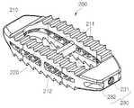
- FIG. 4A perspective view of a cage according to an embodiment of the present invention.
- FIG. 5A perspective view of a cage according to another embodiment of the present invention.
- Figure 6A schematic diagram showing a state in which the cage is coupled to the guider for spinal surgery according to an embodiment of the present invention is inserted.
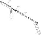
- Figure 7 -A schematic diagram showing a surgical situation in which a holder coupled to a cage is guided to a guider for spine surgery according to an embodiment of the present invention.
- the present inventionrelates to a guider for spine surgery that is inserted into an incision of the human body for spinal surgery and guides a holder to which a cage for spinal surgery is coupled to a surgical site. This is to ensure a smooth surgical process.
- the cage guided by the guider for spine surgery according to the present inventionis formed in a wider shape to fit the treatment site, preventing side effects due to subsidence phenomenon, and has the advantage of high fusion rate.
- the cage according to the present inventionis operated by approaching posteriorly, there is less burden during surgery than when approaching anteriorly, where there are many major blood vessels. This makes it easy to adjust the position and direction of the cage.
- the cage according to the present inventionhas the advantage of easy operation because the cage can be inserted from the rear and the screw for spinal correction can be inserted from the rear.
- Figure 1is a perspective view of a guider for spinal surgery according to an embodiment of the present invention
- Figure 2is a perspective view of a guider for spinal surgery according to another embodiment of the present invention
- FIG. 5is a perspective view of a cage according to another embodiment of the present invention
- FIG. 6is a perspective view of the present invention It is a schematic diagram showing a state in which the holder coupled to the cage is inserted into the guider for spine surgery according to an embodiment of the present invention
- FIG.It is a schematic diagram showing the situation.
- the head 114is inserted into the incision of the human body for spinal surgery, and the holder 300 to which the cage 200 for spinal surgery is coupled is inserted.
- a sliding part 110 that guides the cage 200 and the holder 300 to the surgical site, and a support 120 coupled to one side of the sliding part 110 and supporting the sliding part 110 andis largely composed of a handle unit 130 coupled to the support 120 .
- the guider 100 for spine surgeryis inserted into an incision of the human body for spinal surgery to guide the holder 300 to which the cage for spine surgery 200 is coupled to the surgical site, the cage 200 This is to prevent tissue damage in the incision during the insertion process to ensure a smooth surgical procedure.
- the guider 100 for spine surgeryhas a sliding unit 110 as a main component, and the sliding unit 110 includes a head 114 inserted into an incision of a human body for spine surgery, and is used for spinal surgery.
- the cage 200is coupled to the holder 300 is inserted to guide the cage 200 and the holder 300 to the surgical site.
- the sliding unit 110serves to protect the tissue of the incision from being damaged even when the head 114 is inserted into the incision and the cage 200 and the holder 300 are inserted into the incision.
- the wide-type cage (200)can be usefully applied.
- the sliding unit 110is formed with a length that is long enough to stably guide the cage 200 and the holder 300 to the surgical site by inserting the head 114 into the incision, and the head 114 is It is formed narrower toward the front to facilitate insertion into the incision.
- the sliding part 110is provided with an elastic force so that the size of the space part 113 can be flexibly adjusted according to the shape of the surgical site or incision to be applied, and the shape of the cage 200 and the holder 300 . It is preferable to form
- the sliding part 110is formed to a predetermined length, a space 113 is formed therein so that the cage 200 and the holder 300 can move, and the cutout is formed.
- the front sideis formed narrow to facilitate insertion of the cage 200 and the holder 300 to the rear side is formed in a structure that can be inserted.
- the sliding part 110may be integrally formed as a whole so that the cage 200 and the holder 300 can be guided. It is preferable to be formed so as to be possible.
- the first slider 111 and the second slider 112are separated and formed to face each other and spaced apart so that the space portion 113 is provided. do.
- the holder 300 to which the cage 200 is coupledis inserted through the space 113 .
- a head 114is provided in front of the first slider 111 and the second slider 112 to be inserted into an incision for spinal surgery as described above, and the head 114 is inserted into the incision.
- one side of the first slider 111 and the second slideis formed to be bent so that the space portion 113 is narrowed.
- the guider 100 for spine surgeryis formed on the upper side of the first slider 111 and the second slider 112, and the first slider 111 so that the space part 113 is narrowed. ) and an upper guide 115 in which an upper side of the second slider 112 is bent.
- first slider 111 and the second slider 112are formed below the first slider 111 and the second slider 112, and the lower side of the first slider 111 and the second slider 112 are bent so that the space portion 113 is narrowed.
- a lower guide 116is provided.
- the upper guide 115 and the lower guide 116are to prevent separation of the cage 200 and the holder 300 inserted into the space 113, and the first slider 111 and the second slider Since the 112 is formed separately, the upper guide 115 and the lower guide 116 are respectively formed.
- the opposing upper guide 115 and the opposing lower guide 116are formed to be spaced apart from each other by a predetermined interval to provide a gap according to the elastic flow of the space portion 113 .
- the support 120is coupled to one side of the sliding unit 110 , and supports the sliding unit 110 , and is formed at a predetermined angle so as not to interfere with the sliding unit 110 .
- the support 120is coupled to the rear side of the first slider 111 and the second slider 112, is formed in a Y-shape, the upper end of the Y-shape and the first slider ( 111) and the second slider 112 are coupled to each other.
- the Y-shaped lower endis formed to be separated into the first slider 111 side and the second slider 112 side.
- the sliding unit 110 and the support 120 according to the present inventionare formed in a configuration separated to the left and right. This is to provide an elastic force so that the size of the space 113 can be flexibly adjusted according to the shape of the surgical site or incision to be applied, and the shape of the cage 200 and holder 300 as described above.
- the support 120is formed to surround the rear of the first slider 111 and the second slider 112, and the support 120 and the first slider 111 and the second slider 112. while maintaining a stable bonding state, the elastic force can be transmitted better.
- the support 120may further have an elastic sphere 121 formed on one side, which is to impart elasticity to the space 113 as described above. .
- the handle 130is coupled to the support 120, for the convenience of the user.
- the handle unit 130is coupled to the distal end of the support 120 , and may be coupled in a manner such as screw coupling or welding, and is coupled in the same direction as the support 120 .
- the handle unit 130is formed in a cylindrical shape as a whole, and the outer peripheral surface thereof may be formed in a polyhedral shape for unevenness or direction indication.
- the guide for spine surgeryis inserted into the incision of the human body during spinal surgery to guide the holder to which the cage for spinal surgery is coupled to the surgical site, and the tissue of the incised area during the cage insertion process during spinal surgery This is to prevent damage to ensure smooth operation.
- the cage 200 for spine surgery according to the present inventionis guided by the guider 100 for spine surgery.
- the front and rear of the body 210formed in a streamlined shape, the directional protrusions 220 formed on the upper and lower surfaces of the main body 210, and the main body 210 of It is formed on the rear side, and is formed to include a coupling part 230 to which the holder 300 is coupled.
- the cage 200 guided by the guider 100 for spinal surgery according to the present inventionis formed in a wide shape to fit the treatment site, which prevents side effects due to the subsidence phenomenon, and the fusion rate ( Fusion rate) is high.
- the wide typemeans that the width in the width direction of the main body 210 is 1/2 to 1 times the width in the length direction.
- the cage 200 according to the present inventionmay be formed of titanium or PEEK material having a high human affinity and a high coalescence rate.
- the front and rear of the body 210are formed in a streamlined shape to prevent damage to nerves or muscle tissue during insertion of the intervertebral body, facilitate insertion of the intervertebral body, and advantageously change direction.
- the main body 210may include a window 211 penetrating vertically, a window 211 penetrating left and right, or a window 211 penetrating vertically and horizontally.
- the window 211may be filled with bone chips or bone cement, such as artificial bone or autogenous bone, to improve the fusion rate due to bone growth from adjacent vertebral bodies.
- bone chips or bone cementsuch as artificial bone or autogenous bone
- These windows 211may be formed in single or plural in consideration of the shape of the vertebral body and the fusion rate according to lesions.
- one aspect of the present inventionmay be formed in a mesh shape, which is stably positioned between the vertebral bodies, and enables rapid tissue regeneration to increase the fusion rate.
- FIG. 4shows that one side of the body 210 is formed in a mesh shape, and windows 211 penetrating vertically are formed, and FIG. 5 shows that windows 211 are formed on the top and bottom, left and right. It is designed in consideration of the fusion rate according to the shape and lesion of the vertebral body.
- the directional protrusion 220is preferably formed on the upper and lower surfaces of the main body 210 so that the cage 200 is stably fixed between the vertebral bodies, and the fusion rate is increased.
- the directional protrusion 220has a face (front) in the direction of progression to the surgical site at a low angle, and the opposite face (rear) at a higher angle to facilitate the operation, and within the intervertebral body. It prevents unauthorized movement.
- the coupling part 230is formed on the rear side of the main body 210 , and the holder 300 is coupled, and the screw part 231 to which the holder 300 is coupled, and the screw part 231 both sides. It is formed to include a coupler 232 formed in the holder 300 so that the stable coupling is made.
- the coupler 232may be formed according to a lesion situation or a surgical site, and is coupled by a holder 300 or a separate instrument to facilitate insertion and positioning of the cage 200 .
- FIG. 6shows a state in which the cage 200 is coupled to the holder 300 is inserted into the guider 100 for spinal surgery according to an embodiment of the present invention
- FIG. 7is a spine according to an embodiment of the present invention. It shows a surgical situation in which the holder 300 in which the cage 200 is coupled to the surgical guider 100 is guided. By minimizing and stably inserting the cage 200 between the vertebral bodies, the surgical procedure is performed smoothly.
- the cage according to the present inventionis guided by the guider for spinal surgery together with the holder, and is inserted between the vertebral bodies without damage to the tissue surrounding the incision.
- the cage according to the present inventionis operated by approaching posteriorly, there is less burden during surgery than when approaching anteriorly, where there are many major blood vessels. This makes it easy to adjust the position and direction of the cage.
- the cage according to the present inventionhas the advantage of easy operation because the cage can be inserted from the rear and the screw for spinal correction can be inserted from the rear.
Landscapes
- Health & Medical Sciences (AREA)
- Engineering & Computer Science (AREA)
- Biomedical Technology (AREA)
- Orthopedic Medicine & Surgery (AREA)
- Neurology (AREA)
- Transplantation (AREA)
- Life Sciences & Earth Sciences (AREA)
- Animal Behavior & Ethology (AREA)
- Veterinary Medicine (AREA)
- Public Health (AREA)
- General Health & Medical Sciences (AREA)
- Oral & Maxillofacial Surgery (AREA)
- Heart & Thoracic Surgery (AREA)
- Cardiology (AREA)
- Vascular Medicine (AREA)
- Chemical & Material Sciences (AREA)
- Physical Education & Sports Medicine (AREA)
- Dermatology (AREA)
- Epidemiology (AREA)
- Surgery (AREA)
- Medicinal Chemistry (AREA)
- Medical Informatics (AREA)
- Inorganic Chemistry (AREA)
- Molecular Biology (AREA)
- Nuclear Medicine, Radiotherapy & Molecular Imaging (AREA)
- Surgical Instruments (AREA)
- Prostheses (AREA)
Abstract
Description
Translated fromKorean본 발명은 척추 수술용 가이더 및 이를 위한 척추 수술용 케이지에 관한 것으로서, 척추 수술을 위한 인체의 절개부에 삽입되어 척추 수술용 케이지가 결합된 홀더를 수술부위까지 안내하는 척추 수술용 가이더와, 상기 척추 수술용 가이더에 의해 안내되는 와이드형 케이지에 관한 것이다.The present invention relates to a guider for spinal surgery and a cage for spinal surgery therefor, comprising: a guider for spinal surgery that is inserted into an incision of a human body for spinal surgery and guides a holder to which the cage for spinal surgery is coupled to a surgical site; It relates to a wide cage guided by a guide for spine surgery.
본 발명을 지원한 국가연구개발사업은 다음과 같다:The national R&D projects supporting the present invention are as follows:
과제고유번호 1415166420Assignment identification number 1415166420
과제번호 P0006714Assignment number P0006714
부처명 산업통상자원부Department name Ministry of Trade, Industry and Energy
연구관리전문기관 한국산업기술진흥원Research and management institution Korea Institute of Industrial Technology Promotion
연구사업명 국가혁신클러스터사업Research project name National Innovation Cluster Project
연구과제명 3D 영상 재구성과 생체 신호를 이용한 지능형Research project name 3D image reconstruction and intelligent using biosignals
맞춤 수술 플래닝 및 술후 케어 솔루션 개발Development of customized surgical planning and postoperative care solutions
기여율 100
주관기관(주)엔도비전Organized by Endovision Co., Ltd.
연구기간2018.10.1.~2020.12.31Research period 2018.10.1.~2020.12.31
일반적으로 척추는 통상 24개(천추골 제외)의 뼈로 이루어져 있으며, 이것은 관절 마디로 연결되어 있고, 각 관절의 사이에는 인체가 움직이거나 관절이 작동할때마다 그에 따른 충격을 흡수하고, 하중을 지지하기 위한 디스크가 위치하고 있다.In general, the spine usually consists of 24 bones (excluding the sacrum), which are connected by joint nodes, and between each joint, whenever the human body moves or the joint operates, it absorbs the shock and supports the load. There is a disk for that.
이러한 구성에 의해 척추는 완충작용을 하면서 인간의 자세를 지탱해 줄 뿐만 아니라, 운동의 토대가 되면 내장의 모든 기관을 보호하는 중요한 기능을 한다.By this configuration, the spine not only supports human posture while acting as a buffer, but also plays an important role in protecting all organs of the internal organs when it becomes the basis of movement.
그러나 척추가 외부의 인위적인 요인, 퇴행성 또는 비정상적인 자세가 오랫동안 지속됨에 따라 척추가 손상되거나 틀어진 경우 척추관을 통과하는 신경을 압박함으로써 심한 통증을 유발하게 된다.However, if the spine is damaged or distorted due to external artificial factors, degenerative or abnormal postures for a long time, it causes severe pain by compressing the nerves passing through the spinal canal.
즉, 척추의 일부가 손상된 환자는 개인생활에 필요한 활동을 할 수 없고, 손상 정도가 심하지 않은 경우에도 척추의 손상된 부분이 다른 인접한 부분에 눌려지거나 닿게 되어 통증을 유발하게 된다.That is, a patient with a part of the spine damaged cannot perform activities necessary for personal life, and even if the degree of damage is not severe, the damaged part of the spine is pressed or touched to another adjacent part, causing pain.
이러한 척추 질환의 수술적 치료 방법 중의 하나로 유합술(fusion)에 이용되는 추간체 유합 케이지는 요추의 척추뼈 이식 또는 척추이탈 및 만곡증의 고정술을 돕기 위해 손상된 디스크를 제거한 후 척추체 사이에 시술되는 임플란트의 일종이다.The intervertebral fusion cage used for fusion as one of the surgical treatment methods for these spinal diseases is a type of implant that is operated between the vertebrae after removing the damaged disc to help with lumbar vertebra transplantation or fixation of vertebral dislocation and curvature. to be.
종래의 케이지는 시술 부위에 비해 싸이즈가 작아 부작용으로 침강(Subsidence) 현상이 발생하고 있으며, 융합율(Fusion rate)이 낮은 단점이 있다.The conventional cage has a small size compared to the treatment site, which causes subsidence as a side effect, and has a disadvantage in that the fusion rate is low.
또한 기존 케이지는 전방(anterior)으로 접근해서 시술이 이루어지므로 주요 혈관이 많아 수술시 부담감이 많으며, 전방 접근 시 홀더를 이용하여 척추체 간에 케이지를 삽입시키고 이를 회전시켜 케이지의 위치와 방향을 조절하면서 시술하게 된다.In addition, the existing cage approaches anteriorly, so there are a lot of major blood vessels, so there is a lot of pressure during surgery. will do
이러한 케이지 삽입과정에서 절개된 부위의 조직에 손상을 줄 수 있으며, 시술과정에서 조직의 절개부의 형태가 변형되어 수술 과정이 어려워질 수 있으며, 이에 의해 제대로 된 시술이 이루어지지 않을 염려가 있다.In the cage insertion process, the tissue of the incised area may be damaged, and the shape of the incision of the tissue may be deformed during the procedure, which may make the surgical process difficult, and thereby there is a fear that the proper operation may not be performed.
그리고, 전방에서 케이지를 삽입하고 후방에서 척추 교정용 스크류를 삽입해야 하므로, 수술이 어렵고 숙련된 수술의만이 성공적인 수술이 가능한 것으로 알려져 있다.And, since it is necessary to insert a cage from the front and a screw for spinal correction from the rear, it is known that surgery is difficult and only a skilled surgeon can perform a successful operation.
본 발명은 상기 필요성에 의해 고안된 것으로서, 척추 수술을 위한 인체의 절개부에 삽입되어 척추 수술용 케이지가 결합된 홀더를 수술부위까지 안내하는 척추 수술용 가이더와, 상기 척추 수술용 가이더에 의해 안내되는 와이드형 케이지의 제공을 그 목적으로 한다.The present invention was devised by the above necessity, and is inserted into an incision of the human body for spinal surgery and guides a holder coupled with a cage for spinal surgery to a surgical site, and a guide for spinal surgery guided by the guider The purpose is to provide a wide-type cage.
상기 목적 달성을 위해 본 발명은, 척추 수술을 위한 인체의 절개부에 헤드가 삽입되고, 척추 수술용 케이지가 결합된 홀더가 삽입되어 상기 케이지와 홀더를 수술부위까지 안내하는 슬라이딩부와, 상기 슬라이딩부의 일측에 결합되고, 상기 슬라이딩부를 지지하는 지지대와, 상기 지지대와 결합되는 핸들부를 포함하는 것을 특징으로 하는 척추 수술용 가이더를 기술적 요지로 한다.In order to achieve the above object, the present invention includes a sliding unit in which a head is inserted into an incision of a human body for spine surgery, a holder coupled with a cage for spine surgery is inserted, and guides the cage and the holder to the surgical site, and the sliding Coupled to one side of the portion, and a support for supporting the sliding portion, and a guide for spine surgery, characterized in that it comprises a handle portion coupled to the support as a technical gist.
또한, 상기 슬라이딩부는, 제1슬라이더 및 제2슬라이더가 상호 대향되면서 이격되게 형성되어 공간부를 마련하며, 상기 공간부로 상기 케이지가 결합된 홀더가 삽입되는 것이 바람직하다.In addition, it is preferable that the sliding part is formed to be spaced apart while the first slider and the second slider are opposed to each other to provide a space, and a holder to which the cage is coupled is inserted into the space.
또한, 상기 제1슬라이더 및 상기 제2슬라이더 전방에 형성되며, 상기 공간부가 좁혀지도록 상기 제1슬라이더 및 상기 제2슬라이더 일측이 절곡되게 형성된 헤드가 구비되는 것이 바람직하다.In addition, it is preferable that a head formed in front of the first slider and the second slider is formed such that one side of the first slider and the second slider are bent to narrow the space.
또한, 상기 제1슬라이더 및 상기 제2슬라이더 상측에 형성되며, 상기 공간부가 좁혀지도록 상기 제1슬라이더 및 상기 제2슬라이더의 상측이 절곡되게 형성된 상측 가이드가 구비되는 것이 바람직하다.In addition, it is preferable that an upper guide formed above the first slider and the second slider is formed so that the upper side of the first slider and the second slider are bent to narrow the space.
또한, 상기 제1슬라이더 및 상기 제2슬라이더 하측에 형성되며, 상기 공간부가 좁혀지도록 상기 제1슬라이더 및 상기 제2슬라이더 하측이 절곡되게 형성된 하측 가이드가 구비되는 것이 바람직하다.In addition, it is preferable that a lower guide formed below the first and second sliders and bent under the first and second sliders to narrow the space is provided.
또한, 상기 지지대는, 상기 제1슬라이더 및 제2슬라이더 후방측에 결합되며, Y자형으로 형성되어, 상기 Y자형의 상단부와 상기 제1슬라이더 및 제2슬라이더가 각각 결합되는 것이 바람직하다.In addition, it is preferable that the support is coupled to the rear side of the first slider and the second slider, and is formed in a Y-shape, so that the upper end of the Y-shape and the first slider and the second slider are coupled to each other.
또한, 상기 지지대는, 상기 Y자형의 하단부가 상기 제1슬라이더 측 및 제2슬라이더 측으로 분리되게 형성되는 것이 바람직하며, 상기 지지대는, 상기 제1슬라이더 및 제2슬라이더 후방을 감싸도록 형성될 수 있으며, 상기 지지대는, 일측에 탄성구가 더 형성되는 것이 바람직하다.In addition, the support is preferably formed so that the lower end of the Y-shape is separated into the first slider side and the second slider side, and the support is formed to surround the rear of the first slider and the second slider, , It is preferable that the support is further formed with an elastic sphere on one side.
한편 본 발명은, 상기 척추 수술용 가이더에 의해 안내되는 것을 특징으로 하는 케이지를 제공하는 것으로 기술적 요지로 하며, 상기 케이지는, 전방 및 후방이 유선형으로 형성된 본체와, 상기 본체 상면 및 하면에 형성된 방향성 돌기와, 상기 본체의 후방측에 형성되며, 상기 홀더가 결합되는 결합부를 포함하여 형성되는 것이 바람직하다.On the other hand, the present invention is a technical gist of the present invention to provide a cage, characterized in that guided by the guide for spine surgery, the cage, the front and rear are formed in a streamlined body, and the directionality formed on the upper and lower surfaces of the main body It is preferably formed including a protrusion and a coupling portion formed on the rear side of the main body to which the holder is coupled.
또한 상기 본체의 일측면은, 메쉬형으로 형성될 수 있다.In addition, one side of the body may be formed in a mesh shape.
또한, 상기 본체는, 상하로 관통되는 윈도우 또는 좌우로 관통되는 윈도우가 형성되거나, 상하 및 좌우로 관통되는 윈도우가 형성된 것이 바람직하다.In addition, it is preferable that the main body has a window penetrating vertically or a window penetrating left and right, or a window penetrating vertically and horizontally.
또한, 상기 윈도우는, 격벽에 의해 구분되어 복수개로 형성된 것이 바람직하다.In addition, it is preferable that the window is divided by a partition and formed in plurality.
또한, 상기 결합부는, 홀더가 결합되는 나사부와, 상기 나사부 양측에 형성된 결합구를 포함하는 것이 바람직하다.In addition, the coupling portion, it is preferable to include a screw portion to which the holder is coupled, and a coupling hole formed on both sides of the screw portion.
또한, 상기 본체의 폭 방향의 너비는, 길이방향의 너비에 대해 1/2 ~ 1배로 형성된 것이 바람직하다.In addition, the width in the width direction of the body is preferably formed to be 1/2 to 1 times the width in the longitudinal direction.
또한, 상기 케이지는, 척추체의 후방(anterior)으로 접근해서 척추체 간에 삽입될 수 있으며, 상기 케이지는, 티타늄 또는 PEEK 소재로 형성되는 것이 바람직하다.In addition, the cage may be inserted between the vertebral bodies by approaching the back (anterior) of the vertebral body, and the cage is preferably made of titanium or PEEK material.
본 발명은 척추 수술을 위한 인체의 절개부에 삽입되어 척추 수술용 케이지가 결합된 홀더를 수술부위까지 안내하는 척추 수술용 가이더에 관한 것으로서, 척추 수술시 케이지 삽입과정에서 절개된 부위의 조직 손상을 방지하여 원활한 수술 과정이 이루어지도록 하는 효과가 있다.The present invention relates to a guider for spine surgery that is inserted into an incision of the human body for spinal surgery and guides a holder to which a cage for spinal surgery is coupled to a surgical site. This has the effect of preventing a smooth surgical process.
또한 본 발명에 따른 척추 수술용 가이더에 의해 안내되는 케이지는 시술 부위에 비해 맞게 와이드형으로 형성되어, 침강(Subsidence) 현상에 따른 부작용을 방지하고, 융합율(Fusion rate)이 높은 장점이 있다.In addition, the cage guided by the guider for spine surgery according to the present invention is formed in a wider shape to fit the treatment site, preventing side effects due to subsidence phenomenon, and has the advantage of high fusion rate.
또한 본 발명에 따른 케이지는 후방(posterior)으로 접근해서 시술이 이루어지므로 주요 혈관이 많은 전방(anterior) 접근시보다 수술시 부담감이 적으며, 후방 접근 시 홀더에 의해 척추체 간에 케이지를 삽입시키고 이를 회전시켜 케이지의 위치와 방향의 조절이 용이하다.In addition, since the cage according to the present invention is operated by approaching posteriorly, there is less burden during surgery than when approaching anteriorly, where there are many major blood vessels. This makes it easy to adjust the position and direction of the cage.
또한 본 발명에 따른 케이지는 후방에서 케이지를 삽입하고 후방에서 척추 교정용 스크류를 삽입할 수 있으므로, 수술이 용이한 장점이 있다.In addition, the cage according to the present invention has the advantage of easy operation because the cage can be inserted from the rear and the screw for spinal correction can be inserted from the rear.
도 1 - 본 발명의 일실시예에 따른 척추 수술용 가이더에 대한 사시도.1 - A perspective view of a guider for spine surgery according to an embodiment of the present invention.
도 2 - 본 발명의 다른 실시예에 따른 척추 수술용 가이더에 대한 사시도.Figure 2 - A perspective view of a guider for spine surgery according to another embodiment of the present invention.
도 3 - 본 발명의 다른 실시예에 따른 척추 수술용 가이더에 대한 저면 사시도.Figure 3 - A bottom perspective view of a guider for spine surgery according to another embodiment of the present invention.
도 4 - 본 발명의 일실시예에 따른 케이지에 대한 사시도.4 - A perspective view of a cage according to an embodiment of the present invention.
도 5 - 본 발명의 다른 실시예에 따른 케이지에 대한 사시도.5 - A perspective view of a cage according to another embodiment of the present invention.
도 6 - 본 발명의 일실시예에 따른 척추 수술용 가이더에 케이지가 결합된 홀더가 삽입되는 상태를 나타낸 모식도.Figure 6 - A schematic diagram showing a state in which the cage is coupled to the guider for spinal surgery according to an embodiment of the present invention is inserted.
도 7 - 본 발명의 일실시예에 따른 척추 수술용 가이더에 케이지가 결합된 홀더가 안내되는 수술 상황을 나타낸 모식도.Figure 7 - A schematic diagram showing a surgical situation in which a holder coupled to a cage is guided to a guider for spine surgery according to an embodiment of the present invention.
본 발명은 척추 수술을 위한 인체의 절개부에 삽입되어 척추 수술용 케이지가 결합된 홀더를 수술부위까지 안내하는 척추 수술용 가이더에 관한 것으로서, 척추 수술시 케이지 삽입과정에서 절개된 부위의 조직 손상을 방지하여 원활한 수술 과정이 이루어지도록 하는 것이다.The present invention relates to a guider for spine surgery that is inserted into an incision of the human body for spinal surgery and guides a holder to which a cage for spinal surgery is coupled to a surgical site. This is to ensure a smooth surgical process.
또한 본 발명에 따른 척추 수술용 가이더에 의해 안내되는 케이지는 시술 부위에 비해 맞게 와이드형으로 형성되어, 침강(Subsidence) 현상에 따른 부작용을 방지하고, 융합율(Fusion rate)이 높은 장점이 있다.In addition, the cage guided by the guider for spine surgery according to the present invention is formed in a wider shape to fit the treatment site, preventing side effects due to subsidence phenomenon, and has the advantage of high fusion rate.
또한 본 발명에 따른 케이지는 후방(posterior)으로 접근해서 시술이 이루어지므로 주요 혈관이 많은 전방(anterior) 접근시보다 수술시 부담감이 적으며, 후방 접근 시 홀더에 의해 척추체 간에 케이지를 삽입시키고 이를 회전시켜 케이지의 위치와 방향의 조절이 용이하다.In addition, since the cage according to the present invention is operated by approaching posteriorly, there is less burden during surgery than when approaching anteriorly, where there are many major blood vessels. This makes it easy to adjust the position and direction of the cage.
또한 본 발명에 따른 케이지는 후방에서 케이지를 삽입하고 후방에서 척추 교정용 스크류를 삽입할 수 있으므로, 수술이 용이한 장점이 있다.In addition, the cage according to the present invention has the advantage of easy operation because the cage can be inserted from the rear and the screw for spinal correction can be inserted from the rear.
이하에서는 첨부된 도면을 참조하여 본 발명에 대해 설명하고자 한다. 도 1은 본 발명의 일실시예에 따른 척추 수술용 가이더에 대한 사시도이고, 도 2는 본 발명의 다른 실시예에 따른 척추 수술용 가이더에 대한 사시도이고, 도 3은 본 발명의 다른 실시예에 따른 척추 수술용 가이더에 대한 저면 사시도이고, 도 4는 본 발명의 일실시예에 따른 케이지에 대한 사시도이고, 도 5는 본 발명의 다른 실시예에 따른 케이지에 대한 사시도이고, 도 6은 본 발명의 일실시예에 따른 척추 수술용 가이더에 케이지가 결합된 홀더가 삽입되는 상태를 나타낸 모식도이고, 도 7은 본 발명의 일실시예에 따른 척추 수술용 가이더에 케이지가 결합된 홀더가 안내되는 수술 상황을 나타낸 모식도이다.Hereinafter, the present invention will be described with reference to the accompanying drawings. Figure 1 is a perspective view of a guider for spinal surgery according to an embodiment of the present invention, Figure 2 is a perspective view of a guider for spinal surgery according to another embodiment of the present invention, Figure 3 is another embodiment of the present invention 4 is a perspective view of a cage according to an embodiment of the present invention, FIG. 5 is a perspective view of a cage according to another embodiment of the present invention, and FIG. 6 is a perspective view of the present invention It is a schematic diagram showing a state in which the holder coupled to the cage is inserted into the guider for spine surgery according to an embodiment of the present invention, and FIG. It is a schematic diagram showing the situation.
도시된 바와 같이 본 발명에 따른 척추 수술용 가이더(100)는, 척추 수술을 위한 인체의 절개부에 헤드(114)가 삽입되고, 척추 수술용 케이지(200)가 결합된 홀더(300)가 삽입되어 상기 케이지(200)와 홀더(300)를 수술부위까지 안내하는 슬라이딩부(110)와, 상기 슬라이딩부(110)의 일측에 결합되고, 상기 슬라이딩부(110)를 지지하는 지지대(120)와, 상기 지지대(120)와 결합되는 핸들부(130)로 크게 구성된다.As shown, in the
본 발명에 따른 척추 수술용 가이더(100)는, 척추 수술을 위한 인체의 절개부에 삽입되어 척추 수술용 케이지(200)가 결합된 홀더(300)를 수술부위까지 안내하는 것으로서, 케이지(200) 삽입과정에서 상기 절개부의 조직 손상을 방지하여 원활한 수술 과정이 이루어지도록 하는 것이다.The
본 발명에 따른 척추 수술용 가이더(100)는 슬라이딩부(110)를 주요 구성으로 하며, 상기 슬라이딩부(110)는 척추 수술을 위한 인체의 절개부에 헤드(114)가 삽입되고, 척추 수술용 케이지(200)가 결합된 홀더(300)가 삽입되어 상기 케이지(200)와 홀더(300)를 수술부위까지 안내하는 것이다.The
상기 슬라이딩부(110)는 절개부에 헤드(114)가 삽입되어 케이지(200) 및 홀더(300)가 절개부에 삽입되더라도 절개부의 조직이 손상되지 않도록 보호하는 역할을 하는 것으로서, 특히 와이드형 케이지(200)에 유용하게 적용될 수 있다.The sliding
상기 슬라이딩부(110)는 절개부에 헤드(114)가 삽입되어, 케이지(200) 및 홀더(300)를 수술부위까지 안정적으로 안내할 수 있을 정도의 길이로 형성되며, 상기 헤드(114)는 절개부에의 삽입이 용이하도록 전방으로 갈수록 좁게 형성된다.The sliding
그리고 상기 슬라이딩부(110)는 케이지(200) 및 홀더(300)가 삽입되어 안내되어야 하므로 내부에 케이지(200) 및 홀더(300)가 원활히 이동할 수 있을 정도의 공간부(113)가 형성되게 된다.In addition, since the sliding
또한 상기 슬라이딩부(110)는 적용하고자 하는 수술 부위나 절개부의 형태, 케이지(200) 및 홀더(300)의 형태에 따라 상기 공간부(113)의 크기가 유동적으로 조절될 수 있도록 탄성력이 부여되도록 형성되는 것이 바람직하다.In addition, the sliding
즉, 본 발명의 일실시예에 따른 슬라이딩부(110)는 소정의 길이로 형성되며, 내부에 케이지(200) 및 홀더(300)가 이동할 수 있도록 공간부(113)가 형성되고, 절개부에의 삽입이 용이하도록 전방측은 좁게 형성되며, 후방측으로 케이지(200) 및 홀더(300)가 삽입될 수 있는 구조로 형성된 것이다.That is, the sliding
상기 슬라이딩부(110)는 상기 케이지(200) 및 홀더(300)가 안내될 수 있도록 전체적으로 일체로 형성될 수도 있으나, 상술한 바와 같이 일정 힘으로 탄성력에 의해 상기 공간부(113)의 크기가 유동되도록 형성되는 것이 바람직하다.The sliding
구체적으로는, 도 1 내지 도 3에 도시한 바와 같이, 제1슬라이더(111) 및 제2슬라이더(112)로 분리되어 형성되며, 상호 대향되면서 이격되게 형성되어 공간부(113)가 마련되도록 형성된다. 상기 공간부(113)를 통해 상기 케이지(200)가 결합된 홀더(300)가 삽입되게 된다.Specifically, as shown in FIGS. 1 to 3 , the
상기 제1슬라이더(111) 및 상기 제2슬라이더(112) 전방에는 상술한 바와 같이 척추 수술을 위한 절개부로 삽입되는 것으로 헤드(114)가 구비되며, 상기 헤드(114)는 상기 절개부에의 삽입이 용이하도록 상기 공간부(113)가 좁혀지도록 상기 제1슬라이더(111) 및 상기 제2슬라이드 일측이 절곡되게 형성된다.A
또한, 본 발명에 따른 척추 수술용 가이더(100)는, 상기 제1슬라이더(111) 및 상기 제2슬라이더(112) 상측에 형성되며, 상기 공간부(113)가 좁혀지도록 상기 제1슬라이더(111) 및 상기 제2슬라이더(112)의 상측이 절곡되게 형성된 상측 가이드(115)가 구비된다.In addition, the
또한 상기 제1슬라이더(111) 및 상기 제2슬라이더(112) 하측에 형성되며, 상기 공간부(113)가 좁혀지도록 상기 제1슬라이더(111) 및 상기 제2슬라이더(112) 하측이 절곡되게 형성된 하측 가이드(116)가 구비된다.In addition, the
상기 상측 가이드(115) 및 하측 가이드(116)는 상기 공간부(113) 내로 삽입되는 케이지(200) 및 홀더(300)의 이탈을 방지하기 위한 것으로, 상기 제1슬라이더(111) 및 제2슬라이더(112)가 각각 분리되게 형성되므로 상기 상측 가이드(115) 및 하측 가이드(116)는 각각 형성되게 된다.The
이때 각 대향되는 상측 가이드(115) 및 각 대향되는 하측 가이드(116)는 상기 공간부(113)의 탄성 유동에 따라 유격을 주기 위해 소정 간격으로 이격되게 형성된다.In this case, the opposing
그리고, 상기 지지대(120)는 상기 슬라이딩부(110)의 일측에 결합되고, 상기 슬라이딩부(110)를 지지하는 것으로, 상기 슬라이딩부(110)와 간섭이 일어나지 않도록 소정 각도로 형성된다.In addition, the
본 발명의 일실시예로는 상기 지지대(120)는 상기 제1슬라이더(111) 및 제2슬라이더(112) 후방측에 결합되며, Y자형으로 형성되어 상기 Y자형의 상단부와 상기 제1슬라이더(111) 및 제2슬라이더(112)가 각각 결합되게 된다.In one embodiment of the present invention, the
또한, 상기 Y자형의 하단부가 상기 제1슬라이더(111) 측 및 제2슬라이더(112) 측으로 분리되게 형성된다.In addition, the Y-shaped lower end is formed to be separated into the
즉, 본 발명에 따른 슬라이딩부(110) 및 지지대(120)는 좌우측으로 분리된 구성으로 형성되는 것이 바람직하다. 이는 상술한 바와 같이 적용하고자 하는 수술 부위나 절개부의 형태, 케이지(200) 및 홀더(300)의 형태에 따라 상기 공간부(113)의 크기가 유동적으로 조절될 수 있도록 탄성력을 부여하기 위한 것이다.That is, it is preferable that the sliding
또한, 상기 지지대(120)는, 상기 제1슬라이더(111) 및 제2슬라이더(112) 후방을 감싸도록 형성되어, 상기 지지대(120)와 상기 제1슬라이더(111) 및 제2슬라이더(112)가 안정적인 결합상태를 유지하도록 하면서, 상기 탄성력이 더욱 더 잘 전달될 수 있도록 한다.In addition, the
또한, 도 2 및 도 3에 도시한 바와 같이 상기 지지대(120)는 일측에 탄성구(121)가 더 형성될 수 있으며, 이는 상술한 바와 같이 상기 공간부(113)에 탄성을 부여하기 위한 것이다.In addition, as shown in FIGS. 2 and 3 , the
그리고 상기 핸들부(130)는 상기 지지대(120)와 결합되는 것으로, 사용자의 사용의 편의를 위한 것이다.And the
상기 핸들부(130)는 상기 지지대(120)의 말단부와 결합되는 것으로 나사결합 또는 용접결합 등의 방식으로 결합될 수 있으며, 상기 지지대(120)와 동일한 방향으로 결합된다.The
상기 핸들부(130)는 전체적으로 원통형으로 형성되되, 그 외주면에는 요철이나 방향 표시를 위해 다면체 형태로 형성될 수 있다.The
이에 의해 본 발명에 따른 척추 수술용 가이더는, 척추 수술 시 인체의 절개부에 삽입되어 척추 수술용 케이지가 결합된 홀더를 수술부위까지 안내하는 것으로서, 척추 수술시 케이지 삽입과정에서 절개된 부위의 조직 손상을 방지하여 원활한 수술이 이루어지도록 하는 것이다.Accordingly, the guide for spine surgery according to the present invention is inserted into the incision of the human body during spinal surgery to guide the holder to which the cage for spinal surgery is coupled to the surgical site, and the tissue of the incised area during the cage insertion process during spinal surgery This is to prevent damage to ensure smooth operation.
한편, 본 발명에 따른 척추 수술용 케이지(200)는 상기 척추 수술용 가이더(100)에 의해 안내되게 된다.On the other hand, the
본 발명의 일실시예에 따른 케이지(200)는, 전방 및 후방이 유선형으로 형성된 본체(210)와, 상기 본체(210) 상면 및 하면에 형성된 방향성 돌기(220)와, 상기 본체(210)의 후방측에 형성되며, 상기 홀더(300)가 결합되는 결합부(230)를 포함하여 형성된다.
또한 본 발명에 따른 척추 수술용 가이더(100)에 의해 안내되는 케이지(200)는 시술 부위에 비해 맞게 와이드형으로 형성되는 것이 바람직하며, 이는 침강(Subsidence) 현상에 따른 부작용을 방지하고, 유합율(Fusion rate)이 높은 장점이 있다.In addition, it is preferable that the
본 발명에서 와이드형이라 함은 상기 본체(210)의 폭 방향의 너비가 길이방향의 너비에 대해 1/2 ~ 1배로 형성되는 것을 의미한다.In the present invention, the wide type means that the width in the width direction of the
또한, 본 발명에 따른 케이지(200)는 인체 친화력이 높고, 유합율이 높은 티타늄 또는 PEEK 소재로 형성될 수 있다.In addition, the
상기 본체(210)는 전방 및 후방이 유선형으로 형성되어, 추간체 삽입시 신경이나 근육 조직의 손상을 예방하고, 추간체 삽입이 용이하고 방향 전환 등이 유리하도록 한다.The front and rear of the
또한 상기 본체(210)는 상하로 관통되는 윈도우(211)가 형성되거나, 좌우로 관통되는 윈도우(211)가 형성되거나, 상하 및 좌우로 관통되는 윈도우(211)가 형성될 수 있다.In addition, the
상기 윈도우(211)에는 인공골 또는 자가골 등의 본 칩(bone chip) 또는 본 시멘트(bone cement)가 충진될 수 있으며 인접한 척추체로부터의 골 성장에 의한 유합율을 개선시키도록 한 것이다.The
이러한 윈도우(211)는 척추체의 형태 및 병변에 따른 유합율 등을 고려하여 단수 또는 복수개로 형성될 수 있으며, 복수개로 형성된 경우 격벽(212)에 의해 구분되어 형성된다.These
또한 본 발명의 일측면은 메쉬형으로 형성될 수 있으며, 이는 척추체 간에 안정적으로 자리 잡도록 하고, 빠른 조직 재생이 가능하도록 하여 유합율을 높이게 된다.In addition, one aspect of the present invention may be formed in a mesh shape, which is stably positioned between the vertebral bodies, and enables rapid tissue regeneration to increase the fusion rate.
도 4는 본체(210)의 일측면이 메쉬형으로 형성되고, 상하로 관통되는 윈도우(211)가 형성된 것을 나타낸 것이며, 도 5는 상하, 좌우에 윈도우(211)가 형성된 것을 나타낸 것이다. 이는 척추체의 형태 및 병변에 따른 유합율 등을 고려하여 설계한다.4 shows that one side of the
그리고 상기 방향성 돌기(220)는 상기 본체(210)의 상면 및 하면에 형성되는 것이 바람직하며, 이는 척추체 간에 케이지(200)가 안정적으로 고정되도록 하고, 유합율을 높이도록 하는 것이다.In addition, the
특히, 상기 방향성 돌기(220)는 수술부위로의 진행 방향의 면(전면)은 낮은 각도로 형성되고, 반대되는 면(후면)은 이보다 높은 각도로 형성되어 시술이 용이하도록 하면서, 척추체 간 내에서 무단으로 움직이는 것을 방지하게 된다.In particular, the
그리고, 상기 결합부(230)는 상기 본체(210)의 후방측에 형성되며, 상기 홀더(300)가 결합되는 것으로, 홀더(300)가 결합되는 나사부(231)와, 상기 나사부(231) 양측에 형성된 결합구(232)를 포함하여 형성되어 홀더(300)와의 안정적이 결합이 이루어지도록 한다.In addition, the
상기 결합구(232)는 병변 상황이나 수술 부위에 따라 형성될 수 있으며, 홀더(300)나 별도의 인스트루먼트(instrument) 등에 의해 결합되어 케이지(200)의 삽입 및 위치 확정이 용이하도록 한다.The
도 6은 본 발명의 일실시예에 따른 척추 수술용 가이더(100)에 케이지(200)가 결합된 홀더(300)가 삽입되는 상태를 나타낸 것이고, 도 7은 본 발명의 일실시예에 따른 척추 수술용 가이더(100)에 케이지(200)가 결합된 홀더(300)가 안내되는 수술 상황을 나타낸 것으로, 본 발명에 따른 척추 수술용 가이더(100)에 의해 절개부 주변의 신경이나 근육의 손상을 최소화하고, 케이지(200)의 안정적인 척추체 간의 삽입이 이루어지도록 함으로써, 수술 과정이 원활하게 이루어지도록 한다.6 shows a state in which the
이러한 본 발명에 따른 상기 케이지는 홀더와 함께 상기 척추 수술용 가이더에 의해 안내되게 되며, 절개부 주변 조직의 손상없이 척추체 간에 삽입되게 된다.The cage according to the present invention is guided by the guider for spinal surgery together with the holder, and is inserted between the vertebral bodies without damage to the tissue surrounding the incision.
또한 수술 부위에 비해 맞게 와이드형으로 형성되어, 침강(Subsidence) 현상에 따른 부작용을 방지하고, 융합율(Fusion rate)이 높은 장점이 있다.In addition, it is formed in a wider shape to fit the surgical site, preventing side effects due to subsidence, and has the advantage of high fusion rate.
또한 본 발명에 따른 케이지는 후방(posterior)으로 접근해서 시술이 이루어지므로 주요 혈관이 많은 전방(anterior) 접근시보다 수술시 부담감이 적으며, 후방 접근 시 홀더에 의해 척추체 간에 케이지를 삽입시키고 이를 회전시켜 케이지의 위치와 방향의 조절이 용이하다.In addition, since the cage according to the present invention is operated by approaching posteriorly, there is less burden during surgery than when approaching anteriorly, where there are many major blood vessels. This makes it easy to adjust the position and direction of the cage.
또한 본 발명에 따른 케이지는 후방에서 케이지를 삽입하고 후방에서 척추 교정용 스크류를 삽입할 수 있으므로, 수술이 용이한 장점이 있다.In addition, the cage according to the present invention has the advantage of easy operation because the cage can be inserted from the rear and the screw for spinal correction can be inserted from the rear.
Claims (18)
Translated fromKoreanApplications Claiming Priority (2)
| Application Number | Priority Date | Filing Date | Title |
|---|---|---|---|
| KR1020200183034AKR102569258B1 (en) | 2020-12-24 | 2020-12-24 | Guider for fixing spinal surgery and Cage thereby |
| KR10-2020-0183034 | 2020-12-24 |
Publications (1)
| Publication Number | Publication Date |
|---|---|
| WO2022139045A1true WO2022139045A1 (en) | 2022-06-30 |
Family
ID=82118360
Family Applications (1)
| Application Number | Title | Priority Date | Filing Date |
|---|---|---|---|
| PCT/KR2020/019157CeasedWO2022139045A1 (en) | 2020-12-24 | 2020-12-24 | Spine surgical guide and spine surgical cage therefor |
Country Status (3)
| Country | Link |
|---|---|
| US (1) | US11844701B2 (en) |
| KR (1) | KR102569258B1 (en) |
| WO (1) | WO2022139045A1 (en) |
Citations (6)
| Publication number | Priority date | Publication date | Assignee | Title |
|---|---|---|---|---|
| US6159215A (en)* | 1997-12-19 | 2000-12-12 | Depuy Acromed, Inc. | Insertion instruments and method for delivering a vertebral body spacer |
| KR20060021823A (en)* | 2003-03-31 | 2006-03-08 | 디퍼이 스파인 인코포레이티드 | Artificial disc insertion method and device |
| US20090030423A1 (en)* | 2007-07-27 | 2009-01-29 | Rolando Puno | Inter-Body Implantation System and Method |
| US20130096683A1 (en)* | 2011-04-07 | 2013-04-18 | II Richard A. Kube | Interbody Cage for Spinal Fusion and Method of Implanting Interbody Cages into Spines |
| US8840622B1 (en)* | 2008-02-14 | 2014-09-23 | Nuvasive, Inc. | Implant installation assembly and related methods |
| WO2015003172A1 (en)* | 2013-07-03 | 2015-01-08 | Spine Innovation, Inc. | Methods and apparatus for an insertion guide device |
Family Cites Families (7)
| Publication number | Priority date | Publication date | Assignee | Title |
|---|---|---|---|---|
| WO2004110247A2 (en)* | 2003-05-22 | 2004-12-23 | Stephen Ritland | Intermuscular guide for retractor insertion and method of use |
| US7918891B1 (en)* | 2004-03-29 | 2011-04-05 | Nuvasive Inc. | Systems and methods for spinal fusion |
| US7455639B2 (en)* | 2004-09-20 | 2008-11-25 | Stephen Ritland | Opposing parallel bladed retractor and method of use |
| US8088163B1 (en)* | 2008-02-06 | 2012-01-03 | Kleiner Jeffrey B | Tools and methods for spinal fusion |
| US20130103103A1 (en)* | 2011-10-24 | 2013-04-25 | Warsaw Orthopedic, Inc | Surgical system methods for spinal access |
| US20160213405A1 (en)* | 2015-01-27 | 2016-07-28 | K2M, Inc. | Vertebral plate systems and methods of use |
| KR102154560B1 (en) | 2019-09-11 | 2020-09-11 | (주)엘앤케이바이오메드 | Cage Holder for Spinal Fusion Cage |
- 2020
- 2020-12-24WOPCT/KR2020/019157patent/WO2022139045A1/ennot_activeCeased
- 2020-12-24KRKR1020200183034Apatent/KR102569258B1/enactiveActive
- 2020-12-28USUS17/135,663patent/US11844701B2/enactiveActive
Patent Citations (6)
| Publication number | Priority date | Publication date | Assignee | Title |
|---|---|---|---|---|
| US6159215A (en)* | 1997-12-19 | 2000-12-12 | Depuy Acromed, Inc. | Insertion instruments and method for delivering a vertebral body spacer |
| KR20060021823A (en)* | 2003-03-31 | 2006-03-08 | 디퍼이 스파인 인코포레이티드 | Artificial disc insertion method and device |
| US20090030423A1 (en)* | 2007-07-27 | 2009-01-29 | Rolando Puno | Inter-Body Implantation System and Method |
| US8840622B1 (en)* | 2008-02-14 | 2014-09-23 | Nuvasive, Inc. | Implant installation assembly and related methods |
| US20130096683A1 (en)* | 2011-04-07 | 2013-04-18 | II Richard A. Kube | Interbody Cage for Spinal Fusion and Method of Implanting Interbody Cages into Spines |
| WO2015003172A1 (en)* | 2013-07-03 | 2015-01-08 | Spine Innovation, Inc. | Methods and apparatus for an insertion guide device |
Also Published As
| Publication number | Publication date |
|---|---|
| KR102569258B1 (en) | 2023-08-24 |
| US11844701B2 (en) | 2023-12-19 |
| US20220202585A1 (en) | 2022-06-30 |
| KR20220092688A (en) | 2022-07-04 |
Similar Documents
| Publication | Publication Date | Title |
|---|---|---|
| US20210106431A1 (en) | Artificial cervical and lumbar discs, disc plate insertion gun for performing sequential single plate intervertebral implantation enabling symmetric bi-disc plate alignment for interplate mobile core placement | |
| US20060287728A1 (en) | System and method for implanting intervertebral disk prostheses | |
| WO2015093720A1 (en) | Artificial intervertebral disc having elastic force | |
| Mitz et al. | High channel count single-unit recordings from nonhuman primate frontal cortex | |
| CN109481101B (en) | Anterior cervical self-fixing artificial vertebral body | |
| WO2021066524A2 (en) | Intervertebral fusion cage | |
| WO2017003082A1 (en) | Cage for spinal interbody fusion | |
| WO2021071150A1 (en) | Height-adjustable intervertebral fusion cage | |
| WO2010053300A2 (en) | Interspinous support and method for fixing same | |
| WO2021029721A1 (en) | Vertebral cage | |
| WO2021100953A1 (en) | Expandable intervertebral fusion cage | |
| WO2022139045A1 (en) | Spine surgical guide and spine surgical cage therefor | |
| WO2015141940A1 (en) | Minimally invasive intervertebral body retaining cage insertion device | |
| CN213190012U (en) | Anterior cervical miniature fixing plate and fixing system | |
| WO2015137675A1 (en) | Cage assembly for spinal interbody fusion | |
| WO2014042388A2 (en) | Cervical foraminal expander | |
| WO2024053961A1 (en) | Set of surgical tools for reducing spondylolisthesis | |
| WO2016144115A1 (en) | Variable diameter protector assembly for minimally invasive surgery | |
| WO2019013558A1 (en) | Oblique vertebral fusion cage | |
| WO2022154424A1 (en) | Pelvic implant and method for manufacturing same | |
| WO2022191460A1 (en) | Surgery rod connector | |
| WO2021149899A1 (en) | Height-adjustable spinal fusion cage | |
| WO2022139012A1 (en) | Cervical artificial disc and method for configuring same | |
| WO2021209827A1 (en) | Artificial spinal disc and artificial disc insertion method using same | |
| WO2021187822A1 (en) | Cage for minimal invasive surgery |
Legal Events
| Date | Code | Title | Description |
|---|---|---|---|
| 121 | Ep: the epo has been informed by wipo that ep was designated in this application | Ref document number:20967116 Country of ref document:EP Kind code of ref document:A1 | |
| NENP | Non-entry into the national phase | Ref country code:DE | |
| 122 | Ep: pct application non-entry in european phase | Ref document number:20967116 Country of ref document:EP Kind code of ref document:A1 |