WO2022124443A1 - Surgical staple device - Google Patents
Surgical staple deviceDownload PDFInfo
- Publication number
- WO2022124443A1 WO2022124443A1PCT/KR2020/017984KR2020017984WWO2022124443A1WO 2022124443 A1WO2022124443 A1WO 2022124443A1KR 2020017984 WKR2020017984 WKR 2020017984WWO 2022124443 A1WO2022124443 A1WO 2022124443A1
- Authority
- WO
- WIPO (PCT)
- Prior art keywords
- sliding body
- drive shaft
- surgical staple
- handle
- stopper
- Prior art date
- Legal status (The legal status is an assumption and is not a legal conclusion. Google has not performed a legal analysis and makes no representation as to the accuracy of the status listed.)
- Ceased
Links
Images


Classifications
- A—HUMAN NECESSITIES
- A61—MEDICAL OR VETERINARY SCIENCE; HYGIENE
- A61B—DIAGNOSIS; SURGERY; IDENTIFICATION
- A61B17/00—Surgical instruments, devices or methods
- A61B17/068—Surgical staplers, e.g. containing multiple staples or clamps
- A61B17/072—Surgical staplers, e.g. containing multiple staples or clamps for applying a row of staples in a single action, e.g. the staples being applied simultaneously
- A61B17/07207—Surgical staplers, e.g. containing multiple staples or clamps for applying a row of staples in a single action, e.g. the staples being applied simultaneously the staples being applied sequentially
- A—HUMAN NECESSITIES
- A61—MEDICAL OR VETERINARY SCIENCE; HYGIENE
- A61B—DIAGNOSIS; SURGERY; IDENTIFICATION
- A61B17/00—Surgical instruments, devices or methods
- A—HUMAN NECESSITIES
- A61—MEDICAL OR VETERINARY SCIENCE; HYGIENE
- A61B—DIAGNOSIS; SURGERY; IDENTIFICATION
- A61B17/00—Surgical instruments, devices or methods
- A61B17/04—Surgical instruments, devices or methods for suturing wounds; Holders or packages for needles or suture materials
- A—HUMAN NECESSITIES
- A61—MEDICAL OR VETERINARY SCIENCE; HYGIENE
- A61B—DIAGNOSIS; SURGERY; IDENTIFICATION
- A61B17/00—Surgical instruments, devices or methods
- A61B17/04—Surgical instruments, devices or methods for suturing wounds; Holders or packages for needles or suture materials
- A61B17/0469—Suturing instruments for use in minimally invasive surgery, e.g. endoscopic surgery
- A—HUMAN NECESSITIES
- A61—MEDICAL OR VETERINARY SCIENCE; HYGIENE
- A61B—DIAGNOSIS; SURGERY; IDENTIFICATION
- A61B17/00—Surgical instruments, devices or methods
- A61B17/064—Surgical staples, i.e. penetrating the tissue
- A—HUMAN NECESSITIES
- A61—MEDICAL OR VETERINARY SCIENCE; HYGIENE
- A61B—DIAGNOSIS; SURGERY; IDENTIFICATION
- A61B17/00—Surgical instruments, devices or methods
- A61B17/068—Surgical staplers, e.g. containing multiple staples or clamps
- A61B17/072—Surgical staplers, e.g. containing multiple staples or clamps for applying a row of staples in a single action, e.g. the staples being applied simultaneously
- A—HUMAN NECESSITIES
- A61—MEDICAL OR VETERINARY SCIENCE; HYGIENE
- A61B—DIAGNOSIS; SURGERY; IDENTIFICATION
- A61B17/00—Surgical instruments, devices or methods
- A61B17/28—Surgical forceps
- A61B17/29—Forceps for use in minimally invasive surgery
- A—HUMAN NECESSITIES
- A61—MEDICAL OR VETERINARY SCIENCE; HYGIENE
- A61B—DIAGNOSIS; SURGERY; IDENTIFICATION
- A61B90/00—Instruments, implements or accessories specially adapted for surgery or diagnosis and not covered by any of the groups A61B1/00 - A61B50/00, e.g. for luxation treatment or for protecting wound edges
- A61B90/03—Automatic limiting or abutting means, e.g. for safety
- A—HUMAN NECESSITIES
- A61—MEDICAL OR VETERINARY SCIENCE; HYGIENE
- A61B—DIAGNOSIS; SURGERY; IDENTIFICATION
- A61B17/00—Surgical instruments, devices or methods
- A61B2017/0042—Surgical instruments, devices or methods with special provisions for gripping
- A—HUMAN NECESSITIES
- A61—MEDICAL OR VETERINARY SCIENCE; HYGIENE
- A61B—DIAGNOSIS; SURGERY; IDENTIFICATION
- A61B17/00—Surgical instruments, devices or methods
- A61B17/28—Surgical forceps
- A61B17/29—Forceps for use in minimally invasive surgery
- A61B2017/2946—Locking means
- A—HUMAN NECESSITIES
- A61—MEDICAL OR VETERINARY SCIENCE; HYGIENE
- A61B—DIAGNOSIS; SURGERY; IDENTIFICATION
- A61B90/00—Instruments, implements or accessories specially adapted for surgery or diagnosis and not covered by any of the groups A61B1/00 - A61B50/00, e.g. for luxation treatment or for protecting wound edges
- A61B90/03—Automatic limiting or abutting means, e.g. for safety
- A61B2090/033—Abutting means, stops, e.g. abutting on tissue or skin
Definitions
- the present inventionrelates to a surgical staple device, and more particularly, to a surgical staple device having a simple configuration.
- a surgical staple deviceis used to clamp or cut tissue and to staple the clamped or cut tissue.
- the surgical staple devicehas a mechanism for clamping or cutting tissue and a mechanism for driving a staple through the tissue.
- the surgical stapling devicehas a configuration of a plurality of triggers and handles together with complex mechanisms for providing clamping or proper stapling of the cut tissue.
- the technical problem to be achieved by the present inventionis to provide a surgical staple device having a simple configuration.
- an embodiment of the present inventionincludes a loading unit having a cutter for excising body tissue and a staple for sealing the ablation site, and the loading unit is detached and to control the operation of the loading unit
- a surgical staple devicecomprising a handle unit for: a handle case unit; a drive shaft portion provided to be reciprocally movable in the front and rear directions inside the handle case portion; an operation handle portion provided to be hingedly rotated on the handle case portion; a first stopper part provided on one side of the drive shaft part and selectively restricting forward movement of the drive shaft part while moving in the vertical direction by the operation of the operation handle part; And it provides a surgical staple device, characterized in that it is provided on the lower side of the front end of the drive shaft to be elevating, and comprising a second stopper that is in close contact with the lower surface of the drive shaft when raised.
- the drive shaft portionhas a first ratchet formed on a lower surface to receive a force applied to the front, and a second ratchet formed on a side surface in the opposite direction to the first ratchet, and in the initial state
- the operation handle portionpushes up the first stopper portion so that the first stopper portion is coupled to the second ratchet, and when the operation handle portion is rotated in the pulling direction, the first stopper portion is lowered to the second ratchet may be disassociated from it.
- the first stopper portionincludes a first sliding body provided to be raised and lowered, an upper end is in close contact with the handle case portion, and a lower end is in close contact with the first sliding body to lower the first sliding body. It may have a first elastic member that elastically supports as much as possible.
- the first sliding bodyhas a long groove extending in the vertical direction, the first elastic member is provided in the long groove, the upper end is in close contact with the handle case portion, the lower end of the long groove It is closely attached to the lower end and can elastically support the first sliding body downward.
- the handle case portionmay have a fixing protrusion extending to the inner upper portion of the long groove, and the upper end of the first elastic member may be in close contact with the lower end of the fixing protrusion.
- the first stopper partis formed to protrude upward to correspond to the second ratchet at the front end of the first sliding body, and is coupled to the second ratchet when the first sliding body is raised. It may have a first stop projection.
- the handle case portionmay have a first guide protrusion in close contact with the front and rear surfaces of the first sliding body to guide the elevation of the first sliding body.
- the first stopper partmay have an inclined protrusion that is formed to protrude below the front end of the first sliding body, and a front surface is formed as a first inclined surface.
- the operation handle portionis formed to protrude from the upper end of the operation handle portion so that the first sliding body is moved upward by pressing the first inclined surface when the operation handle portion is rotated to the initial state in the pulled state It may have a pressing protrusion.
- itis provided to be hinged on the upper end of the operation handle portion, and when the operation handle portion is rotated in a pulling direction, it may include a clasp portion that is caught by the first ratchet and pushes the drive shaft portion forward. have.
- the second stopper portionincludes a second sliding body provided to be lifted, a lower end in close contact with the handle case, and an upper end in close contact with the lower end of the second sliding body, the second sliding body It may include a second elastic member for elastically supporting the upper side.
- the drive shaft portionhas a second inclined surface formed on a lower surface of the front end portion, and an inclined groove formed behind the second inclined surface on the lower surface of the front end portion of the drive shaft portion, and the second stopper portion
- the second stopperis formed to protrude from the upper portion of the second sliding body and has a second stop protrusion having a third inclined surface, and when the drive shaft part is moved forward while the third inclined surface is in close contact with the second inclined surface, the second stopper The part may be coupled to the inclined groove while ascending again after descending to restrict the rear movement of the drive shaft part.
- the handle case partmay have a second guide protrusion in close contact with the front and rear surfaces of the second sliding body to guide the elevation of the second sliding body.
- the drive shaft portionwith the second ratchet and the first stopper portion coupled to the second ratchet, it is possible to prevent the drive shaft portion from being moved forward unintentionally. Then, when the operation handle part is pulled and the drive shaft part is moved forward, the first stopper part and the second ratchet may be naturally released from coupling.
- the second stopper portionis configured to naturally lower by the drive shaft portion when the drive shaft portion moves forward. Accordingly, a separate link structure connecting the operation handle unit and the second stopper unit may be omitted, and thus the configuration may be simplified.
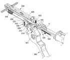
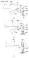
- FIG. 1is a perspective view showing a surgical staple device according to an embodiment of the present invention.
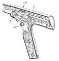
- FIG. 2is a perspective view showing the inside of the handle unit in the surgical staple device according to an embodiment of the present invention.
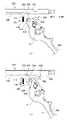
- FIG. 3is a perspective view showing the handle case part removed in FIG. 2 .
- Figure 4is a perspective view showing the drive shaft of the surgical staple device according to an embodiment of the present invention.
- FIG 5is a perspective view showing a first stopper of the surgical staple device according to an embodiment of the present invention.
- FIG. 6is a perspective view showing a portion of the handle case portion of the surgical staple device according to an embodiment of the present invention.
- FIG. 7is a perspective view illustrating a portion “A” of FIG. 6 .
- FIG 8is an exemplary view showing a coupling state of the first stopper portion and the handle case portion of the surgical staple device according to an embodiment of the present invention.
- FIG 9is an exemplary view for explaining the operation of the first stopper unit in the surgical staple device according to an embodiment of the present invention.
- FIG. 10is a perspective view showing a second stopper unit of the surgical staple device according to an embodiment of the present invention.
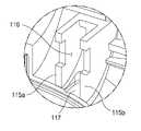
- FIG. 11is a perspective view illustrating a portion “B” of FIG. 6 .
- FIG. 12is an exemplary view for explaining the operation of the second stopper unit in the surgical staple device according to an embodiment of the present invention.
- loading unit 20handle unit
- first installation space 116second installation space
- drive shaft unit 220first ratchet
- first sliding body 411long groove
- first elastic member 500second stopper part
- FIG. 1is a perspective view showing a surgical staple device according to an embodiment of the present invention.
- the surgical staple deviceincludes a loading unit 10 having a cutter (not shown) for excising body tissue and a staple (not shown) for sealing the excision site, and the loading unit 10. It is detachable and may include a handle unit 20 for controlling the operation of the loading unit 10 .
- the loading unit 10is not particularly limited as long as it has a cutter and a staple that implements the functions as described above.
- the handle unit 20will be described in detail.
- FIG. 2is a perspective view showing the inside of the handle unit in the surgical staple device according to an embodiment of the present invention. Specifically, the first case part 110 (refer to FIG. 1 ) is removed and shown. And Figure 3 is a perspective view showing the removal of the handle case portion in Figure 2, Figure 4 is a perspective view showing the drive shaft portion of the surgical staple device according to an embodiment of the present invention.
- the handle unit 20may include a handle case unit 100 , a drive shaft unit 200 , an operation handle unit 300 , and a first stopper unit 400 .
- the handle case part 100may form an outer case of the handle unit 20 .
- the handle case part 100may have a first case part 110 and a second case part 130 , and the first case part 110 and the second case part 130 are the whole except for a part. They may be formed symmetrically with each other.
- the direction from the handle unit 20 to the loading unit 10is the forward direction (FW), and the direction from the loading unit 10 to the handle unit 20 is the rear direction (BW). And, based on this, it will be described as front/front/front/front/front, and rear/rear/rear/rear.
- the drive shaft unit 200may be provided inside the handle case unit 100 to reciprocate in the front-rear direction.
- the drive shaft unit 200may have a shaft body 210 , a first ratchet 220 , and a second ratchet 230 .
- the shaft body 210may form the body of the drive shaft unit 200 and may be formed to extend in the front-rear direction.
- the first ratchet 220may be formed on the lower surface 211 of the shaft body 210 , and a plurality of first ratchets 220 may be formed along the longitudinal direction of the shaft body 210 .
- the first ratchet 220may be formed so that only a force applied to the front is input. That is, when a forward force is applied to the first ratchet 220 , the shaft body 210 may move forward. On the other hand, the force applied to the rear may not be input to the first ratchet 220 , and the shaft body 210 may not move backward.
- the second ratchet 230may be formed on the side surface 212 of the shaft body 210 , and may be formed in a direction opposite to the first ratchet 220 .
- the forward movement of the shaft body 210may be restricted.
- a connecting rod 11 connected to the cutter of the loading unit 10may be coupled to the front end of the drive shaft 200 .
- the connecting rod 11When the drive shaft part 200 moves forward, the connecting rod 11 also moves forward, and accordingly, the cutter may be pushed forward.
- a cutter pushed forwardcan ablate tissue in the body, and staples can be fired to suture the tissue.
- the drive shaft unit 200may have a second inclined surface 240 , an inclined groove 250 , and a locking protrusion 225 .
- the second inclined surface 240may be formed on the lower surface 211 of the front end of the shaft body 210 .
- the inclined groove 250may be formed in the rear of the second inclined surface 240 in the lower surface 211 of the front end of the shaft body 210 .
- the locking jaw 225may be formed in the rear of the inclined groove 250 in the lower surface 211 of the front end of the shaft body 210 .
- the upper portion of the operation handle unit 300may be provided inside the handle case unit 100 , and the remaining portion may extend to the outside of the handle case unit 100 .
- a first hinge hole 301may be formed through the upper portion of the operation handle unit 300 .
- the handle case part 100may have a first hinge shaft 111 (refer to FIG. 6 ), and the first hinge shaft 111 may be coupled to the first hinge hole 301 . Through this, the operation handle unit 300 may be hinge-rotated about the first hinge shaft 111 .
- a handle spring 340may be provided inside the handle case unit 100 .
- the rear end of the handle spring 340may be fixed to the handle case unit 100 , and the front end of the handle spring 340 may be connected to the upper end of the operation handle unit 300 .
- the handle spring 340may generate a contractile restoring force. Accordingly, the handle spring 340 pulls the upper end of the actuating handle unit 300 to the rear, and when the upper end of the rotating actuating handle unit 300 is in close contact with the first stopper unit 400 , the rotation may be stopped.
- FIG. 3a state in which the upper end of the operation handle unit 300 is in close contact with the first stopper unit 400 and the rotation is stopped is referred to as an “initial state”.
- the first stopper part 400may be provided below the drive shaft part 200 at the rear of the upper end of the operation handle part 300 . Specifically, when the drive shaft part 200 is positioned at the rearmost side of the handle case part 100 (hereinafter referred to as a "basic state"), the first stopper part 400 is the drive shaft part 200 . It may be provided under the second ratchet 230 .
- Figure 5is a perspective view showing a first stopper portion of the surgical staple device according to an embodiment of the present invention
- Figure 6is a perspective view showing a portion of the handle case portion of the surgical staple device according to an embodiment of the present invention
- Figure 7is a perspective view showing a portion "A" of FIG. 6
- FIG. 8is an exemplary view showing a coupling state of the first stopper part and the handle case part of the surgical staple device according to an embodiment of the present invention.
- the first stopper part 400may have a first sliding body 410 , a first stop protrusion 420 , and an inclined protrusion 430 .
- the first sliding body 410may form a body of the first stopper part 400 .
- the first sliding body 410may have a long groove 411 extending in the vertical direction.
- the handle case part 100may have first guide protrusions 113a and 113b formed as a pair, and the first sliding body 410 has a first installation space between the first guide protrusions 113a and 113b ( 114) may be provided.
- the first guide protrusions 113a and 113bmay be formed to extend in the vertical direction, and the first sliding body 410 may be moved up and down in the first installation space 114 .
- the front surface of the first sliding body 410may be in close contact with the first guide protrusion 113a in front, and the first sliding body 410 ) may be in close contact with the rear first guide protrusion 113b. Accordingly, when the first sliding body 410 moves up and down, the first guide protrusions 113a and 113b may guide the first sliding body 410 to move up and down stably.
- the handle case part 100may have a fixing protrusion 112 .
- the fixing protrusion 112may be formed to protrude from the upper side of the first installation space 114 .
- the fixing protrusion 112may be inserted into the long groove 411 .
- the fixing protrusion 112may be located on the upper side from the inside of the long groove 411 .
- the first stop protrusion 420may protrude upwardly from the front end of the first sliding body 410 , and may be formed to correspond to the second ratchet 230 .
- the upper surface 421 of the first stop protrusion 420may be inclined.
- the inclined protrusion 430may be formed to protrude downward from the front end of the first sliding body 410 , and the front surface may be formed as the first inclined surface 431 .
- the first stopper part 400may have a first elastic member 450 .
- the first elastic member 450may have an upper end in close contact with the handle case unit 100 , and a lower end in close contact with the first sliding body 410 to elastically support the first sliding body 410 to descend.
- the first elastic member 450may be provided in the long groove (411).
- the upper end of the first elastic member 450 inserted into the long groove 411may be in close contact with the lower end of the fixing protrusion 112 , and the lower end may be in close contact with the lower end of the long groove 411 .
- the first elastic member 450may generate a stretch restoring force. Therefore, based on the fixing protrusion 112, the first elastic member 450 pushes the lower end of the long groove 411 downward, and as a result, the first elastic member 450 is the first sliding body ( 410) can be elastically supported to the lower side.
- the operation handle unit 300may have a pressing protrusion 310 .
- the pressing protrusion 310may protrude from the upper end of the operation handle unit 300 , and when the operation handle unit 300 is pulled and rotated by the handle spring 340 , the pressing projection 310 is formed on the first inclined surface 431 ). can be pressurized.
- FIG 9is an exemplary view for explaining the operation of the first stopper unit in the surgical staple device according to an embodiment of the present invention.
- the surgical staple devicemay include a clasp 600 .
- the clasp 600is coupled to the upper end of the operation handle unit 300 by a second hinge shaft 610 to be hingedly rotated about the second hinge shaft 610 .
- a torsion spring(not shown) may be provided on the second hinge shaft 610 to provide an elastic force for the front end of the clasp 600 to rotate upward.
- a pusher 620may be formed at the front end of the clasp 600 .
- the rear end of the clasp 600may be pressed by the first guide protrusion 113a (see FIG. 7), and thus the clasp Rotation of the part 600 is restricted so that the pusher 620 may be spaced apart from the lower surface of the drive shaft part 200 .
- the restraint by the first guide protrusion 113acan also be released.
- the front end of the latch unit 600may be rotated upward by the elastic restoring force of the torsion spring, and the pusher 620 may be in close contact with the lower surface 211 of the drive shaft unit 200 .
- the pusher 620moves forward and is caught by the locking jaw 225 of the drive shaft part 200, and moves the drive shaft part 200 forward. can be pushed to
- the operation handle unit 300may be rotated back to its initial state by the elastic restoring force of the handle spring 340 (refer to FIG. 3 ).
- the drive shaft part 200since the drive shaft part 200 has already moved forward by a predetermined distance, even if the first stopper part 400 is raised, the first stopper part 400 is not coupled to the second ratchet 230 . do.
- the pusher 620may be coupled to the first ratchet 220, and the pusher 620 pushes the first ratchet 220 forward. Accordingly, the drive shaft 200 may be moved forward.
- the surgical staple devicemay include a second stopper unit 500 .
- the second stopper part 500may be provided on the lower side of the front end of the drive shaft part 200 to be able to move up and down.
- Figure 10is a perspective view showing a second stopper portion of the surgical staple device according to an embodiment of the present invention
- Figure 11is a perspective view showing a portion "B" of Figure 6
- Figure 12is a perspective view according to an embodiment of the present invention It is an exemplary view for explaining the operation of the second stopper unit in the surgical staple device.
- the second stopper part 500may have a second sliding body 510 , a second stop protrusion 520 , and a second elastic member 550 . .
- the second sliding body 510may form a body of the second stopper part 500 .
- the handle case unit 100may have second guide protrusions 115a and 115b formed as a pair, and the second sliding body 510 has a second installation space between the second guide protrusions 115a and 115b ( 116) may be provided.
- the second guide protrusions 115a and 115bmay be formed to extend in the vertical direction, and the second sliding body 510 may be moved up and down in the second installation space 116 .
- the front surface 511 of the second sliding body 510may be in close contact with the second guide protrusion 115a in front, and the second sliding The rear surface 512 of the body 510 may be in close contact with the rear second guide protrusion 115b. Accordingly, when the second sliding body 510 moves up and down, the second guide protrusions 115a and 115b may guide the stable lift motion of the second sliding body 510 .
- the second stop protrusion 520may be formed to protrude from the upper portion of the second sliding body 510 .
- a third inclined surface 521may be formed on the upper surface of the second stop protrusion 520 .
- the second stop protrusion 520may be in close contact with the lower surface of the drive shaft unit 200 .
- the third inclined surface 521 of the second stop protrusion 520may be in close contact with the second inclined surface 240 of the drive shaft unit 200 .
- the second elastic member 550may be provided in the second installation space 116 .
- the upper end of the second elastic member 550may be in close contact with the lower end of the second sliding body 510 , and the lower end may be in close contact with the handle case unit 100 .
- a recess 117 for stably fixing the lower end of the second elastic member 550may be formed in the handle case part 100 .
- the second elastic member 550may elastically support the second stopper part 500 upward.
- the third inclined surface 521 of the second stop protrusion 520may be in close contact with the second inclined surface 240 of the drive shaft part 200 ( FIG. 12 ). of (a)).
- the third inclined surface 521is the second inclined surface ( While sliding at 240 , the second stopper part 500 may naturally descend (see FIG. 12 ( b ) ).
- the second elastic member 550is elastically restored and the second stopper part 500 rises again, and the second stop protrusion 520 is the driving shaft part.
- the drive shaft part 200may be coupled to the inclined groove 250 of the 200 (refer to (c) of FIG. 12).
- the second ratchet 230is also moved forward and the first stopper part It cannot be located on the upper side of 400 . Therefore, even when the operation handle part 300 is returned to the initial state, the first stopper part 400 cannot be coupled to the second ratchet 230, but the drive shaft part ( 200) may be constrained so as not to move backward. This can provide the effect that the drive shaft portion is prevented from being moved backwards unintentionally.
Landscapes
- Health & Medical Sciences (AREA)
- Life Sciences & Earth Sciences (AREA)
- Surgery (AREA)
- Molecular Biology (AREA)
- General Health & Medical Sciences (AREA)
- Biomedical Technology (AREA)
- Heart & Thoracic Surgery (AREA)
- Medical Informatics (AREA)
- Nuclear Medicine, Radiotherapy & Molecular Imaging (AREA)
- Animal Behavior & Ethology (AREA)
- Engineering & Computer Science (AREA)
- Public Health (AREA)
- Veterinary Medicine (AREA)
- Oral & Maxillofacial Surgery (AREA)
- Pathology (AREA)
- Ophthalmology & Optometry (AREA)
- Surgical Instruments (AREA)
Abstract
Description
Translated fromKorean본 발명은 외과용 스테이플 장치에 관한 것으로, 더욱 상세하게는 구성이 간단한 외과용 스테이플 장치에 관한 것이다.The present invention relates to a surgical staple device, and more particularly, to a surgical staple device having a simple configuration.
외과용 스테이플 장치는 조직을 클램핑(clamp) 또는 절단(cut)하기 위하여 그리고 클램핑 또는 절단된 조직을 스테이플(staple)하기 위하여 사용된다. 이와 같이, 외과용 스테이플 장치는 조직을 클램핑 또는 절단하기 위한 메커니즘과, 조직을 관통해 스테이플 드라이브(drive)하기 위한 메커니즘들을 갖는다.A surgical staple device is used to clamp or cut tissue and to staple the clamped or cut tissue. As such, the surgical staple device has a mechanism for clamping or cutting tissue and a mechanism for driving a staple through the tissue.
그리고, 외과용 스테이플 장치는 클램핑 또는 절단된 조직의 적절한 스테이플링을 제공하기 위한 복잡한 메커니즘들과 함께 복수의 트리거(trigger)들 및 핸들(handle)의 구성을 가진다.In addition, the surgical stapling device has a configuration of a plurality of triggers and handles together with complex mechanisms for providing clamping or proper stapling of the cut tissue.
그런데, 이러한 복잡한 메커니즘은 장치의 고장이나, 사용자가 혼란을 느낄 수 있도록 하는 잠재적인 원인이 될 수 있다. 또한, 이러한 복잡한 메커니즘은 부품의 수를 증가시켜 구성이 복잡해지게 되며, 제조 공정도 복잡해지는 원인이 될 수 있다. 따라서, 복잡한 메커니즘을 가지지 않는 구성이 간단한 외과용 스테이플 장치가 요구된다.However, such a complex mechanism may be a potential cause of device failure or user confusion. In addition, such a complicated mechanism increases the number of parts, which makes the configuration complicated, and may also cause the manufacturing process to be complicated. Therefore, there is a need for a surgical staple device having a simple configuration and not having a complicated mechanism.
상기와 같은 문제점을 해결하기 위하여, 본 발명이 이루고자 하는 기술적 과제는 구성이 간단한 외과용 스테이플 장치를 제공하는 것이다.In order to solve the above problems, the technical problem to be achieved by the present invention is to provide a surgical staple device having a simple configuration.
본 발명이 이루고자 하는 기술적 과제는 이상에서 언급한 기술적 과제로 제한되지 않으며, 언급되지 않은 또 다른 기술적 과제들은 아래의 기재로부터 본 발명이 속하는 기술 분야에서 통상의 지식을 가진 자에게 명확하게 이해될 수 있을 것이다.The technical problems to be achieved by the present invention are not limited to the technical problems mentioned above, and other technical problems not mentioned can be clearly understood by those of ordinary skill in the art to which the present invention belongs from the description below. There will be.
상기 기술적 과제를 달성하기 위하여, 본 발명의 일실시예는 신체의 조직을 절제하는 커터 및 절제 부위를 봉합하기 위한 스테이플을 가지는 로딩유닛과, 상기 로딩유닛이 탈착되고 상기 로딩유닛의 작동을 제어하기 위한 핸들유닛을 포함하는 외과용 스테이플 장치로서, 상기 핸들유닛은 핸들 케이스부; 상기 핸들 케이스부의 내측에 전후방향으로 왕복 이동 가능하게 구비되는 구동 샤프트부; 상기 핸들 케이스부에 힌지 회전되도록 구비되는 작동 핸들부; 상기 구동 샤프트부의 일측에 구비되되, 상기 작동 핸들부의 동작에 의하여 상하방향으로 이동되면서 상기 구동 샤프트부의 전방 이동을 선택적으로 구속하는 제1스토퍼부; 그리고 상기 구동 샤프트부의 전단부의 하측에 승강 가능하게 구비되고, 상승되면 상기 구동 샤프트부의 하면에 밀착되는 제2스토퍼부를 포함하는 것을 특징으로 하는 외과용 스테이플 장치를 제공한다.In order to achieve the above technical object, an embodiment of the present invention includes a loading unit having a cutter for excising body tissue and a staple for sealing the ablation site, and the loading unit is detached and to control the operation of the loading unit A surgical staple device comprising a handle unit for: a handle case unit; a drive shaft portion provided to be reciprocally movable in the front and rear directions inside the handle case portion; an operation handle portion provided to be hingedly rotated on the handle case portion; a first stopper part provided on one side of the drive shaft part and selectively restricting forward movement of the drive shaft part while moving in the vertical direction by the operation of the operation handle part; And it provides a surgical staple device, characterized in that it is provided on the lower side of the front end of the drive shaft to be elevating, and comprising a second stopper that is in close contact with the lower surface of the drive shaft when raised.
본 발명의 실시예에 있어서, 상기 구동 샤프트부는 전방으로 가해지는 힘이 입력되도록 하면에 형성되는 제1래칫과, 측면에 상기 제1래칫과 반대 방향으로 형성되는 제2래칫을 가지며, 초기 상태에서 상기 작동 핸들부는 상기 제1스토퍼부를 밀어 올려 상기 제1스토퍼부가 상기 제2래칫에 결합된 상태가 되도록 하고, 상기 작동 핸들부가 당겨지는 방향으로 회전되면, 상기 제1스토퍼부는 하강되어 상기 제2래칫과의 결합이 해제될 수 있다.In an embodiment of the present invention, the drive shaft portion has a first ratchet formed on a lower surface to receive a force applied to the front, and a second ratchet formed on a side surface in the opposite direction to the first ratchet, and in the initial state The operation handle portion pushes up the first stopper portion so that the first stopper portion is coupled to the second ratchet, and when the operation handle portion is rotated in the pulling direction, the first stopper portion is lowered to the second ratchet may be disassociated from it.
본 발명의 실시예에 있어서, 상기 제1스토퍼부는 승강되도록 구비되는 제1슬라이딩 몸체와, 상단부는 상기 핸들 케이스부에 밀착되고, 하단부는 상기 제1슬라이딩 몸체에 밀착되어 상기 제1슬라이딩 몸체가 하강되도록 탄발 지지하는 제1탄성부재를 가질 수 있다.In an embodiment of the present invention, the first stopper portion includes a first sliding body provided to be raised and lowered, an upper end is in close contact with the handle case portion, and a lower end is in close contact with the first sliding body to lower the first sliding body. It may have a first elastic member that elastically supports as much as possible.
본 발명의 실시예에 있어서, 상기 제1슬라이딩 몸체는 상하방향으로 연장 형성되는 장홈을 가지고, 상기 제1탄성부재는 상기 장홈에 구비되어 상단부는 상기 핸들 케이스부에 밀착되고, 하단부는 상기 장홈의 하단부에 밀착되어 상기 제1슬라이딩 몸체를 하측으로 탄발 지지할 수 있다.In the embodiment of the present invention, the first sliding body has a long groove extending in the vertical direction, the first elastic member is provided in the long groove, the upper end is in close contact with the handle case portion, the lower end of the long groove It is closely attached to the lower end and can elastically support the first sliding body downward.
본 발명의 실시예에 있어서, 상기 핸들 케이스부는 상기 장홈의 내측 상부로 연장 형성되는 고정돌기를 가지며, 상기 제1탄성부재의 상단부는 상기 고정돌기의 하단부에 밀착될 수 있다.In an embodiment of the present invention, the handle case portion may have a fixing protrusion extending to the inner upper portion of the long groove, and the upper end of the first elastic member may be in close contact with the lower end of the fixing protrusion.
본 발명의 실시예에 있어서, 상기 제1스토퍼부는 상기 제1슬라이딩 몸체의 전단부에 상기 제2래칫에 대응되도록 상측으로 돌출 형성되어 상기 제1슬라이딩 몸체가 상승 시에 상기 제2래칫에 결합되는 제1스톱돌기를 가질 수 있다.In an embodiment of the present invention, the first stopper part is formed to protrude upward to correspond to the second ratchet at the front end of the first sliding body, and is coupled to the second ratchet when the first sliding body is raised. It may have a first stop projection.
본 발명의 실시예에 있어서, 상기 핸들 케이스부는 상기 제1슬라이딩 몸체의 앞면 및 후면에 밀착되어 상기 제1슬라이딩 몸체의 승강을 안내하는 제1안내돌기를 가질 수 있다.In an embodiment of the present invention, the handle case portion may have a first guide protrusion in close contact with the front and rear surfaces of the first sliding body to guide the elevation of the first sliding body.
본 발명의 실시예에 있어서, 상기 제1스토퍼부는 상기 제1슬라이딩 몸체의 전단부 하측으로 돌출 형성되고, 전(Front)면이 제1경사면으로 형성되는 경사돌기를 가질 수 있다.In an embodiment of the present invention, the first stopper part may have an inclined protrusion that is formed to protrude below the front end of the first sliding body, and a front surface is formed as a first inclined surface.
본 발명의 실시예에 있어서, 상기 작동 핸들부는 상기 작동 핸들부가 당겨진 상태에서 초기 상태로 회전되면 상기 제1경사면을 가압하여 상기 제1슬라이딩 몸체가 상승 이동되도록, 상기 작동 핸들부의 상단부에 돌출 형성되는 누름돌기를 가질 수 있다.In an embodiment of the present invention, the operation handle portion is formed to protrude from the upper end of the operation handle portion so that the first sliding body is moved upward by pressing the first inclined surface when the operation handle portion is rotated to the initial state in the pulled state It may have a pressing protrusion.
본 발명의 실시예에 있어서, 상기 작동 핸들부의 상단부에 힌지 회전되도록 구비되고, 상기 작동 핸들부가 당겨지는 방향으로 회전되면, 상기 제1래칫에 걸려 상기 구동 샤프트부를 전방으로 밀어내는 걸쇠부를 포함할 수 있다.In an embodiment of the present invention, it is provided to be hinged on the upper end of the operation handle portion, and when the operation handle portion is rotated in a pulling direction, it may include a clasp portion that is caught by the first ratchet and pushes the drive shaft portion forward. have.
본 발명의 실시예에 있어서, 상기 제2스토퍼부는 승강되도록 구비되는 제2슬라이딩 몸체와, 하단부는 상기 핸들 케이스부에 밀착되고, 상단부는 상기 제2슬라이딩 몸체의 하단부에 밀착되어 상기 제2슬라이딩 몸체를 상측으로 탄발 지지하는 제2탄성부재를 포함할 수 있다.In an embodiment of the present invention, the second stopper portion includes a second sliding body provided to be lifted, a lower end in close contact with the handle case, and an upper end in close contact with the lower end of the second sliding body, the second sliding body It may include a second elastic member for elastically supporting the upper side.
본 발명의 실시예에 있어서, 상기 구동 샤프트부는 전단부 하면에 형성되는 제2경사면과, 상기 구동 샤프트부의 전단부 하면에서 상기 제2경사면의 후방에 형성되는 경사홈을 가지고, 상기 제2스토퍼부는 상기 제2슬라이딩 몸체의 상부에 돌출 형성되고 제3경사면을 가지는 제2스톱돌기를 가지며, 상기 제3경사면이 상기 제2경사면에 밀착된 상태에서 상기 구동 샤프트부가 전방으로 이동되면, 상기 제2스토퍼부는 하강한 후 다시 상승하면서 상기 경사홈에 결합되어 상기 구동 샤프트부의 후방 이동을 구속할 수 있다.In an embodiment of the present invention, the drive shaft portion has a second inclined surface formed on a lower surface of the front end portion, and an inclined groove formed behind the second inclined surface on the lower surface of the front end portion of the drive shaft portion, and the second stopper portion The second stopper is formed to protrude from the upper portion of the second sliding body and has a second stop protrusion having a third inclined surface, and when the drive shaft part is moved forward while the third inclined surface is in close contact with the second inclined surface, the second stopper The part may be coupled to the inclined groove while ascending again after descending to restrict the rear movement of the drive shaft part.
본 발명의 실시예에 있어서, 상기 핸들 케이스부는 상기 제2슬라이딩 몸체의 앞면 및 후면에 밀착되어 상기 제2슬라이딩 몸체의 승강을 안내하는 제2안내돌기를 가질 수 있다.In an embodiment of the present invention, the handle case part may have a second guide protrusion in close contact with the front and rear surfaces of the second sliding body to guide the elevation of the second sliding body.
본 발명의 실시예에 따르면, 구동 샤프트부가 제2래칫을 가지고, 제2래칫과 결합되는 제1스토퍼부가 구비되도록 함으로써, 구동 샤프트부가 의도하지 않게 전방으로 이동되는 것이 방지될 수 있다. 그리고, 작동 핸들부가 당겨지고 구동 샤프트부가 전방으로 이동되면 제1스토퍼부 및 제2래칫은 자연스럽게 결합이 해제될 수 있다.According to the embodiment of the present invention, by providing the drive shaft portion with the second ratchet and the first stopper portion coupled to the second ratchet, it is possible to prevent the drive shaft portion from being moved forward unintentionally. Then, when the operation handle part is pulled and the drive shaft part is moved forward, the first stopper part and the second ratchet may be naturally released from coupling.
또한, 본 발명의 실시예에 따르면, 구동 샤프트부가 전방으로 이동 시에 제2스토퍼부는 구동 샤프트부에 의해 자연스럽게 하강되도록 구성된다. 따라서, 작동 핸들부 및 제2스토퍼부를 연결하는 별도의 링크 구조가 생략될 수 있어 구성이 간단해질 수 있다.Further, according to the embodiment of the present invention, the second stopper portion is configured to naturally lower by the drive shaft portion when the drive shaft portion moves forward. Accordingly, a separate link structure connecting the operation handle unit and the second stopper unit may be omitted, and thus the configuration may be simplified.
본 발명의 효과는 상기한 효과로 한정되는 것은 아니며, 본 발명의 상세한 설명 또는 청구범위에 기재된 발명의 구성으로부터 추론 가능한 모든 효과를 포함하는 것으로 이해되어야 한다.It should be understood that the effects of the present invention are not limited to the above-described effects, and include all effects that can be inferred from the configuration of the invention described in the detailed description or claims of the present invention.
도 1은 본 발명의 일실시예에 따른 외과용 스테이플 장치를 나타낸 사시도이다.1 is a perspective view showing a surgical staple device according to an embodiment of the present invention.
도 2는 본 발명의 일실시예에 따른 외과용 스테이플 장치에서 핸들유닛의 내부를 중심으로 나타낸 사시도이다.2 is a perspective view showing the inside of the handle unit in the surgical staple device according to an embodiment of the present invention.
도 3은 도 2에서 핸들 케이스부를 제거하고 나타낸 사시도이다.FIG. 3 is a perspective view showing the handle case part removed in FIG. 2 .
도 4는 본 발명의 일실시예에 따른 외과용 스테이플 장치의 구동 샤프트부를 나타낸 사시도이다.Figure 4 is a perspective view showing the drive shaft of the surgical staple device according to an embodiment of the present invention.
도 5는 본 발명의 일실시예에 따른 외과용 스테이플 장치의 제1스토퍼부를 나타낸 사시도이다.5 is a perspective view showing a first stopper of the surgical staple device according to an embodiment of the present invention.
도 6은 본 발명의 일실시예에 따른 외과용 스테이플 장치의 핸들 케이스부의 일부를 나타낸 사시도이다.6 is a perspective view showing a portion of the handle case portion of the surgical staple device according to an embodiment of the present invention.
도 7은 도 6의 "A" 부분을 나타낸 사시도이다.7 is a perspective view illustrating a portion “A” of FIG. 6 .
도 8은 본 발명의 일실시예에 따른 외과용 스테이플 장치의 제1스토퍼부와 핸들 케이스부의 결합상태를 나타낸 예시도이다.8 is an exemplary view showing a coupling state of the first stopper portion and the handle case portion of the surgical staple device according to an embodiment of the present invention.
도 9는 본 발명의 일실시예에 따른 외과용 스테이플 장치에서 제1스토퍼부의 작동을 설명하기 위한 예시도이다.9 is an exemplary view for explaining the operation of the first stopper unit in the surgical staple device according to an embodiment of the present invention.
도 10은 본 발명의 일실시예에 따른 외과용 스테이플 장치의 제2스토퍼부를 나타낸 사시도이다.10 is a perspective view showing a second stopper unit of the surgical staple device according to an embodiment of the present invention.
도 11은 도 6의 "B" 부분을 나타낸 사시도이다.11 is a perspective view illustrating a portion “B” of FIG. 6 .
도 12는 본 발명의 일실시예에 따른 외과용 스테이플 장치에서 제2스토퍼부의 작동을 설명하기 위한 예시도이다.12 is an exemplary view for explaining the operation of the second stopper unit in the surgical staple device according to an embodiment of the present invention.
<도면의 주요 부분에 대한 부호의 설명><Explanation of symbols for main parts of the drawing>
10: 로딩유닛20: 핸들유닛10: loading unit 20: handle unit
100: 핸들 케이스부112: 고정돌기100: handle case portion 112: fixing projection
114: 제1설치공간116: 제2설치공간114: first installation space 116: second installation space
200: 구동 샤프트부220: 제1래칫200: drive shaft unit 220: first ratchet
230: 제2래칫300: 작동 핸들부230: second ratchet 300: operation handle portion
310: 누름돌기400: 제1스토퍼부310: pusher 400: first stopper part
410: 제1슬라이딩 몸체411: 장홈410: first sliding body 411: long groove
420: 제1스톱돌기430: 경사돌기420: first stop projection 430: inclined projection
450: 제1탄성부재500: 제2스토퍼부450: first elastic member 500: second stopper part
510: 제2슬라이딩 몸체520: 제2스톱돌기510: second sliding body 520: second stop projection
550: 제2탄성부재600: 걸쇠부550: second elastic member 600: clasp portion
620: 푸셔620: pusher
이하에서는 첨부한 도면을 참조하여 본 발명을 설명하기로 한다. 그러나 본 발명은 여러 가지 상이한 형태로 구현될 수 있으며, 따라서 여기에서 설명하는 실시예로 한정되는 것은 아니다. 그리고 도면에서 본 발명을 명확하게 설명하기 위해서 설명과 관계없는 부분은 생략하였으며, 명세서 전체를 통하여 유사한 부분에 대해서는 유사한 도면 부호를 붙였다.Hereinafter, the present invention will be described with reference to the accompanying drawings. However, the present invention may be embodied in several different forms, and thus is not limited to the embodiments described herein. And in order to clearly explain the present invention in the drawings, parts irrelevant to the description are omitted, and similar reference numerals are attached to similar parts throughout the specification.
명세서 전체에서, 어떤 부분이 다른 부분과 "연결(접속, 접촉, 결합)"되어 있다고 할 때, 이는 "직접적으로 연결"되어 있는 경우뿐 아니라, 그 중간에 다른 부재를 사이에 두고 "간접적으로 연결"되어 있는 경우도 포함한다. 또한 어떤 부분이 어떤 구성요소를 "포함"한다고 할 때, 이는 특별히 반대되는 기재가 없는 한 다른 구성요소를 제외하는 것이 아니라 다른 구성요소를 더 구비할 수 있다는 것을 의미한다.Throughout the specification, when a part is said to be “connected (connected, contacted, coupled)” with another part, it is not only “directly connected” but also “indirectly connected” with another member interposed therebetween. "Including cases where In addition, when a part "includes" a certain component, this means that other components may be further provided without excluding other components unless otherwise stated.
본 명세서에서 사용한 용어는 단지 특정한 실시예를 설명하기 위해 사용된 것으로, 본 발명을 한정하려는 의도가 아니다. 단수의 표현은 문맥상 명백하게 다르게 뜻하지 않는 한, 복수의 표현을 포함한다. 본 명세서에서, "포함하다" 또는 "가지다" 등의 용어는 명세서상에 기재된 특징, 숫자, 단계, 동작, 구성요소, 부품 또는 이들을 조합한 것이 존재함을 지정하려는 것이지, 하나 또는 그 이상의 다른 특징들이나 숫자, 단계, 동작, 구성요소, 부품 또는 이들을 조합한 것들의 존재 또는 부가 가능성을 미리 배제하지 않는 것으로 이해되어야 한다.The terminology used herein is used only to describe specific embodiments, and is not intended to limit the present invention. The singular expression includes the plural expression unless the context clearly dictates otherwise. In the present specification, terms such as “comprise” or “have” are intended to designate that a feature, number, step, operation, component, part, or combination thereof described in the specification exists, but one or more other features It should be understood that this does not preclude the existence or addition of numbers, steps, operations, components, parts, or combinations thereof.
이하 첨부된 도면을 참고하여 본 발명의 실시예를 상세히 설명하기로 한다.Hereinafter, embodiments of the present invention will be described in detail with reference to the accompanying drawings.
도 1은 본 발명의 일실시예에 따른 외과용 스테이플 장치를 나타낸 사시도이다.1 is a perspective view showing a surgical staple device according to an embodiment of the present invention.
도 1에서 보는 바와 같이, 외과용 스테이플 장치는 신체의 조직을 절제하는 커터(미도시) 및 절제 부위를 봉합하기 위한 스테이플(미도시)을 가지는 로딩유닛(10)과, 로딩유닛(10)이 탈착되고 로딩유닛(10)의 작동을 제어하기 위한 핸들유닛(20)을 포함할 수 있다. 로딩유닛(10)은 전술한 바와 같은 기능을 구현하는 커터 및 스테이플을 가진다면 특정하게 한정되는 것은 아니다. 이하에서는 핸들유닛(20)에 대해 상세히 설명한다.As shown in FIG. 1, the surgical staple device includes a
도 2는 본 발명의 일실시예에 따른 외과용 스테이플 장치에서 핸들유닛의 내부를 중심으로 나타낸 사시도인데, 구체적으로는 제1케이스부(110, 도 1 참조)를 제거하고 나타낸 것이다. 그리고 도 3은 도 2에서 핸들 케이스부를 제거하고 나타낸 사시도이며, 도 4는 본 발명의 일실시예에 따른 외과용 스테이플 장치의 구동 샤프트부를 나타낸 사시도이다.FIG. 2 is a perspective view showing the inside of the handle unit in the surgical staple device according to an embodiment of the present invention. Specifically, the first case part 110 (refer to FIG. 1 ) is removed and shown. And Figure 3 is a perspective view showing the removal of the handle case portion in Figure 2, Figure 4 is a perspective view showing the drive shaft portion of the surgical staple device according to an embodiment of the present invention.
도 1 내지 도 4에서 보는 바와 같이, 핸들유닛(20)은 핸들 케이스부(100), 구동 샤프트부(200), 작동 핸들부(300) 그리고 제1스토퍼부(400)를 포함할 수 있다.1 to 4 , the
핸들 케이스부(100)는 핸들유닛(20)의 외부 케이스를 형성할 수 있다. 핸들 케이스부(100)는 제1케이스부(110) 및 제2케이스부(130)를 가질 수 있으며, 제1케이스부(110) 및 제2케이스부(130)는 일부분을 제외하고는 전체적으로는 서로 대칭으로 형성될 수 있다.The
이하에서는 설명의 편의상, 핸들유닛(20)에서 로딩유닛(10)으로의 방향을 전방 방향(FW)으로 하고, 로딩유닛(10)에서 핸들유닛(20)으로의 방향을 후방 방향(BW)으로 하며, 이를 기준으로, 전단/전단부/전방/전(Front)면/앞면, 후단/후단부/후방/후면으로 하여 설명한다.Hereinafter, for convenience of explanation, the direction from the
구동 샤프트부(200)는 핸들 케이스부(100)의 내측에 전후방향으로 왕복 이동되도록 구비될 수 있다. 구동 샤프트부(200)는 샤프트 몸체(210), 제1래칫(220) 및 제2래칫(230)을 가질 수 있다.The
샤프트 몸체(210)는 구동 샤프트부(200)의 몸체를 형성할 수 있으며, 전후방향으로 연장된 형태로 형성될 수 있다.The
제1래칫(220)은 샤프트 몸체(210)의 하면(211)에 형성될 수 있으며, 샤프트 몸체(210)의 길이방향을 따라 복수개가 형성될 수 있다. 제1래칫(220)은 전방으로 가해지는 힘만 입력되도록 형성될 수 있다. 즉, 전방으로 가해지는 힘이 제1래칫(220)에 가해지면 샤프트 몸체(210)는 전방으로 이동될 수 있다. 반면 후방으로 가해지는 힘은 제1래칫(220)에는 입력되지 못하고, 샤프트 몸체(210)는 후방으로 이동되지 않을 수 있다.The
한편, 제2래칫(230)은 샤프트 몸체(210)의 측면(212)에 형성될 수 있으며, 제1래칫(220)과 반대 방향으로 형성될 수 있다. 제2래칫(230)이 고정된 구조물과 결합되면, 샤프트 몸체(210)는 전방으로의 이동이 구속될 수 있다.Meanwhile, the
구동 샤프트부(200)의 전단부에는 로딩유닛(10)의 커터와 연결되는 연결로드(11)가 결합될 수 있다. 구동 샤프트부(200)가 전방으로 이동하게 되면, 연결로드(11)도 전방으로 이동되고, 이에 따라, 커터는 전방으로 밀려날 수 있다. 전방으로 밀려나는 커터는 신체의 조직을 절제할 수 있으며, 스테이플이 발사되어 조직이 봉합될 수 있다.A connecting
그리고, 구동 샤프트부(200)는 제2경사면(240), 경사홈(250) 및 걸림턱(225)을 가질 수 있다.In addition, the
제2경사면(240)은 샤프트 몸체(210)의 전단부 하면(211)에 형성될 수 있다. 경사홈(250)은 샤프트 몸체(210)의 전단부 하면(211)에서 제2경사면(240)의 후방에 형성될 수 있다. 그리고, 걸림턱(225)은 샤프트 몸체(210)의 전단부 하면(211)에서 경사홈(250)의 후방에 형성될 수 있다.The second
작동 핸들부(300)는 상부는 핸들 케이스부(100)의 내측에 구비될 수 있고, 나머지 부분은 핸들 케이스부(100)의 외측으로 연장될 수 있다. 작동 핸들부(300)의 상부에는 제1힌지공(301)이 관통 형성될 수 있다. 그리고, 핸들 케이스부(100)는 제1힌지축(111, 도 6 참조)을 가질 수 있으며, 제1힌지축(111)은 제1힌지공(301)에 결합될 수 있다. 이를 통해, 작동 핸들부(300)는 제1힌지축(111)을 중심으로 힌지 회전될 수 있다.The upper portion of the
핸들 케이스부(100)의 내측에는 핸들 스프링(340)이 구비될 수 있다. 핸들 스프링(340)의 후단부는 핸들 케이스부(100)에 고정될 수 있으며, 핸들 스프링(340)의 전단부는 작동 핸들부(300)의 상단부에 연결될 수 있다. 핸들 스프링(340)은 수축 복원력을 발생할 수 있다. 따라서 핸들 스프링(340)은 작동 핸들부(300)의 상단부를 후방으로 당기게 되고, 회전되는 작동 핸들부(300)의 상단부가 제1스토퍼부(400)에 밀착되면 회전이 멈출 수 있다. 이하에서는 도 3에서와 같이, 작동 핸들부(300)의 상단부가 제1스토퍼부(400)에 밀착되면서 회전이 멈춘 상태를 "초기 상태"라 한다.A
제1스토퍼부(400)는 작동 핸들부(300)의 상단부 후방에서 구동 샤프트부(200)의 하측에 구비될 수 있다. 구체적으로, 구동 샤프트부(200)가 핸들 케이스부(100)의 제일 후방에 위치된 상태(이하 "기본 상태"라 함)일 때, 제1스토퍼부(400)는 구동 샤프트부(200)의 제2래칫(230)의 하측에 구비될 수 있다.The
도 5는 본 발명의 일실시예에 따른 외과용 스테이플 장치의 제1스토퍼부를 나타낸 사시도이고, 도 6은 본 발명의 일실시예에 따른 외과용 스테이플 장치의 핸들 케이스부의 일부를 나타낸 사시도이고, 도 7은 도 6의 "A" 부분을 나타낸 사시도이고, 도 8은 본 발명의 일실시예에 따른 외과용 스테이플 장치의 제1스토퍼부와 핸들 케이스부의 결합상태를 나타낸 예시도이다.Figure 5 is a perspective view showing a first stopper portion of the surgical staple device according to an embodiment of the present invention, Figure 6 is a perspective view showing a portion of the handle case portion of the surgical staple device according to an embodiment of the present invention, Figure 7 is a perspective view showing a portion "A" of FIG. 6, and FIG. 8 is an exemplary view showing a coupling state of the first stopper part and the handle case part of the surgical staple device according to an embodiment of the present invention.
도 5 내지 도 8에서 보는 바와 같이, 제1스토퍼부(400)는 제1슬라이딩 몸체(410), 제1스톱돌기(420) 그리고 경사돌기(430)를 가질 수 있다.5 to 8 , the
제1슬라이딩 몸체(410)는 제1스토퍼부(400)의 몸체를 형성할 수 있다. 제1슬라이딩 몸체(410)는 상하방향으로 연장 형성되는 장홈(411)을 가질 수 있다.The first sliding
핸들 케이스부(100)는 한 쌍으로 형성되는 제1안내돌기(113a,113b)를 가질 수 있으며, 제1슬라이딩 몸체(410)는 제1안내돌기(113a,113b) 사이의 제1설치공간(114)에 구비될 수 있다. 제1안내돌기(113a,113b)는 상하방향으로 연장 형성될 수 있으며, 제1슬라이딩 몸체(410)는 제1설치공간(114)에서 승강 이동될 수 있다. 제1슬라이딩 몸체(410)가 제1설치공간(114)에 구비되면, 제1슬라이딩 몸체(410)의 앞면은 전방의 제1안내돌기(113a)에 밀착될 수 있고, 제1슬라이딩 몸체(410)의 후면은 후방의 제1안내돌기(113b)에 밀착될 수 있다. 따라서, 제1슬라이딩 몸체(410)가 승강 이동 시에, 제1안내돌기(113a,113b)는 제1슬라이딩 몸체(410)가 안정적으로 승강 이동되도록 안내할 수 있다.The
그리고, 핸들 케이스부(100)는 고정돌기(112)를 가질 수 있다. 고정돌기(112)는 제1설치공간(114)의 상측에 돌출되어 연장 형성될 수 있다. 제1설치공간(114)에 제1슬라이딩 몸체(410)가 위치되었을 때, 고정돌기(112)는 장홈(411)에 삽입될 수 있다. 고정돌기(112)는 장홈(411) 내측에서 상측에 위치될 수 있다.In addition, the
제1스톱돌기(420)는 제1슬라이딩 몸체(410)의 전단부에 상측으로 돌출 형성될 수 있으며, 제2래칫(230)에 대응되도록 형성될 수 있다. 제1스톱돌기(420)의 상면(421)은 경사지게 형성될 수 있다.The
경사돌기(430)는 제1슬라이딩 몸체(410)의 전단부에 하측으로 돌출 형성될 수 있으며, 앞면이 제1경사면(431)으로 형성될 수 있다.The
제1스토퍼부(400)는 제1탄성부재(450)를 가질 수 있다. 제1탄성부재(450)는 상단부는 핸들 케이스부(100)에 밀착되고, 하단부는 제1슬라이딩 몸체(410)에 밀착되어 제1슬라이딩 몸체(410)가 하강되도록 탄발 지지할 수 있다. 구체적으로, 제1탄성부재(450)는 장홈(411)에 구비될 수 있다. 장홈(411)에 삽입된 제1탄성부재(450)의 상단부는 고정돌기(112)의 하단부에 밀착될 수 있고, 하단부는 장홈(411)의 하단부에 밀착될 수 있다. 제1탄성부재(450)는 신장 복원력을 발생할 수 있다. 따라서, 고정돌기(112)를 기준으로 했을 때, 제1탄성부재(450)는 장홈(411)의 하단부를 하측방향으로 밀어내게 되고, 결과적으로 제1탄성부재(450)는 제1슬라이딩 몸체(410)를 하측으로 탄발 지지할 수 있게 된다.The
다시, 도 2 및 도 3을 참조하면, 작동 핸들부(300)는 누름돌기(310)를 가질 수 있다. 누름돌기(310)는 작동 핸들부(300)의 상단부에 돌출 형성될 수 있으며, 작동 핸들부(300)가 핸들 스프링(340)에 의해 당겨져 회전되면 누름돌기(310)는 제1경사면(431)을 가압할 수 있다.Again, referring to FIGS. 2 and 3 , the
도 9는 본 발명의 일실시예에 따른 외과용 스테이플 장치에서 제1스토퍼부의 작동을 설명하기 위한 예시도이다.9 is an exemplary view for explaining the operation of the first stopper unit in the surgical staple device according to an embodiment of the present invention.
도 9의 (a)에서와 같이, 구동 샤프트부(200)가 기본 상태이고, 작동 핸들부(300)가 초기 상태일 때, 작동 핸들부(300)의 누름돌기(310)는 제1경사면(431)을 가압하게 된다. 그러면, 제1슬라이딩 몸체(410)는 상승 이동되고, 제1탄성부재(450)는 압축될 수 있다. 그리고, 제1스톱돌기(420)는 제2래칫(230)에 결합되고, 이에 따라, 구동 샤프트부(200)는 전방으로 이동되지 않도록 구속될 수 있다. 이는 구동 샤프트부가 의도하지 않게 전방으로 이동되는 것이 방지되도록 하는 효과를 제공할 수 있다.As in (a) of FIG. 9 , when the
한편, 외과용 스테이플 장치는 걸쇠부(600)를 포함할 수 있다. 걸쇠부(600)는 작동 핸들부(300)의 상단부에 제2힌지축(610)에 의해 결합되어 제2힌지축(610)을 중심으로 힌지 회전될 수 있다. 제2힌지축(610)에는 걸쇠부(600)의 전단부가 상향으로 회전되도록 하는 탄성력을 제공하는 토션 스프링(미도시)이 구비될 수 있다. 걸쇠부(600)의 전단에는 푸셔(620)가 형성될 수 있다.On the other hand, the surgical staple device may include a
도 9의 (a)에서와 같이 작동 핸들부(300)가 초기 상태일 때, 걸쇠부(600)의 후단부는 제1안내돌기(113a, 도 7 참조)에 의해 가압될 수 있고, 이에 따라 걸쇠부(600)의 회전이 구속되어 푸셔(620)는 구동 샤프트부(200)의 하면에서 이격된 상태가 될 수 있다.When the
그러다가, 도 9의 (b)에서와 같이 작동 핸들부(300)가 사용자에 의해 당겨지면(A1), 즉, 제1힌지축(111)을 중심으로 작동 핸들부(300)의 상부가 전방으로 회전하게 되면, 누름돌기(310)는 경사돌기(430)를 누르지 못하게 된다. 그러면, 제1탄성부재(450)의 탄성 복원력에 의해 제1스토퍼부(400)는 하측으로 이동되고, 제1스톱돌기(420)는 제2래칫(230)에서 분리되어 결합이 해제될 수 있다.Then, as shown in (b) of FIG. 9 , when the operation handle
동시에, 걸쇠부(600)의 후단부도 제1안내돌기(113a)로부터 떨어지게 되기 때문에, 제1안내돌기(113a)에 의한 구속도 해제될 수 있다. 그러면 토션 스프링의 탄성 복원력에 의해 걸쇠부(600)의 전단부는 상향 회전될 수 있으며, 푸셔(620)는 구동 샤프트부(200)의 하면(211)에 밀착될 수 있다. 그리고, 작동 핸들부(300)의 회전(A1)이 계속되면, 푸셔(620)는 전방으로 이동하면서 구동 샤프트부(200)의 걸림턱(225)에 걸리게 되고, 구동 샤프트부(200)를 전방으로 밀어낼 수 있다.At the same time, since the rear end of the
이후, 사용자가 작동 핸들부(300)를 당기는 힘이 제거되면, 핸들 스프링(340, 도 3 참조)의 탄성 복원력에 의해 작동 핸들부(300)는 다시 초기 상태로 회전될 수 있다. 이때, 구동 샤프트부(200)는 이미 전방으로 일정거리만큼 이동된 상태이기 때문에, 제1스토퍼부(400)가 상승되더라도 제1스토퍼부(400)는 제2래칫(230)과 결합되지는 못하게 된다. 그리고, 사용자에 의해 작동 핸들부(300)가 다시 당겨지게 되면, 푸셔(620)는 제1래칫(220)에 결합될 수 있고, 푸셔(620)가 제1래칫(220)을 전방으로 밀어냄에 따라 구동 샤프트부(200)는 전방으로 이동될 수 있다.Thereafter, when the user's pulling force on the
한편, 외과용 스테이플 장치는 제2스토퍼부(500)를 포함할 수 있다. 제2스토퍼부(500)는 구동 샤프트부(200)의 전단부의 하측에 승강 가능하게 구비될 수 있다.Meanwhile, the surgical staple device may include a
도 10은 본 발명의 일실시예에 따른 외과용 스테이플 장치의 제2스토퍼부를 나타낸 사시도이고, 도 11은 도 6의 "B" 부분을 나타낸 사시도이고, 도 12는 본 발명의 일실시예에 따른 외과용 스테이플 장치에서 제2스토퍼부의 작동을 설명하기 위한 예시도이다.Figure 10 is a perspective view showing a second stopper portion of the surgical staple device according to an embodiment of the present invention, Figure 11 is a perspective view showing a portion "B" of Figure 6, Figure 12 is a perspective view according to an embodiment of the present invention It is an exemplary view for explaining the operation of the second stopper unit in the surgical staple device.
도 3과 함께, 도 10 내지 도 12에서 보는 바와 같이, 제2스토퍼부(500)는 제2슬라이딩 몸체(510), 제2스톱돌기(520) 및 제2탄성부재(550)를 가질 수 있다.Together with FIG. 3 , as shown in FIGS. 10 to 12 , the
제2슬라이딩 몸체(510)는 제2스토퍼부(500)의 몸체를 형성할 수 있다. 핸들 케이스부(100)는 한 쌍으로 형성되는 제2안내돌기(115a,115b)를 가질 수 있으며, 제2슬라이딩 몸체(510)는 제2안내돌기(115a,115b) 사이의 제2설치공간(116)에 구비될 수 있다. 제2안내돌기(115a,115b)는 상하방향으로 연장 형성될 수 있으며, 제2슬라이딩 몸체(510)는 제2설치공간(116)에서 승강 이동될 수 있다. 제2슬라이딩 몸체(510)가 제2설치공간(116)에 구비되면, 제2슬라이딩 몸체(510)의 앞면(511)은 전방의 제2안내돌기(115a)에 밀착될 수 있고, 제2슬라이딩 몸체(510)의 후면(512)은 후방의 제2안내돌기(115b)에 밀착될 수 있다. 따라서, 제2슬라이딩 몸체(510)가 승강 이동 시에, 제2안내돌기(115a,115b)는 제2슬라이딩 몸체(510)의 안정적인 승강 이동을 안내할 수 있다.The second sliding
제2스톱돌기(520)는 제2슬라이딩 몸체(510)의 상부에 돌출 형성될 수 있다. 제2스톱돌기(520)의 상면에는 제3경사면(521)이 형성될 수 있다. 제2슬라이딩 몸체(510)가 상승 이동되면, 제2스톱돌기(520)는 구동 샤프트부(200)의 하면에 밀착될 수 있다. 구체적으로, 제2스톱돌기(520)의 제3경사면(521)은 구동 샤프트부(200)의 제2경사면(240)에 밀착될 수 있다.The
그리고, 제2탄성부재(550)는 제2설치공간(116)에 구비될 수 있다. 제2탄성부재(550)의 상단부는 제2슬라이딩 몸체(510)의 하단부에 밀착되고, 하단부는 핸들 케이스부(100)에 밀착될 수 있다. 핸들 케이스부(100)에는 제2탄성부재(550)의 하단부가 안정적으로 고정되도록 하기 위한 요홈(117)이 형성될 수 있다. 제2탄성부재(550)는 제2스토퍼부(500)를 상측으로 탄발 지지할 수 있다.In addition, the second
구동 샤프트부(200)가 기본 상태인 경우, 제2스톱돌기(520)의 제3경사면(521)은 구동 샤프트부(200)의 제2경사면(240)에 밀착된 상태일 수 있다(도 12의 (a) 참조). 이 상태에서, 작동 핸들부(300)가 당겨지고, 푸셔(620)가 걸림턱(225)에 걸려 구동 샤프트부(200)를 전방으로 밀어내게 되면, 제3경사면(521)이 제2경사면(240)에서 미끄러지면서 제2스토퍼부(500)는 자연스럽게 하강될 수 있다(도 12의 (b) 참조). 그리고, 구동 샤프트부(200)의 전방 이동이 계속되면, 제2탄성부재(550)가 탄성 복원되면서 제2스토퍼부(500)는 다시 상승하게 되고, 제2스톱돌기(520)는 구동 샤프트부(200)의 경사홈(250)에 결합될 수 있다(도 12의 (c) 참조). 구동 샤프트부(200)가 전방으로 이동되어 제2스톱돌기(520)가 경사홈(250)에 결합된 상태일 때는, 전술한 바와 같이 제2래칫(230)도 전방으로 이동되어 제1스토퍼부(400)의 상측에 위치되지 못하게 된다. 따라서, 작동 핸들부(300)가 다시 초기 상태로 복귀되더라도, 제1스토퍼부(400)는 제2래칫(230)에 결합될 수 없게 되지만, 제2스토퍼부(500)에 의해 구동 샤프트부(200)는 후방으로 이동되지 않도록 구속될 수 있다. 이는 구동 샤프트부가 의도하지 않게 후방으로 이동되는 것이 방지되도록 하는 효과를 제공할 수 있다.When the
전술한 본 발명의 설명은 예시를 위한 것이며, 본 발명이 속하는 기술분야의 통상의 지식을 가진 자는 본 발명의 기술적 사상이나 필수적인 특징을 변경하지 않고서 다른 구체적인 형태로 쉽게 변형이 가능하다는 것을 이해할 수 있을 것이다. 그러므로 이상에서 기술한 실시예들은 모든 면에서 예시적인 것이며 한정적이 아닌 것으로 이해해야만 한다. 예를 들어, 단일형으로 설명되어 있는 각 구성 요소는 분산되어 실시될 수도 있으며, 마찬가지로 분산된 것으로 설명되어 있는 구성 요소들도 결합된 형태로 실시될 수 있다.The description of the present invention described above is for illustration, and those of ordinary skill in the art to which the present invention pertains can understand that it can be easily modified into other specific forms without changing the technical spirit or essential features of the present invention. will be. Therefore, it should be understood that the embodiments described above are illustrative in all respects and not restrictive. For example, each component described as a single type may be implemented in a dispersed form, and likewise components described as distributed may be implemented in a combined form.
본 발명의 범위는 후술하는 청구범위에 의하여 나타내어지며, 청구범위의 의미 및 범위 그리고 그 균등 개념으로부터 도출되는 모든 변경 또는 변형된 형태가 본 발명의 범위에 포함되는 것으로 해석되어야 한다.The scope of the present invention is indicated by the following claims, and all changes or modifications derived from the meaning and scope of the claims and their equivalents should be construed as being included in the scope of the present invention.
본 발명은 제거되는 장기의 조직에서 스테이플에 의하여 손상되지 않는 병리검사용 조직영역을 안정적이면서도 간편하게 확보할 수 있기에 암 조직을 절단하고, 절단 부위를 봉합하는 등의 복부 및 흉부 장기 수술에서 장기의 절단 및 문합에 많이 사용되는 외과용 스테이플 장치에 널리 사용될 수 있다.In the present invention, since it is possible to stably and conveniently secure a tissue area for pathology that is not damaged by staples in the tissue of the organ to be removed, cutting of an organ in abdominal and thoracic organ surgery, such as cutting cancer tissue and suturing the cut site And it can be widely used in a surgical staple device that is often used for anastomosis.
Claims (13)
Translated fromKoreanApplications Claiming Priority (2)
| Application Number | Priority Date | Filing Date | Title |
|---|---|---|---|
| KR1020200169909AKR102554908B1 (en) | 2020-12-07 | 2020-12-07 | Staple apparatus for surgical |
| KR10-2020-0169909 | 2020-12-07 |
Publications (1)
| Publication Number | Publication Date |
|---|---|
| WO2022124443A1true WO2022124443A1 (en) | 2022-06-16 |
Family
ID=81973615
Family Applications (1)
| Application Number | Title | Priority Date | Filing Date |
|---|---|---|---|
| PCT/KR2020/017984CeasedWO2022124443A1 (en) | 2020-12-07 | 2020-12-09 | Surgical staple device |
Country Status (2)
| Country | Link |
|---|---|
| KR (1) | KR102554908B1 (en) |
| WO (1) | WO2022124443A1 (en) |
Citations (5)
| Publication number | Priority date | Publication date | Assignee | Title |
|---|---|---|---|---|
| US4530453A (en)* | 1983-10-04 | 1985-07-23 | United States Surgical Corporation | Surgical fastener applying apparatus |
| EP0537571A2 (en)* | 1991-10-18 | 1993-04-21 | United States Surgical Corporation | Apparatus for applying surgical fasteners |
| US5643319A (en)* | 1991-05-13 | 1997-07-01 | United States Surgical Corporation | Device for applying a meniscal staple |
| US5810848A (en)* | 1996-08-21 | 1998-09-22 | Hayhurst; John O. | Suturing system |
| JP2004147701A (en)* | 2002-10-28 | 2004-05-27 | Top:Kk | Handle structure for surgical instrument |
Family Cites Families (3)
| Publication number | Priority date | Publication date | Assignee | Title |
|---|---|---|---|---|
| US8931679B2 (en)* | 2011-10-17 | 2015-01-13 | Covidien Lp | Surgical stapling apparatus |
| KR20250038836A (en) | 2018-02-27 | 2025-03-19 | 어플라이드 메디컬 리소시스 코포레이션 | Surgical stapler having a powered handle |
| CN108403176A (en) | 2018-03-29 | 2018-08-17 | 盈甲医疗器械制造(上海)有限公司 | A kind of stapler with safety device |
- 2020
- 2020-12-07KRKR1020200169909Apatent/KR102554908B1/enactiveActive
- 2020-12-09WOPCT/KR2020/017984patent/WO2022124443A1/ennot_activeCeased
Patent Citations (5)
| Publication number | Priority date | Publication date | Assignee | Title |
|---|---|---|---|---|
| US4530453A (en)* | 1983-10-04 | 1985-07-23 | United States Surgical Corporation | Surgical fastener applying apparatus |
| US5643319A (en)* | 1991-05-13 | 1997-07-01 | United States Surgical Corporation | Device for applying a meniscal staple |
| EP0537571A2 (en)* | 1991-10-18 | 1993-04-21 | United States Surgical Corporation | Apparatus for applying surgical fasteners |
| US5810848A (en)* | 1996-08-21 | 1998-09-22 | Hayhurst; John O. | Suturing system |
| JP2004147701A (en)* | 2002-10-28 | 2004-05-27 | Top:Kk | Handle structure for surgical instrument |
Also Published As
| Publication number | Publication date |
|---|---|
| KR20220080614A (en) | 2022-06-14 |
| KR102554908B1 (en) | 2023-07-13 |
Similar Documents
| Publication | Publication Date | Title |
|---|---|---|
| WO2016010198A1 (en) | Double bladed surgical stapling device | |
| WO2014101775A1 (en) | Circular stapler | |
| JP7707207B2 (en) | Pin trap mechanism for a surgical linear cutter | |
| CN112888376B (en) | Disengagement mechanism for linear surgical stapler | |
| WO2012096464A2 (en) | Minimally invasive surgical instrument | |
| WO2014094558A1 (en) | Nail head assembly and straight stitching and cutting device applying nail head assembly | |
| DE69434677D1 (en) | Surgical suturing device | |
| WO2014094563A1 (en) | Straight stitching and cutting device | |
| CN110897659B (en) | Modular surgical robot capable of realizing conversion between single hole and multiple holes | |
| WO2022124443A1 (en) | Surgical staple device | |
| WO2011115387A2 (en) | Coupler for robot arm for single port surgery, and surgical robot comprising same | |
| WO2012067310A1 (en) | Medical anastomosis device | |
| EP3701883A1 (en) | Surgical stapling device with independently movable jaws | |
| CN214907506U (en) | surgical stapler | |
| WO2022124444A1 (en) | Surgical stapling device | |
| CN117536958A (en) | An engaging device, slave hand and surgical robot | |
| WO2011083943A2 (en) | Guide-groove-type anastomotic device | |
| WO2016104991A1 (en) | Suturing device for surgery | |
| CN112545605A (en) | Multi-head hemostatic clamp | |
| WO2010064768A1 (en) | Open top container | |
| WO2015008994A1 (en) | Sliding device having self-closing function | |
| WO2020050503A1 (en) | Exfoliative cell processing device | |
| EP4121604A1 (en) | Quick coupler with front pin safety lock system | |
| WO2023234437A1 (en) | Roller blind driving device for preventing safety accident caused by driving cord | |
| WO2019160291A1 (en) | Medical screw operation device, operation robot having same, and operation method using operation robot having medical screw operation device |
Legal Events
| Date | Code | Title | Description |
|---|---|---|---|
| 121 | Ep: the epo has been informed by wipo that ep was designated in this application | Ref document number:20965199 Country of ref document:EP Kind code of ref document:A1 | |
| NENP | Non-entry into the national phase | Ref country code:DE | |
| 122 | Ep: pct application non-entry in european phase | Ref document number:20965199 Country of ref document:EP Kind code of ref document:A1 |