WO2022105843A1 - Ultrasonic imaging method, system and storage medium - Google Patents
Ultrasonic imaging method, system and storage mediumDownload PDFInfo
- Publication number
- WO2022105843A1 WO2022105843A1PCT/CN2021/131585CN2021131585WWO2022105843A1WO 2022105843 A1WO2022105843 A1WO 2022105843A1CN 2021131585 WCN2021131585 WCN 2021131585WWO 2022105843 A1WO2022105843 A1WO 2022105843A1
- Authority
- WO
- WIPO (PCT)
- Prior art keywords
- ultrasonic
- emission
- array element
- transducer
- instruction
- Prior art date
- Legal status (The legal status is an assumption and is not a legal conclusion. Google has not performed a legal analysis and makes no representation as to the accuracy of the status listed.)
- Ceased
Links
Images


Classifications
- A—HUMAN NECESSITIES
- A61—MEDICAL OR VETERINARY SCIENCE; HYGIENE
- A61B—DIAGNOSIS; SURGERY; IDENTIFICATION
- A61B8/00—Diagnosis using ultrasonic, sonic or infrasonic waves
- A61B8/46—Ultrasonic, sonic or infrasonic diagnostic devices with special arrangements for interfacing with the operator or the patient
- A61B8/461—Displaying means of special interest
- A—HUMAN NECESSITIES
- A61—MEDICAL OR VETERINARY SCIENCE; HYGIENE
- A61B—DIAGNOSIS; SURGERY; IDENTIFICATION
- A61B8/00—Diagnosis using ultrasonic, sonic or infrasonic waves
- A61B8/52—Devices using data or image processing specially adapted for diagnosis using ultrasonic, sonic or infrasonic waves
- A61B8/5207—Devices using data or image processing specially adapted for diagnosis using ultrasonic, sonic or infrasonic waves involving processing of raw data to produce diagnostic data, e.g. for generating an image
- A—HUMAN NECESSITIES
- A61—MEDICAL OR VETERINARY SCIENCE; HYGIENE
- A61B—DIAGNOSIS; SURGERY; IDENTIFICATION
- A61B8/00—Diagnosis using ultrasonic, sonic or infrasonic waves
- A61B8/44—Constructional features of the ultrasonic, sonic or infrasonic diagnostic device
- A61B8/4444—Constructional features of the ultrasonic, sonic or infrasonic diagnostic device related to the probe
- A—HUMAN NECESSITIES
- A61—MEDICAL OR VETERINARY SCIENCE; HYGIENE
- A61B—DIAGNOSIS; SURGERY; IDENTIFICATION
- A61B8/00—Diagnosis using ultrasonic, sonic or infrasonic waves
- A61B8/54—Control of the diagnostic device
- G—PHYSICS
- G01—MEASURING; TESTING
- G01S—RADIO DIRECTION-FINDING; RADIO NAVIGATION; DETERMINING DISTANCE OR VELOCITY BY USE OF RADIO WAVES; LOCATING OR PRESENCE-DETECTING BY USE OF THE REFLECTION OR RERADIATION OF RADIO WAVES; ANALOGOUS ARRANGEMENTS USING OTHER WAVES
- G01S15/00—Systems using the reflection or reradiation of acoustic waves, e.g. sonar systems
- G01S15/88—Sonar systems specially adapted for specific applications
- G01S15/89—Sonar systems specially adapted for specific applications for mapping or imaging
- G01S15/8906—Short-range imaging systems; Acoustic microscope systems using pulse-echo techniques
- G01S15/8909—Short-range imaging systems; Acoustic microscope systems using pulse-echo techniques using a static transducer configuration
- G01S15/8915—Short-range imaging systems; Acoustic microscope systems using pulse-echo techniques using a static transducer configuration using a transducer array
- G01S15/8918—Short-range imaging systems; Acoustic microscope systems using pulse-echo techniques using a static transducer configuration using a transducer array the array being linear
- G—PHYSICS
- G01—MEASURING; TESTING
- G01S—RADIO DIRECTION-FINDING; RADIO NAVIGATION; DETERMINING DISTANCE OR VELOCITY BY USE OF RADIO WAVES; LOCATING OR PRESENCE-DETECTING BY USE OF THE REFLECTION OR RERADIATION OF RADIO WAVES; ANALOGOUS ARRANGEMENTS USING OTHER WAVES
- G01S15/00—Systems using the reflection or reradiation of acoustic waves, e.g. sonar systems
- G01S15/88—Sonar systems specially adapted for specific applications
- G01S15/89—Sonar systems specially adapted for specific applications for mapping or imaging
- G01S15/8906—Short-range imaging systems; Acoustic microscope systems using pulse-echo techniques
- G01S15/8909—Short-range imaging systems; Acoustic microscope systems using pulse-echo techniques using a static transducer configuration
- G01S15/8915—Short-range imaging systems; Acoustic microscope systems using pulse-echo techniques using a static transducer configuration using a transducer array
- G01S15/892—Short-range imaging systems; Acoustic microscope systems using pulse-echo techniques using a static transducer configuration using a transducer array the array being curvilinear
- G—PHYSICS
- G01—MEASURING; TESTING
- G01S—RADIO DIRECTION-FINDING; RADIO NAVIGATION; DETERMINING DISTANCE OR VELOCITY BY USE OF RADIO WAVES; LOCATING OR PRESENCE-DETECTING BY USE OF THE REFLECTION OR RERADIATION OF RADIO WAVES; ANALOGOUS ARRANGEMENTS USING OTHER WAVES
- G01S7/00—Details of systems according to groups G01S13/00, G01S15/00, G01S17/00
- G01S7/52—Details of systems according to groups G01S13/00, G01S15/00, G01S17/00 of systems according to group G01S15/00
- G01S7/52017—Details of systems according to groups G01S13/00, G01S15/00, G01S17/00 of systems according to group G01S15/00 particularly adapted to short-range imaging
- G01S7/52019—Details of transmitters
- G01S7/5202—Details of transmitters for pulse systems
- G—PHYSICS
- G01—MEASURING; TESTING
- G01S—RADIO DIRECTION-FINDING; RADIO NAVIGATION; DETERMINING DISTANCE OR VELOCITY BY USE OF RADIO WAVES; LOCATING OR PRESENCE-DETECTING BY USE OF THE REFLECTION OR RERADIATION OF RADIO WAVES; ANALOGOUS ARRANGEMENTS USING OTHER WAVES
- G01S7/00—Details of systems according to groups G01S13/00, G01S15/00, G01S17/00
- G01S7/52—Details of systems according to groups G01S13/00, G01S15/00, G01S17/00 of systems according to group G01S15/00
- G01S7/52017—Details of systems according to groups G01S13/00, G01S15/00, G01S17/00 of systems according to group G01S15/00 particularly adapted to short-range imaging
- G01S7/52023—Details of receivers
- G01S7/52025—Details of receivers for pulse systems
- G01S7/52026—Extracting wanted echo signals
- G—PHYSICS
- G01—MEASURING; TESTING
- G01S—RADIO DIRECTION-FINDING; RADIO NAVIGATION; DETERMINING DISTANCE OR VELOCITY BY USE OF RADIO WAVES; LOCATING OR PRESENCE-DETECTING BY USE OF THE REFLECTION OR RERADIATION OF RADIO WAVES; ANALOGOUS ARRANGEMENTS USING OTHER WAVES
- G01S7/00—Details of systems according to groups G01S13/00, G01S15/00, G01S17/00
- G01S7/52—Details of systems according to groups G01S13/00, G01S15/00, G01S17/00 of systems according to group G01S15/00
- G01S7/52017—Details of systems according to groups G01S13/00, G01S15/00, G01S17/00 of systems according to group G01S15/00 particularly adapted to short-range imaging
- G01S7/52023—Details of receivers
- G01S7/52033—Gain control of receivers
- G—PHYSICS
- G01—MEASURING; TESTING
- G01S—RADIO DIRECTION-FINDING; RADIO NAVIGATION; DETERMINING DISTANCE OR VELOCITY BY USE OF RADIO WAVES; LOCATING OR PRESENCE-DETECTING BY USE OF THE REFLECTION OR RERADIATION OF RADIO WAVES; ANALOGOUS ARRANGEMENTS USING OTHER WAVES
- G01S7/00—Details of systems according to groups G01S13/00, G01S15/00, G01S17/00
- G01S7/52—Details of systems according to groups G01S13/00, G01S15/00, G01S17/00 of systems according to group G01S15/00
- G01S7/52017—Details of systems according to groups G01S13/00, G01S15/00, G01S17/00 of systems according to group G01S15/00 particularly adapted to short-range imaging
- G01S7/52046—Techniques for image enhancement involving transmitter or receiver
- G01S7/52047—Techniques for image enhancement involving transmitter or receiver for elimination of side lobes or of grating lobes; for increasing resolving power
- A—HUMAN NECESSITIES
- A61—MEDICAL OR VETERINARY SCIENCE; HYGIENE
- A61B—DIAGNOSIS; SURGERY; IDENTIFICATION
- A61B8/00—Diagnosis using ultrasonic, sonic or infrasonic waves
- A61B8/56—Details of data transmission or power supply
- A61B8/565—Details of data transmission or power supply involving data transmission via a network
- A—HUMAN NECESSITIES
- A61—MEDICAL OR VETERINARY SCIENCE; HYGIENE
- A61B—DIAGNOSIS; SURGERY; IDENTIFICATION
- A61B8/00—Diagnosis using ultrasonic, sonic or infrasonic waves
- A61B8/58—Testing, adjusting or calibrating the diagnostic device
Definitions
- This specificationrelates to the field of ultrasonic technology, and in particular, to an ultrasonic imaging method and system.
- Ultrasound imagesare images of internal tissues obtained by scanning a target object with ultrasound for medical or medical research, and by receiving and processing the scan data.
- Each frame of ultrasound imagemay be acquired based on scan data corresponding to multiple ultrasound transmissions.
- the ultrasound imaging systemneeds to continuously switch between multiple states based on different control commands, which results in frequent memory allocation and release of the storage device.
- the ultrasonic waves emitted from both sides of the ultrasonic probewill be scattered, resulting in energy loss; in the process of ultrasonic propagation, ultrasonic waves will also be scattered, so that part of the ultrasonic beam cannot reach the target object or a part thereof, thereby generating energy loss, reducing the resolution of the ultrasound image.
- One aspect of the present specificationprovides an ultrasonic imaging method, the method may include: acquiring a transmit instruction, a gain instruction, a receive instruction and an idle instruction of multiple ultrasonic waves to be transmitted, and combining the transmit instruction, the receive instruction, the gain instruction and the idle instruction
- the instructionsare stored in the ring buffer; the transmission instructions of multiple ultrasonic waves are obtained from the circular buffer, and based on the transmission instructions, multiple ultrasonic waves are transmitted; the gain instructions and receiving instructions of each transmission of multiple ultrasonic waves are obtained from the circular buffer, and Obtain at least one enhanced echo signal based on the gain command and the receiving command; obtain multiple ultrasonic idle commands from the ring buffer, and process at least one enhanced echo signal based on the idle command to obtain a target ultrasound image.
- Another aspect of the present specificationprovides an ultrasonic imaging method, the method may include: judging whether there is an invalid array element in the ultrasonic emission based on the transducer radius, the width of the array element and the focus position corresponding to the ultrasonic emission; Invalid array elements, based on the transducer radius, array element width and focus position, determine the effective array elements corresponding to the ultrasonic emission; in response to the absence of invalid array elements in the ultrasonic emission, all array elements of the transducer are determined as valid array elements; Based on the effective array elements corresponding to the ultrasonic emission, ultrasonic waves are emitted.
- an ultrasonic imaging methodmay include: adaptively determining an effective aperture corresponding to ultrasonic emission based on a transducer radius, an array element directivity angle and a focal position corresponding to ultrasonic emission; The corresponding effective aperture is emitted, ultrasonic waves are emitted to the target object, and corresponding echo signals are received; based on the echo signals, a target ultrasonic image of the target object is generated.
- Another aspect of the present specificationprovides an ultrasonic imaging method, the method may include: determining a first relative position corresponding to each ultrasonic emission based on the emission times and/or emission sequence of multiple ultrasonic waves to be transmitted, so as to obtain multiple ultrasonic waves.
- an ultrasonic imaging systemincludes: an instruction acquisition module, configured to acquire a transmit instruction, a gain instruction, a receive instruction and an idle instruction of multiple ultrasonic waves to be transmitted, Instructions, gain instructions and idle instructions are stored in the ring buffer; the transmitting module is used to obtain the transmitting instructions of multiple ultrasonic waves from the circular buffer, and based on the transmitting instructions, multiple ultrasonic waves are transmitted; the gain module is used to obtain multiple ultrasonic waves from the ring buffer.
- the imaging moduleis used for acquiring the idle instruction of multiple ultrasonic waves from the ring buffer, and based on the The idle instruction is to process at least one enhanced echo signal and acquire the target ultrasound image.
- an ultrasonic imaging systemthe system includes an instruction acquisition module for: based on the transducer radius, the width of the array element and the focal position corresponding to the ultrasonic emission, determine whether there is an invalid array element in the ultrasonic emission; In response to the presence of invalid array elements in ultrasonic transmission, based on the transducer radius, array element width and focus position, determine the effective array elements corresponding to ultrasonic emission; in response to the absence of invalid array elements in ultrasonic emission, all array elements of the transducer are determined. is an effective array element; the transmitting module is used for transmitting ultrasonic waves based on the effective array elements corresponding to ultrasonic emission.
- an ultrasonic imaging systemincludes: an instruction acquisition module, configured to adaptively determine the corresponding focal position of the ultrasonic emission based on the transducer radius, the directivity angle of the array element and the focal position corresponding to the ultrasonic emission Effective aperture; transmitter module, used to transmit ultrasonic waves to the target object based on the corresponding effective aperture of the ultrasonic wave; gain module, used to receive the corresponding echo signal; imaging module, used to generate the target ultrasonic wave of the target object based on the echo signal image.
- an ultrasonic imaging systemthe system includes an instruction acquisition module, and the instruction acquisition module is configured to: determine each ultrasonic transmission based on the number of transmissions and/or the transmission sequence of multiple ultrasonic waves to be transmitted Corresponding first relative positions to obtain multiple first relative positions corresponding to multiple ultrasonic transmissions; multiple first relative positions distributed at equal intervals are mapped to multiple first relative positions distributed at unequal intervals corresponding to multiple ultrasonic transmissions.
- Two relative positionsbased on the ultrasonic emission parameters and the second relative position corresponding to each ultrasonic emission, determine the emission distance and focus radius corresponding to each ultrasonic emission; based on the emission distance and focus radius corresponding to each ultrasonic emission, determine each ultrasonic emission The focal position corresponding to the ultrasonic emission.
- an ultrasonic imaging systemthe system includes an instruction acquisition module for: based on the transducer radius, the width of the array element and the focal position corresponding to the ultrasonic emission, determine whether there is an invalid array element in the ultrasonic emission; In response to the presence of invalid array elements in the ultrasonic emission, the determination module determines the effective array elements corresponding to the ultrasonic emission based on the transducer radius, array element width and focus position; in response to the absence of invalid array elements in the ultrasonic emission, all array elements of the transducer are The element is determined as an effective array element; the transmitting module is used for transmitting ultrasonic waves based on the corresponding effective array elements transmitted by ultrasonic waves.
- Another aspect of the present specificationprovides a computer-readable storage medium, the storage medium stores computer instructions, and after the computer reads the computer instructions in the storage medium, the computer executes the ultrasonic imaging method.
- the ultrasonic imaging methoddirectly stores the transmit command, gain command, receive command and idle command in the ring buffer in any order, and fetches and executes it from any position in the ring buffer, which can avoid frequent memory usage Allocate and release to reduce system overhead and memory fragmentation, thereby improving system operation efficiency; based on the curve, multiple first relative positions distributed at equal intervals corresponding to multiple ultrasonic transmissions are mapped to multiple second relative positions distributed at unequal intervals , and based on a plurality of second relative positions distributed at unequal intervals and the curvature of the transducer, the focus trajectory of the transmitted ultrasonic waves with dense focus on both sides is designed, which can compensate for the energy loss on both sides of the ultrasonic probe.
- FIG. 1is a schematic diagram of an application scenario of an ultrasonic imaging system according to some embodiments of the present specification
- FIG. 2is a schematic diagram of a processing device of an ultrasonic imaging system according to some embodiments of the present specification
- FIG. 3is an exemplary block diagram of an ultrasound imaging system according to some embodiments of the present specification.
- FIG. 4is an exemplary block diagram of a transmit instruction acquisition sub-module according to some embodiments of the present specification
- FIG. 5is an exemplary block diagram of a focus trajectory determination unit according to some embodiments of the present specification.
- FIG. 6is an exemplary block diagram of an effective array element determining unit according to some embodiments of the present specification.
- FIG. 7is an exemplary flowchart of an ultrasound imaging method according to some embodiments of the present specification.
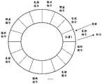
- FIG. 8is an exemplary schematic diagram of a ring buffer according to some embodiments of the present specification.
- FIG. 9is an exemplary flowchart of a method for determining a focus position corresponding to each ultrasonic emission according to some embodiments of the present specification.
- Figure 10ais an exemplary schematic diagram of a linear array ultrasound probe transducer according to some embodiments of the present specification
- Figure 10bis an exemplary schematic diagram of a convex array ultrasound probe transducer according to some embodiments of the present specification
- FIG. 11ais an exemplary schematic diagram of a focal trajectory of ultrasonic emission of a linear array ultrasonic probe according to some embodiments of the present specification
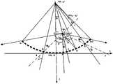
- FIG. 11bis an exemplary schematic diagram of a focal trajectory of ultrasonic emission of a convex array ultrasonic probe according to some embodiments of the present specification
- 13ais an exemplary schematic diagram of determining effective array elements of a convex array ultrasonic probe according to some embodiments of the present specification
- 13bis an exemplary schematic diagram of an effective array element of a linear array ultrasound probe according to some embodiments of the present specification
- FIG. 14is an exemplary flowchart of a method of transmitting transmit pulses according to some embodiments of the present specification.
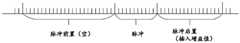
- 15is a schematic diagram of transmit pulse insertion gain values according to some embodiments of the present specification.
- FIG. 16is an exemplary flow chart of obtaining a gain value of an ultrasonic echo signal according to some embodiments of the present specification
- Fig. 17ais a schematic diagram showing the relationship between ultrasonic signal attenuation trend and depth value according to some embodiments of the present specification
- Figure 17bis a schematic diagram of a gain value and a depth value relationship curve according to some embodiments of the present specification.
- FIG. 19is a schematic diagram of transmitting ultrasonic waves based on an effective aperture according to some embodiments of the present specification.
- systemmeans for distinguishing different components, elements, parts, parts or assemblies at different levels.
- devicemeans for converting signals into signals.
- unitmeans for converting signals into signals.
- modulemeans for converting signals into signals.
- FIG. 1is a schematic diagram of an application scenario of an ultrasonic imaging system according to some embodiments of the present specification.
- the ultrasonic imaging system 100can determine the focal locus of ultrasonic emission by implementing the methods and/or processes disclosed in this specification, thereby compensating for the energy loss on both sides of the ultrasonic probe and improving the edge resolution of the ultrasonic image.
- the ultrasonic imaging system 100may include: an ultrasonic probe 110, a processing device 120, a terminal device 130, a network 140, and/or a storage device 150, and the like.
- the components of ultrasound imaging system 100may be connected in one or more of various ways.
- the ultrasound probe 110may be connected to the processing device 120 through a network 140, as shown in FIG. 1a.
- the ultrasound probe 110may be directly connected to the treatment device 120 (as shown by the dashed double-headed arrow connecting the ultrasound probe 110 and the treatment device 120).
- storage device 150may be connected to processing device 120 directly or through network 140 .
- terminal device 130may be connected to processing device 120 directly (as shown by the dashed bidirectional arrow connecting terminal device 130 and processing device 120 ) and/or through network 140 .
- the ultrasound probe 110may acquire scan data. Specifically, the ultrasonic probe 110 can transmit ultrasonic waves to the target object or a part thereof, and receive the reflected ultrasonic waves of the target object or a part thereof.
- the ultrasonic probe 110may include, but is not limited to, a convex array probe, a linear array probe, a phased array probe, a high frequency probe, and the like according to the shape.
- the ultrasonic probe 110may include a piezoelectric ceramic type, a single crystal type, or the like according to piezoelectric materials.
- the processing device 120may process data and/or information obtained from the ultrasound probe 110 , the terminal device 130 and/or the storage device 150 . For example, the processing device 120 may determine the focal position corresponding to each ultrasonic transmission based on the number of transmissions and/or the transmission sequence of the multiple ultrasonic waves to be transmitted. For another example, the processing device 120 may determine the effective array element corresponding to each ultrasonic transmission based on the pointing angle of the array element. For another example, the processing device 120 may also update the inter-frame time based on at least one set of ultrasound imaging history data.
- the processing device 120may include a central processing unit (CPU), a digital signal processor (DSP), a system on a chip (SoC), a microcontroller unit (MCU), the like, and/or any combination thereof. As shown in FIG. 2 , the processing device 120 may include a circuit processing unit 210 , a beamformer 220 and an image former 230 .
- CPUcentral processing unit
- DSPdigital signal processor
- SoCsystem on a chip
- MCUmicrocontroller unit
- the circuit processing unit 210may include an analog front-end circuit, a transmit and receive circuit, an A/D analog-to-digital conversion circuit, and an FPGA controller.
- the analog front-end circuitcan directly apply electrical signal pulses to the ultrasonic probe, and control the ultrasonic probe to emit ultrasonic waves according to the size of the emission aperture determined dynamically each time.
- the analog front-end circuitmay further include a variable gain amplifier for amplifying or suppressing the analog ultrasonic echo signal received by the ultrasonic probe. For more description about the variable gain amplifier, reference may be made to step 730, which is not repeated here.
- the FPGA controllercan acquire control instructions (eg, transmit instructions, gain instructions, receive instructions, and/or idle instructions), and instruct other units or modules to transmit ultrasonic waves, receive ultrasonic echo signals, and acquire ultrasonic waves based on ultrasonic echo signals based on the control instructions image.
- the FPGA controllercan also control the transmit and receive circuits, compress the A/D analog-to-digital converted data, and then transmit the compressed data to the beamformer 220 .
- the beamformer 220may implement signal extraction, signal analysis and/or data interpolation for each ultrasonic echo signal. For more description of the beamformer 220, reference may be made to step 740 and its related descriptions, which will not be repeated here.
- Image former 230may receive information from beam former 220 .
- the image former 230may perform processing such as spatial filtering, image rendering, image compression, and scan conversion on the information from the beamformer.
- processingsuch as spatial filtering, image rendering, image compression, and scan conversion on the information from the beamformer.
- the processing device 120may comprise a computer, a user console, a single server or group of servers, or the like. Server groups can be centralized or distributed.
- processing device 120may be local or remote.
- processing device 120may access information and/or data stored in ultrasound probe 110 , terminal device 130 and/or storage device 150 via network 140 .
- the processing device 120may directly connect to the ultrasound probe 110, the terminal device 130 and/or the storage device 150 to access stored information and/or data.
- the processing device 120may be implemented on a cloud platform.
- cloud platformsmay include private clouds, public clouds, hybrid clouds, community clouds, distributed clouds, inter-cloud, multi-cloud, etc., or any combination thereof.
- the processing device 120 or a portion of the processing device 120may be integrated into the ultrasound probe 110 .
- the terminal device 130may receive instructions (eg, ultrasound examination mode) from the user, and may also display ultrasound images to the user.
- the terminal device 130may include a mobile device 131, a tablet computer 132, a notebook computer 133, etc., or any combination thereof. In some embodiments, terminal device 130 may be part of processing device 120 .
- Network 140may include any suitable network that facilitates the exchange of information and/or data for ultrasound imaging system 100 .
- one or more components of ultrasound imaging system 100eg, ultrasound probe 110 , processing device 120 , storage device 150 , terminal device 130
- the processing device 120may receive user instructions from the terminal device via the network.
- the ultrasound probe 110may acquire ultrasound transmission parameters from the processing device 120 via the network 140 .
- the network 140may be and/or may include a public network (eg, the Internet), a private network (eg, a local area network (LAN), a wide area network (WAN)), a wired network (eg, an Ethernet network), a wireless network (eg, an 802.11 network, Wi- Fi networks), cellular networks (eg, Long Term Evolution (LTE) networks), Frame Relay networks, Virtual Private Networks (“VPNs”), satellite networks, telephone networks, routers, hubs, switches, server computers and/or any of them combination.
- a public networkeg, the Internet
- a private networkeg, a local area network (LAN), a wide area network (WAN)
- a wired networkeg, an Ethernet network
- a wireless networkeg, an 802.11 network, Wi- Fi networks
- cellular networkseg, Long Term Evolution (LTE) networks
- Frame Relay networkseg, Virtual Private Networks (“VPNs”), satellite networks, telephone networks, routers, hub
- the network 140may include a cable network, a wired network, a fiber optic network, a telecommunications network, an intranet, a wireless local area network (WLAN), a metropolitan area network (MAN), a public switched telephone network (PSTN), a Bluetooth TM network, ZigBee TM network, Near Field Communication (NFC) network, etc., or any combination thereof.
- network 140may include one or more network access points.
- network 140may include wired and/or wireless network access points, such as base stations and/or Internet exchange points, through which one or more components of imaging system 100 may connect to network 140 to exchange data and/or or information.
- Storage device 150may store data, instructions and/or any other information.
- storage device 150may store data obtained from ultrasound probe 110 , terminal device 130 , and/or processing device 120 .
- storage device 150may store data and/or instructions that processing device 120 may execute or use to perform the example methods/systems described in this specification.
- storage device 150may include mass storage, removable storage, volatile read-write memory, read-only memory (ROM), the like, or any combination thereof.
- Exemplary mass storagemay include magnetic disks, optical disks, solid state disks, and the like.
- Exemplary removable storagemay include flash drives, floppy disks, optical disks, memory cards, compact disks, magnetic tapes, and the like.
- Exemplary volatile read-write memorymay include random access memory (RAM).
- Exemplary RAMsmay include dynamic random access memory (DRAM), double data rate synchronous dynamic random access memory (DDRSDRAM), static random access memory (SRAM), thyristor random access memory (T-RAM), and zero Capacitive random access memory (Z-RAM), etc.
- Exemplary ROMsmay include masked read only memory (MROM), programmable read only memory (PROM), erasable programmable read only memory (EPROM), electrically erasable programmable read only memory (EEPROM), optical disk only Read-only memory (CD-ROM) and digital versatile disk read-only memory, etc.
- the storage device 150may execute on a cloud platform.
- the cloud platformmay include a private cloud, a public cloud, a hybrid cloud, a community cloud, a distribution cloud, an internal cloud, a multi-layer cloud, etc., or any combination thereof.
- storage device 150may be connected to network 140 to communicate with one or more other components of ultrasound imaging system 100 (eg, ultrasound probe 110, processing device 120, storage device 150, terminal device 130). One or more components of ultrasound imaging system 100 may access data or instructions stored in storage device 150 through network 140 . In some embodiments, storage device 150 may be directly connected to or in communication with one or more other components of ultrasound imaging system 100 (eg, ultrasound probe 110, processing device 120, storage device 150, terminal device 130). In some embodiments, storage device 150 may be part of processing device 120 .
- FIG 3is an exemplary block diagram of an ultrasound imaging system according to some embodiments of the present specification.
- the processing device 120may include an instruction acquisition module 310 , a transmission module 320 , a gain module 330 and an imaging module 340 .
- the instruction acquisition module 310can be used to acquire the transmit instruction, gain instruction, receive instruction and idle instruction of multiple ultrasonic waves to be transmitted, and store the transmit instruction, receive instruction, gain instruction and idle instruction in the ring buffer.
- the instruction fetch module 310may include an issue instruction fetch sub-module 311 .
- the transmission instruction acquisition sub-module 311may be used to acquire the focus position corresponding to each ultrasonic transmission, the effective array element corresponding to each ultrasonic transmission, and/or the transmission pulses of multiple ultrasonic waves.
- the transmission instruction acquisition sub-module 311may include a focus trajectory determination unit 410 , an effective array element determination unit 420 and a transmission pulse acquisition unit 430 .
- the instruction for transmitting multiple ultrasonic wavesmay include a focus position corresponding to each ultrasonic transmission.
- the focus trajectory determination unit 410may be used to determine the focus position corresponding to each ultrasonic emission. As shown in FIG. 5 , the focus trajectory determination unit 410 may include a first relative position determination subunit 510 , a second relative position determination subunit 520 , a focus radius determination subunit 530 and a focus position determination subunit 540 .
- the first relative position determination subunit 510may be configured to determine the first relative position corresponding to each ultrasonic transmission based on the number of times and/or the transmission sequence of the multiple ultrasonic waves to be transmitted, so as to obtain the multiple ultrasonic waves corresponding to the multiple ultrasonic transmissions. a first relative position.
- the first relative position determination subunitreference may be made to step 910, and details are not repeated here.
- the second relative position determination subunit 520may be configured to map the plurality of first relative positions distributed at equal intervals to a plurality of second relative positions distributed at unequal intervals corresponding to the multiple ultrasonic transmissions.
- the second relative position determination sub-unitmay be configured to map the plurality of first relative positions distributed at equal intervals to all the positions distributed at non-equal intervals corresponding to the plurality of ultrasonic transmissions through a nonlinear curve. the plurality of second relative positions.
- the focus radius determination subunit 530may be configured to determine the emission distance and focus radius corresponding to each ultrasonic emission based on the ultrasonic emission parameters and the second relative position corresponding to each ultrasonic emission.
- the ultrasonic emission parametersmay include the number of transducer channels of the transducer, the width of the array element, and the curvature of the transducer.
- the focal radius determination subunit 530may be configured to perform one or more of the following: based on the number of transducer channels, the array element width, and the second relative position, determine the transmission distance corresponding to each ultrasonic transmission; determine the transmission distance corresponding to each ultrasonic transmission, the second relative position corresponding to each ultrasonic transmission and the curvature of the transducer, determine The focal radius corresponding to each ultrasonic emission.
- the focal radius determination subunitmay determine, based on the emission distance corresponding to each ultrasonic emission, the second relative position corresponding to each ultrasonic emission, and the curvature of the transducer, the corresponding ultrasonic emission of each ultrasonic emission.
- the focal position determination subunit 540may determine the focal position corresponding to each ultrasonic emission based on the emission distance and the focal radius corresponding to each ultrasonic emission.
- the focus position determination subunit 540may perform one or more of the following: acquiring each ultrasonic transmission based on the transmission distance and the transducer curvature corresponding to each ultrasonic transmission The corresponding radian of the emission distance; based on the radian corresponding to the emission distance corresponding to each ultrasonic emission, obtain the projection distance of the emission distance corresponding to each ultrasonic emission on the horizontal axis and the vertical axis ; Obtain the abscissa of the focal point corresponding to each ultrasonic emission based on the projection distance on the horizontal axis, the focus radius and the curvature of the transducer corresponding to the emission distance of each ultrasonic emission; The projection distance of the emission distance corresponding to each ultrasonic emission on the vertical axis, the focal point radius and the curvature of the transducer are used to obtain the
- the instruction for transmitting multiple ultrasonic wavesmay include an effective array element (also known as an effective aperture) corresponding to each ultrasonic transmission.
- the effective array element determining unit 420may be used to determine the effective array element corresponding to each ultrasonic transmission.
- the valid array element determination unit 420may include a determination subunit 610 and a determination subunit 620 .
- the judging subunit 610can judge whether there is an invalid array element in the ultrasonic emission. For example, the determination subunit 610 may determine whether the ultrasonic emission has invalid array elements based on the transducer radius, the array element width and/or the focus position corresponding to the ultrasonic emission.
- the judging subunit 610may perform one or more of the following: based on the width of the array element, determine the maximum value of the pointing angle of the array element corresponding to the ultrasonic emission; based on the transducer radius and the maximum value of the pointing angle of the array element value, determine the maximum pointing circle corresponding to the maximum value of the pointing angle of the array element; determine whether the focus position is within the maximum pointing circle; in response to the focus position being within the maximum pointing circle, determine that there is no invalid array element in ultrasonic emission; in response to the focus position not being The maximum point in the circle is to confirm that there are invalid array elements in the ultrasonic emission.
- step 1210For more description of the judging subunit 610, reference may be made to step 1210, which will not be repeated here.
- the determination subunit 620may determine the effective array elements corresponding to the ultrasonic emission. For example, the determining subunit 620 may determine the effective array element corresponding to the ultrasonic emission based on the transducer radius, the width of the array element and/or the focal point in response to the presence of an invalid array element in the ultrasonic emission, or the absence of an invalid array element in response to the ultrasonic emission , all array elements of the transducer are determined as effective array elements.
- the determining subunit 620performs one or more of the following: determining a first deflection angle based on the transducer radius and/or the focal position, the first deflection angle being the transducer center and the focal position The angle between the connecting line of the transducer and the central axis of the transducer; based on the maximum pointing circle, the radius of the transducer and/or the focal position, the second deflection angle is determined, and the second deflection angle is the connection between the center of the transducer and the focal position.
- the angle between the line and the tangent to the maximum pointing circle passing through the focus positionbased on the difference between the first deflection angle and the second deflection angle, determine the first slope of the first connection line between the focus position and the effective array element at the initial left boundary;
- the sum of a deflection angle and a second deflection angledetermines the second slope of the second line connecting the focus position and the initial right boundary effective array element; based on the first slope, the second slope, the transducer radius and/or all array elements , obtain the effective array elements on the left border and the effective array elements on the right border to determine the effective array elements corresponding to ultrasonic emission.
- the determining subunit 620may determine the position of the initial effective array element on the left border and/or the position of the initial effective array element on the right border based on the first slope, the second slope and/or the transducer radius.
- the position of the boundary effective array element and the position of the initial right boundary effective array elementsatisfy the element directivity constraint; in response to determining the position of the initial left boundary effective array element and/or the initial right boundary effective array element is located in all array elements.
- the initial left boundary effective array element and/or the initial right boundary effective array elementare used as the left border effective array element and/or the right border effective array element; in response to determining the position of the initial left border effective array element and/or the initial right border effective array element
- the positions of the boundary effective array elementsare not located within the boundaries of all the array elements, and the boundaries of all the array elements are regarded as the left boundary effective array elements and/or the right boundary effective array elements.
- step 1220, step 1230 and/or step 1240which will not be repeated here.
- the command to transmit multiple ultrasonic wavesmay include multiple transmission pulses of ultrasonic waves.
- the transmission pulse acquisition unit 430may be used to acquire the transmission pulses of multiple ultrasonic waves.
- the transmit pulse acquisition unit 430may perform one or more of the following: dividing at least part of the pulses of the multiple ultrasonic waves to be transmitted into a transmission group, the transmission group including N pulses, wherein N ⁇ 1, each pulse corresponds to at least one of a positive value, a negative value and a zero value; the compressed transmission group is compressed data, and the compressed data is transmitted; decoding is performed based on the received compressed data to obtain at least part of the pulse.
- the transfer groupmay also include at least some of the gain instructions.
- the instruction acquisition module 310may include a gain instruction acquisition sub-module 312 .
- the gain instruction acquisition sub-module 312may perform one or more of the following: determine at least one medium propagation time corresponding to the at least one depth value based on the effective aperture corresponding to the ultrasonic emission and/or at least one depth value of the target object, the at least one medium propagation time corresponding to the at least one depth value.
- a medium propagation timemay include at least one ultrasonic transmitting time and/or at least one ultrasonic receiving time; at least one gain value corresponding to at least one depth value is determined based on the ultrasonic propagation attenuation index, the noise value and/or the at least one medium propagation time.
- the instruction fetch module 310may include an idle instruction fetch sub-module 313 .
- the idle instructionmay control or instruct the ultrasound probe to be in idle time, which may include intra-frame time and/or inter-frame time.
- the idle instruction acquisition sub-module 313can acquire at least one group of ultrasonic imaging historical data based on the trigger condition; acquire historical imaging time based on at least one group of ultrasonic imaging historical data; determine whether the inter-frame time and the historical imaging time meet the preset conditions, the inter-frame time Time is the interval time between transmitting ultrasound corresponding to two adjacent frames of images; in response to the inter-frame time and historical imaging time meeting the preset conditions, the inter-frame time is updated to the historical imaging time; in response to the inter-frame time and historical imaging time not satisfying Preset conditions, do not update interframe time.
- the at least one set of ultrasound imaging history datamay include at least one of ultrasound travel time, imaging time, and image processing time.
- step 710For a detailed description of the instruction obtaining module 310, reference may be made to step 710, which will not be repeated here.
- the transmitting module 320may be configured to acquire the transmitting instructions of multiple ultrasonic waves from the ring buffer, and transmit multiple ultrasonic waves based on the transmitting instructions. In some embodiments, the transmitting module 320 may transmit ultrasonic waves to the target object based on the effective aperture corresponding to the ultrasonic transmission. For a detailed description of the transmitting module 320, reference may be made to step 720, which will not be repeated here.
- the gain module 330may be configured to obtain a gain command and a receiving command for each transmission of multiple ultrasonic waves from the circular buffer, and obtain at least one enhanced echo signal based on the gain command and the receiving command. In some embodiments, the gain module 330 may acquire at least one initial echo signal corresponding to the ultrasonic transmission based on the received instruction. In some embodiments, the gain module 330 may further perform analog gain on at least one initial echo signal corresponding to the ultrasonic transmission based on the gain instruction to obtain at least one enhanced echo signal. For a detailed description of the gain module 330, reference may be made to step 730, which will not be repeated here.
- the imaging module 340may be configured to acquire idle instructions for multiple ultrasound waves from the circular buffer, and based on the idle instructions, process at least one enhanced echo signal to acquire a target ultrasound image.
- the imaging module 340may process the at least one enhanced echo signal within the intra-frame time to acquire ultrasound image information corresponding to each ultrasound transmission.
- processing the at least one enhanced echo signalmay include at least one of signal decimation, signal analysis, and numerical interpolation.
- the imaging module 340may combine the ultrasound image information corresponding to the multiple ultrasound waves within the inter-frame time to obtain initial ultrasound images corresponding to the multiple ultrasound waves.
- Imaging module 340may digitally gain the initial ultrasound image based on at least one gain value.
- the imaging module 340may process the gain initial ultrasound image to obtain the target ultrasound image.
- the processing of the augmented initial ultrasound imagemay include at least one of spatial filtering, image rendering, image compression, and scan conversion.
- FIG. 7is an exemplary flowchart of a method for transmitting ultrasonic waves according to some embodiments of the present specification.
- Ultrasound imagesare images of internal tissues obtained by scanning a target object with ultrasound for medical or medical research, and by receiving and processing the scan data.
- the target objectmay be a human body, an organ, a body, an object, an injury site, a tumor, or the like.
- the target objectmay be one or more diseased tissues in a user's heart.
- the scan dataare ultrasonic echoes received from the target object or a part thereof by transmitting ultrasonic waves to the target object or a part thereof through the ultrasonic probe.
- the format of the ultrasound imagemay include the Joint Photographic Experts Group (JPEG) image format, the Tagged Image File Format (TIFF) image format, the Graphics Interchange Format (GIF) image format, the Kodak Flash PiX (FPX) image format, Digital Imagingand Communications in Medicine (DICOM) image format, etc.
- JPEGJoint Photographic Experts Group
- TIFFTagged Image File Format
- GIFGraphics Interchange Format
- FPXKodak Flash PiX
- DICOMDigital Imagingand Communications in Medicine
- the transduceris an integral part of the ultrasonic probe. It can convert the electrical signal into the ultrasonic signal through the array element (also known as the aperture) to transmit to the target object or a part of it, and can also convert the ultrasonic echo of the target object or a part of it into an electrical signal (i.e. scan data) in order to generate ultrasound images.
- the array elementsmay be piezoelectric materials, such as barium titanate, lead titanate, lead zirconate titanate, and the like.
- the transducermay include array elements of multiple frequencies and a transducer channel (ie, control circuit) corresponding to each array element.
- the transducercan excite the array elements at different positions by the electrical signal through the transducer channel to generate ultrasonic waves of different frequencies. Specifically, the transducer can send each pulse signal to the corresponding transducer channel, and each transducer channel excites the corresponding array element based on the pulse signal, thereby emitting ultrasonic waves of different or the same frequency at different or the same time.
- the array element of the transducerhas three states: transmitting, receiving and idle.
- the three states of the array elementcan be converted through the transmit command, receive command and idle command sent by the FPGA controller respectively.
- the FPGA controllercan also send control commands (ie gain commands) of the variable gainer to process the scan data received by the array element. It can be understood that in the process of acquiring each ultrasonic image, the ultrasonic imaging system needs to continuously switch between the transmitting, gaining, receiving and idle states based on the transmitting command, the gain command, the receiving command and the idle command, resulting in the storage device needing to be continuously stored and taken out. Transmit command, gain command, receive command and idle command.
- the ultrasound imaging method 700may include:
- Step 710Acquire the transmit instruction, gain instruction, receive instruction and/or idle instruction of multiple ultrasonic waves to be transmitted, and store the transmit instruction, receive instruction, gain instruction and/or idle instruction in the ring buffer.
- step 710may be performed by the instruction obtaining module 310 .
- the transmitting instructionis an instruction instructing the ultrasonic probe to transmit one or more ultrasonic waves according to the ultrasonic transmitting parameters.
- the instruction acquisition module 310may acquire the transmit instruction through the transmit instruction acquisition sub-module 311 .
- the ultrasonic emission parametersare parameters used to control ultrasonic emission.
- the ultrasonic emission parametersmay include the number of transducer channels of the transducer, the width of the array element, the curvature of the transducer (transducer radius), and/or the boundary of the array element, and the like.
- the number of transducer channels, array element width, transducer curvature (transducer radius), and array element boundaryplease refer to FIG. 9 , FIG. 12 and related descriptions, which will not be repeated here.
- the instruction for transmitting multiple ultrasonic wavesmay include at least one of a focus position corresponding to each ultrasonic transmission, an effective array element corresponding to each ultrasonic transmission, and/or multiple ultrasonic transmission pulses.
- the focal pointmay be the intersection of the extension lines of the beams emitted by the ultrasonic waves on the target object or a part thereof.
- the transmission instruction acquisition sub-module 311may automatically determine a focus trajectory that is fixedly matched with the ultrasonic probe based on the ultrasonic probe selected by the user. For example, the user selects a linear array ultrasound probe, and the transmitting instruction acquisition sub-module 311 can determine the focus trajectory as shown in FIG. 11a.
- the transmit instruction acquisition sub-module 311may also determine the focus trajectory based on the ultrasound examination mode input by the user. For example, if the user selects "abdominal examination mode", the transmission instruction acquisition sub-module 311 can determine the corresponding convex array ultrasound probe and the focus trajectory as shown in Fig. 12a.
- the transmit instruction acquisition sub-module 311can also use the focus trajectory determination unit 410 to design a focus trajectory that can compensate for energy loss on both sides of the ultrasonic probe based on the ultrasonic transmission parameters, so as to acquire the focus position corresponding to each ultrasonic transmission.
- the focus trajectory determination unit 410can also use the focus trajectory determination unit 410 to design a focus trajectory that can compensate for energy loss on both sides of the ultrasonic probe based on the ultrasonic transmission parameters, so as to acquire the focus position corresponding to each ultrasonic transmission.
- the transducer of the ultrasonic probecan use electrical signals to excite array elements at different positions through the transducer channel, thereby generating ultrasonic waves of different frequencies.
- the effective array elementalso known as the effective aperture
- the effective array elementmay be an array element excited by an electrical signal corresponding to each ultrasonic emission.
- the ultrasonic probemay excite corresponding effective array elements to emit ultrasonic waves based on the focus corresponding to each ultrasonic emission.
- the transmission instruction acquisition sub-module 311may group all the array elements based on the setting parameters input by the user, so as to determine the effective array elements in each group of array elements corresponding to each ultrasonic transmission.
- the ultrasonic probecontains 100 array elements. Based on the group number "5" input by the user, it can be determined that the effective array elements corresponding to the 1st, 2nd, ... 5th ultrasonic transmissions are respectively: the 1st to 20th arrays Elements, the 21st to 31st array elements...the 91st to 100th array elements.
- the transmission instruction acquisition sub-module 311may further determine the effective array element corresponding to each ultrasonic transmission based on the geometric relationship between the directivity of the array element and the focus position through the effective array element determination unit 420 .
- the effective array element determination unit 420may further determine the effective array element corresponding to each ultrasonic transmission based on the geometric relationship between the directivity of the array element and the focus position through the effective array element determination unit 420 .
- the magnitude and direction of the electrical signals that excite the array elements at different positionscan determine the corresponding ultrasonic frequency and magnitude.
- Each group of electrical signalscan consist of multiple pulses.
- the plurality of pulses corresponding to the plurality of ultrasonic waves to be transmittedmay be determined by the processing device 120 based on user instructions obtained from the terminal device 130 .
- the userinputs the ultrasound examination mode "abdominal examination mode" through the terminal device 130, and the processing device 120 may determine a plurality of pulses corresponding to the multiple ultrasound waves to be transmitted based on the "abdominal examination mode".
- the transmit instruction acquisition sub-module 311may acquire corresponding pulses from the processing device 120 .
- the transmit instructionsmay not contain multiple transmit pulses of ultrasound, but instead contain instructions instructing the processing device 120 to transmit corresponding pulses to the ultrasound probe 110 so that the ultrasound probe 110 generates ultrasound based on the pulses.
- the gain instructionmay be an instruction to acquire at least part of the gain parameter of each ultrasonic echo signal emitted by the ultrasonic waves or an instruction to gain the same.
- the gain parametermay be an amplification factor (or gain) that enhances the corresponding ultrasonic echo signal.
- the gain parametermay include at least one of a gain compensation coefficient for analog gain and a gain value for digital gain.
- the gain compensation coefficientcan be the gain parameter of the first-level compensation, which can roughly adjust and amplify the ultrasonic echo signal.
- the gain compensation coefficientreference may be made to step 730, which will not be repeated here.
- the gain valuecan be a gain parameter of the second-level compensation, and can adjust and amplify the ultrasonic echo signal after the first-level compensation more finely.
- only part of the gain parametersmay be stored in the gain command, and another part of the gain parameters may be calculated in real time based on the gain command.
- the gain commandmay store only the gain value, not the gain compensation coefficient, but a command instructing the variable gain amplifier to calculate the gain compensation parameter.
- the gain commandmay only store the gain compensation coefficient and not store the gain value, but store a command instructing the variable gain amplifier to calculate the gain value.
- the receiving instructionmay be an instruction instructing the ultrasonic probe to receive ultrasonic signals reflected from the target object or a portion thereof.
- the receiving instructionmay include the ultrasonic receiving time of each ultrasonic echo and/or the receiving array element receiving each ultrasonic echo. For a detailed description of determining the ultrasonic receiving time and/or the receiving array element, reference may be made to step 1610, which will not be repeated here.
- the idle instructionmay be an instruction instructing the ultrasound probe to suspend transmission and the processing device to acquire an ultrasound image based on the received signal.
- the instruction acquisition module 310may acquire the idle instruction through the idle instruction acquisition sub-module 313 .
- the idle instructionmay control or instruct the ultrasound probe to be in idle time, which may include intra-frame time and/or inter-frame time.
- the intra-frame timemay be the time of transmitting ultrasonic waves corresponding to each frame of image. For example, forming one frame of image may require multiple ultrasonic transmissions, wherein the time between each adjacent two ultrasonic transmissions may be regarded as an intra-frame time.
- the ultrasonic probecan switch between the transmitting state and the receiving state, and the processing device can process the received echo signal to obtain ultrasonic image information.
- the idle instruction acquisition sub-module 313may acquire the intra-frame time based on the ultrasound examination mode input by the user.
- the time between framesmay be the interval time between the ultrasonic transmissions corresponding to two adjacent frames of images.
- the time between the last ultrasonic transmission for forming one frame of image and the first ultrasonic transmission for forming the next frame of imagemay be regarded as the inter-frame time.
- the processing devicemay acquire the ultrasound image based on the ultrasound image information within the inter-frame time.
- the idle instruction acquisition sub-module 313may determine the inter-frame time based on user settings.
- the idle instruction acquisition sub-module 313may also determine the inter-frame time based on historical ultrasound imaging data. For a detailed description of determining inter-frame time determination based on ultrasound imaging history data, reference may be made to FIG. 18 and related descriptions.
- the instruction fetch module 310may store the transmit instruction, the receive instruction, the gain instruction, and/or the idle instruction at any location in the ring buffer in any order, and return the storage location to the processing device 120 for processing Device 120 may invoke any of transmit instructions, receive instructions, gain instructions, and/or idle instructions from the ring buffer over network 140 (eg, an interface) based on the storage location.
- network 140eg, an interface
- the instruction fetch module 310may deposit the issued instruction at "Location 1" in the ring buffer and return the deposit location "Location 1" to the processing device 120 so that the processing device 120 can base the deposit location "Location 1" on the processing device 120. 1", the issue command is called from the ring buffer through the interface.
- Step 720Acquire multiple ultrasonic wave transmitting instructions from the ring buffer, and transmit multiple ultrasonic waves based on the transmitting instruction.
- step 720may be performed by the transmitting module 320 .
- the transmitting module 230may obtain the transmitting instructions of multiple ultrasonic waves from the ring buffer through the network 140 .
- the transmitting module 320can determine the size and/or direction of the electrical signal corresponding to each ultrasonic transmission to excite the effective array element based on the transmitting pulses of multiple ultrasonic waves in the transmitting instruction, and use the electrical signal to excite each time in the transmitting instruction.
- the ultrasonic wavetransmits the corresponding effective array element, so that the effective array element transmits the ultrasonic wave.
- Step 730Obtain the gain command and/or the receiving command for each transmission of the multiple ultrasonic waves from the circular buffer, and obtain at least one enhanced echo signal based on the gain command and/or the receiving command.
- step 730may be performed by the gain module 330 .
- gain module 330may obtain gain instructions and/or receive instructions for each transmission of multiple ultrasound waves from a ring buffer via network 140 .
- the gain module 330may acquire at least one initial echo signal corresponding to the ultrasonic transmission from the receiving array element specified in the receiving instruction based on the receiving instruction. Specifically, the gain module 330 can use the receiving array element to receive ultrasonic echoes transmitted from the target object or a part thereof, and convert the mechanical vibrations generated by the ultrasonic echoes connected to the receiving array elements into electrical signals, ie, initial echo signals.
- the gain module 330may perform an analog gain on at least one initial echo signal corresponding to the ultrasonic transmission based on the gain command to obtain at least one enhanced echo signal. Specifically, the gain module 330 may obtain the gain compensation coefficient through the variable gain amplifier. Specifically, the gain command obtaining sub-module 312 may determine the gain compensation coefficient corresponding to each ultrasonic echo signal based on the ultrasonic transmission time corresponding to each ultrasonic transmission and/or the ultrasonic receiving time of each ultrasonic echo signal. For a detailed description of the ultrasonic transmission time and the ultrasonic reception time, reference may be made to step 1610, which will not be repeated here.
- the instruction acquisition module 310may calculate the time difference between the ultrasonic emission time corresponding to each ultrasonic wave and/or the ultrasonic receiving time of one of the corresponding ultrasonic echo signals and the reference time difference threshold or The threshold range is compared, and the analog gain compensation coefficient corresponding to the ultrasonic echo signal is obtained.
- a certain transmitted ultrasonic wavemay correspond to multiple ultrasonic echo signals, and the time difference between the ultrasonic transmission time corresponding to the certain ultrasonic transmission and the ultrasonic receiving time corresponding to the i-th ultrasonic echo signal in the corresponding ultrasonic echo signals is ti, when ti is less than the reference time difference threshold T, the analog gain compensation coefficient corresponding to the ultrasonic echo signal is determined to be k1; when ti1 is greater than the reference time difference threshold T, then the analog gain compensation coefficient corresponding to the ultrasonic echo signal is determined is k2, where k1 and k2 can be set based on empirical values.
- the instruction acquisition module 310may also determine the analog gain compensation coefficient corresponding to the ultrasonic echo signal based on the time difference corresponding to the ultrasonic echo signal and the time difference corresponding to the two previous ultrasonic echo signals.
- variable gain amplifiermay multiply each initial echo signal by each corresponding gain compensation coefficient contained in the gain command, thereby obtaining each corresponding enhanced echo signal.
- the gain compensation coefficientmay also be stored in the gain command of the ring buffer by the gain command obtaining sub-module in advance, and the variable gain amplifier may obtain the gain compensation coefficient based on the gain command to perform analog gain on the ultrasonic echo signal.
- Step 740Acquire multiple ultrasound idle commands from the circular buffer, and process at least one enhanced echo signal based on the idle commands to obtain a target ultrasound image.
- step 740may be performed by the imaging module 340 .
- the imaging module 340may process at least one enhanced echo signal within the frame time to acquire ultrasound image information corresponding to each ultrasound transmission.
- the ultrasound image informationis the image representation information of the ultrasound echo signal, which can be expressed in different forms based on different ultrasound imaging methods.
- each ultrasonic image information corresponding to the A-type ultrasonic imaging modemay be expressed as the relationship between the amplitude of at least one enhanced echo signal corresponding to each ultrasonic transmission and the ultrasonic receiving time.
- each ultrasonic image information corresponding to the B-mode ultrasonic imaging methodmay be expressed as the relationship between the position depth of the target object or a part thereof reached by each ultrasonic wave and the intensity of the enhanced echo signal reflected from the position depth.
- multiple ultrasonic wavesmay be transmitted within the frame time corresponding to each frame of image, and during the interval between two adjacent ultrasonic waves, the imaging module 340 may process the ultrasonic waves corresponding to the last transmitted ultrasonic waves in the two adjacent ultrasonic waves. At least one enhanced echo signal is used to obtain corresponding ultrasound image information. For example, 20 ultrasonic waves are transmitted within the frame time corresponding to a certain frame of image, and the imaging module 340 can process at least one enhanced echo corresponding to the first ultrasonic wave during the interval between the emission of the first ultrasonic wave and the second ultrasonic wave. wave signal to obtain the ultrasound image information corresponding to the first ultrasound.
- the imaging module 340can first convert the analog enhanced echo signal into a digital enhanced echo signal through an A/D analog-to-digital conversion circuit, and then transmit the compressed digital enhanced echo signal to the beamformer, The at least one enhanced echo signal is then processed by a beamformer.
- processing the at least one enhanced echo signalmay include at least one of signal decimation, signal analysis, and/or numerical interpolation.
- Signal extractionmay be the process of decompressing a compressed transmission signal.
- the A/D analog-to-digital conversion circuitcompresses the enhanced echo signal and transmits it to the beamformer, which then decompresses the enhanced echo signal through signal extraction.
- Signal analysismay be a process of improving the quality of the enhanced echo signal based on the features of the enhanced echo signal.
- the imaging module 340may perform signal analysis on the enhanced echo signals through filters and/or machine learning models.
- the filtersmay include, but are not limited to, at least one or a combination of low-pass filtering (smoothing), high-pass filtering (sharpening), and band-pass filtering.
- machine learning modelsmay include, but are not limited to, Convolutional Neural Network (CNN) models, Deep Neural Network (CNN) models, and Recurrent Neural Network (RNN) models Wait.
- CNNConvolutional Neural Network
- CNNDeep Neural Network
- RNNRecurrent Neural Network
- Numerical interpolationcan be the process of interpolating a signal.
- the numerical interpolationmay include, but is not limited to, at least one of adaptive interpolation algorithms such as nearest neighbor interpolation, quadratic interpolation, cubic interpolation, and the like.
- the imaging modulemay obtain interpolation between two adjacent enhanced echo signals based on the two adjacent enhanced echo signals. For example, the first ultrasonic wave is transmitted corresponding to 3 enhanced echo signals, and the imaging module can obtain the interpolation between the first and second enhanced echo signals based on the first and second enhanced echo signals, based on the second The first and third enhanced echo signals obtain interpolation between the second and third enhanced echo signals, thereby inserting 2 interpolations into the 3 enhanced echo signals.
- the imaging module 340may combine ultrasound image information corresponding to multiple ultrasound waves within an inter-frame time to obtain an initial ultrasound image corresponding to multiple ultrasound waves.
- the imaging module 340may first combine multiple ultrasound image information corresponding to each frame of images to obtain an initial ultrasound image frame, and then combine multiple initial ultrasound image frames after the last ultrasound is transmitted to obtain multiple initial ultrasound images corresponding to ultrasound waves .
- the imaging module 340may first composite 20 ultrasonic waves corresponding to the 20 ultrasonic waves transmitted in the i-th intra-frame time during the inter-frame time between the i-th intra-frame time and the i+1-th intra-frame time.
- Ultrasound image informationobtain the ith initial ultrasonic image frame; then after the last intra-frame time, composite N initial ultrasonic image frames corresponding to N intra-frame times: the 1st initial ultrasonic image frame, ... the i-th initial frame Ultrasound image frame, ... the Nth frame of the initial ultrasound image frame, to obtain the initial ultrasound image corresponding to N ⁇ 20 times of ultrasound.
- the imaging module 340may determine the corresponding imaging coordinates based on the ultrasound imaging method, and then fuse the information of multiple ultrasound images into the same imaging coordinates to obtain an initial ultrasound image.
- the imaging module 340may perform a digital gain on the initial ultrasound image based on the at least one gain value. In some embodiments, the imaging module 340 may multiply the corresponding gain value by the signal intensity corresponding to each point in the initial ultrasound image. For example, point A can indicate that the signal amplitude at the depth h1 of the target object is 20, then the gain value ⁇ (h1) corresponding to the depth h of the target object can be multiplied by 20 to obtain the signal strength after the gain at this point.
- the imaging module 340may process the gain initial ultrasound image through the image former 230 to obtain the target ultrasound image.
- the method of processing the gain initial ultrasound imagemay include at least one of spatial filtering, image rendering, image compression, and scan conversion.
- Spatial filteringmay be the use of filtering to enhance the quality of the initial ultrasound image.
- spatial filteringmay include, but is not limited to, at least one of low-pass filtering (smoothing), high-pass filtering (sharpening), bandpass filtering, a 3x3 adaptive filtering algorithm, and a 5x5 adaptive filtering algorithm or its combination.
- Image renderingcan be a process of converting three-dimensional energy transfer into two-dimensional images, and can convert digitally enhanced echo signals into image information.
- the manner of image renderingmay include, but is not limited to, at least one of OpenGL, DirectX, etc., or a combination thereof.
- Image compressionmay be to reduce the amount of initial ultrasound image data.
- the image compression methodmay include, but is not limited to, a combination of at least one or more of differential pulse code modulation method, hierarchical interpolation method, differential pyramid method, multiple autoregressive method and discrete cosine transform, etc. .
- Scan conversionmay be to convert the original ultrasound image to the ultrasound image in the target coordinate system. For example, convert an initial ultrasound image in polar coordinates to Cartesian coordinates.
- Some embodiments of this specificationcan directly store the control commands (transmit command, gain command, receive command and/or idle command) in any position in the ring buffer in any order, and can store the control commands from the ring buffer based on the storage position of the control command.
- the specified control instructionis taken out of the buffer for execution, thereby avoiding frequent memory allocation and release, reducing system overhead and memory fragmentation, thereby improving system operation efficiency.
- FIG. 9is an exemplary flowchart of a method for determining a focus position corresponding to each ultrasonic transmission according to some embodiments of the present specification.
- each frame of ultrasound imagemay be acquired based on scan data corresponding to multiple ultrasound transmissions.
- each ultrasonic wavecorresponds to a focal point during transmission, and the focal point is the intersection point of the beam extension lines of the corresponding ultrasonic wave emission on the target object or a part thereof. It can be understood that the greater the number of focal points corresponding to the target object or a part thereof, that is, the more ultrasonic beams emitted to the target object or a part thereof, the higher the resolution of the ultrasound image of the target object or a part thereof.
- a focus trajectory of the ultrasonic wave emission with dense focus on both sidescan be designed.
- a focal trajectory for transmitting ultrasonic waves with a dense intermediate focuscan be designed to improve the ultrasonic image resolution of the deep target object.
- the ultrasonic transmission method 900may include one or more of the following operations.
- Step 910Determine the first relative position corresponding to each ultrasonic transmission based on the number of times and/or the transmission sequence of the multiple ultrasonic waves to be transmitted, so as to obtain multiple first relative positions corresponding to the multiple ultrasonic transmissions.
- step 910may be performed by the first relative position determination subunit 510 .
- the multiple ultrasound waves to be transmittedmay be multiple ultrasound waves corresponding to each frame of the ultrasound image.
- the multiple ultrasonic waves to be transmittedmay be in a non-focused transmission mode.
- the non-focused emission moderefers to an emission mode in which the corresponding focus of ultrasonic waves is not in the imaging area during emission. For example, plane wave emission mode, divergent wave emission mode, wide beam emission mode, etc.
- the transmission times of the multiple ultrasonic waves to be transmittedmay be the ultrasonic transmission times corresponding to each frame of the ultrasonic image. For example, if the number of transmissions is 10, each frame of ultrasound image is generated based on scan data of ultrasonic reflections transmitted 10 times to the target object or a part thereof.
- the first relative position determination subunit 510may determine the number of shots based on the ultrasound examination mode (eg, abdominal examination mode, blood vessel examination mode, thyroid examination mode, etc.) input by the user. For example, the first relative position determination subunit 510 may determine that the number of transmissions is 10 based on the ultrasound examination mode "abdominal examination mode" input by the user. In some embodiments, the first relative position determination subunit 510 may also directly acquire the number of transmissions input by the user.
- the ultrasound examination modeeg, abdominal examination mode, blood vessel examination mode, thyroid examination mode, etc.
- the first relative position determination subunit 510may also directly acquire the number of transmissions input by the user.
- the transmission sequence of the multiple ultrasonic waves to be transmittedconsists of the sequence of each ultrasonic transmission in the multiple ultrasonic waves.
- the firing order of each ultrasonic wavecan be represented numerically.
- the transmission sequence of the 10 ultrasonic waves to be transmittedcan be 0, 1, 2...8, 9, respectively representing the first ultrasonic emission, the second ultrasonic emission, the third ultrasonic emission...the ninth ultrasonic emission, the third ultrasonic emission Ultrasonic waves were fired ten times.
- the first relative positionmay be the relative position when the centers of the array elements on the ultrasonic probe corresponding to the focal points of the ultrasonic waves corresponding to the emission order are distributed at equal intervals.
- the relative positionrefers to the position distribution in which the distance from the center of the array element corresponding to the transmitting order to the center of the ultrasonic probe (ie, the transmitting distance) is mapped to a certain range.
- the transmission distanceFor a detailed description of the transmission distance, reference may be made to step 930, which will not be repeated here.
- the first relative positionmay represent a position distribution with a value between [-1, 1].
- the focal points corresponding to the multiple ultrasonic transmissionsmay include the focal point A corresponding to the ultrasonic wave transmitted in the first time and the focus point B corresponding to the ultrasonic wave transmitted in the second time.
- the first relative position corresponding to the ultrasonic wavethat is, the distance A'O between the center A' of the array element corresponding to the focus A and the center O of the ultrasonic probe is mapped to the value between [-1, 1]
- the ultrasonic wave corresponding to the second transmissionis
- the first relative positionthat is, the distance B'O between the center B' of the array element corresponding to the focus B and the center O of the ultrasonic probe is mapped to a value between [-1, 1].
- the first relative positionis less than 0, it means that the ultrasonic waves corresponding to the emission order are being emitted, and the focus is on the left side of the center of the ultrasonic probe.
- the focusis to the right of the center of the ultrasound probe. Further, the closer the first relative position is to -1 or 1, the closer the focus is to the edge of the ultrasonic probe when the ultrasonic waves corresponding to the emission order are emitted; the closer the first relative position is to 0, the ultrasonic waves corresponding to the emission order are When transmitting, the focus is closer to the center of the ultrasound probe.
- the first relative positionmay also reflect the relative position of the corresponding energy distribution of the ultrasound waves of each transmission order in the ultrasound image frame. For example, the closer the first relative position is to -1 or 1, the closer the energy distribution of the ultrasound waves corresponding to the emission order in the ultrasound image frame is to the edge of the image; the closer the first relative position is to 0, the closer The corresponding energy distribution of ultrasound in the ultrasound image frame is closer to the middle of the image.
- the first relative positionmay be determined by equation (1):
- nrepresents the number of times of ultrasonic waves to be transmitted
- irepresents the sequence of each ultrasonic transmission
- ⁇ irepresents the first relative position corresponding to the ith transmitted ultrasonic waves, ⁇ i ⁇ [- 1,1].
- the emission distances corresponding to the centers of the corresponding array elements distributed at equal intervalscan be calculated, thereby further calculating the focal positions distributed at equal intervals.
- the ultrasonic waves emitted based on the focal position distributed at equal intervalscannot solve the uneven distribution of ultrasonic image resolution caused by the scattering on both sides of the ultrasonic probe. Therefore, it is necessary to further obtain the emission distances corresponding to the centers of the array elements distributed at uneven intervals, so as to further calculate The focal positions are distributed at unequal intervals.
- Step 920Map the plurality of first relative positions distributed at equal intervals to a plurality of second relative positions distributed at unequal intervals corresponding to the multiple ultrasonic transmissions.
- step 920may be performed by the second relative position determination subunit 520 .
- the second relative positionis the relative position when the centers of the array elements on the ultrasonic probe corresponding to the focal points of the ultrasonic waves corresponding to the emission order are distributed at unequal intervals when the ultrasonic waves are emitted.
- the corresponding multiple ultrasonic wavesare uniformly emitted from the ultrasonic probe.
- the lower the resolution of the corresponding position in the frameie the position of the edge of the ultrasound image frame.
- the second relative position determination subunit 520may map the relative positions of the focal points distributed at equal intervals to distribution at non-equal intervals. Specifically, the second relative position determination subunit 520 may set more focal points at the position where the ultrasonic energy loss is greater, that is, the relative position interval of the plurality of focal points is made smaller.
- the second relative position determination subunit 520may map a plurality of first relative positions distributed at equal intervals to a plurality of second relative positions distributed at unequal intervals corresponding to the multiple ultrasonic transmissions through a nonlinear curve relative position.
- the nonlinear curvecan be represented by equation (2):
- irepresents the sequence of each ultrasonic transmission
- ⁇ irepresents the first relative position corresponding to the ith transmitted ultrasonic wave
- Wirepresents the second relative position corresponding to the ith transmitted ultrasonic wave.
- the second relative position determination subunit 520can use the curve (2) to determine the first ultrasonic emission corresponding to the 0th, 1st, 2nd, . . . 7th, 8th, and 9th ultrasonic transmissions Relative positions -1, -7/9, -5/9, ... 5/9, 7/9, 1 are mapped to the second relative positions 1, -679/729, -545/729, ... 545/729, 679 respectively /729, 1, with intervals of 50/729, 134/729, ..., 134/729, 50/729.
- the second relative positionmay also reflect the relative position of the corresponding energy distribution of the ultrasound waves of each transmission order in the ultrasound image frame. For example, the closer the second relative position is to -1 or 1, the closer the energy distribution of the ultrasonic waves corresponding to the emission order in the ultrasound image frame is to the edge of the image; the closer the second relative position is to 0, the closer The corresponding energy distribution of ultrasound in the ultrasound image frame is closer to the middle of the image.
- multiple first relative positions distributed at equal intervals corresponding to multiple ultrasonic waves to be transmittedare mapped to multiple second relative positions distributed at unequal intervals through a curve, so that multiple ultrasonic waves corresponding to multiple The relative positions between the focal points are more densely distributed on both sides, thereby compensating for the lower resolution at the edges of the ultrasound image caused by energy loss on both sides of the ultrasound probe.
- Step 930Determine the emission distance and focus radius corresponding to each ultrasonic emission based on the ultrasonic emission parameters and/or the second relative position corresponding to each ultrasonic emission.
- step 930may be performed by the focus radius determination subunit 530 .
- the ultrasonic emission parametersare parameters used to control ultrasonic emission.
- the ultrasonic emission parametersmay include the number of transducer channels of the transducer, the width of the array element, and/or the curvature of the transducer.
- the number of transducer channelsis the number of transducer channels (control circuits). In some embodiments, each transducer channel may excite one array element. For example, if the number of transducer channels is 20, 20 array elements can be excited.
- the array element widthis the cross-sectional width of the array element.
- the width of the array element of the transducer of the linear array ultrasonic probe(represented by a short black line in the figure) is d1 (such as 0.00003 meters).
- the width of the array element of the transducer of the convex array ultrasonic probe(represented by the black short line segment in the figure) is d2 (eg 0.000452 meters).
- the transducer curvatureis the reciprocal of the transducer radius, a parameter that can characterize the degree of curvature of the array elements on the transducer.
- the greater the transducer curvaturethe greater the degree of curvature of the transducer array element arrangement (that is, the more convex the transducer), and the smaller the transducer radius; the smaller the transducer curvature, the greater the transducer array element arrangement.
- the smaller the degree of curvatureie, the flatter the transducer
- the transducer array elements of the linear array ultrasonic probeare arranged in a straight line, and the transducer curvature of the linear array ultrasonic probe is 0.
- the emission distanceis the distance between the center of the array element corresponding to the focal point of the ultrasonic wave corresponding to the emission order and the center of the ultrasonic probe.
- the multiple transmission distances corresponding to multiple ultrasonic transmissionsmay include line segments A'O and B'O, where A'O represents the ultrasonic array element corresponding to the emission focus A The distance between the center A' and the center O of the ultrasonic probe, and B'O represents the distance between the ultrasonic array element center B' corresponding to the emission focus B and the center O of the ultrasonic probe.
- A'Orepresents the ultrasonic array element corresponding to the emission focus A
- B'Orepresents the distance between the ultrasonic array element center B' corresponding to the emission focus B and the center O of the ultrasonic probe.
- the multiple transmission distances corresponding to multiple ultrasonic transmissionsmay include arc lengths and in, Represents the distance between the ultrasonic array element center C' corresponding to the emission focus C and the ultrasonic probe center O, Indicates the distance between the ultrasonic array element center D' corresponding to the emission focus D and the ultrasonic probe center O.
- the focal radius determination subunit 530may determine the transmission distance corresponding to each ultrasonic transmission based on the number of transducer channels, the array element width and the second relative position corresponding to each ultrasonic transmission.
- the focal radius determination subunit 530may determine the emission distance corresponding to each ultrasonic emission based on formula (3):
- Nrepresents the number of transducer channels
- D srepresents the width of the array element
- Phy irepresents the emission distance corresponding to the ith transmitted ultrasonic wave.
- Some embodiments of the present specificationacquire unequally spaced emission distances on the ultrasound probe corresponding to the centers of the plurality of array elements corresponding to the plurality of focal points based on the plurality of unequally spaced second relative positions.
- the focal radiusis the radius of the close circle of the focal point on the focal locus, which can reflect the degree of curvature of the focal locus.
- the focal radius determination subunit 530may determine the focal radius corresponding to each ultrasonic transmission based on the transmission distance corresponding to each ultrasonic transmission, the second relative position corresponding to each ultrasonic transmission and/or the curvature of the transducer .
- the focus radius determination subunit 530may determine the focus curvature corresponding to each ultrasonic transmission based on the transmission distance corresponding to each ultrasonic transmission, the second relative position corresponding to each ultrasonic transmission and/or the transducer curvature.
- the focal curvatureis the inverse of the focal radius.
- the focal radius determination subunit 530may determine the focal curvature corresponding to each ultrasonic emission based on formula (4):
- irepresents the sequence of each ultrasonic emission
- FK irepresents the focal curvature corresponding to the ultrasonic wave emitted at the i-th time
- krepresents the transducer curvature
- ConstKrepresents the ultrasonic emission constant
- the ConstKcan be adjusted based on empirical values, For example ConstK can be -0.04.
- the focus radius determination subunit 530may determine whether the focus curvature corresponding to each ultrasonic emission is smaller than the curvature threshold.
- the curvature thresholdmay be the minimum value of the focal curvature corresponding to each ultrasonic emission.
- the curvature thresholdmay be one.
- the reciprocal of the curvature thresholdis used as the value of the focus radius, and the direction of the focus radius is determined based on the focus curvature. For example, if the focus curvature FK 1 corresponding to the first ultrasonic emission is -0.5, the curvature threshold 1 is taken as the value of the corresponding focus curvature, the reciprocal 1 of the curvature threshold 1 is taken as the value of the focus radius, and based on the corresponding focus curvature FK 1 (eg -0.5), the direction of determining the focal radius is negative, that is, the focal radius FR1 is -1 .
- the inverse of the focus curvatureis used as the focus radius. For example, if the absolute value of the focus curvature FK 2 -2 corresponding to the second ultrasonic emission is 2, which is greater than the curvature threshold value of 1, the reciprocal -0.5 of the focus curvature -2 is used as the focus radius FR 2 .
- the focal radius determination subunit 530may determine the focal radius corresponding to each ultrasonic emission based on formula (5):
- irepresents the sequence of each ultrasonic transmission
- FR irepresents the focal radius corresponding to the ith transmitted ultrasonic wave
- arepresents the curvature threshold
- sgn(FK i )represents the symbol for obtaining FK i .
- Some embodiments of the present specificationacquire the focus radius based on the second relative position, so that the larger the value of the second relative position, that is, the farther the second relative position is from the middle position of the ultrasonic probe, the greater the absolute value of the focus curvature; further Specifically, when the absolute value of the focus curvature is greater than the curvature threshold, the value of the corresponding focus radius is smaller, and the interval between the values of the corresponding focus radius is smaller, so that step 840 determines the horizontal and vertical dimensions of the focus position based on the focus radius and the emission distance.
- the coordinatesare further related to the second relative position; at the same time, when the absolute value of the focus curvature is less than the curvature threshold (that is, the transducer is a linear array transducer), the value of the focus radius does not change, so that step 840 determines based on the emission distance Only the abscissa of the focus position is further related to the second relative position.
- the curvature thresholdthat is, the transducer is a linear array transducer
- Step 940Determine a focus position corresponding to each ultrasonic emission based on the emission distance and the focus radius corresponding to each ultrasonic emission.
- step 940may be performed by the focus position determination subunit 540 .
- the focal trajectory of the multiple ultrasonic waves to be transmittedcan be determined.
- the focal position determination subunit 540may obtain the radian corresponding to the emission distance corresponding to each ultrasonic emission based on the emission distance corresponding to each ultrasonic emission and the curvature of the transducer.
- the radian corresponding to the emission distance corresponding to each ultrasonic emissionis the ratio of the emission distance Phy i corresponding to each ultrasonic emission to the radius of curvature of the transducer, that is, the emission distance Phy i corresponding to each ultrasonic emission and the transducer Product of curvature k, i.e. Phy i *k.
- the focus position determination subunit 540may obtain the projection distance of the emission distance corresponding to each ultrasonic emission on the horizontal axis and the vertical axis based on the radian corresponding to the emission distance corresponding to each ultrasonic emission. Specifically, the focus position determination subunit 540 may obtain the projection distances sin(Phy i *k) and cos(Phy i *k) of the emission distance corresponding to each ultrasonic emission on the horizontal axis and the vertical axis, respectively.
- the focus position determination subunit 540can obtain the abscissa of the focus corresponding to each ultrasonic emission based on the projection distance on the horizontal axis, the focus radius and/or the transducer curvature of the emission distance corresponding to each ultrasonic emission. ; Based on the projection distance of the emission distance corresponding to each ultrasonic emission on the vertical axis, the focal point radius and/or the curvature of the transducer, obtain the ordinate of the focal point corresponding to each ultrasonic emission.
- the focal position determination subunit 540may determine the abscissa and ordinate of the focal point corresponding to each ultrasonic emission based on formula (6):
- irepresents the sequence of each ultrasonic emission
- fx i and fz irepresent the abscissa and ordinate of the focus corresponding to the ith ultrasonic emission, respectively
- FR irepresents the ith ultrasonic emission corresponding to the Focus radius.
- the focus trajectory of the multiple ultrasonic waves to be transmittedis It can be seen from the foregoing that the larger the absolute value of the second relative position corresponding to the ultrasonic sequence (that is, the farther the distance from the middle position of the ultrasonic probe), the larger the absolute value of the corresponding unequally spaced emission distance, and the smaller the interval, That is, the larger the absolute value of the abscissa, the smaller the interval; when the absolute value of the focus curvature is less than the curvature threshold (that is, the transducer is a linear array transducer), the value of the focus radius does not change, which is the reciprocal of the curvature threshold 1 /a, the direction of the focus radius is determined based on the direction of the focus curvature, that is, the ordinate is sgn(FK i )1/a.
- the focal points on the horizontal axisare denser as they are farther from the origin, thereby compensating for the greater energy loss on both sides of the ultrasonic probe, while the absolute value of the focal points on the vertical axis (Z-axis) is close to to a value of 0.
- the focus trajectory of the multiple ultrasonic waves to be transmittedis further related to the emission distance and the transducer curvature corresponding to each ultrasonic transmission.
- the focal points on the horizontal axis (X-axis)are denser as they are farther and closer to the origin, thereby compensating for the greater energy loss on both sides of the ultrasonic probe, while improving the target of the convex array ultrasonic probe in the depths.
- FIG. 12is an exemplary flowchart of determining the effective array element corresponding to each ultrasonic transmission according to some embodiments of the present specification.
- ultrasonic waveswill also be scattered in the process of propagating from the ultrasonic probe to the target object or a part thereof, so that part of the ultrasonic beam cannot reach the target object or a part thereof, resulting in energy loss. , reducing the resolution of the ultrasound image. Therefore, in order to enhance the ultrasonic energy reaching the target object, that is, to increase the number of ultrasonic beams transmitted to the target object or a part thereof, the effective array element corresponding to each ultrasonic emission can be determined, so that the ultrasonic beams emitted by each effective array element can be exhausted. May reach the target object or a part thereof.
- the method 1200 for determining the effective array element corresponding to each ultrasonic transmissionmay include:
- Step 1210based on the transducer radius, the width of the array element and/or the focal position corresponding to the ultrasonic emission, determine whether the ultrasonic emission has invalid array elements.
- step 1210may be performed by the judging subunit 610 .
- An invalid array elementmay refer to an array element on which the transmitted ultrasonic beam cannot reach the target object or a part thereof.
- the ultrasonic beam emitted by the array element ais scattered during the propagation process, so that the ultrasonic beam cannot reach the target object or a part thereof along the scattered propagation direction, then the array element a is an invalid array element.
- the judging subunit 610may determine the maximum value of the pointing angle of the array element corresponding to the ultrasonic emission based on the width of the array element, and determine the maximum value of the pointing angle of the array element based on the transducer radius and the maximum value of the pointing angle of the array element. The value corresponds to the largest pointing circle.
- the array elements in the ultrasonic probehave directivity, that is, the ultrasonic waves emitted by the array elements can propagate along a specified direction.
- the range of the specified directionmay be represented by the pointing angle of the array element.
- the array element pointing angle of the convex array ultrasonic probecan take the array element as the vertex and the angle between the center of the transducer and the array element as a side, which can indicate that the ultrasonic beam emitted by the array element is in the Directional propagation within the included angle range.
- the pointing angle of the array element corresponding to the array element ais the angle ⁇ 1 with the array element a as the vertex and the connection line between the transducer center P and the array element a as one side, It can represent the propagation direction of the ultrasonic wave emitted by the array element a within the range of the included angle ⁇ 1.
- the other side of the array element pointing anglemay be on the left and/or right side of the line connecting the center of the transducer and the array element, and the array element pointing angles at different positions may correspond to different focal positions.
- the pointing angle of the array element of the linear array ultrasonic probemay be the angle between the line connecting the focal point corresponding to the ultrasonic emission and the array element and the central axis of the transducer.
- the array element pointing angle corresponding to the array element cis the clip between the connecting line F i c between the focal point F i corresponding to the ultrasonic emission and the array element c and the central axis of the transducer
- the angle ⁇ 3can represent the propagation direction of the ultrasonic wave emitted by the array element c within the range of the included angle ⁇ 3.
- the maximum value of the array element pointing angle corresponding to ultrasonic emissionneeds to satisfy formula (7):
- ⁇is the maximum value of the pointing angle of the array element corresponding to the ultrasonic emission
- ⁇is the wavelength of the ultrasonic wave
- dis the width of the array element of the ultrasonic probe.
- the maximum pointing circle corresponding to the maximum value of the array element pointing angle of the convex array ultrasonic probemay be a circle with the center of the transducer as the center and the product of the maximum value of the array element pointing angle and the transducer radius as the radius. At this time, the other side of the array element pointing angle is the tangent of the maximum pointing circle.
- PLis the vertical line on the extension line of Pa passing through the point P.
- Pais the hypotenuse
- the lengthis the radius of the transducer
- the judging subunit 610can judge whether the focus position is within the maximum pointing circle, and in response to the focus position being within the maximum pointing circle, determine that there is no invalid array element for ultrasonic emission; in response to the focus position being not within the maximum pointing circle, determine that There are invalid array elements in ultrasonic transmission.
- the judging subunit 610can compare the distance from the focus position to the center of the circle and the radius of the maximum pointing circle by formula (8), so as to judge whether the focus position is within the maximum pointing circle:
- x p and z pare the abscissa and ordinate of the focus position, respectively, and z R is the center of the transducer circle.
- the absolute value of z Ris the transducer radius R, That is, the distance from the focus position to the center of the circle.
- the effective array element corresponding to the ultrasonic emissioncan be determined based on step 1230 .
- the focus Fjis on the radius PL of the maximum pointing circle, and based on the fact that the length of PFj is smaller than the radius of the maximum pointing circle, the focus Fj satisfies the formula (8).
- the effective array elements corresponding to the ultrasonic emissioncan be determined based on step 1220. As shown in Figure 13a, the focus Fi is on the tangent of the maximum pointing circle (ie, the other side of the maximum pointing angle). Based on the fact that the length of PFi is greater than the radius of the maximum pointing circle, the focus Fi does not satisfy formula (8).
- the linear array ultrasonic probecan be regarded as a convex array ultrasonic probe with the transducer center at infinity, that is, the transducer radius R is infinite, and the effective array element corresponding to the ultrasonic emission can be determined directly based on step 1220 .
- Step 1220in response to the presence of an invalid array element in the ultrasonic emission, determine an effective array element corresponding to the ultrasonic emission based on the transducer radius, the array element width and/or the focus position.
- step 1220may be performed by the determination subunit 620 .
- the ultrasonic beam emitted by the effective array elementcan reach the target object or a part thereof.
- the ultrasonic beam emitted by the array element ais scattered during the propagation process, but the ultrasonic beam can still reach the target object or a part thereof along the scattered propagation direction, then the array element a is an effective array element.
- the determination subunit 620may determine the first deflection angle based on the transducer radius and/or the focus position.
- the first deflection anglemay be the included angle between the line connecting the center of the transducer and the focal position and the central axis of the transducer.
- the angle ⁇ 0 between the line PFi connecting the center P of the transducer circle and the focal position Fi of the convex array ultrasonic probe and the central axis PO of the transduceris the first deflection angle.
- the determining subunit 620may determine the first deflection angle ⁇ 0 based on the opposite side Q Fi and the adjacent side PQ of ⁇ 0 in the right triangle PQFi.
- the value of the opposite side Q Fiis the difference between the transducer radius and the ordinate of the focus position
- the value of the adjacent side PQis the abscissa of the focus position.
- the determination subunit 620can obtain the first deflection angle ⁇ 0 by formula (9).
- the center P of the transducer of the linear array ultrasonic probeapproaches infinity, and the radius of the transducer approaches infinity, then the connection line PFi between the center P of the transducer of the linear array ultrasonic probe and the focal position Fi and
- the angle between the central axes PO of the transducers, ie the first deflection angle ⁇ 0is equal to 0°.
- the determination subunit 620may determine the second deflection angle based on the largest pointing circle, the transducer radius, and/or the focal point position.
- the second deflection anglemay be the included angle between the line connecting the center of the transducer circle and the focal position and the tangent to the maximum pointing circle passing through the focal position.
- Eis the intersection point of the line PFi connecting the center P of the transducer and the focal position Fi and the abscissa
- the determination subunit 620can be based on ⁇ PFiL in the right triangle PLFi (ie ) of the opposite side PL and the adjacent side PFi, determine the second deflection angle
- the value of the opposite side PLis the radius of the maximum pointing circle
- the value of the adjacent side PFiis the distance from the focus position to the center of the transducer circle.
- the determination subunit 620can obtain the second deflection angle by formula (10)
- the transducer radius R in formula (10)is regarded as approaching infinity, then the second deflection angle can be obtained based on formula (11)
- the second deflection angle of the linear array ultrasonic probemay be equal to the maximum value ⁇ of the array element pointing angle of the convex array ultrasonic probe.
- the determining subunit 620may determine the first slope of the first connecting line between the focus position and the initial left boundary effective array element based on the difference between the first deflection angle and the second deflection angle.
- the initial effective array element on the left boundarymay be the leftmost effective array element corresponding to the ultrasonic emission. It can be understood that the array elements to the left of the effective array elements on the initial left boundary are all invalid array elements.
- the value of ⁇ 1is the maximum value of the pointing angle of the array element
- the array element ais an effective array element on the initial left boundary, so all the array elements on the left side of the array element a are invalid array elements.
- the first connecting line between the focus position and the initial left border effective array elementmay be a left border line dividing the initial left border effective array element. As shown in Fig. 13a, the first connection line between the focus position Fi and the initial left boundary effective array element a is Fia.
- the first slopeis the slope of the first connection line.
- the determination subunit 620may obtain the first slope based on the included angle between the first connection line and the longitudinal axis direction.
- Sis the vertical point of the focus Fi on the horizontal axis
- FiSis parallel to the Y axis
- the sine value of the angle ⁇ _ between the first connecting line Fia and the connecting line FiSis the first slope, where , the value of ⁇ _ (ie ⁇ aFiS) can be obtained based on the difference between the second deflection angles ⁇ aFiE and ⁇ SFiE (ie ⁇ E0 ).
- the value of ⁇ SFiEmay be equal to the first deflection angle.
- the determination subunit 620can obtain the first slope of the first connection line by formula (12):
- the determining subunit 620may determine the second slope of the second connecting line between the focus position and the initial right boundary effective array element based on the sum of the first deflection angle and the second deflection angle.
- the initial right boundary effective array elementcan be the rightmost effective array element corresponding to the ultrasonic emission. It can be understood that the array elements to the right of the effective array elements on the initial right boundary are all invalid array elements. As shown in Figure 13a, the value of ⁇ 2 is the maximum value of the pointing angle of the array element, and the array element b is an effective array element on the initial right boundary, so all the array elements on the right side of the array element b are invalid array elements.
- the second connecting line between the focus position and the initial right border effective array elementmay be a right border line dividing the initial right border effective array element. As shown in Fig. 13a, the second connecting line between the focus position Fi and the initial right boundary effective array element b is Fib.
- the second slopeis the slope of the second connection line.
- the determination subunit 620may obtain the second slope based on the included angle between the second connection line and the longitudinal axis direction. As shown in Figure 13a, the sine value of the angle ⁇ + between the second connection line Fib and the connection line FiS is the second slope, wherein the value of ⁇ + (ie ⁇ bFiS) can be based on the second deflection angle ⁇ bFiE and the sum of the first deflection angle ⁇ SFiE is obtained.
- the determination subunit 620can obtain the first slope of the first connection line by formula (13):
- the determination subunit 620may obtain the effective array elements on the left boundary and the effective array elements on the right boundary based on the first slope, the second slope, the transducer radius and/or the boundaries of all the array elements.
- the determining subunit 620may first determine the position of the initial effective array element on the left boundary and/or the position of the initial effective array element on the right boundary based on the first slope, the second slope and/or the transducer radius.
- the positions of the effective array elements at the initial left boundary and/or the positions of the effective array elements at the initial right boundarysatisfy the constraints on the directivity of the array elements.
- the array element directivity conditionmay be that the array element pointing angles corresponding to the effective array elements on the initial left boundary and/or the effective array elements on the initial right border are the maximum values of the directivity angles of the array elements, that is, the positions of the effective array elements on the initial left boundary ( or not greater than) the positions of the effective array elements on the initial right boundary are respectively on the first connecting line and the second connecting line.
- the distance from the position of the effective array element on the initial left boundary and/or the position of the effective array element on the initial right boundary of the convex array ultrasonic probe to the center of the transducer circlemay be the radius of the transducer.
- the determination subunit 620may determine the position of the initial left boundary effective array element and/or the initial right boundary effective array element position of the convex array ultrasonic probe based on formula (14):
- x and zare the abscissa and ordinate of the position of the initial effective array element on the left border and/or the position of the initial effective array element on the right border, respectively.
- the position of the initial left border effective array element and/or the initial right border effective array element of the linear array ultrasound probemay be on the X-axis.
- the determination subunit 620may determine the linear array ultrasonic wave based on formula (15). The ordinate of the initial effective element on the left boundary of the probe and/or the effective element on the initial right boundary:
- the left-boundary effective array element and the right-boundary effective array elementmay be the leftmost effective array element and the rightmost effective array element corresponding to the ultrasonic emission on the transducer, respectively. It can be understood that the initial effective array elements on the left boundary and the initial effective array elements on the right boundary that satisfy the directional constraints of the array elements may exceed the boundaries of all the array elements on the transducer, that is, not on the transducer. Therefore, the determination subunit 620 needs to further determine whether the position of the initial effective array element on the left border and/or the position of the initial effective array element on the right border is located within the boundaries of all array elements.
- the determining subunit 620may determine the initial left border effective array elements and/or the initial right border effective array elements Boundary effective array elements are used as left border effective array elements and/or right border effective array elements. For example, if the transducer contains 128 array elements, the boundary of all array elements is between array element E0 and array element E127, and the position of effective array element a on the initial left boundary is between array element E0 and array element E127, Then take the initial left boundary effective array element a as the left boundary effective array element.
- the determining subunit 620may use the boundaries of all the array elements as the left-boundary effective arrays. element and/or right-boundary valid element. Continuing the above example, if the position of the initial right-boundary effective array element b is located outside the array element E0 and the array element E127, the boundary E127 of all the array elements is taken as the right-boundary effective array element.
- the number of the array elements that can be included between the two array elementscan be obtained by the numbers of the left boundary array element and/or the right boundary array element.
- the number of the array elementscan be used as the size of the emission aperture when the ultrasonic waves are emitted for the second time.
- the effective array elements of the transducermay include all array elements from array element a (eg, E27) to array element E127, and the corresponding ultrasonic emission aperture size is 100.
- the first deflection angle ⁇ 0 , the second deflection angle And/or the position of the focal pointmay change, and the position of the effective array element on the left border and/or the effective array element on the right border may change accordingly, so that the calculated emission aperture size will change, that is, it can be dynamically calculated for each ultrasonic emission.
- Corresponding emission aperture sizecorresponds to
- step 1230in response to the ultrasonic transmission having no invalid array elements, all array elements of the transducer are determined as valid array elements.
- step 1230may be performed by the determination subunit 620 .
- the determination subunit 620may determine all array elements of the transducer, for example, all array elements between E0 to E127 above, as valid array elements.
- Step 1240transmit ultrasonic waves based on the effective array elements corresponding to ultrasonic transmission.
- step 1240may be performed by the transmitting module 320 .
- the detailed description of the ultrasonic wave emissionmay refer to step 720, and details are not repeated here.
- Some embodiments of this specificationcalculate the size of the effective array element (or effective aperture) based on the directivity of the array element, which can improve the influence of the acoustic grating lobe, reduce the energy loss of the ultrasonic wave during the transmission process, and improve the image quality of the ultrasonic image. , while also improving the efficiency of the use of array element resources.
- FIG. 14is an exemplary flowchart of a method of transmitting transmit pulses according to some embodiments of the present specification. Specifically, FIG. 14 may be performed by the transmit pulse acquisition unit 430 .
- the method 1400 of transmitting transmit pulsesmay include:
- Step 1410Divide at least part of the pulses of the multiple ultrasonic waves to be transmitted into a transmission group.
- the multiple ultrasonic waves to be transmittedmay be transmitted based on an electrical signal consisting of multiple pulses.
- Each pulsecan indicate that the electrical signal in unit time is at least one of "positive value”, “negative value” and “zero value”, respectively indicating “exciting the array element with positive pressure” and “exciting the array element with negative pressure” ” and “do not excite the array element”, so that the array element produces different vibrations, thereby producing ultrasonic waves of different frequencies and sizes.
- the numbers “0", “1” and “2”may be used to represent “positive value", “negative value” and “zero value", respectively.
- the plurality of pulsesmay include: 1, 0, 2, 2, 1, 1, 2, 0, 1 . . . etc. 100 pulses.
- a transmission groupcan be the basic form of transmission that transmits the pulses to the ultrasound probe.
- each transmission groupmay include a fixed number of pulses, that is, each pulse group may include the same number of pulses.
- the transmit pulse obtaining unit 430may divide every N pulses in the plurality of pulses into a transmission group, that is, each transmission group may include N pulses, where N ⁇ 1.
- transmit pulse acquisition unit 430may determine the number of pulses contained in each pulse group based on the total number of pulses. For example, if the total number of pulses is 99, N may be 3, and the transmission pulse acquisition unit 430 may divide the 99 pulses into 33 transmission groups. For another example, if the total number of pulses is 100, N may be 5, and the transmission pulse acquisition unit 430 may divide the 100 pulses into 20 transmission groups; or N may be 4, and the transmission pulse acquisition unit 430 may divide the 100 pulses into 25 transmission groups. transmission group.
- the transmit pulse acquisition unit 430may also determine the number of pulses included in each pulse group based on the transmission efficiency. For a detailed description of determining the number of pulses included in each pulse group based on the transmission efficiency, reference may be made to step 1320, and details are not repeated here.
- each transmission groupmay also include a different number of pulses.
- the transmit pulse obtaining unit 430may determine, based on the transmission efficiency, that each transmission group contains N pulses, that is, divide every N pulses in the plurality of pulses into a transmission group, and divide the remaining pulses into one or more transmissions. Group. For example, the total number of pulses is 98, the transmit pulse acquisition unit 430 determines N to be 4 based on the transmission efficiency, and the transmit pulse acquisition unit 430 may divide the 98 pulses into 24 transmission groups containing 4 pulses and 1 transmission containing 2 pulses groups, or 23 transfer groups of 4 pulses and 2 transfer groups of 3 pulses.
- Step 1420compress the transmission group into compressed data, and transmit the compressed data.
- Compressioncan be a mechanism to reduce the amount of data through a specific algorithm.
- Compressed datais a compressed transfer group.
- the data volume of the compressed datamay be smaller than the data volume of the transmission group.
- transmit pulse acquisition unit 430may compress a transmission group into a single value (ie, compressed data).
- each pulse in each transmission groupcan correspond to at least one of "positive value”, “negative value” and “zero value”, that is, each pulse may be one of 3 states, Then the N pulses may be one of 3 N states (ie each transmission group may be one of the states).
- the transmit pulse acquisition unit 430may use 3N values to represent any one of the 3N states corresponding to each transmission group.
- N4
- 34 valueseg, 1 to 81
- 1may correspond to a transmission group pulse of (0, 0, 0, 0)
- 2may correspond to a transmission group pulse of (0, 0, 0, 1)
- 3may correspond to a transmission group pulse of (0, 0, 1, 0)
- 81can correspond to the transmission group pulse as (2, 2, 2, 2).
- each pulse groupmay also include C state values.
- the C state valuesmay include gain values. As shown in Figure 15, the state of the pre-pulse and post-pulse blanks can be used to interpolate gain values. For a detailed description of the gain value, reference may be made to FIG. 16 and related descriptions, which will not be repeated here.
- the transmit pulse obtaining unit 430may use 3 N +C values to represent any one of the 3 N +C states corresponding to each transmission group.
- each state valuemay represent parameters such as transducer T/R switching, control gain changes, and/or logging system errors.
- the compressed data corresponding to each transmission groupcan be determined by formula (16):
- s 0 , s 1 ,...represents;
- crepresents one of the C state values;
- xrepresents the compressed data corresponding to the transmission group.
- each burst groupcan be compressed into one of 3 4 +2 compressed data, compressing the first transmission group (1, 0, 2, 2 )
- the compressed data obtained by compressing the second transmission group (1, 2, 0, 0, 1)is:
- the transmit pulse obtaining unit 430may determine the size of the compressed data based on the 3N +C states corresponding to each transmission group. Specifically, each byte can represent 2 states, and the transmit pulse obtaining unit 430 rounds up based on log 2 (3 N +C) to obtain the size of the compressed data corresponding to the 3 N +C states.
- the transmit pulse acquisition unit 430may also determine the number of pulses included in each pulse group based on the transmission efficiency. For example, the transmission pulse obtaining unit 430 may determine that the number of pulses contained in each pulse group is 5 based on the highest transmission efficiency when the compressed data size is 8 bits.
- the transmission pulse acquisition unit 430may transmit the compressed data corresponding to the multiple transmission groups to the ultrasonic probe 110 through the network 140 .
- the transmission pulse acquisition unit 430may transmit the compressed data 110 , 119 , . . . corresponding to the transmission groups (1, 0, 2, 2, 1), (1, 2, 0, 0, 1), . .
- Step 1430decoding based on the received compressed data to obtain the at least partial pulse.
- Decodingmay be the process of restoring the compressed data received by the ultrasound probe into corresponding transmission groups.
- the transmit pulse acquisition unit 430may decode the received compressed data based on the received compressed data and the compressed manner.
- the transmission group corresponding to each compressed datacan be determined by formula (17):
- skrepresents the value corresponding to the pulse state in the transmission group
- sktakes the value ⁇ 0, 1, 2 ⁇
- ktakes [0, N-1]
- Nis the number of pulses in each transmission group.
- the transmit pulse acquisition unit 430may acquire the at least part of the pulses based on the plurality of transmission groups.
- FIG. 16is an exemplary flowchart of a method for obtaining a gain value of an ultrasonic echo signal according to some embodiments of the present specification.
- FIG. 16may be executed by the gain command obtaining sub-module 312 .
- the method 1600 of obtaining the gain value of the ultrasonic echo signalmay include:
- Step 1610Determine at least one medium propagation time corresponding to the at least one depth value based on the effective aperture corresponding to the ultrasonic emission and at least one depth value of the target object.
- the ultrasonic beamAfter the ultrasonic beam reaches the outer surface of the target object or a part thereof, it can continue to propagate inside the target object or a part thereof, and return different ultrasonic echo signals from different positions inside the target object or a part thereof.
- the at least one depth value of the target objectis the distance from the transducer in the direction of the longitudinal axis of at least one position point inside the target object or a part thereof.
- the medium travel timemay be the time for the ultrasonic wave to be transmitted from the effective array element (ie, the effective aperture) to the return to the receiving array element.
- the at least one medium propagation timemay include at least one ultrasonic transmission time and/or at least one ultrasonic reception time.
- the ultrasound transmission timemay be the time for the ultrasound to be transmitted from the effective array element (ie, the effective aperture) to a certain location inside the target object or a portion thereof.
- the ultrasonic emission timemay be obtained based on the time of the ultrasonic wave from the focal point to a certain position inside the target object or a part thereof and the time of the ultrasonic wave from the focal point to the central array element of the effective array element.
- Siis the focal point corresponding to a certain ultrasonic emission
- Xiis the central array element of the effective array element corresponding to the ultrasonic emission
- point Pis a position inside the target object
- the ultrasonic emission timecan be the ultrasonic wave from the focal point. The time from Si to point P inside the target object is subtracted from the time from the focal point Si to the center element Xi of the ultrasonic wave.
- the ultrasonic reception timemay be the time for the ultrasonic echo signal to arrive at the receiving array element from a certain position inside the target object or a part thereof.
- the receiving array elementmay be an array element on the ultrasonic transducer that receives ultrasonic echoes.
- the gain command obtaining sub-module 312may determine the position of the receiving array element based on the law of reflection, the position of the central array element of the effective aperture and/or the internal position of the target object or a part thereof corresponding to the ultrasonic echo.
- Xjis the receiving array element that receives the ultrasonic echo returned from the P point inside the target object.
- the position of the receiving array element Xj and the central array element Xican be symmetrical based on the P point in the vertical axis direction.
- the corresponding The ultrasonic receiving timemay be the time for the ultrasonic echo signal to arrive at the receiving array element Xi from the point P inside the target object.
- the gain command obtaining sub-module 312may obtain the medium propagation time t based on equation (18):
- S i X iis the distance from the focus Si to the central array element Xi of the effective aperture, which can be obtained based on the focus position coordinates and the effective aperture.
- the position coordinates of the focus Siare (x si , z si ), and the effective aperture
- the coordinates of the central element Xi of ,are (x i , 0), then
- is the distance from the focus Si to the point P inside the target object, which can be based on the focus position and P point position acquisition;
- is the distance from the P point inside the target object to the receiving array element Xj, which can be obtained based on the receiving array element Xj and the P point position;
- cis the ultrasonic propagation speed.
- Step 1620Determine at least one gain value corresponding to at least one depth value based on the ultrasonic wave propagation attenuation index, the noise value and the at least one medium propagation time.
- the ultrasonic wave propagation attenuation indexmay be a parameter related to the energy attenuation of the ultrasonic wave during propagation. As shown in Figure 17, the larger the depth value corresponding to the target object or a part thereof, the longer the corresponding medium propagation time, the more energy lost during the propagation of the ultrasonic wave, and the ultrasonic echo signal tends to attenuate.
- Noisecan be interfering information in the ultrasound echo signal.
- the noise valuemay be the magnitude of the noise intensity in the ultrasonic echo signal. In some embodiments, the noise value may be a fixed value.
- the gain command obtaining sub-module 312can obtain the intensity of the ultrasonic echo signal based on the medium propagation time by formula (19):
- S(t)represents the ultrasonic echo signal intensity related to the propagation time of the medium under ideal conditions
- ⁇is the ultrasonic propagation attenuation index.
- the gain command obtaining sub-module 312may further obtain the intensity of the ultrasonic echo signal based on the noise value through formula (20):
- S(t)'represents the ultrasonic echo signal strength related to the propagation time of the medium under the condition of considering the influence of noise
- ⁇ 2represents the noise value
- the gain valuemay be a parameter for amplifying the intensity of the ultrasonic echo signal received by the receiving array element to the same intensity as the initial ultrasonic echo signal.
- the gain command obtaining sub-module 312may use the initial ultrasonic echo signal strength S(0) as the amplified reference, and obtain the gain value corresponding to the depth value by formula (21):
- ⁇ (t)is the gain value corresponding to the medium propagation time t. It can be seen from the foregoing that the medium propagation time t is determined based on the depth value of the target object. Therefore, different depth values of the target object correspond to different gain values.
- the gain value curve determined based on the medium propagation time tshows an upward trend, so that the ultrasonic echo signal strength after the gain is not high. Affected by different depth values.
- the propagation time of the mediumis obtained based on the effective aperture, the focal position and/or the depth value of different positions, and the corresponding gain value is obtained based on the propagation time of the medium, which can reduce the effective aperture, the focal position and/or the depth value of different positions.
- FIG. 18is an exemplary flowchart of a method of determining inter-frame time according to some embodiments of the present specification. Specifically, FIG. 18 may be executed by the idle instruction acquisition sub-module 313 .
- each frame of ultrasound imagecan be acquired based on scan data corresponding to multiple ultrasound transmissions.
- the process of acquiring each frame of ultrasound imagesmay include: generating transmit instructions, transmitting ultrasound waves to the target object based on the transmit instructions, receiving reflected ultrasound waves (ie, scan data) from the target object, generating an initial ultrasound image based on the reflected ultrasound waves, and processing The initial ultrasound image generates the final ultrasound image.
- the intra-frame timeis the time of transmitting ultrasonic waves corresponding to each frame of images
- the inter-frame timeis the interval time of transmitting ultrasonic waves corresponding to two adjacent frames of images, which may include receiving reflected ultrasonic waves from the target object (that is, scanning data. ), the time to generate an initial ultrasonic image based on the reflected ultrasonic waves, the time to process the initial ultrasonic image to generate the final ultrasonic image, and the time to generate a transmission instruction for the next frame of image.
- a method 1800 of determining inter-frame timemay include:
- Step 1810Acquire at least one set of ultrasound imaging history data based on the trigger condition.
- the ultrasound imaging history datamay be data acquired in the process of generating ultrasound image imaging.
- a set of ultrasound imaging history datacan be acquired for each frame of ultrasound image generated.
- the at least one set of ultrasound imaging history datamay include at least one of ultrasound travel time, imaging time, and image processing time.
- the ultrasonic propagation timemay include the time to transmit the ultrasonic wave to the target object and/or the time to receive the reflected ultrasonic wave from the target object.
- the time for transmitting the ultrasonic wave to the target objectmay include the time for generating the transmitting instruction and/or the time for reaching the target object after the ultrasonic wave is transmitted.
- the transmission instructionsmay include parameters such as pulses, focus trajectory, and/or gain of ultrasonic transmission.
- the time at which the issue instruction was generatedmay be obtained from the processing device. For example, the time consumed by the CPU of the processing device to execute "generate and transmit instructions" is counted through an interface (such as the relevant API in the Cuda time library).
- the time when the ultrasonic wave reaches the target object after transmission and the time when the reflected ultrasonic wave is received from the target objectcan be obtained based on the ultrasonic probe. It is worth noting that, compared with the aforementioned medium propagation time, the ultrasonic propagation time also includes the time to generate the transmission command, but does not include the time for the ultrasonic wave to travel from the focal point to a certain position inside the target object or a part thereof.
- the imaging timemay be the time at which the initial ultrasound image is generated based on the reflected ultrasound.
- imaging timemay include beamforming time and image compounding time.
- the beam combining timemay be the time for combining reflected ultrasonic waves received by multiple array elements.
- the image compounding timemay be the time for synthesizing the initial ultrasound image based on the multi-part images (eg, multiple scan lines) corresponding to the multiple reflected ultrasound waves.
- the imaging timemay be obtained from the processing device. For example, the time consumed by the GPU of the processing device to perform "image compounding" is counted through an interface (such as a related API in the C language time library).
- the image processing timemay be the time to process the initial ultrasound image to generate the processed ultrasound image. For a detailed description of processing the initial ultrasound image, reference may be made to step 740, which will not be repeated here.
- the image processing timemay be obtained from the processing device. For example, the time consumed by the processing device to perform "spatial filtering" is calculated through an interface (such as calling an OpenGL-related API).
- the storage devicemay acquire ultrasonic historical data from the processing device and the ultrasonic probe. Further, the idle instruction acquisition sub-module 313 may acquire at least one set of ultrasonic historical data from the storage device based on a trigger condition.
- the triggering conditionmay be a condition for acquiring ultrasound imaging history data.
- the triggering conditionsmay include turning on the ultrasound imaging system, changing system parameters, and reaching a preset time interval.
- the at least one set of ultrasound imaging history datamay be ultrasound imaging history data from the last time the ultrasound imaging system was turned on to the last time the ultrasound imaging system was turned off. For example, between the last time the ultrasonic imaging system was turned on and the last time the ultrasonic imaging system was turned off, a total of 5 ultrasonic scans were performed, and 50 frames of ultrasonic images were generated in each scan. System”, obtains 50 sets of ultrasound imaging historical data from the storage device.
- a system parameter changemay refer to a change in the value of a specific parameter to meet a preset requirement.
- the system parameter changemay be an ultrasound examination mode change.
- a system parameter changemay be a change in the value of a particular parameter that exceeds a threshold.
- the number of ultrasound transmissions corresponding to each frame of ultrasound imagevaries by more than 10%.
- the system parameter changemay be that the number of changed characteristic parameters reaches a threshold.
- the at least one set of ultrasound imaging history datamay be ultrasound imaging history data from the last system parameter change to the current system parameter change.
- the ultrasound examination modeis changed from the abdominal examination mode to the vascular examination mode, and the at least one set of ultrasound imaging history data may include ultrasound imaging history data stored during the abdominal examination mode.
- the time interval reaching the preset valuemay mean that the time interval between the current moment and the moment when the at least one group of ultrasonic historical data was acquired last time is equal to the preset duration.
- the preset durationis 24 hours
- the last time when at least one set of ultrasonic historical data was obtainedwas 8:00 on January 1, 2021
- the current timeis 8:00 on January 2, 2021
- the time intervalis 24 hours , that is, the trigger condition is satisfied.
- the at least one set of ultrasound imaging history datamay be ultrasound imaging history data within the time interval.
- the idle instruction obtaining submodule 313may obtain from the storage device from 8:00 on January 1, 2021 to 8:00 on January 2, 2021 from the storage device based on "the current time is 8:00 on January 2, 2021" 00 time interval of ultrasound imaging history data.
- Step 1820Obtain historical imaging time based on the at least one set of historical ultrasound imaging data.
- the historical imaging timemay be the time required to generate one frame of historical ultrasound images.
- the idle instruction acquisition sub-module 313may acquire the imaging time corresponding to each frame of historical ultrasonic images based on each group of ultrasonic imaging historical data.
- the imaging time corresponding to each frame of historical ultrasound imagemay be the sum of the time consumed by each step in the process of generating each frame of historical ultrasound image, for example, the ultrasonic propagation time, imaging time in the process of generating each frame of historical ultrasound image and/or the sum of image processing times.
- the at least one group of ultrasound imaging history datamay include 50 groups of ultrasound imaging history data obtained in the process of generating 50 frames of ultrasound images, wherein the imaging time corresponding to the first frame of historical ultrasound images may include generating the first frame of historical ultrasound images.
- the sum of the ultrasonic propagation time 0.1s, the imaging time 10s and the image processing time 20s during the processis 30.1s.
- the imaging time corresponding to each frame of the historical ultrasound imagemay also be a weighted sum of the time consumed by each step in the process of generating each frame of the historical ultrasound image.
- the idle instruction acquisition sub-module 313may acquire the historical imaging time based on the imaging time corresponding to each frame of historical ultrasound images.
- the historical imaging timemay be an average value of the imaging time of at least one frame of historical ultrasound images corresponding to at least one set of ultrasound imaging historical data.
- the average value of the imaging time of multiple frames of historical ultrasound imagesis directly used as the historical imaging time, which can improve the computing efficiency.
- "50 frames" used in this specificationis only used to describe a specific exemplary embodiment, and does not limit the scope of this specification.
- the idle instruction acquisition sub-module 313may further set a weight on the imaging time of the at least one frame of historical ultrasound images based on time.
- Some embodiments of this specificationset a weight for the corresponding imaging time based on the generation sequence of each frame of historical ultrasound images, and the historical ultrasound image closer to the current moment corresponds to a higher imaging time weight, so that the value of the historical imaging time is closer to the current time.
- the time required to generate one frame of ultrasound imageis set.
- Step 1830Determine whether the inter-frame time and the historical imaging time satisfy a preset condition.
- the inter-frame timeis the interval between the transmitted ultrasound waves corresponding to two adjacent frames of images, which may include the time to receive the reflected ultrasound waves (ie, scan data) corresponding to the previous frame of images from the target object, and the generation of the previous ultrasound waves based on the reflected ultrasound waves.
- the preset conditionmay be a condition for updating the time between frames.
- the preset conditionmay be that the difference between the historical imaging time and the time between frames exceeds a time threshold. For example, the difference between the historical imaging time and the time between frames exceeds the time threshold of 1s.
- the preset conditionmay also be that the difference ratio between the historical imaging time and the time between frames exceeds a percentage threshold. For example, the difference ratio between the historical imaging time and the time between frames exceeds the percentage threshold by 20%.
- the inter-frame timeis updated to the historical imaging time.
- the current inter-frame timeis 3s
- the historical imaging timeis 2s
- the inter-frame timeis not updated, that is, the inter-frame time is still 3s.
- Some embodiments of this specificationadjust the inter-frame time by comparing the inter-frame time and the historical imaging time. Specifically, when the difference between the inter-frame time and the historical imaging time is large, that is, the current inter-frame time and the current system have poor adaptability Adjustment is carried out when the system is adjusted, and vice versa, so that the time between frames can be dynamically changed with the change of system performance, so as to obtain high-quality ultrasound images.
- the possible beneficial effects of the embodiments of this specificationmay include, but are not limited to: (1) Directly store the transmit command, gain command, receive command and idle command in any position in the ring buffer in any order, and store the command from the ring buffer based on the storage position. Taking out and executing from the circular buffer can avoid frequent memory allocation and release, reduce system overhead and memory fragmentation, and improve system operation efficiency; (2) Based on the curve, multiple first and second ultrasonic waves are distributed at equal intervals corresponding to multiple ultrasonic transmissions.
- the relative positionis mapped to a plurality of second relative positions distributed at unequal intervals, and based on the plurality of second relative positions distributed at unequal intervals and the curvature of the transducer, the focus trajectory of the emitted ultrasonic waves with dense focus on both sides is designed, which can compensate ultrasonic waves
- the energy loss on both sides of the proberesults in a lower resolution at the edge of the ultrasound image, and at the same time, a focal trajectory with a dense middle focus for transmitting ultrasound can be designed for the convex array ultrasound probe, so as to improve the ultrasound image resolution of the target object in the depths;
- ( 3)Determining the effective array element (or effective aperture) based on the directivity of the array element can improve the influence of acoustic grating lobes, reduce the energy loss of ultrasonic waves during transmission, and thus improve the image quality of ultrasonic images;
- (4) Based on transmission efficiencyDividing the pulses into transmission groups for compression and transmission can improve the transmission efficiency based on different bandwidths,
- aspects of this specificationmay be illustrated and described in several patentable categories or situations, may include any new and useful process, machine, product or combination of matter, or Any new and useful improvements to them. Accordingly, various aspects of this specification may be performed entirely by hardware, entirely by software (which may include firmware, resident software, microcode, etc.), or by a combination of hardware and software.
- the above hardware or softwaremay be referred to as a "data block”, “module”, “engine”, “unit”, “component” or “system”.
- aspects of this specificationmay be embodied as a computer product embodied in one or more computer readable media, which product may include computer readable program code.
- a computer storage mediummay contain a propagated data signal with the computer program code embodied therein, for example, on baseband or as part of a carrier wave.
- the propagating signalmay have various manifestations, including electromagnetic, optical, etc., or a suitable combination.
- Computer storage mediacan be any computer-readable media other than computer-readable storage media that can communicate, propagate, or transmit a program for use by coupling to an instruction execution system, apparatus, or device.
- Program code on a computer storage mediummay be transmitted over any suitable medium, which may include radio, cable, fiber optic cable, RF, or the like, or a combination of any of the foregoing.
- the computer program coding required for the operation of each part of this manualmay be written in any one or more programming languages, including object-oriented programming languages such as Java, Scala, Smalltalk, Eiffel, JADE, Emerald, C++, C#, VB.NET, Python, etc., conventional procedural programming languages such as C language, VisualBasic, Fortran2003, Perl, COBOL2002, PHP, ABAP, dynamic programming languages such as Python, Ruby and Groovy, or other programming languages.
- the program codemay run entirely on the user's computer, or as a stand-alone software package on the user's computer, or partly on the user's computer and partly on a remote computer, or entirely on the remote computer or processing device.
- the remote computercan be connected to the user's computer through any network, such as a local area network (LAN) or wide area network (WAN), or to an external computer (eg, through the Internet), or in a cloud computing environment, or as a service Use eg software as a service (SaaS).
- LANlocal area network
- WANwide area network
- SaaSsoftware as a service
Landscapes
- Health & Medical Sciences (AREA)
- Life Sciences & Earth Sciences (AREA)
- Engineering & Computer Science (AREA)
- Physics & Mathematics (AREA)
- Remote Sensing (AREA)
- Radar, Positioning & Navigation (AREA)
- Surgery (AREA)
- Public Health (AREA)
- Biomedical Technology (AREA)
- Heart & Thoracic Surgery (AREA)
- Medical Informatics (AREA)
- Molecular Biology (AREA)
- Pathology (AREA)
- Animal Behavior & Ethology (AREA)
- General Health & Medical Sciences (AREA)
- Radiology & Medical Imaging (AREA)
- Veterinary Medicine (AREA)
- Biophysics (AREA)
- Nuclear Medicine, Radiotherapy & Molecular Imaging (AREA)
- Computer Networks & Wireless Communication (AREA)
- General Physics & Mathematics (AREA)
- Acoustics & Sound (AREA)
- Computer Vision & Pattern Recognition (AREA)
- Ultra Sonic Daignosis Equipment (AREA)
- Measurement Of Velocity Or Position Using Acoustic Or Ultrasonic Waves (AREA)
Abstract
Description
Translated fromChinese交叉引用cross reference
本申请要求2021年10月22日递交的中国申请202111232861.9、2020年11月18日递交的中国申请202011293102.9以及2020年12月29日递交的PCT申请PCT/CN2020/140621的优先权,其所有内容通过引用的方式包含于此。This application claims the priority of Chinese application 202111232861.9 filed on October 22, 2021, Chinese application 202011293102.9 filed on November 18, 2020, and PCT application PCT/CN2020/140621 filed on December 29, 2020, all contents of which are approved by The manner of reference is contained herein.
本说明书涉及超声波技术领域,特别涉及一种超声波成像方法和系统。This specification relates to the field of ultrasonic technology, and in particular, to an ultrasonic imaging method and system.
超声图像是为了医疗或医学研究,利用超声波扫描目标物体,通过接收和处理扫描数据取得的内部组织图像。每帧超声图像可以基于多次超声波发射对应的扫描数据获取。然而,在获取每幅超声图像过程中,超声波成像系统需要基于不同的控制指令不断在多个状态中转换,导致存储设备要进行频繁的内存分配与释放。此外,在超声波发射过程中,超声波探头两侧发射的超声波会散射,导致能量损失;在超声波传播过程中,超声波也会产生散射,使得部分超声波波束不能达到目标物体或其一部分上,从而产生能量损失,降低超声图像的分辨率。Ultrasound images are images of internal tissues obtained by scanning a target object with ultrasound for medical or medical research, and by receiving and processing the scan data. Each frame of ultrasound image may be acquired based on scan data corresponding to multiple ultrasound transmissions. However, in the process of acquiring each ultrasound image, the ultrasound imaging system needs to continuously switch between multiple states based on different control commands, which results in frequent memory allocation and release of the storage device. In addition, in the process of ultrasonic transmission, the ultrasonic waves emitted from both sides of the ultrasonic probe will be scattered, resulting in energy loss; in the process of ultrasonic propagation, ultrasonic waves will also be scattered, so that part of the ultrasonic beam cannot reach the target object or a part thereof, thereby generating energy loss, reducing the resolution of the ultrasound image.
因此,希望提供一种超声波成像方法,可以提高超声图像的分辨率、图像均匀性和超声成像效率。Therefore, it is desirable to provide an ultrasound imaging method that can improve the resolution, image uniformity and ultrasound imaging efficiency of ultrasound images.
发明内容SUMMARY OF THE INVENTION
本说明书的一个方面提供一种超声波成像方法,所述方法可以包括:获取待发射的多次超声波的发射指令、增益指令、接收指令和空闲指令,并将发射指令、接收指令、增益指令和空闲指令存储到环形缓冲器;从环形缓冲器获取多次超声波的发射指令,并基于发射指令,发射多次超声波;从环形缓冲器中获取多次超声波的每一次发射的增益指令和接收指令,并基于增益指令和接收指令,获取至少一个增强回波信号;从环形缓冲器获取多次超声波的空闲指令,并基于空闲指令,处理至少一个增强回波信号,获取目标超声图像。One aspect of the present specification provides an ultrasonic imaging method, the method may include: acquiring a transmit instruction, a gain instruction, a receive instruction and an idle instruction of multiple ultrasonic waves to be transmitted, and combining the transmit instruction, the receive instruction, the gain instruction and the idle instruction The instructions are stored in the ring buffer; the transmission instructions of multiple ultrasonic waves are obtained from the circular buffer, and based on the transmission instructions, multiple ultrasonic waves are transmitted; the gain instructions and receiving instructions of each transmission of multiple ultrasonic waves are obtained from the circular buffer, and Obtain at least one enhanced echo signal based on the gain command and the receiving command; obtain multiple ultrasonic idle commands from the ring buffer, and process at least one enhanced echo signal based on the idle command to obtain a target ultrasound image.
本说明书的另一个方面提供一种超声成像方法,所述方法可以包括:基于换能器半径、阵元宽度和超声波发射对应的焦点位置,判断超声波发射是否存在无效阵元;响应于超声波发射存在无效阵元,基于换能器半径、阵元宽度和焦点位置,确定超声波发射对应的有效阵元;响应于超声波发射不存在无效阵元,将换能器的所有阵元确定为有效阵元;基于超声波发射对应的有效阵元,发射超声波。Another aspect of the present specification provides an ultrasonic imaging method, the method may include: judging whether there is an invalid array element in the ultrasonic emission based on the transducer radius, the width of the array element and the focus position corresponding to the ultrasonic emission; Invalid array elements, based on the transducer radius, array element width and focus position, determine the effective array elements corresponding to the ultrasonic emission; in response to the absence of invalid array elements in the ultrasonic emission, all array elements of the transducer are determined as valid array elements; Based on the effective array elements corresponding to the ultrasonic emission, ultrasonic waves are emitted.
本说明书的另一个方面提供一种超声成像方法,所述方法可以包括:基于换能器半径、阵元指向性角和超声波发射对应的焦点位置,自适应确定超声波发射对应的有效孔径;基于超声波发射对应的有效孔径,向目标物体发射超声波,并接收相应的回波信号;基于回波信号,生成目标物体的目标超声图像。Another aspect of the present specification provides an ultrasonic imaging method, the method may include: adaptively determining an effective aperture corresponding to ultrasonic emission based on a transducer radius, an array element directivity angle and a focal position corresponding to ultrasonic emission; The corresponding effective aperture is emitted, ultrasonic waves are emitted to the target object, and corresponding echo signals are received; based on the echo signals, a target ultrasonic image of the target object is generated.
本说明书的另一个方面提供一种超声成像方法,所述方法可以包括:基于待发射的多次超声波的发射次数和/或发射顺序,确定每一次超声波发射对应的第一相对位置,以得到多次超声波发射对应的多个第一相对位置;将等间隔分布的多个第一相对位置映射为与多次超声波发射对应的非等间隔分布的多个第二相对位置;基于超声波发射参数和与每一次超声波发射对应的第二相对位置,确定每一次超声波发射对应的发射距离和焦点半径;基于每一次超声波发射对应的发射距离和焦点半径,确定每一次超声波发射对应的焦点位置。Another aspect of the present specification provides an ultrasonic imaging method, the method may include: determining a first relative position corresponding to each ultrasonic emission based on the emission times and/or emission sequence of multiple ultrasonic waves to be transmitted, so as to obtain multiple ultrasonic waves. A plurality of first relative positions corresponding to the sub-ultrasonic emission; a plurality of first relative positions distributed at equal intervals are mapped to a plurality of second relative positions distributed at unequal intervals corresponding to the multi-ultrasonic emission; based on the ultrasonic emission parameters and the For the second relative position corresponding to each ultrasonic emission, the emission distance and focus radius corresponding to each ultrasonic emission are determined; based on the emission distance and focus radius corresponding to each ultrasonic emission, the focal position corresponding to each ultrasonic emission is determined.
本说明书的另一个方面提供一种超声波成像系统,所述系统包括:指令获取模块,用于获取待发射的多次超声波的发射指令、增益指令、接收指令和空闲指令,并将发射指令、接收指令、增益指令和空闲指令存储到环形缓冲器;发射模块,用于从环形缓冲器获取多次超声波的发射指令,并基于发射指令,发射多次超声波;增益模块,用于从环形缓冲器中获取多次超声波的每一次发射的增益指令和接收指令,并基于增益指令和接收指令,获取至少一个增强回波信号;成像模块,用于从环形缓冲器获取多次超声波的空闲指令,并基于空闲指令,处理至少一个增强回波信号,获取目标超声图像。Another aspect of the present specification provides an ultrasonic imaging system, the system includes: an instruction acquisition module, configured to acquire a transmit instruction, a gain instruction, a receive instruction and an idle instruction of multiple ultrasonic waves to be transmitted, Instructions, gain instructions and idle instructions are stored in the ring buffer; the transmitting module is used to obtain the transmitting instructions of multiple ultrasonic waves from the circular buffer, and based on the transmitting instructions, multiple ultrasonic waves are transmitted; the gain module is used to obtain multiple ultrasonic waves from the ring buffer. Acquire the gain instruction and the receiving instruction of each transmission of multiple ultrasonic waves, and obtain at least one enhanced echo signal based on the gain instruction and the receiving instruction; the imaging module is used for acquiring the idle instruction of multiple ultrasonic waves from the ring buffer, and based on the The idle instruction is to process at least one enhanced echo signal and acquire the target ultrasound image.
本说明书的另一个方面提供一种超声波成像系统,所述系统包括指令获取模块,用于:基于换能器半径、阵元宽度和超声波发射对应的焦点位置,判断超声波发射是否存在无效阵元;响应于超声波发射存在无效阵元,基于换能器半径、阵元宽度和焦点位置,确定超声波发射对应的有效阵元;响应于超声波发射不存在无效阵元,将换能器的所有阵元确定为有效阵元;发射模块,用于基于超声波发射对应的所述有效阵元,发射超声波。Another aspect of the present specification provides an ultrasonic imaging system, the system includes an instruction acquisition module for: based on the transducer radius, the width of the array element and the focal position corresponding to the ultrasonic emission, determine whether there is an invalid array element in the ultrasonic emission; In response to the presence of invalid array elements in ultrasonic transmission, based on the transducer radius, array element width and focus position, determine the effective array elements corresponding to ultrasonic emission; in response to the absence of invalid array elements in ultrasonic emission, all array elements of the transducer are determined. is an effective array element; the transmitting module is used for transmitting ultrasonic waves based on the effective array elements corresponding to ultrasonic emission.
本说明书的另一个方面提供一种超声波成像系统,所述系统包括:指令获取模块,用于基于换能器半径、阵元指向性角和超声波发射对应的焦点位置,自适应确定超声波发射对应的有效孔径;发射模块,用于基于超声波发射对应的有效孔径,向目标物体发射超声波;增益模块,用于接收相应的回波信号;成像模块,用于基于回波信号,生成目标物体的目标超声图像。Another aspect of the present specification provides an ultrasonic imaging system, the system includes: an instruction acquisition module, configured to adaptively determine the corresponding focal position of the ultrasonic emission based on the transducer radius, the directivity angle of the array element and the focal position corresponding to the ultrasonic emission Effective aperture; transmitter module, used to transmit ultrasonic waves to the target object based on the corresponding effective aperture of the ultrasonic wave; gain module, used to receive the corresponding echo signal; imaging module, used to generate the target ultrasonic wave of the target object based on the echo signal image.
本说明书的另一个方面提供一种超声波成像系统,所述系统包括指令获取模块,所述指令获取模块用于:基于待发射的多次超声波的发射次数和/或发射顺序,确定每一次超声波发射对应的第一相对位置,以得到多次超声波发射对应的多个第一相对位置;将等间隔分布的多个第一相对位置映射为与多次超声波发射对应的非等间隔分布的多个第二相对位置;基于超声波发射参数和与每一次超声波发射对应的第二相对位置,确定每一次超声波发射对应的发射距离和焦点半径;基于每一次超声波发射对应的发射距离和焦点半径,确定每一次超声波发射对应的焦点位置。Another aspect of the present specification provides an ultrasonic imaging system, the system includes an instruction acquisition module, and the instruction acquisition module is configured to: determine each ultrasonic transmission based on the number of transmissions and/or the transmission sequence of multiple ultrasonic waves to be transmitted Corresponding first relative positions to obtain multiple first relative positions corresponding to multiple ultrasonic transmissions; multiple first relative positions distributed at equal intervals are mapped to multiple first relative positions distributed at unequal intervals corresponding to multiple ultrasonic transmissions. Two relative positions; based on the ultrasonic emission parameters and the second relative position corresponding to each ultrasonic emission, determine the emission distance and focus radius corresponding to each ultrasonic emission; based on the emission distance and focus radius corresponding to each ultrasonic emission, determine each ultrasonic emission The focal position corresponding to the ultrasonic emission.
本说明书的另一个方面提供一种超声波成像系统,所述系统包括指令获取模块,用于:基于换能器半径、阵元宽度和超声波发射对应的焦点位置,判断超声波发射是否存在无效阵元;确定模块响应于超声波发射存在无效阵元,基于换能器半径、阵元宽度和焦点位置,确定超声波发射对应的有效阵元;响应于超声波发射不存在无效阵元,将换能器的所有阵元确定为有效阵元;发射模块,用于基于超声波发射对应的有效阵元, 发射超声波。Another aspect of the present specification provides an ultrasonic imaging system, the system includes an instruction acquisition module for: based on the transducer radius, the width of the array element and the focal position corresponding to the ultrasonic emission, determine whether there is an invalid array element in the ultrasonic emission; In response to the presence of invalid array elements in the ultrasonic emission, the determination module determines the effective array elements corresponding to the ultrasonic emission based on the transducer radius, array element width and focus position; in response to the absence of invalid array elements in the ultrasonic emission, all array elements of the transducer are The element is determined as an effective array element; the transmitting module is used for transmitting ultrasonic waves based on the corresponding effective array elements transmitted by ultrasonic waves.
本说明书的另一个方面提供一种计算机可读存储介质,所述存储介质存储计算机指令,当计算机读取存储介质中的计算机指令后,计算机执行超声波成像方法。Another aspect of the present specification provides a computer-readable storage medium, the storage medium stores computer instructions, and after the computer reads the computer instructions in the storage medium, the computer executes the ultrasonic imaging method.
本说明书的一些实施例提供的超声波成像方法将发射指令、增益指令、接收指令和空闲指令以任意顺序直接存入环形缓冲器,并从环形缓冲器中的任意位置取出执行,可以避免频繁的内存分配与释放,减少系统开销和内存碎片,从而提高系统运行效率;基于曲线将与多次超声波发射对应的等间隔分布的多个第一相对位置映射为非等间隔分布的多个第二相对位置,并基于非等间隔分布的多个第二相对位置和换能器曲率,设计两侧焦点密集的发射超声波的焦点轨迹,可以补偿超声波探头两侧的能量损失导致的超声图像边缘的分辨率较低,同时可以为凸阵超声波探头设计中间焦点密集的发射超声波的焦点轨迹,以提高在深处的目标物体的超声图像分辨率;基于阵元指向性确定有效阵元(或有效孔径),可以改善声波栅瓣的影响,减少超声波在传输过程中的能量损失,从而提高了超声图像的图像质量;基于传输效率将脉冲划分为传输组进行压缩后传输,可以基于不同的带宽提高传输效率,从而提高超声成像的效率;基于有效孔径、焦点位置和不同位置的深度值,获取介质传播时间,并基于介质传播时间获取对应的增益值,可以减少有效孔径、焦点位置和不同位置的深度值等因素对基于增益值增益后的超声回波信号强度的影响;基于超声成像历史数据动态调整帧间间隔,使得帧间时间可以随着系统性能的改变而动态变化,从而获取高质量的超声图像。The ultrasonic imaging method provided by some embodiments of this specification directly stores the transmit command, gain command, receive command and idle command in the ring buffer in any order, and fetches and executes it from any position in the ring buffer, which can avoid frequent memory usage Allocate and release to reduce system overhead and memory fragmentation, thereby improving system operation efficiency; based on the curve, multiple first relative positions distributed at equal intervals corresponding to multiple ultrasonic transmissions are mapped to multiple second relative positions distributed at unequal intervals , and based on a plurality of second relative positions distributed at unequal intervals and the curvature of the transducer, the focus trajectory of the transmitted ultrasonic waves with dense focus on both sides is designed, which can compensate for the energy loss on both sides of the ultrasonic probe. At the same time, it is possible to design a focal trajectory with dense intermediate focus for transmitting ultrasonic waves for the convex array ultrasonic probe, so as to improve the ultrasonic image resolution of the target object in the depth; determine the effective array element (or effective aperture) based on the directivity of the array element Improve the influence of acoustic grating lobes and reduce the energy loss of ultrasonic waves during transmission, thereby improving the image quality of ultrasonic images; based on the transmission efficiency, the pulses are divided into transmission groups for compression and transmission, which can improve the transmission efficiency based on different bandwidths, thereby Improve the efficiency of ultrasonic imaging; obtain the medium propagation time based on the effective aperture, focus position and depth values at different positions, and obtain the corresponding gain value based on the medium propagation time, which can reduce the effective aperture, focus position and depth values at different positions and other factors Influence on the ultrasonic echo signal strength after gain based on the gain value; dynamically adjust the inter-frame interval based on the historical data of ultrasonic imaging, so that the inter-frame time can be dynamically changed with the change of system performance, so as to obtain high-quality ultrasonic images.
本说明书将以示例性实施例的方式进一步描述,这些示例性实施例将通过附图进行详细描述。这些实施例并非限制性的,在这些实施例中,相同的编号表示相同的结构,其中:This specification will be further described by way of example embodiments, which will be described in detail with reference to the accompanying drawings. These examples are not limiting, and in these examples, the same numbers refer to the same structures, wherein:
图1是根据本说明书的一些实施例所示的超声波成像系统的应用场景示意图;1 is a schematic diagram of an application scenario of an ultrasonic imaging system according to some embodiments of the present specification;
图2是根据本说明书的一些实施例所示的超声波成像系统的处理设备的示意图;2 is a schematic diagram of a processing device of an ultrasonic imaging system according to some embodiments of the present specification;
图3是根据本说明书的一些实施例所示的超声波成像系统的示例性模块图;3 is an exemplary block diagram of an ultrasound imaging system according to some embodiments of the present specification;
图4是根据本说明书的一些实施例所示的发射指令获取子模块的示例性模块图;FIG. 4 is an exemplary block diagram of a transmit instruction acquisition sub-module according to some embodiments of the present specification;
图5是根据本说明书的一些实施例所示的焦点轨迹确定单元的示例性模块图;FIG. 5 is an exemplary block diagram of a focus trajectory determination unit according to some embodiments of the present specification;
图6是根据本说明书的一些实施例所示的有效阵元确定单元的示例性模块图;6 is an exemplary block diagram of an effective array element determining unit according to some embodiments of the present specification;
图7是根据本说明书的一些实施例所示的超声波成像方法的示例性流程图;7 is an exemplary flowchart of an ultrasound imaging method according to some embodiments of the present specification;
图8根据本说明书的一些实施例所示的环形缓冲器的示例性示意图;FIG. 8 is an exemplary schematic diagram of a ring buffer according to some embodiments of the present specification;
图9是根据本说明书的一些实施例所示的确定每一次超声波发射对应的焦点位置的方法的示例性流程图;9 is an exemplary flowchart of a method for determining a focus position corresponding to each ultrasonic emission according to some embodiments of the present specification;
图10a是根据本说明书的一些实施例所示的线阵超声波探头换能器的示例性示意图;Figure 10a is an exemplary schematic diagram of a linear array ultrasound probe transducer according to some embodiments of the present specification;
图10b是根据本说明书的一些实施例所示的凸阵超声波探头换能器的示例性示意图;Figure 10b is an exemplary schematic diagram of a convex array ultrasound probe transducer according to some embodiments of the present specification;
图11a是根据本说明书的一些实施例所示的线阵超声波探头的超声波发射的焦点轨迹的示例性示意图;FIG. 11a is an exemplary schematic diagram of a focal trajectory of ultrasonic emission of a linear array ultrasonic probe according to some embodiments of the present specification;
图11b是根据本说明书的一些实施例所示的凸阵超声波探头的超声波发射的焦点轨迹的示例性示意图;FIG. 11b is an exemplary schematic diagram of a focal trajectory of ultrasonic emission of a convex array ultrasonic probe according to some embodiments of the present specification;
图12是根据本说明书的一些实施例所示的确定每一次超声波发射对应的有效阵元的示例性流程图;12 is an exemplary flowchart of determining the effective array element corresponding to each ultrasonic transmission according to some embodiments of the present specification;
图13a是是根据本说明书的一些实施例所示的确定凸阵超声波探头的有效阵元的示例性示意图;13a is an exemplary schematic diagram of determining effective array elements of a convex array ultrasonic probe according to some embodiments of the present specification;
图13b是是根据本说明书的一些实施例所示的线阵超声波探头的有效阵元的示例性示意图;13b is an exemplary schematic diagram of an effective array element of a linear array ultrasound probe according to some embodiments of the present specification;
图14是根据本说明书的一些实施例所示的传输发射脉冲方法的示例性流程图;FIG. 14 is an exemplary flowchart of a method of transmitting transmit pulses according to some embodiments of the present specification;
图15是根据本说明书的一些实施例所示的发射脉冲插入增益值的示意图;15 is a schematic diagram of transmit pulse insertion gain values according to some embodiments of the present specification;
图16是根据本说明书的一些实施例所示的获取超声回波信号的增益值的示例性流程图;FIG. 16 is an exemplary flow chart of obtaining a gain value of an ultrasonic echo signal according to some embodiments of the present specification;
图17a是根据本说明书的一些实施例所示的超声波信号衰减趋势和深度值关系曲线的示意图;Fig. 17a is a schematic diagram showing the relationship between ultrasonic signal attenuation trend and depth value according to some embodiments of the present specification;
图17b是根据本说明书的一些实施例所示的增益值和深度值关系曲线的示意图;Figure 17b is a schematic diagram of a gain value and a depth value relationship curve according to some embodiments of the present specification;
图18是根据本说明书的一些实施例所示的确定帧间时间的方法的示例性流程图;18 is an exemplary flowchart of a method for determining inter-frame time according to some embodiments of the present specification;
图19是根据本说明书的一些实施例所示的基于有效孔径发射超声波的示意图。FIG. 19 is a schematic diagram of transmitting ultrasonic waves based on an effective aperture according to some embodiments of the present specification.
为了更清楚地说明本说明书实施例的技术方案,下面将对实施例描述中所需要使用的附图作简单的介绍。显而易见地,下面描述中的附图仅仅是本说明书的一些示例或实施例,对于本领域的普通技术人员来讲,在不付出创造性劳动的前提下,还可以根据这些附图将本说明书应用于其它类似情景。除非从语言环境中显而易见或另做说明,图中相同标号代表相同结构或操作。In order to illustrate the technical solutions of the embodiments of the present specification more clearly, the following briefly introduces the accompanying drawings used in the description of the embodiments. Obviously, the accompanying drawings in the following description are only some examples or embodiments of the present specification. For those of ordinary skill in the art, without creative efforts, the present specification can also be applied to the present specification according to these drawings. other similar situations. Unless obvious from the locale or otherwise specified, the same reference numbers in the figures represent the same structure or operation.
应当理解,本说明书中所使用的“系统”、“装置”、“单元”和/或“模组”是用于区分不同级别的不同组件、元件、部件、部分或装配的一种方法。然而,如果其他词语可实现相同的目的,则可通过其他表达来替换所述词语。It should be understood that "system", "device", "unit" and/or "module" as used in this specification is a method used to distinguish different components, elements, parts, parts or assemblies at different levels. However, other words may be replaced by other expressions if they serve the same purpose.
如本说明书和权利要求书中所示,除非上下文明确提示例外情形,“一”、“一个”、“一种”和/或“该”等词并非特指单数,也可可以包括复数。一般说来,术语“可以包括”与“包含”仅提示可以包括已明确标识的步骤和元素,而这些步骤和元素不构成一个排它性的罗列,方法或者设备也可能包含其它的步骤或元素。As shown in the specification and claims, unless the context clearly dictates otherwise, the words "a", "an", "an" and/or "the" are not intended to be specific in the singular and may include the plural. Generally speaking, the terms "may include" and "comprise" only indicate that the clearly identified steps and elements may be included, and these steps and elements do not constitute an exclusive list, and the method or apparatus may also include other steps or elements .
本说明书中使用了流程图用来说明根据本说明书的实施例的系统所执行的操作。应当理解的是,前面或后面操作不一定按照顺序来精确地执行。相反,可以按照倒序或同时处理各个步骤。同时,也可以将其他操作添加到这些过程中,或从这些过程移除某 一步或数步操作。Flowcharts are used in this specification to illustrate operations performed by a system according to an embodiment of this specification. It should be understood that the preceding or following operations are not necessarily performed in the exact order. Instead, the various steps can be processed in reverse order or simultaneously. Also, other actions can be added to these procedures, or a step or steps can be removed from these procedures.
图1是根据本说明书的一些实施例所示的超声波成像系统的应用场景示意图。FIG. 1 is a schematic diagram of an application scenario of an ultrasonic imaging system according to some embodiments of the present specification.
超声波成像系统100可以通过实施本说明书披露的方法和/或过程,确定超声波发射的焦点轨迹,从而补偿超声波探头两侧的能量损失,提高超声图像边缘的分辨率。The
如图1a所示,超声波成像系统100可以包括:超声波探头110、处理设备120、终端设备130、网络140和/或存储设备150等。As shown in FIG. 1a, the
超声波成像系统100的组件可以以一种或多种各种方式连接。仅作为示例,如图1a所示,超声波探头110可以通过网络140连接到处理设备120。又例如,超声波探头110可以直接连接到处理设备120(如连接超声波探头110和处理设备120的虚线双向箭头所示)。作为进一步的示例,存储设备150可以直接或通过网络140连接到处理设备120。作为进一步的示例,终端设备130可以直接(如连接终端设备130和处理设备120的虚线双向箭头所示)和/或通过网络140与处理设备120连接。The components of
超声波探头110可以获取扫描数据。具体的,超声波探头110可以向目标物体或其一部分发射超声波,并接收该目标物体或其一部分的反射超声波。在一些实施例中,超声波探头110根据形状可以包括但不限于凸阵探头、线阵探头、相控阵探头和高频探头等。在一些实施例中,超声波探头110根据压电材料可以包括压电陶瓷类型、单晶体类型等。The
处理设备120可以处理从超声波探头110、终端设备130和/或存储设备150获得的数据和/或信息。例如,处理设备120可以基于待发射的多次超声波的发射次数和/或发射顺序,确定每一次超声波发射对应的焦点位置。又例如,处理设备120可以基于阵元指向角,确定每一次超声波发射对应的有效阵元。再例如,处理设备120还可以基于至少一组超声成像历史数据,更新帧间时间。The
在一些实施例中,处理设备120可以包括中央处理单元(CPU)、数字信号处理器(DSP)、片上系统(SoC)、微控制器单元(MCU)等和/或其任意组合。如图2所示,处理设备120可以包括电路处理单元210、波束形成器220以及图像形成器230。In some embodiments, the
电路处理单元210可以包括模拟前端电路、发射与接收电路、A/D模数转换电路和FPGA控制器。The circuit processing unit 210 may include an analog front-end circuit, a transmit and receive circuit, an A/D analog-to-digital conversion circuit, and an FPGA controller.
模拟前端电路可以直接对超声波探头施加电信号脉冲,控制超声探头按照每次动态确定的发射孔径大小发射超声波。在一些实施例中,模拟前端电路还可以包含一个可变增益放大器,用于对超声探头接收的模拟超声回波信号进行放大或者抑制。关于可变增益放大器的更多描述可以参见步骤730,在此不再赘述。The analog front-end circuit can directly apply electrical signal pulses to the ultrasonic probe, and control the ultrasonic probe to emit ultrasonic waves according to the size of the emission aperture determined dynamically each time. In some embodiments, the analog front-end circuit may further include a variable gain amplifier for amplifying or suppressing the analog ultrasonic echo signal received by the ultrasonic probe. For more description about the variable gain amplifier, reference may be made to step 730, which is not repeated here.
FPGA控制器可以获取控制指令(例如,发射指令、增益指令、接收指令和/或空闲指令),并基于控制指令指示其他单元或模块发射超声波、接收超声波回波信号和基于超声回波信号获取超声图像。FPGA控制器还可以控制发射与接收电路,并对A/D模数转换后的数据进行压缩,然后将压缩后的数据传到波束形成器220。The FPGA controller can acquire control instructions (eg, transmit instructions, gain instructions, receive instructions, and/or idle instructions), and instruct other units or modules to transmit ultrasonic waves, receive ultrasonic echo signals, and acquire ultrasonic waves based on ultrasonic echo signals based on the control instructions image. The FPGA controller can also control the transmit and receive circuits, compress the A/D analog-to-digital converted data, and then transmit the compressed data to the beamformer 220 .
波束形成器220可以实现对各超声回波信号进行信号抽取、信号解析和/或数据插值。关于波束形成器220的更多描述可以参见步骤740及其相关描述,在此不再赘 述。The beamformer 220 may implement signal extraction, signal analysis and/or data interpolation for each ultrasonic echo signal. For more description of the beamformer 220, reference may be made to step 740 and its related descriptions, which will not be repeated here.
图像形成器230可以接收来自波束形成器220的信息。在一些实施例中,图像形成器230可以对来自波束形成器的信息进行空间滤波、图像渲染、图像压缩和扫描转换等处理。关于图像形成器230的更多描述可以参见步骤740及其相关描述,在此不再赘述。Image former 230 may receive information from beam former 220 . In some embodiments, the image former 230 may perform processing such as spatial filtering, image rendering, image compression, and scan conversion on the information from the beamformer. For more description of the image former 230, reference may be made to step 740 and its related description, which will not be repeated here.
在一些实施例中,处理设备120可以包括计算机、用户控制台、单个服务器或服务器组等。服务器组可以是集中式或分布式的。在一些实施例中,处理设备120可以是本地的或远程的。例如,处理设备120可以经由网络140访问存储在超声波探头110、终端设备130和/或存储设备150中的信息和/或数据。又例如,处理设备120可以直接连接超声波探头110、终端设备130和/或存储设备150访问存储的信息和/或数据。在一些实施例中,处理设备120可以在云平台上实现。仅作为示例,云平台可以包括私有云、公共云、混合云、社区云、分布式云、云间、多云等,或其任意组合。在一些实施例中,处理设备120或处理设备120的一部分可以集成到超声波探头110中。In some embodiments, the
终端设备130可以从用户接收指令(例如,超声检查模式),还可以向用户显示超声图像。终端设备130可以包括移动设备131、平板计算机132、笔记本计算机133等,或其任意组合。在一些实施例中,终端设备130可以是处理设备120的一部分。The
网络140可以包括促进超声波成像系统100的信息和/或数据交换的任何合适的网络。在一些实施例中,一个或以上超声波成像系统100的组件(例如,超声波探头110、处理设备120、存储设备150、终端设备130)可以通过网络140与超声波成像系统100的一个或以上其他组件通信信息和/或数据。例如,处理设备120可以经由网络从终端设备接收用户指令。又例如,超声波探头110可以经由网络140从处理设备120中获取超声波发射参数。网络140可以是和/或可以包括公共网络(例如互联网)、私有网络(例如局部区域网络(LAN)、广域网(WAN))、有线网络(例如以太网络)、无线网络(例如802.11网络、Wi-Fi网络)、蜂窝网络(例如、长期演进(LTE)网络)、帧中继网络、虚拟专用网(“VPN”)、卫星网络、电话网络、路由器、集线器、交换机、服务器计算机和/或其任何组合。仅作为示例,网络140可以包括电缆网络、有线网络、光纤网络、电信网络、内联网、无线局部区域网络(WLAN)、城域网(MAN)、公共交换电话网(PSTN)、蓝牙TM网络、紫蜂TM网络、近场通信(NFC)网络等,或其任意组合。在一些实施例中,网络140可以包括一个或以上网络接入点。例如,网络140可以包括诸如基站和/或互联网交换点之类的有线和/或无线网络接入点,成像系统100的一个或以上组件可以通过这些接入点连接到网络140以交换数据和/或信息。Network 140 may include any suitable network that facilitates the exchange of information and/or data for
存储设备150可以存储数据,指令和/或任何其他信息。在一些实施例中,存储设备150可以存储从超声波探头110、终端设备130和/或处理设备120获得的数据。在一些实施例中,存储设备150可以存储数据和/或指令,处理设备120可以执行或使用所述数据和指令来执行本说明书中描述的示例性方法/系统。在一些实施例中,存储设备150可可以包括大容量存储器、可移动存储器、易失性读写内存、只读内存(ROM)等或其任意组合。示例性的大容量存储器可以包括磁盘、光盘、固态磁盘等。示例性可 移动存储器可以包括闪存驱动器、软盘、光盘、内存卡、压缩盘、磁带等。示例性易失性读写内存可以包括随机存取内存(RAM)。示例性RAM可可以包括动态随机存取内存(DRAM)、双倍数据速率同步动态随机存取内存(DDRSDRAM)、静态随机存取内存(SRAM)、晶闸管随机存取内存(T-RAM)和零电容随机存取内存(Z-RAM)等。示例性ROM可以包括掩模型只读内存(MROM)、可编程只读内存(PROM)、可擦除可编程只读内存(EPROM)、电可擦除可编程只读内存(EEPROM)、光盘只读内存(CD-ROM)和数字多功能磁盘只读内存等。在一些实施例中,所述存储设备150可在云端平台上执行。仅作为示例,该云平台可以包括私有云、公共云、混合云、社区云、分布云、内部云、多层云等或其任意组合。
在一些实施例中,存储设备150可以连接到网络140以与超声波成像系统100的一个或以上其他组件(例如,超声波探头110、处理设备120、存储设备150、终端设备130)通信。超声波成像系统100的一个或以上组件可以通过网络140访问存储在存储设备150中的数据或指令。在一些实施例中,存储设备150可以直接连接到超声波成像系统100的一个或以上其他组件(例如,超声波探头110、处理设备120、存储设备150、终端设备130)或与之通信。在一些实施例中,存储设备150可以是处理设备120的一部分。In some embodiments,
图3是根据本说明书的一些实施例所示的超声波成像系统的示例性模块图。3 is an exemplary block diagram of an ultrasound imaging system according to some embodiments of the present specification.
在一些实施例中,该处理设备120中可以包括指令获取模块310、发射模块320、增益模块330和成像模块340。In some embodiments, the
指令获取模块310可以用于获取待发射的多次超声波的发射指令、增益指令、接收指令和空闲指令,并将发射指令、接收指令、增益指令和空闲指令存储到环形缓冲器。The
在一些实施例中,指令获取模块310可以包括发射指令获取子模块311。发射指令获取子模块311可以用于获取每一次超声波发射对应的焦点位置、每一次超声波发射对应的有效阵元和/或多次超声波的发射脉冲。In some embodiments, the instruction fetch
如图4所示,发射指令获取子模块311可以包括焦点轨迹确定单元410、有效阵元确定单元420和发射脉冲获取单元430。As shown in FIG. 4 , the transmission
在一些实施例中,多次超声波的发射指令可以包括每一次超声波发射对应的焦点位置。焦点轨迹确定单元410可以用于确定每一次超声波发射对应的焦点位置。如图5所示,焦点轨迹确定单元410可以包括第一相对位置确定子单元510、第二相对位置确定子单元520、焦点半径确定子单元530以及焦点位置确定子单元540。In some embodiments, the instruction for transmitting multiple ultrasonic waves may include a focus position corresponding to each ultrasonic transmission. The focus
第一相对位置确定子单元510可以用于基于待发射的多次超声波的发射次数和/或发射顺序,确定每一次超声波发射对应的第一相对位置,以得到所述多次超声波发射对应的多个第一相对位置。关于第一相对位置确定子单元的详细描述可以参见步骤910,在此不再赘述。The first relative position determination subunit 510 may be configured to determine the first relative position corresponding to each ultrasonic transmission based on the number of times and/or the transmission sequence of the multiple ultrasonic waves to be transmitted, so as to obtain the multiple ultrasonic waves corresponding to the multiple ultrasonic transmissions. a first relative position. For a detailed description of the first relative position determination subunit, reference may be made to step 910, and details are not repeated here.
第二相对位置确定子单元520可以用于将等间隔分布的所述多个第一相对位置映射为与所述多次超声波发射对应的非等间隔分布的多个第二相对位置。在一些实施例 中,第二相对位置确定子单元可以用于通过非线性曲线将等间隔分布的所述多个第一相对位置映射为与所述多次超声波发射对应的非等间隔分布的所述多个第二相对位置。关于第二相对位置确定子单元的详细描述可以参见步骤920,在此不再赘述。The second relative
焦点半径确定子单元530可以用于基于超声波发射参数和与所述每一次超声波发射对应的第二相对位置,确定所述每一次超声波发射对应的发射距离和焦点半径。在一些实施例中,所述超声波发射参数可以包括换能器的换能器通道数、阵元宽度和换能器曲率。在一些实施例中,焦点半径确定子单元530可以用于执行以下中的一个或多个:基于所述换能器通道数、所述阵元宽度和与所述每一次超声波发射对应的第二相对位置,确定所述每一次超声波发射对应的发射距离;基于所述每一次超声波发射对应的所述发射距离、所述每一次超声波发射对应的第二相对位置和所述换能器曲率,确定所述每一次超声波发射对应的焦点半径。所述焦点半径确定子单元可以基于所述每一次超声波发射对应的所述发射距离、所述每一次超声波发射对应的第二相对位置和所述换能器曲率,确定所述每一次超声波发射对应的焦点曲率;判断所述每一次超声波发射对应的焦点曲率的绝对值是否小于曲率阈值:若是,则将所述曲率阈值的倒数作为所述焦点半径的值,并基于所述焦点曲率确定所述焦点半径的方向;若否,则将所述焦点曲率的倒数作为所述焦点半径。关于焦点半径确定子单元的详细描述可以参见步骤930,在此不再赘述。The focus
焦点位置确定子单元540可以基于所述每一次超声波发射对应的所述发射距离和所述焦点半径,确定所述每一次超声波发射对应的焦点位置。在一些实施例中,焦点位置确定子单元540可以执行以下中的一个或多个:基于所述每一次超声波发射对应的所述发射距离和所述换能器曲率,获取所述每一次超声波发射对应的所述发射距离对应的弧度;基于所述每一次超声波发射对应的所述发射距离对应的弧度,获取所述每一次超声波发射对应的所述发射距离在横轴和纵轴上的投影距离;基于所述每一次超声波发射对应的所述发射距离在横轴上的投影距离、所述焦点半径和所述换能器曲率,获取所述每一次超声波发射对应的焦点的横坐标;基于所述每一次超声波发射对应的所述发射距离在纵轴上的投影距离、所述焦点半径和所述换能器曲率,获取所述每一次超声波发射对应的焦点的纵坐标。关于焦点位置确定子单元的详细描述可以参见步骤940,在此不再赘述。The focal
在一些实施例中,多次超声波的发射指令可以包括每一次超声波发射对应的有效阵元(又称有效孔径)。有效阵元确定单元420可以用于确定每一次超声波发射对应的有效阵元。如图6所示,有效阵元确定单元420可以包括判断子单元610和确定子单元620。In some embodiments, the instruction for transmitting multiple ultrasonic waves may include an effective array element (also known as an effective aperture) corresponding to each ultrasonic transmission. The effective array
判断子单元610可以判断所述超声波发射是否存在无效阵元。例如,判断子单元610可以基于换能器半径、阵元宽度和/或超声波发射对应的焦点位置,判断所述超声波发射是否存在无效阵元。在一些实施例中,判断子单元610可以执行以下中的一个或多个:基于阵元宽度,确定超声波发射对应的阵元指向角的最大值;基于换能器半径和阵元指向角的最大值,确定阵元指向角的最大值对应的最大指向圆;判断焦点位置是 否在最大指向圆内;响应于焦点位置在最大指向圆内,确定超声波发射不存在无效阵元;响应于焦点位置不在最大指向圆内,确定超声波发射存在无效阵元。关于判断子单元610的更多描述可以参见步骤1210,在此不再赘述。The judging
确定子单元620可以确定超声波发射对应的有效阵元。例如,确定子单元620可以响应于超声波发射存在无效阵元,基于换能器半径、阵元宽度和/或焦点位置,确定超声波发射对应的有效阵元,或者响应于超声波发射不存在无效阵元,将换能器的所有阵元确定为有效阵元。在一些实施例中,确定子单元620执行以下中的一个或多个:基于换能器半径和/或焦点位置,确定第一偏转角,所述第一偏转角为换能器圆心和焦点位置的连线与换能器中轴线的夹角;基于最大指向圆、换能器半径和/或焦点位置,确定第二偏转角,所述第二偏转角为换能器圆心和焦点位置的连线与通过焦点位置的最大指向圆的切线的夹角;基于第一偏转角和第二偏转角的差,确定焦点位置和初始左边界有效阵元的第一连线的第一斜率;基于第一偏转角和第二偏转角的和,确定焦点位置和初始右边界有效阵元的第二连线的第二斜率;基于第一斜率、第二斜率、换能器半径和/或所有阵元的边界,获取左边界有效阵元和右边界有效阵元,以确定超声波发射对应的有效阵元。在一些实施例中,确定子单元620可以基于第一斜率、第二斜率和/或换能器半径,确定初始左边界有效阵元的位置和/或初始右边界有效阵元的位置,初始左边界有效阵元的位置和初始右边界有效阵元的位置满足阵元指向性限制条件;响应于确定初始左边界有效阵元的位置和/或初始右边界有效阵元的位置位于所有阵元的边界内,将初始左边界有效阵元和/或初始右边界有效阵元作为左边界有效阵元和/或右边界有效阵元;响应于确定初始左边界有效阵元的位置和/或初始右边界有效阵元的位置不位于所有阵元的边界内,将所有阵元的边界作为左边界有效阵元和/或右边界有效阵元。关于确定子单元620的更多描述可以参见步骤1220、步骤1230和/或步骤1240,在此不再赘述。The
在一些实施例中,多次超声波的发射指令可以包括多次超声波的发射脉冲。发射脉冲获取单元430可以用于获取多次超声波的发射脉冲。在一些实施例中,发射脉冲获取单元430可以执行以下中的一个或多个:将待发射的多次超声波的至少部分脉冲划分为一个传输组,所述传输组包含N个脉冲,其中,N≥1,每个脉冲对应正值、负值和零值中的至少一种;压缩传输组为压缩数据,并传输压缩数据;基于接收的压缩数据进行解码,以获取至少部分脉冲。在一些实施例中,传输组还可以包括至少部分增益指令。关于发射脉冲获取单元430的详细描述可以参见图14及其相关描述,在此不再赘述。In some embodiments, the command to transmit multiple ultrasonic waves may include multiple transmission pulses of ultrasonic waves. The transmission
在一些实施例中,指令获取模块310可以包括增益指令获取子模块312。增益指令获取子模块312可以执行以下中的一个或多个:基于超声波发射对应的有效孔径和/或目标物体的至少一个深度值,确定至少一个深度值对应的至少一个介质传播时间,所述至少一个介质传播时间可以包括至少一个超声发射时间和/或至少一个超声接收时间;基于超声波传播衰减指数、噪声值和/或至少一个介质传播时间,确定至少一个深度值对应的至少一个增益值。关于增益指令获取子模块312的更多描述可以参见图16及其相关描述,在此不再赘述。In some embodiments, the
在一些实施例中,指令获取模块310可以包括空闲指令获取子模块313。在一些实施例中,空闲指令可以控制或指示超声波探头处于空闲时间,空闲时间可以包括帧内时间和/或帧间时间。空闲指令获取子模块313可以基于触发条件,获取至少一组超声成像历史数据;基于至少一组超声成像历史数据,获取历史成像时间;判断帧间时间和历史成像时间是否满足预设条件,帧间时间为相邻两帧图像对应的发射超声的间隔时间;响应于帧间时间和历史成像时间满足预设条件,将帧间时间更新为历史成像时间;响应于帧间时间和历史成像时间不满足预设条件,不更新帧间时间。在一些实施例中,至少一组超声成像历史数据可以包括超声传播时间、成像时间和图像处理时间中的至少一个。In some embodiments, the instruction fetch
关于指令获取模块310的详细描述可以参见步骤710,在此不再赘述。For a detailed description of the
发射模块320可以用于从环形缓冲器获取多次超声波的发射指令,并基于发射指令,发射多次超声波。在一些实施例中,发射模块320可以基于所述超声波发射对应的有效孔径,向目标物体发射超声波。关于发射模块320的详细描述可以参见步骤720,在此不再赘述。The transmitting
增益模块330可以用于从环形缓冲器中获取多次超声波的每一次发射的增益指令和接收指令,并基于增益指令和接收指令,获取至少一个增强回波信号。在一些实施例中,增益模块330可以基于所述接收指令,获取所述超声波发射对应的至少一个初始回波信号。在一些实施例中,增益模块330还可以基于所述增益指令,对所述超声波发射对应的至少一个初始回波信号进行模拟增益,获取至少一个增强回波信号。关于增益模块330的详细描述可以参见步骤730,在此不再赘述。The
成像模块340可以用于从环形缓冲器获取多次超声波的空闲指令,并基于空闲指令,处理至少一个增强回波信号,获取目标超声图像。成像模块340可以在所述帧内时间内,处理所述至少一个增强回波信号,获取所述每一次超声波发射对应的超声图像信息。在一些实施例中,处理所述至少一个增强回波信号可以包括信号抽取、信号解析和数值插值中的至少一种。成像模块340可以在所述帧间时间内,复合所述多次超声波对应的超声图像信息,获取所述多次超声波对应的初始超声图像。成像模块340可以基于至少一个增益值,对所述初始超声图像进行数字增益。成像模块340可以处理增益后的初始超声图像,以获得目标超声图像。在一些实施例中,所述处理增益后的初始超声图像可以包括空间滤波、图像渲染、图像压缩和扫描转换中的至少一种。关于成像模块340的详细描述可以参见步骤740,在此不再赘述。The
图7是根据本说明书的一些实施例所示的超声波发射方法的示例性流程图。FIG. 7 is an exemplary flowchart of a method for transmitting ultrasonic waves according to some embodiments of the present specification.
超声图像是为了医疗或医学研究,利用超声波扫描目标物体,通过接收和处理扫描数据取得的内部组织图像。Ultrasound images are images of internal tissues obtained by scanning a target object with ultrasound for medical or medical research, and by receiving and processing the scan data.
在一些实施例中,目标物体可以是人体、器官、机体、物体、损伤部位、肿瘤等。例如,目标物体在可以是某个用户心脏一个或多个病变组织。In some embodiments, the target object may be a human body, an organ, a body, an object, an injury site, a tumor, or the like. For example, the target object may be one or more diseased tissues in a user's heart.
扫描数据是通过超声波探头向目标物体或其一部分发射超声波,从该目标物体或其一部分接收的超声回波。The scan data are ultrasonic echoes received from the target object or a part thereof by transmitting ultrasonic waves to the target object or a part thereof through the ultrasonic probe.
在一些实施例中,超声图像的格式可以包括Joint Photographic Experts Group(JPEG)图像格式、Tagged Image File Format(TIFF)图像格式、Graphics Interchange Format(GIF)图像格式、Kodak Flash PiX(FPX)图像格式、Digital Imagingand Communicationsin Medicine(DICOM)图像格式等。In some embodiments, the format of the ultrasound image may include the Joint Photographic Experts Group (JPEG) image format, the Tagged Image File Format (TIFF) image format, the Graphics Interchange Format (GIF) image format, the Kodak Flash PiX (FPX) image format, Digital Imagingand Communications in Medicine (DICOM) image format, etc.
换能器是超声波探头的组成部分,可以通过阵元(又称孔径)将电信号转换超声信号以向目标物体或其一部分发射,也可以将目标物体或其一部分超声回波转换为电信号(即扫描数据),以便生成超声图像。阵元可以是压电材料,例如,钛酸钡、钛酸铅、锆钛酸铅等。在一些实施例中,换能器上可以包括多种频率的阵元和与每个阵元对应的换能器通道(即控制电路)。换能器可以由电信号通过换能器通道激励不同位置的阵元,产生不同频率的超声波。具体的,换能器可以将每个脉冲信号发送到对应的换能器通道,每个换能器通道基于脉冲信号激励对应的阵元,从而在不同或相同时间发射不同或相同频率的超声波。The transducer is an integral part of the ultrasonic probe. It can convert the electrical signal into the ultrasonic signal through the array element (also known as the aperture) to transmit to the target object or a part of it, and can also convert the ultrasonic echo of the target object or a part of it into an electrical signal ( i.e. scan data) in order to generate ultrasound images. The array elements may be piezoelectric materials, such as barium titanate, lead titanate, lead zirconate titanate, and the like. In some embodiments, the transducer may include array elements of multiple frequencies and a transducer channel (ie, control circuit) corresponding to each array element. The transducer can excite the array elements at different positions by the electrical signal through the transducer channel to generate ultrasonic waves of different frequencies. Specifically, the transducer can send each pulse signal to the corresponding transducer channel, and each transducer channel excites the corresponding array element based on the pulse signal, thereby emitting ultrasonic waves of different or the same frequency at different or the same time.
通常地,超声波探头在工作状态下,换能器的阵元存在三种状态:发射、接收和空闲。阵元的三种状态可以分别通过FPGA控制器发送的发射指令、接收指令和空闲指令进行转换。同时,FPGA控制器还可以发送可变增益器的控制指令(即增益指令)来处理阵元接收的扫描数据。可以理解,在获取每幅超声图像过程中,超声波成像系统需要基于发射指令、增益指令、接收指令和空闲指令不断在发射、增益、接收和空闲的状态中转换,导致存储设备需要不断存放和取出发射指令、增益指令、接收指令和空闲指令。普通存储设备在每次存放和取出控制指令时,需要对所有内存重新进行分配,因此,为了避免频繁的内存分配与释放导致的系统开销增加和内存碎片增多,最终导致系统运行缓慢,可以采用环形缓冲器存储和取出超声波成像过程中的控制指令,并基于控制指令获取目标超声图像。如图7所示,超声波成像方法700可以包括:Generally, when the ultrasonic probe is in working state, the array element of the transducer has three states: transmitting, receiving and idle. The three states of the array element can be converted through the transmit command, receive command and idle command sent by the FPGA controller respectively. At the same time, the FPGA controller can also send control commands (ie gain commands) of the variable gainer to process the scan data received by the array element. It can be understood that in the process of acquiring each ultrasonic image, the ultrasonic imaging system needs to continuously switch between the transmitting, gaining, receiving and idle states based on the transmitting command, the gain command, the receiving command and the idle command, resulting in the storage device needing to be continuously stored and taken out. Transmit command, gain command, receive command and idle command. Ordinary storage devices need to reallocate all memory each time they store and fetch control instructions. Therefore, in order to avoid the increase in system overhead and memory fragmentation caused by frequent memory allocation and release, the system will eventually run slowly. The buffer stores and retrieves control instructions in the ultrasonic imaging process, and acquires a target ultrasonic image based on the control instructions. As shown in FIG. 7, the
步骤710,获取待发射的多次超声波的发射指令、增益指令、接收指令和/或空闲指令,并将发射指令、接收指令、增益指令和/或空闲指令存储到环形缓冲器。Step 710: Acquire the transmit instruction, gain instruction, receive instruction and/or idle instruction of multiple ultrasonic waves to be transmitted, and store the transmit instruction, receive instruction, gain instruction and/or idle instruction in the ring buffer.
具体地,步骤710可以由指令获取模块310执行。Specifically, step 710 may be performed by the
发射指令是指示超声波探头根据超声波发射参数发射一次或多次超声波的指令。在一些实施例中,指令获取模块310可以通过发射指令获取子模块311获取发射指令。The transmitting instruction is an instruction instructing the ultrasonic probe to transmit one or more ultrasonic waves according to the ultrasonic transmitting parameters. In some embodiments, the
超声波发射参数是用于控制超声波发射的参数。在一些实施例中,超声波发射参数可以包括换能器的换能器通道数、阵元宽度、换能器曲率(换能器半径)和/或阵元边界等。关于换能器通道数、阵元宽度、换能器曲率(换能器半径)和阵元边界的详细描述可以参见图9、图12及其相关描述,在此不再赘述。The ultrasonic emission parameters are parameters used to control ultrasonic emission. In some embodiments, the ultrasonic emission parameters may include the number of transducer channels of the transducer, the width of the array element, the curvature of the transducer (transducer radius), and/or the boundary of the array element, and the like. For detailed description of the number of transducer channels, array element width, transducer curvature (transducer radius), and array element boundary, please refer to FIG. 9 , FIG. 12 and related descriptions, which will not be repeated here.
在一些实施例中,多次超声波的发射指令可以包括每一次超声波发射对应的焦点位置、每一次超声波发射对应的有效阵元和/或多次超声波的发射脉冲中的至少一种。In some embodiments, the instruction for transmitting multiple ultrasonic waves may include at least one of a focus position corresponding to each ultrasonic transmission, an effective array element corresponding to each ultrasonic transmission, and/or multiple ultrasonic transmission pulses.
焦点可以是超声波发射在目标物体或其一部分上的波束延长线的交点。The focal point may be the intersection of the extension lines of the beams emitted by the ultrasonic waves on the target object or a part thereof.
在一些实施例中,发射指令获取子模块311可以基于用户选择的超声波探头自动确定与超声波探头固定匹配的焦点轨迹。例如,用户选择线阵超声探头,发射指令获取子模块311可以确定如图11a所示的焦点轨迹。In some embodiments, the transmission
在一些实施例中,发射指令获取子模块311也可以基于用户输入的超声检查模式确定焦点轨迹。例如,用户选择“腹部检查模式”,发射指令获取子模块311可以确定对应的凸阵超声波探头和如图12a所示的焦点轨迹。In some embodiments, the transmit
在一些实施例中,发射指令获取子模块311还可以通过焦点轨迹确定单元410,基于超声波发射参数设计可以补偿超声波探头两侧的能量损失的焦点轨迹,以获取每一次超声波发射对应的焦点位置。关于确定每一次超声波发射对应的焦点位置的详细描述可以参见图9及其相关描述,在此不再赘述。In some embodiments, the transmit
超声波探头的换能器可以用电信号通过换能器通道激励不同位置的阵元,从而产生不同频率的超声波。有效阵元(又称有效孔径)可以是每一次超声波发射对应的被电信号激励的阵元。在一些实施例中,超声波探头可以基于每一次超声波发射对应的焦点激励对应的有效阵元发射超声波。The transducer of the ultrasonic probe can use electrical signals to excite array elements at different positions through the transducer channel, thereby generating ultrasonic waves of different frequencies. The effective array element (also known as the effective aperture) may be an array element excited by an electrical signal corresponding to each ultrasonic emission. In some embodiments, the ultrasonic probe may excite corresponding effective array elements to emit ultrasonic waves based on the focus corresponding to each ultrasonic emission.
在一些实施例中,发射指令获取子模块311可以基于用户输入的设置参数,将所有阵元进行分组,从而确定每次超声波发射对应的每组阵元中的有效阵元。例如,超声波探头包含100个阵元,基于用户输入的组数“5”,可以确定第1次、第2次、…第5次超声波发射对应的有效阵元分别为:第1~20个阵元,第21~31个阵元…第91~100分阵元。In some embodiments, the transmission
在一些实施例中,发射指令获取子模块311还可以通过有效阵元确定单元420,基于阵元指向性和焦点位置的几何关系,确定每一次超声波发射对应的有效阵元。关于基于阵元指向性和焦点位置的几何关系,确定每一次超声波发射对应的有效阵元的详细描述可以参见图12及其相关描述,在此不再赘述。In some embodiments, the transmission
激励不同位置阵元的电信号的大小和方向可以决定对应的超声波频率和大小。每组电信号可以由多个脉冲组成。在一些实施例中,待发射的多次超声波对应的多个脉冲可以由处理设备120基于从终端设备130获取的用户指令确定。示例性地,用户通过终端设备130输入超声波检查模式“腹部检查模式”,处理设备120基于“腹部检查模式”可以确定对应待发射的多次超声波对应的多个脉冲。进一步地,发射指令获取子模块311可以从处理设备120获取对应的脉冲。The magnitude and direction of the electrical signals that excite the array elements at different positions can determine the corresponding ultrasonic frequency and magnitude. Each group of electrical signals can consist of multiple pulses. In some embodiments, the plurality of pulses corresponding to the plurality of ultrasonic waves to be transmitted may be determined by the
在一些可替代的实施例中,发射指令可以不包含多次超声波的发射脉冲,而是包含指示处理设备120将对应的脉冲传输到超声波探头110的指令,以便超声波探头110基于脉冲产生超声波。In some alternative embodiments, the transmit instructions may not contain multiple transmit pulses of ultrasound, but instead contain instructions instructing the
可以理解,脉冲从存储设备150(例如,环形缓冲器)或处理设备120传输到超声波探头110的效率可以影响超声波成像的效率,因此,需要一种高效的超声波脉冲传输方式。关于传输发射脉冲的详细描述可以参见图14及其相关描述,在此不再赘述。It will be appreciated that the efficiency with which pulses are transmitted from the storage device 150 (eg, ring buffer) or
增益指令可以是获取超声波发射的每一个超声回波信号的至少部分增益参数的指令或对其进行增益的指令。增益参数可以是增强对应超声回波信号的放大系数(或增益)。在一些实施例中,增益参数可以包括用于模拟增益的增益补偿系数和用于数字增益的增益值中的至少一种。The gain instruction may be an instruction to acquire at least part of the gain parameter of each ultrasonic echo signal emitted by the ultrasonic waves or an instruction to gain the same. The gain parameter may be an amplification factor (or gain) that enhances the corresponding ultrasonic echo signal. In some embodiments, the gain parameter may include at least one of a gain compensation coefficient for analog gain and a gain value for digital gain.
其中,增益补偿系数可以是一级补偿的增益参数,可以对超声回波信号进行较 为粗略地调整放大。关于增益补偿系数的详细描述可以参见步骤730,在此不再赘述。Among them, the gain compensation coefficient can be the gain parameter of the first-level compensation, which can roughly adjust and amplify the ultrasonic echo signal. For a detailed description of the gain compensation coefficient, reference may be made to step 730, which will not be repeated here.
增益值可以是二级补偿的增益参数,可以对一级补偿后的超声回波信号进行更为精细地调整放大。关于获取超声回波信号的增益值的详细描述可以参见图16及其相关描述,在此不再赘述。The gain value can be a gain parameter of the second-level compensation, and can adjust and amplify the ultrasonic echo signal after the first-level compensation more finely. For a detailed description of acquiring the gain value of the ultrasonic echo signal, reference may be made to FIG. 16 and related descriptions, and details are not repeated here.
在一些可替代的实施例中,也可以只将部分增益参数存放到所述增益指令中,而另一部分增益参数可以基于增益指令实时计算。例如,增益指令可以仅存储增益值,不存储增益补偿系数,而是存储指示可变增益放大器计算增益补偿参数的命令。又如,增益指令可以仅存储增益补偿系数,不存储增益值,而是存储指示可变增益放大器计算增益值的命令。In some alternative embodiments, only part of the gain parameters may be stored in the gain command, and another part of the gain parameters may be calculated in real time based on the gain command. For example, the gain command may store only the gain value, not the gain compensation coefficient, but a command instructing the variable gain amplifier to calculate the gain compensation parameter. For another example, the gain command may only store the gain compensation coefficient and not store the gain value, but store a command instructing the variable gain amplifier to calculate the gain value.
接收指令可以是指示超声波探头接收从目标物体或其一部分反射的超声波信号的指令。在一些实施例中,接收指令可以包括每个超声回波的超声接收时间和/或接收每个超声回波的接收阵元。关于确定超声接收时间和/或接收阵元的详细描述可以参见步骤1610,在此不再赘述。The receiving instruction may be an instruction instructing the ultrasonic probe to receive ultrasonic signals reflected from the target object or a portion thereof. In some embodiments, the receiving instruction may include the ultrasonic receiving time of each ultrasonic echo and/or the receiving array element receiving each ultrasonic echo. For a detailed description of determining the ultrasonic receiving time and/or the receiving array element, reference may be made to step 1610, which will not be repeated here.
空闲指令可以是指示超声波探头暂停发射,处理设备基于接收的信号获取超声图像的指令。在一些实施例中,指令获取模块310可以通过空闲指令获取子模块313获取空闲指令。在一些实施例中,空闲指令可以控制或指示超声波探头处于空闲时间,空闲时间可以包括帧内时间和/或帧间时间。The idle instruction may be an instruction instructing the ultrasound probe to suspend transmission and the processing device to acquire an ultrasound image based on the received signal. In some embodiments, the
帧内时间可以是每帧图像对应的发射超声波的时间。例如,形成一帧图像可能需要进行多次超声波发射,其中每相邻两次超声波发射之间的时间可以视为帧内时间。在帧内时间,超声波探头可以在发射状态和接收状态之间转换,处理设备可以处理接收的回波信号,获取超声图像信息。在一些实施例中,空闲指令获取子模块313可以基于用户输入的超声波检查模式获取帧内时间。The intra-frame time may be the time of transmitting ultrasonic waves corresponding to each frame of image. For example, forming one frame of image may require multiple ultrasonic transmissions, wherein the time between each adjacent two ultrasonic transmissions may be regarded as an intra-frame time. During the intra-frame time, the ultrasonic probe can switch between the transmitting state and the receiving state, and the processing device can process the received echo signal to obtain ultrasonic image information. In some embodiments, the idle
帧间时间可以是相邻两帧图像对应的超声波发射的间隔时间。例如,形成一帧图像进行的最后一次超声波发射,与形成下一帧图像进行的第一次超声波发射之间的时间可以视为帧间时间。处理设备可以在帧间时间内,基于超声图像信息获取超声图像。The time between frames may be the interval time between the ultrasonic transmissions corresponding to two adjacent frames of images. For example, the time between the last ultrasonic transmission for forming one frame of image and the first ultrasonic transmission for forming the next frame of image may be regarded as the inter-frame time. The processing device may acquire the ultrasound image based on the ultrasound image information within the inter-frame time.
在一些实施例中,空闲指令获取子模块313可以基于用户设置确定帧间时间。In some embodiments, the idle
在一些实施例中,空闲指令获取子模块313还可以基于超声成像历史数据确定帧间时间。关于基于超声成像历史数据确定帧间时间确定的详细描述可以参见图18及其相关描述。In some embodiments, the idle
在一些实施例中,指令获取模块310可以将发射指令、接收指令、增益指令和/或空闲指令以任意顺序存放在环形缓冲器中的任意位置,并将存放位置返回给处理设备120,以便处理设备120可以基于存放位置,通过网络140(例如,接口)从环形缓冲器中调用发射指令、接收指令、增益指令和/或空闲指令中的任意一种。In some embodiments, the instruction fetch
如图8所示,指令获取模块310可以将发射指令存放在环形缓冲器中的“位置1”,并将存放位置“位置1”返回给处理设备120,以便处理设备120可以基于存放位置“位置1”,通过接口从环形缓冲器中调用该发射指令。As shown in FIG. 8 , the instruction fetch
步骤720,从环形缓冲器获取多次超声波的发射指令,并基于发射指令,发射多 次超声波。Step 720: Acquire multiple ultrasonic wave transmitting instructions from the ring buffer, and transmit multiple ultrasonic waves based on the transmitting instruction.
具体地,步骤720可以由发射模块320执行。Specifically, step 720 may be performed by the transmitting
在一些实施例中,发射模块230可以通过网络140从环形缓冲器获取多次超声波的发射指令。In some embodiments, the transmitting module 230 may obtain the transmitting instructions of multiple ultrasonic waves from the ring buffer through the network 140 .
进一步地,发射模块320可以基于发射指令中多次超声波的发射脉冲,确定每一次超声波发射对应的激励有效阵元的电信号的大小和/或方向,并用所述电信号激励发射指令中每一次超声波发射对应的有效阵元,从而使得有效阵元发射超声波。Further, the transmitting
步骤730,从环形缓冲器中获取多次超声波的每一次发射的增益指令和/或接收指令,并基于增益指令和/或所述接收指令,获取至少一个增强回波信号。Step 730: Obtain the gain command and/or the receiving command for each transmission of the multiple ultrasonic waves from the circular buffer, and obtain at least one enhanced echo signal based on the gain command and/or the receiving command.
具体地,步骤730可以由增益模块330执行。Specifically, step 730 may be performed by the
在一些实施例中,增益模块330可以通过网络140从环形缓冲器获取多次超声波的每一次发射的增益指令和/或接收指令。In some embodiments,
在一些实施例中,增益模块330可以基于接收指令,从接收指令中指定的接收阵元获取超声波发射对应的至少一个初始回波信号。具体地,增益模块330可以用接收阵元接收从目标物体或其一部分上发射回来超声回波,并将超声回波使接收阵元接产生的机械振动转换为电信号,即初始回波信号。In some embodiments, the
进一步地,增益模块330可以基于增益指令,对超声波发射对应的至少一个初始回波信号进行模拟增益,获取至少一个增强回波信号。具体地,增益模块330可以通过可变增益放大器获取增益补偿系数。具体地,增益指令获取子模块312可以基于每一次超声波发射对应的超声发射时间和/或每一个超声回波信号的超声接收时间,确定每一个超声回波信号对应的增益补偿系数。关于超声发射时间和超声接收时间的详细描述可以参见步骤1610,在此不再赘述。Further, the
在一些实施例中,指令获取模块310可以通过将每一次超声波对应的超声发射时间和/或相应的多个超声回波信号中的一个超声回波信号的超声接收时间的时间差与基准时间差阈值或阈值范围比较,获取所述超声回波信号对应的模拟增益补偿系数。例如,某次发射超声波可以对应多个超声回波信号,所述某次发射超声波对应的超声发射时间和对应的多个超声回波信号中第i个超声回波信号对应的超声接收时间的时间差为ti,当ti小于基准时间差阈值T,则确定所述超声回波信号对应的模拟增益补偿系数为k1;当ti1大于基准时间差阈值T,则确定所述超声回波信号对应的模拟增益补偿系数为k2,其中k1和k2可以基于经验值设定。In some embodiments, the
在一些实施例中,指令获取模块310也可以基于前述超声回波信号对应的时间差与前后两个超声回波信号对应的时间差,确定所述超声回波信号对应的模拟增益补偿系数。In some embodiments, the
进一步地,可变增益放大器可以用将每一个初始回波信号乘以增益指令中包含的对应的每一个增益补偿系数,从而获取对应的每一个增强回波信号。Further, the variable gain amplifier may multiply each initial echo signal by each corresponding gain compensation coefficient contained in the gain command, thereby obtaining each corresponding enhanced echo signal.
在一些实施例中,增益补偿系数也可以由增益指令获取子模块事前存储在环形缓冲器的增益指令中,可变增益放大器可以基于增益指令获取增益补偿系数,对超声回 波信号进行模拟增益。In some embodiments, the gain compensation coefficient may also be stored in the gain command of the ring buffer by the gain command obtaining sub-module in advance, and the variable gain amplifier may obtain the gain compensation coefficient based on the gain command to perform analog gain on the ultrasonic echo signal.
步骤740,从环形缓冲器获取多次超声波的空闲指令,并基于空闲指令,处理至少一个增强回波信号,获取目标超声图像。Step 740: Acquire multiple ultrasound idle commands from the circular buffer, and process at least one enhanced echo signal based on the idle commands to obtain a target ultrasound image.
具体地,步骤740可以由成像模块340执行。Specifically, step 740 may be performed by the
在一些实施例中,成像模块340可以在帧内时间内,处理至少一个增强回波信号,获取每一次超声波发射对应的超声图像信息。In some embodiments, the
超声图像信息是超声回波信号的图像表示信息,可以基于不同的超声成像方式表现为不同的形式。例如,A型超声成像方式对应的每一次超声图像信息可以表示为每一次超声波发射对应的至少一个增强回波信号的幅度大小和超声接收时间之间的关系。又例如,B型超声成像方式对应的每一次超声图像信息可以表示为每一次超声波到达的目标物体或其一部分的位置深度和从该位置深度反射的增强回波信号强度之间的关系。The ultrasound image information is the image representation information of the ultrasound echo signal, which can be expressed in different forms based on different ultrasound imaging methods. For example, each ultrasonic image information corresponding to the A-type ultrasonic imaging mode may be expressed as the relationship between the amplitude of at least one enhanced echo signal corresponding to each ultrasonic transmission and the ultrasonic receiving time. For another example, each ultrasonic image information corresponding to the B-mode ultrasonic imaging method may be expressed as the relationship between the position depth of the target object or a part thereof reached by each ultrasonic wave and the intensity of the enhanced echo signal reflected from the position depth.
具体地,在每帧图像对应的帧内时间内可能会发射多次超声波,在发射相邻两次超声波的间隔时间,成像模块340可以处理所述相邻两次超声波中上一次发射超声波对应的至少一个增强回波信号,获取对应的超声图像信息。例如,在某帧图像对应的帧内时间内发射了20次超声波,在发射第1次超声波和第2次超声波之间的间隔时间,成像模块340可以处理第1次超声波对应的至少一个增强回波信号,获取第1次超声波对应的超声图像信息。Specifically, multiple ultrasonic waves may be transmitted within the frame time corresponding to each frame of image, and during the interval between two adjacent ultrasonic waves, the
在一些实施例中,成像模块340可以先通过A/D模数转换电路,将模拟增强回波信号转换为数字增强回波信号,然后将压缩后的数字增强回波信号传输到波束形成器,再通过波束形成器处理至少一个增强回波信号。在一些实施例中,处理至少一个增强回波信号可以包括信号抽取、信号解析和/或数值插值中的至少一种。In some embodiments, the
信号抽取可以是对压缩传输的信号进行解压的过程。为了提高在单位时间内传输的数据量,A/D模数转换电路将增强回波信号压缩后传输给波束形成器,波束形成器再通过信号抽取对增强回波信号进行解压。Signal extraction may be the process of decompressing a compressed transmission signal. In order to increase the amount of data transmitted in a unit time, the A/D analog-to-digital conversion circuit compresses the enhanced echo signal and transmits it to the beamformer, which then decompresses the enhanced echo signal through signal extraction.
信号解析可以是基于增强回波信号的特征,提高增强回波信号质量的过程。在一些实施例中,成像模块340可以通过滤波器和/或机器学习模型对增强回波信号进行信号解析。在一些实施例中,滤波器可以包括但不限于低通滤波(平滑化)、高通滤波(锐化)和带通滤波中的至少一种或其组合。在一些实施例中,机器学习模型可以包括但不限于卷积神经网络(Convolutional Neural Network,CNN)模型、深度神经网络(Deep Neural Network,CNN)模型和循环神经网络(Recurrent Neural Network,RNN)模型等。Signal analysis may be a process of improving the quality of the enhanced echo signal based on the features of the enhanced echo signal. In some embodiments, the
数值插值可以是插入信号的过程。在一些实施例中,数值插值可以包括但不限于最邻近插值、二次插值、三次插值等自适应插值算法中的至少一种。示例性地,成像模块可以在基于相邻两个增强回波信号获取所述相邻两个增强回波信号之间的插值。例如,发射第1次超声波对应3个增强回波信号,成像模块可以基于第1个和第2个增强回波信号获取第1个和第2个增强回波信号之间的插值、基于第2个和第3个增强回波信号获取第2个和第3个增强回波信号之间的插值,从而在3个增强回波信号中插 入2个插值。Numerical interpolation can be the process of interpolating a signal. In some embodiments, the numerical interpolation may include, but is not limited to, at least one of adaptive interpolation algorithms such as nearest neighbor interpolation, quadratic interpolation, cubic interpolation, and the like. Exemplarily, the imaging module may obtain interpolation between two adjacent enhanced echo signals based on the two adjacent enhanced echo signals. For example, the first ultrasonic wave is transmitted corresponding to 3 enhanced echo signals, and the imaging module can obtain the interpolation between the first and second enhanced echo signals based on the first and second enhanced echo signals, based on the second The first and third enhanced echo signals obtain interpolation between the second and third enhanced echo signals, thereby inserting 2 interpolations into the 3 enhanced echo signals.
在一些实施例中,成像模块340可以在帧间时间内,复合多次超声波对应的超声图像信息,获取多次超声波对应的初始超声图像。In some embodiments, the
具体地,成像模块340可以先复合每帧图像对应的多个超声图像信息,获取初始超声图像帧,然后在最后一次发射超声波后复合多个初始超声图像帧,获取多次超声波对应的初始超声图像。Specifically, the
继续前述示例,成像模块340在第i个帧内时间和第i+1个帧内时间之间的帧间时间内,可以先复合第i个帧内时间内发射的20次超声波对应的20个超声图像信息,获取第i帧初始超声图像帧;然后在最后一个帧内时间后,复合N个帧内时间对应的N帧初始超声图像帧:第1帧初始超声图像帧、…第i帧初始超声图像帧、…第N帧初始超声图像帧,获取N×20次超声波对应的初始超声图像。Continuing with the foregoing example, the
在一些实施例中,成像模块340可以基于超声成像方式确定对应的成像坐标,然后将多个超声图像信息融合到同一成像坐标中,从而获取一幅初始超声图像。In some embodiments, the
进一步地,成像模块340可以基于至少一个增益值,对初始超声图像进行数字增益。在一些实施例中,成像模块340可以用初始超声图像中每一个点对应的信号强度乘以对应的增益值。例如,点A可以表示在目标物体深度h1处的信号幅度大小为20,则可以用目标物体深度h对应的增益值Γ(h1)乘以20,获取该点增益后的信号强度。Further, the
更进一步地,成像模块340可以通过图像形成器230对增益后的初始超声图像进行处理,以获得目标超声图像。在一些实施例中,对增益后的初始超声图像进行处理的方法可以包括空间滤波、图像渲染、图像压缩和扫描转换中的至少一种。Furthermore, the
空间滤波可以是采用滤波增强初始超声图像质量。在一些实施例中,空间滤波可以包括但不限于低通滤波(平滑化)、高通滤波(锐化)、带通滤波、3x3自适应滤波算法,和5x5自适应滤波算法中的至少一种或其组合。Spatial filtering may be the use of filtering to enhance the quality of the initial ultrasound image. In some embodiments, spatial filtering may include, but is not limited to, at least one of low-pass filtering (smoothing), high-pass filtering (sharpening), bandpass filtering, a 3x3 adaptive filtering algorithm, and a 5x5 adaptive filtering algorithm or its combination.
图像渲染可以是将三维的能量传递转换为二维图像的过程,可以将数字增强回波信号转换为图像信息。在一些实施例中,图像渲染的方式可以包括但不限于OpenGL和DirectX等中的至少一种或其组合。Image rendering can be a process of converting three-dimensional energy transfer into two-dimensional images, and can convert digitally enhanced echo signals into image information. In some embodiments, the manner of image rendering may include, but is not limited to, at least one of OpenGL, DirectX, etc., or a combination thereof.
图像压缩可以是减少初始超声图像数据量。在一些实施例中,图像压缩的方式可以包括但不限于差分脉冲编码调制方法、分层内插法、差分金字塔法、多重自回归方法和离散余弦变换等中的至少一种或多种的组合。Image compression may be to reduce the amount of initial ultrasound image data. In some embodiments, the image compression method may include, but is not limited to, a combination of at least one or more of differential pulse code modulation method, hierarchical interpolation method, differential pyramid method, multiple autoregressive method and discrete cosine transform, etc. .
扫描转换可以是将初始超声图像转换为目标坐标系中超声图像。例如,将极坐标的初始超声图像转换为直角坐标。Scan conversion may be to convert the original ultrasound image to the ultrasound image in the target coordinate system. For example, convert an initial ultrasound image in polar coordinates to Cartesian coordinates.
本说明书的一些实施例可以直接将控制指令(发射指令、增益指令、接收指令和/或空闲指令)以任意顺序存入环形缓冲器中的任意位置,并可以基于控制指令的存放位置,从环形缓冲器中取出指定的控制指令用于执行,从而避免频繁的内存分配与释放,减少系统开销和内存碎片,从而提高系统运行效率。Some embodiments of this specification can directly store the control commands (transmit command, gain command, receive command and/or idle command) in any position in the ring buffer in any order, and can store the control commands from the ring buffer based on the storage position of the control command. The specified control instruction is taken out of the buffer for execution, thereby avoiding frequent memory allocation and release, reducing system overhead and memory fragmentation, thereby improving system operation efficiency.
图9是根据本说明书的一些实施例所示的确定每一次超声波发射对应的焦点位置的方法的示例性流程图。FIG. 9 is an exemplary flowchart of a method for determining a focus position corresponding to each ultrasonic transmission according to some embodiments of the present specification.
在一些实施例中,每帧超声图像可以基于多次超声波发射对应的扫描数据获取。多次超声波发射中每一次超声波在发射时对应一个焦点,该焦点是对应的超声波发射在目标物体或其一部分上的波束延长线的交点。可以理解,目标物体或其一部分对应的焦点个数越多,即发射到目标物体或其一部分上的超声波波束越多,则该目标物体或其一部分的超声图像的分辨率越高。In some embodiments, each frame of ultrasound image may be acquired based on scan data corresponding to multiple ultrasound transmissions. In the multiple ultrasonic transmissions, each ultrasonic wave corresponds to a focal point during transmission, and the focal point is the intersection point of the beam extension lines of the corresponding ultrasonic wave emission on the target object or a part thereof. It can be understood that the greater the number of focal points corresponding to the target object or a part thereof, that is, the more ultrasonic beams emitted to the target object or a part thereof, the higher the resolution of the ultrasound image of the target object or a part thereof.
因此,为了补偿超声波探头两侧的能量损失导致的超声图像边缘的分辨率较低,在对目标物体发射超声波的过程中,可以设计两侧焦点密集的发射超声波的焦点轨迹。此外,对于扫描位于深处的目标物体的超声波探头,例如,凸阵超声波探头,可以设计中间焦点密集的发射超声波的焦点轨迹,以提高在深处的目标物体的超声图像分辨率。Therefore, in order to compensate for the low resolution of the ultrasonic image edge caused by the energy loss on both sides of the ultrasonic probe, in the process of transmitting ultrasonic waves to the target object, a focus trajectory of the ultrasonic wave emission with dense focus on both sides can be designed. In addition, for an ultrasonic probe that scans a deep target object, such as a convex array ultrasonic probe, a focal trajectory for transmitting ultrasonic waves with a dense intermediate focus can be designed to improve the ultrasonic image resolution of the deep target object.
如图9所示,超声波发射方法900可以包括以下操作中的一个或多个。As shown in FIG. 9, the
步骤910,基于待发射的多次超声波的发射次数和/或发射顺序,确定每一次超声波发射对应的第一相对位置,以得到所述多次超声波发射对应的多个第一相对位置。Step 910: Determine the first relative position corresponding to each ultrasonic transmission based on the number of times and/or the transmission sequence of the multiple ultrasonic waves to be transmitted, so as to obtain multiple first relative positions corresponding to the multiple ultrasonic transmissions.
具体地,步骤910可以由第一相对位置确定子单元510执行。Specifically, step 910 may be performed by the first relative position determination subunit 510 .
待发射的多次超声波可以是每帧超声图像对应的多次超声波。在一些实施例中,待发射的多次超声波可以是非聚焦发射模式。所述非聚焦发射模式是指超声波在发射时对应的焦点不在成像区域的发射模式。例如,平面波发射模式、发散波发射模式、宽波束发射模式等。The multiple ultrasound waves to be transmitted may be multiple ultrasound waves corresponding to each frame of the ultrasound image. In some embodiments, the multiple ultrasonic waves to be transmitted may be in a non-focused transmission mode. The non-focused emission mode refers to an emission mode in which the corresponding focus of ultrasonic waves is not in the imaging area during emission. For example, plane wave emission mode, divergent wave emission mode, wide beam emission mode, etc.
待发射的多次超声波的发射次数可以是每帧超声图像对应的超声波发射次数。例如,发射次数为10,则每帧超声图像基于向目标物体或其一部分发射10次的超声波反射的扫描数据生成。在一些实施例中,第一相对位置确定子单元510可以基于用户输入的超声波检查模式(例如,腹部检查模式、血管检查模式和甲状腺检查模式等)确定发射次数。例如,第一相对位置确定子单元510可以基于用户输入的超声检查模式“腹部检查模式”,确定发射次数为10。在一些实施例中,第一相对位置确定子单元510也可以直接获取用户输入的发射次数。The transmission times of the multiple ultrasonic waves to be transmitted may be the ultrasonic transmission times corresponding to each frame of the ultrasonic image. For example, if the number of transmissions is 10, each frame of ultrasound image is generated based on scan data of ultrasonic reflections transmitted 10 times to the target object or a part thereof. In some embodiments, the first relative position determination subunit 510 may determine the number of shots based on the ultrasound examination mode (eg, abdominal examination mode, blood vessel examination mode, thyroid examination mode, etc.) input by the user. For example, the first relative position determination subunit 510 may determine that the number of transmissions is 10 based on the ultrasound examination mode "abdominal examination mode" input by the user. In some embodiments, the first relative position determination subunit 510 may also directly acquire the number of transmissions input by the user.
待发射的多次超声波的发射顺序由多次超声波中每一次超声波发射的次序组成。每一次超声波的发射次序可以用数字表示。例如,待发射的10次超声波的发射顺序可以是0、1、2…8、9,分别表示第一次发射超声波、第二次发射超声波、第三次发射超声波…第九次发射超声波、第十次发射超声波。The transmission sequence of the multiple ultrasonic waves to be transmitted consists of the sequence of each ultrasonic transmission in the multiple ultrasonic waves. The firing order of each ultrasonic wave can be represented numerically. For example, the transmission sequence of the 10 ultrasonic waves to be transmitted can be 0, 1, 2...8, 9, respectively representing the first ultrasonic emission, the second ultrasonic emission, the third ultrasonic emission...the ninth ultrasonic emission, the third ultrasonic emission Ultrasonic waves were fired ten times.
第一相对位置可以是对应发射次序的超声波在发射时,其焦点对应的超声波探头上的阵元中心等间隔分布时的相对位置。所述相对位置是指发射次序对应的阵元中心到超声波探头中心的距离(即发射距离)映射到一定范围内的位置分布。关于发射距离的详细描述可以参见步骤930,在此不再赘述。The first relative position may be the relative position when the centers of the array elements on the ultrasonic probe corresponding to the focal points of the ultrasonic waves corresponding to the emission order are distributed at equal intervals. The relative position refers to the position distribution in which the distance from the center of the array element corresponding to the transmitting order to the center of the ultrasonic probe (ie, the transmitting distance) is mapped to a certain range. For a detailed description of the transmission distance, reference may be made to step 930, which will not be repeated here.
在一些实施例中,第一相对位置可以用[-1,1]之间的数值来表示位置分布。如图10a所示,当超声波探头为线阵时,多次超声波发射对应的焦点可以包括第1次发射的超声波对应的焦点A和第2次发射的超声波对应的焦点B,则第1次发射的超声波对应的第一相对位置即焦点A对应的阵元中心A’和超声波探头中心O的距离A’O映射到[-1,1]之间的值,则第2次发射的超声波对应的第一相对位置即焦点B对应的阵元中 心B’和超声波探头中心O的距离B’O映射到[-1,1]之间的值。示例性地,当第一相对位置小于0,则表示对应发射次序的超声波在发射时,焦点在超声波探头中心的左侧,当第一相对位置大于0,则表示对应发射次序的超声波在发射时,焦点在超声波探头中心的右侧。进一步地,第一相对位置越趋近于-1或1,则对应发射次序的超声波在发射时,焦点越靠近超声波探头边缘;第一相对位置越趋近于0,则对应发射次序的超声波在发射时,焦点越靠近超声波探头中心。In some embodiments, the first relative position may represent a position distribution with a value between [-1, 1]. As shown in Figure 10a, when the ultrasonic probe is a linear array, the focal points corresponding to the multiple ultrasonic transmissions may include the focal point A corresponding to the ultrasonic wave transmitted in the first time and the focus point B corresponding to the ultrasonic wave transmitted in the second time. The first relative position corresponding to the ultrasonic wave, that is, the distance A'O between the center A' of the array element corresponding to the focus A and the center O of the ultrasonic probe is mapped to the value between [-1, 1], then the ultrasonic wave corresponding to the second transmission is The first relative position, that is, the distance B'O between the center B' of the array element corresponding to the focus B and the center O of the ultrasonic probe is mapped to a value between [-1, 1]. Exemplarily, when the first relative position is less than 0, it means that the ultrasonic waves corresponding to the emission order are being emitted, and the focus is on the left side of the center of the ultrasonic probe. When the first relative position is greater than 0, it means that the ultrasonic waves corresponding to the emission order are being emitted. , the focus is to the right of the center of the ultrasound probe. Further, the closer the first relative position is to -1 or 1, the closer the focus is to the edge of the ultrasonic probe when the ultrasonic waves corresponding to the emission order are emitted; the closer the first relative position is to 0, the ultrasonic waves corresponding to the emission order are When transmitting, the focus is closer to the center of the ultrasound probe.
在一些实施例中,第一相对位置还可以反映对应的每个发射次序的超声波在超声图像帧中对应的能量分布的相对位置。例如,第一相对位置越趋近于-1或1,则对应发射次序的超声波在超声图像帧中对应的能量分布越靠近图像边缘;第一相对位置越趋近于0,则对应发射次序的超声波在超声图像帧中对应的能量分布越靠近图像中间。In some embodiments, the first relative position may also reflect the relative position of the corresponding energy distribution of the ultrasound waves of each transmission order in the ultrasound image frame. For example, the closer the first relative position is to -1 or 1, the closer the energy distribution of the ultrasound waves corresponding to the emission order in the ultrasound image frame is to the edge of the image; the closer the first relative position is to 0, the closer The corresponding energy distribution of ultrasound in the ultrasound image frame is closer to the middle of the image.
在一些实施例中,第一相对位置可以由公式(1)确定:In some embodiments, the first relative position may be determined by equation (1):

其中,n表示待发射的多次超声波的发射次数,i表示所述每一次超声波发射的次序,i≥0,αi表示第i次发射的超声波对应的第一相对位置,αi∈[-1,1]。Among them, n represents the number of times of ultrasonic waves to be transmitted, i represents the sequence of each ultrasonic transmission, i≥0, αi represents the first relative position corresponding to the ith transmitted ultrasonic waves, αi ∈[- 1,1].
由公式(1)可知,多次超声波对应的多个第一相对位置以
示例性地,待发射的多次超声波的发射次数n为10,则第一次(i=0)、第二次(i=1)、第三次(i=2)、……第九次(i=8)、第十次(i=9)超声波发射对应的第一相对位置分别为-1、-7/9、-5/9…7/9、1,以2/9的距离等间隔分布。Exemplarily, the number of transmissions n of the multiple ultrasonic waves to be transmitted is 10, then the first time (i=0), the second time (i=1), the third time (i=2), the ninth time (i=8), the first relative positions corresponding to the tenth (i=9) ultrasonic emission are -1, -7/9, -5/9...7/9, 1, with a distance of 2/9, etc. interval distribution.
可以理解,基于第一相对位置和/或超声波探头的参数,可以计算出对应的等间隔分布的阵元中心对应的发射距离,从而进一步计算出等间隔分布的焦点位置。然而,基于等间隔分布的焦点位置发射的超声波不能解决超声波探头两侧散射造成的超声图像分辨率分布不均匀,因此,需要进一步获取非等间隔分布的阵元中心对应的发射距离,从而进一步计算出非等间隔分布的焦点位置。It can be understood that, based on the first relative position and/or the parameters of the ultrasonic probe, the emission distances corresponding to the centers of the corresponding array elements distributed at equal intervals can be calculated, thereby further calculating the focal positions distributed at equal intervals. However, the ultrasonic waves emitted based on the focal position distributed at equal intervals cannot solve the uneven distribution of ultrasonic image resolution caused by the scattering on both sides of the ultrasonic probe. Therefore, it is necessary to further obtain the emission distances corresponding to the centers of the array elements distributed at uneven intervals, so as to further calculate The focal positions are distributed at unequal intervals.
步骤920,将等间隔分布的所述多个第一相对位置映射为与所述多次超声波发射对应的非等间隔分布的多个第二相对位置。Step 920: Map the plurality of first relative positions distributed at equal intervals to a plurality of second relative positions distributed at unequal intervals corresponding to the multiple ultrasonic transmissions.
具体地,步骤920可以由第二相对位置确定子单元520执行。Specifically, step 920 may be performed by the second relative
第二相对位置是对应发射次序的超声波在发射时,其焦点对应的超声波探头上的阵元中心非等间隔分布时的相对位置。The second relative position is the relative position when the centers of the array elements on the ultrasonic probe corresponding to the focal points of the ultrasonic waves corresponding to the emission order are distributed at unequal intervals when the ultrasonic waves are emitted.
可以理解,当多次超声波对应的多个焦点等间隔分布时,对应的多次超声波从超声波探头均匀发射,然而,由于超声波探头上越靠近边缘的超声波能量损失越大,导致对应的超声波在超声图像帧中对应位置(即超声图像帧边缘位置)的分辨率越低。It can be understood that when the multiple focal points corresponding to the multiple ultrasonic waves are distributed at equal intervals, the corresponding multiple ultrasonic waves are uniformly emitted from the ultrasonic probe. The lower the resolution of the corresponding position in the frame (ie the position of the edge of the ultrasound image frame).
为了补偿多次超声波发射时不均匀的能量损失,第二相对位置确定子单元520可以将等间隔分布的焦点相对位置映射为非等间隔分布。具体地,第二相对位置确定子单元520可以在超声波能量损失越大的位置,设置越多的焦点,即使得多个焦点的相对位置间隔越小。In order to compensate for the uneven energy loss during multiple ultrasonic transmissions, the second relative
在一些实施例中,第二相对位置确定子单元520可以通过非线性曲线将等间隔分布的多个第一相对位置映射为与所述多次超声波发射对应的非等间隔分布的多个第二相对位置。In some embodiments, the second relative
在一些实施例中,非线性曲线可以由公式(2)表示:In some embodiments, the nonlinear curve can be represented by equation (2):

其中,i表示所述每一次超声波发射的次序,αi表示第i次发射的超声波对应的第一相对位置,Wi表示第i次发射的超声波对应的第二相对位置。Wherein, i represents the sequence of each ultrasonic transmission, αi represents the first relative position corresponding to theith transmitted ultrasonic wave, and Wi represents the second relative position corresponding to the ith transmitted ultrasonic wave.
继续上述示例,第二相对位置确定子单元520通过曲线(2)可以将第0次、第1次、第2次、……第7次、第8次、第9次超声波发射对应的第一相对位置-1、-7/9、-5/9、…5/9、7/9、1分别映射为第二相对位置1、-679/729、-545/729、…545/729、679/729、1,依次间隔50/729、134/729、…、134/729、50/729。Continuing the above example, the second relative
由公式(2)可知,第二相对位置越趋近于-1或1(即对应发射次序的超声波在发射时,焦点越靠近超声波探头边缘),对应的第二相对位置之间的间隔越小,对应的焦点分布密度越大;第二相对位置越趋近于0(即对应发射次序的超声波在发射时,焦点越靠近超声波探头中心),对应的第二相对位置之间的间隔越大,对应的焦点分布密度越小。It can be seen from formula (2) that the closer the second relative position is to -1 or 1 (that is, the closer the focus is to the edge of the ultrasonic probe when the ultrasonic waves corresponding to the emission order are emitted), the smaller the interval between the corresponding second relative positions is. , the greater the corresponding focus distribution density; the closer the second relative position is to 0 (that is, the closer the focus is to the center of the ultrasonic probe when the ultrasonic waves corresponding to the emission order are emitted), the greater the interval between the corresponding second relative positions, The corresponding focus distribution density is smaller.
与第一相对位置类似地,第二相对位置也可以反映对应的每个发射次序的超声波在超声图像帧中对应的能量分布的相对位置。例如,第二相对位置越趋近于-1或1,则对应发射次序的超声波在超声图像帧中对应的能量分布越靠近图像边缘;第二相对位置越趋近于0,则对应发射次序的超声波在超声图像帧中对应的能量分布越靠近图像中间。Similar to the first relative position, the second relative position may also reflect the relative position of the corresponding energy distribution of the ultrasound waves of each transmission order in the ultrasound image frame. For example, the closer the second relative position is to -1 or 1, the closer the energy distribution of the ultrasonic waves corresponding to the emission order in the ultrasound image frame is to the edge of the image; the closer the second relative position is to 0, the closer The corresponding energy distribution of ultrasound in the ultrasound image frame is closer to the middle of the image.
本说明书的一些实施例将待发射的多次超声波对应的多个等间隔分布的第一相对位置通过曲线映射为多个非等间隔分布的第二相对位置,从而使得多次超声波对应的多个焦点之间的相对位置在两侧分布密度更大,从而补偿超声波探头两侧的能量损失导致的超声图像边缘的分辨率较低。In some embodiments of this specification, multiple first relative positions distributed at equal intervals corresponding to multiple ultrasonic waves to be transmitted are mapped to multiple second relative positions distributed at unequal intervals through a curve, so that multiple ultrasonic waves corresponding to multiple The relative positions between the focal points are more densely distributed on both sides, thereby compensating for the lower resolution at the edges of the ultrasound image caused by energy loss on both sides of the ultrasound probe.
步骤930,基于超声波发射参数和/或与所述每一次超声波发射对应的第二相对位置,确定所述每一次超声波发射对应的发射距离和焦点半径。Step 930: Determine the emission distance and focus radius corresponding to each ultrasonic emission based on the ultrasonic emission parameters and/or the second relative position corresponding to each ultrasonic emission.
具体地,步骤930可以由焦点半径确定子单元530执行。Specifically, step 930 may be performed by the focus
超声波发射参数是用于控制超声波发射的参数。在一些实施例中,超声波发射参数可以包括换能器的换能器通道数、阵元宽度和/或换能器曲率。The ultrasonic emission parameters are parameters used to control ultrasonic emission. In some embodiments, the ultrasonic emission parameters may include the number of transducer channels of the transducer, the width of the array element, and/or the curvature of the transducer.
换能器通道数即换能器通道(控制电路)的数量。在一些实施例中,每个换能器通道可以激励一个阵元。例如,换能器通道数为20,则可以激励20个阵元。The number of transducer channels is the number of transducer channels (control circuits). In some embodiments, each transducer channel may excite one array element. For example, if the number of transducer channels is 20, 20 array elements can be excited.
阵元宽度即阵元的横截面宽度。如图10a所示,线阵超声波探头的换能器的阵元(图中用黑色短线段表示)宽度为d1(如0.00003米)。如图10b所示,凸阵超声波探头的换能器的阵元(图中用黑色短线段表示)宽度为d2(如0.000452米)。The array element width is the cross-sectional width of the array element. As shown in Figure 10a, the width of the array element of the transducer of the linear array ultrasonic probe (represented by a short black line in the figure) is d1 (such as 0.00003 meters). As shown in Fig. 10b, the width of the array element of the transducer of the convex array ultrasonic probe (represented by the black short line segment in the figure) is d2 (eg 0.000452 meters).
换能器曲率是换能器半径的倒数,可以表征换能器上阵元排列的弯曲程度的参 数。换能器曲率越大,则换能器阵元排列的弯曲程度越大(即换能器越凸),换能器的半径越小;换能器曲率越小,则换能器阵元排列的弯曲程度越小(即换能器越平),换能器的半径越大。如图10a所示,线阵超声波探头的换能器阵元排列为直线,则线阵超声波探头的换能器曲率为0。如图10b所示,凸阵超声波探头的换能器阵元排列为曲线,则线阵超声波探头的换能器曲率大于0(如曲率k=20)。The transducer curvature is the reciprocal of the transducer radius, a parameter that can characterize the degree of curvature of the array elements on the transducer. The greater the transducer curvature, the greater the degree of curvature of the transducer array element arrangement (that is, the more convex the transducer), and the smaller the transducer radius; the smaller the transducer curvature, the greater the transducer array element arrangement. The smaller the degree of curvature (ie, the flatter the transducer), the larger the radius of the transducer. As shown in Figure 10a, the transducer array elements of the linear array ultrasonic probe are arranged in a straight line, and the transducer curvature of the linear array ultrasonic probe is 0. As shown in Figure 10b, the transducer array elements of the convex array ultrasonic probe are arranged in a curve, and the transducer curvature of the linear array ultrasonic probe is greater than 0 (eg, the curvature k=20).
发射距离是发射对应发射次序超声波的焦点对应的阵元中心和超声波探头中心的距离。The emission distance is the distance between the center of the array element corresponding to the focal point of the ultrasonic wave corresponding to the emission order and the center of the ultrasonic probe.
如图10a所示,当超声波探头为线阵时,多次超声波发射对应的多个发射距离可以包括线段A’O和B’O,其中,A’O表示发射焦点A对应的超声波的阵元中心A’和超声波探头中心O的距离,B’O表示发射焦点B对应的超声波的阵元中心B’和超声波探头中心O的距离。如图10b所示,当超声波探头为凸阵时,多次超声波发射对应的多个发射距离可以包括弧长


在一些实施例中,焦点半径确定子单元530可以基于换能器通道数、阵元宽度和与每一次超声波发射对应的第二相对位置,确定每一次超声波发射对应的发射距离。In some embodiments, the focal
在一些实施例中,焦点半径确定子单元530可以基于公式(3)确定每一次超声波发射对应的发射距离:In some embodiments, the focal radius determination subunit 530 may determine the emission distance corresponding to each ultrasonic emission based on formula (3):

其中,N表示换能器通道数,Ds表示阵元宽度,Phyi表示第i次发射的超声波对应的发射距离。Among them, N represents the number of transducer channels, Ds represents the width of the array element, and Phyi represents the emission distance corresponding to the ith transmitted ultrasonic wave.
本说明书的一些实施例基于多个非等间隔的第二相对位置,获取对应多个焦点对应的多个阵元中心在超声波探头上的非等间隔的发射距离。Some embodiments of the present specification acquire unequally spaced emission distances on the ultrasound probe corresponding to the centers of the plurality of array elements corresponding to the plurality of focal points based on the plurality of unequally spaced second relative positions.
焦点半径是焦点在焦点轨迹上密切圆的半径,可以反映焦点轨迹的弯曲程度。焦点半径越大,则对应焦点在焦点轨迹处的弯曲程度越小。The focal radius is the radius of the close circle of the focal point on the focal locus, which can reflect the degree of curvature of the focal locus. The larger the focal radius, the smaller the curvature of the corresponding focal point at the focal locus.
在一些实施例中,焦点半径确定子单元530可以基于每一次超声波发射对应的发射距离、每一次超声波发射对应的第二相对位置和/或换能器曲率,确定每一次超声波发射对应的焦点半径。In some embodiments, the focal
具体地,焦点半径确定子单元530可以基于每一次超声波发射对应的发射距离、每一次超声波发射对应的第二相对位置和/或换能器曲率,确定每一次超声波发射对应的焦点曲率。Specifically, the focus
焦点曲率是焦点半径的倒数。在一些实施例中,焦点半径确定子单元530可以基于公式(4)确定每一次超声波发射对应的焦点曲率:The focal curvature is the inverse of the focal radius. In some embodiments, the focal radius determination subunit 530 may determine the focal curvature corresponding to each ultrasonic emission based on formula (4):

其中,i表示所述每一次超声波发射的次序,FKi表示第i次发射的超声波对应的焦点曲率,k表示换能器曲率,ConstK表示超声发射常数,所述ConstK可以基于经 验值进行调整,例如ConstK可以为-0.04。Wherein, i represents the sequence of each ultrasonic emission, FKi represents the focal curvature corresponding to the ultrasonic wave emitted at the i-th time, k represents the transducer curvature, ConstK represents the ultrasonic emission constant, and the ConstK can be adjusted based on empirical values, For example ConstK can be -0.04.
进一步地,焦点半径确定子单元530可以判断所述每一次超声波发射对应的焦点曲率是否小于曲率阈值。Further, the focus
可以理解,线阵超声波探头的换能器曲率k=0,基于公式(4)确定的每一次超声波发射对应的焦点曲率的绝对值可能较小,则对应的焦点半径的值可能较大,从而导致对应焦点位置在线阵超声波探头的范围之外。曲率阈值可以是每一次超声波发射对应的焦点曲率的最小值。示例性地,曲率阈值可以是1。It can be understood that the transducer curvature k=0 of the linear array ultrasonic probe, the absolute value of the focus curvature corresponding to each ultrasonic emission determined based on formula (4) may be small, and the corresponding focus radius value may be large, so Causes the corresponding focal position to be outside the range of the linear array ultrasound probe. The curvature threshold may be the minimum value of the focal curvature corresponding to each ultrasonic emission. Illustratively, the curvature threshold may be one.
若当前次序超声波发射对应的焦点曲率的绝对值小于曲率阈值,则将曲率阈值的倒数作为焦点半径的值,并基于焦点曲率确定焦点半径的方向。例如,第1次超声波发射对应的焦点曲率FK1为-0.5,则将曲率阈值1作为对应焦点曲率的值,将曲率阈值1的倒数1作为焦点半径的值,并基于对应的焦点曲率FK1(例如-0.5),确定焦点半径的方向为负,即焦点半径FR1为-1。If the absolute value of the focus curvature corresponding to the current sequence of ultrasonic emission is smaller than the curvature threshold, the reciprocal of the curvature threshold is used as the value of the focus radius, and the direction of the focus radius is determined based on the focus curvature. For example, if the focus curvature FK1 corresponding to the first ultrasonic emission is -0.5, the curvature threshold 1 is taken as the value of the corresponding focus curvature, the reciprocal 1 of the curvature threshold 1 is taken as the value of the focus radius, and based on the corresponding focus curvature FK1 (eg -0.5), the direction of determining the focal radius is negative, that is, the focal radius FR1 is-1 .
若当前次序超声波发射对应的焦点曲率的绝对值大于曲率阈值,则将焦点曲率的倒数作为焦点半径。例如,第2次超声波发射对应的焦点曲率FK2-2的绝对值为2,大于曲率阈值1,则将焦点曲率-2的倒数-0.5作为焦点半径FR2。If the absolute value of the focus curvature corresponding to the current sequence of ultrasonic emission is greater than the curvature threshold, the inverse of the focus curvature is used as the focus radius. For example, if the absolute value of the focus curvature FK2 -2 corresponding to the second ultrasonic emission is 2, which is greater than the curvature threshold value of 1, the reciprocal -0.5 of the focus curvature -2 is used as the focus radius FR2 .
在一些实施例中,焦点半径确定子单元530可以基于公式(5)确定每一次超声波发射对应的焦点半径:In some embodiments, the focal radius determination subunit 530 may determine the focal radius corresponding to each ultrasonic emission based on formula (5):

其中,i表示所述每一次超声波发射的次序,FRi表示第i次发射的超声波对应的焦点半径,a表示曲率阈值,sgn(FKi)表示获取FKi的符号。Wherein, i represents the sequence of each ultrasonic transmission, FRi represents the focal radius corresponding to the ith transmitted ultrasonic wave, a represents the curvature threshold, and sgn(FKi ) represents the symbol for obtaining FKi .
本说明书的一些实施例基于第二相对位置获取焦点半径,使得第二相对位置的值越大,即第二相对位置距离超声波探头中间位置的距离越远,则焦点曲率的绝对值越大;进一步地,当焦点曲率的绝对值大于曲率阈值时,对应的焦点半径的值越小,且对应的焦点半径的值间隔越小,从而使得步骤840基于焦点半径和发射距离确定的焦点位置的横纵坐标都进一步和第二相对位置相关;同时,当焦点曲率的绝对值小于曲率阈值(即换能器为线阵换能器)时,焦点半径的值不变,从而使得步骤840基于发射距离确定的焦点位置仅横坐标进一步和第二相对位置相关。Some embodiments of the present specification acquire the focus radius based on the second relative position, so that the larger the value of the second relative position, that is, the farther the second relative position is from the middle position of the ultrasonic probe, the greater the absolute value of the focus curvature; further Specifically, when the absolute value of the focus curvature is greater than the curvature threshold, the value of the corresponding focus radius is smaller, and the interval between the values of the corresponding focus radius is smaller, so that step 840 determines the horizontal and vertical dimensions of the focus position based on the focus radius and the emission distance. The coordinates are further related to the second relative position; at the same time, when the absolute value of the focus curvature is less than the curvature threshold (that is, the transducer is a linear array transducer), the value of the focus radius does not change, so that step 840 determines based on the emission distance Only the abscissa of the focus position is further related to the second relative position.
步骤940,基于所述每一次超声波发射对应的所述发射距离和所述焦点半径,确定所述每一次超声波发射对应的焦点位置。Step 940: Determine a focus position corresponding to each ultrasonic emission based on the emission distance and the focus radius corresponding to each ultrasonic emission.
具体地,步骤940可以由焦点位置确定子单元540执行。Specifically, step 940 may be performed by the focus
可以理解,通过确定所述每一次超声波发射对应的焦点位置即可以确定待发射的多次超声波的焦点轨迹。It can be understood that, by determining the focal position corresponding to each ultrasonic transmission, the focal trajectory of the multiple ultrasonic waves to be transmitted can be determined.
在一些实施例中,焦点位置确定子单元540可以基于每一次超声波发射对应的发射距离和换能器曲率,获取每一次超声波发射对应的发射距离对应的弧度。具体地,每一次超声波发射对应的发射距离对应的弧度为每一次超声波发射对应的发射距离Phyi和换能器的曲率半径的比值,即每一次超声波发射对应的发射距离Phyi和换能器曲 率k的乘积,即Phyi*k。In some embodiments, the focal
进一步地,焦点位置确定子单元540可以基于每一次超声波发射对应的发射距离对应的弧度,获取每一次超声波发射对应的发射距离在横轴和纵轴上的投影距离。具体地,焦点位置确定子单元540可以分别获取每一次超声波发射对应的发射距离在横轴和纵轴上的投影距离sin(Phyi*k)和cos(Phyi*k)。Further, the focus
更近一步地,焦点位置确定子单元540可以基于每一次超声波发射对应的发射距离在横轴上的投影距离、焦点半径和/或换能器曲率,获取每一次超声波发射对应的焦点的横坐标;基于每一次超声波发射对应的所述发射距离在纵轴上的投影距离、所述焦点半径和/或所述换能器曲率,获取所述每一次超声波发射对应的焦点的纵坐标。Further, the focus
在一些实施例中,焦点位置确定子单元540可以基于公式(6)确定每一次超声波发射对应的焦点的横坐标和纵坐标:In some embodiments, the focal position determination subunit 540 may determine the abscissa and ordinate of the focal point corresponding to each ultrasonic emission based on formula (6):

其中,i表示所述每一次超声波发射的顺序,所述fxi和fzi分别表示第i次发射的超声波对应的焦点的横坐标和纵坐标,FRi表示第i次超声波发射对应的所述焦点半径。Wherein, i represents the sequence of each ultrasonic emission, fxi and fzi represent the abscissa and ordinate of the focus corresponding to the ith ultrasonic emission, respectively, and FRi represents the ith ultrasonic emission corresponding to the Focus radius.
当超声波探头为线阵超声波探头,对应换能器曲率k=0,则待发射的多次超声波的焦点轨迹为
当超声波探头为凸阵超声波探头,对应换能器曲率k≠0,则待发射的多次超声波的焦点轨迹进一步和每一次超声波发射对应的发射距离和换能器曲率相关。When the ultrasonic probe is a convex array ultrasonic probe, corresponding to the transducer curvature k≠0, the focus trajectory of the multiple ultrasonic waves to be transmitted is further related to the emission distance and the transducer curvature corresponding to each ultrasonic transmission.
如图11b所示,横轴(X轴)上距离原点越远和越近的焦点越密集,从而补偿超声波探头越靠近两侧越大的能量损失,同时提高凸阵超声波探头在深处的目标物体的超声图像分辨率;此外,横轴(X轴)上距离原点越近(即第二相对位置越小)的焦点在纵轴(Z轴)上的绝对值小。As shown in Fig. 11b, the focal points on the horizontal axis (X-axis) are denser as they are farther and closer to the origin, thereby compensating for the greater energy loss on both sides of the ultrasonic probe, while improving the target of the convex array ultrasonic probe in the depths. Ultrasound image resolution of the object; in addition, the focus on the horizontal axis (X axis) that is closer to the origin (ie, the second relative position is smaller) has a smaller absolute value on the vertical axis (Z axis).
图12是根据本说明书的一些实施例所示的确定每一次超声波发射对应的有效阵元的示例性流程图。FIG. 12 is an exemplary flowchart of determining the effective array element corresponding to each ultrasonic transmission according to some embodiments of the present specification.
超声波除了在超声波探头两侧会产生能量损失外,在从超声波探头传播到目标物体或其一部分上的过程中也会产生散射,使得部分超声波波束不能达到目标物体或其一部分上,从而产生能量损失,降低超声图像的分辨率。因此,为了增强到达目标物体上的超声波能量,即提高发射到目标物体或其一部分上的超声波波束数量,可以确定每一次超声波发射对应的有效阵元,使得每次有效阵元发射的超声波波束尽可能到达目标 物体或其一部分上。In addition to the energy loss on both sides of the ultrasonic probe, ultrasonic waves will also be scattered in the process of propagating from the ultrasonic probe to the target object or a part thereof, so that part of the ultrasonic beam cannot reach the target object or a part thereof, resulting in energy loss. , reducing the resolution of the ultrasound image. Therefore, in order to enhance the ultrasonic energy reaching the target object, that is, to increase the number of ultrasonic beams transmitted to the target object or a part thereof, the effective array element corresponding to each ultrasonic emission can be determined, so that the ultrasonic beams emitted by each effective array element can be exhausted. May reach the target object or a part thereof.
如图12所示,确定每一次超声波发射对应的有效阵元的方法1200可以包括:As shown in FIG. 12 , the
步骤1210,基于换能器半径、阵元宽度和/或超声波发射对应的焦点位置,判断所述超声波发射是否存在无效阵元。Step 1210, based on the transducer radius, the width of the array element and/or the focal position corresponding to the ultrasonic emission, determine whether the ultrasonic emission has invalid array elements.
具体地,步骤1210可以由判断子单元610执行。Specifically, step 1210 may be performed by the judging
无效阵元可以指发射的超声波波束不能到达目标物体或其一部分上的阵元。例如,阵元a发射的超声波波束在传播过程中发生散射,使得超声波波束沿着散射后的传播方向不能到达目标物体或其一部分,则阵元a是无效阵元。An invalid array element may refer to an array element on which the transmitted ultrasonic beam cannot reach the target object or a part thereof. For example, the ultrasonic beam emitted by the array element a is scattered during the propagation process, so that the ultrasonic beam cannot reach the target object or a part thereof along the scattered propagation direction, then the array element a is an invalid array element.
在一些实施例中,判断子单元610可以基于阵元宽度,确定超声波发射对应的阵元指向角的最大值,基于换能器半径和阵元指向角的最大值,确定阵元指向角的最大值对应的最大指向圆。In some embodiments, the judging
根据超声波探头的材质的属性,超声波探头中的阵元具有指向性,即所述阵元发射的超声波可以沿着指定方向传播。在一些实施例中,所述指定方向的范围可以用阵元指向角表示。According to the properties of the material of the ultrasonic probe, the array elements in the ultrasonic probe have directivity, that is, the ultrasonic waves emitted by the array elements can propagate along a specified direction. In some embodiments, the range of the specified direction may be represented by the pointing angle of the array element.
凸阵超声波探头的阵元指向角可以是以阵元为顶点,以换能器圆心和所述阵元之间的连线为一条边的夹角,可以表示阵元发射的超声波波束在所述夹角范围内的方向传播。如图13a所示的凸阵超声波探头,阵元a对应的阵元指向角是以阵元a为顶点、换能器圆心P和阵元a之间的连线为一条边的夹角θ1,可以表示阵元a发射的超声波在夹角θ1范围内的方向传播。可以理解,阵元指向角的另一条边可以在换能器圆心和阵元之间的连线的左侧和/或右侧,不同位置的阵元指向角可以对应不同的焦点位置。The array element pointing angle of the convex array ultrasonic probe can take the array element as the vertex and the angle between the center of the transducer and the array element as a side, which can indicate that the ultrasonic beam emitted by the array element is in the Directional propagation within the included angle range. For the convex array ultrasonic probe shown in Figure 13a, the pointing angle of the array element corresponding to the array element a is the angle θ1 with the array element a as the vertex and the connection line between the transducer center P and the array element a as one side, It can represent the propagation direction of the ultrasonic wave emitted by the array element a within the range of the included angle θ1. It can be understood that the other side of the array element pointing angle may be on the left and/or right side of the line connecting the center of the transducer and the array element, and the array element pointing angles at different positions may correspond to different focal positions.
线阵超声波探头的阵元指向角可以是超声波发射对应的焦点和阵元之间的连线与换能器中轴线之间的夹角。如图13b所示的线阵超声波探头,阵元c对应的阵元指向角是超声波发射对应的焦点Fi和阵元c之间的连线Fic与换能器中轴线之间的夹角θ3,可以表示阵元c发射的超声波在夹角θ3范围内的方向传播。The pointing angle of the array element of the linear array ultrasonic probe may be the angle between the line connecting the focal point corresponding to the ultrasonic emission and the array element and the central axis of the transducer. For the linear array ultrasonic probe shown in Figure 13b, the array element pointing angle corresponding to the array element c is the clip between the connecting line Fi c between the focal point Fi corresponding to the ultrasonic emission and the array element c and the central axis of the transducer The angle θ3 can represent the propagation direction of the ultrasonic wave emitted by the array element c within the range of the included angle θ3.
可以理解,阵元指向角越小,则阵元指向性越好,超声波在传播过程中越不容易发生衍射。因此,为了不发生声波混叠,减少超声波在传播过程中的能量损失,从而提高超声波到达目标物体时的能量,超声波发射对应的阵元指向角的最大值需要满足公式(7):It can be understood that the smaller the pointing angle of the array element, the better the directivity of the array element, and the less likely the ultrasonic wave will be diffracted during the propagation process. Therefore, in order to avoid acoustic wave aliasing and reduce the energy loss of ultrasonic waves during propagation, thereby increasing the energy when ultrasonic waves reach the target object, the maximum value of the array element pointing angle corresponding to ultrasonic emission needs to satisfy formula (7):
sin(|θ|)=λ/2d (7)sin(|θ|)=λ/2d (7)
其中,θ是超声波发射对应的阵元指向角的最大值,λ是超声波的波长,d是超声波探头的阵元宽度。Among them, θ is the maximum value of the pointing angle of the array element corresponding to the ultrasonic emission, λ is the wavelength of the ultrasonic wave, and d is the width of the array element of the ultrasonic probe.
凸阵超声波探头的阵元指向角的最大值对应的最大指向圆可以是以换能器圆心为圆心,以阵元指向角的最大值的正弦值和换能器半径的乘积为半径的圆。此时,阵元指向角的另一条边为最大指向圆的切线。The maximum pointing circle corresponding to the maximum value of the array element pointing angle of the convex array ultrasonic probe may be a circle with the center of the transducer as the center and the product of the maximum value of the array element pointing angle and the transducer radius as the radius. At this time, the other side of the array element pointing angle is the tangent of the maximum pointing circle.
如图13a所示,PL是过P点的Pa延长线上的垂线,在直角三角形PLa中,Pa是斜边,长度即换能器半径;PL是阵元指向角的最大值θ(假设θ1=θ)对应的对边,因此PL的长度为阵元指向角的最大值θ的正弦值sinθ和换能器半径R的乘积Rsinθ。 由此可知,PL即阵元指向角的最大值θ(假设θ=θ1)对应的最大指向圆的半径,即阵元指向角的最大值θ(假设θ=θ1)对应的最大指向圆是以P为圆心,以线段PL为半径的圆。As shown in Figure 13a, PL is the vertical line on the extension line of Pa passing through the point P. In the right triangle PLa, Pa is the hypotenuse, and the length is the radius of the transducer; PL is the maximum value θ of the pointing angle of the array element (assuming θ1=θ) corresponds to the opposite side, so the length of PL is the product Rsinθ of the sine value sinθ of the maximum value θ of the pointing angle of the array element and the radius R of the transducer. It can be seen that PL is the radius of the maximum pointing circle corresponding to the maximum value θ of the array element pointing angle (assuming θ=θ1), that is, the maximum pointing circle corresponding to the maximum pointing angle θ of the array element (assuming θ=θ1) is P is a circle with the center of the circle and the line segment PL as the radius.
进一步地,判断子单元610可以判断所述焦点位置是否在最大指向圆内,响应于焦点位置在最大指向圆内,确定超声波发射不存在无效阵元;响应于焦点位置不在最大指向圆内,确定超声波发射存在无效阵元。Further, the judging
在一些实施例中,判断子单元610可以通过公式(8)比较焦点位置到圆心的距离和最大指向圆的半径,从而判断焦点位置是否在最大指向圆内:In some embodiments, the judging subunit 610 can compare the distance from the focus position to the center of the circle and the radius of the maximum pointing circle by formula (8), so as to judge whether the focus position is within the maximum pointing circle:

其中,在以换能器中轴线为纵轴,以换能器中心阵元为原点的坐标系中,xp和zp分别为焦点位置的横坐标和纵坐标,zR为换能器圆心的纵坐标,zR的绝对值即换能器半径R,
当焦点位置在最大指向圆内,即满足公式(8)时,凸阵超声波探头的超声波发射不存在无效阵元,进一步地,可以基于步骤1230确定超声波发射对应的有效阵元。如图13a所示,焦点Fj在最大指向圆的半径PL上,基于PFj的长度小于最大指向圆的半径可知,焦点Fj满足公式(8)。When the focus position is within the maximum pointing circle, that is, when formula (8) is satisfied, there is no invalid array element in the ultrasonic emission of the convex array ultrasonic probe. Further, the effective array element corresponding to the ultrasonic emission can be determined based on step 1230 . As shown in Fig. 13a, the focus Fj is on the radius PL of the maximum pointing circle, and based on the fact that the length of PFj is smaller than the radius of the maximum pointing circle, the focus Fj satisfies the formula (8).
当焦点位置不在最大指向圆内,即不满足公式(8)时,凸阵超声波探头的超声波发射存在无效阵元,进一步地,可以基于步骤1220确定超声波发射对应的有效阵元。如图13a所示,焦点Fi在最大指向圆的切线(即最大指向角的另一条边)上,基于PFi的长度大于最大指向圆的半径可知,焦点Fi不满足公式(8)。When the focus position is not within the maximum pointing circle, that is, does not satisfy formula (8), there are invalid array elements in the ultrasonic emission of the convex array ultrasonic probe. Further, the effective array elements corresponding to the ultrasonic emission can be determined based on
线阵超声波探头可以视为换能器圆心在无穷远处的凸阵超声波探头,即换能器半径R无穷大,可以直接基于步骤1220,确定超声波发射对应的有效阵元。The linear array ultrasonic probe can be regarded as a convex array ultrasonic probe with the transducer center at infinity, that is, the transducer radius R is infinite, and the effective array element corresponding to the ultrasonic emission can be determined directly based on
步骤1220,响应于所述超声波发射存在无效阵元,基于所述换能器半径、所述阵元宽度和/或所述焦点位置,确定所述超声波发射对应的有效阵元。
具体地,步骤1220可以由确定子单元620执行。Specifically,
有效阵元发射的超声波波束可以到达目标物体或其一部分上。例如,阵元a发射的超声波波束在传播过程中发生散射,但是超声波波束沿着散射后的传播方向仍然能够到达目标物体或其一部分,则阵元a是有效阵元。The ultrasonic beam emitted by the effective array element can reach the target object or a part thereof. For example, the ultrasonic beam emitted by the array element a is scattered during the propagation process, but the ultrasonic beam can still reach the target object or a part thereof along the scattered propagation direction, then the array element a is an effective array element.
在一些实施例中,确定子单元620可以基于换能器半径和/或焦点位置,确定第一偏转角。第一偏转角可以为换能器圆心和焦点位置的连线与换能器中轴线的夹角。In some embodiments, the
如图13a所示,凸阵超声波探头的换能器圆心P和焦点位置Fi的连线PFi与换能器中轴线PO的夹角β0即第一偏转角,在直角三角形PQFi中,Q点为焦点Fi在中轴线PO上的垂足,确定子单元620可以基于直角三角形PQFi中β0的对边Q Fi和邻边PQ,确定第一偏转角β0。其中,对边Q Fi的值即换能器半径和焦点位置纵坐标之差,邻边PQ的值即焦点位置的横坐标。As shown in Fig. 13a, the angle β0 between the line PFi connecting the center P of the transducer circle and the focal position Fi of the convex array ultrasonic probe and the central axis PO of the transducer is the first deflection angle. In the right triangle PQFi, point Q For the vertical foot of the focus Fi on the central axis PO, the determining
在一些实施例中,确定子单元620可以通过公式(9)获取第一偏转角β0。In some embodiments, the

如图13b所示,线阵超声波探头的换能器圆心P趋近于无穷远,换能器半径趋近无穷大,则线阵超声波探头的换能器圆心P和焦点位置Fi的连线PFi与换能器中轴线PO之间的夹角,即第一偏转角β0等于0°。As shown in Fig. 13b, the center P of the transducer of the linear array ultrasonic probe approaches infinity, and the radius of the transducer approaches infinity, then the connection line PFi between the center P of the transducer of the linear array ultrasonic probe and the focal position Fi and The angle between the central axes PO of the transducers, ie the first deflection angle β0 is equal to 0°.
在一些实施例中,确定子单元620可以基于最大指向圆、换能器半径和/或焦点位置,确定第二偏转角。第二偏转角可以为换能器圆心和焦点位置的连线与通过焦点位置的最大指向圆的切线的夹角。In some embodiments, the
如图13a所示的凸阵超声波探头,E是换能器圆心P和焦点位置Fi的连线PFi与横坐标的交点,第二偏转角


在一些实施例中,确定子单元620可以通过公式(10)获取第二偏转角

如图13b所示的线阵超声波探头,将公式(10)中的换能器半径R视为趋近于无穷大,则可以基于公式(11)获取第二偏转角

由此可知,线阵超声波探头的第二偏转角可以等于凸阵超声波探头的阵元指向角的最大值θ。It can be seen from this that the second deflection angle of the linear array ultrasonic probe may be equal to the maximum value θ of the array element pointing angle of the convex array ultrasonic probe.
在一些实施例中,确定子单元620可以基于第一偏转角和第二偏转角的差,确定焦点位置和初始左边界有效阵元的第一连线的第一斜率。In some embodiments, the determining
在以换能器中轴线为纵坐标的坐标系中,初始左边界有效阵元可以是超声波发射对应的最左侧的有效阵元。可以理解,在初始左边界有效阵元左侧的阵元均为无效阵元。In the coordinate system with the central axis of the transducer as the ordinate, the initial effective array element on the left boundary may be the leftmost effective array element corresponding to the ultrasonic emission. It can be understood that the array elements to the left of the effective array elements on the initial left boundary are all invalid array elements.
如图13a所示的凸阵超声波探头,θ1的值为阵元指向角的最大值,阵元a为初始左边界有效阵元,则阵元a左侧的所有阵元均为无效阵元。For the convex array ultrasonic probe shown in Figure 13a, the value of θ1 is the maximum value of the pointing angle of the array element, and the array element a is an effective array element on the initial left boundary, so all the array elements on the left side of the array element a are invalid array elements.
焦点位置和初始左边界有效阵元的第一连线可以是划分初始左边界有效阵元的左边界线。如图13a所示,焦点位置Fi和初始左边界有效阵元a的第一连线即Fia。The first connecting line between the focus position and the initial left border effective array element may be a left border line dividing the initial left border effective array element. As shown in Fig. 13a, the first connection line between the focus position Fi and the initial left boundary effective array element a is Fia.
第一斜率即第一连线的斜率。在一些实施例中,确定子单元620可以基于第一连线和纵轴方向的夹角获取第一斜率。如图13a所示,S为焦点Fi在横轴上的垂点,FiS平行于Y轴,第一连线Fia和连线FiS之间的夹角β_的正弦值即为第一斜率,其中,β_(即∠aFiS)的值可以基于第二偏转角∠aFiE和∠SFiE(即βE0)的差获取。基于三角形SFiE相似于三角形QPFi可知,∠SFiE的值可以等于第一偏转角。The first slope is the slope of the first connection line. In some embodiments, the
在一些实施例中,确定子单元620可以通过公式(12)获取第一连线的第一斜率:In some embodiments, the determination subunit 620 can obtain the first slope of the first connection line by formula (12):

在一些实施例中,确定子单元620可以基于第一偏转角与第二偏转角的和,确定焦点位置和初始右边界有效阵元的第二连线的第二斜率。In some embodiments, the determining
与初始左边界有效阵元类似地,在以换能器中轴线为纵坐标的坐标系中,初始右边界有效阵元课可以是超声波发射对应的最右侧的有效阵元。可以理解,在初始右边界有效阵元右侧的阵元均为无效阵元。如图13a所示,θ2的值为阵元指向角的最大值,阵元b为初始右边界有效阵元,则阵元b右侧的所有阵元均为无效阵元。Similar to the initial left boundary effective array element, in the coordinate system with the transducer central axis as the ordinate, the initial right boundary effective array element can be the rightmost effective array element corresponding to the ultrasonic emission. It can be understood that the array elements to the right of the effective array elements on the initial right boundary are all invalid array elements. As shown in Figure 13a, the value of θ2 is the maximum value of the pointing angle of the array element, and the array element b is an effective array element on the initial right boundary, so all the array elements on the right side of the array element b are invalid array elements.
焦点位置和初始右边界有效阵元的第二连线可以是划分初始右边界有效阵元的右边界线。如图13a所示,焦点位置Fi和初始右边界有效阵元b的第二连线即Fib。The second connecting line between the focus position and the initial right border effective array element may be a right border line dividing the initial right border effective array element. As shown in Fig. 13a, the second connecting line between the focus position Fi and the initial right boundary effective array element b is Fib.
第二斜率即第二连线的斜率。在一些实施例中,确定子单元620可以基于第二连线和纵轴方向的夹角获取第二斜率。如图13a所示,第二连线Fib和连线FiS之间的夹角β+的正弦值即为第二斜率,其中,β+(即∠bFiS)的值可以基于第二偏转角∠bFiE与第一偏转角∠SFiE的和获取。The second slope is the slope of the second connection line. In some embodiments, the
在一些实施例中,确定子单元620可以通过公式(13)获取第一连线的第一斜率:In some embodiments, the determination subunit 620 can obtain the first slope of the first connection line by formula (13):

如图13b所示的线阵超声波探头,第一偏转角β0为0,第二偏转角等于阵元指向角的最大值θ,则第一连线的第一斜率
进一步地,确定子单元620可以基于第一斜率、第二斜率、换能器半径和/或所有阵元的边界,获取左边界有效阵元和右边界有效阵元。Further, the
具体地,确定子单元620可以先基于第一斜率、第二斜率和/或换能器半径,确定初始左边界有效阵元的位置和/或初始右边界有效阵元的位置。初始左边界有效阵元的位置和/或初始右边界有效阵元的位置满足阵元指向性限制条件。所述阵元指向性条件可以是初始左边界有效阵元和/或初始右边界有效阵元对应的阵元指向角均为阵元指向角的最大值,即初始左边界有效阵元的位置(或不大于)初始右边界有效阵元的位置分别在第一连线和第二连线上。Specifically, the determining
此外,凸阵超声波探头的初始左边界有效阵元的位置和/或初始右边界有效阵元的位置到换能器圆心的距离可以为换能器半径。在一些实施例中,确定子单元620可以基于公式(14)确定凸阵超声波探头的初始左边界有效阵元的位置和/或初始右边界有效阵元的位置:In addition, the distance from the position of the effective array element on the initial left boundary and/or the position of the effective array element on the initial right boundary of the convex array ultrasonic probe to the center of the transducer circle may be the radius of the transducer. In some embodiments, the determination subunit 620 may determine the position of the initial left boundary effective array element and/or the initial right boundary effective array element position of the convex array ultrasonic probe based on formula (14):

其中,x和z分别为初始左边界有效阵元和/或初始右边界有效阵元的位置的横坐标和纵坐标。Wherein, x and z are the abscissa and ordinate of the position of the initial effective array element on the left border and/or the position of the initial effective array element on the right border, respectively.
线阵超声波探头的初始左边界有效阵元的位置和/或初始右边界有效阵元的位 置可以在X轴上,在一些实施例中,确定子单元620可以基于公式(15)确定线阵超声波探头的初始左边界有效阵元和/或初始右边界有效阵元的纵坐标:The position of the initial left border effective array element and/or the initial right border effective array element of the linear array ultrasound probe may be on the X-axis. In some embodiments, the determination subunit 620 may determine the linear array ultrasonic wave based on formula (15). The ordinate of the initial effective element on the left boundary of the probe and/or the effective element on the initial right boundary:

由公式(14)或公式(15)可以得到第一连线、第二连线与换能器阵元阵列的两个交点,从而进一步得到两个交点所在的初始左边界阵元和/或初始右边界阵元。From formula (14) or formula (15), two intersection points of the first connection line, the second connection line and the transducer array element array can be obtained, so as to further obtain the initial left boundary array element and/or the initial left boundary array element where the two intersection points are located. Right boundary element.
左边界有效阵元和右边界有效阵元可以分别是换能器上超声波发射对应的最左侧的有效阵元和最右侧的有效阵元。可以理解,满足阵元指向性限制条件的初始左边界有效阵元和初始右边界有效阵元可能超出换能器上所有阵元的边界,即不在换能器上。因此,确定子单元620需要进一步判断初始左边界有效阵元的位置和/或初始右边界有效阵元的位置是否位于所有阵元的边界内。The left-boundary effective array element and the right-boundary effective array element may be the leftmost effective array element and the rightmost effective array element corresponding to the ultrasonic emission on the transducer, respectively. It can be understood that the initial effective array elements on the left boundary and the initial effective array elements on the right boundary that satisfy the directional constraints of the array elements may exceed the boundaries of all the array elements on the transducer, that is, not on the transducer. Therefore, the
具体地,响应于确定初始左边界有效阵元的位置和/或初始右边界有效阵元的位置位于所有阵元的边界内,确定子单元620可以将初始左边界有效阵元和/或初始右边界有效阵元作为左边界有效阵元和/或右边界有效阵元。例如,如果换能器上包含128个阵元,所有阵元的边界为阵元E0和阵元E127之间,且初始左边界有效阵元a的位置位于阵元E0和阵元E127之间,则将初始左边界有效阵元a作为左边界有效阵元。Specifically, in response to determining that the positions of the initial left boundary effective array elements and/or the initial right border effective array elements are located within the boundaries of all array elements, the determining
相对地,响应于确定初始左边界有效阵元的位置和/或初始右边界有效阵元的位置不位于所有阵元的边界内,确定子单元620可以将所有阵元的边界作为左边界有效阵元和/或右边界有效阵元。继续上述示例,初始右边界有效阵元b的位置位于阵元E0和阵元E127之外,则将所有阵元的边界E127作为右边界有效阵元。Conversely, in response to determining that the positions of the initial left-boundary effective array elements and/or the initial right-boundary effective array elements are not located within the boundaries of all the array elements, the determining
然后通过左边界阵元和/或右边界阵元的编号就可以获得这两个阵元之间可以包括的阵元的数量。所述阵元的数量可以作为当次发射超声波时的发射孔径大小。例如,换能器的有效阵元可以包括从阵元a(例如E27)到阵元E127之间的所有阵元,则对应的超声波发射孔径大小为100。Then, the number of the array elements that can be included between the two array elements can be obtained by the numbers of the left boundary array element and/or the right boundary array element. The number of the array elements can be used as the size of the emission aperture when the ultrasonic waves are emitted for the second time. For example, the effective array elements of the transducer may include all array elements from array element a (eg, E27) to array element E127, and the corresponding ultrasonic emission aperture size is 100.
以上针对一次超声波发射对应的一个焦点位置而言,当焦点位置发生变化时,第一偏转角β0、第二偏转角
步骤1230,响应于超声波发射不存在无效阵元,将换能器的所有阵元确定为有效阵元。In step 1230, in response to the ultrasonic transmission having no invalid array elements, all array elements of the transducer are determined as valid array elements.
具体地,步骤1230可以由确定子单元620执行。Specifically, step 1230 may be performed by the
如图13a所示,如果换能器上不存在无效阵元,则确定子单元620可以将换能器的所有阵元,例如上述E0~E127之间的所有阵元确定为有效阵元。As shown in FIG. 13a, if there is no invalid array element on the transducer, the
步骤1240,基于超声波发射对应的有效阵元,发射超声波。
具体地,步骤1240可以由发射模块320执行。Specifically,
关于基于超声波发射对应的有效阵元,发射超声波的详细描述可以参见步骤720,在此不再赘述。Regarding the effective array elements corresponding to the ultrasonic wave emission, the detailed description of the ultrasonic wave emission may refer to step 720, and details are not repeated here.
本说明书的一些实施例基于阵元指向性,计算有效阵元(或有效孔径)的大小,可以改善声波栅瓣的影响,减少超声波在传输过程中的能量损失,从而提高了超声图像的图像质量,同时还提高了阵元资源的使用效率。Some embodiments of this specification calculate the size of the effective array element (or effective aperture) based on the directivity of the array element, which can improve the influence of the acoustic grating lobe, reduce the energy loss of the ultrasonic wave during the transmission process, and improve the image quality of the ultrasonic image. , while also improving the efficiency of the use of array element resources.
图14是根据本说明书的一些实施例所示的传输发射脉冲方法的示例性流程图。具体地,图14可以由发射脉冲获取单元430执行。FIG. 14 is an exemplary flowchart of a method of transmitting transmit pulses according to some embodiments of the present specification. Specifically, FIG. 14 may be performed by the transmit
如图14所示,传输发射脉冲方法1400可以包括:As shown in FIG. 14, the
步骤1410,将所述待发射的多次超声波的至少部分脉冲划分为一个传输组。Step 1410: Divide at least part of the pulses of the multiple ultrasonic waves to be transmitted into a transmission group.
待发射的多次超声波可以基于由多个脉冲组成的电信号发射。每个脉冲可以表示单位时间内的电信号为“正值”、“负值”和“零值”中的至少一种,分别表示“用正压激励阵元”、“用负压激励阵元”和“不激励阵元”,使得阵元产生不同的振动,从而产生不同频率和大小的超声波。在一些实施例中,可以用数字“0”、“1”和“2”分别表示“正值”、“负值”和“零值”。示例性地,多个脉冲可以包括:1、0、2、2、1、1、2、0、0、1….等100个脉冲。The multiple ultrasonic waves to be transmitted may be transmitted based on an electrical signal consisting of multiple pulses. Each pulse can indicate that the electrical signal in unit time is at least one of "positive value", "negative value" and "zero value", respectively indicating "exciting the array element with positive pressure" and "exciting the array element with negative pressure" ” and “do not excite the array element”, so that the array element produces different vibrations, thereby producing ultrasonic waves of different frequencies and sizes. In some embodiments, the numbers "0", "1" and "2" may be used to represent "positive value", "negative value" and "zero value", respectively. Exemplarily, the plurality of pulses may include: 1, 0, 2, 2, 1, 1, 2, 0, 0, 1 . . . etc. 100 pulses.
传输组可以是将脉冲传输到超声波探头的基本传输形式。A transmission group can be the basic form of transmission that transmits the pulses to the ultrasound probe.
在一些实施例中,每个传输组(或称脉冲组)可以包括固定数量的脉冲,即每个脉冲组可以包括相同个数的脉冲。示例性地,发射脉冲获取单元430可以将多个脉冲中的每N个脉冲划分为一个传输组,即每个传输组可以包括N个脉冲,其中,N≥1。In some embodiments, each transmission group (or pulse group) may include a fixed number of pulses, that is, each pulse group may include the same number of pulses. Exemplarily, the transmit
在一些实施例中,发射脉冲获取单元430可以基于脉冲总数确定每个脉冲组包含的脉冲数量。例如,脉冲总数为99,则N可以为3,发射脉冲获取单元430可以将99个脉冲划分为33个传输组。又例如,脉冲总数为100,则N可以为5,发射脉冲获取单元430可以将100个脉冲划分为20个传输组;或者N可以为4,发射脉冲获取单元430可以将100个脉冲划分为25个传输组。In some embodiments, transmit
在一些实施例中,发射脉冲获取单元430还可以基于传输效率确定每个脉冲组包含的脉冲数量。关于基于传输效率确定每个脉冲组包含的脉冲数量的详细描述可以参见步骤1320,在此不再赘述。In some embodiments, the transmit
在一些实施例中,每个传输组(或称脉冲组)还可以包括不同数量的脉冲。示例性地,发射脉冲获取单元430可以基于传输效率确定每个传输组包含N个脉冲,即将多个脉冲中的每N个脉冲划分为一个传输组,将剩余的脉冲划分为一个或多个传输组。例如,脉冲总数为98,发射脉冲获取单元430基于传输效率确定N为4,发射脉冲获取单元430可以将98个脉冲划分为24个包含4个脉冲的传输组和1个包含2个脉冲的传输组,或者23个包含4个脉冲的传输组和2个包含3个脉冲的传输组。In some embodiments, each transmission group (or pulse group) may also include a different number of pulses. Exemplarily, the transmit
步骤1420,压缩所述传输组为压缩数据,并传输所述压缩数据。
压缩可以是通过特定的算法来减小数据量的机制。压缩数据是压缩后的传输组。压缩数据的数据量可以小于传输组的数据量。Compression can be a mechanism to reduce the amount of data through a specific algorithm. Compressed data is a compressed transfer group. The data volume of the compressed data may be smaller than the data volume of the transmission group.
在一些实施例中,发射脉冲获取单元430可以将一个传输组压缩为一个值(即压缩数据)。如前所述,每个传输组中的每个脉冲可以对应“正值”、“负值”和“零值”中的至少一种,即每个脉冲可能是3种状态的其中一种,则N个脉冲可能是3N种状态中 的一种(即每个传输组可能是状态中的一种)。In some embodiments, transmit
在一些实施例中,发射脉冲获取单元430可以用3N个值表示每个传输组对应的3N种状态中的任意一种。示例性地,N=4,则可以用34个值(如1~81)表示每个传输组对应的81种状态中的一种。例如,1可以对应传输组脉冲为(0、0、0、0),2可以对应传输组脉冲为(0、0、0、1),3可以对应传输组脉冲为(0、0、1、0)、…..,81可以对应传输组脉冲为(2、2、2、2)。In some embodiments, the transmit
在一些实施例中,每个脉冲组还可以包括C个状态值。在一些实施例中,所述C个状态值可以包括增益值。如图15所示,脉冲组前置和脉冲组后置空置的状态可以用于插入增益值。关于增益值的详细描述可以参见图16及其相关描述,在此不再赘述。In some embodiments, each pulse group may also include C state values. In some embodiments, the C state values may include gain values. As shown in Figure 15, the state of the pre-pulse and post-pulse blanks can be used to interpolate gain values. For a detailed description of the gain value, reference may be made to FIG. 16 and related descriptions, which will not be repeated here.
相应地,发射脉冲获取单元430可以用3N+C个值表示每个传输组对应的3N+C种状态中的任意一种。在一些实施例中,每个状态值可以表示换能器T/R切换、控制增益变化和/或记录系统错误等参数。Correspondingly, the transmit
在一些实施例中,每个传输组对应的压缩数据可以由公式(16)确定:In some embodiments, the compressed data corresponding to each transmission group can be determined by formula (16):
x=3N-1s0+3N-2s1+....31sN-2+30sN-1+c (16)x=3N-1 s0 +3N-2 s1 +....31 sN-2 +30 sN-1 +c (16)
其中,s0、s1、….sN-2、sN-1分别表示传输组中N个脉冲对应的3种状态中的一种,可以用{0,1,2}中的一个值表示;c表示C个状态值中的一种;x表示传输组对应的压缩数据。Amongthem , s0 ,s1 ,... represents; c represents one of the C state values; x represents the compressed data corresponding to the transmission group.
示例性地,N=4,C=2,c取值0或1,分别表示换能器切换为T模式和R模式,则100个脉冲可以划分为:(1、0、2、2)、(1、1、2、0)、(0、1….,每个脉冲组可以压缩为34+2个压缩数据中的一种,压缩第一个传输组(1、0、2、2)获取的压缩数据为:x1=33s0+32s1+31s2+30s3+c=27×1+9×0+3×2+1×2+0=35;压缩第二个传输组(1、1、2、0)获取的压缩数据为:x2=33s0+32s1+31s2+30s3+c=27×1+9×1+3×2+1×0+1=43;….。Exemplarily, N=4, C=2, and the value of c is 0 or 1, respectively indicating that the transducer is switched to T mode and R mode, then 100 pulses can be divided into: (1, 0, 2, 2), (1, 1, 2, 0), (0, 1...., each burst group can be compressed into one of 34 +2 compressed data, compressing the first transmission group (1, 0, 2, 2 ) The compressed data obtained is: x1 =33 s0 +32 s1 +31 s2 +30 s3 +c=27×1+9×0+3×2+1×2+0= 35; The compressed data obtained by compressing the second transmission group (1, 1, 2, 0) is: x2 =33 s0 +32 s1 +31 s2 +30 s3 +c=27× 1+9×1+3×2+1×0+1=43; ….
又一示例性地,N=5,C=4,c取值1、2、3、4,分别表示(换能器切换为T模式,系统无错误)、(换能器切换为T模式,系统有错误)、和(换能器切换为R模式,系统无错误)和(换能器切换为R模式,系统有错误),则100个脉冲可以划分为:(1、0、2、2、1)、(1、2、0、0、1)….,每个脉冲组可以压缩为35+4个压缩数据中的一种,压缩第一个传输组(1、0、2、2、1)获取的压缩数据为:x1=34s0+33s1+32s2+31s3+30s4+c=81×1+27×0+9×2+3×2+1×1+4=110;压缩第二个传输组(1、2、0、0、1)获取的压缩数据为:x2=34s0+33s1+32s2+31s3+30s4+c=81×1+27×2+9×0+3×0+1×1+3=119;….。In another example, N=5, C=4, and c takes values of 1, 2, 3, and 4, respectively representing (the transducer is switched to the T mode, and the system has no errors), (the transducer is switched to the T mode, The system has an error), and (the transducer is switched to the R mode, the system has no error) and (the transducer is switched to the R mode, the system has an error), then 100 pulses can be divided into: (1, 0, 2, 2 , 1), (1, 2, 0, 0, 1)…., each pulse group can be compressed into one of 35 +4 compressed data, compressing the first transmission group (1, 0, 2, 2. 1) The obtained compressed data is: x1 =34 s0 +33 s1 +32 s2 +31 s3 +30 s4 +c=81×1+27×0+9× 2+3×2+1×1+4=110; the compressed data obtained by compressing the second transmission group (1, 2, 0, 0, 1) is: x2 =34 s0 +33 s1 + 32 s2 +31 s3 +30 s4 +c=81×1+27×2+9×0+3×0+1×1+3=119; ….
在一些实施例中,发射脉冲获取单元430可以基于每个传输组对应的3N+C种状态,确定压缩数据的大小。具体地,每个字节可以表示2种状态,则发射脉冲获取单元430基于log2(3N+C)向上取整,可以获取3N+C种状态对应的压缩数据的大小。In some embodiments, the transmit
例如,N=4,C=2,则每个传输组对应的压缩数据的大小为log2(34+2)向上取整,即7bit。又例如,N=5,C=4,则每个传输组对应的压缩数据的大小为log2(35+4)向上取整,即8bit。For example, N=4, C=2, then the size of the compressed data corresponding to each transmission group is log2 (34 +2) rounded up, that is, 7 bits. For another example, N=5, C=4, then the size of the compressed data corresponding to each transmission group is log2 (35 +4) rounded up, that is, 8 bits.
如前所述,发射脉冲获取单元430还可以基于传输效率确定每个脉冲组包含的脉冲数量。例如,发射脉冲获取单元430基于压缩数据大小为8bit时传输效率最高,可以确定每个脉冲组包含的脉冲数量为5。As mentioned above, the transmit
进一步地,发射脉冲获取单元430可以将多个传输组对应的压缩数据通过网络140传输给超声波探头110。例如,发射脉冲获取单元430可以将传输组(1、0、2、2、1)、(1、2、0、0、1)、…对应的压缩数据110、119、…传输给超声波探头110。Further, the transmission
步骤1430,基于接收的压缩数据进行解码,以获取所述至少部分脉冲。Step 1430, decoding based on the received compressed data to obtain the at least partial pulse.
解码可以是将超声波探头接收的压缩数据还原为对应传输组的过程。具体地,发射脉冲获取单元430可以基于接收的压缩数据和压缩的方式对接收的压缩数据进行解码。在一些实施例中,每个压缩数据对应的传输组可以由公式(17)确定:Decoding may be the process of restoring the compressed data received by the ultrasound probe into corresponding transmission groups. Specifically, the transmit
sk=[(x-C)/3(N-1-k)]%3 (17)sk = [(xC)/3(N-1-k) ]% 3 (17)
其中,sk表示传输组中的脉冲状态对应的值,sk取值{0,1,2},k取[0,N-1],N为每个传输组中的脉冲数量。Among them,sk represents the value corresponding to the pulse state in the transmission group,sk takes the value {0, 1, 2}, k takes [0, N-1], and N is the number of pulses in each transmission group.
示例性地,压缩数据x1=110基于N=5,C=4,可以获取传输组中的脉冲状态对应的值为

进一步地,发射脉冲获取单元430基于多个传输组可以获取所述至少部分脉冲。Further, the transmit
图16是根据本说明书的一些实施例所示的获取超声回波信号的增益值的方法的示例性流程图。FIG. 16 is an exemplary flowchart of a method for obtaining a gain value of an ultrasonic echo signal according to some embodiments of the present specification.
具体地,图16可以由增益指令获取子模块312执行。如图16所示,获取超声回波信号的增益值的方法1600可以包括:Specifically, FIG. 16 may be executed by the gain command obtaining sub-module 312 . As shown in FIG. 16 , the
步骤1610,基于超声波发射对应的有效孔径和目标物体的至少一个深度值,确定至少一个深度值对应的至少一个介质传播时间。Step 1610: Determine at least one medium propagation time corresponding to the at least one depth value based on the effective aperture corresponding to the ultrasonic emission and at least one depth value of the target object.
超声波波束到达目标物体或其一部分的外表面后,可以在目标物体或其一部分的内部继续传播,并从目标物体或其一部分的内部的不同位置返回不同的超声回波信号。After the ultrasonic beam reaches the outer surface of the target object or a part thereof, it can continue to propagate inside the target object or a part thereof, and return different ultrasonic echo signals from different positions inside the target object or a part thereof.
目标物体的至少一个深度值即在目标物体或其一部分的内部的至少一个位置点在纵轴方向上和换能器的距离。The at least one depth value of the target object is the distance from the transducer in the direction of the longitudinal axis of at least one position point inside the target object or a part thereof.
介质传播时间可以是超声波从有效阵元(即有效孔径)发射到返回接收阵元的时间。在一些实施例中,至少一个介质传播时间可以包括至少一个超声发射时间和/或至少一个超声接收时间。The medium travel time may be the time for the ultrasonic wave to be transmitted from the effective array element (ie, the effective aperture) to the return to the receiving array element. In some embodiments, the at least one medium propagation time may include at least one ultrasonic transmission time and/or at least one ultrasonic reception time.
超声发射时间可以是超声波从有效阵元(即有效孔径)发射到目标物体或其一部分的内部的某个位置的时间。在一些实施例中,超声发射时间可以基于超声波从焦点到目标物体或其一部分的内部的某个位置的时间和超声波从焦点到有效阵元的中心阵元的时间获取。The ultrasound transmission time may be the time for the ultrasound to be transmitted from the effective array element (ie, the effective aperture) to a certain location inside the target object or a portion thereof. In some embodiments, the ultrasonic emission time may be obtained based on the time of the ultrasonic wave from the focal point to a certain position inside the target object or a part thereof and the time of the ultrasonic wave from the focal point to the central array element of the effective array element.
如图19所示,Si是某次超声波发射对应的焦点,Xi是所述超声波发射对应的有效阵元的中心阵元,P点是目标物体内部的一个位置,超声波发射时间可以是超声波 从焦点Si到目标物体内部的P点的时间减去超声波从焦点Si到中心阵元Xi的时间。As shown in Figure 19, Si is the focal point corresponding to a certain ultrasonic emission, Xi is the central array element of the effective array element corresponding to the ultrasonic emission, point P is a position inside the target object, and the ultrasonic emission time can be the ultrasonic wave from the focal point. The time from Si to point P inside the target object is subtracted from the time from the focal point Si to the center element Xi of the ultrasonic wave.
超声接收时间可以是超声回波信号从目标物体或其一部分的内部的某个位置到达接收阵元的时间。接收阵元可以是超声波换能器上接收超声回波的阵元。在一些实施例中,增益指令获取子模块312可以基于反射定律,基于有效孔径的中心阵元的位置和/或超声波回波对应的目标物体或其一部分的内部位置,确定接收阵元的位置。The ultrasonic reception time may be the time for the ultrasonic echo signal to arrive at the receiving array element from a certain position inside the target object or a part thereof. The receiving array element may be an array element on the ultrasonic transducer that receives ultrasonic echoes. In some embodiments, the gain command obtaining sub-module 312 may determine the position of the receiving array element based on the law of reflection, the position of the central array element of the effective aperture and/or the internal position of the target object or a part thereof corresponding to the ultrasonic echo.
如图19所示,Xj为接收从目标物体内部的P点返回的超声回波的接收阵元,接收阵元Xj的位置和中心阵元Xi可以在纵轴方向上基于P点对称,对应的超声接收时间可以是超声回波信号从目标物体内部的P点到达接收阵元Xi的时间。As shown in Figure 19, Xj is the receiving array element that receives the ultrasonic echo returned from the P point inside the target object. The position of the receiving array element Xj and the central array element Xi can be symmetrical based on the P point in the vertical axis direction. The corresponding The ultrasonic receiving time may be the time for the ultrasonic echo signal to arrive at the receiving array element Xi from the point P inside the target object.
在一些实施例中,增益指令获取子模块312可以基于公式(18)获取介质传播时间t:In some embodiments, the gain command obtaining sub-module 312 may obtain the medium propagation time t based on equation (18):

其中,|SiXi|是焦点Si到有效孔径的中心阵元Xi的距离,可以基于焦点位置坐标和有效孔径获取,例如,焦点Si的位置坐标为(xsi,zsi),有效孔径的中心阵元Xi的坐标为(xi,0),则|SiXi|等于|zsi|;|SiP|是焦点Si到目标物体内部的P点的距离,可以基于焦点位置和P点位置获取;|PXj|是目标物体内部的P点到接收阵元Xj的距离,可以基于接收阵元Xj和P点位置获取;c是超声波传播速度。Among them, |Si Xi | is the distance from the focus Si to the central array element Xi of the effective aperture, which can be obtained based on the focus position coordinates and the effective aperture. For example, the position coordinates of the focus Si are (xsi , zsi ), and the effective aperture The coordinates of the central element Xi of , are (xi , 0), then |Si Xi | is equal to |zsi |; |Si P| is the distance from the focus Si to the point P inside the target object, which can be based on the focus position and P point position acquisition; |PXj | is the distance from the P point inside the target object to the receiving array element Xj, which can be obtained based on the receiving array element Xj and the P point position; c is the ultrasonic propagation speed.
步骤1620,基于超声波传播衰减指数、噪声值和至少一个介质传播时间,确定至少一个深度值对应的至少一个增益值。Step 1620: Determine at least one gain value corresponding to at least one depth value based on the ultrasonic wave propagation attenuation index, the noise value and the at least one medium propagation time.
超声波传播衰减指数可以是与超声波在传播过程中能量衰减相关的参数。如图17所示,目标物体或其一部分对应的深度值越大,则对应的介质传播时间越长,超声波在传播过程中损失的能量越多,超声回波信号呈衰减趋势。The ultrasonic wave propagation attenuation index may be a parameter related to the energy attenuation of the ultrasonic wave during propagation. As shown in Figure 17, the larger the depth value corresponding to the target object or a part thereof, the longer the corresponding medium propagation time, the more energy lost during the propagation of the ultrasonic wave, and the ultrasonic echo signal tends to attenuate.
噪声可以是超声回波信号中的干扰信息。噪声值可以是超声回波信号中的噪声强度大小。在一些实施例中,噪声值可以是一个固定值。Noise can be interfering information in the ultrasound echo signal. The noise value may be the magnitude of the noise intensity in the ultrasonic echo signal. In some embodiments, the noise value may be a fixed value.
在一些实施例中,在无噪声的理想状态下,增益指令获取子模块312可以通过公式(19),基于介质传播时间获取超声回波信号的强度:In some embodiments, in an ideal state without noise, the gain command obtaining sub-module 312 can obtain the intensity of the ultrasonic echo signal based on the medium propagation time by formula (19):
S(t)=S(0)eαt (19)S(t)=S(0)eαt (19)
其中,S(t)表示理想状态下与介质传播时间相关的超声回波信号强度,S(0)表示介质传播时间t=0(即深度值为0)时的初始超声回波信号强度,α是超声波传播衰减指数。Among them, S(t) represents the ultrasonic echo signal intensity related to the propagation time of the medium under ideal conditions, S(0) represents the initial ultrasonic echo signal intensity when the propagation time of the medium is t=0 (that is, the depth value is 0), α is the ultrasonic propagation attenuation index.
如前所述,噪声可以是超声回波信号中的干扰信息。在一些实施例中,增益指令获取子模块312可以进一步通过公式(20),基于噪声值获取超声回波信号的强度:As previously mentioned, noise can be interfering information in the ultrasound echo signal. In some embodiments, the gain command obtaining sub-module 312 may further obtain the intensity of the ultrasonic echo signal based on the noise value through formula (20):

其中,S(t)′表示考虑噪声影响状态下与介质传播时间相关的超声回波信号强度,ε2表示噪声值。Among them, S(t)' represents the ultrasonic echo signal strength related to the propagation time of the medium under the condition of considering the influence of noise, and ε2 represents the noise value.
增益值可以是将接收阵元接收的超声回波信号强度放大为与初始超声回波信号同一强度的参数。在一些实施例中,增益指令获取子模块312可以将初始超声回波信号强度S(0)作为放大后的基准,通过公式(21)获取深度值对应的增益值:The gain value may be a parameter for amplifying the intensity of the ultrasonic echo signal received by the receiving array element to the same intensity as the initial ultrasonic echo signal. In some embodiments, the gain command obtaining sub-module 312 may use the initial ultrasonic echo signal strength S(0) as the amplified reference, and obtain the gain value corresponding to the depth value by formula (21):

其中,Γ(t)是介质传播时间t对应的增益值,由前述可知,介质传播时间t基于目标物体的深度值确定,因此,目标物体不同的深度值对应不同的增益值。Among them, Γ(t) is the gain value corresponding to the medium propagation time t. It can be seen from the foregoing that the medium propagation time t is determined based on the depth value of the target object. Therefore, different depth values of the target object correspond to different gain values.
如图17所示,目标物体或其一部分对应的深度值越大(介质传播时间越长),基于介质传播时间t确定的增益值曲线呈上升趋势,从而使得增益后的超声回波信号强度不被不同的深度值影响。As shown in Figure 17, the larger the depth value corresponding to the target object or a part thereof (the longer the medium propagation time), the gain value curve determined based on the medium propagation time t shows an upward trend, so that the ultrasonic echo signal strength after the gain is not high. Affected by different depth values.
本说明书的一些实施例基于有效孔径、焦点位置和/或不同位置的深度值,获取介质传播时间,并基于介质传播时间获取对应的增益值,可以减少有效孔径、焦点位置和/或不同位置的深度值等因素对基于增益值增益后的超声回波信号强度的影响。In some embodiments of the present specification, the propagation time of the medium is obtained based on the effective aperture, the focal position and/or the depth value of different positions, and the corresponding gain value is obtained based on the propagation time of the medium, which can reduce the effective aperture, the focal position and/or the depth value of different positions. The influence of factors such as depth value on the ultrasonic echo signal strength after gain based on the gain value.
图18是根据本说明书的一些实施例所示的确定帧间时间的方法的示例性流程图。具体地,图18可以由空闲指令获取子模块313执行。18 is an exemplary flowchart of a method of determining inter-frame time according to some embodiments of the present specification. Specifically, FIG. 18 may be executed by the idle
如前所述,每帧超声图像可以基于多次超声波发射对应的扫描数据获取。在一些实施例中,获取每帧超声图像的过程可以包括:生成发射指令、基于发射指令向目标物体发射超声波、从目标物体接收反射超声波(即扫描数据)、基于反射超声波生成初始超声图像和处理初始超声图像生成最终的超声图像。由步骤710所述可知,帧内时间是每帧图像对应的发射超声波的时间,帧间时间是相邻两帧图像对应的发射超声的间隔时间,可以包括从目标物体接收反射超声波(即扫描数据)的时间、基于反射超声波生成初始超声图像的时间和处理初始超声图像生成最终的超声图像的时间,以及生成下一帧图像的发射指令的时间。As mentioned above, each frame of ultrasound image can be acquired based on scan data corresponding to multiple ultrasound transmissions. In some embodiments, the process of acquiring each frame of ultrasound images may include: generating transmit instructions, transmitting ultrasound waves to the target object based on the transmit instructions, receiving reflected ultrasound waves (ie, scan data) from the target object, generating an initial ultrasound image based on the reflected ultrasound waves, and processing The initial ultrasound image generates the final ultrasound image. It can be seen from
当帧间时间过长,生成一帧超声图像后,在发射下一帧超声图像对应的超声波之前,会存在较长的停顿时间,从而造成超声图像卡顿,同时降低超声图像的生成效率;当帧间时间过短,在获取上一帧超声图像之前就发射下一帧超声图像对应的超声波,会使得上一帧超声图像信息缺失,造成超声图像卡顿。因此,需要确定和生成超声图像效率匹配的帧间时间。When the time between frames is too long, after a frame of ultrasound image is generated, there will be a long pause time before the ultrasound corresponding to the next frame of ultrasound image is transmitted, which will cause the ultrasound image to be stuck and reduce the generation efficiency of ultrasound images. If the time between frames is too short, the ultrasonic wave corresponding to the next frame of ultrasonic image is transmitted before the previous frame of ultrasonic image is acquired, which will cause the information of the previous frame of ultrasonic image to be lost, causing the ultrasonic image to freeze. Therefore, there is a need to determine the inter-frame time that matches the efficiency of generating ultrasound images.
如图18所示,确定帧间时间的方法1800可以包括:As shown in FIG. 18, a
步骤1810,基于触发条件,获取至少一组超声成像历史数据。Step 1810: Acquire at least one set of ultrasound imaging history data based on the trigger condition.
超声成像历史数据可以是生成超声图像成像过程中获取的数据。每生成一帧超声图像可以获取一组超声成像历史数据。在一些实施例中,至少一组超声成像历史数据可以包括超声传播时间、成像时间和图像处理时间中的至少一个。The ultrasound imaging history data may be data acquired in the process of generating ultrasound image imaging. A set of ultrasound imaging history data can be acquired for each frame of ultrasound image generated. In some embodiments, the at least one set of ultrasound imaging history data may include at least one of ultrasound travel time, imaging time, and image processing time.
超声传播时间可以包括向目标物体发射超声波的时间和/或从目标物体接收反射超声波的时间。所述向目标物体发射超声波的时间可以包括生成发射指令的时间和/或超声波发射后到达目标物体的时间。在一些实施例中,发射指令可以包括超声波发射的脉冲、焦点轨迹和/或增益等参数。在一些实施例中,生成发射指令的时间可以从处理设备获取。例如,通过接口(如Cuda时间库中的相关API)统计处理设备的CPU执行“生成发射指令”消耗的时间。在一些实施例中,超声波发射后到达目标物体的时间和从目标物体接收反射超声波的时间可以基于超声波探头获取。值得注意的是,与前述介质传播时间相比,超声传播时间还包括生成发射指令的时间,但不包括超声波从焦点到 目标物体或其一部分的内部的某个位置的时间。The ultrasonic propagation time may include the time to transmit the ultrasonic wave to the target object and/or the time to receive the reflected ultrasonic wave from the target object. The time for transmitting the ultrasonic wave to the target object may include the time for generating the transmitting instruction and/or the time for reaching the target object after the ultrasonic wave is transmitted. In some embodiments, the transmission instructions may include parameters such as pulses, focus trajectory, and/or gain of ultrasonic transmission. In some embodiments, the time at which the issue instruction was generated may be obtained from the processing device. For example, the time consumed by the CPU of the processing device to execute "generate and transmit instructions" is counted through an interface (such as the relevant API in the Cuda time library). In some embodiments, the time when the ultrasonic wave reaches the target object after transmission and the time when the reflected ultrasonic wave is received from the target object can be obtained based on the ultrasonic probe. It is worth noting that, compared with the aforementioned medium propagation time, the ultrasonic propagation time also includes the time to generate the transmission command, but does not include the time for the ultrasonic wave to travel from the focal point to a certain position inside the target object or a part thereof.
成像时间可以是基于反射超声波生成初始超声图像的时间。在一些实施例中,成像时间可以包括波束合成时间和图像复合时间。所述波束合成时间可以是合成多个阵元接收的反射超声波的时间。所述图像复合时间可以是基于多次反射超声波对应的多部分图像(如多条扫描线)合成初始超声图像的时间。在一些实施例中,成像时间可以从处理设备获取。例如,通过接口(如C语言time库中的相关API)统计处理设备的GPU执行“图像复合”消耗的时间。The imaging time may be the time at which the initial ultrasound image is generated based on the reflected ultrasound. In some embodiments, imaging time may include beamforming time and image compounding time. The beam combining time may be the time for combining reflected ultrasonic waves received by multiple array elements. The image compounding time may be the time for synthesizing the initial ultrasound image based on the multi-part images (eg, multiple scan lines) corresponding to the multiple reflected ultrasound waves. In some embodiments, the imaging time may be obtained from the processing device. For example, the time consumed by the GPU of the processing device to perform "image compounding" is counted through an interface (such as a related API in the C language time library).
图像处理时间可以是处理初始超声图像,生成处理后超声图像的时间。关于处理初始超声图像的详细描述可以参见步骤740,在此不再赘述。在一些实施例中,图像处理时间可以从处理设备获取。例如,通过接口(如调用OpenGL相关API)统计处理设备执行“空间滤波”消耗的时间。The image processing time may be the time to process the initial ultrasound image to generate the processed ultrasound image. For a detailed description of processing the initial ultrasound image, reference may be made to step 740, which will not be repeated here. In some embodiments, the image processing time may be obtained from the processing device. For example, the time consumed by the processing device to perform "spatial filtering" is calculated through an interface (such as calling an OpenGL-related API).
在一些实施例中,存储设备可以从处理设备和超声波探头获取超声波历史数据,进一步地,空闲指令获取子模块313可以基于触发条件从存储设备获取至少一组超声波历史数据。In some embodiments, the storage device may acquire ultrasonic historical data from the processing device and the ultrasonic probe. Further, the idle
触发条件可以是获取超声成像历史数据的条件。在一些实施例中,触发条件可以包括开启超声波成像系统、系统参数改变和时间间隔到达预设值等。The triggering condition may be a condition for acquiring ultrasound imaging history data. In some embodiments, the triggering conditions may include turning on the ultrasound imaging system, changing system parameters, and reaching a preset time interval.
开启超声波成像系统指上一次关闭超声波成像系统后,第一次开机进入超声波成像系统。在一些实施例中,至少一组超声成像历史数据可以是从上一次开启超声波成像系统到上一次关闭超声波成像系统期间的超声成像历史数据。例如,上一次开启超声波成像系统到上一次关闭超声波成像系统期间,共进行了5次超声波扫描,每次扫描生成了50帧超声图像,则空闲指令获取子模块313可以基于触发条件“开启超声波成像系统”,从存储设备获取50组超声成像历史数据。Turning on the ultrasonic imaging system refers to the first time the ultrasonic imaging system is turned on after the ultrasonic imaging system was turned off last time. In some embodiments, the at least one set of ultrasound imaging history data may be ultrasound imaging history data from the last time the ultrasound imaging system was turned on to the last time the ultrasound imaging system was turned off. For example, between the last time the ultrasonic imaging system was turned on and the last time the ultrasonic imaging system was turned off, a total of 5 ultrasonic scans were performed, and 50 frames of ultrasonic images were generated in each scan. System”, obtains 50 sets of ultrasound imaging historical data from the storage device.
系统参数改变可以是指特定参数的值的改变满足预设要求。示例性地,系统参数改变可以是超声波检查模式改变。例如,从腹部检查模式改变为血管检查模式。又一示例性地,系统参数改变可以是特定参数的值的变化超过阈值。例如,每帧超声图像对应的超声波发射次数变化超过10%。再一示例性地,系统参数改变可以是发生改变的特征参数的数量达到阈值。例如,当发生改变的特征参数的数量超过10个。在一些实施例中,至少一组超声成像历史数据可以是上一次系统参数改变到本次系统参数改变期间的超声成像历史数据。例如,超声波检查模式从腹部检查模式改变为血管检查模式,至少一组超声成像历史数据可以包括腹部检查模式期间存储的超声成像历史数据。A system parameter change may refer to a change in the value of a specific parameter to meet a preset requirement. Illustratively, the system parameter change may be an ultrasound examination mode change. For example, changing from the abdominal examination mode to the blood vessel examination mode. As yet another example, a system parameter change may be a change in the value of a particular parameter that exceeds a threshold. For example, the number of ultrasound transmissions corresponding to each frame of ultrasound image varies by more than 10%. In yet another example, the system parameter change may be that the number of changed characteristic parameters reaches a threshold. For example, when the number of changed feature parameters exceeds 10. In some embodiments, the at least one set of ultrasound imaging history data may be ultrasound imaging history data from the last system parameter change to the current system parameter change. For example, the ultrasound examination mode is changed from the abdominal examination mode to the vascular examination mode, and the at least one set of ultrasound imaging history data may include ultrasound imaging history data stored during the abdominal examination mode.
时间间隔到达预设值可以是指当前时刻距离上一次获取至少一组超声波历史数据的时刻的时间间隔等于预设时长。例如,预设时长为24小时,上一次获取至少一组超声波历史数据的时刻为2021年1月1日8:00,则当前时刻为2021年1月2日8:00,时间间隔为24小时,即满足触发条件。在一些实施例中,至少一组超声成像历史数据可以是所述时间间隔内的超声成像历史数据。继续上述示例,空闲指令获取子模块313可以基于“当前时刻为2021年1月2日8:00”,从存储设备获取从2021年1月1日8:00到2021年1月2日8:00时间间隔内的超声成像历史数据。The time interval reaching the preset value may mean that the time interval between the current moment and the moment when the at least one group of ultrasonic historical data was acquired last time is equal to the preset duration. For example, the preset duration is 24 hours, the last time when at least one set of ultrasonic historical data was obtained was 8:00 on January 1, 2021, then the current time is 8:00 on January 2, 2021, and the time interval is 24 hours , that is, the trigger condition is satisfied. In some embodiments, the at least one set of ultrasound imaging history data may be ultrasound imaging history data within the time interval. Continuing with the above example, the idle
步骤1820,基于所述至少一组超声成像历史数据,获取历史成像时间。Step 1820: Obtain historical imaging time based on the at least one set of historical ultrasound imaging data.
历史成像时间可以是生成一帧历史超声图像需要的时间。The historical imaging time may be the time required to generate one frame of historical ultrasound images.
具体地,空闲指令获取子模块313可以基于每组超声成像历史数据获取每帧历史超声图像对应的成像时间。Specifically, the idle
在一些实施例中,每帧历史超声图像对应的成像时间可以是生成每帧历史超声图像过程中每个步骤消耗的时间总和,例如,生成每帧历史超声图像过程中的超声传播时间、成像时间和/或图像处理时间的总和。示例性地,至少一组超声成像历史数据可以包括生成50帧超声图像过程中获取的50组超声成像历史数据,其中,第1帧历史超声图像对应的成像时间可以包括生成第1帧历史超声图像过程中的超声传播时间0.1s、成像时间10s和图像处理时间20s的总和30.1s。In some embodiments, the imaging time corresponding to each frame of historical ultrasound image may be the sum of the time consumed by each step in the process of generating each frame of historical ultrasound image, for example, the ultrasonic propagation time, imaging time in the process of generating each frame of historical ultrasound image and/or the sum of image processing times. Exemplarily, the at least one group of ultrasound imaging history data may include 50 groups of ultrasound imaging history data obtained in the process of generating 50 frames of ultrasound images, wherein the imaging time corresponding to the first frame of historical ultrasound images may include generating the first frame of historical ultrasound images. The sum of the ultrasonic propagation time 0.1s, the imaging time 10s and the image processing time 20s during the process is 30.1s.
在一些实施例中,每帧历史超声图像对应的成像时间还可以是生成每帧历史超声图像过程中每个步骤消耗的时间的加权总和。其中,每个步骤消耗的时间对应的权重可以基于该步骤消耗时间的预测增长率确定。例如,超声波传播时间、成像时间和图像处理时间对应的权重可以分别为1、1.1和1.2,则第1帧历史超声图像对应的成像时间可以为0.1×1+10×1.1+20×1.2=35.1s。In some embodiments, the imaging time corresponding to each frame of the historical ultrasound image may also be a weighted sum of the time consumed by each step in the process of generating each frame of the historical ultrasound image. The weight corresponding to the time consumed by each step may be determined based on the predicted growth rate of the time consumed by the step. For example, the weights corresponding to ultrasonic propagation time, imaging time and image processing time can be 1, 1.1 and 1.2 respectively, then the imaging time corresponding to the first frame of historical ultrasonic image can be 0.1×1+10×1.1+20×1.2=35.1 s.
进一步地,空闲指令获取子模块313可以基于每帧历史超声图像对应的成像时间获取历史成像时间。Further, the idle
在一些实施例中,历史成像时间可以是至少一组超声成像历史数据对应的至少一帧历史超声图像的成像时间的平均值。继续上述示例,如果第1帧历史超声图像对应的成像时间、第2帧历史超声图像对应的成像时间、第3帧历史超声图像对应的成像时间、…..第50帧历史超声图像对应的成像时间分别为35.1s、34.9s、35s、……34s,则历史成像时间可以是(35.1+34.9+35+……34)/50=35s。In some embodiments, the historical imaging time may be an average value of the imaging time of at least one frame of historical ultrasound images corresponding to at least one set of ultrasound imaging historical data. Continuing the above example, if the imaging time corresponding to the first frame of historical ultrasound image, the imaging time corresponding to the second frame of historical ultrasound image, the imaging time corresponding to the third frame of historical ultrasound image, the imaging time corresponding to the 50th frame of historical ultrasound image The times are respectively 35.1s, 34.9s, 35s,...34s, then the historical imaging time may be (35.1+34.9+35+...34)/50=35s.
本说明书的一些实施例直接将多帧历史超声图像的成像时间的平均值作为历史成像时间,可以提高运算效率。本说明书中所使用的“50帧”仅用于描述特定的示例性实施例,并不限制本说明书的范围。In some embodiments of the present specification, the average value of the imaging time of multiple frames of historical ultrasound images is directly used as the historical imaging time, which can improve the computing efficiency. "50 frames" used in this specification is only used to describe a specific exemplary embodiment, and does not limit the scope of this specification.
在一些实施例中,空闲指令获取子模块313还可以进一步基于时间给至少一帧历史超声图像的成像时间设置权重。例如,空闲指令获取子模块313可以分别给50帧按照时间先后顺序排列的超声图像设置总和为1的线性增长权重:0、0.0008、0.0016、…..0.0384、0.0392、0.04,则历史成像时间可以是35.1×0+34.9×0.0008+35×0.0016+……34×0.04=35s。In some embodiments, the idle
本说明书的一些实施例基于每帧历史超声图像的生成顺序,为对应的成像时间设置权重,越接近当前时刻的历史超声图像对应的成像时间权重越高,从而使得历史成像时间的值更接近当前生成一帧超声图像需要的时间。Some embodiments of this specification set a weight for the corresponding imaging time based on the generation sequence of each frame of historical ultrasound images, and the historical ultrasound image closer to the current moment corresponds to a higher imaging time weight, so that the value of the historical imaging time is closer to the current time. The time required to generate one frame of ultrasound image.
步骤1830,判断帧间时间和所述历史成像时间是否满足预设条件。Step 1830: Determine whether the inter-frame time and the historical imaging time satisfy a preset condition.
如前所述,帧间时间是相邻两帧图像对应的发射超声的间隔时间,可以包括从目标物体接收上一帧图像对应的反射超声波(即扫描数据)的时间、基于反射超声波生成上一帧初始超声图像的时间和/或处理初始超声图像生成最终的上一帧超声图像的时 间,以及生成下一帧图像的发射指令的时间。As mentioned above, the inter-frame time is the interval between the transmitted ultrasound waves corresponding to two adjacent frames of images, which may include the time to receive the reflected ultrasound waves (ie, scan data) corresponding to the previous frame of images from the target object, and the generation of the previous ultrasound waves based on the reflected ultrasound waves. The time to frame the initial ultrasound image and/or the time to process the initial ultrasound image to generate the final last frame of ultrasound image, and the time to generate the transmit instruction for the next frame of image.
预设条件可以是更新帧间时间的条件。在一些实施例中,预设条件可以是历史成像时间和帧间时间的差值超过时间阈值。例如,历史成像时间和帧间时间的差值超过时间阈值1s。在一些实施例中,预设条件还可以是历史成像时间和帧间时间的差值比超过百分比阈值。例如,历史成像时间和帧间时间的差值比超过百分比阈值20%。The preset condition may be a condition for updating the time between frames. In some embodiments, the preset condition may be that the difference between the historical imaging time and the time between frames exceeds a time threshold. For example, the difference between the historical imaging time and the time between frames exceeds the time threshold of 1s. In some embodiments, the preset condition may also be that the difference ratio between the historical imaging time and the time between frames exceeds a percentage threshold. For example, the difference ratio between the historical imaging time and the time between frames exceeds the percentage threshold by 20%.
进一步地,若帧间时间和历史成像时间满足预设条件,则将帧间时间更新为历史成像时间。示例性地,当前帧间时间为3s,历史成像时间为2s,历史成像时间和帧间时间的差值比(3-2)/3×100%=33.3%,超过百分比阈值20%,则将帧间时间更新为2s。若帧间时间和历史成像时间不满足预设条件,则不更新帧间时间。示例性地,当前帧间时间为3s,历史成像时间为2.5s,历史成像时间和帧间时间的差值比(3-2.5)/3×100%=16.7%,小于百分比阈值20%,则不更新帧间时间,即帧间时间仍为3s。Further, if the inter-frame time and the historical imaging time satisfy the preset condition, the inter-frame time is updated to the historical imaging time. Exemplarily, if the current inter-frame time is 3s, the historical imaging time is 2s, and the difference ratio between the historical imaging time and the inter-frame time is (3-2)/3×100%=33.3%, if it exceeds the percentage threshold of 20%, then The time between frames is updated to 2s. If the inter-frame time and the historical imaging time do not meet the preset conditions, the inter-frame time is not updated. Exemplarily, if the current inter-frame time is 3s, the historical imaging time is 2.5s, and the difference ratio between the historical imaging time and the inter-frame time is (3-2.5)/3×100%=16.7%, which is less than the percentage threshold of 20%, then The inter-frame time is not updated, that is, the inter-frame time is still 3s.
本说明书的一些实施例通过比较帧间时间和历史成像时间来调整帧间时间,具体的,帧间时间和历史成像时间差值较大时,即当前帧间时间和当前系统适配性较差时进行调整,反之不调整,使得帧间时间可以随着系统性能的改变而动态变化,从而获取高质量的超声图像。Some embodiments of this specification adjust the inter-frame time by comparing the inter-frame time and the historical imaging time. Specifically, when the difference between the inter-frame time and the historical imaging time is large, that is, the current inter-frame time and the current system have poor adaptability Adjustment is carried out when the system is adjusted, and vice versa, so that the time between frames can be dynamically changed with the change of system performance, so as to obtain high-quality ultrasound images.
本说明书实施例可能带来的有益效果可以包括但不限于:(1)将发射指令、增益指令、接收指令和空闲指令以任意顺序直接存入环形缓冲器中的任意位置,并基于存放位置从环形缓冲器中取出执行,可以避免频繁的内存分配与释放,减少系统开销和内存碎片,从而提高系统运行效率;(2)基于曲线将与多次超声波发射对应的等间隔分布的多个第一相对位置映射为非等间隔分布的多个第二相对位置,并基于非等间隔分布的多个第二相对位置和换能器曲率,设计两侧焦点密集的发射超声波的焦点轨迹,可以补偿超声波探头两侧的能量损失导致的超声图像边缘的分辨率较低,同时可以为凸阵超声波探头设计中间焦点密集的发射超声波的焦点轨迹,以提高在深处的目标物体的超声图像分辨率;(3)基于阵元指向性确定有效阵元(或有效孔径),可以改善声波栅瓣的影响,减少超声波在传输过程中的能量损失,从而提高了超声图像的图像质量;(4)基于传输效率将脉冲划分为传输组进行压缩后传输,可以基于不同的带宽提高传输效率,从而提高超声成像的效率;(5)基于有效孔径、焦点位置和不同位置的深度值,获取介质传播时间,并基于介质传播时间获取对应的增益值,可以减少有效孔径、焦点位置和不同位置的深度值等因素对基于增益值增益后的超声回波信号强度的影响;(6)基于超声成像历史数据动态调整帧间间隔,使得帧间时间可以随着系统性能的改变而动态变化,从而获取高质量的超声图像。需要说明的是,不同实施例可能产生的有益效果不同,在不同的实施例里,可能产生的有益效果可以是以上任意一种或几种的组合,也可以是其他任何可能获得的有益效果。The possible beneficial effects of the embodiments of this specification may include, but are not limited to: (1) Directly store the transmit command, gain command, receive command and idle command in any position in the ring buffer in any order, and store the command from the ring buffer based on the storage position. Taking out and executing from the circular buffer can avoid frequent memory allocation and release, reduce system overhead and memory fragmentation, and improve system operation efficiency; (2) Based on the curve, multiple first and second ultrasonic waves are distributed at equal intervals corresponding to multiple ultrasonic transmissions. The relative position is mapped to a plurality of second relative positions distributed at unequal intervals, and based on the plurality of second relative positions distributed at unequal intervals and the curvature of the transducer, the focus trajectory of the emitted ultrasonic waves with dense focus on both sides is designed, which can compensate ultrasonic waves The energy loss on both sides of the probe results in a lower resolution at the edge of the ultrasound image, and at the same time, a focal trajectory with a dense middle focus for transmitting ultrasound can be designed for the convex array ultrasound probe, so as to improve the ultrasound image resolution of the target object in the depths; ( 3) Determining the effective array element (or effective aperture) based on the directivity of the array element can improve the influence of acoustic grating lobes, reduce the energy loss of ultrasonic waves during transmission, and thus improve the image quality of ultrasonic images; (4) Based on transmission efficiency Dividing the pulses into transmission groups for compression and transmission can improve the transmission efficiency based on different bandwidths, thereby improving the efficiency of ultrasound imaging; (5) Based on the effective aperture, focus position and depth values at different positions, the medium propagation time is obtained, and based on Obtaining the corresponding gain value from the medium propagation time can reduce the influence of factors such as effective aperture, focus position and depth value at different positions on the ultrasonic echo signal strength after gain based on the gain value; (6) Dynamically adjust the frame based on the historical data of ultrasonic imaging The interval between frames can be dynamically changed with the change of system performance, so that high-quality ultrasound images can be obtained. It should be noted that different embodiments may have different beneficial effects, and in different embodiments, the possible beneficial effects may be any one or a combination of the above, or any other possible beneficial effects.
上文已对基本概念做了描述,显然,对于本领域技术人员来说,上述详细披露仅仅作为示例,而并不构成对本说明书的限定。虽然此处并没有明确说明,本领域技术人员可能会对本说明书进行各种修改、改进和修正。该类修改、改进和修正在本说明书中被建议,所以该类修改、改进、修正仍属于本说明书示范实施例的精神和范围。The basic concepts have been described above. Obviously, for those skilled in the art, the above detailed disclosure is merely an example, and does not constitute a limitation of the present specification. Although not explicitly described herein, various modifications, improvements, and corrections to this specification may occur to those skilled in the art. Such modifications, improvements, and corrections are suggested in this specification, so such modifications, improvements, and corrections still belong to the spirit and scope of the exemplary embodiments of this specification.
同时,本说明书使用了特定词语来描述本说明书的实施例。如“一个实施例”、“一实施例”、和/或“一些实施例”意指与本说明书至少一个实施例相关的某一特征、结构或特点。因此,应强调并注意的是,本说明书中在不同位置两次或多次提及的“一实施例”或“一个实施例”或“一个替代性实施例”并不一定是指同一实施例。此外,本说明书的一个或多个实施例中的某些特征、结构或特点可以进行适当的组合。Meanwhile, the present specification uses specific words to describe the embodiments of the present specification. Such as "one embodiment," "an embodiment," and/or "some embodiments" means a certain feature, structure, or characteristic associated with at least one embodiment of this specification. Therefore, it should be emphasized and noted that two or more references to "an embodiment" or "one embodiment" or "an alternative embodiment" in various places in this specification are not necessarily referring to the same embodiment . Furthermore, certain features, structures or characteristics of the one or more embodiments of this specification may be combined as appropriate.
此外,本领域技术人员可以理解,本说明书的各方面可以通过若干具有可专利性的种类或情况进行说明和描述,可以包括任何新的和有用的工序、机器、产品或物质的组合,或对他们的任何新的和有用的改进。相应地,本说明书的各个方面可以完全由硬件执行、可以完全由软件(可以包括固件、常驻软件、微码等)执行、也可以由硬件和软件组合执行。以上硬件或软件均可被称为“数据块”、“模块”、“引擎”、“单元”、“组件”或“系统”。此外,本说明书的各方面可能表现为位于一个或多个计算机可读介质中的计算机产品,该产品可以包括计算机可读程序编码。Furthermore, those skilled in the art will appreciate that aspects of this specification may be illustrated and described in several patentable categories or situations, may include any new and useful process, machine, product or combination of matter, or Any new and useful improvements to them. Accordingly, various aspects of this specification may be performed entirely by hardware, entirely by software (which may include firmware, resident software, microcode, etc.), or by a combination of hardware and software. The above hardware or software may be referred to as a "data block", "module", "engine", "unit", "component" or "system". Furthermore, aspects of this specification may be embodied as a computer product embodied in one or more computer readable media, which product may include computer readable program code.
计算机存储介质可能包含一个内含有计算机程序编码的传播数据信号,例如在基带上或作为载波的一部分。该传播信号可能有多种表现形式,可以包括电磁形式、光形式等,或合适的组合形式。计算机存储介质可以是除计算机可读存储介质之外的任何计算机可读介质,该介质可以通过连接至一个指令执行系统、装置或设备以实现通讯、传播或传输供使用的程序。位于计算机存储介质上的程序编码可以通过任何合适的介质进行传播,可以包括无线电、电缆、光纤电缆、RF、或类似介质,或任何上述介质的组合。A computer storage medium may contain a propagated data signal with the computer program code embodied therein, for example, on baseband or as part of a carrier wave. The propagating signal may have various manifestations, including electromagnetic, optical, etc., or a suitable combination. Computer storage media can be any computer-readable media other than computer-readable storage media that can communicate, propagate, or transmit a program for use by coupling to an instruction execution system, apparatus, or device. Program code on a computer storage medium may be transmitted over any suitable medium, which may include radio, cable, fiber optic cable, RF, or the like, or a combination of any of the foregoing.
本说明书各部分操作所需的计算机程序编码可以用任意一种或多种程序语言编写,可以包括面向对象编程语言如Java、Scala、Smalltalk、Eiffel、JADE、Emerald、C++、C#、VB.NET、Python等,常规程序化编程语言如C语言、VisualBasic、Fortran2003、Perl、COBOL2002、PHP、ABAP,动态编程语言如Python、Ruby和Groovy,或其他编程语言等。该程序编码可以完全在用户计算机上运行、或作为独立的软件包在用户计算机上运行、或部分在用户计算机上运行部分在远程计算机运行、或完全在远程计算机或处理设备上运行。在后种情况下,远程计算机可以通过任何网络形式与用户计算机连接,比如局域网(LAN)或广域网(WAN),或连接至外部计算机(例如通过因特网),或在云计算环境中,或作为服务使用如软件即服务(SaaS)。The computer program coding required for the operation of each part of this manual may be written in any one or more programming languages, including object-oriented programming languages such as Java, Scala, Smalltalk, Eiffel, JADE, Emerald, C++, C#, VB.NET, Python, etc., conventional procedural programming languages such as C language, VisualBasic, Fortran2003, Perl, COBOL2002, PHP, ABAP, dynamic programming languages such as Python, Ruby and Groovy, or other programming languages. The program code may run entirely on the user's computer, or as a stand-alone software package on the user's computer, or partly on the user's computer and partly on a remote computer, or entirely on the remote computer or processing device. In the latter case, the remote computer can be connected to the user's computer through any network, such as a local area network (LAN) or wide area network (WAN), or to an external computer (eg, through the Internet), or in a cloud computing environment, or as a service Use eg software as a service (SaaS).
此外,除非权利要求中明确说明,本说明书所述处理元素和序列的顺序、数字字母的使用、或其他名称的使用,并非用于限定本说明书流程和方法的顺序。尽管上述披露中通过各种示例讨论了一些目前认为有用的发明实施例,但应当理解的是,该类细节仅起到说明的目的,附加的权利要求并不仅限于披露的实施例,相反,权利要求旨在覆盖所有符合本说明书实施例实质和范围的修正和等价组合。例如,虽然以上所描述的系统组件可以通过硬件设备实现,但是也可以只通过软件的解决方案得以实现,如在现有的处理设备或移动设备上安装所描述的系统。Furthermore, unless explicitly stated in the claims, the order of processing elements and sequences described in this specification, the use of alphanumerics, or the use of other names is not intended to limit the order of the processes and methods of this specification. While the foregoing disclosure discusses by way of various examples some embodiments of the invention that are presently believed to be useful, it is to be understood that such details are for purposes of illustration only and that the appended claims are not limited to the disclosed embodiments, but rather The requirements are intended to cover all modifications and equivalent combinations falling within the spirit and scope of the embodiments of this specification. For example, although the system components described above may be implemented by hardware devices, they may also be implemented by software-only solutions, such as installing the described systems on existing processing devices or mobile devices.
同理,应当注意的是,为了简化本说明书披露的表述,从而帮助对一个或多个发明实施例的理解,前文对本说明书实施例的描述中,有时会将多种特征归并至一个实 施例、附图或对其的描述中。但是,这种披露方法并不意味着本说明书对象所需要的特征比权利要求中提及的特征多。实际上,实施例的特征要少于上述披露的单个实施例的全部特征。Similarly, it should be noted that, in order to simplify the expressions disclosed in this specification and thus help the understanding of one or more embodiments of the invention, in the foregoing description of the embodiments of this specification, various features may sometimes be combined into one embodiment, in the drawings or descriptions thereof. However, this method of disclosure does not imply that the subject matter of the description requires more features than are recited in the claims. Indeed, there are fewer features of an embodiment than all of the features of a single embodiment disclosed above.
一些实施例中使用了描述成分、属性数量的数字,应当理解的是,此类用于实施例描述的数字,在一些示例中使用了修饰词“大约”、“近似”或“大体上”来修饰。除非另外说明,“大约”、“近似”或“大体上”表明所述数字允许有±20%的变化。相应地,在一些实施例中,说明书和权利要求中使用的数值参数均为近似值,该近似值根据个别实施例所需特点可以发生改变。在一些实施例中,数值参数应考虑规定的有效数位并采用一般位数保留的方法。尽管本说明书一些实施例中用于确认其范围广度的数值域和参数为近似值,在具体实施例中,此类数值的设定在可行范围内尽可能精确。Some examples use numbers to describe quantities of ingredients and attributes, it should be understood that such numbers used to describe the examples, in some examples, use the modifiers "about", "approximately" or "substantially" to retouch. Unless stated otherwise, "about", "approximately" or "substantially" means that a variation of ±20% is allowed for the stated number. Accordingly, in some embodiments, the numerical parameters set forth in the specification and claims are approximations that can vary depending upon the desired characteristics of individual embodiments. In some embodiments, the numerical parameters should take into account the specified significant digits and use a general digit reservation method. Notwithstanding that the numerical fields and parameters used in some embodiments of this specification to confirm the breadth of their ranges are approximations, in specific embodiments such numerical values are set as precisely as practicable.
针对本说明书引用的每个专利、专利申请、专利申请公开物和其他材料,如文章、书籍、说明书、出版物、文档等,特此将其全部内容并入本说明书作为参考。与本说明书内容不一致或产生冲突的申请历史文件除外,对本说明书权利要求最广范围有限制的文件(当前或之后附加于本说明书中的)也除外。需要说明的是,如果本说明书附属材料中的描述、定义、和/或术语的使用与本说明书所述内容有不一致或冲突的地方,以本说明书的描述、定义和/或术语的使用为准。For each patent, patent application, patent application publication, and other material, such as article, book, specification, publication, document, etc., cited in this specification, the entire contents of which are hereby incorporated by reference into this specification are hereby incorporated by reference. Application history documents that are inconsistent with or conflict with the contents of this specification are excluded, as are documents (currently or hereafter appended to this specification) limiting the broadest scope of the claims of this specification. It should be noted that, if there is any inconsistency or conflict between the descriptions, definitions and/or use of terms in the accompanying materials of this specification and the contents of this specification, the descriptions, definitions and/or use of terms in this specification shall prevail .
最后,应当理解的是,本说明书中所述实施例仅用以说明本说明书实施例的原则。其他的变形也可能属于本说明书的范围。因此,作为示例而非限制,本说明书实施例的替代配置可视为与本说明书的教导一致。相应地,本说明书的实施例不仅限于本说明书明确介绍和描述的实施例。Finally, it should be understood that the embodiments described in this specification are only used to illustrate the principles of the embodiments of this specification. Other variations are also possible within the scope of this specification. Accordingly, by way of example and not limitation, alternative configurations of the embodiments of this specification may be considered consistent with the teachings of this specification. Accordingly, the embodiments of this specification are not limited to those expressly introduced and described in this specification.
Claims (34)
Translated fromChinesePriority Applications (3)
| Application Number | Priority Date | Filing Date | Title |
|---|---|---|---|
| EP21893990.8AEP4230145A4 (en) | 2020-11-18 | 2021-11-18 | Ultrasonic imaging method, system and storage medium |
| US17/810,338US12220279B2 (en) | 2020-11-18 | 2022-06-30 | Method, system, and storage medium for ultrasonic imaging |
| US19/031,946US20250160794A1 (en) | 2020-11-18 | 2025-01-18 | Method, system, and storage medium for ultrasonic imaging |
Applications Claiming Priority (6)
| Application Number | Priority Date | Filing Date | Title |
|---|---|---|---|
| CN202011293102.9 | 2020-11-18 | ||
| CN202011293102.9ACN114081526B (en) | 2020-11-18 | 2020-11-18 | Ultrasonic imaging method, device, system and storage medium |
| PCT/CN2020/140621WO2022041616A1 (en) | 2020-11-18 | 2020-12-29 | System and method for ultrasound imaging |
| CNPCT/CN2020/140621 | 2020-12-29 | ||
| CN202111232861.9 | 2021-10-22 | ||
| CN202111232861.9ACN114052786B (en) | 2021-10-22 | 2021-10-22 | Ultrasonic wave transmitting method and system |
Related Child Applications (1)
| Application Number | Title | Priority Date | Filing Date |
|---|---|---|---|
| US17/810,338ContinuationUS12220279B2 (en) | 2020-11-18 | 2022-06-30 | Method, system, and storage medium for ultrasonic imaging |
Publications (1)
| Publication Number | Publication Date |
|---|---|
| WO2022105843A1true WO2022105843A1 (en) | 2022-05-27 |
Family
ID=81708393
Family Applications (1)
| Application Number | Title | Priority Date | Filing Date |
|---|---|---|---|
| PCT/CN2021/131585CeasedWO2022105843A1 (en) | 2020-11-18 | 2021-11-18 | Ultrasonic imaging method, system and storage medium |
Country Status (3)
| Country | Link |
|---|---|
| US (2) | US12220279B2 (en) |
| EP (1) | EP4230145A4 (en) |
| WO (1) | WO2022105843A1 (en) |
Families Citing this family (2)
| Publication number | Priority date | Publication date | Assignee | Title |
|---|---|---|---|---|
| CN116524064B (en)* | 2023-07-05 | 2023-11-17 | 深圳开立生物医疗科技股份有限公司 | Ultrasonic image generation method, device, equipment and medium |
| CN116978076B (en)* | 2023-08-11 | 2025-09-19 | 电子科技大学 | Ultrasonic fingerprint imaging method, fingerprint recognition device and electronic equipment |
Citations (5)
| Publication number | Priority date | Publication date | Assignee | Title |
|---|---|---|---|---|
| CN101785684A (en)* | 2010-01-27 | 2010-07-28 | 天津大学 | Ultrasonic endoscopic synthetic aperture imaging system and synthetic method of larger aperture |
| CN103237500A (en)* | 2010-12-06 | 2013-08-07 | 德克萨斯仪器股份有限公司 | Dynamic aperture control and normalization for apodization in beamforming |
| CN106063710A (en)* | 2016-05-25 | 2016-11-02 | 深圳开立生物医疗科技股份有限公司 | A kind of ultrasonic imaging method, system and device |
| WO2018223294A1 (en)* | 2017-06-06 | 2018-12-13 | 深圳迈瑞生物医疗电子股份有限公司 | Method, apparatus and system for imaging in ultrasonic scanning |
| CN111631750A (en)* | 2020-05-27 | 2020-09-08 | 武汉中旗生物医疗电子有限公司 | Ultrasonic scanning method, device and system based on spaced phased array elements |
Family Cites Families (82)
| Publication number | Priority date | Publication date | Assignee | Title |
|---|---|---|---|---|
| GB1199425A (en)* | 1967-11-29 | 1970-07-22 | Ti Group Services Ltd | Control of Ultrasonic Energy. |
| DE3916396A1 (en) | 1989-05-19 | 1990-11-22 | Siemens Ag | Real=time compound array for ultrasonic tomography - uses step-wise array displacement for reception along straight line |
| US5462057A (en) | 1994-06-06 | 1995-10-31 | Hewlett-Packard Company | Ultrasound imaging system using line splicing and parallel receive beam formation |
| US5549002A (en)* | 1994-07-01 | 1996-08-27 | General Electric Company | Method for detecting and characterizing flaws in engineering materials |
| US5676149A (en)* | 1996-09-24 | 1997-10-14 | Siemens Medical Systems Inc. | Method of compensating for inoperative elements in an ultrasound transducer |
| JP3377395B2 (en)* | 1997-03-21 | 2003-02-17 | 株式会社荏原製作所 | Focused electromagnetic ultrasonic transducer and electromagnetic ultrasonic inspection method |
| JP3976897B2 (en) | 1998-01-28 | 2007-09-19 | 株式会社日立メディコ | Ultrasonic device |
| US6080107A (en) | 1999-01-26 | 2000-06-27 | Hewlett-Packard Company | Methods for the use of contrast agents in ultrasonic imaging |
| US6234025B1 (en)* | 1999-03-29 | 2001-05-22 | Sandia Corporation | Ultrasonic inspection apparatus and method using a focused wave device |
| US9402601B1 (en) | 1999-06-22 | 2016-08-02 | Teratech Corporation | Methods for controlling an ultrasound imaging procedure and providing ultrasound images to an external non-ultrasound application via a network |
| US20040015079A1 (en)* | 1999-06-22 | 2004-01-22 | Teratech Corporation | Ultrasound probe with integrated electronics |
| US6685645B1 (en) | 2001-10-20 | 2004-02-03 | Zonare Medical Systems, Inc. | Broad-beam imaging |
| CN1164341C (en) | 2001-11-05 | 2004-09-01 | 北京源德生物医学工程股份有限公司 | Focusing ultrasonic source |
| JP4713339B2 (en) | 2002-10-10 | 2011-06-29 | ビジュアルソニックス インコーポレイティド | High frequency high frame rate ultrasound imaging system |
| US6629929B1 (en) | 2002-11-08 | 2003-10-07 | Koninklijke Philips Electronics N.V. | Method and apparatus for automatically setting the transmit aperture and apodization of an ultrasound transducer array |
| US9116229B2 (en) | 2003-08-04 | 2015-08-25 | Microchip Technology Inc. | Ultrasound transmit beamformer integrated circuit and method |
| CN100450443C (en) | 2004-12-15 | 2009-01-14 | 深圳迈瑞生物医疗电子股份有限公司 | Receiving method and its device based on double beam and synthetic aperture |
| JP2009505771A (en) | 2005-08-31 | 2009-02-12 | コーニンクレッカ フィリップス エレクトロニクス エヌ ヴィ | Ultrasound imaging system and method for flow imaging with real-time space synthesis |
| CN101190133B (en) | 2006-11-28 | 2011-05-18 | 深圳迈瑞生物医疗电子股份有限公司 | Method and device for transmitting wide wave beam in ultrasound wave diagnosis system |
| CN101209211B (en) | 2006-12-30 | 2011-03-09 | 深圳迈瑞生物医疗电子股份有限公司 | Synthesis method and device for digitalization ultrasonic beam with adjustable receiver aperture |
| CN101373181B (en) | 2007-08-24 | 2012-03-21 | 深圳迈瑞生物医疗电子股份有限公司 | Method and apparatus for calculating point-to-point trace-changing coefficient in real time |
| US8414493B2 (en)* | 2007-08-29 | 2013-04-09 | Siemens Medical Solutions Usa, Inc. | Automatic gain control in medical diagnostic ultrasound imaging |
| JP5002397B2 (en) | 2007-09-28 | 2012-08-15 | 株式会社東芝 | Ultrasonic diagnostic apparatus and program |
| CN101396282B (en) | 2007-09-29 | 2013-03-27 | 深圳迈瑞生物医疗电子股份有限公司 | Arc wide-beam transmission method and device for ultrasonic image-forming |
| KR101055577B1 (en) | 2007-11-23 | 2011-08-23 | 삼성메디슨 주식회사 | Ultrasound systems |
| CN101836110B (en)* | 2008-03-31 | 2013-05-01 | 日本克劳特克雷默尔株式会社 | Ultrasonic flaw detection method and its device |
| US8241216B2 (en) | 2008-06-06 | 2012-08-14 | Siemens Medical Solutions Usa, Inc. | Coherent image formation for dynamic transmit beamformation |
| ES2736276T3 (en) | 2008-07-14 | 2019-12-27 | Arizona Board Of Regents For And On Behalf Of Arizona State Univ | Cellular activity modulation devices using ultrasound |
| US8717490B2 (en) | 2009-06-19 | 2014-05-06 | Casio Computer Co., Ltd | Imaging apparatus, focusing method, and computer-readable recording medium recording program |
| CN101664321B (en) | 2009-09-07 | 2011-06-15 | 无锡祥生科技有限公司 | Group sound velocity real-time adjustable ultrasound diagnostic equipment and wave beam synthesis method thereof |
| US8681047B2 (en) | 2009-11-04 | 2014-03-25 | Cobham Defense Electronics Systems—M/A-Com | System and method to form coherent wavefronts for arbitrarily distributed phased arrays |
| CN101770028A (en) | 2009-12-31 | 2010-07-07 | 深圳市蓝韵实业有限公司 | Aspheric focus method of using ultrasonic probe to transmit pulse |
| US10576304B2 (en) | 2010-06-29 | 2020-03-03 | Sunnybrook Research Institute | Thermal therapy apparatus and method using focused ultrasonic sound fields |
| EP2619603A1 (en) | 2010-09-21 | 2013-07-31 | Insightec Ltd. | Magnetic resonance thermometry using prf spectroscopy |
| WO2013105987A2 (en) | 2011-02-15 | 2013-07-18 | Hemosonics, Llc | Characterization of blood hemostasis and oxygen transport parameters |
| US8900148B2 (en) | 2011-03-09 | 2014-12-02 | Fujifilm Corporation | Ultrasound diagnostic apparatus |
| WO2012149489A2 (en) | 2011-04-27 | 2012-11-01 | The Trustees Of Columbia University In The City Of New York | Ultrasound imaging methods, devices, and systems |
| CN102247168B (en) | 2011-08-08 | 2013-01-23 | 重庆博恩富克医疗设备有限公司 | Method and device for processing multiple-beam point-by-point focusing delay parameters |
| US20130046168A1 (en)* | 2011-08-17 | 2013-02-21 | Lei Sui | Method and system of characterization of carotid plaque |
| JP6438769B2 (en) | 2012-02-21 | 2018-12-19 | マウイ イマギング,インコーポレーテッド | Determination of material hardness using multiple aperture ultrasound. |
| EP2952137A4 (en)* | 2013-02-04 | 2016-10-05 | Hitachi Aloka Medical Ltd | DEVICE AND METHOD FOR ULTRASONIC IMAGING |
| WO2015054795A1 (en) | 2013-10-18 | 2015-04-23 | Innervision Medical Technologies Inc. | Virtual point sources in ultrasound imaging |
| CN104020462A (en) | 2014-05-15 | 2014-09-03 | 北京化工大学 | Synthetic aperture wave beam synthesizer based on FPGA |
| EP3218705B1 (en) | 2014-11-14 | 2024-05-01 | URSUS Medical Designs LLC | Ultrasound beamforming system and method based on aram array |
| CN104688271B (en) | 2015-03-27 | 2017-04-26 | 清华大学 | Ultrasonic imaging method and ultrasonic imaging device by synthetic focusing |
| JP6380194B2 (en) | 2015-03-27 | 2018-08-29 | コニカミノルタ株式会社 | Ultrasonic signal processing apparatus and ultrasonic diagnostic apparatus |
| CN105044706B (en) | 2015-06-18 | 2018-06-29 | 中国科学院声学研究所 | A kind of Adaptive beamformer method |
| WO2017061560A1 (en)* | 2015-10-08 | 2017-04-13 | コニカミノルタ株式会社 | Ultrasonic diagnostic device and ultrasonic signal processing method |
| CN105193453B (en) | 2015-10-15 | 2018-01-30 | 武汉超信电子工程有限公司 | A kind of region synthesis method of ultrasonic imaging |
| EP3389500A4 (en)* | 2015-12-18 | 2019-01-02 | Ursus Medical LLC | Ultrasound beamforming system and method with reconfigurable aperture |
| WO2017126675A1 (en) | 2016-01-22 | 2017-07-27 | オリンパス株式会社 | Ultrasonic observation device, method for operating ultrasonic observation device, and program for operating ultrasonic observation device |
| KR101857346B1 (en) | 2016-05-10 | 2018-05-11 | 주식회사 힐세리온 | Portable ultrasonic diagnostic apparatus and operating method thereof |
| KR102182487B1 (en) | 2016-09-27 | 2020-11-24 | 지멘스 메디컬 솔루션즈 유에스에이, 인크. | Method and ultrasound system for forming contrast pulse sequence ultrasound image |
| US10943578B2 (en) | 2016-12-13 | 2021-03-09 | Ultrahaptics Ip Ltd | Driving techniques for phased-array systems |
| EP3558457B1 (en)* | 2016-12-22 | 2021-11-10 | Sunnybrook Research Institute | Systems for performing transcranial ultrasound therapeutic and imaging procedures |
| CN107320129B (en) | 2017-06-07 | 2020-06-16 | 青岛海信医疗设备股份有限公司 | Medical ultrasonic signal-based real-time delay parameter calculation method and device |
| KR102295378B1 (en) | 2017-06-16 | 2021-08-31 | 지멘스 메디컬 솔루션즈 유에스에이, 인크. | Method and ultrasound system for forming ultrasound signal of ultrasound probe |
| US11272904B2 (en)* | 2017-06-20 | 2022-03-15 | Insightec, Ltd. | Ultrasound focusing using a cross-point switch matrix |
| CN107374670A (en) | 2017-07-20 | 2017-11-24 | 朗昇科技(苏州)有限公司 | A kind of synthetic aperture supersonic imaging device and method |
| CN107997784B (en) | 2017-11-29 | 2021-01-12 | 声泰特(成都)科技有限公司 | Ultrasonic beam synthesis method and system based on sound velocity adaptive correction |
| CN107997783B (en) | 2017-11-29 | 2021-03-30 | 声泰特(成都)科技有限公司 | Self-adaptive ultrasonic beam synthesis method and system based on ultrasonic directionality |
| CN107789008B (en) | 2017-11-29 | 2021-03-19 | 声泰特(成都)科技有限公司 | Self-adaptive ultrasonic beam synthesis method and system based on channel data |
| CN108186045B (en) | 2017-12-28 | 2021-01-19 | 深圳开立生物医疗科技股份有限公司 | Method and device for exciting shear wave |
| CN109975814B (en) | 2017-12-28 | 2020-09-22 | 深圳先进技术研究院 | Ultrasound imaging method, system and device |
| CN108198610A (en) | 2017-12-29 | 2018-06-22 | 深圳开立生物医疗科技股份有限公司 | A kind of Parameter Optimization System and method |
| CN108519576B (en) | 2018-03-21 | 2021-07-20 | 华南理工大学 | Underwater direction of arrival estimation method and device based on non-uniform linear array with adjustable angle |
| CN108324323B (en) | 2018-03-29 | 2021-03-19 | 青岛市中心医院 | Ultrasonic imaging method and ultrasonic imaging device |
| CN108354627B (en) | 2018-04-04 | 2021-02-12 | 东北大学 | Ultrasonic beam forming method for improving frame frequency |
| CN108938003B (en) | 2018-06-22 | 2022-05-31 | 深圳华声医疗技术股份有限公司 | Ultrasonic diagnostic apparatus, control method thereof, and computer-readable storage medium |
| KR102631789B1 (en)* | 2018-07-30 | 2024-02-01 | 삼성메디슨 주식회사 | Ultrasound imaging apparatus and controlling method thereof |
| US11369994B2 (en)* | 2018-10-05 | 2022-06-28 | Insightec, Ltd. | MEMS-switched ultrasonic transducer array with improved reliability |
| CN111374696B (en) | 2018-12-28 | 2023-09-05 | 深圳迈瑞生物医疗电子股份有限公司 | Ultrasonic diagnostic apparatus and ultrasonic imaging method |
| CN109674491A (en) | 2019-02-13 | 2019-04-26 | 飞依诺科技(苏州)有限公司 | Ultrasonic imaging wide-beam transmission method and emission system |
| JP6739586B1 (en) | 2019-04-26 | 2020-08-12 | ゼネラル・エレクトリック・カンパニイ | Ultrasonic device and its control program |
| CN110101411B (en) | 2019-05-28 | 2020-11-10 | 飞依诺科技(苏州)有限公司 | Ultrasonic imaging space compounding method and system |
| US12318637B2 (en)* | 2019-05-31 | 2025-06-03 | Sunnybrook Research Institute | Systems and methods for reducing thermal skull-induced aberrations during transcranial ultrasound therapeutic procedures |
| US10979018B1 (en)* | 2019-09-03 | 2021-04-13 | National Technology & Engineering Solutions Of Sandia, Llc | Focusing transformers/filters in isotropic/anisotropic piezoelectrics |
| CN110575201B (en) | 2019-10-09 | 2021-12-24 | 珠海医凯电子科技有限公司 | Ultrasonic microbubble cavitation imaging method and device based on reverse Golay code |
| CN111436966B (en) | 2020-04-03 | 2023-04-07 | 深圳开立生物医疗科技股份有限公司 | Ultrasonic echo imaging method, device, computer equipment and storage medium |
| CN112043379B (en) | 2020-08-06 | 2021-10-01 | 韶关东阳光自动化设备有限公司 | Method and system for precise focusing of phased array transducer |
| EP4006579A1 (en) | 2020-11-25 | 2022-06-01 | Supersonic Imagine | Method and system for compensating depth-dependent attenuation in ultrasonic signal data |
| CN112401932B (en) | 2020-12-08 | 2023-07-07 | 深圳开立生物医疗科技股份有限公司 | Ultrasonic expansion space compound imaging method and related device |
- 2021
- 2021-11-18WOPCT/CN2021/131585patent/WO2022105843A1/ennot_activeCeased
- 2021-11-18EPEP21893990.8Apatent/EP4230145A4/enactivePending
- 2022
- 2022-06-30USUS17/810,338patent/US12220279B2/enactiveActive
- 2025
- 2025-01-18USUS19/031,946patent/US20250160794A1/enactivePending
Patent Citations (5)
| Publication number | Priority date | Publication date | Assignee | Title |
|---|---|---|---|---|
| CN101785684A (en)* | 2010-01-27 | 2010-07-28 | 天津大学 | Ultrasonic endoscopic synthetic aperture imaging system and synthetic method of larger aperture |
| CN103237500A (en)* | 2010-12-06 | 2013-08-07 | 德克萨斯仪器股份有限公司 | Dynamic aperture control and normalization for apodization in beamforming |
| CN106063710A (en)* | 2016-05-25 | 2016-11-02 | 深圳开立生物医疗科技股份有限公司 | A kind of ultrasonic imaging method, system and device |
| WO2018223294A1 (en)* | 2017-06-06 | 2018-12-13 | 深圳迈瑞生物医疗电子股份有限公司 | Method, apparatus and system for imaging in ultrasonic scanning |
| CN111631750A (en)* | 2020-05-27 | 2020-09-08 | 武汉中旗生物医疗电子有限公司 | Ultrasonic scanning method, device and system based on spaced phased array elements |
Non-Patent Citations (1)
| Title |
|---|
| See also references ofEP4230145A4* |
Also Published As
| Publication number | Publication date |
|---|---|
| US20220338839A1 (en) | 2022-10-27 |
| US12220279B2 (en) | 2025-02-11 |
| EP4230145A4 (en) | 2024-04-03 |
| US20250160794A1 (en) | 2025-05-22 |
| EP4230145A1 (en) | 2023-08-23 |
Similar Documents
| Publication | Publication Date | Title |
|---|---|---|
| US20250160794A1 (en) | Method, system, and storage medium for ultrasonic imaging | |
| JP5016326B2 (en) | Ultrasonic diagnostic equipment | |
| CN109521401B (en) | A Fast Beamforming Method for Synthetic Aperture Imaging | |
| KR20170042696A (en) | Network-based ultrasound imaging system | |
| US20220386993A1 (en) | Ultrasound systems and methods of identifying fluids in body regions using the same | |
| CN109431543A (en) | Sound wave condenser lens, supersonic imaging device and method | |
| JP2012005600A (en) | Ultrasonic diagnostic apparatus | |
| CN114052786B (en) | Ultrasonic wave transmitting method and system | |
| CN102508251A (en) | Method for rapidly implementing sector conversion in multi-beam image sonar | |
| CN114081526B (en) | Ultrasonic imaging method, device, system and storage medium | |
| CN104619261A (en) | Ultrasound diagnostic apparatus, image processing apparatus, and method | |
| JP2008212678A (en) | Method of forming ultrasound image by performing digital scan conversion in frequency domain | |
| CN110031554B (en) | Array element positioning method and device of flexible ultrasonic transducer and terminal | |
| KR20160098010A (en) | Ultrasound diagnosis apparatus, ultrasound probe and controlling method of the same | |
| JP2008220652A (en) | Ultrasonic diagnostic apparatus and ultrasonic image generation program | |
| CN112998745A (en) | Transmitting beam forming method and system for ultrasonic imaging and diagnostic equipment | |
| JP2025500064A (en) | Low-cost, high-performance ultrasound imaging probe | |
| JPWO2006057092A1 (en) | Ultrasonic imaging device | |
| JP2020175049A (en) | Ultrasonic probe and ultrasonic diagnostic apparatus | |
| CN114343717B (en) | Ultrasonic imaging method, system and storage medium | |
| Romero-Laorden et al. | Strategies for hardware reduction on the design of portable ultrasound imaging systems | |
| CN114280621B (en) | Imaging method of concave probe echo image | |
| JP5829229B2 (en) | Ultrasonic diagnostic apparatus and ultrasonic image generation method | |
| US11413012B2 (en) | Ultrasound signal processing device and ultrasound signal processing method | |
| CN120131063A (en) | Spiral phased array transducer model and modeling method, vibroacoustic imaging method |
Legal Events
| Date | Code | Title | Description |
|---|---|---|---|
| 121 | Ep: the epo has been informed by wipo that ep was designated in this application | Ref document number:21893990 Country of ref document:EP Kind code of ref document:A1 | |
| ENP | Entry into the national phase | Ref document number:2021893990 Country of ref document:EP Effective date:20230518 | |
| NENP | Non-entry into the national phase | Ref country code:DE |