WO2022102799A1 - Display device - Google Patents
Display deviceDownload PDFInfo
- Publication number
- WO2022102799A1 WO2022102799A1PCT/KR2020/015704KR2020015704WWO2022102799A1WO 2022102799 A1WO2022102799 A1WO 2022102799A1KR 2020015704 WKR2020015704 WKR 2020015704WWO 2022102799 A1WO2022102799 A1WO 2022102799A1
- Authority
- WO
- WIPO (PCT)
- Prior art keywords
- frame
- rack
- display device
- cover
- display panel
- Prior art date
- Legal status (The legal status is an assumption and is not a legal conclusion. Google has not performed a legal analysis and makes no representation as to the accuracy of the status listed.)
- Ceased
Links
Images


Classifications
- H—ELECTRICITY
- H05—ELECTRIC TECHNIQUES NOT OTHERWISE PROVIDED FOR
- H05K—PRINTED CIRCUITS; CASINGS OR CONSTRUCTIONAL DETAILS OF ELECTRIC APPARATUS; MANUFACTURE OF ASSEMBLAGES OF ELECTRICAL COMPONENTS
- H05K5/00—Casings, cabinets or drawers for electric apparatus
- H05K5/02—Details
- H05K5/0217—Mechanical details of casings
- F—MECHANICAL ENGINEERING; LIGHTING; HEATING; WEAPONS; BLASTING
- F16—ENGINEERING ELEMENTS AND UNITS; GENERAL MEASURES FOR PRODUCING AND MAINTAINING EFFECTIVE FUNCTIONING OF MACHINES OR INSTALLATIONS; THERMAL INSULATION IN GENERAL
- F16M—FRAMES, CASINGS OR BEDS OF ENGINES, MACHINES OR APPARATUS, NOT SPECIFIC TO ENGINES, MACHINES OR APPARATUS PROVIDED FOR ELSEWHERE; STANDS; SUPPORTS
- F16M11/00—Stands or trestles as supports for apparatus or articles placed thereon ; Stands for scientific apparatus such as gravitational force meters
- F16M11/20—Undercarriages with or without wheels
- G—PHYSICS
- G09—EDUCATION; CRYPTOGRAPHY; DISPLAY; ADVERTISING; SEALS
- G09F—DISPLAYING; ADVERTISING; SIGNS; LABELS OR NAME-PLATES; SEALS
- G09F9/00—Indicating arrangements for variable information in which the information is built-up on a support by selection or combination of individual elements
- G09F9/30—Indicating arrangements for variable information in which the information is built-up on a support by selection or combination of individual elements in which the desired character or characters are formed by combining individual elements
- G09F9/33—Indicating arrangements for variable information in which the information is built-up on a support by selection or combination of individual elements in which the desired character or characters are formed by combining individual elements being semiconductor devices, e.g. diodes
- G09F9/335—Indicating arrangements for variable information in which the information is built-up on a support by selection or combination of individual elements in which the desired character or characters are formed by combining individual elements being semiconductor devices, e.g. diodes being organic light emitting diodes [OLED]
- F—MECHANICAL ENGINEERING; LIGHTING; HEATING; WEAPONS; BLASTING
- F16—ENGINEERING ELEMENTS AND UNITS; GENERAL MEASURES FOR PRODUCING AND MAINTAINING EFFECTIVE FUNCTIONING OF MACHINES OR INSTALLATIONS; THERMAL INSULATION IN GENERAL
- F16M—FRAMES, CASINGS OR BEDS OF ENGINES, MACHINES OR APPARATUS, NOT SPECIFIC TO ENGINES, MACHINES OR APPARATUS PROVIDED FOR ELSEWHERE; STANDS; SUPPORTS
- F16M11/00—Stands or trestles as supports for apparatus or articles placed thereon ; Stands for scientific apparatus such as gravitational force meters
- F16M11/02—Heads
- F16M11/04—Means for attachment of apparatus; Means allowing adjustment of the apparatus relatively to the stand
- F16M11/043—Allowing translations
- F16M11/046—Allowing translations adapted to upward-downward translation movement
- F—MECHANICAL ENGINEERING; LIGHTING; HEATING; WEAPONS; BLASTING
- F16—ENGINEERING ELEMENTS AND UNITS; GENERAL MEASURES FOR PRODUCING AND MAINTAINING EFFECTIVE FUNCTIONING OF MACHINES OR INSTALLATIONS; THERMAL INSULATION IN GENERAL
- F16M—FRAMES, CASINGS OR BEDS OF ENGINES, MACHINES OR APPARATUS, NOT SPECIFIC TO ENGINES, MACHINES OR APPARATUS PROVIDED FOR ELSEWHERE; STANDS; SUPPORTS
- F16M11/00—Stands or trestles as supports for apparatus or articles placed thereon ; Stands for scientific apparatus such as gravitational force meters
- F16M11/02—Heads
- F16M11/18—Heads with mechanism for moving the apparatus relatively to the stand
- F—MECHANICAL ENGINEERING; LIGHTING; HEATING; WEAPONS; BLASTING
- F16—ENGINEERING ELEMENTS AND UNITS; GENERAL MEASURES FOR PRODUCING AND MAINTAINING EFFECTIVE FUNCTIONING OF MACHINES OR INSTALLATIONS; THERMAL INSULATION IN GENERAL
- F16M—FRAMES, CASINGS OR BEDS OF ENGINES, MACHINES OR APPARATUS, NOT SPECIFIC TO ENGINES, MACHINES OR APPARATUS PROVIDED FOR ELSEWHERE; STANDS; SUPPORTS
- F16M11/00—Stands or trestles as supports for apparatus or articles placed thereon ; Stands for scientific apparatus such as gravitational force meters
- F16M11/42—Stands or trestles as supports for apparatus or articles placed thereon ; Stands for scientific apparatus such as gravitational force meters with arrangement for propelling the support stands on wheels
- F16M11/425—Stands or trestles as supports for apparatus or articles placed thereon ; Stands for scientific apparatus such as gravitational force meters with arrangement for propelling the support stands on wheels along guiding means
- F—MECHANICAL ENGINEERING; LIGHTING; HEATING; WEAPONS; BLASTING
- F16—ENGINEERING ELEMENTS AND UNITS; GENERAL MEASURES FOR PRODUCING AND MAINTAINING EFFECTIVE FUNCTIONING OF MACHINES OR INSTALLATIONS; THERMAL INSULATION IN GENERAL
- F16M—FRAMES, CASINGS OR BEDS OF ENGINES, MACHINES OR APPARATUS, NOT SPECIFIC TO ENGINES, MACHINES OR APPARATUS PROVIDED FOR ELSEWHERE; STANDS; SUPPORTS
- F16M13/00—Other supports for positioning apparatus or articles; Means for steadying hand-held apparatus or articles
- F16M13/02—Other supports for positioning apparatus or articles; Means for steadying hand-held apparatus or articles for supporting on, or attaching to, an object, e.g. tree, gate, window-frame, cycle
- G—PHYSICS
- G09—EDUCATION; CRYPTOGRAPHY; DISPLAY; ADVERTISING; SEALS
- G09F—DISPLAYING; ADVERTISING; SIGNS; LABELS OR NAME-PLATES; SEALS
- G09F9/00—Indicating arrangements for variable information in which the information is built-up on a support by selection or combination of individual elements
- G09F9/30—Indicating arrangements for variable information in which the information is built-up on a support by selection or combination of individual elements in which the desired character or characters are formed by combining individual elements
- G09F9/35—Indicating arrangements for variable information in which the information is built-up on a support by selection or combination of individual elements in which the desired character or characters are formed by combining individual elements being liquid crystals
- H—ELECTRICITY
- H02—GENERATION; CONVERSION OR DISTRIBUTION OF ELECTRIC POWER
- H02K—DYNAMO-ELECTRIC MACHINES
- H02K5/00—Casings; Enclosures; Supports
- H02K5/24—Casings; Enclosures; Supports specially adapted for suppression or reduction of noise or vibrations
- H—ELECTRICITY
- H02—GENERATION; CONVERSION OR DISTRIBUTION OF ELECTRIC POWER
- H02K—DYNAMO-ELECTRIC MACHINES
- H02K7/00—Arrangements for handling mechanical energy structurally associated with dynamo-electric machines, e.g. structural association with mechanical driving motors or auxiliary dynamo-electric machines
- H02K7/06—Means for converting reciprocating motion into rotary motion or vice versa
- H—ELECTRICITY
- H02—GENERATION; CONVERSION OR DISTRIBUTION OF ELECTRIC POWER
- H02K—DYNAMO-ELECTRIC MACHINES
- H02K7/00—Arrangements for handling mechanical energy structurally associated with dynamo-electric machines, e.g. structural association with mechanical driving motors or auxiliary dynamo-electric machines
- H02K7/10—Structural association with clutches, brakes, gears, pulleys or mechanical starters
- H02K7/116—Structural association with clutches, brakes, gears, pulleys or mechanical starters with gears
Definitions
- the present disclosurerelates to a display device.
- the LCD panelincludes a TFT substrate and a color substrate that face each other with a liquid crystal layer interposed therebetween, and can display an image using light provided from a backlight unit.
- the OLED panelcan display an image by depositing an organic material layer capable of emitting light by itself on the substrate on which the transparent electrode is formed.
- the present disclosureaims to solve the above and other problems.
- Another objectmay be to provide a display device capable of covering or opening the front surface of the display panel.
- Another objectmay be to provide a display device capable of minimizing the gap between the display panel and the cover.
- Another objectmay be to provide a mechanism capable of stably raising or lowering a cover covering the front surface of the display panel.
- Another objectmay be to provide a structure that can prevent the cover from flowing back and forth and/or left and right while the cover is raised or lowered.
- the display panela frame on which the display panel is installed; a cover assembly having a cover positioned in front of the display panel and movably coupled to the frame; and a lift assembly installed on the frame and configured to move the cover assembly
- the lift assemblyincludes: a motor providing a rotational force; a pinion connected to the rotation shaft of the motor; and a rack engaged with the pinion and extending in a movement direction of the cover assembly, wherein the cover assembly provides a display device including: a bracket coupled to the rack at the rear of the display panel.
- a display devicecapable of covering or opening the front surface of the display panel.
- a mechanism for stably raising or lowering the cover covering the front surface of the display panelmay be provided.
- a structure capable of preventing the cover from flowing back and forth and/or left and right while the cover is raised or loweredmay be provided.
- 1 to 25are diagrams illustrating examples of display devices according to embodiments of the present disclosure.
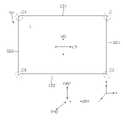
- the display device 100may include a display panel 11 .
- the display panel 11may display an image.
- the display device 100includes a first long side (LS1), a second long side (LS2) opposite to the first long side (LS1), a first long side (LS1), and a second long side (LS2) It may include a first short side (First Short Side, SS1) adjacent to and a second short side (Second Short Side, SS2) opposite to the first short side (SS1).
- first short sideFirst Short Side, SS1
- second short sideSecond Short Side, SS2
- the lengths of the first and second long sides LS1 and LS2are illustrated and described as being longer than the lengths of the first and second short sides SS1 and SS2, but the first and second long sides
- a case in which the lengths of (LS1, LS2) are approximately equal to the lengths of the first and second short sides (SS1, SS2)may also be possible.
- a direction parallel to the long sides LS1 and LS2 of the display device 100may be referred to as a first direction DR1 or a left-right direction LR.
- a direction parallel to the short sides SS1 and SS2 of the display device 1may be referred to as a second direction DR2 or a vertical direction UD.
- a direction perpendicular to the long sides LS1 and LS2 and the short sides SS1 and SS2 of the display device 1may be referred to as a third direction DR3 or a front-back direction FR.
- a direction in which the display panel 11 displays an imagemay be referred to as a front direction, and a direction opposite to this may be referred to as a rear direction.
- the side of the first long side LS1may be referred to as an upper side or an upper surface.
- the second long side LS2may be referred to as the lower side or the lower surface.
- the side of the first short side SS1may be referred to as a left side or a seating surface.
- the second short side SS2 sidemay be referred to as a right side or a right side.
- the first long side LS1 , the second long side LS2 , the first short side SS1 , and the second short side SS2may be referred to as edges of the display device 100 . Also, a point where the first long side LS1 , the second long side LS2 , the first short side SS1 , and the second short side SS2 meet each other may be referred to as a corner.
- a point where the first long side LS1 and the first short side SS1 meetmay be referred to as a first corner C1.
- a point where the first short side SS1 and the second long side LS2 meetmay be referred to as a second corner C2.
- a point where the second long side LS2 and the second short side SS2 meetmay be referred to as a third corner C3.
- a point where the second short side SS2 and the first long side LS1 meetmay be referred to as a fourth corner C4.
- the display panel 11may be an OLED panel.
- the display panel 11may divide an image into a plurality of pixels and output an image by matching color, brightness, and saturation for each pixel.
- the display panel 11may be divided into an active area in which an image is displayed and a de-active area in which an image is not displayed.
- the display panel 11may generate light corresponding to a color of red, green, or blue according to a control signal.
- the display panel 11may be provided with various panels such as LCD.
- the cover 20may move vertically from the front of the display panel 11 .
- the cover 20may cover at least a portion of the front surface of the display panel 11 while moving upward.
- the cover 20may expose the front surface of the display panel 11 to the outside while going down.
- the cover 20may cover at least a portion of the front surface of the display panel 11 while going down. As the cover 20 moves upward, the front surface of the display panel 11 may be exposed to the outside.
- the cover 20may include a metal or fabric material.
- the display device 100may include a frame 110 .
- the frame 110may form a skeleton of the display device 100 .
- the frame 110may include an outer frame 111 , a guide frame 112 , an upper frame 113 , a middle frame 114 , inner frames 115 and 116 , and a lower frame 117 .
- the outer frame 111forms a periphery of the frame 110 and may be formed in the shape of a rectangular frame as a whole.
- the outer frame 111includes the first outer frame 111a forming the upper end of the outer frame 111 , the second outer frame 111b forming the lower end of the outer frame 111 , and the left end of the outer frame 111 . It may include a third outer frame 111c to form, and a fourth outer frame 111d to form a right end of the outer frame 111 .
- the guide frame 112is positioned between the first outer frame 111a and the lower frame 117 and may extend long in the vertical direction.
- the guide frame 112may include a first guide frame 112a adjacent to the third outer frame 111c and a second guide frame 112b adjacent to the fourth outer frame 111d.
- the first guide frame 112amay be spaced apart from the third outer frame 111c to the right by a first interval ga.
- the second guide frame 112bmay be spaced apart from the fourth outer frame 111d to the left by a second interval gb.
- the second interval gbmay be the same as the first interval ga.
- the upper frame 113is positioned between the first guide frame 112a and the second guide frame 112b, and may extend long in the left and right directions.
- the upper frame 113may be coupled to the first guide frame 112a and the second guide frame 112b.
- the middle frame 114is positioned between the first outer frame 111a and the lower frame 117 and may extend long in the vertical direction.
- the middle frame 114may include a first middle frame 114a and a second middle frame 114b coupled to the first outer frame 111a and the lower frame 117 and spaced apart from each other in the left and right directions.
- the inner frames 115 and 116are positioned between the upper frame 113 and the lower frame 117 and may extend long in the left and right directions.
- the inner frames 115 and 116are positioned between the first guide frame 112a and the first middle frame 114a, are coupled to the first guide frame 112a and the first middle frame 114a, and are vertically aligned with each other.
- a pair of spaced apart first inner frames 115a and 115bmay be included.
- the inner frames 115 and 116are positioned between the second guide frame 112b and the second middle frame 114b, are coupled to the second guide frame 112b and the second middle frame 114b, and are vertically aligned with each other.
- a pair of spaced apart second inner frames 116a and 116bmay be included.
- the lower frame 117may be positioned below the upper frame 113 .
- the lower frame 117is positioned between the third outer frame 111c and the fourth outer frame 111d and may extend long in the left and right directions.
- the lower frame 117may be coupled to the third outer frame 111c and the fourth outer frame 111d.
- the display device 100may include a cover assembly 120 .
- the cover assembly 120may include a cover frame 121 and a bracket 122 .
- the cover frame 121forms a periphery of the cover assembly 120 and may be formed in the shape of a rectangular frame as a whole.
- the first frame 121a of the cover frame 121may extend in the left and right directions, and may form an upper end of the cover frame 121 .
- the second frame 121b of the cover frame 121extends in the left and right directions, and may form a lower end of the cover frame 121 .
- the third frame 121c of the cover frame 121extends in the vertical direction and may form a left end of the cover frame 121 .
- the fourth frame 121d of the cover frame 121extends in the vertical direction and may form a right end of the cover frame 121 .
- the bracket 122is positioned between the upper end and the lower end of the cover frame 121 , and may be coupled to the rear surface of the cover frame 121 .
- the bracket 122may be adjacent to the upper end of the cover frame 121 , that is, the first frame 121a.
- the bracket 122may include a first part 1221 , a second part 1222 , and a third part 1223 .
- the first part 1221forms the front surface of the bracket 122 and may be fixed to the rear surface of the cover frame 121 .
- the second part 1222may be bent backward from the first part 1221 to form a side surface of the bracket 122 .
- the third part 1223may be bent left or right from the second part 1222 to face the first part 1221 .
- the third part 1223may be rearwardly spaced apart from the first part 1221 by a first length d1 .
- the bracket 122may include a first bracket 122a coupled to the rear surface of the third frame 121c and a second bracket 122b coupled to the rear surface of the fourth frame 121d. .
- a lower hole 123may be formed while passing through the second frame 121b in the front and rear directions.
- the shape of the lower hole 123may be a shape in which holes having different radii are combined. That is, the lower hole 123 may be divided into a first hole 1231 having a first radius r1 and a second hole 1232 having a second radius r2 .
- the second radius r2is smaller than the first radius r1
- the second hole 1232may be merged with the first hole 1231 under the first hole 1231 .
- the lower hole 123may include a first lower hole 123a, a second lower hole 123b, and a third lower hole 123c spaced apart from each other in the left and right directions.
- the side hole 124may be formed while penetrating the third frame 121c and/or the fourth frame 121d in the front-rear direction.
- the shape of the side hole 124may be a shape in which holes having different radii are combined. That is, the side hole 124 may be divided into a third hole 1241 having a third radius r3 and a fourth hole 1242 having a fourth radius r4 .
- the fourth radius r4is smaller than the third radius r3
- the fourth hole 1242may be merged with the third hole 1241 under the third hole 1241 .
- the side hole 124may include a first side hole 124a formed in the third frame 121c and a second side hole 124b formed in the fourth frame 121d.
- first bracket 122a and the second bracket 122bmay have an upper end having a first height ha and a lower end having a second height hb with respect to the lower end of the second frame 121b.
- the height of the first side hole 124a and the second side hole 124b with respect to the lower end of the second frame 121bmay be smaller than the second height hb.
- the holder 125may include a body 1251 coupled to the rear surface of the first frame 121a.
- the body 1251may be formed of a flat plate as a whole.
- the upper hole 1251amay be formed while passing through the body 1251 in the front-rear direction.
- the shape of the upper hole 1251amay be a combination of a circular hole having a fifth radius r5 and a slit.
- the slitmay be formed to be elongated in the vertical direction at the upper and lower sides of the hole.
- the holder 125may be referred to as a latch.
- the first gap 1251bis spaced apart from the upper hole 1251a to the left, and may be formed in an arc shape having a sixth radius r6.
- a portion 1252 of the body 1251is located between the upper hole 1251a and the first gap 1251b, has elasticity, and is formed as a first gimbal or a first rib.
- the second gap 1251cis spaced apart from the upper hole 1251a to the right, and may be formed in an arc shape having a sixth radius r6.
- a part 1253 of the body 1251is located between the upper hole 1251a and the second gap 1251c, has elasticity, and is formed as a second gimbal or a second rib.
- the fastening part including the above-described upper hole 1251a , the first gap 1251b , and the second gap 1251cmay be provided as a pair of fastening parts spaced apart from each other in the left and right directions.
- the boss 1254may protrude rearward from the rear surface of the body 1251 of the holder 125 and be inserted into the boss hole 121a-1 formed in the first frame 121a.
- the fastening member Srsuch as a screw, may pass through the body 1251 of the holder 125 and be fastened to the fastening hole 121a-2 formed in the first frame 121a.
- the holder 125may be detachably coupled to the first frame 121a.
- the holder 125may include a first holder 125a, a second holder 125b, and a third holder 125c spaced apart from each other in the left and right directions.
- the cover assembly 120may include a plate 126 having a front surface to which the cover 20 (refer to FIG. 2 ) is coupled.
- the plurality of holes 126a, 126b, 126c, 126d, 126e, and 126fmay be formed to pass through the plate 126 in the front-rear direction, and may be spaced apart from each other.
- a lower pin (127, lower pin)may protrude rearward from the rear surface of the plate (126).
- the lower fin 127may be adjacent to the bottom of the plate 126 .
- the lower pin 127includes a lower head 1271 having a certain radius r10, and a lower neck 1272 coupled to the lower head 1271 and the plate 126 between the lower head 1271 and the plate 126. may include In this case, the radius of the lower neck 1272 may be smaller than the radius of the lower head 1271 .
- the lower pin 127may include a first lower pin 127a, a second lower pin 127b, and a third lower pin 127c that are spaced apart from each other in the left and right directions.
- the side pins 128may protrude rearward from the rear surface of the plate 126 .
- the side fin 128may be adjacent to the left end or the right end of the plate 126 .
- the side pin 128is a side head 1281 having a certain radius r20, and a side neck 1282 coupled to the side head 1281 and the plate 126 between the side head 1281 and the plate 126. may include In this case, the radius of the side neck 1282 may be smaller than the radius of the side head 1281 .
- the side fin 128may include a first side fin 128a adjacent to a left end of the plate 126 and a second side fin 128b adjacent to a right end of the plate 126 .
- the upper pin 129may be provided as a pair that protrudes backward from the rear surface of the plate 126 and is spaced apart from each other in the left and right directions.
- the upper fin 129may be adjacent to the top of the plate 126 .
- the upper pin 129includes an upper head 1291 having a certain radius r30, and an upper neck 1292 coupled to the upper head 1291 and the plate 126 between the upper head 1291 and the plate 126. may include In this case, the radius of the upper neck 1292 may be smaller than the radius of the upper head 1291 .
- the upper fin 129may include a first upper fin 129a, a second upper fin 129b, and a third upper fin 129c that are spaced apart from each other in the left and right directions.
- the plate 126may be detachably coupled to the cover frame 121 from the front of the cover frame 121 .
- the radius r10 of the lower head 1271may be smaller than or equal to the first radius r1 (refer to FIG. 5 ) of the first hole 1231 .
- a radius r10 of the lower head 1271may be greater than a second radius r2 of the second hole 1232 (refer to FIG. 5 ). That is, the lower head 1271 may be moved downward after passing through the first hole 1231 by a user or the like and span the rear surface of the second frame 121b forming a boundary of the second hole 1232 .
- the lower end of the plate 126may span the entire surface of the second frame 121b forming the boundary of the second hole 1232 . Accordingly, movement of the lower pin 127 in the front-rear direction may be restricted.
- the radius r20 of the side head 1281may be smaller than or equal to the third radius r3 (refer to FIG. 5 ) of the third hole 1241 . Also, a radius r20 of the side head 1281 may be greater than a fourth radius r4 (refer to FIG. 5 ) of the fourth hole 1242 . That is, the side head 1281 is moved downward after passing through the third hole 1241 by the user, etc. of the third frame 121c or the fourth frame 121d forming the boundary of the fourth hole 1242 . It can be hung on the back.
- the radius (r30, see FIG. 7) of the upper head 1291is larger than the fifth radius (r5, see FIG. 5) of the upper hole 1251a, the sixth of the first gap 1251b or the second gap 1251c It may be smaller than the radius r6 (refer to FIG. 5). That is, the upper head 1291 may be spread over the rear surface of the body 1251 after passing through the upper hole 1251a while spreading the first gimbal 1252 and the second gimbal 1253 left and right by a user or the like.
- the above-described coupling of the plate 126 and the cover frame 121is the coupling of the lower pin 127 and the lower hole 123, the coupling of the side pin 128 and the side hole 124, and the upper in chronological order. It may be formed by a combination of the pin 129 and the upper hole 1251a.
- the combination of the upper pin 129 and the upper hole 1251ais to move the upper head 1291 to the upper hole 1251a in a state in which the plate 126 is tilted forward with respect to the body 1251 of the holder 125 . It can be done by inserting.
- the upper end 1211 of the first frame 121amay protrude forward by a predetermined distance 110 from the first frame 121a.
- the upper end of the plate 126may be positioned below the upper end 1211 of the first frame 121a by a predetermined interval g10 .
- the end of the cover 20passes between the upper end of the plate 126 and the upper end 1211 of the first frame 121a, and between the plate 126 and the first frame 121a. can be fixed.
- the upper end 1261 of the plate 126may protrude rearward from the plate 126 by a predetermined length 120 .
- the upper end of the first frame 121amay be positioned below the upper end 1261 of the plate 126 by a predetermined interval g20 .
- the cover 20(refer to FIG. 2 ) may be attached to the front surface of the plate 126 .
- an adhesivesuch as a double-sided tape may be provided between the cover 20 and the plate 126 .
- the display unit 10may include a display panel 11 and a frame 13 .
- the frame 13may be coupled to the display panel 11 from the rear of the display panel 11 .
- the frame 13may have electronic components electrically connected to the display panel 11 mounted thereon.
- the frame 13may be referred to as a main frame, an inner frame, or a module cover.
- the front surface of the display unit 10may be spaced rearward from the plate 126 . Accordingly, the cover 20 (refer to FIG. 2 ) coupled to the front surface of the plate 126 may cover at least a portion of the front surface of the display panel 11 .
- the display unit 10may be installed in a space defined by the first outer frame 111a, the first guide frame 112a, the upper frame 113, and the second guide frame 112b.
- the upper frame 113may be coupled to the display unit 10 from the lower side of the display unit 10 to support the load of the display unit 10 .
- the total height of the display panel 11may be h1.
- the cover assembly 120When the cover assembly 120 is positioned below the display unit 10 , the entire front surface of the display panel 11 may be exposed forward.
- the lift assembly 130may be installed on the lower frame 117 .
- FIG. 14is an enlarged view of region M of FIG. 13 .
- the lift assembly 130may include a first lift assembly 130a positioned on a relatively left side and a second lift assembly 130b positioned on a relatively right side.
- first lift assembly 130apositioned on a relatively left side
- second lift assembly 130bpositioned on a relatively right side.
- descriptionwill be made based on the second lift assembly 130b, and the description thereof may also be applied to the first lift assembly 130a.
- the lift assembly 130may include a motor 131 , a gearbox 135 having a plurality of gears embedded therein, a pinion 135e , and a rack 136 .
- the gearbox 135may be installed on the lower frame 117 .
- the motor 131may provide rotational force.
- the motor 131may be an electric motor capable of adjusting a rotation direction and a rotation speed.
- the motor 131may be installed on the motor mount 132 .
- the motor 131may be located above the gearbox 135 .
- the rotation shaft 131a of the motor 131extends in the vertical direction, and a part thereof may be inserted into the gearbox 135 .
- the encoder 134may be installed on one side of the motor 131 to control the rotation of the motor 131 .
- the gearbox 135may include a first gear 135a, a second gear 135b, a worm 135c, and a worm wheel 135d.
- the first gear 135amay be fixed to the rotation shaft 131a of the motor 131 and rotate together with the rotation shaft 131a.
- the second gear 135bmay be engaged with the first gear 135a and may be fixed to the first shaft 131b.
- the first shaft 131bmay be spaced apart from the rotation shaft 131a and extend in the vertical direction.
- the worm 135cmay be spaced apart from the second gear 135b and fixed to the first shaft 131b.
- the worm wheel 135dmay be engaged with the worm 135c and fixed to the second shaft 131c.
- the second shaft 131cmay be spaced apart from the rotation shaft 131a and the first shaft 131b and extend in the left and right directions. Accordingly, the power of the motor 131 is transmitted from the first gear 135a fixed to the rotation shaft 131a to the second shaft 131c via the second gear 135b, the worm 135c, and the worm wheel 135d. can be transmitted.
- the pinion 135emay be fixed to the second shaft 131c and rotate together with the second shaft 131c.
- the rack 136may be engaged with the pinion 135e and extend long in the vertical direction. That is, when the pinion 135e rotates, the rack 136 may move in the vertical direction.
- the rack 136may be coupled to the third part 1223 of the bracket 122 .
- a fastening membersuch as a screw may penetrate the hole 1224 formed in the third part 1223 to be fastened to the rack 136 .
- the cover assembly 120(refer to FIG. 8 ) including the bracket 122 may move in the vertical direction.
- the cover 20(refer to FIG. 2) is located in front of the display unit 10, but the lift assembly 130 and the bracket 122 coupled thereto are located at the rear of the display unit 10, so that the display panel ( 11) and the gap between the cover 20 can be minimized.
- the pad 133may be adjacent to the motor 131 and be fixed to the guide frame 112 .
- the bosses 1121a , 1121b , and 1121cmay protrude rearward from the rear surface of the guide frame 112 , and may be coupled to the pad 133 .
- the pad 133may include a first pad 133a, a second pad 133b, and a third pad 133c spaced apart from each other in the vertical direction.
- the first boss 1121ais inserted into the first pad 133a
- the second boss 1121bis inserted into the second pad 133b
- the third boss 1121cis inserted into the third pad 133c.
- the pad 133may have a side surface in which a groove is formed.
- the flange 132amay protrude from the side surface of the mount 132 and be inserted into the groove of the pad 133 .
- the pad 133may be fitted into the bosses 1121a , 1121b , and 1121c of the guide frame 112 and the flange 132a of the mount 132 .
- the pad 133may include an elastic material such as rubber or silicone.
- the pad 133may reduce noise or vibration generated during driving of the motor 131 .
- the cover assembly 120may cover a portion of the front surface of the display panel 11 .
- an area corresponding to the second height h2 from the lower end of the display panel 11 to the upper side of the front surface of the display panel 11may be covered by the cover assembly 120 .
- a region corresponding to a third height h3 from the top of the display panel 11 to the bottom of the front surface of the display panel 11may be exposed forward.
- the sum of the second height h2 and the third height h3is equal to the total height h1 of the display panel 11 .
- FIG. 20is an enlarged view of area N of FIG. 19 .
- the rack 136 and the bracket 122 coupled theretomay be moved upward along the guide frame 112 .
- the rack 136 and the bracket 122 coupled theretofollow the guide frame 112 . can be moved down.
- the movement distance of the bracket 122can be adjusted by controlling the rotation of the motor 131 .
- the motor 131may be a step motor.
- the movement of the bracket 122may be the same as the movement of the cover assembly 120 including the bracket 122 .
- the rail 118is installed on the guide frame 112 and may be positioned between the first part 1221 and the third part 1223 of the bracket 122 .
- the rail 118may extend long in the vertical direction to guide the movement of the bracket 122 .
- the rail 118may include a first flange 1181 , a web 1182 , and a second flange 1183 .
- the first flange 1181may form the rear surface of the rail 118
- the second flange 1183may be fixed to the rear surface of the guide frame 112 while forming the front surface of the rail 118 .
- Web 1182may be coupled to first flange 1181 and second flange 1183 between first and second flanges 1181 and 1183 .
- the first flange 1181 and the second flange 1183may have the same width
- the web 1182may have a width smaller than the width of the first flange 1181 .
- the rail 118may be formed in an overall H-beam or I-beam shape.
- the guide 1224is fixed to the front surface of the third part 1223 , and is coupled to the rail 118 to slide along the rail 118 .
- the guide 1224surrounds the first flange 1181 at the front of the rail 118 , and may have an end adjacent to the web 1182 . That is, the guide 1224 may move vertically along the rail 118 while being coupled to the first flange 1181 .
- the protective materials 1225 and 1226are disposed on the first flange 1181 and the guide 1224, the rail 118 and / or the guide 1224 according to the movement of the guide 1224 with respect to the rail 118. damage can be prevented.
- materials of the protective materials 1225 and 1226may be different from those of the rail 118 and the guide 1224 .
- the pinion 135emay engage the rack 136 at the front of the rack 136 .
- the body (unsigned) of the rack 136is formed with a gear engaged with the pinion 135e, and may include a depression 1362 that is formed while being depressed toward the pinion 135e from the body.
- the supporter 137may be inserted into the depression 1362 .
- the supporter 137may be formed of a material different from that of the body.
- the bodymay include a plastic material, and the supporter 137 may include a metal material such as aluminum (Al). Accordingly, the supporter 137 may improve torsional rigidity and/or bending rigidity of the rack 136 .
- the base 138may be fixed to the side of the gearbox 135 .
- Pulleys (138a, 138b, pulley)may be rotatably coupled to the base (138).
- the rotation shaft Z1 of the pulleys 138a and 138bmay be parallel to the front-rear direction.
- the pulleys 138a and 138bmay include a first pulley 138a and a second pulley 138b that are spaced apart from each other in the vertical direction.
- the rib 1361protrudes from the side surface of the rack 136 adjacent to the pulleys 138a and 138b, and may be vertically movably fitted to the pulleys 138a and 138b.
- the pulleys 138a and 138bmay include a first part 138a-1, a second part 138a-2, and a third part 138a-3.
- the first part 138a - 1may contact the side surface of the rib 1361 between the second part 138a - 2 and the third part 138a - 3 .
- the second part 138a - 2may contact the rear surface of the rib 1361 .
- the third part 138a - 3may contact the front surface of the rib 1361 .
- the gap gd between the second part 138a - 2 and the third part 138a - 3may be equal to or greater than the thickness of the rib 1361 . Accordingly, the pulleys 138a and 138b may limit the forward and backward flow and/or leftward flow while guiding the vertical movement of the rib 1361 and the rack 136 coupled thereto.
- the roller 139may contact the side opposite to the side of the rack 136 adjacent to the pulleys 138a and 138b.
- the roller 139may be rotatably coupled to the protrusion 1111 protruding from the inner surface of the fourth outer frame 111d toward the pinion 135e.
- the rotation shaft Z2 of the roller 139may be parallel to the front-rear direction. Accordingly, the roller 139 may restrict the right flow of the rack 136 .
- the front frame 111hmay be bent from the front end of the fourth outer frame 111d and be inclined at an acute angle with respect to the fourth outer frame 111d. Meanwhile, the fourth outer frame 111d forms a right side surface of the frame 111 and may be referred to as a side frame.
- the rear frame 111fmay be coupled to the rear end of the fourth outer frame 111d and the rear end of the front frame 111h.
- the rear frame 111fmay be located at the rear of the rack 136 .
- a fastening membersuch as a screw may penetrate the hole F of the rear frame 111f and be fastened to the rear end of the front frame 111h.
- the front frame 111h and the rear frame 111fmay extend in the vertical direction, and the lower portion of the lower frame 117 may be longer than the upper portion of the lower frame 117 .
- the fourth outer frame 111d, the front frame 111h, and the rear frame 111fmay partition an internal space in which the rack 136 is movable.
- the third outer frame 111cmay also include a front frame 111h and a rear frame 111f, which will be described above and below.
- the first protrusion 1112may protrude from the inner surface of the fourth outer frame 111d toward the rack 136 .
- the first protrusion 1112may be in line contact with the rack 136 .
- a portion of the first protrusion 1112 in contact with the rack 136may be formed to be curved or provided as an edge.
- the second protrusion 1113may protrude from the inner surface of the front frame 111h toward the rib 1361 .
- the second protrusion 1113may be in line contact with the rib 1361 .
- a portion of the second protrusion 1113 in contact with the rib 1361may be formed to be curved or provided as an edge.
- the third protrusions 1362 and 1363may protrude rearward from the rear surface of the rack 136 and may be in line contact with the rear frame 111f.
- a portion of the third protrusions 1362 and 1363 in contact with the rear frame 111fmay be formed to be curved or provided as an edge.
- the first protrusion 1112restricts the right flow of the rack 136
- the second protrusion 1113restricts the front flow of the rack 136
- the rear frame 111f of the rack 136Backflow can be restricted.
- the contact between the first protrusion 1112 and the rack 136 , the contact between the second protrusion 1113 and the rib 1361 , and the contact between the third protrusion 1362 and 1363 and the rear frame 111fare line contact. As it is formed, resistance due to contact between members is minimized, so that vertical movement of the rack 136 can be made smoothly.
- a display panela frame on which the display panel is installed; a cover assembly having a cover positioned in front of the display panel and movably coupled to the frame; and a lift assembly installed on the frame and configured to move the cover assembly
- the lift assemblyincludes: a motor providing a rotational force; a pinion connected to the rotation shaft of the motor; and a rack engaged with the pinion and extending in a movement direction of the cover assembly, wherein the cover assembly provides a display device including: a bracket coupled to the rack at the rear of the display panel.
- the lift assemblymay further include: a pair of lift assemblies spaced apart from each other in the left and right directions.
- the cover assemblyfurther includes: a plate coupled to the cover at a rear side of the cover, and the bracket includes: a first part coupled to the plate at a rear side of the plate ; a second part bent backward from the first part; And, it further includes a third part that is bent from the second part to the left or right to face the first part, wherein the third part is located at the rear of the display panel, and may be coupled to the rack.
- the framefurther includes a rail installed on the frame, positioned between the first part and the third part, and extending in the moving direction of the cover assembly, wherein the bracket comprises: : A guide fixed to the front surface of the third part and coupled to the rail may further include a guide movable along the rail.
- the rackincludes: a body in which a gear engaged with the pinion is formed; a body having a depression formed while being depressed toward the pinion from the body; In addition, it may further include a supporter inserted into the depression and formed of a material different from that of the body.
- the rackis adjacent to the side surface of the rack, further comprising a pulley rotatable about an axis parallel to the front-rear direction, wherein the rack is: protruding from the side of the rack adjacent to the pulley , It may further include a rib fitted to the pulley movably in the vertical direction.
- the pulleymay include: a first part contacting a side surface of the rib; a second part contacting the rear surface of the rib; And, it further includes a third part in contact with the front surface of the rib, the distance between the second part and the third part may be equal to or greater than the thickness of the rib.
- itmay further include a roller that is in contact with a side opposite to the side of the rack adjacent to the pulley, and rotatable about an axis parallel to the front-rear direction.
- the frameincludes: a side frame forming a side surface of the frame; a front frame that is bent from a front end of the side frame and is inclined at an acute angle with respect to the side frame; And, it further includes a rear frame coupled to the rear end of the side frame and the rear end of the front frame, wherein the side frame, the front frame, and the rear frame may partition an inner space in which the rack is movable.
- the side framefurther includes: a first protrusion protruding from an inner surface of the side frame toward the rack, the outer surface of the first protrusion being capable of line contact with the rack can
- the front framefurther includes: a second protrusion protruding from an inner surface of the front frame toward the rib, the outer surface of the second protrusion being capable of line contact with the rib can
- the rear frameis located at the rear of the rack, and the rack further includes: a third protrusion protruding rearward from the rear surface of the rack and capable of line contact with the rear frame.
- the lift assemblyfurther includes a pad adjacent to the motor and having a grooved side surface, the lift assembly comprising: a mount on which the motor is mounted; And, it protrudes from the mount and further includes a flange inserted into the groove, the frame may further include: a guide frame having a boss coupled to the pad.
- the lift assemblyfurther includes: a gear box accommodating a plurality of gears connected to the rotation shaft of the motor and the pinion, wherein the frame: extends in a left and right direction; It may further include a lower frame in which the gear box is installed.
- the covermay gradually cover the front surface of the display panel while ascending, or may gradually expose the front surface of the display panel to the outside while descending.
- configuration A described in a specific embodiment and/or drawingsmay be combined with configuration B described in other embodiments and/or drawings. That is, even if the combination between the configurations is not directly described, it means that the combination is possible except for the case where it is explained that the combination is impossible (For example, a configuration "A” described in one embodiment of the disclosure and the drawings. and a configuration "B" described in another embodiment of the disclosure and the drawings may be combined with each other. Namely, although the combination between the configurations is not directly described, the combination is possible except in the case where it is described that the combination is impossible).
Landscapes
- Engineering & Computer Science (AREA)
- General Engineering & Computer Science (AREA)
- Power Engineering (AREA)
- Mechanical Engineering (AREA)
- Physics & Mathematics (AREA)
- General Physics & Mathematics (AREA)
- Theoretical Computer Science (AREA)
- Microelectronics & Electronic Packaging (AREA)
- Optics & Photonics (AREA)
- Chemical & Material Sciences (AREA)
- Crystallography & Structural Chemistry (AREA)
- Devices For Indicating Variable Information By Combining Individual Elements (AREA)
Abstract
Description
Translated fromKorean본 개시는 디스플레이 디바이스에 관한 것이다.The present disclosure relates to a display device.
정보화 사회가 발전함에 따라 디스플레이 디바이스에 대한 요구도 다양한 형태로 증가하고 있으며, 이에 부응하여 근래에는 LCD(Liquid Crystal Display Device), PDP(Plasma Display Panel), ELD(Electro luminescent Display), VFD(Vacuum Fluorescent Display), OLED(Organic Light Emitting Diode) 등 다양한 디스플레이 디바이스가 연구되어 사용되고 있다.As the information society develops, the demand for display devices is also increasing in various forms. Various display devices such as display) and OLED (Organic Light Emitting Diode) have been researched and used.
이 중에서, LCD 패널은 액정층을 사이에 두고 서로 대향하는 TFT 기판과 컬러 기판을 구비하며, 백라이트 유닛으로부터 제공되는 빛을 이용해 화상을 표시할 수 있다. 그리고, OLED 패널은 투명전극이 형성된 기판에 자체적으로 발광할 수 있는 유기물층을 증착하여 화상을 표시할 수 있다.Among them, the LCD panel includes a TFT substrate and a color substrate that face each other with a liquid crystal layer interposed therebetween, and can display an image using light provided from a backlight unit. In addition, the OLED panel can display an image by depositing an organic material layer capable of emitting light by itself on the substrate on which the transparent electrode is formed.
최근 디스플레이 패널의 전면을 커버하는 구조에 대한 많은 연구가 이루어지고 있다.Recently, many studies have been made on a structure for covering the front surface of a display panel.
본 개시는 전술한 문제 및 다른 문제를 해결하는 것을 목적으로 한다.SUMMARY OF THE INVENTION The present disclosure aims to solve the above and other problems.
또 다른 목적은 디스플레이 패널의 전면을 덮거나 개방할 수 있는 디스플레이 디바이스를 제공하는 것일 수 있다.Another object may be to provide a display device capable of covering or opening the front surface of the display panel.
또 다른 목적은 디스플레이 패널과 커버 사이의 간격을 최소화할 수 있는 디스플레이 디바이스를 제공하는 것일 수 있다.Another object may be to provide a display device capable of minimizing the gap between the display panel and the cover.
또 다른 목적은 디스플레이 패널의 전면을 덮는 커버를 안정적으로 상승시키거나 하강시킬 수 있는 메커니즘을 제공하는 것일 수 있다.Another object may be to provide a mechanism capable of stably raising or lowering a cover covering the front surface of the display panel.
또 다른 목적은 커버가 상승하거나 하강하는 동안에 커버가 전후 및/또는 좌우로 유동되는 것을 방지할 수 있는 구조를 제공하는 것일 수 있다.Another object may be to provide a structure that can prevent the cover from flowing back and forth and/or left and right while the cover is raised or lowered.
상술한 목적을 달성하기 위한 본 개시의 일 측면에 따르면, 디스플레이 패널; 상기 디스플레이 패널이 설치되는 프레임; 상기 디스플레이 패널의 전방에 위치하는 커버를 구비하고, 상기 프레임에 이동 가능하게 결합되는 커버 어셈블리; 그리고, 상기 프레임에 설치되고, 상기 커버 어셈블리를 이동시키는 리프트 어셈블리를 포함하고, 상기 리프트 어셈블리는: 회전력을 제공하는 모터; 상기 모터의 회전축에 연결되는 피니언; 그리고, 상기 피니언에 맞물리고, 상기 커버 어셈블리의 이동방향으로 연장되는 랙을 포함하고, 상기 커버 어셈블리는: 상기 디스플레이 패널의 후방에서 상기 랙에 결합되는 브라켓을 포함하는 디스플레이 디바이스를 제공한다.According to an aspect of the present disclosure for achieving the above object, the display panel; a frame on which the display panel is installed; a cover assembly having a cover positioned in front of the display panel and movably coupled to the frame; and a lift assembly installed on the frame and configured to move the cover assembly, wherein the lift assembly includes: a motor providing a rotational force; a pinion connected to the rotation shaft of the motor; and a rack engaged with the pinion and extending in a movement direction of the cover assembly, wherein the cover assembly provides a display device including: a bracket coupled to the rack at the rear of the display panel.
본 개시에 따른 디스플레이 디바이스의 효과에 대하여 설명하면 다음과 같다.The effect of the display device according to the present disclosure will be described as follows.
본 개시의 실시 예들 중 적어도 하나에 의하면, 디스플레이 패널의 전면을 덮거나 개방할 수 있는 디스플레이 디바이스를 제공할 수 있다.According to at least one of the embodiments of the present disclosure, it is possible to provide a display device capable of covering or opening the front surface of the display panel.
본 개시의 실시 예들 중 적어도 하나에 의하면, 디스플레이 패널과 커버 사이의 간격을 최소화할 수 있는 디스플레이 디바이스를 제공할 수 있다.According to at least one of the embodiments of the present disclosure, it is possible to provide a display device capable of minimizing the gap between the display panel and the cover.
본 개시의 실시 예들 중 적어도 하나에 의하면, 디스플레이 패널의 전면을 덮는 커버를 안정적으로 상승시키거나 하강시킬 수 있는 메커니즘을 제공할 수 있다.According to at least one of the embodiments of the present disclosure, a mechanism for stably raising or lowering the cover covering the front surface of the display panel may be provided.
본 개시의 실시 예들 중 적어도 하나에 의하면, 커버가 상승하거나 하강하는 동안에 커버가 전후 및/또는 좌우로 유동되는 것을 방지할 수 있는 구조를 제공할 수 있다.According to at least one of the embodiments of the present disclosure, a structure capable of preventing the cover from flowing back and forth and/or left and right while the cover is raised or lowered may be provided.
본 개시의 적용 가능성의 추가적인 범위는 이하의 상세한 설명으로부터 명백해질 것이다. 그러나 본 개시의 사상 및 범위 내에서 다양한 변경 및 수정은 당업자에게 명확하게 이해될 수 있으므로, 상세한 설명 및 본 개시의 바람직한 실시 예와 같은 특정 실시 예는 단지 예시로 주어진 것으로 이해되어야 한다.Further scope of applicability of the present disclosure will become apparent from the following detailed description. However, it should be understood that the detailed description and specific embodiments such as preferred embodiments of the present disclosure are given by way of example only, since various changes and modifications within the spirit and scope of the present disclosure may be clearly understood by those skilled in the art.
도 1 내지 25는 본 개시의 실시 예들에 따른 디스플레이 디바이스의 예들을 도시한 도면들이다.1 to 25 are diagrams illustrating examples of display devices according to embodiments of the present disclosure.
이하, 첨부된 도면을 참조하여 본 명세서에 개시된 실시 예를 상세히 설명하되, 도면 부호에 관계없이 동일하거나 유사한 구성요소는 동일한 참조 번호를 부여하고 이에 대한 중복되는 설명은 생략하기로 한다.Hereinafter, the embodiments disclosed in the present specification will be described in detail with reference to the accompanying drawings, but the same or similar components are assigned the same reference numbers regardless of reference numerals, and redundant description thereof will be omitted.
이하의 설명에서 사용되는 구성요소에 대한 접미사 "모듈" 및 "부"는 명세서 작성의 용이함만이 고려되어 부여되거나 혼용되는 것으로서, 그 자체로 서로 구별되는 의미 또는 역할을 갖는 것은 아니다.The suffixes "module" and "part" for the components used in the following description are given or mixed in consideration of only the ease of writing the specification, and do not have distinct meanings or roles by themselves.
또한, 본 명세서에 개시된 실시 예를 설명함에 있어서 관련된 공지 기술에 대한 구체적인 설명이 본 명세서에 개시된 실시 예의 요지를 흐릴 수 있다고 판단되는 경우 그 상세한 설명을 생략한다. 또한, 첨부된 도면은 본 명세서에 개시된 실시 예를 쉽게 이해할 수 있도록 하기 위한 것일 뿐, 첨부된 도면에 의해 본 명세서에 개시된 기술적 사상이 제한되지 않으며, 본 개시의 사상 및 기술 범위에 포함되는 모든 변경, 균등물 내지 대체물을 포함하는 것으로 이해되어야 한다.In addition, in describing the embodiments disclosed in the present specification, if it is determined that detailed descriptions of related known technologies may obscure the gist of the embodiments disclosed in the present specification, the detailed description thereof will be omitted. In addition, the accompanying drawings are only for easy understanding of the embodiments disclosed in the present specification, and the technical spirit disclosed in the present specification is not limited by the accompanying drawings, and all changes included in the spirit and scope of the present disclosure , should be understood to include equivalents or substitutes.
제1, 제2 등과 같이 서수를 포함하는 용어는 다양한 구성요소들을 설명하는데 사용될 수 있지만, 상기 구성요소들은 상기 용어들에 의해 한정되지는 않는다. 상기 용어들은 하나의 구성요소를 다른 구성요소로부터 구별하는 목적으로만 사용된다.Terms including an ordinal number such as 1st, 2nd, etc. may be used to describe various elements, but the elements are not limited by the terms. The above terms are used only for the purpose of distinguishing one component from another.
어떤 구성요소가 다른 구성요소에 "연결되어" 있다거나 "접속되어" 있다고 언급된 때에는, 그 다른 구성요소에 직접적으로 연결되어 있거나 또는 접속되어 있을 수도 있지만, 중간에 다른 구성요소가 존재할 수도 있다고 이해되어야 할 것이다. 반면에, 어떤 구성요소가 다른 구성요소에 "직접 연결되어" 있다거나 "직접 접속되어" 있다고 언급된 때에는, 중간에 다른 구성요소가 존재하지 않는 것으로 이해되어야 할 것이다.When a component is referred to as being “connected” or “connected” to another component, it may be directly connected or connected to the other component, but it is understood that other components may exist in between. it should be On the other hand, when it is mentioned that a certain element is "directly connected" or "directly connected" to another element, it should be understood that no other element is present in the middle.
단수의 표현은 문맥상 명백하게 다르게 뜻하지 않는 한, 복수의 표현을 포함한다.The singular expression includes the plural expression unless the context clearly dictates otherwise.
이하의 설명에서, 특정 도면을 참조하여 실시 예를 설명하더라도, 필요한 경우, 상기 특정 도면에 나타나지 않은 참조 번호를 언급할 수 있으며, 상기 특정 도면에 나타나지 않은 참조 번호는, 다른 도면에(in the other figures) 상기 참조 번호가 나타난 경우에 사용한다.In the following description, even if the embodiment is described with reference to specific drawings, if necessary, reference numbers not appearing in the specific drawings may be referred to, and reference numbers not appearing in the specific drawings are in the other drawings (in the other drawings). figures) are used where the above reference numbers appear.
도 1을 참조하면, 디스플레이 디바이스(100)는 디스플레이 패널(11)을 포함할 수 있다. 디스플레이 패널(11)은 화상을 표시할 수 있다.Referring to FIG. 1 , the
디스플레이 디바이스(100)는 제1 장변(First Long Side, LS1), 제1 장변(LS1)에 대향하는 제2 장변(Second Long Side, LS2), 제1 장변(LS1) 및 제2 장변(LS2)에 인접하는 제1 단변(First Short Side, SS1) 및 제1 단변(SS1)에 대향하는 제2 단변(Second Short Side, SS2)을 포함할 수 있다. 한편, 설명의 편의를 위해 제1 및 제2 장변(LS1, LS2)의 길이가 제1 및 제2 단변(SS1, SS2)의 길이보다 더 긴 것으로 도시하고 설명하고 있으나, 제1 및 제2 장변(LS1, LS2)의 길이가 제1 및 제2 단변(SS1, SS2)의 길이와 대략 동일한 경우도 가능할 수 있다.The
디스플레이 디바이스(100)의 장변(Long Side, LS1, LS2)과 나란한 방향을 제1 방향(DR1) 또는 좌우방향(LR)이라고 할 수 있다. 디스플레이 디바이스(1)의 단변(Short Side, SS1, SS2)과 나란한 방향을 제2 방향(DR2) 또는 상하방향(UD)이라고 할 수 있다. 디스플레이 디바이스(1)의 장변(LS1, LS2) 및 단변(SS1, SS2)에 수직한 방향을 제3 방향(DR3) 또는 전후방향(FR)이라고 할 수 있다. 여기서, 디스플레이 패널(11)이 화상을 표시하는 방향을 전방이라고 하고, 이와 반대되는 방향을 후방이라고 할 수 있다.A direction parallel to the long sides LS1 and LS2 of the
제1 장변(LS1) 쪽을 상측 또는 상면이라 할 수 있다. 제2 장변(LS2) 쪽을 하측 또는 하면이라 할 수 있다. 제1 단변(SS1) 쪽을 좌측 또는 좌면이라 할 수 있다. 제2 단변(SS2) 쪽을 우측 또는 우면이라 할 수 있다.The side of the first long side LS1 may be referred to as an upper side or an upper surface. The second long side LS2 may be referred to as the lower side or the lower surface. The side of the first short side SS1 may be referred to as a left side or a seating surface. The second short side SS2 side may be referred to as a right side or a right side.
제1 장변(LS1), 제2 장변(LS2), 제1 단변(SS1), 그리고 제2 단변(SS2)은 디스플레이 디바이스(100)의 엣지(edge)라 칭할 수 있다. 또한, 제1 장변(LS1), 제2 장변(LS2), 제1 단변(SS1), 그리고 제2 단변(SS2)이 서로 만나는 지점을 코너(corner)라 칭할 수 있다.The first long side LS1 , the second long side LS2 , the first short side SS1 , and the second short side SS2 may be referred to as edges of the
예를 들면, 제1 장변(LS1)과 제1 단변(SS1)이 만나는 지점은 제1 코너(C1)라 칭할 수 있다. 제1 단변(SS1)과 제2 장변(LS2)이 만나는 지점은 제2 코너(C2)라 칭할 수 있다. 제2 장변(LS2)과 제2 단변(SS2)이 만나는 지점은 제3 코너(C3)라 칭할 수 있다. 제2 단변(SS2)과 제1 장변(LS1)이 만나는 지점은 제4 코너(C4)라 칭할 수 있다.For example, a point where the first long side LS1 and the first short side SS1 meet may be referred to as a first corner C1. A point where the first short side SS1 and the second long side LS2 meet may be referred to as a second corner C2. A point where the second long side LS2 and the second short side SS2 meet may be referred to as a third corner C3. A point where the second short side SS2 and the first long side LS1 meet may be referred to as a fourth corner C4.
예를 들면, 디스플레이 패널(11)은 OLED 패널일 수 있다. 디스플레이 패널(11)은 화상을 복수개의 픽셀들로 나누어 각 픽셀당 색상, 명도, 채도를 맞추어 화상을 출력할 수 있다. 디스플레이 패널(11)은 화상이 표시되는 활성 영역(active area)과, 화상이 표시되지 않는 비활성 영역(de-active area)으로 구분될 수 있다. 디스플레이 패널(11)은 제어신호에 따라 레드, 그린, 또는 블루의 색에 해당하는 빛을 발생시킬 수 있다. 한편, 디스플레이 패널(11)은 LCD 등 다양한 패널로 구비되는 것이 가능하다.For example, the
도 1 및 2를 참조하면, 커버(20)는 디스플레이 패널(11)의 전방에서 상하방향으로 이동할 수 있다.1 and 2 , the
예를 들면, 커버(20)는 위로 올라가면서 디스플레이 패널(11)의 전면의 적어도 일부를 덮을 수 있다. 커버(20)는 아래로 내려가면서 디스플레이 패널(11)의 전면을 외부로 노출시킬 수 있다.For example, the
다른 예를 들면, 커버(20)는 아래로 내려가면서 디스플레이 패널(11)의 전면의 적어도 일부를 덮을 수 있다. 커버(20)는 위로 올라가면서 디스플레이 패널(11)의 전면을 외부로 노출시킬 수 있다.As another example, the
한편, 커버(20)는 메탈 또는 패브릭 재질을 포함할 수 있다.Meanwhile, the
도 3을 참조하면, 디스플레이 디바이스(100)는 프레임(110)을 포함할 수 있다. 프레임(110)은 디스플레이 디바이스(100)의 골격을 형성할 수 있다. 프레임(110)은 아우터 프레임(111), 가이드 프레임(112), 어퍼 프레임(113), 미들 프레임(114), 이너 프레임(115, 116), 그리고 로어 프레임(117)을 포함할 수 있다.Referring to FIG. 3 , the
아우터 프레임(111)은 프레임(110)의 둘레를 형성하며, 전체적으로 사각 프레임의 형상으로 형성될 수 있다. 아우터 프레임(111)은 아우터 프레임(111)의 상단을 형성하는 제1 아우터 프레임(111a), 아우터 프레임(111)의 하단을 형성하는 제2 아우터 프레임(111b), 아우터 프레임(111)의 좌단을 형성하는 제3 아우터 프레임(111c), 그리고 아우터 프레임(111)의 우단을 형성하는 제4 아우터 프레임(111d)을 포함할 수 있다.The
가이드 프레임(112)은 제1 아우터 프레임(111a)과 로어 프레임(117) 사이에 위치하고, 상하방향으로 길게 연장될 수 있다. 가이드 프레임(112)은 제3 아우터 프레임(111c)에 인접하는 제1 가이드 프레임(112a)과 제4 아우터 프레임(111d)에 인접하는 제2 가이드 프레임(112b)을 포함할 수 있다. 제1 가이드 프레임(112a)은 제3 아우터 프레임(111c)으로부터 제1 간격(ga)만큼 우측으로 이격될 수 있다. 제2 가이드 프레임(112b)은 제4 아우터 프레임(111d)으로부터 제2 간격(gb)만큼 좌측으로 이격될 수 있다. 예를 들면, 제2 간격(gb)은 제1 간격(ga)과 동일할 수 있다.The
어퍼 프레임(113)은 제1 가이드 프레임(112a)과 제2 가이드 프레임(112b) 사이에 위치하고, 좌우방향으로 길게 연장될 수 있다. 어퍼 프레임(113)은 제1 가이드 프레임(112a)과 제2 가이드 프레임(112b)에 결합될 수 있다.The
미들 프레임(114)은 제1 아우터 프레임(111a)과 로어 프레임(117) 사이에 위치하고, 상하방향으로 길게 연장될 수 있다. 미들 프레임(114)은 제1 아우터 프레임(111a)과 로어 프레임(117)에 결합되고, 좌우방향으로 서로 이격되는 제1 미들 프레임(114a)과 제2 미들 프레임(114b)을 포함할 수 있다.The
이너 프레임(115, 116)은 어퍼 프레임(113)과 로어 프레임(117) 사이에 위치하고, 좌우방향으로 길게 연장될 수 있다. 이너 프레임(115, 116)은 제1 가이드 프레임(112a)과 제1 미들 프레임(114a) 사이에 위치하고, 제1 가이드 프레임(112a)과 제1 미들 프레임(114a)에 결합되며, 상하방향으로 서로 이격되는 한쌍의 제1 이너 프레임(115a, 115b)을 포함할 수 있다. 이너 프레임(115, 116)은 제2 가이드 프레임(112b)과 제2 미들 프레임(114b) 사이에 위치하고, 제2 가이드 프레임(112b)과 제2 미들 프레임(114b)에 결합되며, 상하방향으로 서로 이격되는 한쌍의 제2 이너 프레임(116a, 116b)을 포함할 수 있다.The
로어 프레임(117)은 어퍼 프레임(113)의 하측에 위치할 수 있다. 로어 프레임(117)은 제3 아우터 프레임(111c)과 제4 아우터 프레임(111d) 사이에 위치하고, 좌우방향으로 길게 연장될 수 있다. 로어 프레임(117)은 제3 아우터 프레임(111c)과 제4 아우터 프레임(111d)에 결합될 수 있다.The
도 4를 참조하면, 디스플레이 디바이스(100)는 커버 어셈블리(120)를 포함할 수 있다. 커버 어셈블리(120)는 커버 프레임(121)과 브라켓(122)을 포함할 수 있다.Referring to FIG. 4 , the
커버 프레임(121)은 커버 어셈블리(120)의 둘레를 형성하며, 전체적으로 사각 프레임의 형상으로 형성될 수 있다. 커버 프레임(121)의 제1 프레임(121a)은 좌우방향으로 연장되며, 커버 프레임(121)의 상단을 형성할 수 있다. 커버 프레임(121)의 제2 프레임(121b)은 좌우방향으로 연장되며, 커버 프레임(121)의 하단을 형성할 수 있다. 커버 프레임(121)의 제3 프레임(121c)은 상하방향으로 연장되며, 커버 프레임(121)의 좌단을 형성할 수 있다. 커버 프레임(121)의 제4 프레임(121d)은 상하방향으로 연장되며, 커버 프레임(121)의 우단을 형성할 수 있다.The
브라켓(122)은 커버 프레임(121)의 상단과 하단 사이에 위치하고, 커버 프레임(121)의 후면에 결합될 수 있다. 브라켓(122)은 커버 프레임(121)의 상단, 즉 제1 프레임(121a)에 인접할 수 있다. 브라켓(122)은 제1 파트(1221), 제2 파트(1222), 그리고 제3 파트(1223)를 포함할 수 있다.The
제1 파트(1221)는 브라켓(122)의 전면을 형성하며, 커버 프레임(121)의 후면에 고정될 수 있다. 제2 파트(1222)는 제1 파트(1221)로부터 후방으로 밴딩되어, 브라켓(122)의 측면을 형성할 수 있다. 제3 파트(1223)는 제2 파트(1222)로부터 좌측 또는 우측으로 밴딩되어 제1 파트(1221)와 마주할 수 있다. 제3 파트(1223)는 제1 파트(1221)로부터 제1 길이(d1)만큼 후방으로 이격될 수 있다.The
예를 들면, 브라켓(122)은 제3 프레임(121c)의 후면에 결합되는 제1 브라켓(122a)과, 제4 프레임(121d)의 후면에 결합되는 제2 브라켓(122b)을 포함할 수 있다.For example, the
도 5 및 6을 참조하면, 로어 홀(123, lower hole)은 제2 프레임(121b)을 전후방향으로 관통하며 형성될 수 있다. 로어 홀(123)의 형상은 서로 다른 반경을 가지는 홀들이 합쳐진 형상일 수 있다. 즉, 로어 홀(123)은 제1 반경(r1)을 가지는 제1 홀(1231)과, 제2 반경(r2)을 가지는 제2 홀(1232)로 구분될 수 있다. 여기서, 제2 반경(r2)은 제1 반경(r1)보다 작으며, 제2 홀(1232)은 제1 홀(1231)의 하측에서 제1 홀(1231)에 합쳐질 수 있다. 예를 들면, 로어 홀(123)은 좌우방향으로 서로 이격되는 제1 로어 홀(123a), 제2 로어 홀(123b), 그리고 제3 로어 홀(123c)을 포함할 수 있다.5 and 6 , a
사이드 홀(124, side hole)은 제3 프레임(121c) 및/또는 제4 프레임(121d)을 전후방향으로 관통하며 형성될 수 있다. 사이드 홀(124)의 형상은 서로 다른 반경을 가지는 홀들이 합쳐진 형상일 수 있다. 즉, 사이드 홀(124)은 제3 반경(r3)을 가지는 제3 홀(1241)과, 제4 반경(r4)을 가지는 제4 홀(1242)로 구분될 수 있다. 여기서, 제4 반경(r4)은 제3 반경(r3)보다 작으며, 제4 홀(1242)은 제3 홀(1241)의 하측에서 제3 홀(1241)에 합쳐질 수 있다. 예를 들면, 사이드 홀(124)은 제3 프레임(121c)에 형성되는 제1 사이드 홀(124a)과, 제4 프레임(121d)에 형성되는 제2 사이드 홀(124b)을 포함할 수 있다.The
한편, 제1 브라켓(122a)과 제2 브라켓(122b)은 제2 프레임(121b)의 하단에 대해 제1 높이(ha)를 가지는 상단과, 제2 높이(hb)를 가지는 하단을 가질 수 있다. 이 경우, 제2 프레임(121b)의 하단에 대한 제1 사이드 홀(124a)과 제2 사이드 홀(124b)의 높이는 제2 높이(hb)보다 작을 수 있다.Meanwhile, the
홀더(125)는 제1 프레임(121a)의 후면에 결합되는 바디(1251)를 포함할 수 있다. 바디(1251)는 전체적으로 평평한 플레이트로 형성될 수 있다. 어퍼 홀(1251a, upper hole)은 바디(1251)를 전후방향으로 관통하며 형성될 수 있다. 어퍼 홀(1251a)의 형상은 제5 반경(r5)을 가지는 원형의 홀(circular hole)과 슬릿이 합쳐진 형상일 수 있다. 여기서, 상기 슬릿은 상기 홀의 상측과 하측에서 상하방향으로 길게 형성될 수 있다. 한편, 홀더(125)는 래치라 칭할 수 있다.The
제1 갭(1251b)은 어퍼 홀(1251a)로부터 좌측으로 이격되며, 제6 반경(r6)을 가지는 호(arc) 형상으로 형성될 수 있다. 이때, 바디(1251)의 일부(1252)는 어퍼 홀(1251a)과 제1 갭(1251b) 사이에 위치하고, 탄성을 가지며, 제1 짐벌(a first gimbal) 또는 제1 리브(a first rib)로 칭할 수 있다. 제2 갭(1251c)은 어퍼 홀(1251a)로부터 우측으로 이격되며, 제6 반경(r6)을 가지는 호(arc) 형상으로 형성될 수 있다. 이때, 바디(1251)의 일부(1253)는 어퍼 홀(1251a)과 제2 갭(1251c) 사이에 위치하고, 탄성을 가지며, 제2 짐벌(a second gimbal) 또는 제2 리브(a second rib)로 칭할 수 있다. 예를 들면, 전술한 어퍼 홀(1251a), 제1 갭(1251b), 및 제2 갭(1251c)을 구비하는 체결부는 좌우방향으로 서로 이격되는 한쌍의 체결부로 구비될 수 있다.The
한편, 보스(1254, boss)는 홀더(125)의 바디(1251)의 후면으로부터 후방으로 돌출되어, 제1 프레임(121a)에 형성된 보스 홀(121a-1)에 삽입될 수 있다. 그리고, 스크류와 같은 체결부재(Sr)는 홀더(125)의 바디(1251)를 관통하여, 제1 프레임(121a)에 형성된 체결 홀(121a-2)에 체결될 수 있다. 이로써, 홀더(125)는 제1 프레임(121a)에 분리 가능하게 결합될 수 있다. 예를 들면, 홀더(125)는 좌우방향으로 서로 이격되는 제1 홀더(125a), 제2 홀더(125b), 그리고 제3 홀더(125c)를 포함할 수 있다.Meanwhile, the
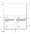
도 7을 참조하면, 커버 어셈블리(120)는 커버(20, 도 2 참조)가 결합되는 전면을 가지는 플레이트(126)를 포함할 수 있다. 예를 들면, 복수개의 홀들(126a, 126b, 126c, 126d, 126e, 126f)은 플레이트(126)를 전후방향으로 관통하여 형성되고, 서로 이격될 수 있다.Referring to FIG. 7 , the
로어 핀(127, lower pin)은 플레이트(126)의 후면으로부터 후방으로 돌출될 수 있다. 로어 핀(127)은 플레이트(126)의 하단에 인접할 수 있다. 로어 핀(127)은 일정 반경(r10)을 가지는 로어 헤드(1271)와, 로어 헤드(1271)와 플레이트(126) 사이에서 로어 헤드(1271)와 플레이트(126)에 결합되는 로어 넥(1272)을 포함할 수 있다. 이때, 로어 넥(1272)의 반경은 로어 헤드(1271)의 반경보다 작을 수 있다. 예를 들면, 로어 핀(127)은 좌우방향으로 서로 이격되는 제1 로어 핀(127a), 제2 로어 핀(127b), 그리고 제3 로어 핀(127c)을 포함할 수 있다.A lower pin (127, lower pin) may protrude rearward from the rear surface of the plate (126). The
사이드 핀(128, side pin)은 플레이트(126)의 후면으로부터 후방으로 돌출될 수 있다. 사이드 핀(128)은 플레이트(126)의 좌단 또는 우단에 인접할 수 있다. 사이드 핀(128)은 일정 반경(r20)을 가지는 사이드 헤드(1281)와, 사이드 헤드(1281)와 플레이트(126) 사이에서 사이드 헤드(1281)와 플레이트(126)에 결합되는 사이드 넥(1282)을 포함할 수 있다. 이때, 사이드 넥(1282)의 반경은 사이드 헤드(1281)의 반경보다 작을 수 있다. 예를 들면, 사이드 핀(128)은 플레이트(126)의 좌단에 인접하는 제1 사이드 핀(128a)과, 플레이트(126)의 우단에 인접하는 제2 사이드 핀(128b)을 포함할 수 있다.The side pins 128 may protrude rearward from the rear surface of the
어퍼 핀(129)은 플레이트(126)의 후면으로부 후방으로 돌출되고, 좌우방향으로 서로 이격되는 한쌍으로 구비될 수 있다. 어퍼 핀(129)은 플레이트(126)의 상단에 인접할 수 있다. 어퍼 핀(129)은 일정 반경(r30)을 가지는 어퍼 헤드(1291)와, 어퍼 헤드(1291)와 플레이트(126) 사이에서 어퍼 헤드(1291)와 플레이트(126)에 결합되는 어퍼 넥(1292)을 포함할 수 있다. 이때, 어퍼 넥(1292)의 반경은 어퍼 헤드(1291)의 반경보다 작을 수 있다. 예를 들면, 어퍼 핀(129)은 좌우방향으로 서로 이격되는 제1 어퍼 핀(129a), 제2 어퍼 핀(129b), 그리고 제3 어퍼 핀(129c)을 포함할 수 있다.The
도 8 및 9를 참조하면, 플레이트(126)는 커버 프레임(121)의 전방에서 커버 프레임(121)에 분리 가능하게 결합될 수 있다.8 and 9 , the
로어 헤드(1271)의 반경(r10, 도 7 참조)은 제1 홀(1231)의 제1 반경(r1, 도 5 참조)보다 작거나 이와 같을 수 있다. 그리고, 로어 헤드(1271)의 반경(r10)은 제2 홀(1232)의 제2 반경(r2, 도 5 참조)보다 클 수 있다. 즉, 로어 헤드(1271)는 사용자 등에 의해 제1 홀(1231)을 통과한 후 아래로 이동되어 제2 홀(1232)의 경계를 형성하는 제2 프레임(121b)의 후면에 걸쳐질 수 있다. 그리고, 플레이트(126)의 하단은 제2 홀(1232)의 경계를 형성하는 제2 프레임(121b)의 전면에 걸쳐질 수 있다. 이로써, 전후방향에서 로어 핀(127)의 이동이 제한될 수 있다.The radius r10 of the lower head 1271 (refer to FIG. 7 ) may be smaller than or equal to the first radius r1 (refer to FIG. 5 ) of the
사이드 헤드(1281)의 반경(r20, 도 7 참조)은 제3 홀(1241)의 제3 반경(r3, 도 5 참조)보다 작거나 이와 같을 수 있다. 그리고, 사이드 헤드(1281)의 반경(r20)은 제4 홀(1242)의 제4 반경(r4, 도 5 참조)보다 클 수 있다. 즉, 사이드 헤드(1281)는 사용자 등에 의해 제3 홀(1241)을 통과한 후 아래로 이동되어 제4 홀(1242)의 경계를 형성하는 제3 프레임(121c) 또는 제4 프레임(121d)의 후면에 걸쳐질 수 있다.The radius r20 of the side head 1281 (refer to FIG. 7 ) may be smaller than or equal to the third radius r3 (refer to FIG. 5 ) of the
어퍼 헤드(1291)의 반경(r30, 도 7 참조)은 어퍼 홀(1251a)의 제5 반경(r5, 도 5 참조)보다 크되, 제1 갭(1251b) 또는 제2 갭(1251c)의 제6 반경(r6, 도 5 참조)보다 작을 수 있다. 즉, 어퍼 헤드(1291)는 사용자 등에 의해 제1 짐벌(1252)과 제2 짐벌(1253)을 좌우로 벌리면서 어퍼 홀(1251a)을 통과한 후 바디(1251)의 후면에 걸쳐질 수 있다.The radius (r30, see FIG. 7) of the
한편, 전술한 플레이트(126)와 커버 프레임(121)의 결합은 시간 순서대로 로어 핀(127)과 로어 홀(123)의 결합, 사이드 핀(128)과 사이드 홀(124)의 결합, 그리고 어퍼 핀(129)과 어퍼 홀(1251a)의 결합으로 이루어질 수 있다. 이 경우, 어퍼 핀(129)과 어퍼 홀(1251a)의 결합은 플레이트(126)를 홀더(125)의 바디(1251)에 대해 전방으로 젖힌 상태에서 어퍼 헤드(1291)를 어퍼 홀(1251a)에 끼우는 방식으로 이루어질 수 있다.On the other hand, the above-described coupling of the
도 10을 참조하면, 제1 프레임(121a)의 상단(1211)은 제1 프레임(121a)으로부터 전방으로 일정 거리(l10)만큼 돌출될 수 있다. 이 경우, 플레이트(126)의 상단은 일정 간격(g10)만큼 제1 프레임(121a)의 상단(1211)의 하측에 위치할 수 있다.Referring to FIG. 10 , the
예를 들면, 커버(20, 도 2 참조)의 말단은 플레이트(126)의 상단과 제1 프레임(121a)의 상단(1211) 사이를 거쳐, 플레이트(126)와 제1 프레임(121a) 사이에 고정될 수 있다.For example, the end of the cover 20 (refer to FIG. 2 ) passes between the upper end of the
도 11을 참조하면, 플레이트(126)의 상단(1261)은 플레이트(126)로부터 후방으로 일정 길이(l20)만큼 돌출될 수 있다. 이 경우, 제1 프레임(121a)의 상단은 일정 간격(g20)만큼 플레이트(126)의 상단(1261)의 하측에 위치할 수 있다.Referring to FIG. 11 , the
예를 들면, 커버(20, 도 2 참조)는 플레이트(126)의 전면에 부착될 수 있다. 이를 위해, 커버(20)와 플레이트(126) 사이에 양면 테이프 등의 접착재가 구비될 수 있다.For example, the cover 20 (refer to FIG. 2 ) may be attached to the front surface of the
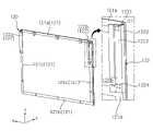
도 12 및 13을 참조하면, 디스플레이부(10)는 디스플레이 패널(11)과 프레임(13)을 포함할 수 있다. 여기서, 프레임(13)은 디스플레이 패널(11)의 후방에서 디스플레이 패널(11)에 결합될 수 있다. 예를 들면, 프레임(13)은 디스플레이 패널(11)과 전기적으로 연결되는 전자 부품들이 실장될 수 있다. 한편, 프레임(13)은 메인프레임, 이너프레임, 또는 모듈커버로 칭할 수 있다.12 and 13 , the
디스플레이부(10)의 전면은 플레이트(126)로부터 후방으로 이격될 수 있다. 이로써, 플레이트(126)의 전면에 결합된 커버(20, 도 2 참조)는 디스플레이 패널(11)의 전면의 적어도 일부를 덮을 수 있다.The front surface of the
디스플레이부(10)는 제1 아우터 프레임(111a), 제1 가이드 프레임(112a), 어퍼 프레임(113), 그리고 제2 가이드 프레임(112b)에 의해 구획되는 공간에 설치될 수 있다. 이때, 어퍼 프레임(113)은 디스플레이부(10)의 하측에서 디스플레이부(10)에 결합되어, 디스플레이부(10)의 하중을 지지할 수 있다. 그리고, 디스플레이 패널(11)의 전체 높이는 h1일 수 있다.The
커버 어셈블리(120)가 디스플레이부(10)의 하측에 위치하면, 디스플레이 패널(11)의 전면 전부가 전방으로 노출될 수 있다.When the
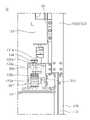
도 13 내지 15를 참조하면, 리프트 어셈블리(130)는 로어 프레임(117) 상에 설치될 수 있다. 여기서, 도 14는 도 13의 M 영역을 확대한 도면이다. 예를 들면, 리프트 어셈블리(130)는 상대적으로 좌측에 위치하는 제1 리프트 어셈블리(130a)와, 상대적으로 우측에 위치하는 제2 리프트 어셈블리(130b)를 포함할 수 있다. 이하, 간략한 설명을 위하여 제2 리프트 어셈블리(130b)를 기준으로 설명하며, 이에 대한 설명은 제1 리프트 어셈블리(130a)에도 마찬가지로 적용될 수 있다.13 to 15 , the
리프트 어셈블리(130)는 모터(131), 복수개의 기어들이 내장된 기어박스(135), 피니언(135e), 그리고 랙(136)을 포함할 수 있다. 이때, 기어박스(135)는 로어 프레임(117) 상에 설치될 수 있다.The
모터(131)는 회전력을 제공할 수 있다. 예를 들면, 모터(131)는 회전방향과 회전속도를 조절할 수 있는 전기모터일 수 있다. 모터(131)는 모터 마운트(132) 상에 설치될 수 있다. 예를 들면, 모터(131)는 기어박스(135)의 상측에 위치할 수 있다. 모터(131)의 회전축(131a)은 상하방향으로 연장되고, 일부가 기어박스(135) 내로 삽입될 수 있다. 한편, 엔코더(134)는 모터(131)의 일측에 설치되어 모터(131)의 회전을 조절할 수 있다.The
기어박스(135)는 제1 기어(135a), 제2 기어(135b), 웜(135c, worm), 그리고 웜휠(135d, worm wheel)을 포함할 수 있다. 제1 기어(135a)는 모터(131)의 회전축(131a)에 고정되어, 회전축(131a)과 함께 회전될 수 있다. 제2 기어(135b)는 제1 기어(135a)에 맞물리고, 제1 축(131b)에 고정될 수 있다. 여기서, 제1 축(131b)은 회전축(131a)으로부터 이격되고, 상하방향으로 연장될 수 있다. 웜(135c)은 제2 기어(135b)로부터 이격되고, 제1 축(131b)에 고정될 수 있다. 웜휠(135d)은 웜(135c)에 맞물리고, 제2 축(131c)에 고정될 수 있다. 여기서, 제2 축(131c)은 회전축(131a) 및 제1 축(131b)으로부터 이격되고, 좌우방향으로 연장될 수 있다. 이에 따라, 모터(131)의 동력은 회전축(131a)에 고정된 제1 기어(135a)로부터 제2 기어(135b), 웜(135c), 그리고 웜휠(135d)을 거쳐 제2 축(131c)으로 전달될 수 있다.The
피니언(135e)은 제2 축(131c)에 고정되어, 제2 축(131c)과 함께 회전될 수 있다. 랙(136)은 피니언(135e)과 맞물리고, 상하방향으로 길게 연장될 수 있다. 즉, 피니언(135e)이 회전하면, 랙(136)은 상하방향으로 이동할 수 있다.The
한편, 랙(136)은 브라켓(122)의 제3 파트(1223)에 결합될 수 있다. 예를 들면, 스크류와 같은 체결부재(미도시)가 제3 파트(1223)에 형성된 홀(1224)을 관통하여 랙(136)에 체결될 수 있다.Meanwhile, the
이에 따라, 모터(131)가 구동되면, 브라켓(122)을 구비하는 커버 어셈블리(120, 도 8 참조)는 상하방향으로 이동할 수 있다. 그리고, 커버(20, 도 2 참조)는 디스플레이부(10)의 전방에 위치하되, 리프트 어셈블리(130) 및 이에 결합되는 브라켓(122)은 디스플레이부(10)의 후방에 위치하여, 디스플레이 패널(11)과 커버(20) 사이의 간격을 최소화할 수 있다.Accordingly, when the
도 16 및 17을 참조하면, 패드(133)는 모터(131)에 인접하고, 가이드 프레임(112)에 고정될 수 있다. 보스(1121a, 1121b, 1121c)는 가이드 프레임(112)의 후면으로부터 후방으로 돌출되어, 패드(133)에 결합될 수 있다. 예를 들면, 패드(133)는 상하방향으로 서로 이격되는 제1 패드(133a), 제2 패드(133b), 그리고 제3 패드(133c)를 포함할 수 있다. 이때, 제1 보스(1121a)는 제1 패드(133a)에 삽입되고, 제2 보스(1121b)는 제2 패드(133b)에 삽입되며, 제3 보스(1121c)는 제3 패드(133c)에 삽입될 수 있다. 그리고, 패드(133)는 그루브가 형성된 측면을 가질 수 있다.16 and 17 , the
이 경우, 플랜지(132a)는 마운트(132)의 측면으로부터 돌출되어, 패드(133)의 상기 그루브에 삽입될 수 있다. 다시 말해, 패드(133)는 가이드 프레임(112)의 보스(1121a, 1121b, 1121c)와, 마운트(132)의 플랜지(132a)에 끼워질 수 있다. 그리고, 패드(133)는 고무 또는 실리콘과 같은 탄성재질을 포함할 수 있다.In this case, the
이에 따라, 패드(133)는 모터(131)의 구동 중에 발생되는 소음 또는 진동을 줄일 수 있다.Accordingly, the
도 18 및 19를 참조하면, 커버 어셈블리(120)는 디스플레이 패널(11)의 전면의 일부를 덮을 수 있다. 예를 들면, 디스플레이 패널(11)의 전면 중에 디스플레이 패널(11)의 하단으로부터 상측으로 제2 높이(h2)만큼에 해당하는 영역은 커버 어셈블리(120)에 의해 덮여질 수 있다. 예를 들면, 디스플레이 패널(11)의 전면 중에 디스플레이 패널(11)의 상단으로부터 하측으로 제3 높이(h3)만큼에 해당하는 영역은 전방으로 노출될 수 있다. 이때, 제2 높이(h2)와 제3 높이(h3)의 합은 디스플레이 패널(11)의 전체 높이(h1)와 같다.18 and 19 , the
도 19 내지 21을 참조하면, 브라켓(122)은 랙(136)과 함께 위로 이동되어, 로어 프레임(117)으로부터 멀어질 수 있다. 여기서, 도 20은 도 19의 N 영역을 확대한 도면이다.19 to 21 , the
전술한 모터(131)가 구동되어 피니언(135e)이 제1 회전방향으로 회전되면, 랙(136)과 이에 결합된 브라켓(122)은 가이드 프레임(112)을 따라서 위로 이동될 수 있다. 전술한 모터(131)가 구동되어 피니언(135e)이 상기 제1 회전방향에 반대되는 제2 회전방향으로 회전되면, 랙(136)과 이에 결합된 브라켓(122)은 가이드 프레임(112)을 따라서 아래로 이동될 수 있다. 이때, 모터(131)의 회전을 제어하여 브라켓(122)의 이동 거리를 조절할 수 있다. 예를 들면, 모터(131)는 스텝 모터일 수 있다.When the above-described
한편, 브라켓(122)의 이동은 브라켓(122)을 구비하는 커버 어셈블리(120)의 이동과 같을 수 있다.Meanwhile, the movement of the
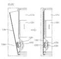
도 17 및 22를 참조하면, 레일(118)은 가이드 프레임(112)에 설치되고, 브라켓(122)의 제1 파트(1221)와 제3 파트(1223) 사이에 위치할 수 있다. 레일(118)은 상하방향으로 길게 연장되어, 브라켓(122)의 이동을 가이드할 수 있다.17 and 22 , the
레일(118)은 제1 플랜지(1181), 웹(1182, web), 그리고 제2 플랜지(1183)를 포함할 수 있다. 제1 플랜지(1181)는 레일(118)의 후면을 형성하고, 제2 플랜지(1183)는 레일(118)의 전면을 형성면서 가이드 프레임(112)의 후면에 고정될 수 있다. 웹(1182)은 제1 플랜지(1181)와 제2 플랜지(1183) 사이에서 제1 플랜지(1181)와 제2 플랜지(1183)에 결합될 수 있다. 예를 들면, 제1 플랜지(1181)와 제2 플랜지(1183)는 동일한 폭을 가지며, 웹(1182)은 제1 플랜지(1181)의 폭보다 작은 폭을 가질 수 있다. 레일(118)은 전체적으로 H 형강(H beam) 또는 I 형강(I beam) 형상으로 형성될 수 있다.The
가이드(1224)는 제3 파트(1223)의 전면에 고정되고, 레일(118)에 결합되어 레일(118)을 따라서 슬라이드 이동할 수 있다. 구체적으로, 가이드(1224)는 레일(118)의 전방에서 제1 플랜지(1181)를 둘러싸고, 웹(1182)에 이웃하는 말단을 가질 수 있다. 즉, 가이드(1224)는 제1 플랜지(1181)에 결합된 채로 레일(118)을 따라서 상하방향으로 이동할 수 있다. 한편, 보호재(1225, 1226)는 제1 플랜지(1181)와 가이드(1224)에 배치되어, 레일(118)에 대한 가이드(1224)의 움직임에 따른 레일(118) 및/또는 가이드(1224)의 손상을 방지할 수 있다. 예를 들면, 보호재(1225, 1226)의 재질은 레일(118)과 가이드(1224)의 재질과 다를 수 있다.The
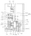
도 21 및 23을 참조하면, 피니언(135e)은 랙(136)의 전방에서 랙(136)에 맞물릴 수 있다. 랙(136)의 바디(미부호)는 피니언(135e)에 맞물리는 기어가 형성되고, 상기 바디로부터 피니언(135e)을 향해 함몰되면서 형성되는 함몰부(1362)를 구비할 수 있다.21 and 23 , the
이 경우, 서포터(137)는 함몰부(1362)에 삽입될 수 있다. 예를 들면, 서포터(137)는 상기 바디와 다른 재질로 형성될 수 있다. 예를 들면, 상기 바디는 플라스틱 재질을 포함하고, 서포터(137)는 알루미늄(Al)과 같은 금속 재질을 포함할 수 있다. 이에 따라, 서포터(137)는 랙(136)의 비틀림 강성 및/또는 굽힘 강성을 향상시킬 수 있다.In this case, the
한편, 베이스(138)는 기어박스(135)의 측면에 고정될 수 있다. 풀리(138a, 138b, pulley)는 베이스(138)에 회전 가능하게 결합될 수 있다. 풀리(138a, 138b)의 회전축(Z1)은 전후방향에 나란할 수 있다. 예를 들면, 풀리(138a, 138b)는 상하방향으로 서로 이격되는 제1 풀리(138a)와 제2 풀리(138b)를 포함할 수 있다. 이 경우, 리브(1361)는 풀리(138a, 138b)에 인접한 랙(136)의 측면으로부터 돌출되어, 풀리(138a, 138b)에 상하방향으로 이동 가능하게 끼워질 수 있다.Meanwhile, the
그리고, 풀리(138a, 138b)의 제1 파트(138a-1), 제2 파트(138a-2), 그리고 제3 파트(138a-3)를 포함할 수 있다. 제1 파트(138a-1)는 제2 파트(138a-2)와 제3 파트(138a-3) 사이에서 리브(1361)의 측면에 접촉할 수 있다. 제2 파트(138a-2)는 리브(1361)의 후면에 접촉할 수 있다. 제3 파트(138a-3)는 리브(1361)의 전면에 접촉할 수 있다. 이 경우, 제2 파트(138a-2)와 제3 파트(138a-3) 사이의 간격(gd)은 리브(1361)의 두께와 동일하거나 이보다 클 수 있다. 이에 따라, 풀리(138a, 138b)는 리브(1361) 및 이에 결합된 랙(136)의 상하 이동을 가이드하면서, 전후 유동 및/또는 좌측 유동을 제한할 수 있다.The
한편, 롤러(139)는 풀리(138a, 138b)에 인접한 랙(136)의 측면에 반대되는 측면에 접촉할 수 있다. 롤러(139)는 제4 아우터 프레임(111d)의 내면으로부터 피니언(135e)을 향해 돌출된 돌출부(1111)에 회전 가능하게 결합될 수 있다. 롤러(139)의 회전축(Z2)은 전후방향에 나란할 수 있다. 이에 따라, 롤러(139)는 랙(136)의 우측 유동을 제한할 수 있다.On the other hand, the
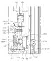
도 24 및 25를 참조하면, 프론트 프레임(111h)은 제4 아우터 프레임(111d)의 전단으로부터 밴딩되고, 제4 아우터 프레임(111d)에 대해 예각을 이루며 경사지게 배치될 수 있다. 한편, 제4 아우터 프레임(111d)은 프레임(111)의 우측면을 형성하며, 사이드 프레임으로 칭할 수 있다. 리어 프레임(111f)은 제4 아우터 프레임(111d)의 후단과 프론트 프레임(111h)의 후단에 결합될 수 있다. 리어 프레임(111f)은 랙(136)의 후방에 위치할 수 있다. 예를 들면, 스크류와 같은 체결 부재는 리어 프레임(111f)의 홀(F)을 관통하여 프론트 프레임(111h)의 후단에 체결될 수 있다. 예를 들면, 프론트 프레임(111h)과 리어 프레임(111f)은 상하방향으로 연장되고, 로어 프레임(117)의 상측에 위치하는 부분보다 하측에 위치하는 부분이 더 길 수 있다.24 and 25 , the
이 경우, 제4 아우터 프레임(111d), 프론트 프레임(111h), 그리고 리어 프레임(111f)은 랙(136)이 이동 가능한 내부 공간을 구획할 수 있다. 한편, 제3 아우터 프레임(111c)에도 상기 및 후술하는 프론트 프레임(111h)과 리어 프레임(111f)이 구비될 수 있다.In this case, the fourth
제1 돌출부(1112)는 제4 아우터 프레임(111d)의 내면으로부터 랙(136)을 향해 돌출될 수 있다. 제1 돌출부(1112)는 랙(136)에 선 접촉할 수 있다. 예를 들면, 제1 돌출부(1112)의 일부로서 랙(136)에 접촉하는 부분은 곡률지게 형성되거나, 엣지로 구비될 수 있다.The
제2 돌출부(1113)는 프론트 프레임(111h)의 내면으로부터 리브(1361)를 향해 돌출될 수 있다. 제2 돌출부(1113)는 리브(1361)에 선 접촉할 수 있다. 예를 들면, 제2 돌출부(1113)의 일부로서 리브(1361)에 접촉하는 부분은 곡률지게 형성되거나, 엣지로 구비될 수 있다.The
제3 돌출부(1362, 1363)는 랙(136)의 후면으로부터 후방으로 돌출되어, 리어 프레임(111f)에 선 접촉할 수 있다. 예를 들면, 제3 돌출부(1362, 1363)의 일부로서 리어 프레임(111f)에 접촉하는 부분은 곡률지게 형성되거나, 엣지로 구비될 수 있다.The
이에 따라, 제1 돌출부(1112)는 랙(136)의 우측 유동을 제한하고, 제2 돌출부(1113)는 랙(136)의 전방 유동을 제한하며, 리어 프레임(111f)은 랙(136)의 후방 유동을 제한할 수 있다. 그리고, 제1 돌출부(1112)와 랙(136)의 접촉, 제2 돌출부(1113)와 리브(1361)의 접촉, 및 제3 돌출부(1362, 1363)와 리어 프레임(111f)의 접촉이 선 접촉으로 형성됨에 따라, 부재들 간의 접촉에 의한 저항이 최소화되어 랙(136)의 상하 이동이 원활하게 이루어질 수 있다.Accordingly, the
본 개시의 일 측면에 따르면, 디스플레이 패널; 상기 디스플레이 패널이 설치되는 프레임; 상기 디스플레이 패널의 전방에 위치하는 커버를 구비하고, 상기 프레임에 이동 가능하게 결합되는 커버 어셈블리; 그리고, 상기 프레임에 설치되고, 상기 커버 어셈블리를 이동시키는 리프트 어셈블리를 포함하고, 상기 리프트 어셈블리는: 회전력을 제공하는 모터; 상기 모터의 회전축에 연결되는 피니언; 그리고, 상기 피니언에 맞물리고, 상기 커버 어셈블리의 이동방향으로 연장되는 랙을 포함하고, 상기 커버 어셈블리는: 상기 디스플레이 패널의 후방에서 상기 랙에 결합되는 브라켓을 포함하는 디스플레이 디바이스를 제공한다.According to an aspect of the present disclosure, a display panel; a frame on which the display panel is installed; a cover assembly having a cover positioned in front of the display panel and movably coupled to the frame; and a lift assembly installed on the frame and configured to move the cover assembly, wherein the lift assembly includes: a motor providing a rotational force; a pinion connected to the rotation shaft of the motor; and a rack engaged with the pinion and extending in a movement direction of the cover assembly, wherein the cover assembly provides a display device including: a bracket coupled to the rack at the rear of the display panel.
또 본 개시의 다른(another) 측면에 따르면, 상기 리프트 어셈블리는: 좌우방향으로 서로 이격되는 한쌍의 리프트 어셈블리를 더 포함할 수 있다.According to another aspect of the present disclosure, the lift assembly may further include: a pair of lift assemblies spaced apart from each other in the left and right directions.
또 본 개시의 다른(another) 측면에 따르면, 상기 커버 어셈블리는: 상기 커버의 후방에서 상기 커버에 결합되는 플레이트를 더 포함하고, 상기 브라켓은: 상기 플레이트의 후방에서 상기 플레이트에 결합되는 제1 파트; 상기 제1 파트로부터 후방으로 밴딩되는 제2 파트; 그리고, 상기 제2 파트로부터 좌측 또는 우측으로 밴딩되어 상기 제1 파트와 마주하는 제3 파트를 더 포함하고, 상기 제3 파트는, 상기 디스플레이 패널의 후방에 위치하고, 상기 랙에 결합될 수 있다.According to another aspect of the present disclosure, the cover assembly further includes: a plate coupled to the cover at a rear side of the cover, and the bracket includes: a first part coupled to the plate at a rear side of the plate ; a second part bent backward from the first part; And, it further includes a third part that is bent from the second part to the left or right to face the first part, wherein the third part is located at the rear of the display panel, and may be coupled to the rack.
또 본 개시의 다른(another) 측면에 따르면, 상기 프레임에 설치되고, 상기 제1 파트와 상기 제3 파트 사이에 위치하며, 상기 커버 어셈블리의 이동방향으로 연장되는 레일을 더 포함하고, 상기 브라켓은: 상기 제3 파트의 전면에 고정되고, 상기 레일에 결합되어 상기 레일을 따라서 이동 가능한 가이드를 더 포함할 수 있다.According to another aspect of the present disclosure, the frame further includes a rail installed on the frame, positioned between the first part and the third part, and extending in the moving direction of the cover assembly, wherein the bracket comprises: : A guide fixed to the front surface of the third part and coupled to the rail may further include a guide movable along the rail.
또 본 개시의 다른(another) 측면에 따르면, 상기 랙은: 상기 피니언에 맞물리는 기어가 형성되는 바디;로서, 상기 바디로부터 상기 피니언을 향해 함몰되면서 형성되는 함몰부를 구비하는 바디; 그리고, 상기 함몰부에 삽입되고, 상기 바디와 다른 재질로 형성되는 서포터를 더 포함할 수 있다.According to another (another) aspect of the present disclosure, the rack includes: a body in which a gear engaged with the pinion is formed; a body having a depression formed while being depressed toward the pinion from the body; In addition, it may further include a supporter inserted into the depression and formed of a material different from that of the body.
또 본 개시의 다른(another) 측면에 따르면, 상기 랙의 측면에 인접하고, 전후방향에 나란한 축을 중심으로 회전 가능한 풀리를 더 포함하고, 상기 랙은: 상기 풀리에 인접한 상기 랙의 측면로부터 돌출되어, 상기 풀리에 상하방향으로 이동 가능하게 끼워지는 리브를 더 포함할 수 있다.According to another aspect of the present disclosure, it is adjacent to the side surface of the rack, further comprising a pulley rotatable about an axis parallel to the front-rear direction, wherein the rack is: protruding from the side of the rack adjacent to the pulley , It may further include a rib fitted to the pulley movably in the vertical direction.
또 본 개시의 다른(another) 측면에 따르면, 상기 풀리는: 상기 리브의 측면에 접촉하는 제1 파트; 상기 리브의 후면에 접촉하는 제2 파트; 그리고, 상기 리브의 전면에 접촉하는 제3 파트를 더 포함하고, 상기 제2 파트와 상기 제3 파트 사이의 간격은 상기 리브의 두께와 동일하거나 이보다 클 수 있다.According to another aspect of the present disclosure, the pulley may include: a first part contacting a side surface of the rib; a second part contacting the rear surface of the rib; And, it further includes a third part in contact with the front surface of the rib, the distance between the second part and the third part may be equal to or greater than the thickness of the rib.
또 본 개시의 다른(another) 측면에 따르면, 상기 풀리에 인접한 상기 랙의 측면에 반대되는 측면에 접촉하고, 전후방향에 나란한 축을 중심으로 회전 가능한 롤러를 더 포함할 수 있다.In addition, according to another (another) aspect of the present disclosure, it may further include a roller that is in contact with a side opposite to the side of the rack adjacent to the pulley, and rotatable about an axis parallel to the front-rear direction.
또 본 개시의 다른(another) 측면에 따르면, 상기 프레임은: 상기 프레임의 측면을 형성하는 사이드 프레임; 상기 사이드 프레임의 전단으로부터 밴딩되고, 상기 사이드 프레임에 대해 예각을 이루며 경사지게 배치되는 프론트 프레임; 그리고, 상기 사이드 프레임의 후단과 상기 프론트 프레임의 후단에 결합되는 리어 프레임을 더 포함하고, 상기 사이드 프레임, 상기 프론트 프레임, 그리고 상기 리어 프레임은, 상기 랙이 이동 가능한 내부 공간을 구획할 수 있다.According to another aspect of the present disclosure, the frame includes: a side frame forming a side surface of the frame; a front frame that is bent from a front end of the side frame and is inclined at an acute angle with respect to the side frame; And, it further includes a rear frame coupled to the rear end of the side frame and the rear end of the front frame, wherein the side frame, the front frame, and the rear frame may partition an inner space in which the rack is movable.
또 본 개시의 다른(another) 측면에 따르면, 상기 사이드 프레임은: 상기 사이드 프레임의 내면으로부터 상기 랙을 향해 돌출되는 제1 돌출부를 더 포함하고, 상기 제1 돌출부의 외면은 상기 랙에 선 접촉 가능할 수 있다.According to another (another) aspect of the present disclosure, the side frame further includes: a first protrusion protruding from an inner surface of the side frame toward the rack, the outer surface of the first protrusion being capable of line contact with the rack can
또 본 개시의 다른(another) 측면에 따르면, 상기 프론트 프레임은: 상기 프론트 프레임의 내면으로부터 상기 리브를 향해 돌출되는 제2 돌출부를 더 포함하고, 상기 제2 돌출부의 외면은 상기 리브에 선 접촉 가능할 수 있다.According to another aspect of the present disclosure, the front frame further includes: a second protrusion protruding from an inner surface of the front frame toward the rib, the outer surface of the second protrusion being capable of line contact with the rib can
또 본 개시의 다른(another) 측면에 따르면, 상기 리어 프레임은 상기 랙의 후방에 위치하고, 상기 랙은: 상기 랙의 후면으로부터 후방으로 돌출되어 상기 리어 프레임에 선 접촉 가능한 제3 돌출부를 더 포함할 수 있다.According to another aspect of the present disclosure, the rear frame is located at the rear of the rack, and the rack further includes: a third protrusion protruding rearward from the rear surface of the rack and capable of line contact with the rear frame. can
또 본 개시의 다른(another) 측면에 따르면, 상기 모터에 인접하고, 그루브가 형성된 측면을 가지는 패드를 더 포함하고, 상기 리프트 어셈블리는: 상기 모터가 장착되는 마운트; 그리고, 상기 마운트로부터 돌출되고, 상기 그루브에 삽입되는 플랜지를 더 포함하고, 상기 프레임은: 상기 패드에 결합되는 보스를 구비하는 가이드 프레임을 더 포함할 수 있다.According to another aspect of the present disclosure, the lift assembly further includes a pad adjacent to the motor and having a grooved side surface, the lift assembly comprising: a mount on which the motor is mounted; And, it protrudes from the mount and further includes a flange inserted into the groove, the frame may further include: a guide frame having a boss coupled to the pad.
또 본 개시의 다른(another) 측면에 따르면, 상기 리프트 어셈블리는: 상기 모터의 회전축과 상기 피니언에 연결되는 복수개의 기어들을 수용하는 기어 박스를 더 포함하고, 상기 프레임은: 좌우방향으로 연장되고, 상기 기어 박스가 설치되는 로어 프레임을 더 포함할 수 있다.According to another aspect of the present disclosure, the lift assembly further includes: a gear box accommodating a plurality of gears connected to the rotation shaft of the motor and the pinion, wherein the frame: extends in a left and right direction; It may further include a lower frame in which the gear box is installed.
또 본 개시의 다른(another) 측면에 따르면, 상기 커버는, 상승하면서 상기 디스플레이 패널의 전면을 점진적으로 덮거나, 하강하면서 상기 디스플레이 패널의 전면을 점진적으로 외부로 노출시킬 수 있다.Also, according to another aspect of the present disclosure, the cover may gradually cover the front surface of the display panel while ascending, or may gradually expose the front surface of the display panel to the outside while descending.
앞에서 설명된 본 개시의 어떤 실시예들 또는 다른 실시예들은 서로 배타적이거나 구별되는 것은 아니다. 앞서 설명된 본 개시의 어떤 실시예들 또는 다른 실시예들은 각각의 구성 또는 기능이 병용되거나 조합될 수 있다(Certain embodiments or other embodiments of the disclosure described above are not mutually exclusive or distinct from each other. Any or all elements of the embodiments of the disclosure described above may be combined or combined with each other in configuration or function).Any or other embodiments of the present disclosure described above are not mutually exclusive or distinct. Certain embodiments or other embodiments of the disclosure described above are not mutually exclusive or distinct from each other. Any or all elements of the embodiments of the disclosure described above may be combined or combined with each other in configuration or function).
예를 들면 특정 실시예 및/또는 도면에 설명된 A 구성과 다른 실시예 및/또는 도면에 설명된 B 구성이 결합될 수 있음을 의미한다. 즉, 구성 간의 결합에 대해 직접적으로 설명하지 않은 경우라고 하더라도 결합이 불가능하다고 설명한 경우를 제외하고는 결합이 가능함을 의미한다(For example, a configuration "A" described in one embodiment of the disclosure and the drawings and a configuration "B" described in another embodiment of the disclosure and the drawings may be combined with each other. Namely, although the combination between the configurations is not directly described, the combination is possible except in the case where it is described that the combination is impossible).For example, it means that configuration A described in a specific embodiment and/or drawings may be combined with configuration B described in other embodiments and/or drawings. That is, even if the combination between the configurations is not directly described, it means that the combination is possible except for the case where it is explained that the combination is impossible (For example, a configuration "A" described in one embodiment of the disclosure and the drawings. and a configuration "B" described in another embodiment of the disclosure and the drawings may be combined with each other. Namely, although the combination between the configurations is not directly described, the combination is possible except in the case where it is described that the combination is impossible).
상기의 상세한 설명은 모든 면에서 제한적으로 해석되어서는 아니되고 예시적인 것으로 고려되어야 한다. 본 발명의 범위는 첨부된 청구항의 합리적 해석에 의해 결정되어야 하고, 본 발명의 등가적 범위 내에서의 모든 변경은 본 발명의 범위에 포함된다(Although embodiments have been described with reference to a number of illustrative embodiments thereof, it should be understood that numerous other modifications and embodiments can be devised by those skilled in the art that will fall within the scope of the principles of this disclosure. More particularly, various variations and modifications are possible in the component parts and/or arrangements of the subject combination arrangement within the scope of the disclosure, the drawings and the appended claims. In addition to variations and modifications in the component parts and/or arrangements, alternative uses will also be apparent to those skilled in the art).The above detailed description should not be construed as restrictive in all respects and should be considered as exemplary. The scope of the present invention should be determined by rational interpretation of the appended claims, and all modifications within the equivalent scope of the present invention are included in the scope of the present invention (although embodiments have been described with reference to a number of illustrative embodiments) thereof, it should be understood that numerous other modifications and embodiments can be devised by those skilled in the art that will fall within the scope of the principles of this disclosure. In addition to variations and modifications in the component parts and/or arrangements, alternative uses will also be apparent to those skilled in the art).
Claims (15)
Translated fromKoreanPriority Applications (4)
| Application Number | Priority Date | Filing Date | Title |
|---|---|---|---|
| PCT/KR2020/015704WO2022102799A1 (en) | 2020-11-10 | 2020-11-10 | Display device |
| US18/036,147US20230422415A1 (en) | 2020-11-10 | 2020-11-10 | Display device |
| DE112020007789.6TDE112020007789T5 (en) | 2020-11-10 | 2020-11-10 | DISPLAY DEVICE |
| KR1020237016496AKR20230088897A (en) | 2020-11-10 | 2020-11-10 | display device |
Applications Claiming Priority (1)
| Application Number | Priority Date | Filing Date | Title |
|---|---|---|---|
| PCT/KR2020/015704WO2022102799A1 (en) | 2020-11-10 | 2020-11-10 | Display device |
Publications (1)
| Publication Number | Publication Date |
|---|---|
| WO2022102799A1true WO2022102799A1 (en) | 2022-05-19 |
Family
ID=81601316
Family Applications (1)
| Application Number | Title | Priority Date | Filing Date |
|---|---|---|---|
| PCT/KR2020/015704CeasedWO2022102799A1 (en) | 2020-11-10 | 2020-11-10 | Display device |
Country Status (4)
| Country | Link |
|---|---|
| US (1) | US20230422415A1 (en) |
| KR (1) | KR20230088897A (en) |
| DE (1) | DE112020007789T5 (en) |
| WO (1) | WO2022102799A1 (en) |
Cited By (2)
| Publication number | Priority date | Publication date | Assignee | Title |
|---|---|---|---|---|
| KR20240026679A (en)* | 2022-08-22 | 2024-02-29 | 엘지전자 주식회사 | Display device |
| WO2024135884A1 (en)* | 2022-12-21 | 2024-06-27 | 엘지전자 주식회사 | Display device |
Families Citing this family (1)
| Publication number | Priority date | Publication date | Assignee | Title |
|---|---|---|---|---|
| WO2025127172A1 (en)* | 2023-12-12 | 2025-06-19 | 엘지전자 주식회사 | Display device |
Citations (5)
| Publication number | Priority date | Publication date | Assignee | Title |
|---|---|---|---|---|
| KR100495216B1 (en)* | 2003-03-18 | 2005-06-14 | 삼성전기주식회사 | Screen covering apparatus in a display unit |
| KR20100123009A (en)* | 2009-05-14 | 2010-11-24 | 엘지전자 주식회사 | Display apparatus |
| US20110304781A1 (en)* | 2010-06-15 | 2011-12-15 | Rowell John R | Video display concealment and viewing apparatus |
| KR20150031525A (en)* | 2013-09-16 | 2015-03-25 | 삼성전자주식회사 | Display apparatus |
| KR20200114337A (en)* | 2019-03-28 | 2020-10-07 | 엘지전자 주식회사 | Display device |
Family Cites Families (7)
| Publication number | Priority date | Publication date | Assignee | Title |
|---|---|---|---|---|
| CH696885A5 (en)* | 2004-04-14 | 2008-01-15 | Art Over Tv Ag | Device of a movable wall paneling for concealing or highlighting a background. |
| EP1898640A4 (en)* | 2005-06-24 | 2012-03-07 | Sony Corp | Audio/display device |
| KR100845863B1 (en)* | 2006-06-01 | 2008-07-14 | 엘지전자 주식회사 | Monitor stand |
| US9271572B2 (en)* | 2009-10-09 | 2016-03-01 | Paul J. Fenelon | Lift system |
| US9880456B1 (en)* | 2015-10-16 | 2018-01-30 | Robert Yellin | Variable aspect ratio media screen frame |
| KR102412250B1 (en)* | 2020-11-27 | 2022-06-22 | 엘지전자 주식회사 | Display device |
| KR20230012699A (en)* | 2021-07-16 | 2023-01-26 | 엘지디스플레이 주식회사 | Display apparatus |
- 2020
- 2020-11-10WOPCT/KR2020/015704patent/WO2022102799A1/ennot_activeCeased
- 2020-11-10USUS18/036,147patent/US20230422415A1/enactivePending
- 2020-11-10DEDE112020007789.6Tpatent/DE112020007789T5/enactivePending
- 2020-11-10KRKR1020237016496Apatent/KR20230088897A/enactivePending
Patent Citations (5)
| Publication number | Priority date | Publication date | Assignee | Title |
|---|---|---|---|---|
| KR100495216B1 (en)* | 2003-03-18 | 2005-06-14 | 삼성전기주식회사 | Screen covering apparatus in a display unit |
| KR20100123009A (en)* | 2009-05-14 | 2010-11-24 | 엘지전자 주식회사 | Display apparatus |
| US20110304781A1 (en)* | 2010-06-15 | 2011-12-15 | Rowell John R | Video display concealment and viewing apparatus |
| KR20150031525A (en)* | 2013-09-16 | 2015-03-25 | 삼성전자주식회사 | Display apparatus |
| KR20200114337A (en)* | 2019-03-28 | 2020-10-07 | 엘지전자 주식회사 | Display device |
Cited By (3)
| Publication number | Priority date | Publication date | Assignee | Title |
|---|---|---|---|---|
| KR20240026679A (en)* | 2022-08-22 | 2024-02-29 | 엘지전자 주식회사 | Display device |
| KR102843566B1 (en)* | 2022-08-22 | 2025-08-07 | 엘지전자 주식회사 | Display device |
| WO2024135884A1 (en)* | 2022-12-21 | 2024-06-27 | 엘지전자 주식회사 | Display device |
Also Published As
| Publication number | Publication date |
|---|---|
| US20230422415A1 (en) | 2023-12-28 |
| DE112020007789T5 (en) | 2023-09-21 |
| KR20230088897A (en) | 2023-06-20 |
Similar Documents
| Publication | Publication Date | Title |
|---|---|---|
| WO2022102799A1 (en) | Display device | |
| WO2022114477A1 (en) | Display device | |
| WO2013012172A2 (en) | Optical member and display device having the same | |
| EP3877825A1 (en) | Flexible display and electronic device including the same | |
| WO2017119685A1 (en) | Display device | |
| WO2013032287A2 (en) | Display apparatus | |
| WO2017188609A1 (en) | Display apparatus | |
| WO2021172632A1 (en) | Display device | |
| WO2021137324A1 (en) | Display device | |
| WO2021075612A1 (en) | Display device | |
| WO2019142980A1 (en) | Display device | |
| WO2023106457A1 (en) | Display device | |
| WO2023167348A1 (en) | Display device | |
| WO2025121455A1 (en) | Display device | |
| WO2023038191A1 (en) | Display device | |
| WO2021137326A1 (en) | Display device | |
| WO2025100589A1 (en) | Display device | |
| WO2024010104A1 (en) | Display device | |
| WO2022075496A1 (en) | Display device | |
| WO2020091209A1 (en) | Display apparatus | |
| WO2021162143A1 (en) | Display device | |
| WO2025206414A1 (en) | Display device | |
| WO2021132780A1 (en) | Display device | |
| WO2023008600A1 (en) | Display device | |
| WO2025105517A1 (en) | Display device |
Legal Events
| Date | Code | Title | Description |
|---|---|---|---|
| 121 | Ep: the epo has been informed by wipo that ep was designated in this application | Ref document number:20961669 Country of ref document:EP Kind code of ref document:A1 | |
| WWE | Wipo information: entry into national phase | Ref document number:18036147 Country of ref document:US | |
| ENP | Entry into the national phase | Ref document number:20237016496 Country of ref document:KR Kind code of ref document:A | |
| WWE | Wipo information: entry into national phase | Ref document number:112020007789 Country of ref document:DE | |
| 122 | Ep: pct application non-entry in european phase | Ref document number:20961669 Country of ref document:EP Kind code of ref document:A1 |